- Introduction
- S5-23 250M wirewound resistor
- SP5-35 fine/coarse potentiometer
- GDR 10 turn potentiometer
- GDR metal foil power resistor
- S5-61 and R2-67 metal foil resistors
Introduction
In this article we will take a look at some interesting eastern bloc era resistors and their internal construction.
S5-23 250M wirewound resistor
These are high voltage megaohm range precision wirewound resistors. They are made from cast microwire in glass insulation. This technology allows very thin wires to be drawn from a melt of metal in a glass tube.
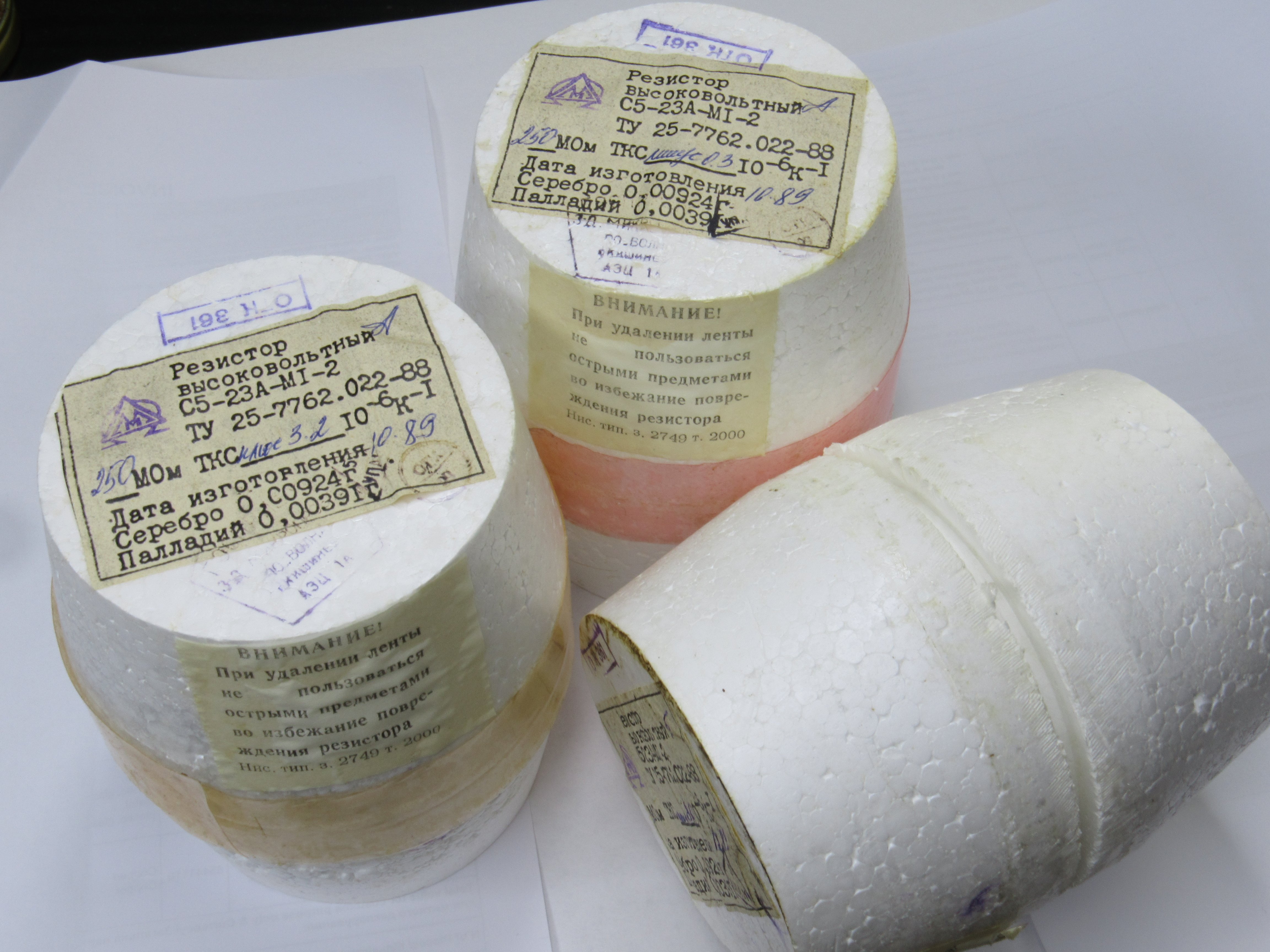
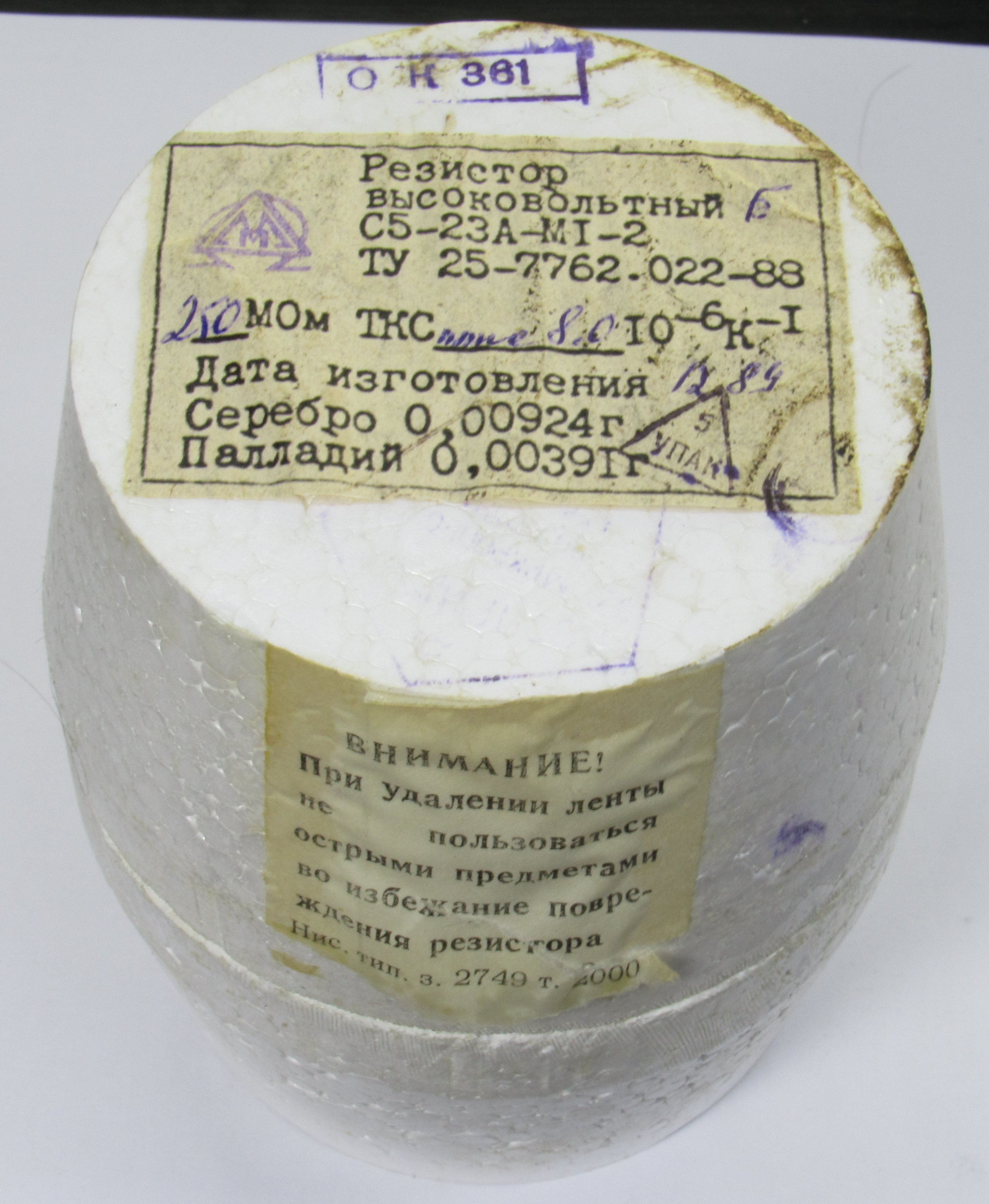
Each resistor is individually packaged in a cup made out of polystyrene foam. On the top label the measured TCR is written. For this one it is “plus 8 10-6/°C”.
Opening the packaging we can see the resistor, a datasheet and a bag of desiccant stuffed inside of the resistor.

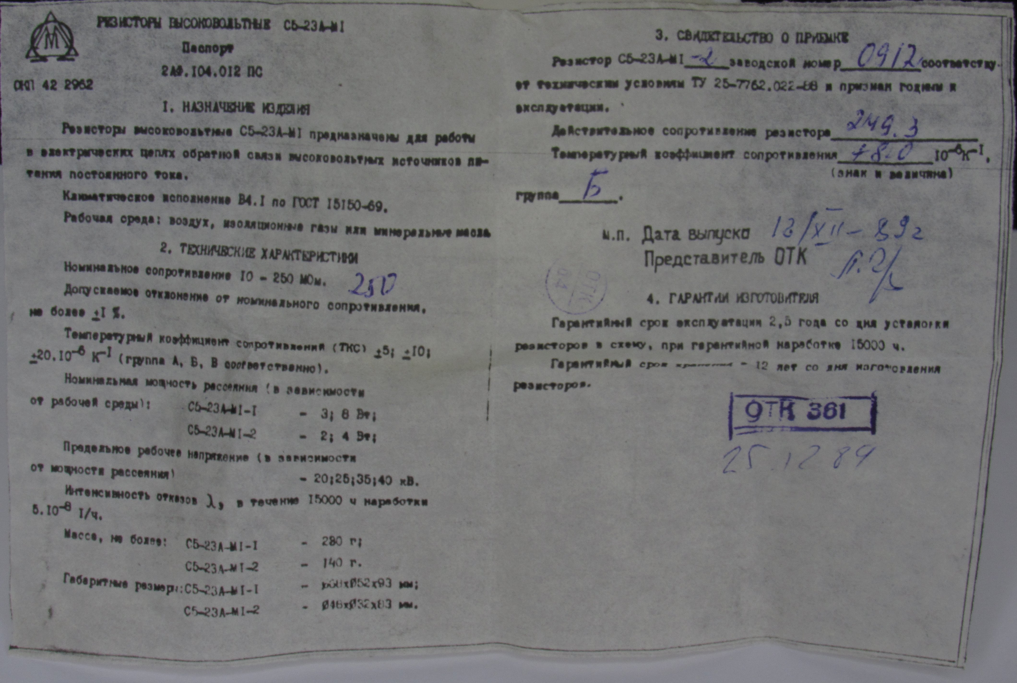
Reading the included datasheet we can see that these resistors were made with values from 10M to 250M, there are three TC groups A, Б, B – ±5, ±10 and ±20 µΩ/Ω/°C respectively. There are two versions of this resistor with different power dissipation capabilities. This one is the smaller type, S5-23-M1-2. It can dissipate 2 W in air and 4W in oil. The maximum voltage is 20 kV in air and 35 kV in oil. On the second page the measured resistance and TCR values are provided. This resistor was made in 1989.
Checking the construction of the resistor, its base is a glass tube that has end caps soldered to it and wire wound on it. Then the resistor is potted with a silicone potting compound. It is quite soft and can be easily cut by a knife.
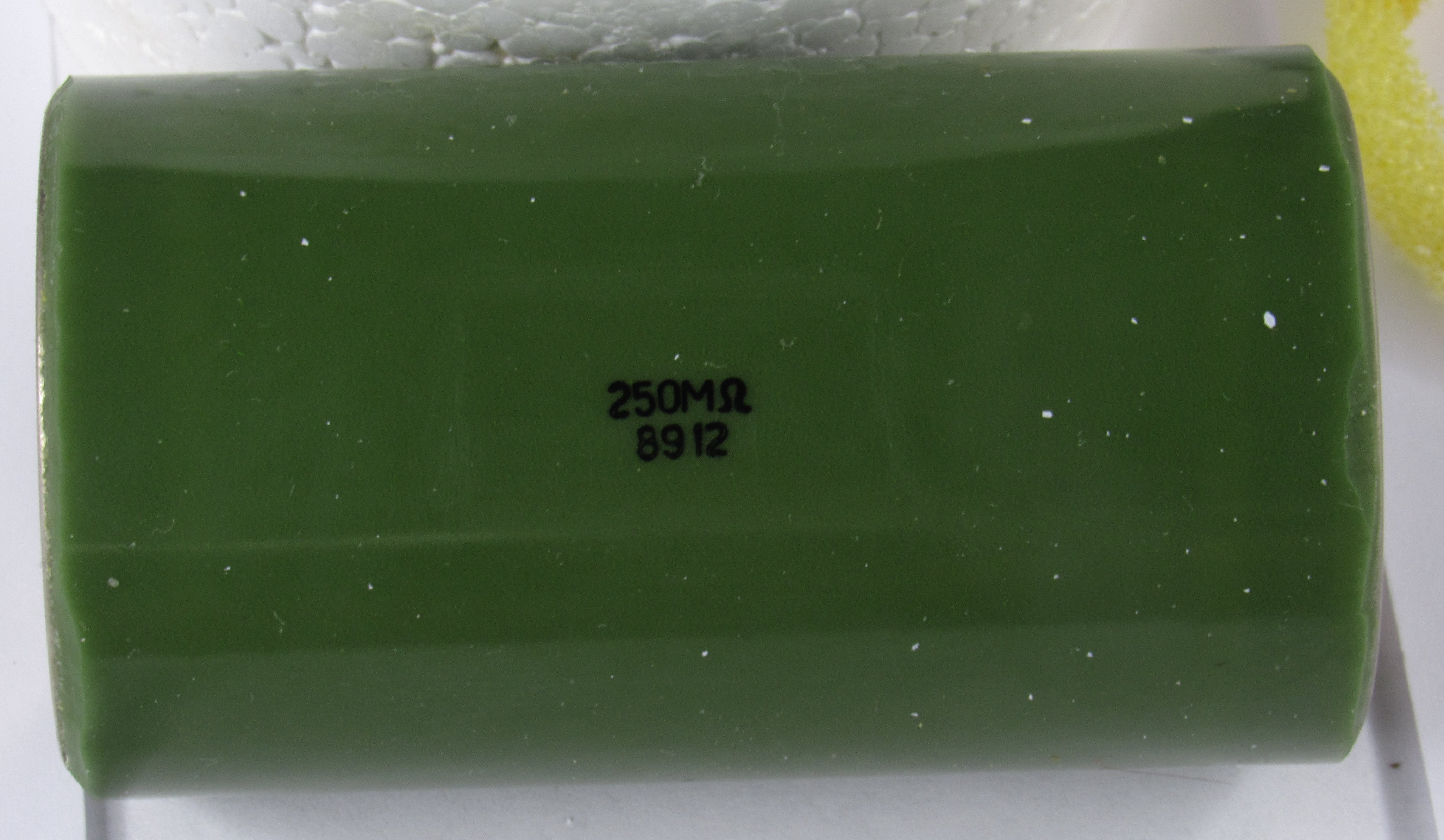
The glass tube is transparent and the potting compound is translucent. Because of this we can see the resistors insides without disassembling it. The wire is wound uniformly in a single layer.
Here is a photo of the bigger S5-23A-M1-1 version with the smaller one for reference.
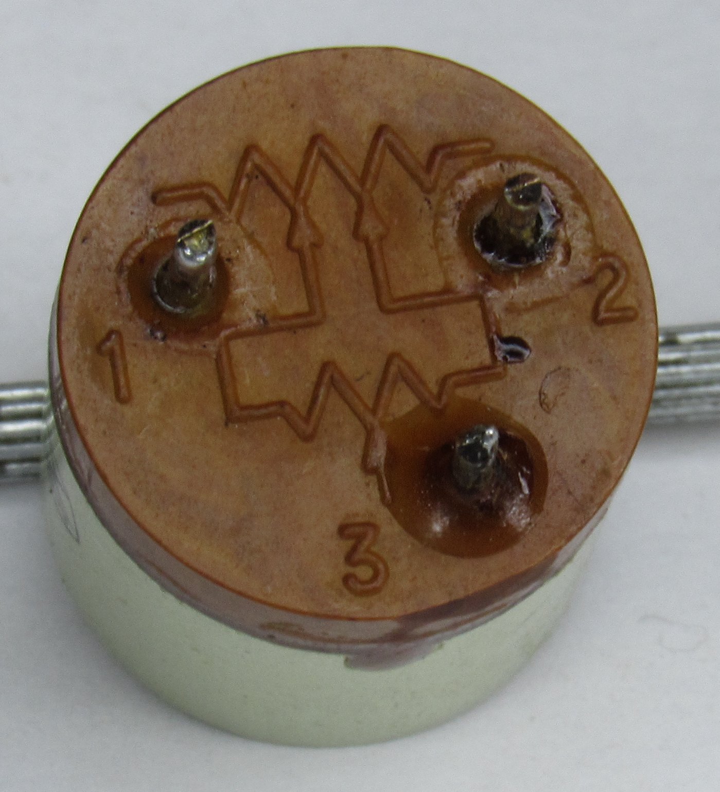
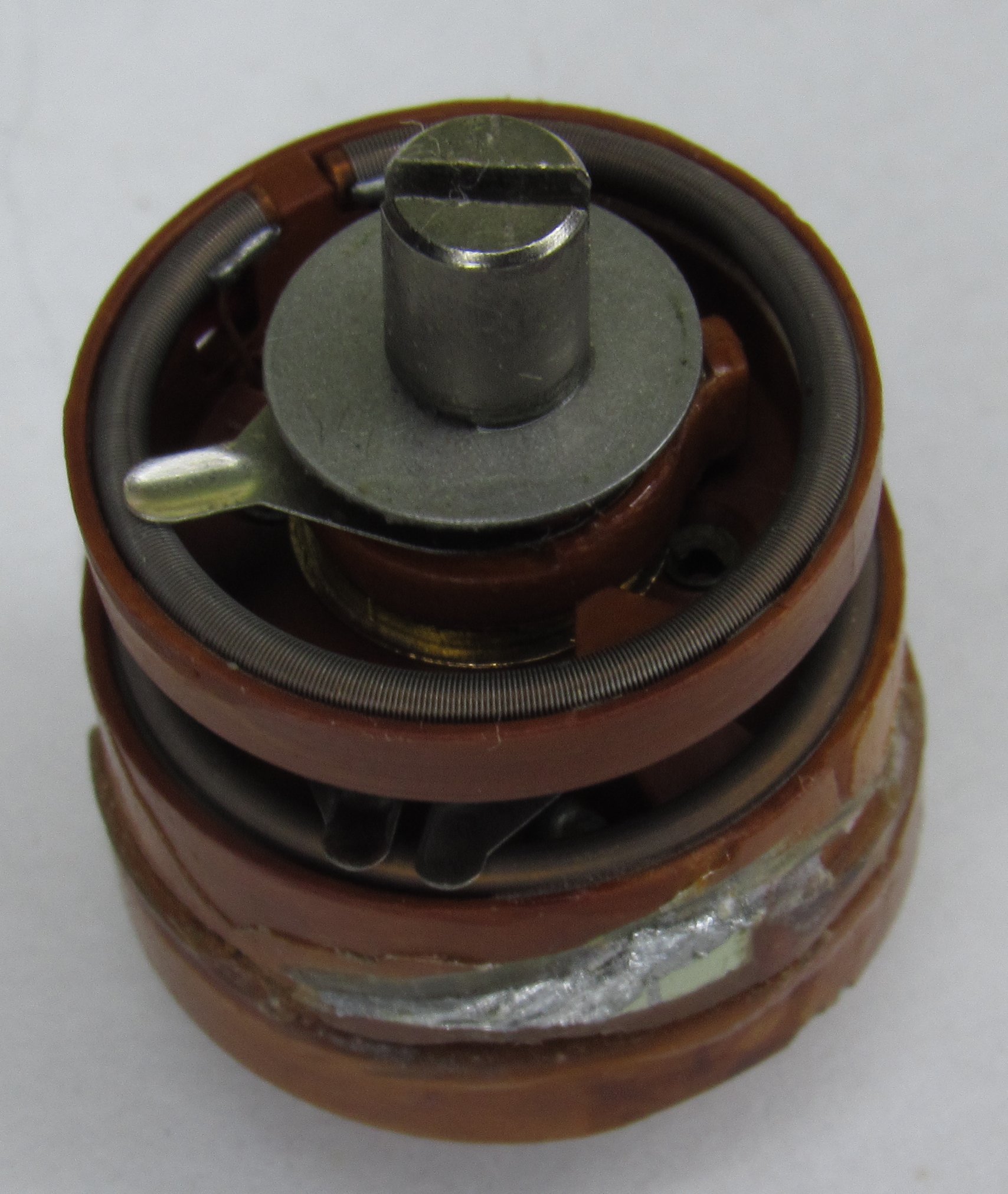
SP5-35 fine/coarse potentiometer
This potentiometer has a fine and a coarse resistance element. When the end of travel is reached with the fine element wiper, the coarse element wiper can be rotated. This can be seen by the diagram on its underside and its construction.
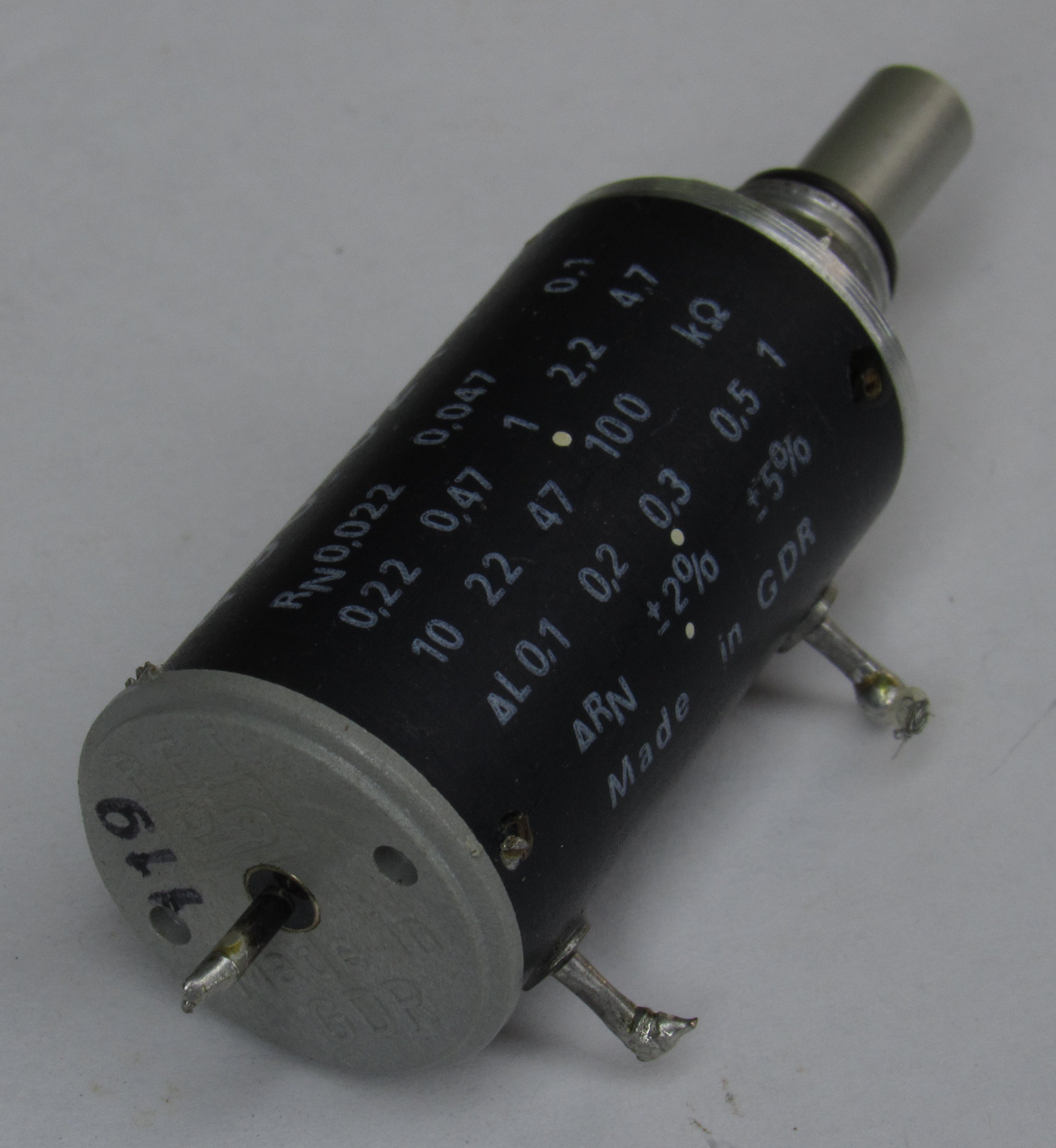
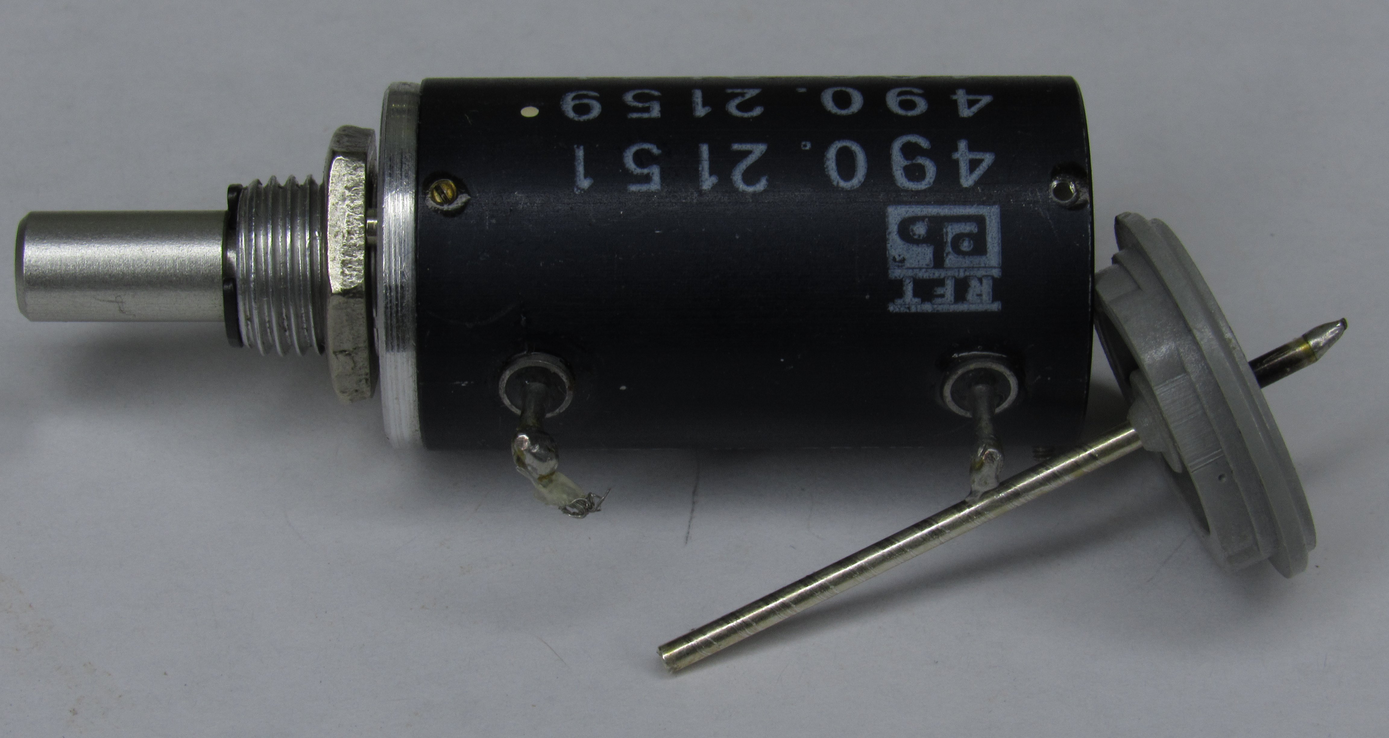
GDR 10 turn potentiometer
This 10 turn potentiometer, marked 490.2159 is a precision 10 turn potentiometer with specified linearity. It has a rather weird construction, the pins are made out of hermetic feedthroughs that are glued to the case.
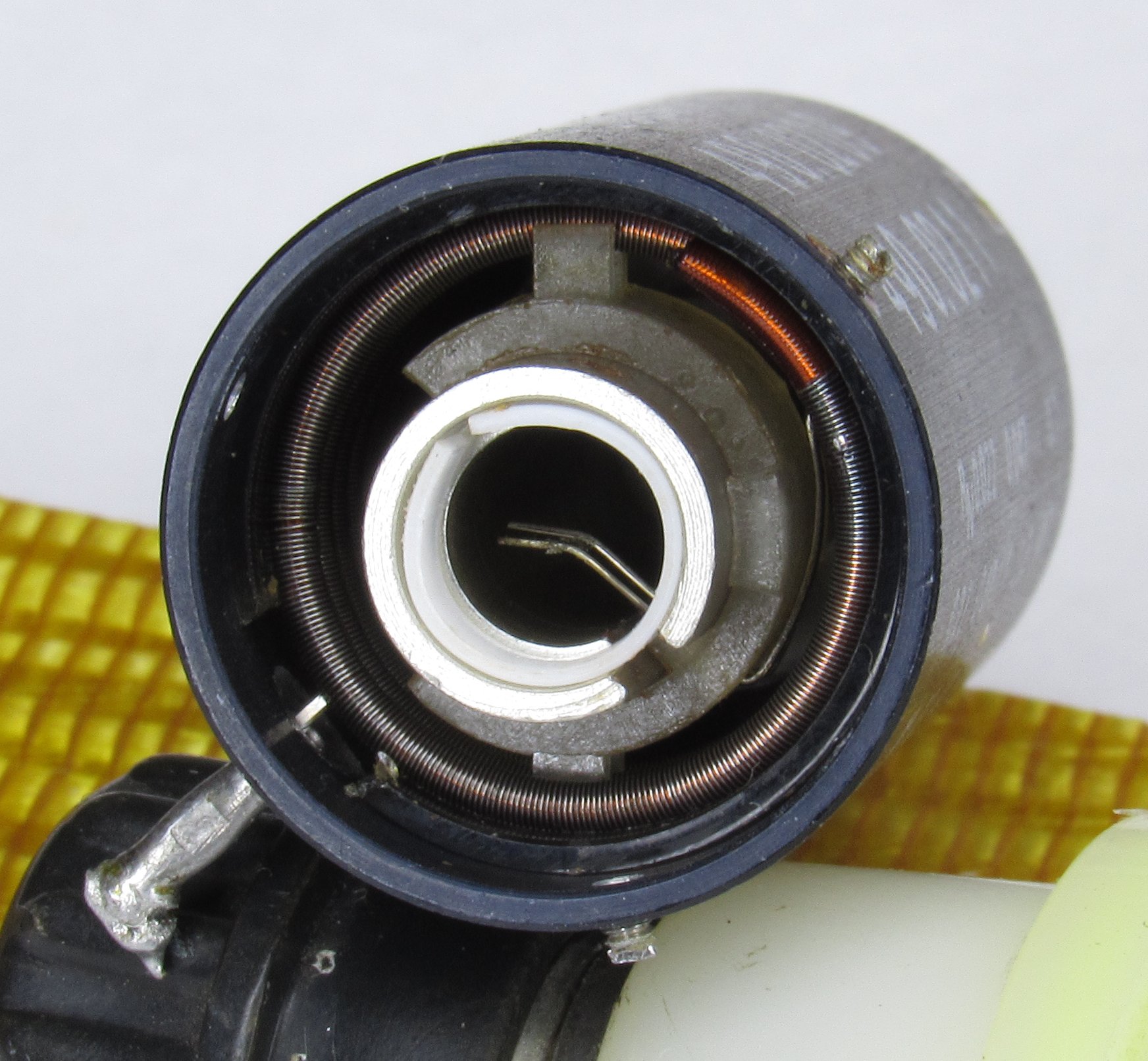
If we take out the back plate we can see that the wiper contact is a hermetic feedthrough that is very long, being made out of kovar it has a high thermal EMF to copper.
Peeking inside we can see the construction of the wiper. It is very simple – the wiper is made as a piece of bent wire that contacts the resistive element and the wiper output pin. The wiper is inserted into a piece of plastic that isolates it from the metal shaft. The plastic piece also transfers rotation from the metal shaft to the wiper and guides it along the resistive element. The resistive element is wound on a copper enameled wire.
GDR metal foil power resistor
Another East German resistor, this time – power resistor.

Using a soldering iron to heat it from the bottom and pulling on the leads is all that it took to disassemble it.
The construction is extremely simple. The resistance element is a foil of a solderable resistive metal – likely manganin or konstantan with soldered on copper leads. The resistance element is glued to a polyimide film that insulates it from the aluminum substrate. Then the whole construction is potted in epoxy.
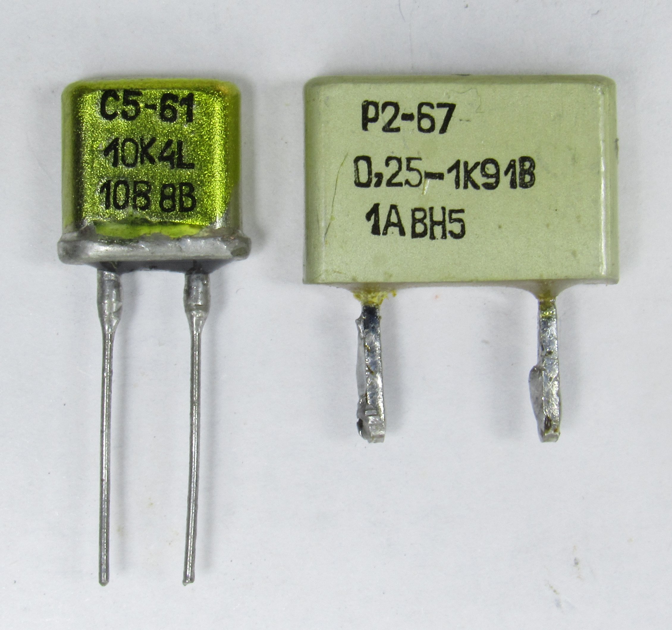
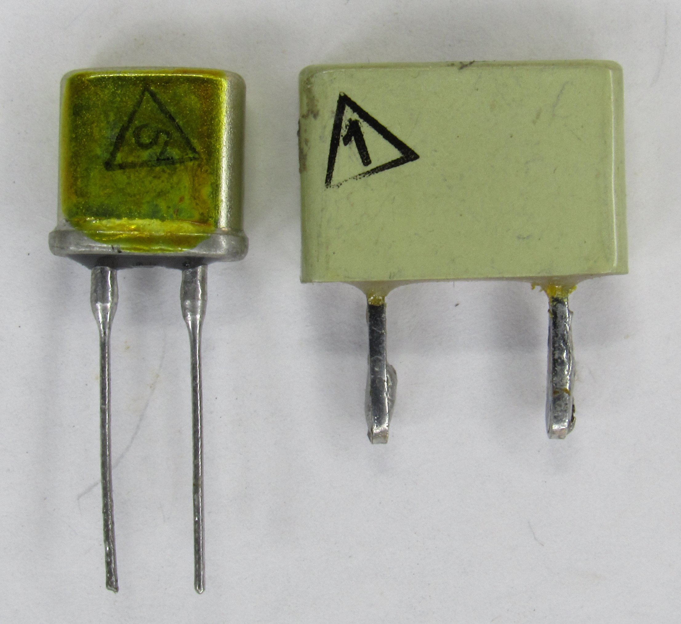
S5-61 and R2-67 metal foil resistors
These are precision metal foil resistors, the S5-61 is in a hermetic glass-metal sealed case, and the R2-67 is just encapsulated in plastic and aluminum shell. The best TC spec for these resistors is 5 µΩ/Ω/°C.
Just a dremel with a cutting disc is enough to pop them open.
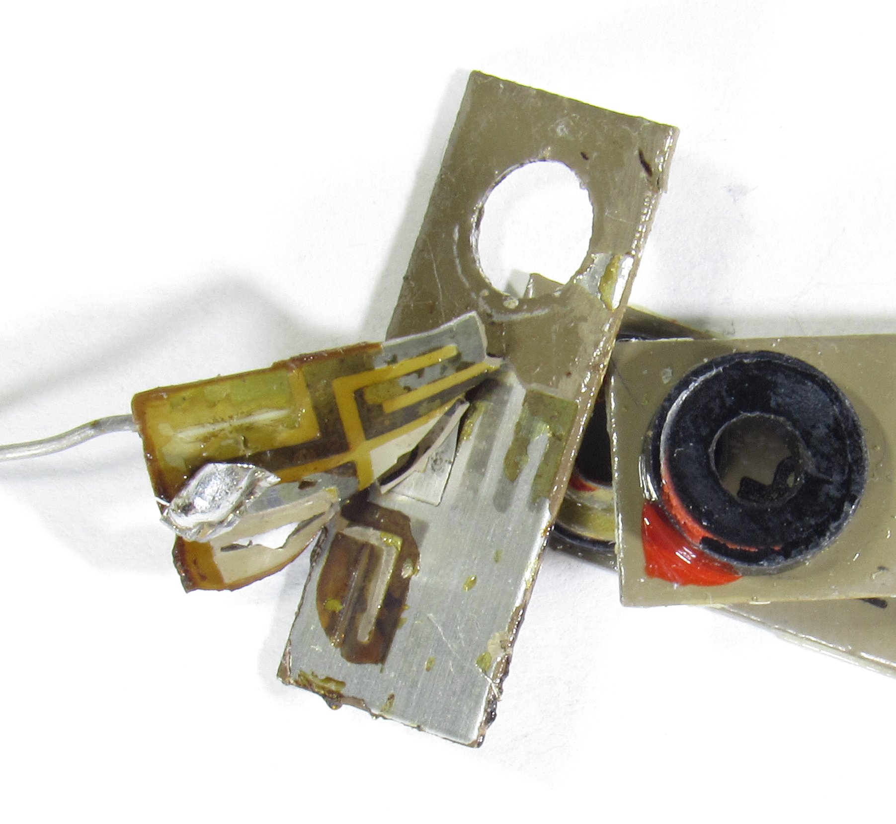
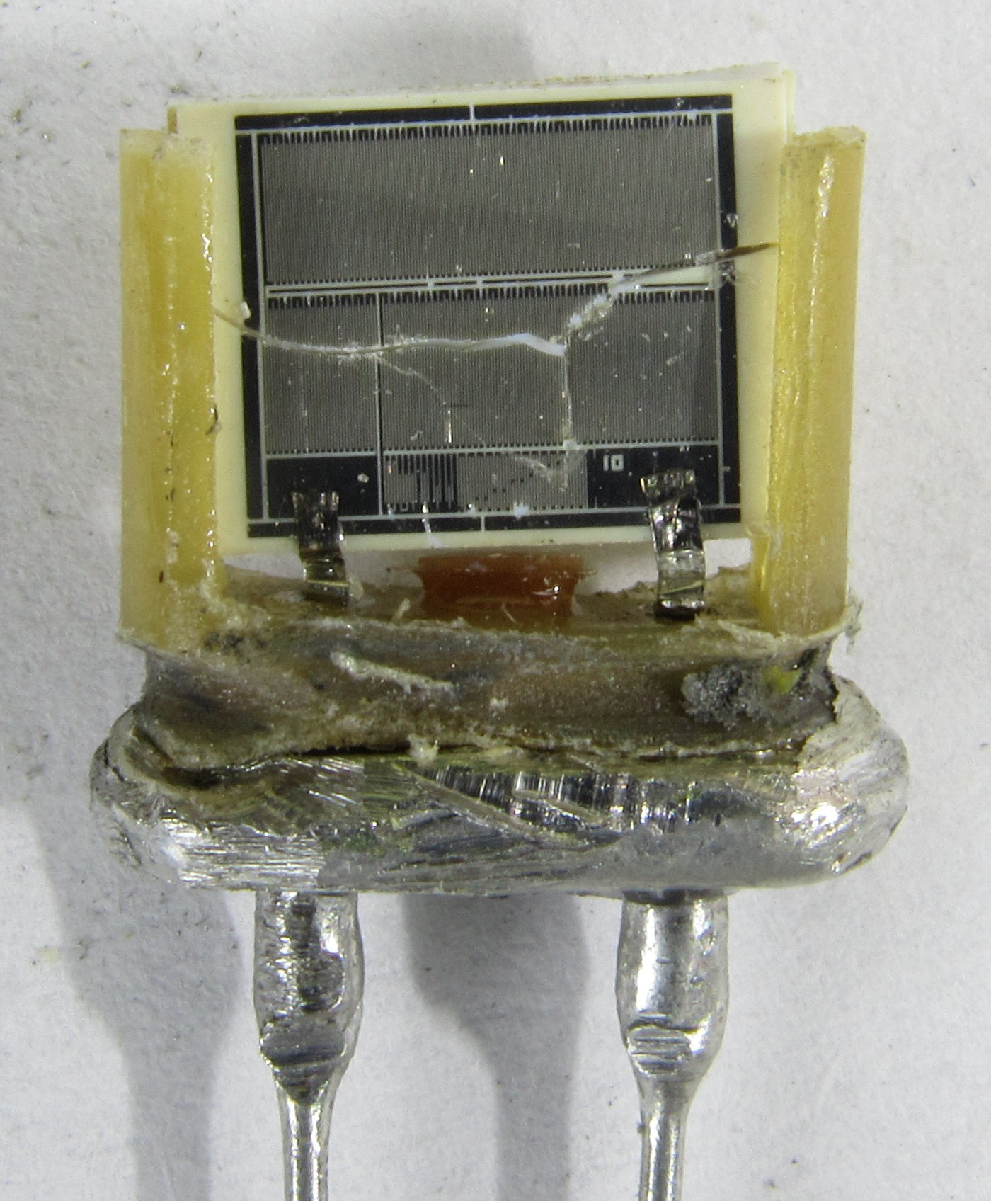
The S5-61 internal resistance element chip got cracked during teardown. It has another trim element behind the main element that isn’t used. The resistive element is welded to brass leads with thin metal strips. The R2-67 is made as a series connection of two chips, each measuring about 960 Ohm for 1910 Ohm in series.

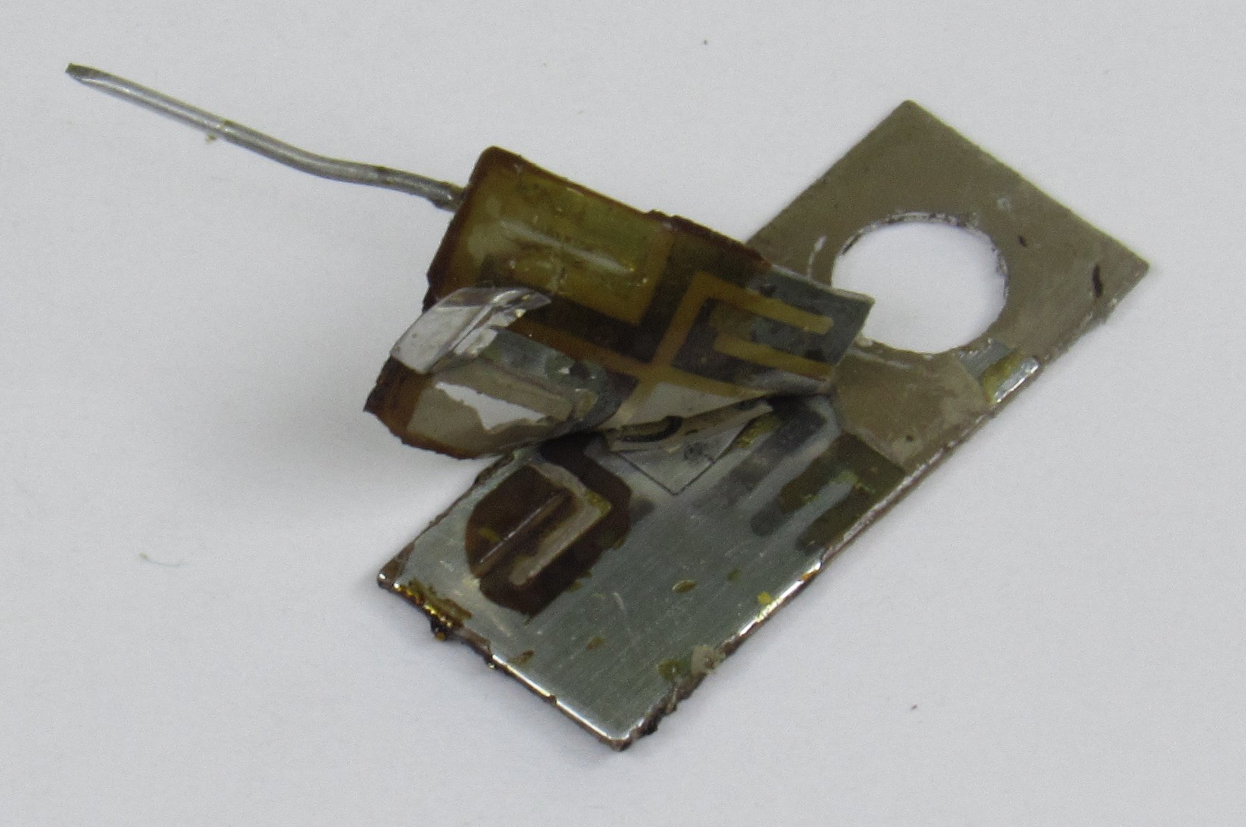
Taking a closer look at the S5-61 resistive element, since it is a high value (10k4) the traces are very fine, and can barely be seen. On the top, middle and bottom laser trimming marks can be seen.
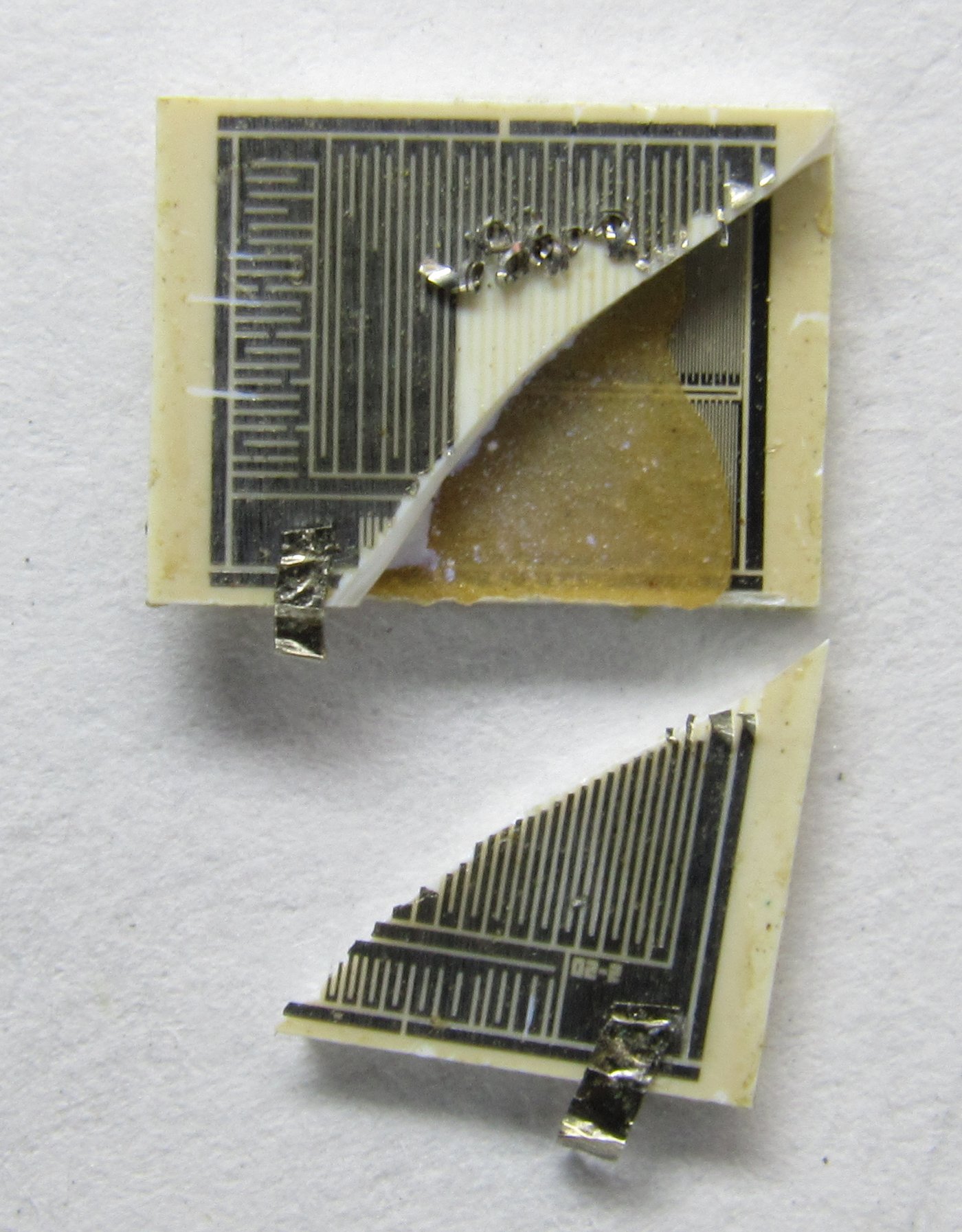
Checking a lower value (340R) resistors element, the pattern of resistive traces is a lot easier to see. This resistor also had an unbonded higher value trim chip on the bottom. The S5-61 chip size is 8×6 mm, a single chip is 0.5-0.6 mm thick.
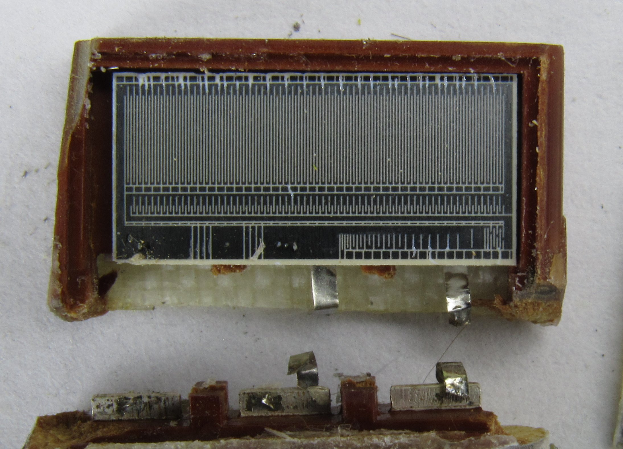
The R2-67 resistor (the 0.25 W variant) has a wide chip (13×6 mm), there are a lot of laser trimming marks.
Discussion is very welcome at our IRC chat server
Projects like this are born from passion and a desire to share how things work. Education is the foundation of a healthy society - especially important in today's volatile world. xDevs began as a personal project notepad in Kherson, Ukraine back in 2008 and has grown with support of passionate readers just like you. There are no (and never will be) any ads, sponsors or shareholders behind xDevs.com, just a commitment to inspire and help learning. If you are in a position to help others like us, please consider supporting xDevs.com’s home-country Ukraine in its defense of freedom to speak, freedom to live in peace and freedom to choose their way. You can use official site to support Ukraine – United24 or Help99. Every cent counts.
Modified: June 7, 2025, 12:48 p.m.