And since electronics engineer usually have to do a lot of soldering and want to keep process enjoyable, had pulled a trigger to buy good soldering gear. When I was little student, one engineer was educating me and at that time I heard and even tried to use ERSA DIG2000 soldering. Years passed, but I still remembered that good experience.
So from today I got own piece to play with. I enjoy working with decent equipment, even counting that it’s noticeably more expensive. Motto buy less but better is worth a try to follow.
It come with complete set, 150W i-Tool, base controller/station, power cord and iron holder (forgot it at lab, so not shown on photos).
As usual, DSLR gear come handy taking hi-res photos, so all clickable and enjoyable.
![]()
Front panel have big inverse graphical LCD, tool proprietary DIN-style connector, real power switch and encoder with combined button.
![]()
Base unit rather bulky and heavy, have linear xfrmr inside, but looks nice.
![]()
Rear have only IEC input plug with earth pin, as ICON features ESD protection (have ESD iron and grounded tip, measured resistance to mains earth pin ~1 ohm)
![]()
Bottom have nothing interesting, disassembly just simple 4 screws, and removing plastic knob from encoder.
![]()
Like Dave says, we are in like Flynn :)
![]()
Transformer occupy most of space, rated 80W (3.3A 24V), so that’s where goes that confusion of labeled 80W on Icon, but 150W soldering iron.
![]()
All interface and control gear fitted on nicely done PCB, sitting on plastic holders. Nice connectors everywhere, heatsinks on output switch and local POL supply.
![]()
Main brains are in ATMEL ATmega128-16AU 8-bit AVR, with some opamps and passives around. Current sensing is based on 50 mOhm resistor located nearby. There is also space
for some unknown TQFP or QFN package nearby.
LCD is fixed to board really good, white LED backlight mounted with 4 screws, and panel itself connected via flat ribbon cable. It’s COG type screen, with controller right on glass.
![]()
Bourns encoder with metal shaft.
![]()
Seem like there is routing for second channel as well, as there is ICON2 model which allows using two tools.
![]()
And yes, PCB is same, marking on etch have label ICON2.
![]()
Any owners of ICON2 here, so we can reverse engineer it a little and upgrade ICON1 to ICON2 ? :D
![]()
LCD is graphical, with okay contrast (can be adjusted), but that’s not most important thing on soldering stations. Lots of them just have blinking LED and it’s okay too.
Font on LCD is somewhat ugly. They could do better job on GUI looking, but controls and navigation is easy and intuitive. No need to dig into manual to start using station at all!
Thumbs up for usability.
All the magic and efforts go to soldering iron, that’s where difference between 20$ iron and 600$ one lies..
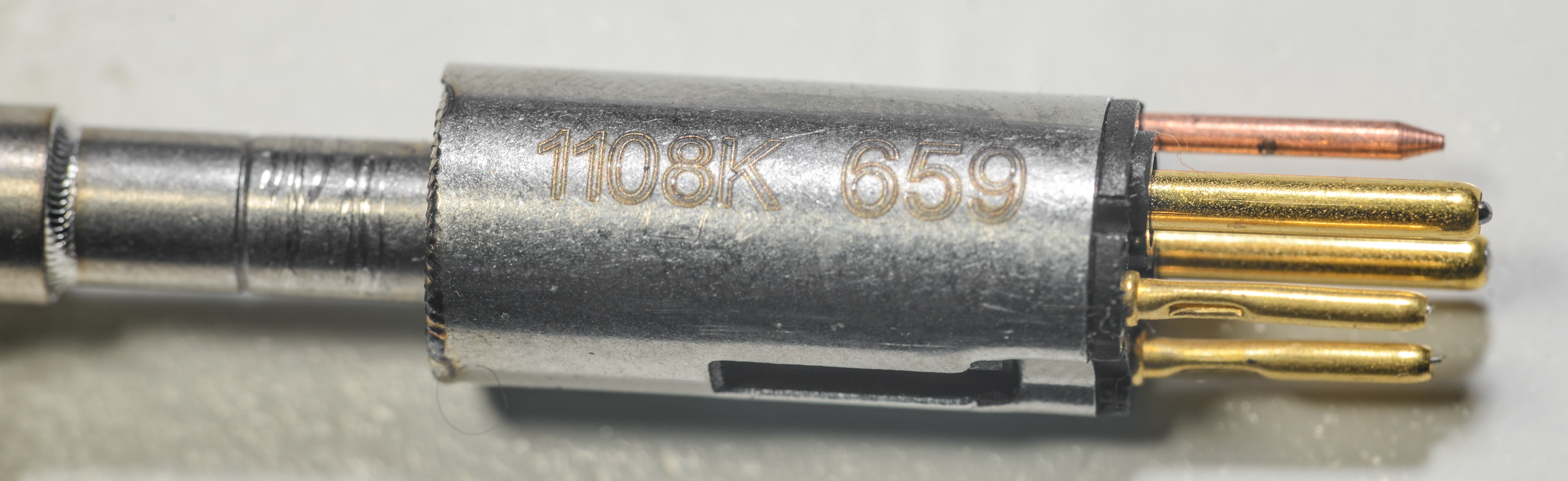
Also soldering iron handle have PCB inside, with another ATMEL ATmega microcontroller and Analog Devices ADXL323 iMEMS 2-axis accelerometer. This is used for automatic warm-up when iron entered sleep mode, and user picks iron from the stand. Use of accelerometer feedback allows this function to work with any stand.
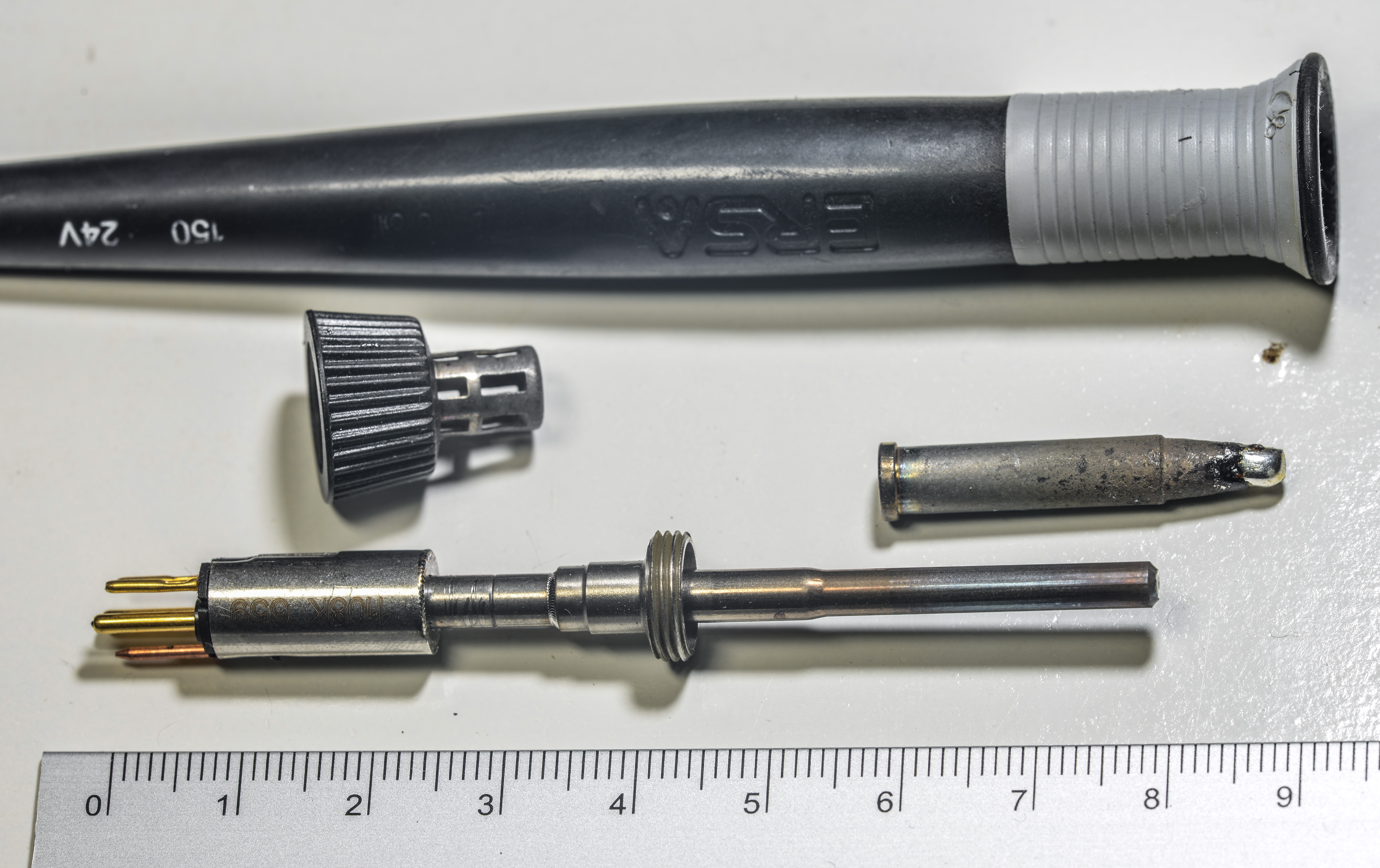
Seem pretty usual, but take a close look on ruler. It’s in centimeters, not inches.
This size is pretty common for 15-20W irons, but here on ERSA we have 150W max and 80W nominal!
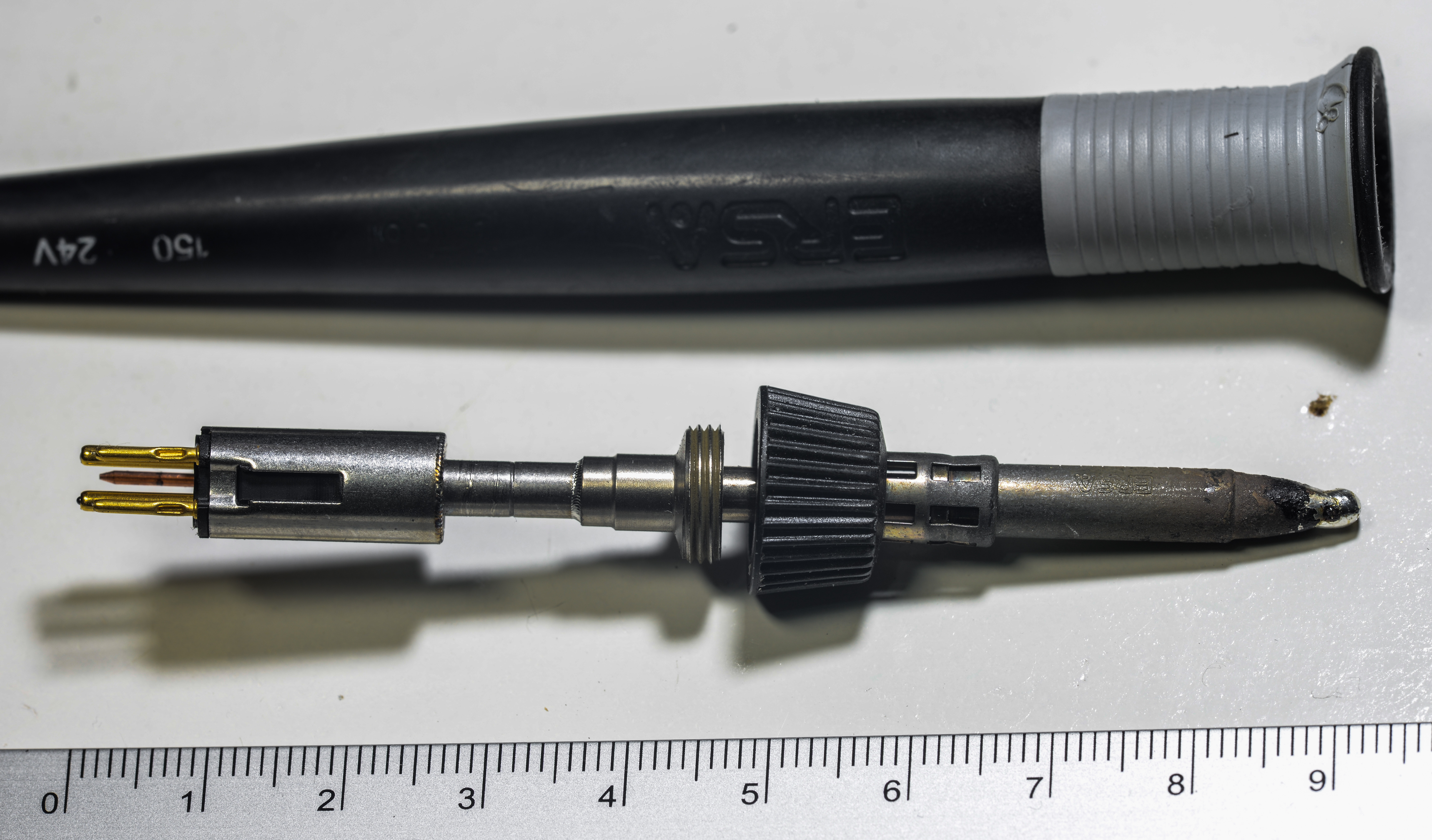
Heater element is easy to replace, connected with connector. There should be some circuitry inside holder as well, there is motion sensor somewhere (detect movement to bring up operation from standby).
I’m not going to disassemble it any further, sorry.
Unlike some newbies think, soldering is all about thermal conductivity and capacity, not temperature set point. That’s exactly the reason why big-ass soldering tip working much better than 0.8 cone tip.
More surface – more power dumped into joint and more contact area to transfer heat. That’s why on cheap iron you need to set 400C max temperature to be able soldering big power components on
multilayer PCB with via arrays around. Lack of surface contact and heater too far makes temperature of solder iron tip actually go below 200°C, which of course cannot solder anything.
Keeping that power transfer is crucial. And that’s why placing heater element as close to tip as possible
is vital. Otherwise heater will require to be running scorching hot to get those 260C on PCB joint.
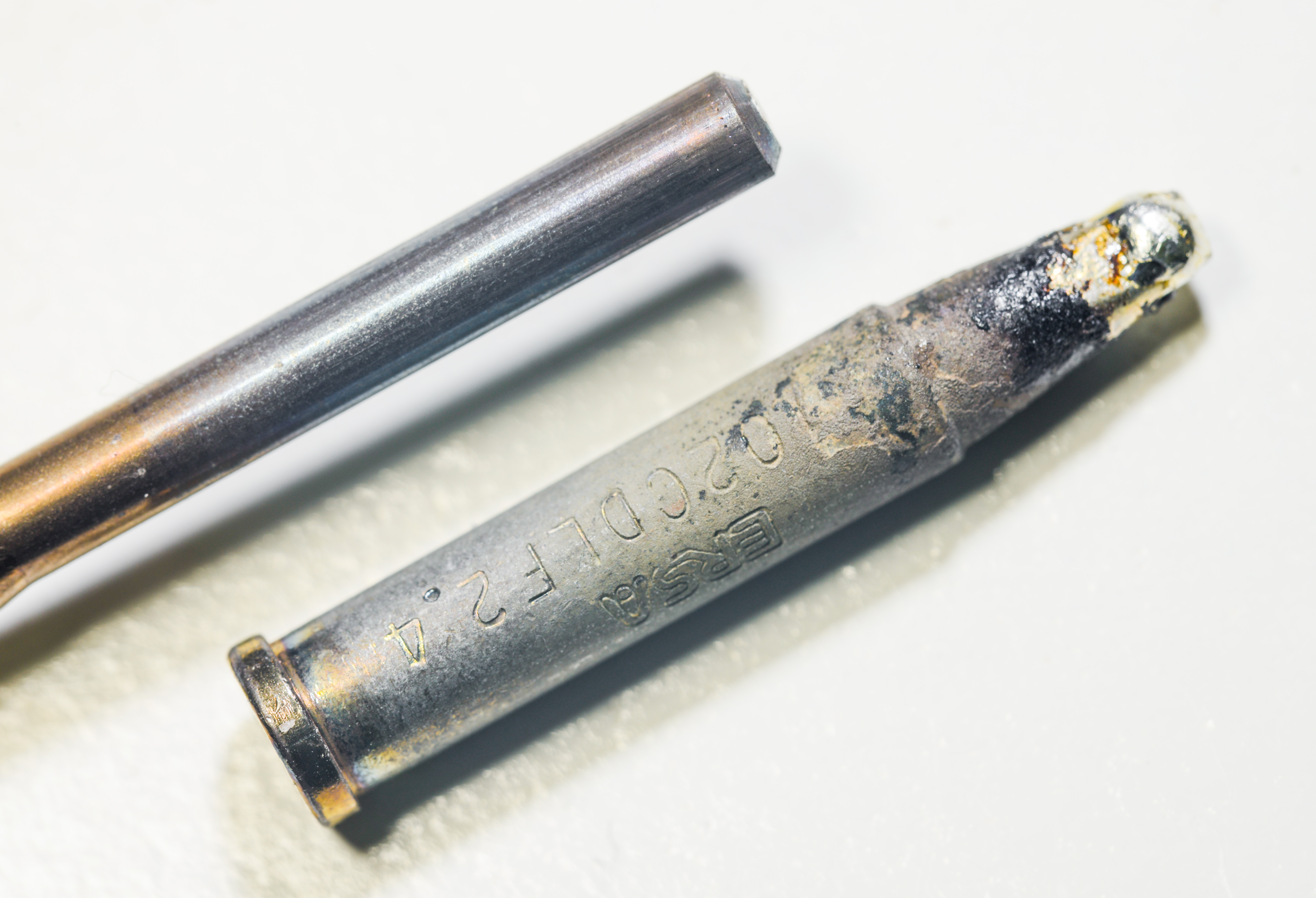
ERSA does homework pretty good, they state that temperature measurement taked from end of heater, which is encapsulated in metal shell, and is only 9mm away from tip end.
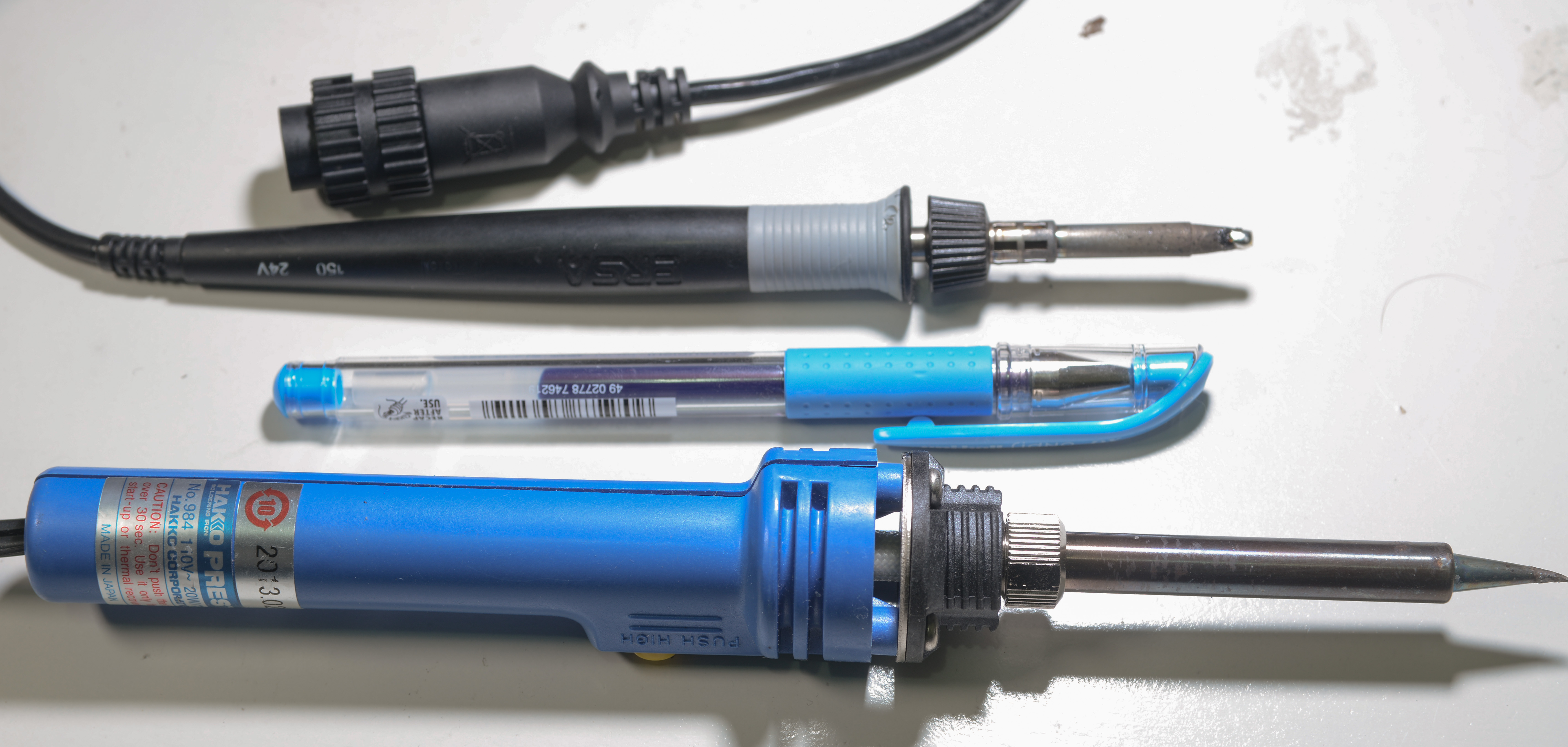
Cheapies are way too far, here’s comparsion of some generic iron:
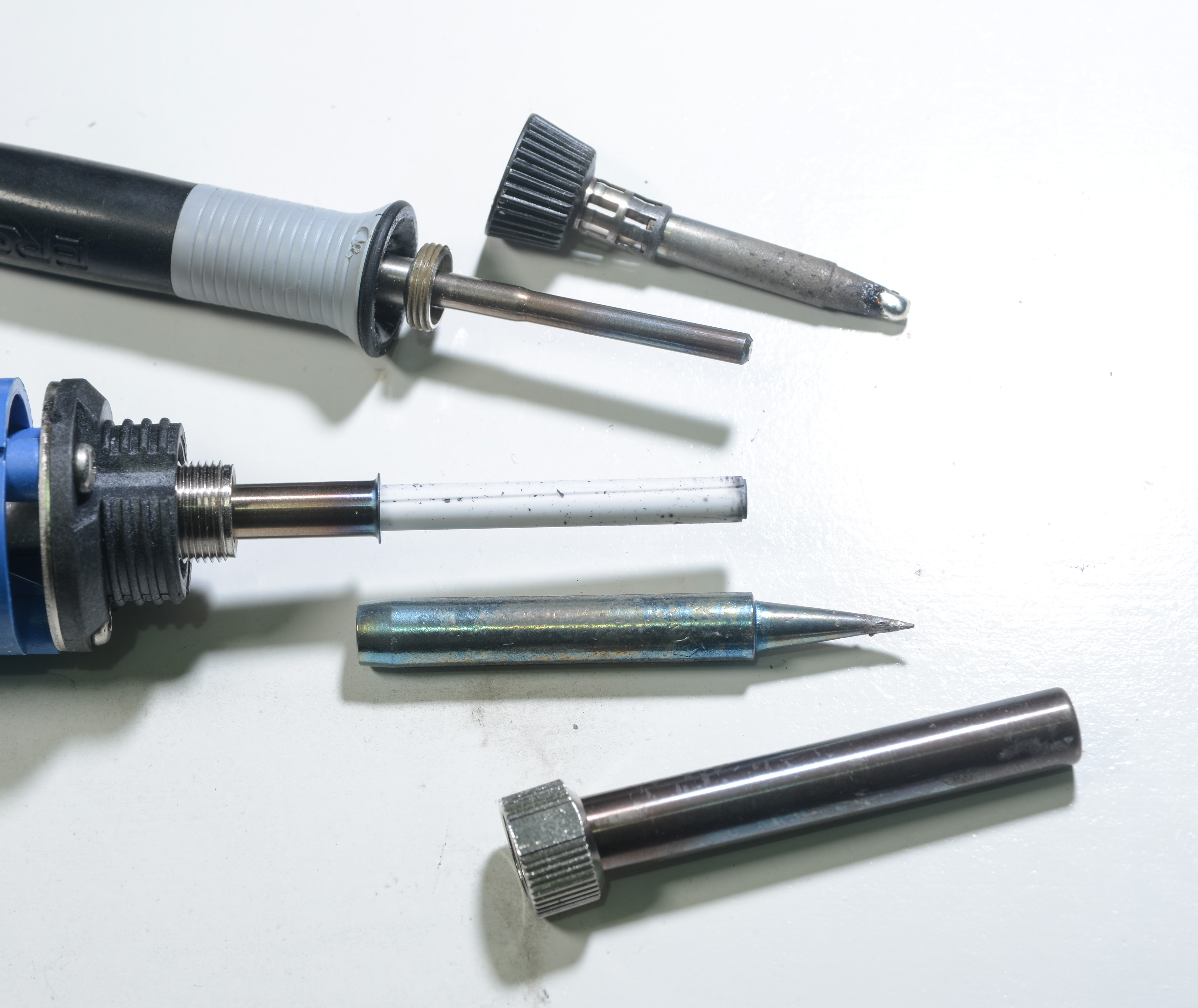
That’s 20W vs normal gel pen vs ERSA I-tool 150W.
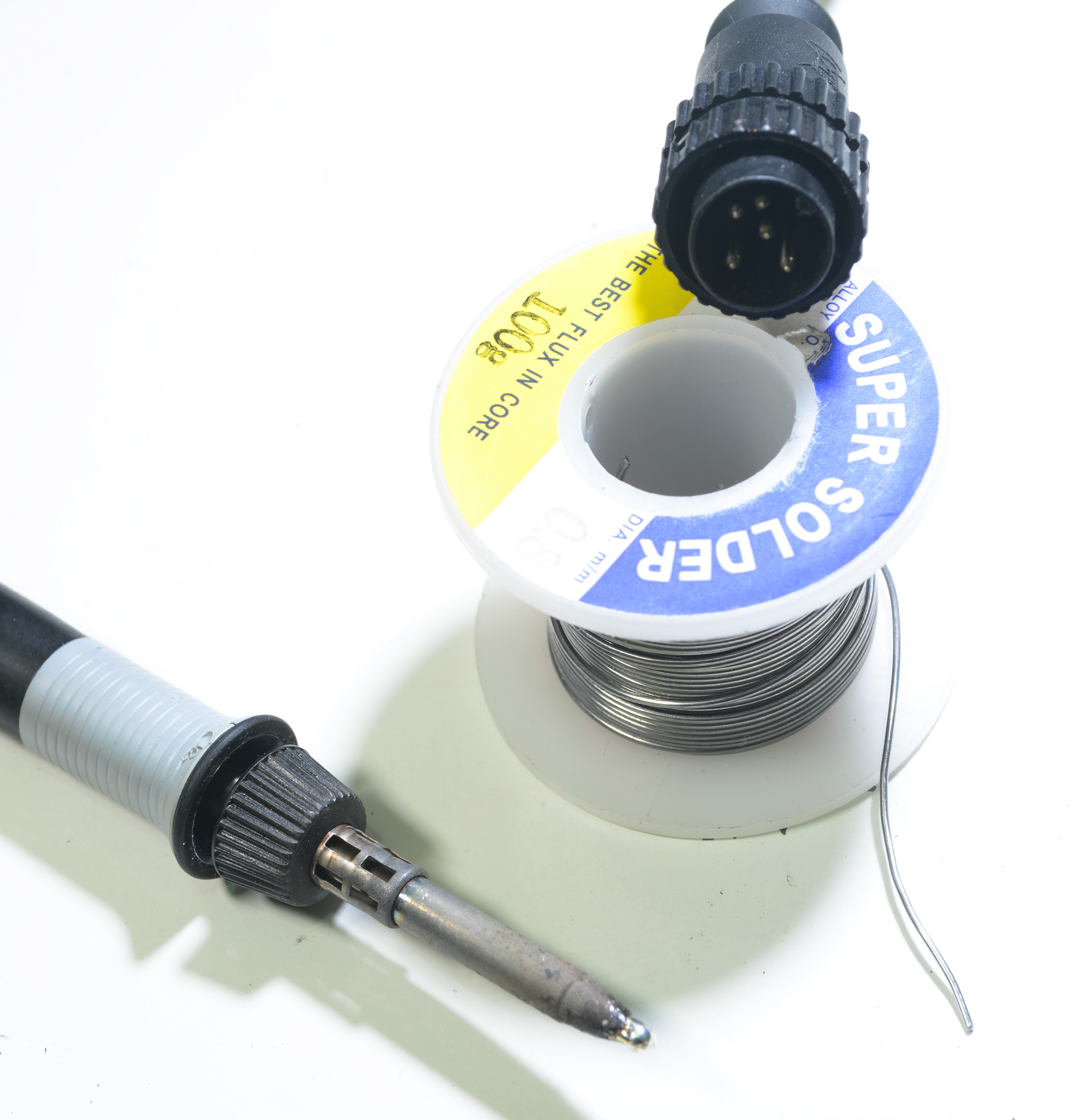
And it connects to base unit via pesky proprietary connector :)
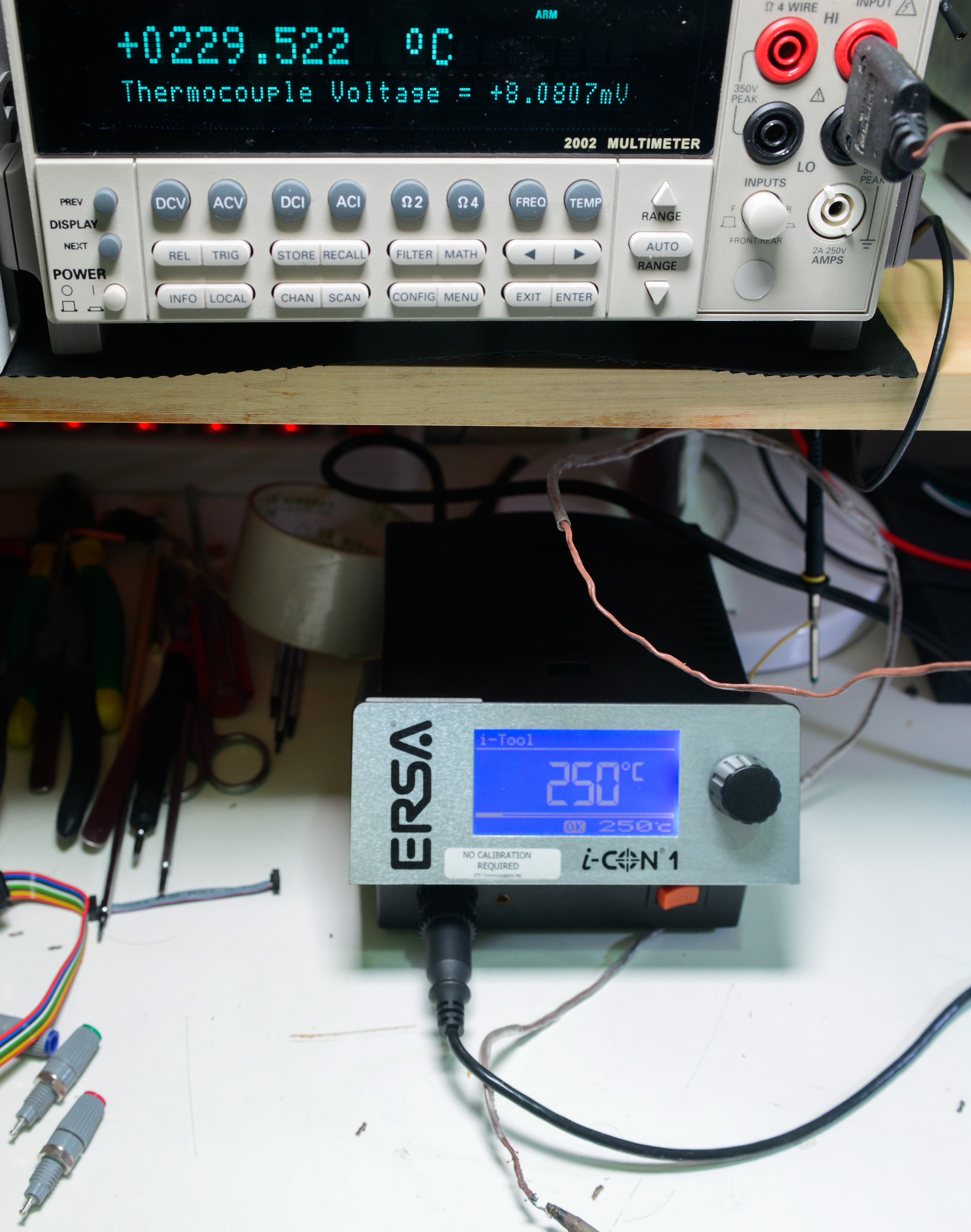
Now, power it on and check tip temperature:
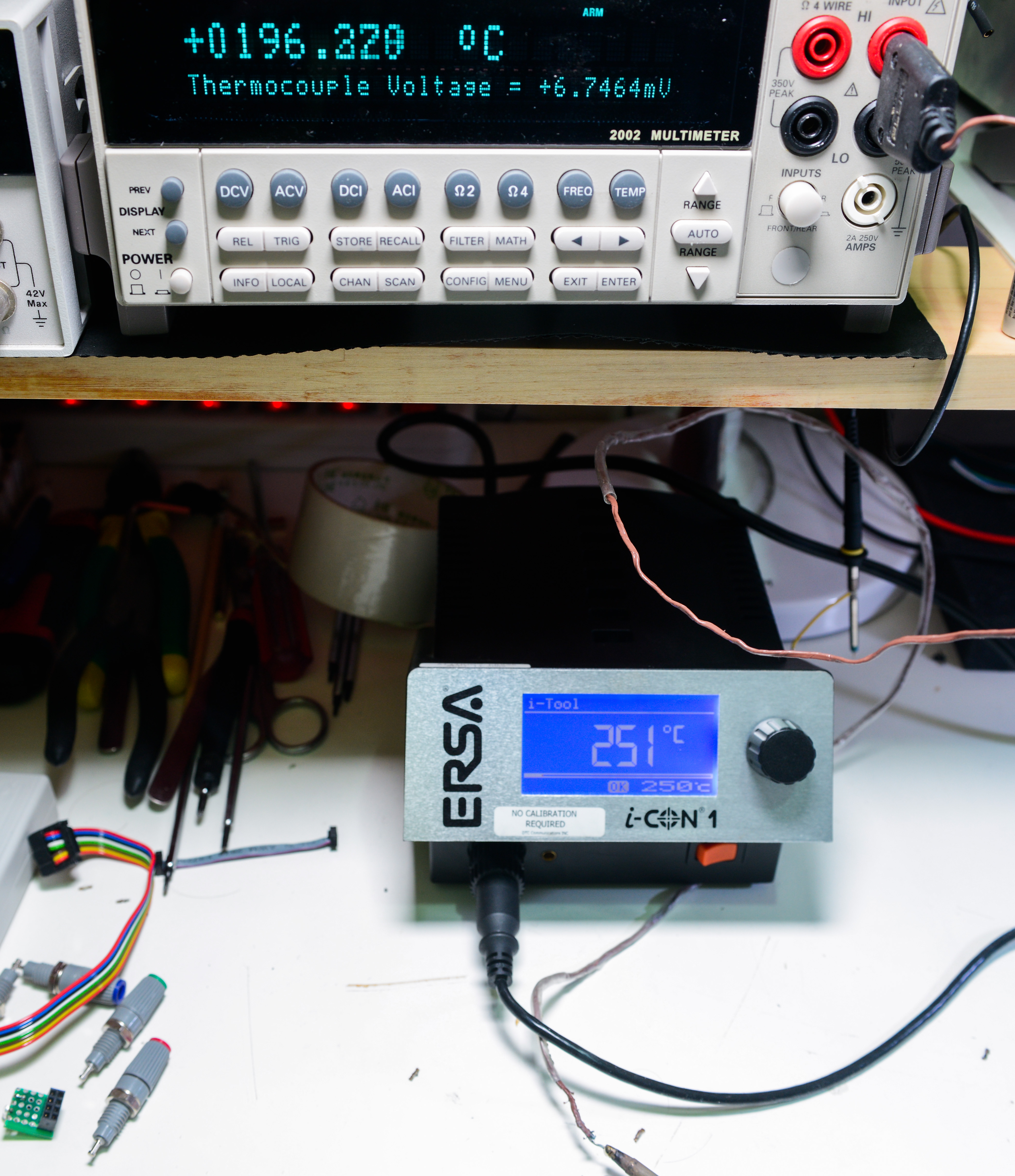
Default settings, +250°C set on station. Fluke Type-K thermal probe (one from F87V bundle) connected to Kei input. Ambient temperature +25°C
Thermocouple ball is in contact with solder tip, which have plenty of solder to improve contact area.
As we can see, it’s rather off, 54°C to be exact.
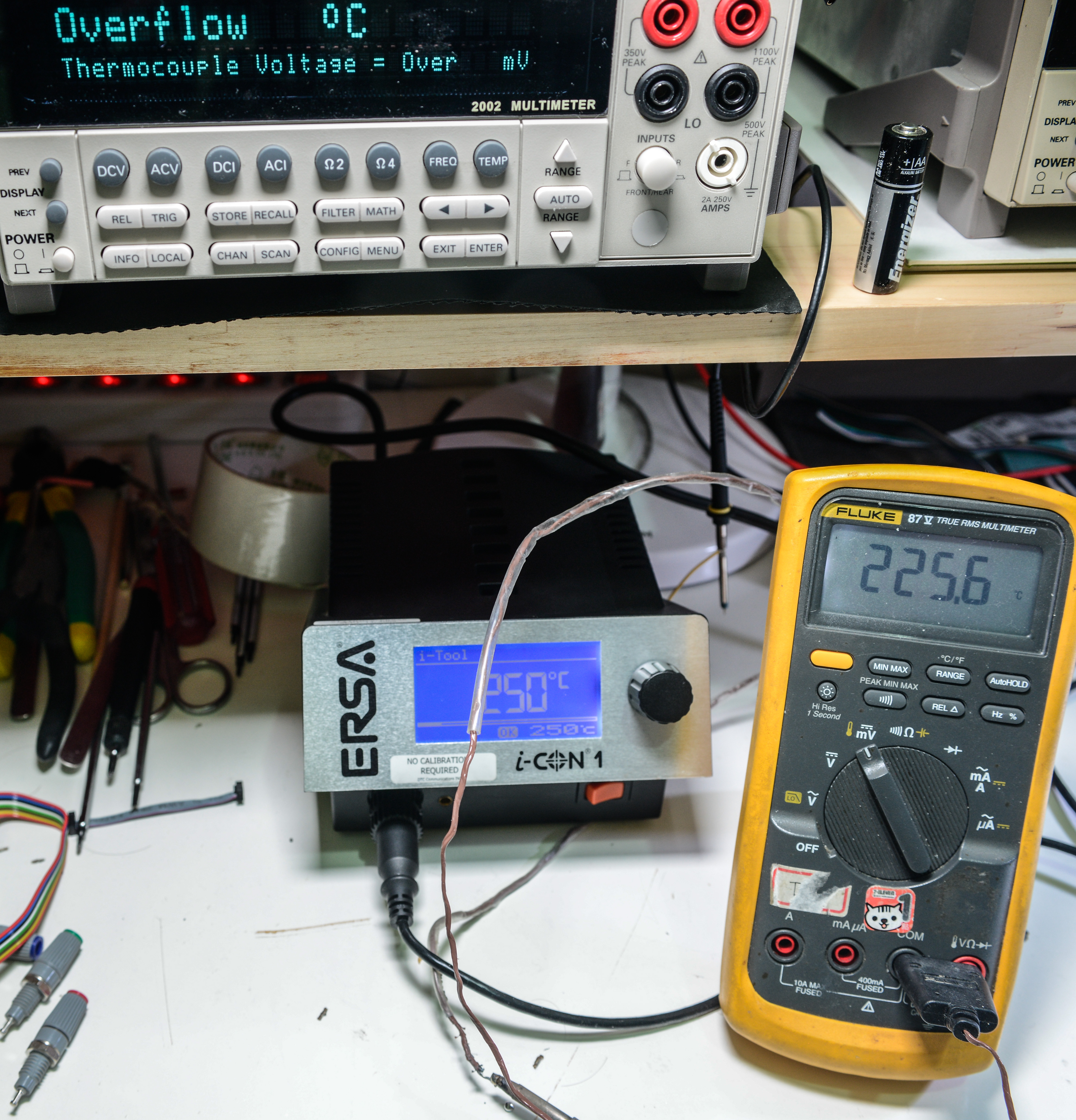
So I went to menu in I-CON, and set calibration to +50°C, that’s max it can go. (which suppose to offset temperature control for actual tip temp).
After this operation – temperature on tip raised to +230°C, still somewhat 20C off, but it’s 2.5 times better already.
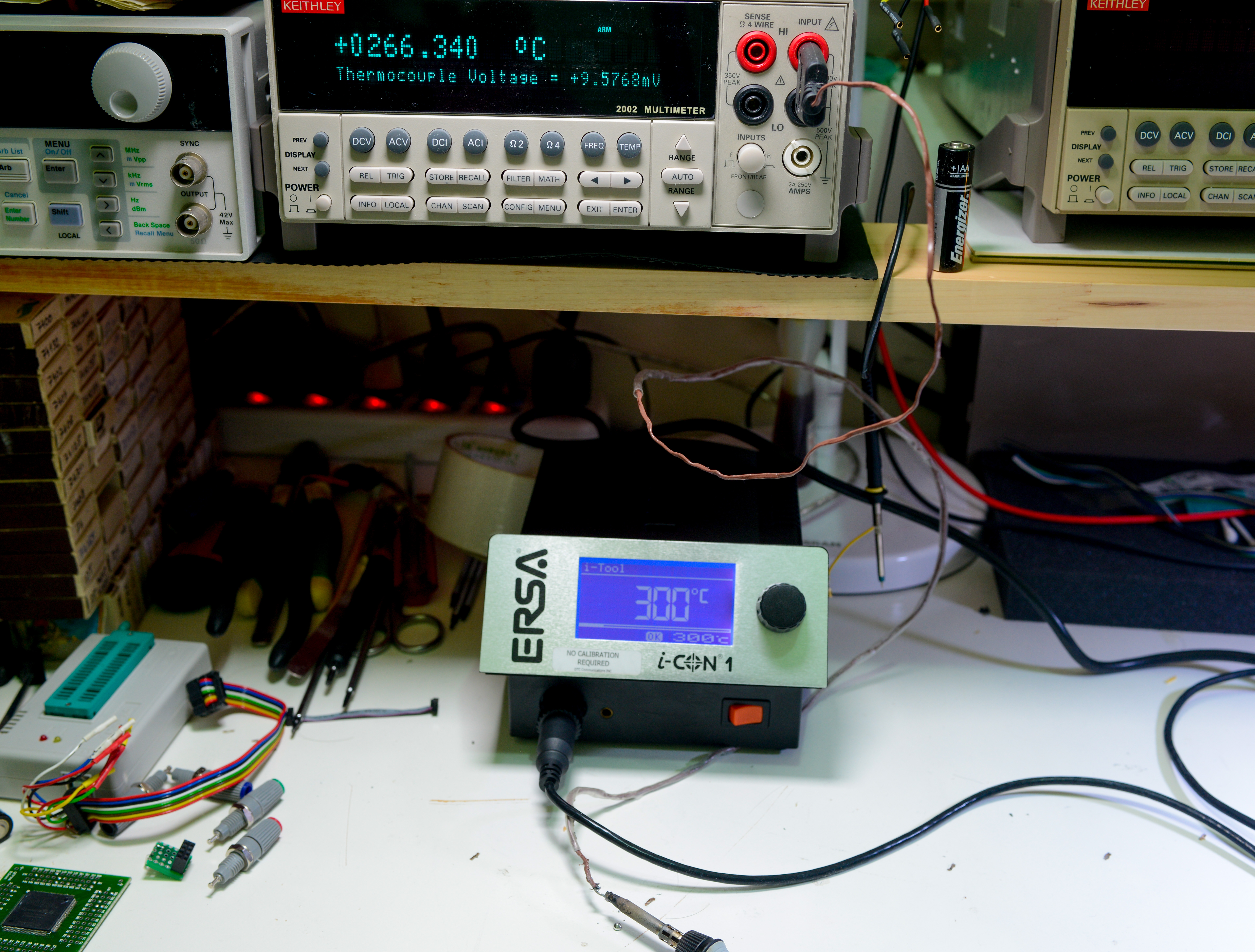
And set to 300C – get’s us 266°C. Part of this due to thermocouple act as a heatsink, causing measurement error.
Now, let’s do some real-world test. One of reasons why I bought ICON, is it’s high power ability, which should make soldering heavy-copper PCBs with multiple layers easier.
Here’s video of some checks and 12-layer motherboard component soldering (couple power inductors, via-ed power pad soldering).
Temperature was set to +300°C for soldering.
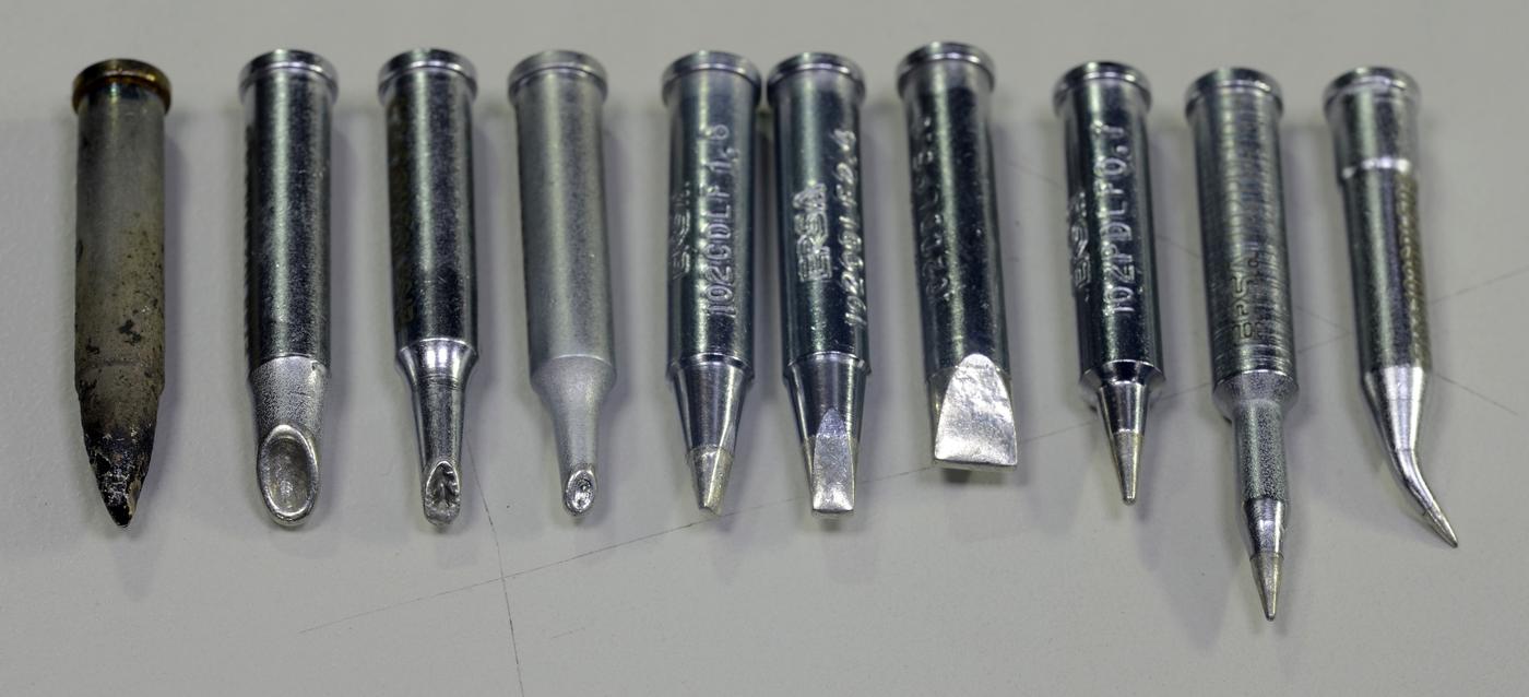
Tip setup (bought separately):
So far after use for over 15 month, ERSA still doing it’s job like day one and providing nice and robust soldering joints on any PCB we throw.
Projects like this are born from passion and a desire to share how things work. Education is the foundation of a healthy society - especially important in today's volatile world. xDevs began as a personal project notepad in Kherson, Ukraine back in 2008 and has grown with support of passionate readers just like you. There are no (and never will be) any ads, sponsors or shareholders behind xDevs.com, just a commitment to inspire and help learning. If you are in a position to help others like us, please consider supporting xDevs.com’s home-country Ukraine in its defense of freedom to speak, freedom to live in peace and freedom to choose their way. You can use official site to support Ukraine – United24 or Help99. Every cent counts.
Modified: Aug. 12, 2023, 5:44 a.m.