Contents
Intro
One of main Keithley Instruments expertise are low-level signal measurements. Since very beginning company had instruments as null-detectors, microvolt voltmeters, electrometers. As of today, current nanovoltmeter is Model 2182A, which features two channels with range down to 100mV with 7½ resolution. Predecessor of this instrument was sensitive voltmeter Model 182. It’s possible to get one of these from secondary market for about $1K USD or lower.
I had chance to get recently calibrated Model 182-M version from one of EEVBlog forums member, and we will take a look on it in details. It was also owned and calibrated by EEVBlog member acbern. Always interesting to follow used test gear life and travel across different owners.
This is specialty instrument, not a replacement of usual multimeter, such as Model 2000 or 2001 by any means. The only function is DC voltage measurement, but it does this function much better than conventional multimeter. No resistance, current or AC measurements present, so if you need any of that, there are variety of Keithley’s special meters/sources.
Other Keithley instruments dedicated to low voltage measurements are modern Model 2182/2182A and obsolete Model 1801 preamp module for Model 2001/2002 series DMMs.
Measurement capability
Here’s summary from spec for provided ranges and accuracy on Model 182.
| Range | Resolution | Accuracy 24 hours | Accuracy 1 year | Transfer stability 5min |
| 3 mVDC | 1 nV | 20 + 16 ppm with REL | 60+16 ppm with REL | 5+9 ppm with REL |
| 30 mVDC | 10 nV | 20 + 6 ppm with REL | 60+6 ppm with REL | 3+2 ppm with REL |
| 300 mVDC | 100 nV | 15 + 6 ppm with REL | 55+6 ppm with REL | 3+2 ppm with REL |
| 3 VDC | 1 µV | 10 + 4 ppm with REL | 50+6 ppm with REL | 3+2 ppm with REL |
| 30 VDC | 10 µV | 10 + 4 ppm with REL | 50+6 ppm with REL | 3+2 ppm with REL |
Maximum input voltage is 120VDC for 10 seconds, or 35VDC continuous, so do not try to measure high-voltage circuits with nanovoltmeters.
Specified noise can be as low as 15nV peak-peak with source resistance <100 Ω, according to spec. Only Model 1801 preamp for 2001/2002 DMMs, which is not available anymore, can offer lower noise and higher sensitivity.
Input impedance is at least 10 GΩ, with bias current <50 pA
Meter also provide analog output function for external datalogging device, with 0.15% accuracy and digitally adjustable gain, so Model 182 can act as an voltage amplifier with some limitations.
Meter have auto ranging function, and can read ±3029999 counts.
Manuals
It’s worth to take a look on manuals and specs.
Keithley Model 182 Quick Start manual, 182-903-01, Revision B
Keithley Model 182, 182-901-01 Revision E, June 1993 Instruction manual
Keithley Model 182, 182-901-01 Revision A, October 1990, Operations manual
Keithley Model 182 Specification, Revision B
Keithley Model 182LS Specification, Revision A – Model 182LS does not have functional analog filter
Exterior
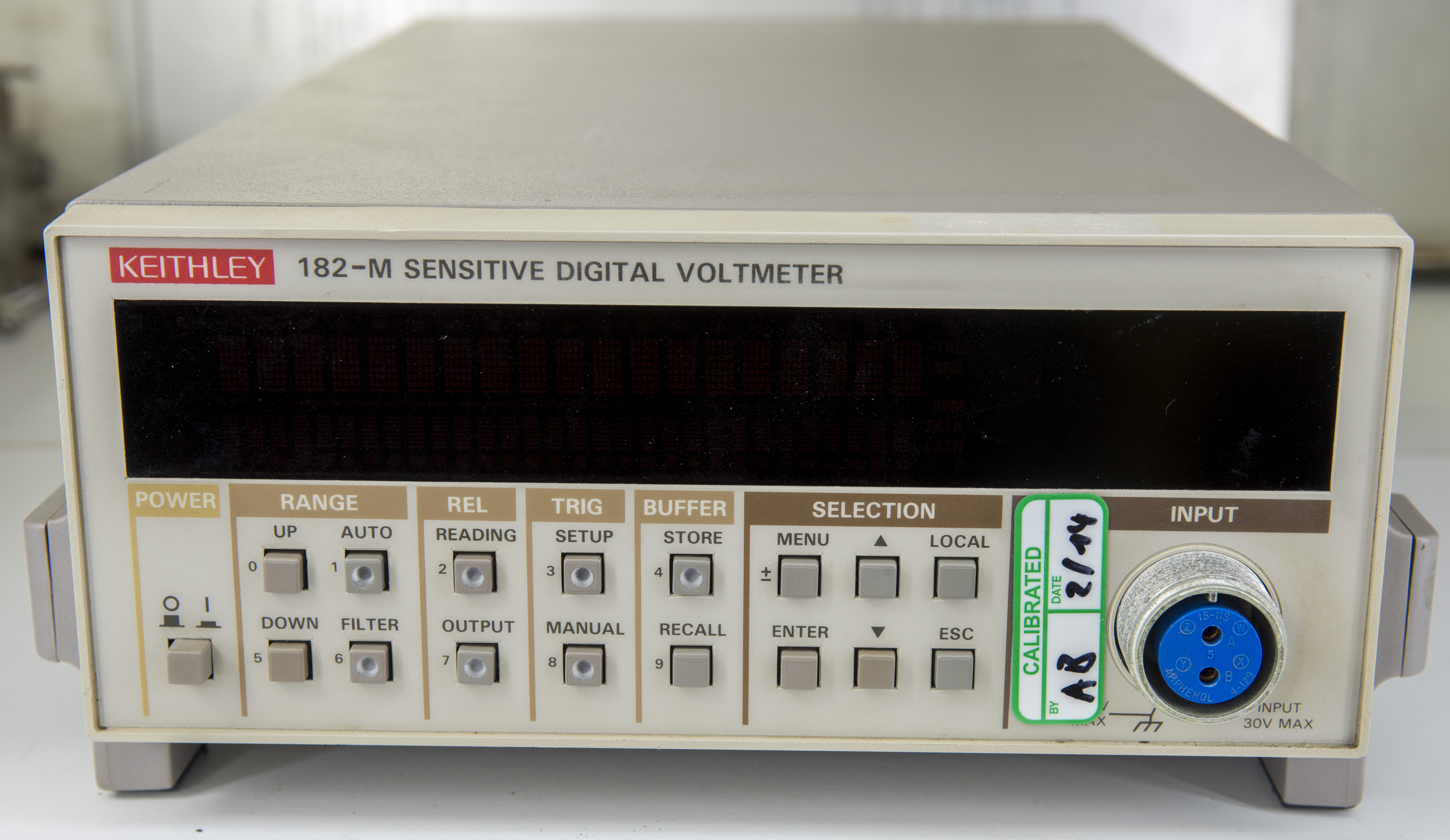
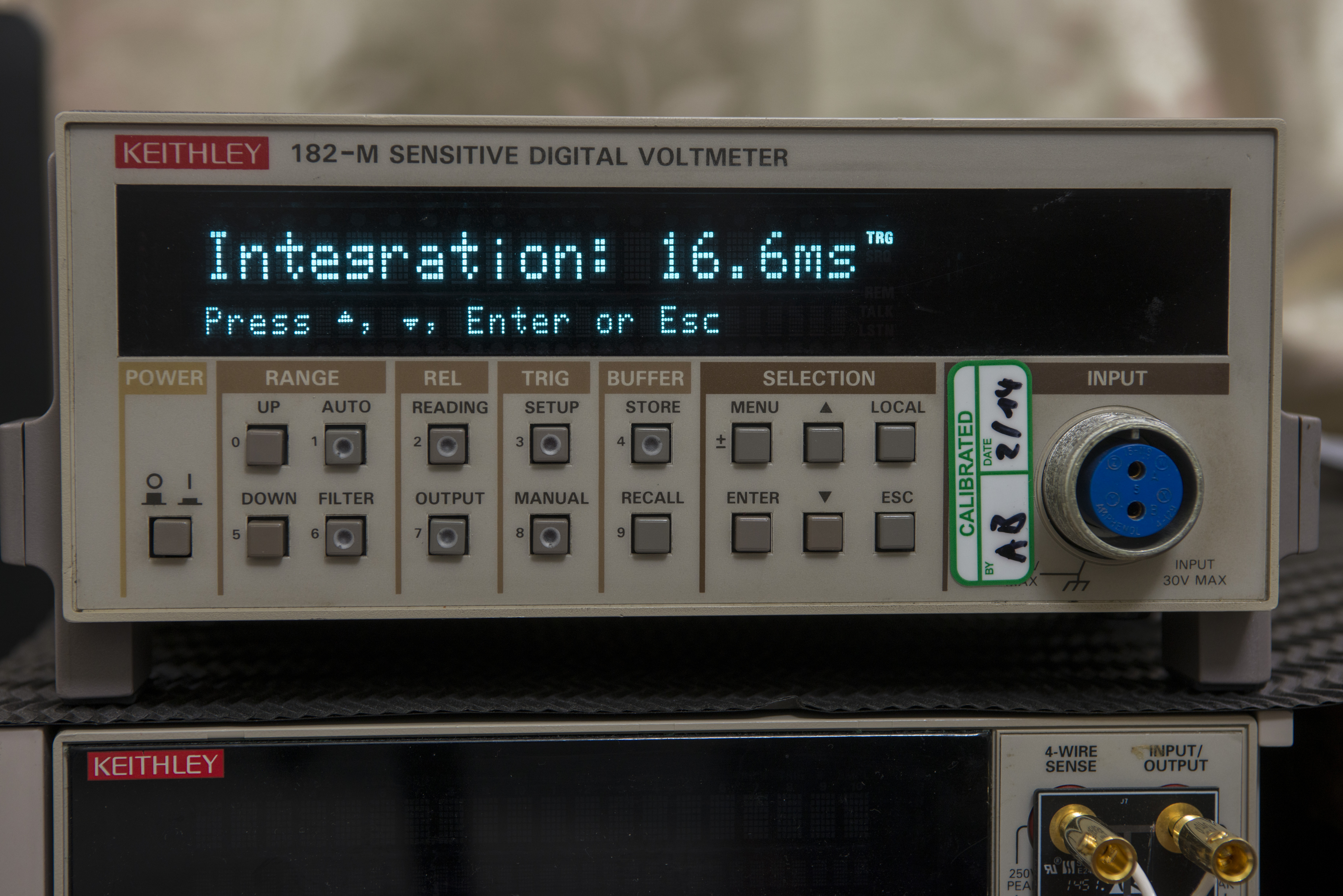
Meter is somewhat mix of old-style Keithley gear with square tactile buttons, and newer style with nice dot-matrix dual-line VFD screen and half-rack chassis form factor. While VFD screen looks like one used in Model 2001/2002/24xx/26xx series instruments, it’s not the same one. Perhaps Model 182 was first instrument to try this type of displays, before it was widely implemented for newer devices.
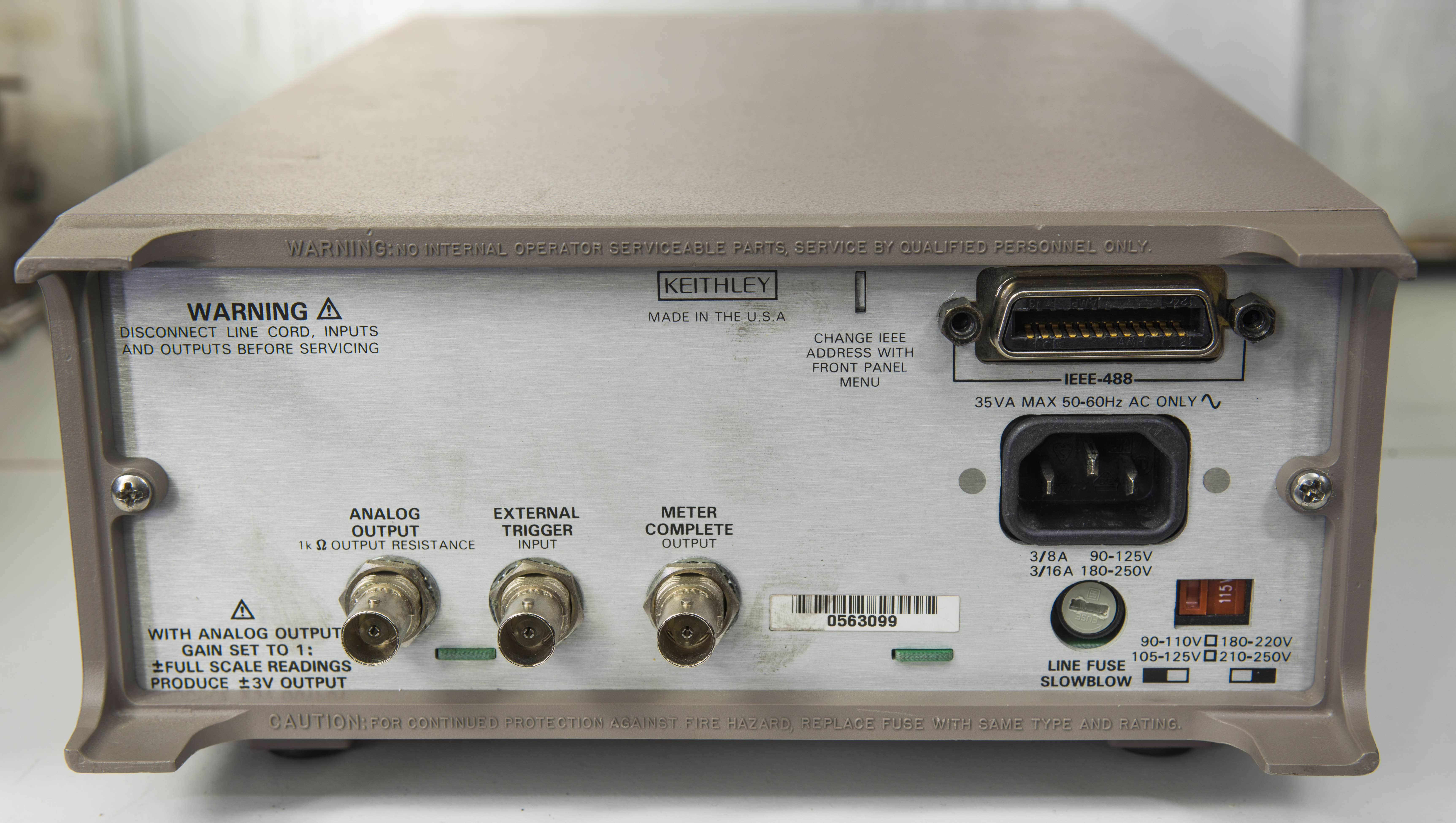
Rear panel have mains power input, line voltage switch, fuse holder, GPIB IEEE-488 port, and three BNC ports for analog output, external trigger input and meter complete output. There are no fans, vent holes or any external heatsinks in Model 182. One of reasons for this is to completely isolate internal boards from any possibility of airflow. This is part of design to avoid thermal EMF generation on low-voltage signal path.
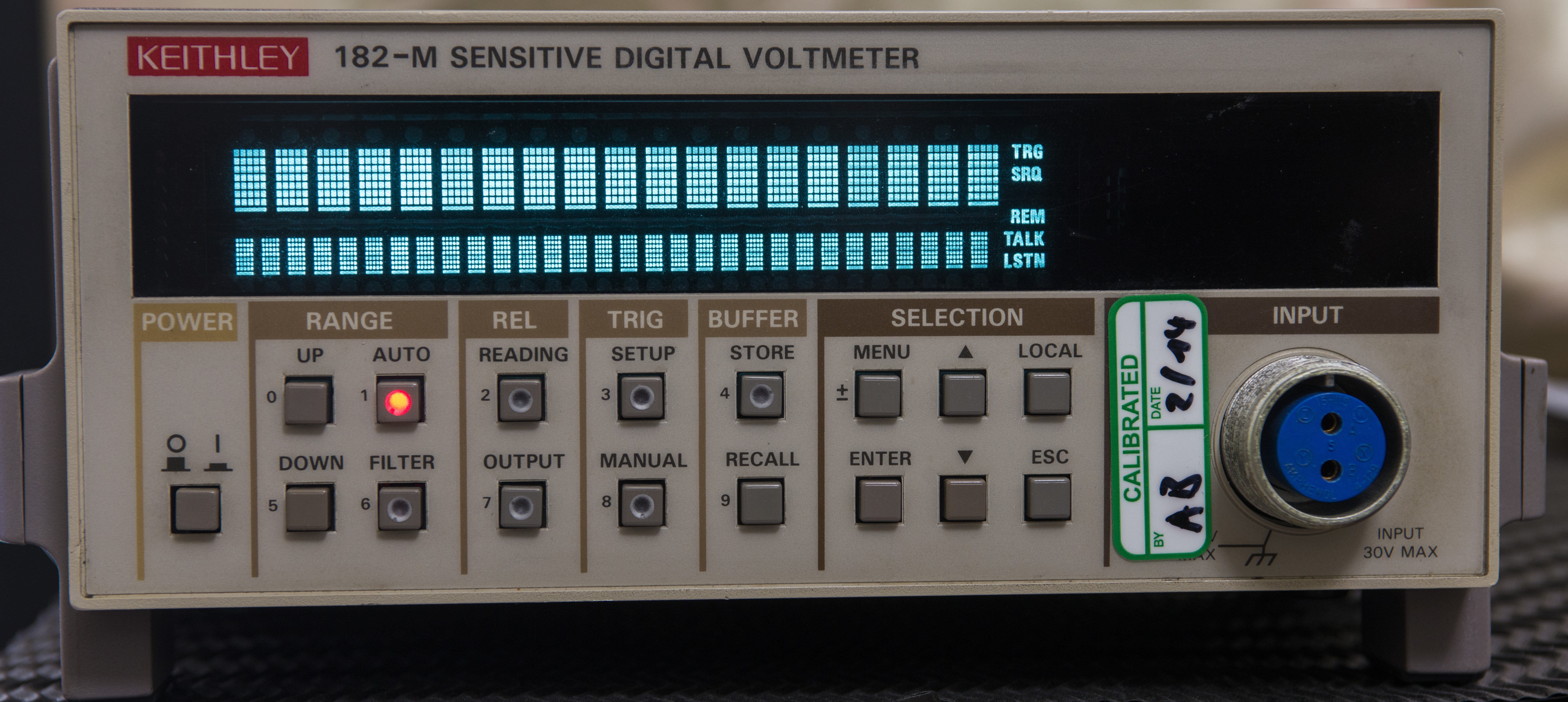
Our meter is very clean and in almost perfect condition, screen is bright. Always happy to see well cared instruments.
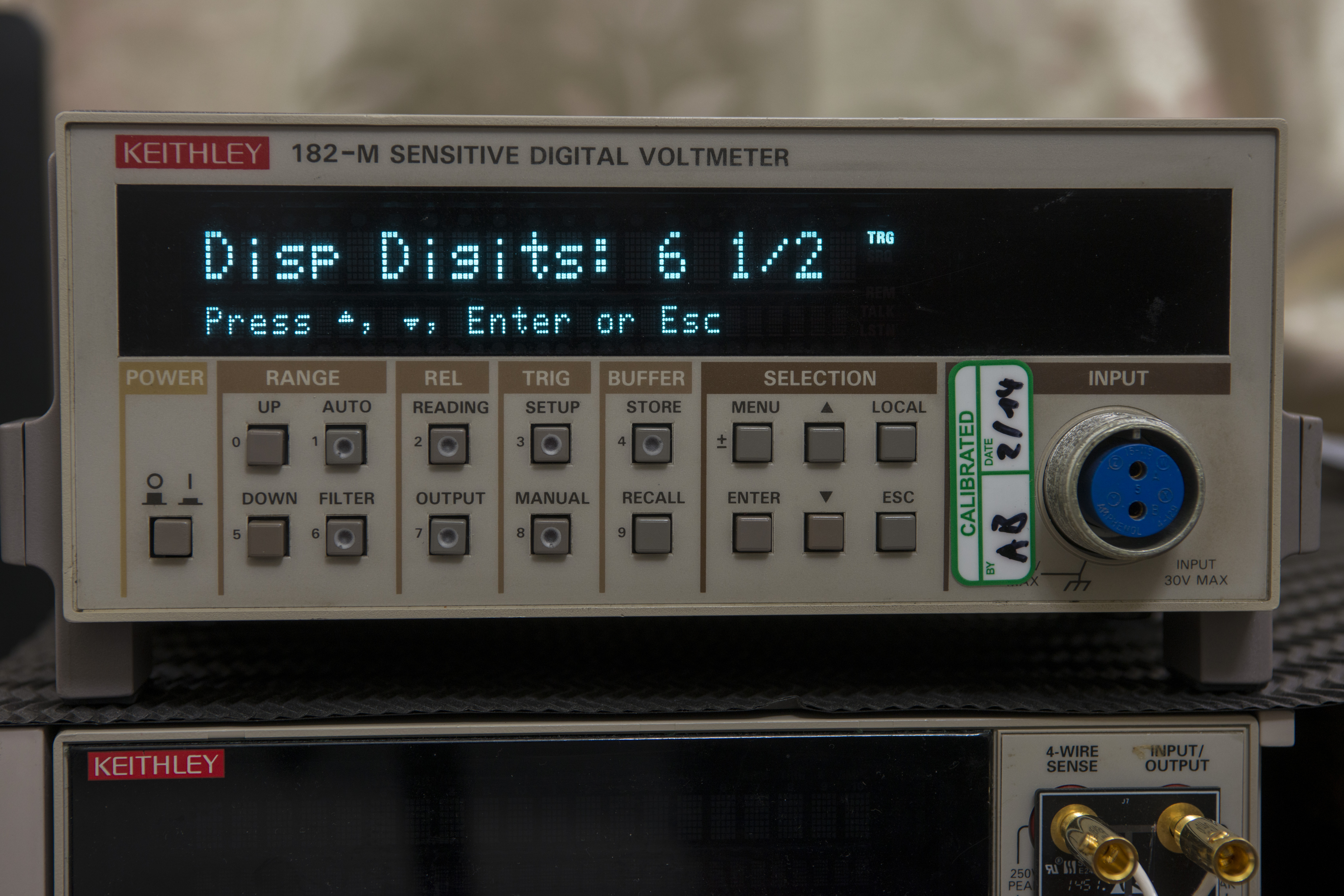
Menu system is simple and intuitive to use.
Interior & teardown
I will not go to full disassembly on this meter, as it’s still recently calibrated and I would like to keep it in spec. Even minor contamination of such sensitive analog circuitry parts can easily spoil calibration, so extra care with handling is required.
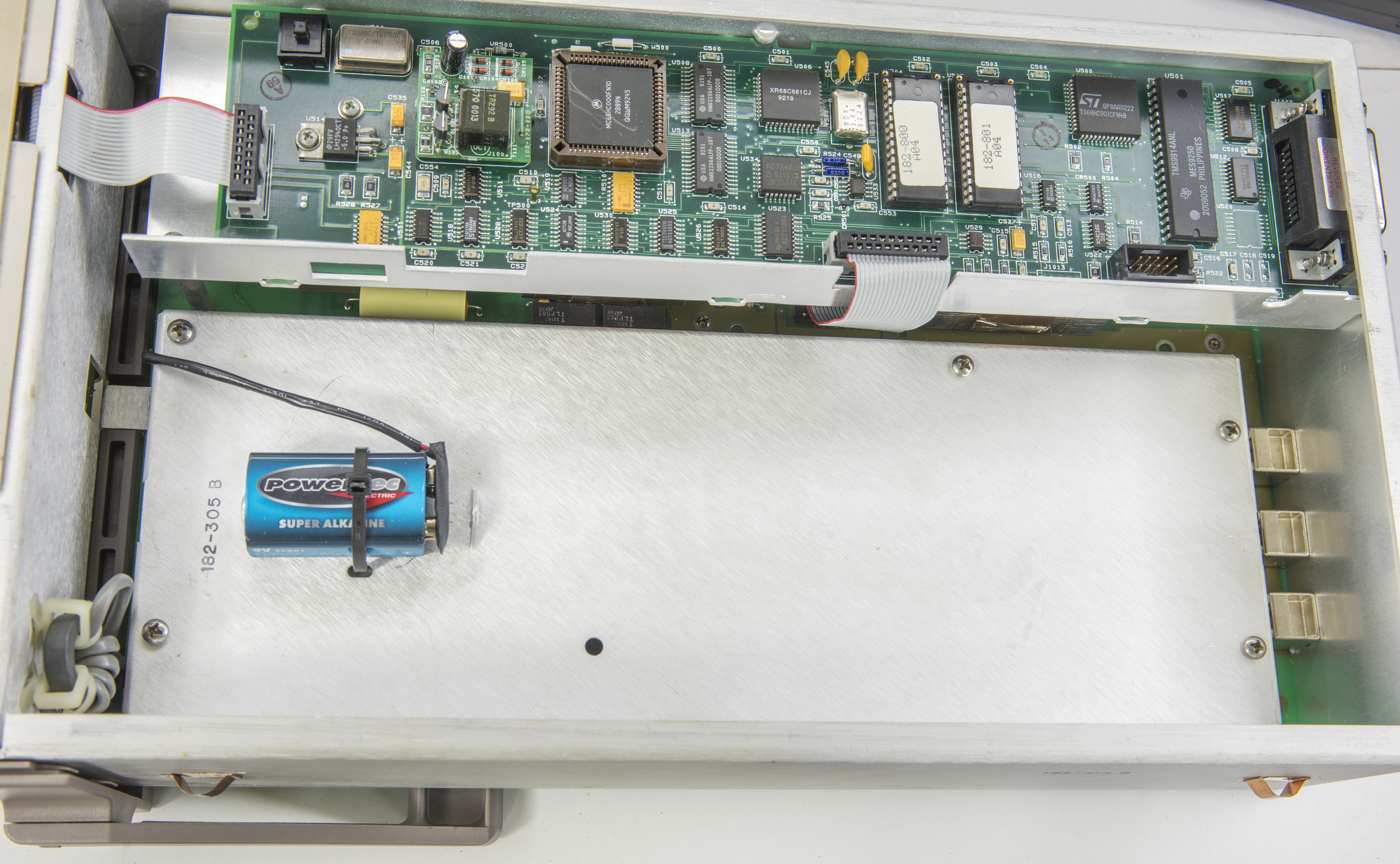
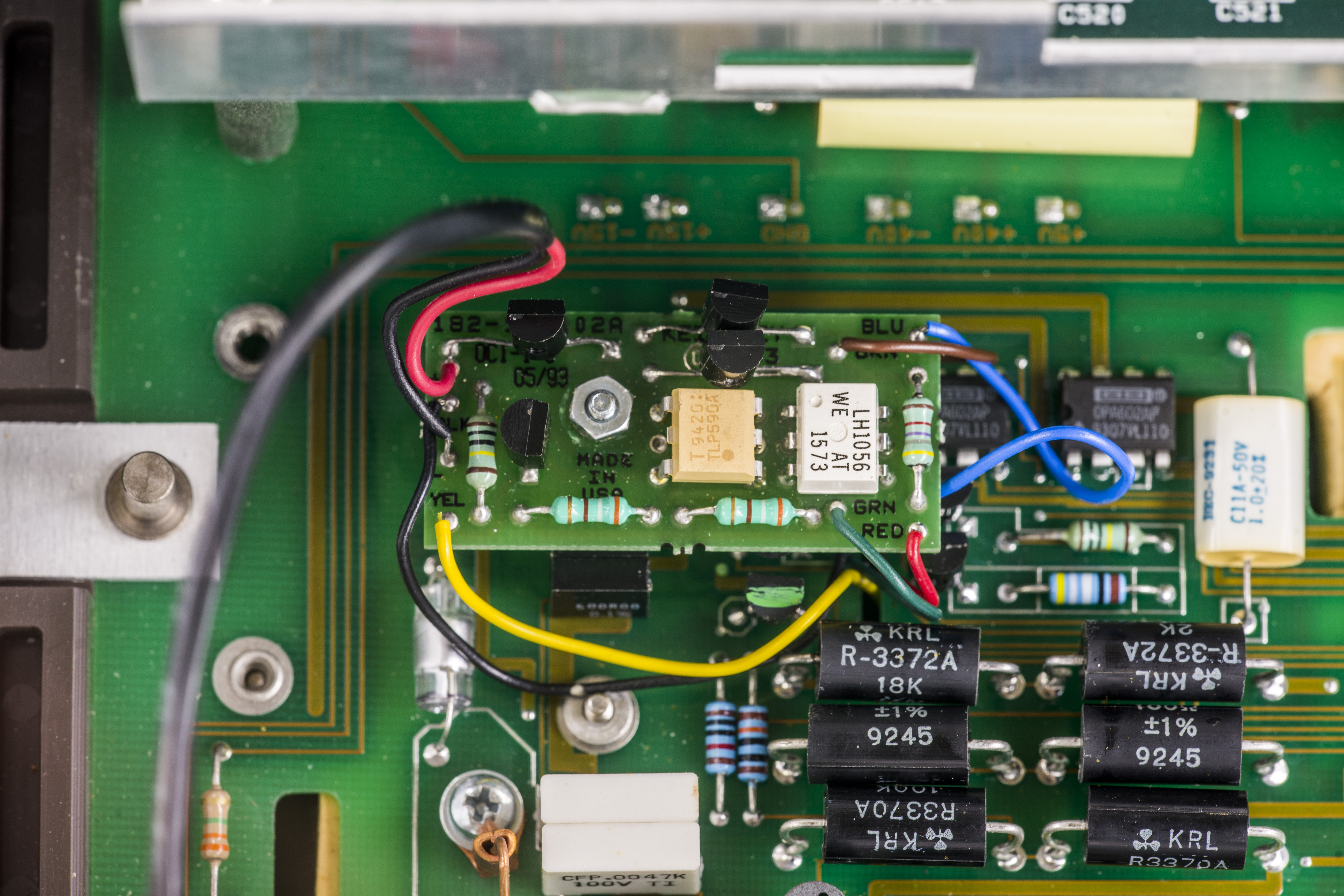
Model 182-M have extra 9V battery to power part of input front-end amplifier, so input impedance kept >10GΩ even if main voltmeter power switched off. Regular Model 182 does not have this part.
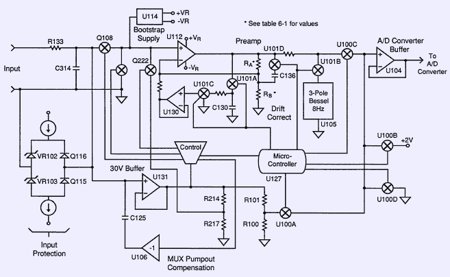
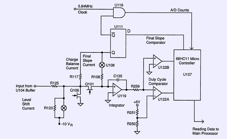
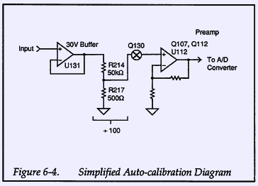
ADC is based on charge-balance multi-slope integration operation principle, similar to one used in most of 6½-digit and more bench DMMs. Manual have simplified ADC diagram, as below:
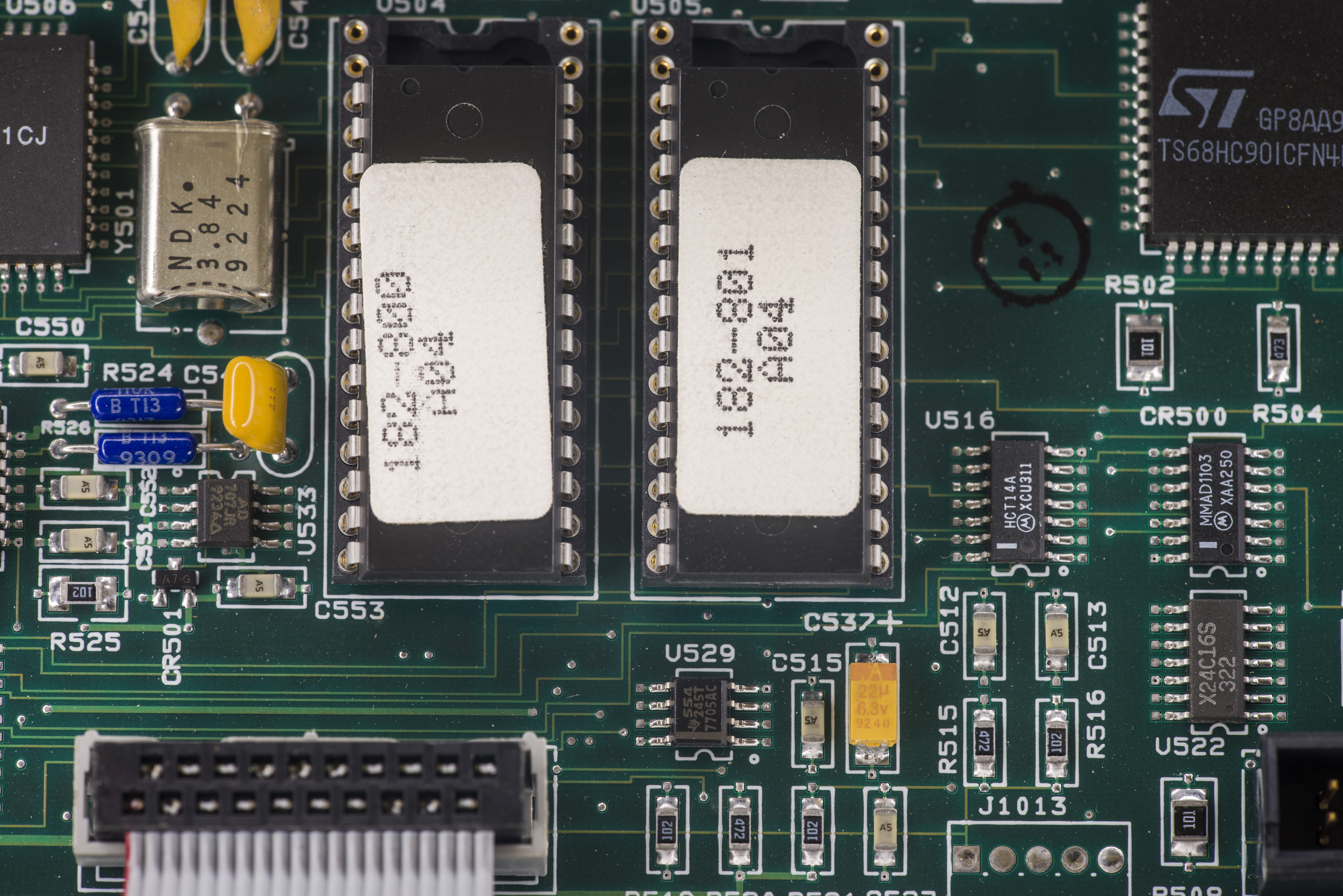
Digital board
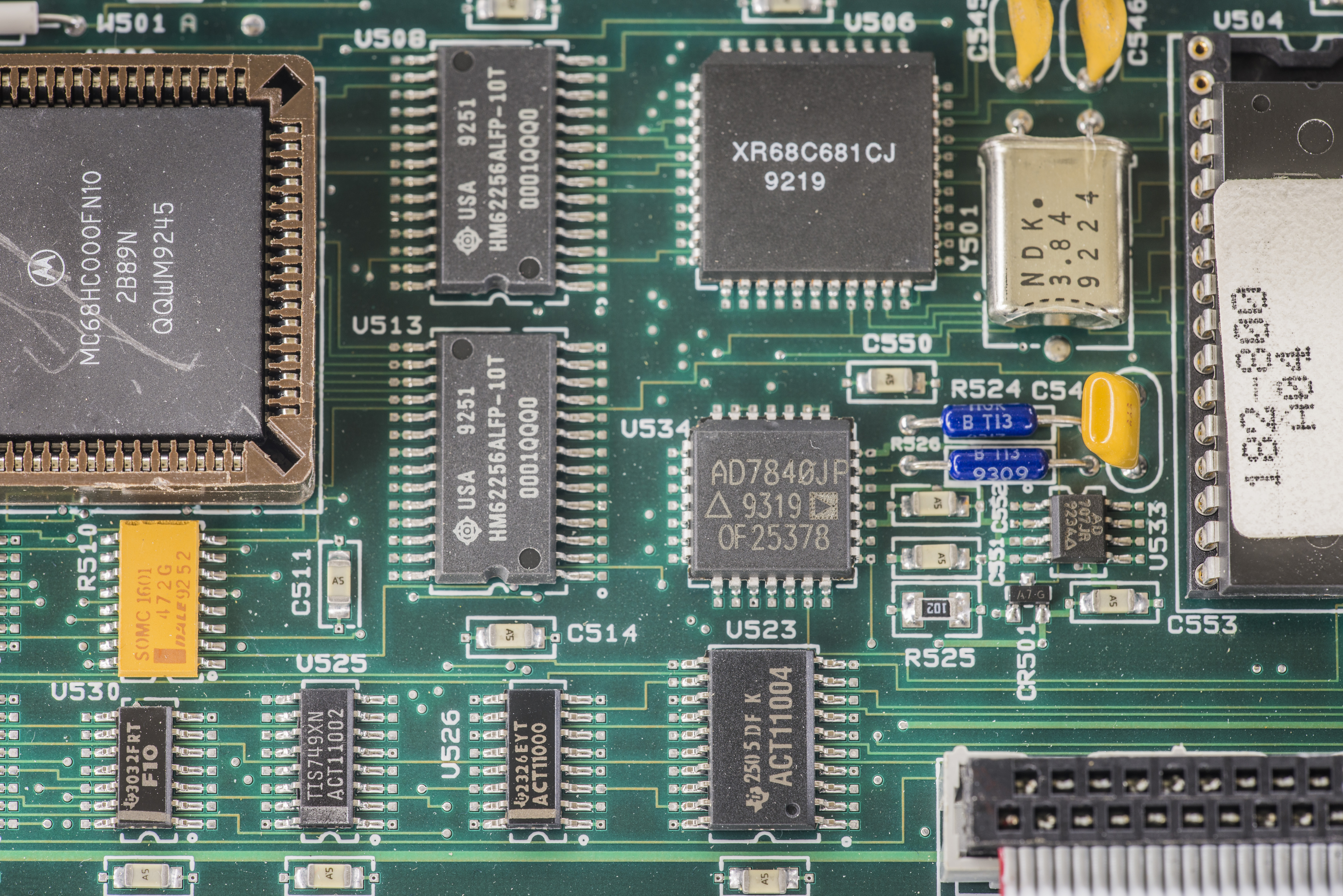
Main process is widely used Motorola MC68HC000FN10 in PLCC package, paired with Hitachi HM62256ALFP-10T SRAMs, forming totally 64KB of RAM. PLCC package U506 nearby is dual UART from EXAR, XR68C681CJ.
Analog Devices AD7840JP is analog output 14-bit DAC, with internal 3V buried zener reference. Reference temperature coeffient is ±60 ppm/K. Reference output is routed externally to DAC’s input, so it should not be too difficult to add external reference for this function, if better stability is required. Perhaps a future mod? :)
Analog Devices AD707JR nearby is ultralow drift output amplifier for DAC.
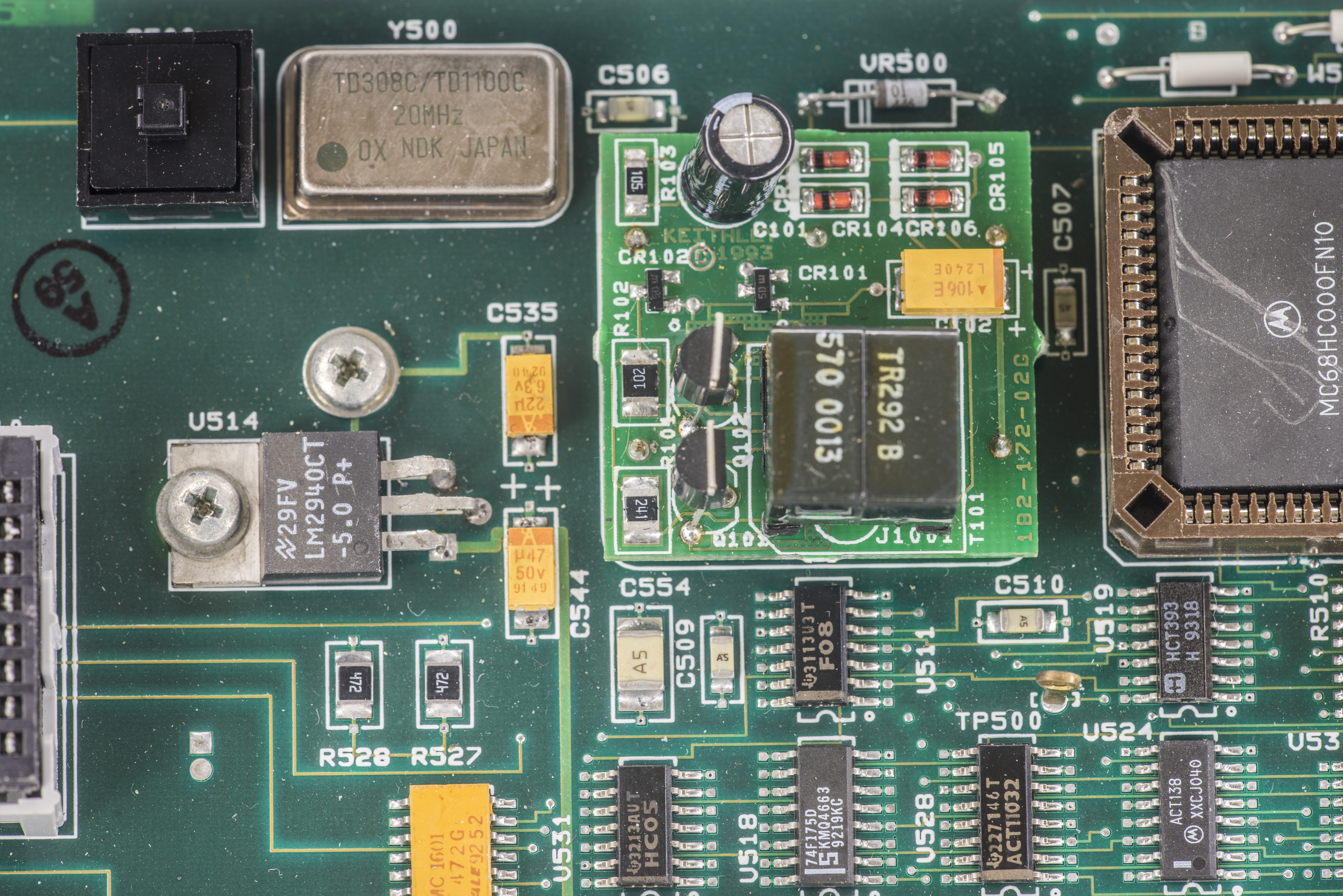
Digital board is powered from LM2940CT-5.0V LDO U514. There is also onboard DC-AC module for AC filament and +60VDC voltage generation. It’s exactly same as in other Keithley instruments with dual-line VFD. System clock is supplied from 20MHz oscillator Y500.
Power supply
Main power supply is rather interesting and using dual transformer approach. Mains transformer converts line voltage to low AC voltage for second transformer and also supply +7V to digital regulator.
Secondary transformer helps to prevent mains coupled noise from coming into analog circuits. This second transformer used to generate +15,-15,+5 and +40, -40 voltages. It also provide +15V power for LM399 ovenized reference.
Similar approached was adopted in modern instruments as well, such as Fluke 8508A and Keithley DMM7510.
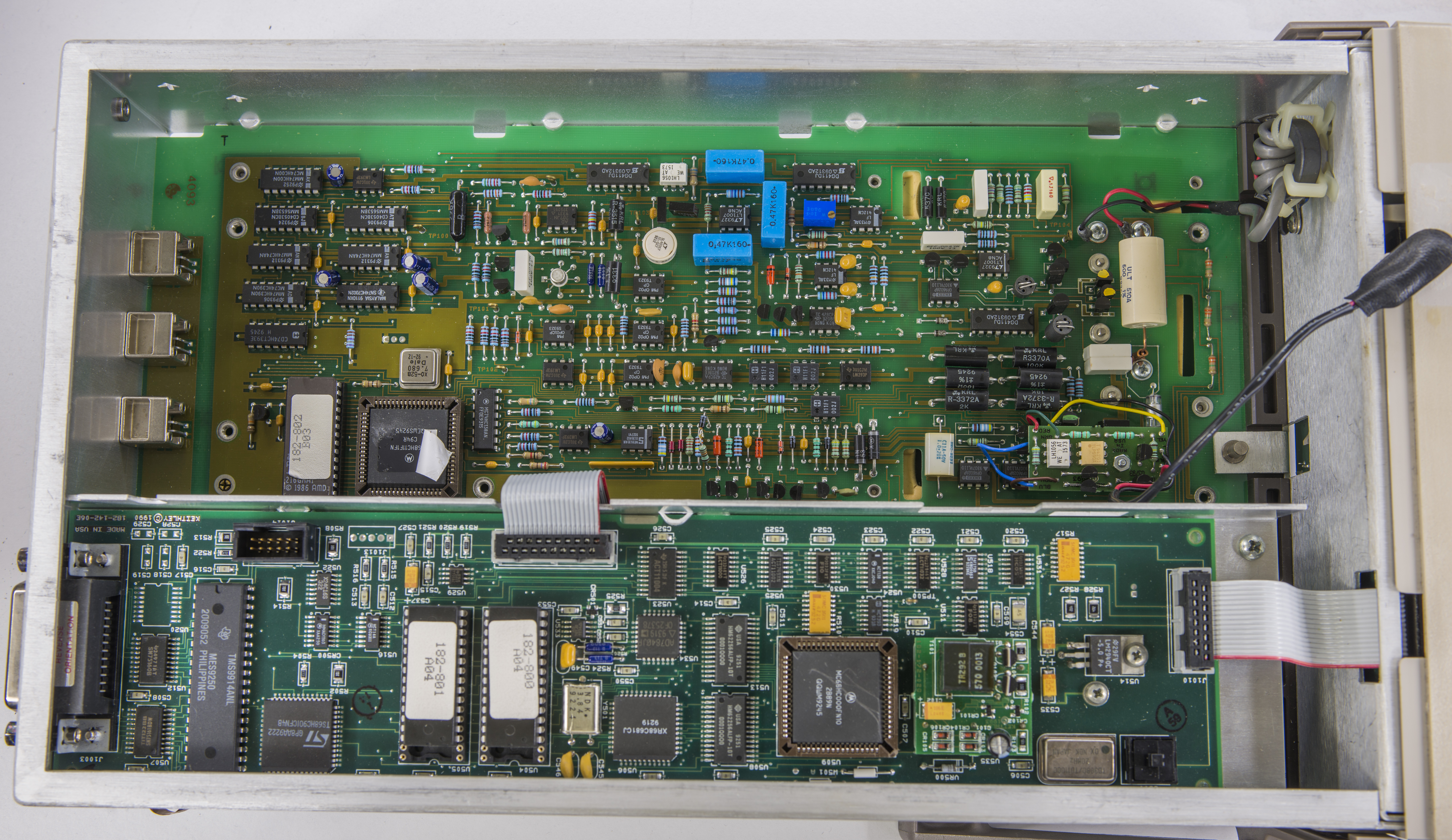
Analog board
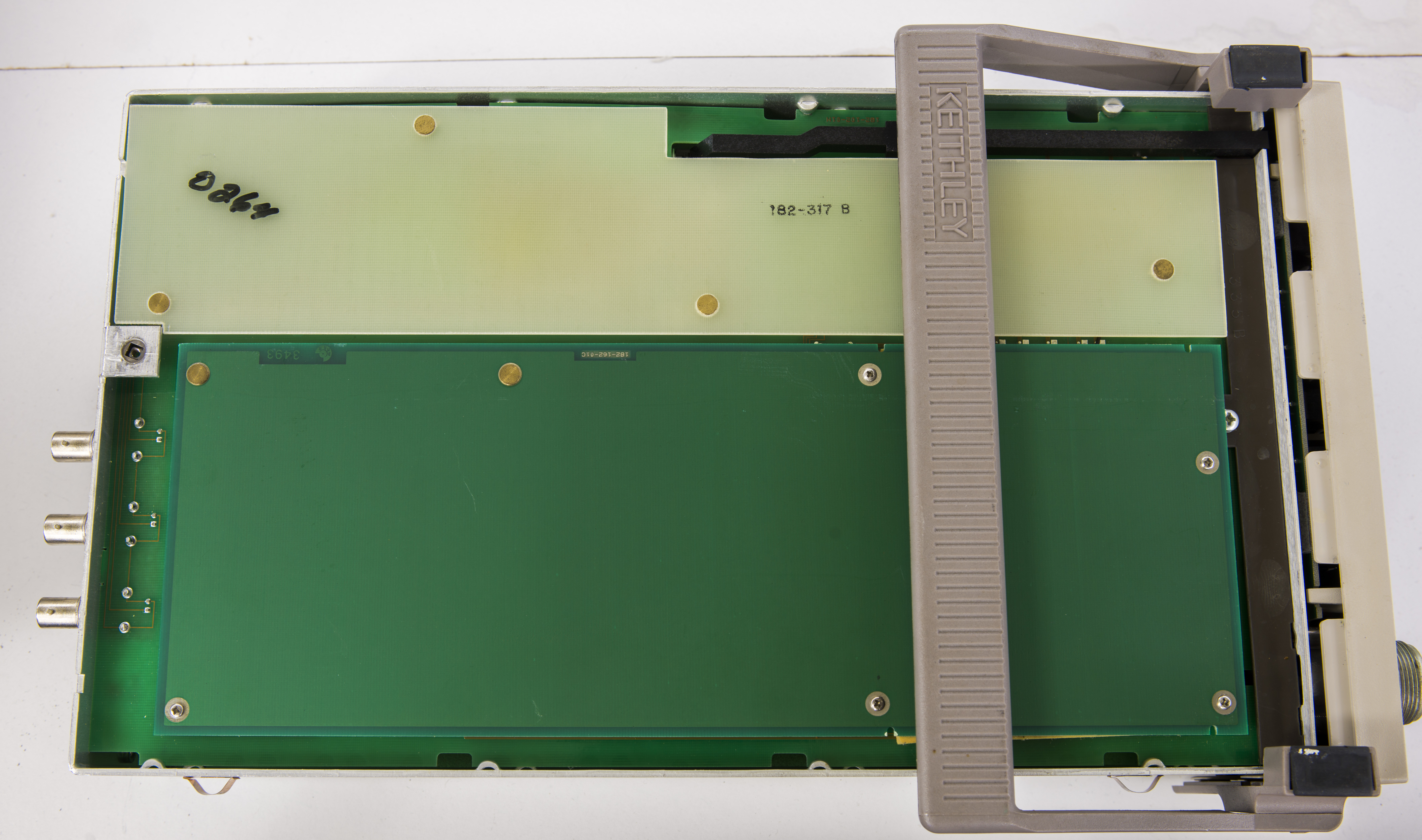
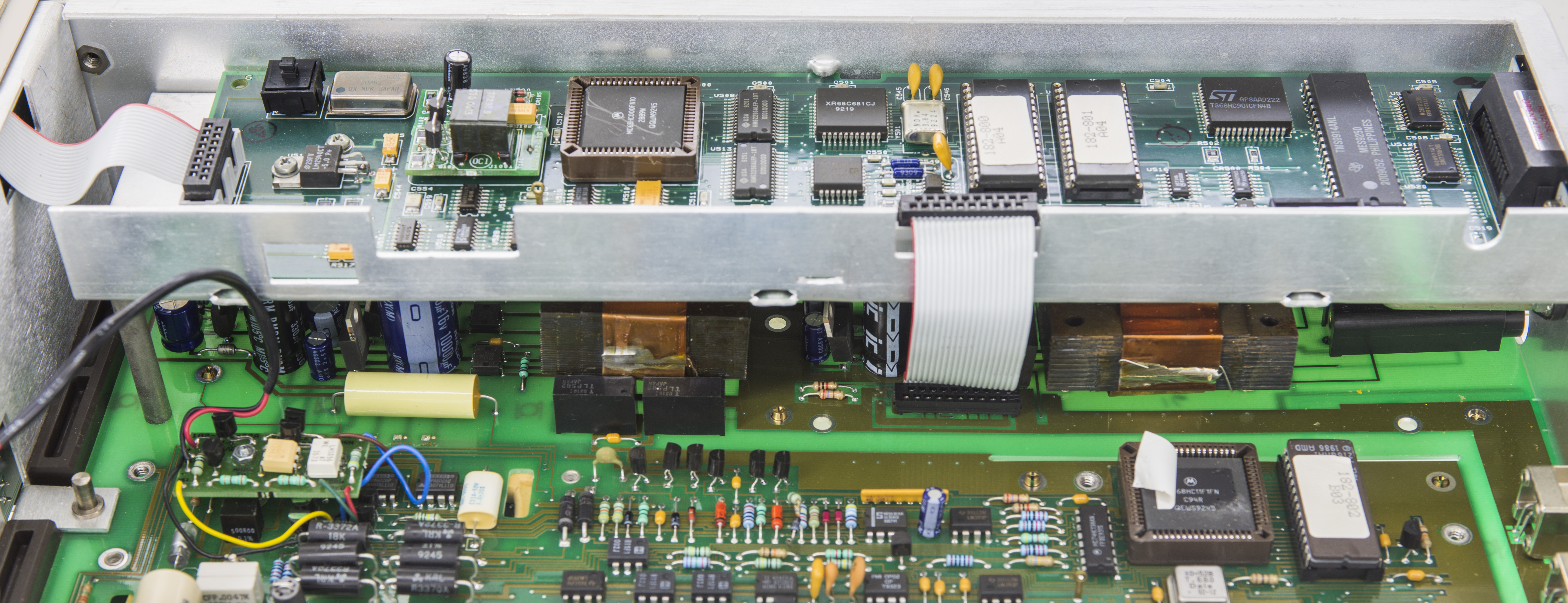
Whole analog circuit section is covered by aluminum shield to further isolate EMI, airflow and protect sensitive parts.
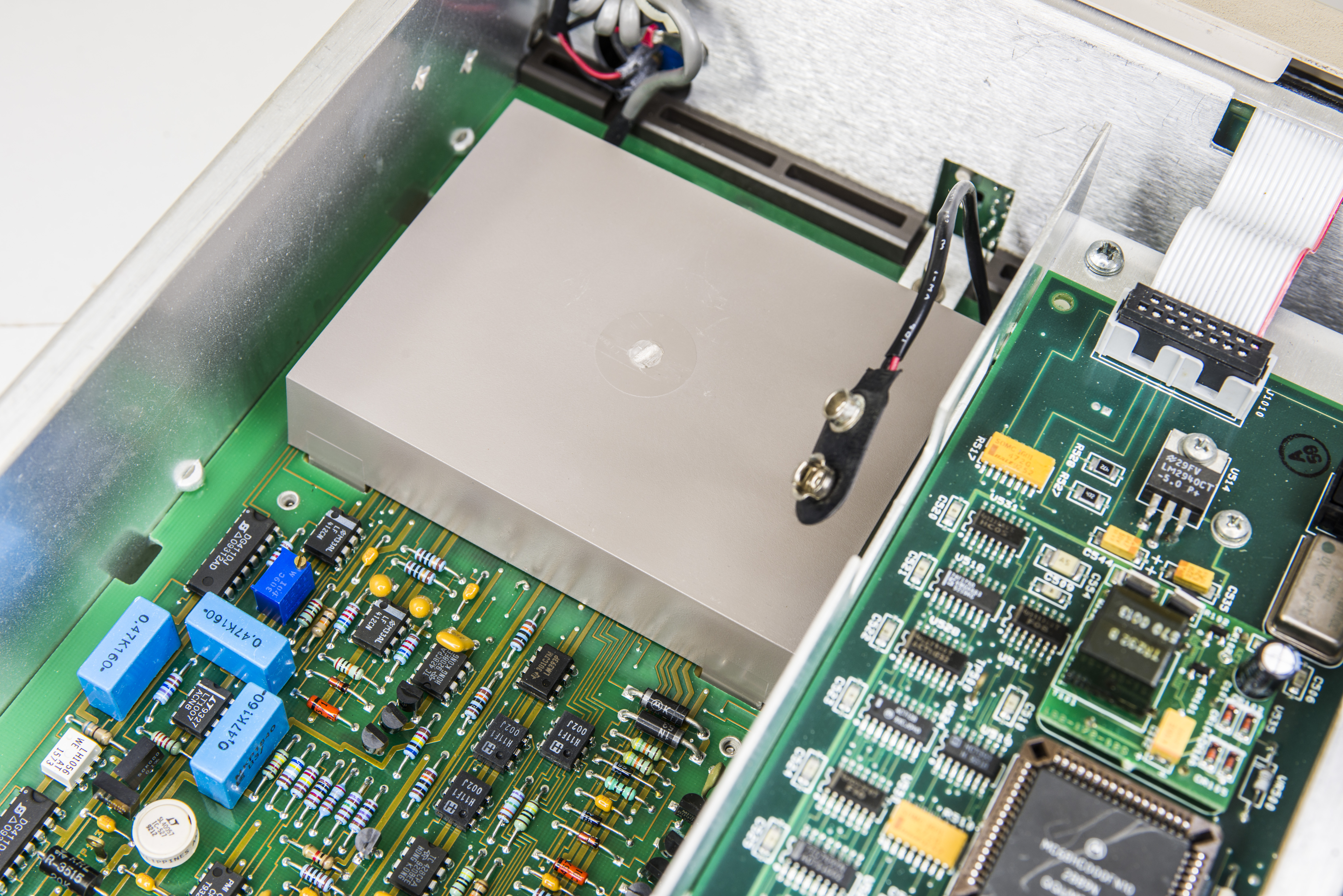
ADC controller is based on Motorola MCU MC68HC11F1N with its own ROM 182-802-B03. This 8-bit MCU have internal 1KB RAM, 8-channel 8-bit ADC and runs at 7.68MHz.
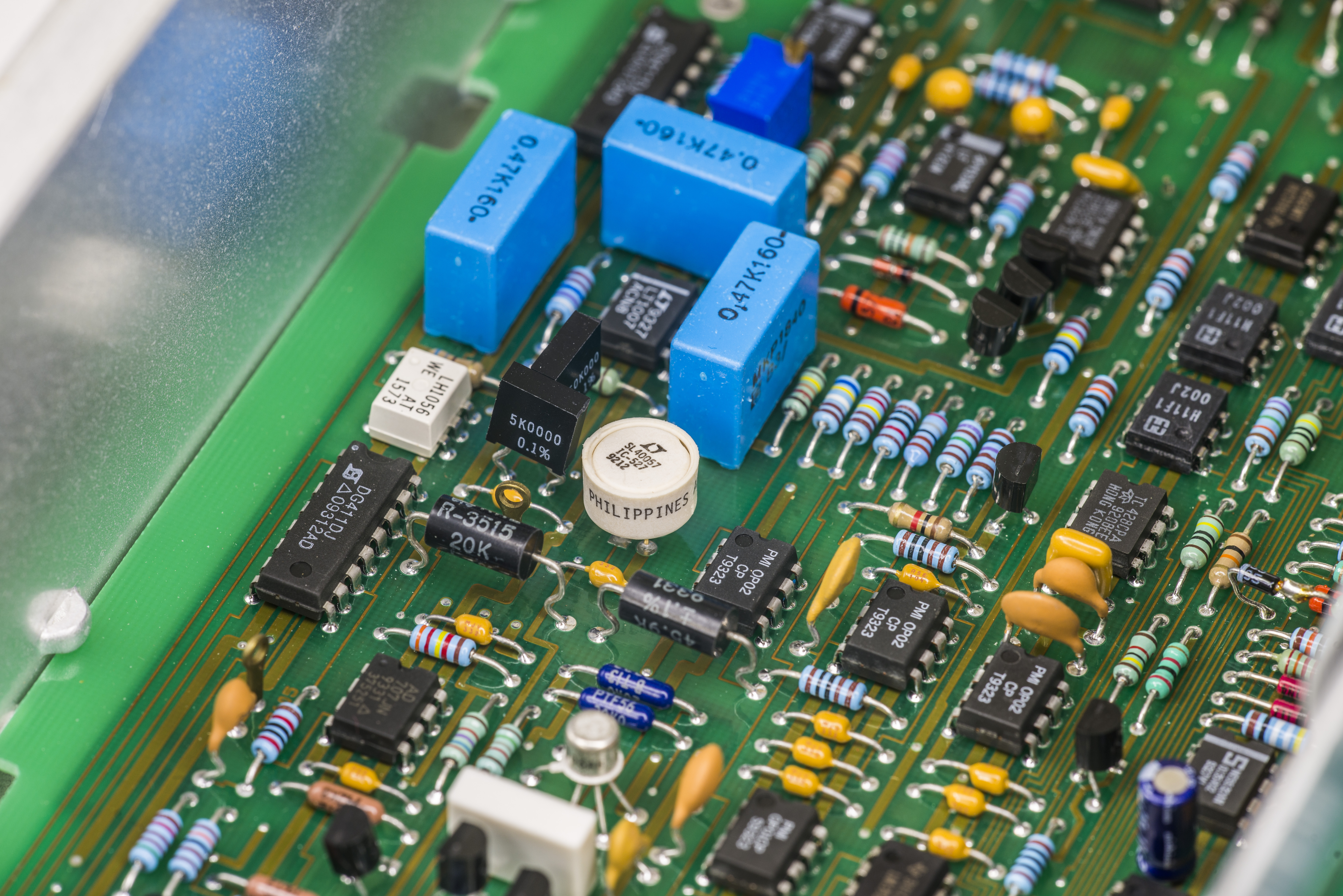
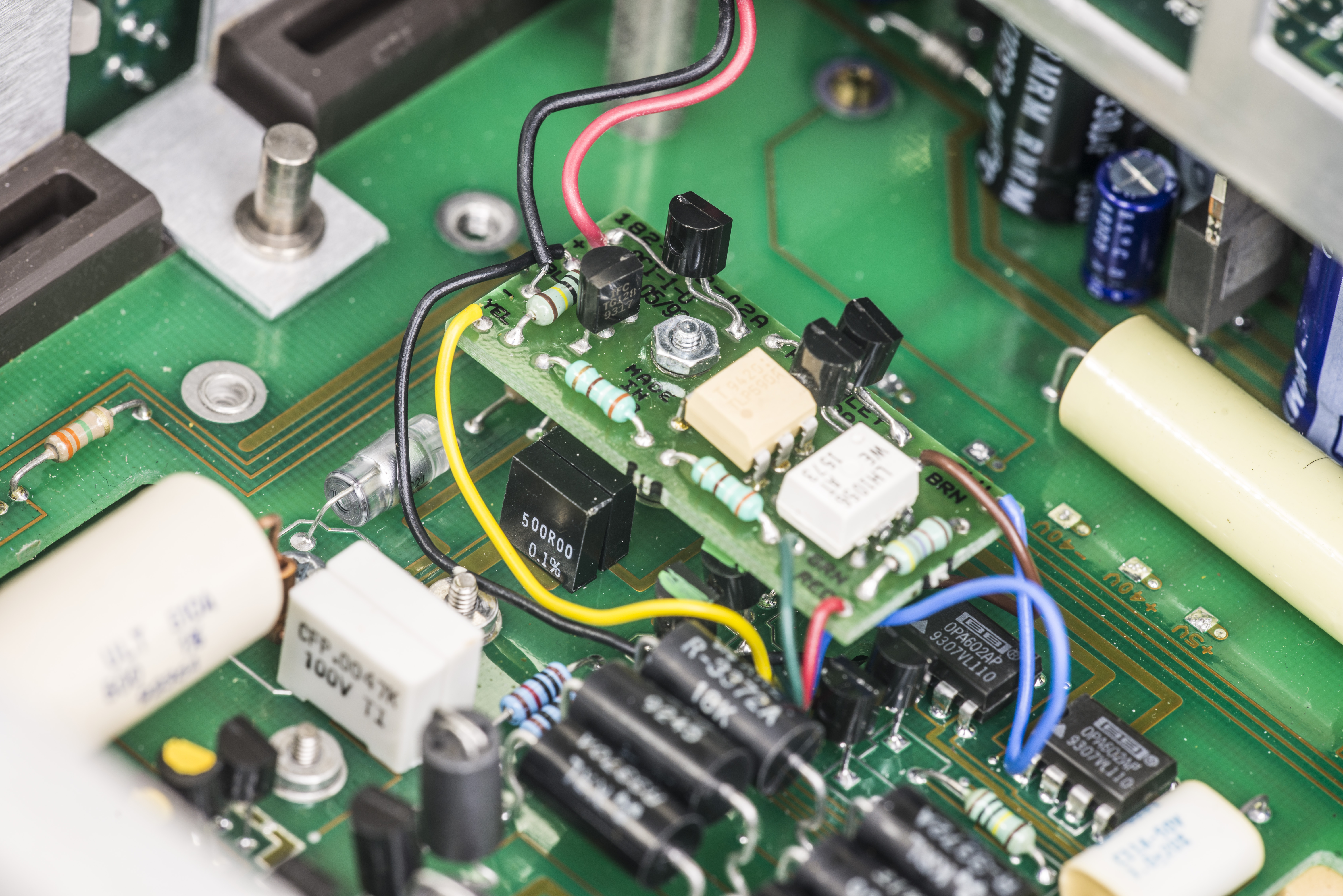
But it’s the front-end, where all the real analog magic happens..
The very front end section is even further covered by separate plastic cover. It a good example of system engineering required to implement highly sensitive analog circuits to get reliable performance and stability.
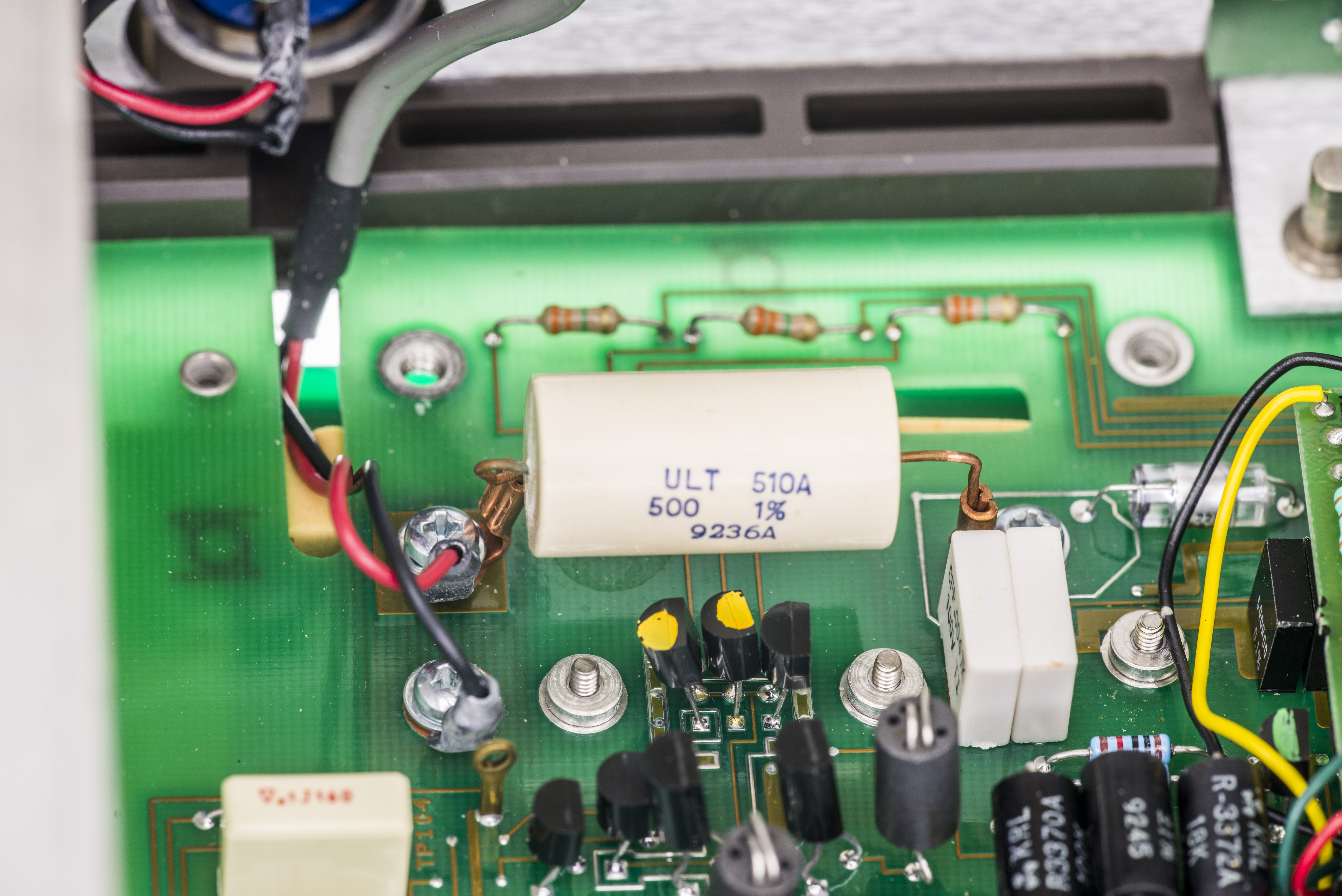
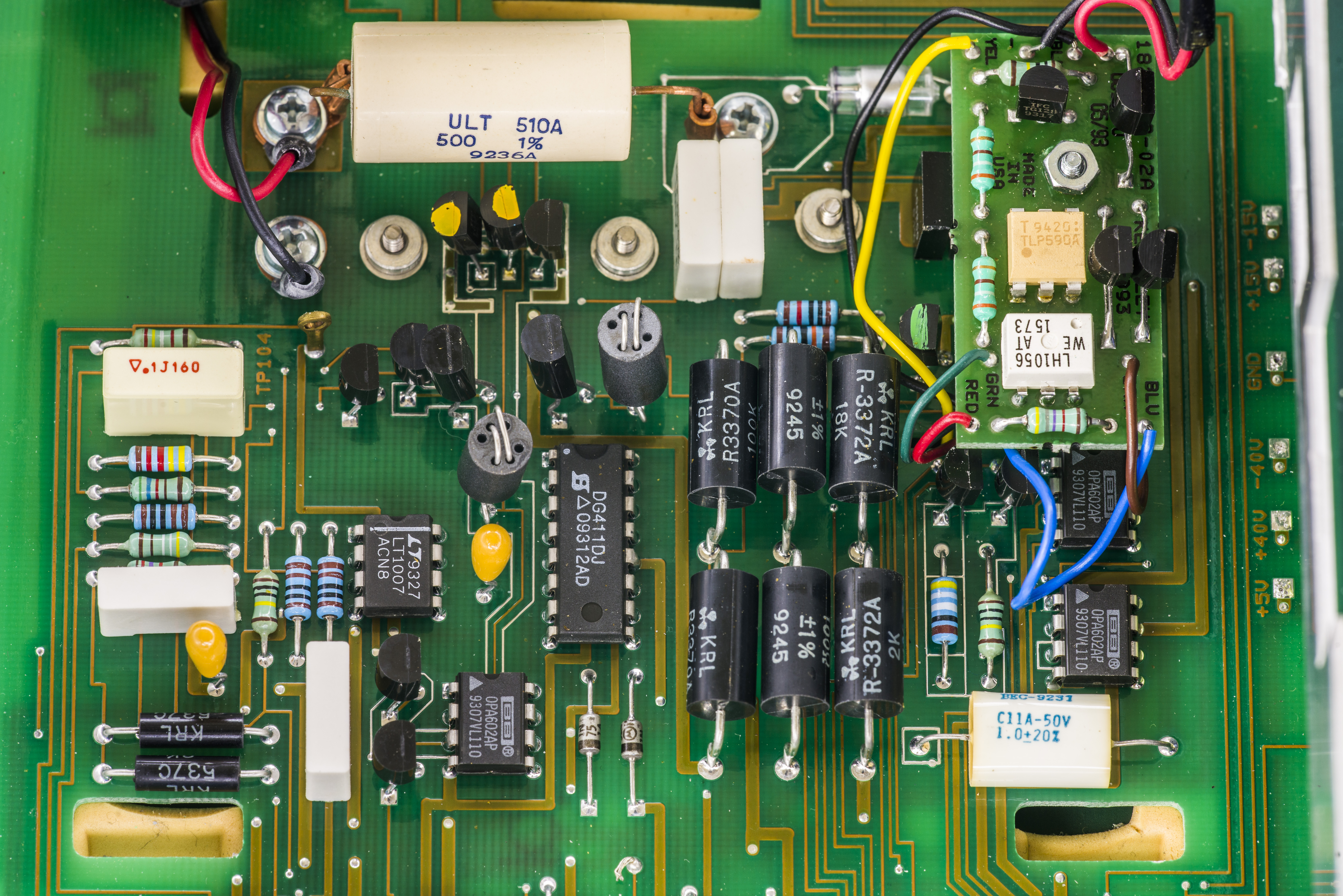
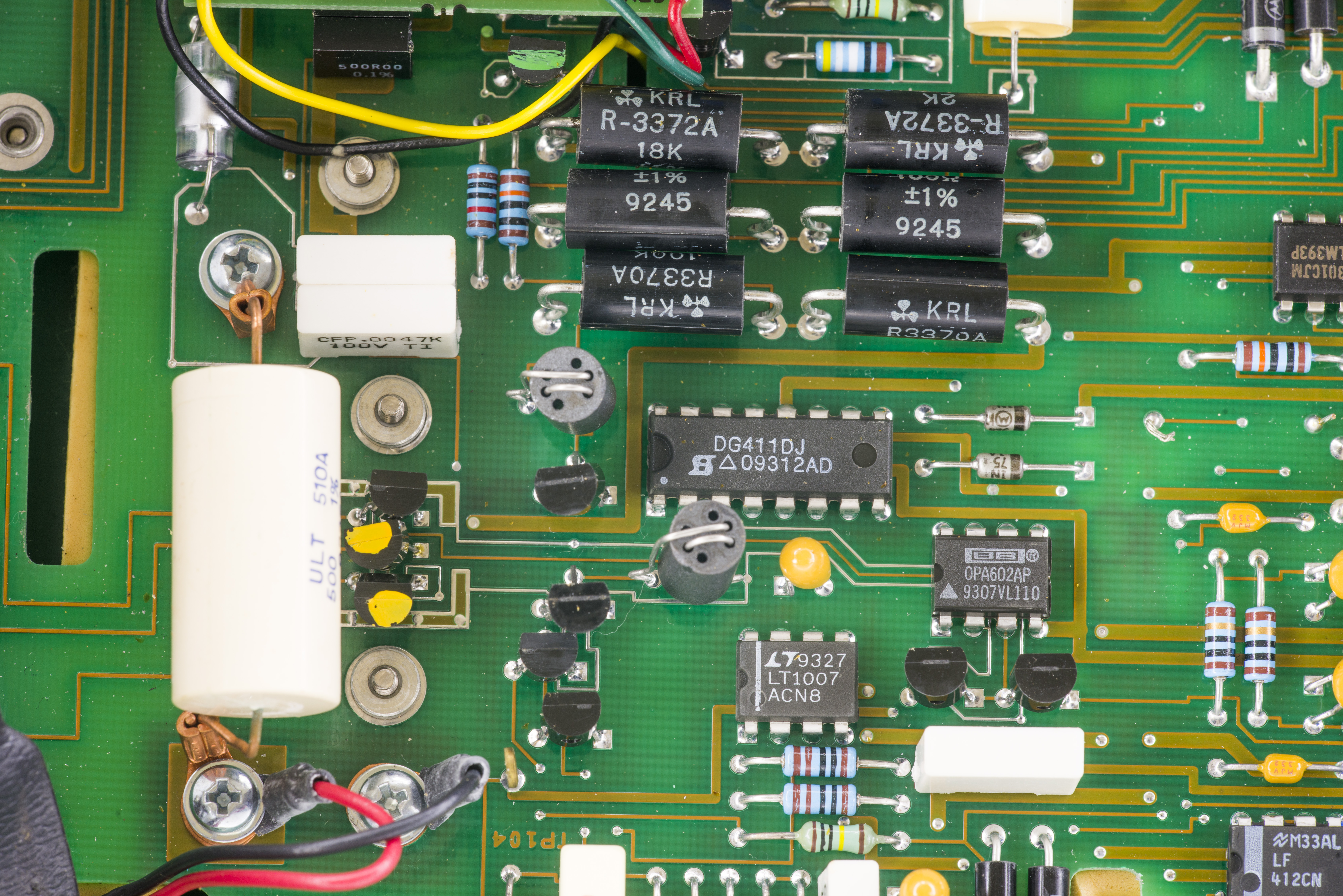
1% 500 Ω resistor sitting at the input terminal have copper leads and crimped to copper PCB connectors to avoid thermal EMF development. Input nets are further guarded by unmasked tracks on PCB. Small modular PCB is a separately powered front-end, so meter’s input impedance stays >10 GΩ even with mains power removed. This is special part of Model 182-M version only.
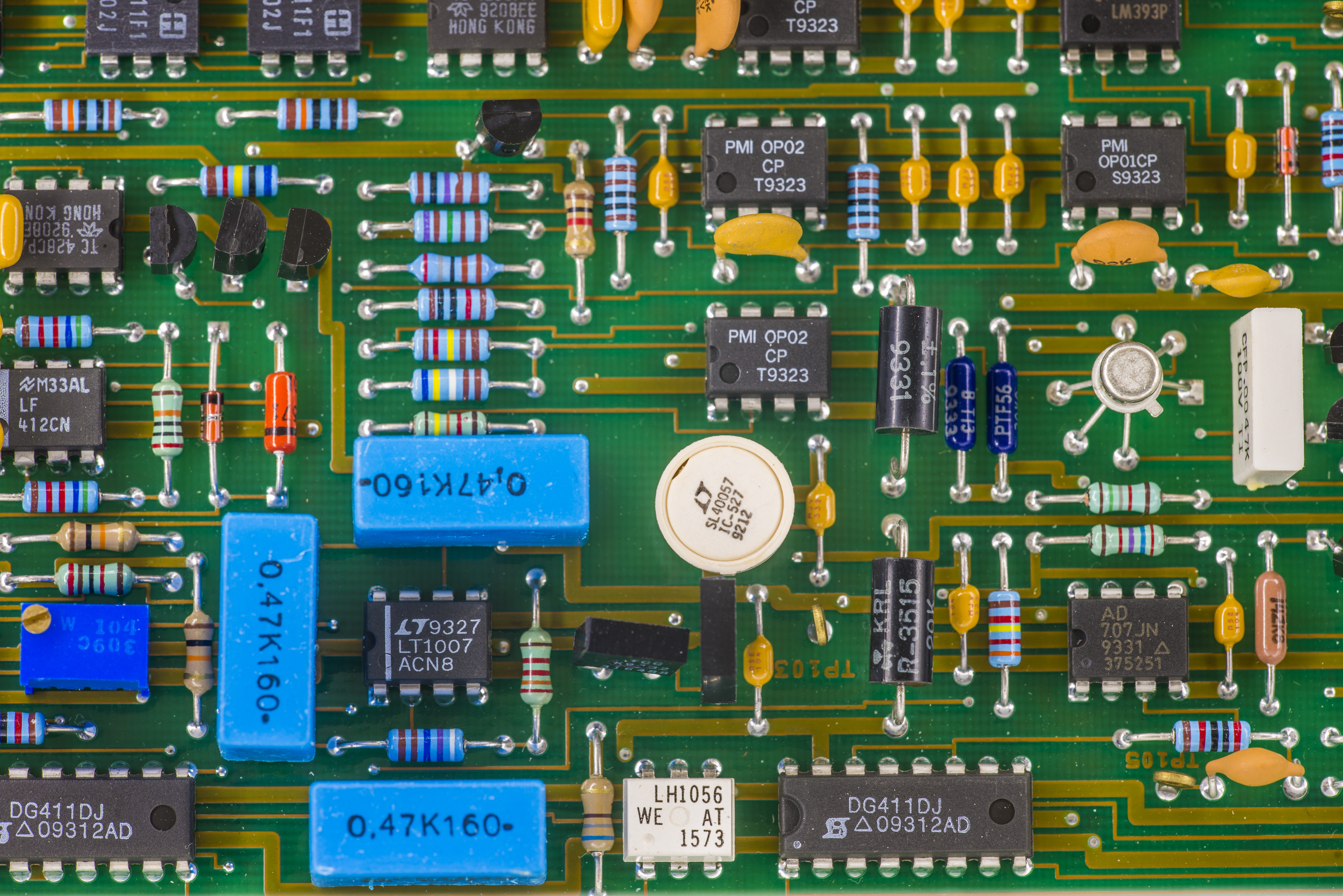
We can also spot some wirewound resistors, likely used to adjust gain for range switching. Most of opamps are Burr-Brown OPA602, but there is also LT1007 used as preamp
Voltage reference is selected LM399 ovenized 6.95V zener, similar to one used in Keithley Model 2000/2001 units.
There are few Vishay foil resistors as well, perhaps setting zener current.
Input port wire is pass thru filter ferrite to reduce RFI and noise a little, and crimped right down to PCB.

Firmware dumps

Keithley 182-M firmware A04, 27C512 ROM 182-800-A04 dump
Keithley 182-M firmware A04, 27C512 ROM 182-801-A04 dump
Keithley 182-M ADC firmware dump, 27C256 ROM 182-802-B03
Also captured calibration ROM from U522 X24C16S SO16 EEPROM. To do so hold CPU reset low, power on meter and read I2C chip with external programmer. I shorted CPU’s pin 20 to GND and hooked MiniPro TL866 programmer to perform this task.
Calibration EEPROM dump from I2C ROM
Calibration info
My meter come with this calibration data:
Date : 04/06/2015
Temperature : 20.3 ±2C
Used source : Datron 4808 AB038, calibration Sept 2014
| Signal level | 182-M Reading | Delta | MaxDelta | Deviation | Status |
| 0.19 VDC | 0.1899991 | 9.0E-07 | 0.000011 | 8.2 | PASS |
| 1.9 VDC | 1.899974 | 2.6E-05 | 0.000112 | 23.2 | PASS |
| 19.00 VDC | 18.99958 | 4.2E-04 | 0.00115 | 36.5 | PASS |
| -0.19 VDC | -0.1899981 | -1.9E-06 | 0.000011 | -17.3 | PASS |
| -1.9 VDC | -1.899965 | -3.5E-05 | 0.000112 | -31.3 | PASS |
| -19 VDC | -18.99943 | -5.7E-04 | 0.00115 | -49.6 | PASS |
| 19 mVDC | 0.018999973 | 2.7E-08 | 0.00000116 | 2.3 | PASS |
| 1.9 mVDC | 0.001899971 | 2.9E-08 | 0.000000141 | 20.6 | PASS |
| -19 mVDC | -0.018999959 | -4.1E-08 | 0.00000116 | -3.5 | PASS |
| -1.9 mVDC | -0.001899938 | -6.2E-08 | 0.000000141 | -44.0 | PASS |
It’s unclear to me why calibration was done at 20C, instead of standard 23C, like meter’s specification and manual.
Calibration for Model 182 for 3mV and 30mV ranges is internal ratiometric, and for higher ranges direct. Calibration source must be able to provide 300mV, 3V and 30V signals.
Calibration constants can be also read by sending GPIB command U11X.
Output on my meter is as below
CAL+4.826974E-01,+4.826965E-01,-1.136970E-07,+4.852434E-01,+4.852453E-01,-9.680330E-08,+4.811439E-01,+4.811463E-01,-3.695733E-07,+4.801486E-01,+4.801503E-01,-3.498665E-06,+4.364472E-01,+4.364473E-01,-7.152183E-04,+1.009753E+00,+3.296010E+00,+4.000000E+00
Python application to gather data from Keithley Model 182-M
Model 182 does not use SCPI language common in more recent instruments, and rely on abbreviated commands instead.
Command reference shown below in table
| Command | Function | ||
| B0 | 5½-digit resolution | B2 | 3½-digit resolution |
| B1 | 6½-digit resolution | B3 | 4½-digit resolution |
| D0 | Filter damping off | D1 | Filter damping on |
| N0 | Filters off | N1 | Filters on |
| O0 | Analog Filter off | O1 | Analog Filter on |
| R0 | Enable Autorange | R1 | 3mV range |
| R2 | 30mV range | R3 | 300mV range |
| R4 | 3V range | R5 | 30V range |
| R6 | N/A | R7 | N/A |
| R8 | Disable Autorange | ||
| S0 | Line-cycle integration rate | S1 | Medium integration rate |
| S2 | Fast integration rate | X | Execute other commands |
| Z0 | Reading relative off | Z1 | Reading relative on |
| Z2,value | Use value for relative | Z3 | Use previous value |
To execute command, follow “Command”+X syntax. For example R4X will set meter to 3V measurement range
Meter returns reading strings, with typical format : NDCV+1.234567E+00
It’s also possible to program multiple commands at once, for example B1R1S0X will set 6½-digit resolution, 3mV range and line-cycle integration rate.
# xDevs.com Python test GPIB app for Keithley 182M
# http://xdevs.com/review/k182m/
import sys
import Gpib
import time

with open('3mv.csv', 'wb') as o:

    inst = Gpib.Gpib(0,1) # Instrument GPIB Address = 17
    inst.clear()
    o.write("k182;\r\n")
    min = 0
    inst.write("Y2B1F0D1P3Q1000O1N0R1S2W0X")
    inst.write("Y2B1F0D1P3Q1000O1N1R1S2W0X")
    while min <= 1000:
        min+=1
        inst.write("X")
        data = inst.read()
        val = data.split('NDCV')
        time.sleep(1)
        print("%s" % val[1])
        o.write(";%s" % val[1])
        if (min == 1000):
            min = 0
This program collects data every sample with meter configuration at 3mV range, analog filter on, digital filter slow, with trigger delay 1s.
Performance verification
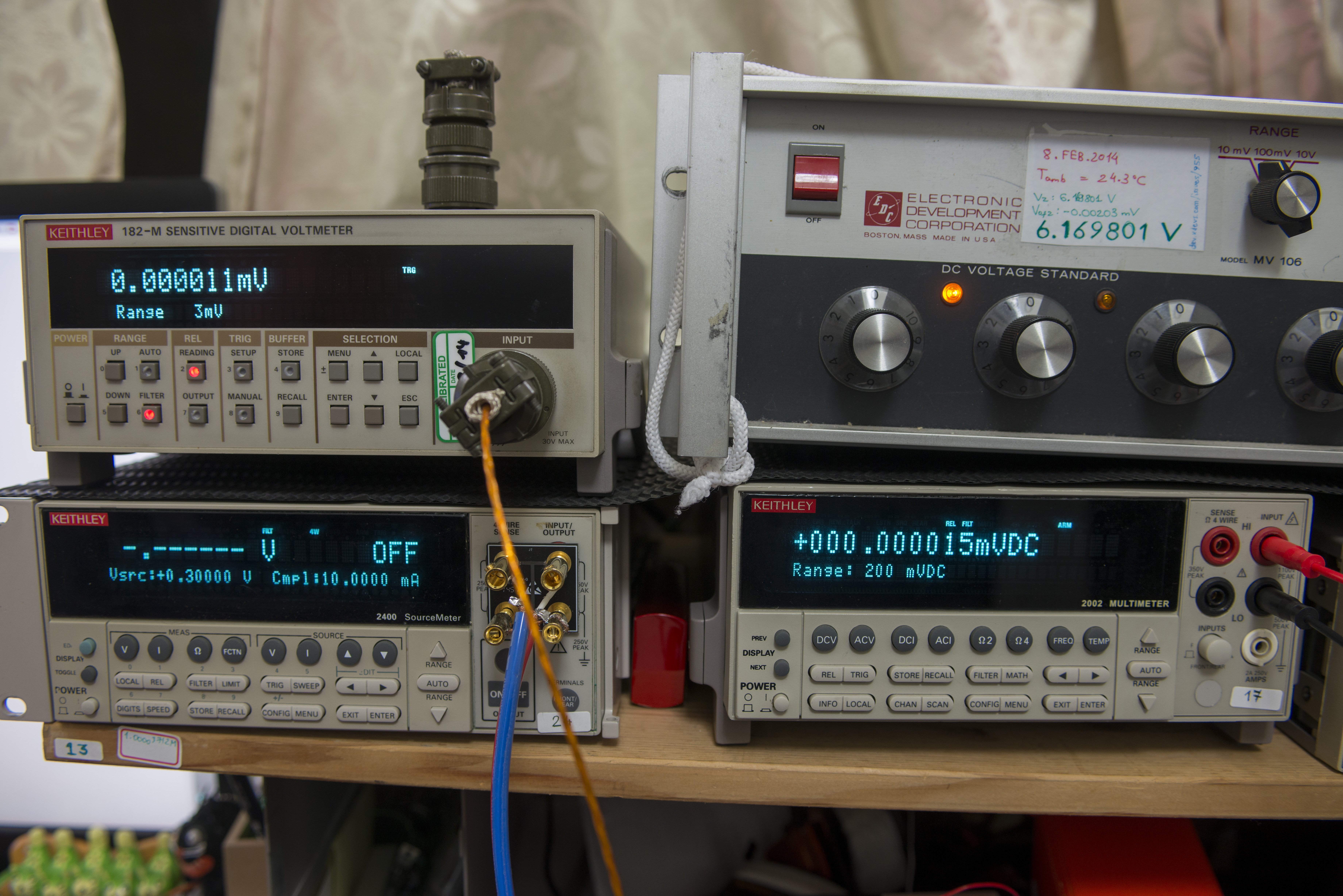
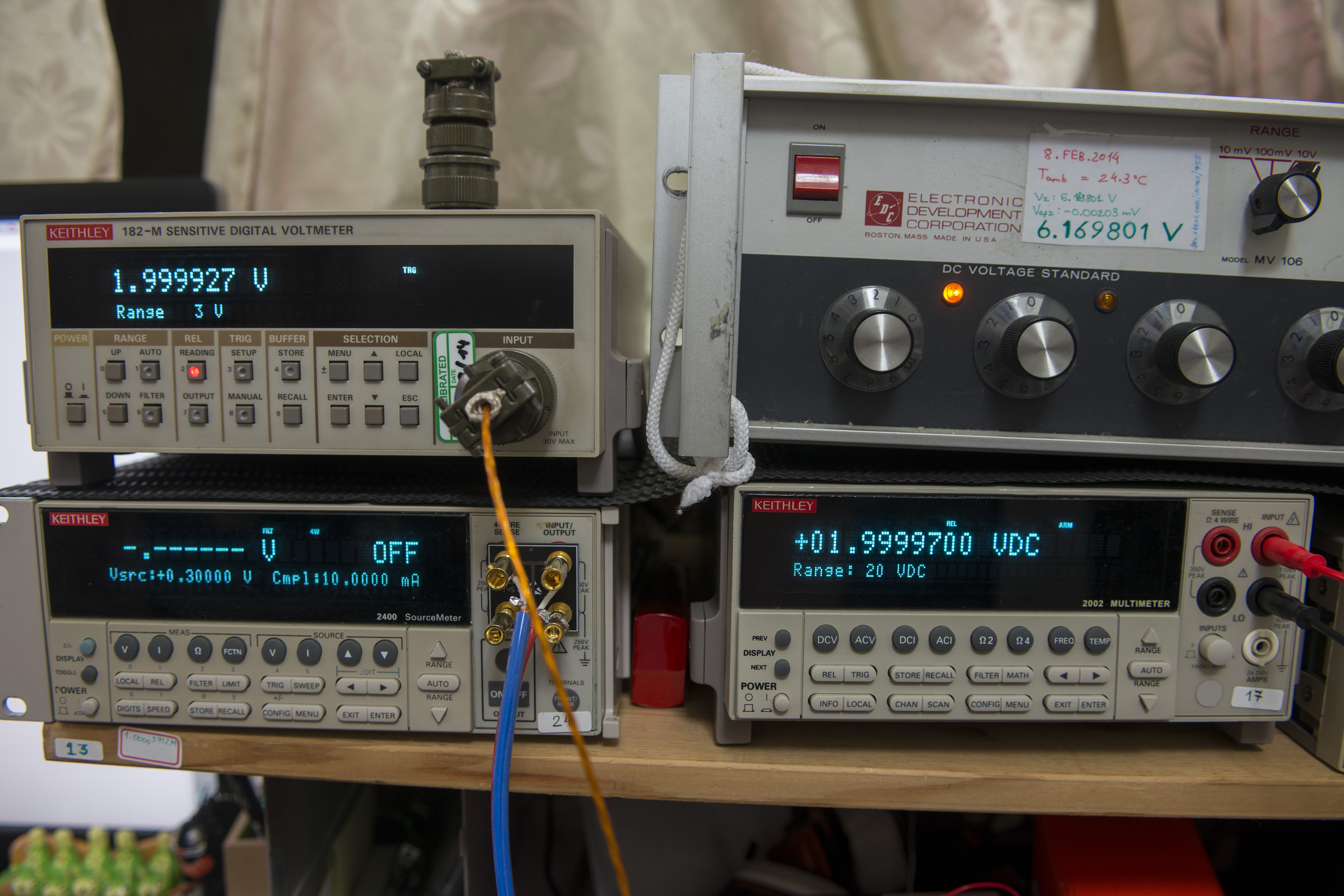
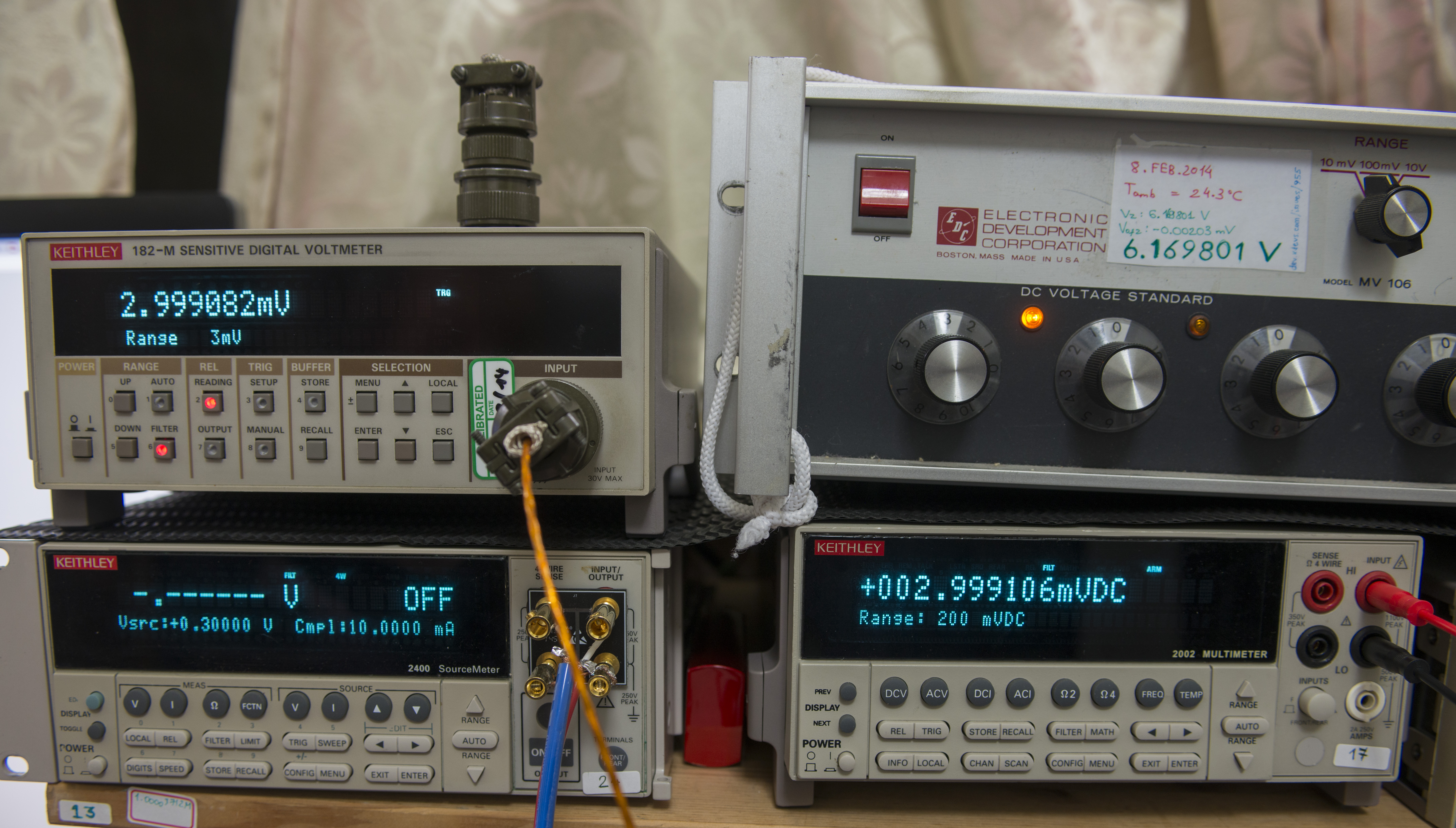
For this task I’ll use EDC MV106 DC Voltage standard, which have 100mV, 1V and 10V ranges, and we compare readings with long-scale DMM.
Overall setup photo:
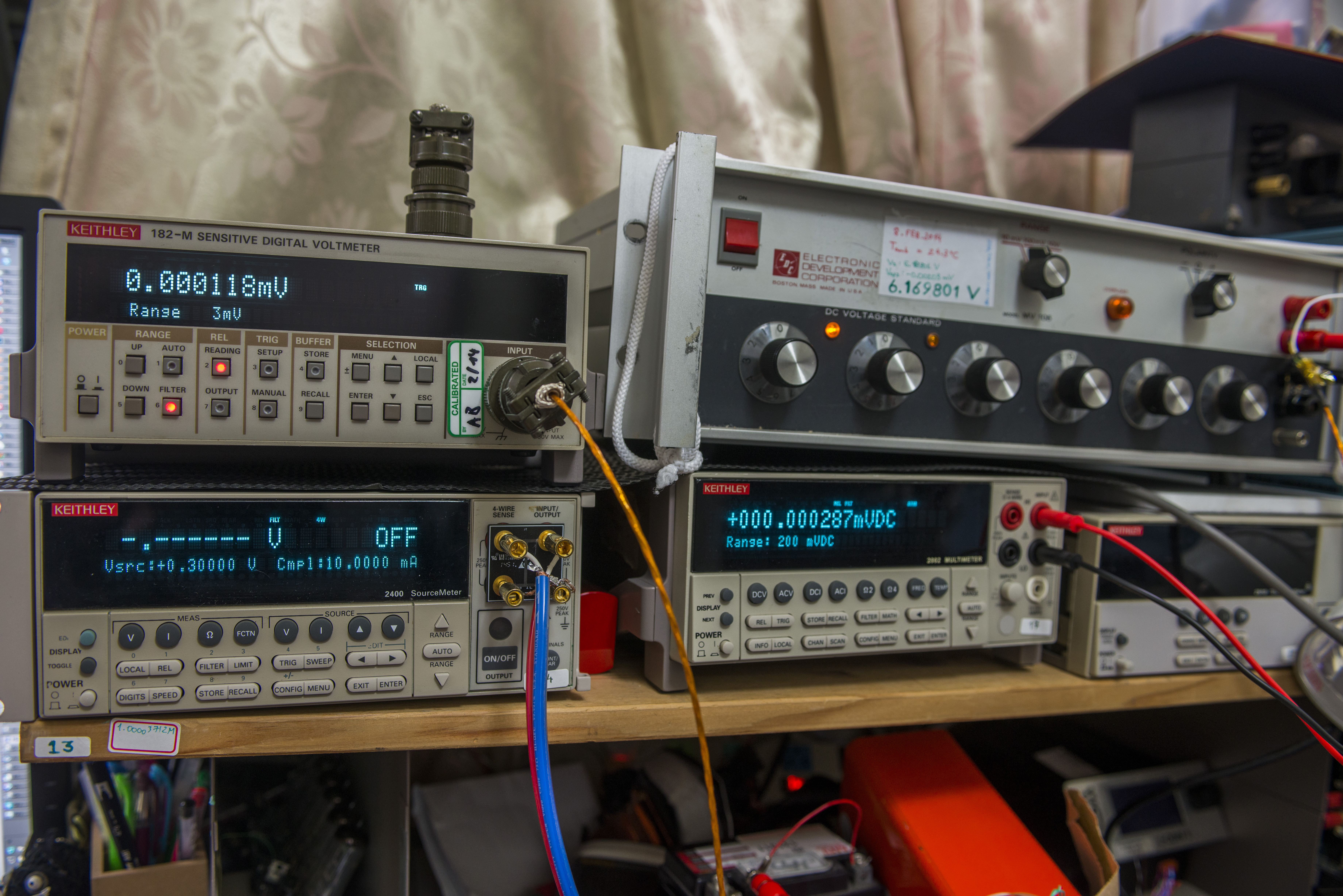
EDC MV106 DC voltage standard box on top right, to supply various VDC levels.
Keithley Model 2002 8½-digit DMM for comparison
Keithley Model 2400 SMU
Test with zero and 3mV from SMU

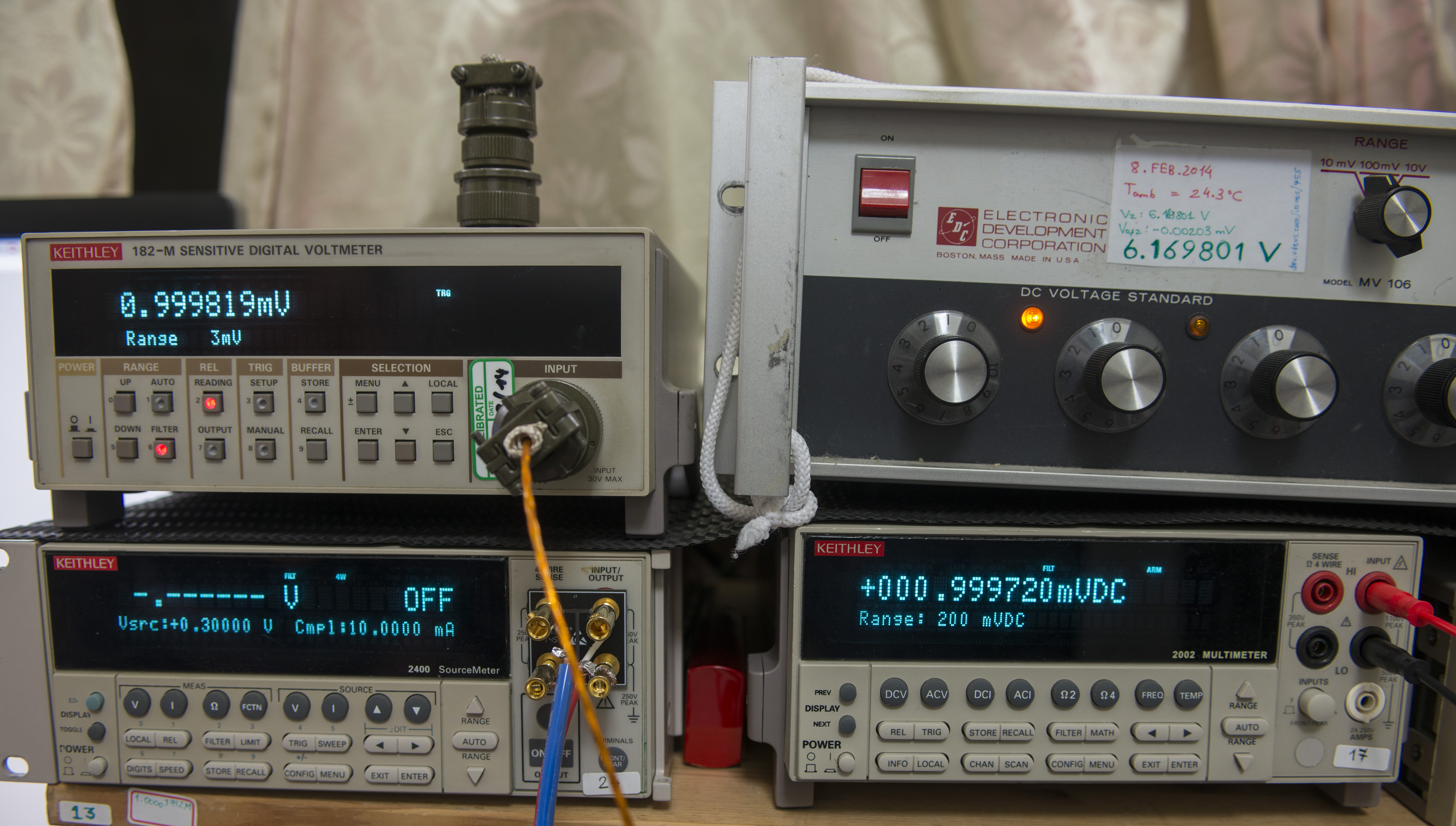
1mV sourced from SMU and EDC MV106:

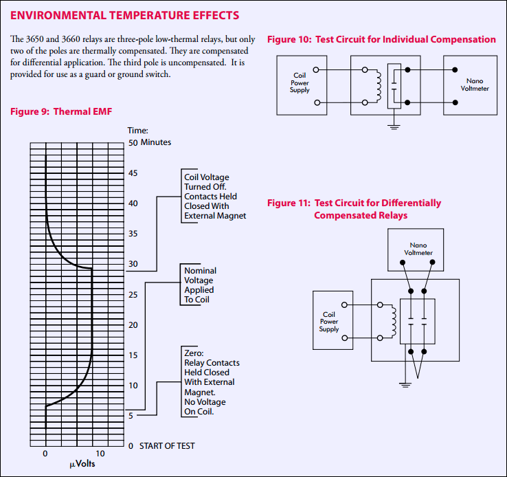
Reed relay thermal EMF test
Input port and connections
As most of nanovoltmeters, this meter using special type connector, Amphenol Industrial 97 series 97-3102A-16-11 (4-129). Mating male cable connetor is available on Digikey for no less than $40 USD.
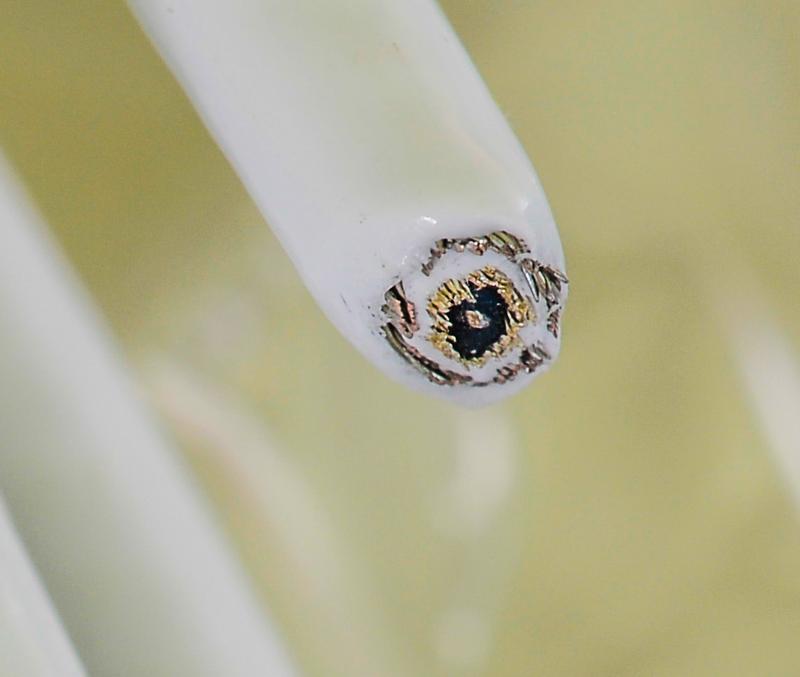
In task of measuring microvolts it’s very important to make proper connection to DUT. The most common sources of error in low voltage measurements are thermoelectric voltages (thermoelectric EMFs) generated by temperature differences between junctions of different metal conductors. This includes PCB traces (copper-tin), wiring, connectors, and test component leads. There is good example of thermal EMF impact shown in this Fluke application note from Martin L. Kidd
I made custom triax cable using medical grade CNMC low-noise triax wire.
Test with DC voltage standard
2VDC and 3mVDC from MV106
Test in progress..
Metal bar resistance measurement
For this experiment few pieces of copper bars will be measured, as well as standard current shunts.
Two instruments will be used for this experiment:
Keithley 2400 SMU as current source
Keithley 182-M to read voltage
Also conventional long-scale DMM Keithley 2002 in 4W-ohm mode will be used for comparison.
Test in progress..
Noise measurement with short
Test in progress…
Noise measurement of +12V lead battery
Since we want measure noise only, battery is AC decoupled using bank of polypropylene capacitors. Voltmeter HI input is tied to ground via 10K resistor to provide return current path.
Test in progress…
Noise measurement of LTZ1000A-based voltage reference
Input AC coupling setup is same as with battery.
Test in progress..
Analog output function test
One of special features of Keithley nanovoltmeters is gain-adjustable analog output.
Model 182’s analog output voltage is generated by 14-bit DAC from digital code, supplied from main processor.
Gain and relative function for this output value can be adjusted from front-panel or remotely, allowing to fit wide usage scenarios.
With gain = 1.000000, full-range will provide 3VDC output signal. This means if meter using 30mV range, 30mV signal will result having 3VDC on analog output port. If gain results in higher voltage, maximum output voltage would be ±3.3VDC.
Gain range : 0.001 to 999999.999 with 0.001 resolution.
Maximum output current is 5mA, so loading source should be no less than 1kΩ. Output voltage is in range 0 to ±3VDC.
Test TBD..
Conclusion
This specialty instrument is not an everyday use tool, but for low-level measurement tasks it can do what conventional long-scale DMM can’t.
If you have any comments or experiments to see with this kind of gear, please let us know in comments.
Projects like this are born from passion and a desire to share how things work. Education is the foundation of a healthy society - especially important in today's volatile world. xDevs began as a personal project notepad in Kherson, Ukraine back in 2008 and has grown with support of passionate readers just like you. There are no (and never will be) any ads, sponsors or shareholders behind xDevs.com, just a commitment to inspire and help learning. If you are in a position to help others like us, please consider supporting xDevs.com’s home-country Ukraine in its defense of freedom to speak, freedom to live in peace and freedom to choose their way. You can use official site to support Ukraine – United24 or Help99. Every cent counts.
Modified: June 12, 2016, 5:45 p.m.