- Intro
- Disclaimer
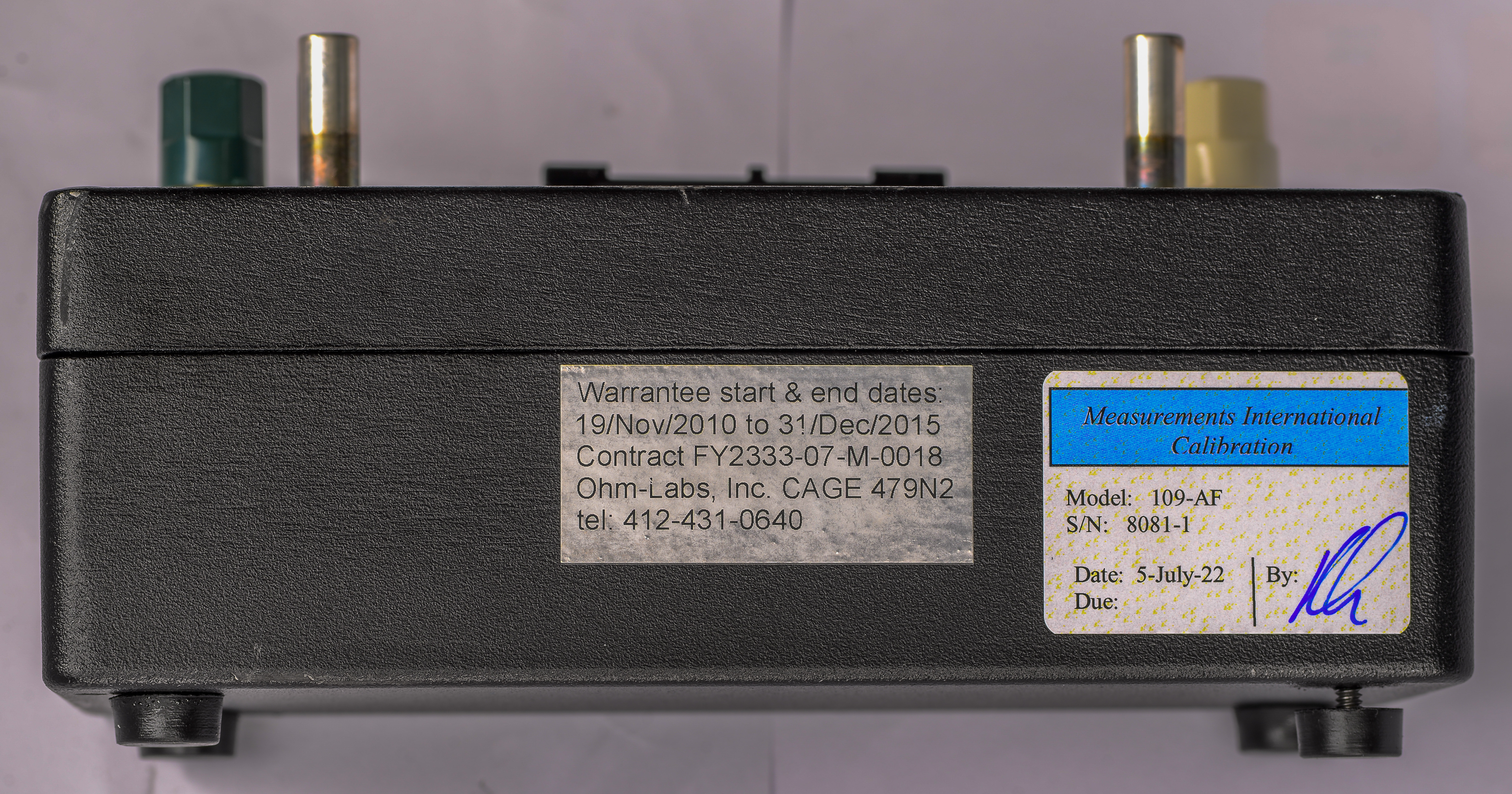
- Ohm-Labs 109 1 GΩ high resistance standard, Model 109
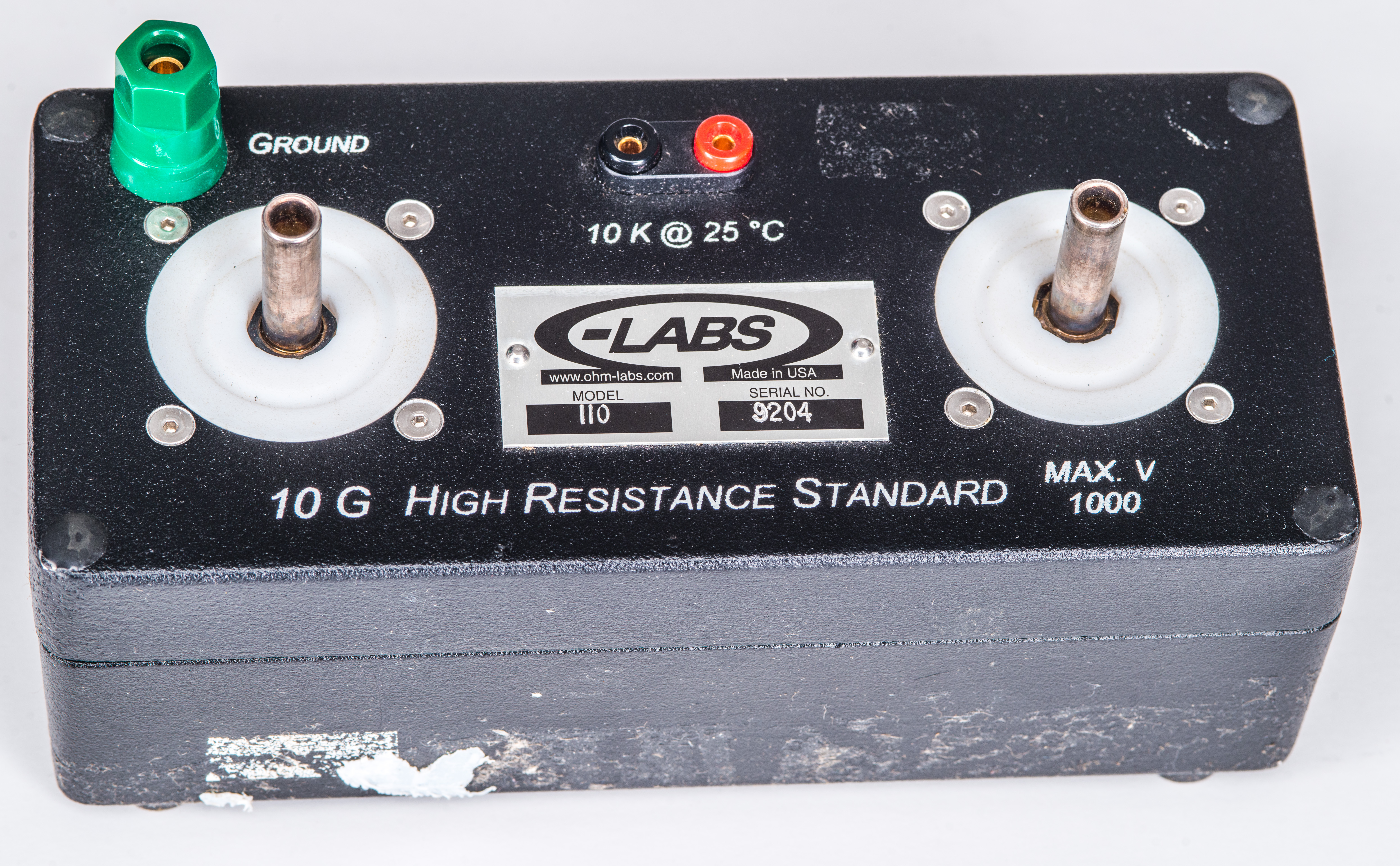
- Ohm-Labs 110 10 GΩ high resistance standard, Model 110
- Benchmarks
- Conclusion and summary
![]()
![]()
![]()
![]()
![]()
![]()
![]()
![]()
![]()
![]()
![]()
![]()
Introduction to Ohm-Labs High resistance standards
Ohm-Labs Inc. is manufacturing high resistance standards 100-series for various metrology applications. In this article we will look and test few of them.
| Unit | S/N | Results | Last known value | Calibration Date, method |
|---|---|---|---|---|
| 109 | 8081-1 | Details 1 | 1.0 GΩ ±20 ppm | MI calibration, 5.JUL.2022 |
| 110 | 9204 | Details 1 | 9.99984 GΩ ±20 ppm 200 V | Factory calibration, 24.DEC.2009 |
Disclaimer
Redistribution and use of this article, any part of it or any images or files referenced in it, in source and binary forms, with or without modification, are permitted provided that the following conditions are met:
- Redistributions of article must retain the above copyright notice, this list of conditions, link to this page (https://xdevs.com/review/ohmlabs_hires/) and the following disclaimer.
- Redistributions of files in binary form must reproduce the above copyright notice, this list of conditions, link to this page (https://xdevs.com/review/ohmlabs_hires/), and the following disclaimer in the documentation and/or other materials provided with the distribution, for example Readme file.
All information posted here is hosted just for education purposes and provided AS IS. In no event shall the author, xDevs.com site, or any other 3rd party be liable for any special, direct, indirect, or consequential damages or any damages whatsoever resulting from loss of use, data or profits, whether in an action of contract, negligence or other tortuous action, arising out of or in connection with the use or performance of information published here.
If you willing to contribute or add your experience regarding instrument repairs or provide extra information, you can do so following these simple instructions.
Ohm-Labs 109 1 GΩ high resistance standard, Model 109
Specification for this resistance standard from Ohm-Labs website:
- Initial absolute tolerance within 35 ppm
- Temperature coefficient better than 30 ppm/K
- Voltage coefficient better than 0.1 ppm/V
- Stability 6 month 15 ppm
- Stability 1 year 25 ppm
- Recommended 100 V test voltage
Ohm-Labs 100 series Guarded High Resistance Standards, Datasheet
Ohm-Labs 100 series Guarded High Resistance Standards, Instruction manual
NA 1 GΩ interlaboratory comparison report from 2006-2008
This 1 GΩ standard is equipped with special BPO silver-plated connectors. There is somewhat strange specification regarding maximum acceptable voltage for these standards. Ohm-Labs website and short datasheet outlines max voltage at 10 kV for models 109 and 110 (1 GΩ and 10 GΩ) but manual document has additional column in spec table with maximum voltage at only 1 kV.
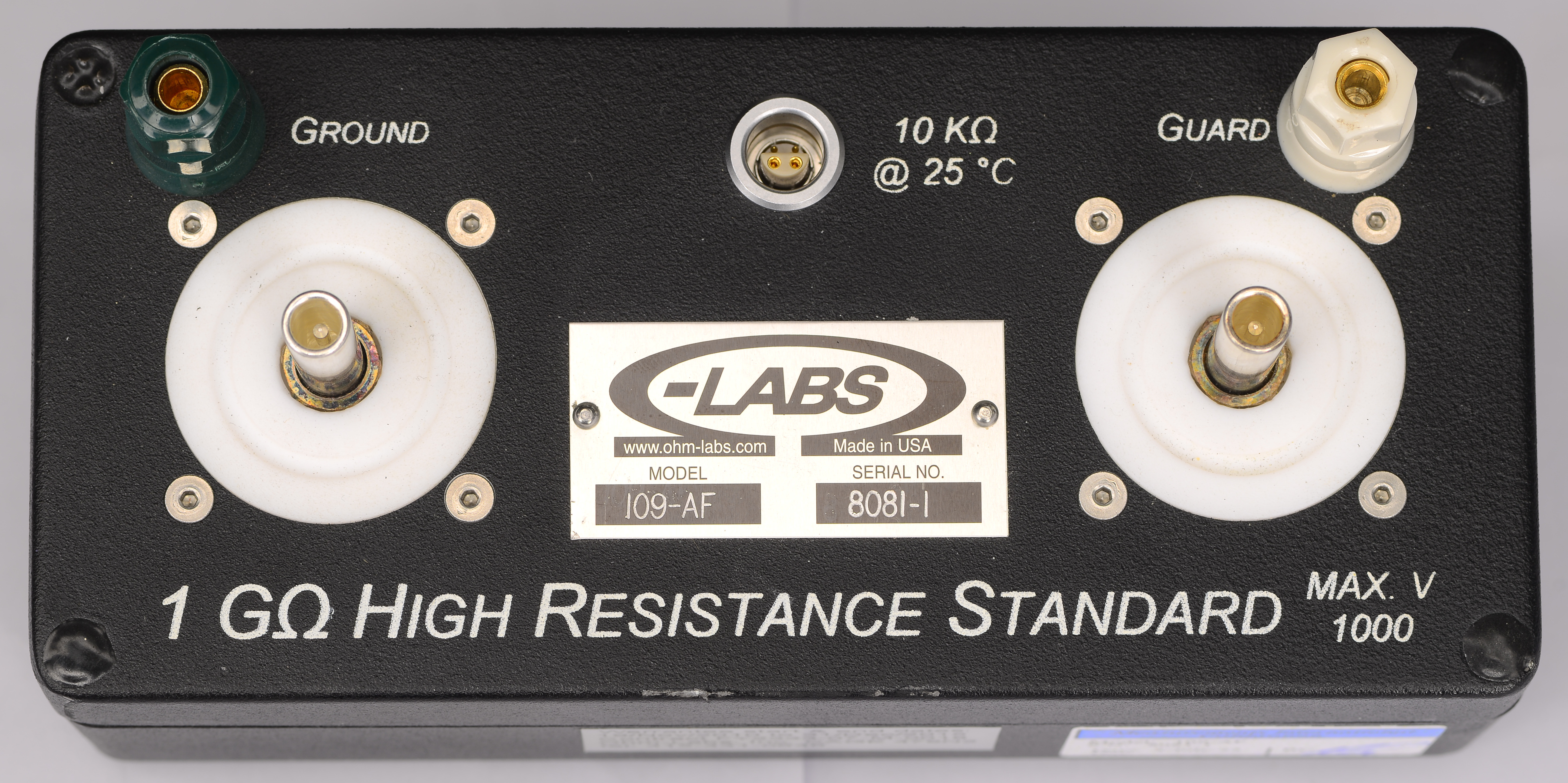
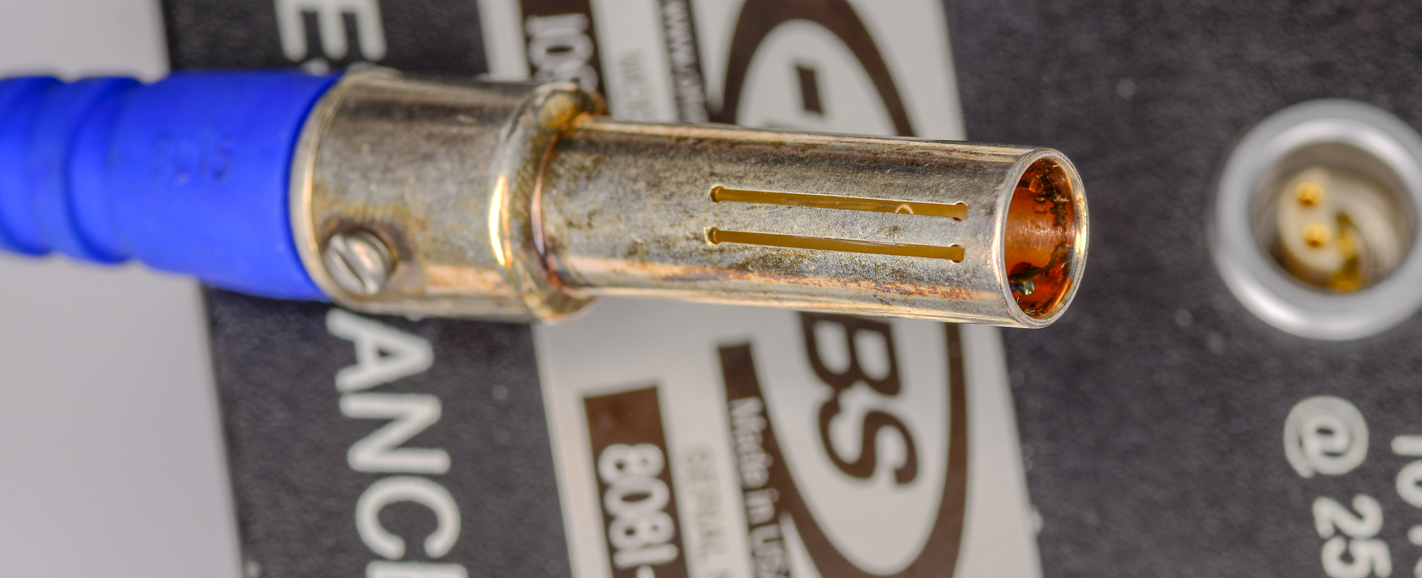
Unlike more popular resistance standards such as Fluke 742A this unit has BPO or MUSA connector. BPO connector is male coaxial, often with 75 Ω impedance type, has panel mounting with solder connection pin and metal tag connected to outer tube. The body parts are silver plated brass and center contact is silver plated beryllium copper.
Opposite to BNC or N-type this BPO connector has no locking mechanism to allow quick and reliable connection without additional mechanical operations. Long outer body helps to ensure good alignment of center contact during use.
BPO connectors are installed on large white pads made out of PTFE also known as Teflon™. Pads provide very high insulation resistance to chassis and isolate chassis body from any potential since outer shells of BPO connectors are usually actively guarded to reduce leakage effects.
BPO connectors are widely used in high resistance and AC/DC impedance metrology applications, especially at NMI lab level. One can find many examples of these connectors with quadrature and capacitance bridges as well.
Canford in UK is one of the manufacturers of these connectors today.
Since temperature stability of high value resistive elements is worse to resistance elements in kΩ range Ohm-Labs put handy thermistor probe inside of the resistor body. Connection to thermistor is provided with LEMO 2B 4-contact terminal. Thermistor sensor has nominal resistance 10000 Ω at reference temperature +25°C.
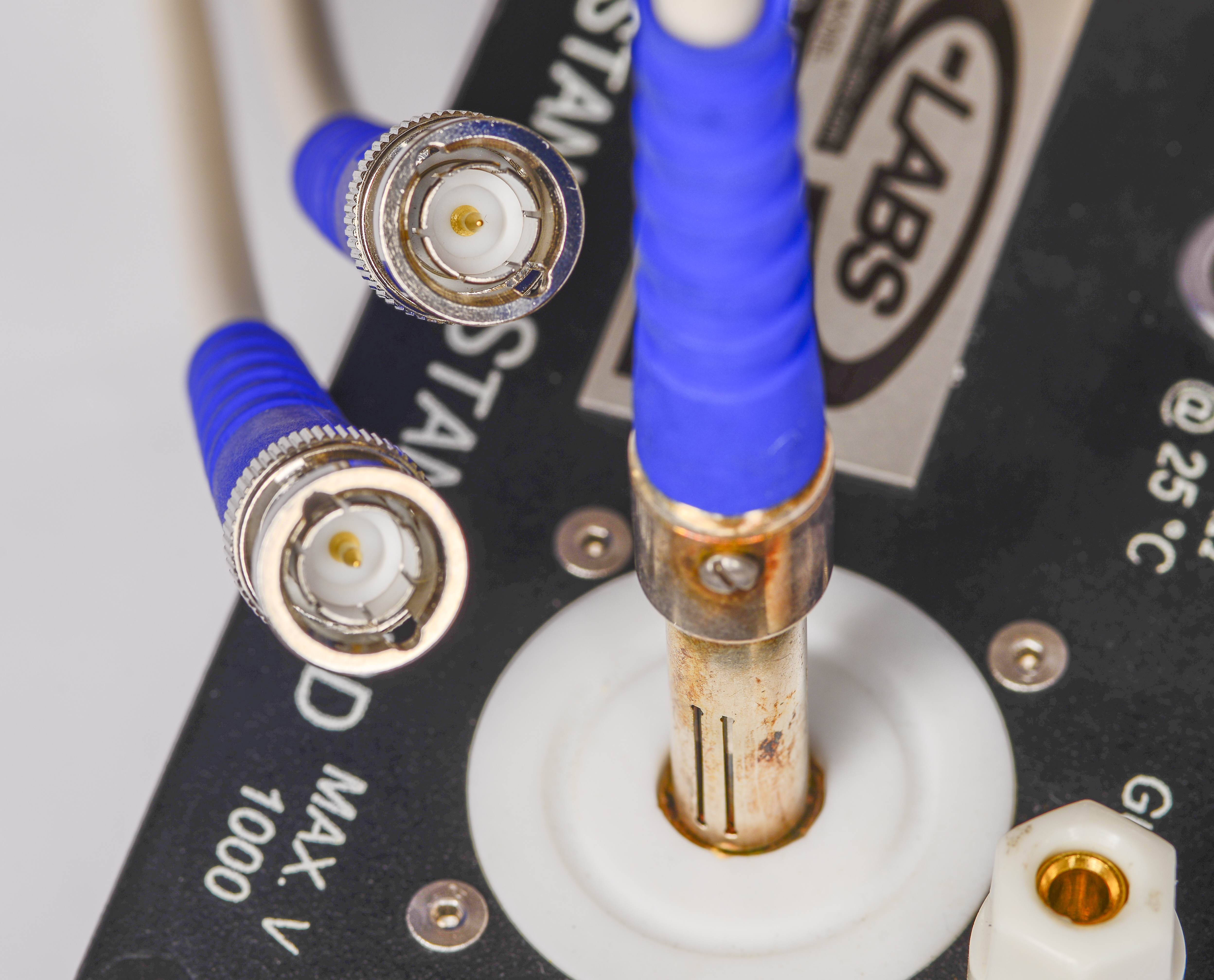
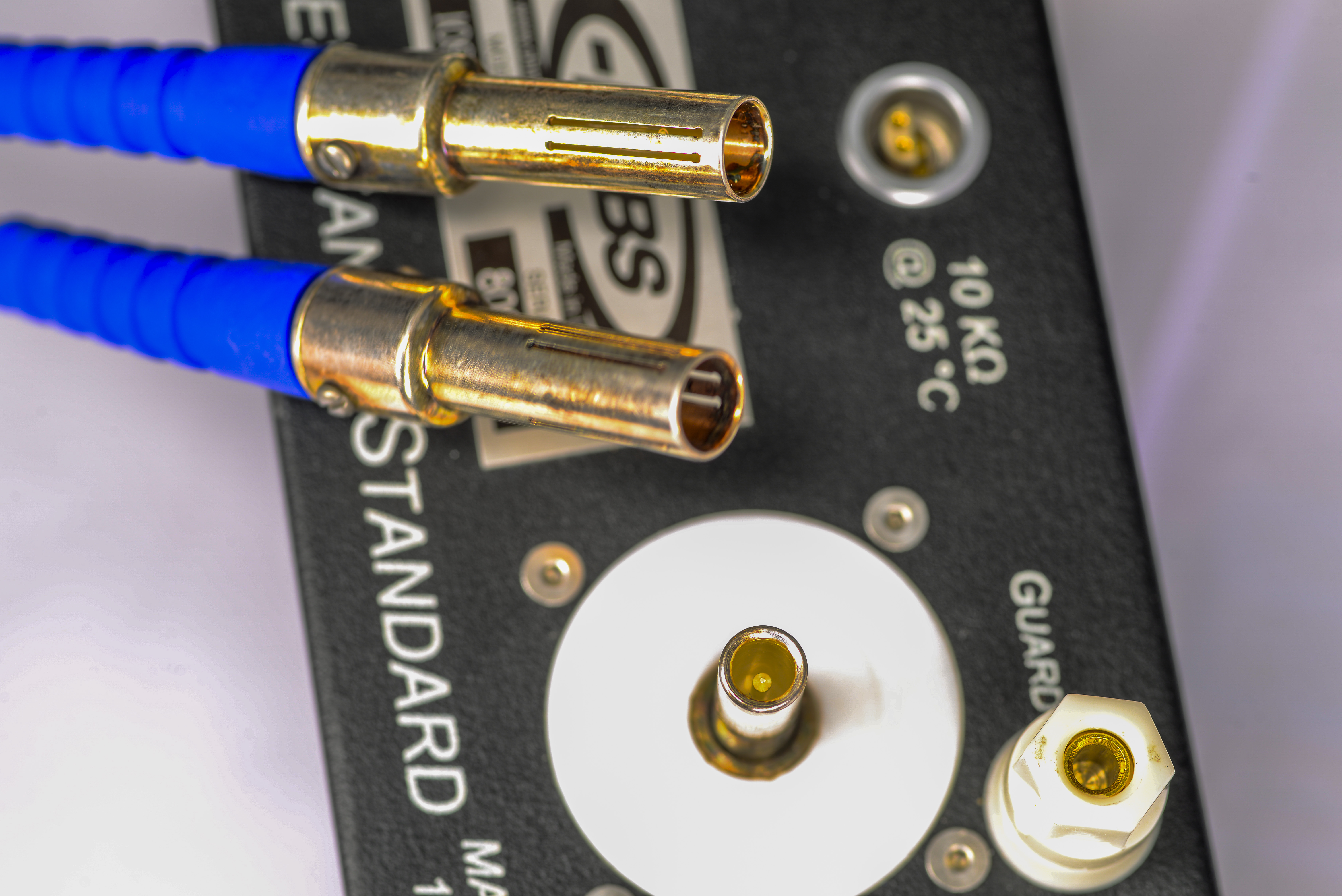
This standard was used with custom Ohm-Labs made 75 Ω cables with BPO receptacles on DUT side and 75 Ω BNC male connectors on the host side. These cables have Ohm-Labs part number EL4305. Each cable have length 1 meter and was around $50 USD/each back in year 2016.
Ohm-Labs also sells accessory and adapters, such as BPO to BNC male (Ohm-Labs P/N EL4302 for BNC male and EL4303 for female BNC version) were about $35 USD/each back in 2016.
- Silver plated / solid silver pin male BPO panel connectors, similar to those on the standards product.
- Silver plated BPO female cable connectors
- BPO to BPO cable, 1 meter
- BPO to BNC cable, 1 meter
- BPO to BNC adapters
- Low noise BPO to gold plated solid copper low-thermal spade fork terminal cable, 1 meter (Red, Blue, Yellow and Black available)

Same cable set was included with standard during external accredited calibration. Cable itself is manufactured by Bryant, model MVC 333C.
This standard has current calibration by Measurements International on July 5th, 2022.
Ohm-Labs 110 10 GΩ high resistance standard, Model 110
Specification for this resistance standard from Ohm-Labs website:
- Initial absolute tolerance within 50 ppm
- Temperature coefficient better than 35 ppm/K
- Voltage coefficient better than 0.1 ppm/V
- Stability 6 month 25 ppm
- Stability 1 year 50 ppm
- Recommended 100 V test voltage
- Maximum voltage 10 kV
Original calibration values for this standards from December 24, 2009 were:
- 9.99982 GΩ with 50 ppm uncertainty at test voltage 100 VDC (-18 ppm from nominal 10 GΩ)
- 9.99984 GΩ with 50 ppm uncertainty at test voltage 200 VDC (-16 ppm from nominal 10 GΩ)
Thermistor readout during these factory measurements were 10911 Ω with 2Ω uncertainty with oven temperature at +22.965 °C ±0.022 °C uncertainty.
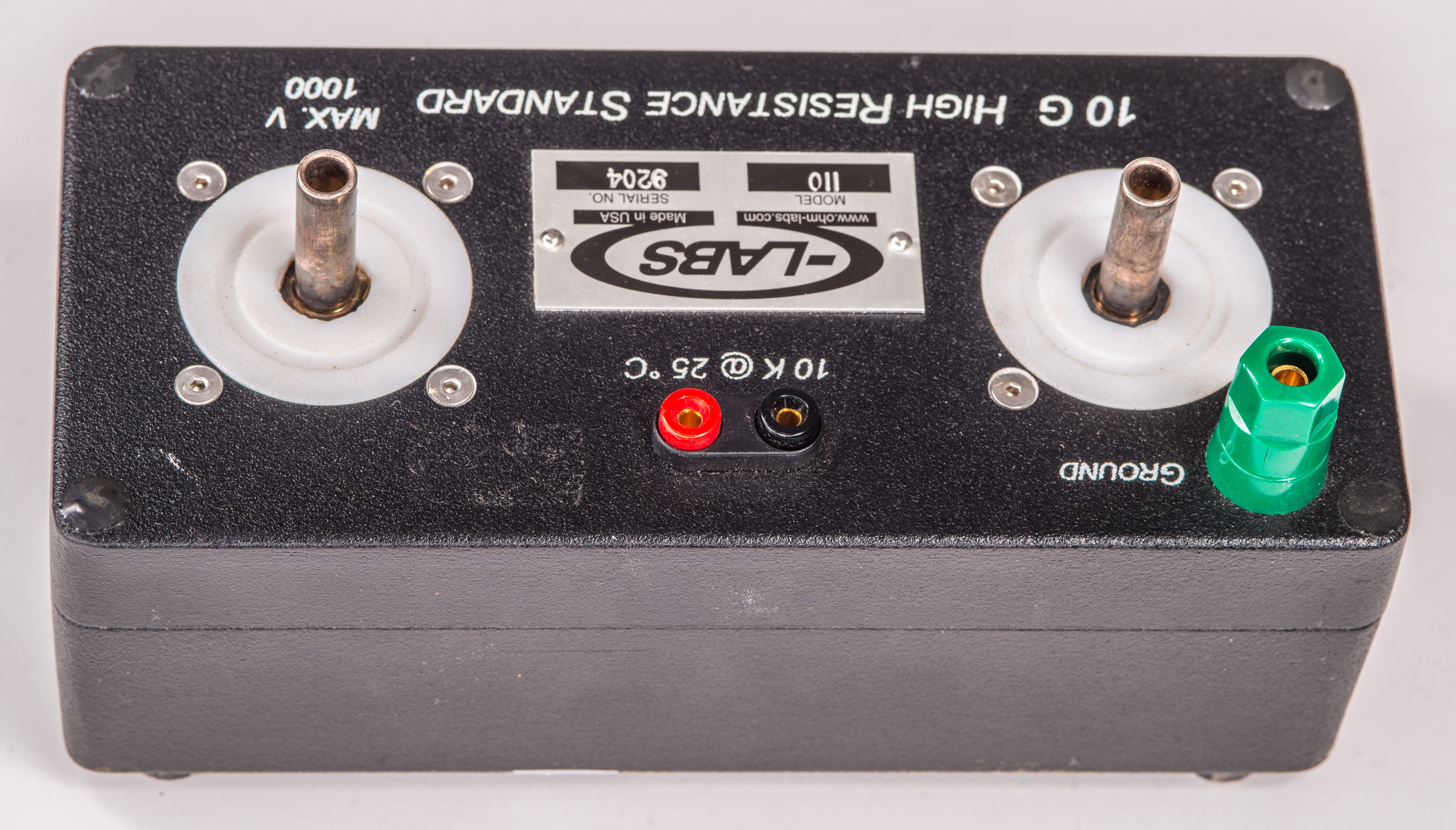
Just like previous 1 GΩ this standard is also equipped with BPO (MUSA) silver-plated connectors.
It was received from secondary market in slightly beat up condition with lot of sticker residue goo on the body.
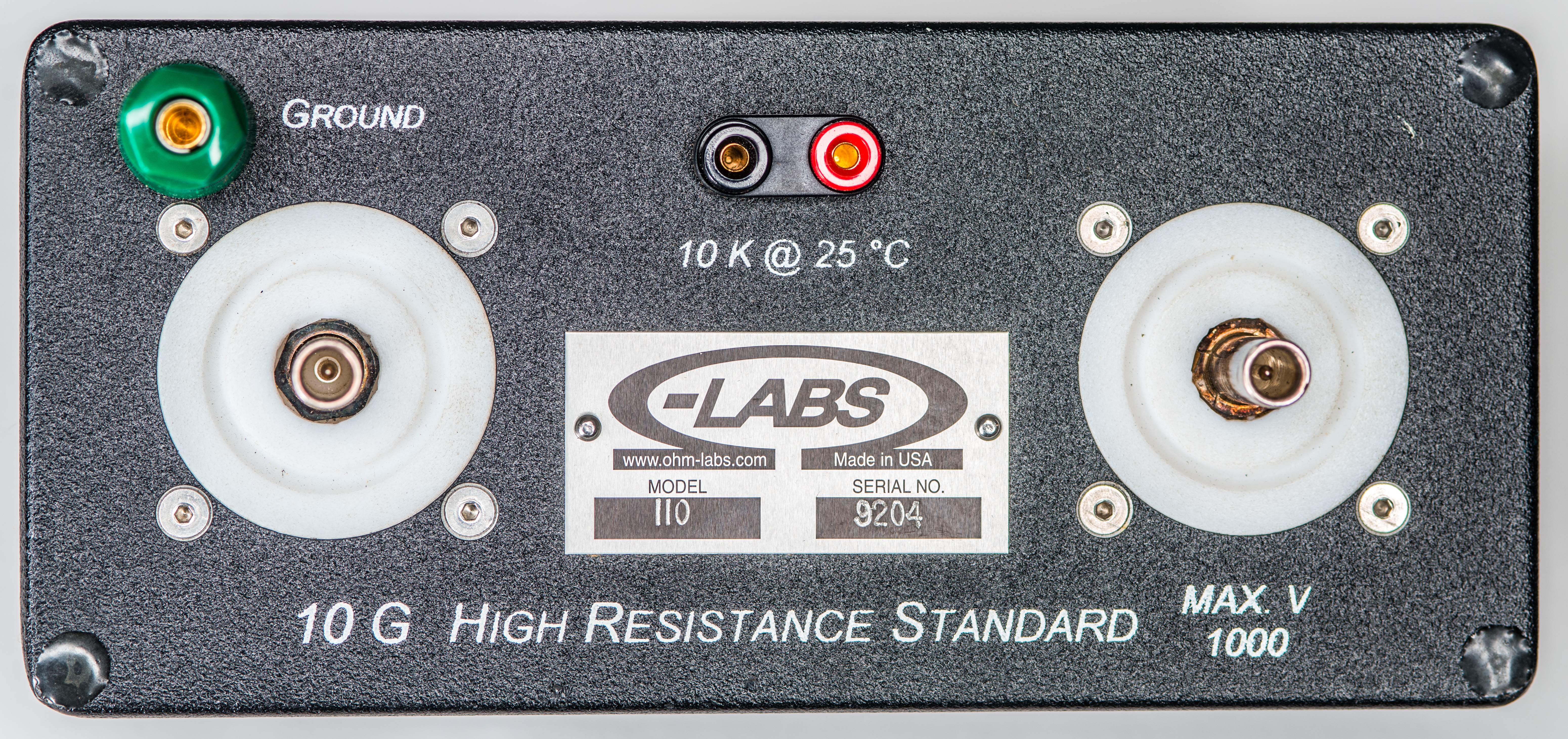
A 10 kΩ nominal at 25 °C thermistor is integrated in resistor body, enabling monitoring the internal temperature for additional corrections/uncertainty analysis. 2-wire connection is provided by compact 2 mm pitch mini-banana plugs.
Teardown of Ohm-Labs 110 resistance standard
Since there is no much history on this Model 110 standard we decided to go with further analysis of internal design and construction by performing partial diassembly.
Construction of standard is quite typical with thick-walled metal box enclosure. Sadly there are additional complications for field service and possible repairs of these standards. Ohm-Labs used non-standard bolts with custom heads and applied dense potting epoxy to further complicate disassembly.
To perform further tear-down epoxy was mechanically removed which took quite some time. While we agree with idea that users should NOT be taking calibration standards apart without actual reason additional potting and preventing disassembly is not helping.
Also before somebody say that these measures are implemented to protect design IP(Intellectual property), it’s not really true either, since potting or non-standard bolts would not stop anyone dedicated enough to try copy the standard. After all angle grinder and Dremel are still widely accessible tools.
Per note in manual either terminal may be high potential, but it is recommended to match the factory calibration conditions setup. Per Ohm-Labs’ definition left terminal (closest to ground terminal) should be at low potential and the right terminal is at high potential. It is more clear now why such preference, as trim network is better to be placed on high potential side to limit the leakage effects of resistive trim network outside of the hermetically sealed main resistance element can.
Metal can has hand-written labels, stating “10 G, Nichrom, 12.21.09”. Perhaps this means that element was manufactured on December 21, 2009.
Glass sealed insulator has some flux residue left over by assembly process. Since resistor standard brass tube is not shield but a guard it may have no significant impact on the performance of the unit. Either way flux was cleaned with 99% IPA before reassembly.
Guard resistors most likely are Ohmite P/N SM204035007PE with market price around $3 USD/each. They are 5 GΩ Ohmite Slim-Mox 204E resistors. Date code 0940 also confirms the same time frame of this Model 110 standard manufacture close to December 2009. Slim-Mox 204E type is rated for 2W power dissipation and maximum voltage up to 10 kV, so perhaps that is where datasheet maximum voltage comes from?
Middle point between two of these resistors is connected to main standard element metal body now which has active guard potential. Other resistor wire from this network connected goes to outer contacts of the BPO terminals. With external guard potential connected to outer shields such arrangement forms a resistive voltage divider network. Active guarding helps to reduce leakage and capacitive loading to the sensitive nodes.
NTC is a tiny bead with thin twisted pair wire of sizeable length running to mini-banana connector. Sensor itself was shoved behind foam on the top cover of the metal box enclosure, right behind the thermistor connector. So it is not running anywhere near the actual resistive standard element or guard network.
As a result thermistor sensor is more of relative indication of temperature inside of the box, and not a direct temperature of resistive element. This may be visible in future testing by comparing thermal delay results with thermistor readout.
Resistors look like typical 5% and 1% thru-hole parts cheaply available on Digikey or similar retail stores. Connections between resistors and BPO center pin are protected by black thermalshrink tubing but some areas are left exposed. Gold-plated wire that goes to main element metal body has additional clear plastic (could be PTFE) insulator, which is somewhat important as there is not a lot of clearance to metal can body left.
Based on this teardown we can determine actual design schematics of this standard.
This standard isn’t very practical for my lab use with BPO connectors. I’ve decided to modify it a little bit by replacing BPO connectors with more traditional triaxial ports. This way I can use it with same cabling and interconnects as other high-resistance standards and devices I got in the lab.
I had to remove BPO connectors with bit of gentle hammer action as they were press-fit into PTFE donuts. Then drilled stepped hole with 11 and 12.5 mm drills and press-fit triaxial 3-lug female connectors into openings. Overall easy 10 minute job.
Finished standard after reassembly:
Benchmarks
| Model and serial | Calibration date | Assigned value | Uncertainty | Calculated drift | Points in calculation |
|---|---|---|---|---|---|
| Ohm-Labs Inc. 109, S/N 8081-1 | 5.JUL.2022 by MI | 1.000037 GΩ 100 V | ± 9 ppm | ||
| Ohm-Labs Inc. 110, S/N 9204 | 24.DEC.2009 by Ohm-Labs Inc. | 9.99982 GΩ 100 V | ± 50 ppm | ||
| Ohm-Labs Inc. 110, S/N 9204 | 24.DEC.2009 by Ohm-Labs Inc. | 9.99984 GΩ 200 V | ± 50 ppm |
Measurement methods for high resistance
Resistance measurements over 100 MΩ are high enough to provide a challenge for most of handheld and even benchtop DMMs. Long-scale DMM like HP 3458A or Keysight 34465A/34470A support maximum only up to 1 GΩ , Datron 1281 and Keithley 2001/2002 up to 2 GΩ.
More expensive Fluke 8508A supports high voltage mode which extends high resistance ranges to 1.999 GΩ and 19.99 GΩ. Fancy 8588A have similar capability with maximum at 20.2 GΩ with 1 year uncertainty at 1720 ppm of reading + 1290 ppm of range. This is way higher than what Ohm-Labs standard specifications are, so DMMs are not really suitable to measure high resistances over 100 MΩ due to limitations of their universal front-ends, protection circuits and used input connectors.
Resistances over 1 GΩ usually means very low currents in nanoamp region and such levels require guarded and fully shielded signal paths to ensure low leakage and good signal integrity. This often means need of triaxial or guarded coaxial connections, which none of traditional DMMs can offer.
Low current SMU
Some SMUs and parametric analyzers are well equipped to handle very low currents. And because SMU also have integrated voltage source this enables them to measure high resistance quite well.
Electrometer and high-resistance meters
Electrometer is a fancy name of sensitive current or voltage meter with key parameter of very high input impedance. The input resistance for modern electrometers such as Keithley 6517 or Keysight B2980A series is around 100 TΩ compared to over 10 GΩ for high-end traditional DMM. Electrometers have specially designed inputs. This is achieved by using clever design tricks, such as actively guarded shields, PTFE insulation pads and PCB materials, very low bias current opamps and JFET stages with special cables to avoid unwanted leakage currents. Most of electrometers use triaxial connectors to provide low leakage interface to devices under test and probes.
Substitution method
Dual-source bridge (also known as active arm bridge)
Voltage coefficient verification
Temperature coefficient verification
Time stability
Conclusion and summary
The author would like to express our appreciation to the Ohm-Labs Inc. for information about their services and Measurements International for excellent calibration services on our standards and to Todd M. for providing Ohm-Labs 109 for performance testing, analysis and cross-verification of data.
Discussion is very welcome thru comment section or at our own IRC chat server: irc.xdevs.com (standard port 6667, channel: #xDevs.com). Web-interface for access mirrored on this page. If you have information and performance reports of various resistance standards not mentioned or listed in this article, feel free to provide them and we will add them with next article update. We are looking forward to add another Ohm-Labs units in dataset if they become available.
Projects like this are born from passion and a desire to share how things work. Education is the foundation of a healthy society - especially important in today's volatile world. xDevs began as a personal project notepad in Kherson, Ukraine back in 2008 and has grown with support of passionate readers just like you. There are no (and never will be) any ads, sponsors or shareholders behind xDevs.com, just a commitment to inspire and help learning. If you are in a position to help others like us, please consider supporting xDevs.com’s home-country Ukraine in its defense of freedom to speak, freedom to live in peace and freedom to choose their way. You can use official site to support Ukraine – United24 or Help99. Every cent counts.
Modified: June 5, 2025, 7:02 a.m.