- Intro
- Probe Head
- Probe Cable
- Accessories
- Performance in stock configuration
- Additional experiments
- Conclusions
Intro
The SensePeek SP200 is a 10MΩ || 18 pF oscilloscope probe with a fixed 10:1 attenuation and 80 cm cable, designed to fit on SensePeek’s PCBite flexible probe positioner system. The datasheet specifications state 200 MHz bandwidth and 1.75 ns rise time.
As of 2020-11-07 it is an active product and retails for affordable $58 USD.
The SP200 is a custom form factor and appears to be a fully in-house design, not based on an OEM product.
Probe Head
The SP200 is unique in that it’s designed solely for use on a positioner and makes no attempt to be ergonomically suitable for handheld use. The probe consists of a small PCB with an M4 threaded insert soldered to the back end for mounting to a threaded stud on the PCBite positioner arm.
The positioner took some getting used to working with, but gave good results once the limitations of the form factor were understood. Starting out I expected the arm to be stiff and hold its shape when bent, so I kept having problems where I’d come in at a shallow angle and the weight above the tip would cause the arm to tip over. It seems that best results are obtained with the tip, probe body, and arm roughly in a straight line to prevent any forces outside of this plane. The probe prefers to come in at fairly steep vertical angle, at shallower angles it tends to skid sideways. This can make probing smaller test points under a microscope somewhat challenging, but with some practice I was able to make it work.
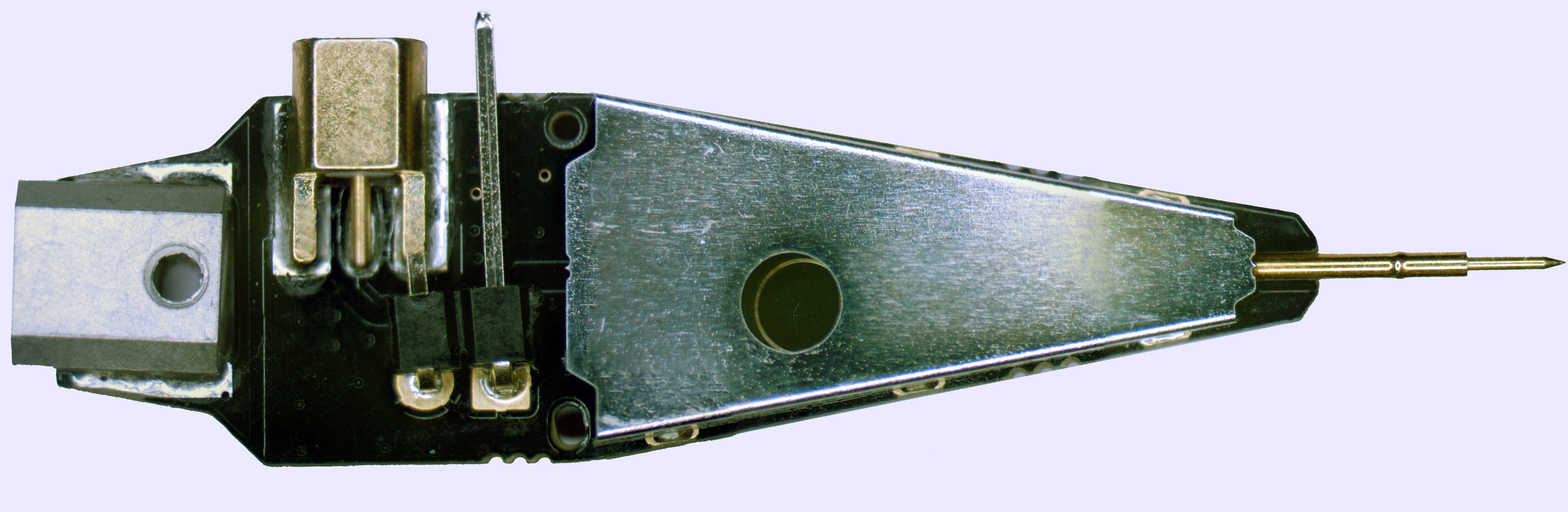
Image 1. SensePeek SP200 probe top side
The probe connects to the DUT via a pogo pin which slides into a cylindrical socket soldered into a slot milled into the PCB. The ground connection is via a single square header pin, which connects via a standard jumper wire to a micro grabber.
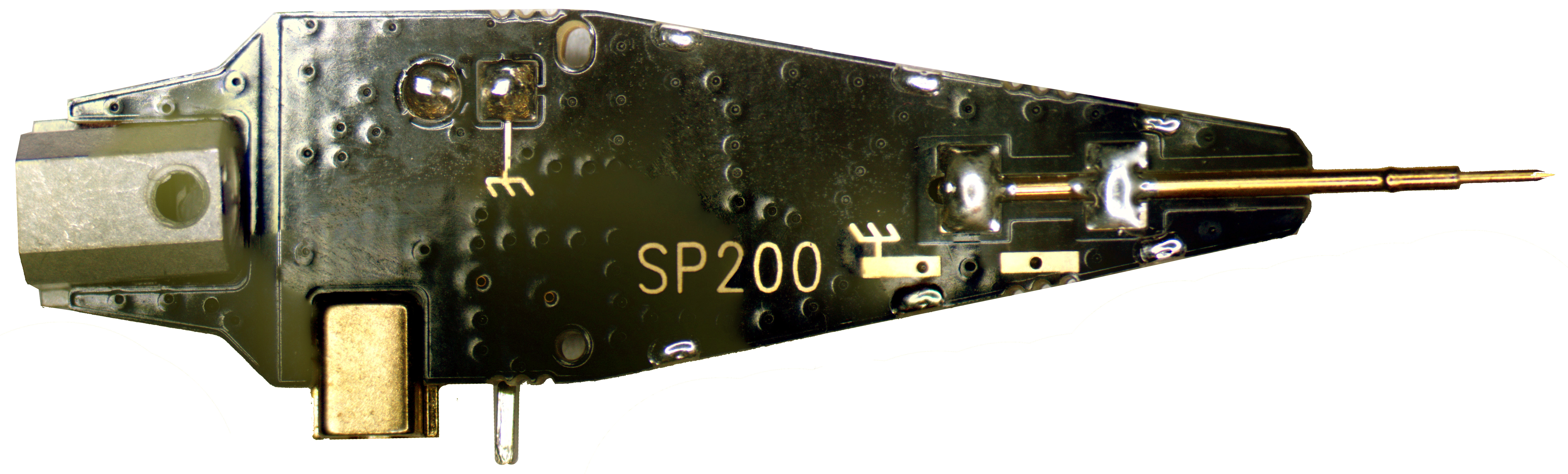
Image 2. SensePeek SP200 probe bottom side
No provision is provided for a low-inductance tip-side ground spring or similar. But there are exposed copper pad designed to allow user easy soldering of ground pogo pin to make proper high-speed measurements with the probe.
An edge launch MMCX connector on the probe head provides a coaxial RF interface to the oscilloscope.
The attenuator on the probe head is hidden behind an EM shield can, so no analysis of the actual circuit could be performed. It is presumably based on the standard R-C divider probe circuit.
Cable
The probe cable has a right angle MMCX at the probe end, and a BNC at the oscilloscope end with compensation components.

Image 3. Cable for the oscilloscope interface
The compensation box is fairly small and has a single adjustment screw for compensation. The exterior of the compensation box is molded ABS and lacks the rubberized grip coating common on higher end probes.
 !
!
Image 4. Compensation ports for calibration adjustment
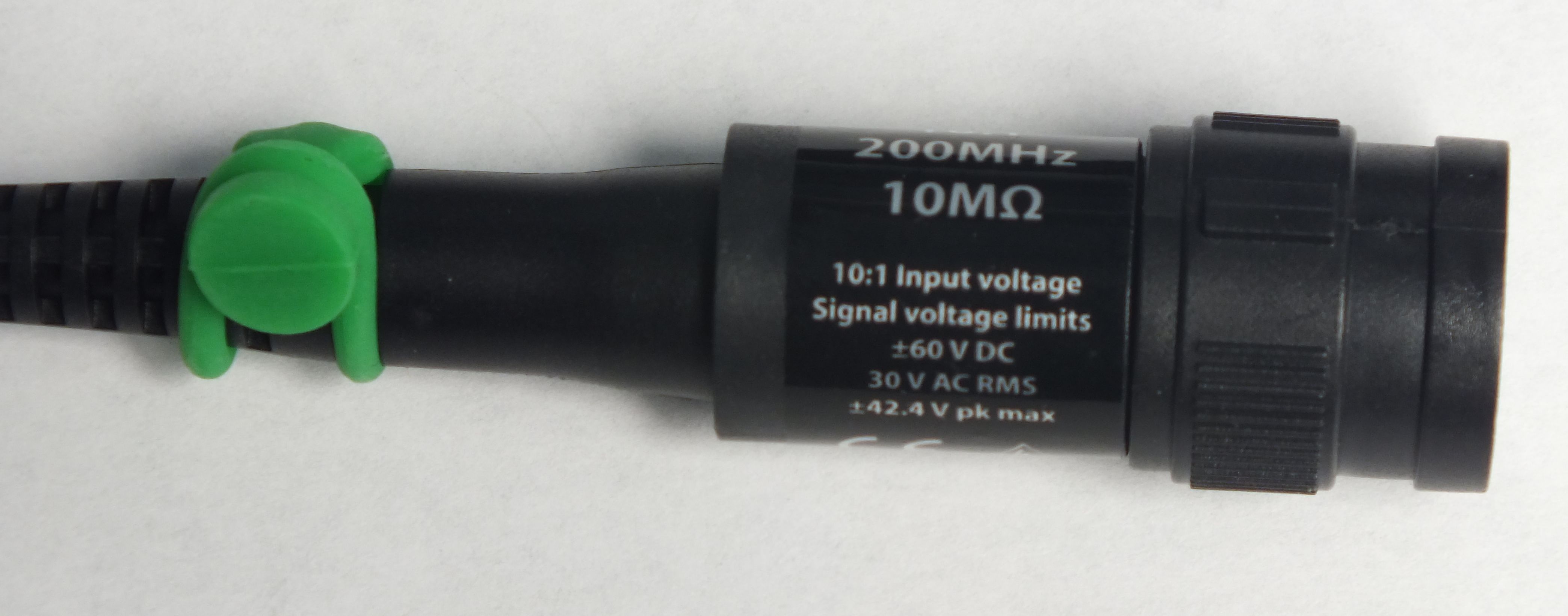
Image 5. Another view on interface
Accessories
The probe comes with a relatively basic accessory kit: a small screwdriver for adjusting compensation, a micro-grabber for grounding, eight color-coded rubber straps for securing the probe cable to the positioner arm, and two different sized wires for connecting the ground lead. No insulating tips for the pogo pin, or alternative grounding accessories, are provided.
Most notably, there is no spring or pin ground suitable for connecting to a test point, adjacent IC pin, decoupling capacitor terminal, or other ground point which cannot be grasped by the micro-grabber. SensePeek’s SP10 probe (a straight-through 1x probe intended for use with multimeters or power supplies) may be used as a ground lead for the SP200 and connected via the same cables used for the micro-grabber at the cost of some additional inductance. The long ~18 inch wire supplied with the SP10 is not recommended for use as a ground lead due to its significant inductance; even at a few MHz massive ringing was present in testing.
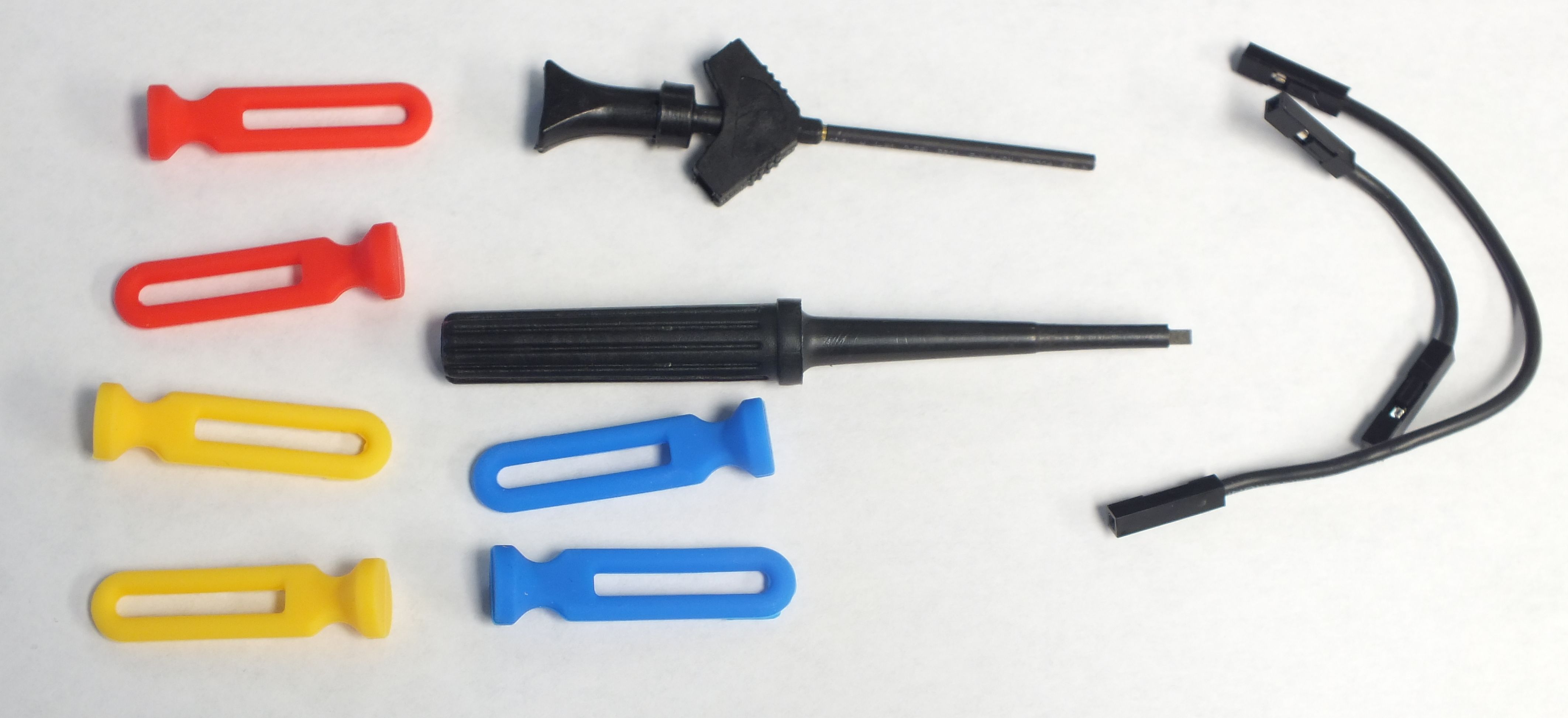
Image 6. Accessories included with the probe set
Performance in stock configuration
Performance testing was conducted on the probe using a Teledyne LeCroy WaveRunner 8404M-MS 4 GHz oscilloscope, a PicoVNA 106 6 GHz VNA, a Leo Bodnar 40ps pulse generator, and a Teledyne LeCroy PCF200 test fixture.
For time domain measurements the pulse generator was connected to the male side of the fixture using a Pomona BNC-SMA adapter and the female side of the fixture was capped with a 50 ohm terminator.
The first test used the micro grabber and the provided long ground wire.
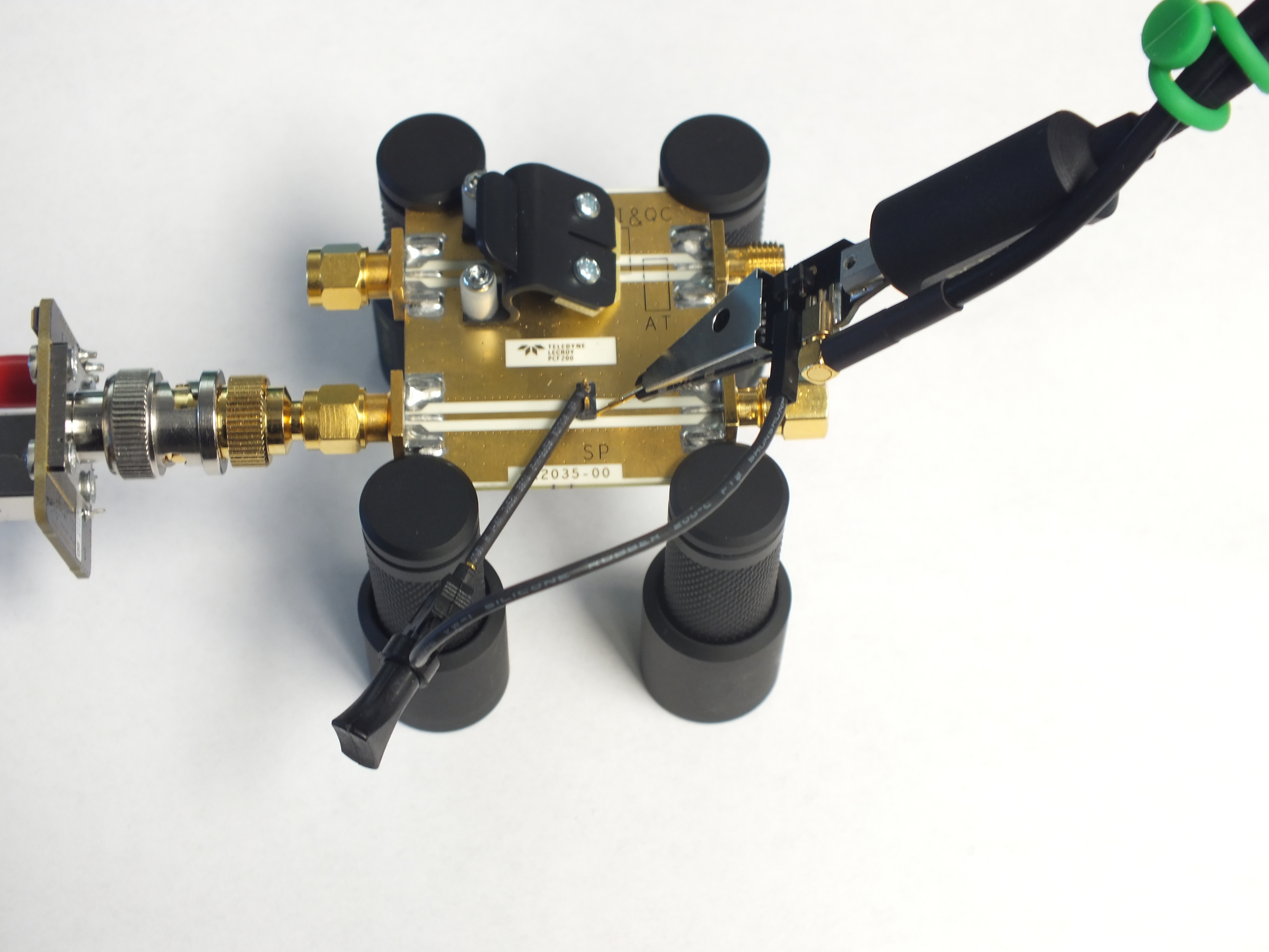
Image 7. Long grounding clip hardware setup

Image 8. Setup overall layout
Unsurprisingly, significant overshoot (25% of p-p) and ringing was observed from the ground inductance of long lead.
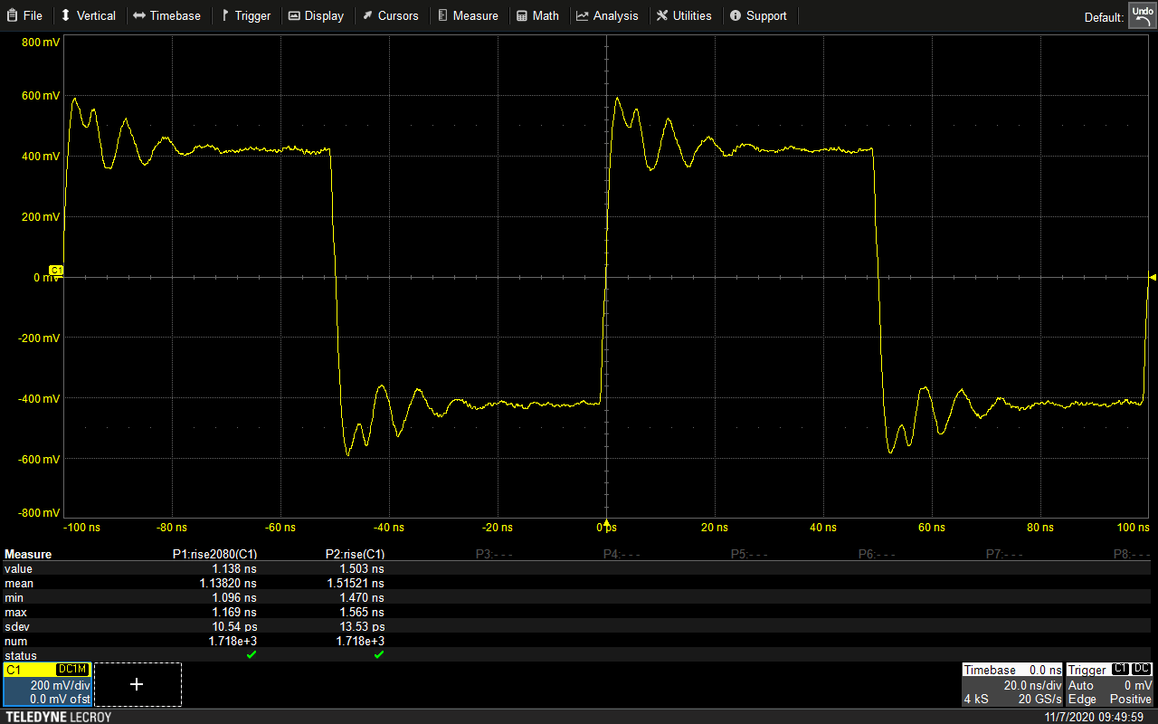
Image 9. Benchmark using fast square wave pulser
Although it was not possible to perform full 2-port VNA measurements because the probe output expects a 1M ohm load rather than a 50 ohm VNA input, scalar S21 measurements were obtained by sweeping tones generated by the VNA across the probe’s operating range and measuring amplitude as seen by the oscilloscope. This curve is normalized to a nominal 0 dB at 10x attenuation, i.e. the amplitude displayed by the scope exactly matches the input signal. Significant artifacts from ground lead inductance are readily apparent in this plot.
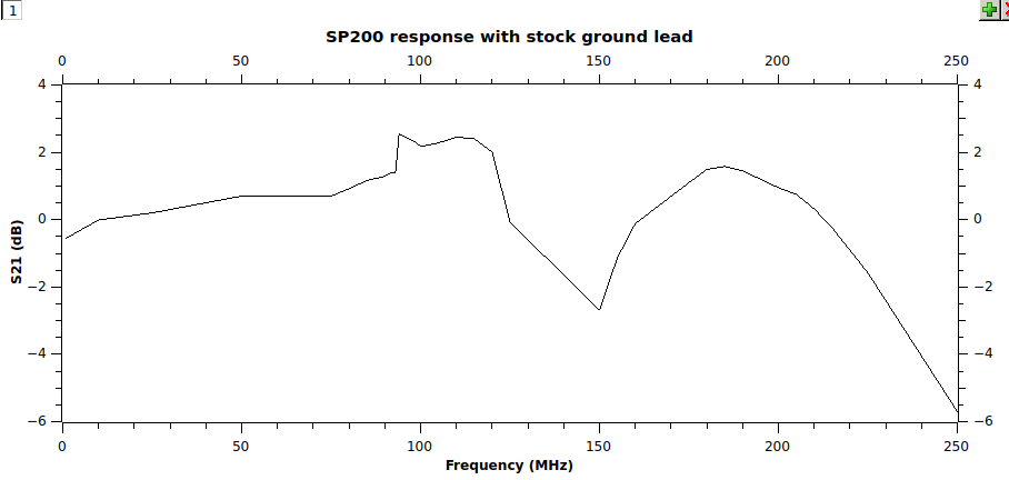
Image 10. S21 network measurements with long ground leg
Input impedance showed the usual sharp drop-off as typically seen with an R-C passive probe, reaching approximately 1K ohms around 10 MHz, 250 ohms at 50 MHz, and 100 ohms at 100 MHz. Multiple huge spikes in impedance were present due to ground lead inductance.
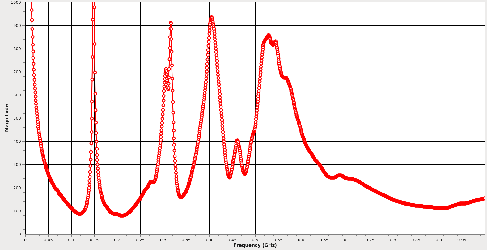
Image 11. Probe input impedance measurement
The second test used the short ground wire. The ringing damped out noticeably faster, but there was less of an improvement than expected.
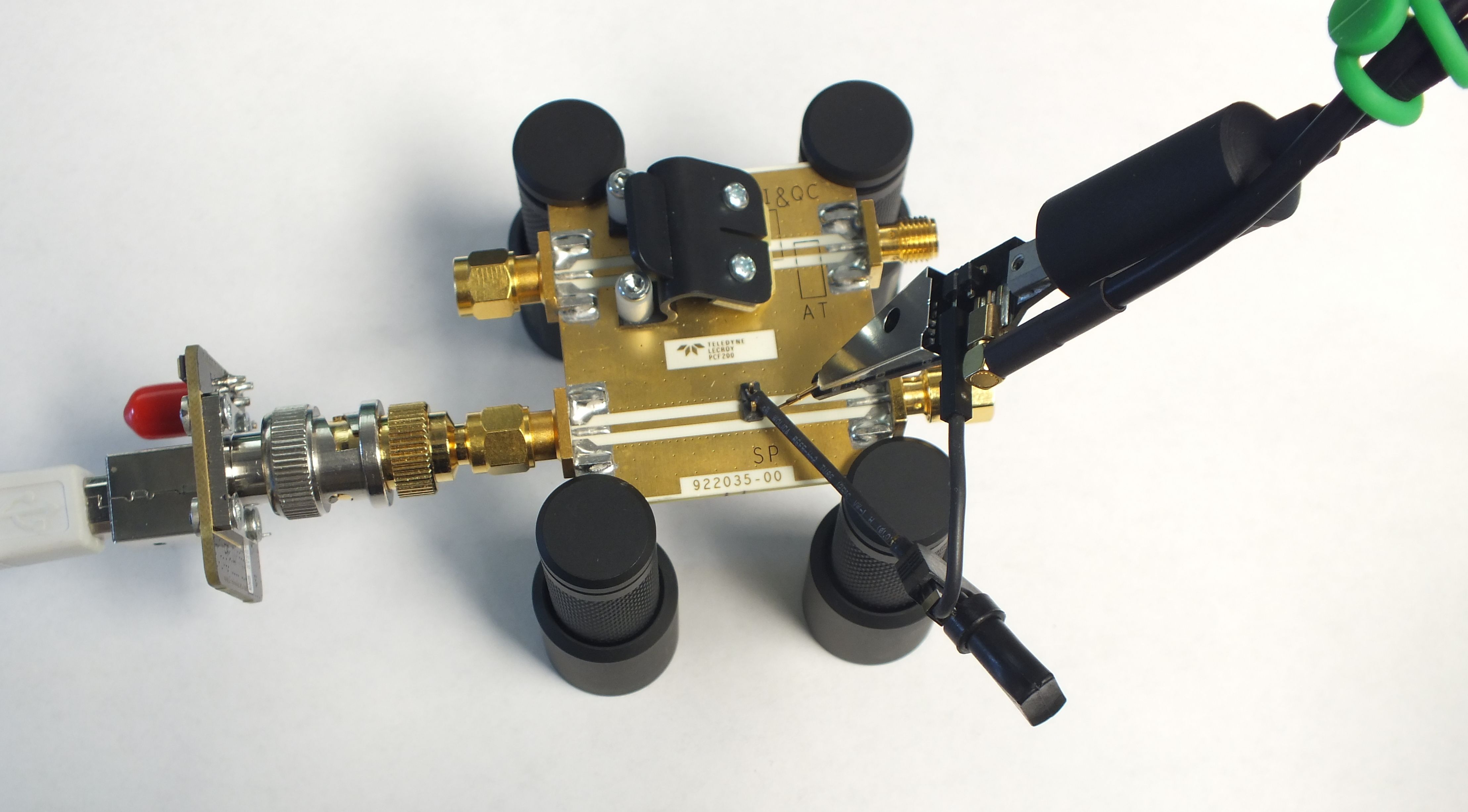
Image 12. Shorter improved ground connection
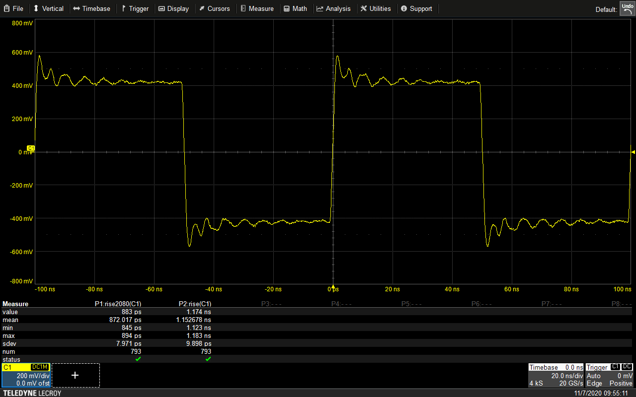
Image 13. Benchmark with fast square wave pulser
It did improve results only a little bit.
Additional experiments
To see if the micro-grabber was the limiting factor in probe performance, a short length of wire was directly clamped to the board as the ground.

Image 14. Connection for ground without grabber use
This can be easily improvised and does not require modification of the probe head, was but again was only slightly better than the stock ground lead.

Image 15. Measurement with fast square wave pulser
The best results as expected were obtained by soldering a short length of 20 AWG solid copper wire to the grounded shield can around the probe tip. With this simple modification, the response flattened out significantly and the -3 dB bandwidth was increased to approximately 375 MHz.
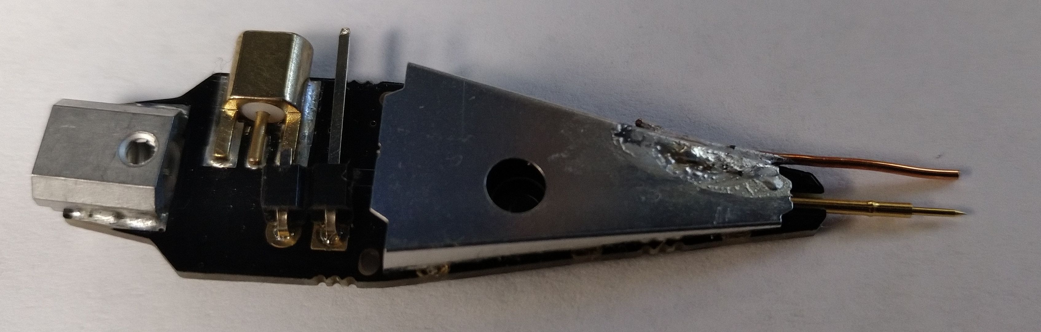
Image 16. Recommended connection method with direct ground interface
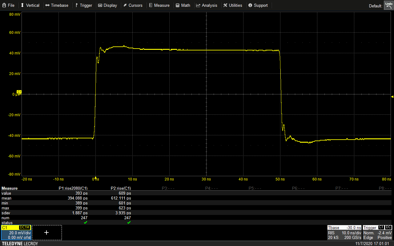
Image 17. Fast square wave signal without much visible ringing
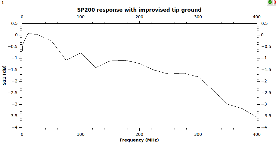
Image 18. S21 measurement results with proper grounding at the probe tip
Input impedance with the tip mounted ground (red) was significantly flatter than the stock ground lead (blue).
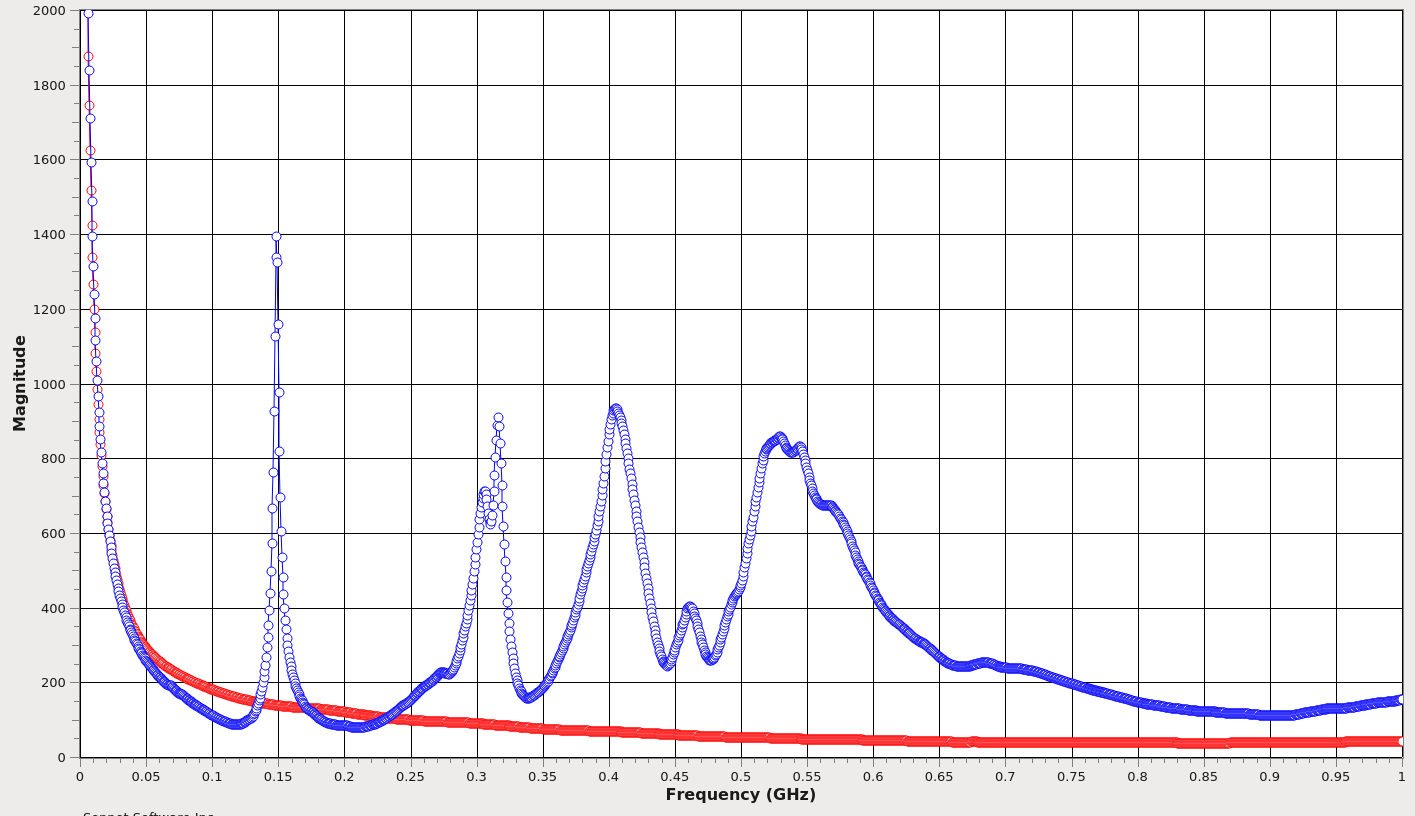
Image 19. Modified probe input impedance measurement from DC to 1 GHz
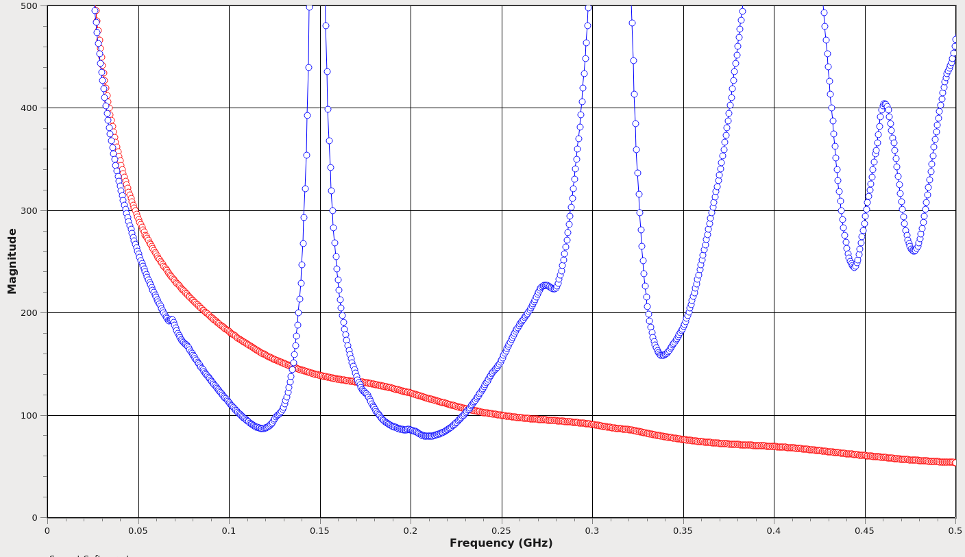
Image 20. Modified probe zoomed in measurement from DC to 500 MHz
Conclusions
The SP200 is a decent value for the money. It definitely can’t compare to high-end passive probes from vendors like Tek, Keysight, or Teledyne LeCroy… but you can also buy five SP200s, including positioners, for the price of something like a LeCroy PP023.
The SP200’s biggest weakness is the scarcity of grounding options. No low-inductance ground is provided, which severely limits its utility for anything with remotely fast edges. An easily DIY-able low inductance ground largely mitigates this problem, however.
A permanently installed socket for a stiff wire ground lead which can swivel to adjust tip-to-ground spacing, similar to the Z-ground used on the LeCroy ZS1500 or PMK Tetris probes, would provide good electrical performance and easy connection to test points with variable distance from ground. Perhaps SensePeek should consider an upgraded edition of the probe with this as an added feature.
Redistribution
This article and accompanying data may be freely published and redistributed under the Creative Commons Attribution 4.0 International license (CC BY 4.0).
Discussion about this article and related stuff is welcome in comment section or at our own IRC chat server: irc.xdevs.com (standard port 6667, channel: #xDevs.com). Web-interface for access mirrored on this page..
Projects like this are born from passion and a desire to share how things work. Education is the foundation of a healthy society - especially important in today's volatile world. xDevs began as a personal project notepad in Kherson, Ukraine back in 2008 and has grown with support of passionate readers just like you. There are no (and never will be) any ads, sponsors or shareholders behind xDevs.com, just a commitment to inspire and help learning. If you are in a position to help others like us, please consider supporting xDevs.com’s home-country Ukraine in its defense of freedom to speak, freedom to live in peace and freedom to choose their way. You can use official site to support Ukraine – United24 or Help99. Every cent counts.
Modified: Jan. 3, 2021, 2:29 a.m.