Article 2 – More dig into maxing out performance out of this 32bit ADC.
- External reference application (using external precision reference, such as AD584, LM399 and LTZ1000A)
- Linearity test (comparison with Keithley precision DMM)
- Noise test (comparison noise floor using Keithley 182M nanovoltmeter and EM A10 nanovolt preamp)
- Application examples
- RTD/Temperature measurement
- Resistance measurement using ratio-metric method
- Voltage standard monitoring (null-meter example using ADS1262 to measure difference between two ultrastable LTZ1000 references)
Date,Reference,Meas,Temp
[327] 2015-11-23,10.0,10.00001204,40.600, samples = 3895
[328] 2015-11-24,10.0,10.00001803,40.400, samples = 9105
[329] 2015-11-25,10.0,10.00001857,40.500, samples = 3337
Experiment 3 : Precision temperature measurement
For this more practical experiment we will use ADS1262 to accurately measure temperature of thin-film platinum RTD, Honeywell HEL-705-U-1. This precision RTD have following specification:
| Constant | 1000 Ω spec |
|---|---|
| Resistance tolerance | ±0.1% |
| Temperature range | -200°C to +540°C |
| Temperature accuracy | ±0.3°C or 0.6% of temperature, whichever is greater |
| Linearity,-75°C to +540°C | ±2.0% full scale |
| Operating current | 1mA recommended |
| Alpha α (°C-1) | 0.00375 ±0.000029 |
| Delta δ (°C) | 1.605 ±0.009 |
| Beta β (°C) | 0.16 |
| A (°C-1) | 3.81 × 10⁻³ |
| B (°C-2) | -6.02 × 10⁻⁷ |
| C (°C-4) | -6.0 × 10⁻¹² |
This sensor temperature/resistance graph is almost a straight line, so by measuring it’s resistance we can get very accurate temperature reading. There are numerous ways to measure resistance of element, depending on level of accuracy required.
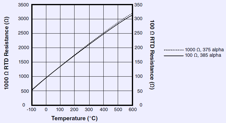
Honeywell HEL-705 RTD R/T curve graph
Common way to do this task is to perform ratiometric measurement. If we have known resistance, RREF, than this can be used as a reference against unknown resistance, RX, which is resistance of RTD, in our case here. It’s important to have good accuracy of the reference resistance, as it affects the RX measurement directly, and temperature measurement as result. It could be easy approach like using the best possible resistance standard for this task. But that would be very expensive, bulky and non-practical.
https://www.google.com.tw/url?sa=t&source=web&rct=j&url=http://www.ti.com/lit/pdf/snoa838&ved=0ahUKEwjkk-Xu-NLKAhVlPKYKHbhMB20QFggfMAI&usg=AFQjCNH4UZ_oUxzvkHtvbpenAGkS8uAUTQ
So, let’s try few resistors as reference and test how much error would be resulting from the imperfect RREF, using ADS1262 ADC as measurement device. As part of experiment, let’s also test internal current source and check how accurate it is for this task.
Experiment 4 : Simple milliohm-meter
Thanks to integrated PGA and flexible front end it’s easy to make low-resistance measurement device with little help of external current source. Most multimeters are limited for low-resistance measurement application, having minimum resistance range 20 or even 200 Ω. By using external precision current source, and high gain of ADS1262 PGA, we can make simple meter which can be useful for measuring shunts and contact resistances. Input ranges and protection will be covered in this experiment as well.
- EVM located in foam chamber box to allow control over ambient temperature.
- Two copper binding posts were connected to AIN0 and AIN1 for easy DUT connection.
- Overvoltage clap circuit placed at analog input to protect ADC in case of open connection.
- Battery-powered ultra-low noise LDO was used to power ADC with +2.5/-2.5/+3.3VDC.
- TEC module with heatsink and small fan located in chamber box
- TEC SMU controlling temperature in chamber box from +20°C to +65°C using Honeywell HEL-705 platinum RTD
- Keithley 2400 SMU used in current source mode, providing 100mADC at input terminals. Compliance voltage set to 100.00 mVDC to meet ADS1262 PGA requirements.
- Various shunts and resistors were connected
- HP 3458A DMMs were used to check DUT resistance in 4Wire mode and calculate accuracy
- Keithley 182 nanovoltmeter used to check resistance voltage for comparison
- Raspberry Pi interfacing both GPIB instruments and EVM ADS1262
Offset zero and gain calibration was performed prior to doing any test.
| Device under test | Input range | Setting | CSV-datalog | FFT | Std.Dev | RMS value | HP 3458A DMM reading | Keithley 182 nV reading | |
|---|---|---|---|---|---|---|---|---|---|
| I | Copper wire short | ±0.078V(A=32) | AIN0-AIN1 Differential | ||||||
| I | Copper wire short | ±0.156V(A=16) | AIN0-AIN1 Differential | ||||||
| I | 1.000R Vishay resistor | ±0.156V(A=16) | AIN0-AIN1 Differential | ||||||
| I | 0.100R Vishay resistor | ±0.156V(A=16) | AIN0-AIN1 Differential | ||||||
| I | 0.022R ORS resistor | ±0.078V(A=32) | AIN0-AIN1 Differential | ||||||
| I | Reed relay contact | ±0.078V(A=32) | AIN0-AIN1 Differential |
High gain of input preamp allows to measure low resistances with good accuracy, which is often very hard task for general purpose and even benchtop DMMs.
2.5В ±2.5 × 10⁻⁶
2.5В ±10 ppm
Projects like this are born from passion and a desire to share how things work. Education is the foundation of a healthy society - especially important in today's volatile world. xDevs began as a personal project notepad in Kherson, Ukraine back in 2008 and has grown with support of passionate readers just like you. There are no (and never will be) any ads, sponsors or shareholders behind xDevs.com, just a commitment to inspire and help learning. If you are in a position to help others like us, please consider supporting xDevs.com’s home-country Ukraine in its defense of freedom to speak, freedom to live in peace and freedom to choose their way. You can use official site to support Ukraine – United24 or Help99. Every cent counts.
Modified: Jan. 31, 2016, 5:51 a.m.