Contents
- Warnings & Disclaimers
- EVGA KINGPIN Edition Series features
- Software for Pascal overclocking
- BIOS & Tools
- Watercooling compatibility
- LN2 Extreme OC cooling compatibility
- Overclocking methodology for Pascal
- VRM design overview, available tuning and hardware controls
- DIY RGB lights for waterblock setup or casemodding
- Summary
Intro
This is no usual review of a graphics card, it is an uncorking OC guide focused on the technical details of device design and OC features. Before you dive in it might be worth to refresh your memory with the previous series of OC guides:
- Removing power limits on any NV card
- Using Raspberry Pi to control EPOWER VRM
- Reference GTX 1080 Ti – Uncorking bigger Pascal
- Reference GTX 1080/1070 – Uncorking Pascal
- EVGA GTX 980 Ti K|NGP|N OC Guide
- Reference GTX 780/780Ti – Big KEPLER
- EVGA GTX 680 Classified – Uncorking guide
- Reference GTX 680 – Uncorking KEPLER
Warnings & Disclaimers
Consider everything given below as “educational material” and provided AS IS to aid in the understanding of the true power in your shiny new KINGPIN-branded card. Proceed with caution and at your own risk as only you are responsible for the possible outcome of out of spec stress.
Overclocking/overvoltaging your EVGA GeForce GTX 1080 Ti KINGPIN graphics card disregarding type of the cooling, is quite an adventure and safe for the hardware, as long as it’s done correctly. Always pay attention to details and fully research these topics before doing any VGA alterations.
Having patience and doing things in small steps is key. Testing after each and every modification will provide the best user experience while keeping your hardware safe and benching over and over again. Data provided in this guide was verified on multiple cards, but slight variations in numbers or results for KP 1080 Ti graphics adapters are still possible due to silicon variances in samples.
EVGA does allow the end user to perform a standard replacement of the fan-sink on the graphics card without loosing the product warranty, but that only applies if the device was not stressed under extreme overclocking and over-voltage abuse. RMA inspection along with circuitry on the card can reveal these facts. Always be honest and responsible of your actions with this enthusiast product.
EVGA KINGPIN Edition Series features
Since the introduction on the GTX 780 Ti platform some years ago, the KINGPIN Series of graphics cards from EVGA offer some special mix of features not present on any other solution:
- Out of the box ready for any type of overclocking. From everyday gaming and compute to liquid nitrogen competition benchmarking.
- Unlimited onboard DC-DC regulator, using only the state of art components with digital control.
- Single slot display outputs layout.
- Watercooling options with custom RGB full-cover block.
- Improvements for VRAM memory overclocking.
- Advanced controls and tuning knobs for overclockers and hardcore enthusiasts.
- NEW iCX cooler technology with exclusive KPE theme.
- True dual-slot fansink for 3/4-way SLI options.

Image 1: EVGA GeForce GTX 1080 Ti KPE front view, assembled
EVGA Project 180, or simply GeForce GTX 1080 Ti KINGPIN is no exception of the lineup. The feature list has been expanded to include:
- Clean 2×8 pin power plug connectors located at the bottom right corner of the card help to minimize chassis cable clutter.
- Gold-plated copper core edge metallization on a 12-layer PCBA for improved thermal and electrical performance.
- Improved iCX fan-sink design with stacked thermal pipes, triple fan frame, 11 thermal sensors, and pure copper GPU fin section.
- 4th-generation adjustable digital VRM solution for all main voltages.
- User upgradeable ECU with firmware flexibility for future upgradability.
![]()
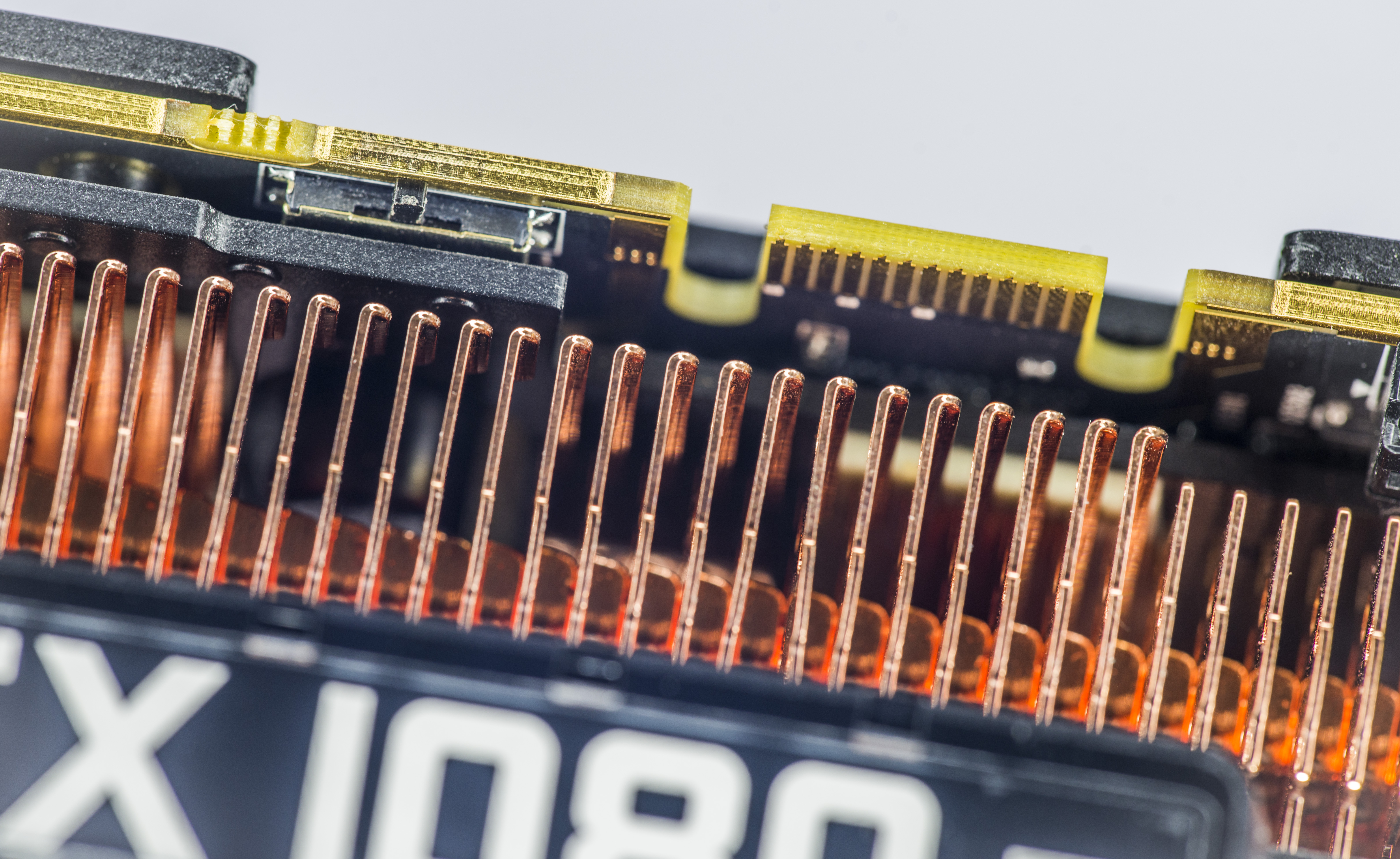
Image 2-3: PCI-Express host edge connector, edge-plated PCB and triple BIOS switch
EVGA put a lot of effort into a new iCX fan-sink module for this card to ensure that with decent case airflow it would be possible to maintain this optimal temperature even with overclocking. Many features come into play to make this goal achievable. Some of these highlights include:
- Solid copper heatspreader with six soldered heatpipes.
- Full copper GPU fin section to increase thermal capacity during peak power loads.
- Copper-plated aluminum fin section above VRM area with thermal contact to the baseplate to ensure low VRM temperatures.
- Gold-plated solid-copper PCB edge boundary for additional internal layer thermal dissipation.
- Triple iCX fan array with multi-zone thermal sensing for high efficiency at low noise.
- Clear airway on I/O bracket with single-slot display ports location (three mini-DisplayPort 1.4, 1 × HDMI 2.0 and Dual-Link DVI-I)
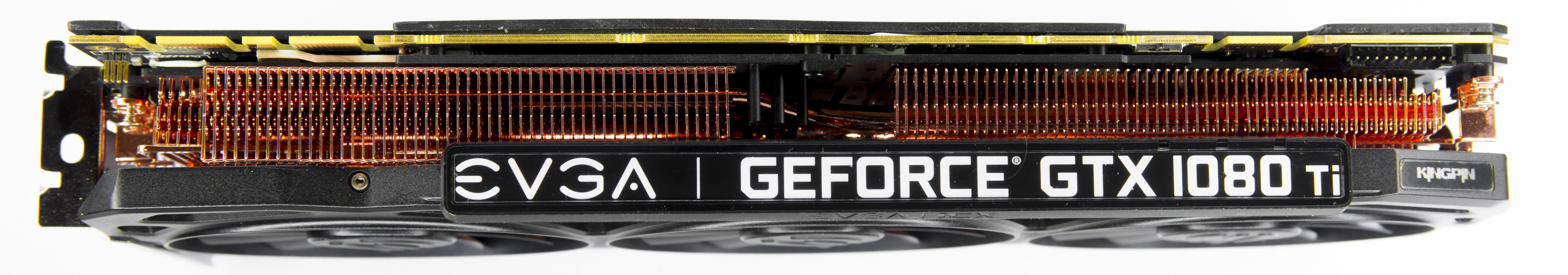
Image 4: Top size of the graphics card. Nameplate feature full-color RGB backlight
KP1080 Ti has a maximum 2 slot width to allow more options for 3-Way and 4-Way SLI setups. More practical benefits of a increased spacing is better compatibility with packed hardware configurations. It’s not rare to find content-creation HEDT platform with a few high-speed PCI-Express SSD drives, PCIe audio cards or multi-port RAID HBA and 10 GbE PCIe NICs. Video content creation in VR and high 4K/5K HBR and even 8K resolutions systems demand highest performance available.
This fansink works best with a well-ventilated chassis including large open areas for quick heat dissipation. All the main thermal surfaces including fin sections and back plate are coupled with thermal pipes and thermal pads for good thermal conduction from the active circuitry on the PCBA.
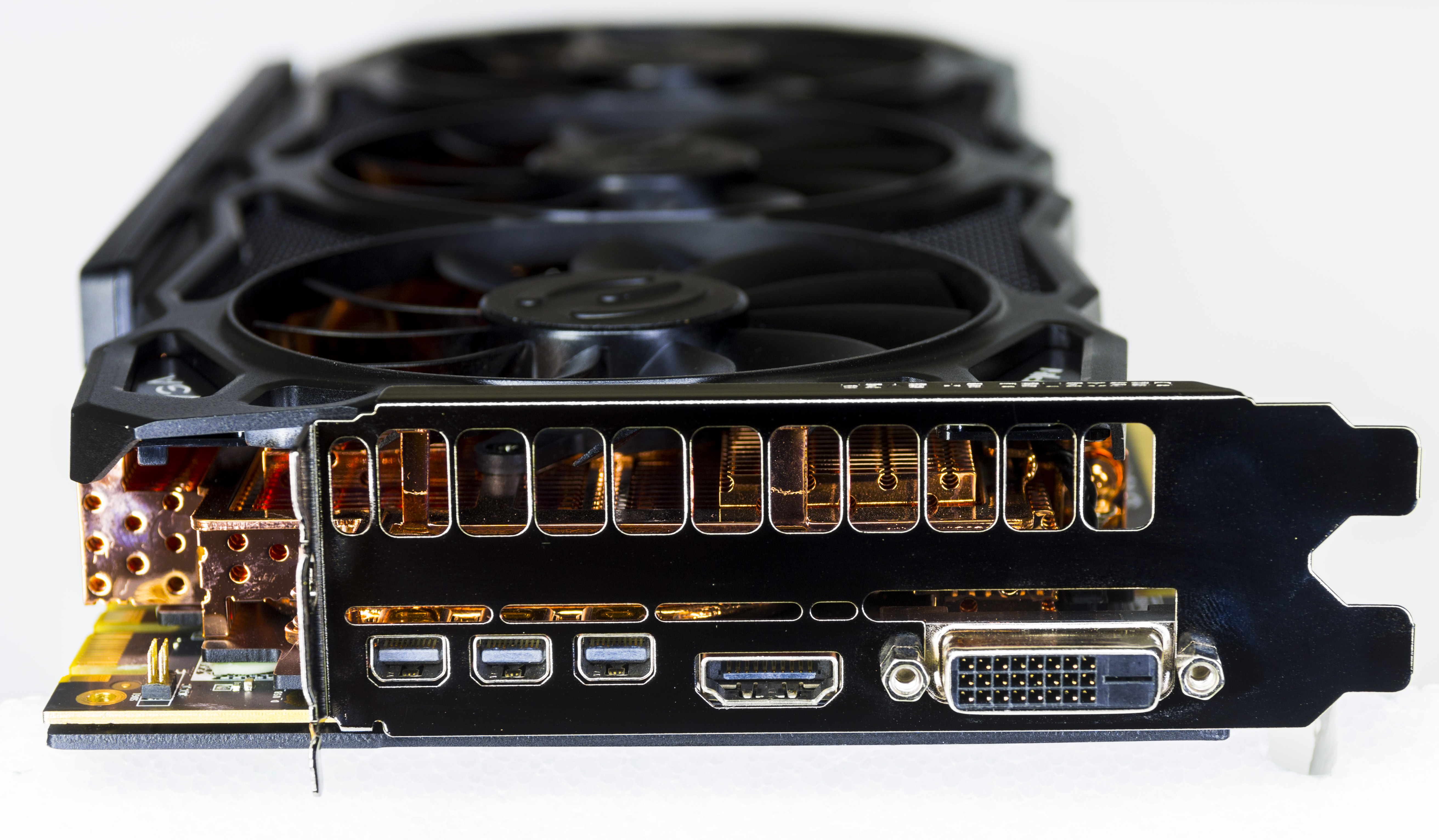
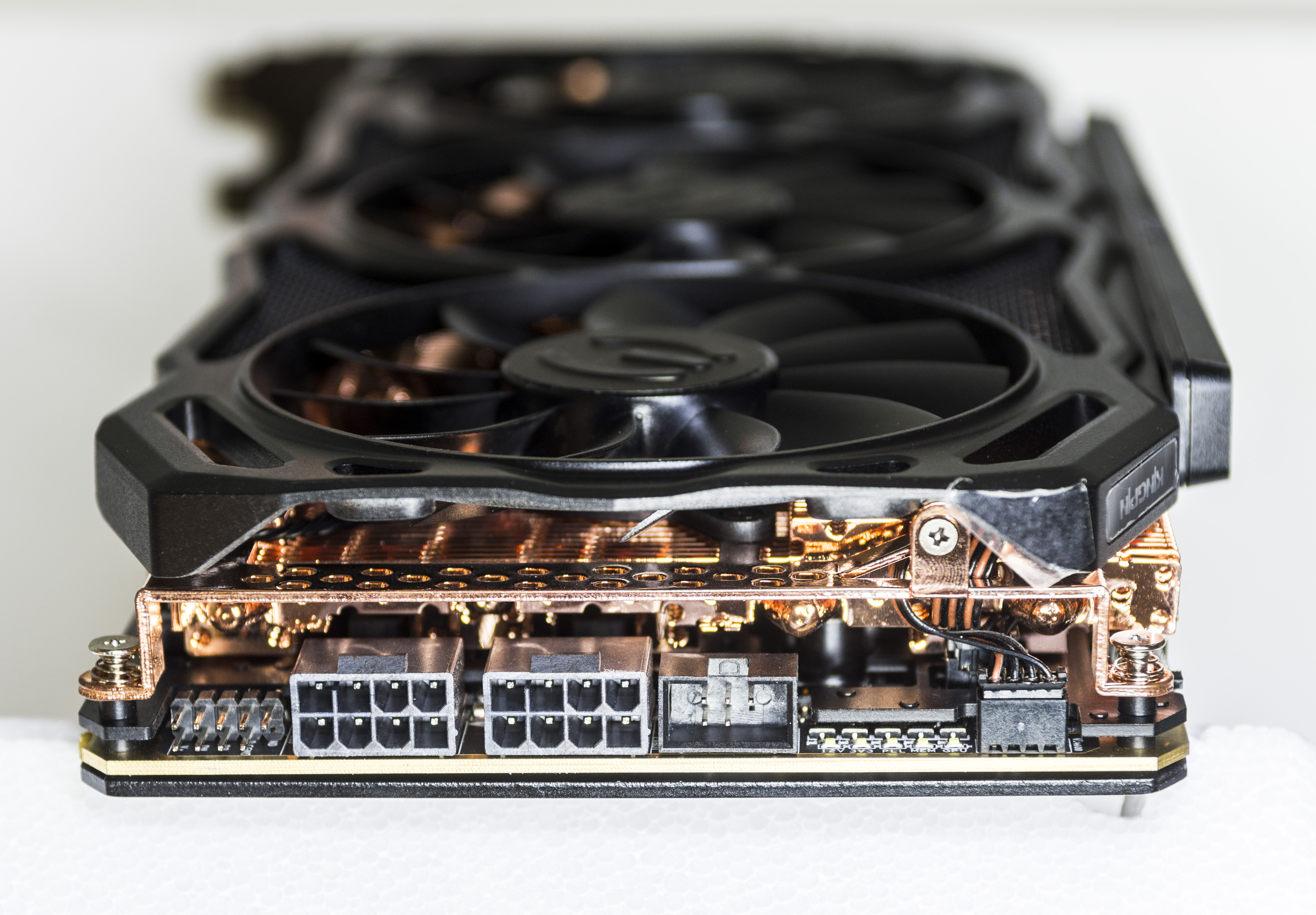
Image 5-6: Display I/O panel and rear power and interface connectors
Front I/O connections follow the same layout as on previous cards of this series, featuring full support for Pascal GP102 available outputs. Any four outputs can be used simultaneously from one card and the card is bundled with some mDP-DP and mDP/HDMI adapters.
- 3 x mini-Display Port 1.2/1.4 ports.
- 1 x full-size HDMI 2.0b with HDCP 2.2 port.
- 1 x Dual-Link DVI-I digital only output.
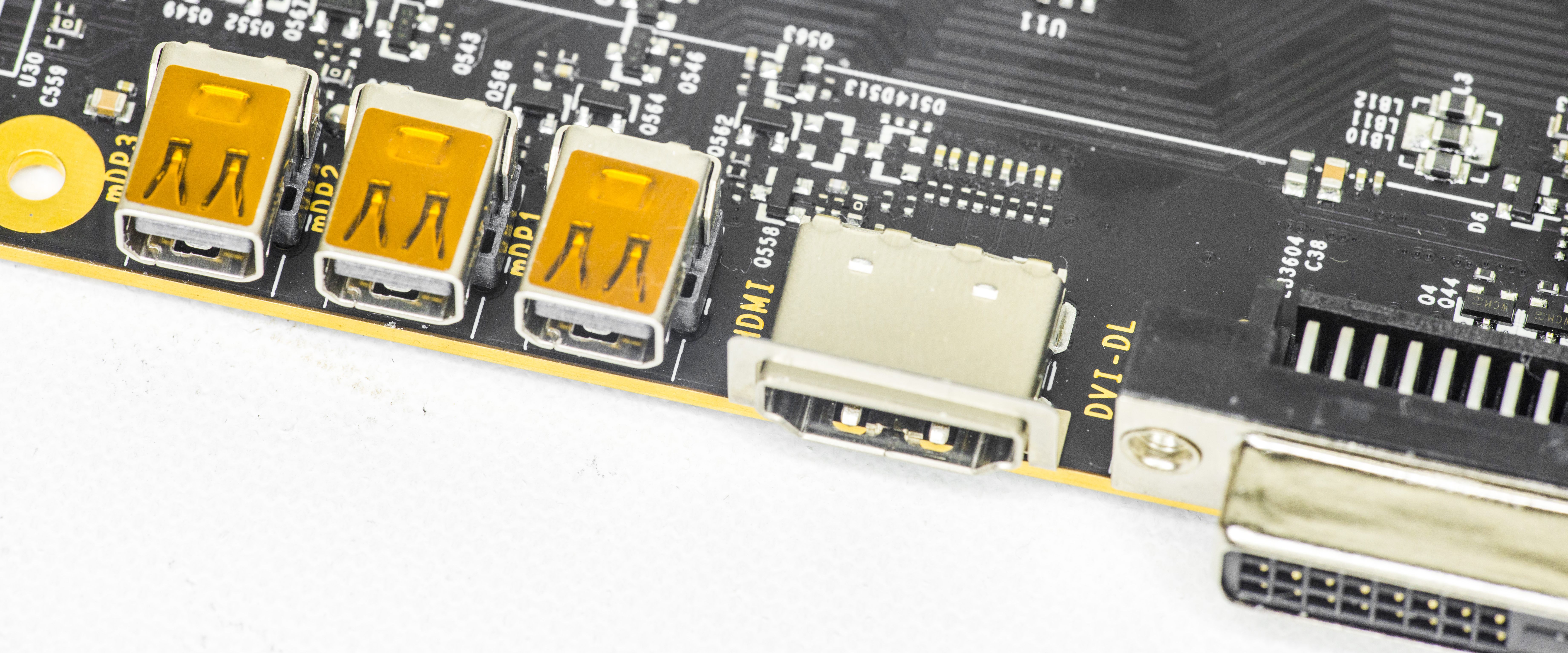
Image 7: Single-slot position for all display interfaces
Pascal GPUs do not have RAMDAC and analogue circuitry anymore, so there is no support for passive VGA adapters. If you really need analog VGA connectivity you can do so by using a more expensive active dongle.
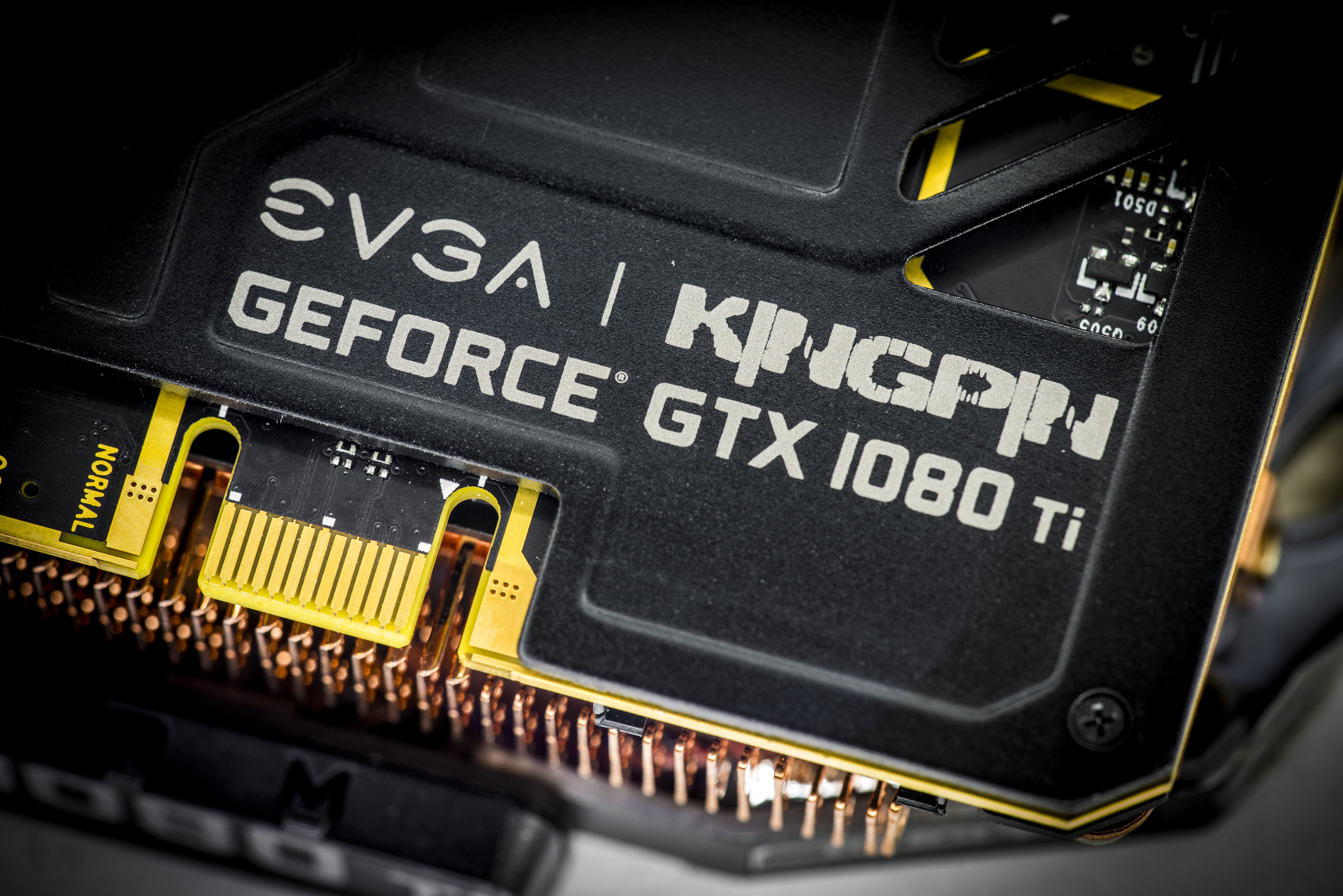
Image 8: GTX 1080 Ti KINGPIN custom backplate artwork
Custom backplate is stock on all KINGPIN 1080Ti cards. It covers the rear of the circuit board with thermal pads both behind the GPU core and GDDR5X memory areas to avoid heat being trapped under the solid cover.
Backplate is mounted to the card and fan-sink baseplate by using 18 small Philips-head screws.
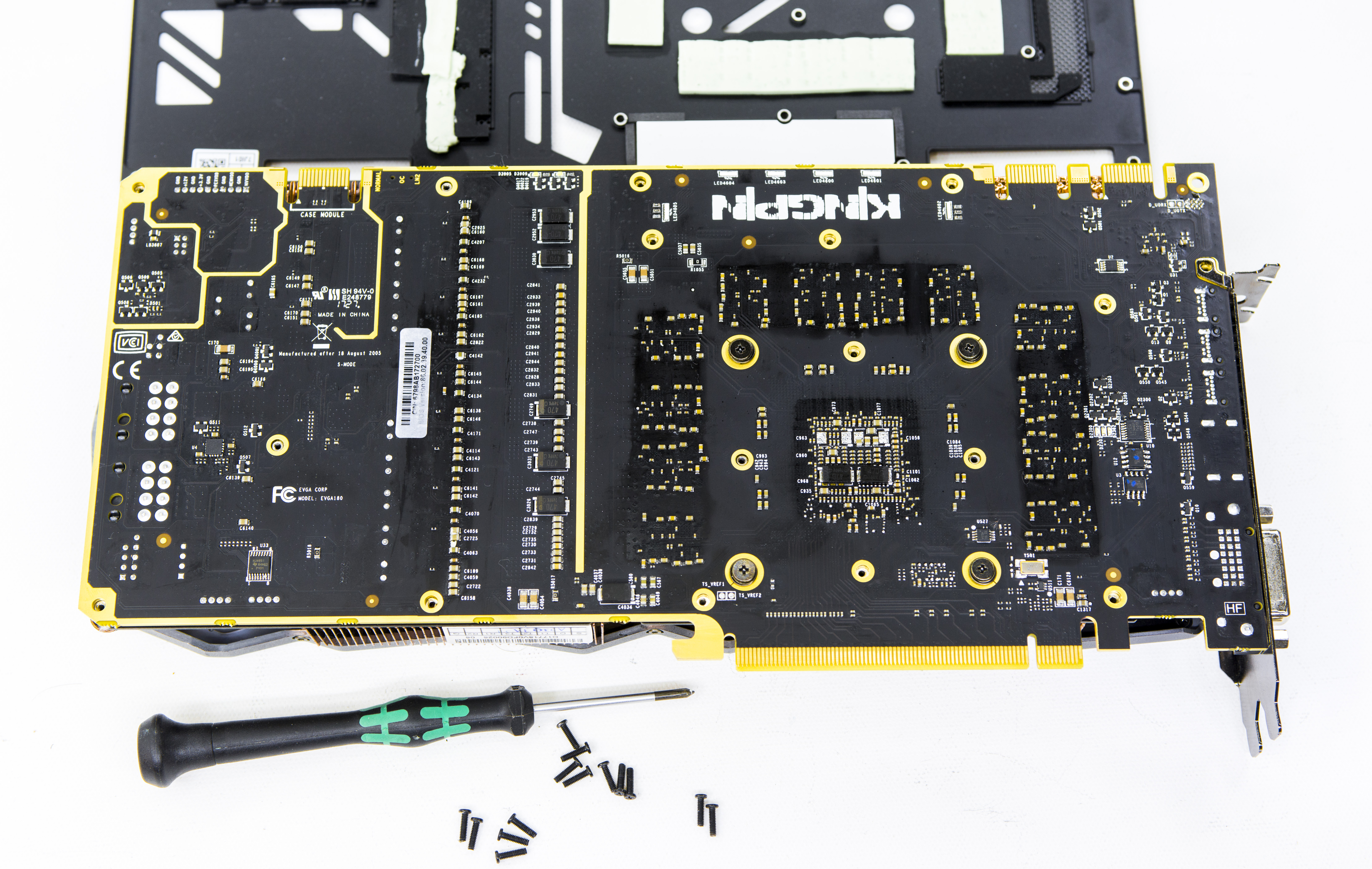
Image 9: Removing backplate and rear side overview
Modular VRM baseplate section can and should be be further separated to allow aftermarket cooling assembly on gpu while still using vrm plate.
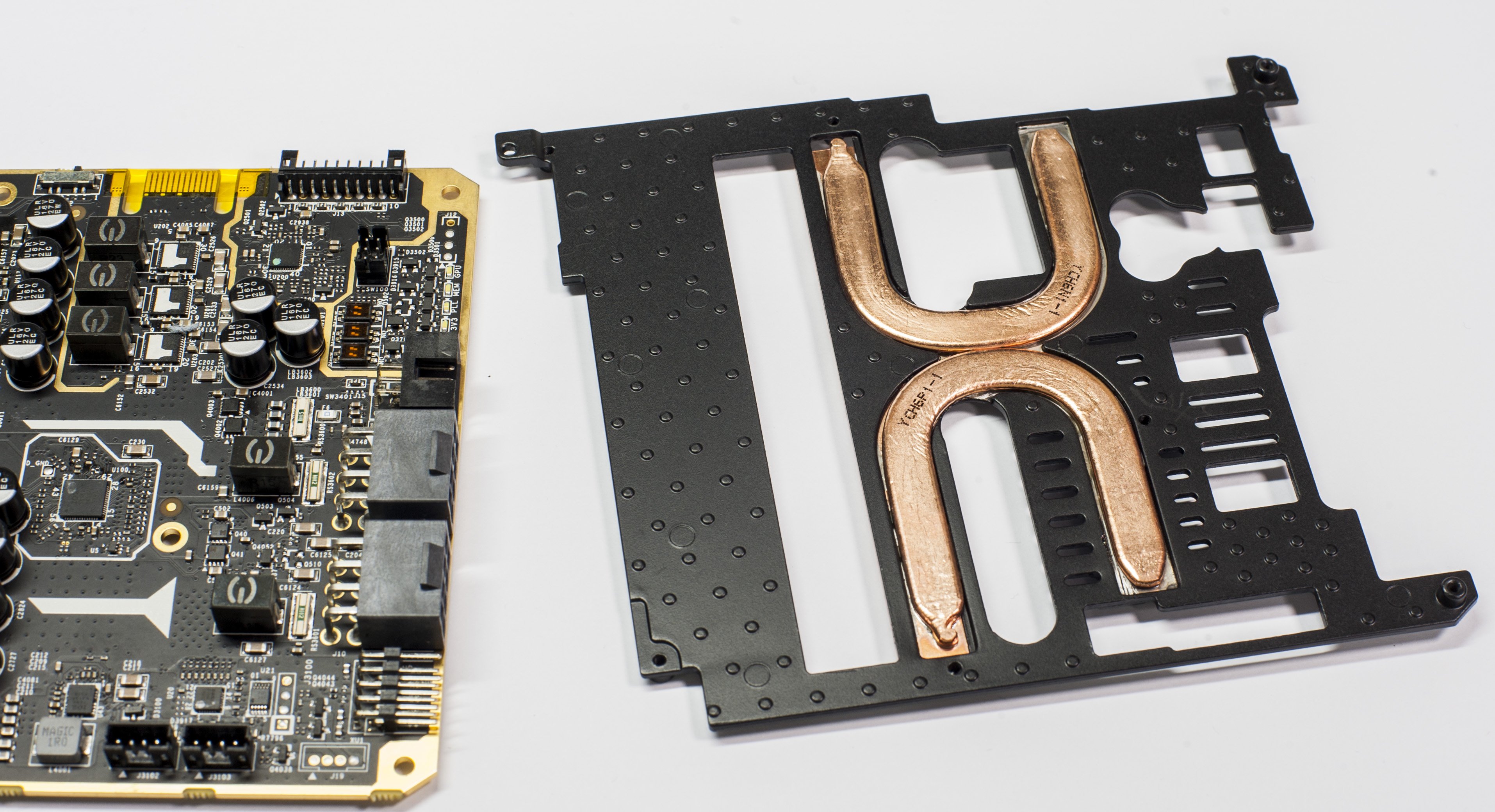
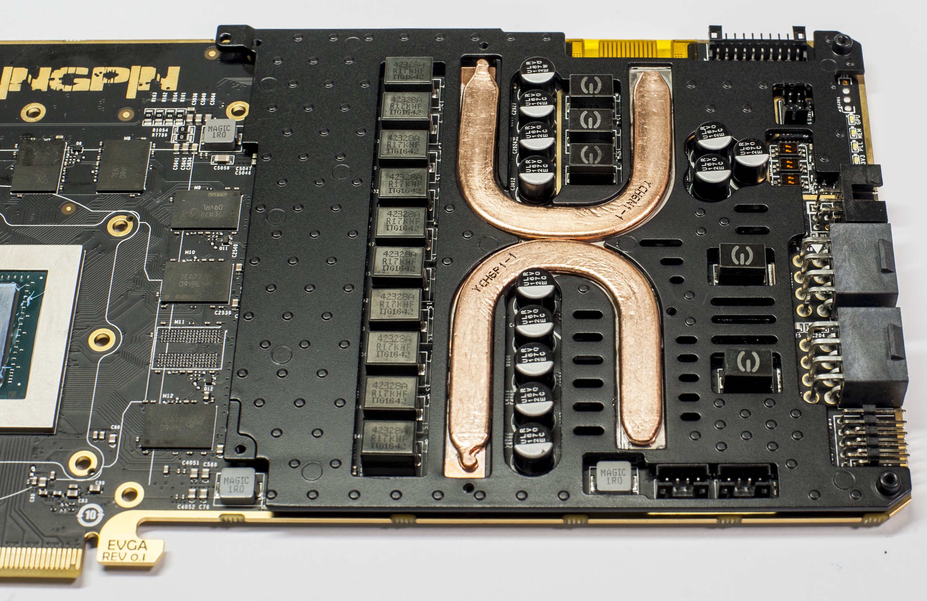
Image 10-11: GTX 1080 Ti KINGPIN VRM backplate
Software for Pascal overclocking
Succeeding the GTX 1080 series are the GTX 1080 Ti FE, various NV Titans, and now mighty Pascal GP102 with custom board designs and high-end performance cooling solutions. Even with such a large amount of shaders, these GPUs have the ability to boost clocks to 2000 MHz and beyond. Does this mean that all the overclocking margin is already claimed by NVIDIA and partners with the end user having nothing left to enjoy?
Not exactly, however getting more without loosing stability does require careful tuning and good understanding of the present limitations of all components. As with previous OC uncorking guides, we cover a few with the basics of available tuning controls.
Power target and OC settings
TGP or more typical term “power limit” is the main item to handicap performance. Every NVIDIA card since the Kepler era has a power limiter and special associated circuitry on the PCB to measure and regulate input power. This control traditionally does not give you any amps or Watts value, but instead provides a percentage over design specification(which varies depending on card SKU/vendor!). Attempts to compare 130% limit value of card A to 115% value of the card B will give you no useful information without the knowing actual power limit for each SKU.
If you want maximum OC headroom on air/water it is best to use OC BIOS switch position(Orange)and max TGP + OV setting in Precision XOC. It will be enough to maximize the performance on ambient cooling levels.
Next up are the usual controls we use in EVGA Precision XOC for adjusting everything on the card in windows:
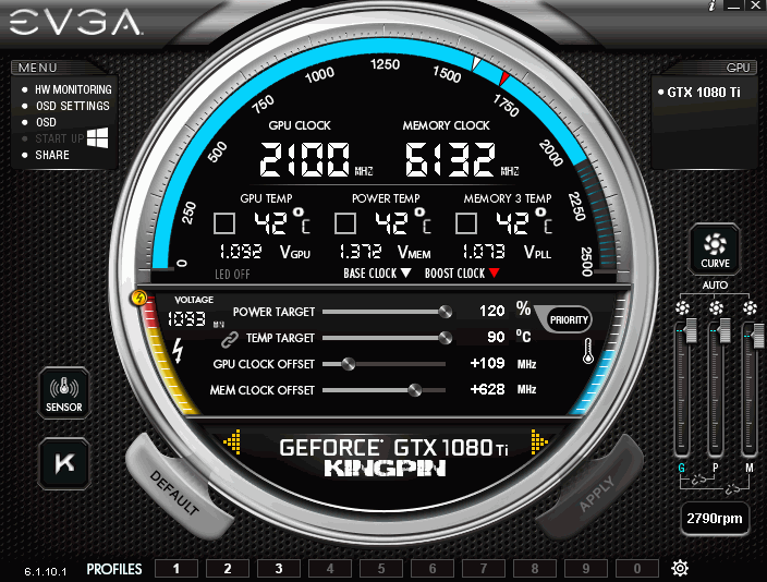
Image 12: EVGA Precision XOC GUI with EVGA GeForce GTX 1080 Ti KINGPIN
- GPU Clock offset – This is GPU core clock adjustment setting. Increase to get higher maximum boost frequency.
- MEM Clock offset – This is memory clock adjustment setting. Increase to get higher memory frequency.
- Voltage slider – for increasing the power to the core (depends on VID, 1.09xV-ish limit in Precision XOC). Use other tools for higher.
- Fan speed, for each fan – Always max these when pushing the card on air cooling.
- K-Boost – This is good for getting the best scores when pushing the limits.
K-Boost mode sets the driver to P0 max boost state on a SW level and can prevent the card from switching back to 2D clocks in between power states(game test changes) while running benches. This can hurt the overall FPS in a benchmark, and usually results in a slightly lower score. On LN2 its necessary so always use K-boost or other method for fixing max perf pstate when doing any kind of benching for good scores!
Card controls and additional settings
With integrated OSD and profiles function, Precision XOC allows for quick setting, testing, and finetuning system during benchmark runs. GUI allows control over the OSD functions and the amount of sensor information available. It fully supports multi-GPU setups, and can work with any NVIDIA GeForce GTX graphics card.
Real voltage software monitoring
Now with latest Precision XOC and 1080 Ti KINGPIN, you don’t need a DMMon the table to enjoy true voltage monitoring. As you already know, regular hardware health monitoring software is unable to show real voltages supplied to the GPU and also disregard additional voltages like memory and PLL power. This is due to the fact that the NVIDIA driver only supports readout of “requested” voltages, or GPU VID setting. It does not have a standard mechanism to report real voltages presented from VRM. Most end users are not aware of this detail and expect to see real voltages. That’s why we often see many confused people in forums/discussions who see LN2 records with 2500 MHz+, but are often confused about reported clock/voltage measurements and left scratching their heads wondering how is such a high clock possible with only 1.093V?
No more confusion with KINGPIN 1080Ti as we have added special hardware to actually measure all the relevant voltages in real-time and report those measurements to Precision XOC which now can read and display real voltages. It works automatically with every 1080 Ti KINGPIN graphics card and does not need any settings adjustment. Just make sure you use latest 6.1.13 or newer version of the precision tool. You can always download EVGA Precision XOC, at moment of writing it was 6.1.13 (32MB).
There is no limit on reading so even 1.6V will be reported correctly now ;). Again, this works only for EVGA GeForce GTX 1080 Ti KPE cards. Other adapters like FTW3, SC-series, or any other would not show additional voltages.
BIOS & Tools
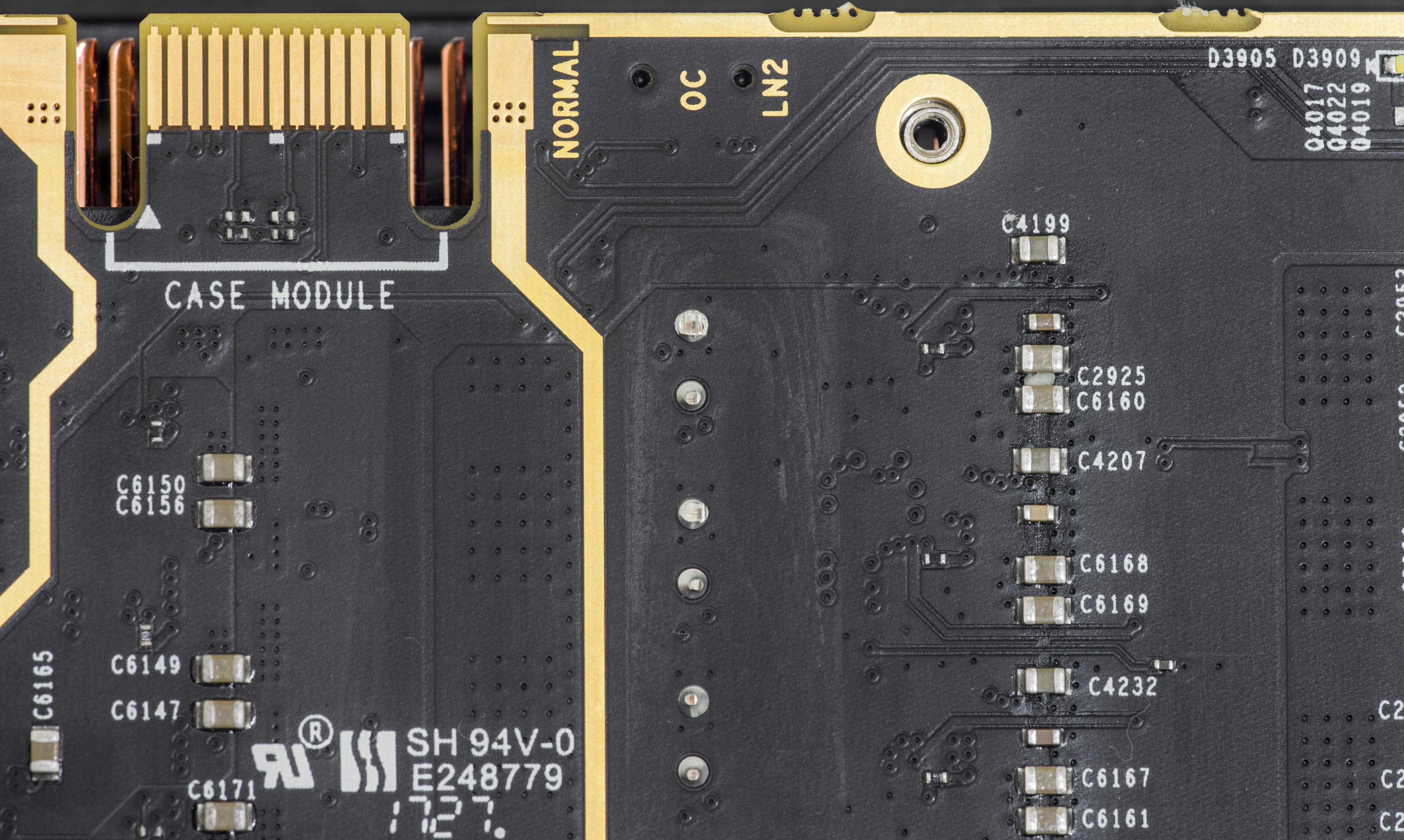
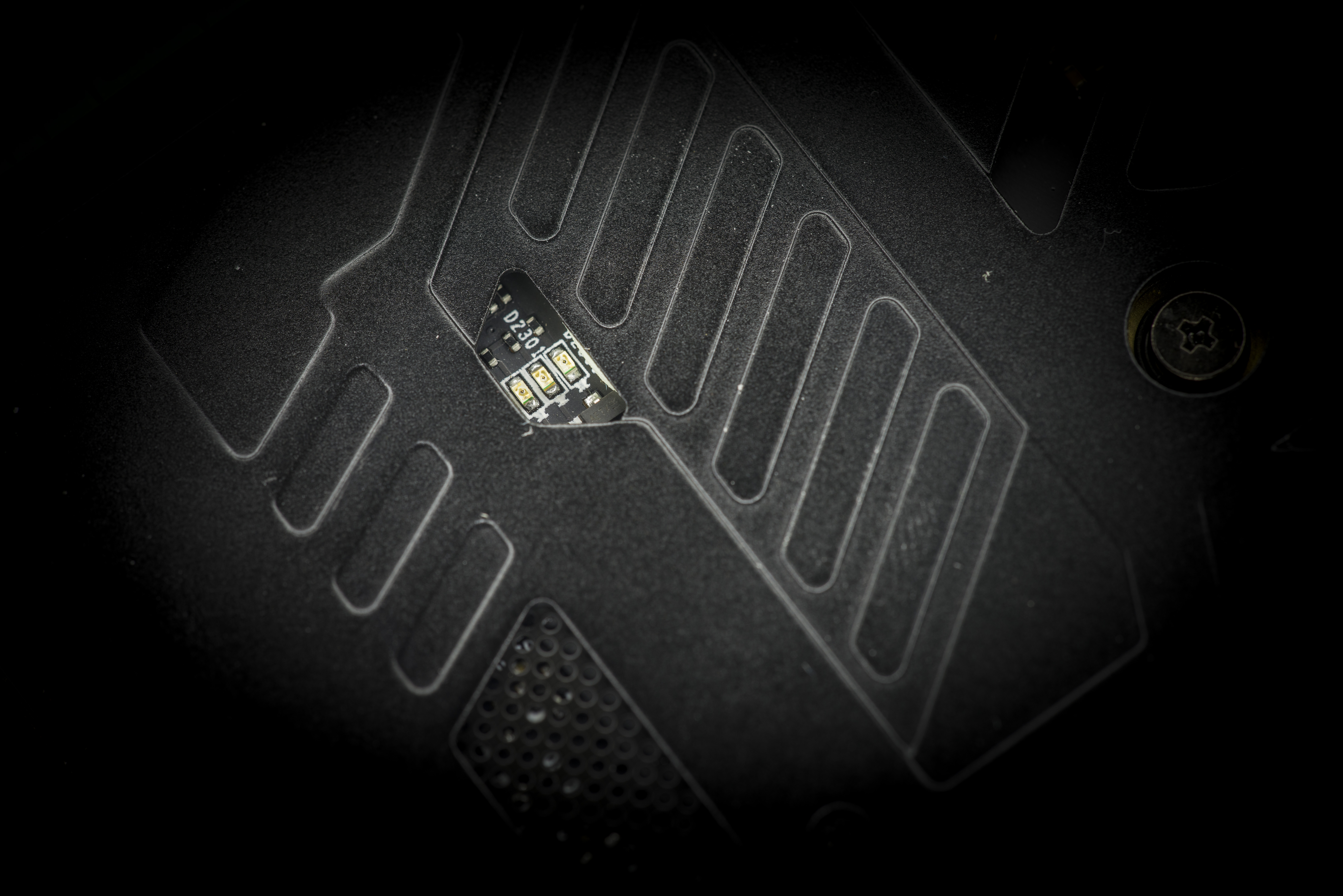
Image 13-14: EVGA180 BIOS LED location and labels
BIOSes in this section are compatible only with EVGA GeForce GTX 1080 Ti KINGPIN and will not work and may damage any regular 1080 Ti FTW3/SC or any other brand card.
As with all previous KINGPIN Edition cards, 1080 Ti KPE has three different BIOS ROMs and corresponding switch to select between them. Default configuration with switch locked at right (towards power plugs), setting on NORMAL BIOS position.
BIOS difference comparison between the three are presented in table below:
| Normal BIOS | OC BIOS | LN2 BIOS | |
|---|---|---|---|
| BIOS mode LED indicator | Green | Orange | Red |
| GPU Clocks/Boost/Memory clock | 1582/1695/11008 | Same as Normal | Same as Normal |
| BIOS Version | 86.02.39.40.90 | 86.02.39.41.90 | 86.02.39.41.90 |
| Fan profile | 0% – 55% | 8% – 55% | 8% – 55% |
| Fan stop at idle | Yes | No | No |
| Total Power Limit | 300W | 300W | 300W |
| Max TGP Limit | 120% | 130% | 130% |
| Protection function | Full protection | Full protection | No temperature protection |
Table 1: BIOS ROMs on the card
This time around the LN2 BIOS and OC BIOS positions actually have same stock BIOS and only benefit the LN2 BIOS gives out of the box is disabled temperature protection. This is crucial for LN2-type cooling, but totally unnecessary(and even dangerous) for watercooling/aircooling use. Of course any of the three BIOSes can be reflashed with unofficial BIOS ROMs and operated independently. More on this bit later :)
Card is shipped with three different BIOSes:
Normal BIOS – This BIOS is stock baseline, +120% Power target limit
OC BIOS – This BIOS similar to Normal, but more aggressive fan profile, +130% Power target limit
LN2 BIOS – Same BIOS as OC position. HW set to disable thermal protection for LN2 overclocking.
Custom BIOS
Extreme watercooling OC BIOS – Unofficial OC BIOS with even faster fan and higher power target limits
If you plan to run LN2 temps (below -100°C)you should use the LN2 switch position (Red LED BIOS), to disable the hardware thermal protection mechanism and flash XOC BIOS from link above.
Avoid running on the LN2 switch position during aircooling/watercooling. Thermal protection is important card feature to prevent possible GPU damage if fan sink is not attached properly or blocked causing gpu to overheat.
ECU Interface port
Card also have additional interface 9-pin port, compatible with standard USB 2.0 ATX motherboard header. Located right under lower 8-pin, it is currently used for EC firmware update function and diagnostics. There will be upcoming feature to use this port for additional real-time card health monitoring or XOC use.
More details to be revealed in this guide soon.
| Pin number | Pin function | Pin function | Pin number |
|---|---|---|---|
| 10 | Signal Ground | No pin, Key | |
| 8 | Power Ground | Signal Ground | 7 |
| 4 | No connect | EC USB D+ data line | 5 |
| 6 | No connect | EC USB D- data line | 3 |
| 2 | +5V USB Power | +5V USB Power | 1 |
Table 2: ECU Port pinout definition
Pinout follow standard USB 2.0 header with pin 9 removed to prevent incorrect cable connection. Interface cable between motherboard and VGA is bunded with every card.
Three individual fan headers on the card are used for iCX fansink. Connections are mapped to match fans location.
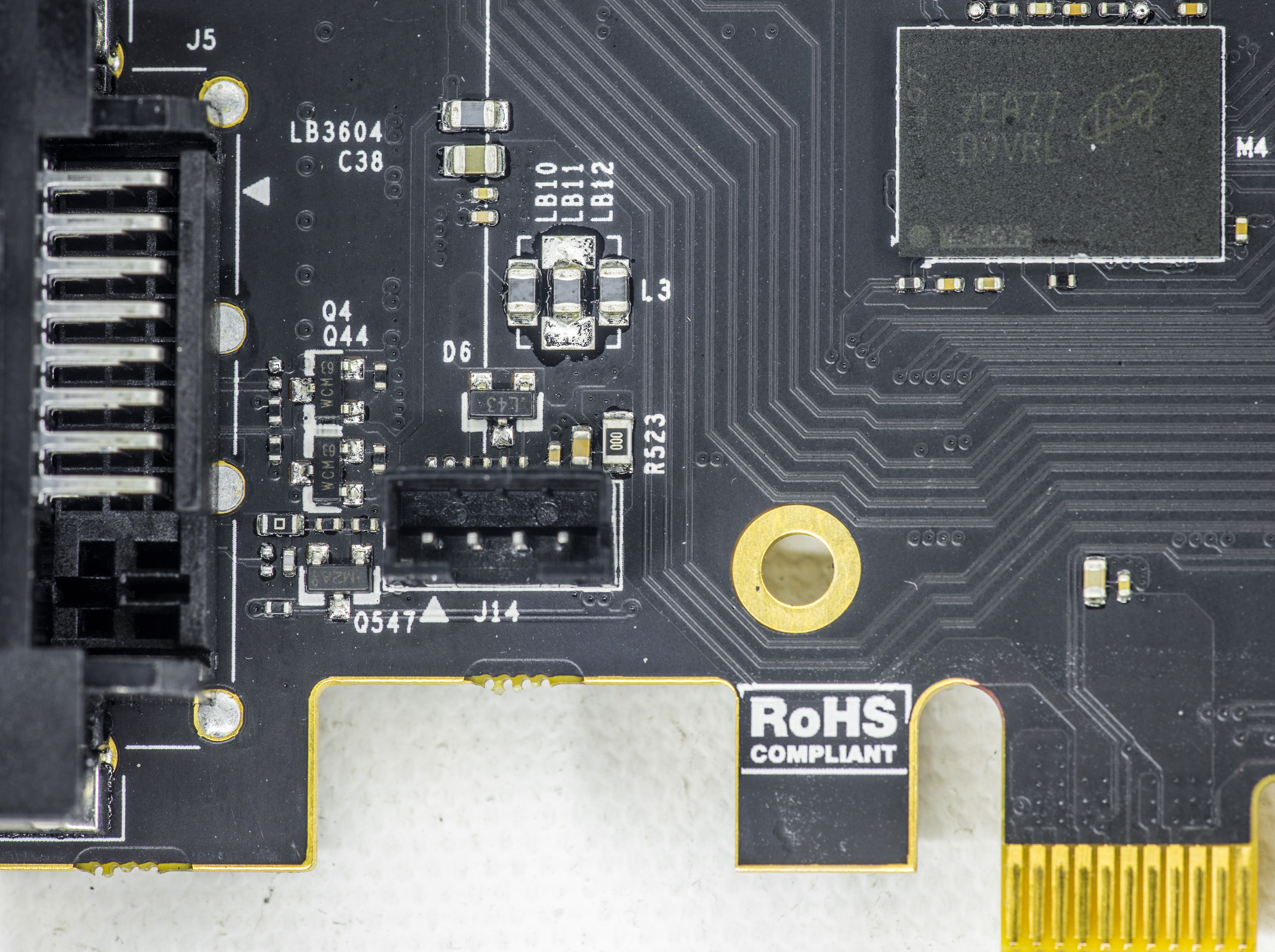
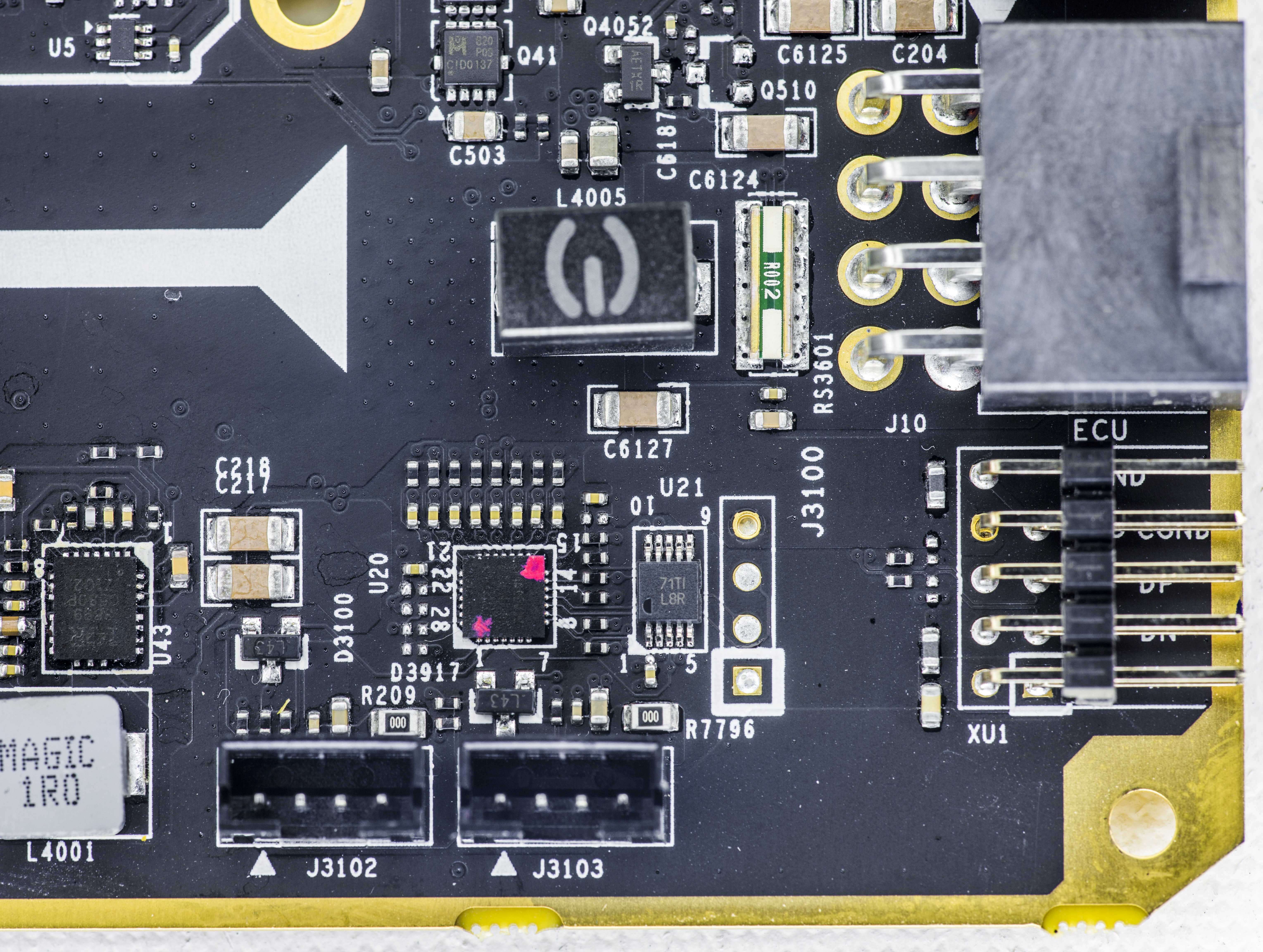
Image 15-16: Fan headers for individual control on 1080 Ti KPE.
| Fan connector designator | Location |
|---|---|
| J14 left fan, GPU controlled | Left, near DVI-I |
| J3102 middle fan, memory temperature sensor controlled | Bottom right |
| J3103 right fan, VRM temperature sensor controlled | Bottom right |
Table 3: Fan headers location and definitions
Watercooling compatibility
Single-slot watercooled HydroCopper version of the 1080 Ti KINGPIN is available at EVGA store. Bundled with card and preinstalled full-cover waterblock will be shipped, ready for loop assembly. At least 2 × 120mm radiator size is recommended, with good high performance pump, such as Laing DDC or D5, Swiftech MCP.
New HydroCopper has matched color theme of the KINGPIN card with dark metal finish and massive copper base. Cooler covers both GPU, memory and VRM sections.
LN2 Extreme OC cooling compatibility
Unlocking maximum speed potetntial from GP102 requires extreme cooling methods, such as a GPU Liquid Nitrogen container. To ensure good compatibility, there are no tall components in GPU and memory proximity.
Large container, such as Kingpincooling TEK-9 FAT works well with GP102 cooling. It comes bundled with all required mounting accessories, so just add some insulation, cover graphics card with water protection(LET) or Vaseline to avoid possible damage and you ready to go.
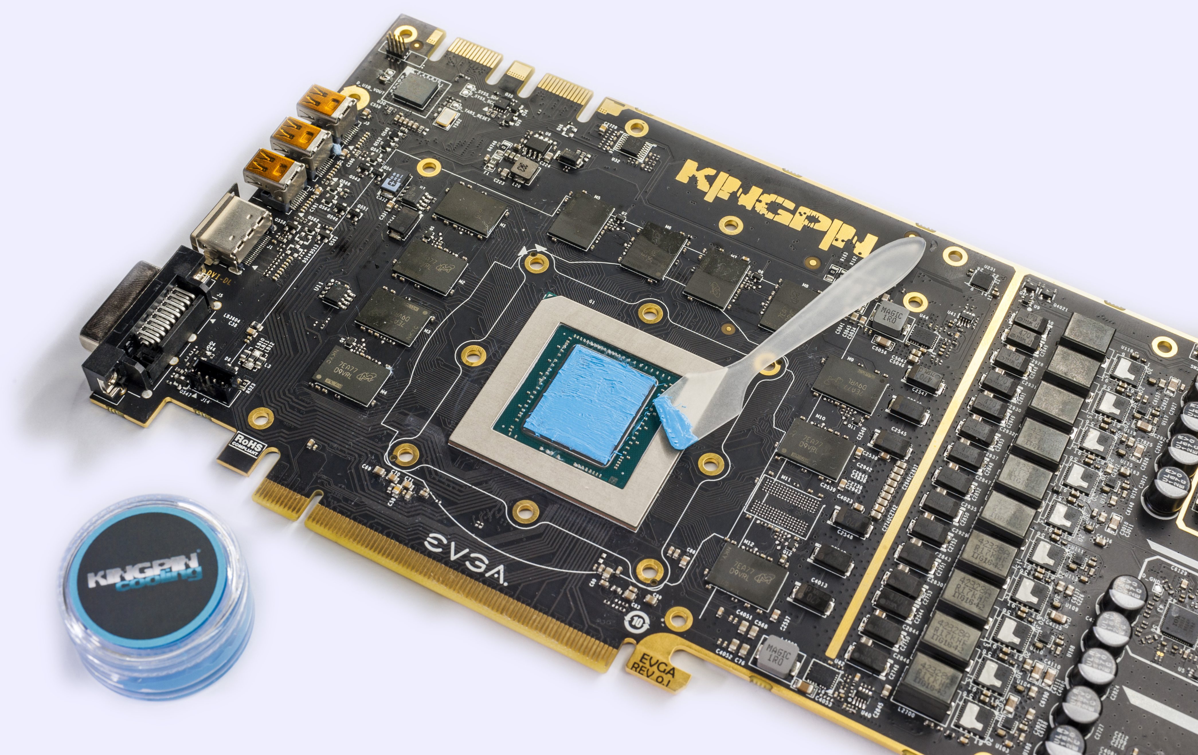
Image 17: KPx thermal grease and application on the GPU surface
A extreme cooling compatible thermal grease must be used for best performance. We get best results with Kingpincooling.com KPx grease, which has great ability to stay in place and not freeze/crack when cold. It has low thermal resistance which is ideal for GPU overclocking and it provides excellent contact filling all the air pockets around GPU die and LN2 pot base.
Overclocking of the Pascal (GP10x)
Very similar to the previous Maxwell family, NV opted to maximize out of the box performance reducing thermal and clock margins for overclocking even more on Pascal. Agressive Turbo Boost 3.0 clock profiling really demands the best possible thermal solution. W1zzard @ TechPowerUp well covered operation and dependency of running clock versus die temperature by Turbo Boost 3.0 with GTX 10×0 series cards, where we can see GPU start dropping frequency nearly every 5°C rise, with maximum frequency obtainable only with actual GPU temperatures under +50°C.
As transistor temperature increases exponentially with respect of voltage, such dense GPUs like GP102 have no gain from overvoltage on air and water cooling temperatures. Even the very best watercoolers are sometimes not able to deal with GPU heat flow. Temperatures rise from frequency overclocking and always rise in linear fashion. Voltage just adds more heat to that equation usually.
Air/water cooling clock/voltage/temperature range
With factory tuned power settings, EVGA GeForce GTX 1080 Ti KINGPIN is verified to run at least 2025 MHz under typical OC conditions (Loaded GPU temperature under +50-60 °C and power/voltage limits are maxed out in Precision XOCC). Some cards can do a few bins higher, but actual result vary per specific load/temperature profile. Watercooling allows lowest temperatures with less noise, meeting targets under +50°C easy with decent radiator/block/waterpump setup. Some gpus will benefit in OC from these low ambient temps. Depends on gpu leakage/voltage.
Clockspeeds, voltages, and temperatures all work together and must be dialed in correctly for the best results on any form of cooling. The following are the normal overclocking ranges you can expect for the majority of cards, however every card is not exactly the same due to variance in manuf silicon. More fine tuning will always get the best results on your card. Some cards will benefit from more voltage to reach same clocks, while others would be harder to run with any increase. The thermal part is the bottleneck and as suggested earlier, overclocking in small steps helps to learn exactly what your particular GPU needs can yield best results for every MHz upward.
The cards clock range on AIR cooling using the pre-installed 1080 Ti KINGPIN iCX cooler WILL VARY and these are only guidelines of what the average card will do. Using benchmarks like 3Dmark FireStrike or Unigine Heaven while keeping cool ambient temps with GPU temperatures under +50-57°C one can reach max boost clocks the card is capable without throttling from the NV driver usually. Over 2050 MHz is quite possible on 1080Ti KP, with at least 2025 MHz expected. Best cards can hit approx 2100 Mhz with proper ambient temps. If you manage to cool GPU even better (e.g. using high-performance custom watercooling loop or chiller) you can have the best chance to reach 2088-2100 MHz under stable 3D loaded conditions.
LN2 cooling clock/voltage/temperature range
Pascal GPUs on KINGPIN Edition can go to the limit and are capable to hit 2600 MHz+ core frequency with the right amounts of voltage and stable sub zero temperatures(-140°C or colder). Fully maxing out these GPUs on LN2 usually requires around -155 to -195c on the GPU container, and roughly 1.50v-1.60v under load at DMM/monitor. The thermal grease you use and the mounting accuracy/pressure also has a big impact on max clocks. It’s critical that the contact surface areas of the pot and the GPU are parallel and mounted with sufficient even pressure in all corners, or you can lose 100-200 MHz+ on top end. Bad mounting and poor thermal grease for LN2 can cause a large temperature delta between the GPU pot surface and the die temp on the GPU itself. With 1080 Ti KINGPIN, there is an internal monitor so you can actually check the delta of the card to see the contact accuracy and grease viability(frozen or not). These two aspects are CRUCIAL to top end GPU extreme overclocking. Both are covered later in the guide.
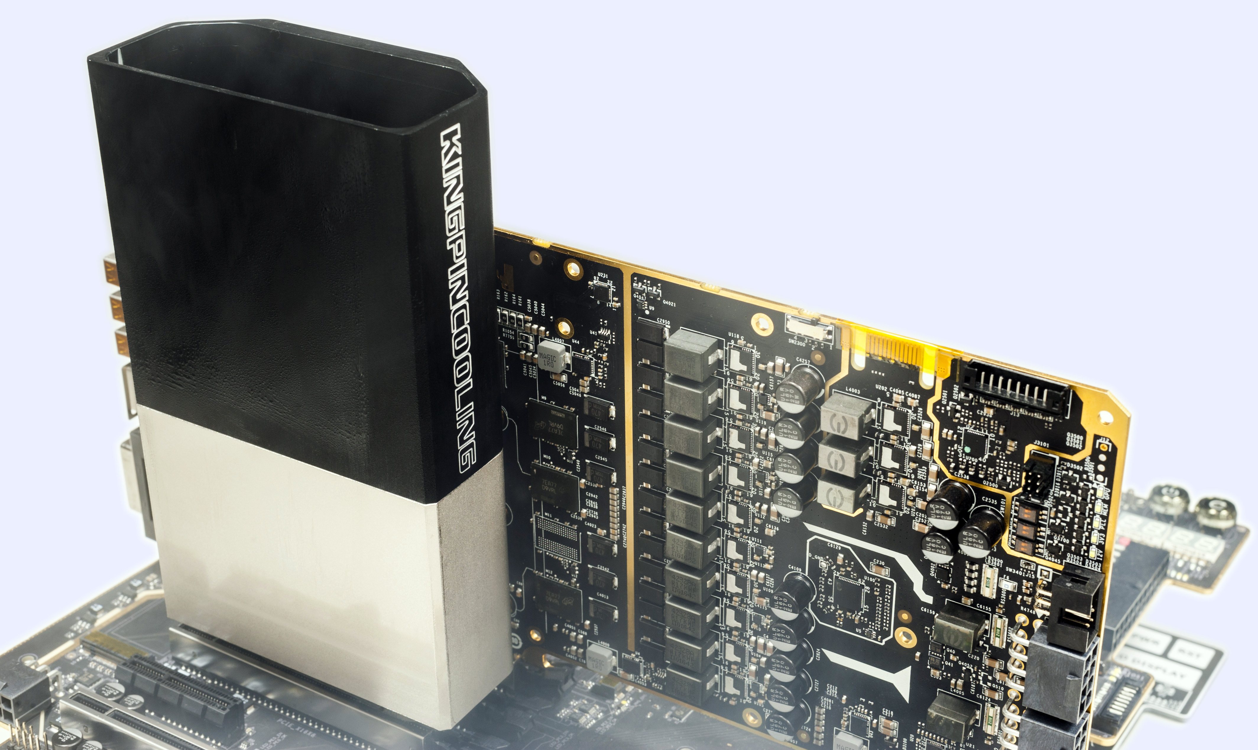
Image 18: KPE with installed Kingpincooling.com TEK-9 FAT copper block
This guide doesn’t cover insulation and condensation preparation of the card itself, as there are different ways to do this and everyone has a preferred method. You decide how you want to insulate your card your own individual way. Check around KPC or the usual internet forums for usual insulation/pcb preparation guides for your graphics cards. Once the 1080 Ti KP is prepped, container mounted, and card installed into the system you’re ready. ALWAYS do a quick post/boot before putting ANY LN2 into the container just to be sure everything is still 100% functional on the card after you mounted it. Check that the drivers are still working/installed, check for artifacts on the screen, even run a 3Dmark at default settings. If the container warms to 30-40 °C under load, just splash it with some LN2, don’t let it overheat is all you really need to worry about. If it can’t pass this test, it will never overclock on LN2 and getting past this part will ensure you won’t have to break down the rig after frozen and start over.
If everything is OK then let’s move on, but word to the wise: You can NEVER just pull the card down to minimum – temp (like -196 °C), set max voltage(1.65v+) and think it will run alright. This is NEVER recommended and something I’ve always preached against since the beginning. Impatience will lead to bad extreme overclocking sessions and likely ruined hardware. The proper way to overclock a VGA to the max clocks it can run is to go in steps, working your way up in voltage and down in temperature, like the following. Adjustable on the fly Vdroop changes can help when tuning in max clocks. Voltages shown are measurements taken at the Probe It reading point for core voltage:
| STEP 1, first 30-60 minutes | 1st boot/check with near zero temperature | ~2000 MHz, Default or 1.2-1.3V |
| STEP 2, -40 to -60 °C | 2200 MHz | 1.35 VGPU, 1.45VMEM |
| STEP 3, -90 to -100 °C | 2400 MHz GPU, +600-800 MHz memory | 1.45 VGPU, 1.45VMEM |
| STEP 4, -120 to -140 °C | 2450-2500 MHz GPU, +800 MHz memory | 1.5 VGPU, 1.45VMEM |
| STEP 5, -160 °C and beyond | 2600 MHz+ GPU, +800-1000 MHz memory | 1.5V+ VGPU, 1.50VMEM |
| STEP 5, Warmup back to ambient | 2000 MHz / default | 1.4 VGPU, 1.45VMEM |
Table 4: Extreme overclocking steps and guidance
Again these are typical steps and LN2 scaling numbers of what most 1080 Ti KINGPIN cards can achieve. While KP 1080 Ti PCB design is indeed capable to push GP102 GPU to it’s limits, the actual result still varies per specific GPUs silicon samples and system/configuration + benchmark used. Factors such as chip leakage, thermal grease quality and container mounting pressure can and will have a impact on the end result.
GDDR5X Memory overclocking
In modern benchmarks like 3Dmark Time Spy/FireStrike or Heaven, graphics memory overclocking is just as important as the GPU OC, if not more. Our pretesting on pre-production samples revealed expected overclocking on memory +800MHz, with good cards going all the way to +1000MHz on memory frequency. Much thought was given on 1080 Ti KINGPIN with regards to memory performance during the card design to get the best performance balance from both GPU and memory together. This key for optimal pascal performance.

Image 19: GTX 1080 Ti KPE memory layout and Micron IC photo
Since GDDR5X memory is exclusive to Micron, KINGPIN this time sports the same Micron MT58K256M321JA-110:A memory chips, in standard 11 GByte configuration. These Micron chips are rated for 11.0 Gb/s data rate and designed for 0-95°C temperature range running at nominal 1.35VDDQ ±3%. Maximum stable memory frequency can scale a bit with memory voltage, especially when well cooled. This means that if you provide a slight bump in memory voltage, at around 1.50V, you may be able to squeeze a hundred or two more MHz on memory clock without loosing benchmark stability. When you are overclocking on LN2, you want to match the highest core speed + highest memory speed. This is what gives the best score. Also elevated memory voltages help to keep the GPU’s memory controller from flaking out on extreme cold thus limiting max memory OC.
Keep in mind that the cards memory is calibrated and trained when it initializes and the boots windows. Sometimes when raising memory voltage higher for example to 1.5V in one big step while at idle desktop, it can cause the GPU to lock and artifact. This is normal and happens because the memory has already been calibrated at a lower voltage long before you got into OS, and now need re-calibration. A simple reboot without resetting desired voltage is all that is needed in this case. Everything will be working fine on next boot into windows with raised memory voltage.
Do note that running very high voltages on your cards memory for extended periods of time may degrade the IC’s slightly so this is not advised for continuous use, but rather for benchmarking/competition purposes. it is always worth it to spend time finding out exactly what memory voltage your cards needs to run at your desired clock so you know your hardware limits and are not running unnecessary excessive voltages without the need for it. We usually run 1.45-1.55 Vmem on cards at LN2 temps, which has proven to be a sweet spot for 2500+MHz GPU clocks.
For air cooling, usually I don’t go over 1.45 V even if the card is able to handle that well. Actual maximum voltage for these GDDR5X ICs is specified at 2.0V, which is way higher than we may ever need. This can be confirmed by review of DRAM datasheet on Micron website, linked above.
Power limit & power requirements
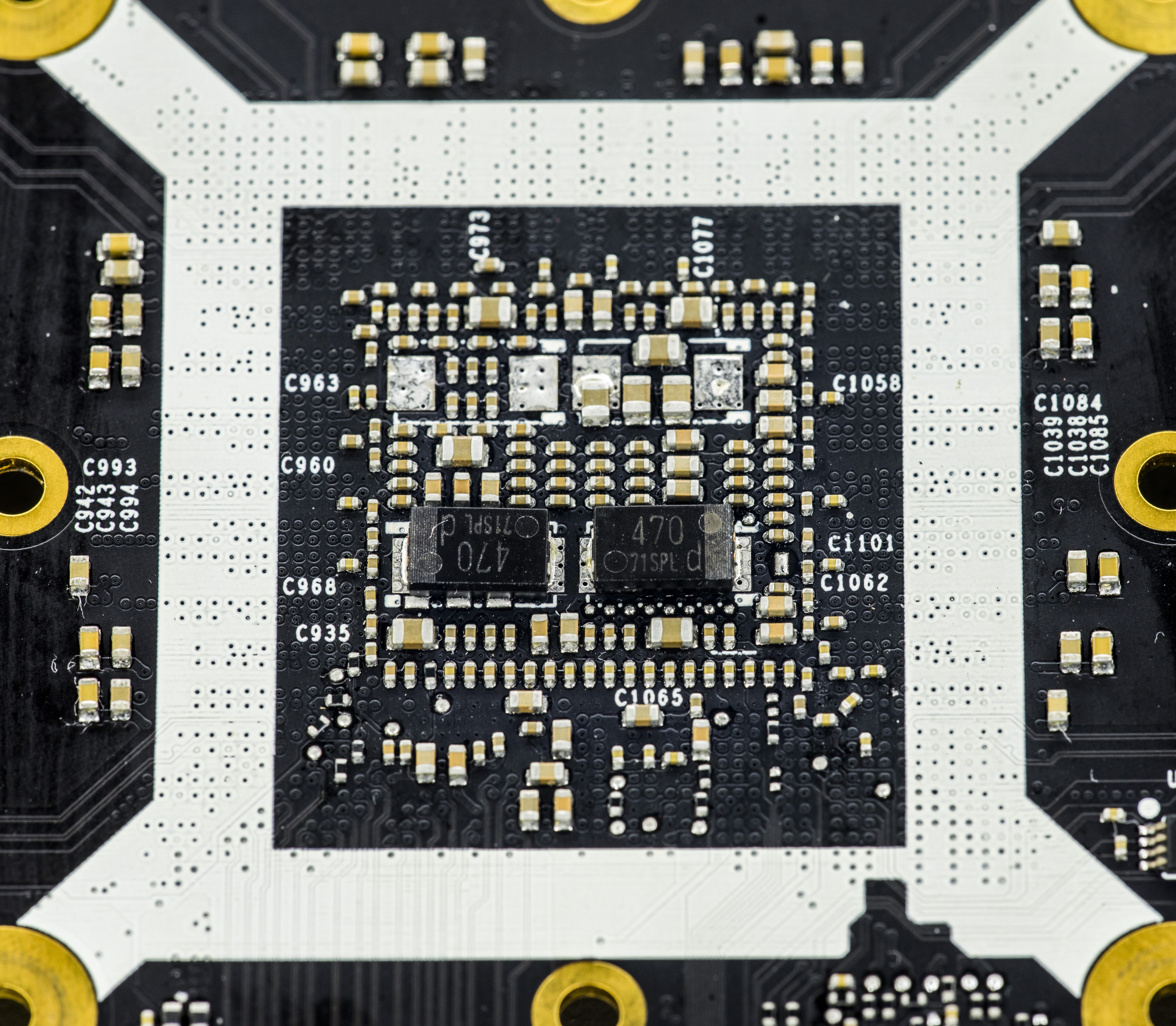
Image 20: GPU power filtering and decoupling components behind the core.
This was already covered many times on web , so we will link it in this guide too. Often owners and users are referring to 6-pin or 8-pin input power MiniFit.JR type connectors as 75W or 150W capable inputs. That is not complete truth. These power numbers are nothing but just logic programmed values for NV to determine how capable is used board hardware to deliver high power. It’s purely imaginary number and have nothing to do with actual real power rating from connector nor true power input capability. Software and NV BIOS will handle GPU clocks and reduce voltages if measured power hitting programmed BIOS limit (which can be different value than 75/150W!).
Anyone can confirm this by looking at manufacturer specification limits of power connector itself, such as Molex 26-01-3116. These are rated from 13A per contact (16AWG wire in small connector) to 8.5A/contact (18AWG thinner gauge wire).
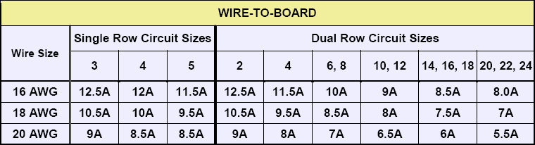
Image 21: Molex 26-01-3116 MiniFit-Jr. current rating specs.
This means that using common 18AWG cable from PSU, 6-pin connector as result specified for 17A of current (3 contacts for +12V power, 2 contacts for GND return, one contact for presence detect). Bigger 8-pin have 25.5A current specification (3 contacts for +12V power, 3 contacts for GND return and 2 contacts for detection). High end PSU usually have 16AWG wires for graphics power cable which translates info 240W or 360W power specification for 6 and 8-pin accordingly. This is given a connector temperature raise of 30 °C with all power pins used. With active airflow and decent cable quality, safe current limits are even higher.
Now if somebody states “8-pin can’t provide more than 150W”, we now know that’s not exactly correct. It is not the connector itself or cable limit the power, but active regulation of GPU/BIOS/Driver according to detection of used cables and preprogrammed limits. So how actual power measured?
This card follow standard design requirements and just like any GTX 1080 Ti have onboard Texas Instruments INA3221 power sensor IC, which is triple-channel monitor able to measure voltage, current and power on +12VDC input rails using just few external components and current shunts. Current shunt is special type of resistor which generate little, but measurable voltage which closely depends on amount of current flowing thru it. Thus card can detect power consumption in real-time and adjust its clock speed and performance automatically to keep power within specified envelope.
However KPE 1080 Ti designed in the way that does not require any additional power limit modifications or thermal protection removal mods. You don’t need to solder anything on the card to enjoy LN2 benchmarking with KPE. That is what this card is all about. It can overcome the power limit or any thermal limit with a proper BIOS. It is 100% designed to run at full LN2 speed without even touching the soldering iron.
Cards overclocked with LN2 and running 2500+ MHz, can take some serious power. Ensure that the PSU is at least 1000W and adequate for the job. Typical middle range 1200-1500W 80Plus Gold rated PSU should do the job well and we highly recommend running the system (CPU, peripherals, fans, motherboard) from one PSU and the VGA card from a separate second PSU with at least 84 A of current available on +12V rail.
If your using two power supplies make sure to turn on “VGA” power supply always first and turn off last. This is to ensure proper boot and power sequence order when using multiple PSUs. This does not matter for standard single PSU system.
To show what card consumption under extreme overclocking conditions (2550 MHz, 1.5VGPU, 1.5VMEM, -160 °C) here are some measurement results of +12V input current consumption at both of the 8-pin PCIe power plugs during 3Dmark 11 Game Test runs. Newer FireStrike and Time Spy versions of 3Dmark load graphics card bit less, so 3D11 is good example of heavy load conditions.
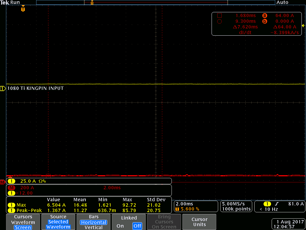
%(imgref)Image 22: Card idle at desktop, applying settings. %
Idle power during benchmark loading screen, ~6.5A taken, about 80W, 2500MHz 1.5V.
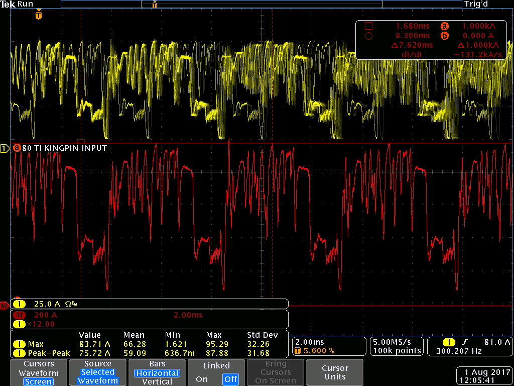
Image 23: Card started GT1 game test.
Running GT1 test, ~86A taken (1032W), max peak is 95A (1140W), 2500MHz 1.5V.
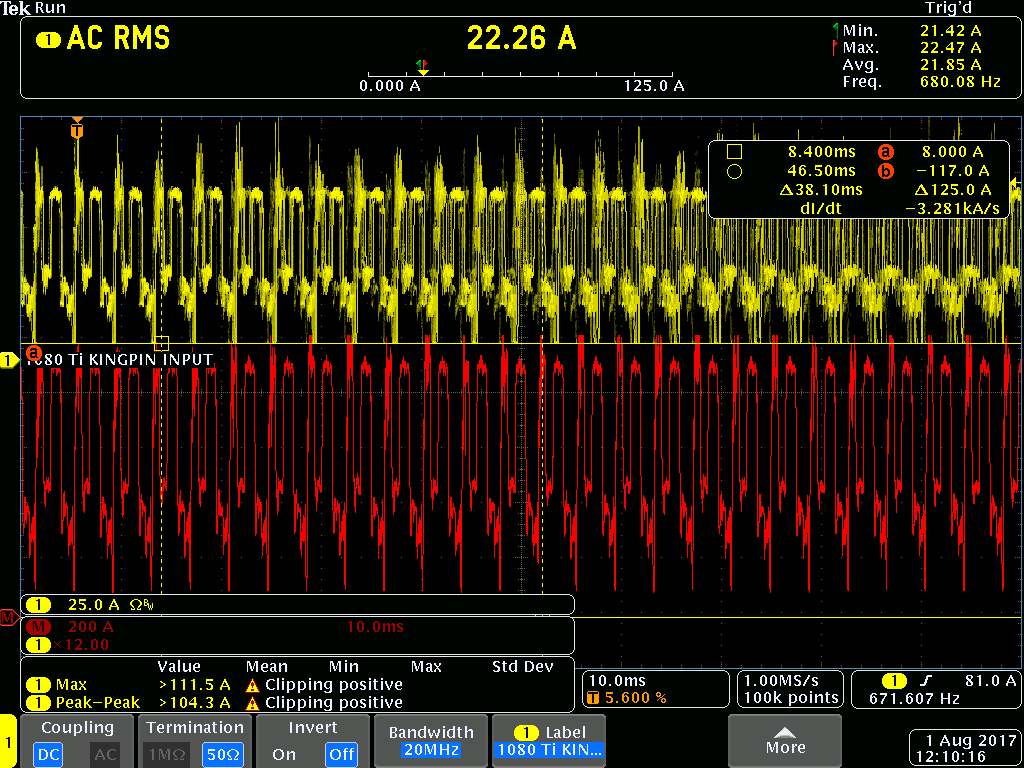
Image 24: Card finishing second run GT1.
Running GT1 test with higher clocks&voltage, ~105A (1260W), max peak is 112A (1344W!), 2600MHz 1.55V
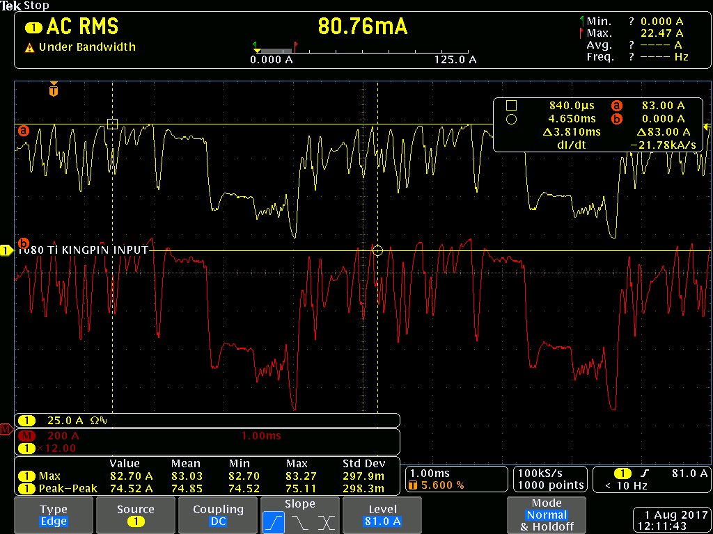
Image 25: Single shot capture, GT3 test
Running GT3 easier test, around 82A (~980W), max peak is 83A (1000W).
All results were captured with GPU cooled to -155 to -170 °C, using Tektronix MDO4054C scope and TCPA303 high-current isolated probe and it’s pre-amplifier.
With aircooling OC maximum power consumption barely hits 400W mark, peak. This should give you good understanding of extreme OC demands versus regular overclocking. That is the exact answer why high-end extreme OC graphic card have such powerful VRMs in the first place.
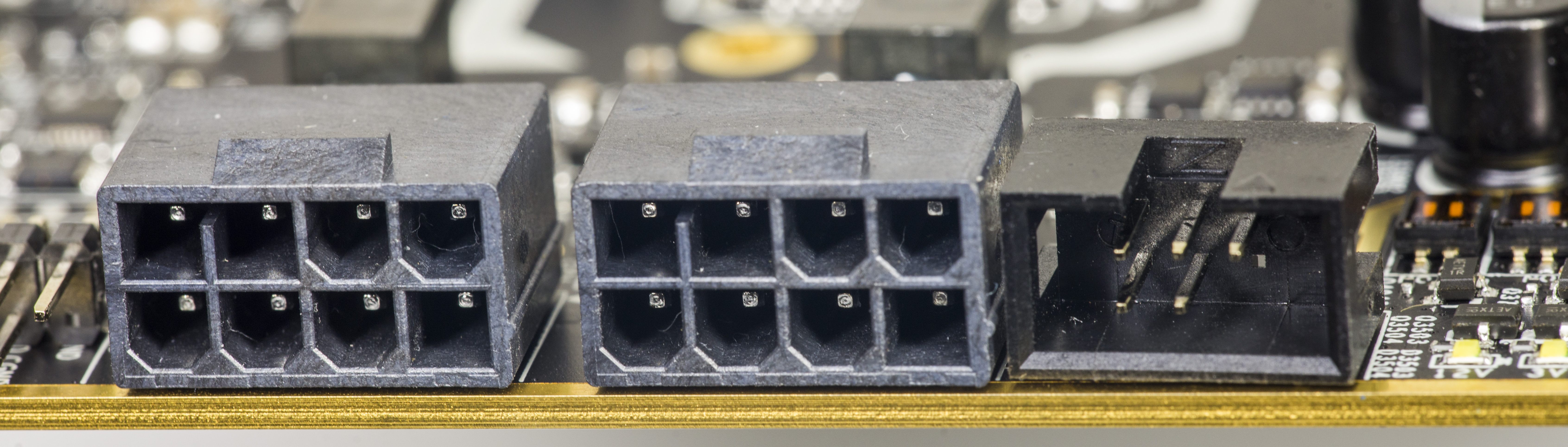
Image 26: Dual input power connectors, to support any conditions possible.
Alternative functions
If you are a first timer to the extreme world you might not have lot of experience about what hardware mods to do on your card or what traces you need to cut to disable over-temperature/over-current protections.
Again with KP cards there is no worries as you can use KPE just as it is for LN2 sessions. You only need voltage control tools which could be either EVBOT or some public SW tools such as voltage controller, or even fancy modern Raspberry Pi 3. As already mentioned, 1080 Ti KINGPIN is designed so there are no hardware modifications or soldering required to reach maximum clocks on core/mem just like all other Kingpin edition cards.
However, If you want a little more fun than just max clocks and performance, we have included a few extra tricks/mods to help you out and get even more fun from the card.
VRM design overview, available tuning and hardware controls
VRM on 1080 Ti KPE is following the legacy of it’s predecessor, 980 Ti KPE, but tuned for lower resistance and a less power hungry Pascal GP102 GPU. VRM on this card is downsized from monstrous 14+3-phase solution to more efficient 10+3 phase. It’s still well capable of delivering required power, leaving some margin even for most demanding LN2 all-out overclocking.
Little brother, 1080 Ti FTW3 also have 10-phase VRM design for GPU, but it’s very different to what KP card has to offer. Often missed by reviewers, quality and power handling ability of the phase design is what’s important, not just sheer amount of phases. It’s easy to fill in more phases, but difficult to make high-efficiency powerful per-phase design. In the end result, more efficient power design results in lower overall temperature and less heat trapped in the card. Difference can be quite significant, reaching 10-15 °C gap.
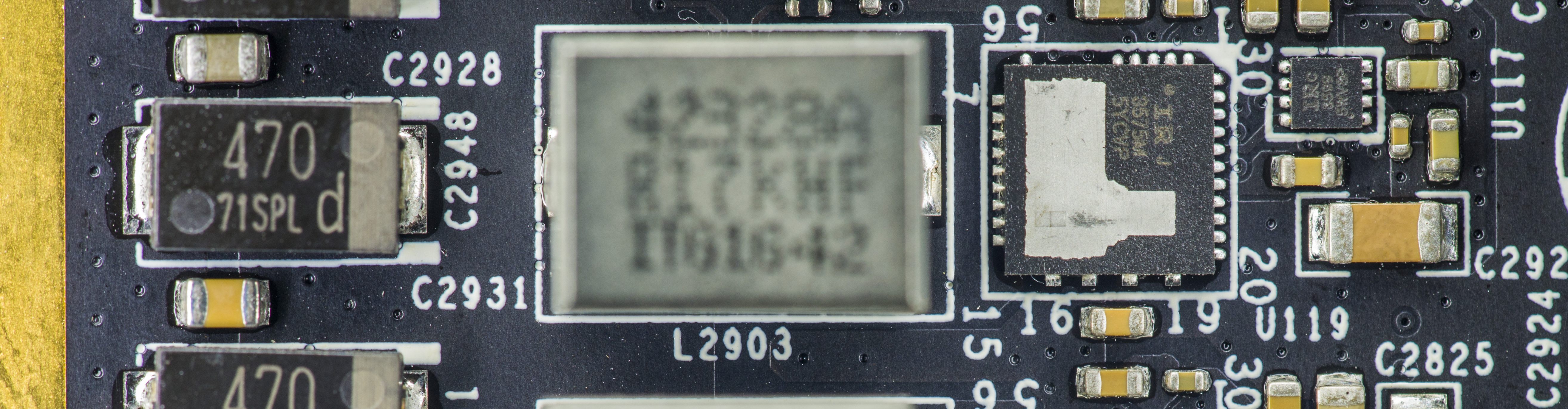
Image 27: Main power stage design with IR3575, IR3599 and high-current inductor.
- NVVDD, GPU Voltage – IR3595A digital controller with 10-phases using latest generation IR3575M PowerIRStage
- FBVDD, Memory voltage – IR3570B digital controller with 3-phases using latest generation IR3575M PowerIRStage
- PEXVDD, Digital-controlled IR 10A SupIRBuck
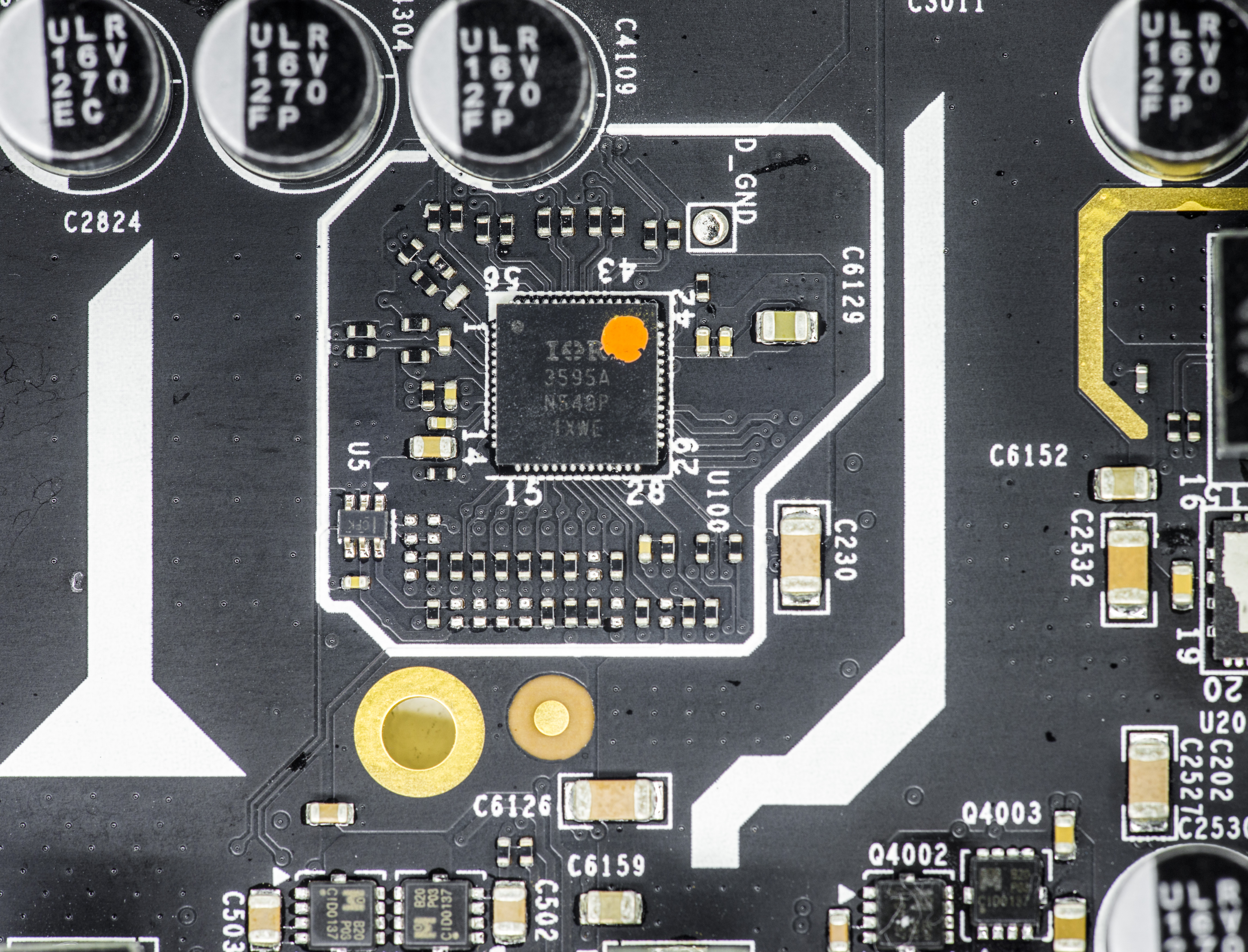
Image 28: NVVDD IR3595A main power controller
Each phase with IR3575M can deliver ~50 Amps of current with operation temperature +70 °C, or ~57 Amps with operation temperature under +50°C. And it’s unlikely for these stages to get so hot as loading is spread evenly on a larger PCBA area across all phases.
Traditional power IC have plastic epoxy package, which is not a great thermal conductor. Even with added heatsink, temperatures inside the package are not improved much. 70-80% of the heat flow into copper pads and PCB layers as a result. To resolve this design aspect, 1080 Ti KPE use special exposed metal tops IR3575M power stage IC. This allow heat to be dissipated not just thru PCBA copper layers, but also directly to VRM heat-sink plate. It helps to keep VRM significantly cooler and waste less power, improving margins on power target limit used by NVIDIA Boost function.
If you want to use non-stock VRM heatsink plate, make sure you install protective mylar over the top surface of power stage ICs, as top exposed metal pad is connected to output power node. You don’t want to short these ICs to ground thru the metal heatsink.
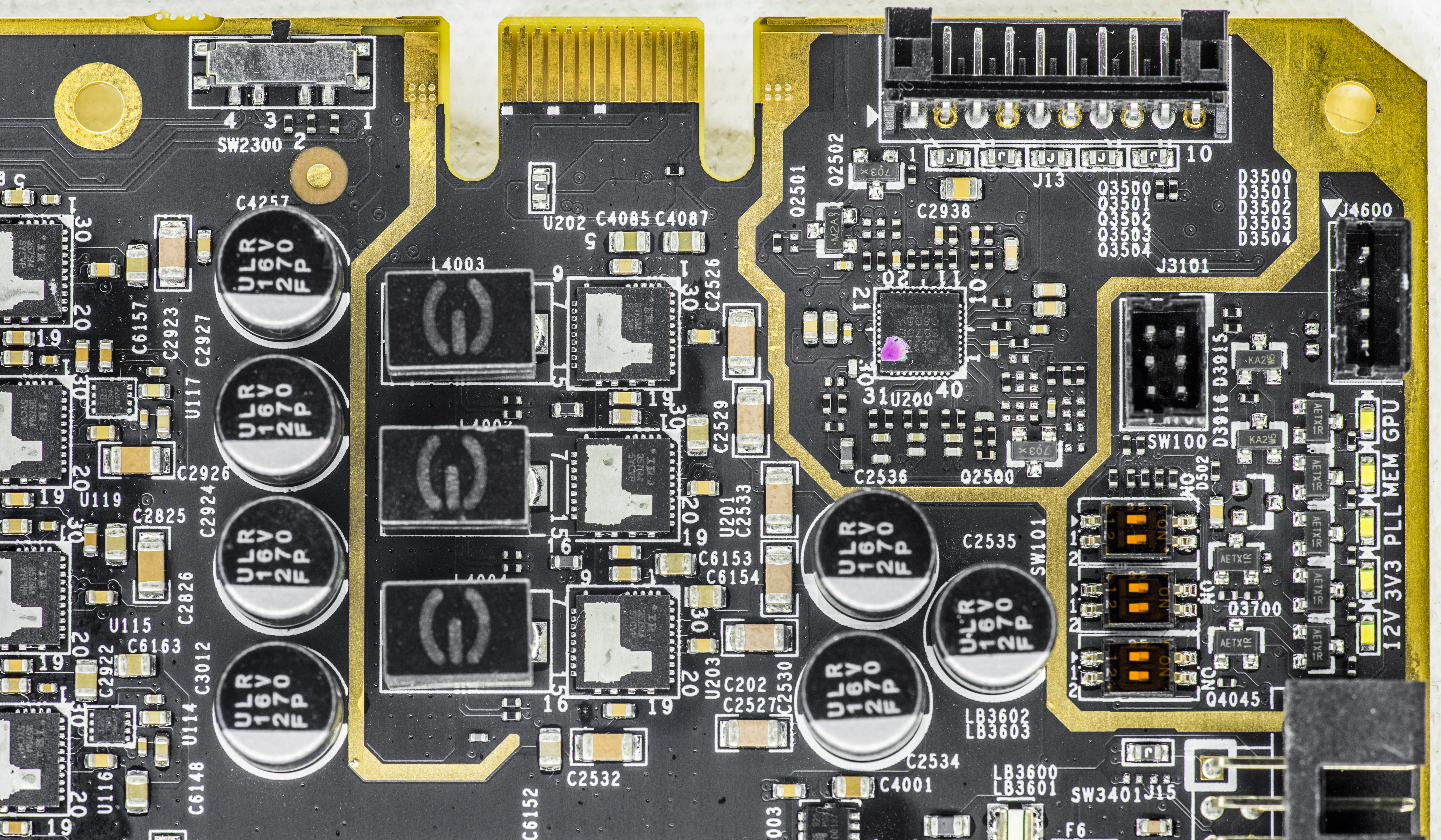
Image 29: 3-phase memory controller in input +12V capacitors
There is rather accurate VRM overview from Gamers Nexus covering the vrm components used on KPE in good detail. It is worth to watch if you have a spare 30 minutes.
For voltage monitoring purposes this card has traditional EVGA ProbeIt, which is a 10-pin 2mm pitch PH-type connector near the top PCB edge. Pin definition as below:
| Pin 1 | GPU voltage | 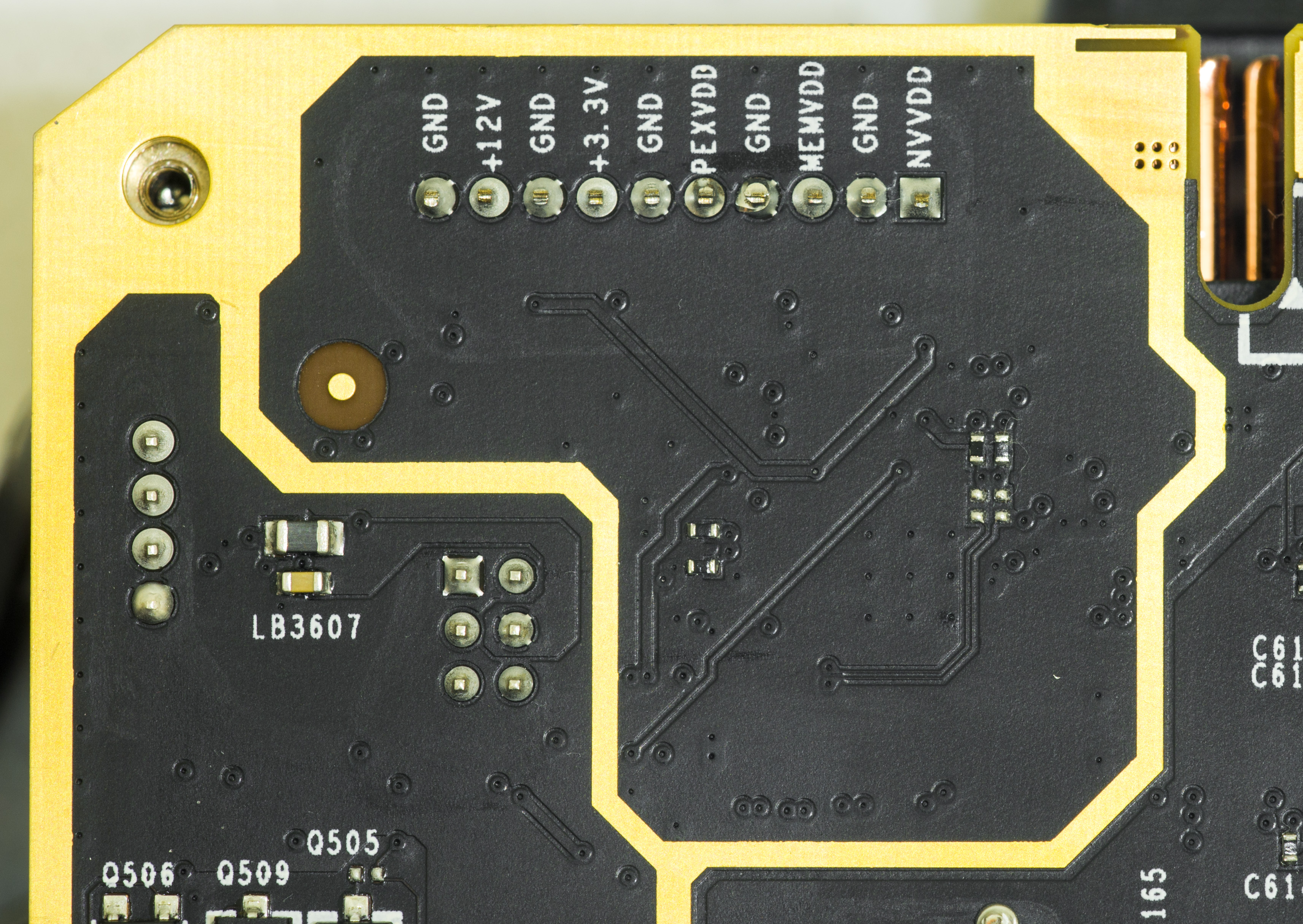 |
| Pin 2 | Ground | |
| Pin 3 | MEM voltage | |
| Pin 4 | Ground | |
| Pin 5 | PLL voltage | |
| Pin 6 | Ground | |
| Pin 7 | Onboard +3.3V power voltage | |
| Pin 8 | Ground | |
| Pin 9 | Onboard +12V PCIe power voltage | |
| Pin 10 | Ground |
Table 5: ProbeIt measurement port pinout definition
This pinout is same since the GTX 680 era, so you still can use your ProbeIt setup if you had it done before. Also some helpful labels are located on the bottom side of PCB near each connector pin to aid connection.
You can use bundled ProbeIt adapter to your usual multimeter probes, or in case you want to have custom cable connection to your specific meter, you can grab connector separately for example here from Digikey.com . You will also need these contacts. If you want less pins (for example only 4 to monitor GPU and MEM voltage) you can get needed housings right here .
In addition to monitoring, 1080 Ti KINGPIN card again provide a few more extra HW controls covered in next section.
V-Tune on-board switches
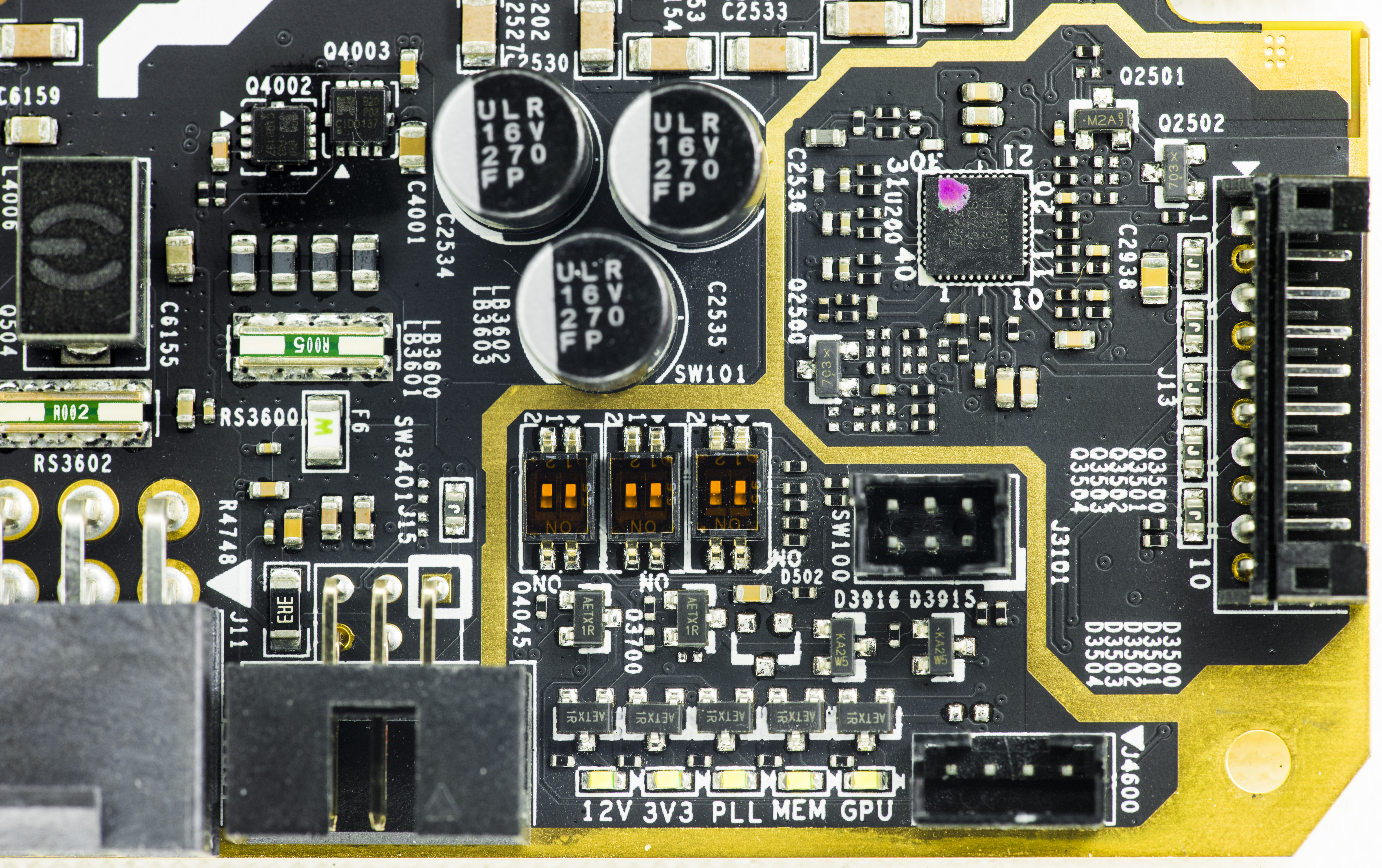
Image 30: XOC corner with RGB LED headers and miniature switches.
Card equipped with three dual-position switches near the EVBOT connector. Left to right they are labelled SW3401, SW101 and SW100. Factory default setting for all switches is OFF. Status and function map for all these presented in table below
| Function | SW3401 Pos.2 | SW3401 Pos.1 | SW101 Pos.2 | SW101 Pos.1 | SW100 Pos.2 | SW100 Pos.1 |
|---|---|---|---|---|---|---|
| Factory default setting | OFF | OFF | OFF | OFF | OFF | OFF |
| VGPU +25mV increase | ON | OFF | OFF | OFF | OFF | OFF |
| VGPU +50mV increase | ON | ON | OFF | OFF | OFF | OFF |
| VGPU Droop setting 1 | OFF | OFF | ON | OFF | OFF | OFF |
| VGPU Droop setting 2 | OFF | OFF | OFF | ON | OFF | OFF |
| VGPU Droop setting 3 | OFF | OFF | ON | ON | OFF | OFF |
| VMEM Droop setting 1 | OFF | OFF | OFF | OFF | ON | OFF |
| VMEM Droop setting 2 | OFF | OFF | OFF | OFF | OFF | ON |
| VMEM Droop setting 3 | OFF | OFF | OFF | OFF | ON | ON |
Table 6: V-Tune switch definitions
Switch positions are listed in table with same order as photo orientation above. Different switch functions can also be used in conjunction.
Voltage increase method is bit different to software or EVBOT override control as an offset is applied at any time even if the GPU uses the native mechanism to control voltage. It could be useful if you wanted little bit extra voltage for everyday gaming without any use of EVBOT or other voltage override tinkering. Each offset SW3401 switch position at ON will add +25 mV, so both will give +50 mV.
Five white LEDs near the PCBA edge allow to monitor the voltage health in realtime. Their definition and function is same as older Classified/KINGPIN cards. If any of the LEDs not on, the voltage rail is absent and system/card require troubleshooting.
EVBOT way to tweak real-time settings
For lucky people who still have EVBOT controller, there is EVBOT Firmware for EVGA GeForce GTX 1080 Ti KPE, Rev.63
You can update your EVBOT with EVBOT Flash tool supporting Kepler & Maxwell & Pascal GPU
EVBOT Firmware update procedure listed below:
- Connect the EVBot cable to the MB port located on the EVBot device.
- Connect the other end of the EVBot cable to your graphics card EVBOT port.
- Run EVBotFlashTool.exe on your Windows PC. Make sure VGA card is working normally and have driver installed.
- Select the firmware 1080i63.hex for flashing.
- Hold down the EVBot POWER button for 7 seconds until you see the EVBot screen display FLASH MODE.
- Click OK in EVBot Flash Tool to being the flashing process.
- After flash is complete, unplug EVBot, then plug it back in to any EVBot port.
This can be done using one of next VGA cards:
- EVGA GeForce GTX 285 Classified
- EVGA GeForce GTX 580 Classified
- EVGA GeForce GTX 680 Classified
- EVGA GeForce GTX 770 Classified
- EVGA GeForce GTX 780 Classified
- EVGA GeForce GTX 780 Ti Classified (both normal and KINGPIN)
- EVGA GeForce GTX 980 Classified (both normal and KINGPIN)
- EVGA GeForce GTX 980 Ti Classified (both normal and KINGPIN)
- EVGA GeForce GTX 1080 Classified
- EVGA GeForce GTX 1080 Ti KINGPIN
EVBOT with i63 firmware allow you to control the following settings:
| NVVDD | GPU Voltage, range is from 800 to 1850 mV |
| NVVDD Vdroop | Leave disabled |
| NVOCP | OCP protection for LN2 benching, can be enabled or disabled |
| NVOC Mode | Should be set Extreme for LN2 benching, can be Normal or Extreme |
| NVPWM | Sets PWM frequency for GPU VRM, from 750kHz to 1333kHz |
| FBVDD | Memory voltage, from 1500 to 2100mV. Best for LN2 around 1400-1550mV |
| PEXVDD | PCIe PLL voltage, from 1045mV to 1400mV |
Table 7: Available EVBOT menu items
This is it, these settings and ranges are more than enough to max out GP102 GPU, even on LN2 cooling. EVBOT also supports profiles for quick save/load off all settings. Any of available four channels can be used for card connection.
Software way to tweak settings
FTW12345’s little tool also working on this KPE, as it’s using same controllers architecture as previous 980 Ti KINGPIN card.

Image 31: VRM controller tool
There is one drawback for software as settings can be adjusted any time and will keep till the power cycle (card power turn off/turn on). So if your motherboard have a shutdown then all voltages and OCP settings will be reset to default. You must reapply everything again to revert to previous state.
That’s one of the reasons why other ways can be better like EVBOT/RPI or any hardware mod are a preferable tool for hardcore LN2 benching. The power settings can be on stand-by and applied right away, without repetitive fiddling with controls on each power cycle.
Raspberry Pi way to control settings
You can use the widely available Raspberry Pi $40 USD single-board Linux computer to set voltages via EVBOT port on the card.
Raspberry Pi can be best overclocker’s friend, and thanks to easy access to onboard SPI, I2C, WiFi and LAN interfaces can be used for many things, including memory SPD DIMM programming, hardware monitoring and voltage controls.
In case of EVGA 1080 Ti KP, you will need to connect just three wires from the Raspberry Pi to the VGA’s EVBOT connector.
EVBOT Pinout and connection map is shown in table below:
| Raspberry Pi signal name | Raspberry Pi Pin | EVBOT Pin |
|---|---|---|
| Ground | Pin 9 on header P1 | Pin 6 on header J3501 |
| I2C Data, SDA | Pin 3 on header P1 | Pin 5 on header J3501 |
| I2C Clock, SCL | Pin 5 on header P1 | Pin 3 on header J3501 |
Table 8: Cable pinout definition
EVBOT Pinout is next (looking at connector’s face):
| Pin 1 | |
| Pin 3 SCL | Pin 4 |
| Pin 5 SDA | Pin 6 GND |
Table 9: EVBOT pinout looking at the connector. Power connector at bottom side
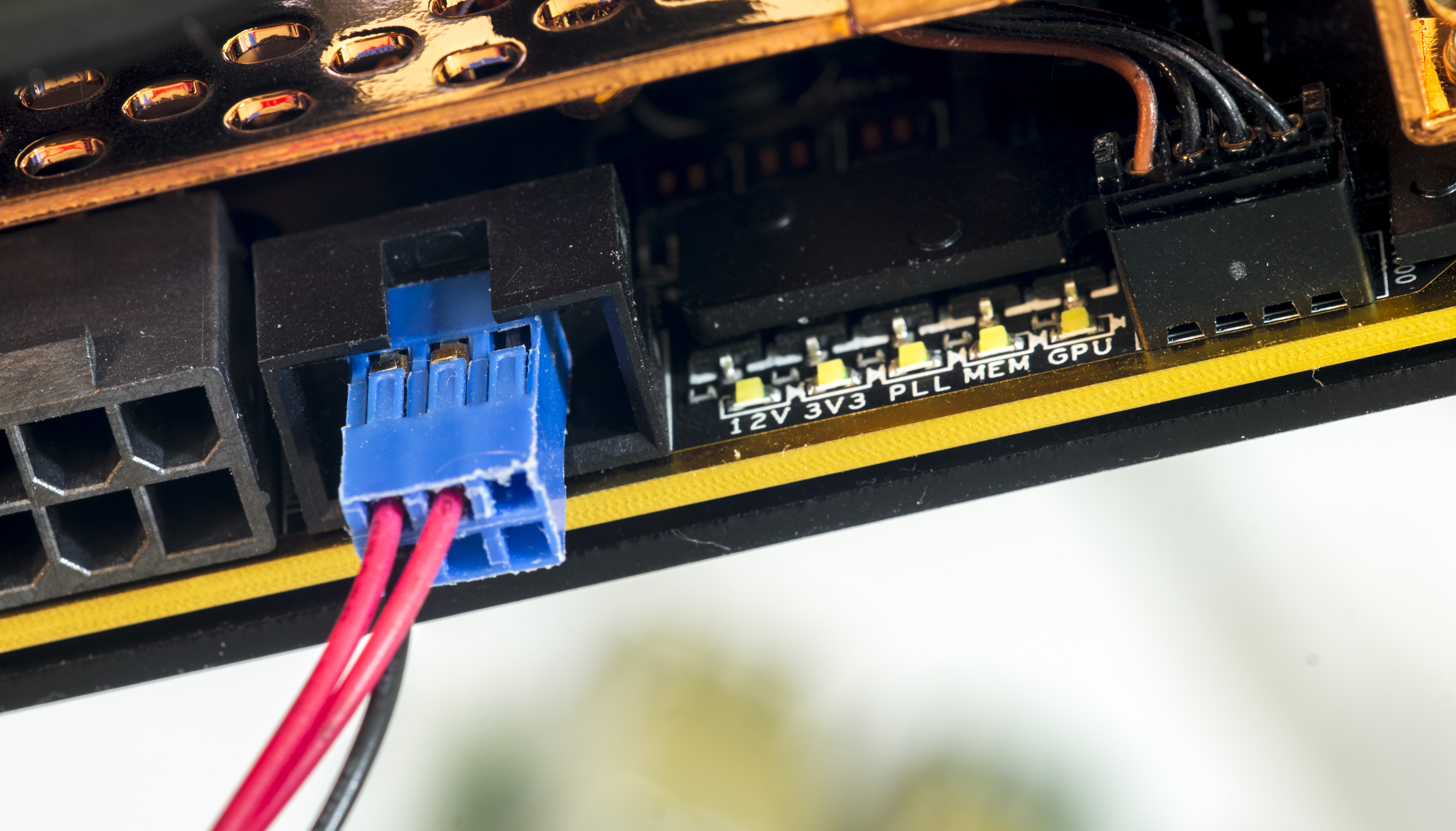
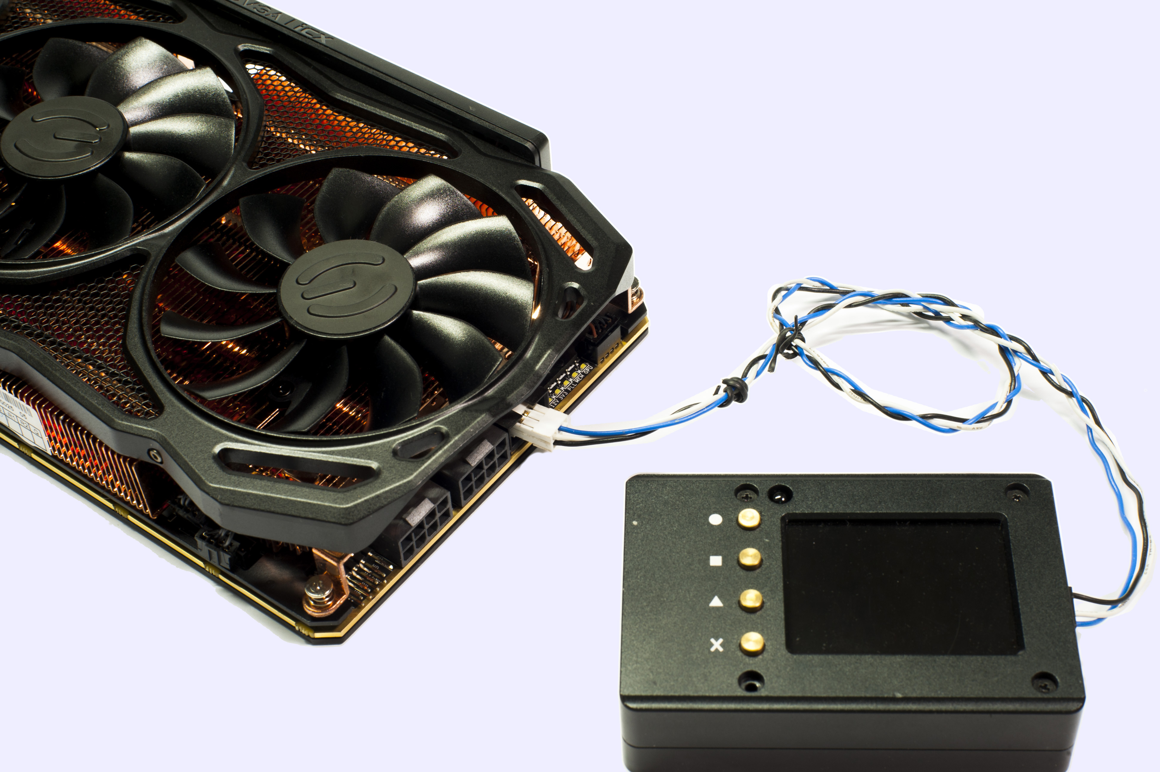
Image 32: Connection between VGA card and Raspberry Pi 3 SBC
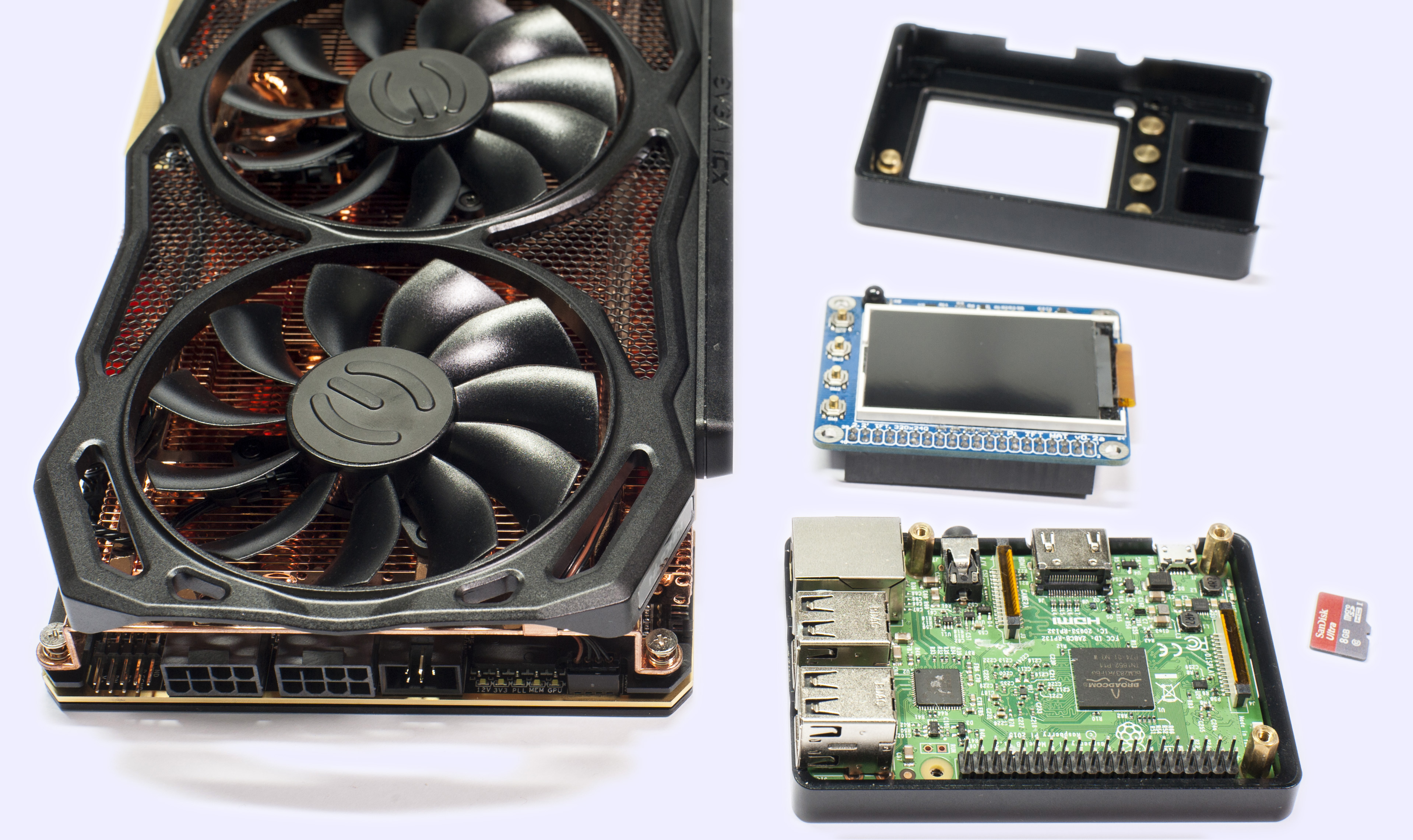
%(imgref)Image 33-34: RPI3 with case and 2.2 inch 320×240 TFT LCD
Now you can power everything on, and connect to Raspberry Pi terminal.
Download next tool and put into Pi’s disk storage.
ELF-executable for Raspberry Pi Linux [using I2C1 port]
ELF-executable for Raspberry Pi Linux [using I2C0 port]
This little voltage setting tool was compiled and tested on Raspberry Pi B v2.0, running wheezy image.
After connection has been made, check that all pins are correct and try to detect card on RPI.
root@raspberry-pi:~# i2cdetect -y 1
     0  1  2  3  4  5  6  7  8  9  a  b  c  d  e  f
00:          -- -- -- -- -- 08 -- 0a -- -- -- -- --
10: -- -- -- -- -- -- -- -- -- -- -- -- -- -- -- --
20: -- -- -- -- -- -- -- -- -- -- 2a -- -- -- -- --
30: -- 31 -- -- 34 -- -- -- -- -- -- -- -- -- -- --
40: -- -- -- -- -- -- -- -- -- -- -- -- -- -- -- --
50: -- -- -- -- -- -- -- -- -- -- -- -- -- -- -- --
60: -- -- -- -- -- -- -- -- -- -- -- -- -- -- -- --
70: -- -- 72 -- -- -- -- --
Correct output is shown on terminal capture above.
Now you can run download tool here to your Pi and run it to set GPU voltage.
root@raspberry-pi:/home# ./ptikpe_vcore
/******** Manual VID setting tool :) **********/
Voltage monitored = 1000 mV
 Enter voltage, in millivolts (800...1850): 1000
Voltage monitored = 1000 mV
 Enter voltage, in millivolts (800...1850): 1100
Voltage monitored = 1100 mV
 Enter voltage, in millivolts (800...1850): 1200
Voltage monitored = 1197 mV
 Enter voltage, in millivolts (800...1850): 1300
Voltage monitored = 1293 mV
 Enter voltage, in millivolts (800...1850): 1400
Voltage monitored = 1388 mV
 Enter voltage, in millivolts (800...1850): 0
Incorrect voltage input!
Here voltages in 100mV steps were entered and actual readout values for input & output voltage after each change also reported back.
DIY RGB lights for waterblock setup or casemodding
To connect LEDs, use the same connector type as ProbeIt , but with 4-pins only. This connector for RGB LEDs J4600 is located on top right corner of the board.
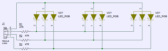
Image 35: DIY RGB LED connection schematics for connector J4600
Any typical common anode RGB LED will work fine. SMT example of generic 5050 RGB LED is used on schematic above. By attaching LEDs, you can use Precision XOC to adjust LED color, brightness and mode settings.
Here’s example how this mod worked on EVGA GeForce GTX 980 Ti KINGPIN card.
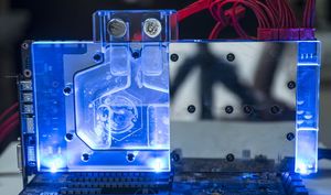
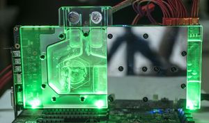
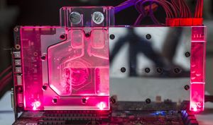
Image 36-38: Modified waterblock with attached RGB Backlight.
Summary
Happy benching and gaming! If you have any comments or question, join us in comment section at the right side of this article or discuss at EVGA OC Forum.
Feel free to share and link to this guide, but keep links and all references intact, as this guide will be updated in future.
© Vince “K|NGP|N” Lucido & Illya “TiN” Tsemenko
Modified: March 25, 2020, 9:22 p.m.