Construction and design
Counter built in nice and rugged cast enclosure. It rather compact for full-size 19” instrument.
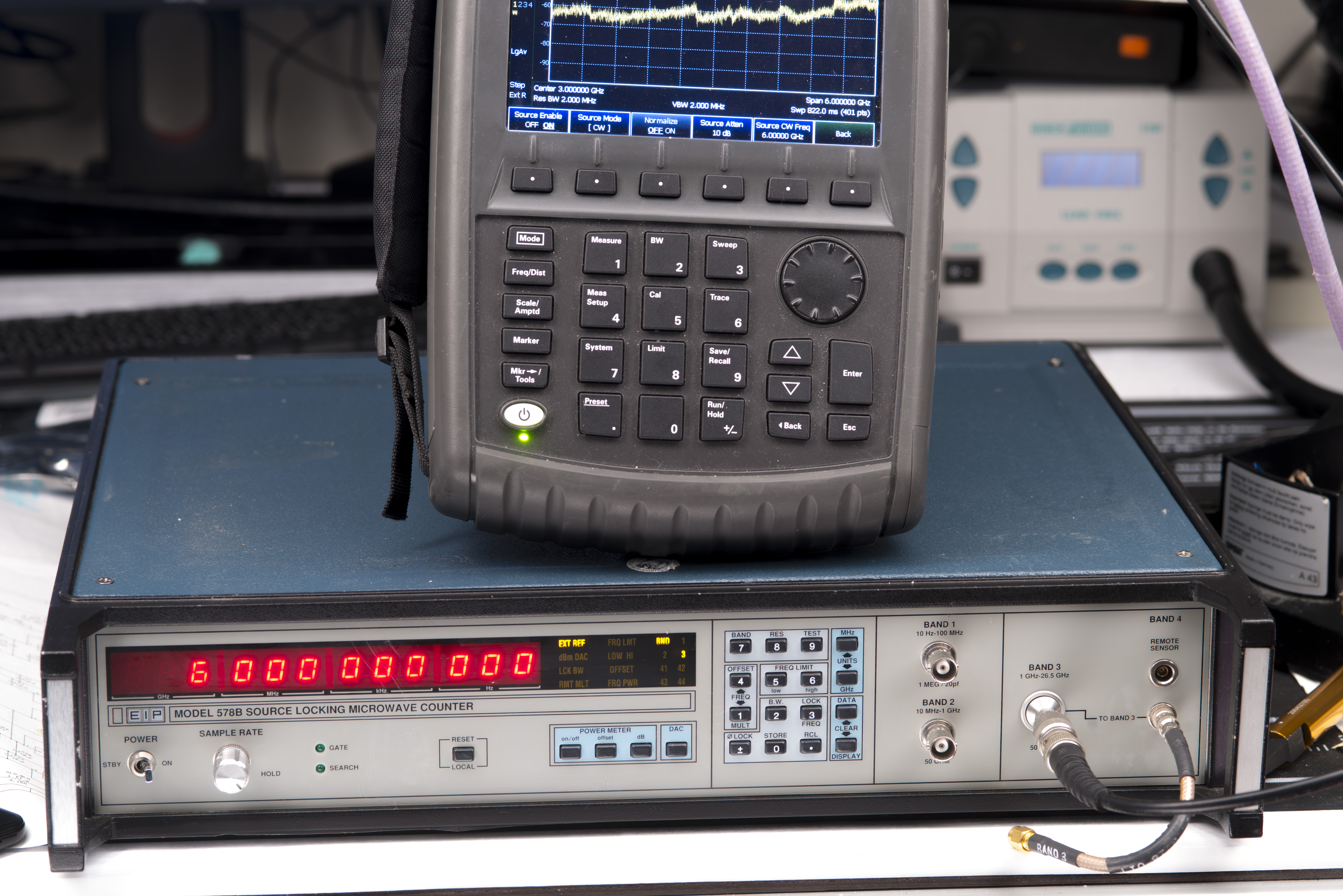
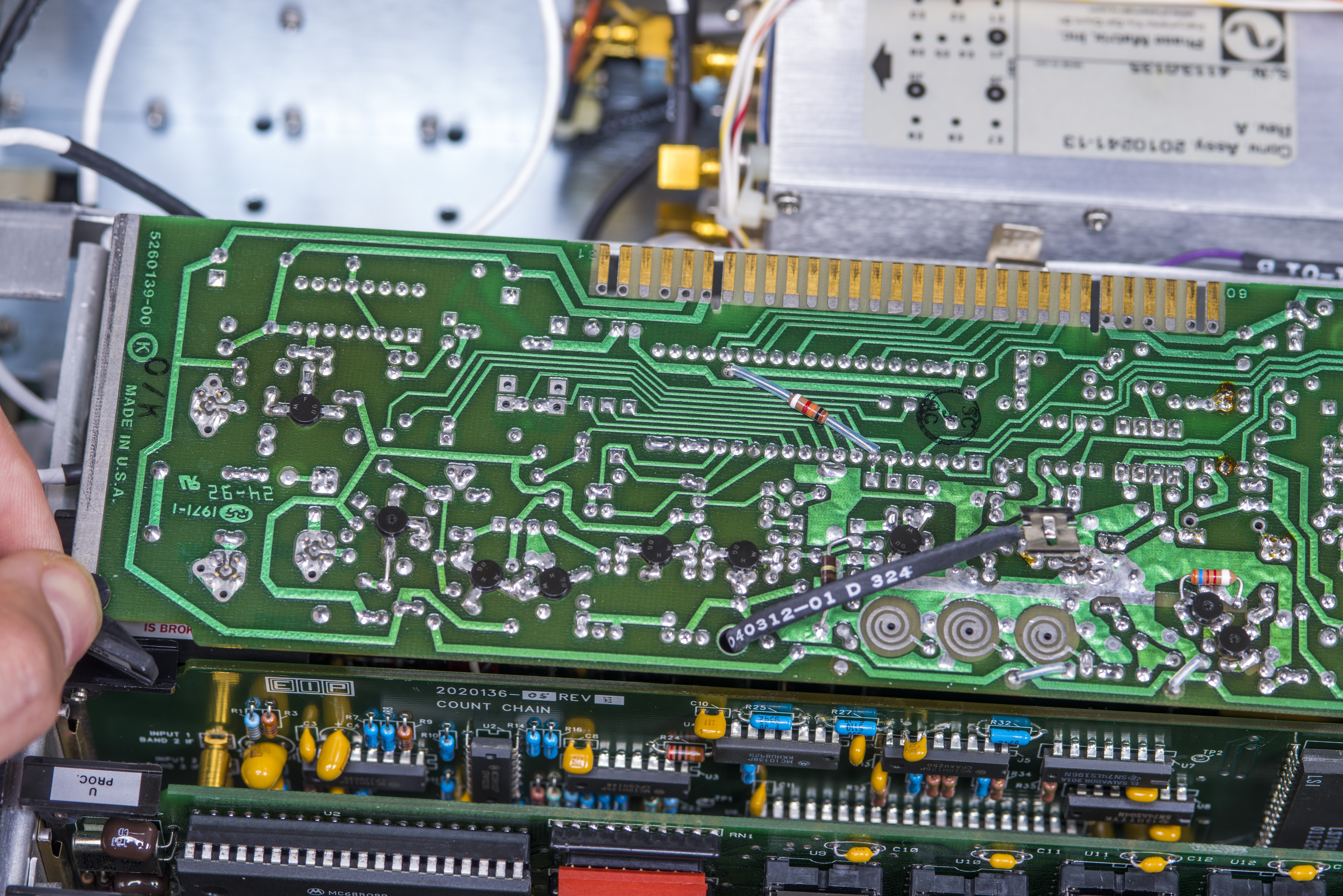
Image 1: EIP 578B measuring 6 GHz sine, sourced by Keysight N9912A analyzer
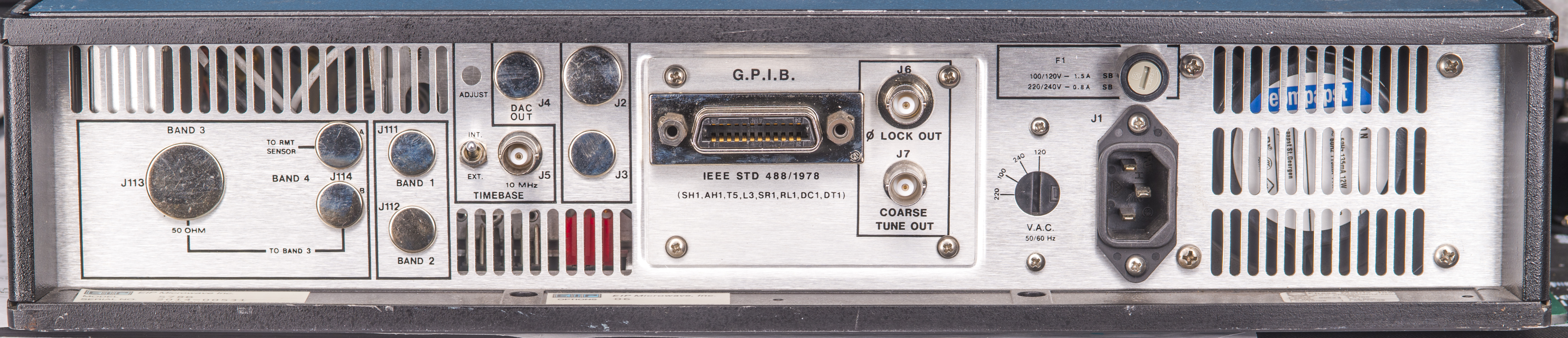
Rear have optional input ports for automated applications, external timebase BNC input (accepts 10 MHz), GPIB interface for communications, phase-lock output and coarse tune output for external source operation. There is rotary switch for mains voltage and fan vent slots.
Instrument have four separate inputs for specific frequency bands:
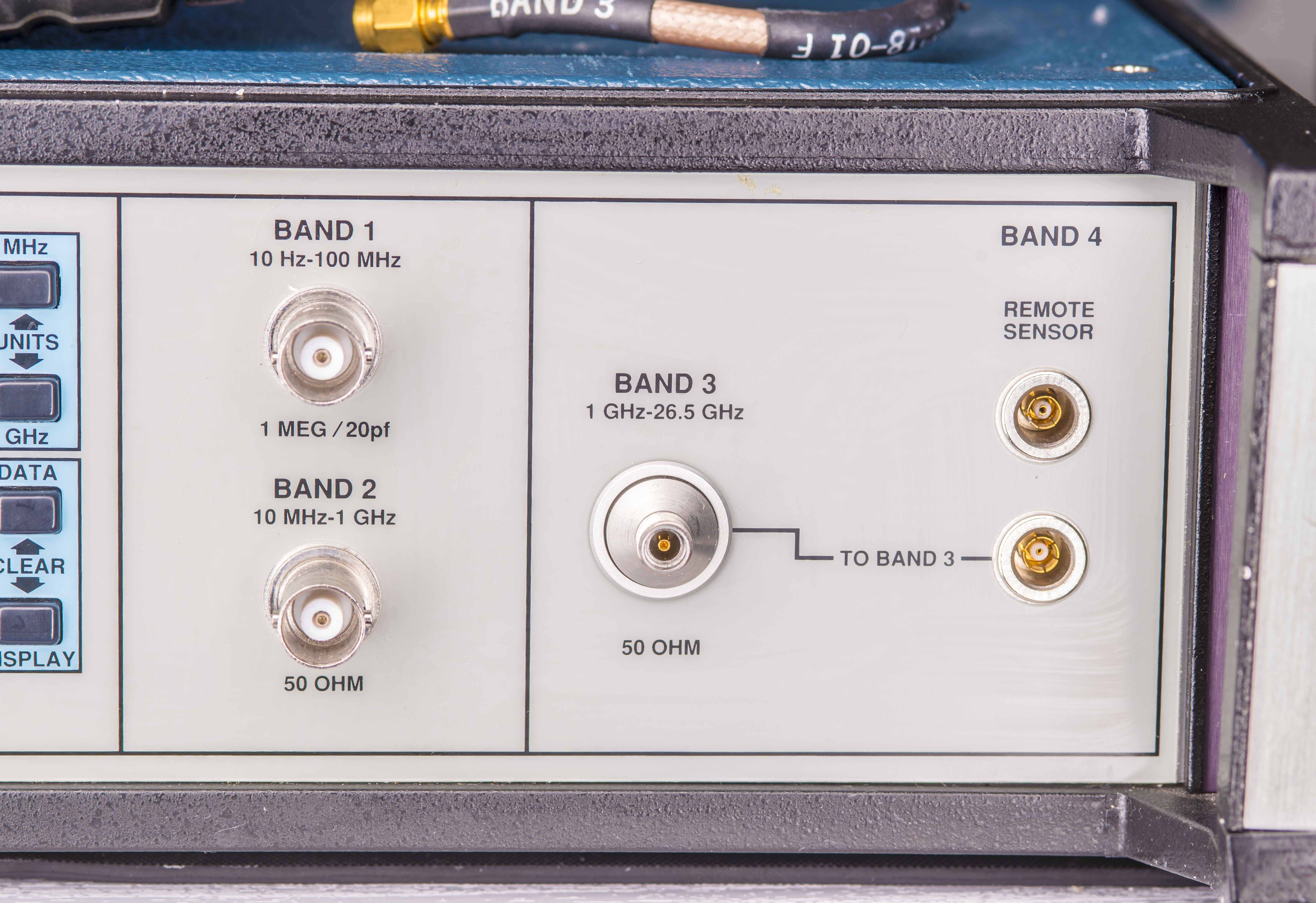
- Band 1 , 10 Hz to 100 MHz with 1 MΩ impedance | 20 pF load, resolution up to 0.1 Hz
- Band 2 , 100 MHz to 1 GHz with 50 Ω impedance, resolution up to 1 Hz
- Band 3 , 1 GHz to 26.7 GHz with 50 Ω impedance, resolution up to 1 Hz
- Band 4 , 26.7 GHz to 110 GHz with external mixer hardware, resolution up to 1 Hz
Input connector types are BNC for Band 1 and 2, precision 3.5 mm (Type K) for Band 3.
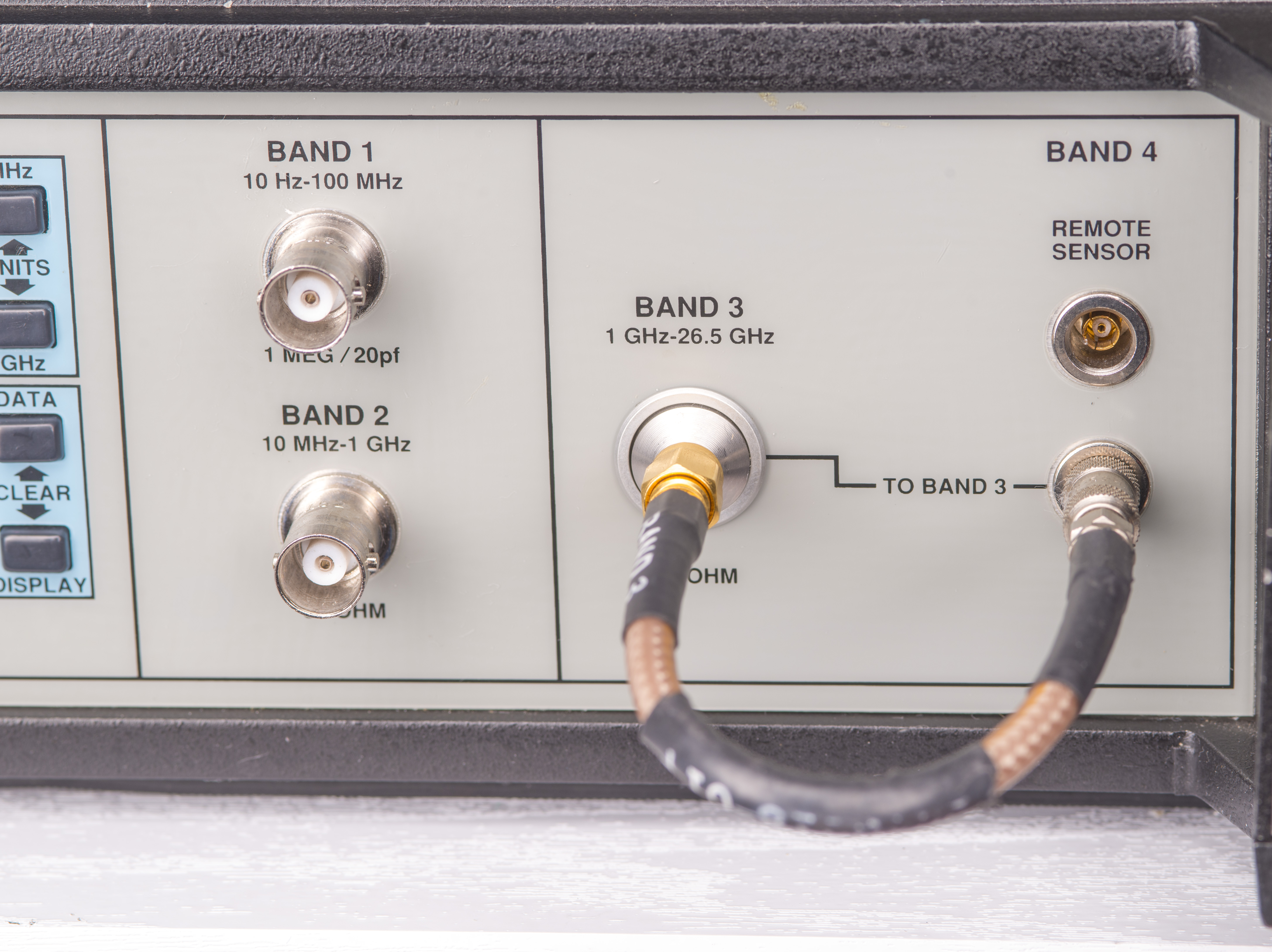
Band 4 is optional and available only with 578B option 06, which is our unit.
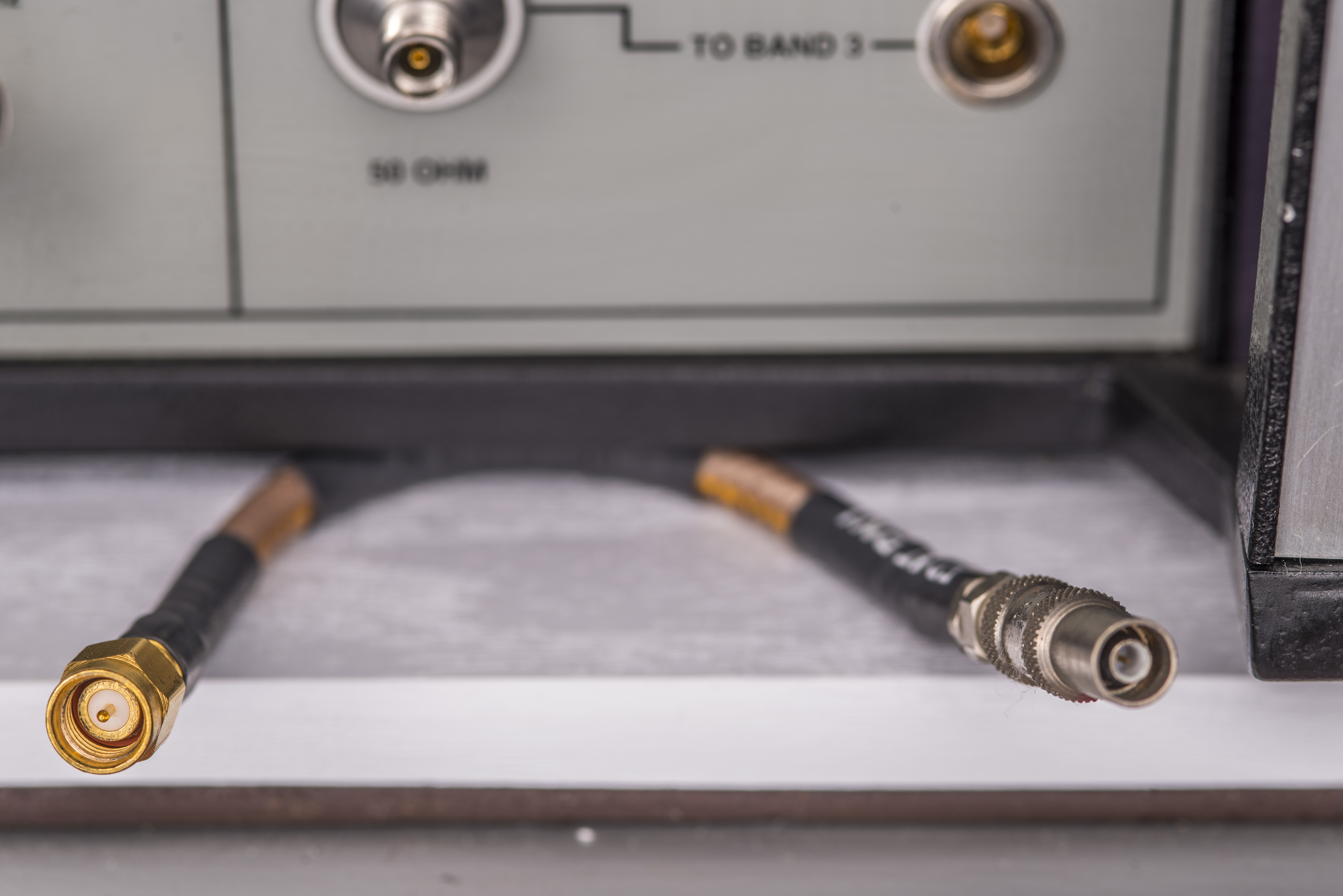
Band 3 and Band 4 connected together with special short jumper.

What is this connector type? It has push-pull locking mechanism.
Manuals
PhaseMatrix / EIP 575B and 578B Brochure
PhaseMatrix / EIP 575B and 578B Datasheet
PhaseMatrix / EIP 575B and 578B Instruction Manual
PhaseMatrix / EIP 545B Service Manual
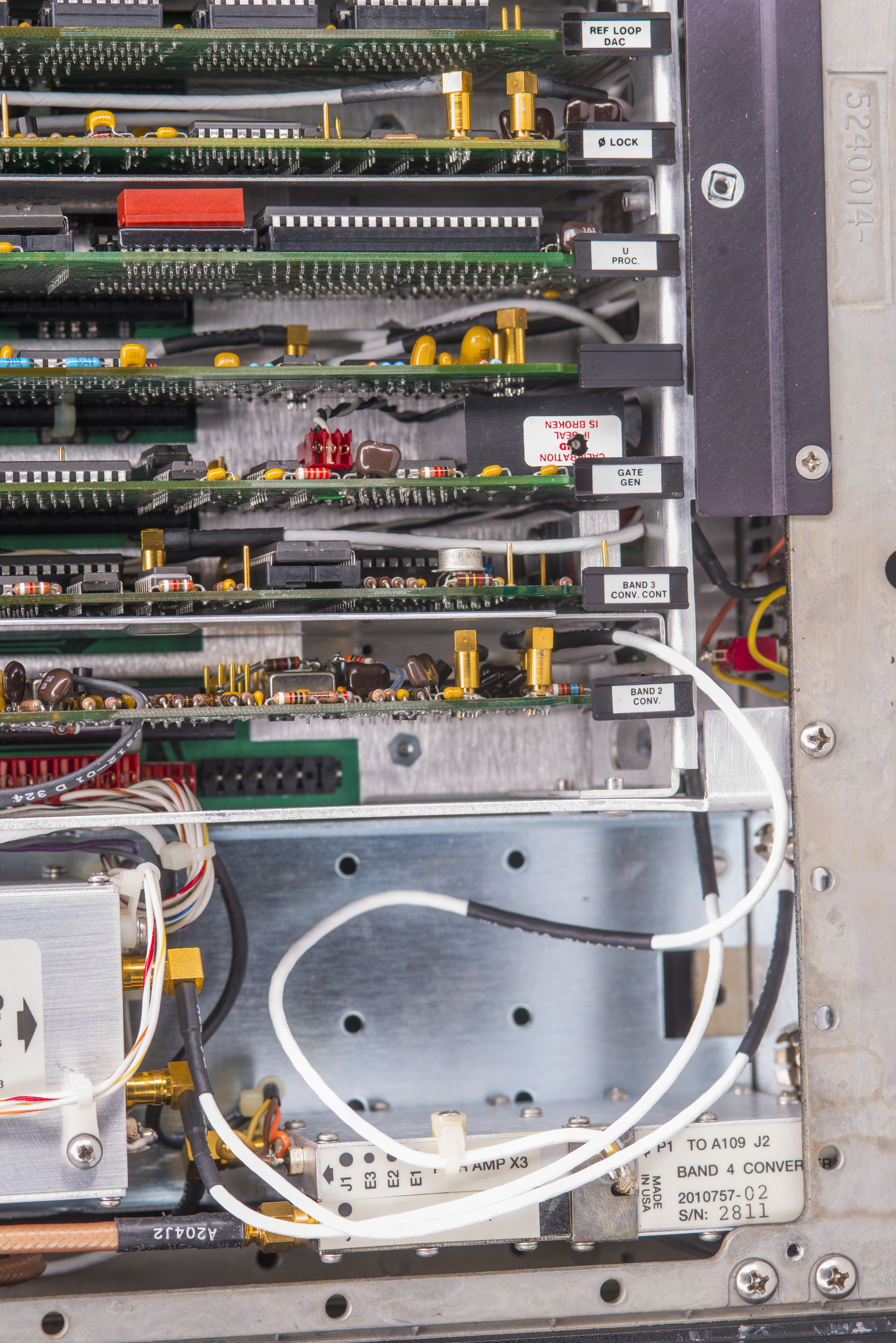
Teardown
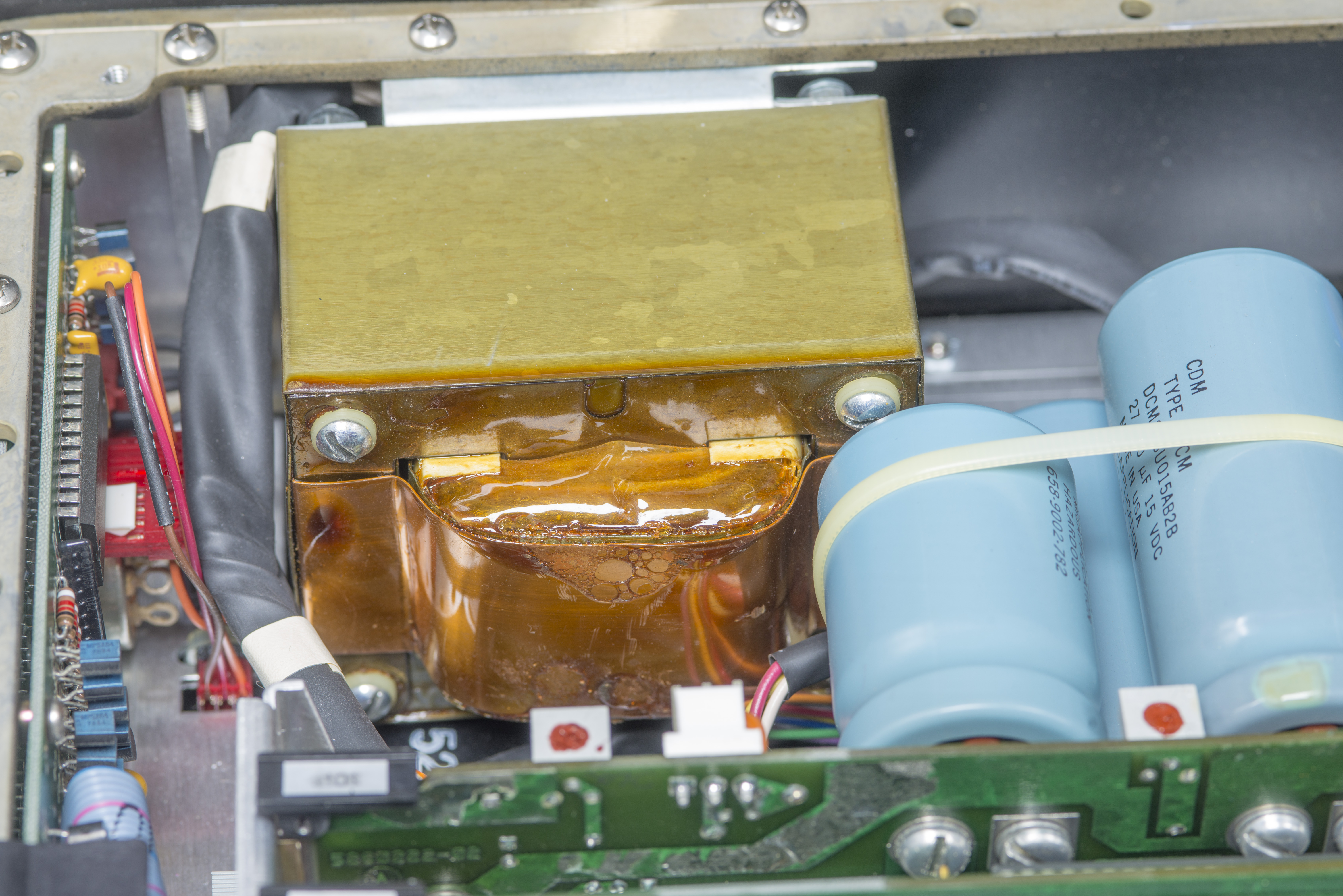
Unit was almost pristine clean inside.
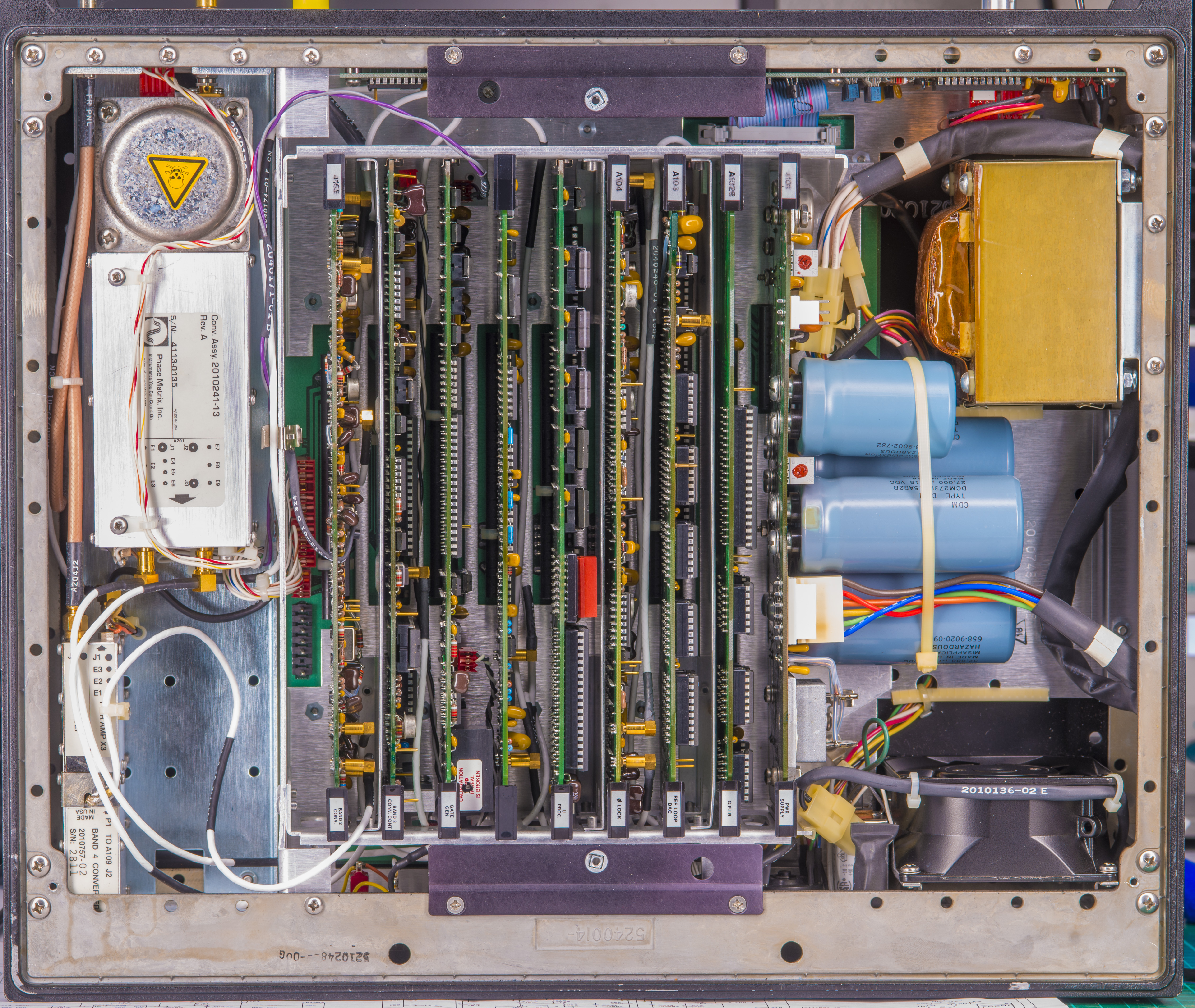
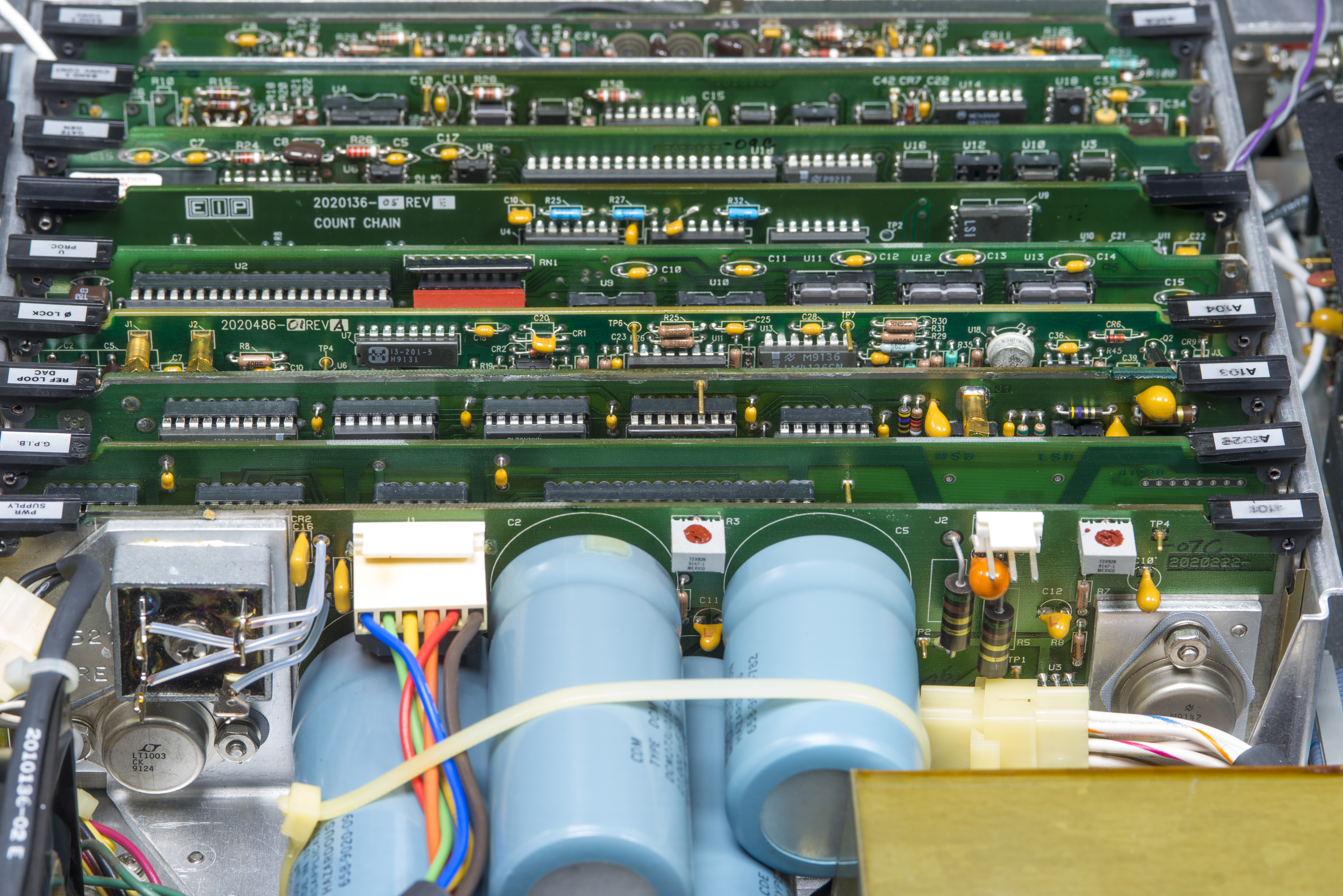
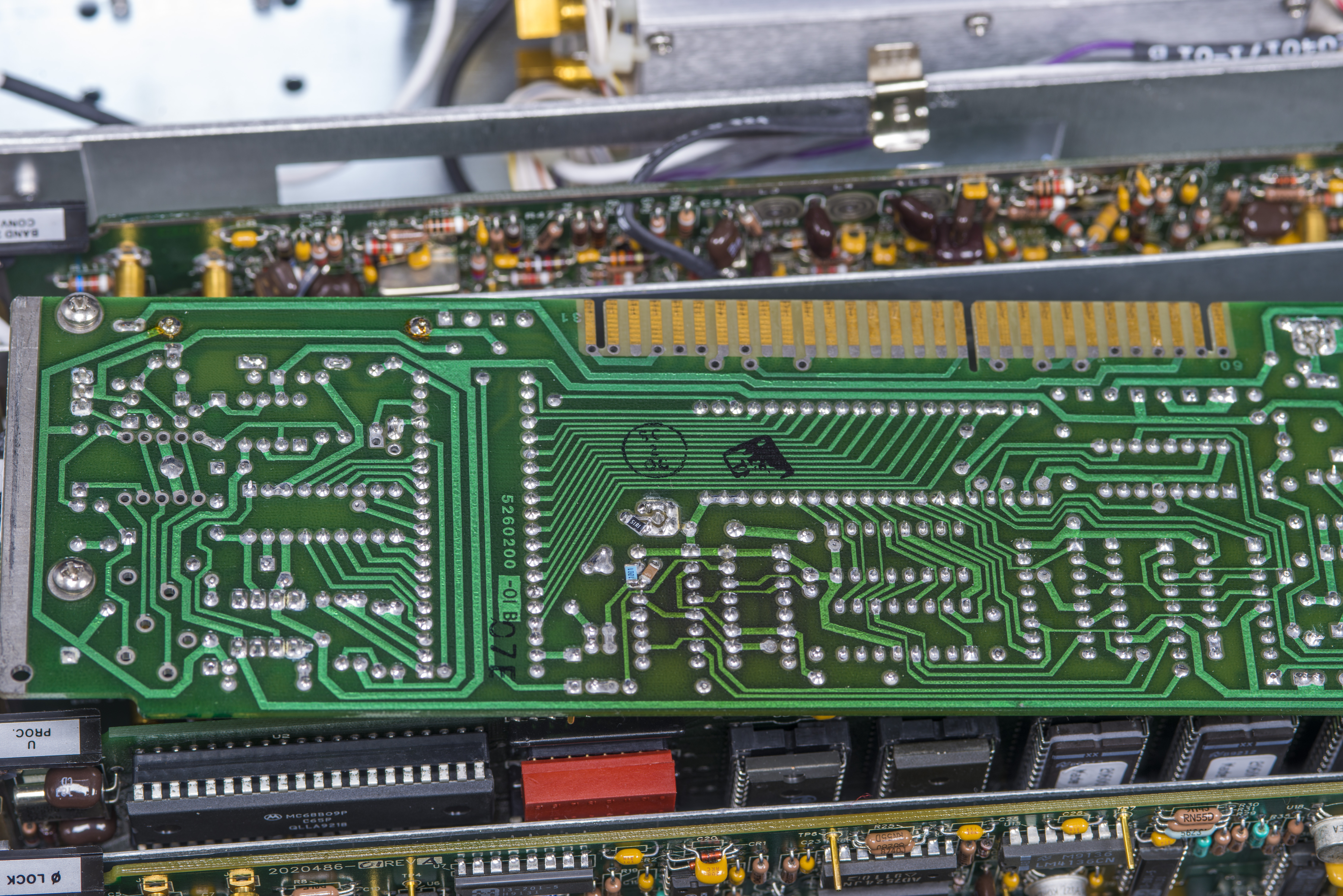
Design is easy to service with modular design, with functionally separate cards.
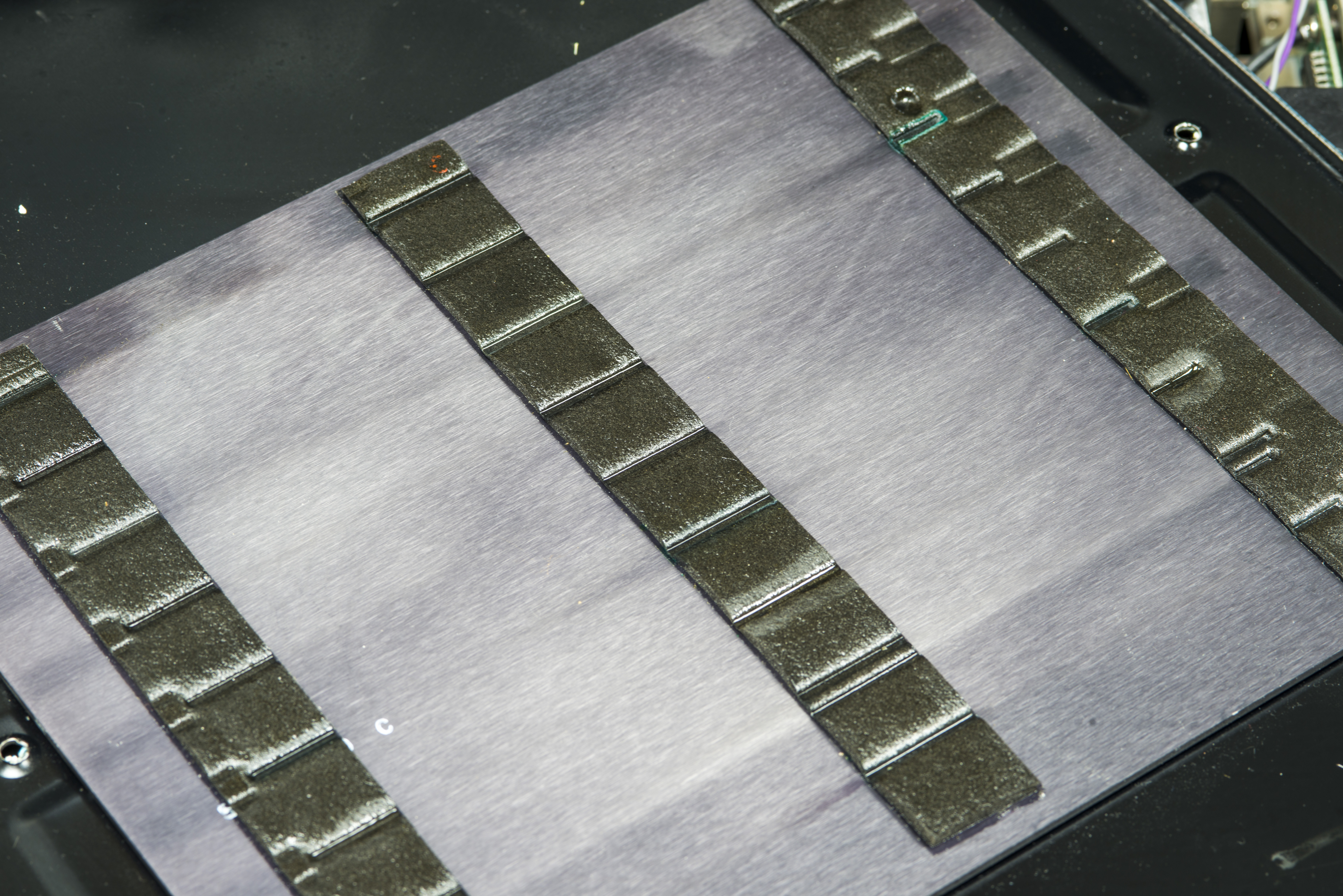
Cover have silicon pads to secure cards when installed.
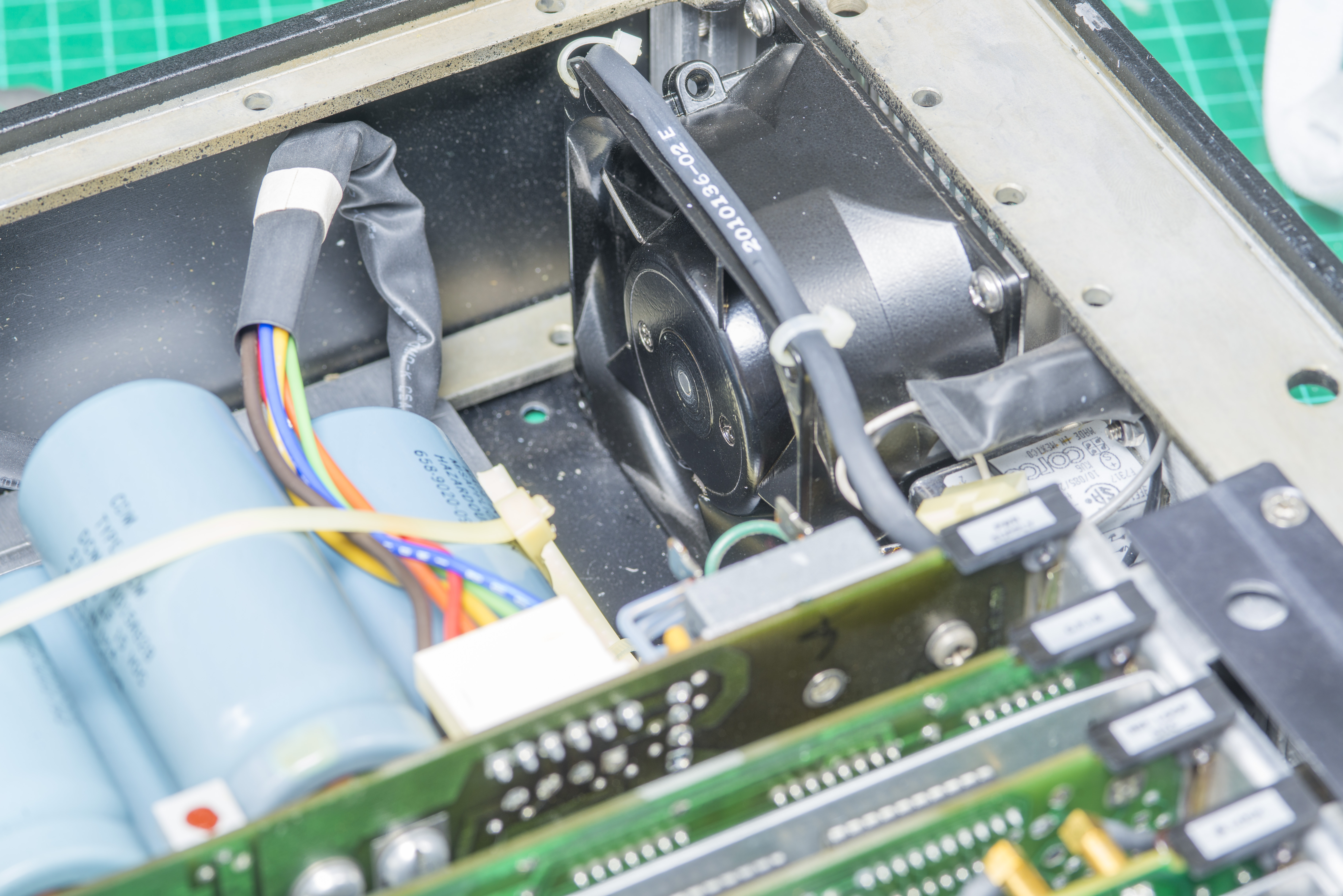
Fan is high quality ebm-papst, and barely audible in operation.
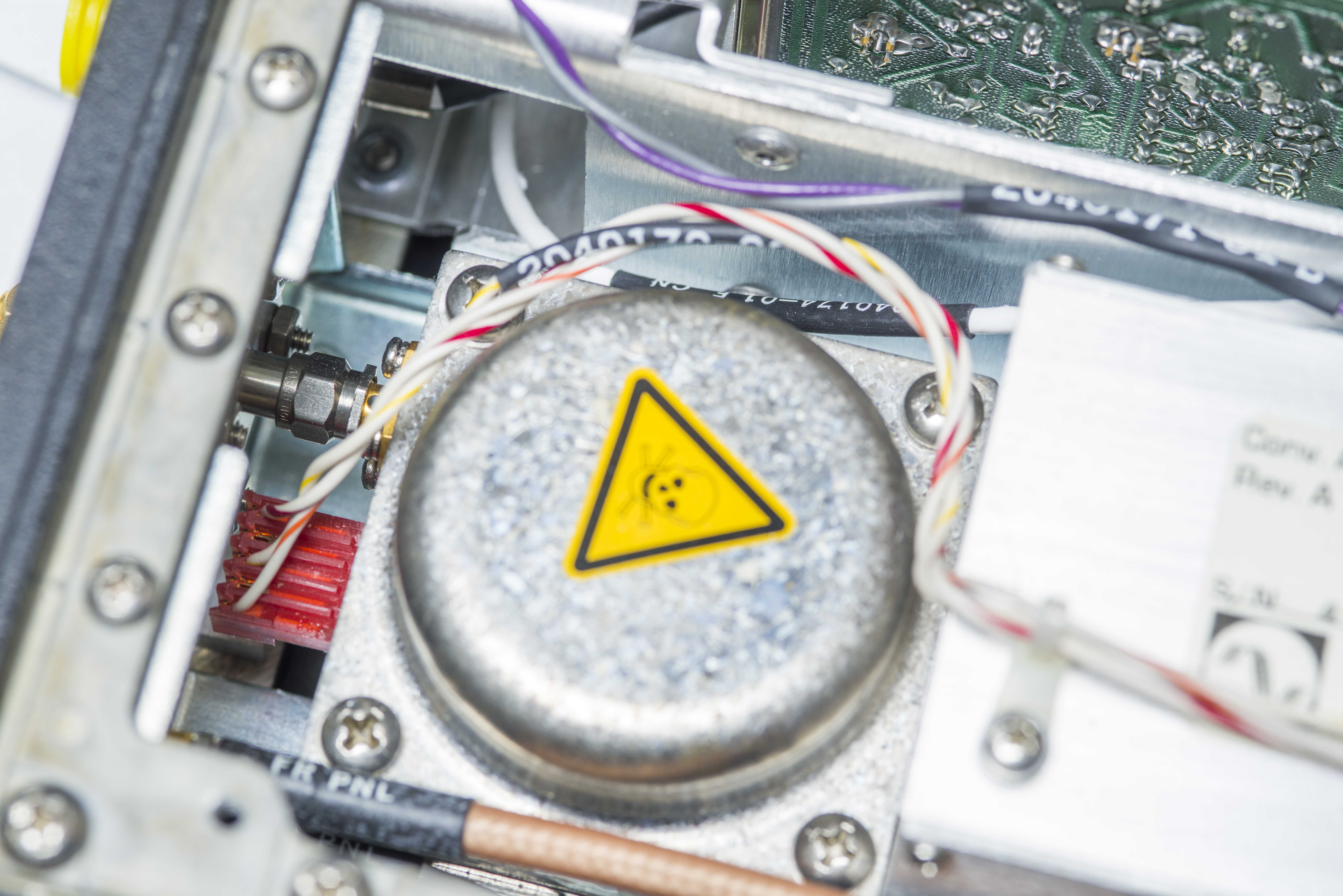
Component assembly with poison warning sign is input YTF filter for Band 3 input.
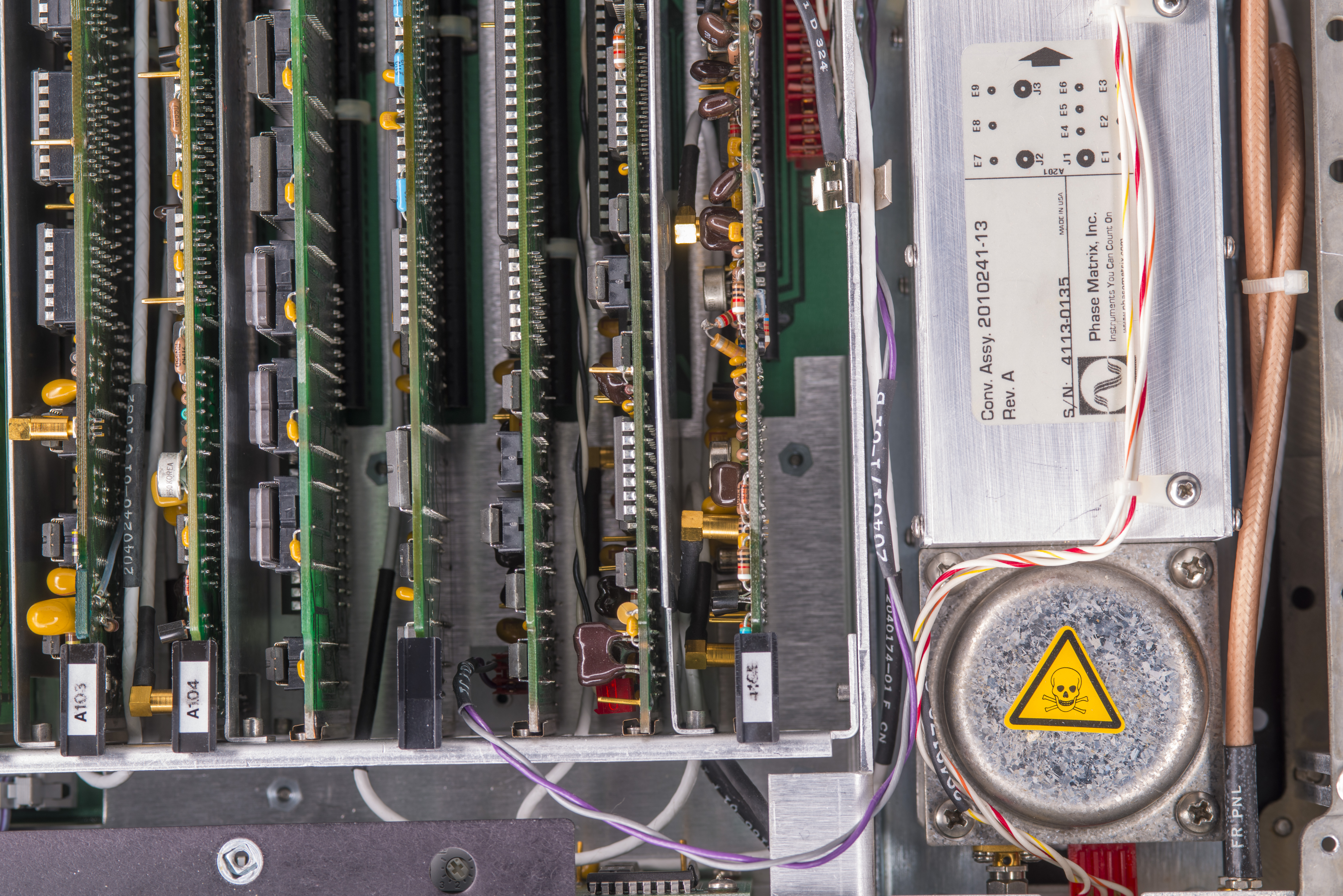
EIP 578B feature a rather unusual for counter component – YIG-based bandpass filter at Band 3 microwave input, which provide additional burnout protection, FM tolerance and frequency selectivity. This filter prevents harmonics and other out-of-band spurious signals from interfering with analysis of the desired signal. It is common component used in high-end spectrum and network analyzers to provide great out of band signal rejection.
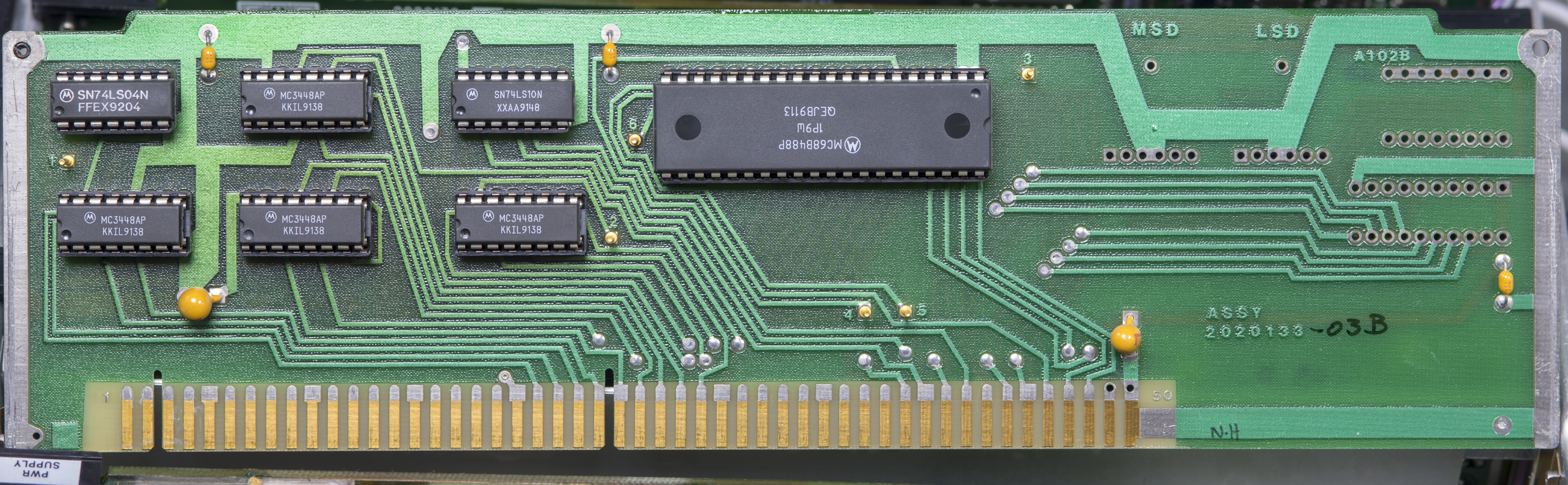
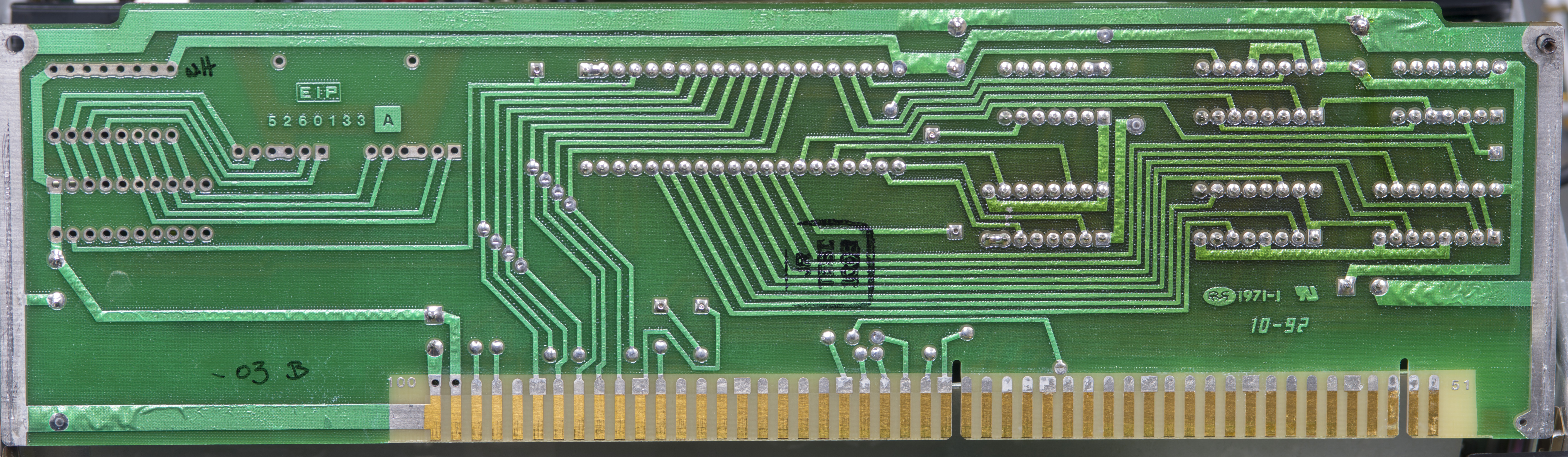
A102 PCB assembly – GPIB interface card
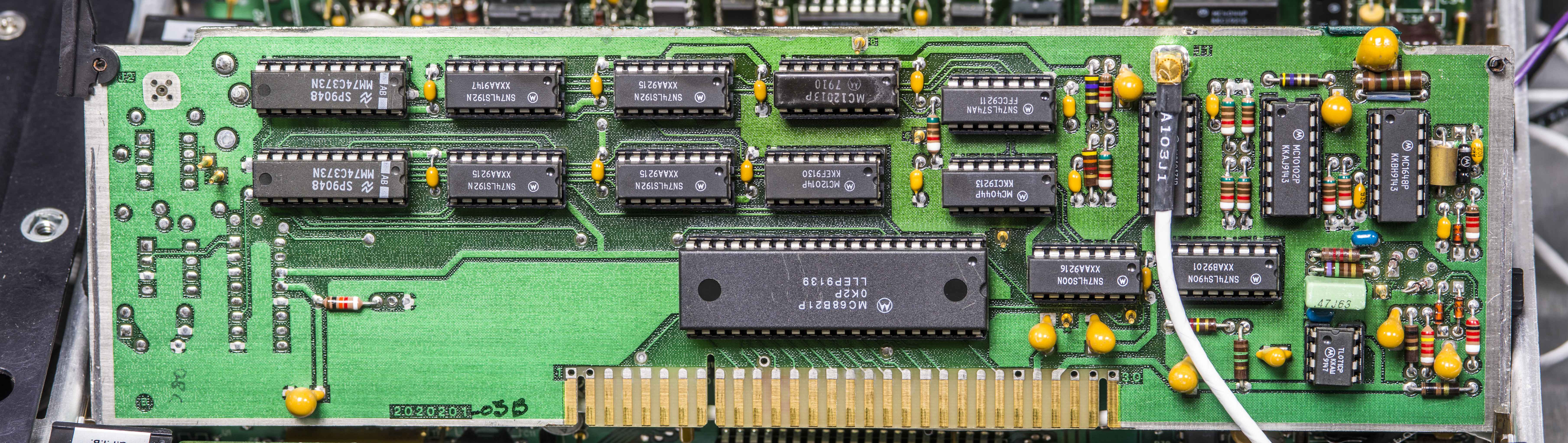
A103 PCB assembly – Reference DAC loop card
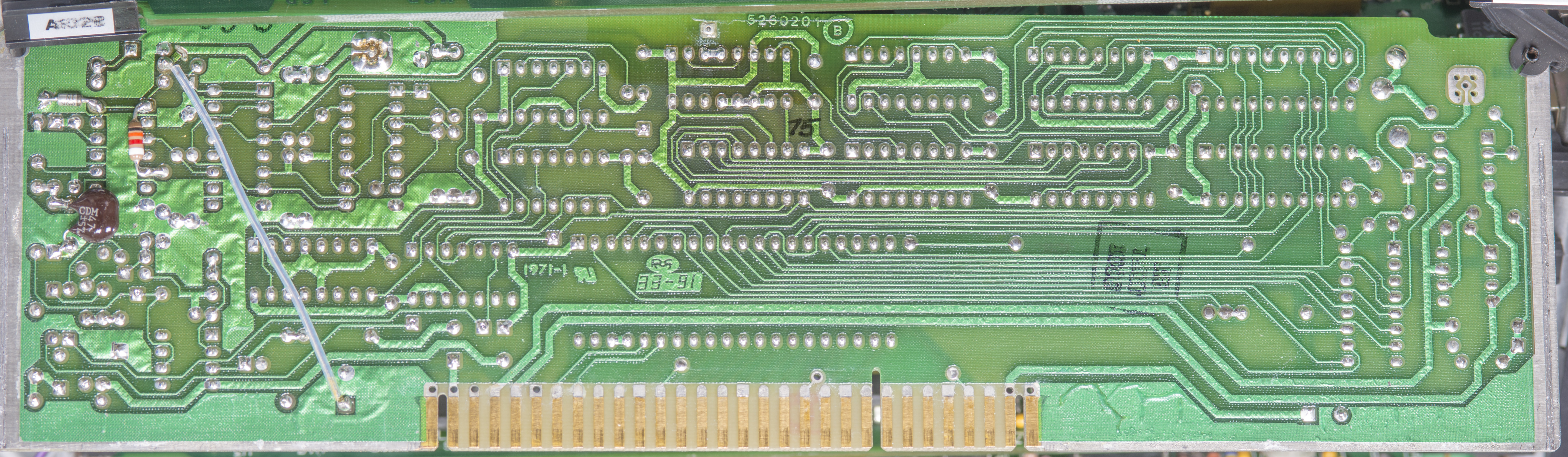
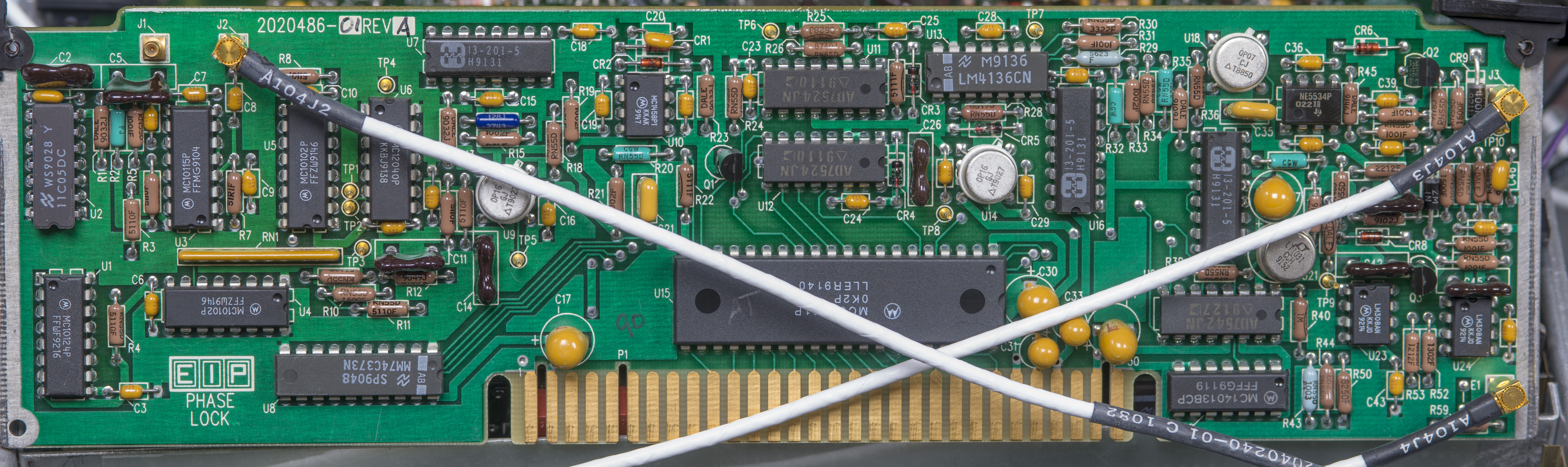
A104 PCB assembly – Phase lock card
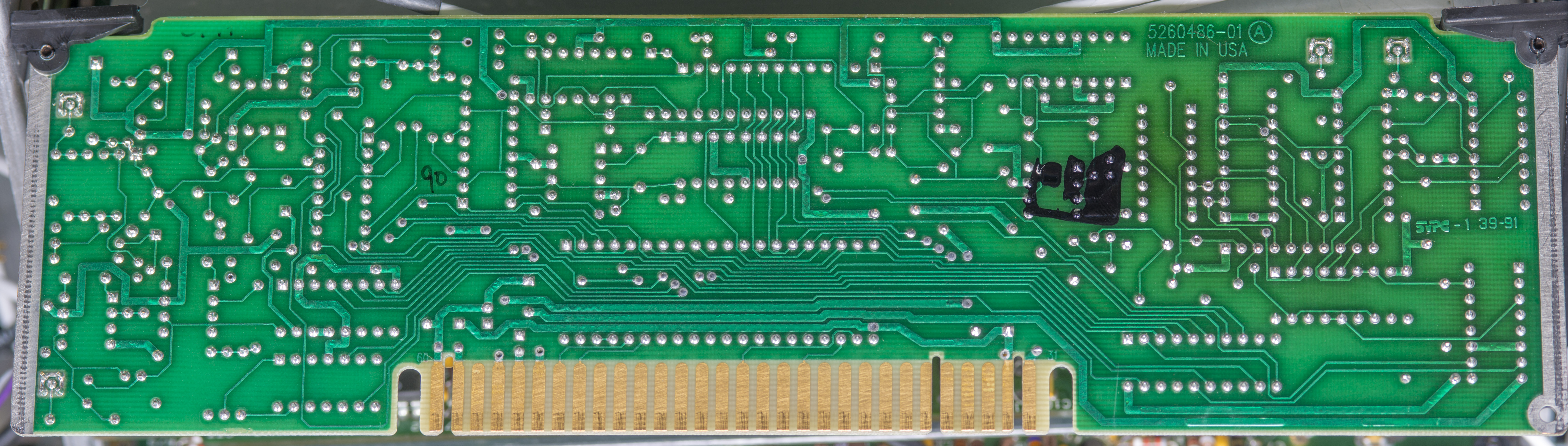
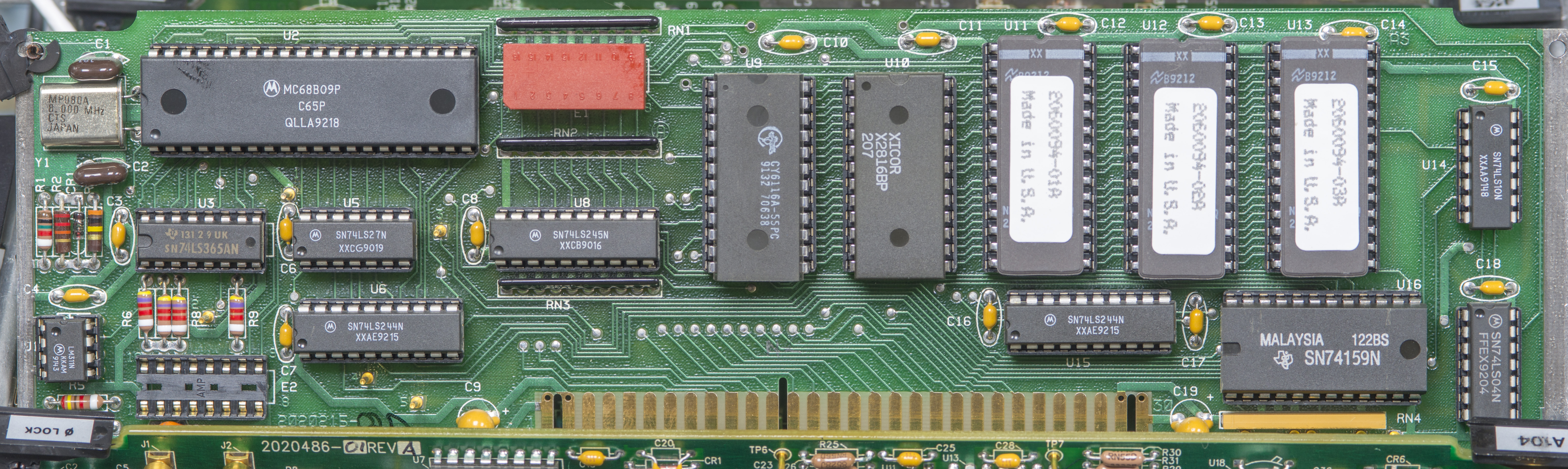
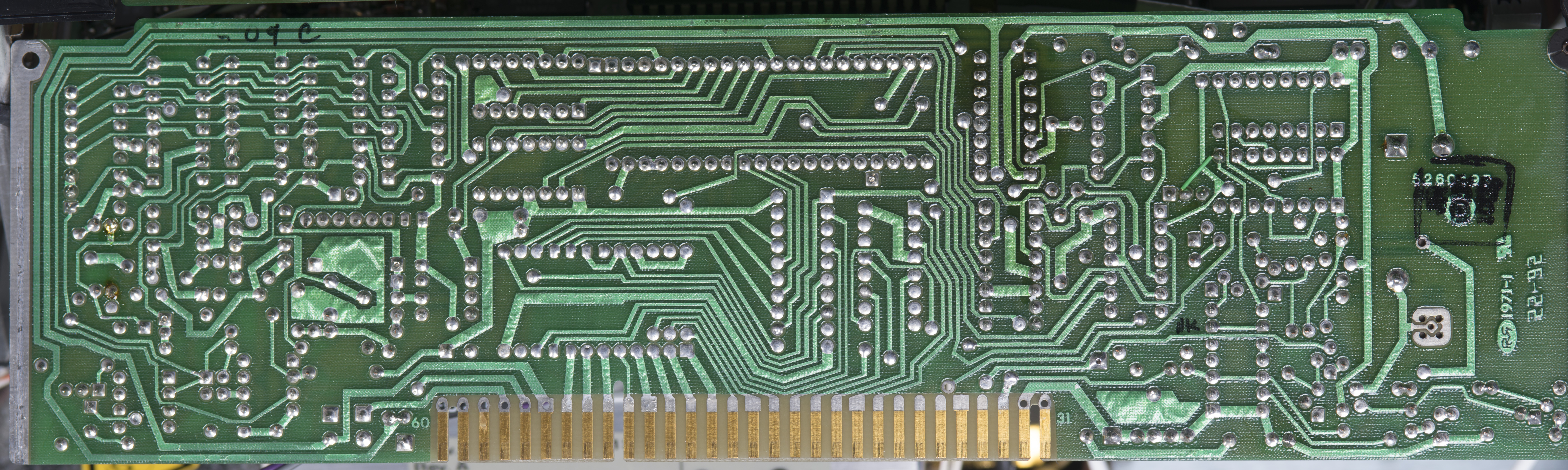
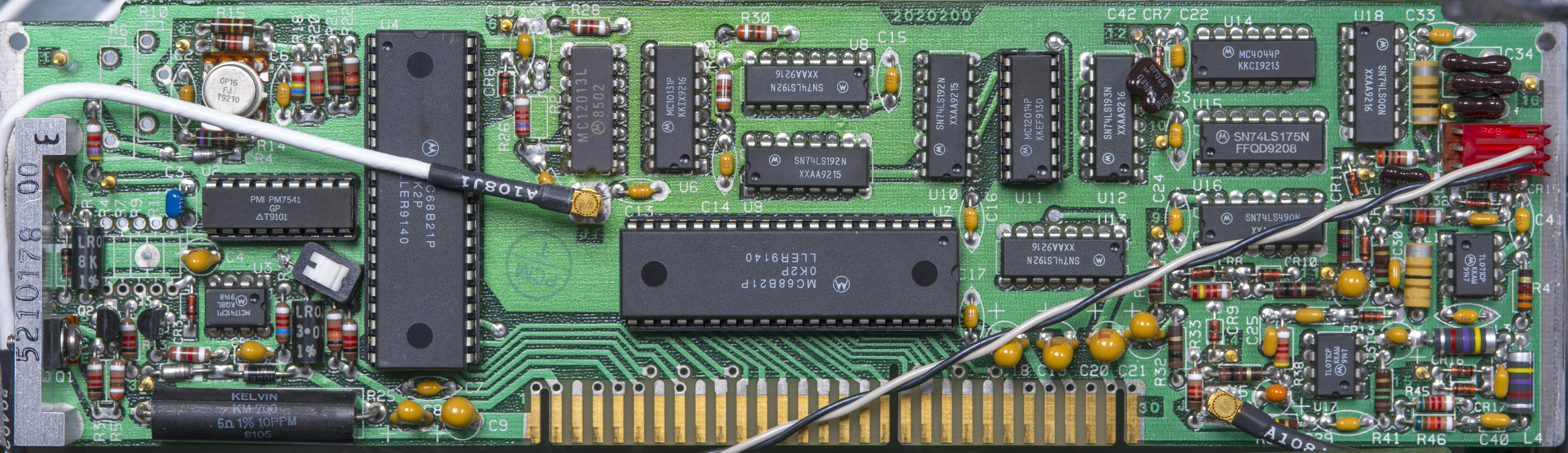
A105 PCB assembly – Processor card
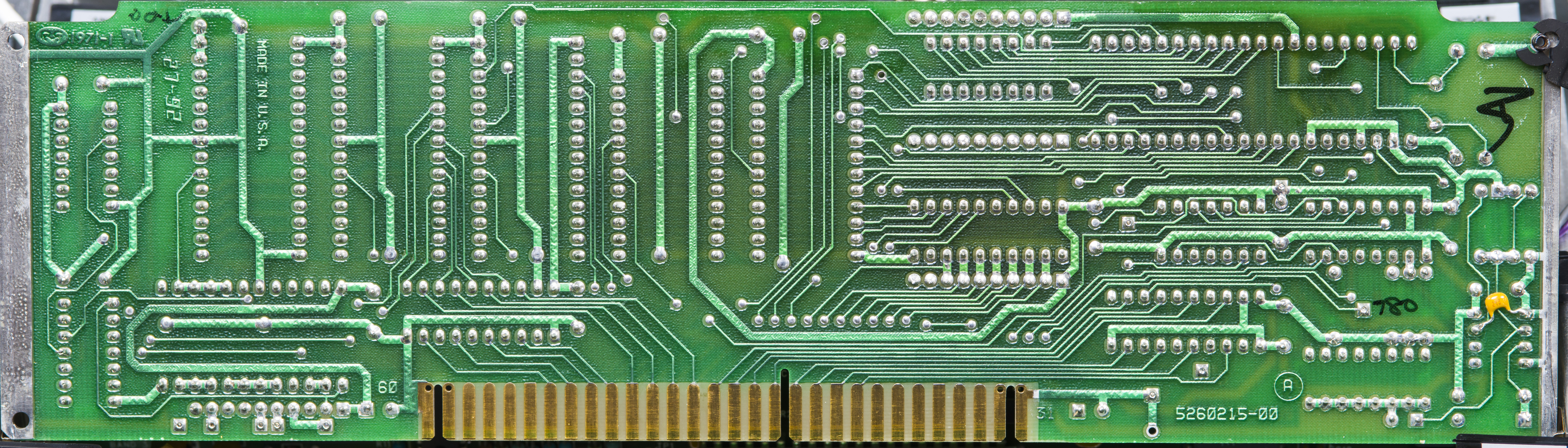
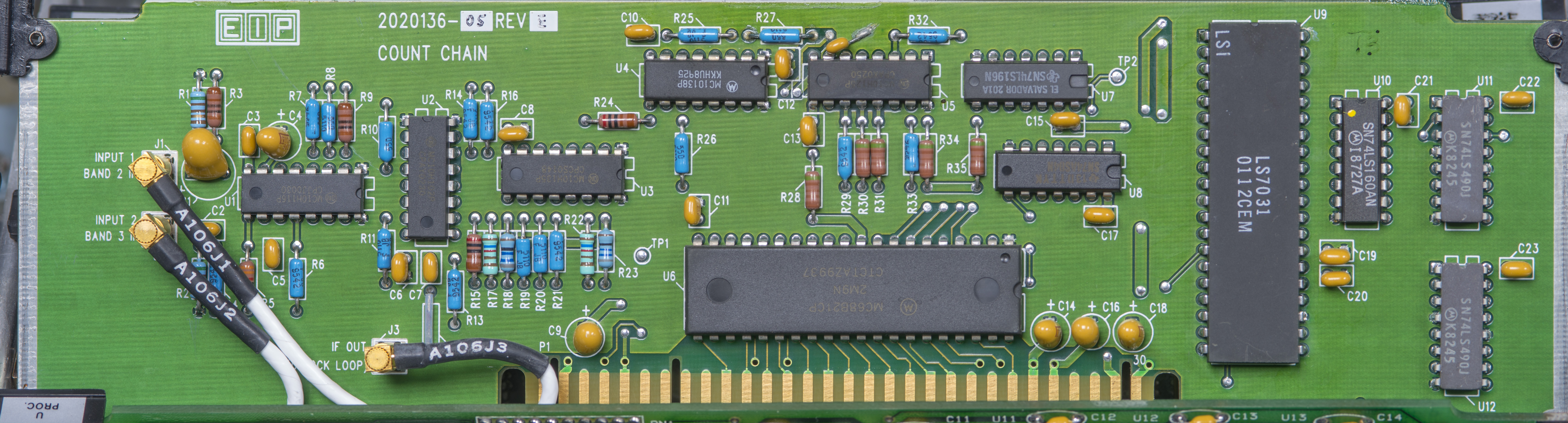
A106 PCB assembly – Counter card
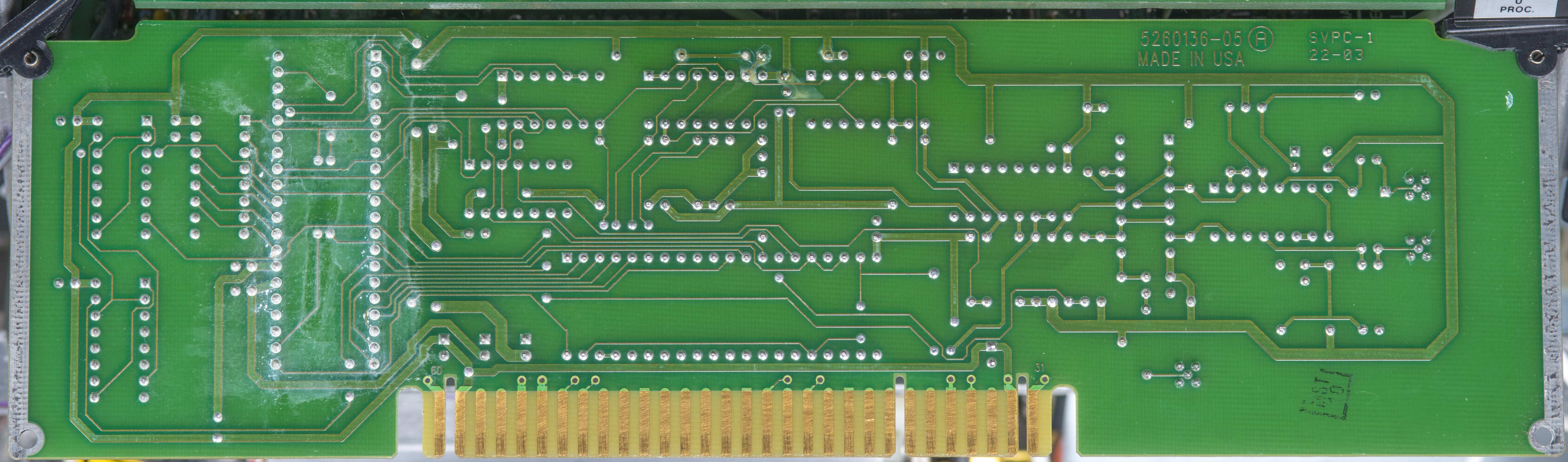
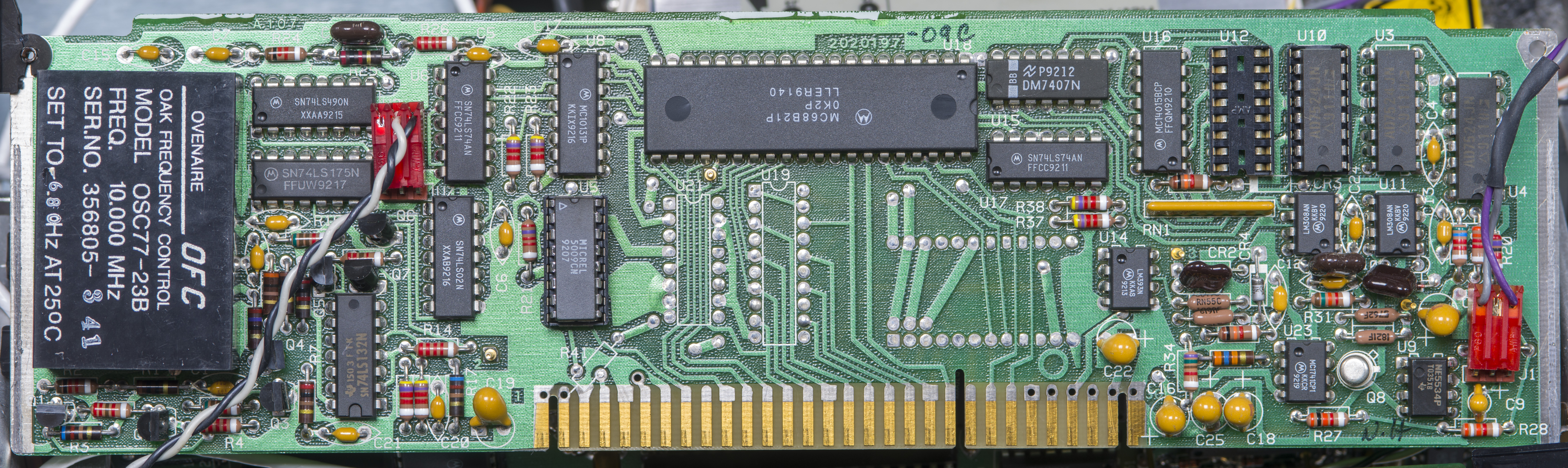
A107 PCB assembly – Gate generator card with reference 10 MHz oscillator
A108 PCB assembly – Band 3 converter

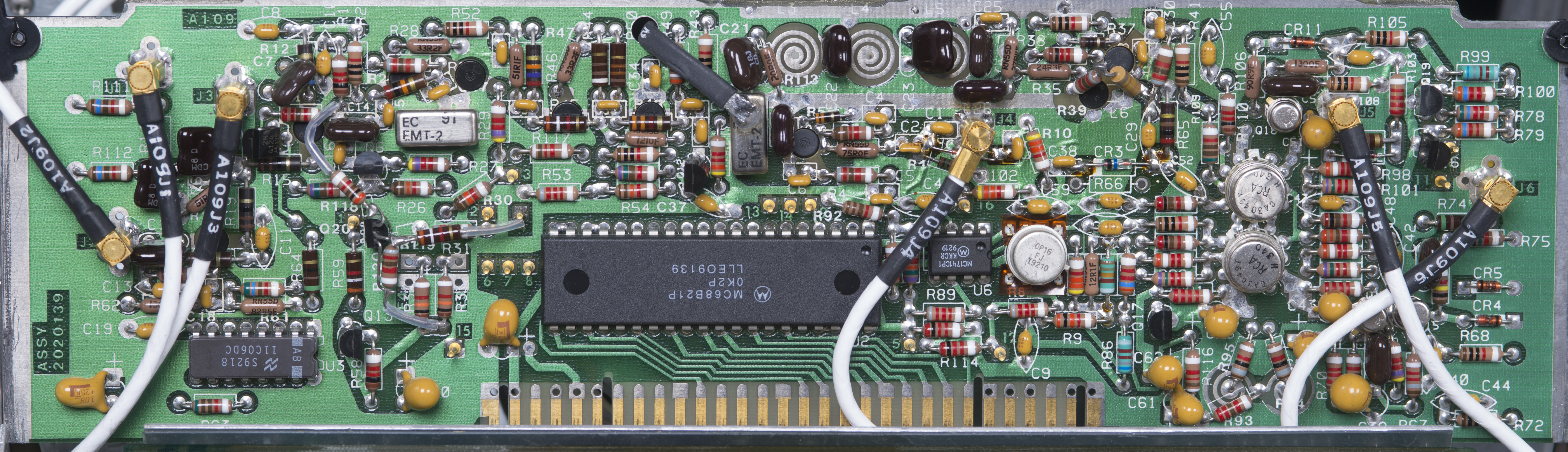
A109 PCB assembly – Band 2 converter

Firmware
Firmware chips were read back by TL866CS programmer
EIP 578B Rev.A 03/30/1992 firmware, U11, NM27CP128Q IC
EIP 578B Rev.A 03/30/1992 firmware, U12, NM27CP128Q IC
EIP 578B Rev.A 03/30/1992 firmware, U13, NM27CP128Q IC
EIP 578B Calibration ROM, Xicor X2816B
External mixer option
Band 4 allow connection of external mixers to measure frequencies higher than 26.5 GHz available at Band 3. We will be exploring this functionality for 60 – 90 GHz band E.
| Remote sensor (EIP type) | Band selected | Frequency range | Waveguide size | Power range |
|---|---|---|---|---|
| 91 | 41 | 26.5 – 40 GHz | WR-28 | -25 to +5 dBm |
| 92 | 42 | 40 – 60 GHz | WR-19 | -25 to +5 dBm |
| 93 | 43 | 60 – 90 GHz | WR-12 | -25 to +5 dBm |
| 94 | 44 | 90 – 110 GHz | WR-10 | -25 to +5 dBm |
| 95 | 42 or 43 | 50 – 75 GHz | WR-15 | -25 to +5 dBm |
| 96 | 41 or 42 | 33 – 50 GHz | WR-22 | -25 to +5 dBm |
| 97 | 41 or 42 | 26.5 – 50 GHz | 3.5mm (K) | -25 to +5 dBm |
Band 4 input on the counter using ITT Sealectro connector. Newer EIP/PhaseMatrix 578B’s use SMA instead.
TBD…
Projects like this are born from passion and a desire to share how things work. Education is the foundation of a healthy society - especially important in today's volatile world. xDevs began as a personal project notepad in Kherson, Ukraine back in 2008 and has grown with support of passionate readers just like you. There are no (and never will be) any ads, sponsors or shareholders behind xDevs.com, just a commitment to inspire and help learning. If you are in a position to help others like us, please consider supporting xDevs.com’s home-country Ukraine in its defense of freedom to speak, freedom to live in peace and freedom to choose their way. You can use official site to support Ukraine – United24 or Help99. Every cent counts.
Modified: Feb. 26, 2021, 10:43 p.m.