- Introduction and motivation
- Disclaimer
- Requirements and specifications of the box
- Project build
- Calibration and verification
- Measurements by receiver
- Summary and conclusion
Introduction and motivation
People who are interested in doing hobby metrology and electrical calibration checks on hobby lab equipment often don’t have needs or access to expensive verified calibration equipment. But there is often significant enough interest to do at least some basic verification with what can be acquired cheaply. One could build few boxes with precision decent quality resistors, capacitors, inductors and voltage references and use them to check typical hobby lab equipment. There is no need for fancy ESI SR104 or Fluke 5730A when it’s okay to have 0.05% uncertainty level.
Number of enthusiasts also building and selling simple low cost check devices, such as VREF10-001 r9 from voltagestandard.com and DMMCheck Plus which allow spot tests of resistance, AC and DC voltages and currents and frequency. There is also more versatile and programmable PDVS2 mini 20-bit DC voltage source from Ian Johnston, which xDevs had reviewed before.
But what if somebody wanted to transfer resistance between two different good labs cheaply. Especially this is interesting over long distance internationally. Shipping large and expensive commercial resistance standard is risky and often expensive. Buying some precision fancy resistor like VPG VHP202 or similar is an option but price is high and often lead-time for these spans into many months. We still are in need to connectorize and protect such resistor from environment too. In this article experiment is set to test idea of going very low cost rugged box with whatever can be found cheaply. I needed to ship small Agilent E5810A to friend in Germany and while packing the box I’ve realized opportunity to add some resistance ppms. But I didn’t want to risk anything of high value during international shipping in winter.
End goal is to have box with magical ohms built AND shipped USD 100 total, excluding any labor and calibration costs.
Disclaimer
Redistribution and use of materials in this article or any files referenced in it, in source and binary forms, with or without modification, are permitted provided that the following conditions are met:
- Redistribution of article must retain the above copyright notice, this list of conditions, link to this page (https://xdevs.com/article/lcrbox/) and the following disclaimer.
- Redistribution of files in binary form must reproduce the above copyright notice, this list of conditions, link to this page (https://xdevs.com/article/lcrbox/), and the following disclaimer in the documentation and/or other materials provided with the distribution, for example Readme file.
All information posted here is hosted just for education purposes and provided AS IS. In no event shall the author, this site, or any other party, including Fluke be liable for any special, direct, indirect, or consequential damages or any damages whatsoever resulting from loss of use, data or profits, whether in an action of contract, negligence or other tortuous action, arising out of or in connection with the use or performance of information published here.
Requirements and specifications of the box
Before project can begin it is important to outline what are desired features:
- Total cost under USD 100, including shipping.
- Rugged enclosure to allow shipping around without risking of physical damage.
- Single resistance output, around 10-ish kΩ.
- Target measurement devices are HP/Agilent/Keysight 3458A, Keithley 2002 or Datron 1281 and similar long-scale DMMs.
- Decent temperature stability, ideally under ±3 ppm/°C.
- Humidity immunity for cross-shipping internationally in regular post.
- Universal four-wire interconnect with 5-way posts to support either banana or spade lug cables.
- Project time under 24 hours, including testing time.
Value around 10 kΩ is a sweet-spot for most of long scale precision DMMs and calibrators. It is in middle of generic DMM resistance ranges scale, large enough not to worry about self-heating and thermal EMFs much, but low enough to allow use regular good quality cables without fully guarded or shielded stuff. Also many labs already own 10 kΩ standards so using this value range allows easier comparison and better quality measurements.
Project build
Back in 2021 I’ve bought Fluke 4250A BCD programmable power source. In today’s market with wide availability of integrated DAC products usability of 4250A for intended purpose is somewhat questionable. It is essentially big box with some old circuit boards and sets of famous golden can Fluke hermetic resistors. Resistors are used to determine levels of it’s internal discrete DAC generator output. Now it is time to reuse one of those resistors in this little project. There is also similar Fluke 4270A device as alternative.

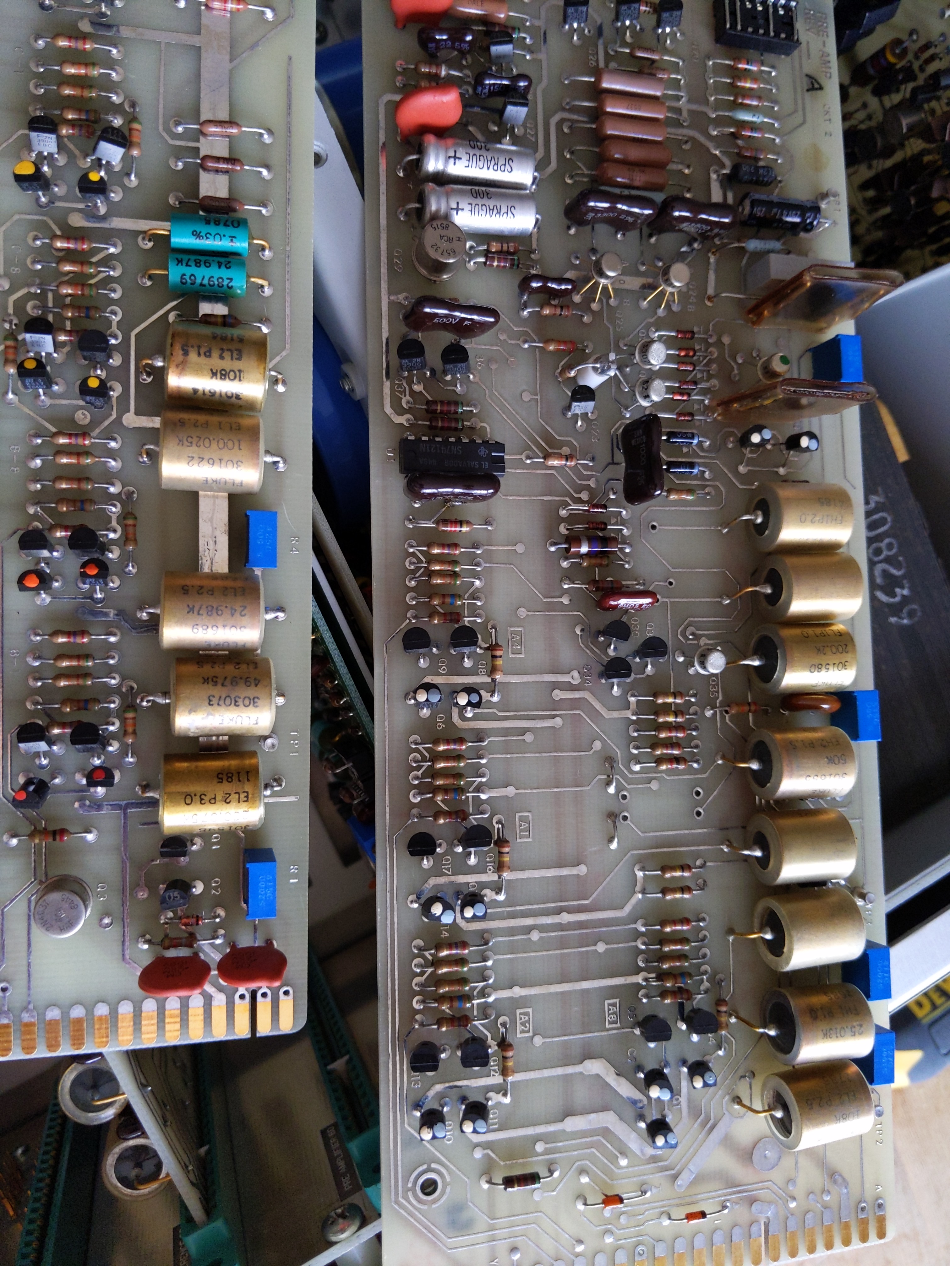
Image 1: Fluke 4250A BCD source
After quick de-soldering job we are greeted with whole array of pretty looking precision wire-wound resistance elements, custom made by Fluke.
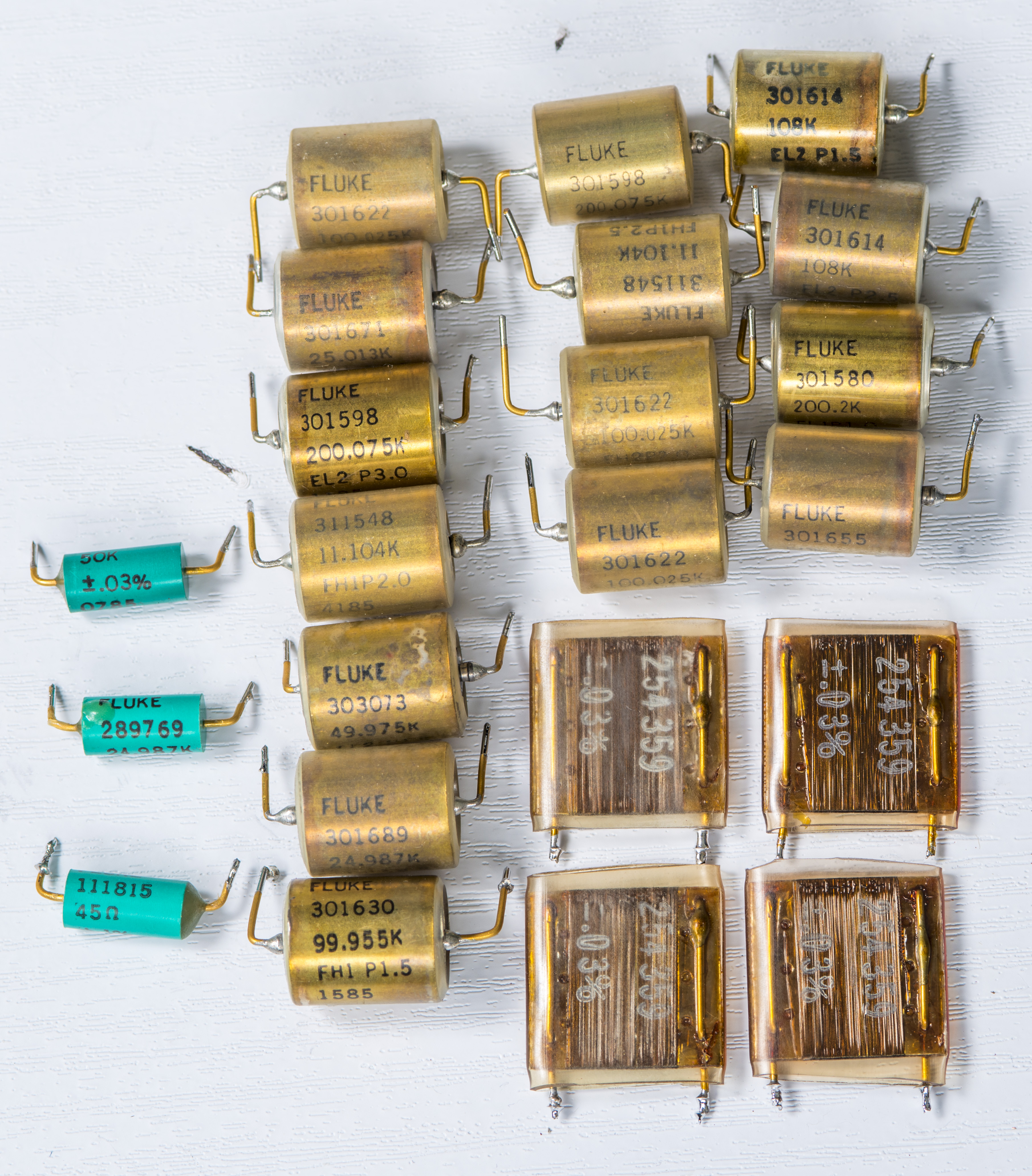
Image 2: Salvaged precision resistors
Teal epoxy or mica card resistors would not satisfy our requirement to be rugged and immune to humidity due to exposure of wire to outer world. Out of sealed can-type resistors most are pretty high in resistance values, but two elements that are great candidates, Fluke P/N 311548.
These two resistors have printed resistance 11104 Ω which is well inside the base resistance range of the HP 3458A DMM. They both manufactured on 41st week 1985 and marked with positive temperature coefficient at few ppm/°C.
Now let’s pick some connectors, enclosure and use these parts to build a box over a weekend using few hours in lab.
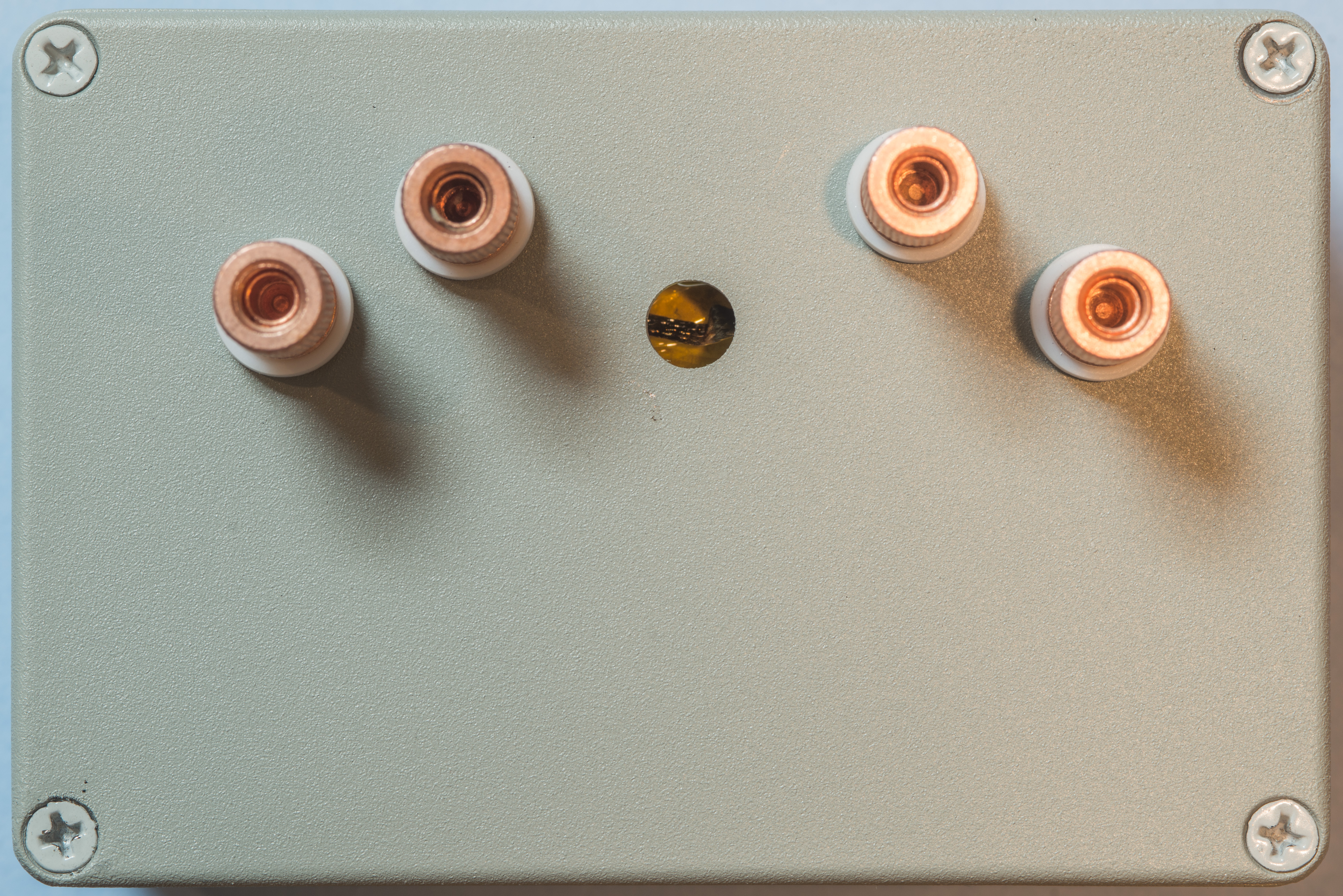
Image 3: Low-cost transfer resistance box, top side
I’ve drilled five 8.5mm holes and installed copper 5-way binding posts from previous group order. Each post supports both banana and spade lug type measurement cables. Force and sense terminals on each side have spacing to allow use with dual banana adapter if such need arise.
Spacing out connector horizontally allows more room for easier cable connection convenience. Each copper post is mounted with PTFE ring insulators to fully isolate terminals from metal enclosure body.

Image 4: Internal construction and interconnect
Sense terminals are shielded with guard potential, connected to cheap brass post in center between standard output binding posts. Current terminals are edge ones and connected to short wire at the resistor element itself. Fluke resistor brass body also connected to guard shield by soldering at the corners.
Thermally insulated padding is placed around to fill up inner volume and prevent most of the resistor movement inside the enclosure during normal use or shipping. All connections to resistor and posts was done with regular 6040 solder.
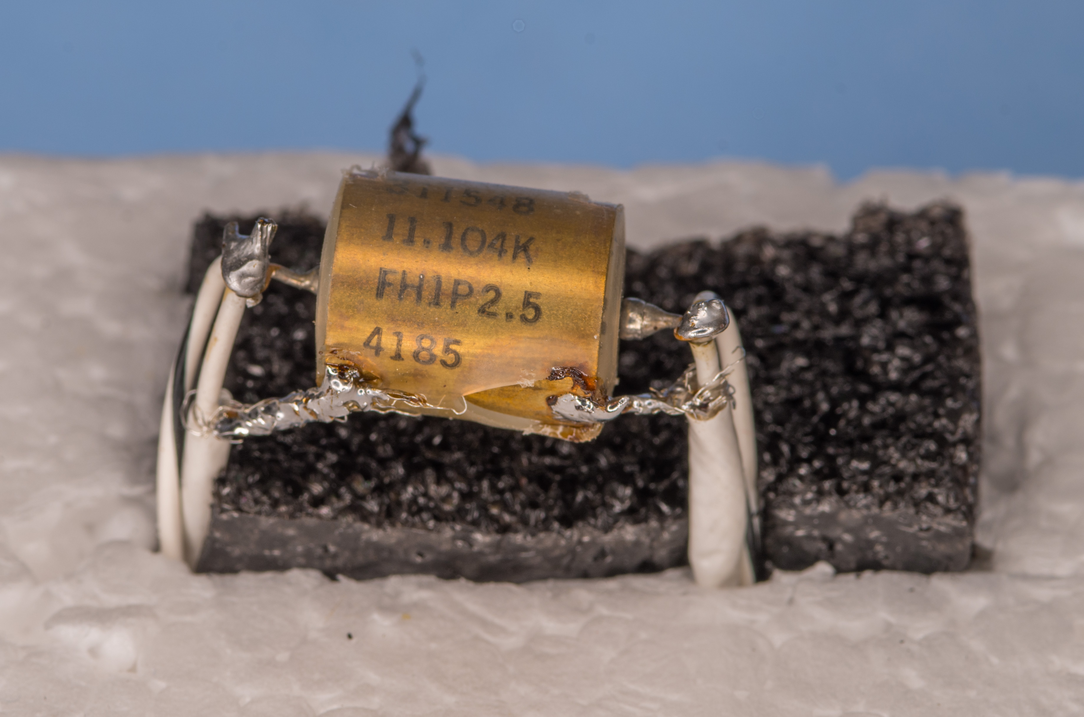
Image 5: Hermetic resistor, P2.5 marking means +2.5 ppm/°C specification
Resistor was not tested or selected in any way previously. High-ish 11.104 kΩ value could be handy to enable possible output trim close to desired cardinal 10 kΩ by using external trim resistor in parallel. Such trim resistor would need to have value around 100.58 kΩ to obtain value within few ppm from 10 kΩ nominal.
But trimming resistance would increase cost, add need for additional time for tests and likely cause multiple iterations, increasing risk of failing the target goals of under 24 hour project time and USD 100 shipped cost. And all that effort would be not very useful, since only stability is important in successful resistance transfer. HP3458A doesn’t care if reference value is 9926 Ω or 12345 Ω, as far as it fits under maximum range limit which is 11999.990 Ω. Reliability and often better performance is another possible benefit of having no trim elements in circuit. Extra components and joints often result in more points of failure, drift and instabilities.
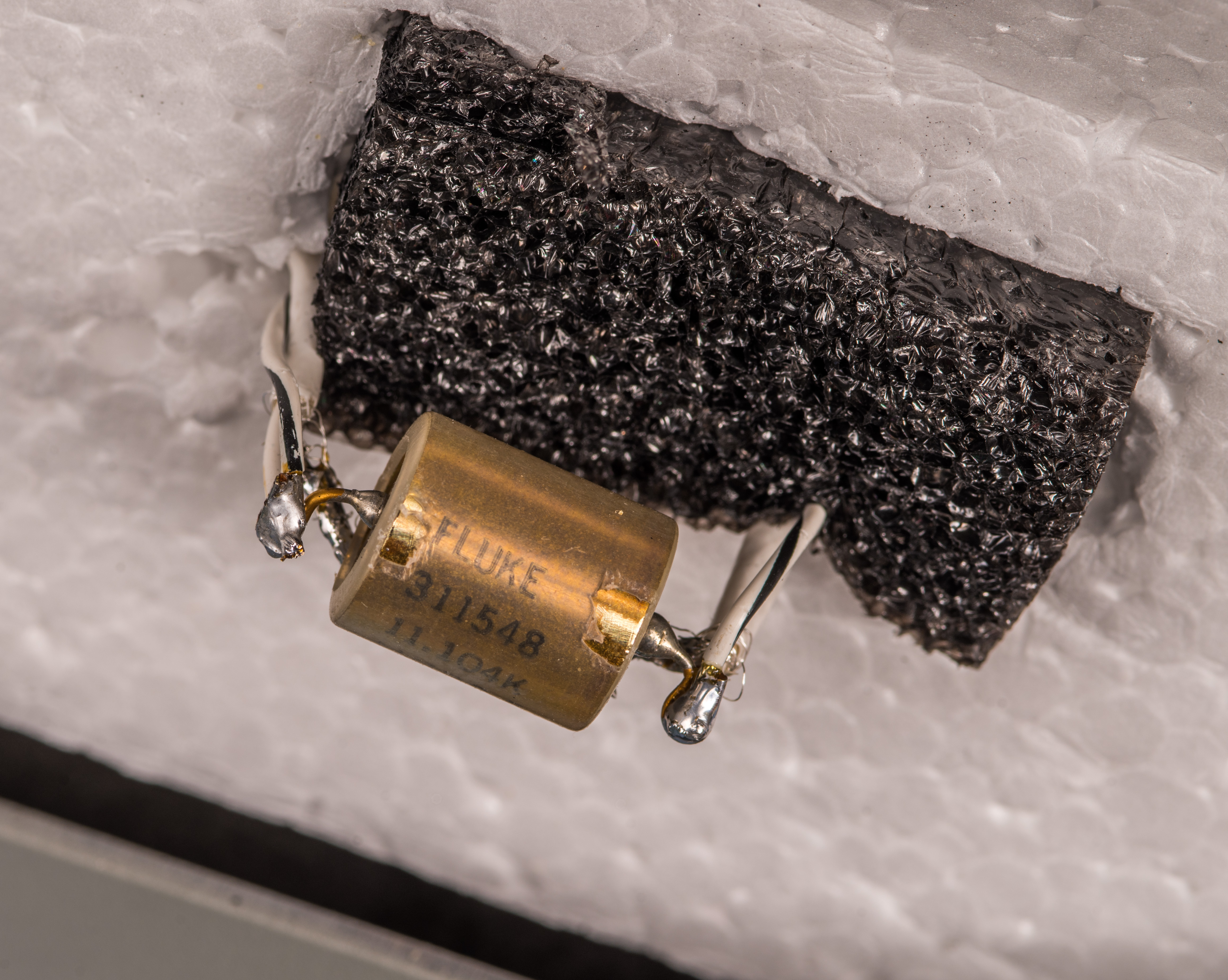
Image 6: Oil-filled precision wire-wound hermetic resistor
I quite like these low-cost copper posts. They allow full removal of mounting nut and provide easy access to cleaning. Cleaning is important since these copper posts are not plated and will oxidize over time due to exposure to elements.
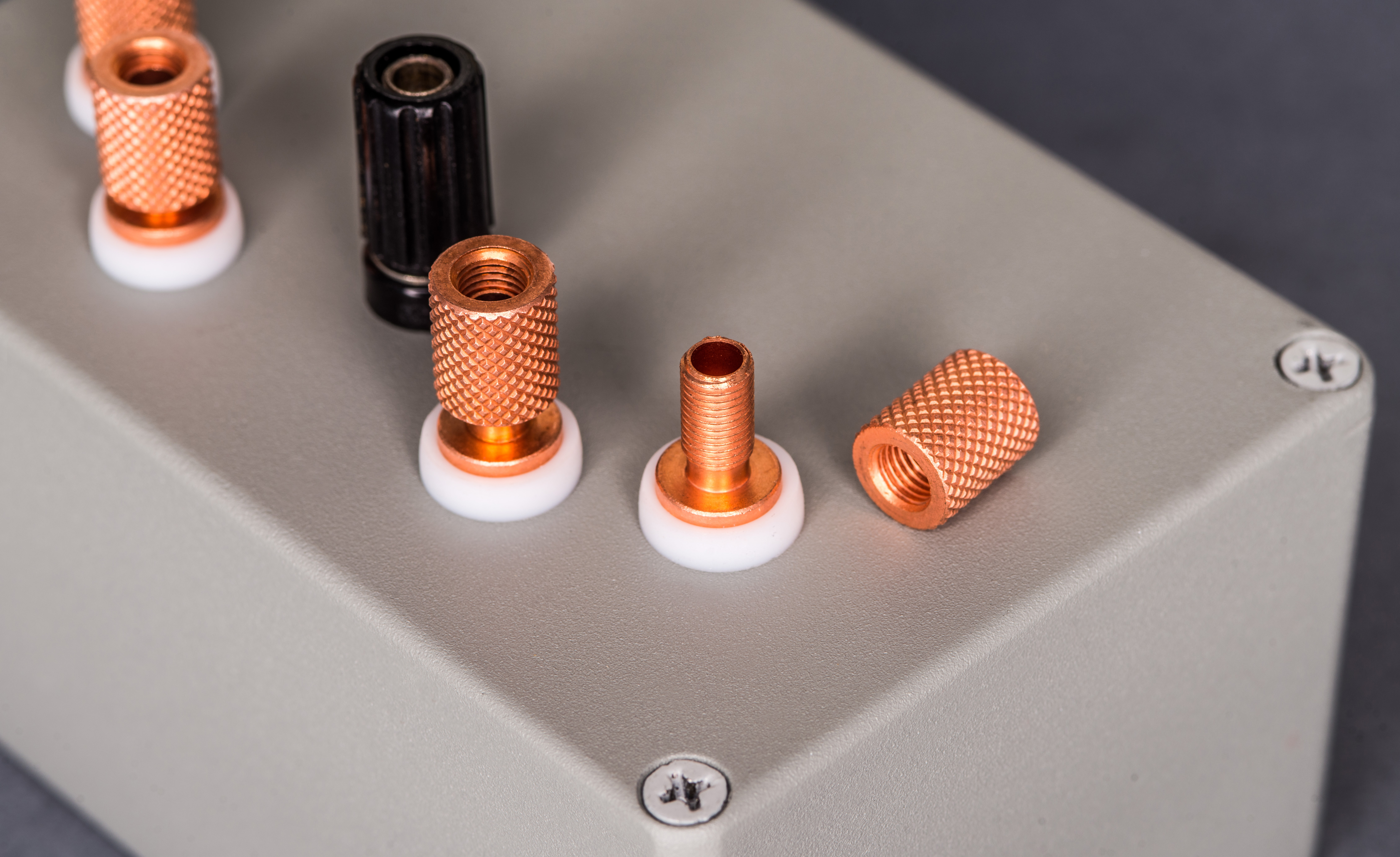
Image 7: Copper 5-way binding terminal
Box is reassembled and sealed with four screws bundled with Hammond 1590TGY enclosure. There is no separate post for chassis, but grounding wire can be connected to one of the corner screws, if desired.
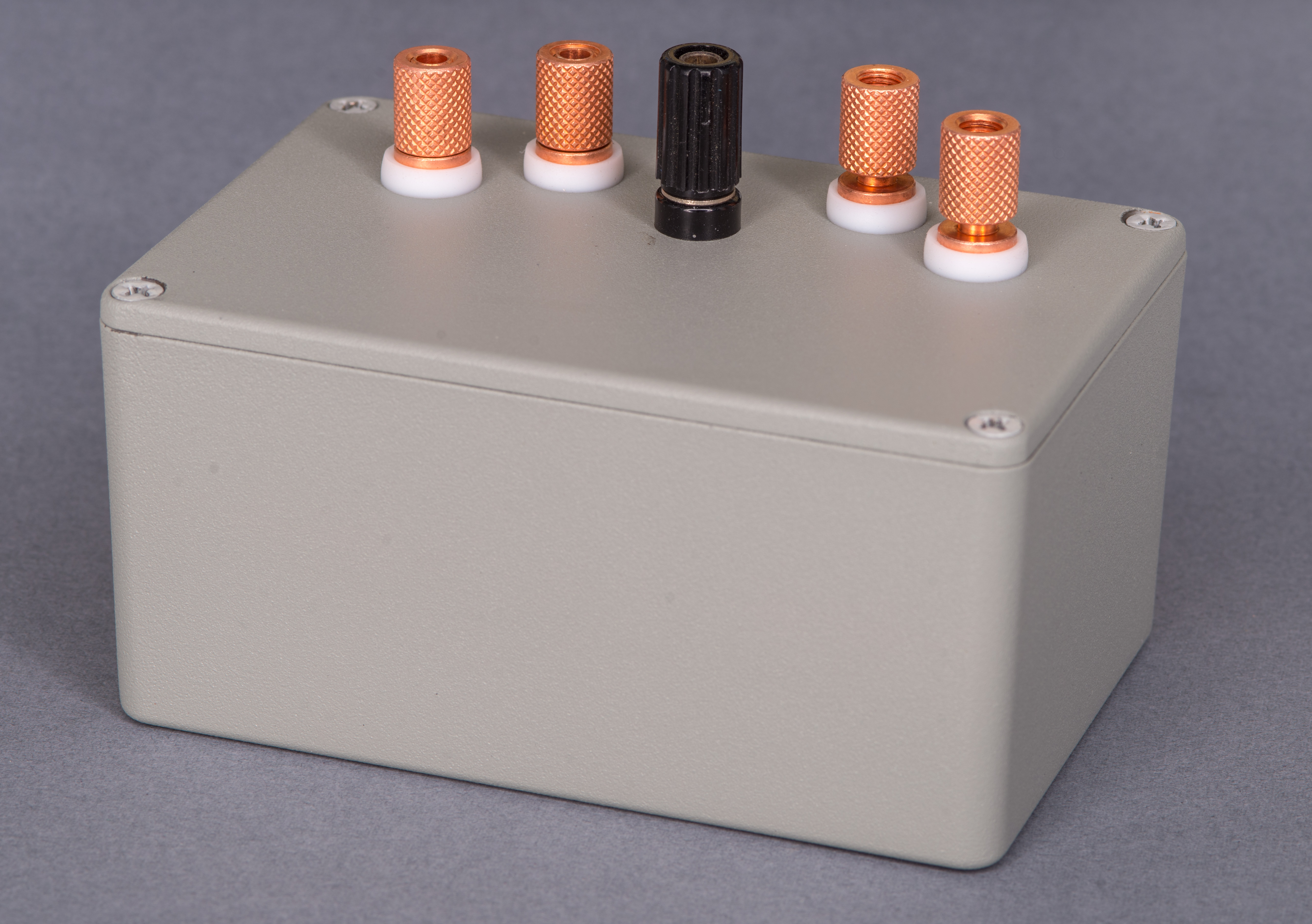
Image 8: Assembled box before measurements
Box is painted in gray color by manufacturer.
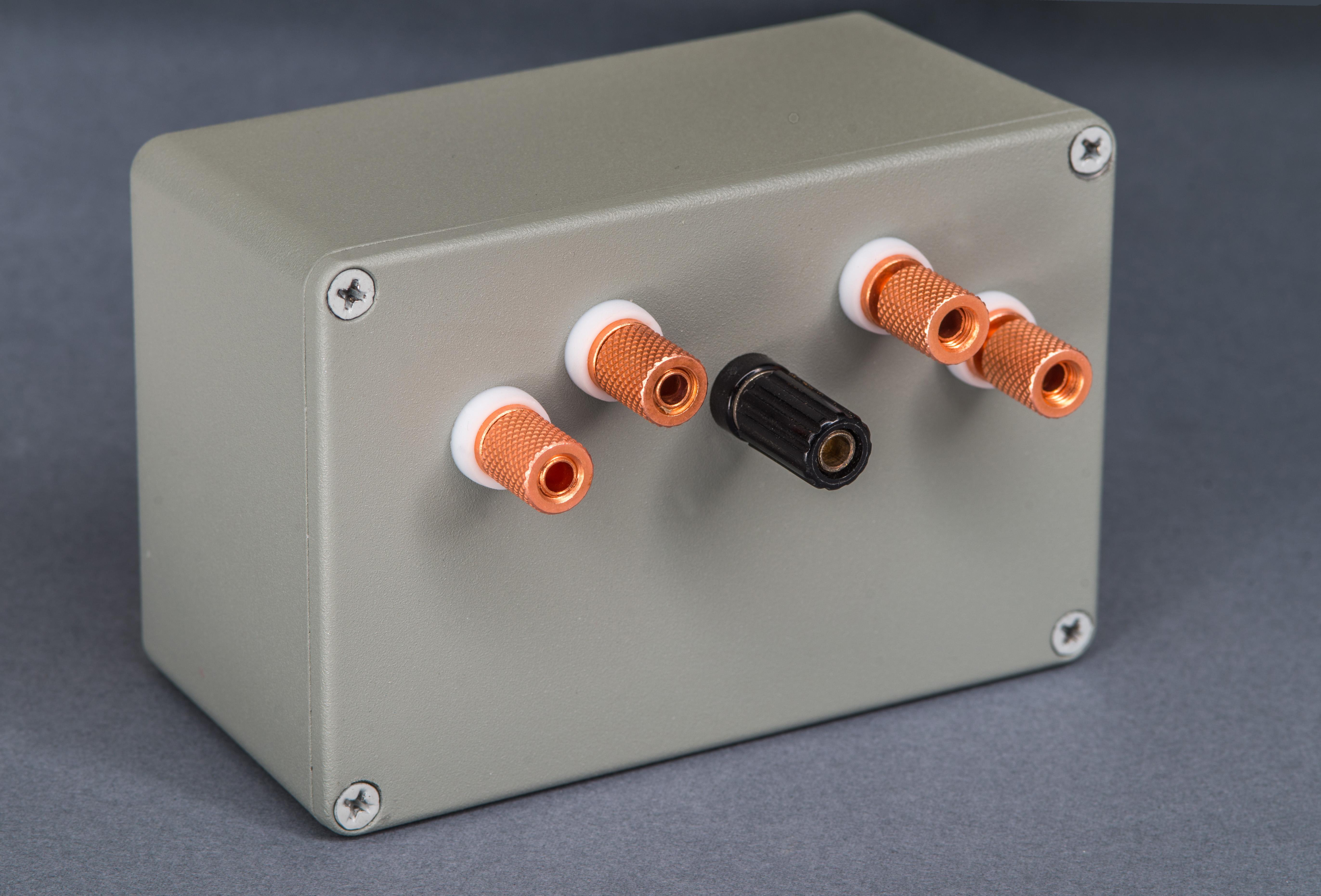
Image 9: Assembled box before measurements
Perhaps added temperature sensor would be beneficial for such resistance transfer box, but given it’s small size and limited budget it was determined to opt out of dedicated temperature sensor in box.
Calibration and verification before shipment
Calibration system was equipped with 9½-digit resistance bridge from Measurements International, Model 6010. Characterized 1 kΩ transfer resistance standard xDevs.com RWS103, freshly calibrated from ESI SR104 10000 Ω standard was used as reference.
Control platinum resistance thermometer was placed into guard post, making mechanical contact for reliable thermal transfer during temperature sweep measurement. Thermometer was readout by Fluke 1529 Chub-E4.
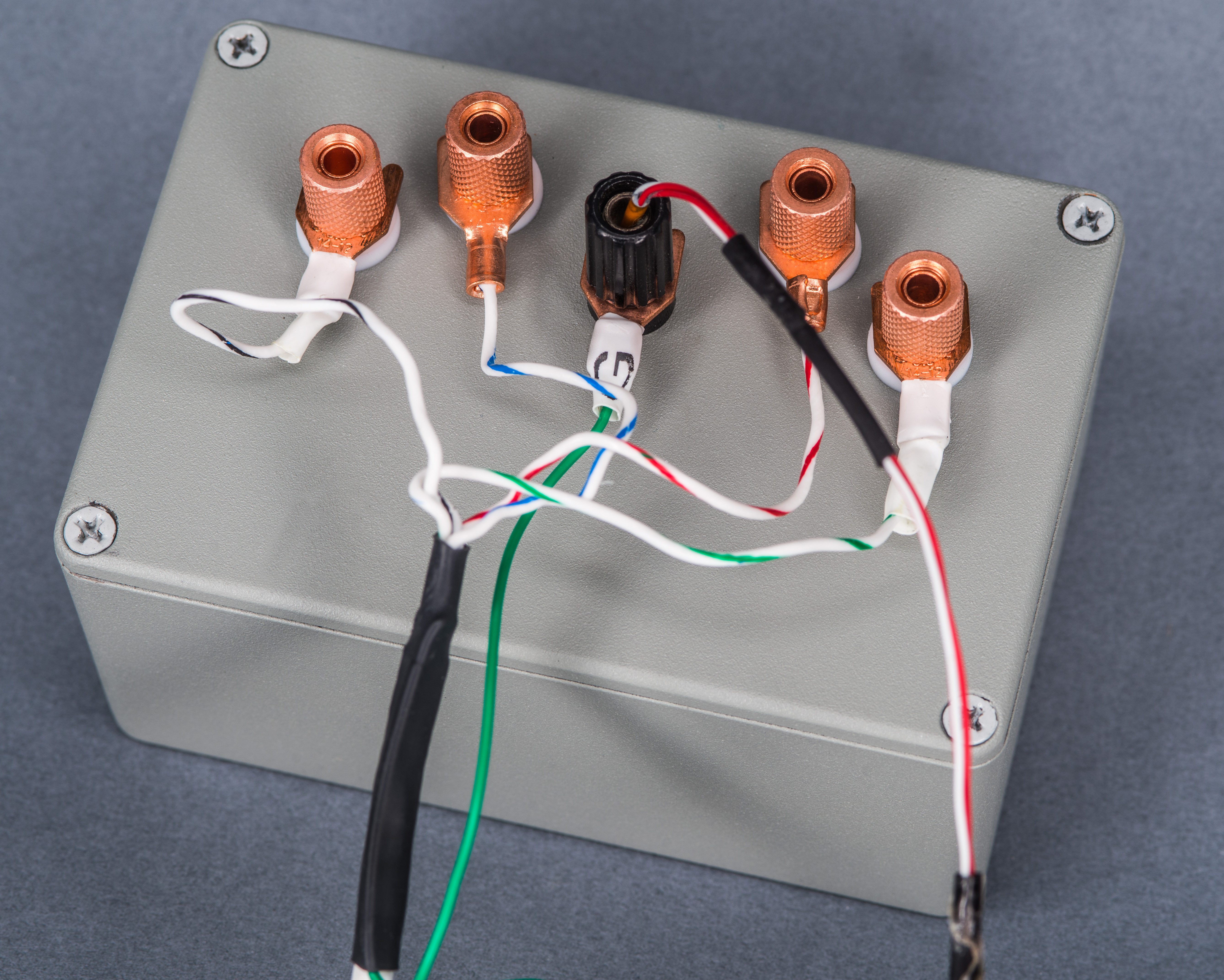
Image 10: Four-wire connections to resistance transfer unit with RTDCAP Pt1000 element location
Measurements International 6010B direct current comparator was configured with test current 200 µA and both the RWS103 and DUT 11.1 kΩ were placed in own air baths.

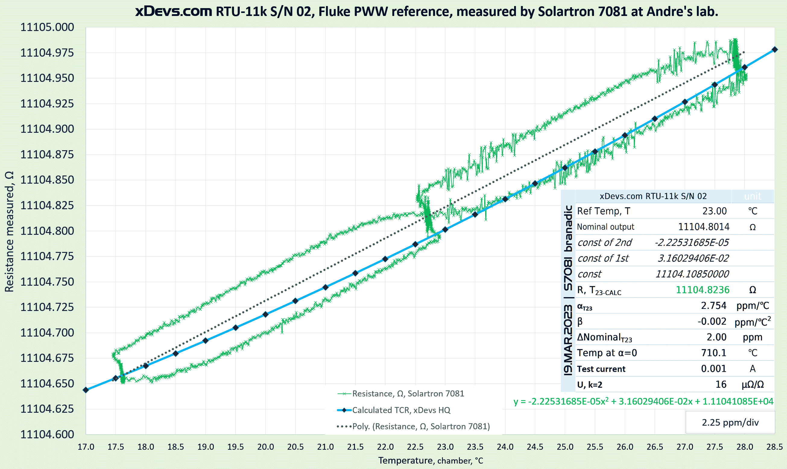
Image 11: Measured sweep with temperature data. Click on image for Excel-datafile with RAW values
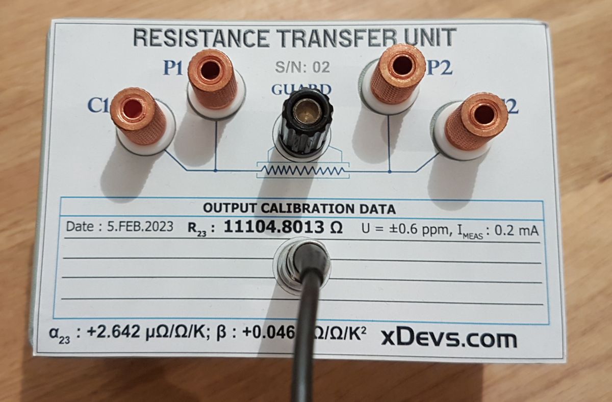
With data from this calibration we can calculate resistance at reference temperature +23.0 °C, which is 11104.8013 Ω. Actual measured temperature coefficient α = +2.642 ppm/°C and β = +0.046 ppm/°C2. These results are consistent with Fluke marking +2.5 ppm/°C. Reversal of TCR curve calculated to be at -5.92 °C.
Retrace hysteresis due to temperature change is quite good for this standard, around 1 ppm from +5 °C excursion. TCR measurement test sweep took 22 hours, with points key levels at +23.2 °C, +28.9 °C, +20.2 °C and final return to +23.2 °C. Final ratio deviation after this was under 1 ppm from original value at the beginning of the test.
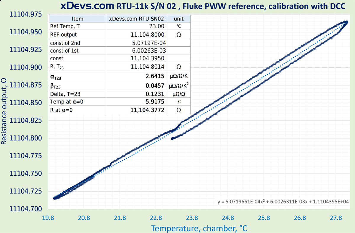
Image 12: Calculated temperature coefficients and calibration values
Using determined α +2.642 ppm/°C and β = +0.046 ppm/°C2 output resistance can be accurately calculated at any desired temperature.
| Temperature RTU-11k S/N 02 | Resistance output, Ω | Deviation vs TCAL23, µΩ/Ω |
|---|---|---|
| 16.0 °C | 11104.6210 Ω | -16.240 µΩ/Ω |
| 16.5 °C | 11104.6322 Ω | -15.229 µΩ/Ω |
| 17.0 °C | 11104.6437 Ω | -14.196 µΩ/Ω |
| 17.5 °C | 11104.6554 Ω | -13.139 µΩ/Ω |
| 18.0 °C | 11104.6674 Ω | -12.060 µΩ/Ω |
| 18.5 °C | 11104.6796 Ω | -10.957 µΩ/Ω |
| 19.0 °C | 11104.6921 Ω | -9.832 µΩ/Ω |
| 19.5 °C | 11104.7049 Ω | -8.684 µΩ/Ω |
| 20.0 °C | 11104.7179 Ω | -7.512 µΩ/Ω |
| 20.5 °C | 11104.7312 Ω | -6.317 µΩ/Ω |
| 21.0 °C | 11104.7447 Ω | -5.100 µΩ/Ω |
| 21.5 °C | 11104.7585 Ω | -3.859 µΩ/Ω |
| 22.0 °C | 11104.7725 Ω | -2.596 µΩ/Ω |
| 22.5 °C | 11104.7868 Ω | -1.309 µΩ/Ω |
| 23.0 °C | 11104.8013 Ω | +0.000 µΩ/Ω |
| 23.5 °C | 11104.8161 Ω | +1.332 µΩ/Ω |
| 24.0 °C | 11104.8312 Ω | +2.688 µΩ/Ω |
| 24.5 °C | 11104.8465 Ω | +4.066 µΩ/Ω |
| 25.0 °C | 11104.8620 Ω | +5.468 µΩ/Ω |
| 25.5 °C | 11104.8779 Ω | +6.893 µΩ/Ω |
| 26.0 °C | 11104.8939 Ω | +8.340 µΩ/Ω |
| 26.5 °C | 11104.9103 Ω | +9.810 µΩ/Ω |
| 27.0 °C | 11104.9268 Ω | +11.304 µΩ/Ω |
| 27.5 °C | 11104.9437 Ω | +12.821 µΩ/Ω |
| 28.0 °C | 11104.9608 Ω | +14.360 µΩ/Ω |
| 28.5 °C | 11104.9781 Ω | +15.923 µΩ/Ω |
| 29.0 °C | 11104.9957 Ω | +17.508 µΩ/Ω |
| 29.5 °C | 11105.0136 Ω | +19.116 µΩ/Ω |
| 30.0 °C | 11105.0317 Ω | +20.748 µΩ/Ω |
| 30.5 °C | 11105.0501 Ω | +22.402 µΩ/Ω |
| 31.0 °C | 11105.0687 Ω | +24.080 µΩ/Ω |
| 31.5 °C | 11105.0876 Ω | +25.780 µΩ/Ω |
| 32.0 °C | 11105.1067 Ω | +27.504 µΩ/Ω |
Measurements by receiver
This project would be pointless without actual international shipping. This box was shipped by regular postal carrier on February 6, 2023 to Germany and delivered March 2, 2023. Destination lab for this unit belongs to xDevs.com’s contributor and good friend, Dipl.-Ing. André Bülau also known as branadic in xDevs.com IRC.
Click on plot above to download source DSV-file with measurement data points for more detailed analysis.
Measurement by André was performed with Solartron 7081 8½-digit DMM around 19 March 2023. Resistance standard was placed in controlled air bath for temperature coefficient evaluation and comparison between our labs. Similar sweep from +17.5 °C to +28 °.C was performed to obtain data for α and β coefficient calculation. Calculated measured resistance at +23.0 °C resulted in 11104.8236 Ω value. This is +2.0 ppm different to calibration result obtained with xDevs.com lab equipment.
Actual measured temperature coefficient by Solartron DMM calculated as α = +2.754 ppm/°C and β = -0.002 ppm/°C2, which is pretty close to xDevs.com HQ data as well. Test current sourced from DMM was slightly higher than MIL 6010B bridge system. Hysteresis from temperature sweep was estimated around 5 ppm, which is not uncommon for old wirewound resistor elements.
Overall it looks like this low cost project was able to meet expectations and provided with decent results. Hopefully metrology enthusiasts in Germany will be able to repeat more measurements on this box and use it to compare different labs in future.
Modification to the standard was made to add internal GA10k3A1 thermistor sensor, so the temperature of the resistance element can be accurately measured. Fischer 4-wire circular connector provides robust and rugged interface to thermistor sensor.
André also built his own 10 kΩ standard and tested performance of interesting temperature coefficient compensation method. All details provided about that build can be found in this article.
Summary and conclusion
Overall this interesting experiment goal is to investigate possibility of decent ppm-level uncertainty transfer between international labs at hobby level, without spending thousands of dollars on high-end resistance standards.
It is not something that would be useful for ultra-high temperature stability and/or sub-ppm metrology with automatic resistance bridges. But cost is also 100 times less, compared to well recognized and proven commercial standards, such as Fluke 742A, Tinsley 5685A or legendary ESI SR104.
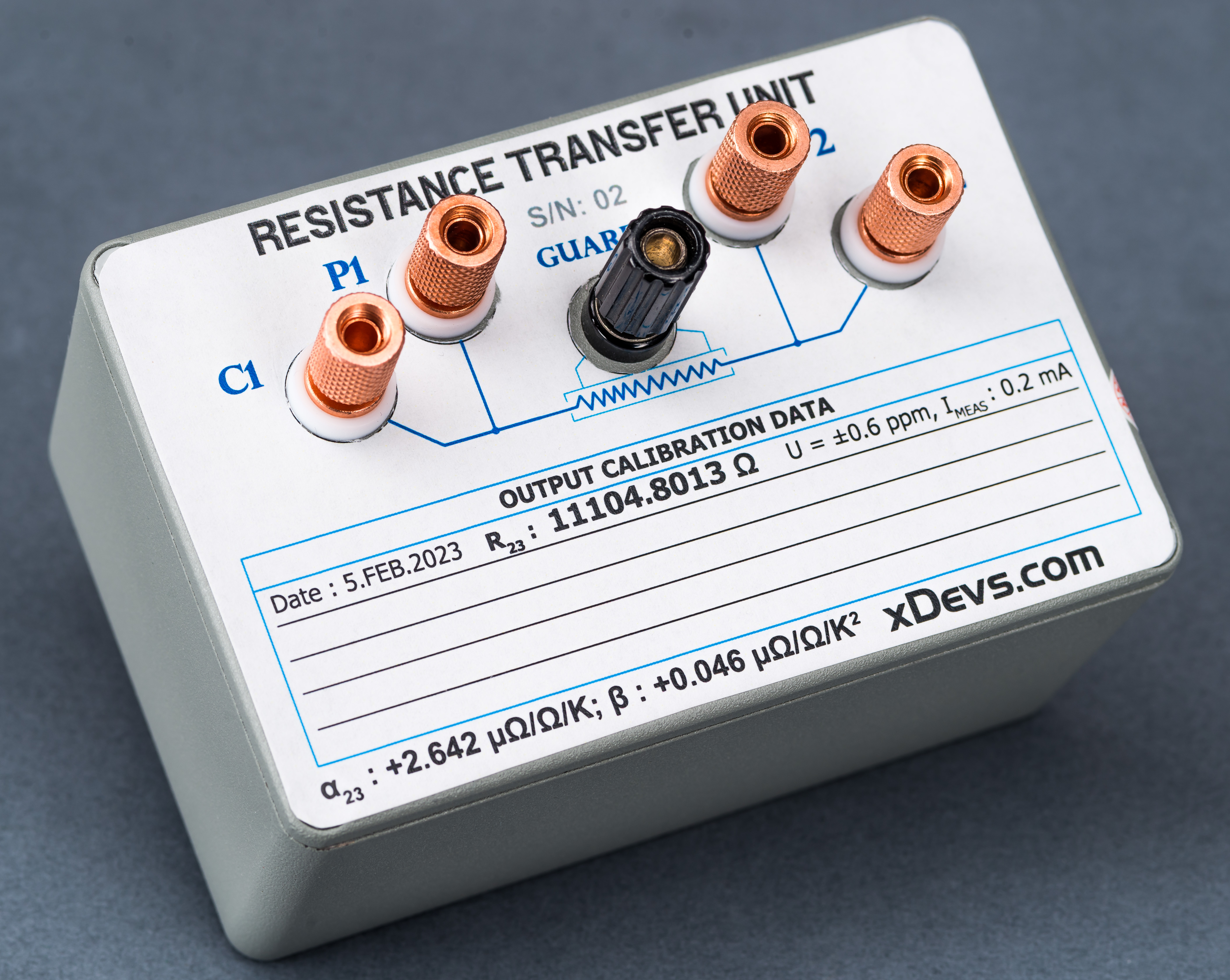
Image 13: Finished transfer standard with information label on top
Hopefully this box will arrive safe and intact to receiver. This article will be updated in future once more data is collected.

Image 14: Tempco calibration information label on bottom
Total cost of all parts used to build resistance standard shown above summarized here:
| Component | Quantity | Total price | Notes |
|---|---|---|---|
| Fluke P/N 311548 hermetic PWW resistor | 1 pcs | USD 7.4 | salvaged from Fluke 4250A |
| Low-thermal pure copper 5-way post | 4 pcs | USD 18 | |
| Brass 5-way post for guard terminal | 1 pcs | USD 3 | salvaged from ebay box |
| Metal enclosure Hammond 1590TGY | 1 pcs | USD 14.2 | |
| PTFE insulated wire | 15 cm | USD 3 | ebay special |
| Shipping to destination | regular post | USD 40 | included in package with E5810 |
Based on this we achieved the budget goals with total spending USD 85.6.
Discussion is very welcome thru comment section or at our own IRC chat server: irc.xdevs.com (standard port 6667, channel: #xDevs.com). Web-interface for access mirrored on this page.
Projects like this are born from passion and a desire to share how things work. Education is the foundation of a healthy society - especially important in today's volatile world. xDevs began as a personal project notepad in Kherson, Ukraine back in 2008 and has grown with support of passionate readers just like you. There are no (and never will be) any ads, sponsors or shareholders behind xDevs.com, just a commitment to inspire and help learning. If you are in a position to help others like us, please consider supporting xDevs.com’s home-country Ukraine in its defense of freedom to speak, freedom to live in peace and freedom to choose their way. You can use official site to support Ukraine – United24 or Help99. Every cent counts.
Modified: May 6, 2023, 9:15 p.m.