Contents
Intro
The R6452A is digital multimeter equipped with dual input A/D converter path that allow independent measurement of two signals. These multimeters are targeted for lab/ATE measurement and device testing by configuring as versatile measurement system. The channel A has measurement functions including DCV/DCI, ACV/ACI, two-wire resistance and frequency, while the channel B has DCV/DCI and ACI. There is also input port at the rear for Type K thermocouple temperature measurements.
R6452A have RS-232 interface and optional GPIB interface card to use in automated systems. The remote command language is not compliant with SCPI but using own protocol, similar to one used in other Advantest and older Keithley/HP equipment with simple letter commands.
Today R6452A meters are long obsolete and replaced by newer ADCMT 7352A model which have slightly better specifications, modern USB interface, but follows same design concept and targeted market.
Key features:
- Maximum display : 199999/199999 counts, 5½-digit resolution
- Measurement function : DCV, ACV, DCI, ACI, 2w-resistance, low-power resistance, Frequency, Diode, Continuity (A channel), DCV,DCI,ACI (B channel)
- Rear input: Thermocouple Type K temperature
- Sampling rate: FAST: 80 SPS, MED: 10 SPS, SLOW: 2.5 SPS
- Base range : 2 VDC
- DC voltage measurement best accuracy: 180ppm + 5 digits, Resolution: 1 µV (Ach/Bch)
- DC current measurement range : 200mA and 10A
- AC voltage measurement: 20Hz to 100kHz, 200mV – 700V ranges
- AC current measurement: 20Hz to 5kHz, 200mA and 10A ranges
- Interface : RS232, optional GPIB
- Form-factor : Half-width 19” 2U rack or benchtop
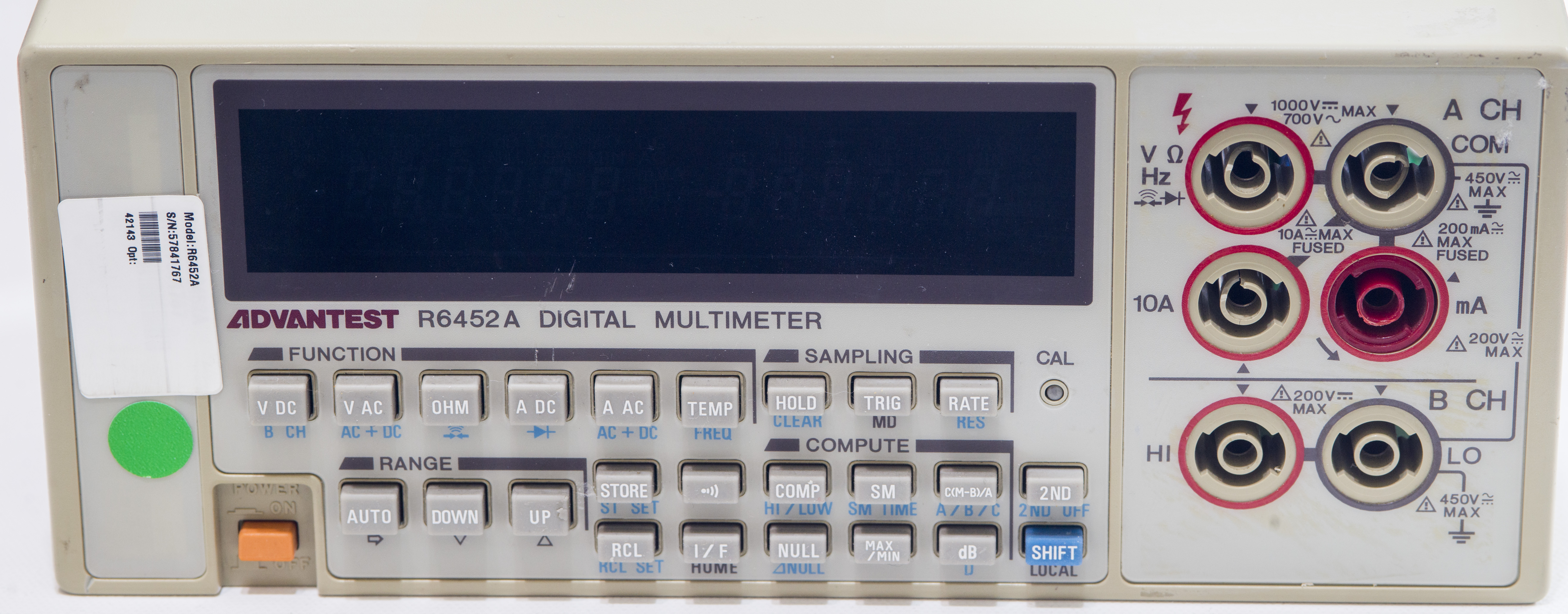
Image 1: Instrument front panel
Those input jacks that Advantest uses are super-fragile, and really one of the worst jacks on any instruments we ever used. Same poor jacks used in 8½-digit R6581 so it’s common for Advantest instruments. Red color fused current input jack accepts only maximum 200mA input, so be sure not to supply too much current, or you will have to find new 5mm 200mA glass fuse.
Buttons on the front panel are tiny, and some of the labels are rather cryptic, like SM or MD. Having no public manuals in English also does not help understanding meter operation.
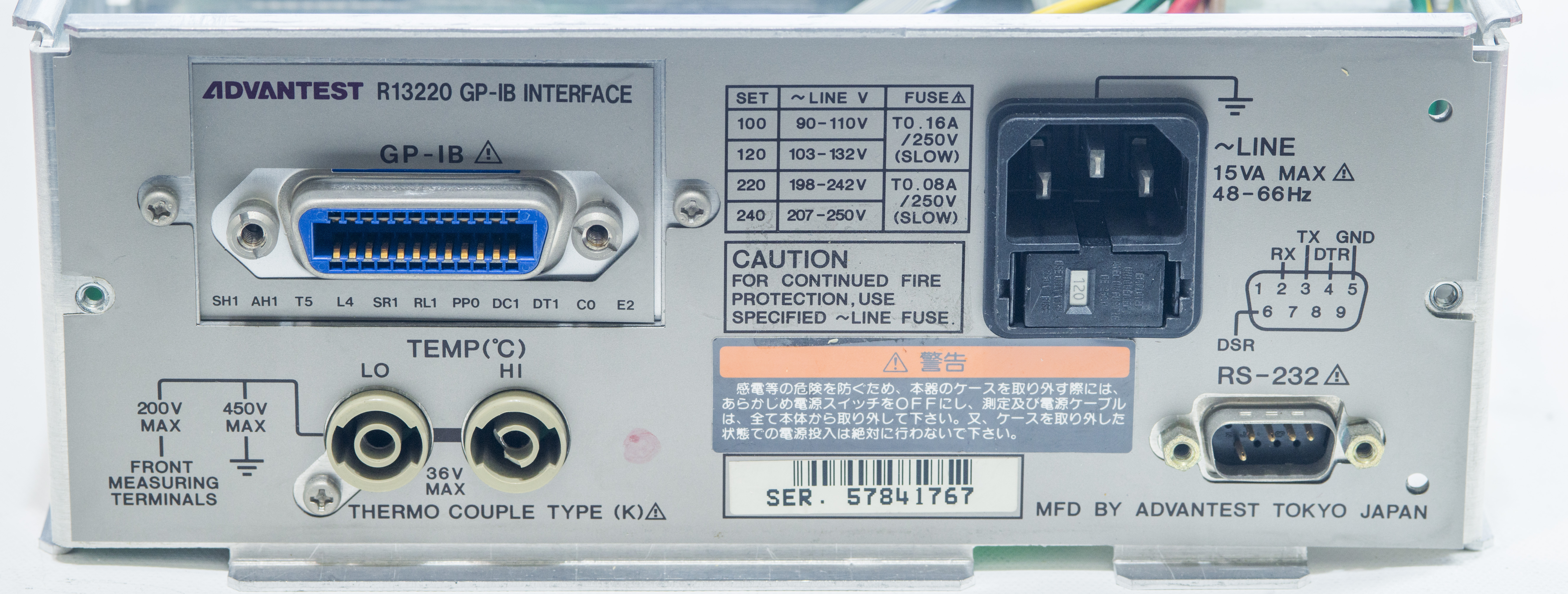
Image 2: Instrument rear panel
This particular instrument came with GPIB option, but standard unit supplied only with RS232 interface. Banana jacks on the rear dedicated for thermocouple connections only. Unit have mains voltage selector block combined with protection mains fuse. All Advantest instruments are manufactured in Japan.
Disclaimer
Redistribution and use of this article or any images or files referenced in it, in source and binary forms, with or without modification, are permitted provided that the following conditions are met:
- Redistributions of article must retain the above copyright notice, this list of conditions, link to this page (https://xdevs.com/article/r6452a/) and the following disclaimer.
- Redistributions of files in binary form must reproduce the above copyright notice, this list of conditions, link to this page (https://xdevs.com/article/r6452a/), and the following disclaimer in the documentation and/or other materials provided with the distribution, for example Readme file.
All information posted here is hosted just for education purposes and provided AS IS. In no event shall the author, xDevs.com site, or Advantest/ADCMT or any other 3rd party be liable for any special, direct, indirect, or consequential damages or any damages whatsoever resulting from loss of use, data or profits, whether in an action of contract, negligence or other tortuous action, arising out of or in connection with the use or performance of information published here.
If you willing to contribute or have interesting documentation to share regarding pressure measurements or metrology and electronics in general, you can do so by following these simple instructions.
Manuals and comparison to production standards
Advantest R6451A and R6452A datasheet with specs
Advantest R6451A and R6452A specifications, Japanese language
Advantest R6451A and R6452A GPIB command matrix, Japanese language
Advantest R6451A and R6452A operating manual, Japanese language
Advantest R6451A and R6452A catalog, Japanese language
Design and construction
Removing two screws and pulling cover off reveals simple assembly and internal design.
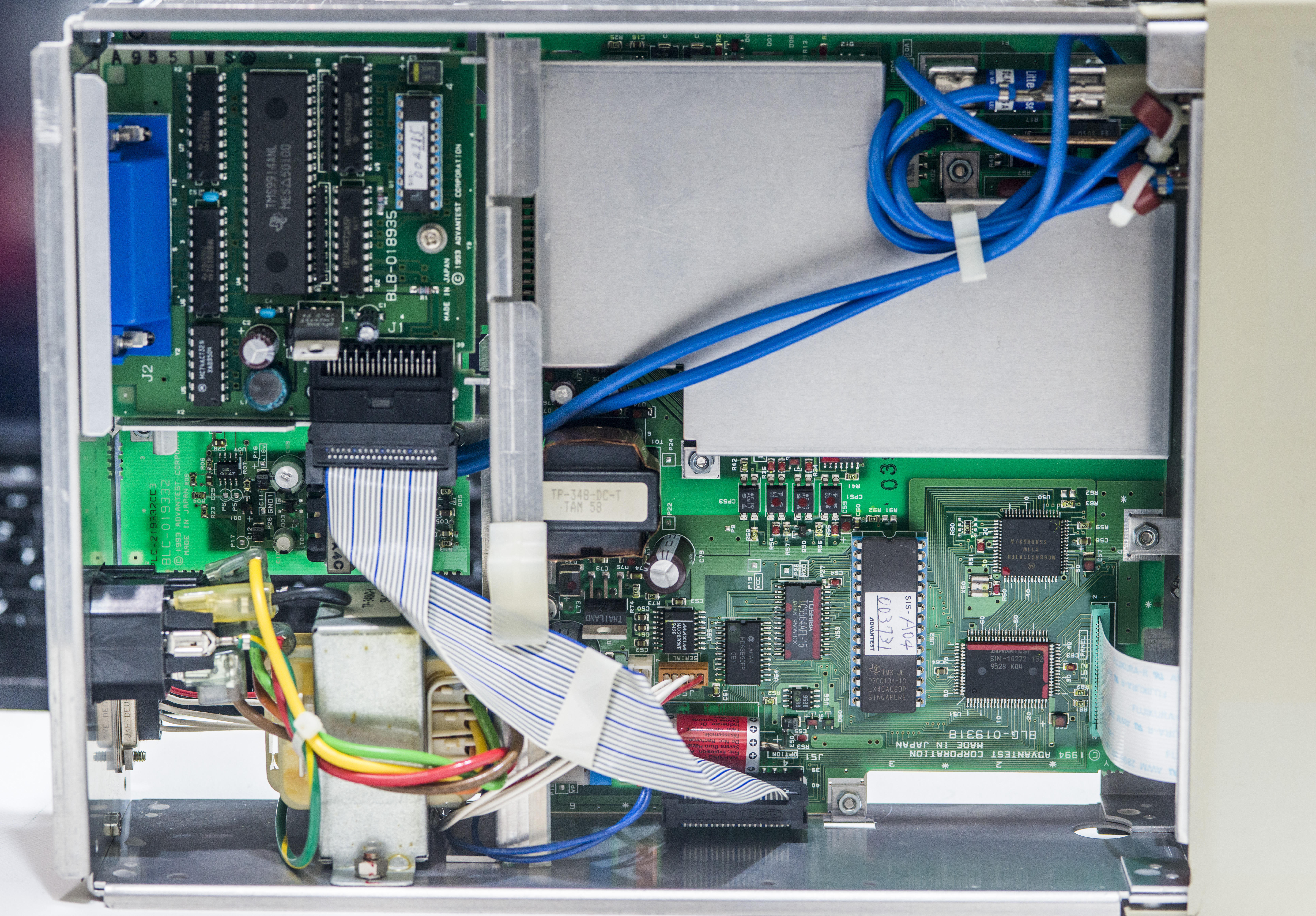
Image 3: Cover removed, top view
Blue cables going across the instrument are from input jacks. Ribbon cable carry digital signals between out-guard CPU section and GPIB interface board. Advantest have also other options for integrating R6452A into automated test jigs and even optional battery +12V pack to provide standalone operation. There are not that many 5½-digit DMMs that can be powered from battery, which can be useful in field work.
As typical with many other benchtop DMMs, this one also based around Motorola RISC processor, Motorola MC68HC11A to be precise. There is also custom Advantest ASIC next to it, with label SIM-10272-152 doing glue logic and front panel communication. Socketed firmware ROM is TMS27C010A-10 in ceramic DIP package.
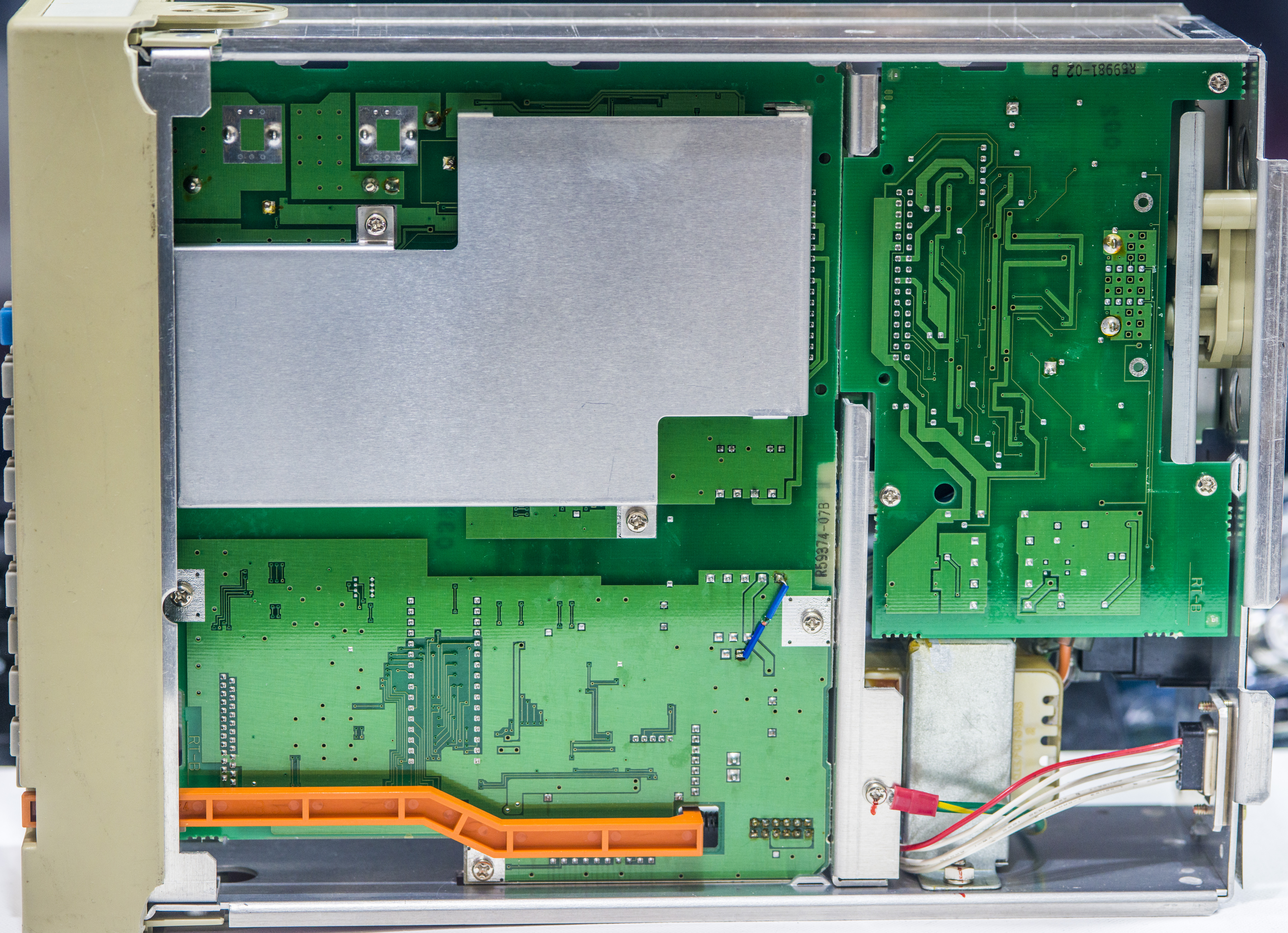
Image 4-5: Bottom side and input protection circuits
Other than little board mod diode, there are no components populated on the bottom side. One can find function switch relays and protection circuits near the input cable connections.
Image 6-7: Battery backup cell, front panel controller IC
RS232C level translation handled by Maxim MAX202CWE and UART controller Hitachi HD63B50P. Power regulator is located nearby, Linear LT1071CT. Date codes on IC suggest manufacturing date around 30th week of 1995. Battery help to retain SRAM contents with instrument readings and settings. Hopefully calibration data is stored in non-volatile memory, perhaps small SOIC-8 chip with 953B marking?
Image 8-9: FPC cable for front panel, firmware ROM chip
High-voltage DC/DC converter located on small daughter board right on the front panel PCB. This is required to generate proper levels for VFD screen operation.

Image 10-11: GPIB interface card
GPIB card using industry standard TMS9914 controller, some digital logic latches and 75160/75161 GPIB drivers. Small Lattice PAL/GAL device handle interrupts and dataflow.
Analog front-end section
Time to remove aluminum shield from analog section and study overall design.
Image 12: ADC ASIC and key features
ADC and control of the analog functions is implemented by custom Advantest ASIC, with label SIA-87841. There are lot of Linear LTC1050 chopper opamps around as well. Green epoxy resistor networks maintain accurate and stable ratios between various signals. One of these resistors used as high-voltage divider for 200V and 1kV ranges.
A/D converter input range is +/-2V. As result input resistance >1 GΩ is provided only for 200mV and 2V ranges, while higher ranges are using 10 MΩ input divider.
Image 13-14: LT1027 5V main reference
Image 15-16: TrueRMS converter circuit
AC RMS conversion is handled by widely known chip for the purpose, AD637. Same chip we can find in other benchtop meters, even high-performance type such as Keithley 2001 and Keithley 2002.
Image 17-18: Input terminals connections and current shunts
10A current input protected by high-quality HRC 15A Littelfuse fuse, placed on the socket for easy service. 0.1 Ω shunt is standing right next to the fuse, with smaller 1 Ω SMT-type shunt located under it. There are no low current ranges on this DMM, so current measurement function is rather simple.
Image 19-20: Isolation barrier
Interfacing between floating analog domain section and earth-referenced digital outguard section done thru four PC817 optocouplers. This means that communication between the processor and analog chipset is done serially thru some kind of SPI or UART-alike interface.

Image 21-22: Power transformers
Power is provided thru isolation transformer TP-348-DC-T. Mains transformer bears similar marking, with AC-T ending. Both transformers are unique to Advantest and custom made for this DMM.

Image 25-26: Film resistive networks
Image 23-24: Bottom side of the analog section, shields removed
There are no components on the back of the PCBA.
Thermocouple rear input assembly
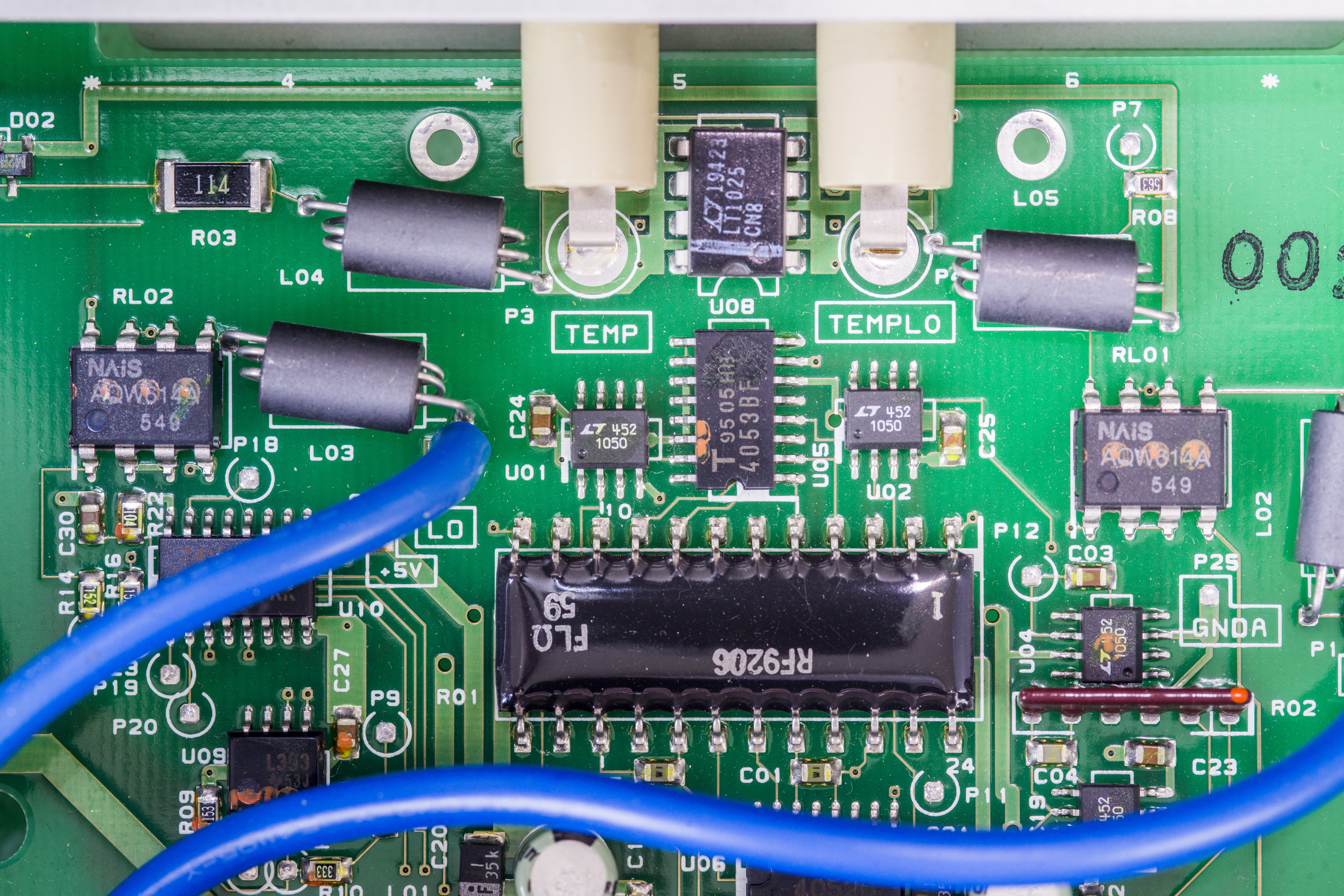
Image 27-28: Thermocouple input PCBA
Thermocouple input at the rear using own PCBA, interconnected thru DIN-type connector with mainboard. Input terminals have proper thermocouple cold-junction compensator LT1025, that provide 0.5 °C initial accuracy for correct Type K probe measurements. There are four more LTC1050 chopper opamps, large black epoxy resistor network and few analog 4052/4053 switches to route signal for ADC.
NAIS AQW614A PhotoMOS provide signal protection for the sensitive inputs.
Firmware
Firmware ROM dumps from single TMS27C010A ROM, read by general purpose ROM programmer.
| Firmware version | Binary file | Checksum |
|---|---|---|
| Model R6452A A04, SIS-003731, U52 ROM | Binary file | CHK:0×0018A8A5F |
Calibration testing
To test performance and perform calibration we will utilize what is available in lab:
- Fluke 5720A for DCV, ACV, DCI, ACI and Resistance tests. Calibrated February 10, 2019
- Fluke 5720A + 5725A amplifier for 10A DCI and ACI tests. Calibrated February 10, 2019
- Keysight 3458A as reference standard for calibration verification
- Wavetek 4920M as reference meter for calibration verification
- Set of shielded Fluke 5440A-7002 cables with copper low-thermal dual banana connectors
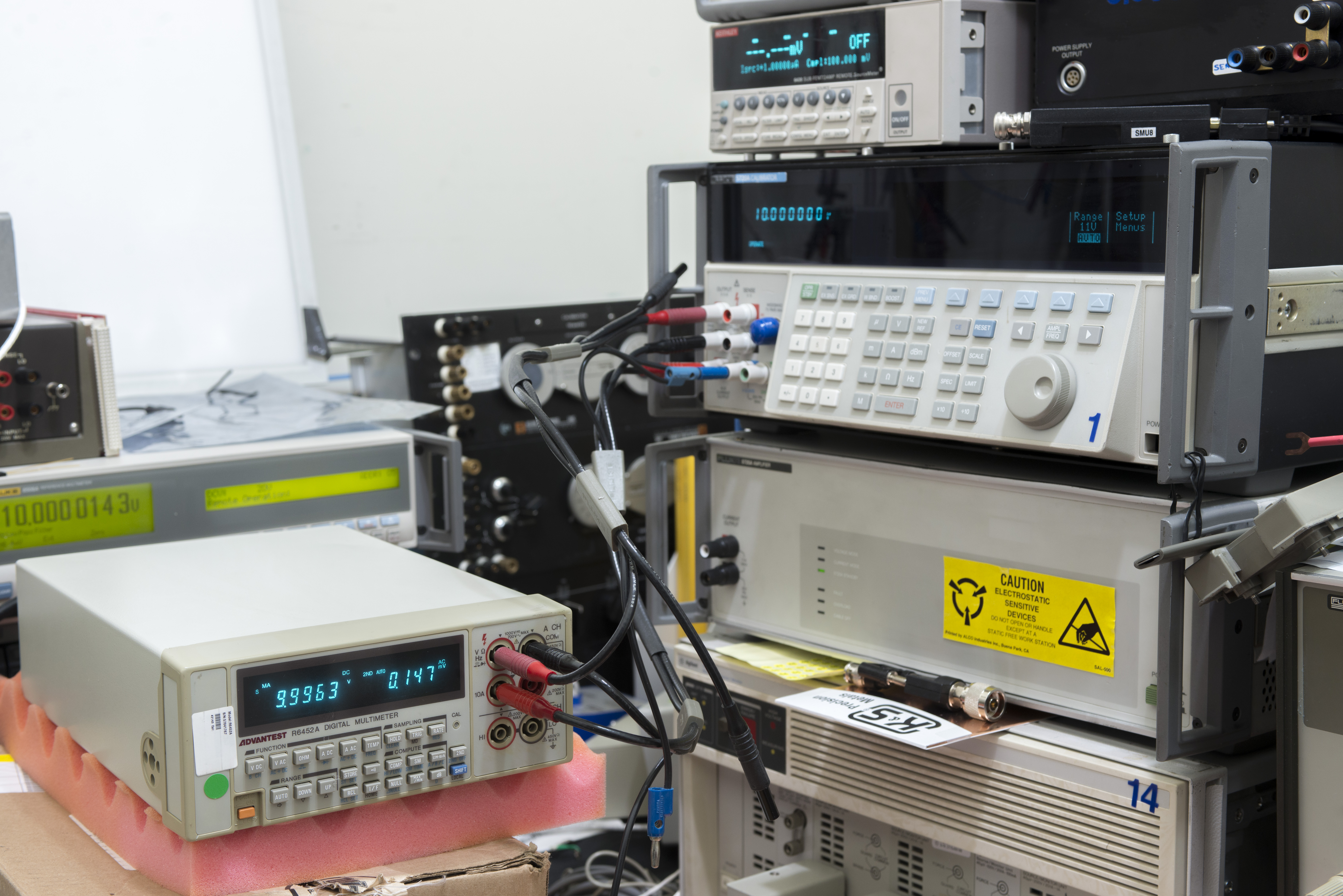
Image 29: R6452A during calibration, showing connections to Fluke 5720A
Calibrator was artifact calibrated to reference standards just a 19 days ago, but at accuracy levels of R6452A that is completely unnecessary. Even annual specifications of Fluke 5720A provide good TUR to meet all specifications of this DMM so the calibrator tested just to provide good confidence in results. Ambient temperature was kept at +23 °C ±1 °C.
No adjustments were performed for this DMM and the original calibration date/time is unknown.
| Test point | Measured value | Source uncertainty, ppm | DUT spec, ppm | Deviation | Result, %/spec | TUR |
|---|---|---|---|---|---|---|
| -19 mV | -0.018987 | 25.05 | 496 ppm | -684 ppm | 138.0% | 5.4 |
| -10 mV | -0.010002 | 44.00 | 780 ppm | 200 ppm | 25.6% | 9.5 |
| +10 mV | 0.009991 | 44.00 | 780 ppm | -900 ppm | 115.4% | 17.7 |
| +19 mV | 0.018988 | 25.05 | 496 ppm | -632 ppm | 127.4% | 19.8 |
| -190 mV | -0.18997 | 6.11 | 212 ppm | -158 ppm | 74.6% | 34.7 |
| -100 mV | -0.10000 | 8.00 | 240 ppm | 0 ppm | 0.0% | 30.0 |
| +100 mV | 0.09993 | 8.00 | 240 ppm | -700 ppm | 291.7% | 30.0 |
| +190 mV | 0.18990 | 6.11 | 212 ppm | -526 ppm | 248.8% | 34.7 |
| -1.9 V | -1.8996 | 3.37 | 206 ppm | -211 ppm | 102.0% | 61.3 |
| -1.0 V | -1.0000 | 3.70 | 230 ppm | 0 ppm | 0.0% | 62.2 |
| +1.0 V | 0.9993 | 3.70 | 230 ppm | -700 ppm | 304.3% | 62.2 |
| +1.9 V | 1.8990 | 3.37 | 206 ppm | -526 ppm | 255.1% | 61.3 |
| -19 V | -18.997 | 2.21 | 206 ppm | -158 ppm | 76.5% | 93.3 |
| -10 V | -10.000 | 2.25 | 230 ppm | 0 ppm | 0.0% | 102.2 |
| +10 V | 9.9963 | 2.25 | 230 ppm | -370 ppm | 160.9% | 102.2 |
| +19 V | 18.990 | 2.21 | 206 ppm | -526 ppm | 255.1% | 93.3 |
| -190 V | -189.98 | 3.21 | 206 ppm | -105 ppm | 51.0% | 64.3 |
| -100 V | -100.01 | 3.40 | 230 ppm | 100 ppm | 43.5% | 67.6 |
| +100 V | 99.93 | 3.40 | 230 ppm | -700 ppm | 304.3% | 67.6 |
| +190 V | 189.89 | 3.21 | 206 ppm | -579 ppm | 280.6% | 64.3 |
| -500 V | -499.88 | 4.80 | 280 ppm | -240 ppm | 85.7% | 58.3 |
| -1000 V | -999.73 | 4.40 | 230 ppm | -270 ppm | 117.4% | 52.3 |
| +1000 V | 999.63 | 4.40 | 230 ppm | -370 ppm | 160.9% | 52.3 |
| +500 V | 499.79 | 4.80 | 280 ppm | -420 ppm | 150.0% | 58.3 |
From DC Voltage test results meter is unable to meet it’s specifications and need to be adjusted.
| Test point | Measured value | Source uncertainty, ppm | DUT spec, ppm | Deviation | Result, %/spec | TUR |
|---|---|---|---|---|---|---|
| 10.000322 Ω | 9.99000 | 23 | 1000 | -1032 ppm | -103.2% | 43.5 |
| 19.000006 Ω | 18.996 | 23 | 716 | -211 ppm | -29.5% | 31.1 |
| 100.00319 Ω | 100.013 | 10 | 460 | 98 ppm | 21.3% | 46.0 |
| 189.99882 Ω | 189.932 | 10 | 432 | -352 ppm | -81.5% | 43.2 |
| 1000.0099 Ω | 999.78 | 8 | 250 | -230 ppm | -92.0% | 31.2 |
| 1900.0239 Ω | 1899.52 | 8 | 226 | -265 ppm | -117.2% | 28.3 |
| 9999.786 Ω | 9998.9 | 8 | 250 | -89 ppm | -35.4% | 31.3 |
| 18999.392 Ω | 18997.6 | 9 | 226 | -94 ppm | -41.7% | 25.1 |
| 99994.64 Ω | 99980 | 9 | 250 | -146 ppm | -58.6% | 27.8 |
| 189988.81 Ω | 189962 | 9 | 226 | -141 ppm | -62.4% | 25.1 |
| 999980.6 Ω | 999660 | 16 | 360 | -321 ppm | -89.1% | 22.5 |
| 1899967 Ω | 1899860 | 17 | 332 | -56 ppm | -17.0% | 19.5 |
| 9999029 Ω | 9995400 | 33 | 2100 | -363 ppm | -17.3% | 63.6 |
| 18998410 Ω | 18991200 | 43 | 2053 | -380 ppm | -18.5% | 47.7 |
| 100007070 Ω | 99960000 | 100 | 20000 | -471 ppm | -2.4% | 200.0 |
Resistance results are not as bad as DC Voltage, however 2KΩ range could use some adjustment help.
| Test point | Measured value | Source uncertainty, ppm | DUT spec, ppm | Deviation | Result, %/spec | TUR |
|---|---|---|---|---|---|---|
| -19 mA | -0.019001 | 39.2 | 1316 | 53 ppm | 4.0% | 33.6 |
| -10 mA | -0.010003 | 43.0 | 1600 | 300 ppm | 18.7% | 37.2 |
| +10 mA | 0.009990 | 43.0 | 1600 | -1000 ppm | -62.5% | 37.2 |
| +19 mA | 0.018989 | 39.2 | 1316 | -579 ppm | -44.0% | 33.6 |
| -190 mA | -0.189951 | 53.0 | 1032 | -258 ppm | -25.0% | 19.5 |
| -100 mA | -0.099975 | 49.2 | 1060 | -250 ppm | -23.6% | 21.5 |
| +100 mA | 0.099967 | 49.2 | 1060 | -330 ppm | -31.1% | 21.5 |
| +190 mA | 0.189938 | 53.0 | 1032 | -326 ppm | -31.6% | 19.5 |
| -1.9 A | -1.8992 | 73.1 | 1316 | -421 ppm | -32.0% | 18.0 |
| -1.0 A | -1.0000 | 85.0 | 1600 | 0 ppm | 0.0% | 18.8 |
| +1.0 A | 0.9986 | 85.0 | 1600 | -1400 ppm | -87.5% | 18.8 |
| +1.9 A | 1.8981 | 73.1 | 1316 | -1000 ppm | -76.0% | 18.0 |
| -5 A | -4.9977 | 372.7 | 1120 | -460 ppm | -41.1% | 3.0 |
| -10 A | -9.9972 | 372.7 | 1060 | -280 ppm | -26.4% | 2.8 |
| +10 A | 9.9962 | 372.7 | 1060 | -380 ppm | -35.8% | 2.8 |
| +5 A | 4.9979 | 372.7 | 1120 | -420 ppm | -37.5% | 3.0 |
To our surprise, DC current function is still in spec, even when measuring current at mere 5% of the scale!
| Test point | Measured value | Source uncertainty, ppm | DUT spec, ppm | Deviation | Result, %/spec | TUR |
|---|---|---|---|---|---|---|
| 10 mV, 20 Hz | 0.010028 | 312.27 | 41000 | 2800 ppm | 6.8% | 131.3 |
| 10 mV, 1 kHz | 0.010062 | 312.27 | 22000 | 6200 ppm | 28.2% | 70.5 |
| 100 mV, 20 Hz | 0.099360 | 121.36 | 9500 | -6400 ppm | -67.4% | 78.3 |
| 100 mV, 1 kHz | 0.099785 | 121.36 | 4000 | -2150 ppm | -53.8% | 33.0 |
| 190 mV, 20 Hz | 0.189110 | 121.36 | 7842 | -4684 ppm | -59.7% | 64.6 |
| 190 mV, 1 kHz | 0.189916 | 121.36 | 3053 | -442 ppm | -14.5% | 25.2 |
| 190 mV, 10 kHz | 0.189955 | 121.36 | 3053 | -237 ppm | -7.8% | 25.2 |
| 190 mV, 20 kHz | 0.189843 | 121.36 | 3053 | -826 ppm | -27.1% | 25.2 |
| 190 mV, 100 kHz | 0.186016 | 590.91 | 42632 | -20968 ppm | -49.2% | 72.1 |
| 1.0 V, 20 Hz | 0.99390 | 49.55 | 9500 | -6100 ppm | -64.2% | 191.7 |
| 1.0 V, 60 Hz | 0.99758 | 49.55 | 4000 | -2420 ppm | -60.5% | 80.7 |
| 1.0 V, 1 kHz | 0.99786 | 49.55 | 4000 | -2140 ppm | -53.5% | 80.7 |
| 1.0 V, 10 kHz | 0.99808 | 49.55 | 4000 | -1920 ppm | -48.0% | 80.7 |
| 1.0 V, 20 kHz | 0.99855 | 49.55 | 4000 | -1450 ppm | -36.2% | 80.7 |
| 1.0 V, 100 kHz | 1.0146 | 138.18 | 45000 | 14600 ppm | 32.4% | 325.7 |
| 1.9 V, 20 Hz | 1.8917 | 49.55 | 7842 | -4368 ppm | -55.7% | 158.3 |
| 1.9 V, 45 Hz | 1.8977 | 49.55 | 7842 | -1211 ppm | -15.4% | 158.3 |
| 1.9 V, 1 kHz | 1.89932 | 49.55 | 3053 | -358 ppm | -11.7% | 61.6 |
| 1.9 V, 10 kHz | 1.89986 | 49.55 | 3053 | -74 ppm | -2.4% | 61.6 |
| 1.9 V, 20 kHz | 1.90082 | 49.55 | 3053 | 432 ppm | 14.1% | 61.6 |
| 1.9 V, 100 kHz | 1.93305 | 138.18 | 42632 | 17395 ppm | 40.8% | 308.5 |
| 10.0 V, 20 Hz | 9.9482 | 48.18 | 9500 | -5180 ppm | -54.5% | 197.2 |
| 10.0 V, 60 Hz | 9.9825 | 48.18 | 4000 | -1750 ppm | -43.8% | 83.0 |
| 10.0 V, 1 kHz | 9.987 | 48.18 | 4000 | -1300 ppm | -32.5% | 83.0 |
| 10.0 V, 10 kHz | 9.9875 | 48.18 | 4000 | -1250 ppm | -31.2% | 83.0 |
| 10.0 V, 20 kHz | 9.9865 | 48.18 | 4000 | -1350 ppm | -33.8% | 83.0 |
| 10.0 V, 100 kHz | 9.9667 | 121.36 | 45000 | -3330 ppm | -7.4% | 370.8 |
| 19 V, 60 Hz | 18.9815 | 48.18 | 3053 | -974 ppm | -31.9% | 63.4 |
| 19 V, 1 kHz | 18.9905 | 48.18 | 3053 | -500 ppm | -16.4% | 63.4 |
| 19 V, 10 kHz | 18.9915 | 48.18 | 3053 | -447 ppm | -14.7% | 63.4 |
| 19 V, 20 kHz | 18.9912 | 48.18 | 42632 | -463 ppm | -1.1% | 884.8 |
| 19 V, 100 kHz | 18.971 | 121.36 | 3053 | -1526 ppm | -50.0% | 25.2 |
| 100 V, 60 Hz | 99.891 | 60.18 | 4000 | -1090 ppm | -27.2% | 66.5 |
| 100 V, 1 kHz | 99.942 | 60.18 | 4000 | -580 ppm | -14.5% | 66.5 |
| 100 V, 10 kHz | 99.943 | 60.18 | 4000 | -570 ppm | -14.3% | 66.5 |
| 100 V, 20 kHz | 99.936 | 60.18 | 4000 | -640 ppm | -16.0% | 66.5 |
| 100 V, 100 kHz | 99.539 | 173.64 | 45000 | -4610 ppm | -10.2% | 259.2 |
| 190 V, 60 Hz | 189.817 | 60.18 | 3053 | -963 ppm | -31.6% | 50.7 |
| 190 V, 1 kHz | 189.910 | 60.18 | 3053 | -474 ppm | -15.5% | 50.7 |
| 190 V, 10 kHz | 189.911 | 60.18 | 3053 | -468 ppm | -15.3% | 50.7 |
| 190 V, 20 kHz | 189.900 | 60.18 | 3053 | -526 ppm | -17.2% | 50.7 |
| 190 V, 100 kHz | 189.312 | 173.64 | 42632 | -3621 ppm | -8.5% | 245.5 |
| 300 V, 60 Hz | 299.690 | 78.64 | 8667 | -1033 ppm | -11.9% | 110.2 |
| 300 V, 1 kHz | 299.790 | 78.64 | 8667 | -700 ppm | -8.1% | 110.2 |
| 300 V, 10 kHz | 299.800 | 78.64 | 8667 | -667 ppm | -7.7% | 110.2 |
| 700 V, 60 Hz | 699.270 | 78.64 | 4857 | -1043 ppm | -21.5% | 61.8 |
| 700 V, 1 kHz | 699.590 | 78.64 | 4857 | -586 ppm | -12.1% | 61.8 |
AC Voltage is also okay, meeting specs with decent margin on most of the points.
| Test point | Measured value | Source uncertainty, ppm | DUT spec, ppm | Deviation | Result, %/spec | TUR |
|---|---|---|---|---|---|---|
| 19 mA, 60 Hz | 0.018971 | 138.18 | 16526 | -1526 ppm | -9.2% | 119.6 |
| 19 mA, 1 kHz | 0.018988 | 138.18 | 60526 | -632 ppm | -1.0% | 438.0 |
| 100 mA, 60 Hz | 0.099745 | 133.64 | 8000 | -2550 ppm | -31.9% | 59.9 |
| 100 mA, 1 kHz | 0.099823 | 133.64 | 52000 | -1770 ppm | -3.4% | 389.1 |
| 100 mA, 5 kHz | 0.099874 | 133.64 | 8000 | -1260 ppm | -15.8% | 59.9 |
| 190 mA, 1 kHz | 0.189925 | 133.64 | 51053 | -395 ppm | -0.8% | 382.0 |
| 1.0 A, 60 Hz | 0.996600 | 308.18 | 26000 | -3400 ppm | -13.1% | 84.4 |
| 1.0 A, 1 kHz | 0.999000 | 308.18 | 70000 | -1000 ppm | -1.4% | 227.1 |
| 1.9 A, 60 Hz | 1.884500 | 308.18 | 16526 | -8158 ppm | -49.4% | 53.6 |
| 1.9 A, 1 kHz | 1.888400 | 308.18 | 60526 | -6105 ppm | -10.1% | 196.4 |
| 10 A, 60 Hz | 9.972500 | 385.45 | 8000 | -2750 ppm | -34.4% | 20.8 |
| 10 A, 1 kHz | 9.995200 | 385.45 | 52000 | -480 ppm | -0.9% | 134.9 |
AC Current show no problems either.
DCV linearity verification
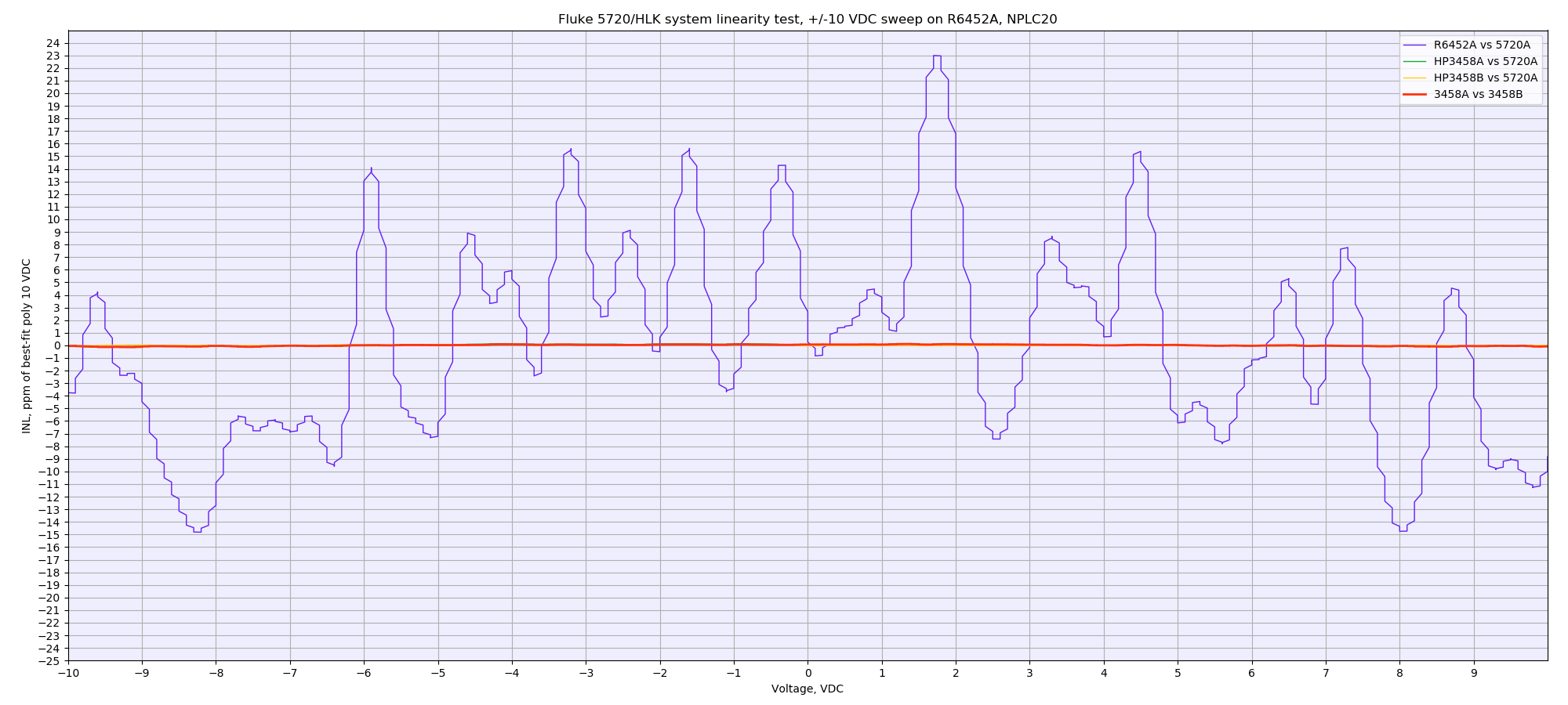
Image 30: R6452A 20VDC range linearity test, using -11 to +11V DC
There is no linearity specification in the datasheet, so we can assume this spec to be ±25 ppm based on the counts error specified for the range. Ideally we should have tested 2V range, but since typical precision application commonly used 10V, tested was performed using -11.0 to +11.0 sweep. Keysight 3458A INL is essentially invisible zero on the scale of R6452A DMM.
Summary
Stay tuned and let us know your feedback! Discussion about this article and related stuff is welcome in comment section or at our own IRC chat server: irc.xdevs.com (standard port 6667, channel: #xDevs.com). Web-interface for access mirrored on this page.
Projects like this are born from passion and a desire to share how things work. Education is the foundation of a healthy society - especially important in today's volatile world. xDevs began as a personal project notepad in Kherson, Ukraine back in 2008 and has grown with support of passionate readers just like you. There are no (and never will be) any ads, sponsors or shareholders behind xDevs.com, just a commitment to inspire and help learning. If you are in a position to help others like us, please consider supporting xDevs.com’s home-country Ukraine in its defense of freedom to speak, freedom to live in peace and freedom to choose their way. You can use official site to support Ukraine – United24 or Help99. Every cent counts.
Modified: March 3, 2019, 9:47 a.m.