Contents
- Intro
- Disclaimer
- Exterior
- Initial inspection and basic disassembly
- Service information and downloads
- Internal structure and block details
- Overall Keithley 2001 repair procedure
- Unit #1 repair section
- Unit #1 calibration section
- Unit #2 repair section
- Unit #2 calibration section
- Unit #7 repair section
- Unit #7 calibration section
- Infrared thermal images
- Memory options
- Performance verification
- Conclusion
Intro
The Model 2001 from Keithley (today part of Tektronix) is a high performance 7½-digit bench digital multimeter, which share same appearance to other Keithley 2xxx series measuring/sourcing tools and designed to fit into standard 19” rack. It have half-width size, allowing two units to be installed side by side. Such format perfectly fits main purpose of system meters, which is often a choice of use for production testing/validation and research. The build quality of the hardware is pretty good and construction is robust enough to withstand most of generic usage as well. Setting up the 2001 is straight forward, it’s easy to use right from power on, and does not need reading operator manual to perform most of usual functions.
Model 2001 is already replaced by Tektronix with far more capable DMM7510 with modern user interface and very different internal design. DMM7510 is available from Tektronix for 8340 CAD. There is even twin DMM7512 variant in 1U rackmount form-factor tailored for automated test racks and system integration. As these new instruments emerge on market like DMM7510 or competitor Keysight 34470A there are still very limited number of DMMs can archive specs which Model 2001 have, specially considering relatively affordable (often less than 1000$ USD) offerings for these meters on second market.
Key specs and features of Model 2001 multimeter are:
- 18 ppm base DCV Accuracy
- High Throughput, up to 2000 Readings per Second
- 10nV Sensitivity
- Solid State Protection to 1600V
- 1µsec Spike Detection
- 2µsec Trigger Latency
- AC Crest Factor Display
- 10-Channel Scanner Option
- Support for rare Keithley 1801 nanovolt amplifier option
- In-Circuit Current to 12 A
- 4½, 5½, 6½, or 7½ Digits
- 2 MHz AC Voltage Measurement with Peak, Average, & True RMS AC Measurements
- Multiple Measurement Displays with bar Graph Display feature
- Frequency Measurements up to to 15MHz
- RTD and Thermocouple Measurements
- SCPI Commands, IEEE 488.2 Compatible
- Trigger-Link for syncronization
- 128kB Reading Memory Option
- Hi-Lo Limits with Digital Outputs
In this repair article we will go with overview, tests for broken component/blocks of few old used units we have, as well as cover repair methodology and service information notes. This hopefully will enable owners of Model 2001 meters to fix their damaged instruments and continue to enjoy their performance for few more decades. Model 2001 was developed quite long time ago (around 1990-1992) and is already obsolete It took more than 20 years till release of recent 7½-digit refresh unit, Model DMM7510. While new DMM7510 provide new fancy interface, in few features of old-school Model 2001 is still superior such as provided scan-card option possibility.
Disclaimer
Redistribution and use of this article or any files referenced in it, in source and binary forms, with or without modification, are permitted provided that the following conditions are met:
- Redistributions of article must retain the above copyright notice, this list of conditions, link to this page (https://xdevs.com/article/kei2001/) and the following disclaimer.
- Redistributions of files in binary form must reproduce the above copyright notice, this list of conditions, link to this page (https://xdevs.com/article/kei2001/), and the following disclaimer in the documentation and/or other materials provided with the distribution, for example Readme file.
All information posted here is hosted just for education purposes and provided AS IS. In no event shall the author, xDevs.com site, or any other 3rd party, including Keithley Instruments or Tektronix be liable for any special, direct, indirect, or consequential damages or any damages whatsoever resulting from loss of use, data or profits, whether in an action of contract, negligence or other action, arising out of or in connection with the use or performance of information published here.
If you willing to contribute or add your experience regarding any test instruments or provide any extra information, such as firmware dumps, internal photographs, you can do so following these simple instructions
Service information and downloads
Most important first, schematics for repairs:
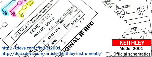
Before we start with repairs, here are official manuals including schematics:
Model 2001 and Model 2002 Datasheet 2024
Model 2001 and Model 2002 Datasheet
Model 2001, Specifications, Rev.L, Aug 2023
Model 2001, Specifications, Rev.H, Feb 2009
Model 2001, Quick Reference Guide, Rev.B
Model 2001, Operator’s Manual, Rev.K, Aug 2010
Model 2001M, Operator’s Manual, Rev.K, Mar 2011
Model 2001 Calibration Manual, Rev.H, Sep 2023
Model 2001M, Calibration Manual, Rev.H, Mar 2011
Model 2001, Calibration Manual, Rev.G, May 2004
Model 2001M, Average RMS B16 Firmware Upgrade for Model 2001-M Release Notes
Model 2001, Model 2001-SCAN Scanner Card Instruction Manual, Rev.C, Jun 1998
Model 2001, Model 2001-TCSCAN Scanner Card Instruction Manual, Rev.B, Jan 1997
Model 2001, Scanner Option 2001-SCAN Specifications, Rev.B
Model 2001 and Model 7001 / 7002 Switch System, software
Model 2001, Repair Manual, Rev.D, Sep 2023
Model 2001, Repair Manual, Rev.C, May 2011
Model 2001, Repair Manual, Rev.B, Feb 1996
Model 2001, Repair Manual Addendum, Rev.C, Mar 2011, BOM
Model 2001, Repair Manual Addendum Schematics part 1, Rev.C, Mar 2011
Model 2001, Repair Manual Addendum Schematics part 2, Rev.C, Mar 2011
Model 2001 3D CAD Model in STEP file
Unofficial schematics , reverse engineering from Rev.L PCB
This schematics provided as is, reverse engineered. Not complete, Use with caution.
PDF-format schematics, 21 January 2014
A/D module schematics and signal measurements
Firmware dumps
| Firmware version | Combined binary | ODD ROM | EVEN ROM |
|---|---|---|---|
| Model 2001 A05 | 2001-A05 ROM binary LEND | ||
| Model 2001 A06 | 2001-A06 ROM binary LEND | ||
| Model 2001 A08 (Latest for A-verison, 4Mbit) | 2001-A08 ROM binary LEND | ||
| Model 2001 B06 | 2001-B06 LEND | 2001-803-B06 | 2001-804-B06 |
| Model 2001 B07, Version 13.1, Feb 4 10:18:36 EST 1994 | 2001-B07 LEND | 2001-803-B07 | 2001-804-B07 |
| Model 2001 B08, Version 17.1, Sep 6 16:12:29 EDT 1994 | 2001-B08 ROM Binary 2001-B08 LEND | 2001-803-B08 | 2001-804-B08 |
| Model 2001 B09, Version 23.1, Jun 12 12:17:07 EDT 1995 | 2001-B09 LEND | 2001-803-B09 | 2001-804-B09 |
| Model 2001 B10, Version 29.1, Feb 5 09:56:39 EST 1996 | 2001-B10 ROM Binary 2001-B10 LEND | 2001-803-B10 | 2001-804-B10 |
| Model 2001 B11, Version 35.1, May 6 15:15:32 EDT 1998 | 2001-B11 LEND | 2001-803-B11 | 2001-804-B11 |
| Model 2001 B13, Version 45.1, Apr 29 13:10:54 EDT 1999 | 2001-B13 LEND | 2001-803-B13 | 2001-804-B13 |
| Model 2001 B15, Version 54.1, Oct 23 08:57:18 EDT 2000 | 2001-B15 ROM Binary 2001-B15 LEND | 2001-803-B15 | 2001-804-B15 |
| Model 2001 B16, Version 57.1, Sep 8 14:51:30 EDT 2003 | 2001-B16 LEND | 2001-803-B16 | 2001-804-B16 |
| Model 2001M B17, Version 7.1, Nov 5 08:32:34 EST 2009 | 2001M-B17 LEND | 2001M-803-B17 | 2001M-804-B17 |
Older A-version (single 4Mbit ROM, no support Keithley 1801 nV preamp). B-version firmwares are used on Rev.K digital PCB with two 4MBit ROMs (even and odd bytes).
Key differences of B-version code:
- Supports Keithley Model 1801 nV preamp
- Supports internal Keithley Model 2031 phase measurement extension module
- Supports internal Keithley Model 2051 TC-OHM extension module
- Supports SPRTD and Thermocouple Type N sensors from B11 version (same as Keithley 2002 A09+).
Do not flash little endian binaries (LEND) into ROM, they will not work. Motorola 68000 is using big-endian encoding, with LSB half first. Little-endian binaries are available only for firmware analysis purpose. To convert them simple python app was used:
# xDevs.com Firmware endian conversion app BE -> LE1
# https://xdevs.com/fix/kei2001

import os

with open('Input_BE.BIN','rb') as a:
    with open('Output_LE.bin','wb') as x:
        for cnt in range(0, 524288):
            y = a.read(1)
            z = a.read(1)
            x.write ("%s%s" % (z, y) )
Based on binary comparison, firmware since version B11 (similar to Keithley 2002’s A09) added support for Type N thermocouples and SPRTD which was absent in A06, at least based on text strings difference. Also there is new extra strings – HPR.HPRECISION, ISN, A4, B4, A7, B7, C7, RZERO, RZER. It seems that A06 have also only 9 settings profiles (SAV0 to SAV8), while A09 and later have 10 (SAV0 to SAV9).
HPR, RZERo, SPRTD string is related to GPIB readings format and RTD temperature sensors, as explained in User’s manual:
SPRTD (RZERO, A4, B4, A7, B7, C7) settings are explained on page 233-234 as well.
One more person mentioned in A09’s credits: Justin Noble
I do not know what is difference between other versions, as there are no public revision logs available.
Combined binary images were merged using simple python tool:
# xDevs.com Firmware combine tool
# https://xdevs.com/fix/kei2001

import os

with open('2002_804_a06_even_0150fa76.bin','rb') as a:
    with open('2002_803_a06_odd_01c9ab74.bin','rb') as b:
        with open('K2002_A06_FULL.bin','wb') as x:
            for cnt in range(0, 1048576):
                x.write ("%s%s" % (a.read(1),b.read(1) ) )
So likely firmware version B11 changeset to older B09 is next:
- Support for Type N thermocouples
- Support for SPRTD which was absent in A06
- New format setting : HPR (HPRECISION)
- Unknown command ISN?
- Coefficient settings for SPRTD: A4, B4, A7, B7, C7
- RTD custom user setting RZERO, RZER, to set resistance at 0°C
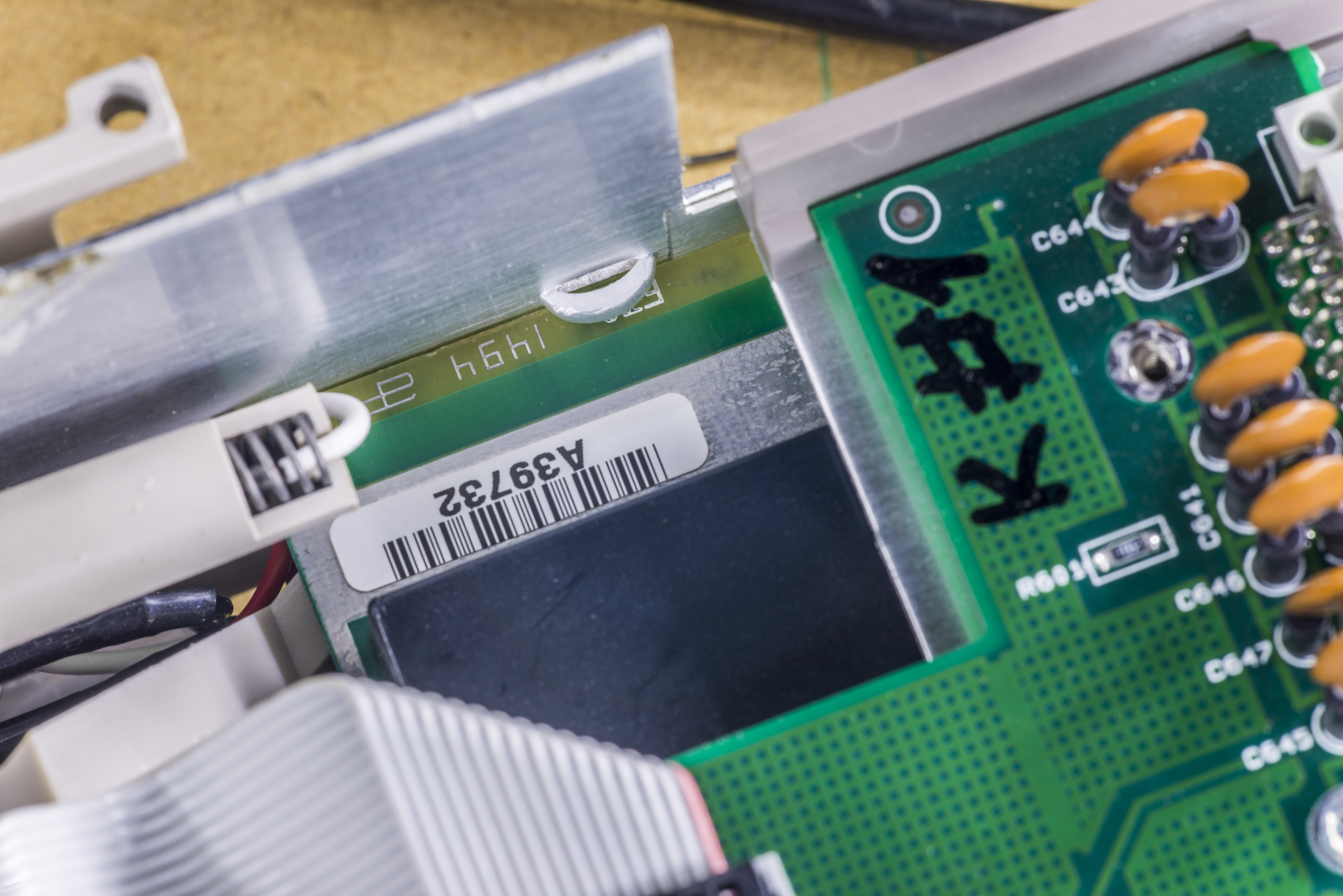
There is easy way to read and backup calibration ROM as well, using external programmer, such as TL866. Procedure and connections shown on photograph below.
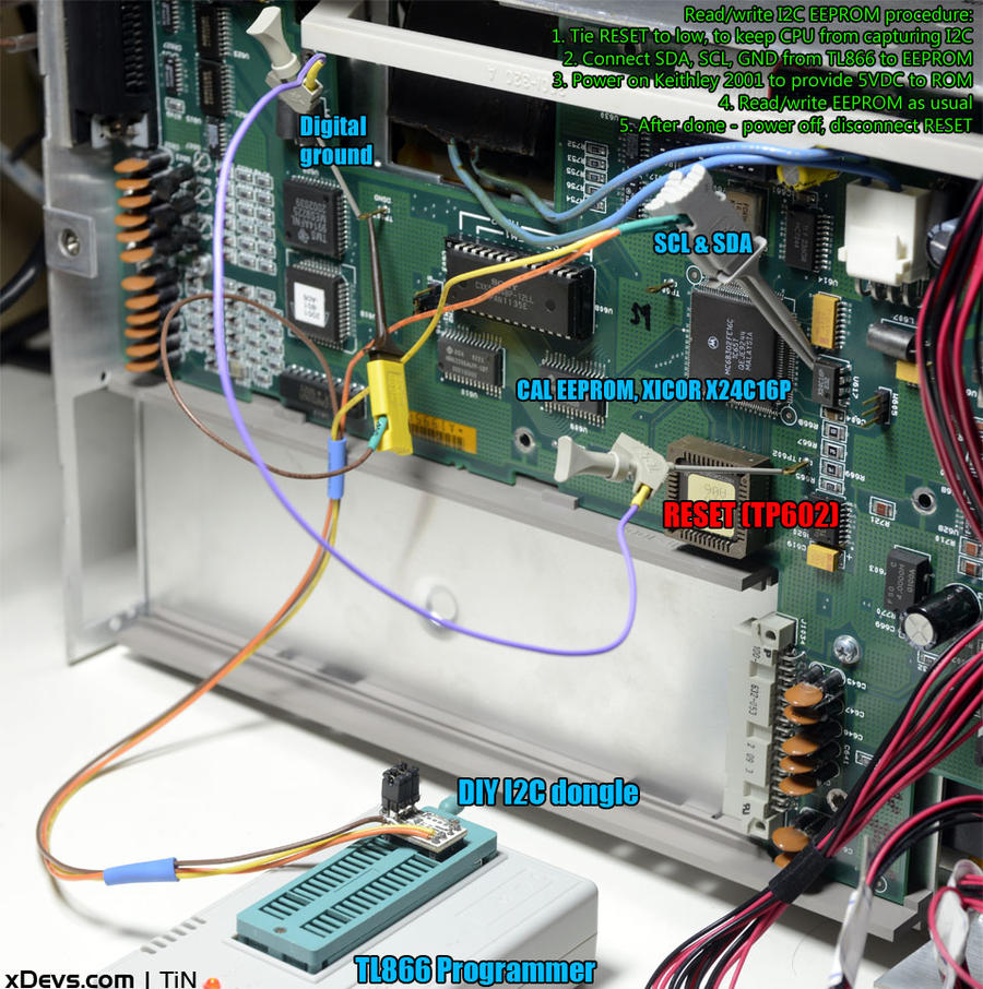
It’s wise to backup calibration ROM before attempting own recalibration or sending unit to service, just in case. Some of my calibration ROM dumps:
| Calibration ROM | Dump |
|---|---|
| DigPCB: A07967, Year 2014, Unit 0544257, Tektronix TW cal | Binary |
| DigPCB: A19956, Year 1993, Unit 0549310 | Binary |
| DigPCB: A14641, Year 1998, Unit 0546015 | Binary |
| DigPCB: A10142, Year 2000, Unit 0545483 | Binary |
| DigPCB: A39541, Year 1994, Unit 0579220 | Binary |
| DigPCB: A09513, Year 1992, Unit 0545274 | Binary |
| DigPCB: A07543, Year 1999, Unit 0544015 | Binary |
Many of these and other Keithley Instruments firmware dumps are available on xDevs.com documentation archive tree. If you have Keithley Model 2001 firmware (or any other Keithley instrument firmware), please upload here.
Calibration decode for EEPROM contents
Calibration constants from K2001 can be read using GPIB command. They are stored in plain binary format in the ROM. Table C-2 of 2001-905-01G calibration manual lists the response to the :CAL:PROT:DATA? query. The response is an ASCII string of 99 numbers separated by commas, and is not affected by the FORMAT command. Constants listed in Table C-2 are shown in the order they are sent.
| Constant name | Unit K2001 #7 | Unit K2001 #1 | Detailed description | ROM Offset | Data format |
|---|---|---|---|---|---|
| g1 | 1.000038E+00 | 9.997173E-01 | RMS gain for 2V, 200V, and 750V AC ranges | 0×018 | double float IEEE 754 |
| of1 | 1.533712E-04 | -1.583679E-04 | RMS offset for 2V, 200V, and 750V AC ranges | 0×020 | double float IEEE 754 |
| g10 | 1.000523E+01 | 1.000293E+01 | RMS gain for 200mV and 20V AC ranges | 0×028 | double float IEEE 754 |
| of10 | 1.704422E-04 | -1.076852E-04 | RMS offset for 200mV and 20V AC ranges | 0×030 | double float IEEE 754 |
| gfwr1 | 9.999993E-01 | 9.999961E-01 | Average gain for 2V, 200V, and 750V AC ranges | 0×038 | double float IEEE 754 |
| offwr1 | 2.698059E-05 | -3.915291E-05 | Average offset for 2V, 200V, and 750V AC ranges | 0×040 | double float IEEE 754 |
| gfwr10 | 1.000433E+01 | 1.000551E+01 | Average gain for 200mV and 20V AC ranges | 0×048 | double float IEEE 754 |
| offwr10 | 1.689877E-04 | 8.726960E-05 | Average offset for 200mV and 20V AC ranges | 0×050 | double float IEEE 754 |
| a100 | 1.000210E+02 | 9.998019E+01 | 100:1 divider attenuation factor | 0×058 | double float IEEE 754 |
| a500 | 4.963352E+02 | 4.962888E+02 | 500:1 divider attenuation factor | 0×060 | double float IEEE 754 |
| ofpkpos10 | 6.097749E-03 | 1.418733E-02 | Positive peak offset for 200mV AC range | 0×068 | double float IEEE 754 |
| ofpkneg10 | 1.117921E-02 | 1.722747E-02 | Negative peak offset for 200mV AC range | 0×070 | double float IEEE 754 |
| ofpk1 | 4.573312E-03 | 4.053523E-03 | Positive and negative peak offset for 2V, 200V, and 750V AC ranges | 0×078 | double float IEEE 754 |
| ofpkpos20 | 6.097749E-03 | 7.600356E-03 | Positive peak offset for 20V AC range | 0×080 | double float IEEE 754 |
| ofpkneg20 | 1.117921E-02 | 7.093666E-03 | Negative peak offset for 20V AC range | 0×088 | double float IEEE 754 |
| div100self | 1.125000E+02 | 1.340000E+02 | Self-calibration code for frequency compensation DAC, 100:1 divider | 0×090 | double float IEEE 754 |
| div500self | 9.000000E+01 | 1.260000E+02 | Self-calibration code for frequency compensation DAC, 500:1 divider | 0×098 | double float IEEE 754 |
| noise10 | 1.864359E-04 | 2.238526E-04 | Noise factor for 200mV and 20V AC ranges | 0×0a0 | double float IEEE 754 |
| cfc1 | 1.000331E+00 | 1.000316E+00 | Crest factor correction factor for 2V, 200V, and 750V AC ranges | 0×0a8 | double float IEEE 754 |
| cfc10 | 1.000021E+00 | 1.000284E+00 | Crest factor correction factor for 200mV and 20V AC ranges | 0×0b0 | double float IEEE 754 |
| acdclow | 1.000346E+00 | 1.000340E+00 | AC-coupled correction factor for 200mV and 2V AC ranges | 0×0b8 | double float IEEE 754 |
| acdchigh | 1.000199E+00 | 1.000192E+00 | AC-coupled correction factor for 20V, 200V, and 750V AC ranges | 0×0c0 | double float IEEE 754 |
| inputtc | 1.081469E-01 | 1.044814E-01 | Input time constant | 0×0c8 | double float IEEE 754 |
| acdccur | 1.000348E+00 | 1.000487E+00 | AC-coupled correction factor for AC current | 0×0d0 | double float IEEE 754 |
| compval1 | 1.215000E+02 | 1.190000E+02 | RMS comparator DAC code | 0×0d8 | double float IEEE 754 |
| div100 | 1.135000E+02 | 1.340000E+02 | Frequency-compensation DAC code for 20V AC range | 0×0e0 | double float IEEE 754 |
| div200 | 1.130000E+02 | 1.330000E+02 | Frequency-compensation DAC code for 200V AC range | 0×0e8 | double float IEEE 754 |
| div500 | 9.300000E+01 | 1.220000E+02 | Frequency-compensation DAC code for 750V AC range | 0×0f0 | double float IEEE 754 |
| div100off | 1.000000E+00 | 0.000000E+00 | Frequency-compensation DAC offset for 20V AC range | 0×0f8 | double float IEEE 754 |
| div200off | 5.000000E-01 | -1.000000E+00 | Frequency compensation DAC offset for 200V AC range | 0×100 | double float IEEE 754 |
| div500off | 3.000000E+00 | -4.000000E+00 | Frequency compensation DAC offset for 750V AC range | 0×108 | double float IEEE 754 |
| Check sum | 0xA5 0xB4 | 16-bit summator of cal values 0×18 – 0×108 | 0×110 | 2 bytes, 16 bits | |
| dcv[200mV]gain | 1.395384E+00 | 1.385034E+00 | 200mV DC gain | 0×112 | double float IEEE 754 |
| dcv[200mV]offset | -1.541521E-05 | -5.612224E-05 | 200mV DC offset | 0×11a | double float IEEE 754 |
| dcv[2V]gain | 1.743986E+00 | 1.730974E+00 | 2V DC gain | 0×122 | double float IEEE 754 |
| dcv[2V]offset | -1.732121E-06 | -5.877960E-06 | 2V DC offset | 0×12a | double float IEEE 754 |
| dcv[20V]gain | -6.976404E-01 | -6.924144E-01 | 20V DC gain | 0×132 | double float IEEE 754 |
| dcv[20V]offset | -1.150898E-05 | -3.787601E-05 | 20V DC offset | 0×13a | double float IEEE 754 |
| dcv[200V]gain | 1.743655E+00 | 1.730672E+00 | 200V DC gain | 0×142 | double float IEEE 754 |
| dcv[200V]offset | -1.008386E-06 | 2.410488E-06 | 200V DC offset | 0×14a | double float IEEE 754 |
| dcv[1000V]gain | 6.975011E-01 | 6.922715E-01 | 100V DC gain | 0×152 | double float IEEE 754 |
| dcv[1000V]offset | 5.484389E-04 | -1.772726E-03 | 1000V DC offset | 0×15a | double float IEEE 754 |
| dca[200uA]gain | 1.396956E+00 | 1.386757E+00 | 200ΩA DC gain | 0×162 | double float IEEE 754 |
| dca[200uA]offset | -1.814614E-05 | 1.600430E-04 | 200ΩA DC offet | 0×16a | double float IEEE 754 |
| dca[2mA]gain | 1.397030E+00 | 1.386588E+00 | 2mA DC gain | 0×172 | double float IEEE 754 |
| dca[2mA]offset | -2.236752E-05 | 1.604392E-04 | 2mA DC offset | 0×17a | double float IEEE 754 |
| dca[20mA]gain | 1.394508E+00 | 1.384073E+00 | 20mA DC gain | 0×182 | double float IEEE 754 |
| dca[20mA]offset | -2.232714E-05 | 1.601482E-04 | 20mA DC offset | 0×18a | double float IEEE 754 |
| dca[200mA]gain | 1.379412E+00 | 1.370280E+00 | 200mA DC gain | 0×192 | double float IEEE 754 |
| dca[200mA]offset | -2.208545E-05 | 1.585523E-04 | 200mA DC offset | 0×19a | double float IEEE 754 |
| dca[2A]gain | 1.394483E+00 | 1.384269E+00 | 2A DC gain | 0×1a2 | double float IEEE 754 |
| dca[2A]offset | -2.232674E-05 | 1.601709E-04 | 2A DC offset | 0×1aa | double float IEEE 754 |
| ohm220gain | 1.500375E+00 | 1.516462E+00 | 2-wire 20Ω gain | 0×1b2 | double float IEEE 754 |
| ohm220offset | -9.411514E-03 | -1.058161E-02 | 2-wire 20Ω offset | 0×1ba | double float IEEE 754 |
| ohm2200gain | 1.430062E+00 | 1.430543E+00 | 2-wire 200Ω gain | 0×1c2 | double float IEEE 754 |
| ohm2200offset | -9.552922E-04 | -1.109982E-03 | 2-wire 200Ω offset | 0×1ca | double float IEEE 754 |
| ohm2[2k]gain | 1.787328E+00 | 1.787851E+00 | 2-wire 2kΩ gain | 0×1d2 | double float IEEE 754 |
| ohm2[2k]offset | -9.572465E-05 | -1.112534E-04 | 2-wire 2kΩ offset | 0×1da | double float IEEE 754 |
| ohm2[20k]gain | 1.965853E+00 | 1.966221E+00 | 2-wire 20kΩ gain | 0×1e2 | double float IEEE 754 |
| ohm2[20k]offset | -1.134743E-05 | -1.719503E-05 | 2-wire 20kΩ offset | 0×1ea | double float IEEE 754 |
| ohm2[200k]gain | 2.479002E+00 | 2.475204E+00 | 2-wire 200kΩ gain | 0×1f2 | double float IEEE 754 |
| ohm2[200k]offset | -3.401631E-06 | -9.457002E-06 | 2-wire 200kΩ offset | 0×1fa | double float IEEE 754 |
| ohm2[2M]gain | 2.273309E+00 | 2.272104E+00 | 2-wire 2MΩ gain | 0×202 | double float IEEE 754 |
| ohm2[2M]offset | -2.351793E-06 | -7.820685E-06 | 2-wire 2MΩ offset | 0×20a | double float IEEE 754 |
| ohm2[20M]gain | 2.503775E+00 | 2.493262E+00 | 2-wire 20MΩ gain | 0×212 | double float IEEE 754 |
| ohm2[20M]offset | -2.496137E-06 | -8.477018E-06 | 2-wire 20MΩ offset | 0×21a | double float IEEE 754 |
| ohm2[200M]gain | 3.925414E+00 | 3.909291E+00 | 2-wire 200MΩ gain | 0×222 | double float IEEE 754 |
| ohm2[200M]offset | 1.234136E-02 | -4.004449E-02 | 2-wire 200MΩ offset | 0×22a | double float IEEE 754 |
| ohm2[1G]gain | 1.570253E+00 | 1.563722E+00 | 2-wire 1GΩ gain | 0×232 | double float IEEE 754 |
| ohm2[1G]offset | 1.234442E-03 | -4.003584E-03 | 2-wire 1GΩ offset | 0×23a | double float IEEE 754 |
| ohm420gain | 1.500375E+00 | 1.516462E+00 | 4-wire 20Ω gain | 0×242 | double float IEEE 754 |
| ohm420offset | 3.446987E-05 | 4.566308E-05 | 4-wire 20Ω offset | 0×24a | double float IEEE 754 |
| ohm4200gain | 1.430062E+00 | 1.430543E+00 | 4-wire 200Ω gain | 0×252 | double float IEEE 754 |
| ohm4200offset | 3.285450E-05 | 4.307594E-05 | 4-wire 200Ω offset | 0×25a | double float IEEE 754 |
| ohm4[2k]gain | 1.787328E+00 | 1.787851E+00 | 4-wire 2kΩ gain | 0×262 | double float IEEE 754 |
| ohm4[2k]offset | 3.026024E-06 | 4.242987E-06 | 4-wire 2kΩ offset | 0×26a | double float IEEE 754 |
| ohm4[20k]gain | 1.965853E+00 | 1.966221E+00 | 4-wire 20kΩ gain | 0×272 | double float IEEE 754 |
| ohm4[20k]offset | 3.328274E-06 | 4.666301E-06 | 4-wire 20kΩ offset | 0×27a | double float IEEE 754 |
| ohm4[200k]gain | 2.479002E+00 | 2.475204E+00 | 4-wire 200kΩ gain | 0×282 | double float IEEE 754 |
| ohm4[200k]offset | 4.197058E-06 | 5.874237E-06 | 4-wire 200kΩ offset | 0×28a | double float IEEE 754 |
| n7vref | 6.976333E-01 | 6.923925E-01 | 7V reference value | 0×2d2 | double float IEEE 754 |
| rollover | 9.999967E-01 | 9.999954E-01 | ±2V rollover | 0×2da | double float IEEE 754 |
| mux4d711 | 15813 | 15897 | Multiplexer 4-1/2 digit counts (AC peak) | 0×2e2 | uint32_t |
| mux4d711p5 | 8951 | 9068 | Multiplexer 4-1/2 digit counts (AC peak) | 0×2e6 | uint32_t |
| mux4d215 | 12388 | 12479 | Multiplexer 4-1/2 digit counts (AC peak) | 0×2ea | uint32_t |
| mux4d011 | 29542 | 29562 | Multiplexer 4-1/2 digit counts (AC peak) | 0×2ee | uint32_t |
| mux4d015 | 29542 | 29562 | Multiplexer 4-1/2 digit counts (AC peak) | 0×2f2 | uint32_t |
| mux4d0150 | 29540 | 29561 | Multiplexer 4-1/2 digit counts (AC peak) | 0×2f6 | uint32_t |
| mux4d011p5 | 29542 | 29561 | Multiplexer 4-1/2 digit counts (AC peak) | 0×2fa | uint32_t |
| mux4dF150 | 1282 | 1296 | Multiplexer 4-1/2 digit counts (AC peak) | 0×2fe | uint32_t |
| mux4dF15 | 6456 | 6461 | Multiplexer 4-1/2 digit counts (AC peak) | 0×302 | float IEEE 754 |
| i20 | 9.300236E-03 | 9.133327E-03 | 20Ω range current source value | 0×306 | float IEEE 754 |
| i200 | 9.757503E-04 | 9.681874E-04 | 200Ω range current source value | 0×30a | float IEEE 754 |
| i2k | 9.757503E-04 | 9.681874E-04 | 2kΩ range current source value | 0×30e | float IEEE 754 |
| i20k | 8.871397E-05 | 8.803561E-05 | 20kΩ range current source value | 0×312 | float IEEE 754 |
| i200k | 7.035033E-06 | 6.993260E-06 | 200kΩ range current source value | 0×316 | float IEEE 754 |
| i2m | 7.671572E-07 | 7.618376E-07 | 2MΩ range current source value | 0×31a | float IEEE 754 |
| i20m | 6.965424E-08 | 6.942609E-08 | 20MΩ range current source value | 0×31e | float IEEE 754 |
| i200m | 4.442807E-09 | 4.427848E-09 | 200MΩ range current source value | 0×322 | float IEEE 754 |
| i1g | 4.442807E-09 | 4.427848E-09 | 1GΩ range current source value | 0×326 | float IEEE 754 |
Also extra checksum visible at 0×32A offset – 2 bytes – 0×05 0×97. Calibration date stored in ASCII , following MM/DD/YY formatting on offset 0×32C – 8 bytes. 0×334 offset has 0×00 byte. Next calibration date – ASCII MM/DD/YY on offset 0×335 – 8 bytes
All binary data stored in Big endian
Here’s example C# code to perform checksum calculation:
public static UInt16 KeithleyChecksum(byte[] buffer, int ofs, int next)
            // calculate 16-bit checksum for Keithley 2001/2700/2750 multimeter Cal EEPROM
            // - ofs ... start offset, next ... offset of byte after last byte -> size = next - ofs
        {
            if ((buffer == null) || (ofs < 0) || (next > buffer.Length))
                throw new Exception(String.Format("Invalid buffer {0}, offset {1} or size {2}.",
                    buffer != null ? buffer.Length : 0, ofs, next));
            int chk = 0;
            for (int idx = ofs; idx < next; ++idx)
                chk += buffer[idx]; // just 16-bit sum of 8-bit values
            return (UInt16) (0xffff - chk);
        }
This function provide checksum calculation. Credits to Ingo from EEVBlog forums for testing.
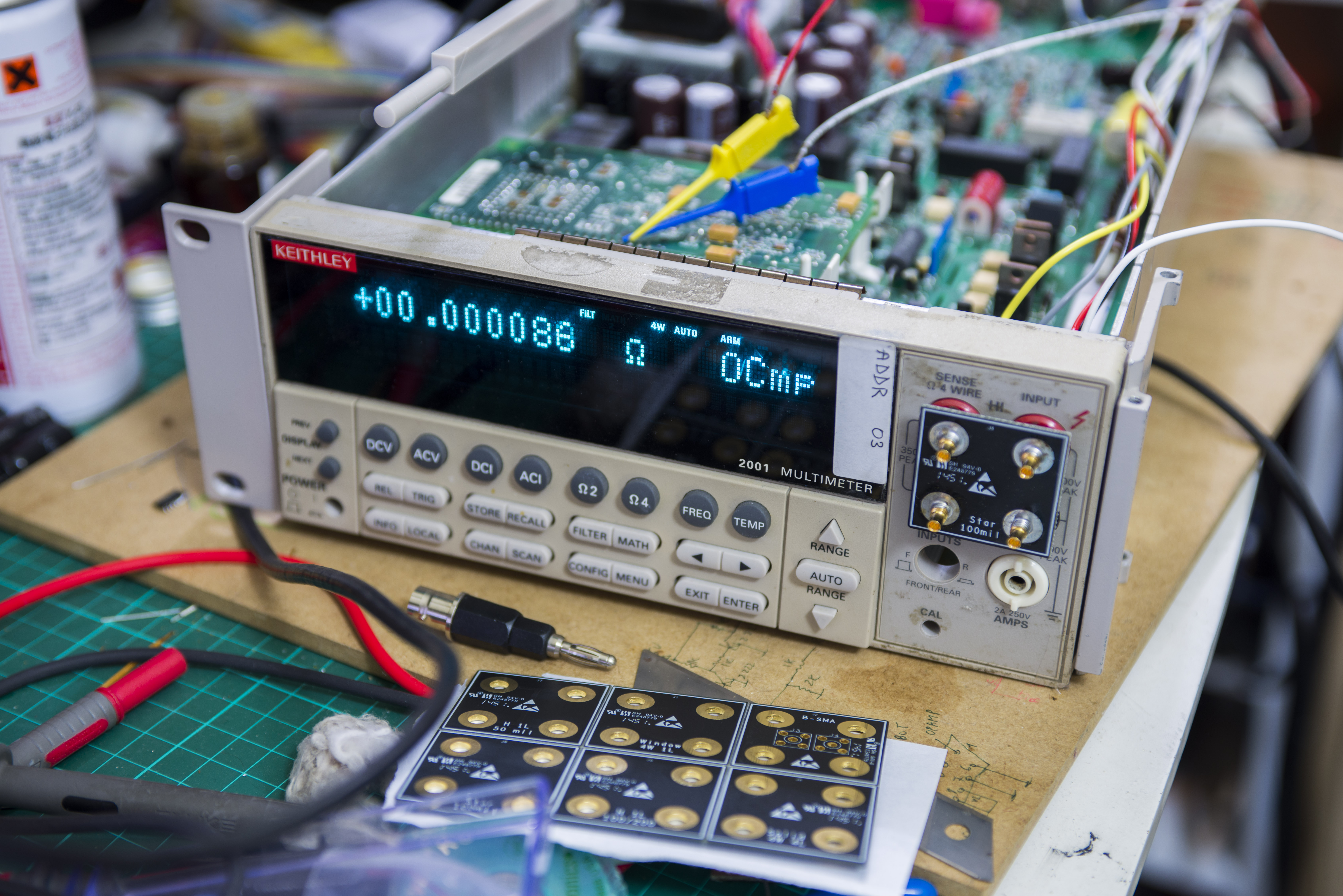
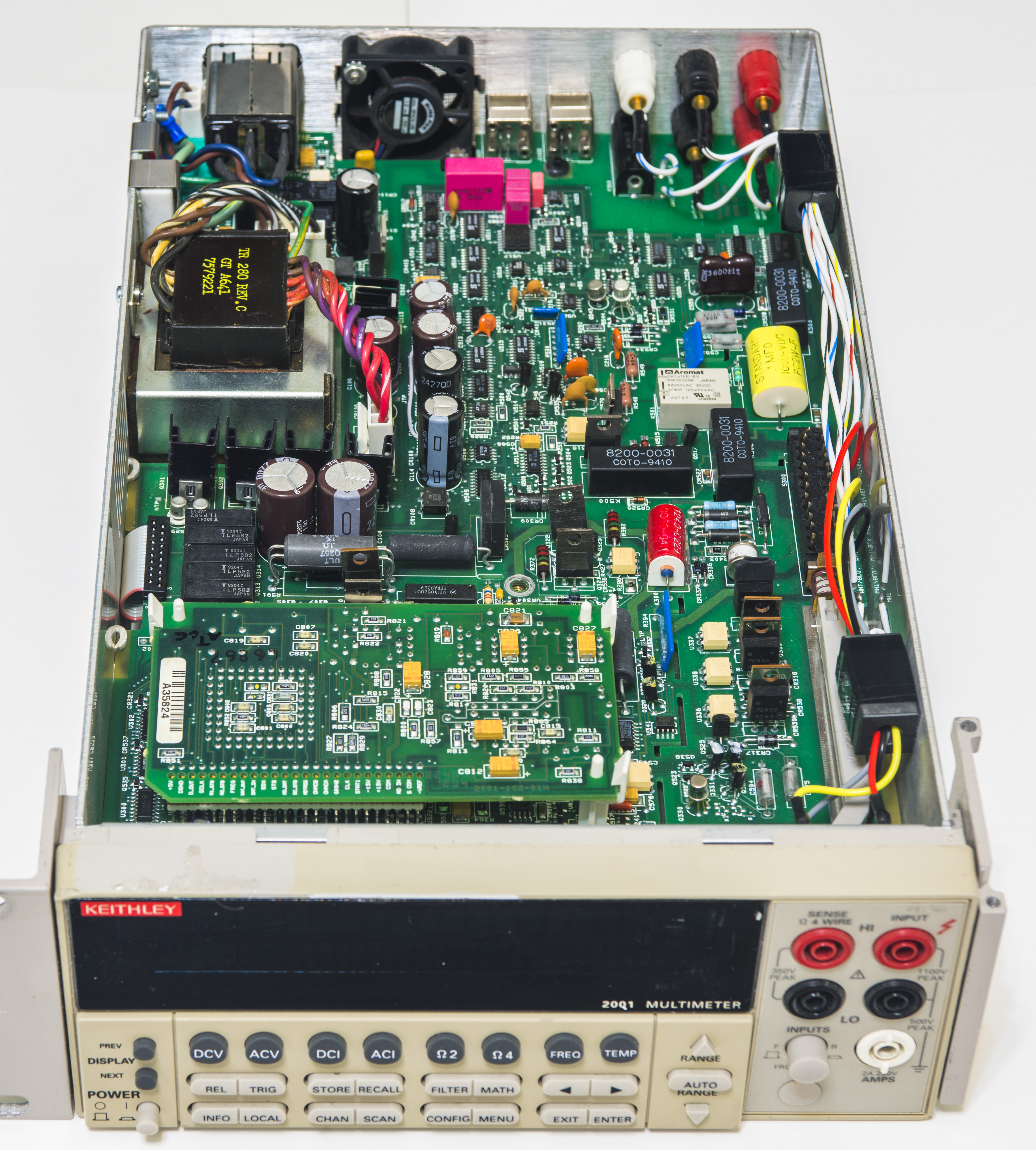
Exterior
Display and user interface
2001’s control and menu system is quick and easy to navigate through, thanks to great dot-matrix VFD screen with great contrast and brightness. Screen have two main lines for readout and auxiliary information, like current settings, statistics, and service markers on top which shows current operation mode and status. Same VFD, is used in higher end 8½-digit brother, Model 2002, switch units 7001 and 7002, and many of 24xx series and 26xx SMU instruments, as well as some other specialized Keithley meters.
Display with part-number DD-51 is custom, specially made by Newheaven Display or Noritake Itron for Keithley Instruments. It is passive glass with multiplexed segments, so all driver circuitry and display/keypad microcontroller is located on front panel. Communications with main processor is done via TTL-level UART interface. Dual line dot-matrix VFD displays in 2001 are same as many other Keithley instruments in this form-factor. Some additional notes and details about replacing aged or damaged display of this type are available in this xDevs.com article
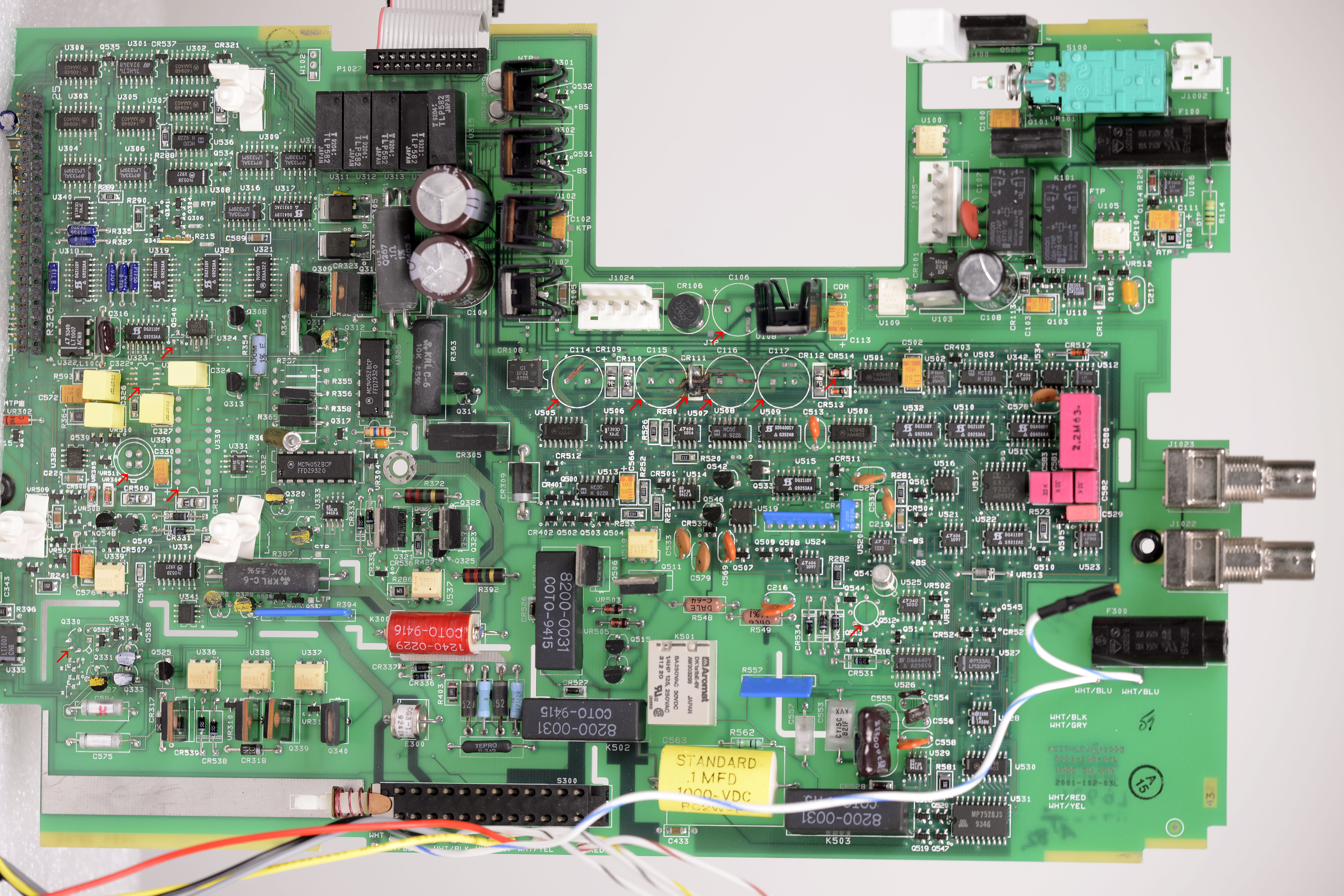
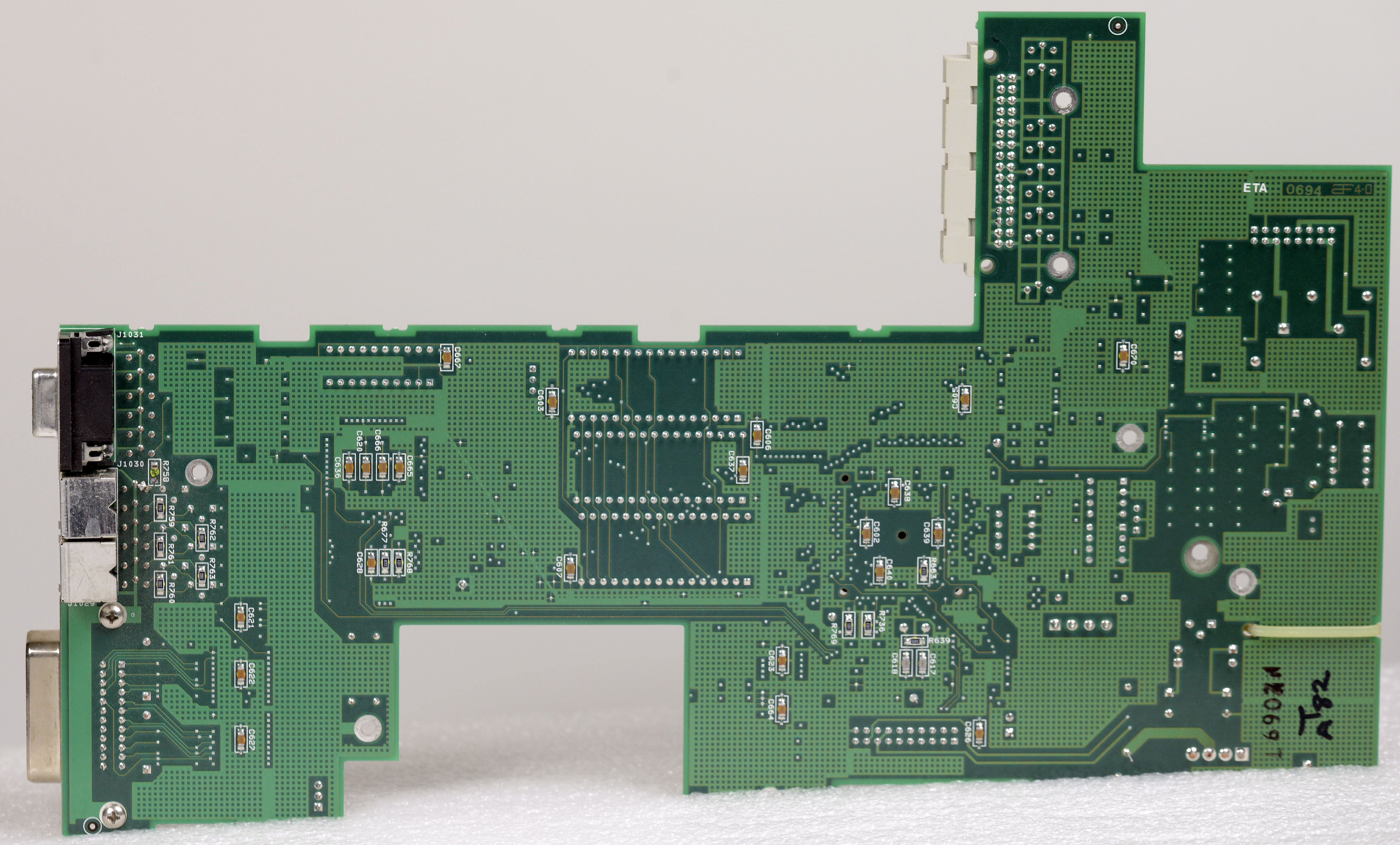
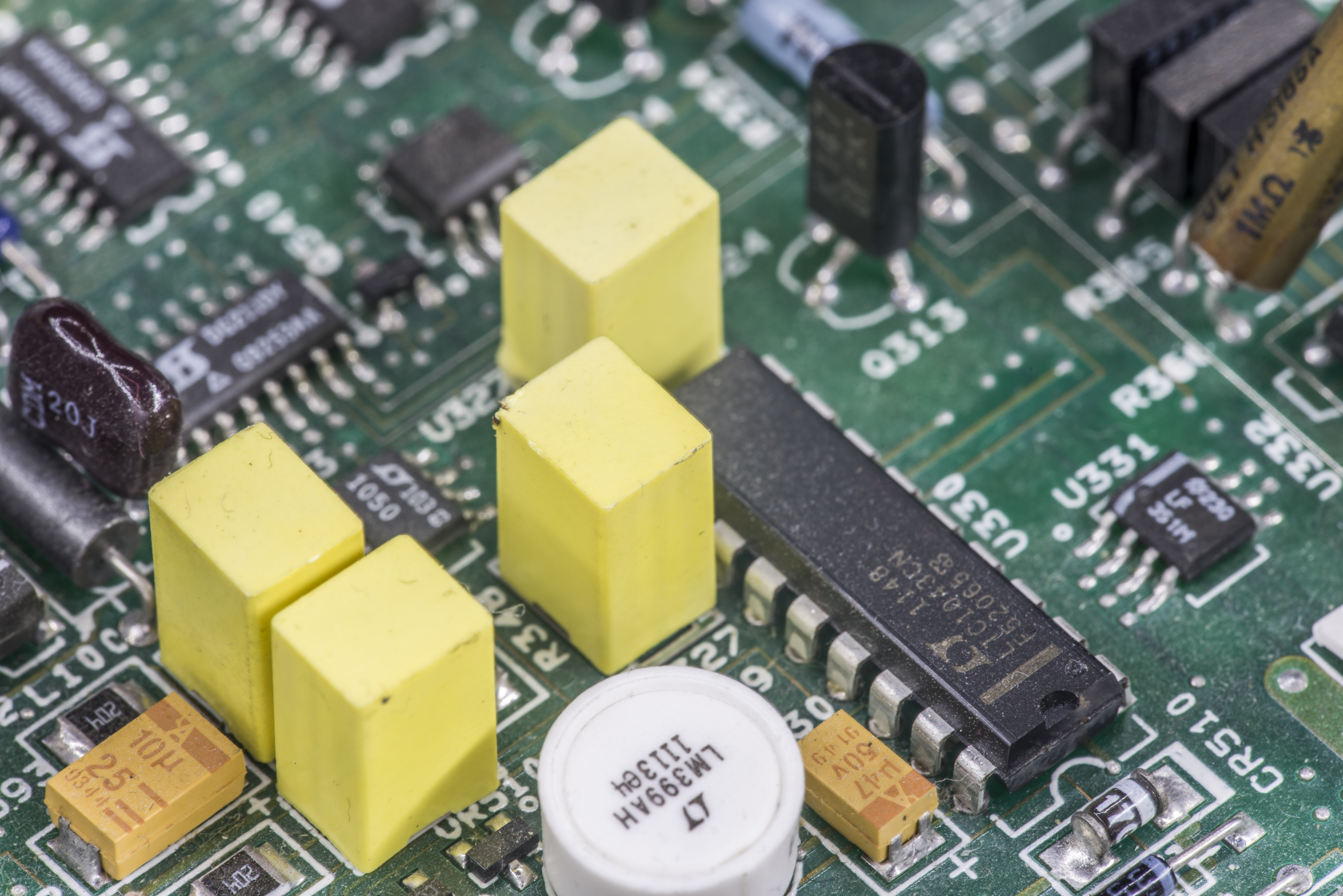
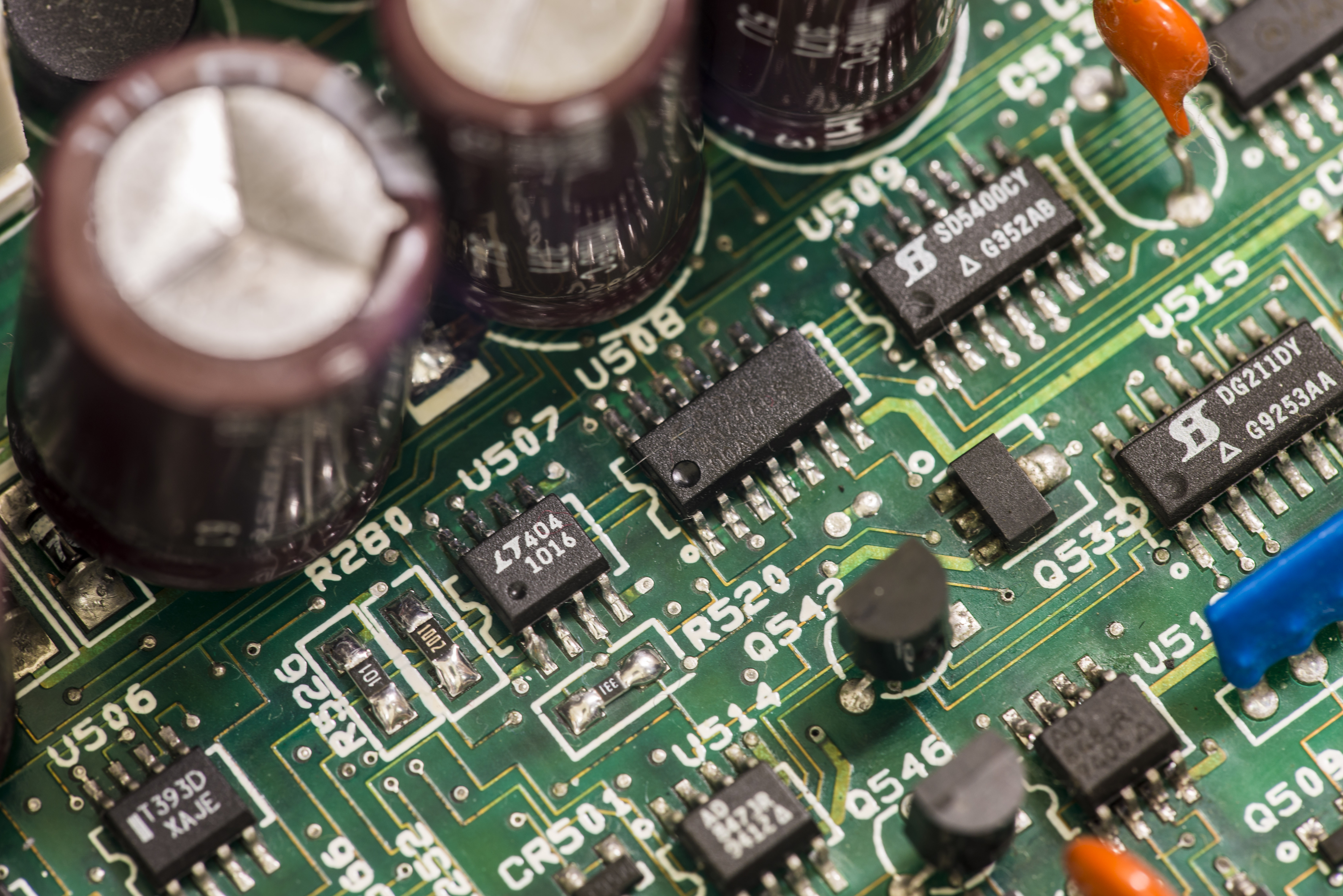
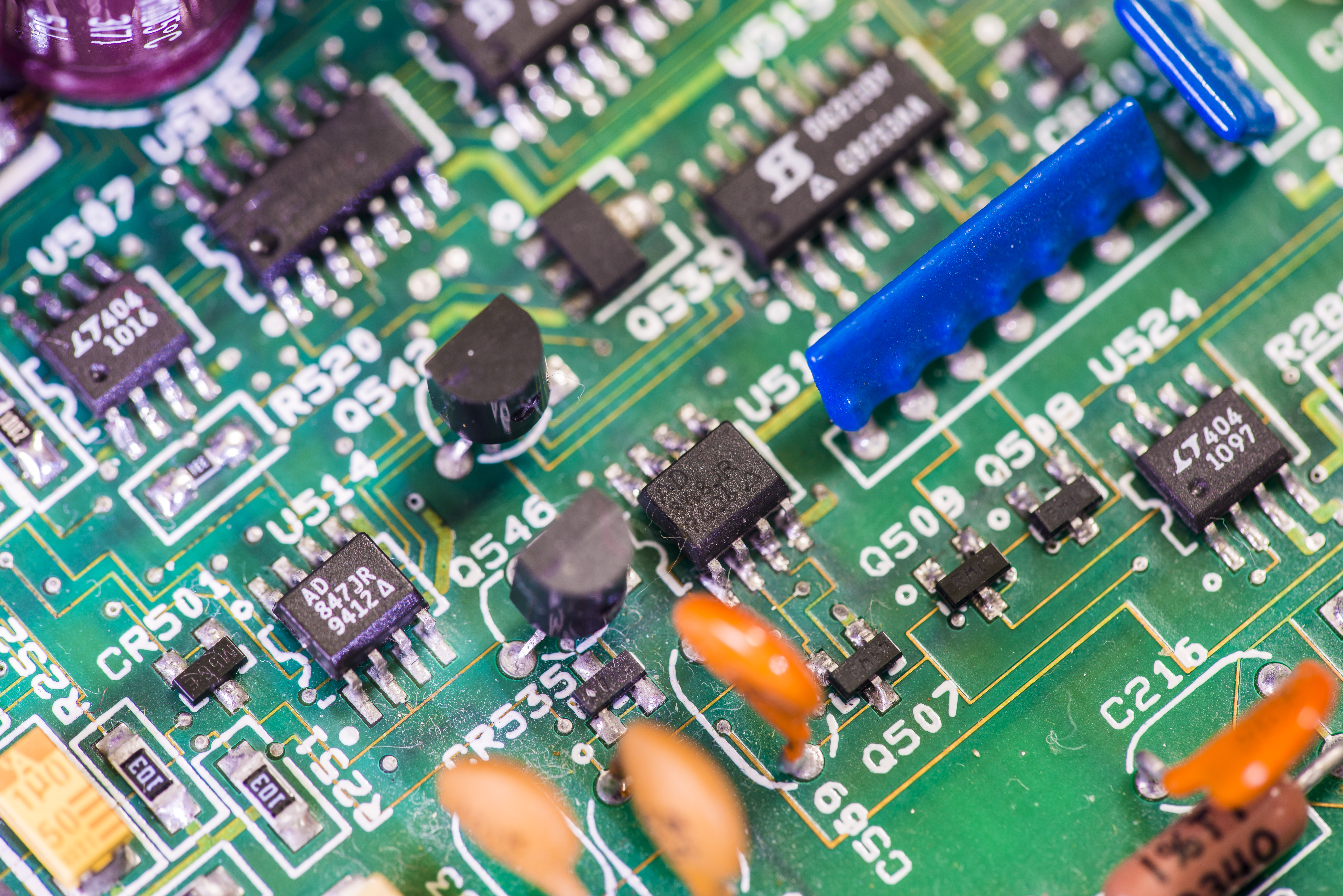
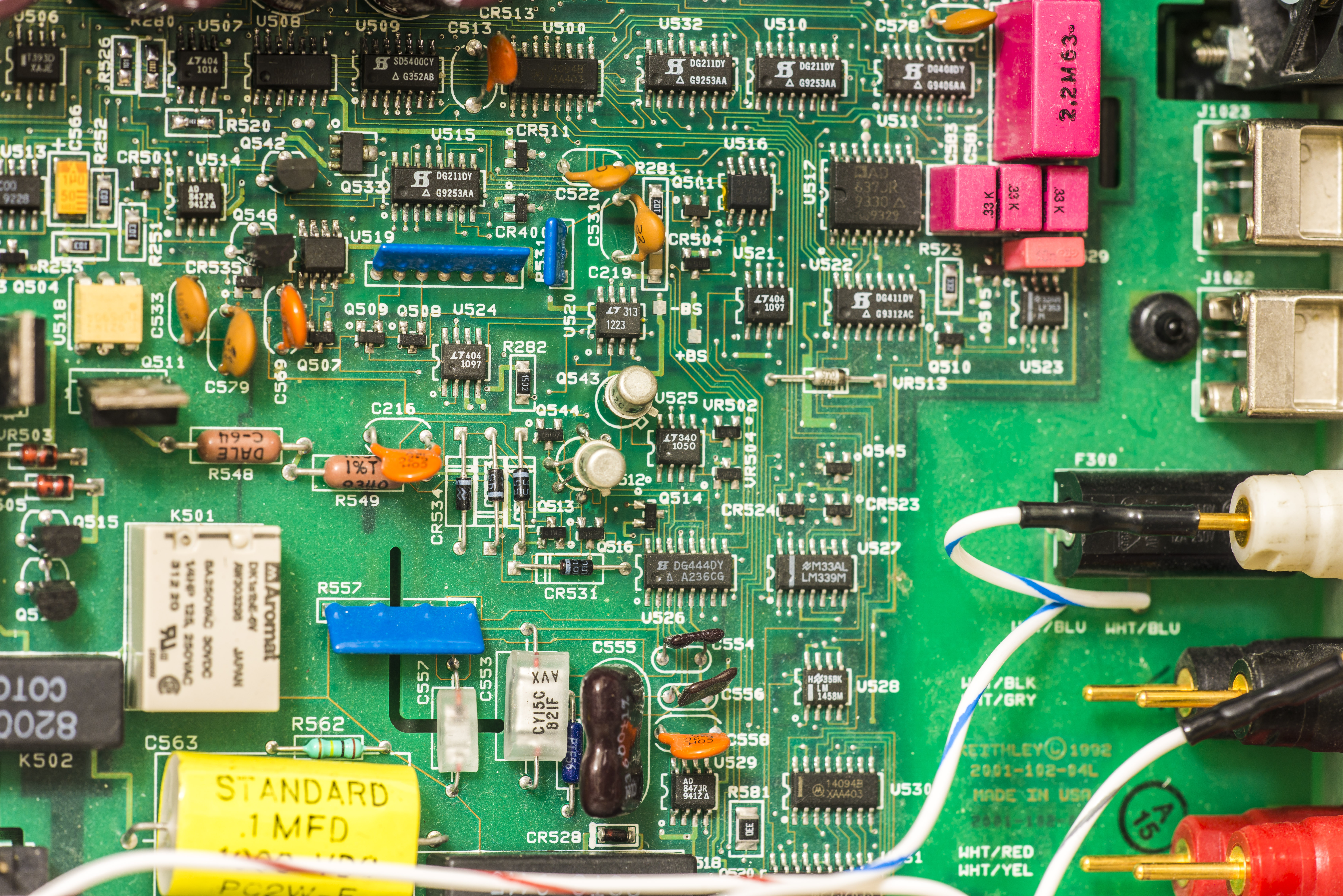
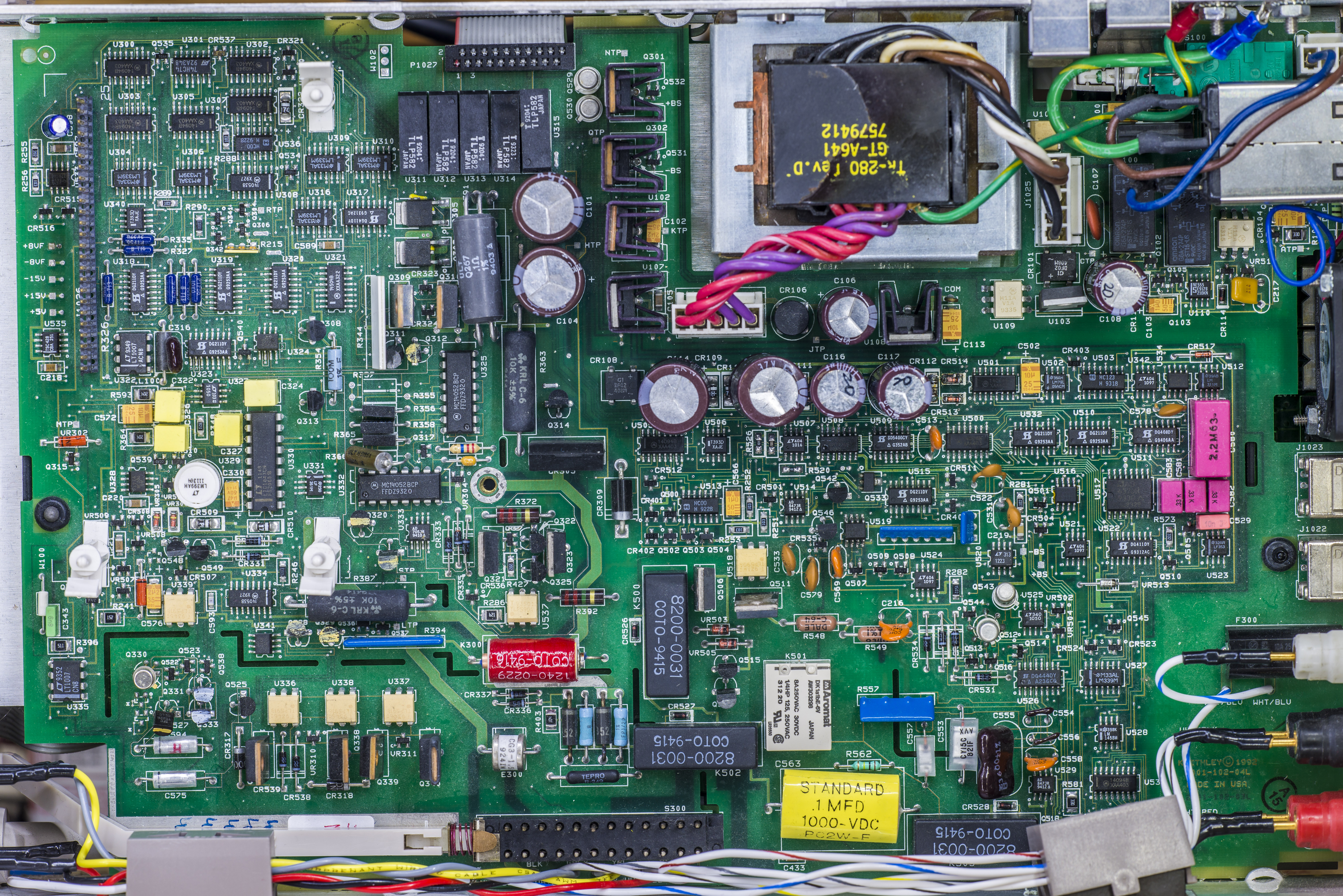
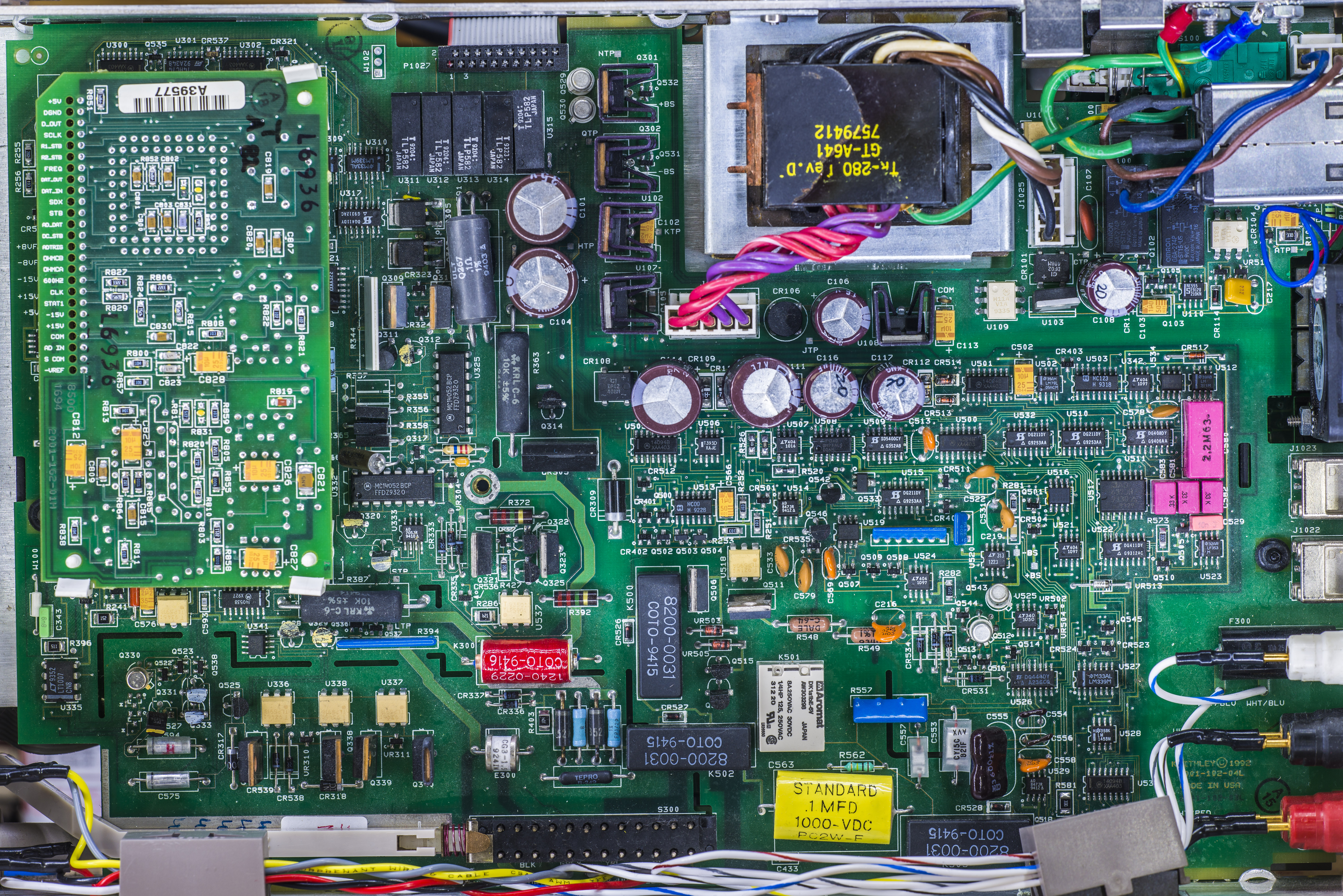
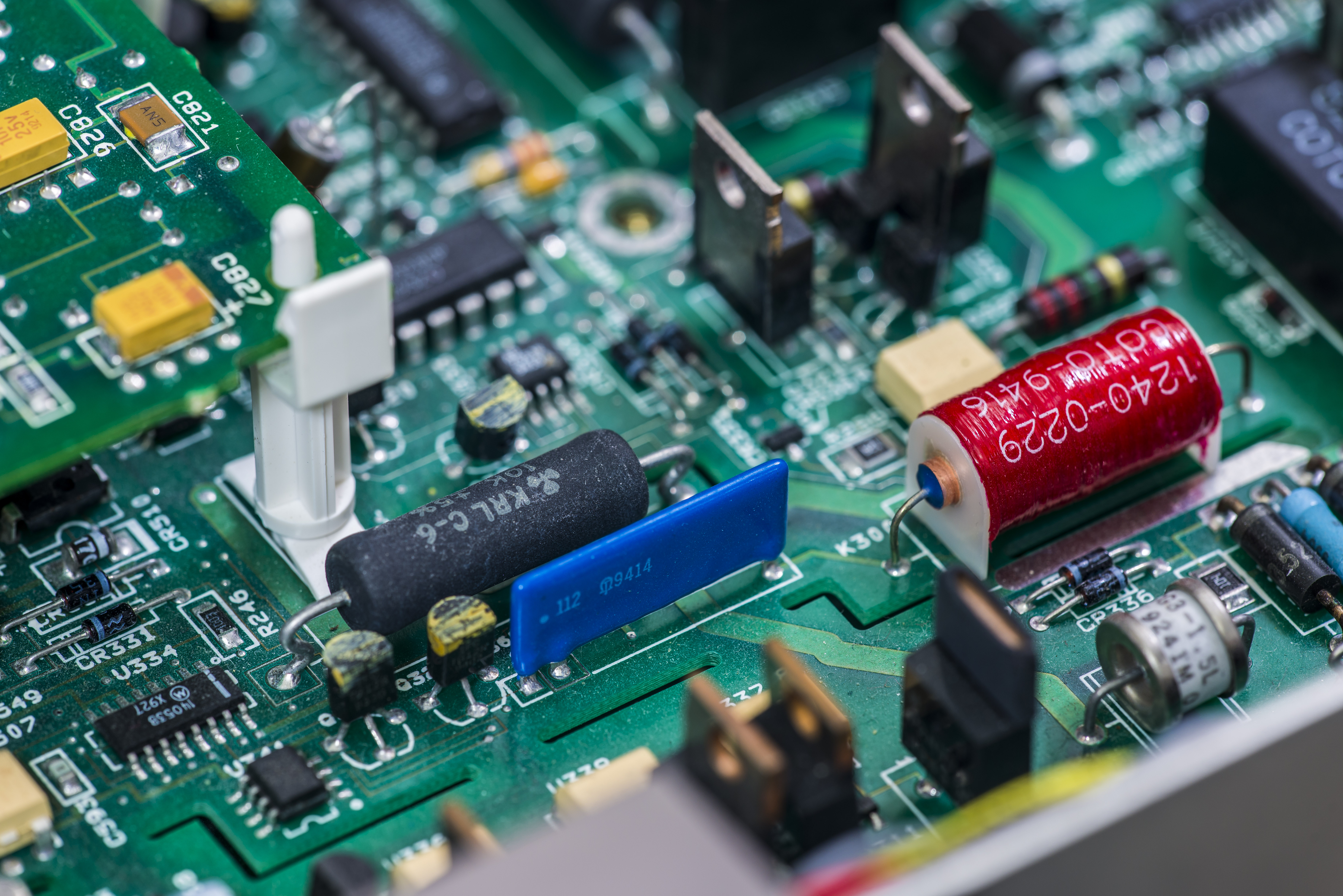
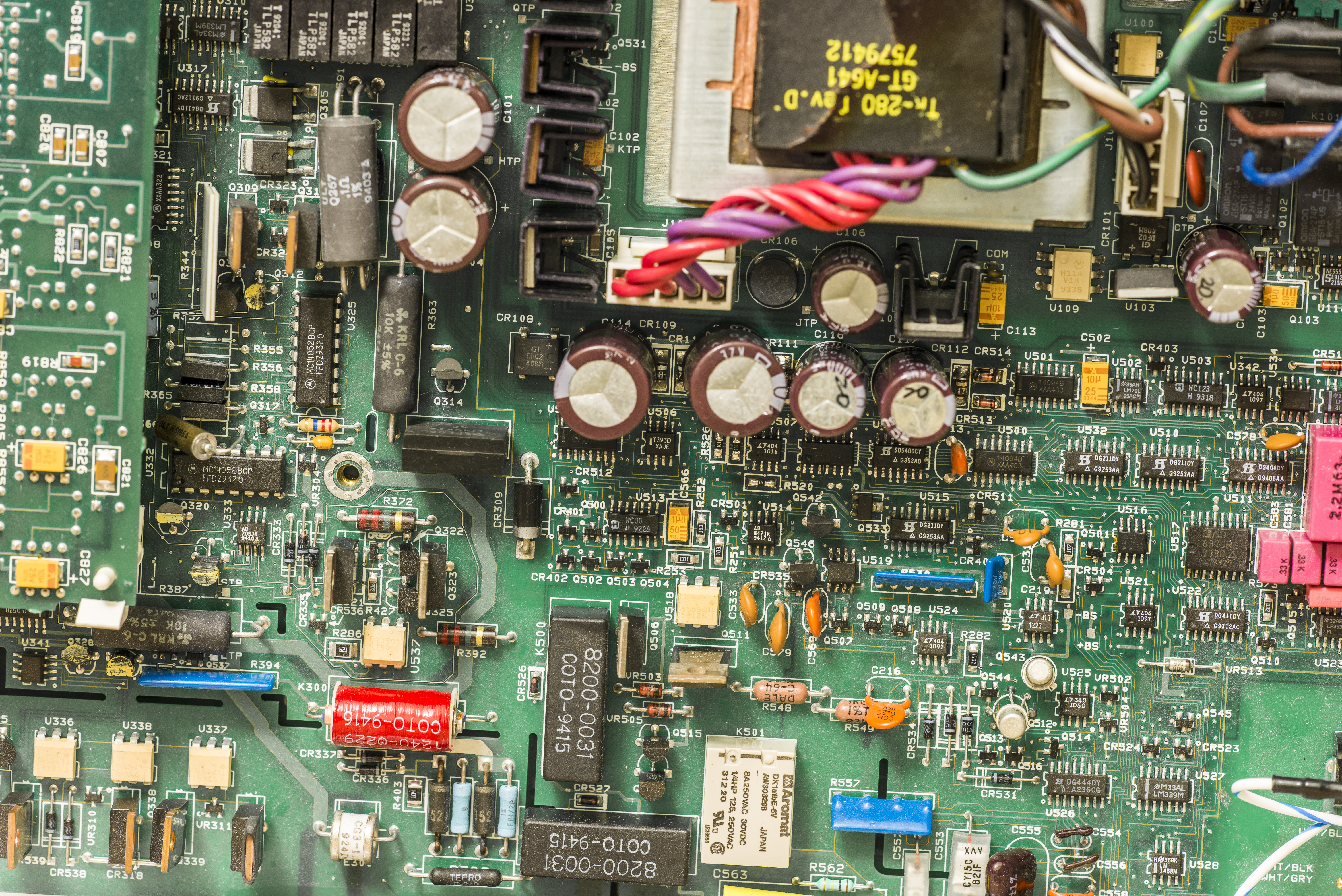
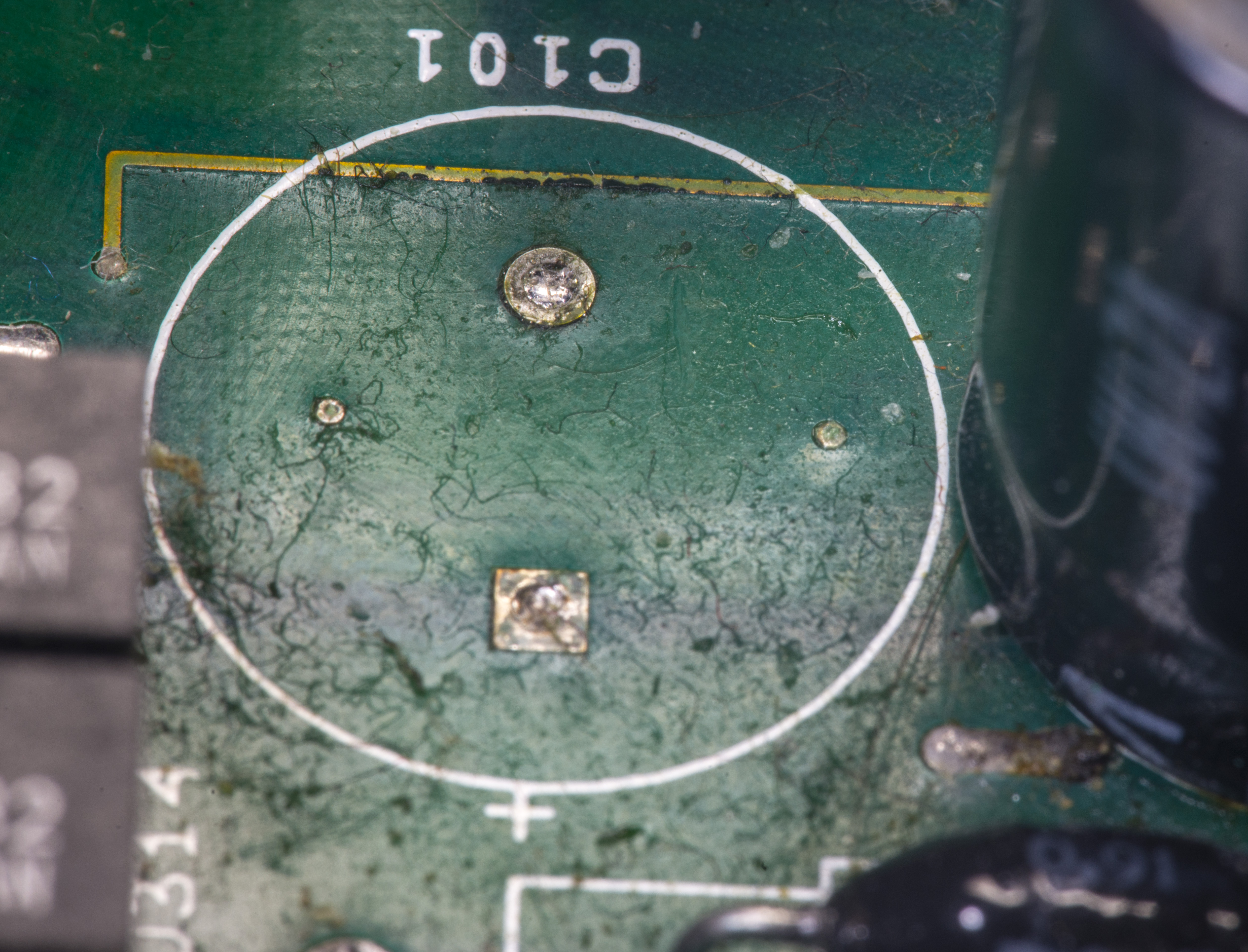
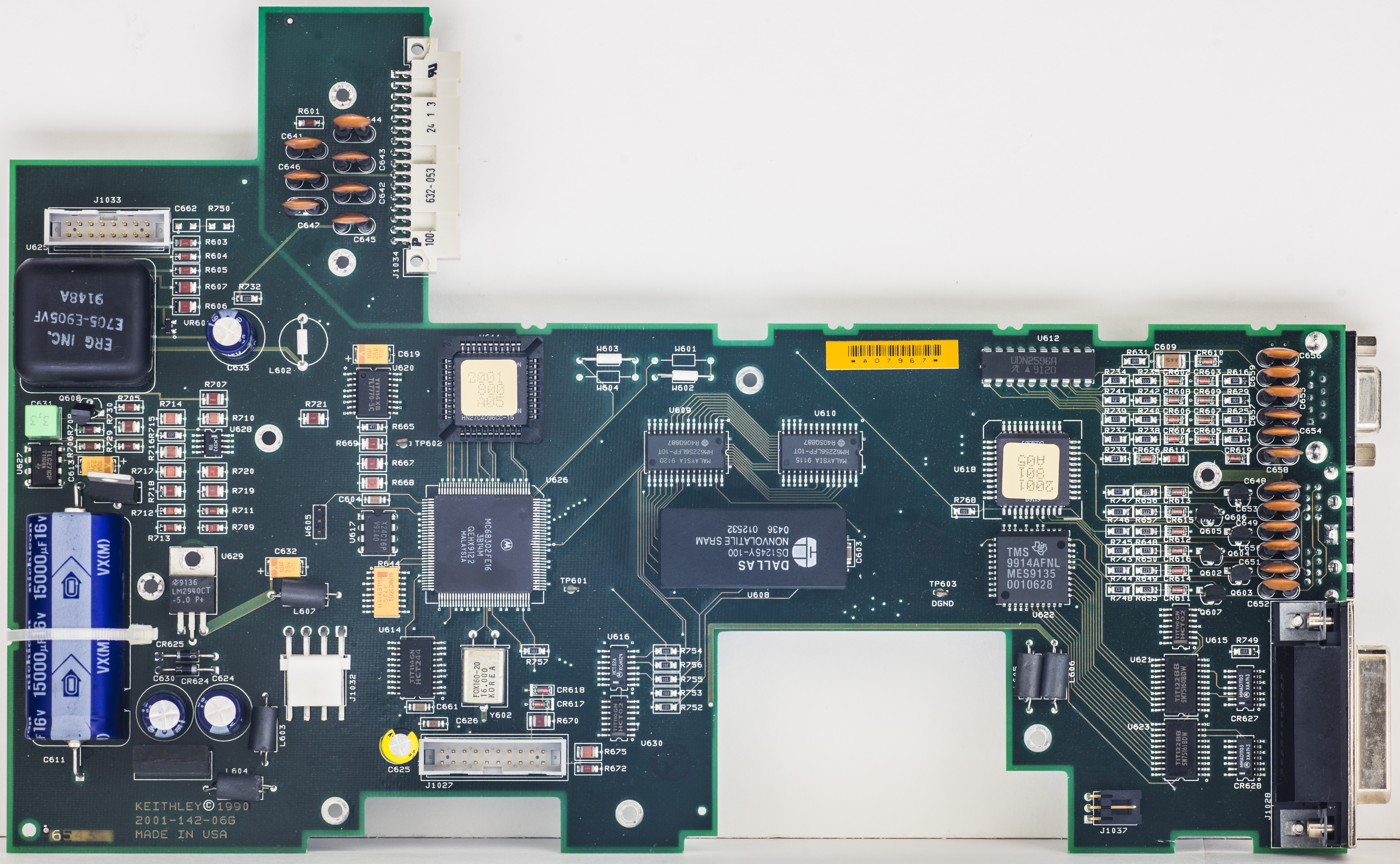
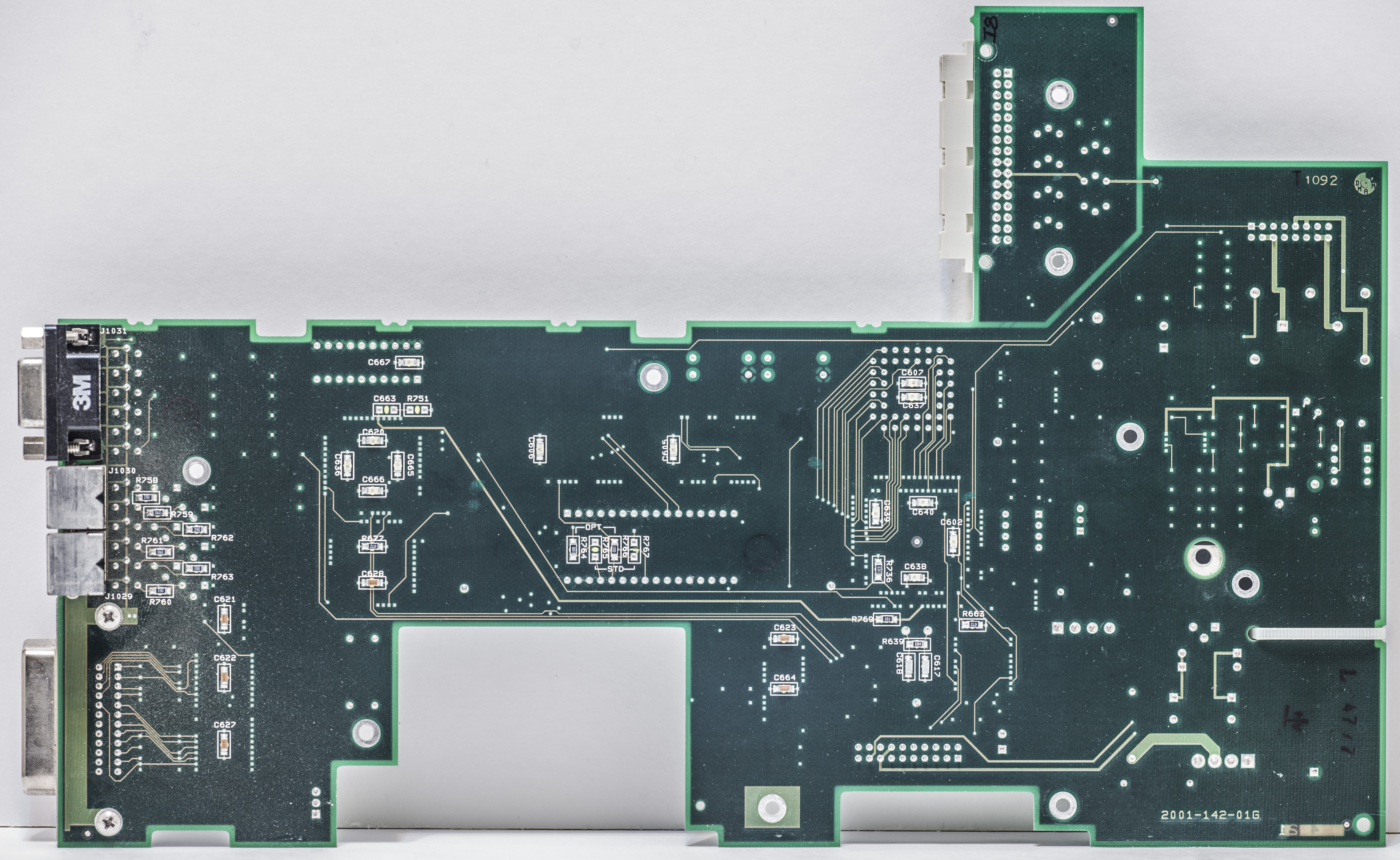
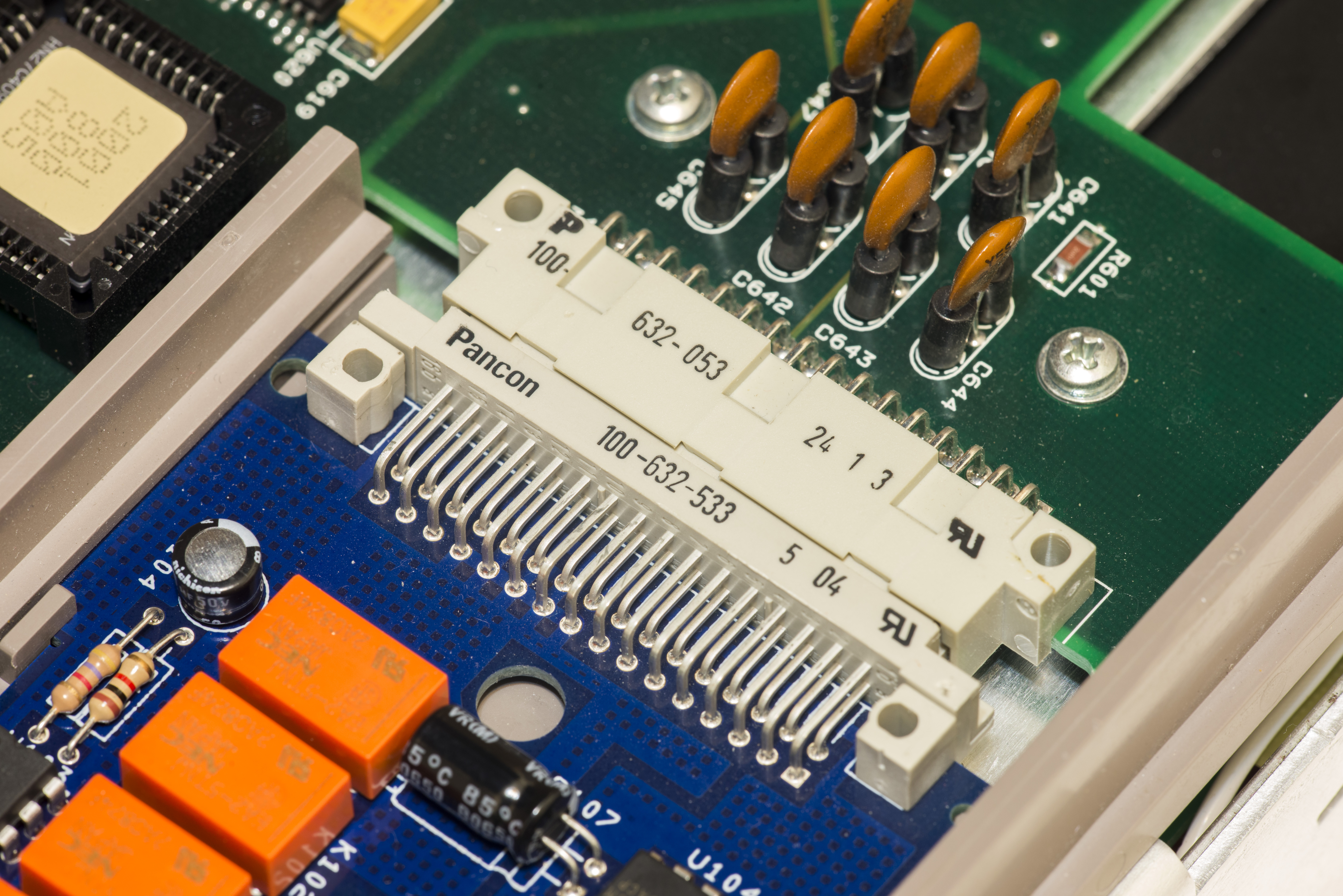
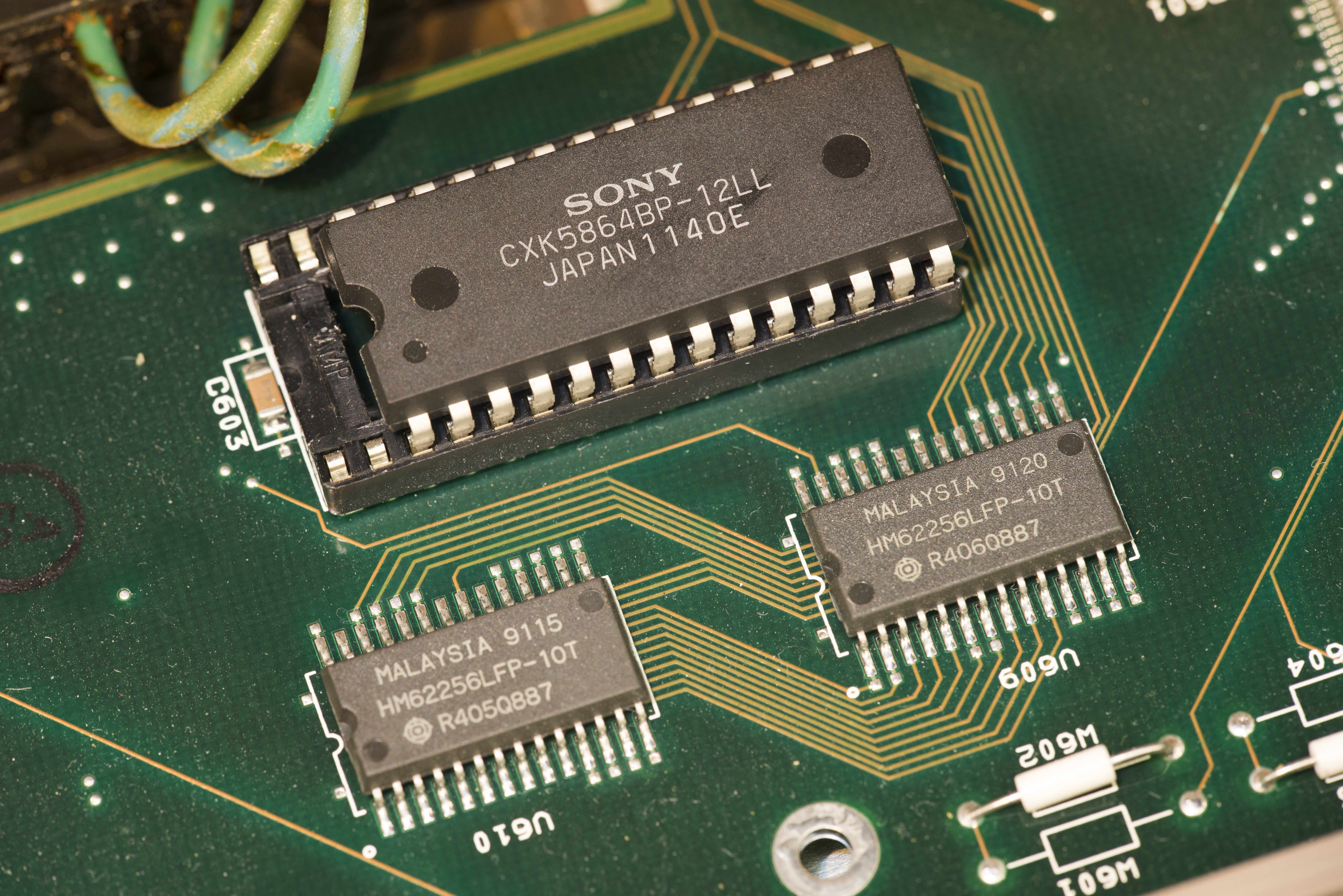
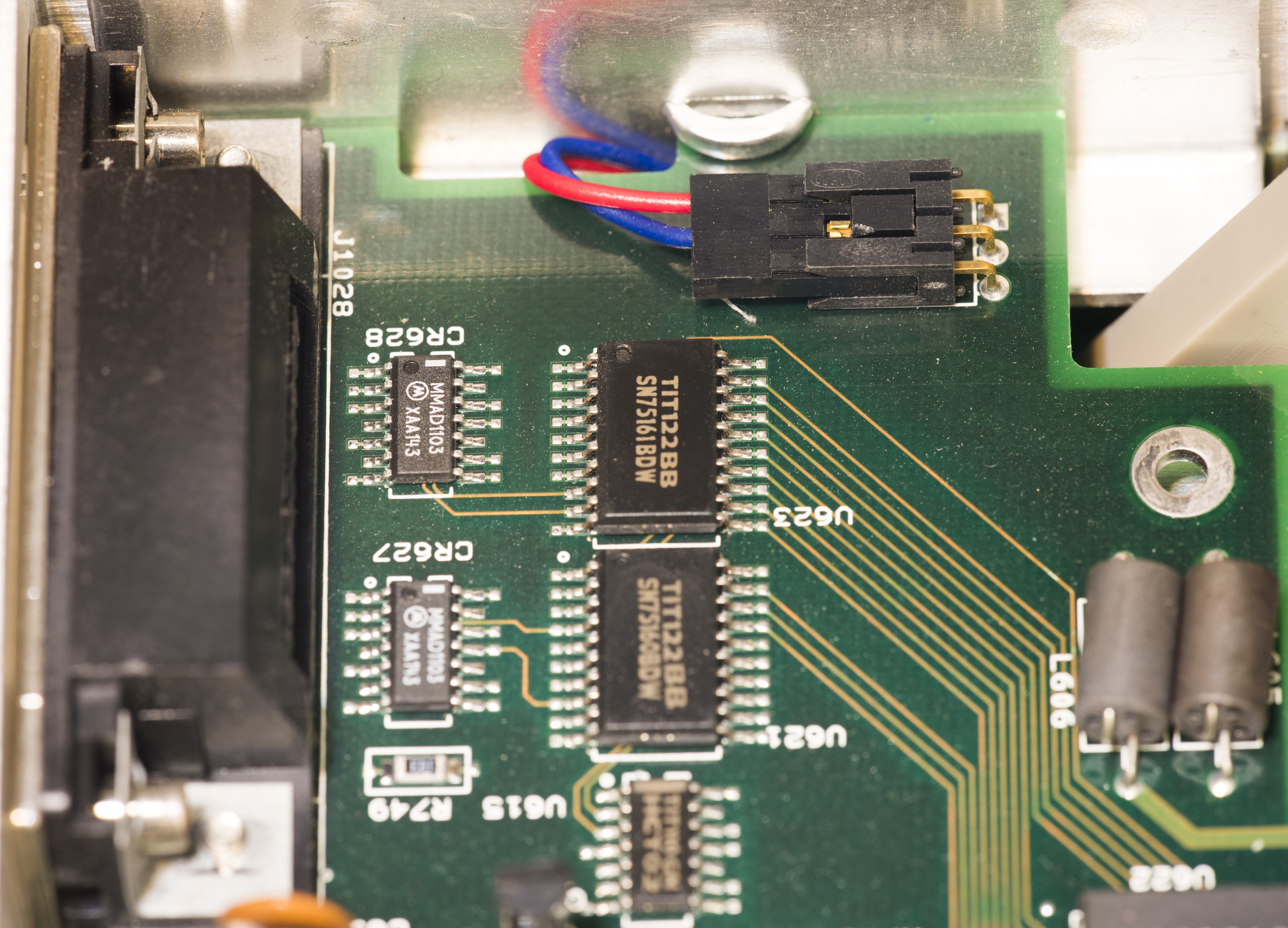
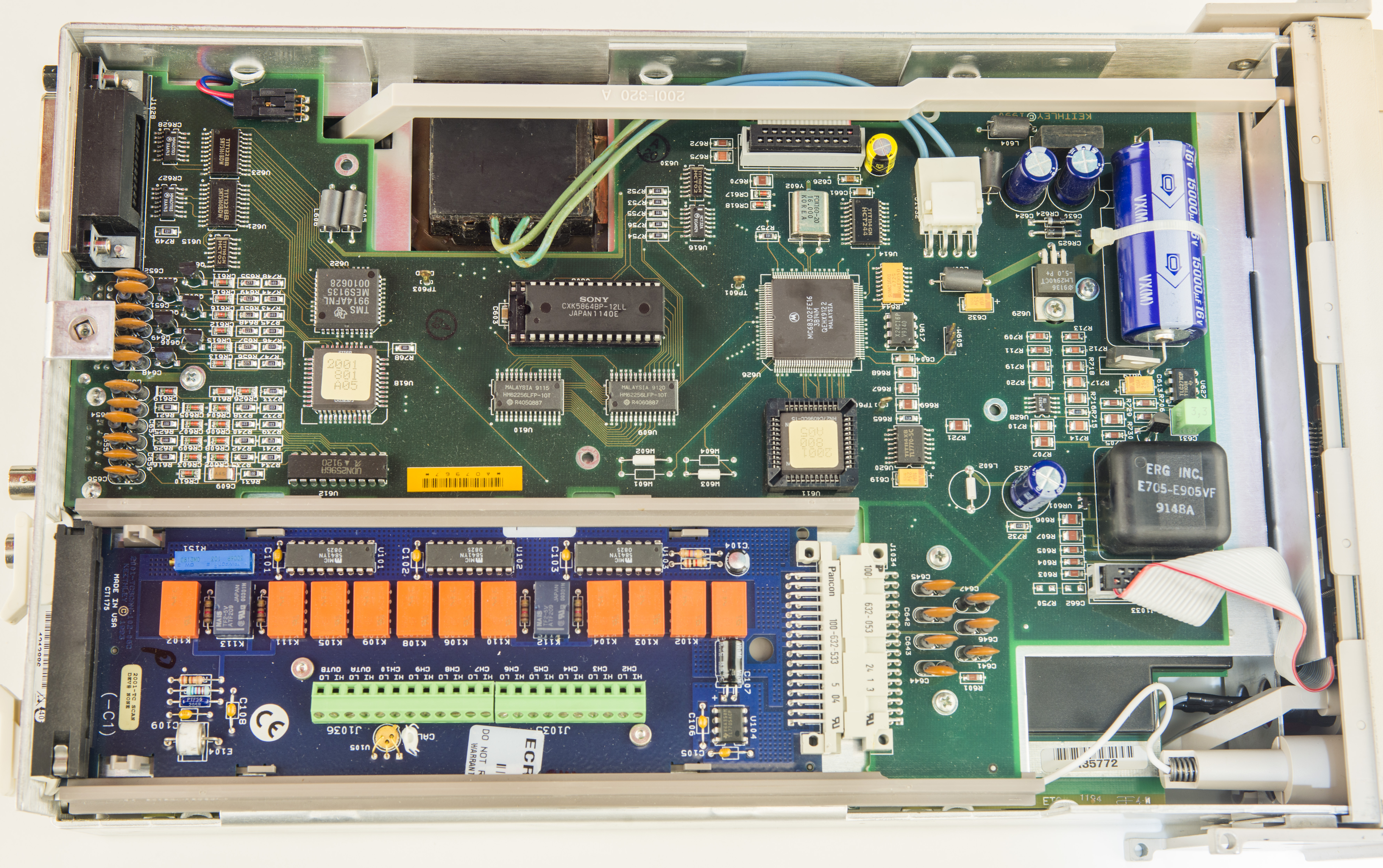
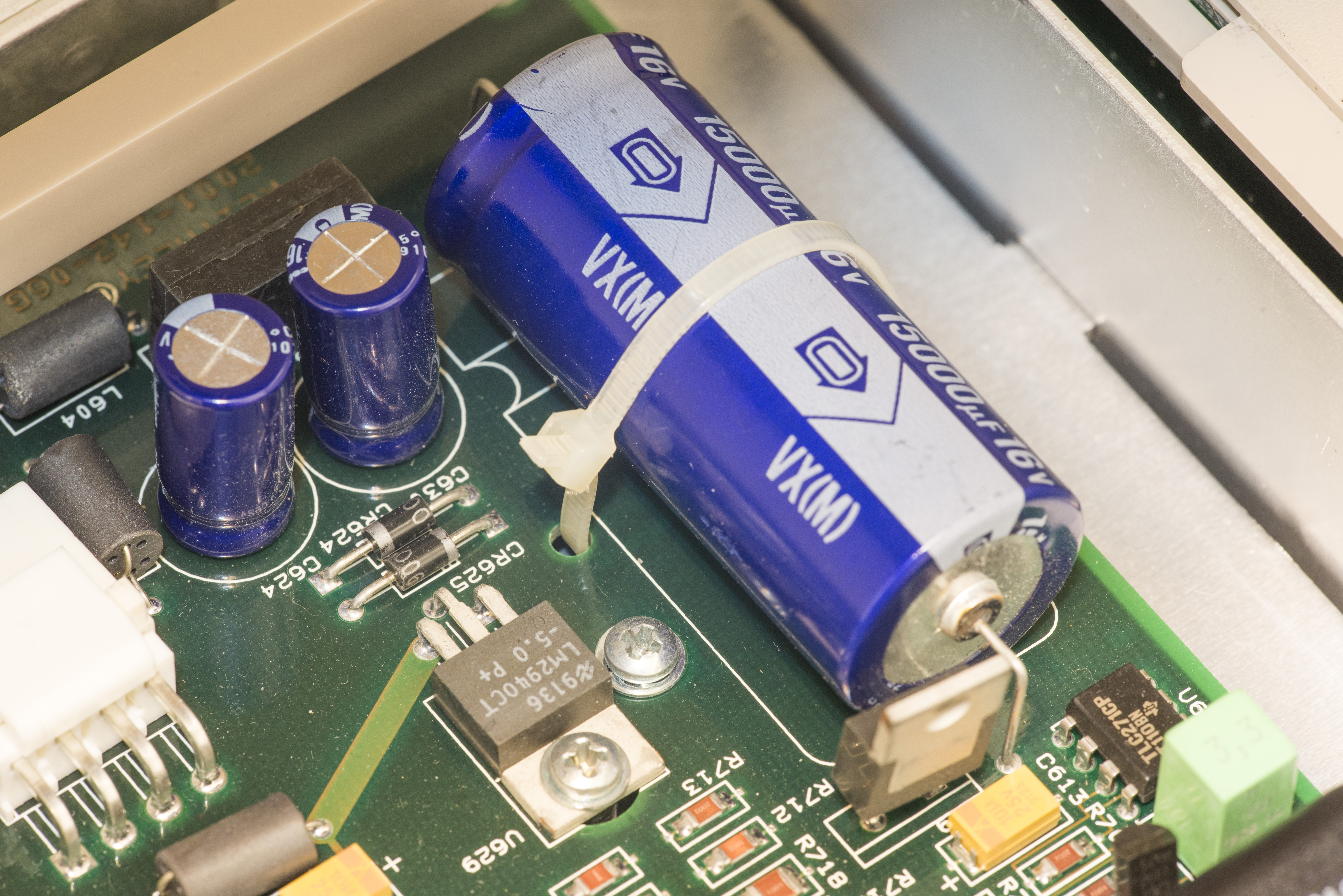
Internal structure and block details
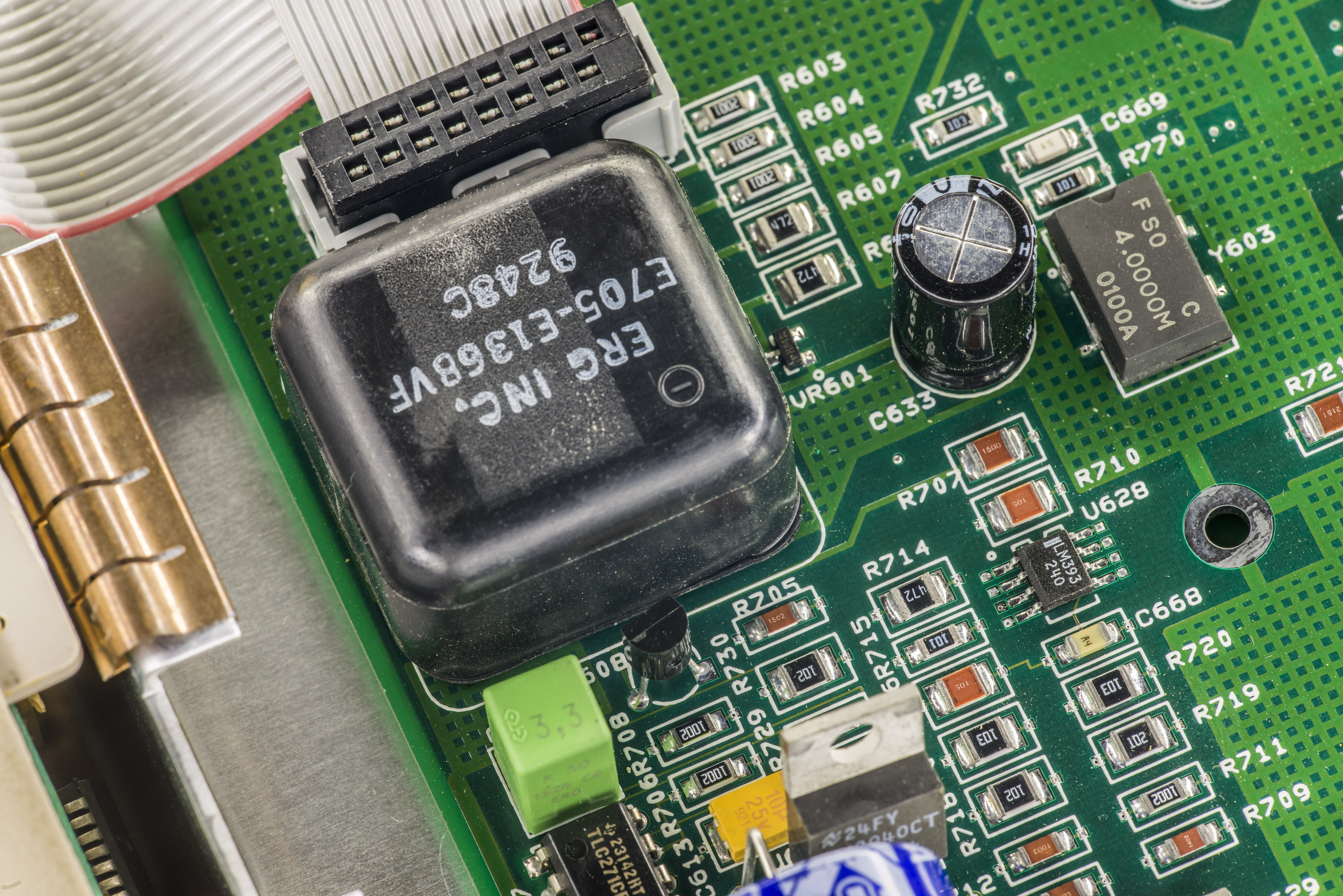
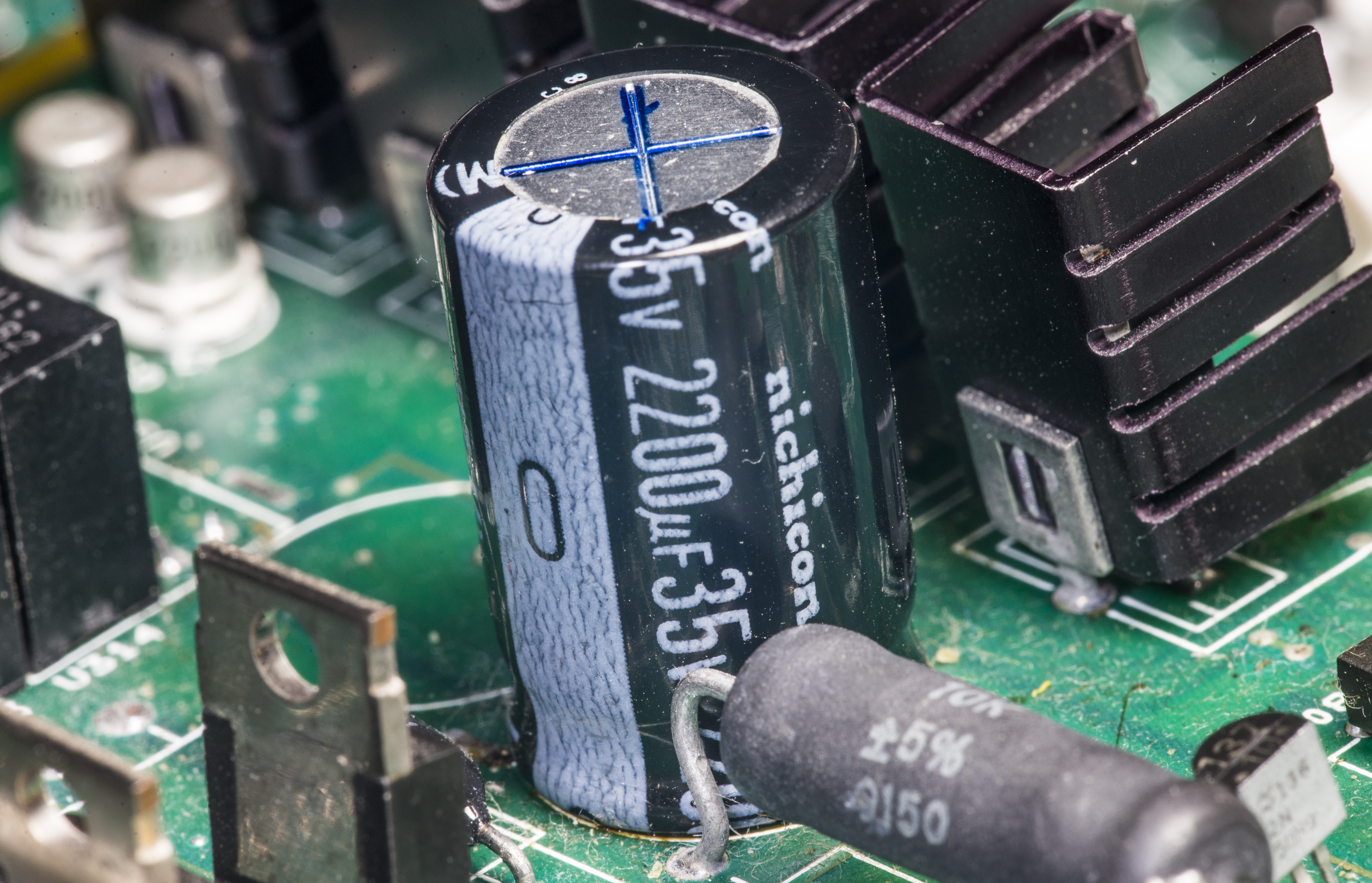
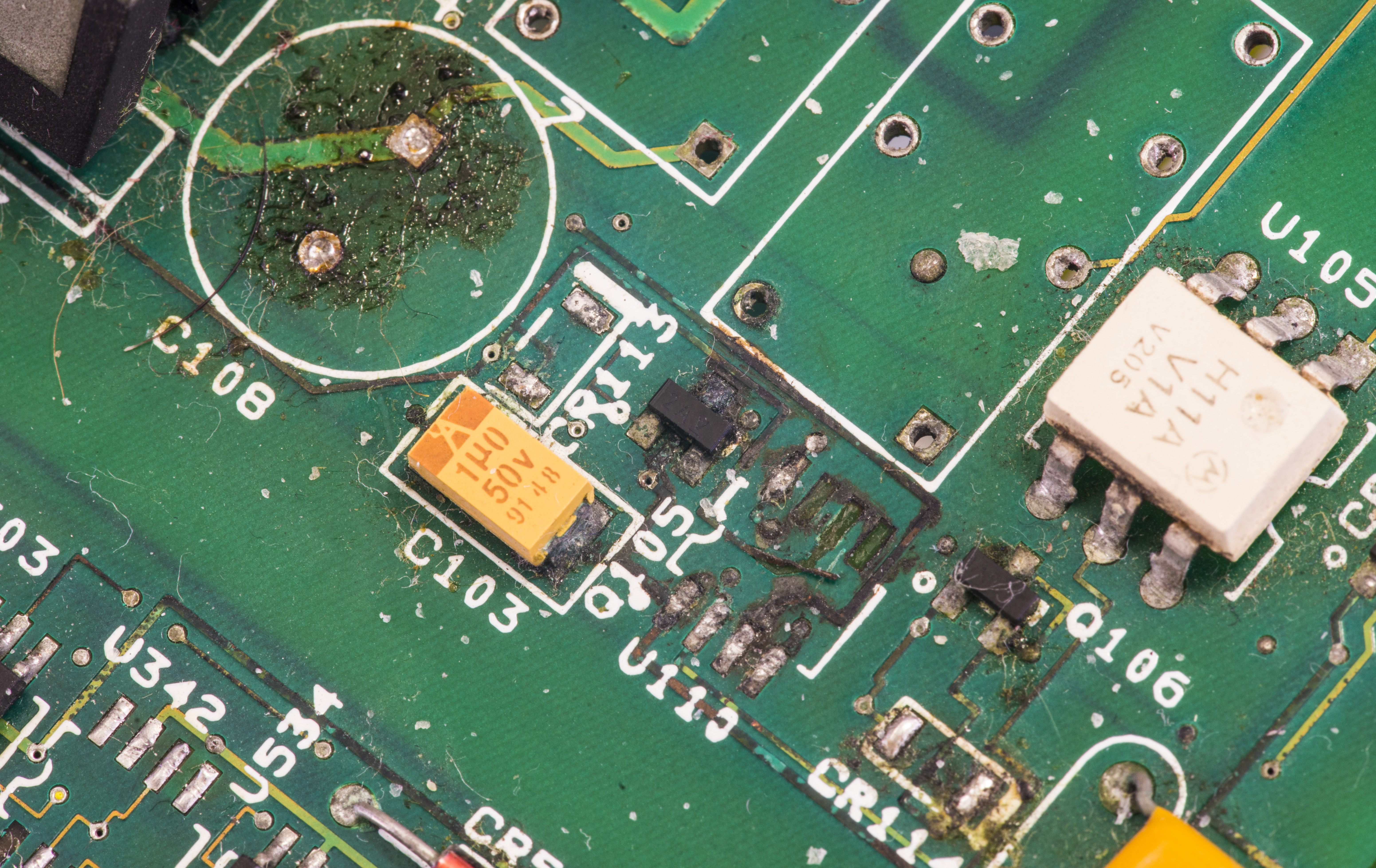
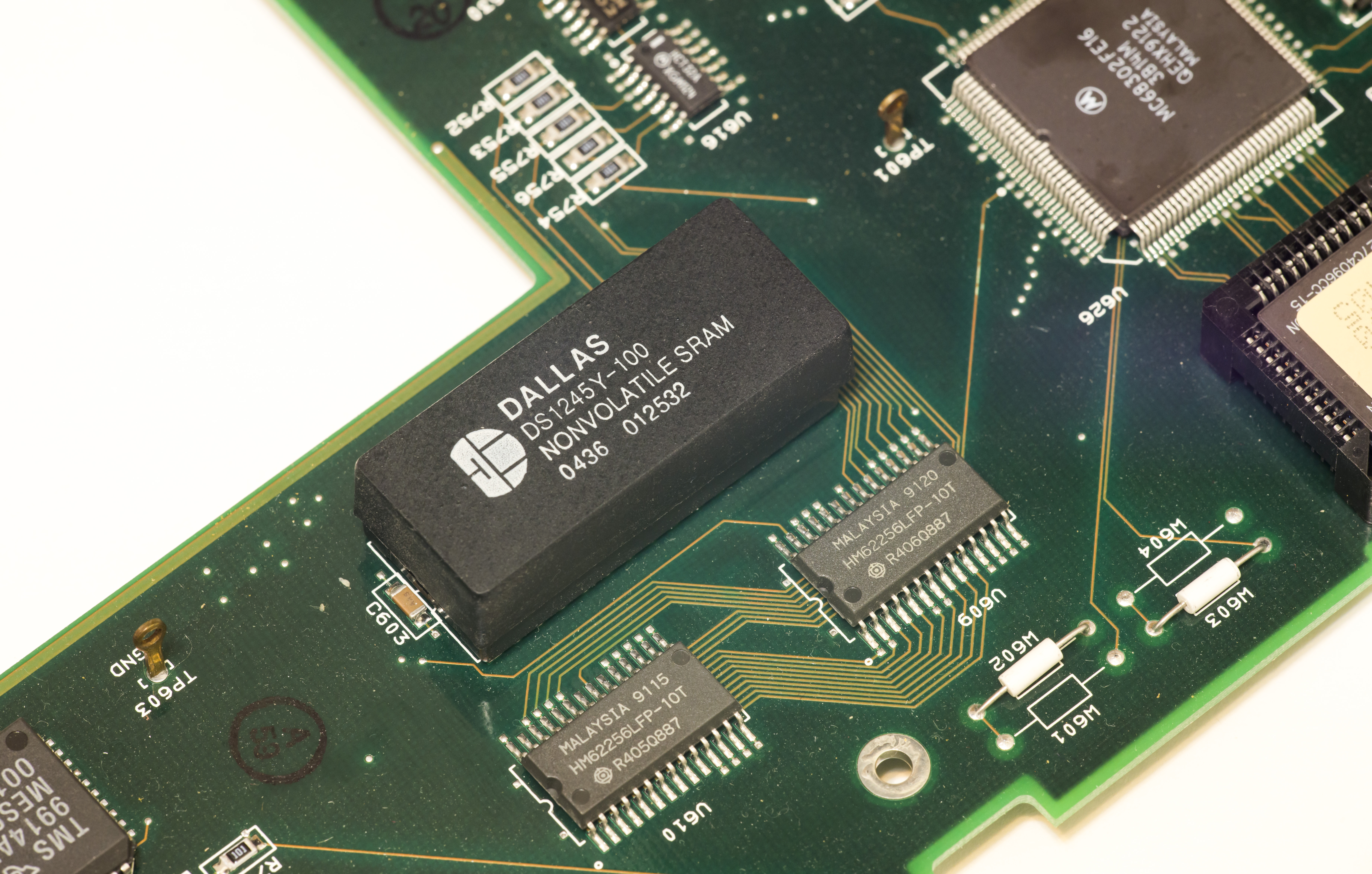
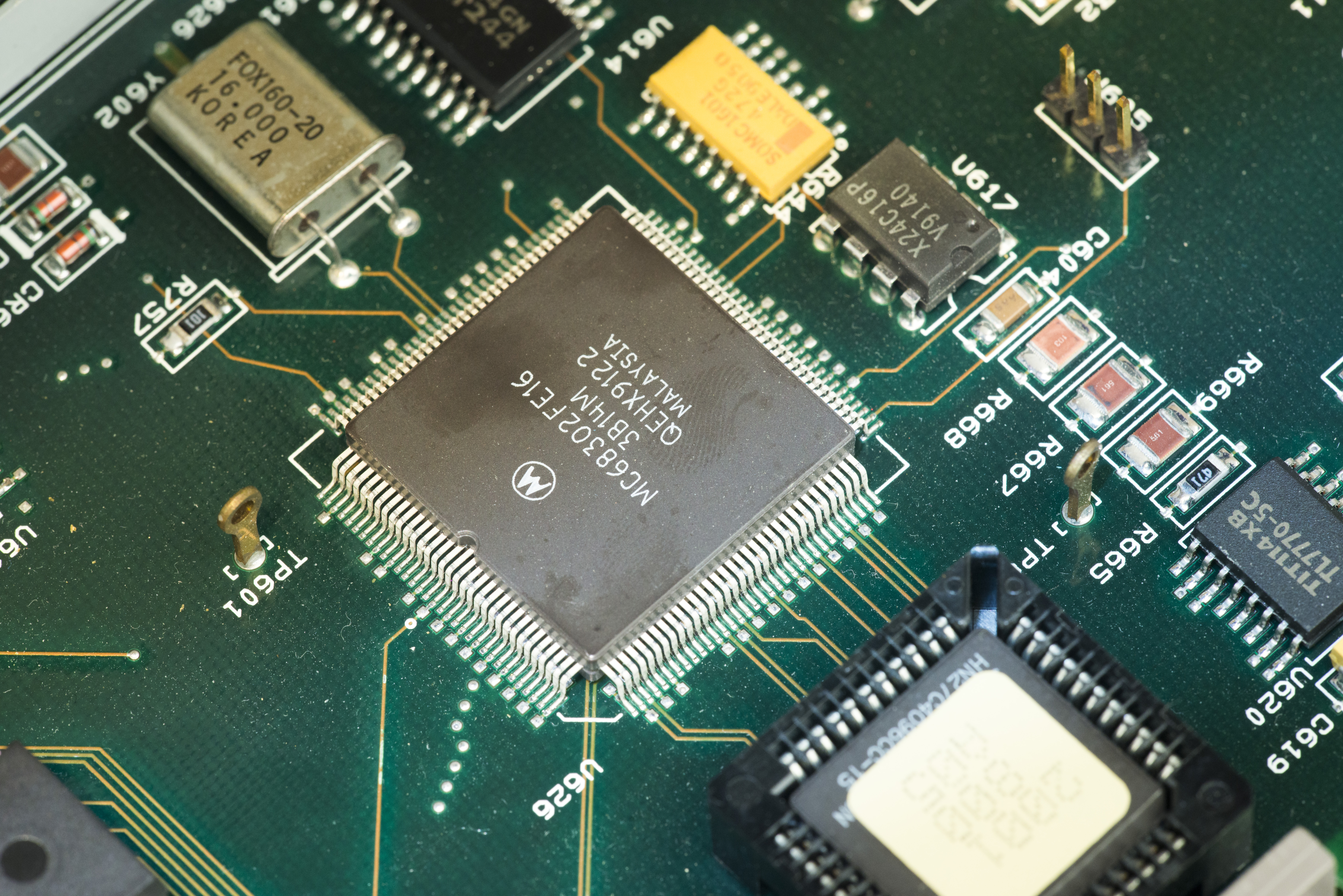
Detail closeup for components on digital board:
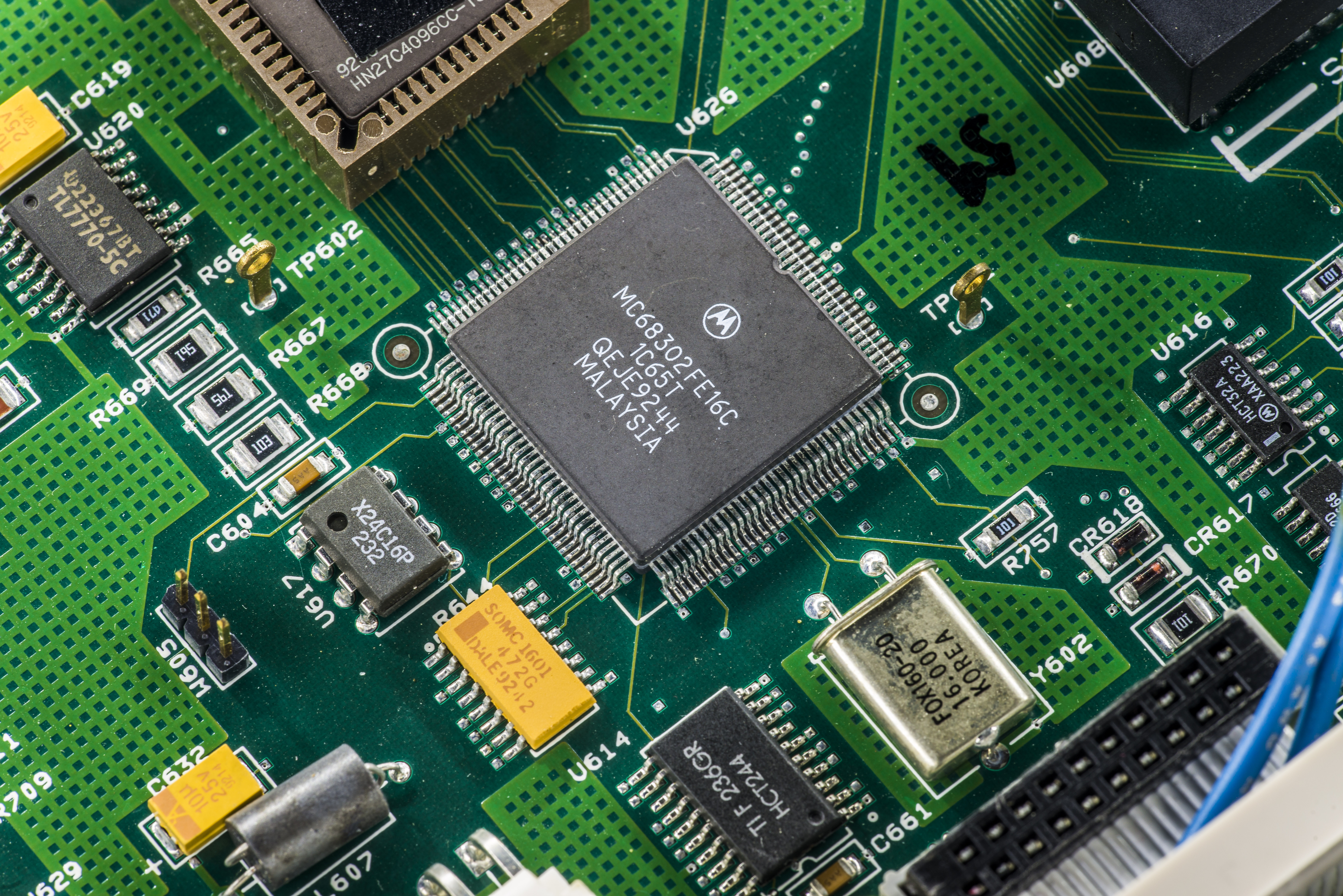
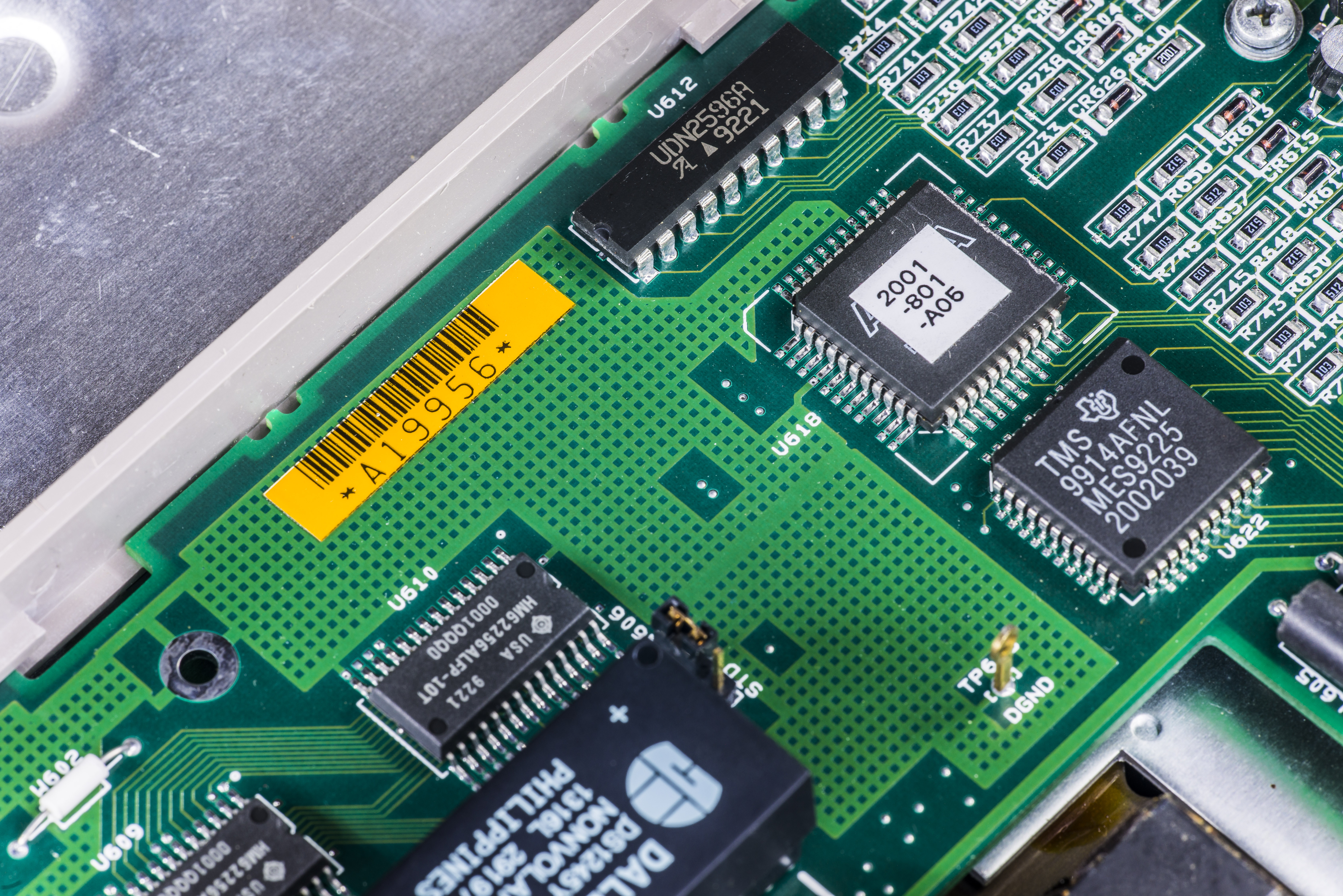
ROM chip:

Overall Keithley 2001 repair procedure
Based on repair experience of no less than seven (yes, that’s right, 7!) DMMs I had my hands on and lot of feedback from other Model 2001 owners, general methodology for this DMM repair fits procedure below very well:
- DO NOT turn meter on first, to avoid more damage, take it apart.
- If your meter more than 8 years old (check date codes on ICs), it is imperative to replace ALL electrolytic capacitors on BOTH analog and digital PCBs. This is first step, do not omit it, or more damage to parts and fragile 4-layer PCBs will occur.
- Clean any corroded traces, carefully check and restore bad vias and connections around leaked capacitors. Make sure no pads or traces are broken/open on PCB. Sometimes trace is eaten inside and damage is hard to see,
- Check avalanche diodes and CR513, CR514 zeners in bootstrap power supply section
- Replace 40×40mm 12V fan, if meter is old. Clean air filter to have nice airflow.
- Now after all power damaged parts checked and fixed, try to power on meter and probe supply voltages (+5, +15, -15, +38, -38, etc). Keep an eye on parts, make sure nothing get scorching hot.
- Run SELFTEST diagnostics. Some of errors and their solution in my case were presented below in article.
- If you have many 4xx.x series errors check U520 and U525. These op-amps have floating power and can be damaged from bad capacitors in doubled voltage supply.
- Check front/rear inputs switch. If it’s dirty or does not actuate well, remove switch from PCB and carefully clean it. It’s serviceable, but be careful with contacts, easy to damage.
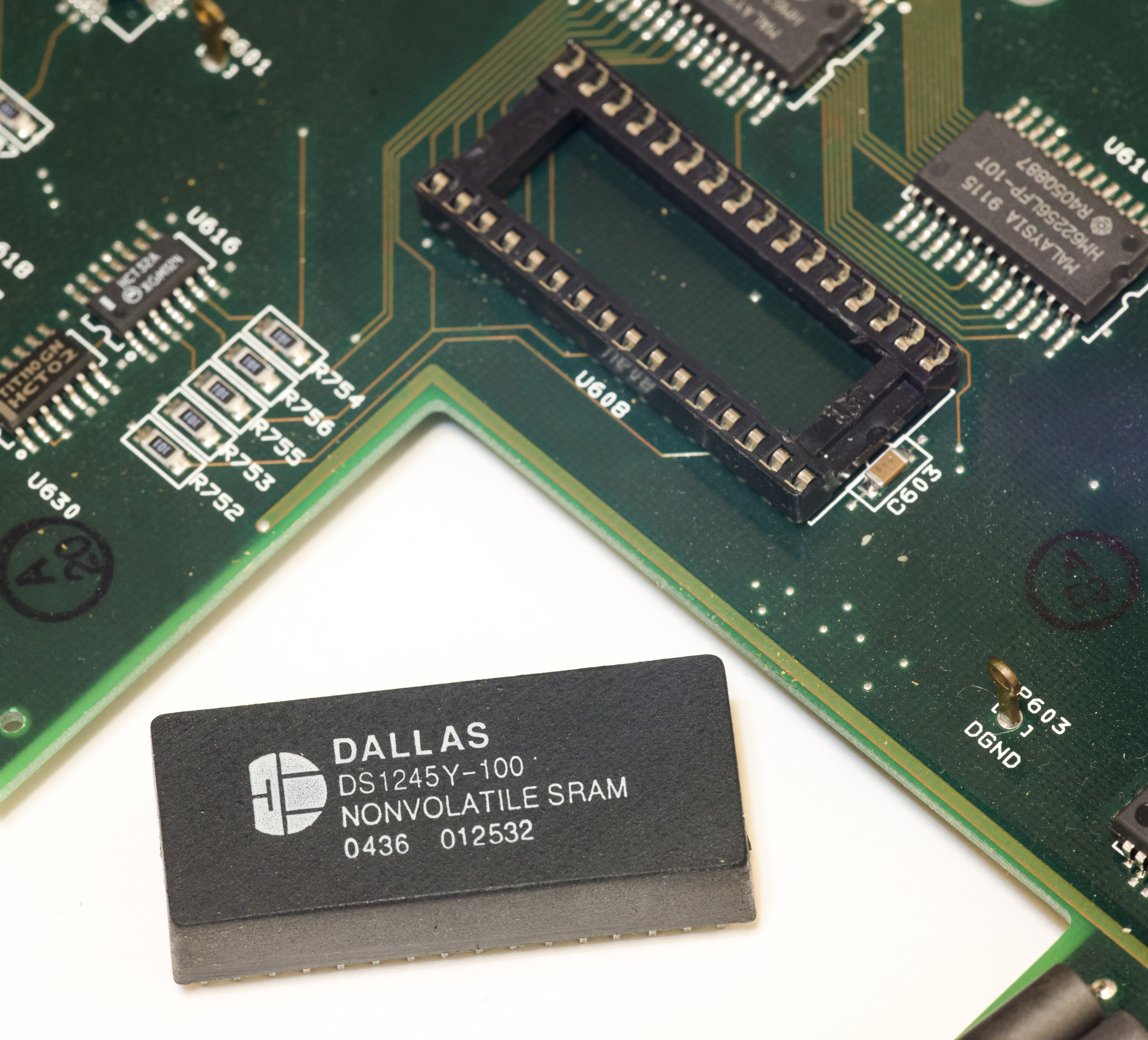
- Backup your ROM firmware and calibration EEPROM (24C16 on digital board).
- You will need stable and known 2VDC, 20VDC, 19-20k&Omega and 1MΩ standards to do user calibration Model 2001
Below I’ll cover repair example and worklog on four old meters, covering most of common issues with these old units. There are multiple PCBA revisions over the years exist in these multimeters, but most of work will be done covering Rev.J and Rev.L.
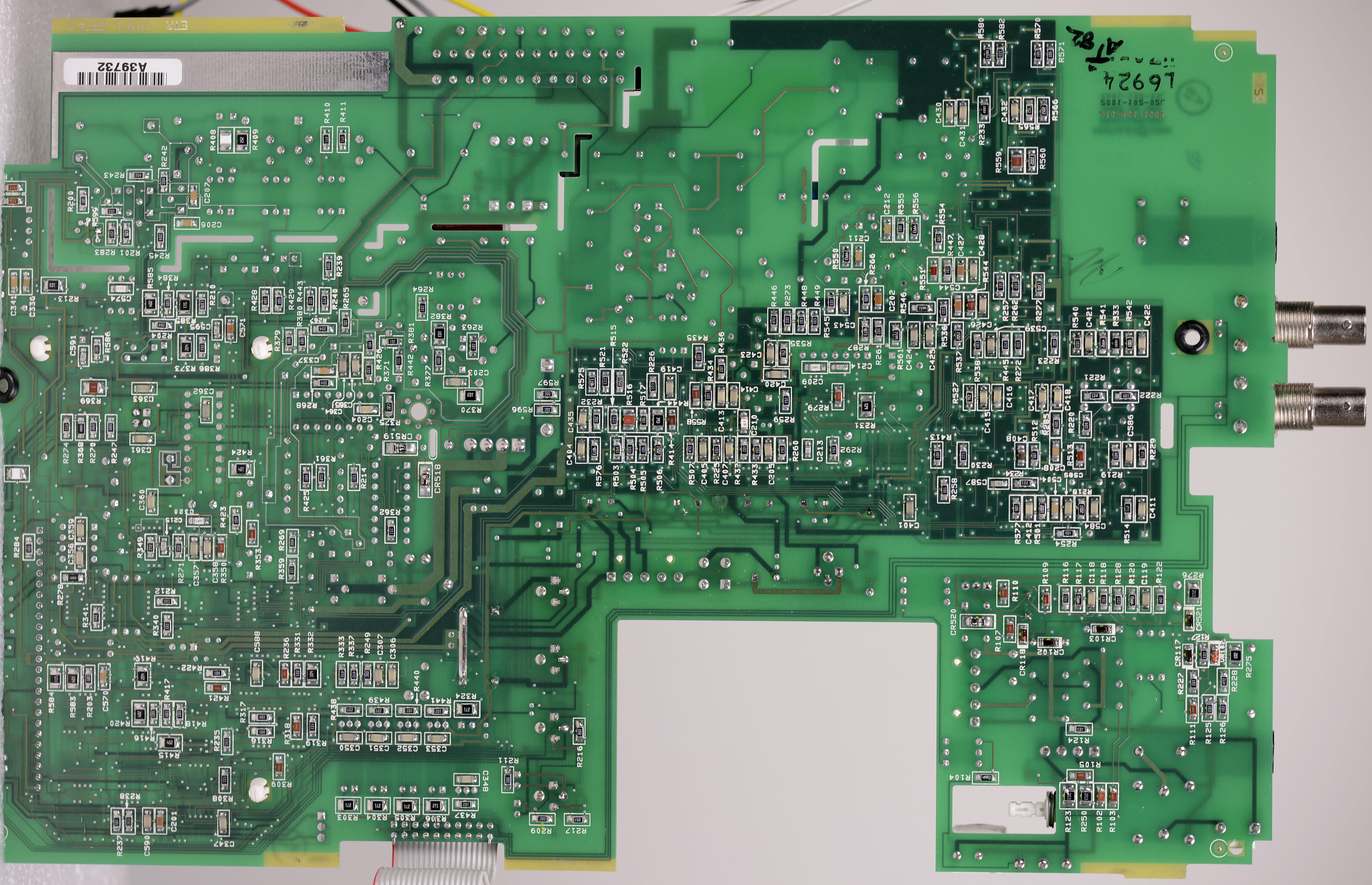
Transparent imaging of Keithley 2001 analog board
I wish I’d had this image back in the years when fixing my first Keithley 2001’s. But better be late then never, so hopefully for people still playing with Keithley 2001’s today this would be useful. Be sure to click on the image to open the high resolution version. This image was stitched together from 8 smaller segments, so some small artifacts might be present on the seams here and there, but I tried my best to keep all traces accurate to layout.

Some parts were removed as this was the image from the donor 2001 board used to steal parts to fix some other 2001 and 2002’s.
Unit #1 repair section
This meter is the one I bought first. It had same issues with leaked capacitors in voltage multiplier, bad avalanche diodes and PCBA damages on analog board.
After replacement of these parts and all electrolytic capacitors, issues with DCV and OHM functions were resolved. This was also confirmed by passing all 3xx.x series tests in self-diagnostics. But ACV, ACI and DCI modes are faulty. ACV reporting presence of 480VAC on 750V range, overflow on lower ranges and incorrect readings on current measurement as well, except DCI 2A range.
Many 4xx.x tests we failing in self-diagnostics.
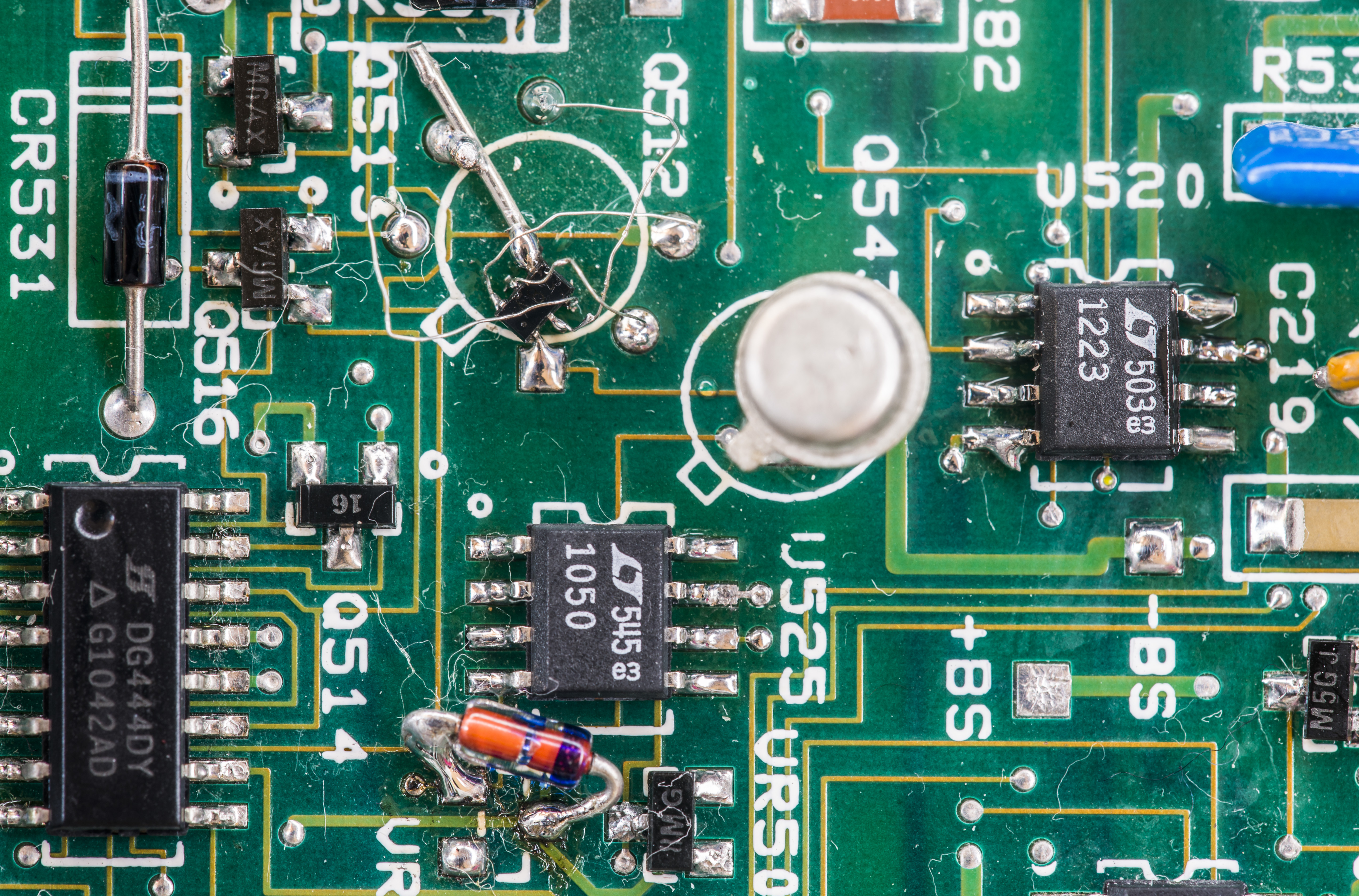
After few days of troubleshooting culprit was found in Linear Systems U441 dual JFET pair in floating FE circuitry, causing current mirror to become unleveled and failing all related tests and operation. U520 had incorrect drive due to one of JFETs in Q512 gone bad. Temporary replacement with NXP PMBFJ620 in SOT363 corrected the issue and meter was happily passing SELF-TEST routines. Both parts are marked in red on schematics:
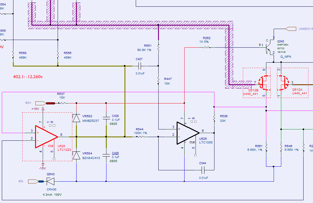
Rework was not pretty, as original Linear Systems U441 is in hermetic TO-71 6-lead package, while PMBFJ620 is tiny SOT-363. I have new U441 on it’s way to make it right later.
Hangs/No comm link error after warm-up
Two of repaired meters had issue related to digital section. After initial warm-up, which took 15-30 minutes, meter’s digital circuitry hang, not responding to any keys. After power cycle meter was unable to boot, and front panel had just “No comm link” message displayed. This happening when main processor unable to send any commands to display board MCU.
I checked power supply on digital board, which is only +5VDC from separate transformer winding, rectifier bridge, it was all fine. All electrolytic capacitors were replaced before hand, so it’s not them.
Issue on one unit was discovered to be bad NVRAM chip, Dallas DS1245Y. It was one of the chips bought from eBay, and with removal of memory option (leaving socket empty) – 2001 had no more issues even after 24 hours of operation. As DS1245Y is sitting on same memory bus as main SRAM and ROM, if it have intermittent faults it could corrupt processor data bus causing hangs.
Unit #1 calibration section
Unit #2 repair
This 2001 was bought broken, as for parts. Initial inspection indicated there were missing critical parts and damages, as shown in chapter below. Also there was no A/D converter board, so we had used spare board bought separately.
Analog board (Rev.L)
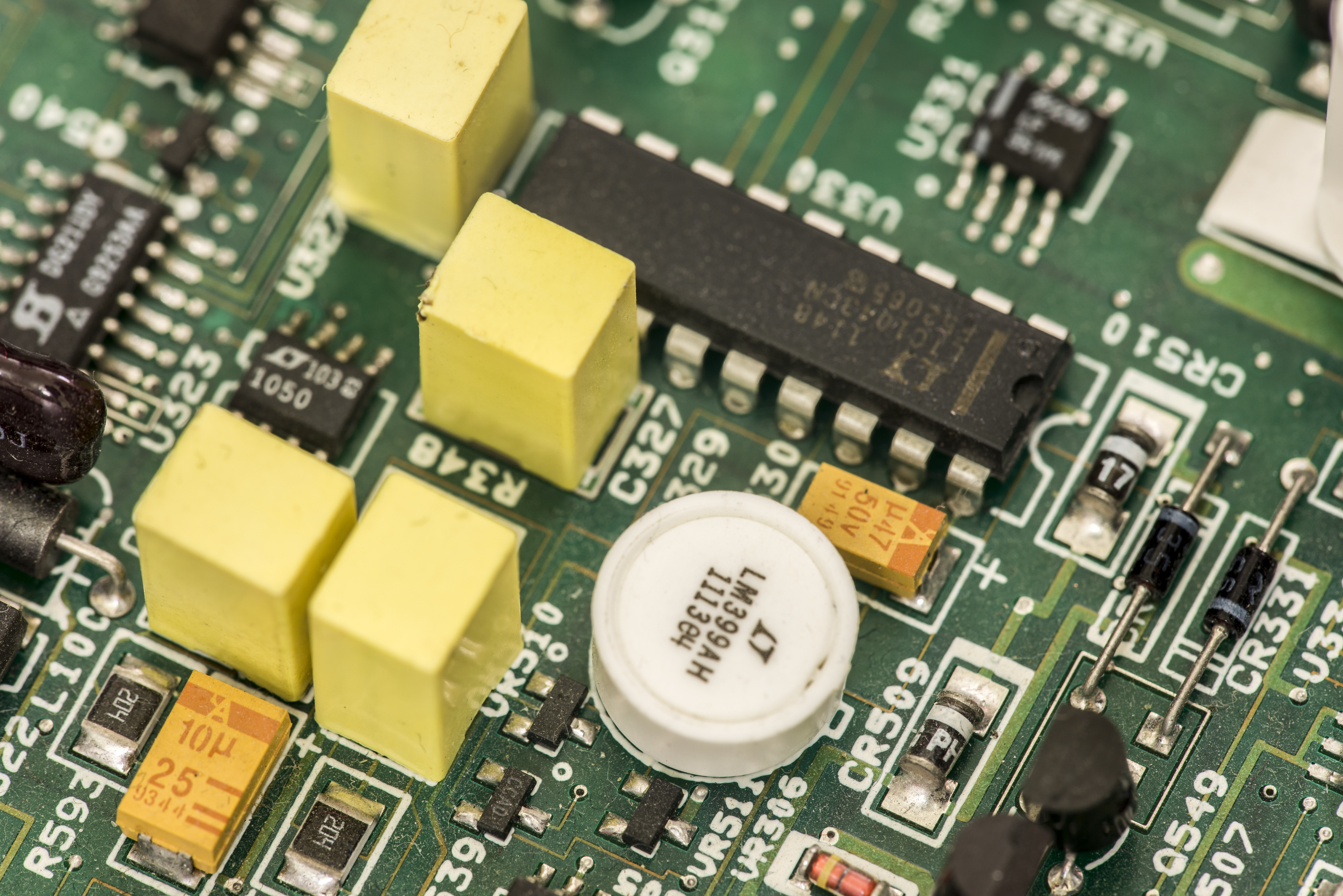
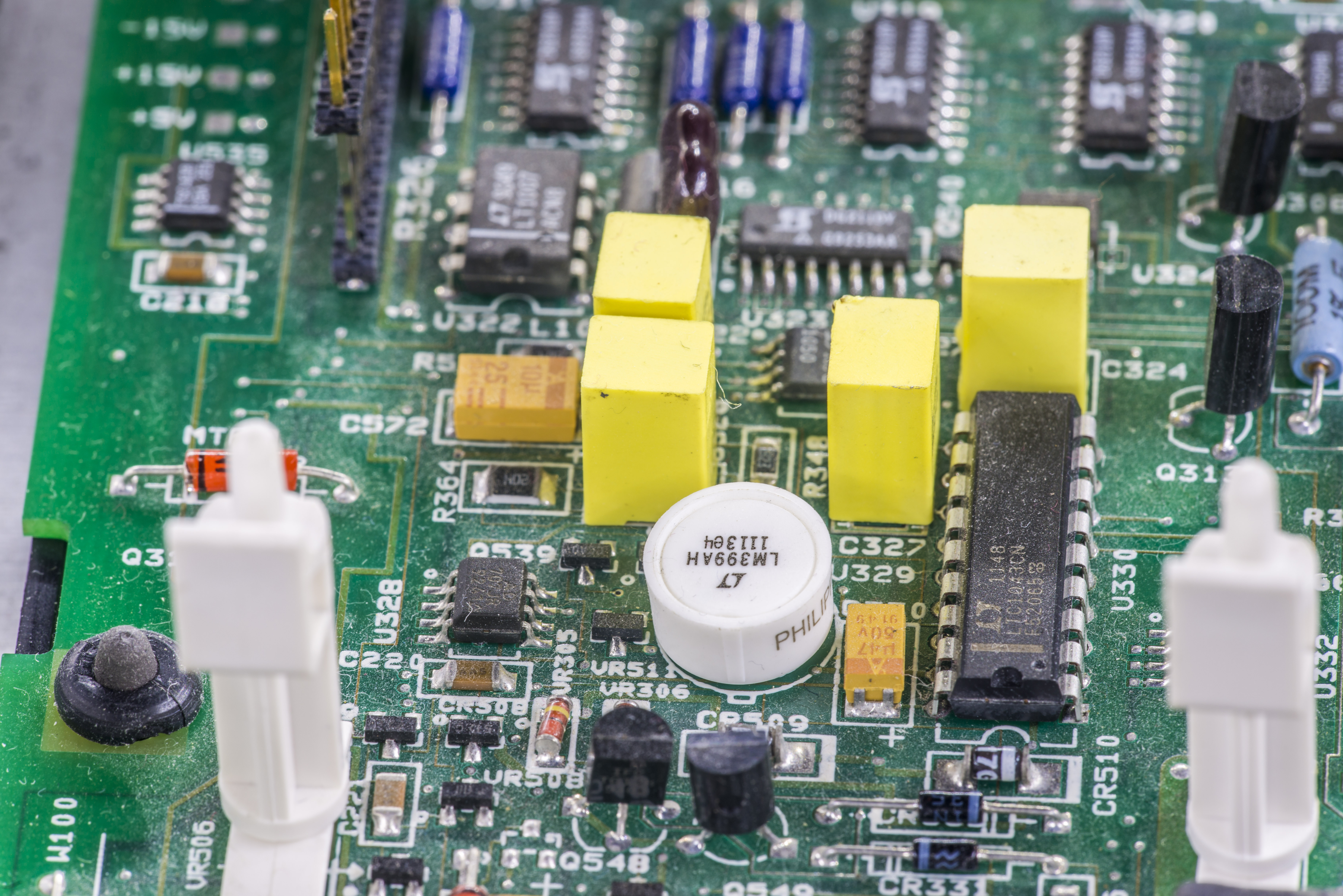
Missing parts were located around voltage reference:
| U329 | 196-600A | IC, PRECISION REFERENCE | Linear LM399 | Precision ovenized 7V voltage reference |
| U330 | Linear LTC1043 | Capacitor switching block | ||
| U327 | Linear LT1050 | 1.75V reference output opamp | ||
| Q540 | BT3904 | NPN transistor |
| Q330 | TG-254 | TRANS, DUAL N-CHAN JFET, IFN146 (TO-71) | Matched JFET |
| Q512 | TG-235 | TRANS, N-CHAN. DUAL JFET, U441 | Matched JFET |
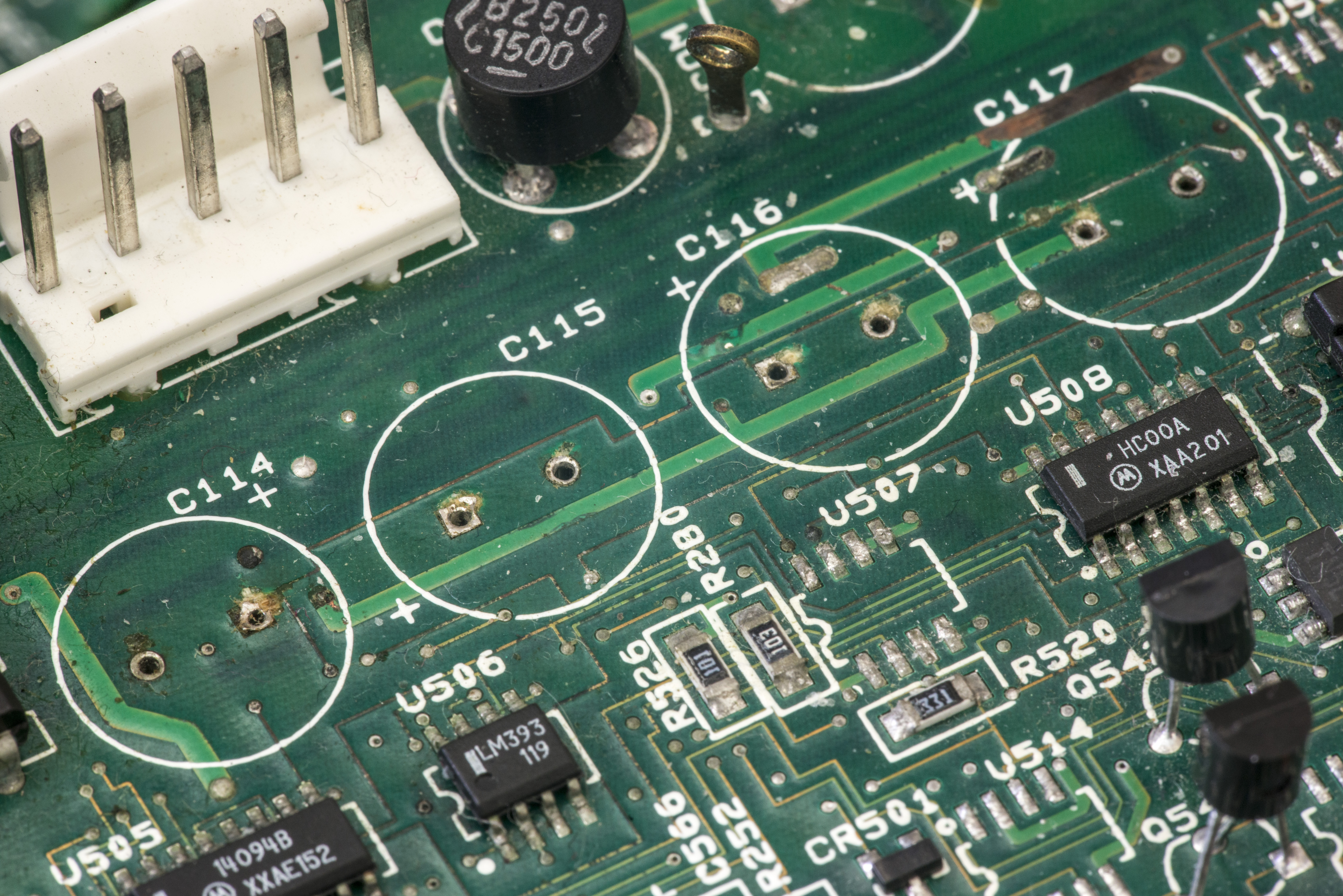
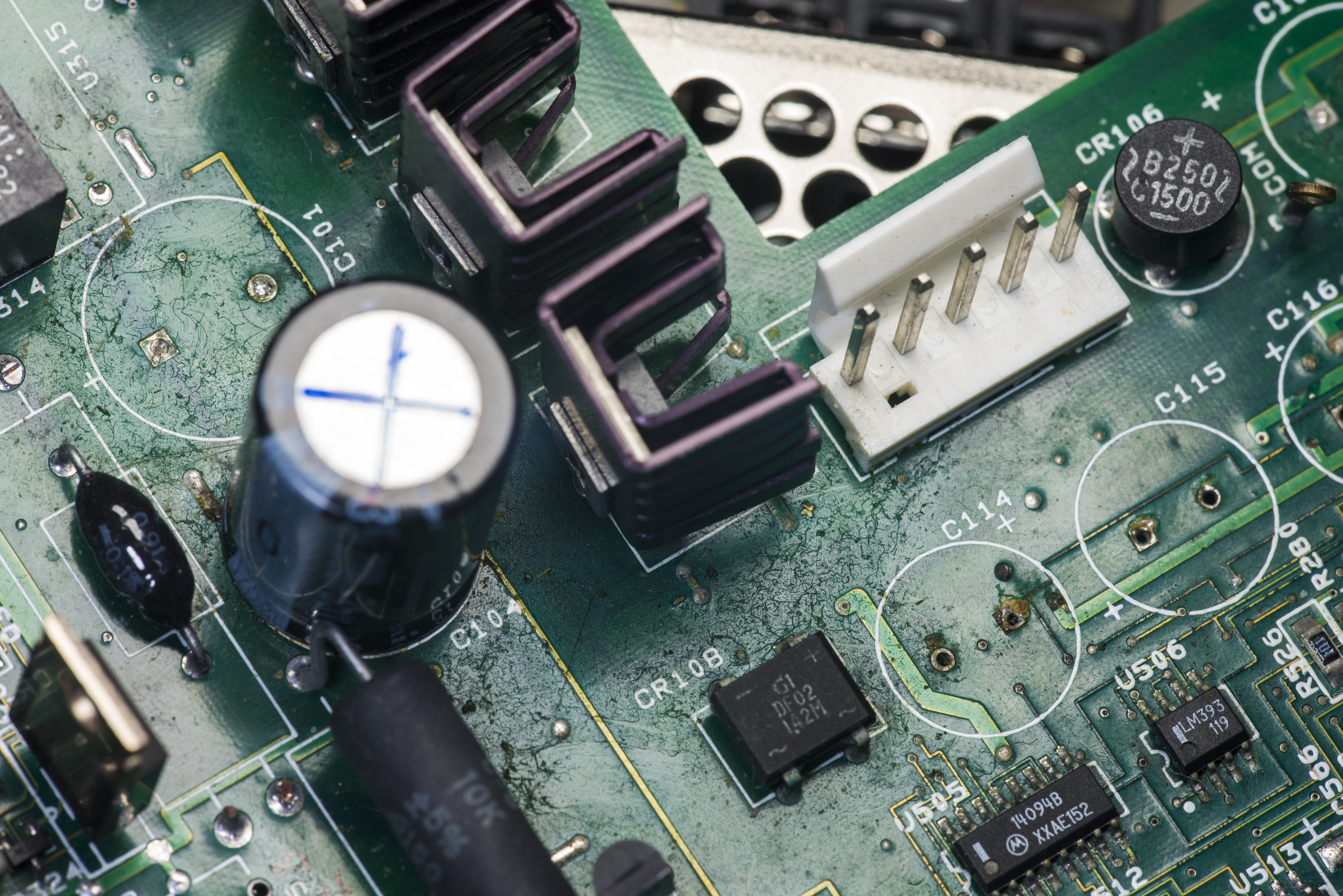
Previous owner tried to fix by putting wrong diode on CR111 :(. And as lot of old Model 2001 units this one had issues with leaking caps and damaged PCB around bootstrap capacitor supply nodes (capacitors C114,C115,C116,C117 and avalanche diodes near them).
Rest of board look OK, but likely to have hidden damages in some parts we don’t know about just yet.
Overall board photos for both sides:
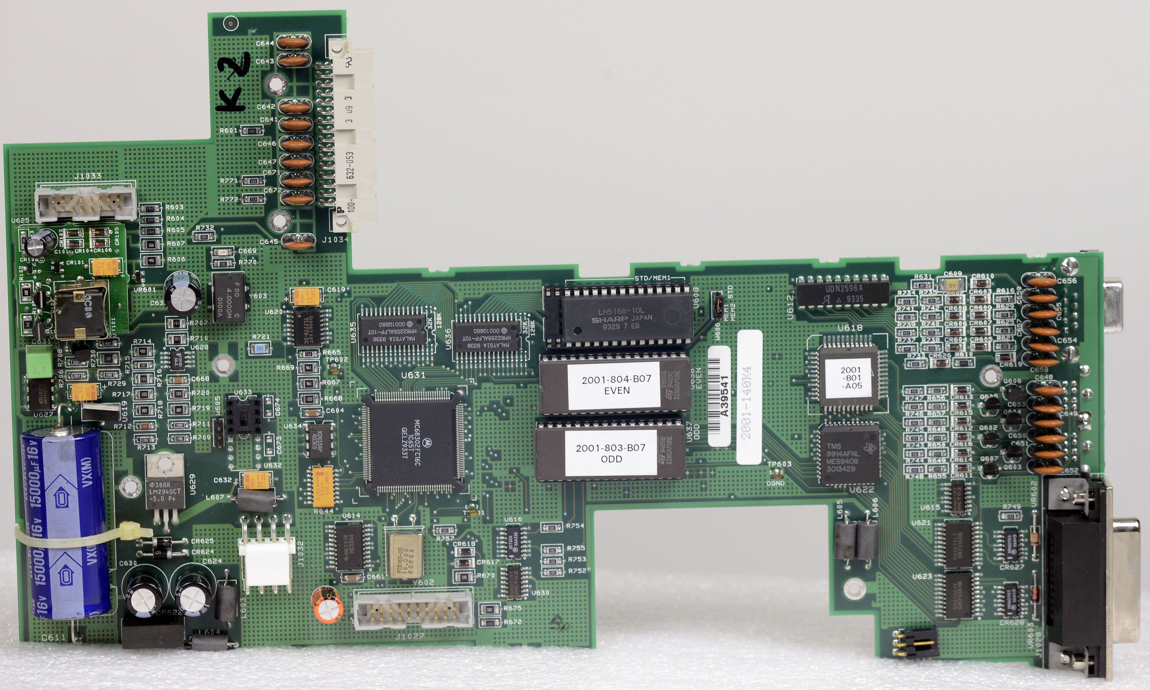
Digital board (Rev.K, same as used in Keithley 2002 units)
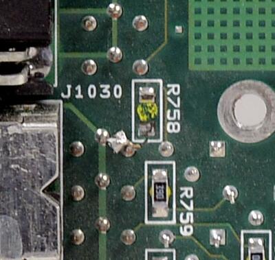
Missing R758 and damaged footprint pad for it
Overall board photos for both sides:
Repair
First step was to get back all parts. While LM399AH, LTC1043 , LT1050 are readily available either directly from Analog Devices or Digikey, parts like matched obsolete JFETs are way harder to obtain. One of not as straight forward, but rather easy route is to buy another 2001 unit which is beyond repair, as donor for salvaging needed parts. Luckily during that time there was one for sale around 100$ USD with many parts missing on analog boards, but it had these Q330 and Q512 JFETs on it. So I got this, already third, meter just to donor parts.
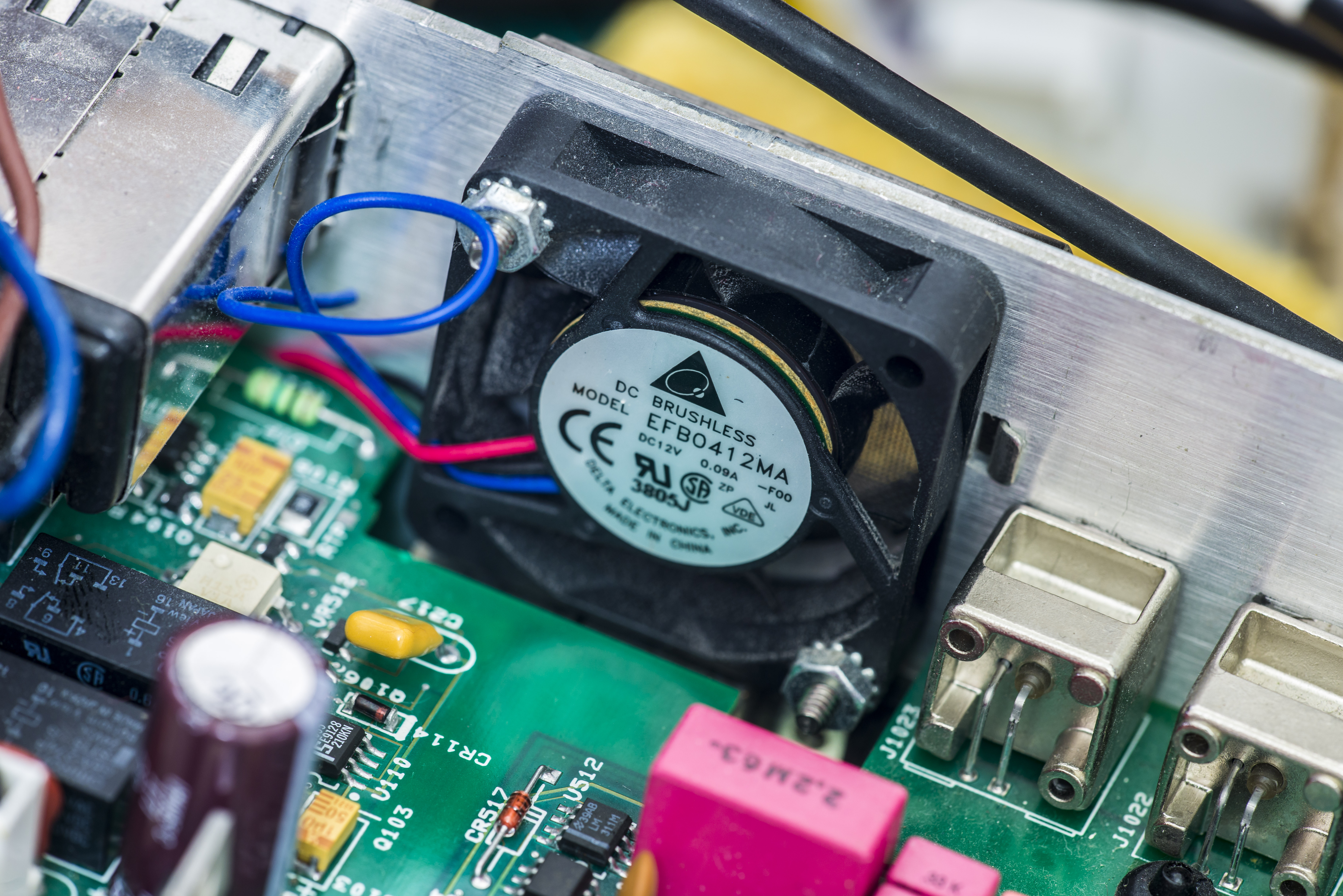
First thing to do servicing old Model 2001, is to replace fan to fresh new one, to avoid overheating and capacitor life reduction. In this case new Delta EFB0412MA (40×40 mm, DC 12V, 90mA) was installed. Also ordered and installed capacitors, missing parts, such as voltage reference:
And capacitor block, Q330, Q512.

DIP holes for LTC1043 are easy to clean using copper solder wick. Be careful not to overheat PCB, since this 4-layer board don’t have solid copper polygons on inner layers and easy to delaminate from high temperature exposure. ERSA iCON soldering station with temperature set to +275°C.
Install 2001-162 Revision H A/D converter board

Now after check for shorts or open connections, power on unit. It did power on okay, initial check on +5V, +15, -15V, boost supplies +38 and -38V shown no problematic deviation. Since testing function of such sophisticated DMM is not an easy job, Keithley implemented handy self-diagnostics mode, when meter using it’s ADC and internal switches to test for various blocks and compare measured signal with reference value stored in ROM. Running test is easy, by navigating GENERAL/TEST/SELF-TEST menu.
Resulting list of errors is scary-some:
- 105.2
- 304.6, 304.7,
- 401.1, 402.1, 404.1
- 404.2, 404.3, 404.4, 404.5,
- 405.2, 405.4, 405.6, 405.8
- 406.6
- 407.1, 407.2, 407.3
- 409.6
- 410.1, 411.1, 411.2, 412.1
Error 105.2
This was easy fix FIXED by repairing connection for knocked off resistor R758 on digital board and putting 39 ohm 1206 resistor back.
Errors 304.6, 304.7
These were fixed by cleaning PCB with isopropyl alcohol around ohms current source on analog board and range switches very well. On high resistance ranges test current sourced by meter is mere hundred nanoamp, and contamination on PCB surface or dirty component leads can easily upset such sensitive signal path. General rule for handling high-precision PCBA is not to touch anything with bare fingers (as oil and dust from fingers contaminate surfaces and cause unwanted leakages).
40x series errors
Having so many similar errors usually indicates that either power rail or some bias level common for all affected parts/blocks is not correct or noisy. So these situations it’s often viable to use systematic approach, rather than trying to fix each item one by one.
In this case next operations were performed:
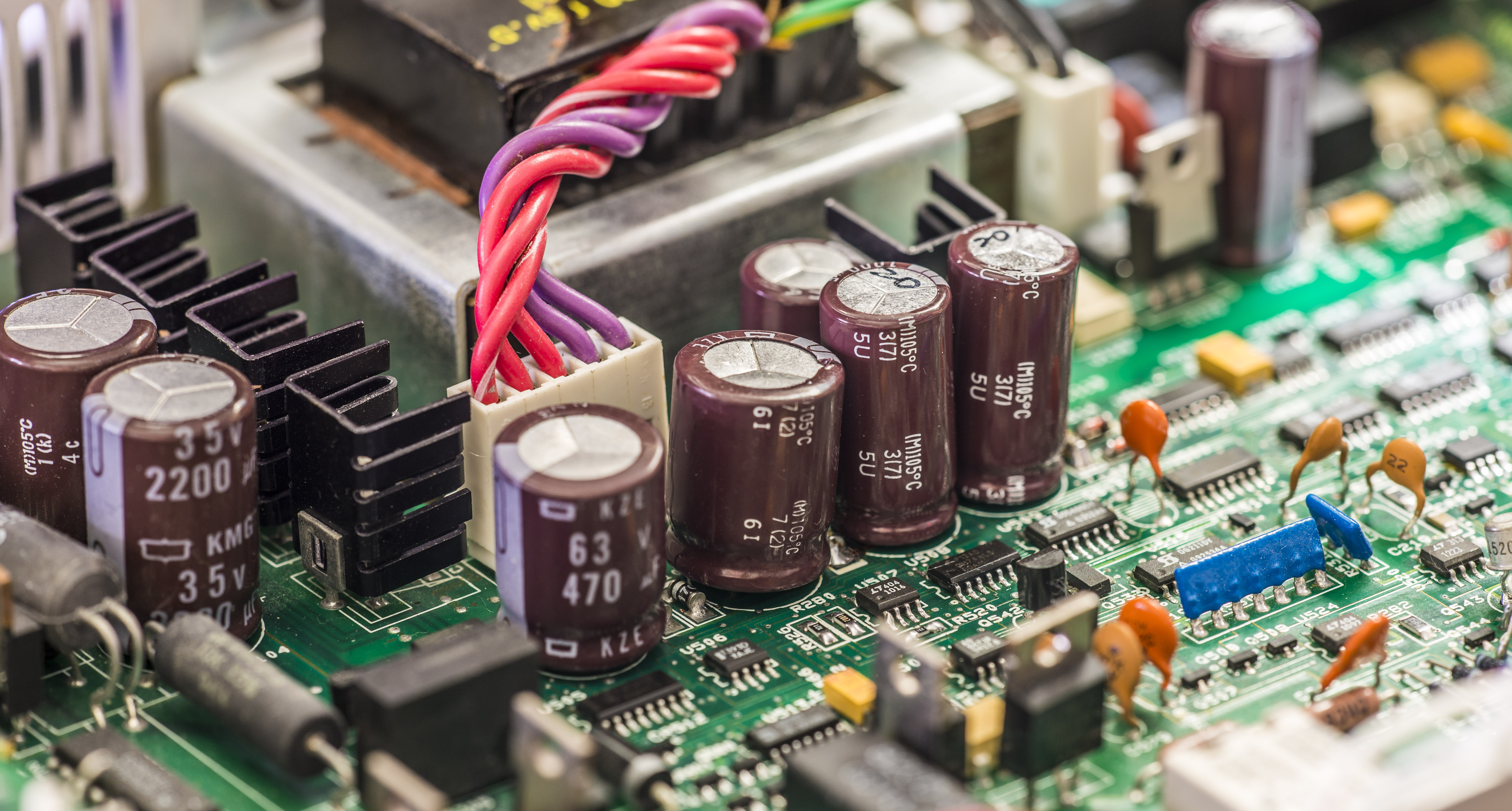
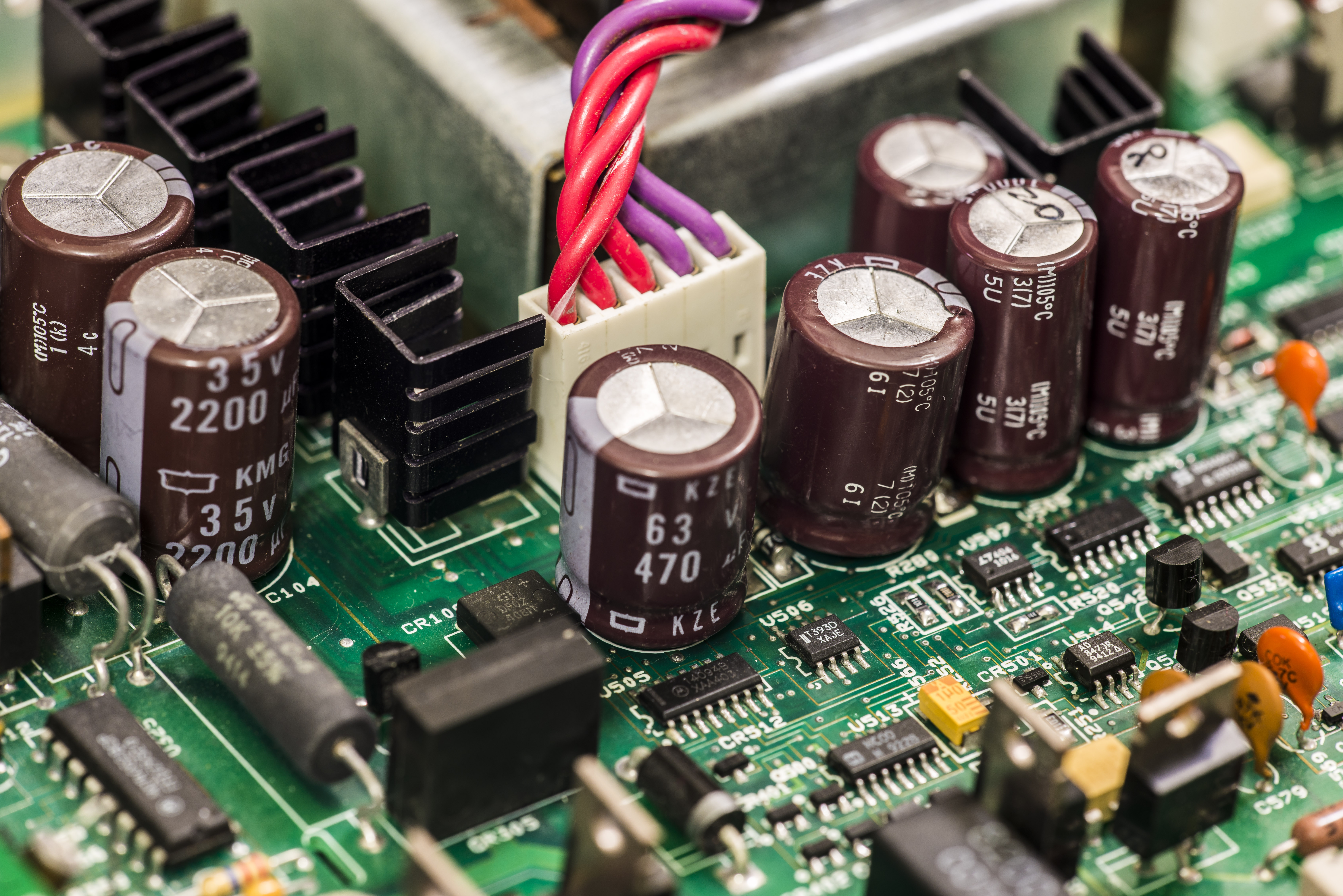
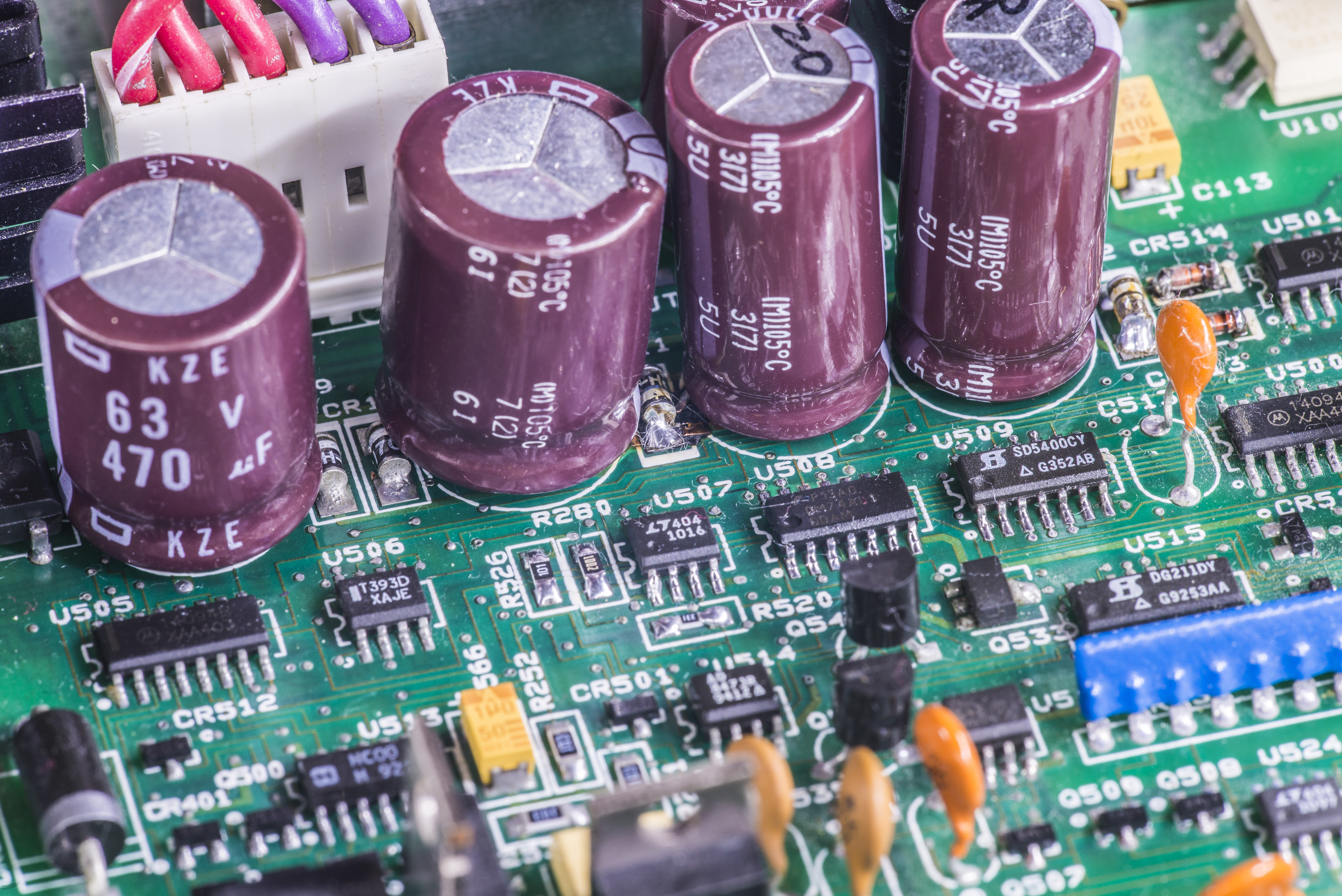
- Install new Chemicon KMG 1000µF x 50V (C116,C117,C108) and Chemicon KZE low-ESR 470µF x 63V (C114,C115) capacitors. KZE caps are bigger so little lead forming and careful installation was performed. C106 was replaced earlier with KMG cap.
- Install correct avalance BYD diode on CR111 location.
- Desolder U507, U508, U509 and clean surface/pads in this area with clean acetone. After cleaning – solder U507,U509 back, and replace U508 to new 74LS00 as it’s just jellybean part and easier to put new in, than testing if original is ok.
- Replace R526 (100R 1206), R280 (10K 1206) and R520 (330R 1206) resistors with new ones, as original resistors had heavy corrosion from electrolyte.
- Replace U519 (donor taken from another unit analog board)
- Replace U516 to ADA4898-1YRDZ opamp. Since this opamp have exposed pad there was capton mylar film placed under package to avoid short possibility to via under footprint.

One of other units with similar 4xx.x errors had bad U525 and U520. Diagnostics on that meter revealed function issues – DCI measurement on ranges other than 2A was throwing some incorrect readings even with short on inputs, ACV was showing fixed 480VAC on 750V range (with no input signal/short) and overflow on lower ranges and ACI currents.
Issues fixed after U525 and 4.3V zener replacement. Original LTC1050 opamp had leaky resistance 145Ω between V+ and V- rails making low-power floating supply circuitry unbalanced.
Other meter had bad LT1223 current mode operational amplifier, driving FET full-wave rectifier bridge to -12V, and screwing everything. Same dianosis errors and ACV,DCI and ACI function failures were observed. Removed U520 and powered meter without it, supply voltages on U525 become normal.
Now assemble unit.
After successful power on, we can run self-test again.
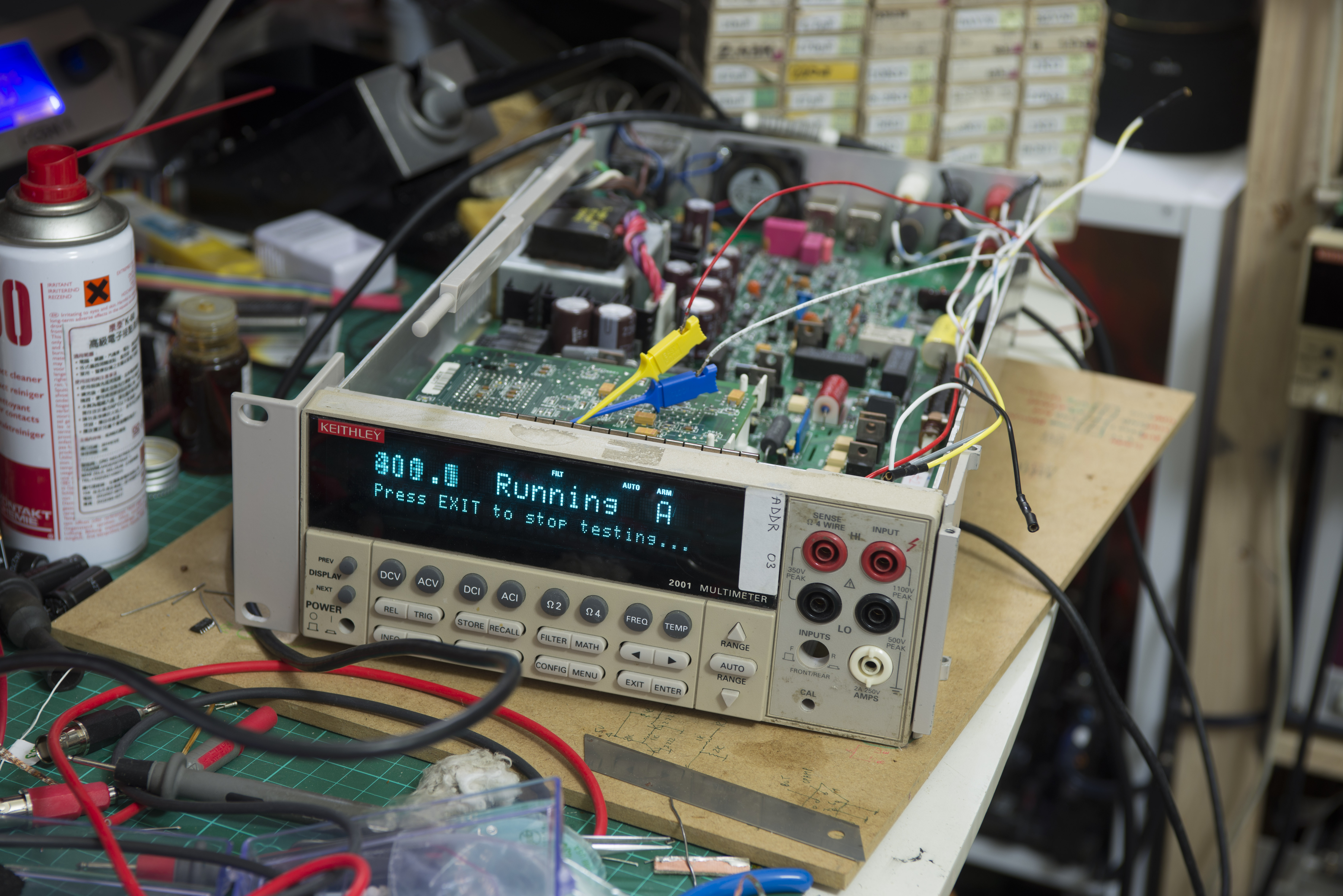
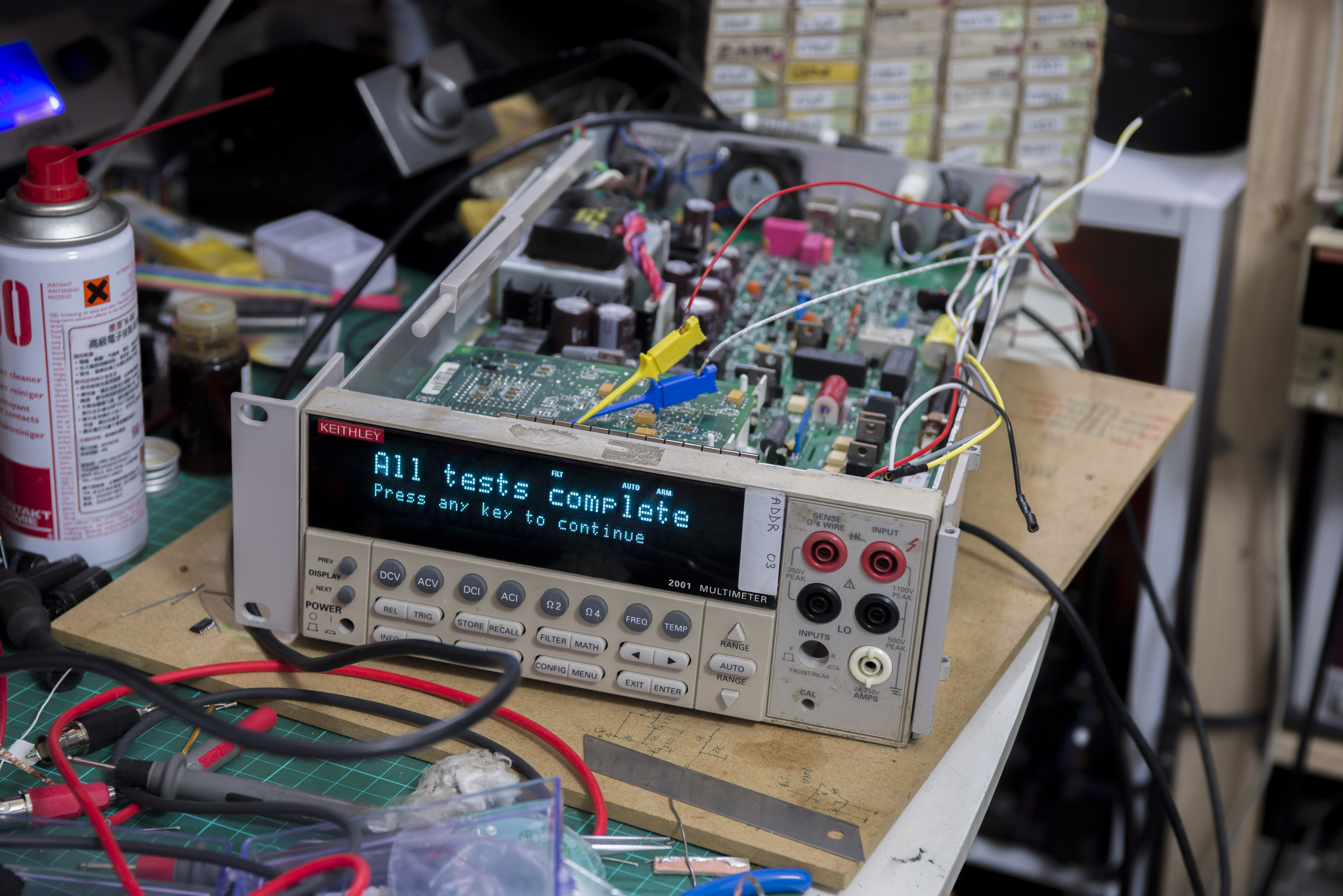
No erros detected, very well. If there are errors, meter showing ““ symbol after phrase *All tests complete.
I had selftest running in loops for an hour, no issues were detected.
Unit 2 Calibration
Calibration manual states next about user-level comprehensive calibration procedure:
The comprehensive calibration procedure calibrates DCV, DCI (except for the 2A range), 2-wire ohm, and 4-wire ohm functions.
At the end of the DC calibration procedure, AC self-calibration is performed to complete the calibration process.
Also there is note that full low-level calibration would be required if unit is repaired:
If the unit has been repaired, you should perform the low-level calibration procedure explained in paragraph 2.10.
I did not have suitable sources for it, so for now skipped low level calibration. Most of it is for AC performance.
Comprehensive user-level calibration
Since we replaced lot of critical analog components, all functions require recalibration.
Let’s try run user-level comprehensive calibration first, to see if what can be calibrated at this level.
As performance check reference setup we will use next equipment:
| Instrument | Detail | Last calibration / manufactured | Calibration step | S/N |
| Keithley 2002 | 8½ DMM | 2008 | DCV, 2W-ohm, 4W-ohm, DCI, ACV, ACI | 1167961 |
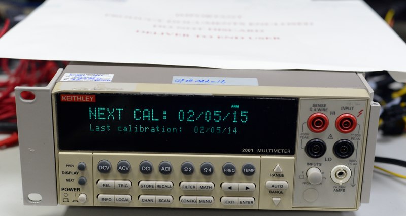
| Keithley 2001 | 7½ DMM | 05 February 2014, +24.3°C | DCV, 2W-ohm, 4W-ohm, DCI, ACV, ACI | 0544257 |
| Vishay VHP202Z | 1MEG 0.01% | Custom VPG 321217 VHA518-11 1ppm/°C 0.1W resistor | 2W-ohm | |
| Vishay VHP101 | 19K 0.005% | Custom VPG 321217 VHP101 matched/tracked 0.3ppm/°C | 2W-ohm, 4W-ohm | |
| Vishay VHP202Z | 10K 0.01% | Y607110K0000T9L high-stability precision resistor | 2W-ohm, 4W-ohm | |
| Vishay VHP101 | 1.9K 0.005% | Custom VPG 321217 VHP101 matched/tracked 0.3ppm/°C | 2W-ohm, 4W-ohm | |
| Vishay VHP101 | 95K 0.005% | Custom VPG 321217 VHP101 matched/tracked 0.3ppm/°C | 2W-ohm, 4W-ohm | |
| Vishay VHP202Z | 190R 0.005% | Y6071190R000V0L high-stability precision resistor | 2W-ohm, 4W-ohm | |
| Vishay VHP202Z | 19R 0.05% | Y607119R0000A0L high-stability precision resistor | 2W-ohm, 4W-ohm | |
| Vishay CSNG 3c | 2.5R resistor | Custom VPG 321215 CSNG 0.5ppm/°C, 9W, 1.6A | 2W-ohm, 4W-ohm | |
| xDevs.com KX | LTZ1000A REF | Ultra-zener high-stability voltage reference 7V | DCV | |
| xDevs.com KX | LTZ1000A REF | As above, divided to 1.9V | DCV | |
| HP 33120A | ARB | 20ppm ARB | ACV, Low-level AC cal | US34006542 |
| EDC MV106 | DC Voltage standard | Calibrated in February 2014 from K2001 | DCV up to 10V |
Custom VHP101 resistors are matched between within 0.01%, with 0.5 ppm/°C tracking tempco on best effort.
Custom resistors with VPG numbers were ordered with in-house PMO stabilization procedure. You don’t want to know a price for these :).
User-level calibration consist of these steps:
- Low-thermal short calibration step.
- +2V DC calibration step.
- +20V DC calibration step.
- 20kΩ calibration step.
- 1MΩ alibration step.
- Open circuit calibration step.
- Calculate DC cal constants.
Low-level calibration
Low level calibration have lot more steps, mainly for AC function, as well as DCI,ACI steps.
- 20V AC at 1kHz step.
- 20V AC at 30kHz step.
- 200V AC at 1kHz step.
- 200V AC at 30kHz
- 1.5V AC at 1kHz step.
- 0.2V AC at 1kHz step.
- 5mV AC at 100kHz step.
- 0.5mV AC at 1kHz step.
- +2V DC step.
- -2V DC step.
- 0V DC step.
- +20mA AC at 1kHz step.
- +0.2A DC step.
- +2A DC step.
- 2V AC at 1Hz step.
20V AC at 1kHz step setup
Ambient temperature: +24.0 °C
Here we use *20 bipolar amplifier to output 20 VAC sine wave at 1kHz. Source 1.000 VAC provided from HP 3245A, verified by HP 3458A.
Voltage level source is calibrated Keithley 2400 SMU.
Setup was allowed to stabilize thermally for 10 minutes before performing calibration step.
Details TBD..
20V AC at 30kHz step setup
Ambient temperature: +24.0 °C
Here we use *20 bipolar amplifier to output 20 VAC sine wave at 30kHz. Source 1.000 VAC provided from HP 3245A, verified by HP 3458A.
Voltage level source is calibrated Keithley 2400 SMU.
Setup was allowed to stabilize thermally for 10 minutes before performing calibration step.
Details TBD..
200V AC at 1kHz step setup
Ambient temperature: +24.0 °C
Here we use *20 bipolar amplifier to output 200 VAC sine wave at 1kHz. Source 10.000 VAC provided from 33120A, verified by calibrated Keithley 2001 DMM.
Voltage level source is calibrated Keithley 2400 SMU.
Setup was allowed to stabilize thermally for 10 minutes before performing calibration step.
Details TBD..
200V AC at 30kHz setup
Ambient temperature: +24.0 °C
Here we use *20 bipolar amplifier to output 200 VAC sine wave at 30kHz. Source 10.000 VAC provided from 33120A, verified by calibrated Keithley 2001 DMM.
Voltage level source is calibrated Keithley 2400 SMU.
Setup was allowed to stabilize thermally for 10 minutes before performing calibration step.
Details TBD..
1.5V AC at 1kHz step setup
Ambient temperature: +24.0 °C
Here we use output 1.5 VAC sinewave at 1kHz from HP 3245A, verified by HP 3458A.
Setup was allowed to stabilize thermally for 10 minutes before performing calibration step.
Details TBD..
0.2V AC at 1kHz step setup
Ambient temperature: +24.0 °C
Here we use output 0.2 VAC sinewave at 1kHz from HP 3245A, verified by HP 3458A.
Setup was allowed to stabilize thermally for 10 minutes before performing calibration step.
Details TBD..
5mV AC at 100kHz step setup
Ambient temperature: +24.0 °C
Here we use divided output 1.000 VAC sinewave at 100kHz to 5 mVAC voltage from HP 3245A, verified by HP 3458A.
Setup was allowed to stabilize thermally for 10 minutes before performing calibration step.
Details TBD..
0.5mV AC at 1kHz step setup
Ambient temperature: +24.0 °C
Here we use divided output 1.000 VAC sinewave at 1kHz to 0.5 mVAC voltage from HP 3245A, verified by HP 3458A.
Setup was allowed to stabilize thermally for 10 minutes before performing calibration step.
Details TBD..
+2V DC step setup
Ambient temperature: +24.0 °C
Here we use divided output 2.00000 VDC voltage from battery-powered KX reference (LTZ1000-based) connected to DMM in normal polarity.
Setup was allowed to stabilize thermally for 10 minutes before performing calibration step.
Details TBD..
-2V DC step setup
Ambient temperature: +24.0 °C
Here we use divided output 2.00000 VDC voltage from battery-powered KX reference (LTZ1000-based) connected to DMM in reverse polarity.
Setup was allowed to stabilize thermally for 10 minutes before performing calibration step.
Details TBD..
0V DC step setup
Ambient temperature: +24.0 °C
For this step input terminals were shorted with 4W-star short PCB.
Setup was allowed to stabilize thermally for 10 minutes before performing calibration step.
Details TBD..
+20mA AC at 1kHz step setup
For this step will use HP 3245A, verified by HP 3458A.
Details TBD..
+0.2A DC step setup
Ambient temperature: +24.0 °C
For this setup will use Keithley 2400 freshly calibrated to HP 3458A.
Current measured also with calibrated Keithley 2001. Setup was allowed to stabilize thermally for 30 minutes before performing calibration step.
Details TBD..
+2A DC step setup
Ambient temperature: +24.0 °C
For this setup will use 2000.000 mA current MOSFET source, with 2 x Vishay PG CSNG 2.5 ohm resistor (9W, 0.5ppm/°C, 1.6A rating).
Current measured with calibrated Keithley 2001. Current source circuit controlled from LTZ1000A reference VREF fixed voltage output.
Trim for current level was performed after reaching system thermal equilibrium.
Setup was allowed to stabilize thermally for 30 minutes before performing calibration step.
Details TBD..
2V AC at 1Hz step setup
HP 3245A, verified by HP 3458A. Output voltage also measured by calibrated Keithley 2001.
Unit #7 repair


This section is still work in progress, sorry.
Same issue with bad old capacitors:

Don’t wait for your capacitors become this old, replace them each 5-7 years even if they look OK from outside.
New capacitors (Chemicon) ready to install:
Let’s take a look on analog board parts in this unit:

Voltage reference is old aged LM399, OHM current source resistors are Vishay foil unlike other unit which had PTF56 resistors.


Digital board


Unit #7 calibration section
Infrared thermal images
Here are thermal images of two units, K0 (faulty) and K1 (good) for comparison. All images were done using Fluke Ti32 imager.

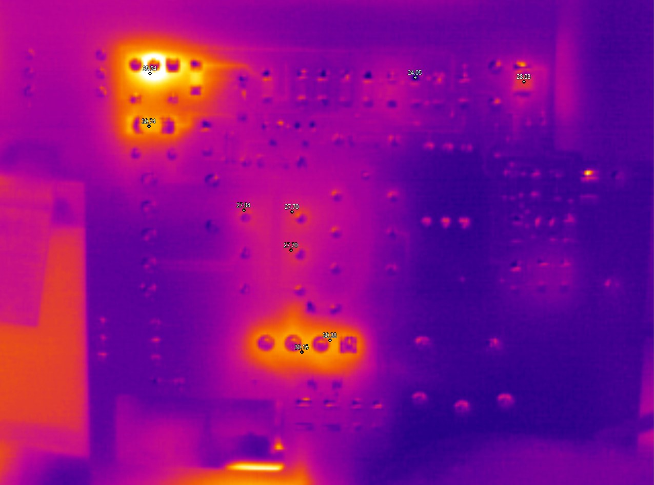
Image 1: Back analog PCB, both shots faulty unit
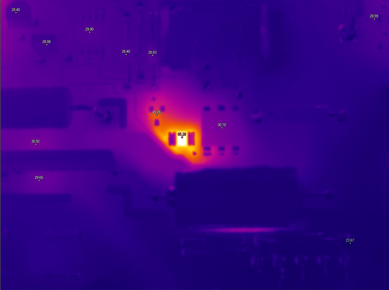
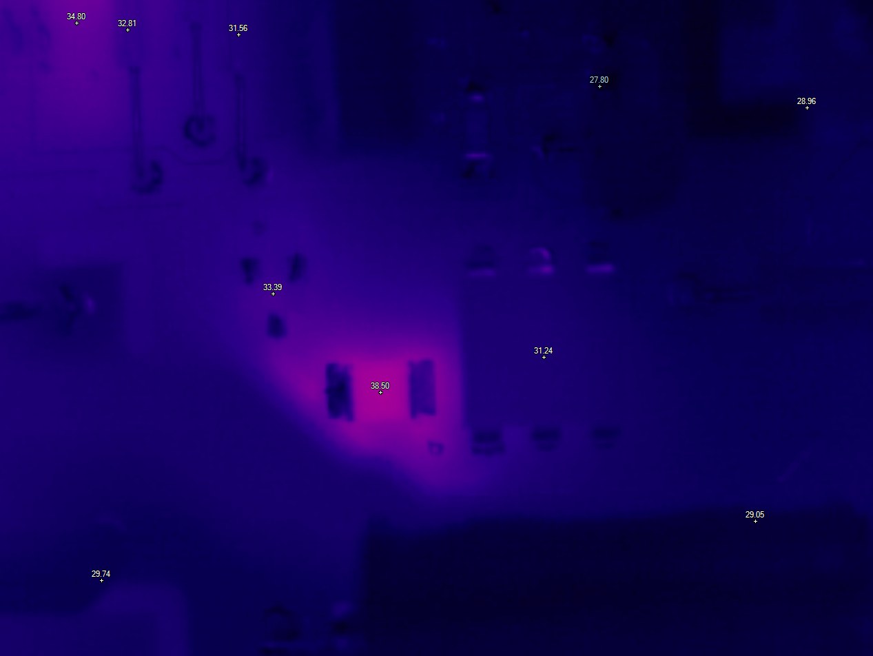
Image 1: R286 comparison, left is faulty unit, right is good unit
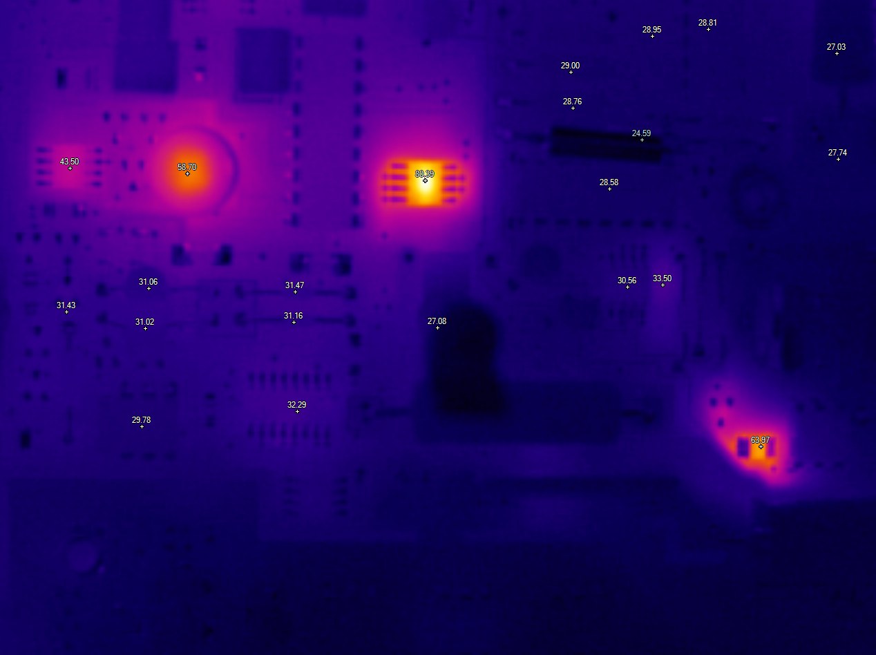

Image 1: Top w/o ADC module, left is faulty unit, right is good unit
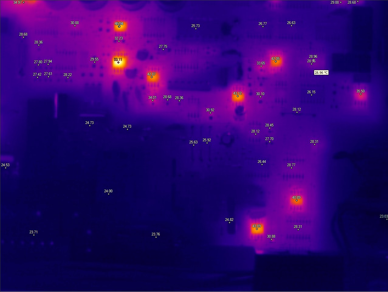
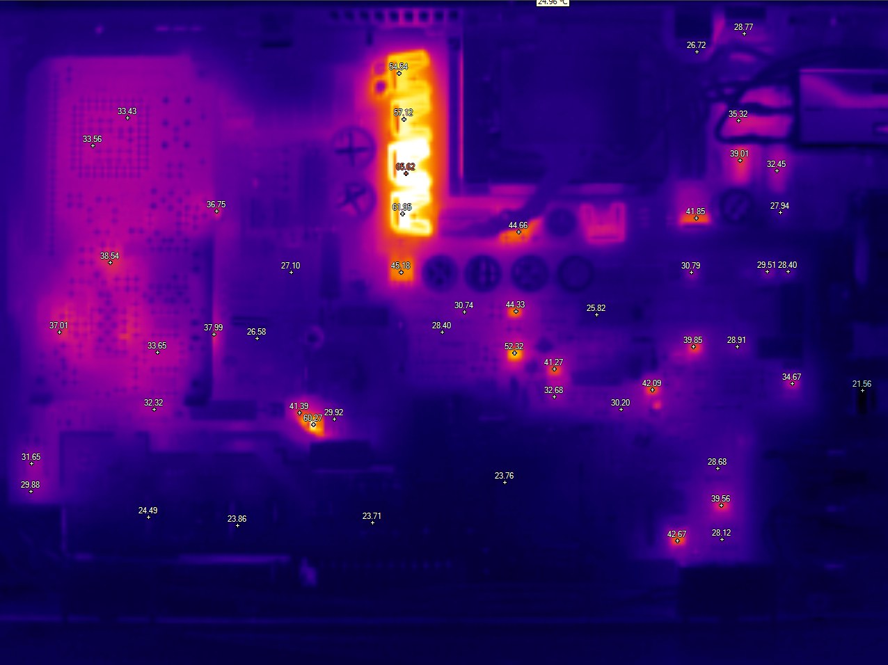
Image 1: Top images, both faulty unit
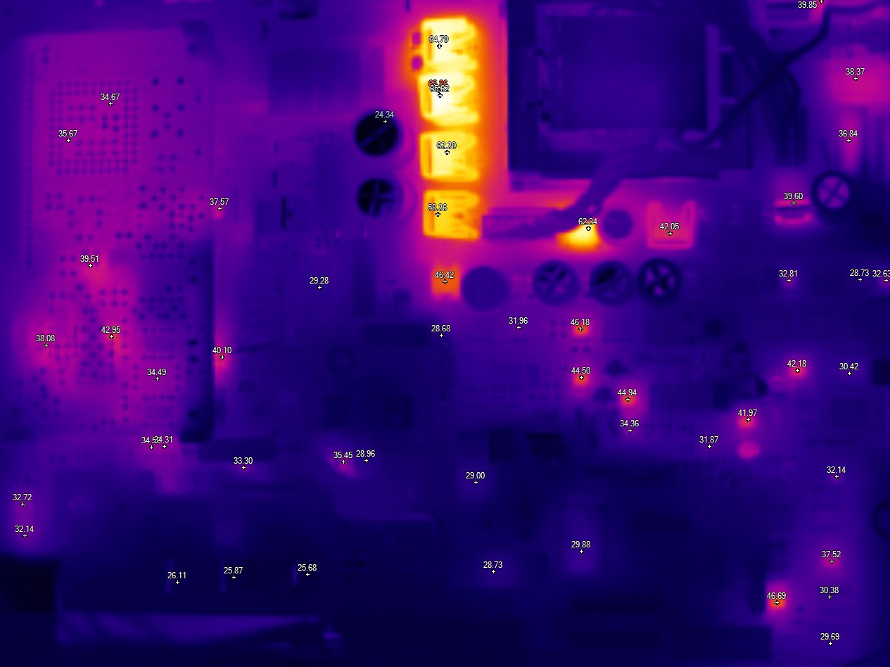

Image 1: Top images, both good unit
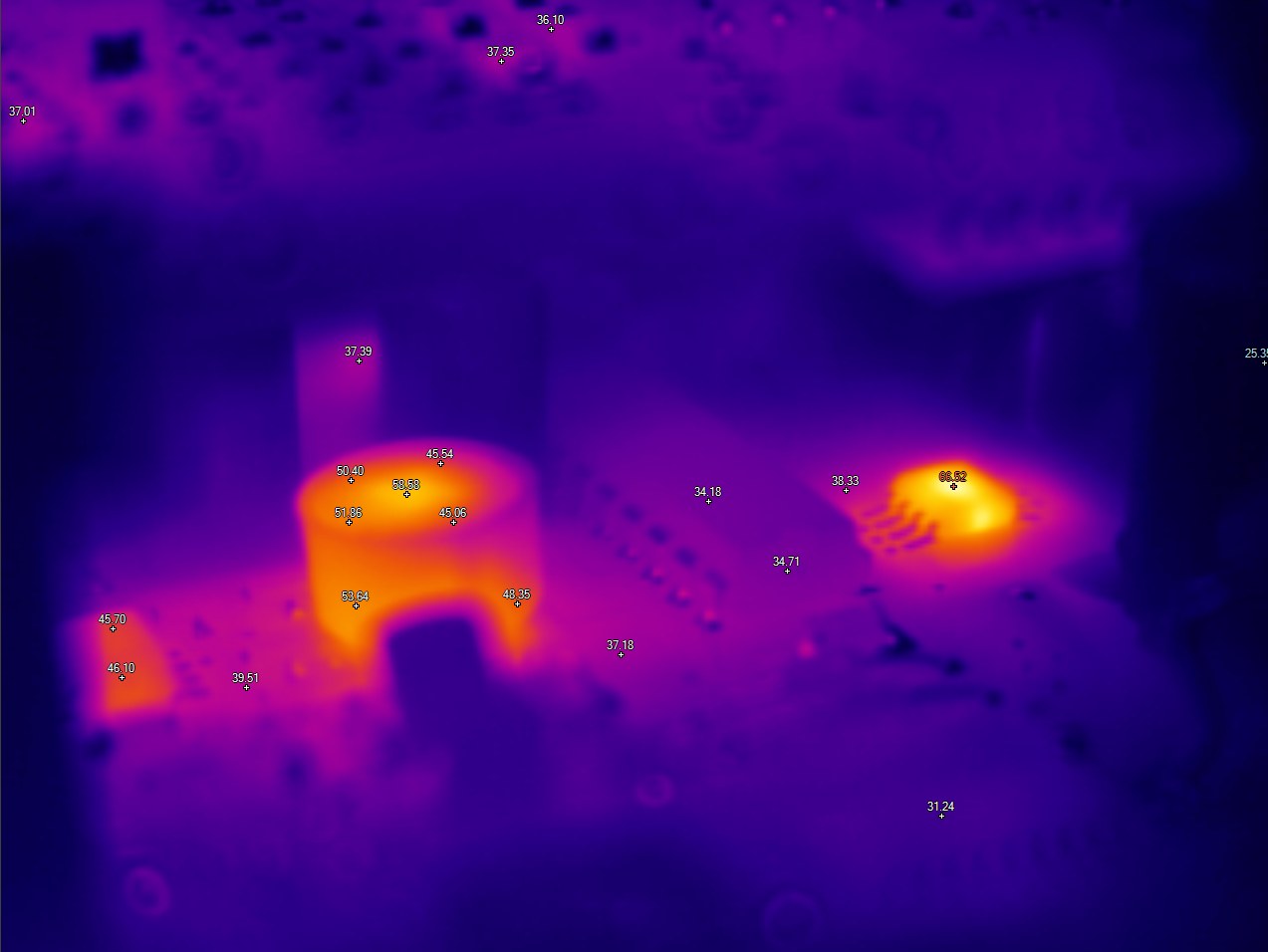
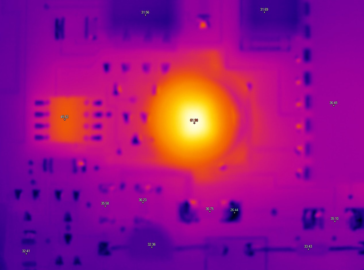
Image 1: LM399 voltage reference circuitry, left – bad unit, right – good


Image 1: VREF on bad unit, rear side of ADC module
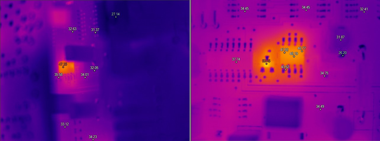
Image 1: U324 area, faulty at left, good at right side
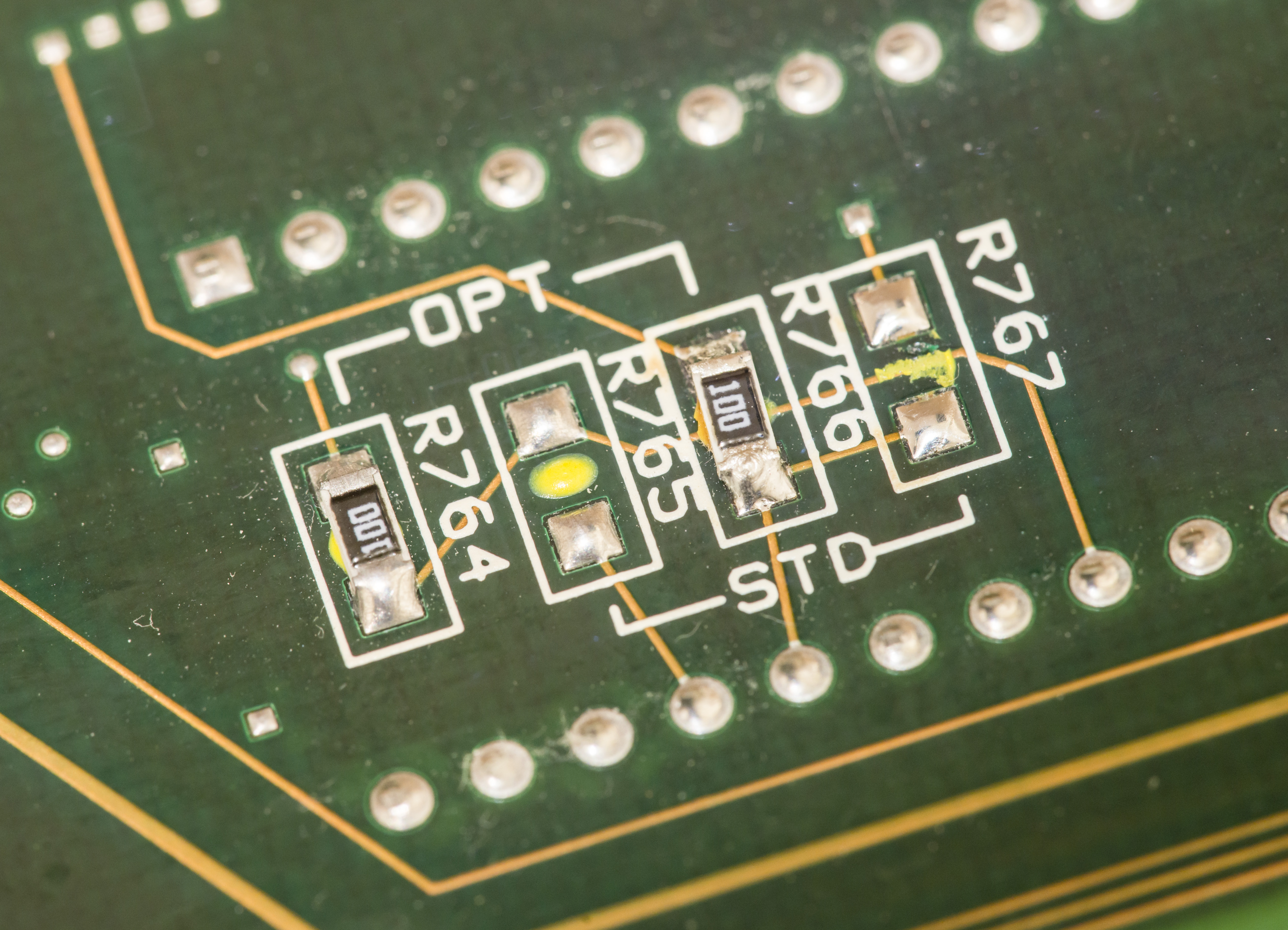
Memory options
Since we likely fixed unit, worth maximize it’s features as well, by installing option MEM2 on digital board.
This is rather simple operation, already covered before in this article so will not put too much details in here.

| Option | Hardware | Storage memory size | Setup profiles |
| STD | SRAM IC | xxx | only one, #0 |
| MEM1 | DS1230AB | xxxx or xxxxx w/o timestamps | up to 5, #0 to #4 |
| MEM2 | DS1245Y | xxxx or xxxxx w/o timestamps | up to 10, #0 to #9 |
Memory option require to have DS12xx programmed to valid contents, which at least have matching serial number to one in calibration EEPROM.
Otherwise storage function will not work correctly (reset contents on power off, don’t allow extra setup profiles to be saved).
Performance verification
Testing such high-performance and resolution meter require even higher performance standards and calibration sources, such as Fluke 5700A, which are usually available only metrology labs.Keithley recommends next gear to check meter specifications:
| Function | Reference standard |
| DCV | Fluke 5700A |
During writing of this article there is no access to such equipment, so this simplified performance check without calibrator source/standards is not as accurate as it should be. I used next test gear to test my meters:
| Function | |
| DCV 200mV | xDevs.com KX LTZ1000 reference output divided |
| DCV 2V | xDevs.com KX LTZ1000 reference output divided |
| DCV 20V | xDevs.com KX LTZ1000 reference output direct and 20V ratio |
| DCV 200V | Keithley 2400 calibrated in January 2014 by Tektronix |
| DCV 1000V | 210V, Keithley 2400 calibrated in January 2014 by Tektronix |
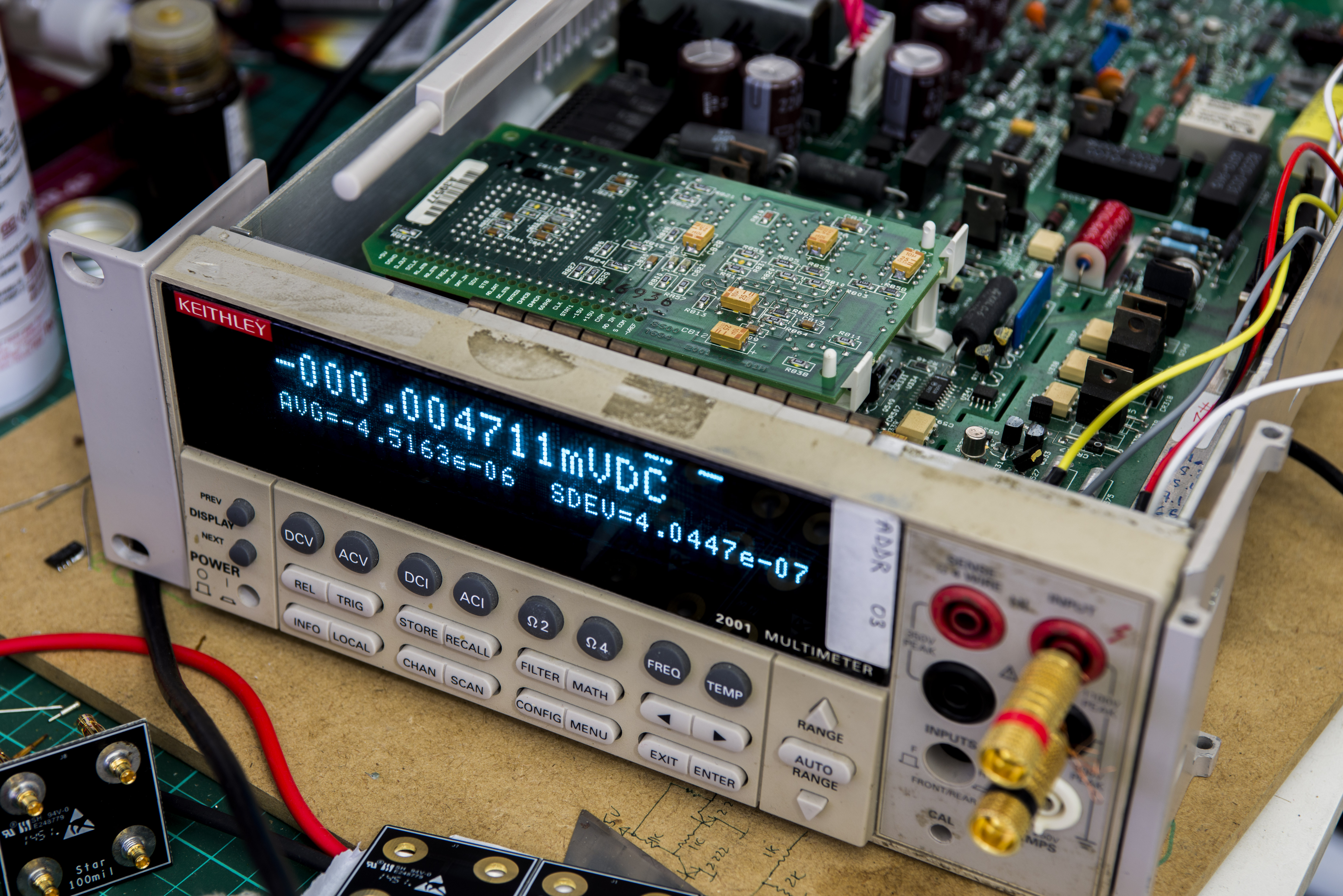
DCV Noise evaluation at shorted inputs
K2001 and many other DMMs were tested and compared in regards of zero voltage noise (short input) to get idea of overall measurement path noise. Methodology and test results are covered in detailed article here
Here’s some comparison data with Keithley 2001 & 2002’s, together with 3458A.
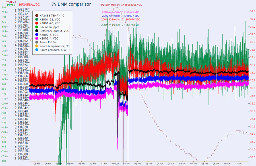
Setup:
- No filters on Keithley meters.
3458A – NPLC 100, AZER ON
Keithley’s – NPLC 10, AZER SYNC, no filter
Number after dash is just GPIB address.
All meters measure same KX LTZ1000 reference, direct 7V output, which is verified to have noise <0.2ppm. Stuff in the middle of the graph – just me, messing with other gear nearby, causing jumps due to knocking on cables and such.
| Noise measurement result | Voltage, µV | Deviation ppm/range |
|---|---|---|
| VDC 3458A | <1.2 peak-peak | ~0.12 ppm/10V |
| VDC 2002-4 | <2.5 peak-peak | ~0.125 ppm/20V |
| VDC 2002-6 | <2.5 peak-peak | ~0.125 ppm/20V |
| VDC 2001-20 | <15 peak-peak | ~0.75 ppm/20V |
| VDC 2001-21 | <22 peak-peak | ~1.1 ppm/20V |
Conclusion
Hope this helps to restore and fix your Keithley Model 2001. Many of repair process steps can be also applied to even more precious Model 2002 8½-digit multimeters, like was demonstrated in this article. These instruments are worth spending time with and once repaired and cared are able to deliver great performance and joy to any electronics engineering lab.
Discussion is very welcome via comment section or at our own IRC chat server: irc.xdevs.com (port 4808, channel: #xDevs.com) or at our very own xDevs forum. If you have information and performance reports of Keithley 2001 DMMs not mentioned or listed in this article, feel free to provide them and we will add them with next article update.
Projects like this are born from passion and a desire to share how things work. Education is the foundation of a healthy society - especially important in today's volatile world. xDevs began as a personal project notepad in Kherson, Ukraine back in 2008 and has grown with support of passionate readers just like you. There are no (and never will be) any ads, sponsors or shareholders behind xDevs.com, just a commitment to inspire and help learning. If you are in a position to help others like us, please consider supporting xDevs.com’s home-country Ukraine in its defense of freedom to speak, freedom to live in peace and freedom to choose their way. You can use official site to support Ukraine – United24 or Help99. Every cent counts.
Modified: June 2, 2026, 3:30 a.m.
References
- EEVBlog forum : K1801 nanovolt preamp thread
- EEVBlog : Restoration glory of Keithley 2001 DMM
- Documentation and firmwares
- Keithley document repro site
- Secret menu settings in Keithley gear
- Memory options on Keithley 2001/2002 series DMMs
- Video : Keithley 2001 secret menu demo
- xDevs.com : Nanovolt preamp EM A10 review
- Github: DS1245Y mod for FRAM replacement