Contents
- Intro
- Disclaimer
- Manuals
- Unit controls and exterior
- Teardown and construction
- Repair
- Calibration procedure
- Performance test
- Tweaks
- Conclusion
Intro
Sometimes even high-end 8½-digit DMM is not a best tool, since these meters still have limited input resistance and leakage current to earth. Sometimes it’s a deal breaker, and small nV-meter with battery power only would be a better use in differential bridge measurements. This is particularly useful for high-voltage high-resistance bridges and such.
For this and few other reasons, we got Fluke Model 845AB null-meter for $250 USD. Let’s see what makes it work.
Electrical Specifications for Model 845
| Description | Manufacturer specification |
|---|---|
| Input Voltage Range | 1 microvolt to 1000 volt DC end scale in 19 ranges, using X1 and X3 progression |
| Input Resistance | 100 MΩ on 300 mV range and above, 10 MΩ on 100 mV range and above |
| Accuracy | ±2% end scale + 0.1 microvolt |
| Input Isolation | Better than 1012 Ω |
| DC CMRR | Better than 160 db |
| AC CMRR | 100 volts RMS or 120 db greater than end scale, whichever is less |
| AC Normal Mode Rejection (60Hz+) | AC voltages 60 db above end scale will effect reading <2% of end scale |
| Recorder Output | 0-1 volt, one side at chassis ground; to 0.5% of end scale. Output can be operated as a DC amplifier with a <=gain of 120 db |
| Stability of Zero | Better than 0.15 microvolt/hour, Better than 0.3 microvolt/day |
| Temperature Coefficient of Zero | Less than 0.1 microvolt/degree C from 15 °C to 35 °C |
| Zero Control Range | ±5 microvolt minimum |
| Overload Protection | Up to 1100 volts dc may be applied on any range. Typical recovery time is 4s |
| Input Power | Rechargeable battery or 115/230 VAC +/- 10%, 50 to 440 Hz |
| Battery life | 40 hours operation on full charge, trickle charge on line power |
| Weight | 10 pounds |
| Size | 8 inches high by 8 inches wide by 9 inches deep |
Fluke 845AB were sold new for $2500 USD during their lifetime and were considered a Primary Standards Laboratory-grade electronic instruments. Fluke 845AR was also used by industry as part of other instrumentation, such as resistance bridge measurement system and DC voltage standards.
Disclaimer
Redistribution and use of this article or any images or files referenced in it, in source and binary forms, with or without modification, are permitted provided that the following conditions are met:
- Redistributions of article must retain the above copyright notice, this list of conditions, link to this page (/fix/f845ab/) and the following disclaimer.
- Redistributions of files in binary form must reproduce the above copyright notice, this list of conditions, link to this page (/fix/f845ab/), and the following disclaimer in the documentation and/or other materials provided with the distribution, for example Readme file.
All information posted here is hosted just for education purposes and provided AS IS. In no event shall the author, xDevs.com site, or any other 3rd party, including FLUKE be liable for any special, direct, indirect, or consequential damages or any damages whatsoever resulting from loss of use, data or profits, whether in an action of contract, negligence or other tortuous action, arising out of or in connection with the use or performance of information published here.
If you willing to contribute or add your experience regarding test instruments repairs or provide extra information, you can do so following these simple instructions
Manuals
Fluke 845A 845AB instruction manual (not complete), November 1967
Fluke 845A 845AB some pages from manual
Another copy of Fluke 845AB manual, complete with high-resolution schematics
LED modification from KO4BB site
Fluke 845AR instruction manual (rackmount version), April 1968
Fluke 845AR instruction manual
Credits for Glenn B. from EEVBlog forums for providing copy at 3rd document.
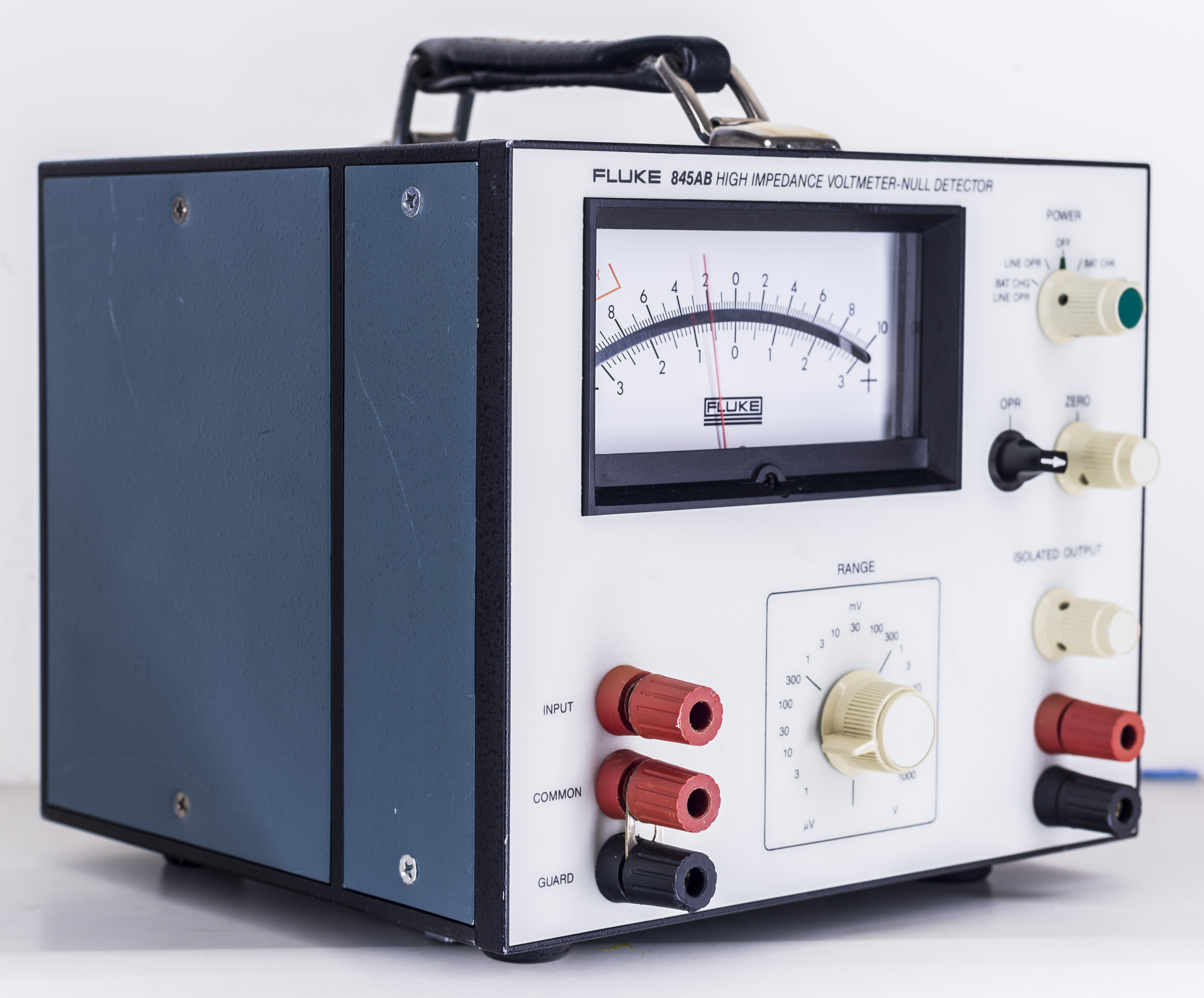
Unit controls and exterior
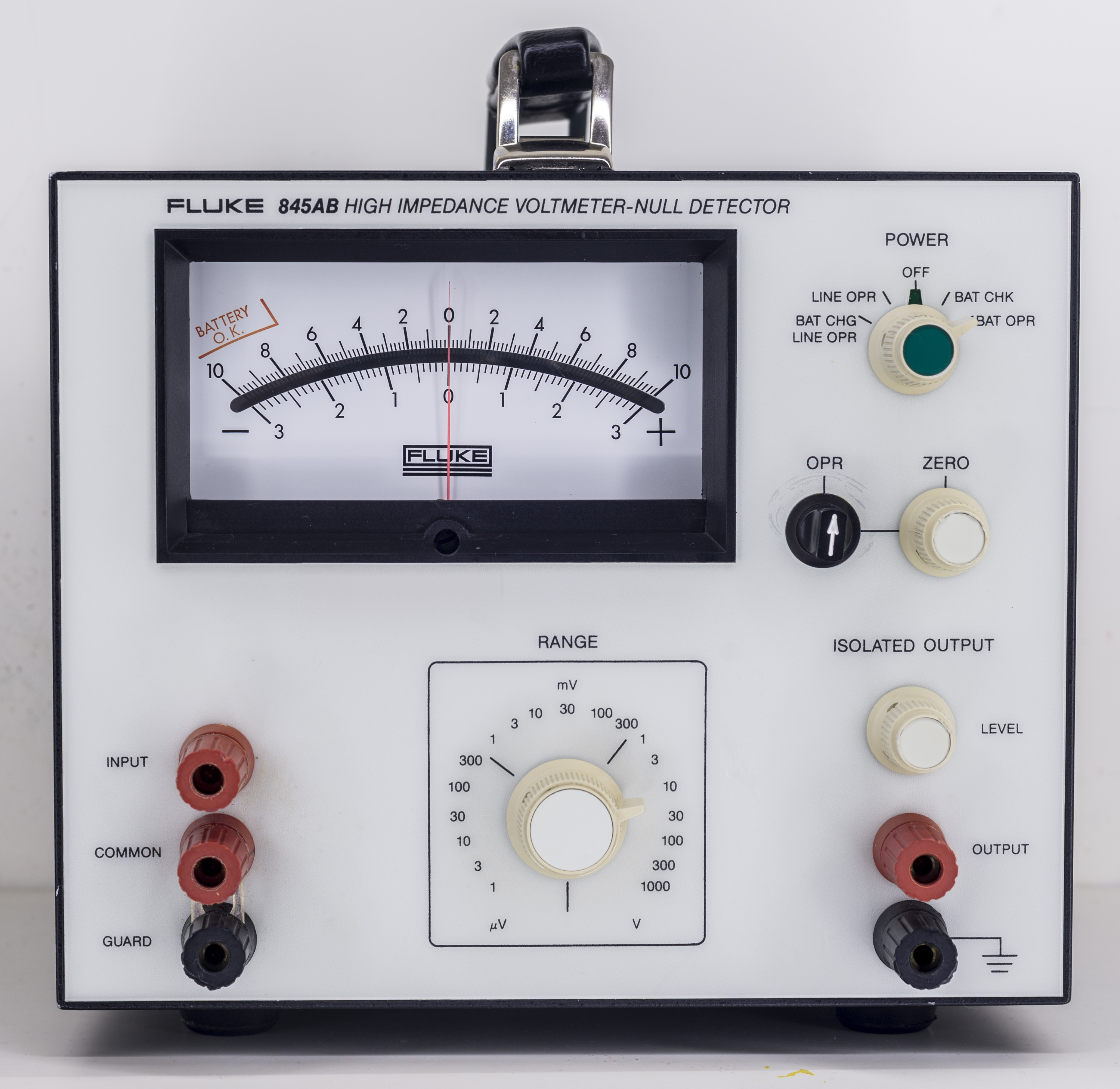
Meter’s front panel is very clean and easy to use. POWER switch have 5 positions:
- OFF – no comment required, everything turned off
- LINE OPR – operation from mains power
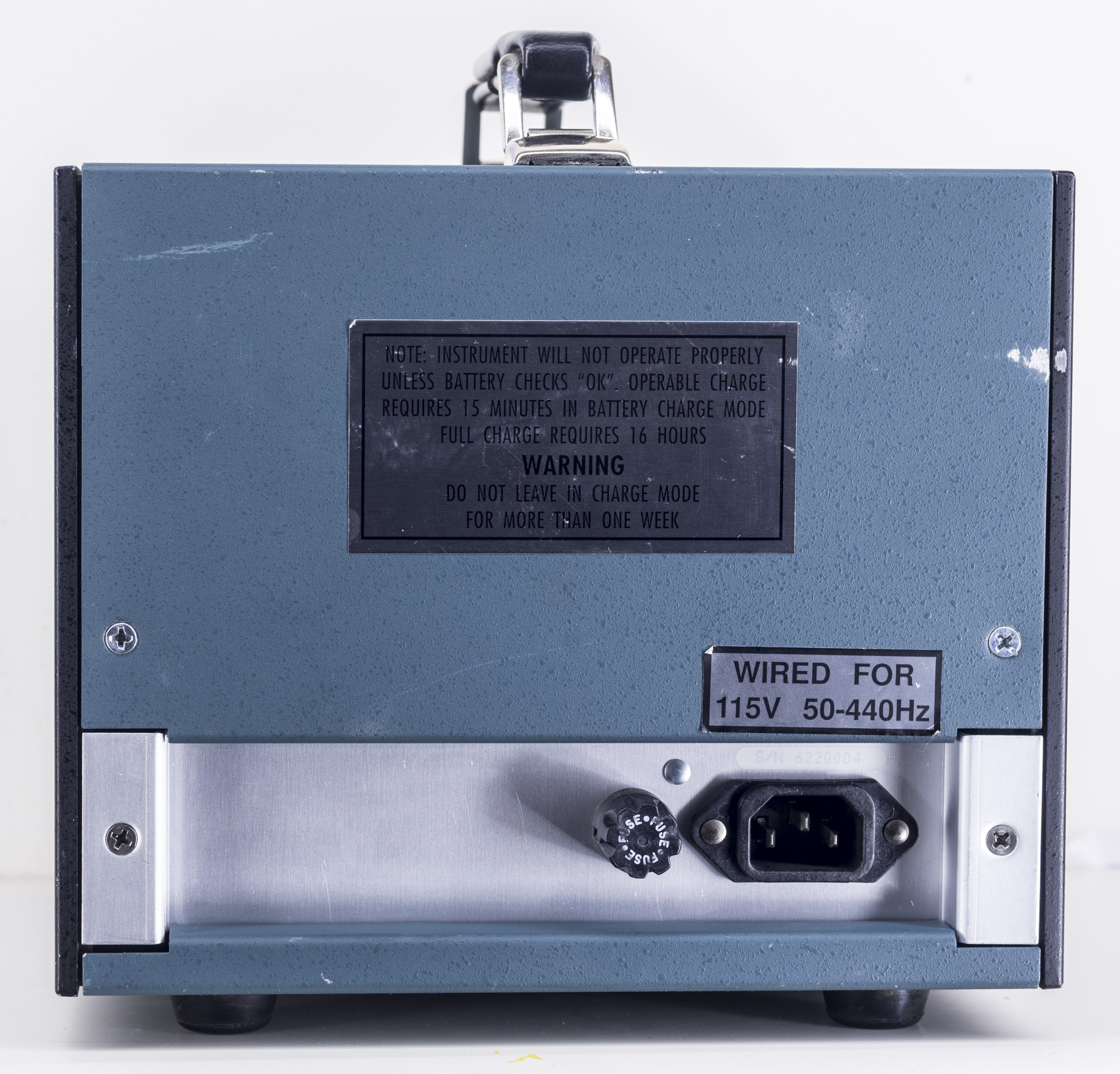
- BAT CHG/LINE OPR – operation from mains power and charging of internal battery. Full recharge time is 16 hours.
- BAT CHK – check battery voltage. Meter should deflect needle in “BATTERY O.K.” zone if battery is charged.
- BAT OPR – operation from battery power. Manual states at least 40 hours of continuous lifetime on single charge.
Black OPR rotary knob allow to select measurements from input terminal or from short to common to set zero by related ZERO rotary knob.
Isolated output provides interface to graphing meter or datalogger. Full scale is in range -1.0/1.0V, but it actually can go much higher than that.
Central rotary switch allow selection of input voltage range, from 1 µV to 1000 V, in total 19 ranges.
Input terminals are made from non-plated bare copper binding posts. Guard allow guarding to reduce leakage even further, to 1013 at best. There is no back-light for meter.
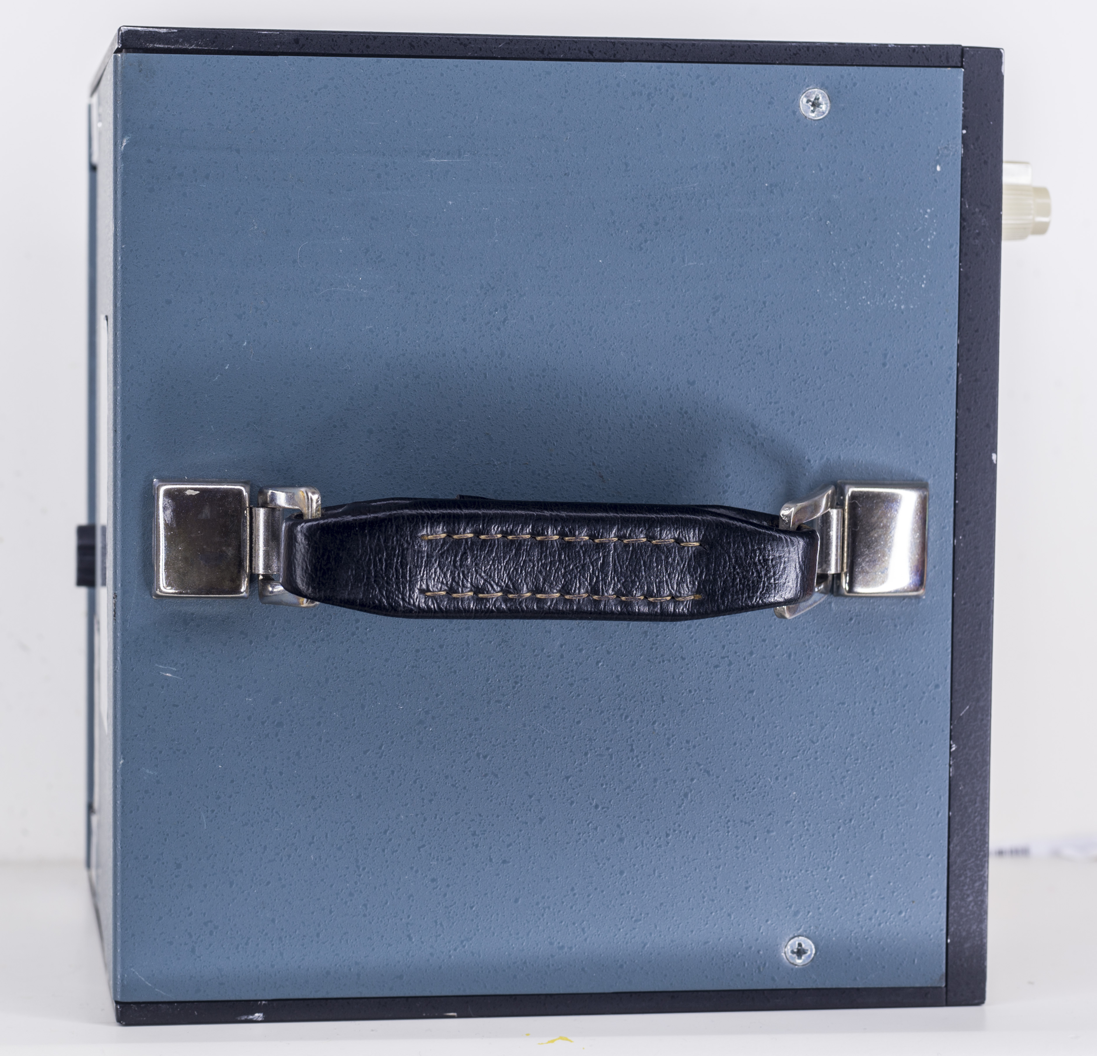
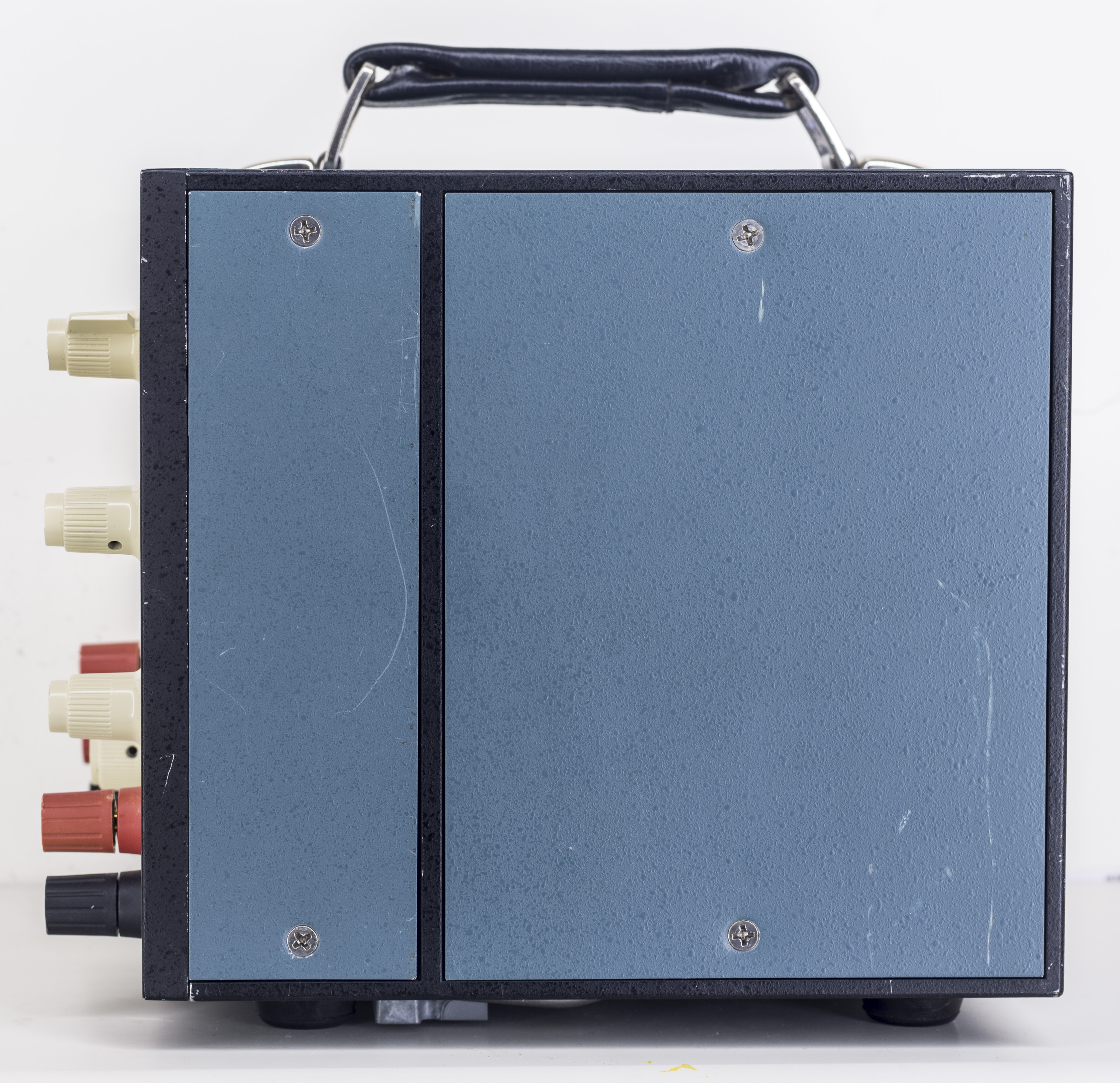
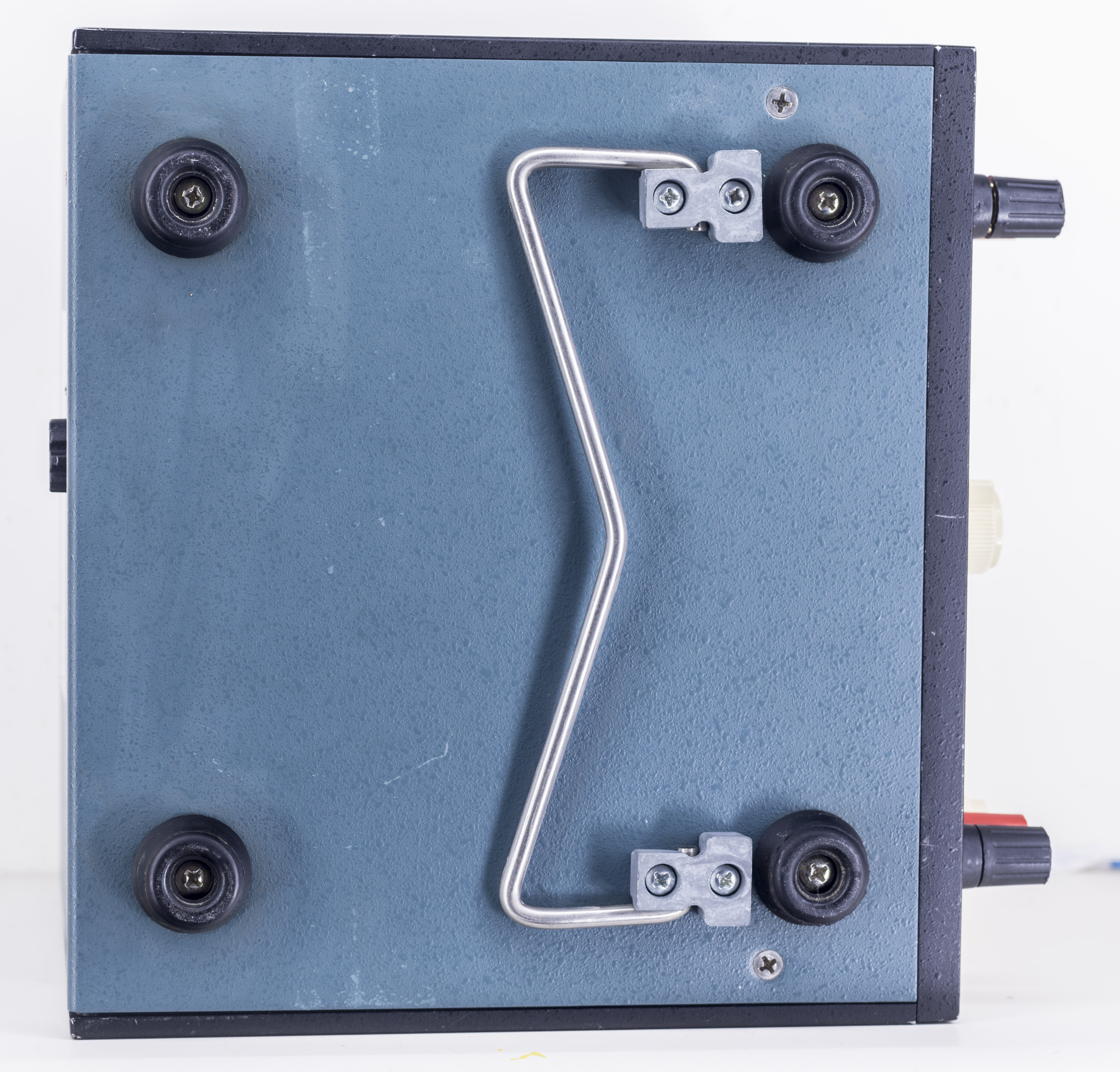
Overall chassis is well built and rather heavy-duty. The only plastic parts are knobs and meter frame. Rear panel have fuse holder and standard C14 IEC mains socket.
Tear-down and construction
Schematics combined from Fluke 845AR instruction manual is provided for your reference.
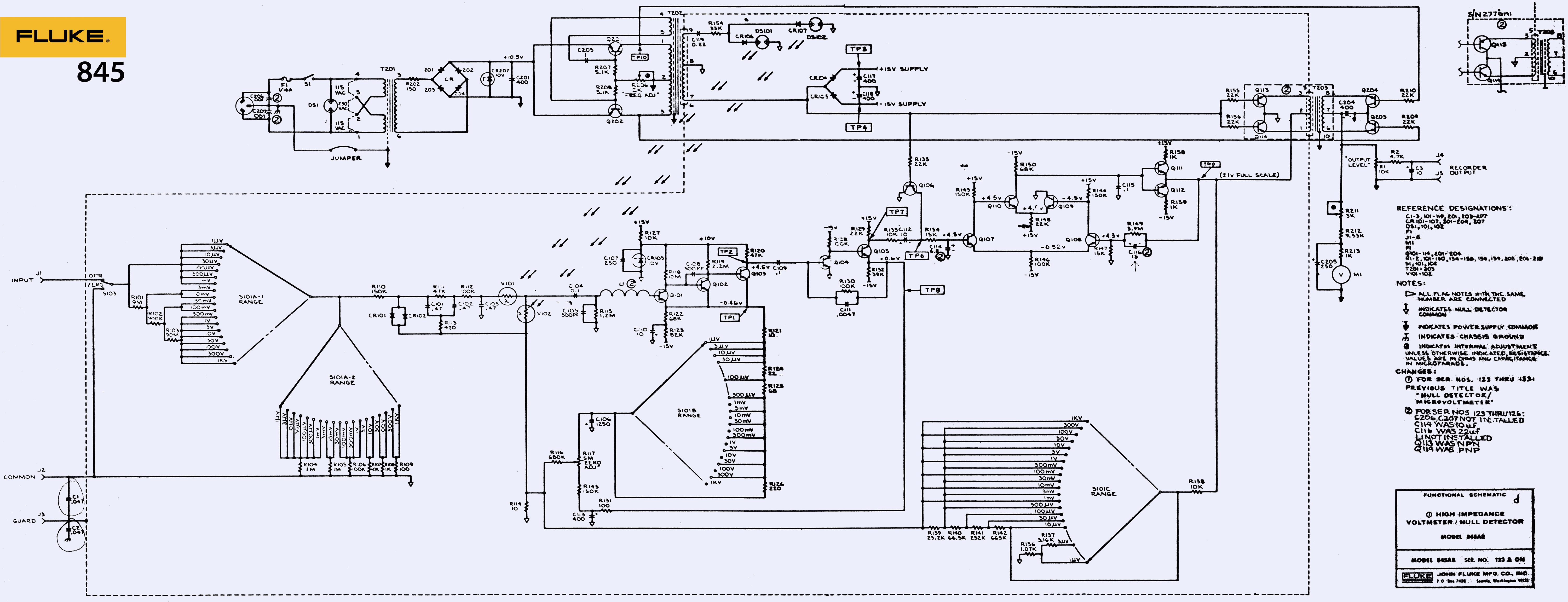
It’s rather simple concept, with just few parts in each block, with easy to understand operation, unlike most of modern test instrumentation gear filled with lots of digital logic, microcontrollers, firmware and so on.
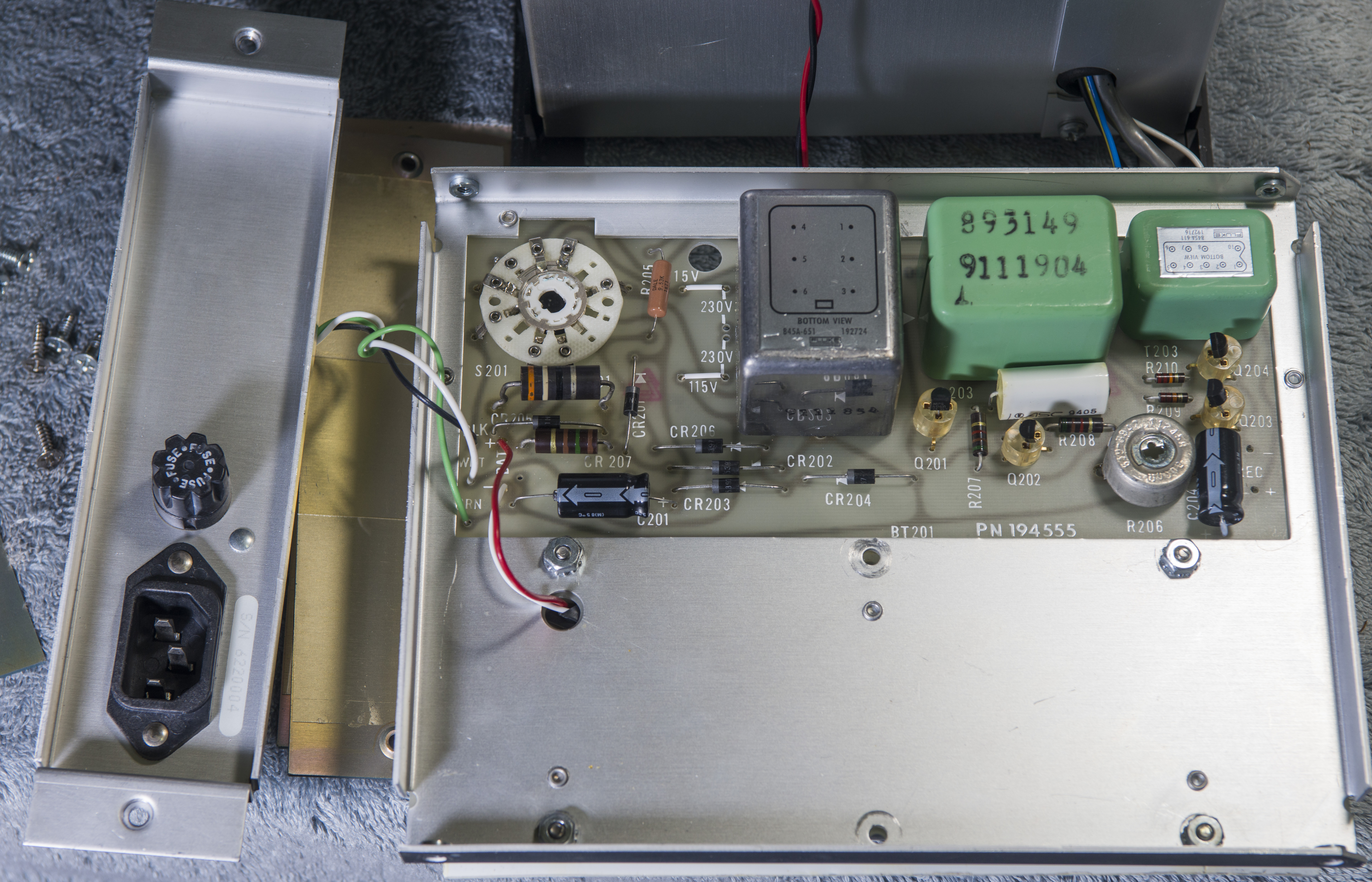
Metal panels are easy to remove, allowing easy access to inner circuitry. Only board accessible easily is the mains power/re-charge circuit with 84Hz multivibrator and transformers.
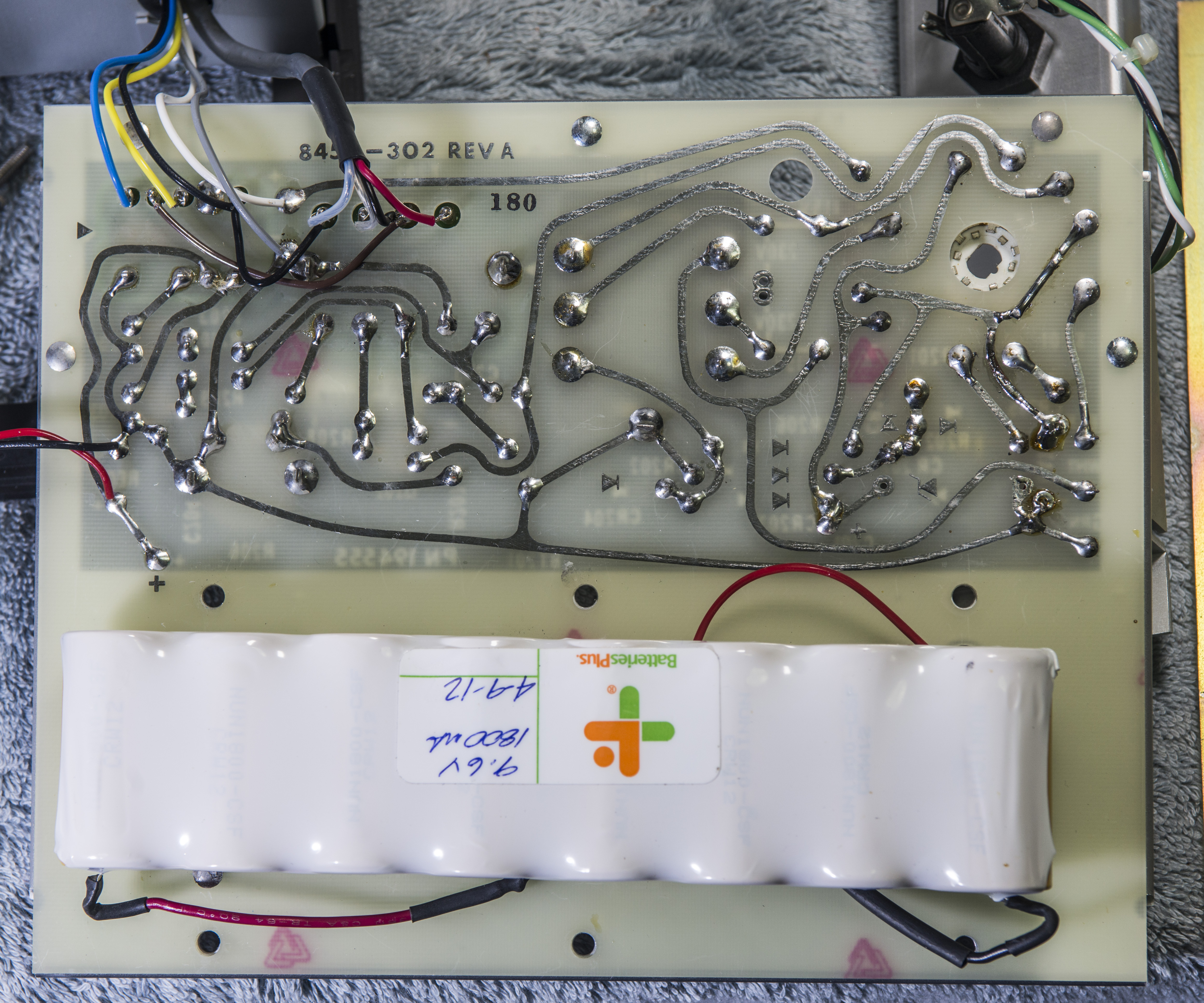
If one to trust label on battery pack, it’s rather fresh and unit was serviced before.
A sticker on battery says:
9.6V
1800mA
4-9-12
This probably means battery installation time, 4th September 2012. Measured battery voltage at +10.96 VDC, it’s OK.
Now, let’s remove aluminum covers or guarded section and see what’s inside.
Chopper amplifier
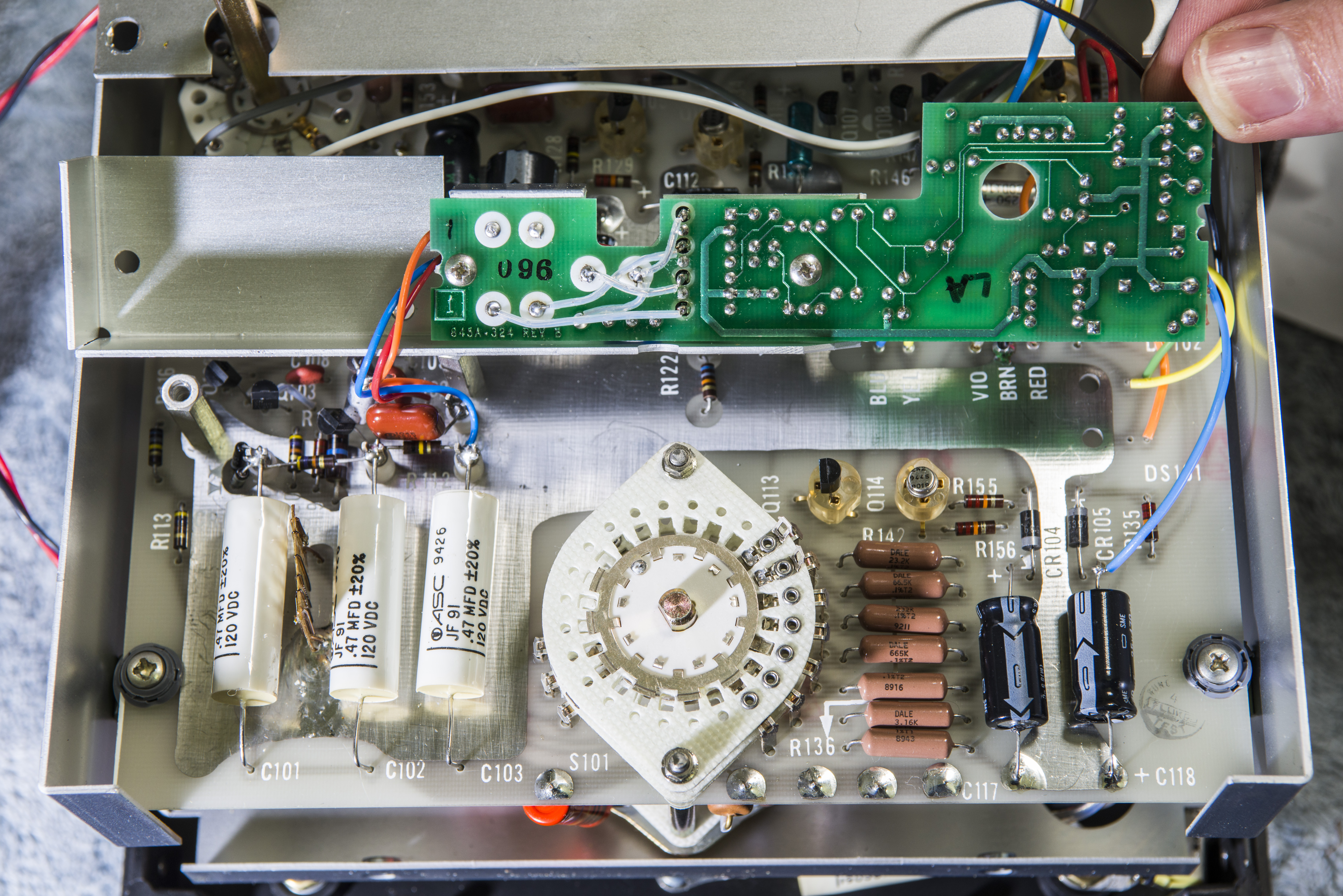
I was really expected to see infamous neon tubes, light guides and photo-resistor chopper amplifier, but was greeted instead with alien-looking green PCB with micropower regulator Linear LT1120CN8 and few HP 2731 optocouplers(?) !
LT1120 dated with 1993 week 52. Is it that optically-isolated Bilateral Analog chopper, which mentioned in Fluke 845AB manual’s note in 7/1993 print?
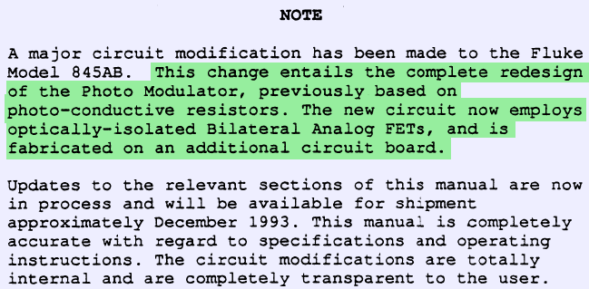
Indeed it is. I’ll be reverse engineering this circuit later on so we can know exactly what we dealing with here, and evaluate possibility of future improvements.
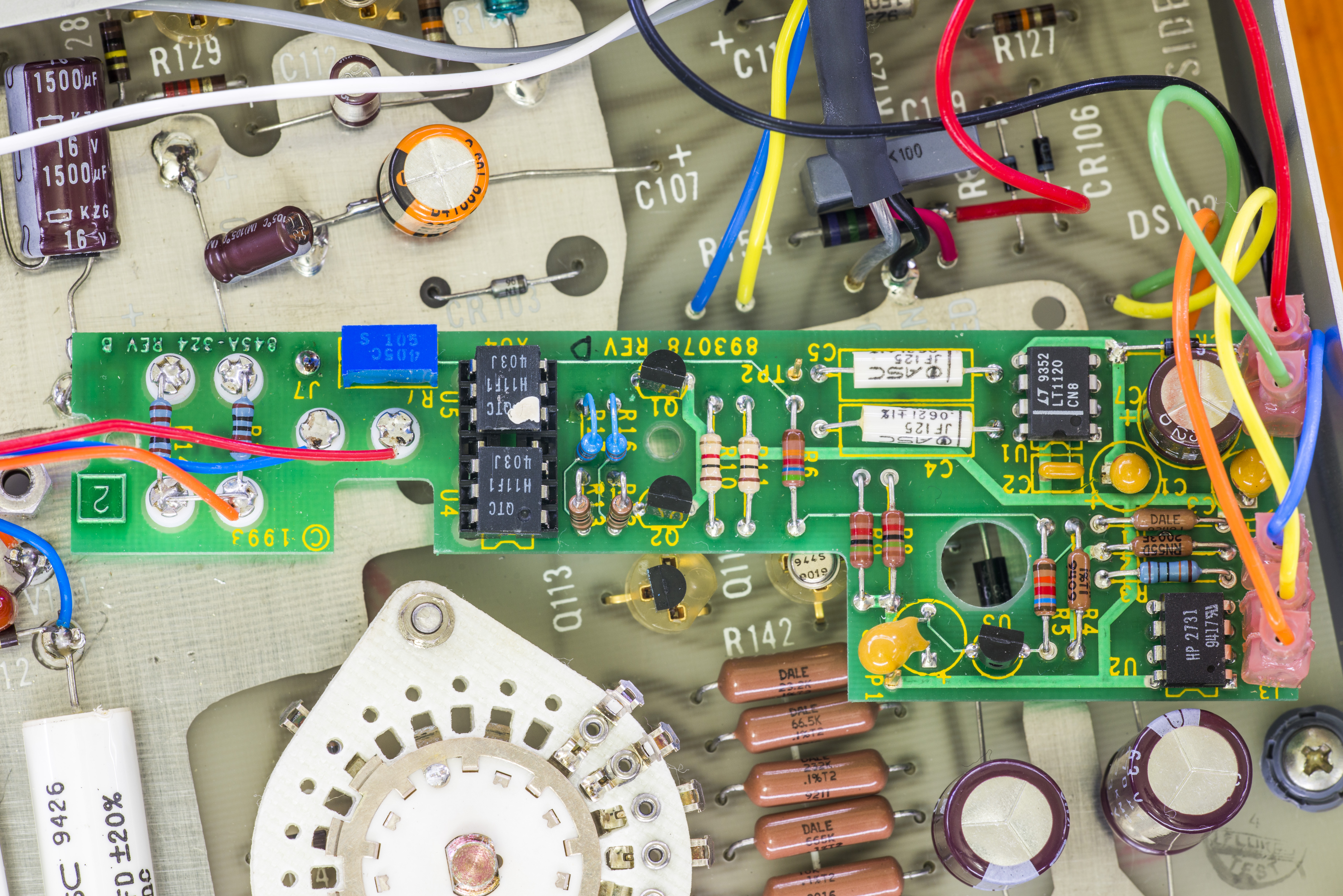
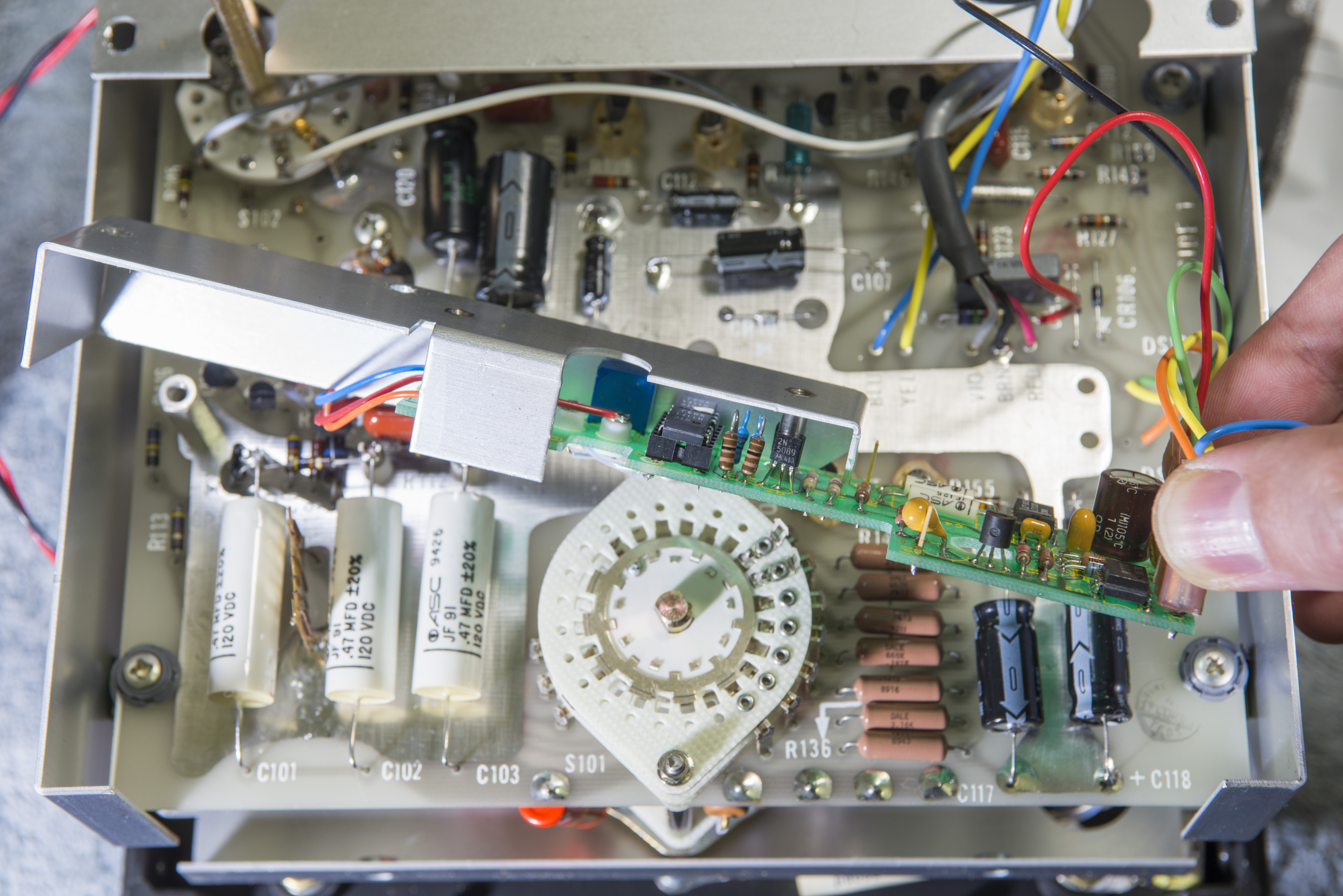
Here are some additional photos of chopper module board:
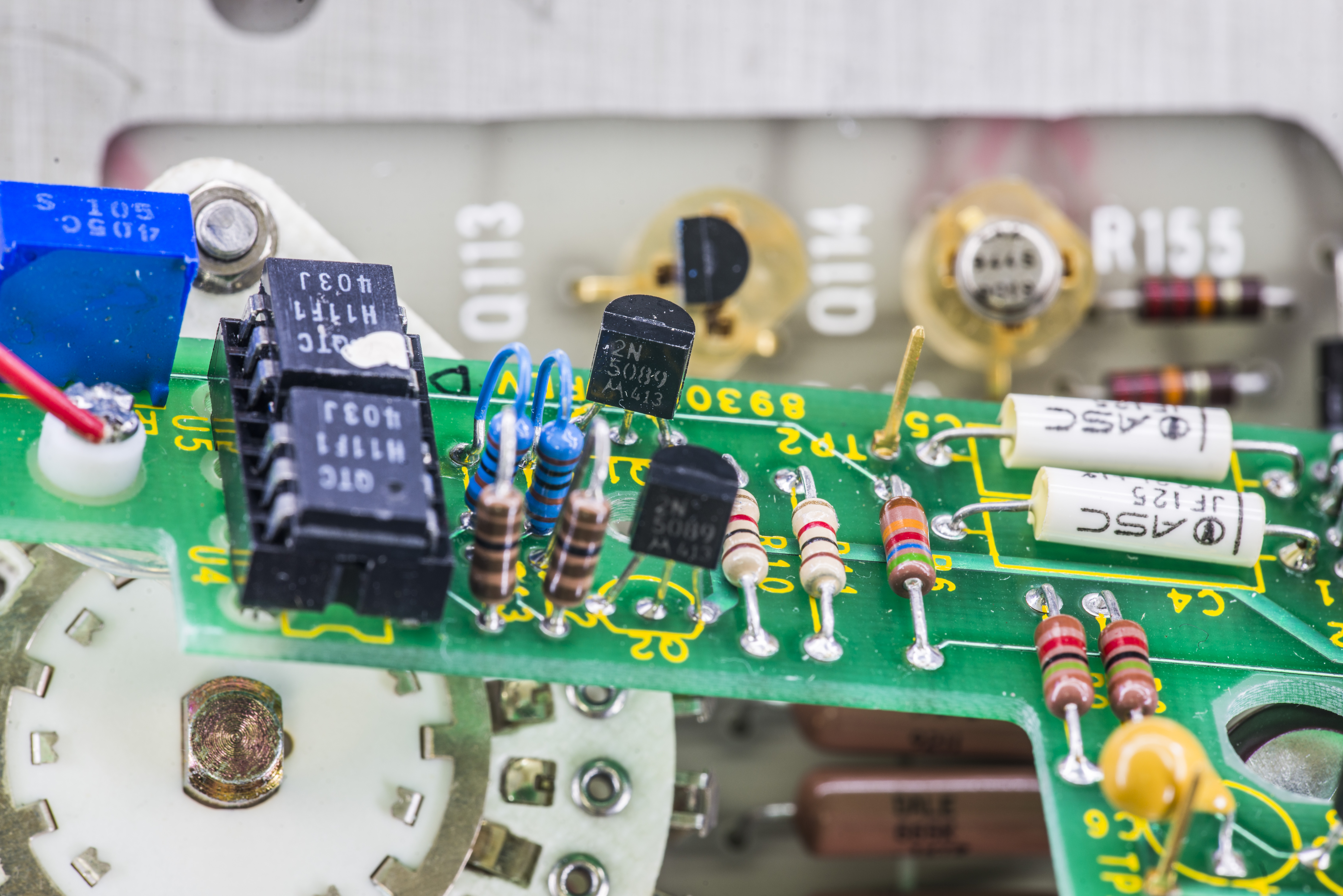
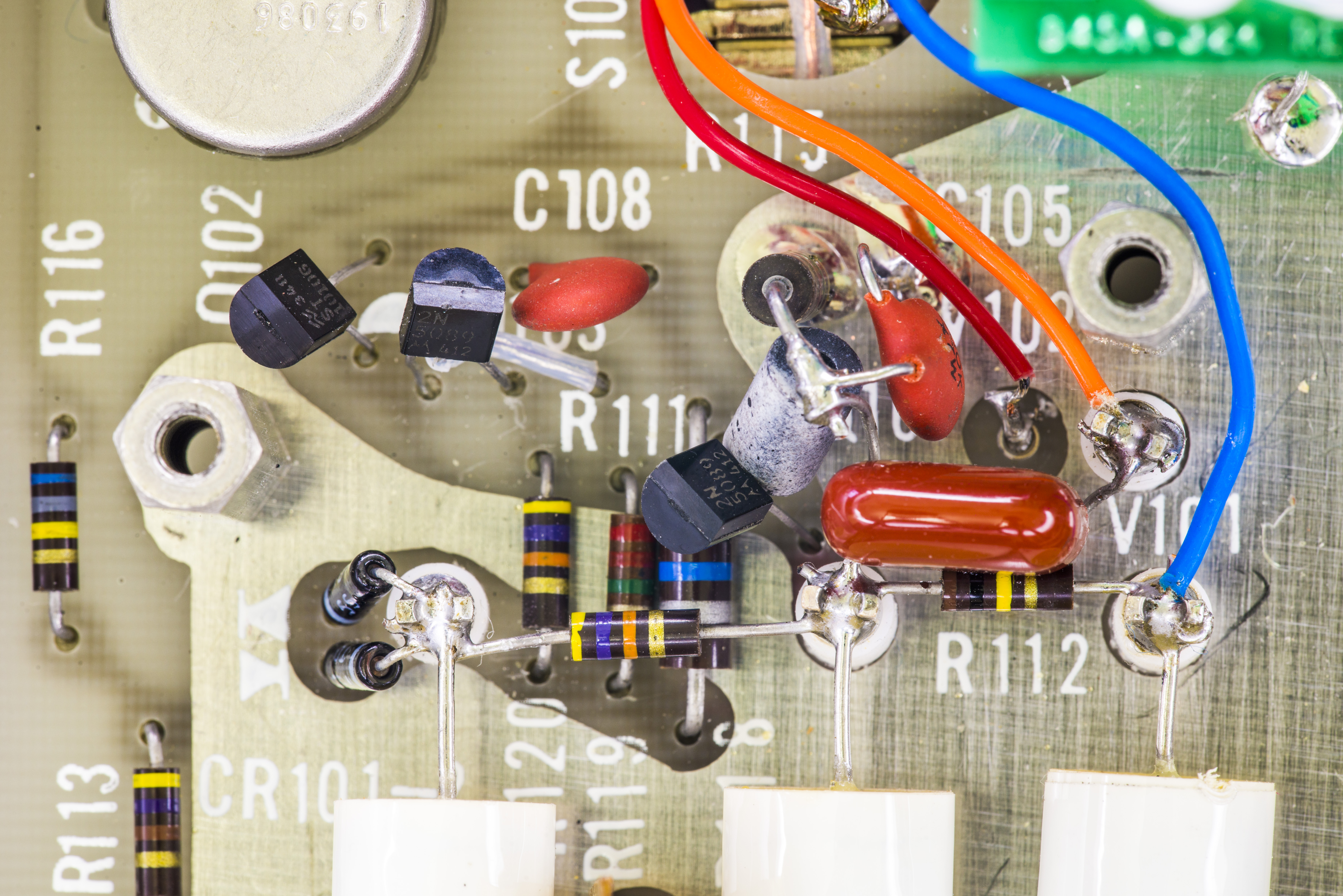
Transistors used are general purpose NPN’s 2N5089 in TO92 package with hFE about 400 and 30V maximum voltage.
Optocouplers are Fairchild H11F1, which are good FET switches with decent linearity and low offsets.


And connection of three wires from high impedance nodes on base board:
Repair
After initial inspection and testing next issues were spotted:
- Meter does not read anything in BAT OPR mode. It’s just dead on zero, like no power is supplied, even though BAT CHK shows good battery
- In LINE OPR mode meter is unable to zero on ranges below 30µV
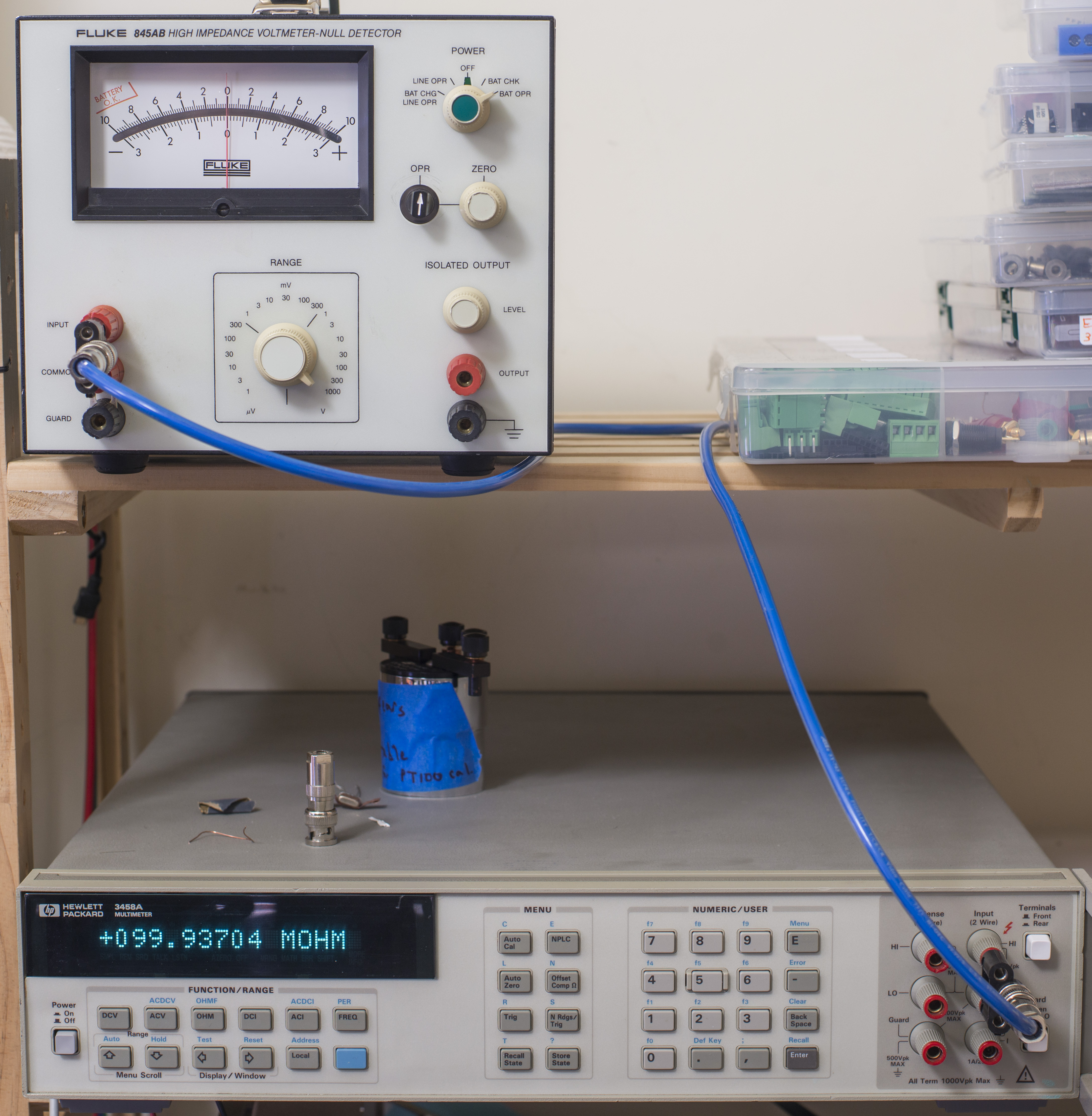
Rest of ranges seems to be working as expected. Input resistance measured by 3458A is 100 MΩ on high voltage ranges, 10 MΩ on mV ranges and ~250K&Omega on ranges below 1 mV.
Main supply voltage rails +15 and -15 were measured at 17.65 and -17.8 VDC respectively.
No operation in BAT OPR mode
First issue was resolved by fixing blown PCB track on Power supply P/C assembly, connecting battery positive terminal to S201C switch. This repair covered in YouTube video below.
Meter cannot zero on lowest ranges
Green PCB with chopper assembly has blue multi-turn trimmer pot, accessible from the side. This trimmer adjustment allowed shifting zero, and now meter can be zeroed on lowest 1 µV range.
This was an easy repair.
Replacement of all electrolytic caps
As usual with equipment with age over 10, replacement of all electrolytic capacitors should be a must-have maintenance procedure. This saves trouble of cleaning electrolyte leaks and further destruction. If you think that’s rare malfunction, be sure to check our Keithley Model 2001 experience with no less than 7 meters affected by damage from old capacitors.
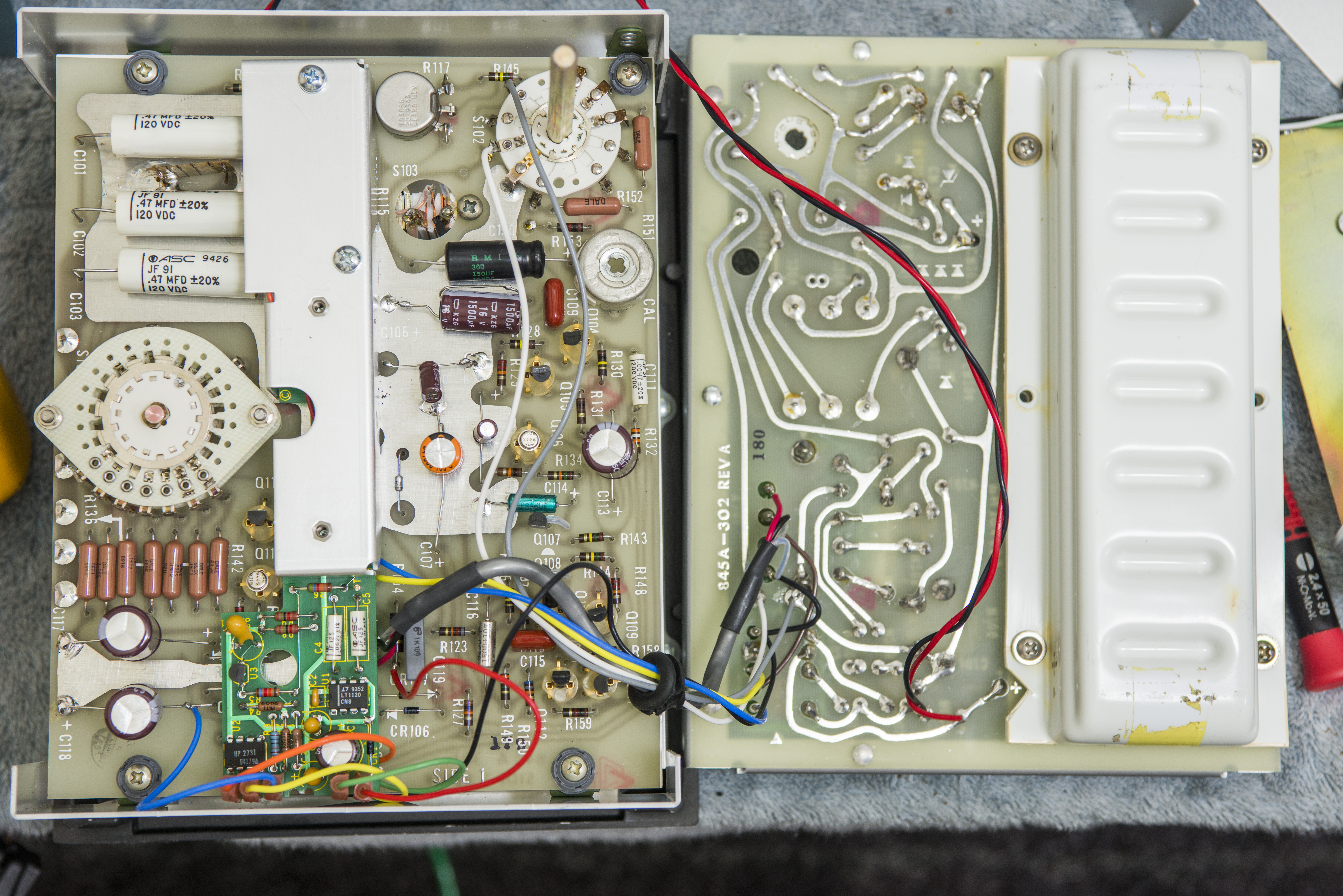
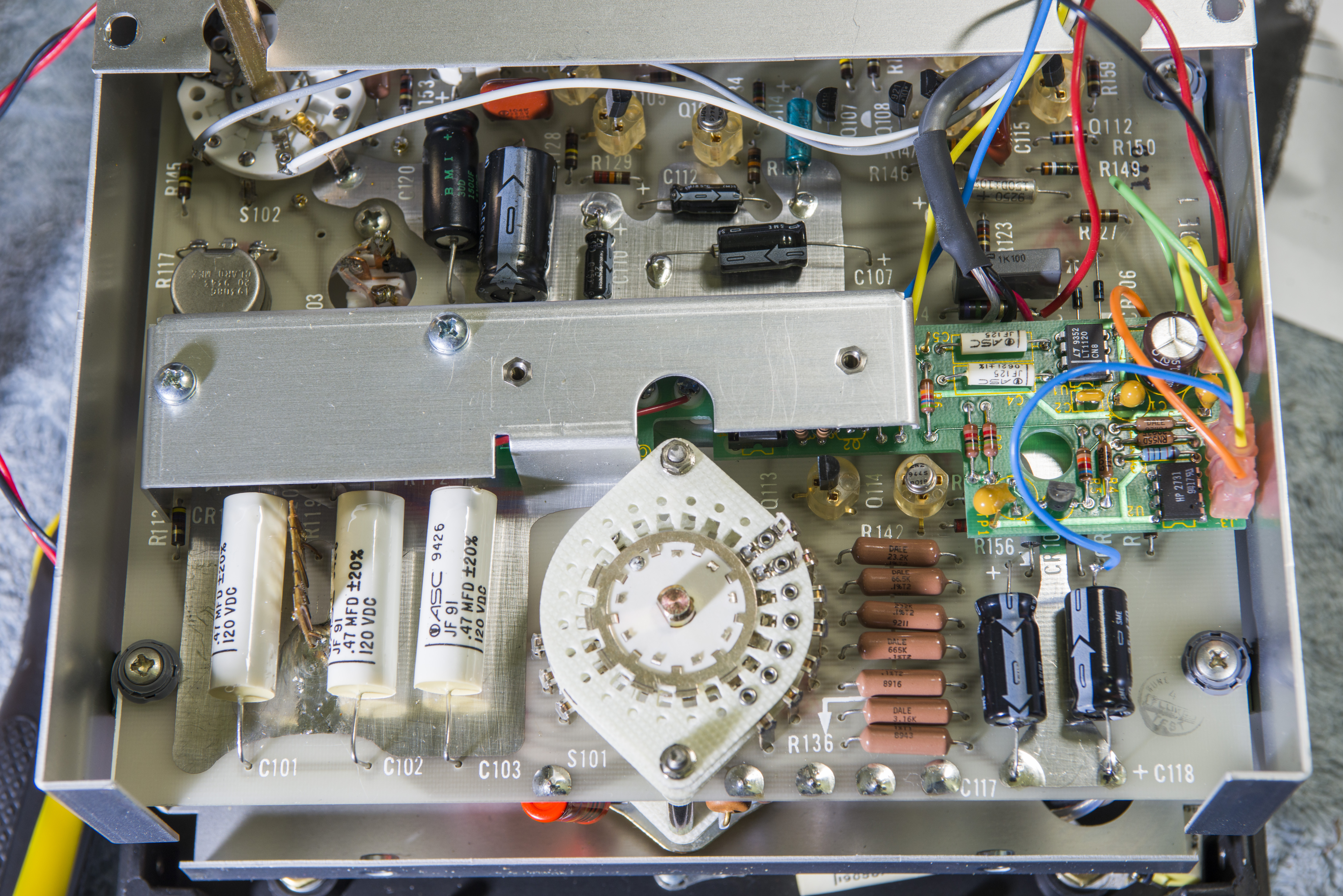
There is plenty space inside, so usual good quality Chemi-Con radial capacitors were used instead of original axial type. I used 470µF 63V instead of original 470µF 25V and 6.3V caps.

Everything inside is very clean, not a single mark of dust, as there is no vent holes or fan in this device.

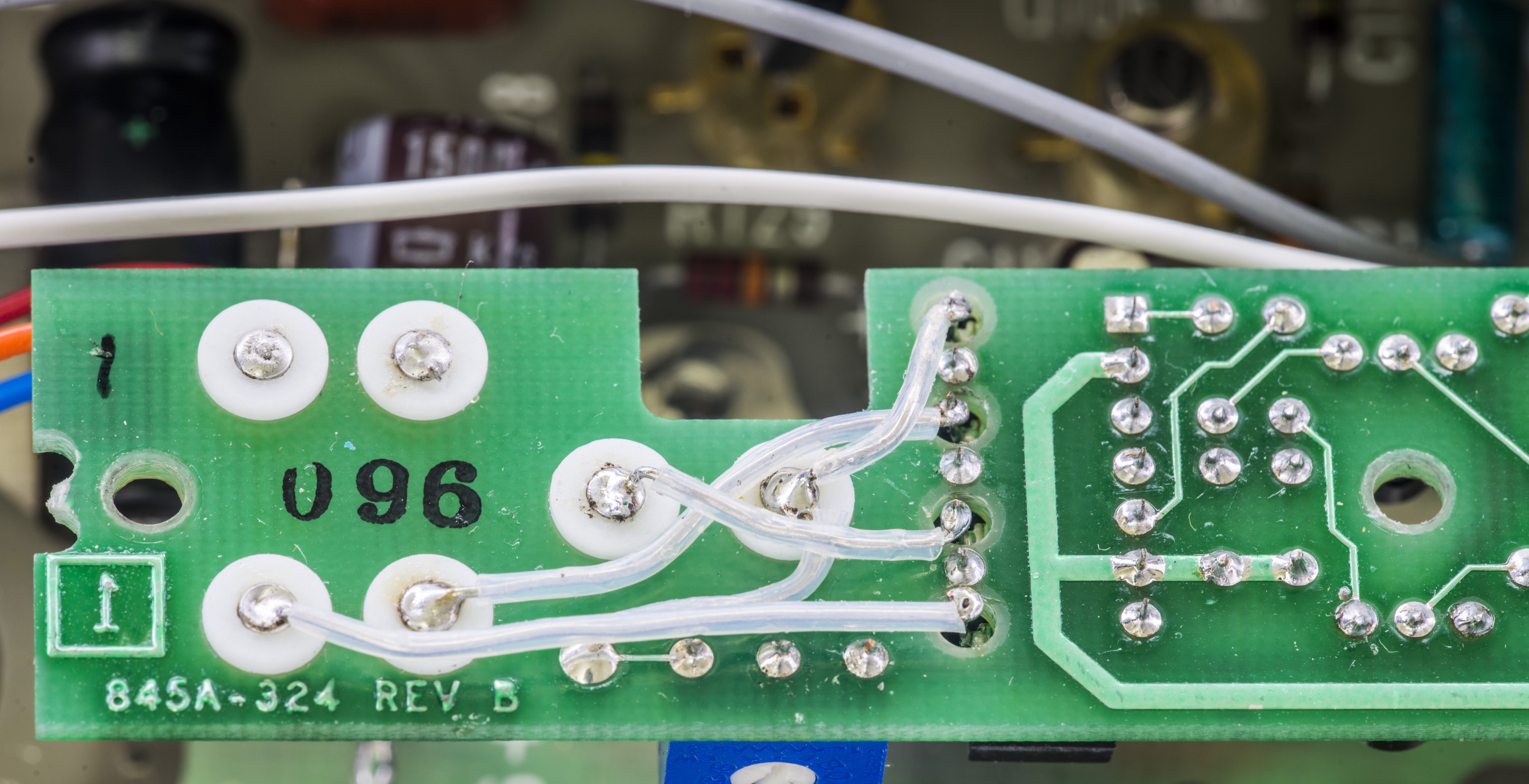
Some decent resistors are installed directly on range switch, including large high voltage 90 MΩ monster with golden leads. Most critical wiring protected by Teflon insulation and soldered to Teflon PCB standoffs.


Calibration procedure
Manual section 4-20 have simple calibration procedure. Model 845 should be calibrated once every year. It is recommended that if component replacement is performed, the Model 845 should be re-calibrated. Test and alignment points are illustrated in instruction manual.
Only single +10.000 VDC reference source is required for calibration.
- - Connect stable DC reference voltage source to Model 845 input. Positive source terminal connected to INPUT, negative source terminal connected to COMMON + GUARD.
- - Set Model 845 controls to POWER = ON, OPR/ZERO = OPR, RANGE = 10 VOLTS
- - Enable +10.000 VDC output on a DC reference voltage source.
- - Adjust R151 for full-scale deflection (+10) on the Model 845 meter
There is also chopper frequency 84 Hz adjustment procedure
- - Set Model 845 controls to POWER = ON
- - Connect oscilloscope or frequency counter between test point TP10 and ground
- - Adjust R206 until the oscilloscope waveform has a time period of 12 milliseconds, or 84 Hz.
Performance test
Here are some graph logs with HP 3458A sampling Fluke 845AB isolated output.
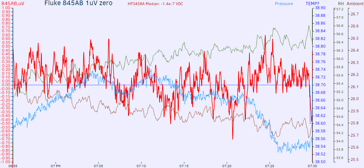
Settings: Fluke 845AB Range: 1 µV, OPR switch = ZERO, 3458A DCV auto, 10 NPLC, AZERO ON
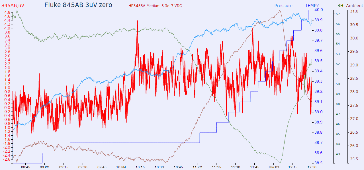
Settings: Fluke 845AB Range: 3 µV, OPR switch = ZERO, 3458A DCV auto, 10 NPLC, AZERO ON
Leakage resistance test
Test leakage of Model 845 will require +10V reference source.
- - Connect positive source output to Model 845 INPUT, and negative source output to Model 845 EARTH terminal.
- - Set Model 845 controls to POWER = ON, OPR/ZERO = OPR, RANGE = 300 µV
- - Model 845 meter should indicate not more than 100 µV, which correspond to leakage resistance 1012 Ω. Allow sufficient time for meter to stabilize.
Tweaks and modifications
In this section we will discuss possible improvements to this null-meter.
To be done, stay tuned…
Conclusion
Unit was repaired and working well, and became a nice addition to our lab. Feel free to ask any questions in comments!
Projects like this are born from passion and a desire to share how things work. Education is the foundation of a healthy society - especially important in today's volatile world. xDevs began as a personal project notepad in Kherson, Ukraine back in 2008 and has grown with support of passionate readers just like you. There are no (and never will be) any ads, sponsors or shareholders behind xDevs.com, just a commitment to inspire and help learning. If you are in a position to help others like us, please consider supporting xDevs.com’s home-country Ukraine in its defense of freedom to speak, freedom to live in peace and freedom to choose their way. You can use official site to support Ukraine – United24 or Help99. Every cent counts.
Modified: Nov. 22, 2018, 10:01 a.m.