- Intro
- Disclaimer
- Manuals and service information
- Exterior
- Design and internal design review
- Firmware
- Repair workflow
- Conclusion and summary
Intro
Keithley is well known brand in low-current/high-sensitivity instrumentation. They invented and designed many related instruments and today part of Tektronix, still providing solutions for science, semiconductor and analog application projects. When design require measurement of very high resistance, starting from Megaohms or testing sensitive high-impedance circuit regular DMM cannot fullfil the task. Even typical 10 MΩ of typical DMM input impedance may ruin the measurement results, or even overload the circuit. Electrometers are special variant of the meter, designed with main purpose to have very high input impedance.
Also being niche application tool, these devices are manufactured in far less volumes, require careful labor work for assembly. As result they often cost much more than regular DMM, often over $5000 USD. Current Model 6517B is listed now for $8270 USD on Tektronix site. This is $1400 more than top of the line, 8½-digit Keithley Model 2002 DMM.
Today we will attempt to service electrometer after unsuccessful 3rd-party repair, Model 6517A.

Image 1: Keithley 6517A face, as is received for service
Disclaimer
Redistribution and use of this article, any part of it or any images or files referenced in it, in source and binary forms, with or without modification, are permitted provided that the following conditions are met:
- Redistributions of article must retain the above copyright notice, this list of conditions, link to this page (https://xdevs.com/fix/k6517a_u2/) and the following disclaimer.
- Redistributions of files in binary form must reproduce the above copyright notice, this list of conditions, link to this page (https://xdevs.com/fix/k6517a_u2/), and the following disclaimer in the documentation and/or other materials provided with the distribution, for example Readme file.
All information posted here is hosted just for education purposes and provided AS IS. In no event shall the author, xDevs.com site, or any other 3rd party, including Keithley/Tektronix be liable for any special, direct, indirect, or consequential damages or any damages whatsoever resulting from loss of use, data or profits, whether in an action of contract, negligence or other tortuous action, arising out of or in connection with the use or performance of information published here.
If you willing to contribute or add your experience regarding instrument repairs or provide extra information, you can do so following these simple instructions
Manuals references
Model 6517 User’s Manual, July 1995, Rev.D old
Model 6517 User’s Manual, July 1995, Rev.D digitized
Model 6517A Electrometer/High Resistance Meter Getting Started Manual
Model 6517A Electrometer User’s Manual, Rev.C
Model 6517A User’s Manual, May 2003, Rev.D
Model 6517A Service Manual, April 1999, RevB. no schematics
Procedure to Properly Zero the Model 6517A
Model 6517A Specifications page, 3/5/2009, Rev.D 2009.pdf
Model 6517B Electrometer User’s Manual 6517B-900-01 Rev. A / June 2008
Model 6517B Reference Manual 6517B-901-01 Rev. B / June 2009 2009—Ref.pdf
Differences between the new 6517B and the 6517A version
Exterior
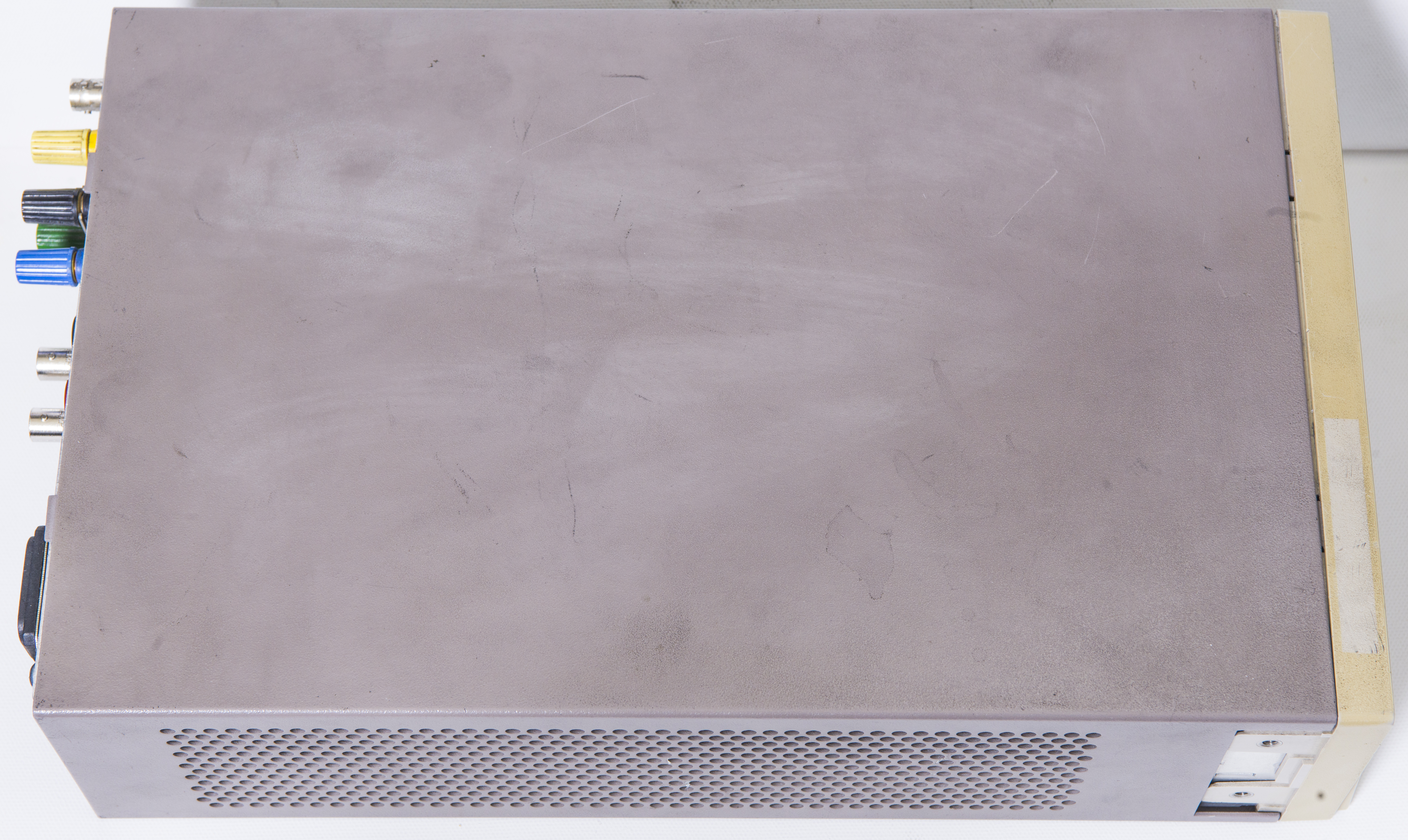

Image 2-3: As received, dirty case and unit parts.
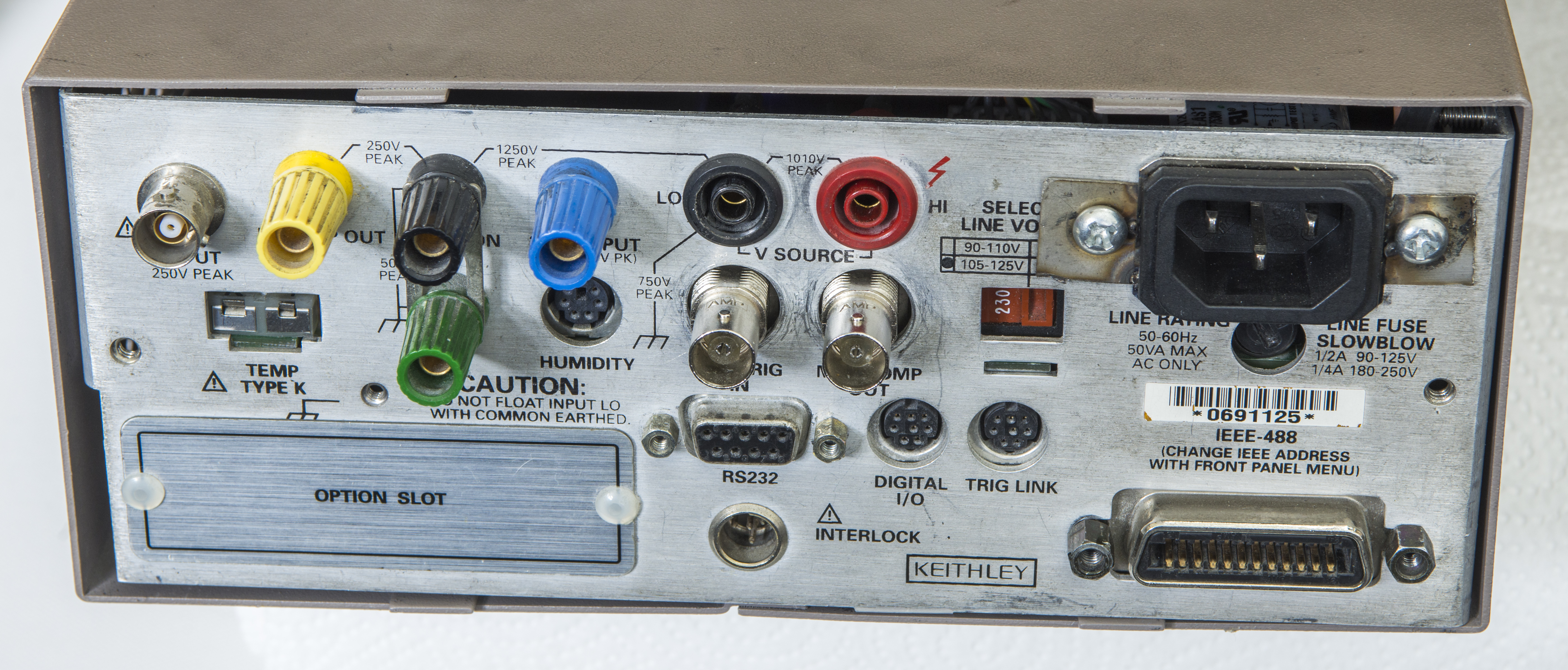
Image 4: Rear connectors
This electrometer is 100% silent, as it does not have any cooling fans.
Design and internal design review
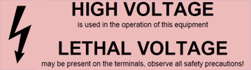
-1200 and +1200VDC voltages present inside of this electrometer when operation are dangerous and even lethal. Pay attention of what you are doing, and keep all connections fixed and robust. Do not use hands during probing unless checked and absolutely safe. Use tools rated for CAT III operation while servicing high-power and high-voltage circuits in this instrument.

Image 5: Instrument overall block diagram, courtesy Keithley service manual.
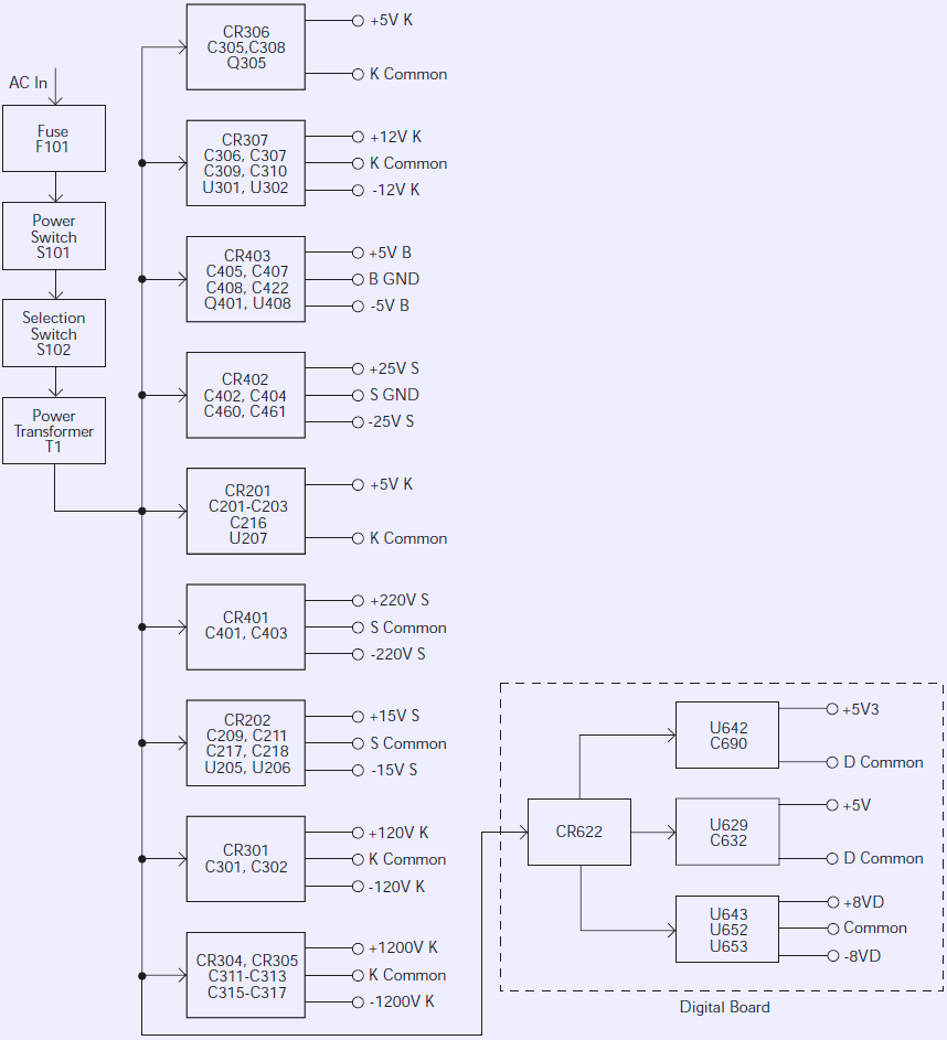
Image 5: Power rails and supplies, courtesy Keithley service manual.
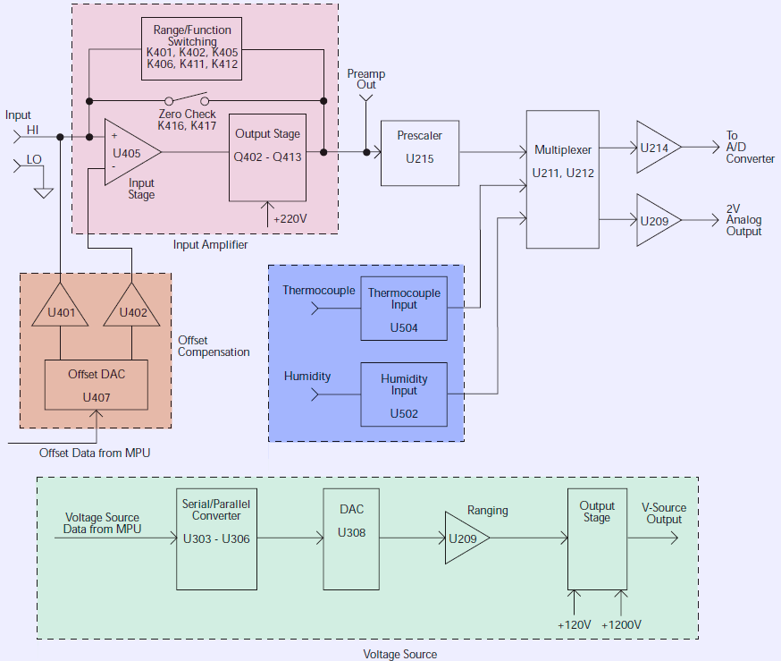
Image 5: Analog isolated domain block diagram, courtesy Keithley service manual.
Damaged parts (and current status):
- Destroyed analog PCB. Replacement WIP
- Fake FETs in voltage source regulator TBD
- Bad DAC TBD
- Bad capacitors TBD
- Mains input CMF assembly not original TBD
- Bad SMT resistors and ruined pads TBD
- Broken VFD glass, no vacuum TBD
- Damaged banana jacks TBD
- Dirty yellow front panel TBD
- Unit out of calibration TBD
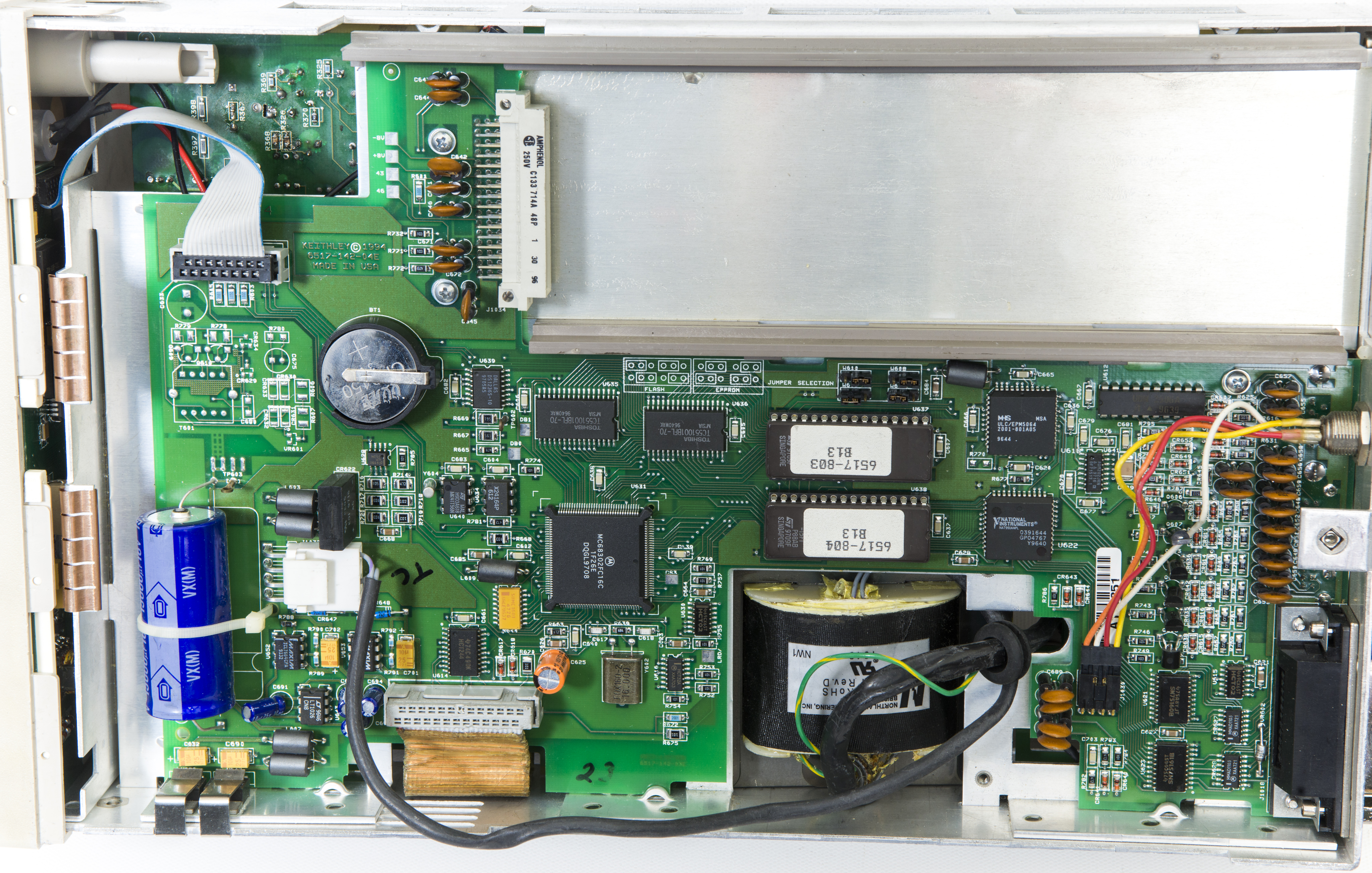
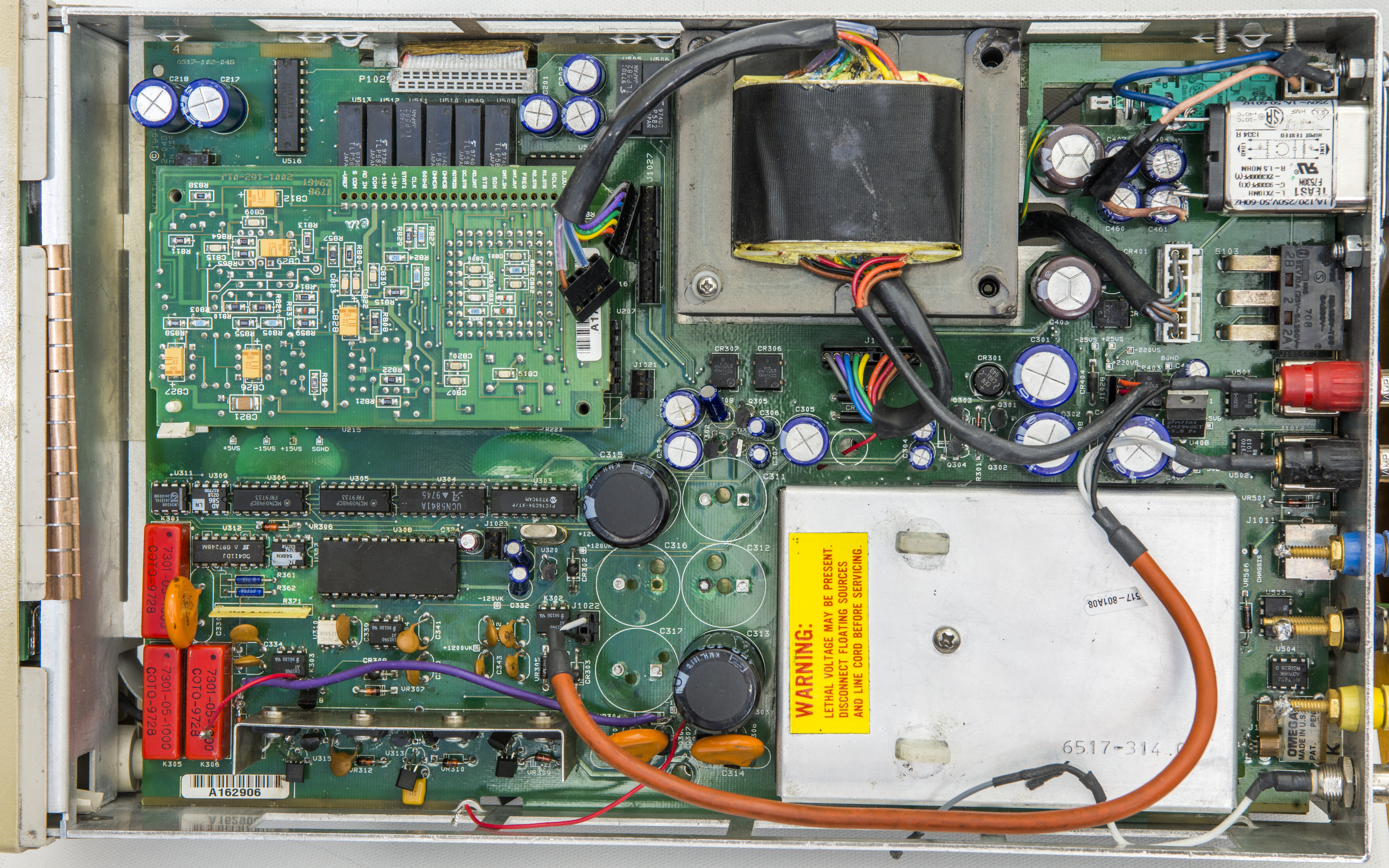
Image 5: Digital board on bottom side and analog assembly on top side
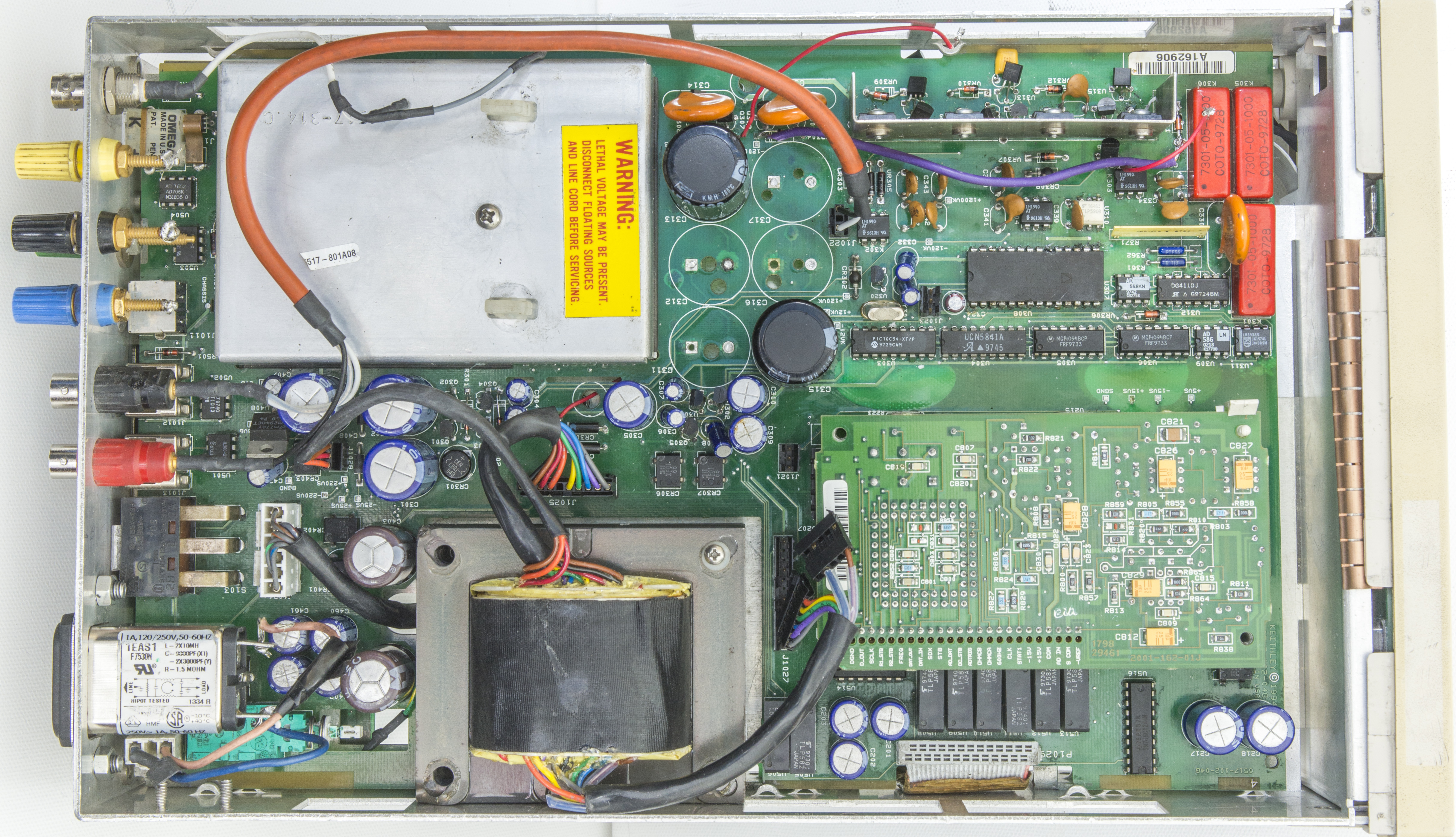
Image 5: Digital board on bottom side and analog assembly on top side
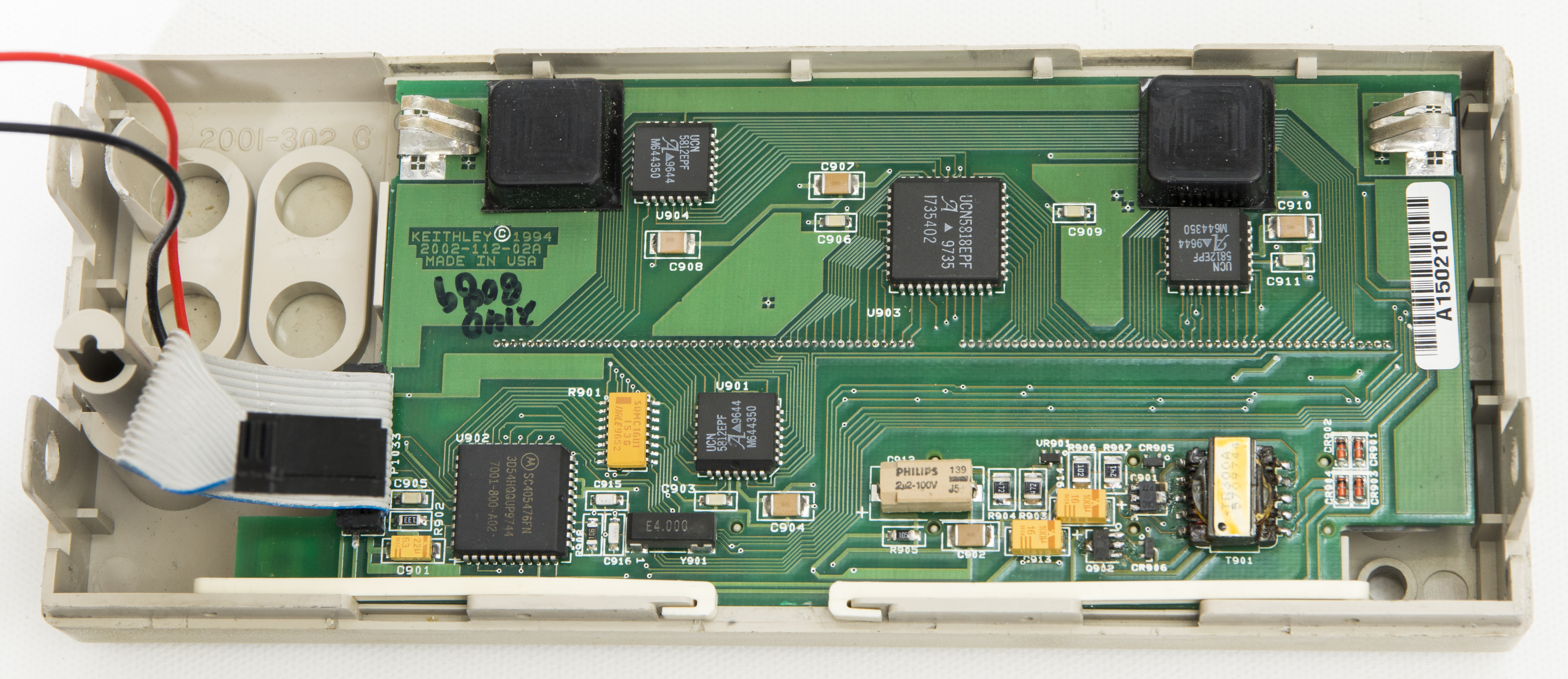
Image 5: Digital board on bottom side and analog assembly on top side
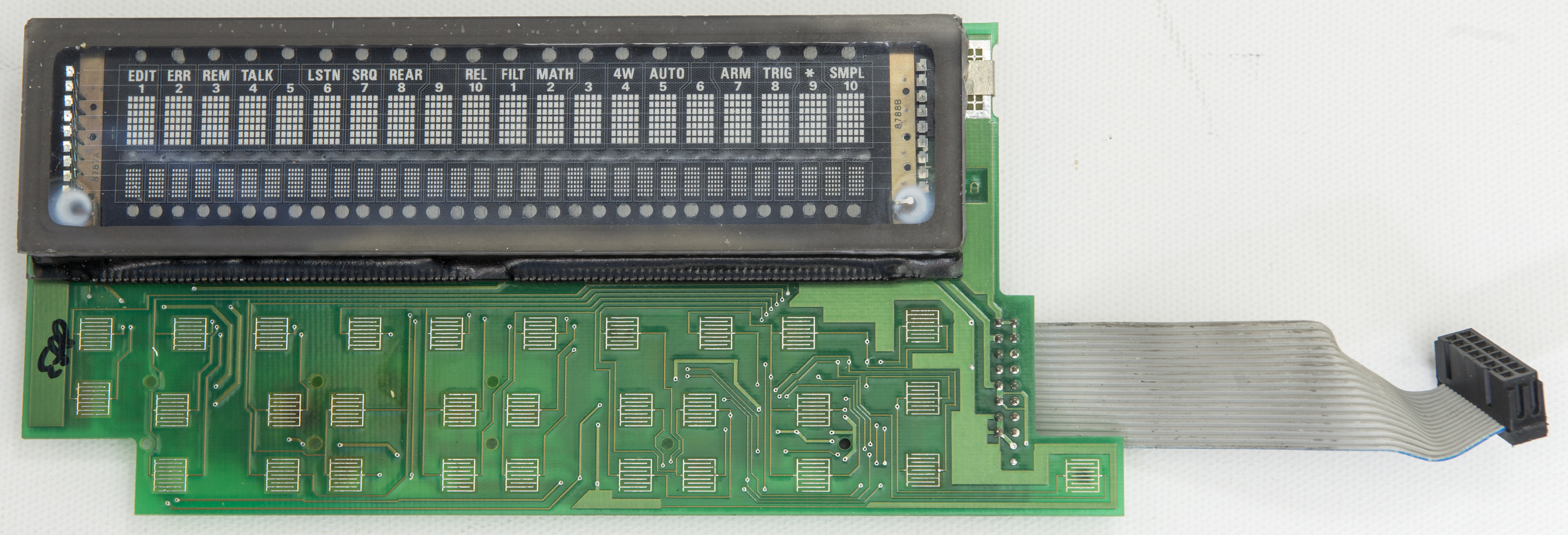
Image 5: Digital board on bottom side and analog assembly on top side
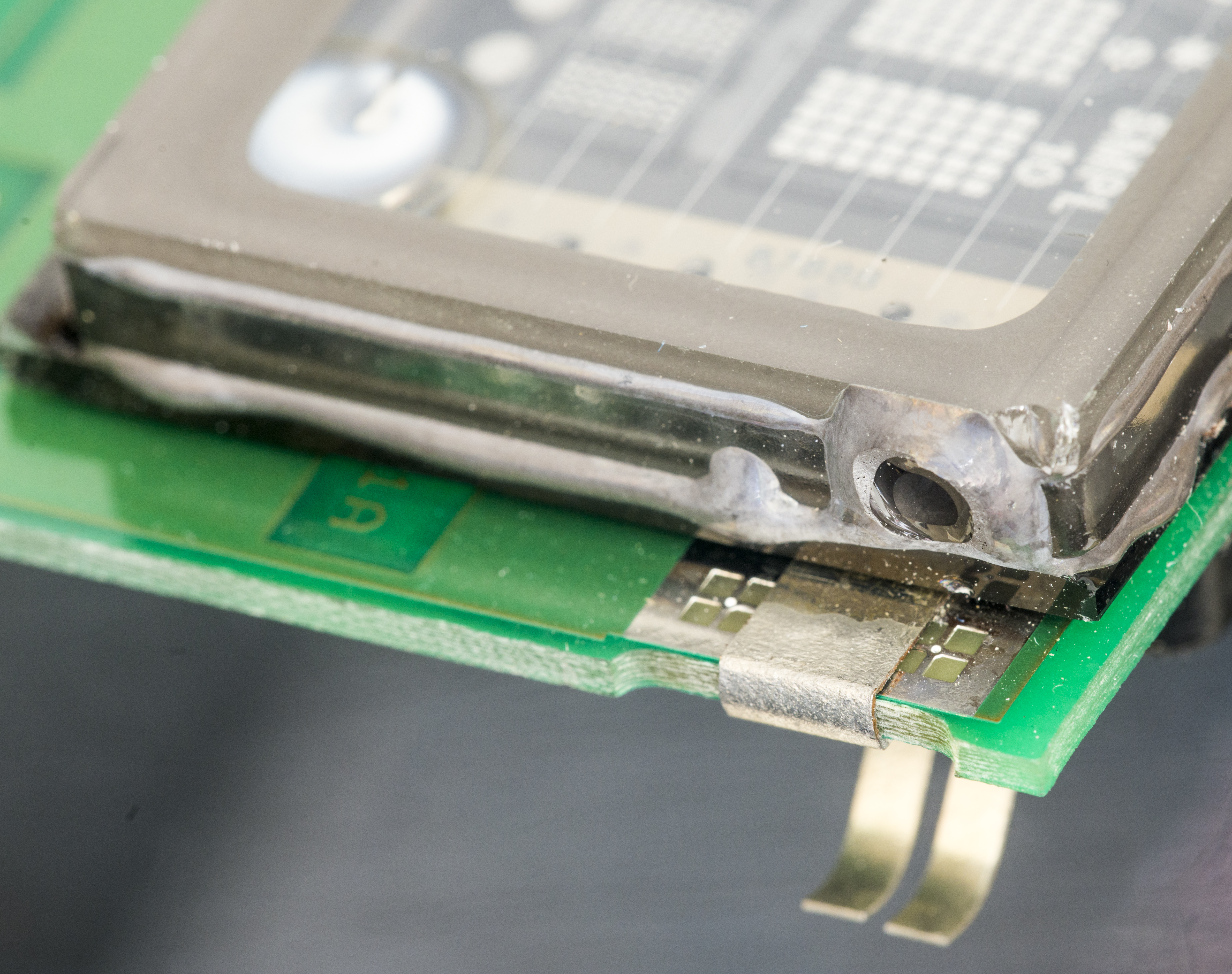
Image 5: Digital board on bottom side and analog assembly on top side

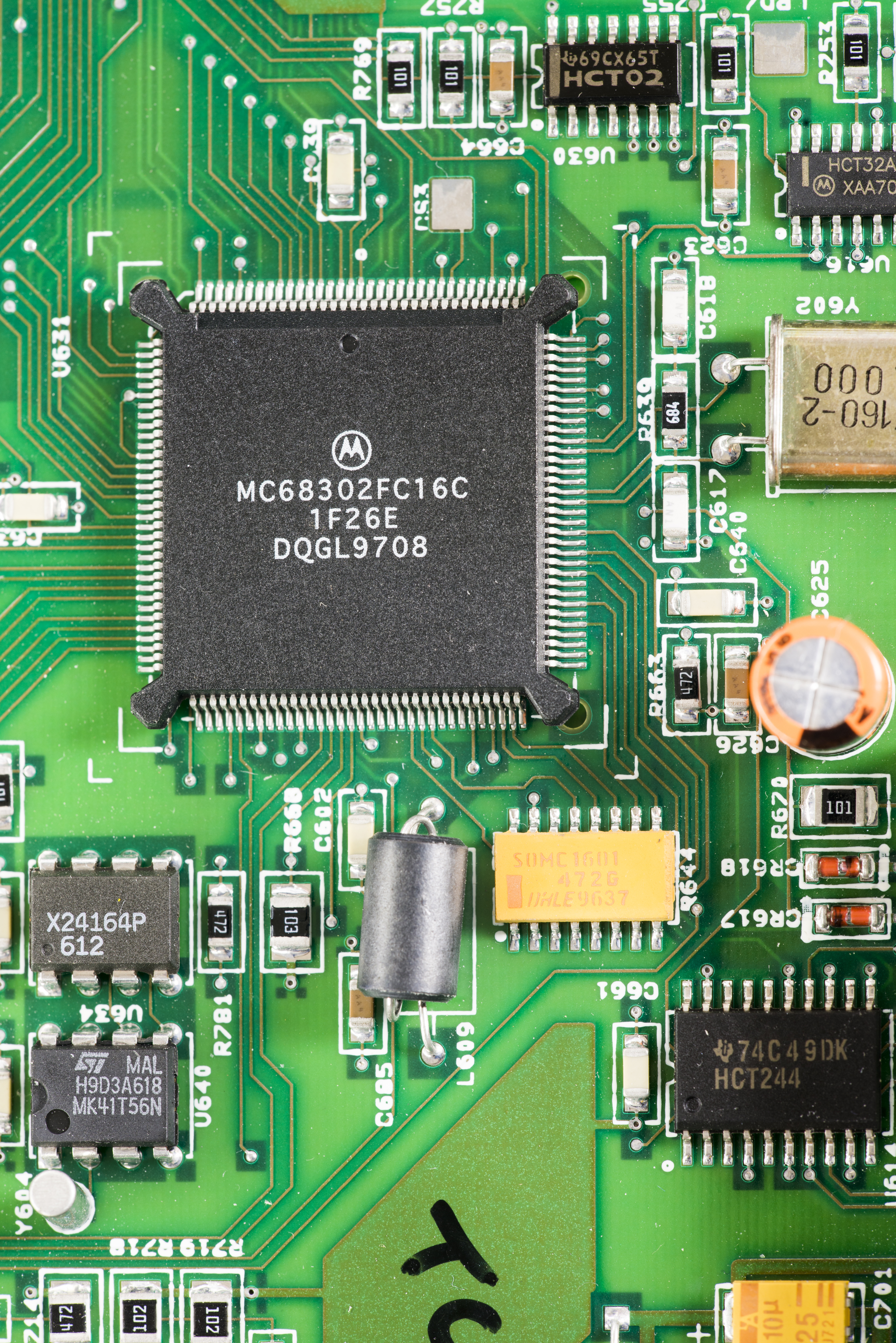
Image 5: Digital board on bottom side and analog assembly on top side
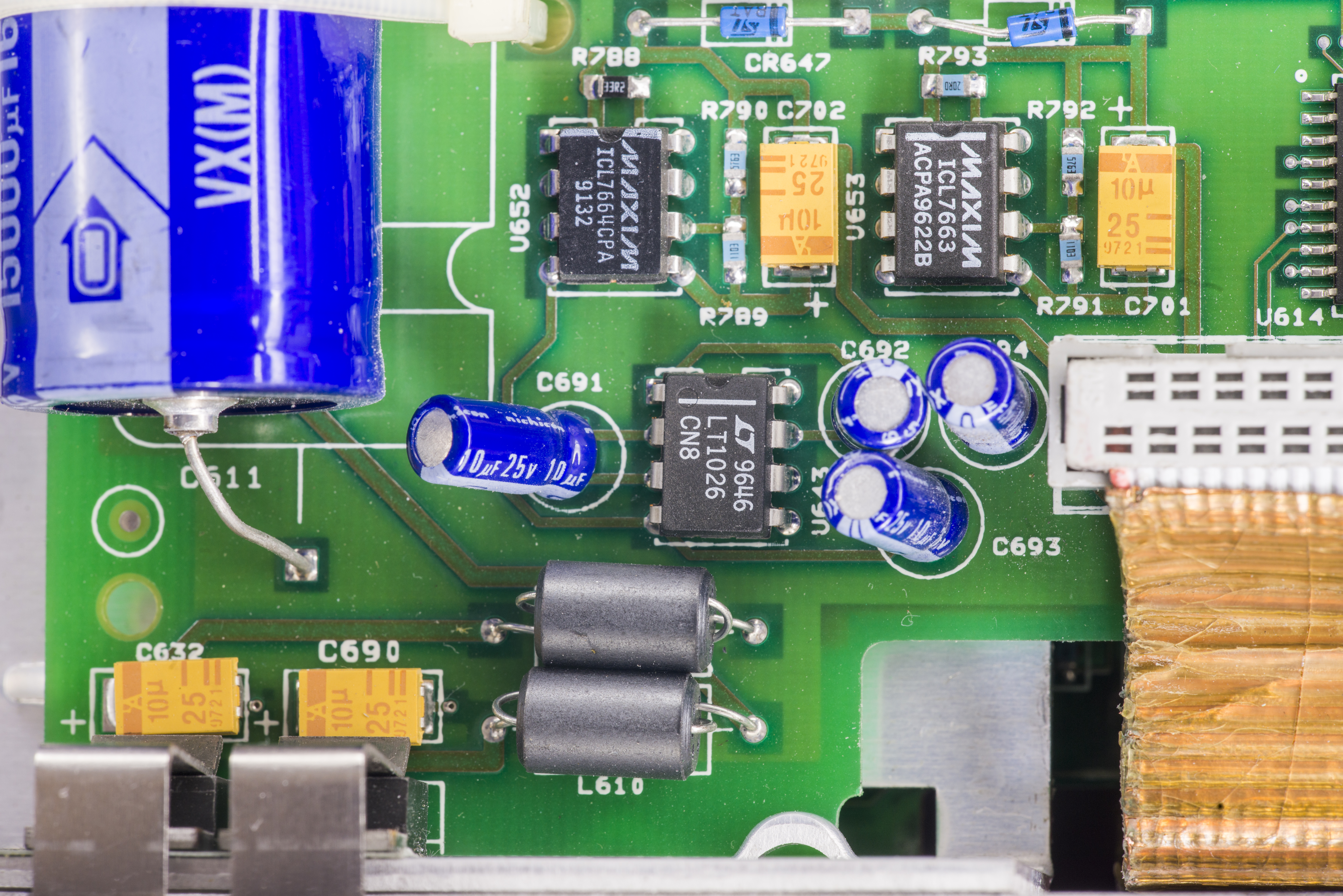
Image 5: Digital board on bottom side and analog assembly on top side
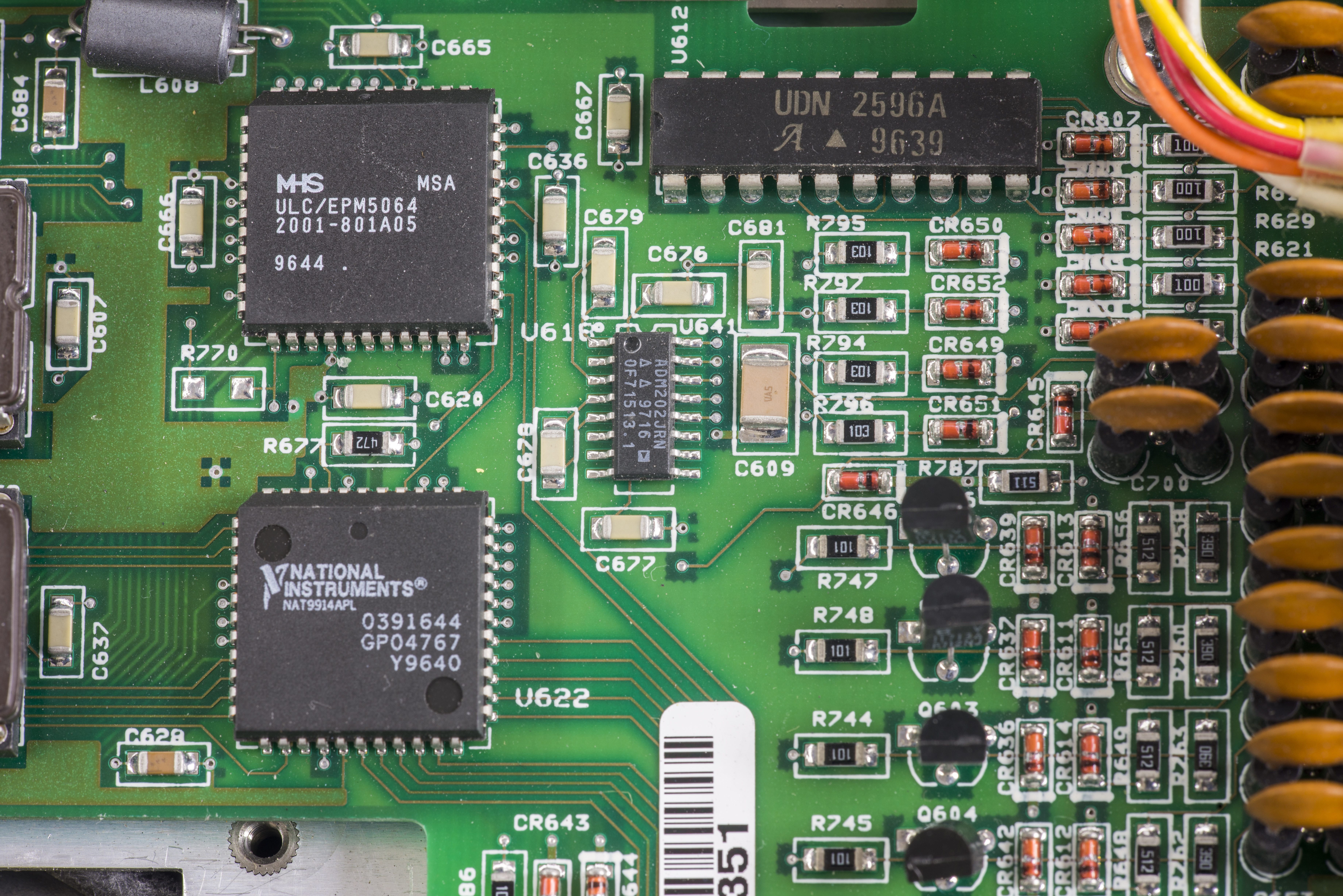
Image 5: Digital board on bottom side and analog assembly on top side
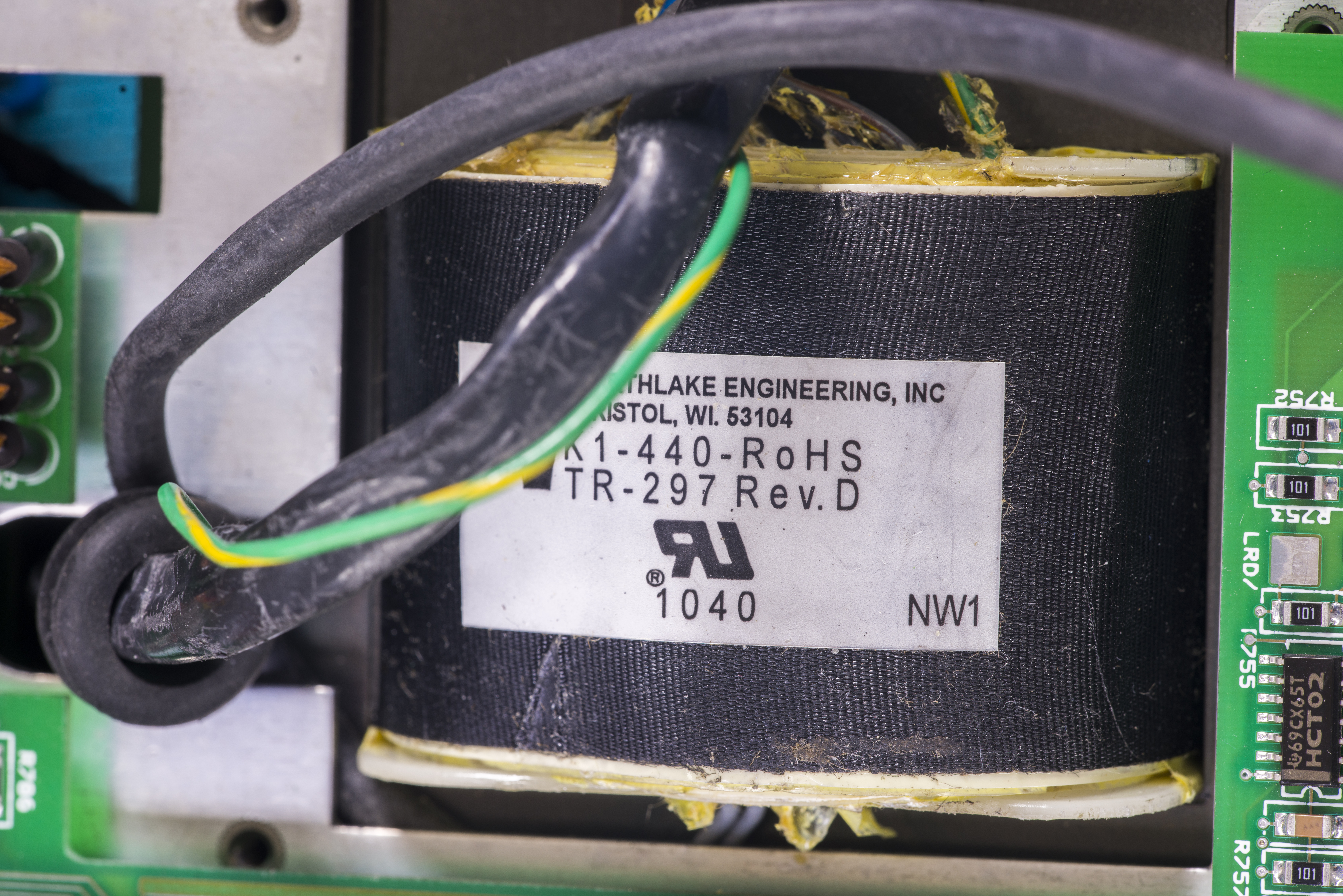

Image 5: Digital board on bottom side and analog assembly on top side
ADC here is very same module that used in 7½-digit Keithley 2001 DMM. Module have ALTERA EPM7128 in PLCC64 package, configured to 2001-801-A01 RTL clocked from 7.68MHz XO. SPI-like interfaces are used as data interface to digital board. This chip also act as bridge to all analog switches and control muxes between isolated analog and earth-referenced digital domain.
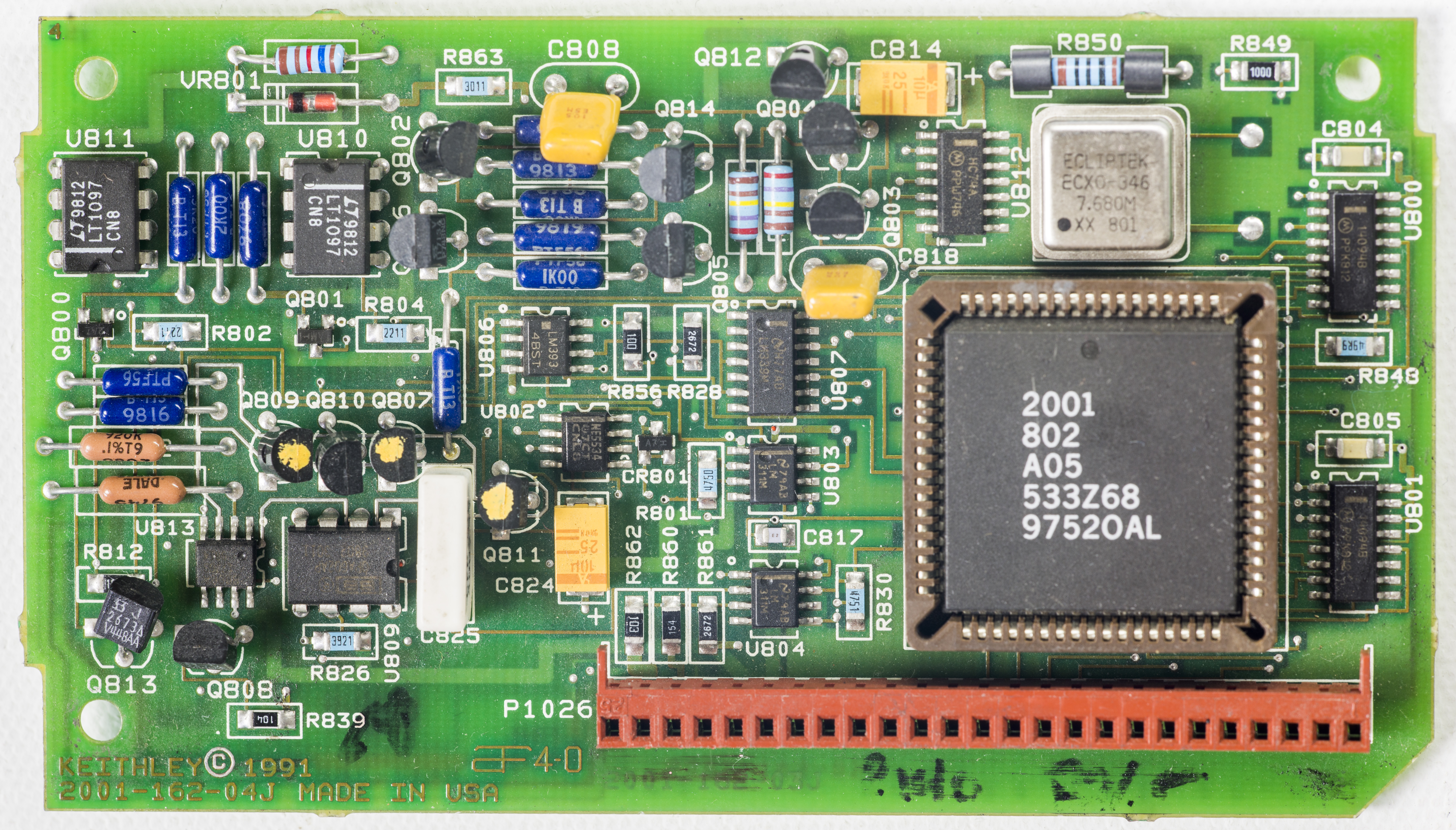
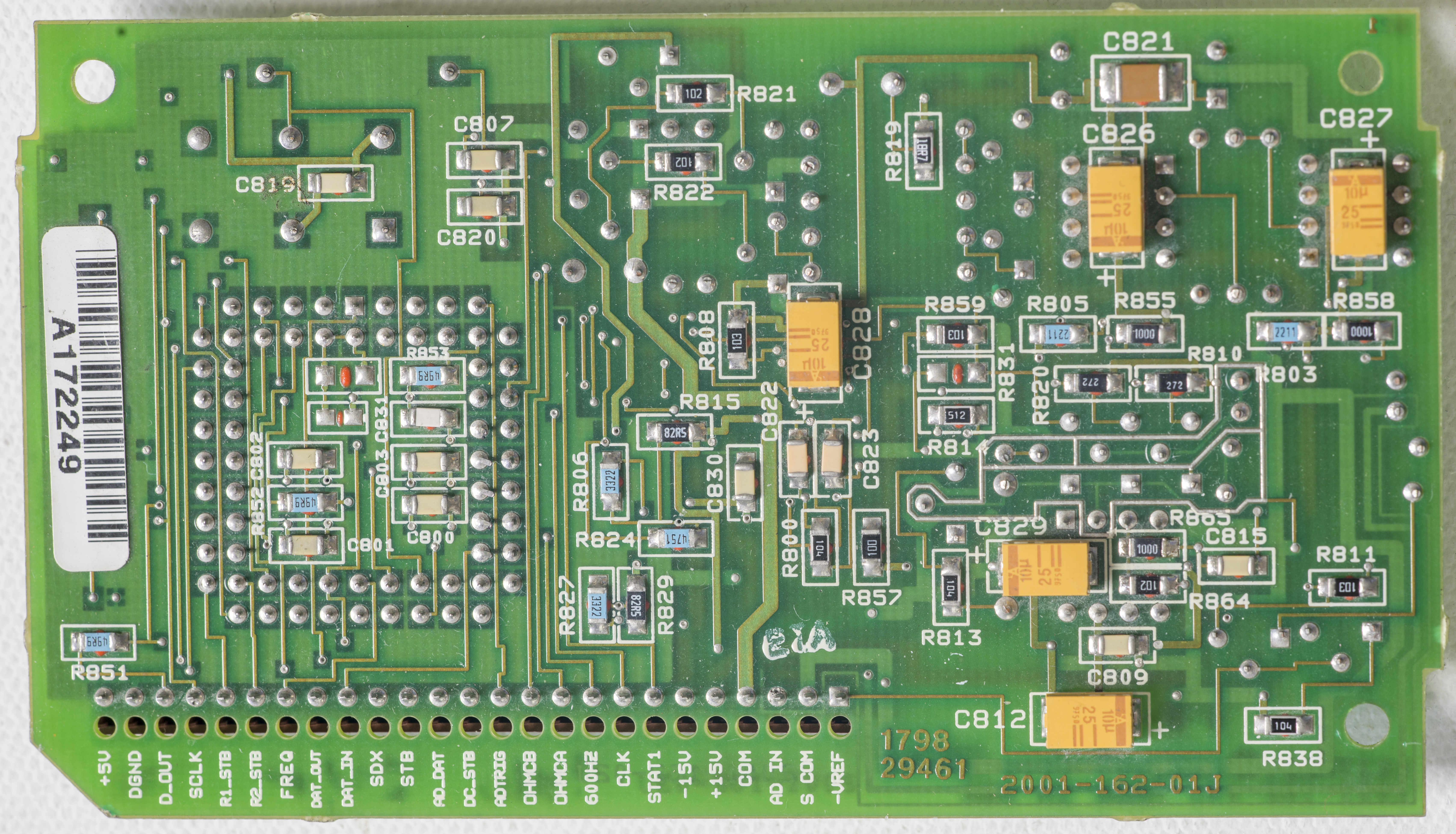
Image 5: A/D Converter and interface bridge
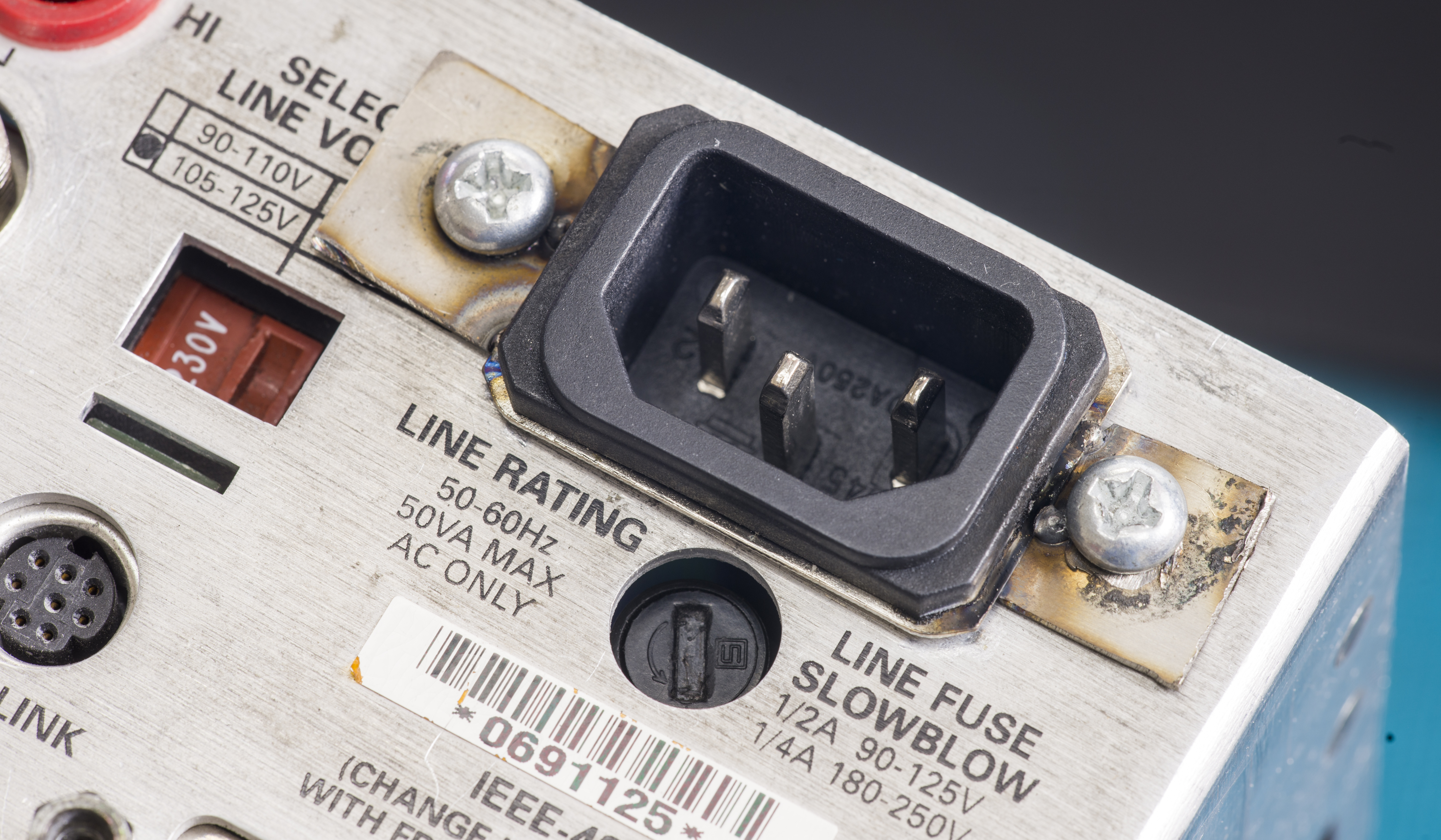
Image 5: A/D Converter and interface bridge
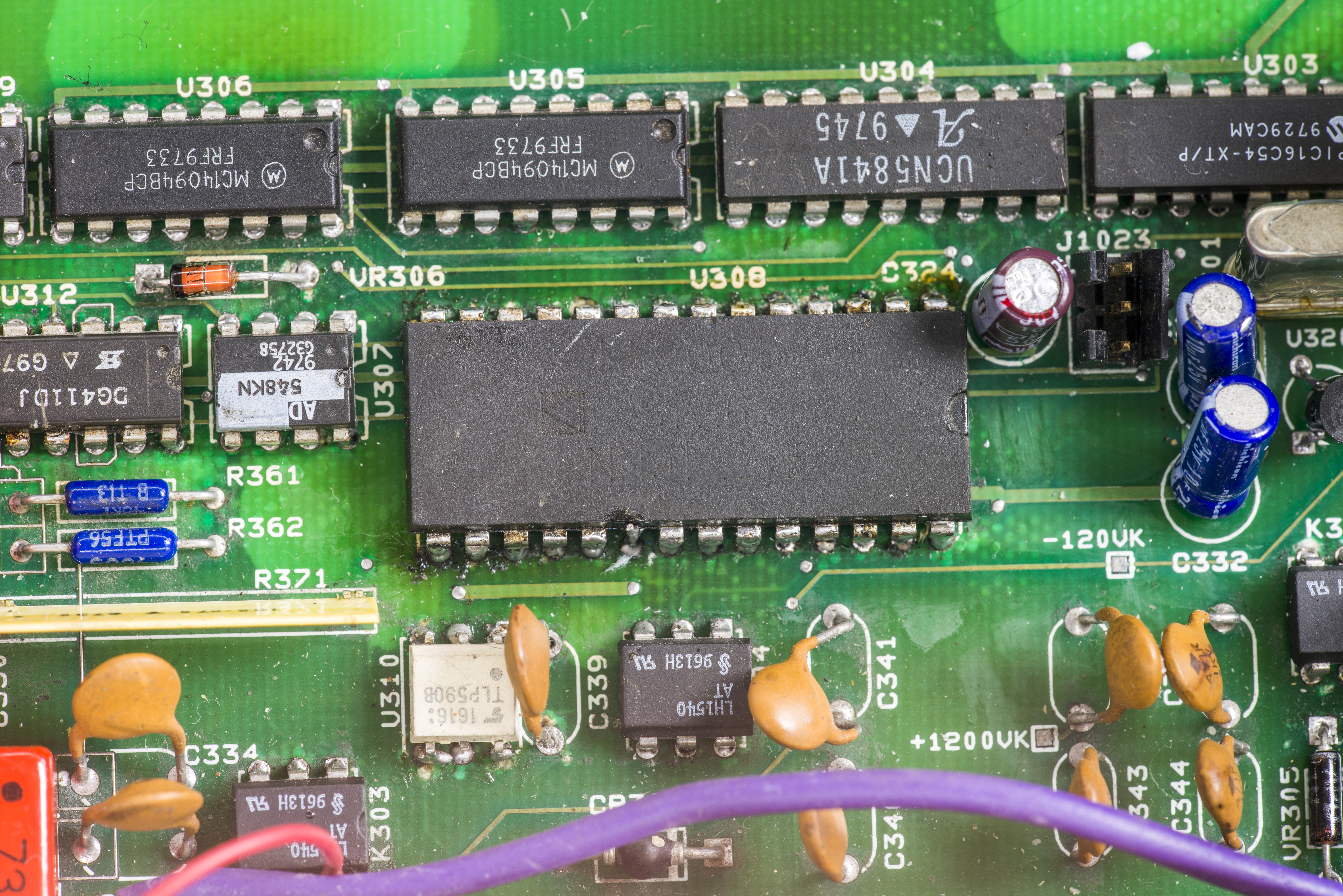
Image 5: A/D Converter and interface bridge
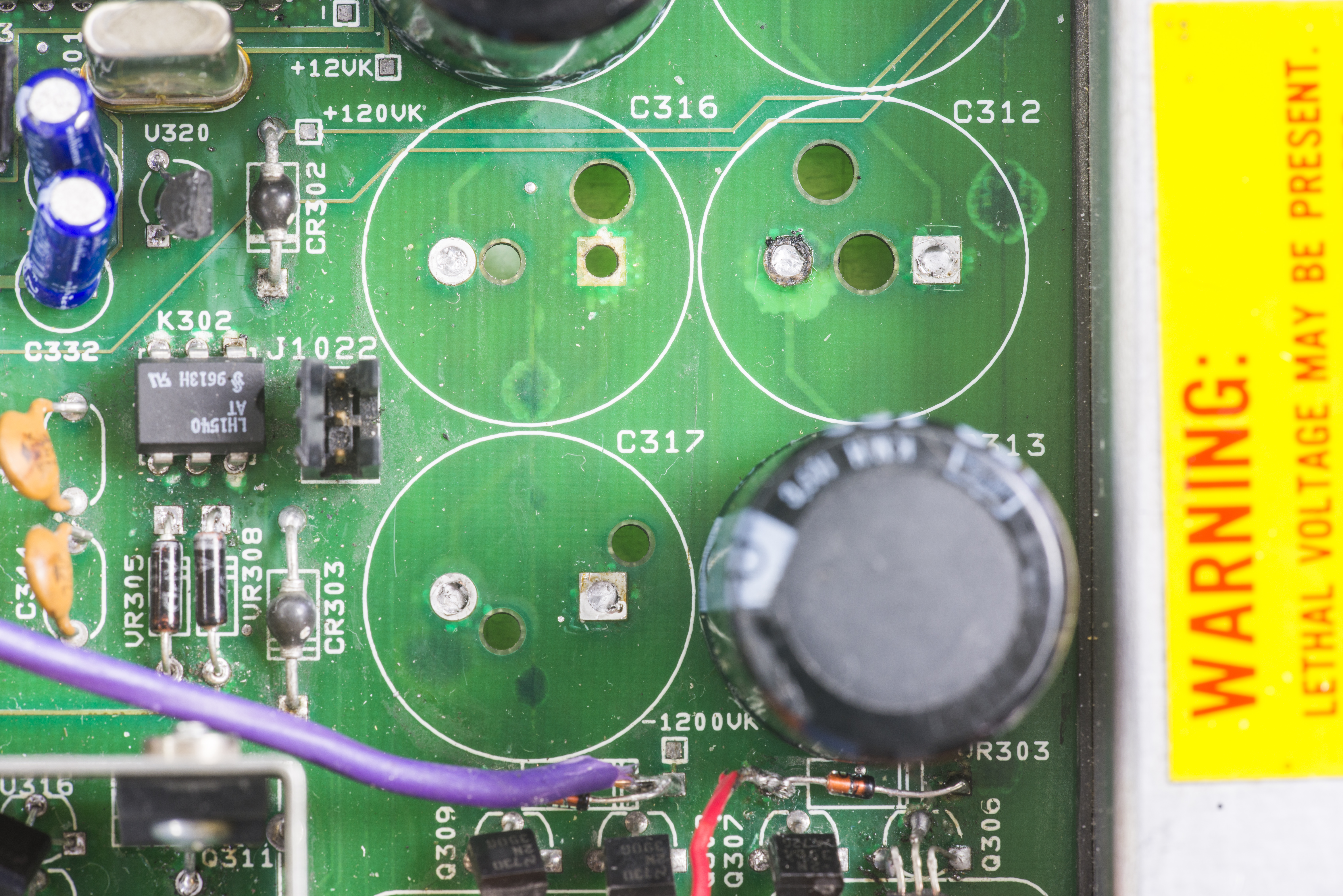
Image 5: A/D Converter and interface bridge
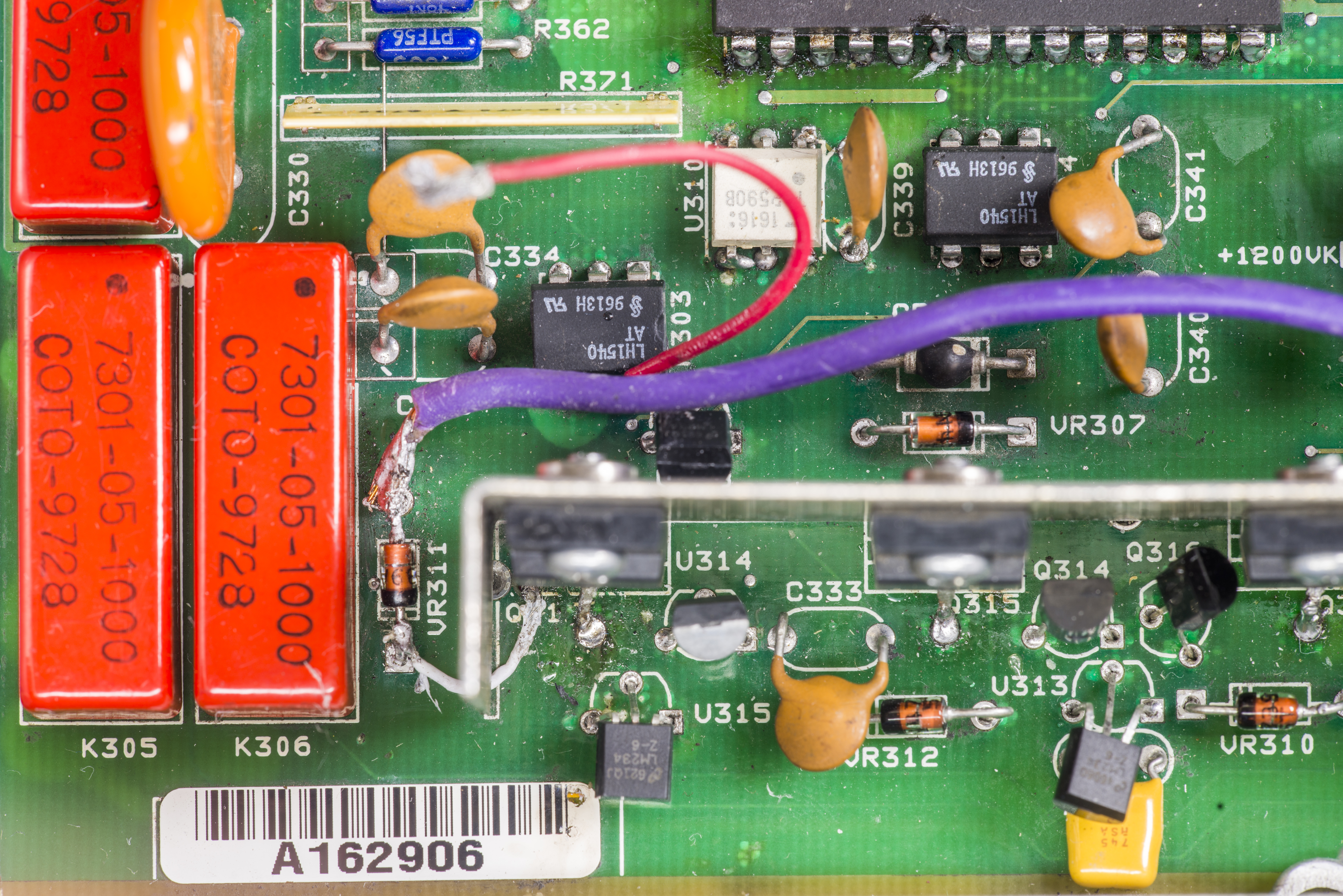
Image 5: A/D Converter and interface bridge

Image 5: A/D Converter and interface bridge

Image 5: A/D Converter and interface bridge

Image 5: A/D Converter and interface bridge
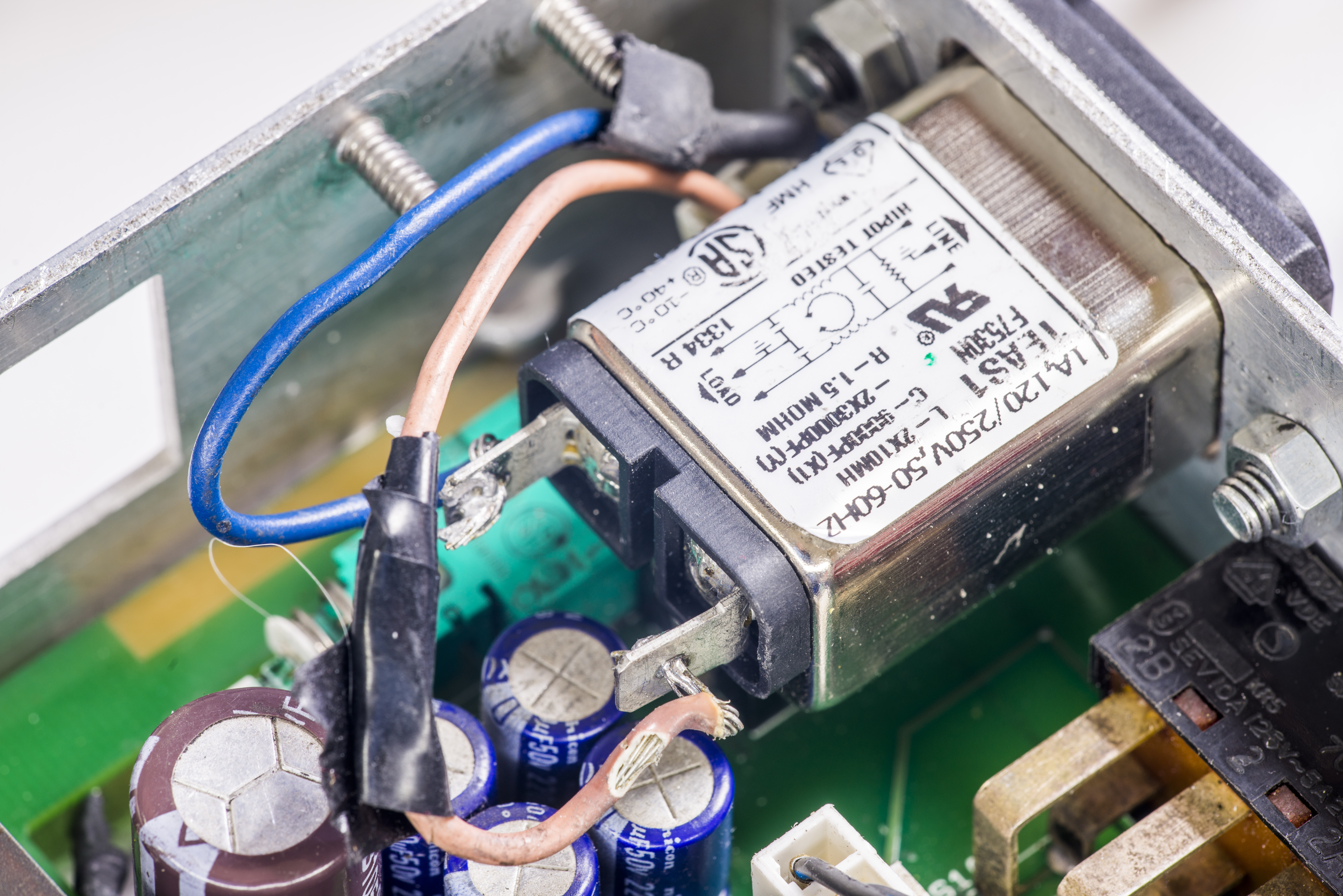
Image 5: A/D Converter and interface bridge
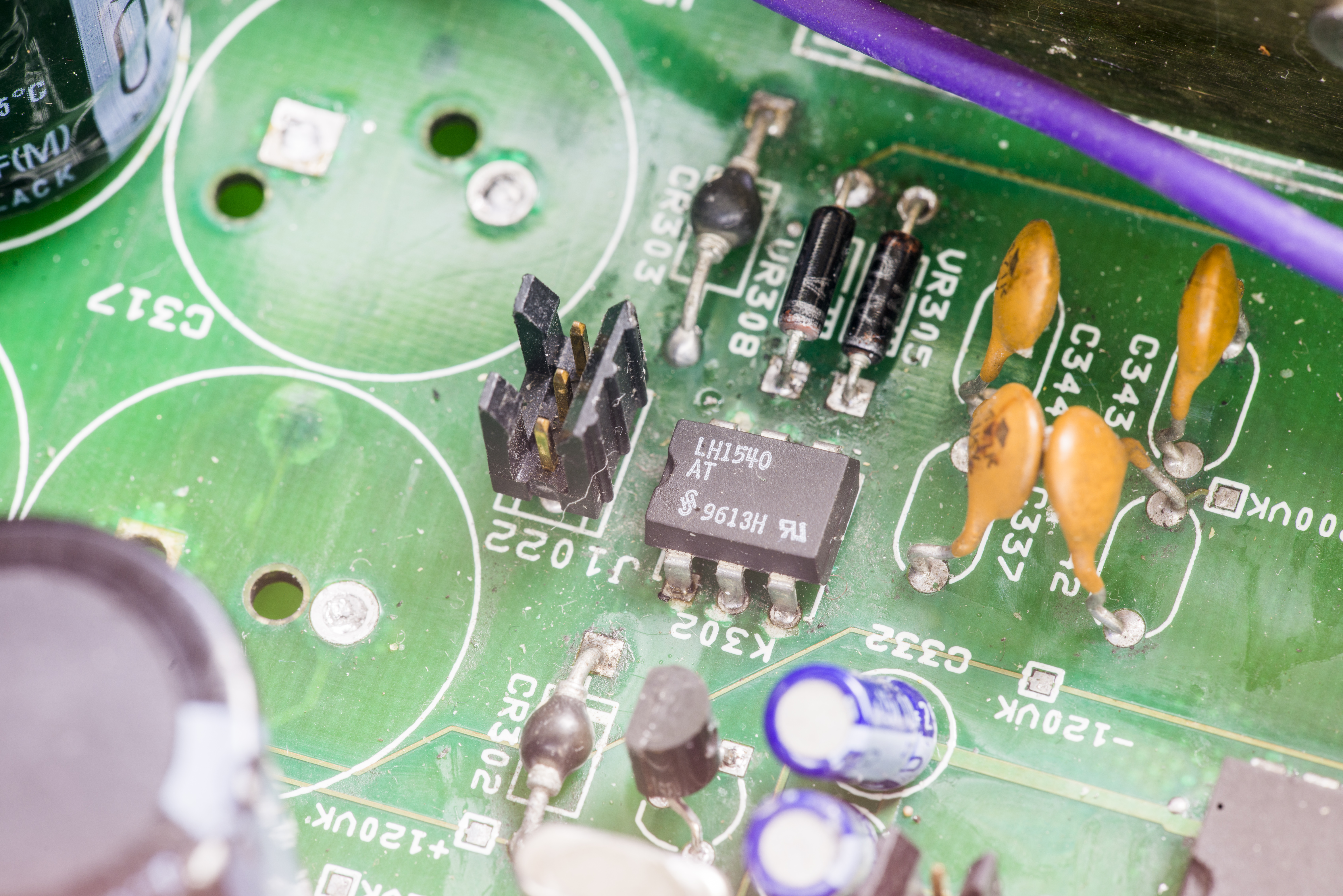
Image 5: A/D Converter and interface bridge

Image 5: A/D Converter and interface bridge
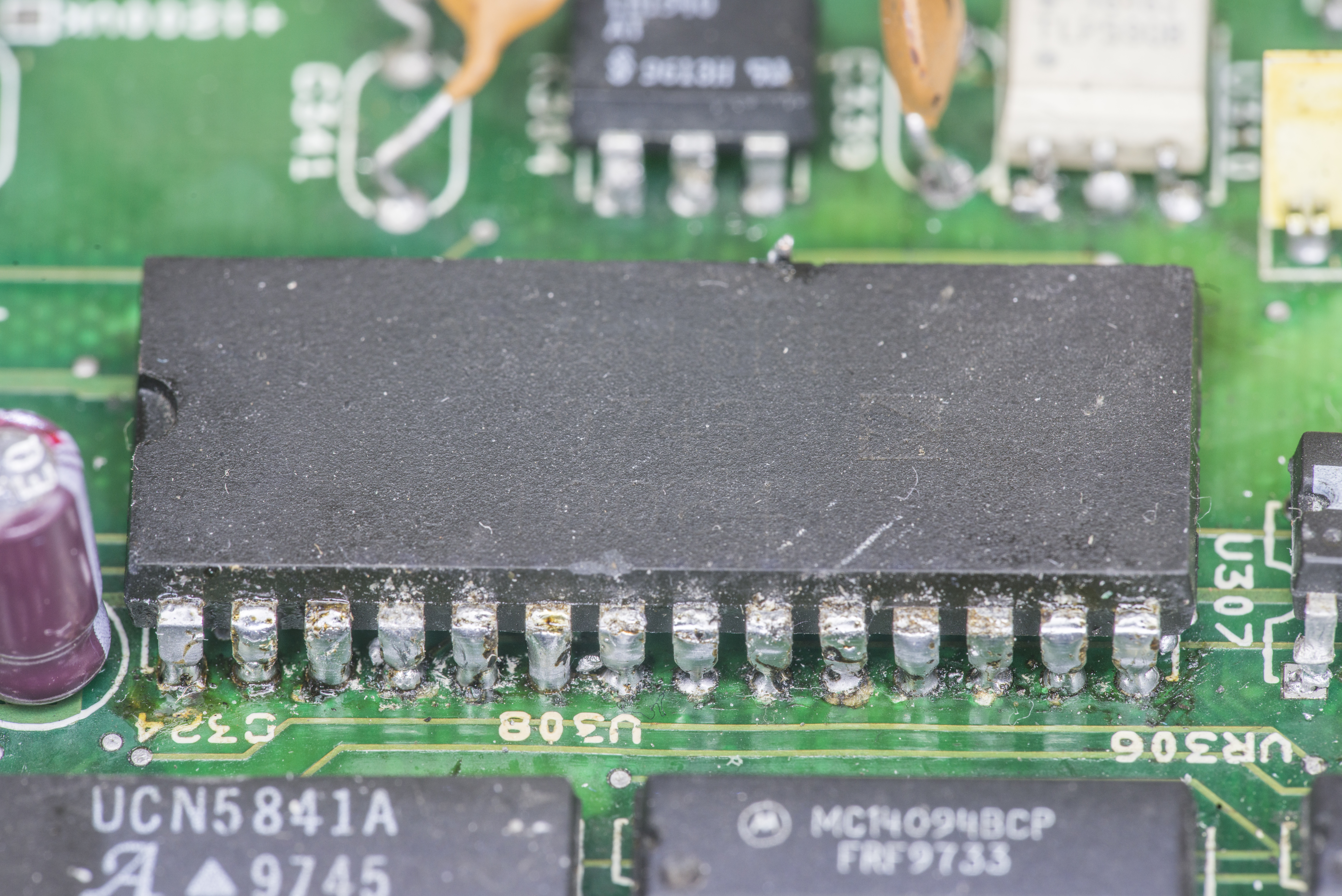
Image 5: A/D Converter and interface bridge
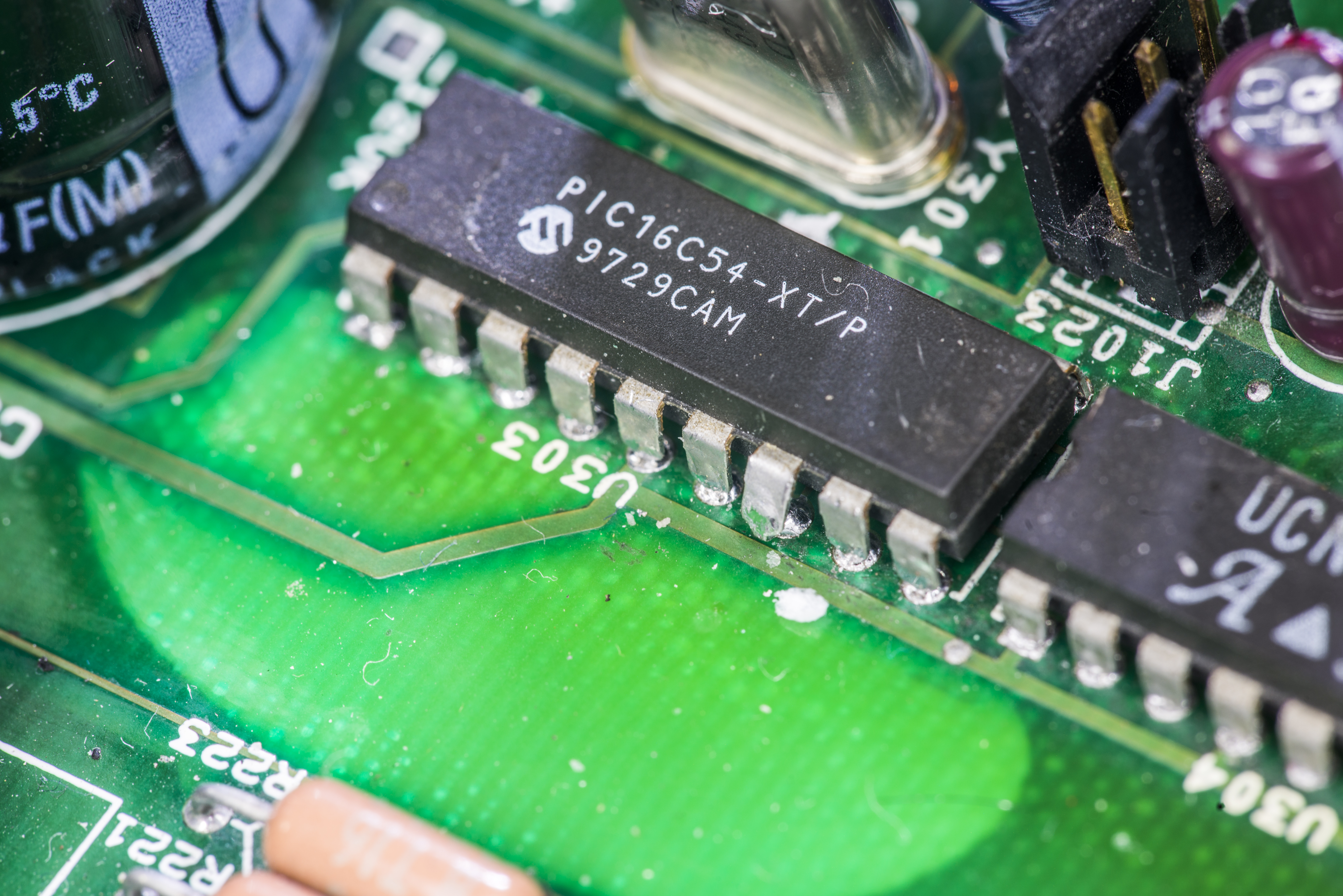
Image 5: A/D Converter and interface bridge
Repair workflow
Review soldering instructions prior to any reworks or soldering on the instrument boards. Failure to apply care during rework may and will cause damages to sensitive circuits and components!
- Use an OA-based non-acid flux, and take care not to spread the flux over unrelated areas of the circuit board.
- Carefully remove the flux from the work areas when the repair has been completed. Use IPA and pure distilled water along with clean foam-tipped swabs or a clean soft brush to remove the flux. Be sure not to wash contaminated flux or water over other PC board areas.
- Once the flux has been removed, swab only the repaired area with methanol, then blow dry the board with dry nitrogen gas.
- After cleaning, the board should be allowed to dry in a +50 °C low-humidity environment for several hours. There should be no residues or foreign particles visible on any surface.
Digital board
Let’s try with easy stuff first, digital board.
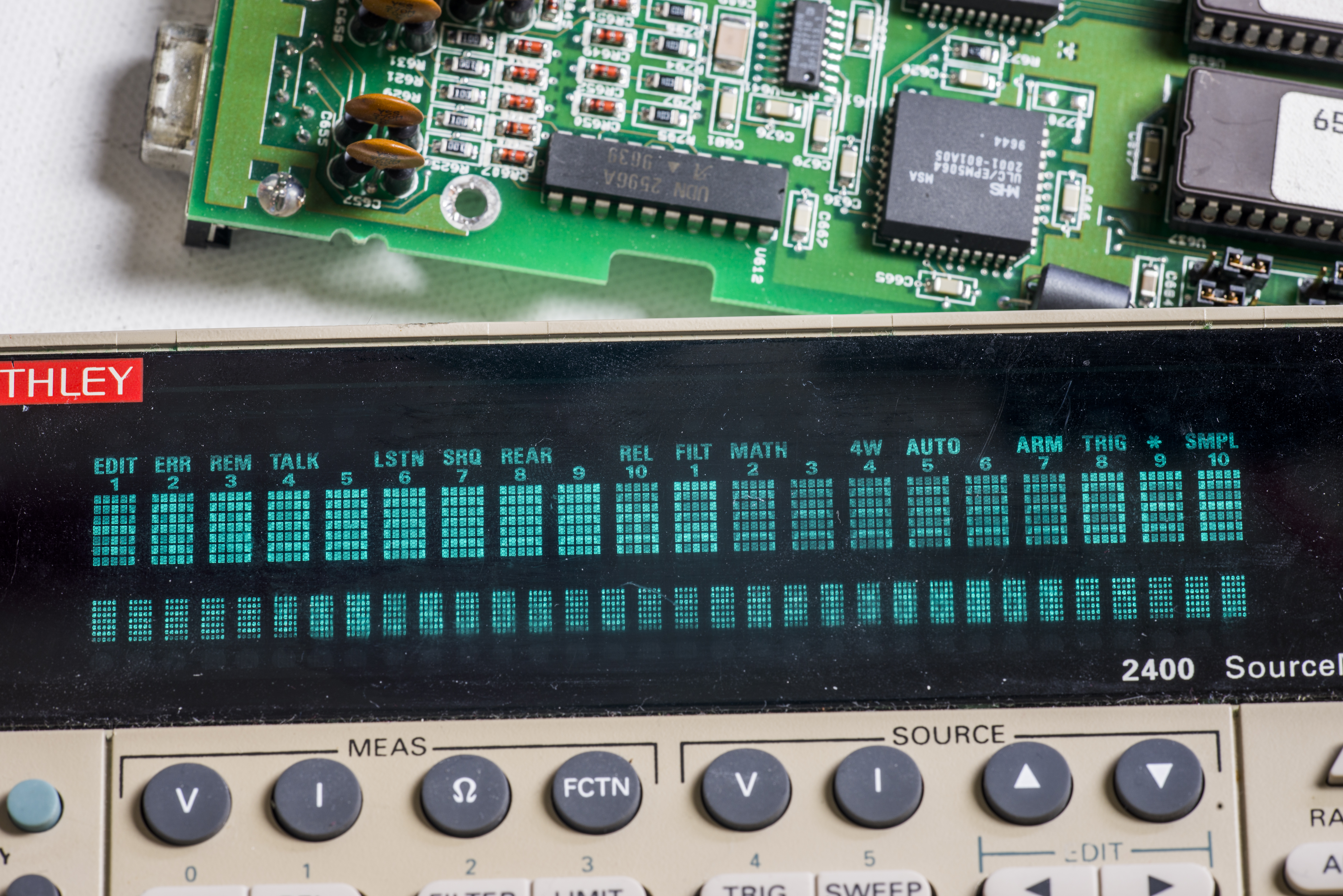
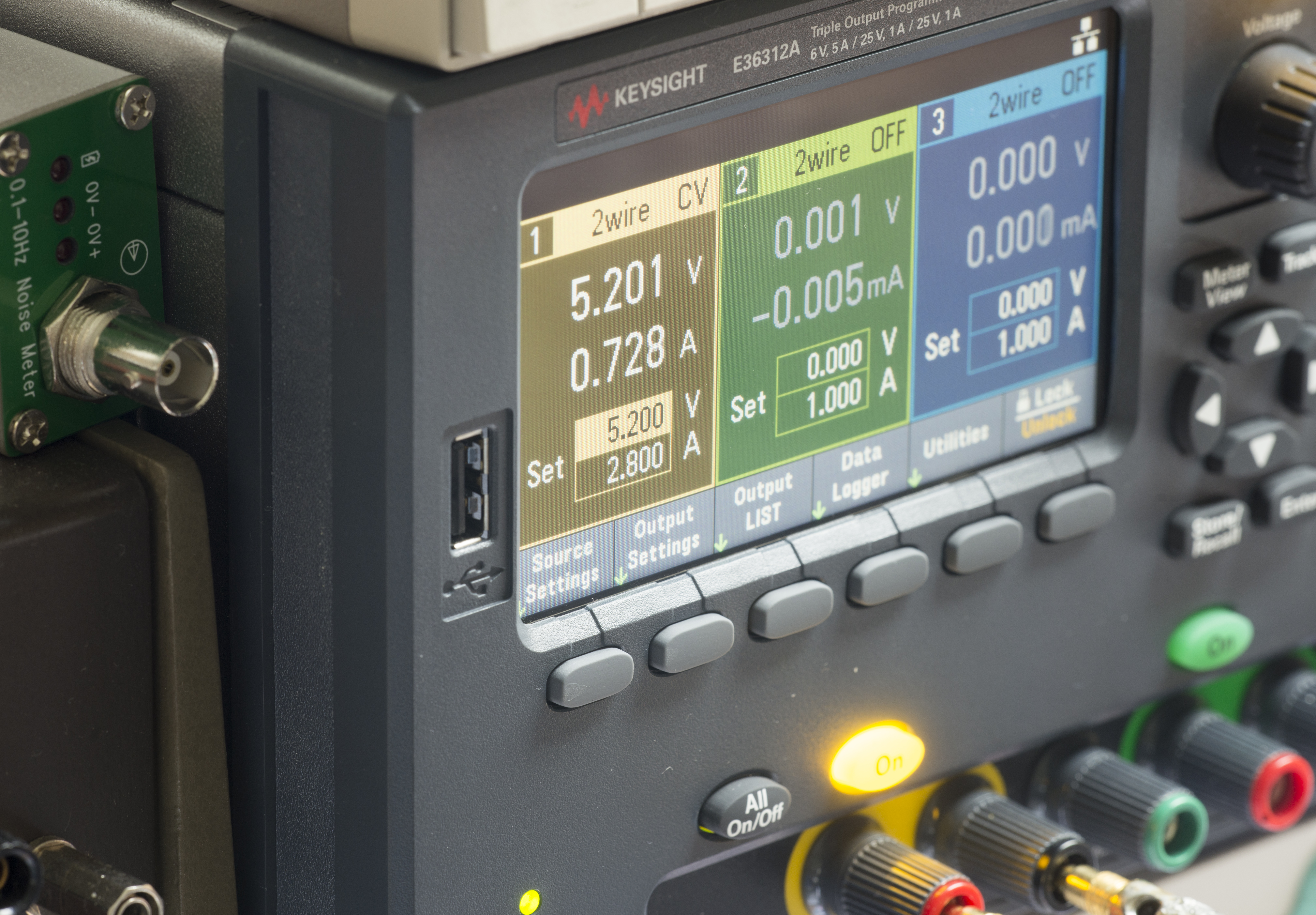
Image 5: Testing digital board operation and power consumption, measured by Keysight E36312A PSU.
Front panel
Analog board
AC power is applied to the AC receptacle J1001 through the fuse F101, line switch S101, and line voltage selection switch S103 to the power transformer T1. The power transformer has a total of 10 secondary windings for the various DC supplies in the instrument.
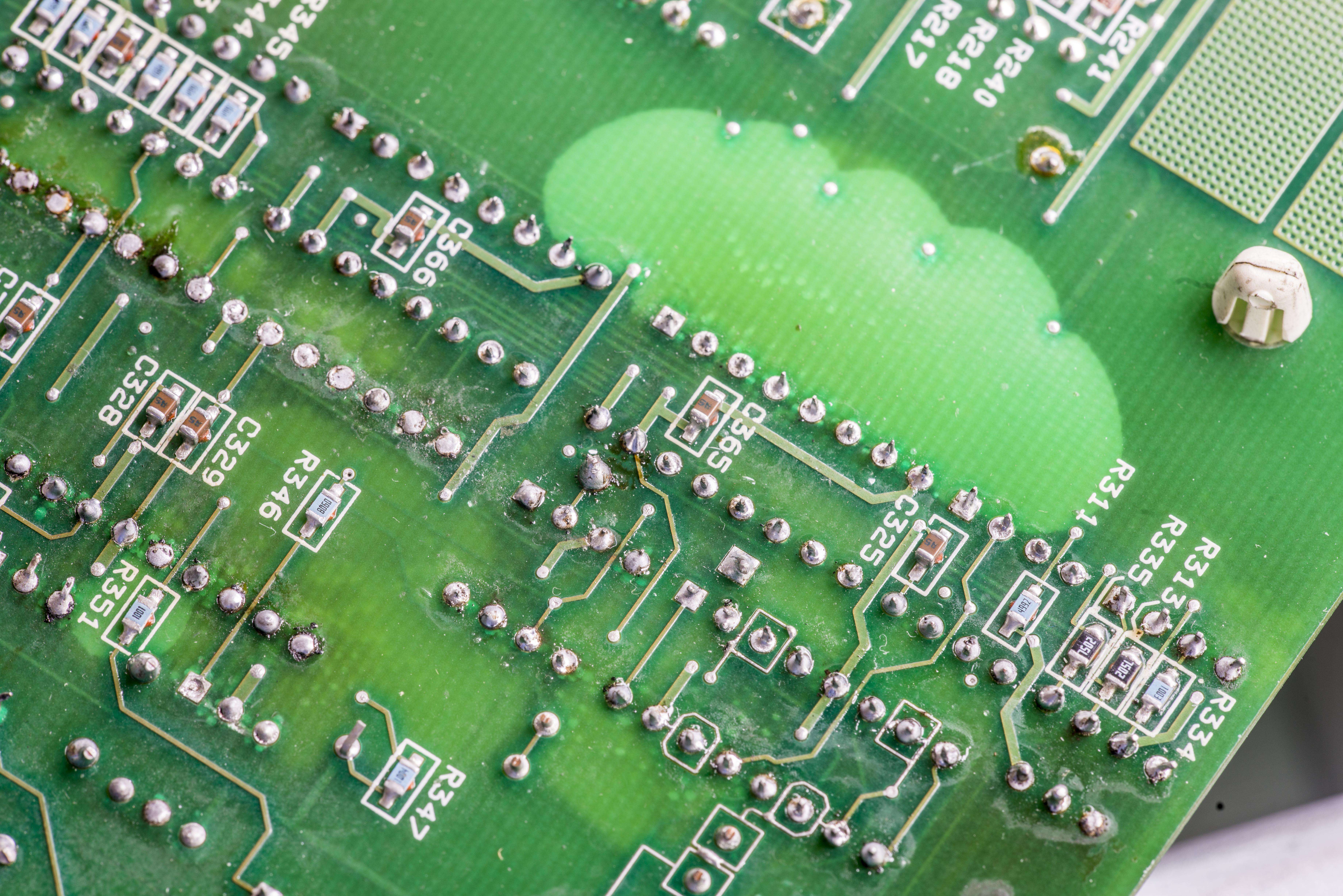
Image 5: A/D Converter and interface bridge
The input preamplifier stage provides the high input impedance necessary for the voltage function, as well as the low input bias current and current- or charge-to-voltage conversion for the amps, ohms, and coulombs functions. The input preamplifier is essentially made up of three sections: the input stage, range/function switching, and the output stage.
The input stage is made up of U405 and associated components. This IC has the required low input bias current, and it also provides the overall gain for the input preamplifier.
The output stage includes Q402-Q413 and associated components. This stage supplies the necessary voltage and current drive capability for the input preamplifier.
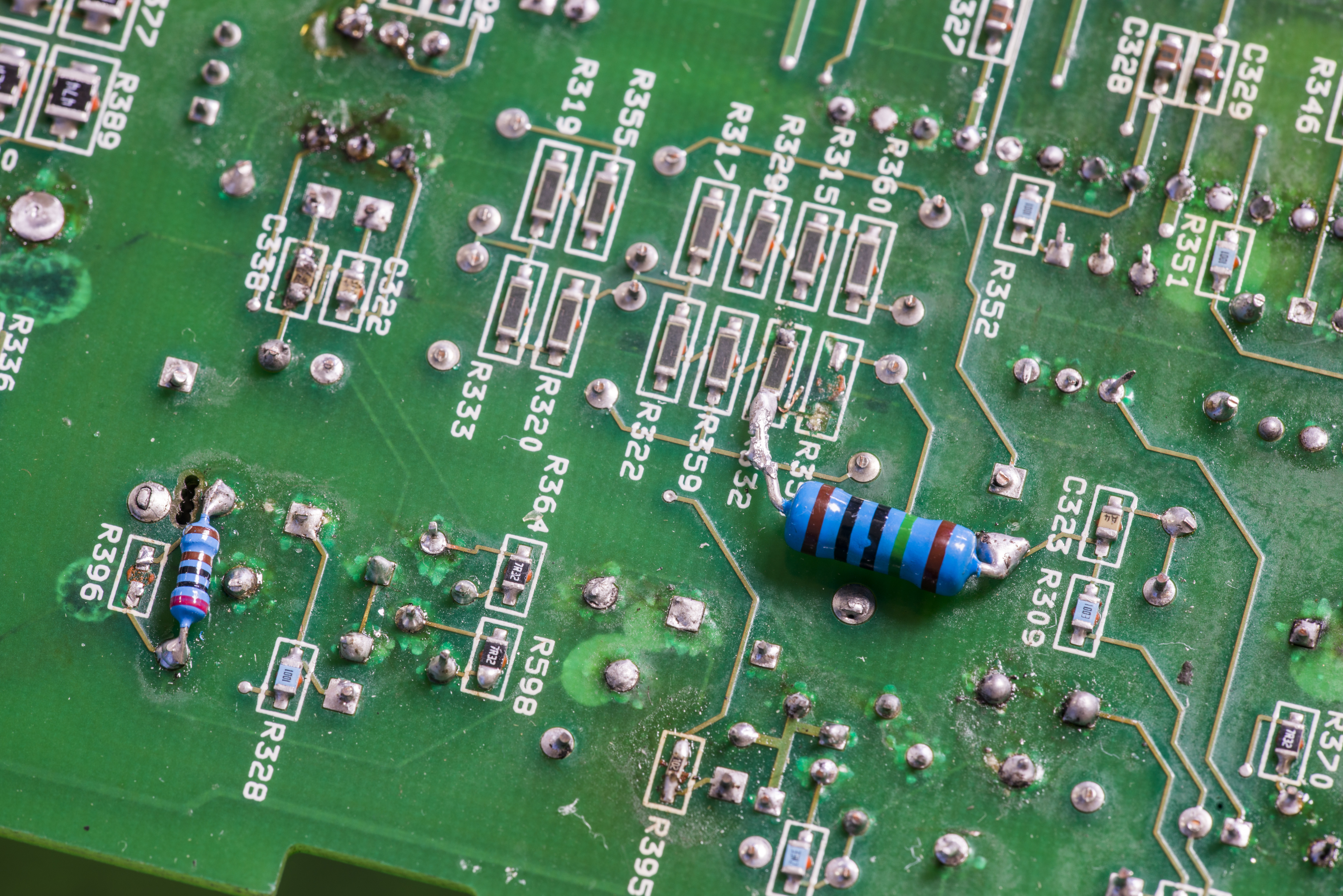
Image 5: A/D Converter and interface bridge
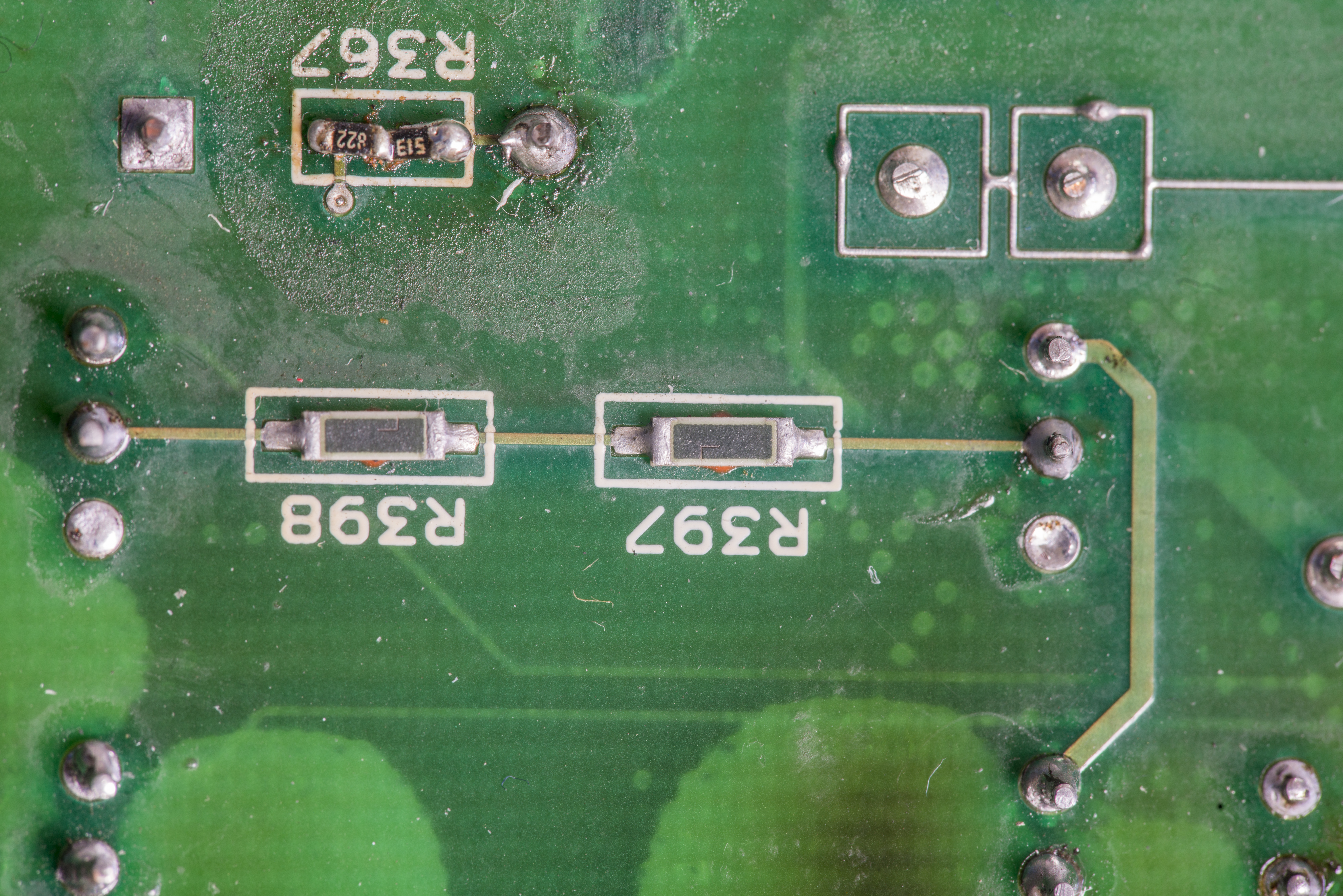
Image 5: High-impedance shielded circuit section, top and bottom view with shields removed.

Image 5: High-impedance shielded circuit section, top and bottom view with shields removed.
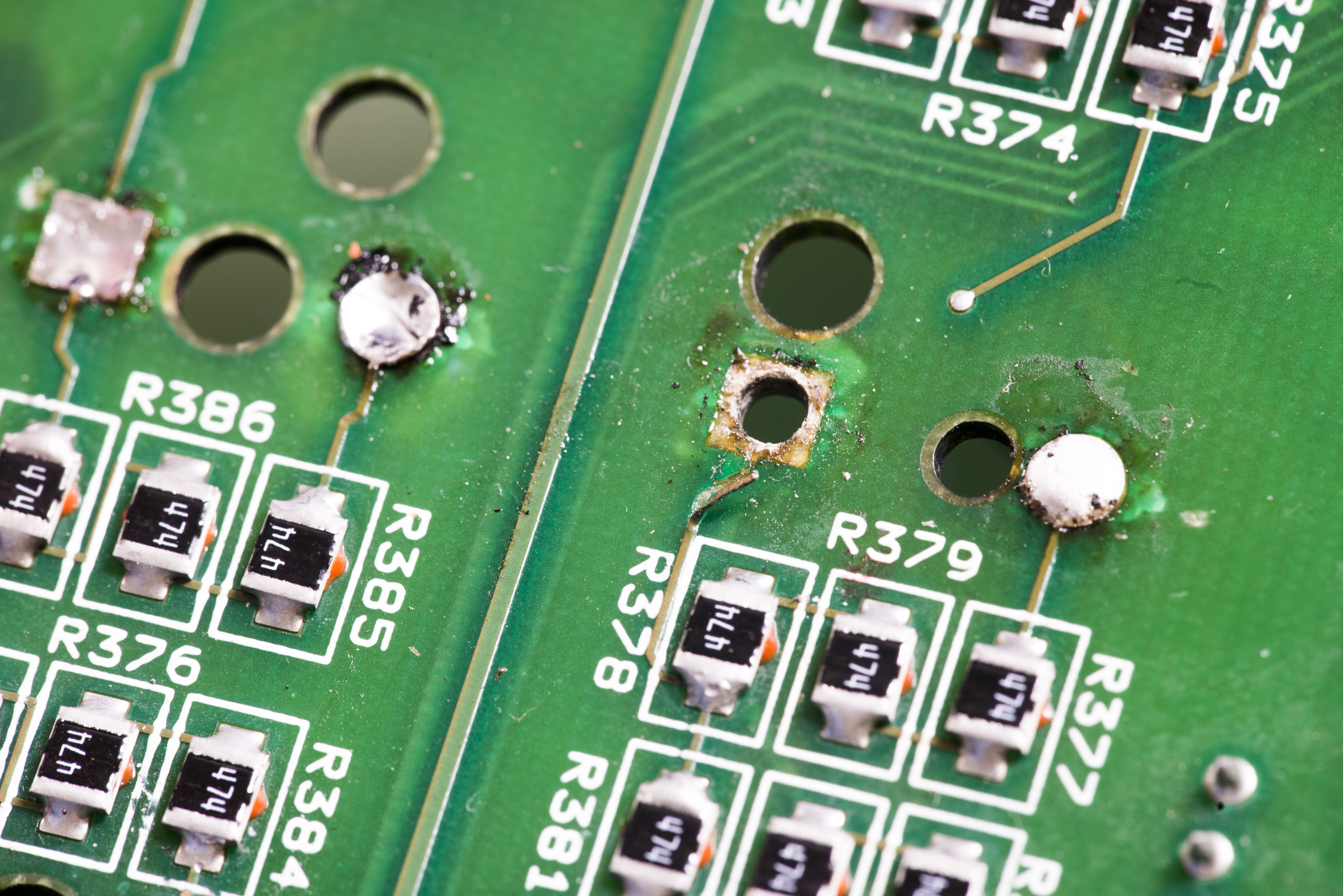
Image 5: High-impedance shielded circuit section, top and bottom view with shields removed.
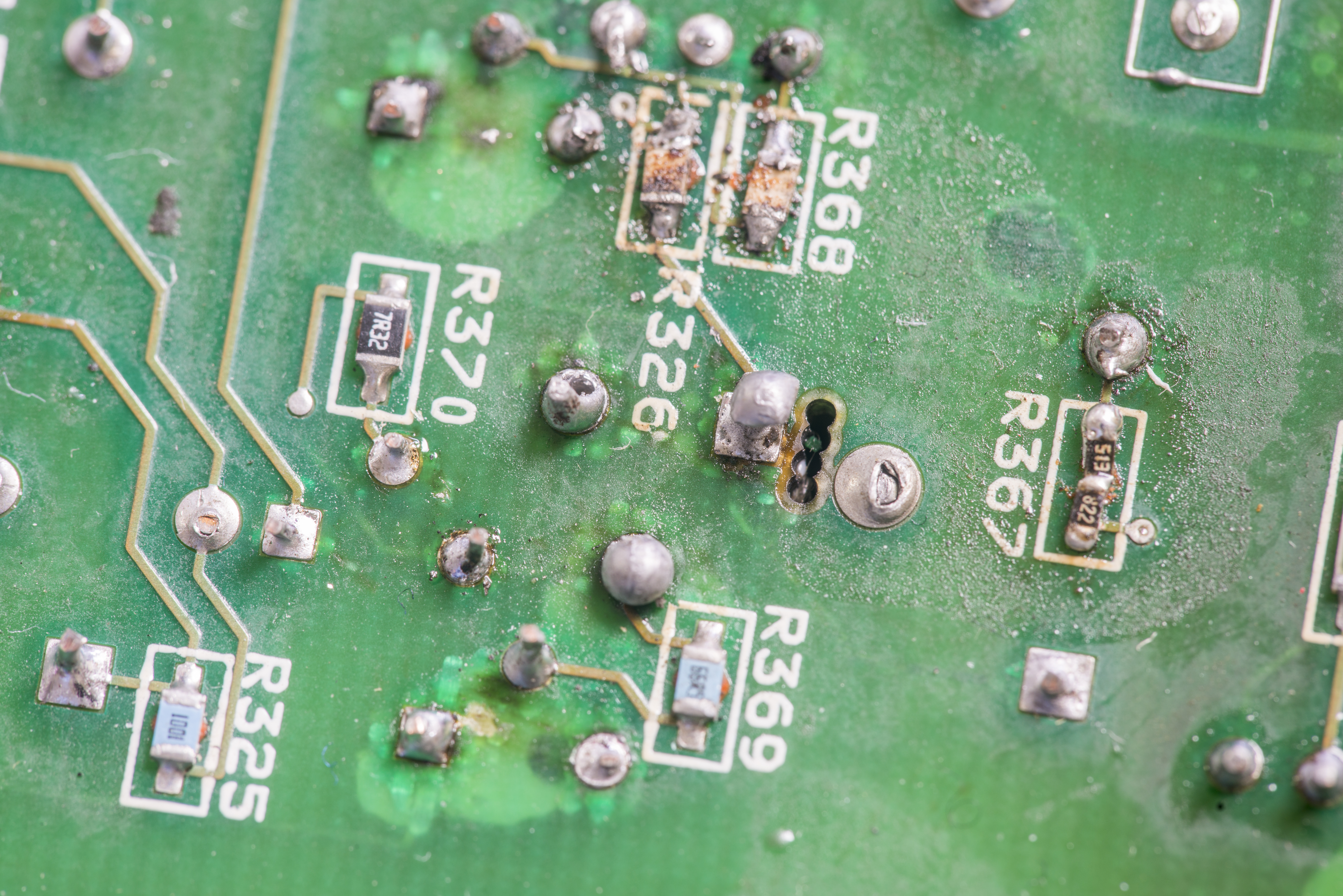
Image 5: High-impedance shielded circuit section, top and bottom view with shields removed.
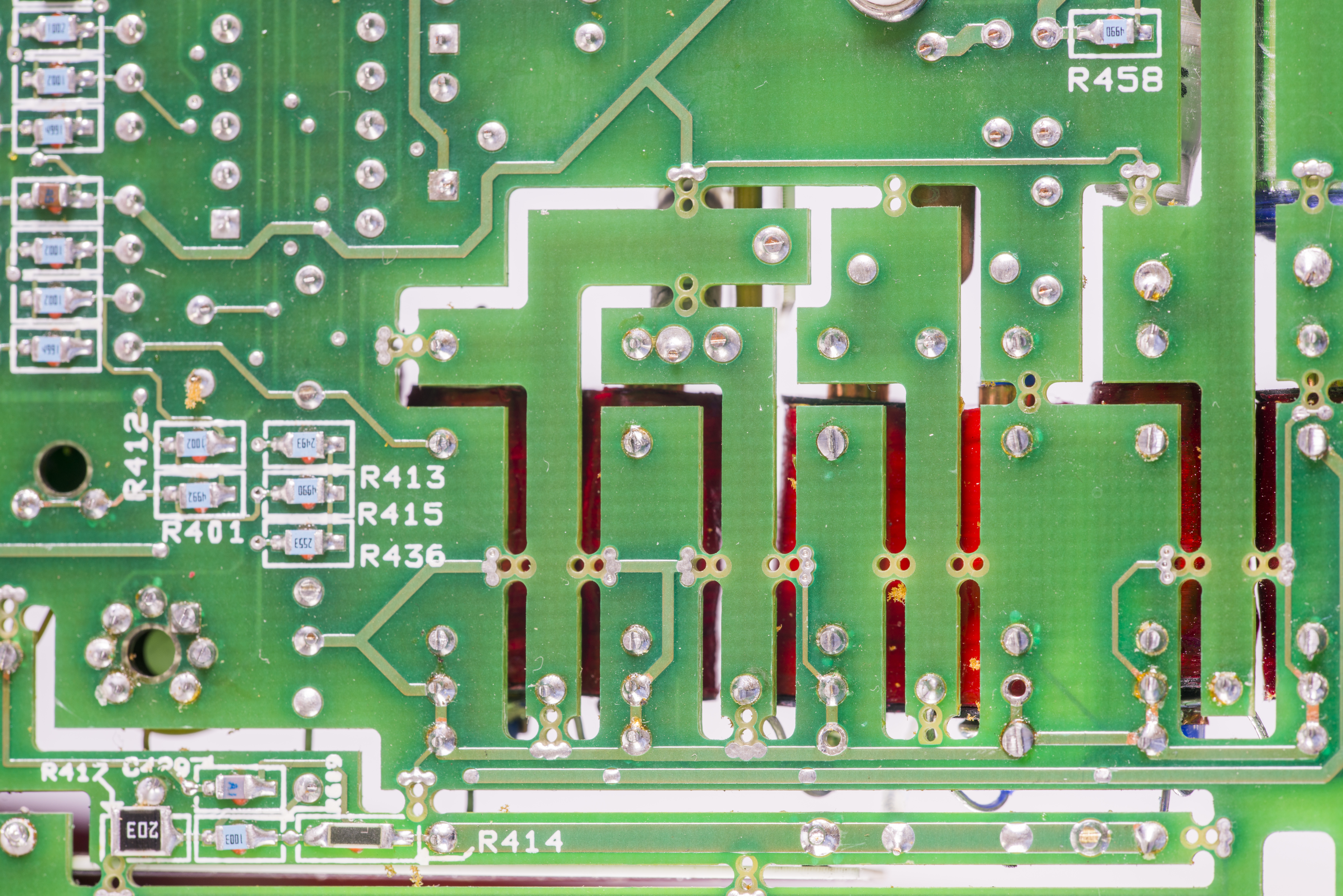
Image 5: High-impedance shielded circuit section, top and bottom view with shields removed.
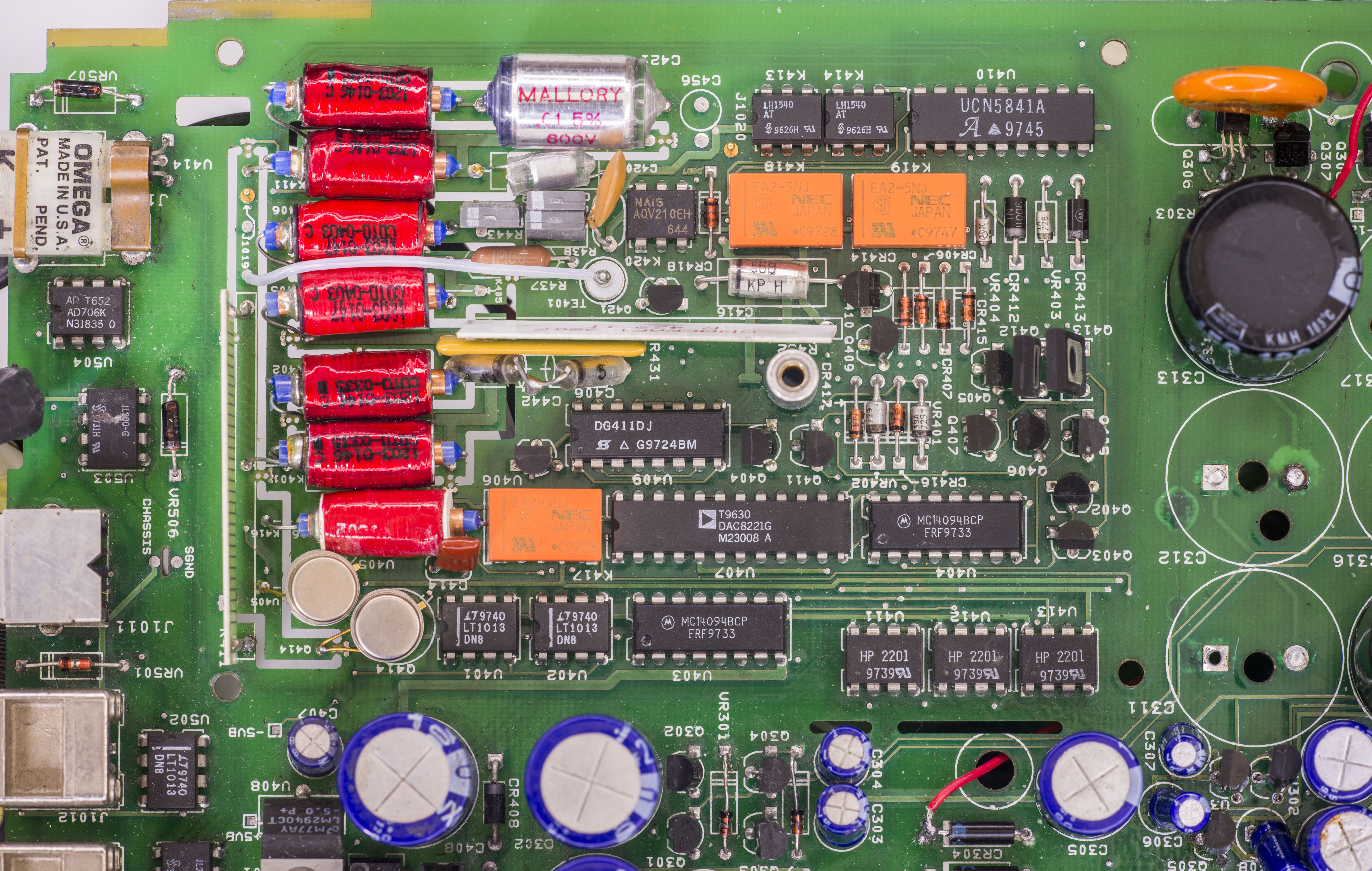
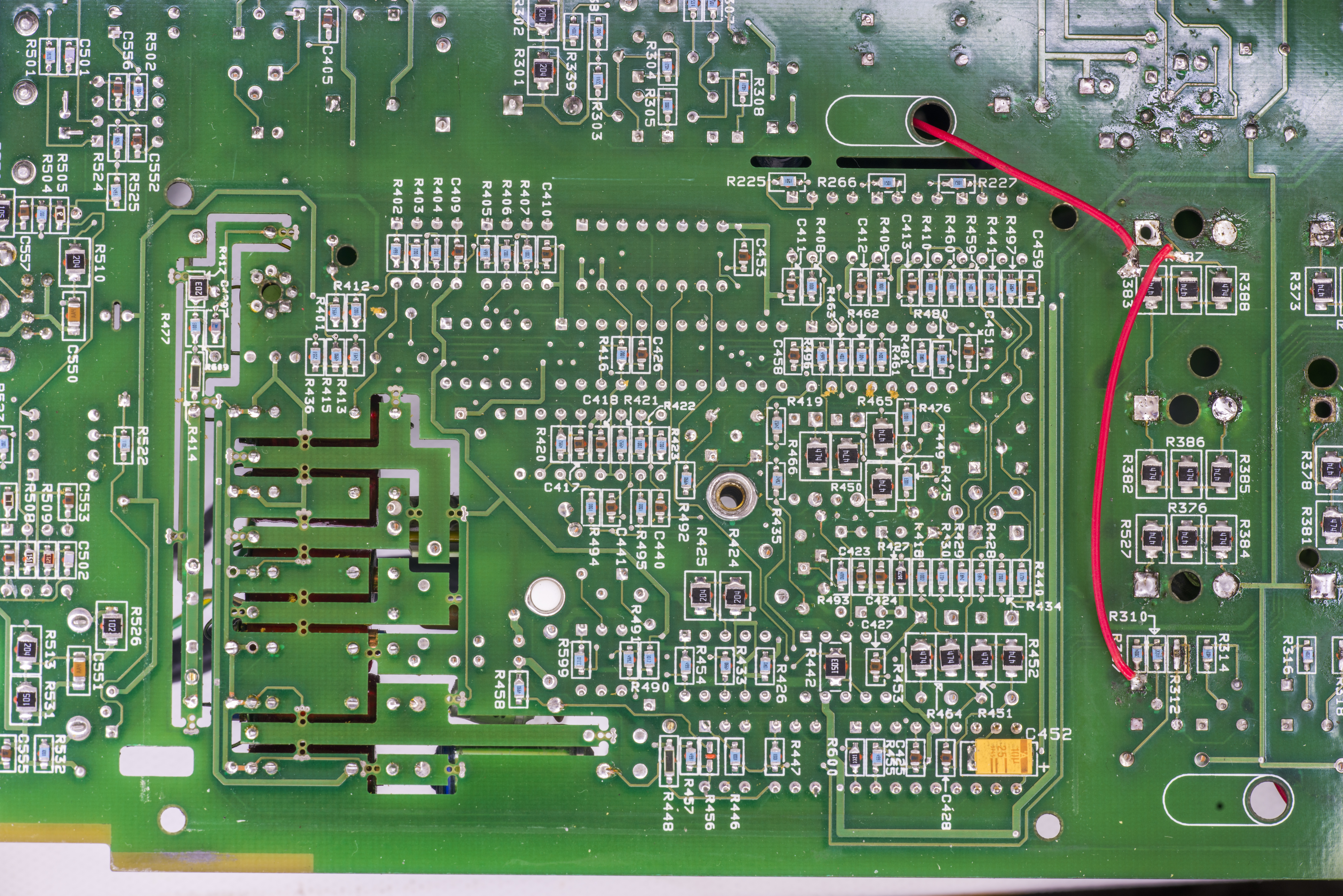
Image 5: High-impedance shielded circuit section, top and bottom view with shields removed.
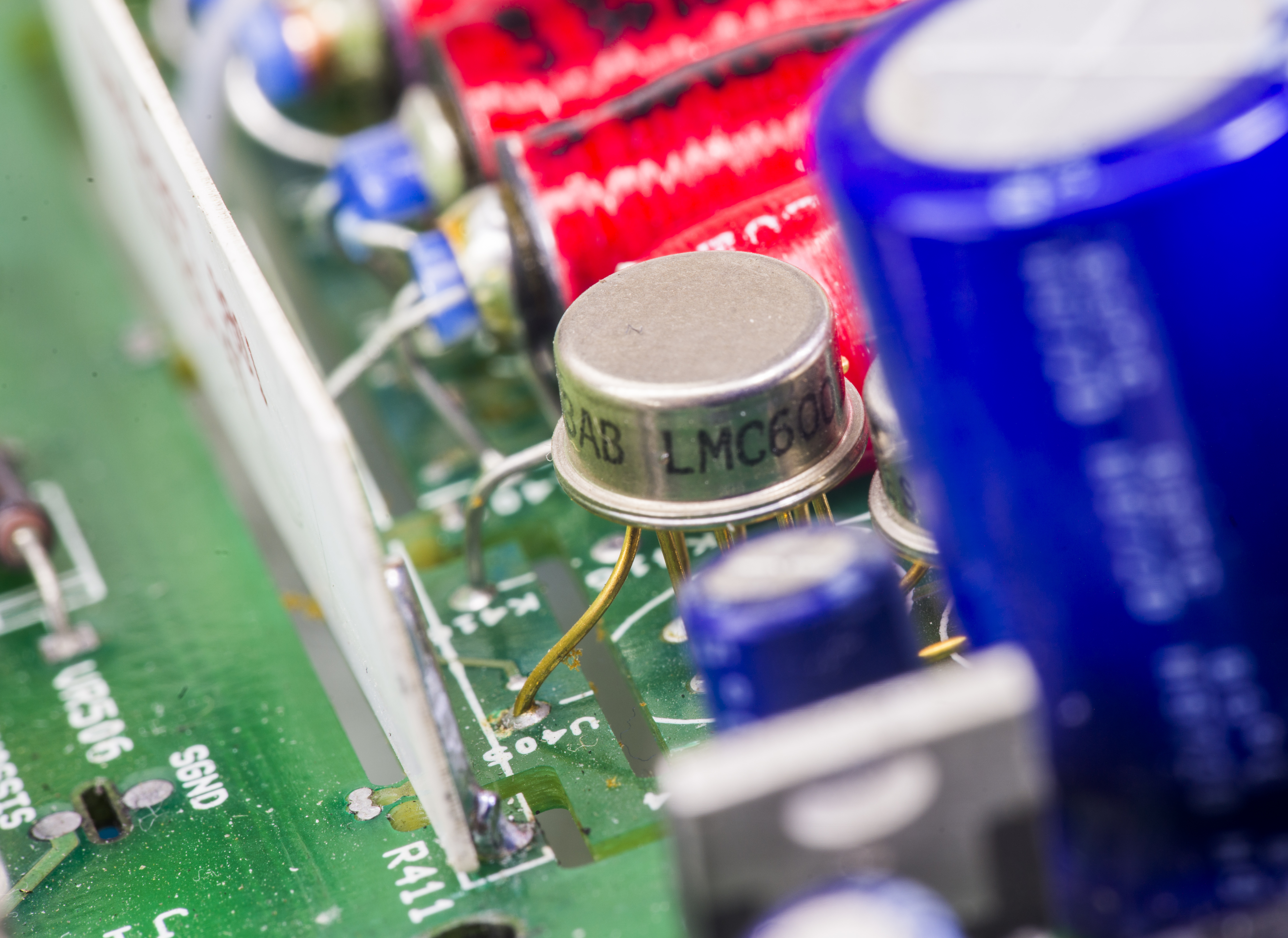
Image 5: Ultra-low input bias current TI LMC6001 opamp in hermetic package.
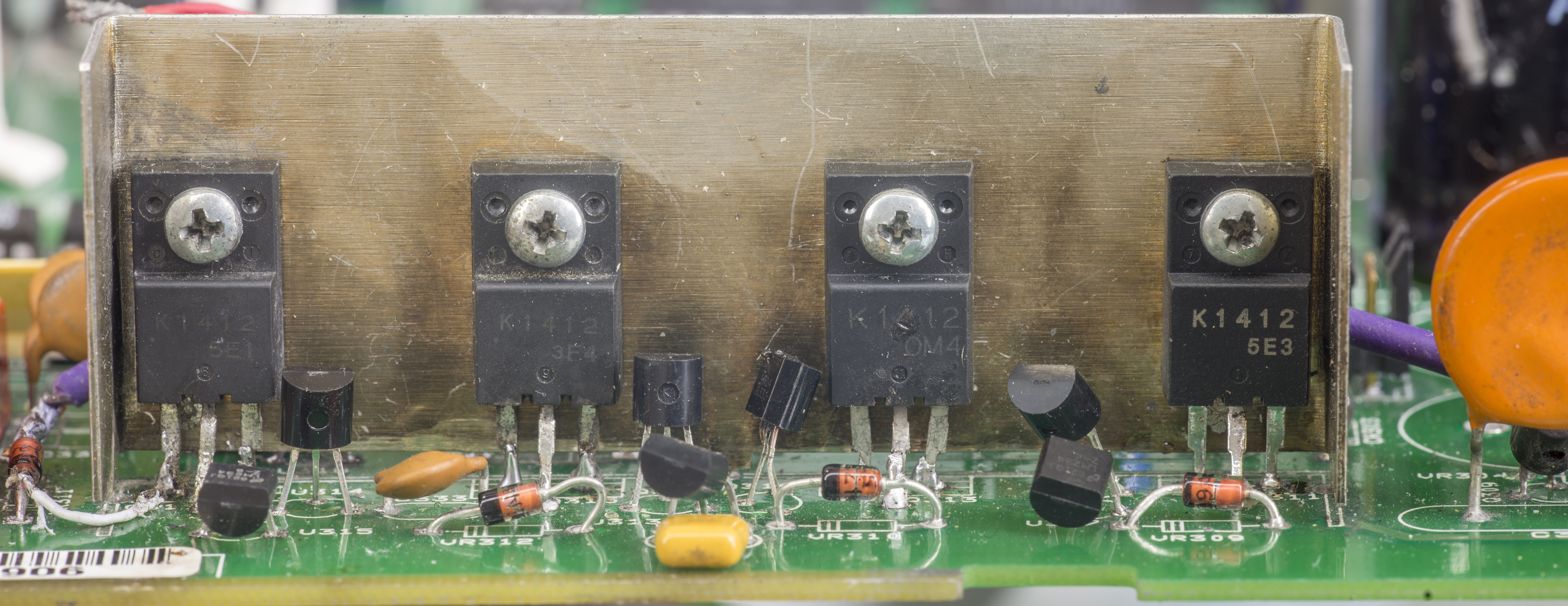
Image 5: A/D Converter and interface bridge

Image 5: A/D Converter and interface bridge

Image 5: A/D Converter and interface bridge
Check power supply voltages
| Section under test | Expected procedure and range | Reference for measurements |
|---|---|---|
| F101 line fuse | Check continuity | Remove to check |
| Line switch | 115V/230V as required. | Line voltage selection switch |
| Line power | Plugged into live receptacle, power on | Check for correct power up sequence |
| Q305, pin 1 | +5V, ±5% | Referenced to Common K (U301 pin 2) |
| U301, pin 1 | +12V, ±5% | Referenced to Common K |
| U302, pin 3 | -12V, ±5% | Referenced to Common K |
| +120VK (VR301 anode) | 110V to 130V | Referenced to Common K |
| -120VK (VR302 cathode) | -110V to -130V | Referenced to Common K |
| +1200VK (VR303 anode) | 1100V to 1300V | Referenced to Common K |
| -1200VK (VR304 cathode) | -1100V to -1300V | Referenced to Common K |
| +5VB (U408 pin 3) | +5V, ±5% | Referenced to Common B (BGND, U408 pin 2) |
| -5VB (Q401 pin 3) | -5V, ±5% | Referenced to Common B |
| +25VS (C461 +) | 22V to 28V | Referenced to Common S (SGND, U207 pin 2) |
| -25VS (C460 -) | -22V to -28V | Referenced to Common S |
| +5VS (U207 pin 3) | +5V, ±5% | Referenced to Common S |
| +220VS (C401 +) | 200V to 240V | Referenced to Common S |
| -220VS (C403 -) | -200V to -240V | Referenced to Common S |
| +15VS (U206 pin 3) | +15V, ±5% | Referenced to Common S |
| -15VS (U205 pin 3) | -15V, ±5% | Referenced to Common S |
Test results
| Supply | Rectifier | Filter | Regulator | Measured | Result |
|---|---|---|---|---|---|
| +5VK | CR306 | C305, C308 | Q305 | NOK | |
| +12VK | CR307 | C307, C309 | U301 | NOK | |
| -12VK | CR307 | C306, C310 | U302 | NOK | |
| +120VK | CR301 | C302 | N/A | NOK | |
| -120VK | CR301 | C301 | N/A | NOK | |
| +1200VK | CR304 | C311-C313 | N/A | NOK | |
| -1200VK | CR305 | C315-C317 | N/A | NOK | |
| +5VB | CR403 | C407, C408 | U408 | NOK | |
| -5VB | CR403 | C422 | Q401 | NOK | |
| +25VS | CR402 | C404, C461 | N/A | NOK | |
| -25VS | CR402 | C402, C460 | N/A | NOK | |
| +5VS | CR201 | C201-C203 | U207 | NOK | |
| +220VS | CR401 | C401 | N/A | NOK | |
| -220VS | CR401 | C403 | N/A | NOK | |
| +15VS | CR202 | C211, C217 | U206 | NOK | |
| -15VS | CR202 | C209, C218 | U205 | NOK |
Conclusion
Cost involved in this project:
| Item | Cost | Shipping | Supplier |
|---|---|---|---|
| Dead Keithley 6517A | N/A | N/A | Customer |
| Dead Keithley 6517 for donor parts | $1000 | ?0$ | eBay |
| Transformer Keithley TR | $600 | N/A | Tektronix, replaced by customer |
| 30 pcs CHV2010-FX-1005ELFCT-ND Resistors 10 MΩ 2010 size | $10 | 0$ | Digikey USA |
Total repair cost in parts as for today: $1700 USD. This instrument was repaired by complete analog board replacement from another donor 6517A instrument with broken digital board.
| Date | Activity | Time spent |
|---|---|---|
| 2/6/2018 | Received unit, initial teardown, photos | 3 hours |
| 3/5/2018 | Analog board replacement | 3 hours |
Discussion about this article and related stuff is welcome in comment section or at our own IRC chat server: irc.xdevs.com (standard port 6667, channel: #xDevs.com). Web-interface for access mirrored on this page.
Projects like this are born from passion and a desire to share how things work. Education is the foundation of a healthy society - especially important in today's volatile world. xDevs began as a personal project notepad in Kherson, Ukraine back in 2008 and has grown with support of passionate readers just like you. There are no (and never will be) any ads, sponsors or shareholders behind xDevs.com, just a commitment to inspire and help learning. If you are in a position to help others like us, please consider supporting xDevs.com’s home-country Ukraine in its defense of freedom to speak, freedom to live in peace and freedom to choose their way. You can use official site to support Ukraine – United24 or Help99. Every cent counts.
Modified: April 25, 2026, 11:19 p.m.