Contents
- Intro
- Manuals
- Teardown
- Firmware
- Repair worklog
- Calibration
- Performance test
- Stability test
- Display modification
- Summary and conclusion
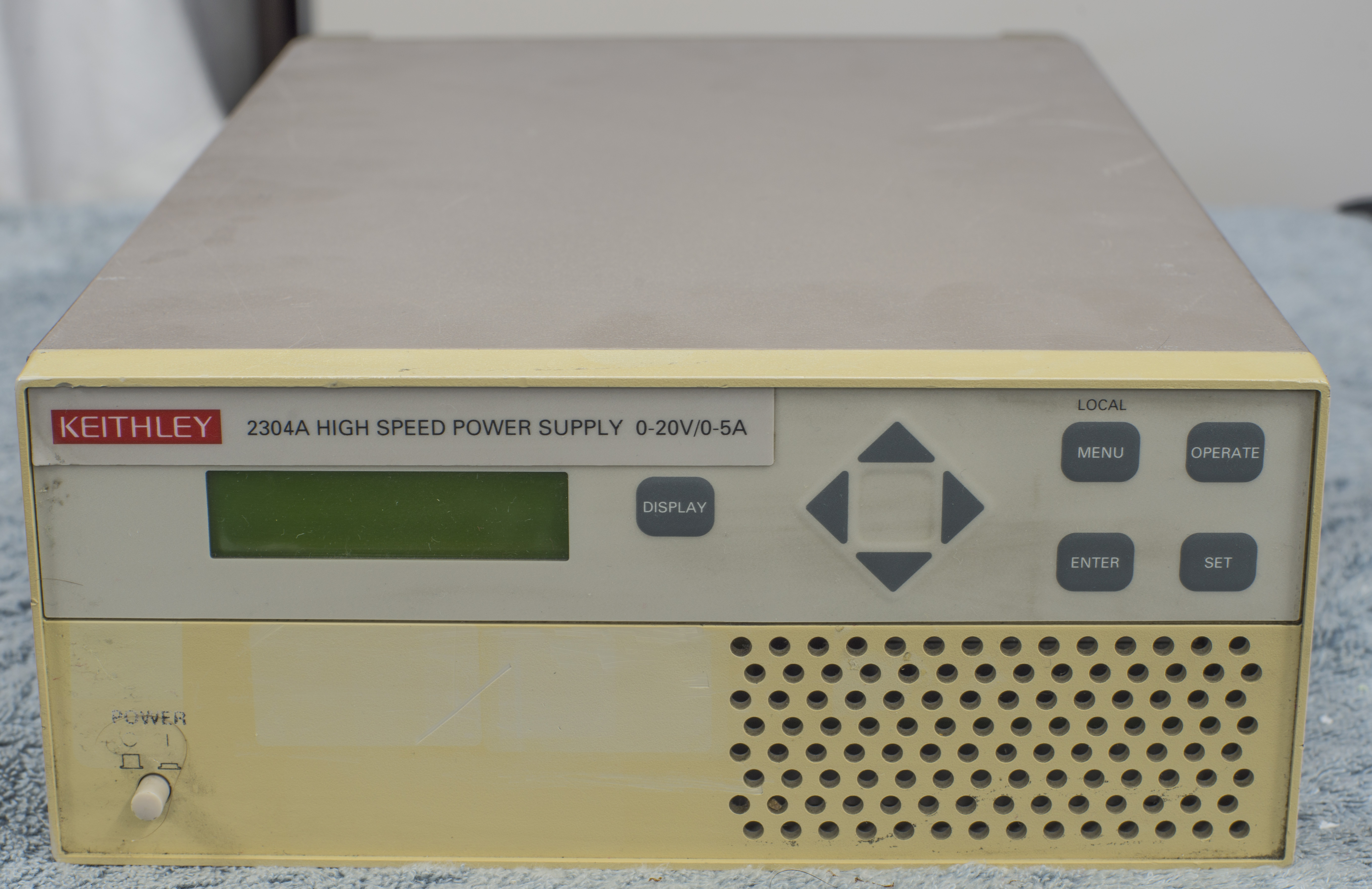
Intro
The Model 2304A PSU able to control both voltage and current, designed for automated testing of portable, battery-operated devices. They have high speed in the name because of specific design for handling fast substantial loads, which can cause large voltage drops on for very short time intervals on regular PSUs.
This family of power supplies also can sink current and, thus, take on the characteristics of a discharged, rechargeable battery for testing various chargers and charger-control circuitry. 2304A able to act as non-programmable DC current electronic load in this respect.
Because of their design, operating with large load change is possible, with recovering to within 100 mV of the original voltage in very short time, 40µs or less.
Key features from data-sheet:
- Optimized for battery-powered device testing
- Ultra-fast transient response to load changes
- 5A continuous output
- Pulse peak, average, and baseline current measurements
- 100nA DC current sensitivity
- High Current 3A Sinking Capacity
Tektronix still have Model 2304A listed on their site shop for MSRP 2880 $USD, even though they have newer Model 2281S with similar target application.
Manuals
Model 2303,2304A High Speed Power Supplies Datasheet
Model 2303/2303PJ specifications, Rev.A 7/24/2001
Model 2303 Service Manual, Rev.C, November 1999
Model 2303 User’s Manual, Rev.F, August 2003
Model 2304A Quick Start User Guide
Model 2304A User’s Manual, Rev.B, March 1999
Model 2304A Calibration Manual, Rev.A, July 1999
Model 2304A High-Speed Precision Power Supply specification, Rev.A, 8/21/2001
Let’s take a brief look on comparison of modern Model 2281S and 2304A.
| Description | Model 2281S | Model 2304A | Units and conditions |
|---|---|---|---|
| Maximum rated power | 120 | 100 | W, +35°C ambient |
| Output voltage | 0.000 to +20.000 | 0.000 to +20.000 | VDC |
| Output voltage (Enhanced) | 0.000 to +15.000 | VDC | |
| Output accuracy | ±0.02% + 3mV | ±0.05% + 10mV | VDC |
| Voltage programming resolution | 1 | 5 | mVDC |
| Voltage readback accuracy | ±0.02% + 2mV | ±0.05% + 10mV | VDC |
| Voltage readback resolution | 0.1 | 1 | mVDC |
| Output voltage settling time | <50µs to ±15mV setting | 5ms to within stated accuracy | s |
| Voltage Load regulation | ± 0.01% + 2mV | ± 0.01% + 2mV | VDC |
| Voltage Line regulation | ± 0.01% + 1mV | ± 0.5 | mVDC |
| Voltage Stability | 0.01% + 0.5mV | VDC | |
| Output Current | 0.000 to 6.000 | 0.000 to 5.000 | ADC |
| Compliance Accuracy | ±(0.16% + 5mA) | ADC | |
| Programmed compliance resolution | 1.25 | mADC | |
| Readback Accuracy (10A/5A range) | ±(0.05% + 0.25mA) | ±(0.2% + 1mA) | ADC |
| Readback Accuracy (10mA/5mA range) | ±(0.04% + 10µA) | ±(0.2% + 1µA) | ADC |
| Current readback Resolution (5A) | 10µ | 100µ | ADC |
| Current readback resolution (5mA) | 10 nA | 100 nA | nADC |
| Current Sink Capacity | 0.000 to 1.02 | 0.000 to 3.000 | ADC |
| Current Sink Capacity (Enhanced) | 0.000 to 1.000 | ADC | |
| Current Load Regulation | ± 0.01% + 0.25mA | ± 0.01% + 1mA | ADC |
| Current Line Regulation | ± 0.01% + 0.25mA | ± 0.5 | mADC |
| Current Stability | 0.01% + 50µ | ADC | |
| DVM Input Voltage Range | 0 to +20 | VDC | |
| DVM Input Impedance | 1010 typical | Ω | |
| DVM Maximum Voltage (to Output Low | -3 to +22 | VDC | |
| DVM Reading Accuracy | ±0.02% + 2mV | ±0.05% + 10mV | VDC |
| Reading Resolution | 5½-digit | 1 | mVDC |
| Isolation (Low-Earth) | 240 Maximum | 22 Maximum | VDC |
| Programming | LAN, USB host, USB device, IEEE-488.2 (SCPI) | IEEE-488.2 (SCPI) | |
| Output connector type | Front banana ports, rear 6-position terminal | Rear 8-position terminal block | |
| Input Power | 100-240 , 50-60Hz | VAC | |
| MSRP (February 2016) | $2990 | $2880 | USD |
Table 1. Specifications of Model 2304A and 2281S (1 year, +23°C)
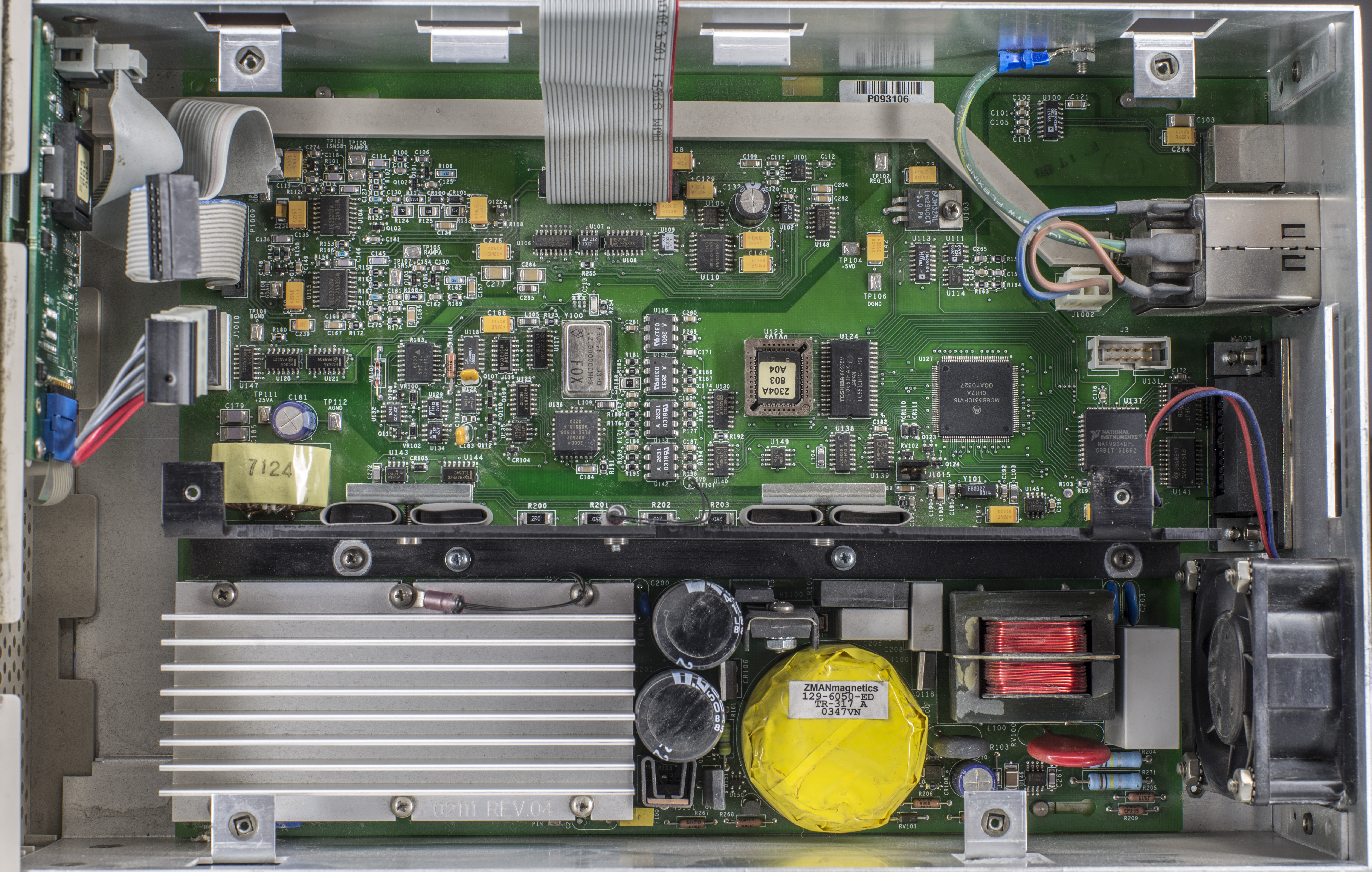
Teardown
This is rather complex power supply, with two large boards, featuring digital controller and analog power module.
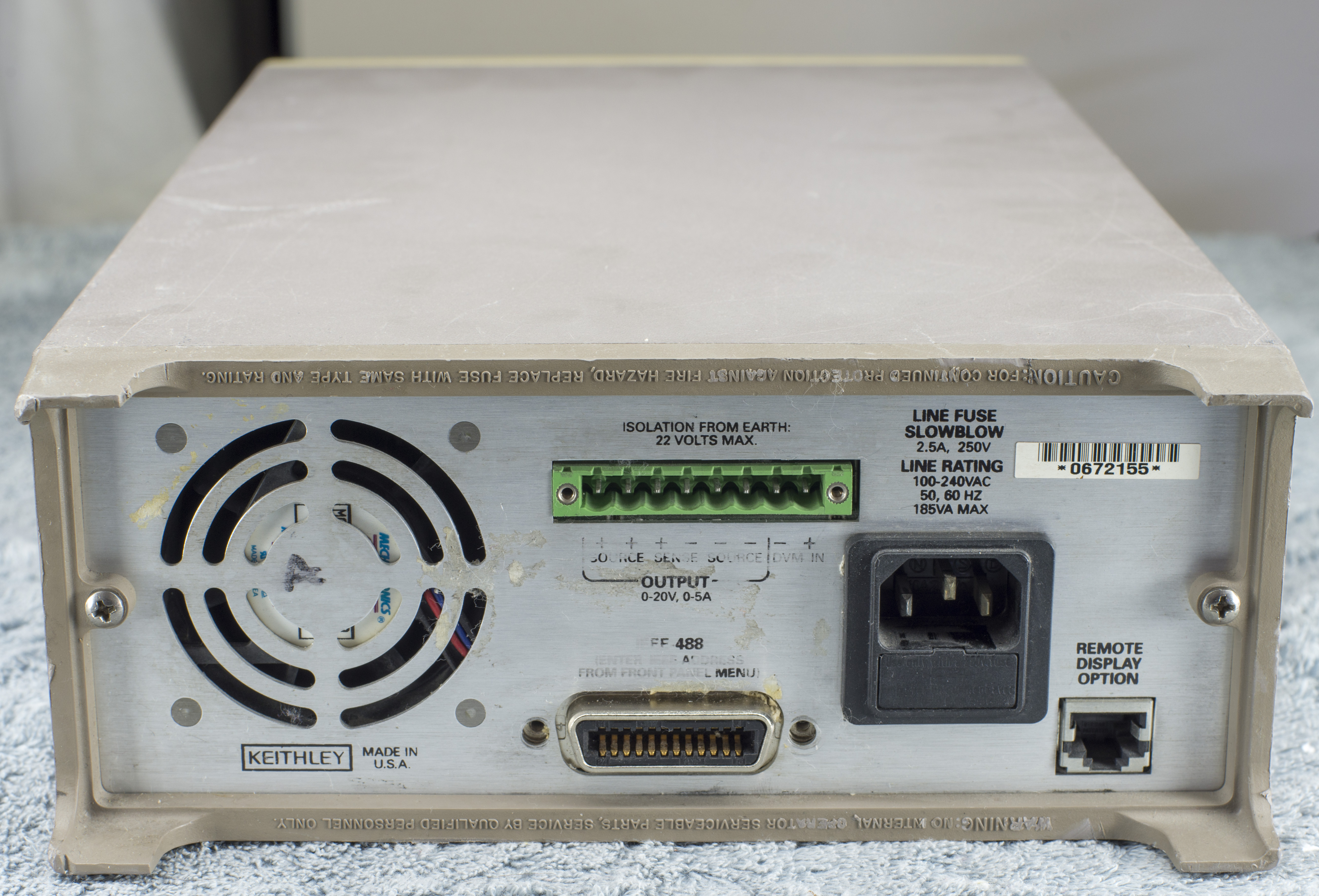
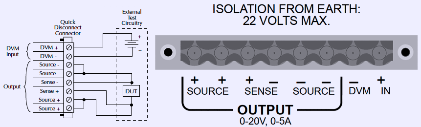
Output is available only at rear terminal block connector with 8 positions with 5.08mm pitch. Mating receptacle can be bought from retailers, such as Digikey 609-4225-ND. There are many different type connectors, with various wire connection locks, so you can choose suitable for your needs with ease.
Mains supply
Digital board – 2304-102
Digital domain is fairly similar to Keithley 2000, with Motorola MC68331CPV16 processor, Toshiba TC551001CF 70ns SRAM chip and AM29F002 firmware ROM in PLCC socket. It’s interface to analog world is isolated via array of optocouplers.
Integration multi-slope ADC is located right behind them, made by using of U118 SD5400CY matched quad MOSFET switch, few op-amps (AD744, OP177, LT1124) and infamous TF-245 resistor network. Main reference is zener diode VR101 (?). Integration counts are processed by 2000-802A02 ASIC, same one used in Keithley 2000/2400 series instruments. This is common approach to reuse existing building blocks in multiple designs to save overall design cost and time on debug.
There are few UC3824 High-speed PWM controllers located on top right edge of the digital board.
Calibration data is stored in U145 EEPROM, simple 24LC16 I2C chip.
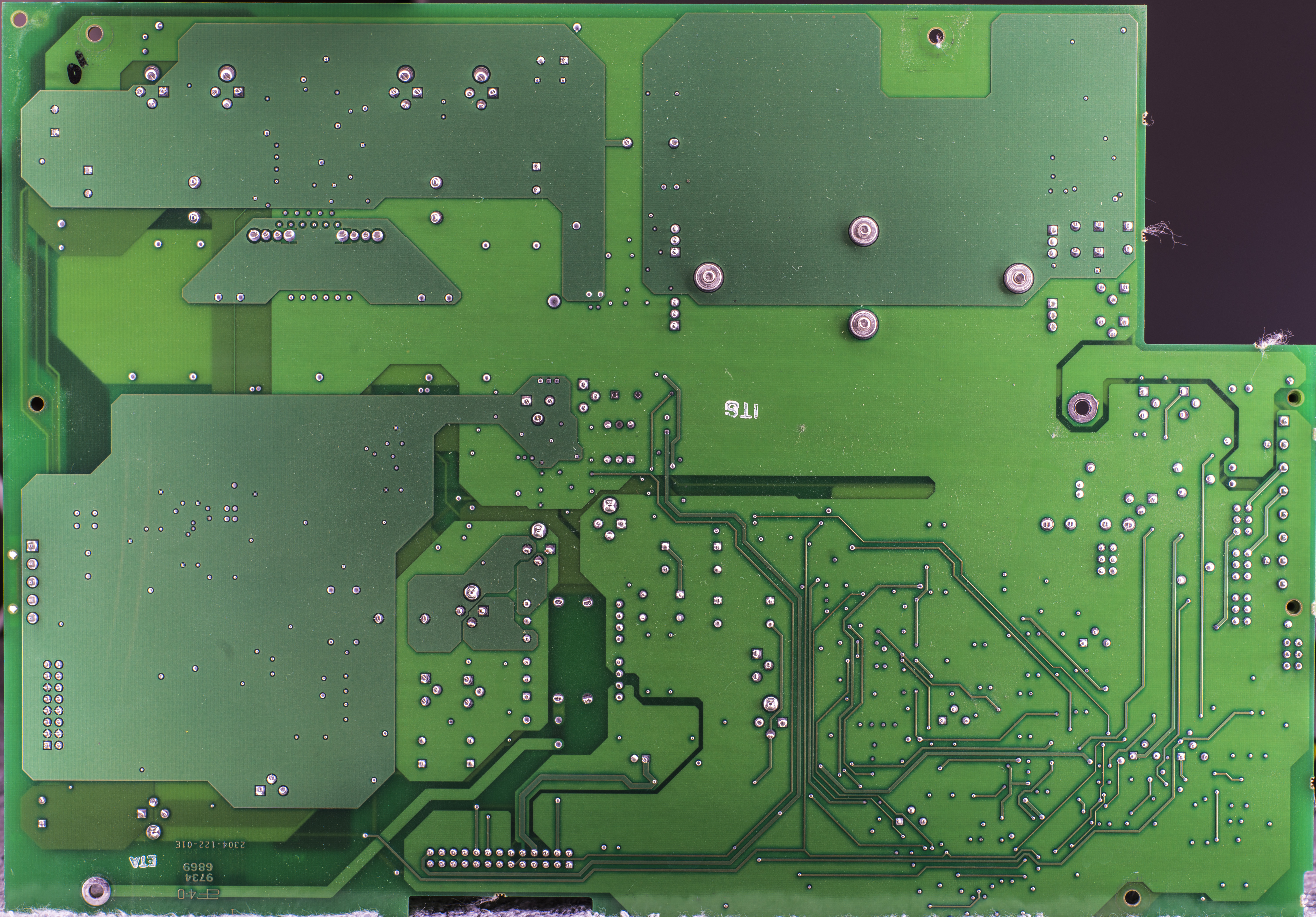
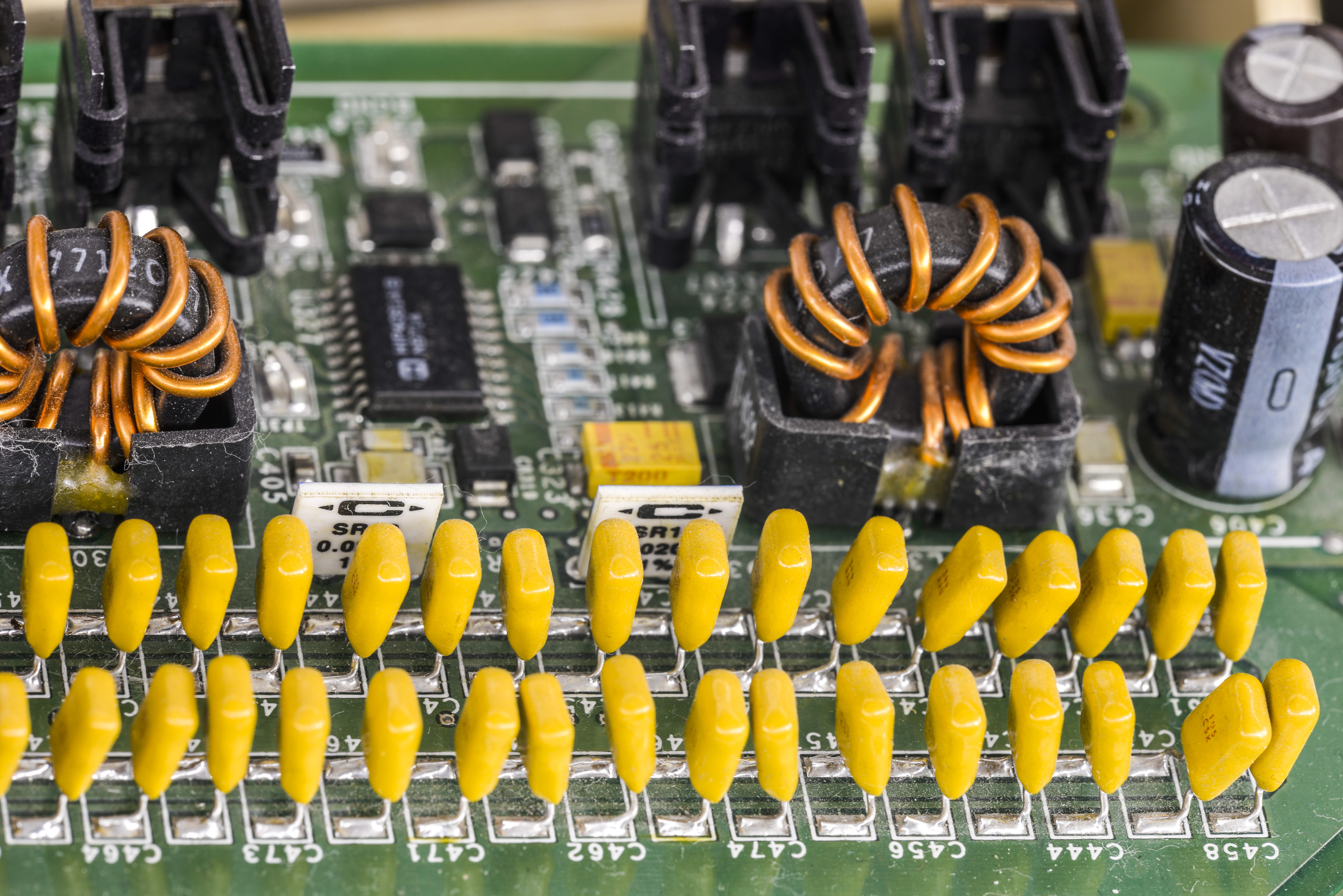
Analog board – 2304-122, Rev.E
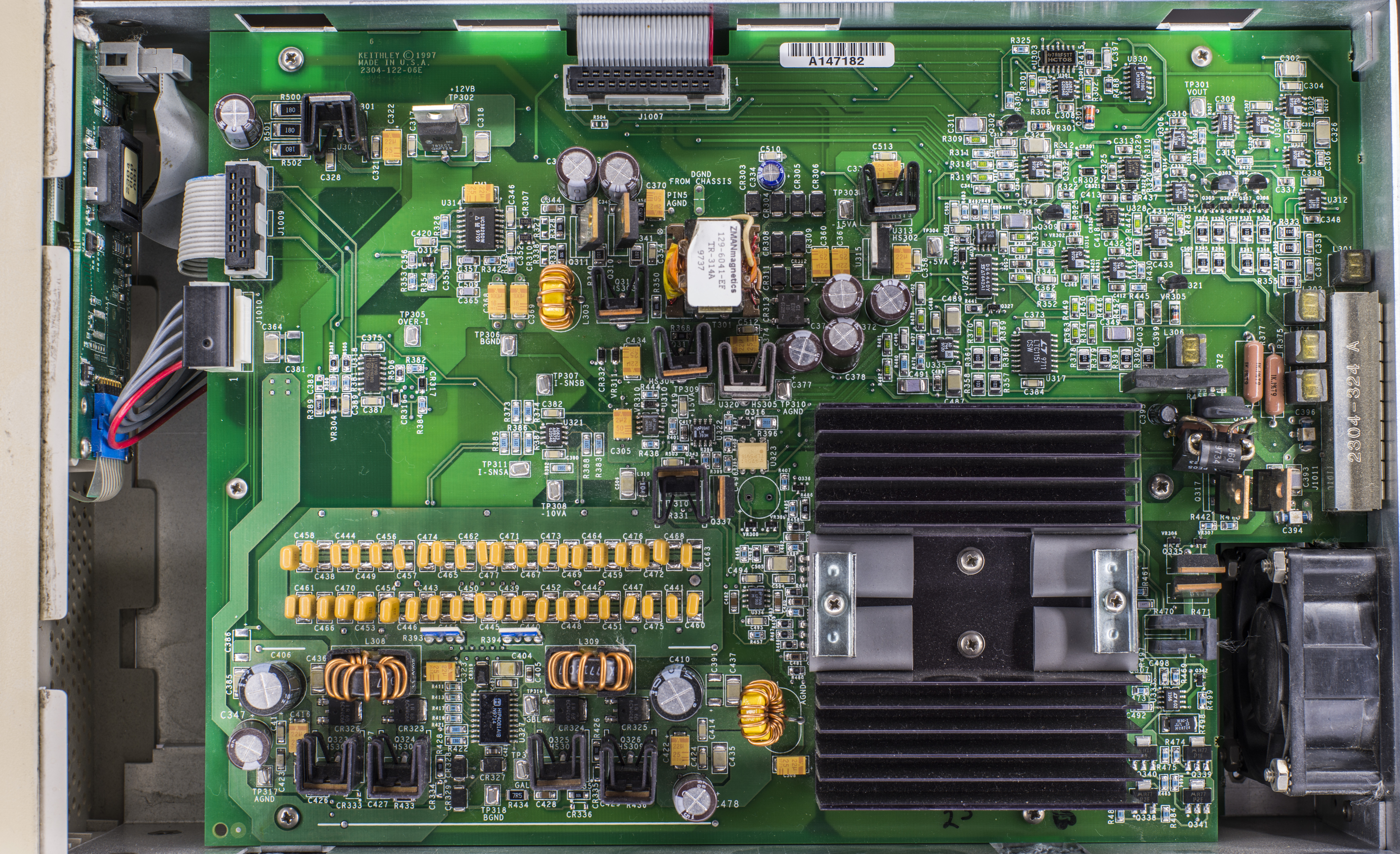
Much more going on this PCBA, located just above the digital board and PSU.
We can see here UC3825 PWM controller again, ZMANmagnetics custom made transformer with Keithley’s part number TR-314A, array of 100V electrolytic capacitors. To the right of this converter many analog parts are located, with array of opamps, AD744, AD823, LTC1151, switch DG444DY, LF353.
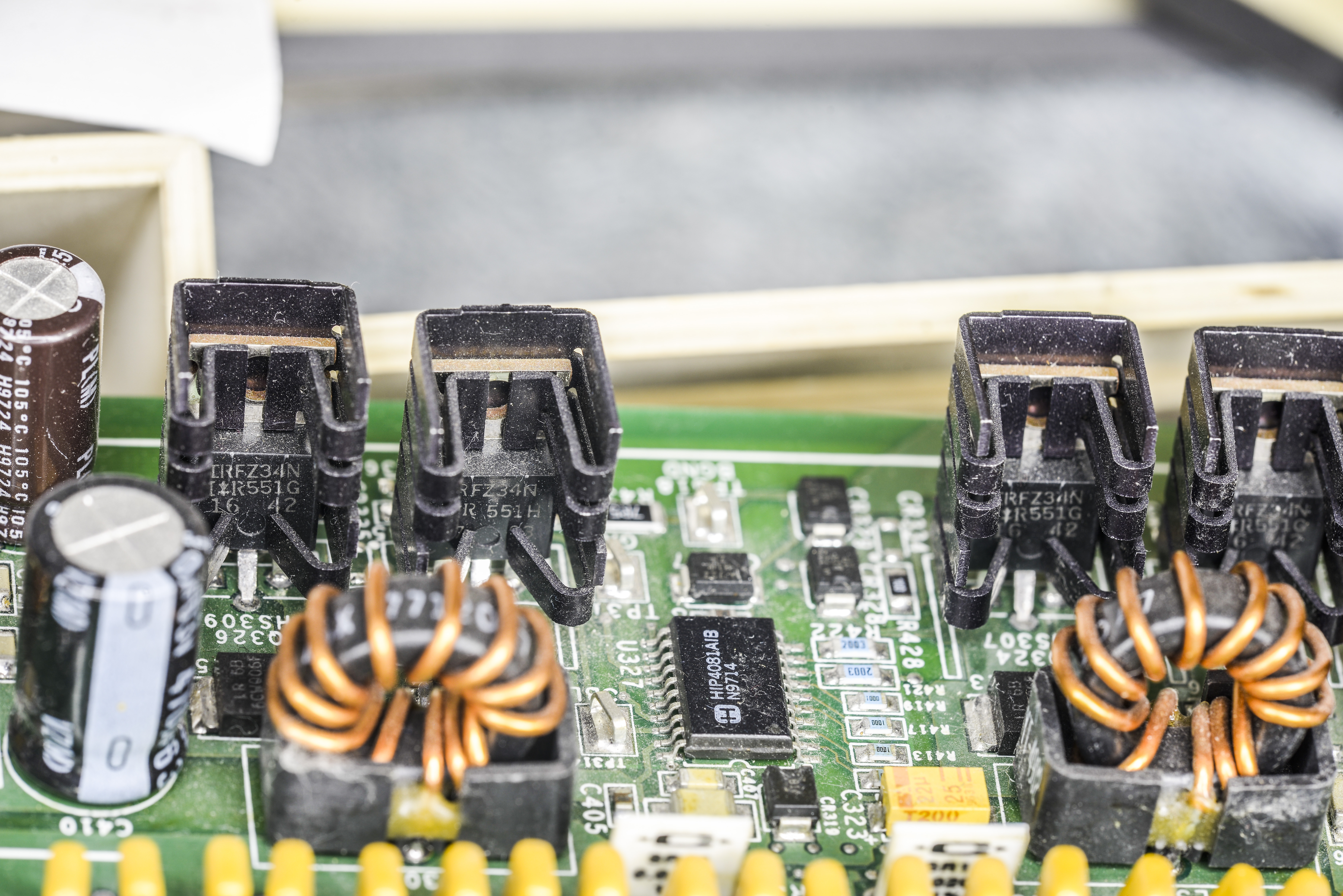
Main power converter is likely one located on bottom part of the board, Intersil HIP4081AIB. This is 80V/2.5A Peak, High Frequency Full Bridge FET Driver, capable of operation at 1MHz. Large array of ceramic capacitors placed just above it.

Bridge protection for shunts and some analog circuits.
HIP DC-DC converter with IRFZ34N MOSFETs around.
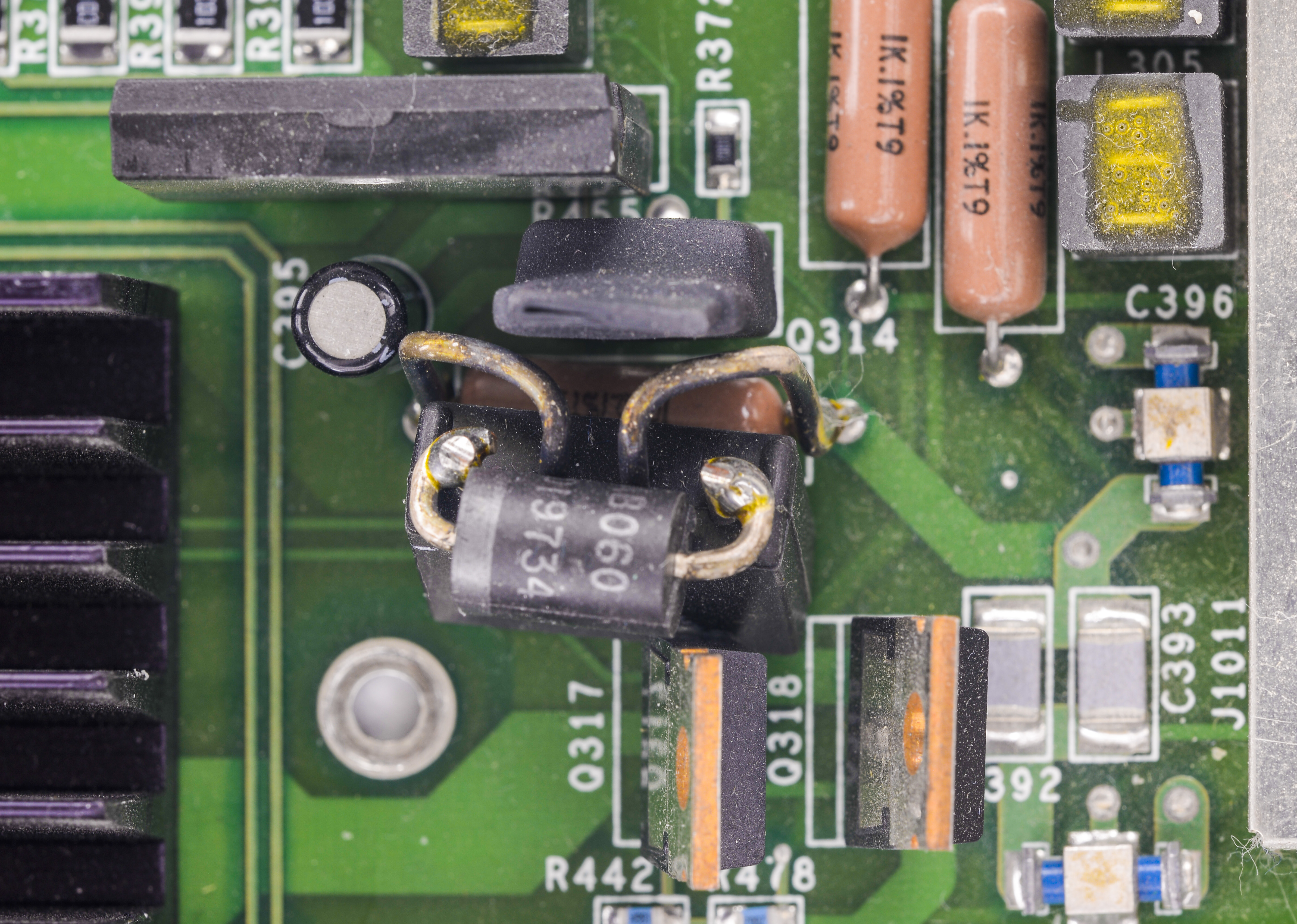
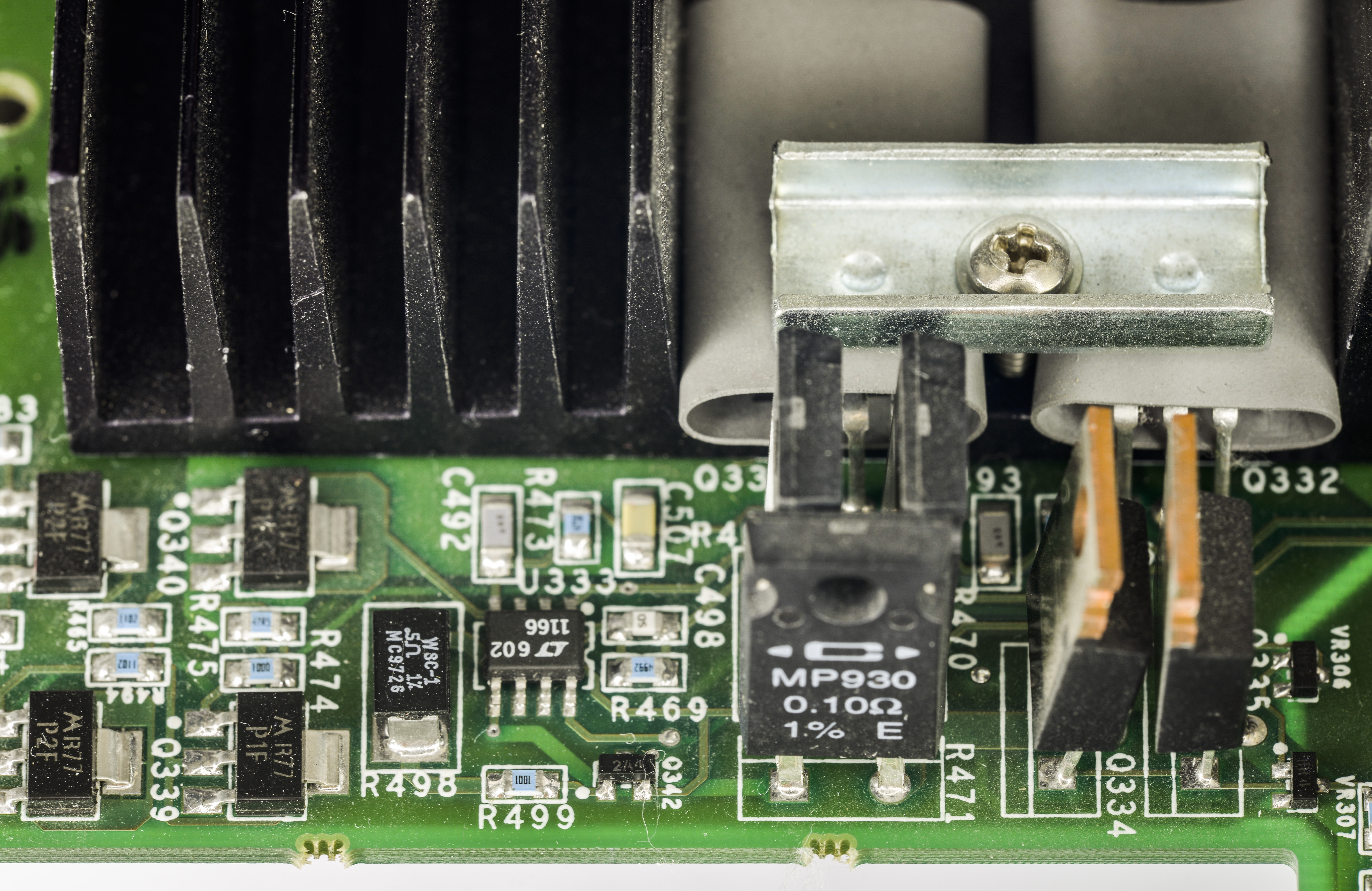
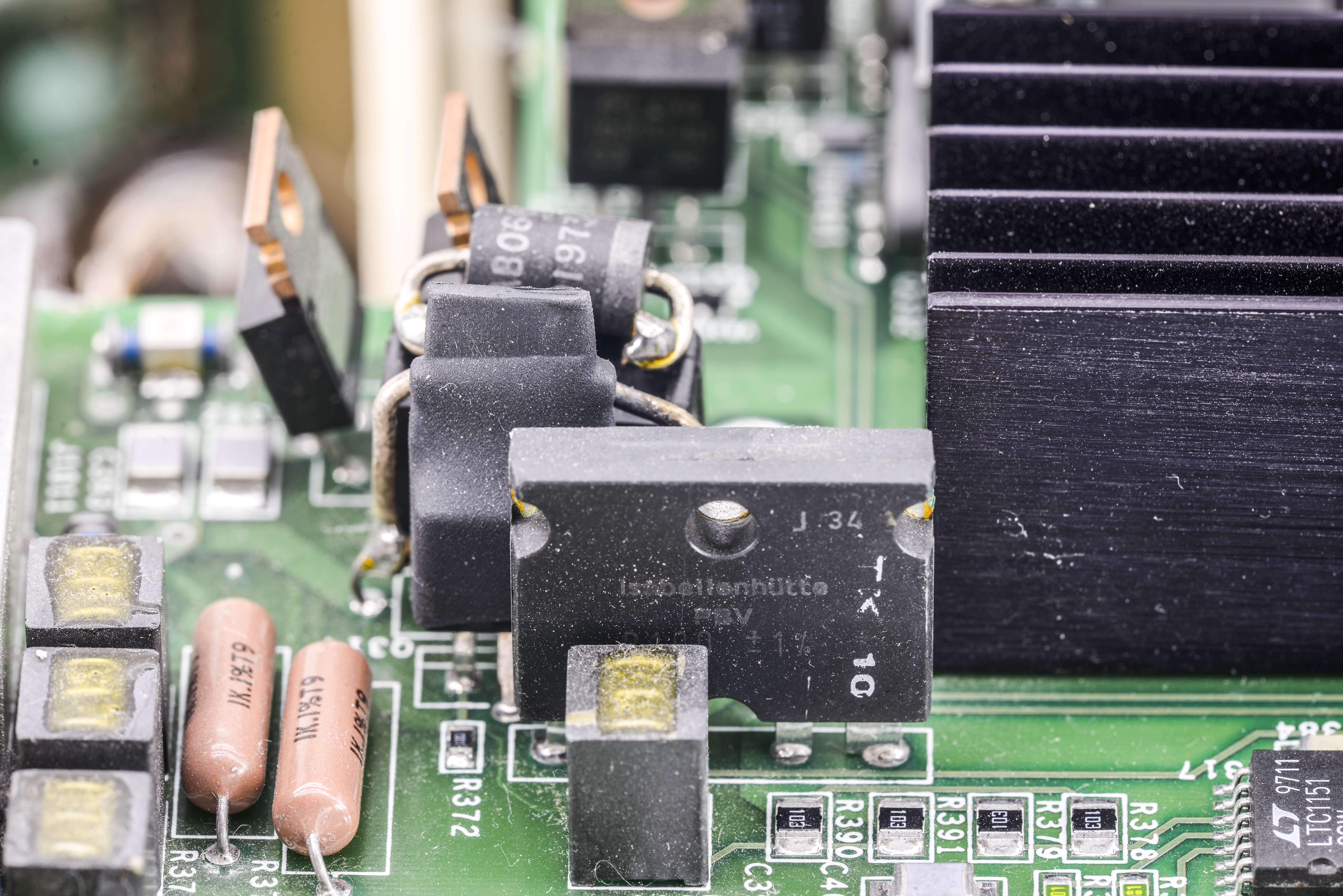
Power shunts, Isabellenhutte 0.1 ohm 1% 4-wire and CADDOCK MP930’s
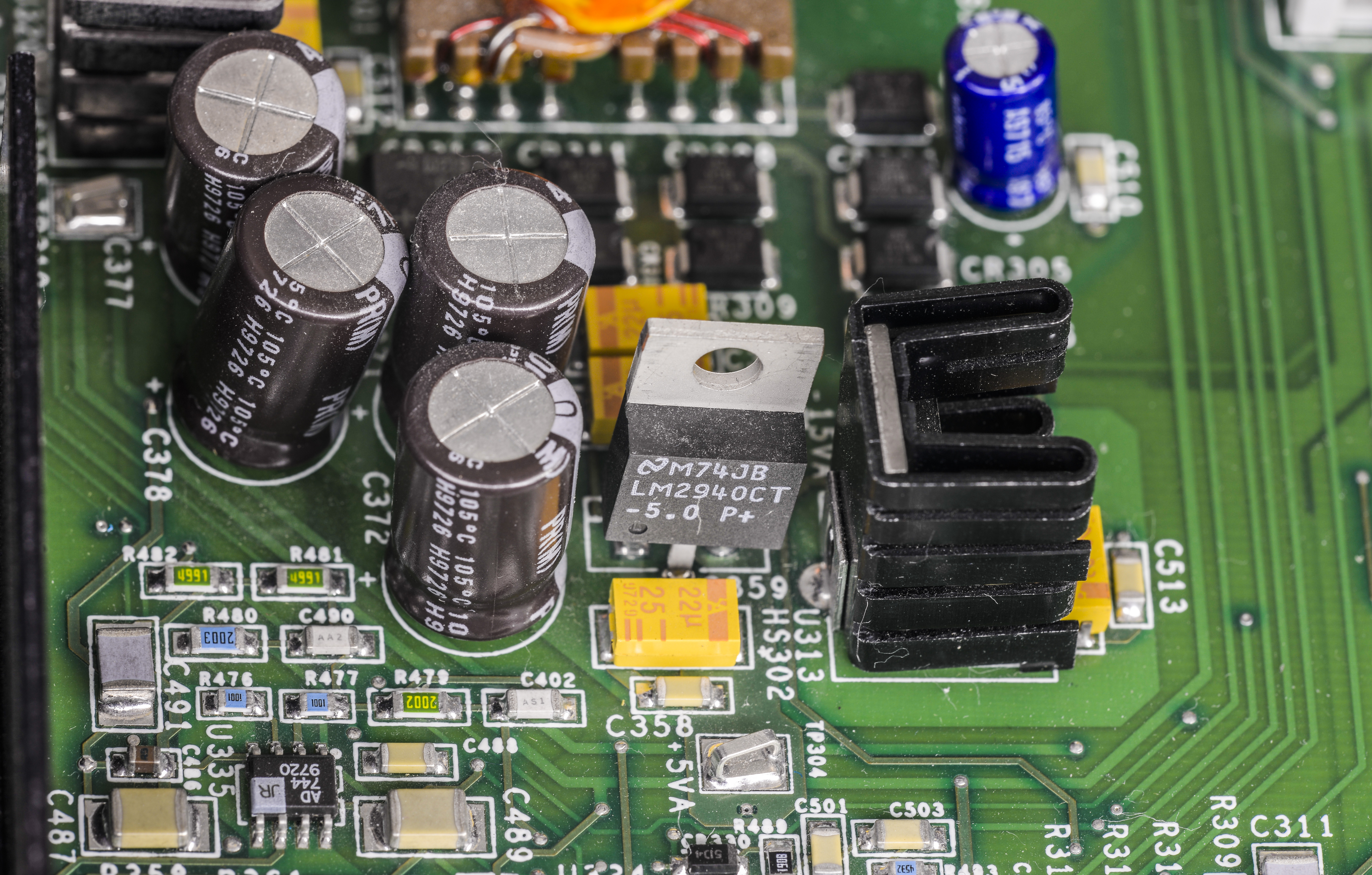
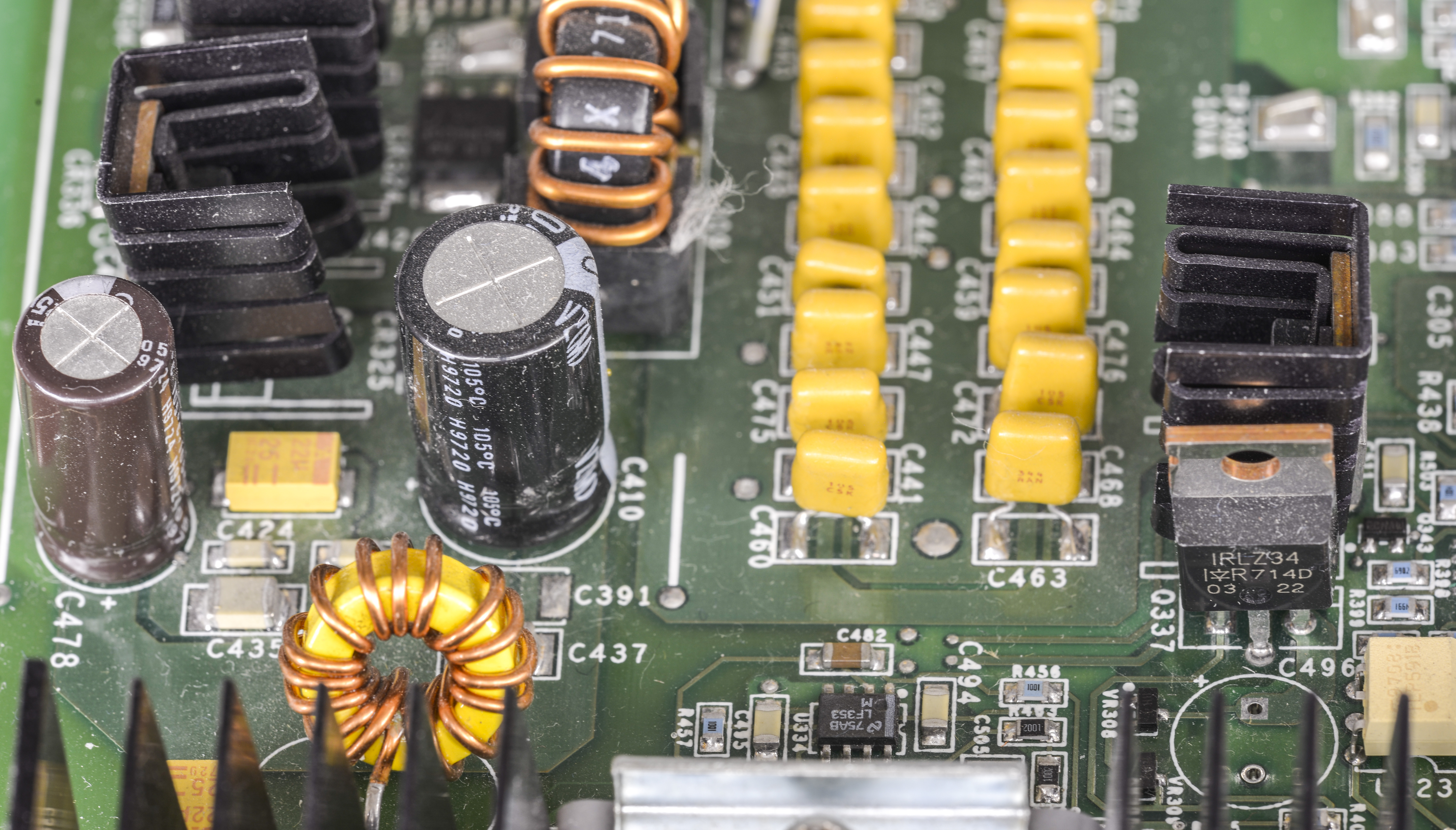


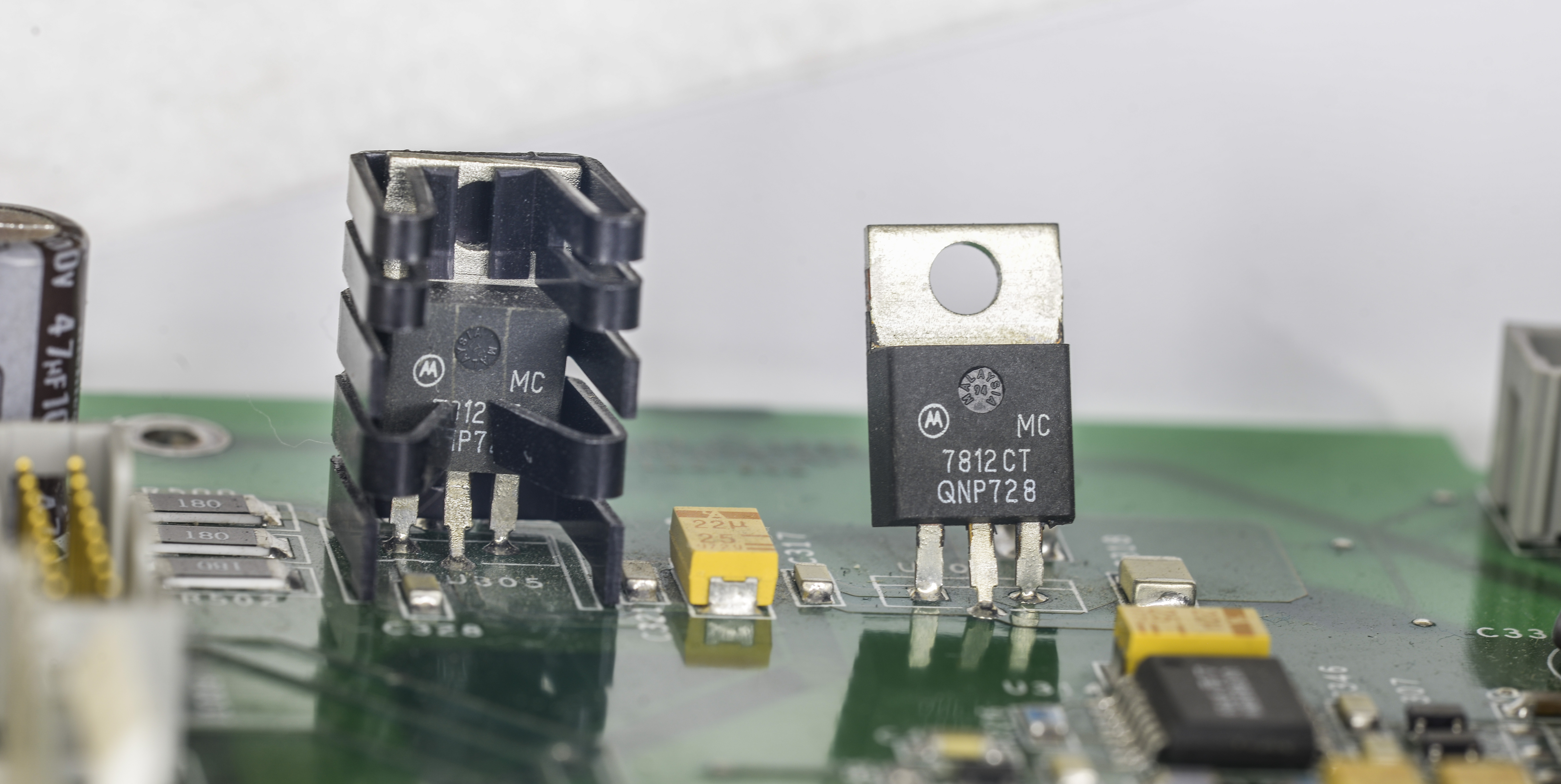
Lonely LDOs to provide positive and negative 12V.
Display board – 2304-112
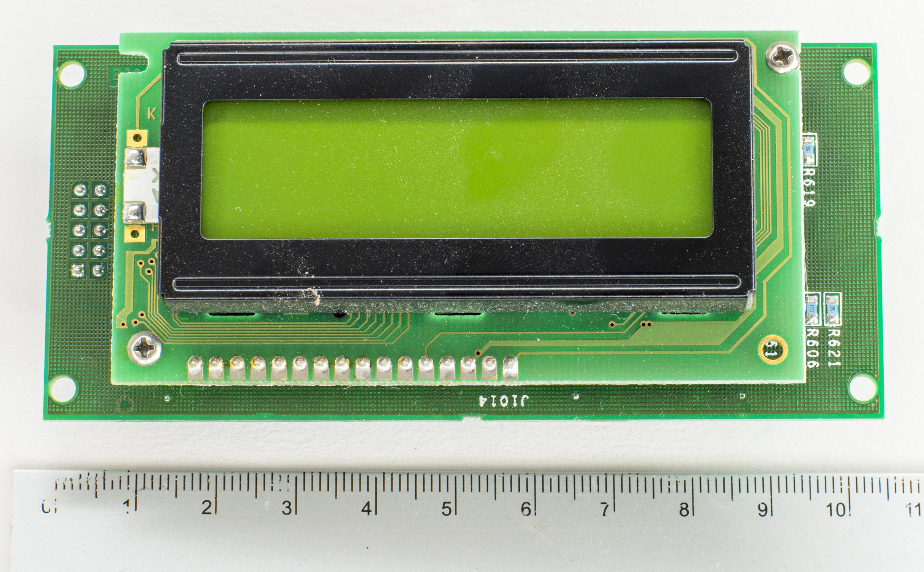
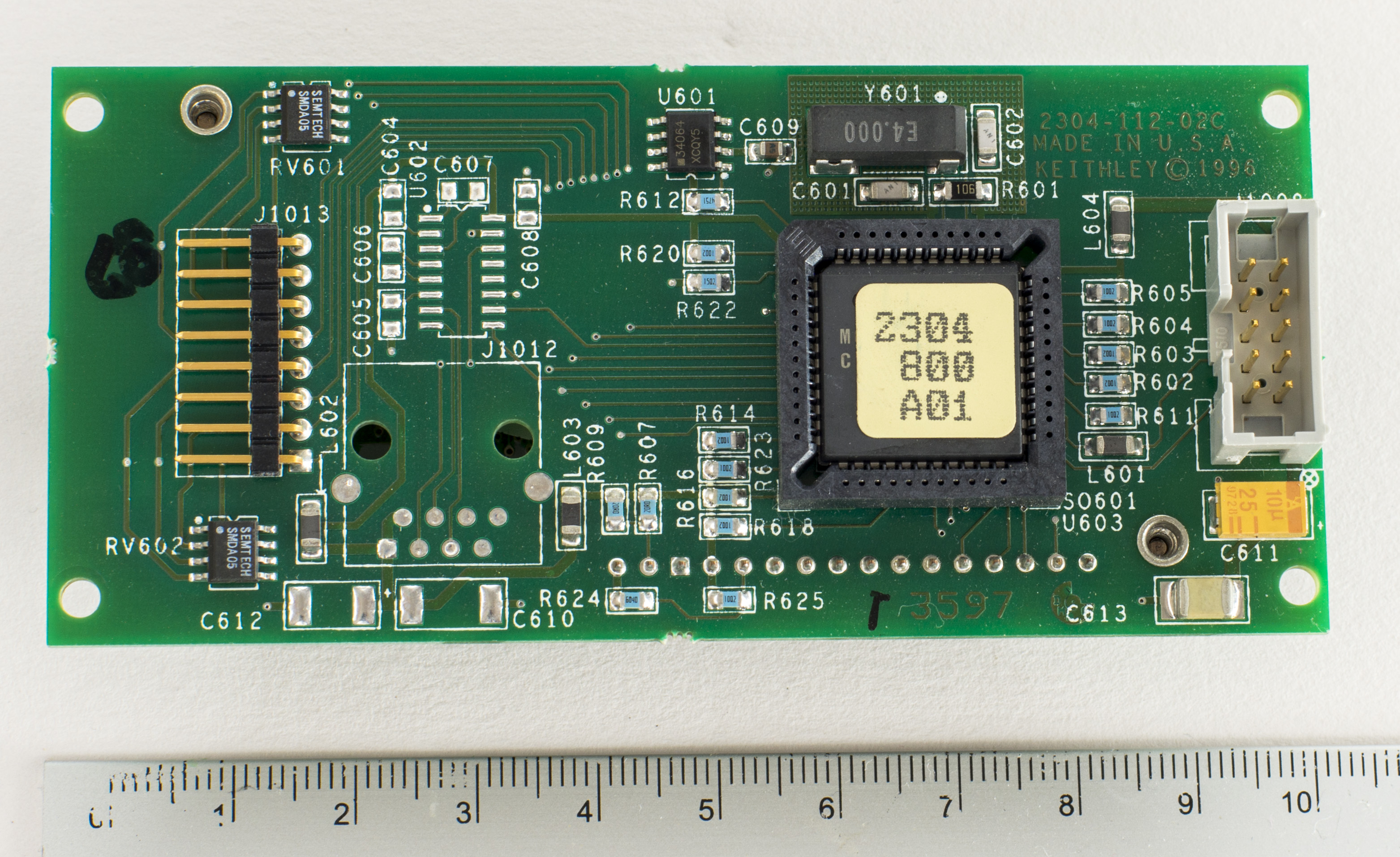
Display module have standard HD44780-compatible 16 × 2 character LCD mounted on custom Keithley’s controller board with 8051 MCU on it. There are also remote display/keypad modules, which plug into RJ45 on the unit’s back to duplicate operation. Could be handy for remote test systems, when PSU is part of bigger system and have no direct access to it.
Repair worklog
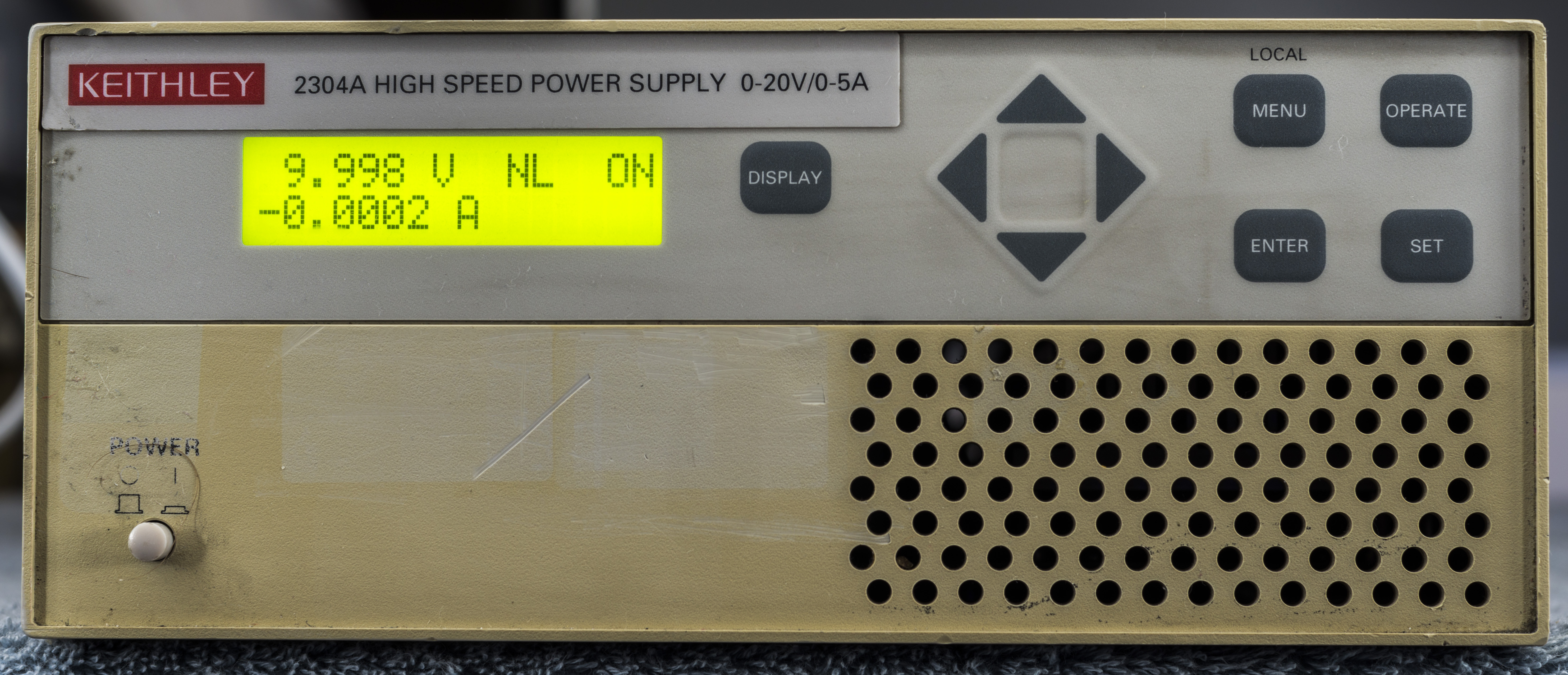
There was not much to repair, as unit was actually functional upon arrival. No magic smoke or burnt parts were detected, output voltage was present and measured spot on with Agilent 34970A, just mere -76 ppm off on +5.000 VDC output and +130 ppm at +20.000 VDC output, which is well within Model 2304 specifications.
Capacitor replacement
Unit made in 2003, but many ICs dates 1997.
Caps on digital board: 220uF 50V x 2, 470uF 25V x 1, 450uF 100V x 2
Analog board: 470uF 63V x 2, 470uF 25V x 2, 47uF 100V x 7, 100uF 25V x 1
Firmware
| Description | Binary file | ODD | EVEN | Motorola SREC/revision list |
|---|---|---|---|---|
| Firmware 2303 Rev. A04, Version 30.1, Mar 23 11:59:16 EST 1999 | Binary 2303-803A04 | |||
| Firmware 2304 Rev. A04, Version 14.1, Aug 2 10:27:55 EDT 2000 | Binary 2304A-803A04 | |||
| Firmware 2303 Rev. A10, Version 45.1, Jul 20 12:35:48 EDT 2011 | Binary 2303-803A10 | SREC source file for 2303 A10 |
Calibration
Recommended test equipment used for calibration this PSU is shown in Table 1-1 from Calibration manual:
| Description | Manufacturer/Model | Specifications |
|---|---|---|
| Digital Multimeter | Keithley 2001 | DC Voltage* 20V: ±22ppm, Resistance* 20Ω ±59ppm, 20kΩ ±36ppm |
| Precision Resistors 2pcs | Isotec RUG-Z-2R002 | 2Ω ±0.1%, 100W** |
| Precision Resistors 4pcs | Dale PTF-56 .1%T13 | 4kΩ, 0.1%, 0.125W*** |
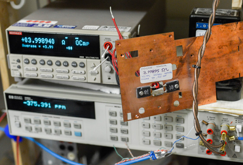
I’ll be using HP 3458A instead of Model 2001 and own DIY resistors. For high power resistors I’ll use pair of CADDOCK MP9100-2.00-1% non-inductive 2Ω resistors 1%, rated for 100W of nominal power. They are available on Digikey for $14 USD each.
4 Ohm resistance reference, tested with calibrated Keithley 2001:
4KΩ resistors tested and assembled from set of 10:
| Resistor number | _ Average of 50 4W NPLC100 measurements by 3458A | Tol |
|---|---|---|
| 1 | 4002.667 Ω | 0.0667 % |
| 2 | 3974.551 Ω | -0.636 % |
| 3 | 4003.083 Ω | 0.0771 % |
| 4 | 3974.384 Ω | -0.640 % |
| 5 | 3984.591 Ω | -0.385 % |
| 6 | 3978.925 Ω | -0.527 % |
| 7 | 3973.005 Ω | -0.675 % |
| 8 | 3970.122 Ω | -0.747 % |
| 9 | 3966.285 Ω | -0.843 % |
| 10 | 3972.308 Ω | -0.692 % |
Final 4KΩ resistor assembly was measured at 200 samples, NPLC100, and resulted 3992.300 Ω which is just -0.192 % from 4KΩ value.
It’s always worth to run performance test prior to any calibration, to check if unit is still working properly and perhaps meeting specifications.
Here is initial data I got by measuring PSU output in four-wire mode (sense and source from PSU connected at 3458A’s input terminals):
Pre-calibration performance data
Calibration example program for EZGPIB using Keithley 2001 and Keithley 2303
Here’s example calibration program, provided by picburner from EEVBLog forums
EZGPIB cal program for K2001+K2303
Calibration GPIB program for Keithley Model 2304A using HP 3458A
xDevs.com Python app : Keithley 2304A + HP 3458A Test and cal
While program looks lengthy and complex, it is actually simple sequental execution of performance test, calibration and final post-calibration performance test.
Example calibration program output:
root@pi2:/repo/2304# python cal2304a.py
 Keithley 2304A PSU calibration tool
  Using NI GPIB adapter with next instruments config:
 * GPIB 5 : Keithley 2304A PSU
 * GPIB 3 : HP 3458A 8.5-digit DMM
 ! Do not swap terminals during calibration!
Keithley Model 2304A - detected, S/N 0672155, Version: A04  /A01
Performance verification for Model 2304 - Voltage source
...
HP3458A detected...Reading DMM temp
HP3458A TEMP = 37.5 C
Press Enter to continue with test...
Enter value of 4R resistor, in ohms, e.g. 3.99895 and press Enter...3.99895
Resistance entered = 3.998950 Ohm
Enter value of 4KR resistor, in ohms, e.g. 3992.3 and press Enter...3992.3
Resistance entered = 3992.300000 Ohm
Press Enter to start cal...
Calibration for Model 2304
Step 0, 19V output
Measured DCV 0 : 1.900140962E+01 VDC
Measured DCV 9 : 1.900110806E+01 VDC
Measured Vout = 19.001221 VDC, Deviation source 64.258632 ppm
Step 2, 19V DVM output
Measured DCV 0 : 1.900108298E+01 VDC
Measured DCV 9 : 1.900101382E+01 VDC
Measured Vout = 19.001037 VDC, Deviation source 54.574421 ppm
STEP 3, connect 4 ohm
Press Enter to continue with cal...
Step 4, 1.9A over 4R
Measured DCV 0 : 7.601433310E+00 VDC
Measured DCV 4 : 7.601538471E+00 VDC
Measured Vout = 7.601489 VDC, Current = 1.900871 A, Deviation source 3000783.570421 ppm
Step 5, 1.9A over 4R
Measured DCV 0 : 7.596521019E+00 VDC
Measured DCV 4 : 7.596600090E+00 VDC
Measured Vout = 7.596559 VDC, Current = 1.899638 A, Deviation source 2998188.816421 ppm
STEP 3, connect 4000 ohm
Press Enter to continue with cal...
Step 7, 5mA over 4K
Measured DCV 0 : 1.900059703E+01 VDC
Measured DCV 4 : 1.900102057E+01 VDC
Measured Vout = 19.000922 VDC, Current = 0.004759 A, Deviation source 3799184420.400000 ppm
Press Enter to save cal...
Saving calibration with date 2016 04 11
It’s quick and simple.
Performance test
Voltage output performance validation test was performed prior to calibration.
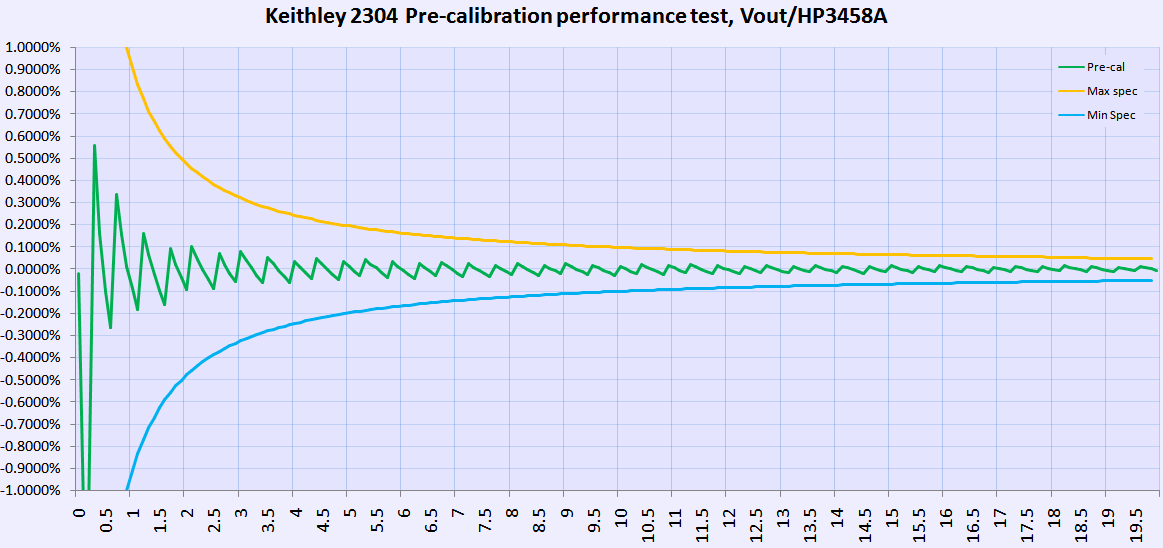
Both output terminals and sense terminals of the PSU was connected to DMM HI/LO inputs for this test. As we can see, even received as is condition is very good and fits power supply specification ±0.05% + 10mV well with good margin.
The maximum common-mode voltage (voltage between LO and chassis ground) is 22VDC. Exceeding this value may cause a breakdown in insulation, creating a shock hazard.
Stability test
TBD..
Display modification
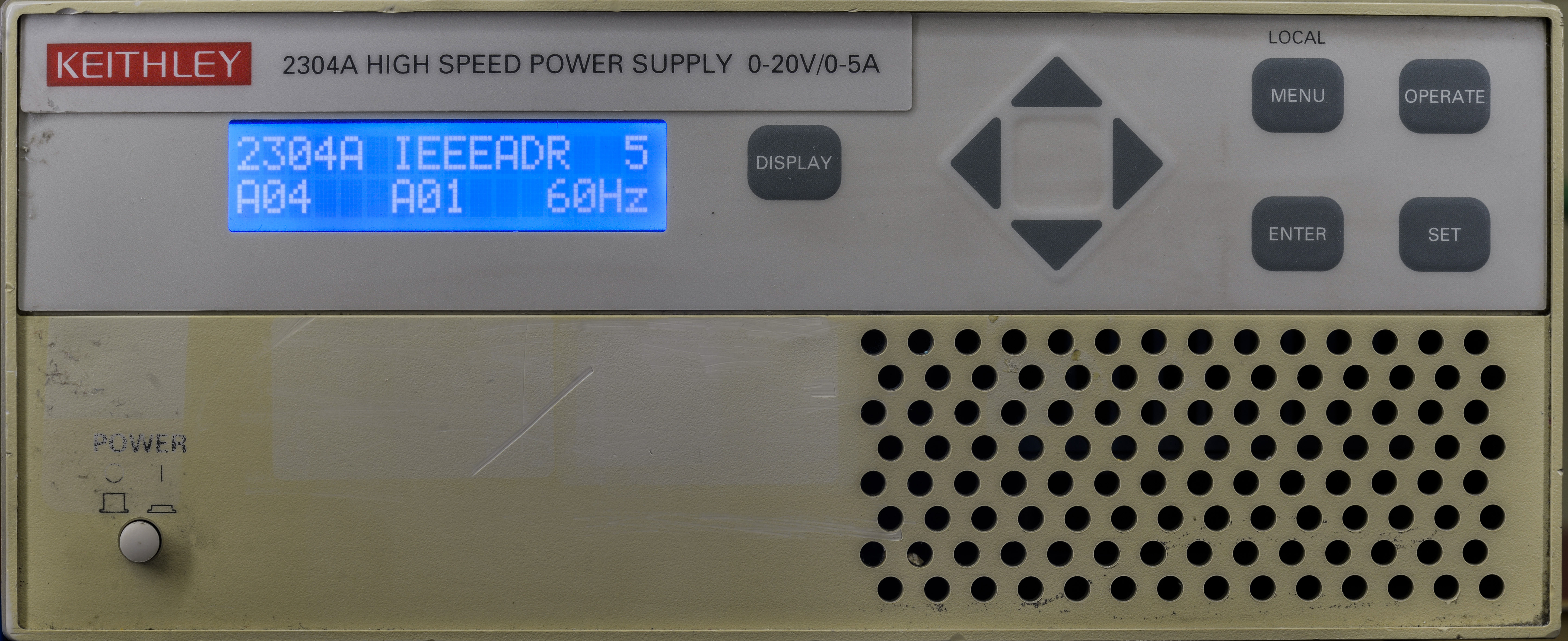
Native LCD is barely visible at any angle except straight 90°, which limits usability of front panel, specially when PSU located on remote area of the bench. One of the easy and quick options for display upgrade are either OLED 16 × 2 or VFD replacement.
I decided to try my luck with OLED, Winstar WEH001602 , with blue color digits and standard HD44780 interface. This display can be bought from Adafruit directly as well.

To my disappointment, this OLED did not work out, first line always shifting characters in random manner, so I resorted to second option , negative blue LCD with white backlight.
h2. Summary and conclusion
| Item | Cost | Shipping | Supplier |
|---|---|---|---|
| Parts Keithley 2304A | 99$ | 115$ | eBay |
| 2 x NOMCT16-2KACT-ND, RES ARRAY 8 RES 2K OHM 16SOIC | 9.16$ | 0$ | DigiKey USA |
| 2 x MP9100-2.00F-ND, RES 2 OHM 100W 1% TO247 | 24.56$ | 0$ | DigiKey USA |
| 10 x RSB-4.0KRCT-ND, RES 4.0K OHM 3W 1% WW AXIAL | 15.69$ | 0$ | DigiKey USA |
| 1 x WINSTAR WEH001602ABPP5N000000 16 × 2 OLED | 43.30$ | 13.45$ | eBay |
Table 20: Project cost total
Total spent on this PSU: $320.16 USD
| Date | Activity | Time spent |
|---|---|---|
| 2/25/2016 | Unit shipped from eBay via USPS | |
| 3/7/2016 | Received unit, initial teardown | 1 hour |
| 3/7/2016 | Repair evaluation, testing onboard power, read firmware | 1 hour |
| 4/8/2016 | LCD replacement for OLED, calibration | 4 hours |
| Taking photos, writing up article sections and posts | 4 hours |
Table 22: Time worklog summary
Total man-hours spent on this project around 10 hours, give or take few.
Equipment used during repair project:
- Soldering gear, ERSA I-CON station
- MiniPro TL866CS programmer to read/write ROMs/RAMs
- Keithley 2001 DMM (calibration 02/2014)
- HP 3458A DMM for calibration purposes
- ESI DB52 resistance decade to test low current operation
- Set of Vishay foil resistors for resistance artifact calibration
- xDevs.com’s Photo setup
This instrument will be used in my daily lab operation for analog and digital designs.
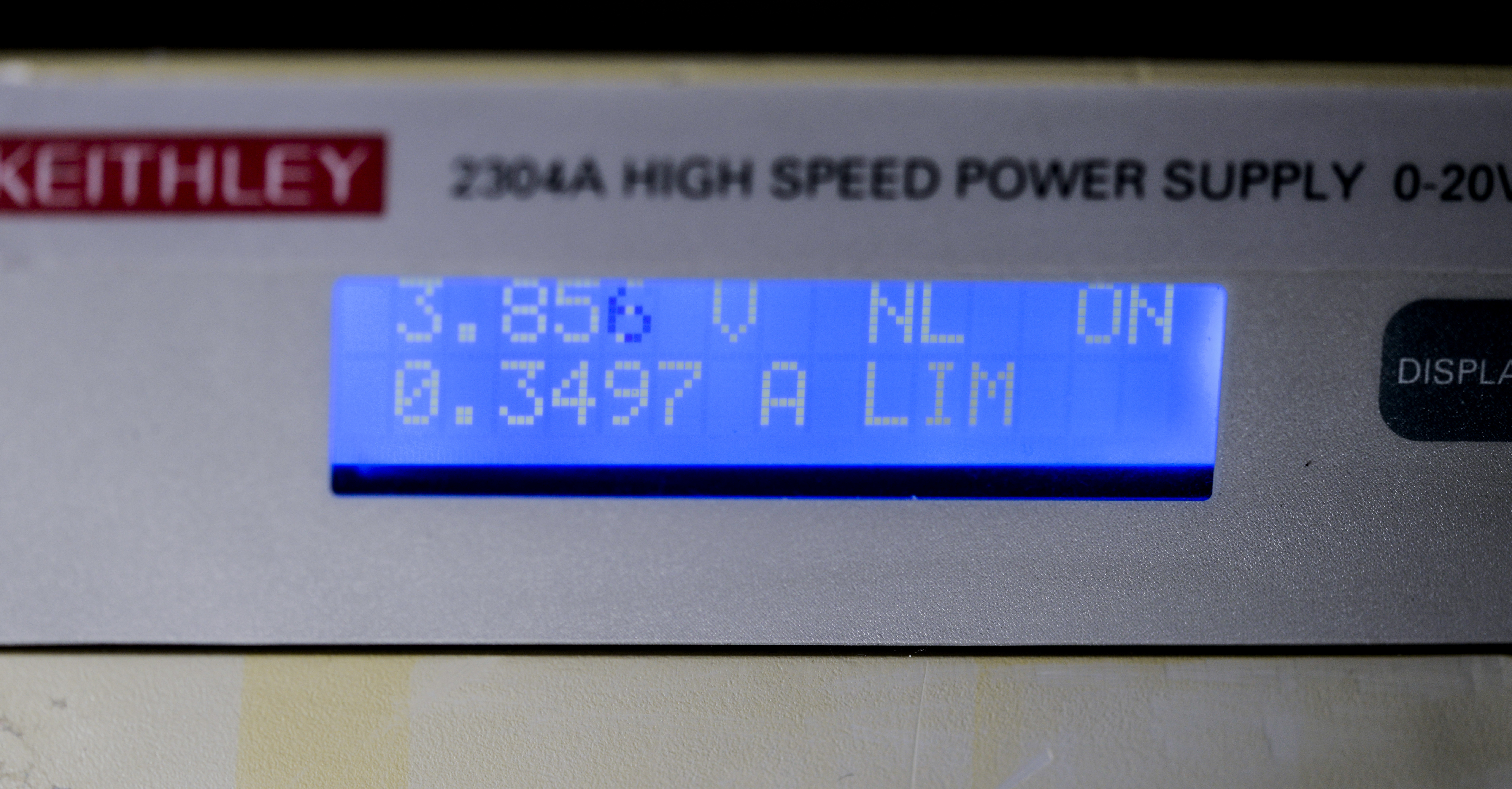
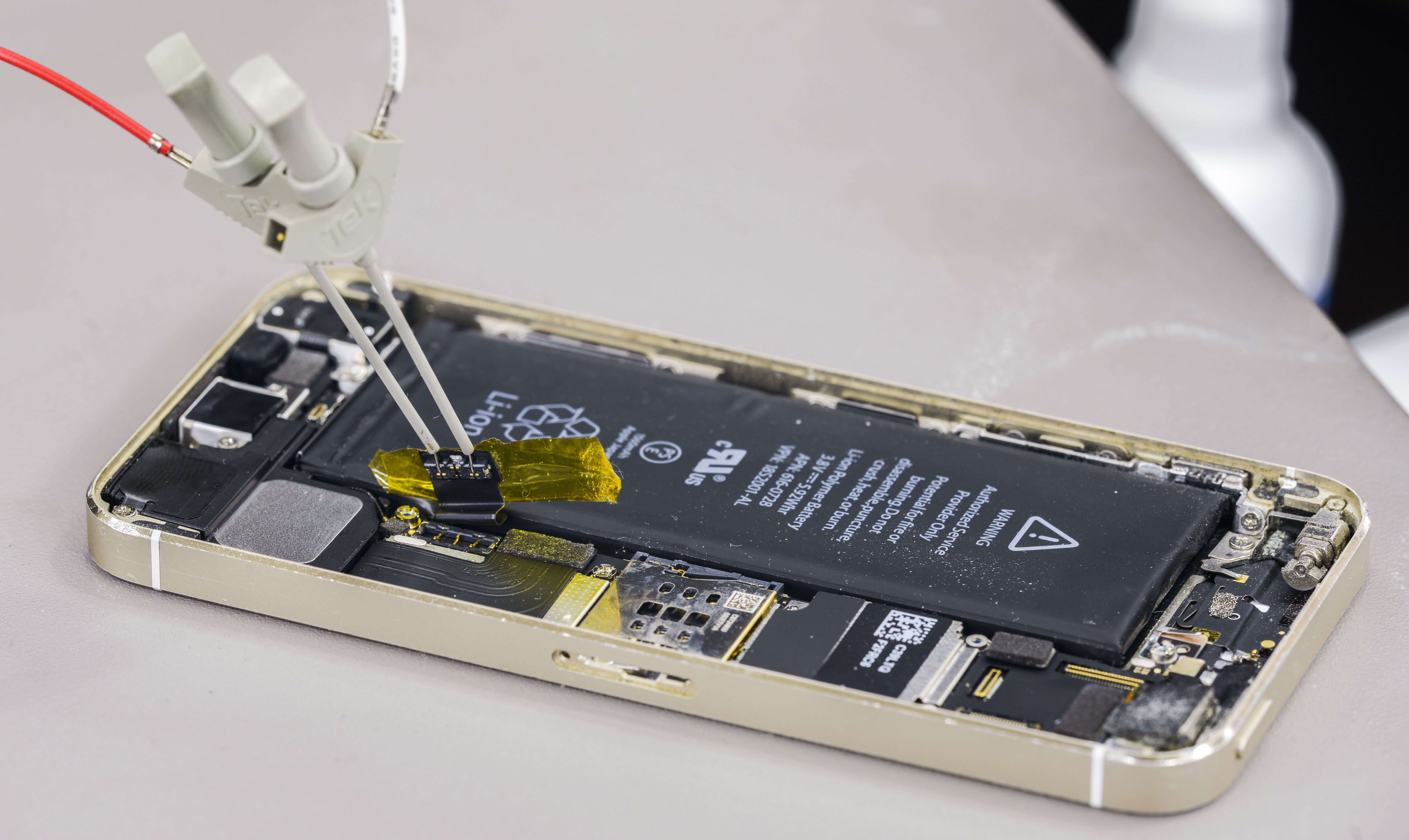
And first application was reviving dead phone battery, which was accomplished without issues.
If you like the article or have any questions, comment section waiting for you.
Projects like this are born from passion and a desire to share how things work. Education is the foundation of a healthy society - especially important in today's volatile world. xDevs began as a personal project notepad in Kherson, Ukraine back in 2008 and has grown with support of passionate readers just like you. There are no (and never will be) any ads, sponsors or shareholders behind xDevs.com, just a commitment to inspire and help learning. If you are in a position to help others like us, please consider supporting xDevs.com’s home-country Ukraine in its defense of freedom to speak, freedom to live in peace and freedom to choose their way. You can use official site to support Ukraine – United24 or Help99. Every cent counts.
Modified: April 11, 2016, 1:54 a.m.