Contents
- Intro
- Hardware overview
- Setting up
- Install Kernel source package for library headers support
- Install required library set for linux-gpib
- Configuration for linux-gpib and interfacing
- Testing GPIB operation
- Python-application to talk GPIB from DE1-SoC
- Additional interfaces, LXI via Python
Intro
Affordable ($250 USD) Terasic DE1-SoC Development Kit is a design evaluation platform, using Altera’s Cyclone V System-on-Chip (SoC) FPGA. These SOC combine the dual-core Cortex-A9 ARM processor with FPGA fabric for wide array of use cases. It’s not just a processor glued to FPGA, as Altera’s SoC integrates complete hard processor system (HPS) consisting of processor itself, I/O peripherals and memory interfaces, including FPGA fabric high-bandwidth interconnect backbone.
This kit is good candidate to have complete all-in-one system for applications like data aquisition systems with friendly front-panel UI, industrial and home automation, sensor processing, high-speed data processing and web-controlled systems. There are various Linux and Android packages supported on ALTERA’s HPS section, allowing quick development of high-level applications boosted with FPGA performance and flexibility. High-speed bridge interface between HPS and FPGA capable of multi-gigabit speeds and has transparent memory mapping.
For reference, we have used and reviewed also few other Terasic boards, such as DE-nano.
Overview of key onboard features:
- Cyclone V SoC 5CSEMA5F31C6 Device, 85K LE, 4,450 Kbits embedded memory
- Dual-core ARM Cortex-A9 (HPS) (up to 925MHz)
- 6 Fractional PLLs, 2 Hard Memory Controllers
- 64MB (32Mx16) SDRAM on FPGA
- 1GB (2×256Mx16) DDR3 SDRAM on HPS
- Micro SD Card Socket on HPS (supports both SDHC/SDXC)
- Two Port USB 2.0 Host (ULPI interface with USB type A connector)
- USB to UART using FTDI232 (micro USB type B connector)
- 10/100/1000 RJ45 Ethernet
- PS/2 mouse/keyboard
- Two 40-pin Expansion Headers (voltage levels: 3.3V)
- One 10-pin ADC Input Header tied to SAR ADC with 500 KSPS, 8ch 12 bit Linear LTC2308
- One LTC connector (One Serial Peripheral Interface (SPI) Master ,one I2C and one GPIO interface) at HPS
- 24-bit VGA DAC and output
- 4 User Keys (FPGA x4), 10 User switches (FPGA x10), 11 User LEDs (FPGA x10 ; HPS x 1)
- 2 HPS Reset Buttons (HPS_RST_n and HPS_WARM_RST_n)
- Six 7-segment LED displays
- On-Board ALTERA USB Blaster II (Normal type B USB connector)
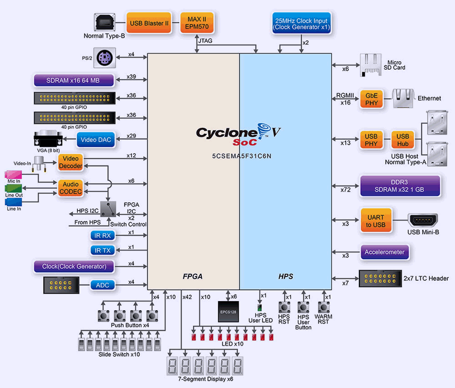
FPGA section has lot of I/O and peripherals handy for user applications and debug, while ARM-based HPS section provide high level application layer interfaces, such as GbE network, USB Hub with two ports, UART via USB interface bridge, onboard Accelerometer and LTC header with I2C/SPI.
Hardware overview
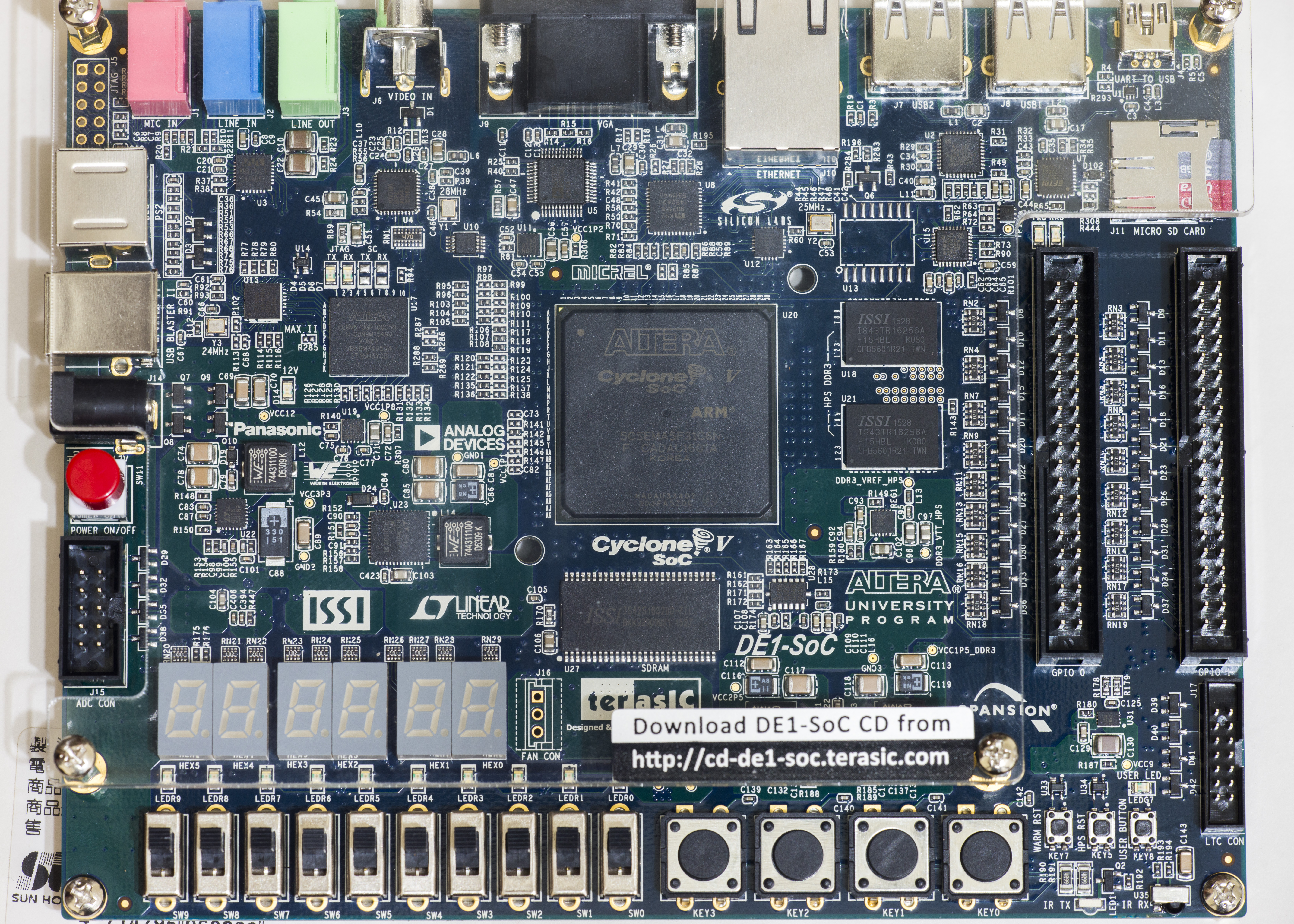
Terasic DE1-SoC have medium size, very similar to older DE1 and has nice acrylic protection screen on top, to avoid metal objects or bare wires which may fall on the board cause major disasters. Handy for average engineering table mess. Bottom side not protected, but lifted of the surface with brass standoffs.
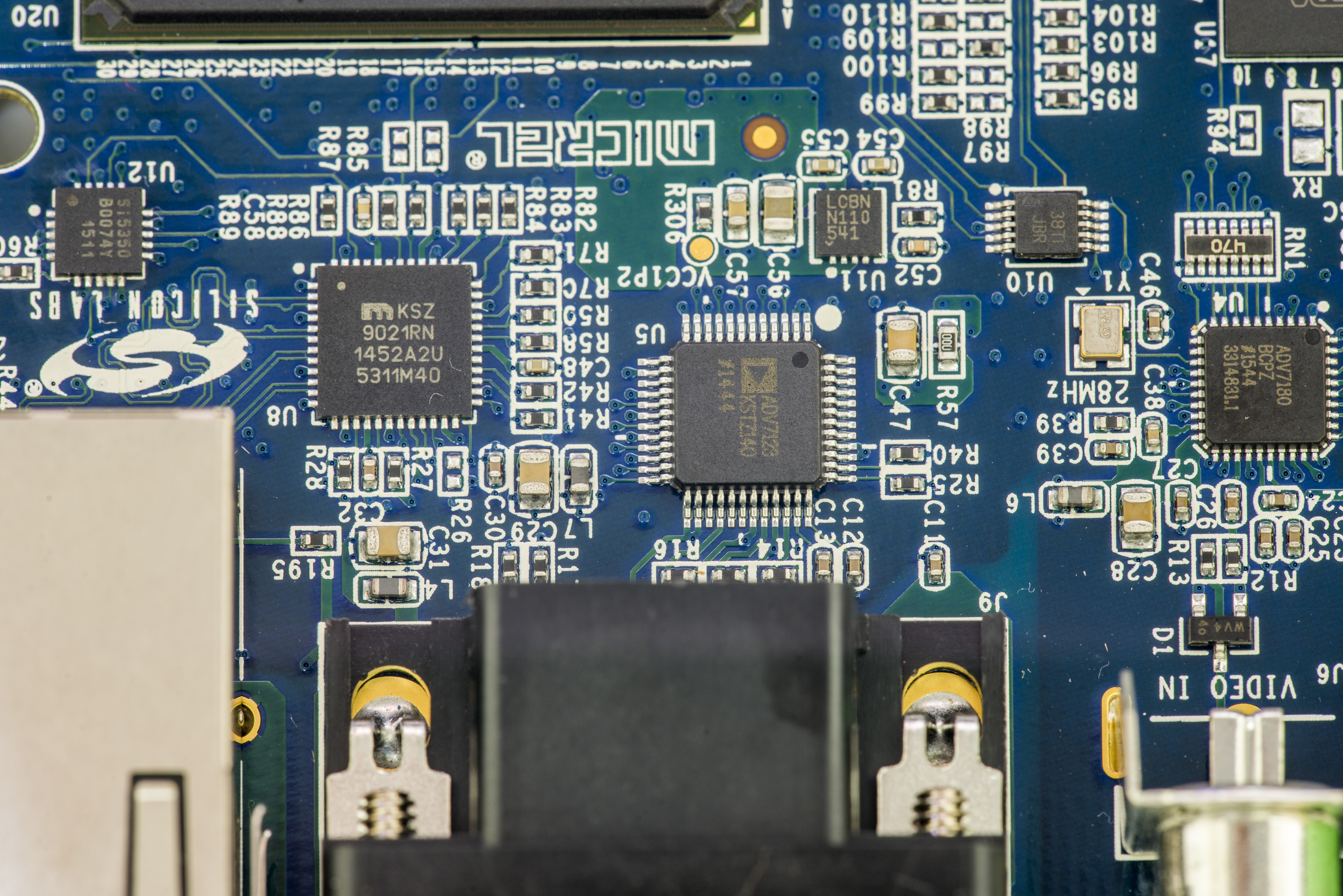
FPGA-attached VGA display output use integrated DAC solution, Analog Devices ADV7123 (U5). There is also Video IN DAC, ADV7180. For connectivity 1GbE LAN port served thru Microchip KSZ9021. Unpopulated programming JTAG port J5 on the corner connects to USB Blaster MAX CPLD, and normally not required.
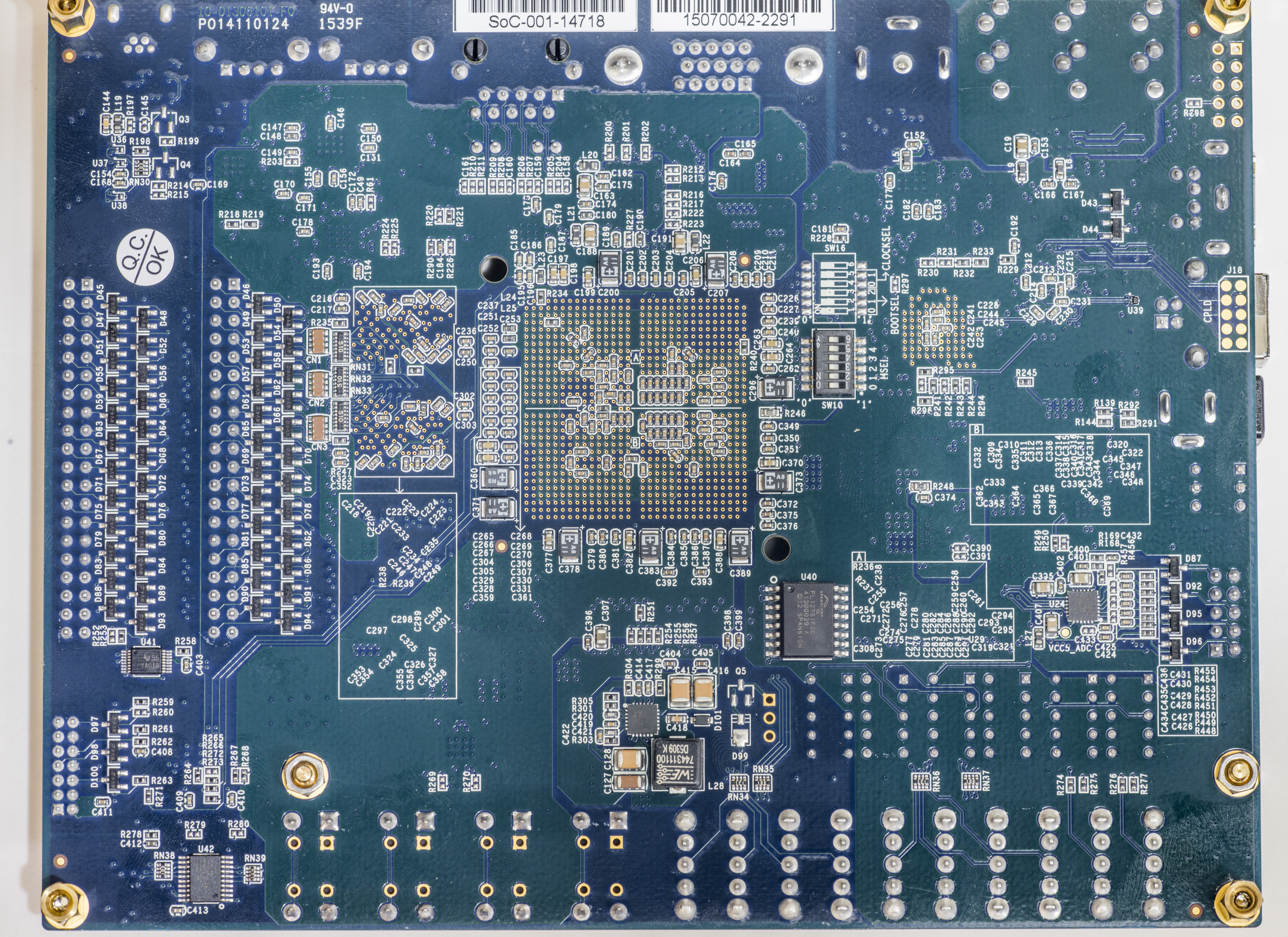
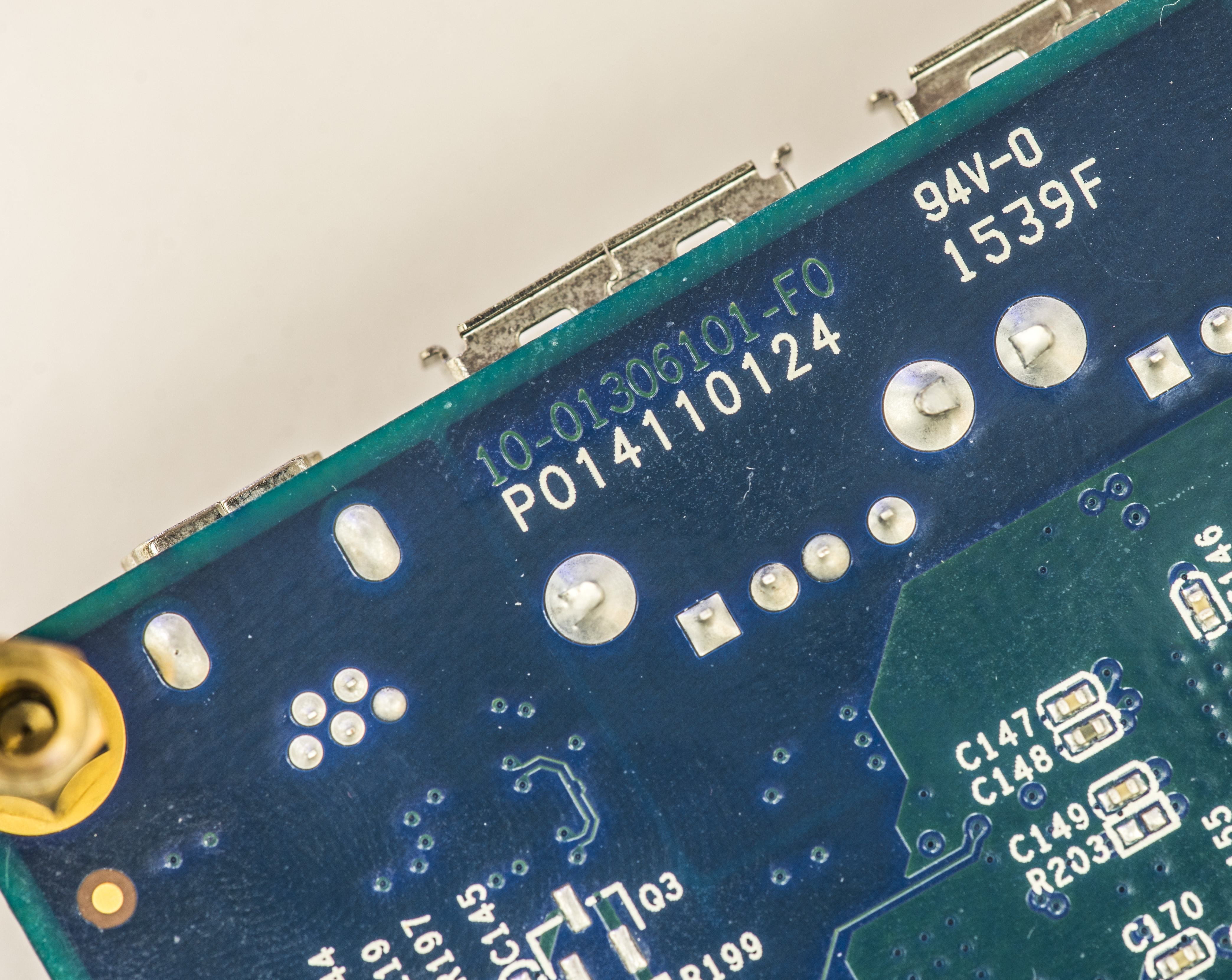
FPGA chip itself is large FBGA device, manufactured in Korea first week of 2016. Pair of ISSI DDR3 SDRAM packages nearby providing 1GB for HPS. Terasic does not provide board layout files but with bit of time one could get access to FPGA’s pins, as most of balls dogbone vias are exposed on the bottom side.
Single SDRAM package in TSSOP provides just 64MB memory to FPGA section, which might be not enough in some data-intensive cases. For such applications Arrow SoCkit board or “ALTERA/Intel Cyclone® V SoC Development Kit” might be better, yet much more expensive options. U28 is the accelerometer in LGA package. Power DC-DC nearby is Linear LTC3633
Configuration switch on bottom side allow to set MSEL pin straps and define boot procedure of the board.
FPGA bitstreams are stored in Flash ROM on bottom. Unpopulated Q5 and D99 are parts for unused 3-pin FAN header. Could be handy if one has full utilization of FPGA+HPS resources, as Cyclone V getting rather hot under operation.

Another power DC-DC, this time 8A Linear LTC3608 and 5A Linear LTC3605 and lonely Linear LT3080 LDO with LCBN marking.
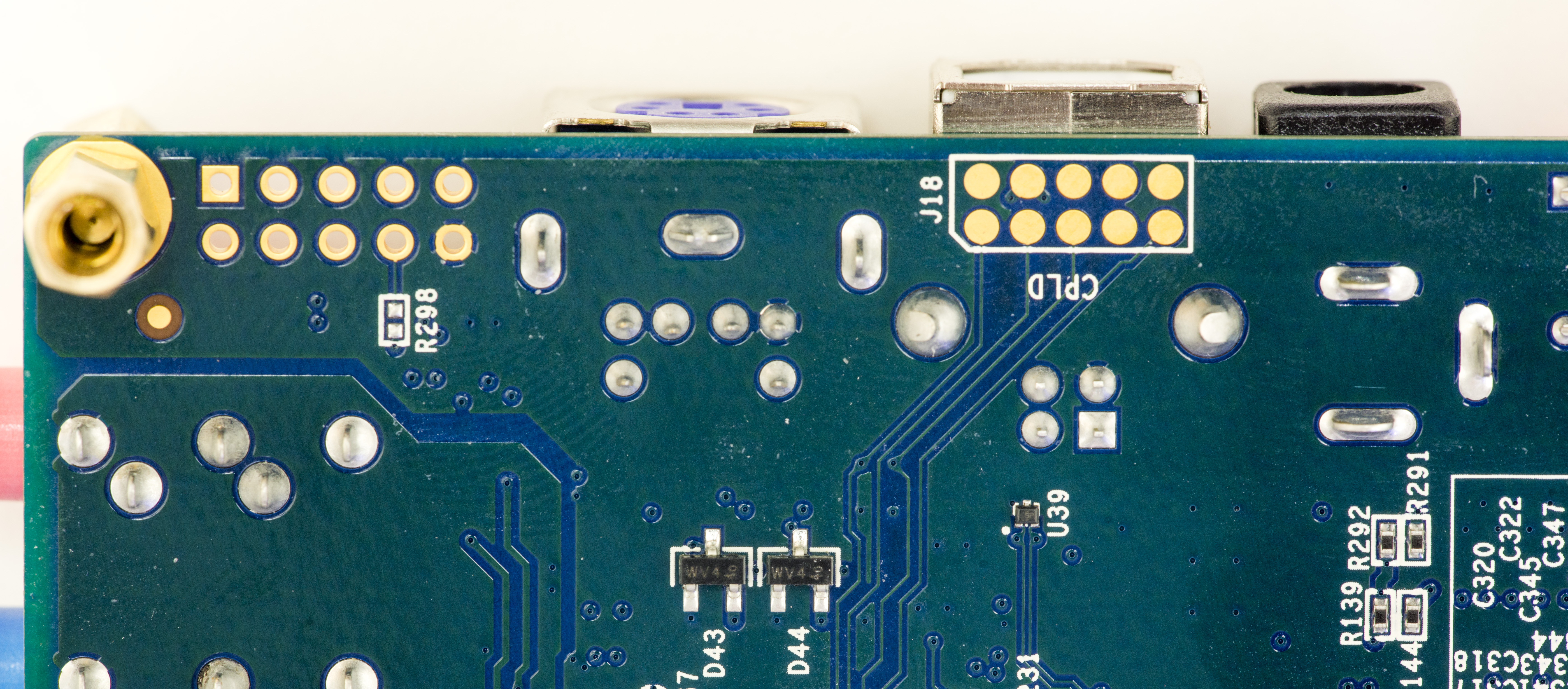
HPS section has own Warm and Cold reset buttons, user button and one user LED. Here are also infrared transmitter and receiver. LTC header has with standard pinout, defined by Linear QuickEval development board format.
| Description | Pin | Pin | Description |
|---|---|---|---|
| Power supply V+, 9VDC | 1 | 2 | +3.3V VCCA |
| GND | 3 | 4 | HPS SPIM SCK or I2C SCL |
| HPS SPIM MISO input | 5 | 6 | HPS SPIM Chip Select SS |
| HPS MOSI or I2C SDA | 7 | 8 | GND |
| HPS I2C2 SDA | 9 | 10 | +3.3V Power |
| HPS I2C2 SCL | 11 | 12 | GND |
| GND | 13 | 14 | HPS LTC GPIO pin |
Table 1: LTC connector pin definition on DE1-SoC
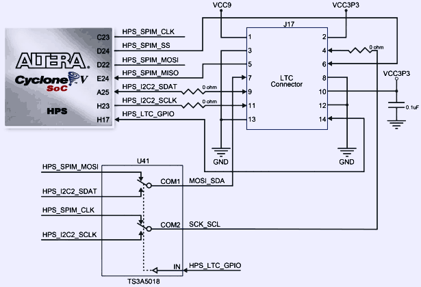
Make sure you set mux switch correctly, depends on either you want to route I2C/SPI to HPS section or FPGA.
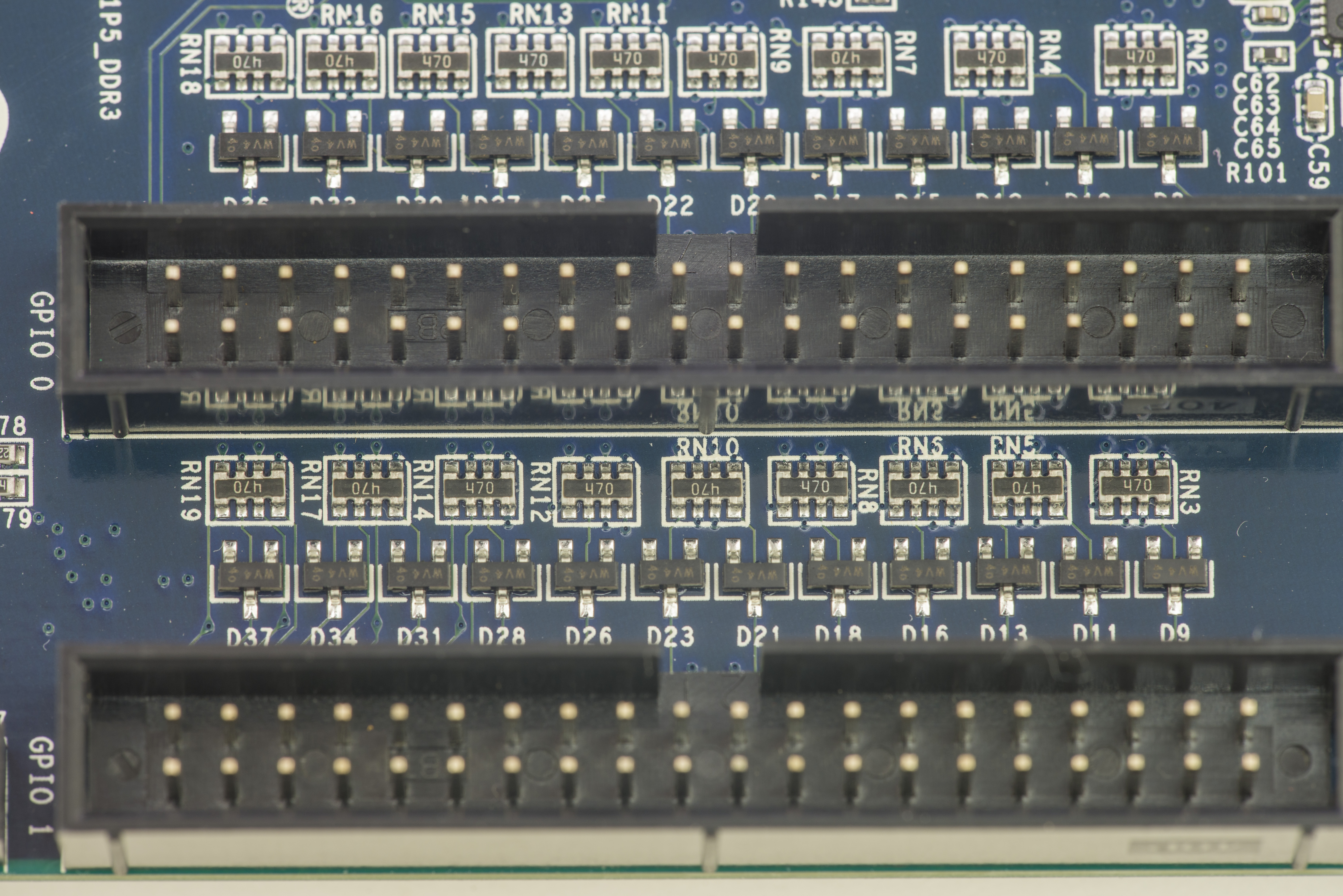

GPIO ports from FPGA on this board are regular 0.1” (2.54mm) pitch 40-pin headers, easy to use for prototyping and hobby projects without expensive HSMC adapters. All pins have +3.3V protection with diodes.


USB-UART is based on common and robust FTDI. Native USB 2.0 connectivity provided by SMSC USB3300 PHY and SMSC USB2512B 2.0 Hub. Connector for microSD memory card supports both SDHC and SDXC cards.
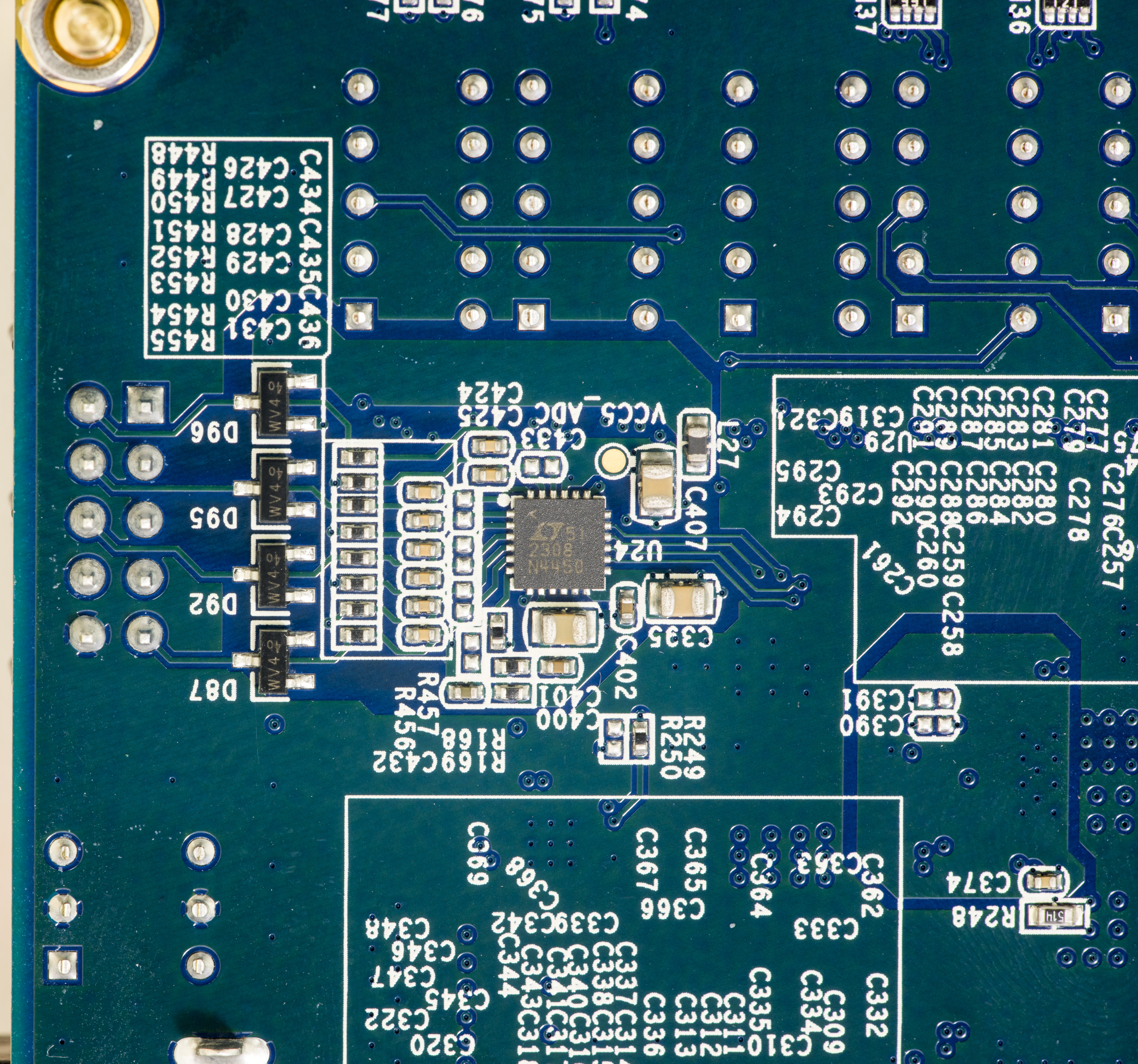
Onboard 8-channel ADC is Linear LTC2308 able to provide 12 bits of resolution at 500 KSPS speed. It has internal 2.5V reference voltage. Nothing very special, but nice to have to sample some sensors and voltages. Maximum input voltage is 4.096VDC.
And all this was on latest Rev.F version board. Older boards used different ADC, different JTAG chain configuration. Changeset and manuals for each board revision available on Terasic site.
Setting up
I wanted to use Debian-based Linux distro on DE1-SoC to follow similar to Raspberry Pi toolkit and workflow. Image build October 18, 2016 from ALTERA was used as getting started point. It requires at least 8GB SD card and has Linux Kernel version 3.18.
Of course you can build your own Linux image for DE1-SoC, following one of the guides available on web, such as Preloader and U-Boot Customization from Rocketboards.org
Image linked above has next features:
- Wifi drivers built into kernel + firmware
- Added VNC server which automatically runs on boot
- VNC display size can be adjusted using xrandr
- clipboard sharing support
- Default STATIC ip 192.168.0.123 on eth0:1 and 192.168.1.123 on eth0:2
- FTP server (user: root password: password)
Since image supplied by Terasic DE1-SoC is based on old Ubuntu 12.04 “Precise” LTS which will go EOL in January 2017, worth to consider an update at least to 14.04 LTS. Chapter how to do this is covered below here.
root@de1soclinux:~# lsb_release -a
No LSB modules are available.
Distributor ID: Linaro
Description:    Linaro 12.11
Release:        12.11
Codename:       precise
After successful boot, in file /etc/network/interfaces add auto eth0 line before first iface eth0 so we get network up on boot automatically.
root@de1soclinux:~# cat /etc/network/interfaces
# interfaces(5) file used by ifup(8) and ifdown(8)
auto lo
iface lo inet loopback

allow-hotplug eth0
auto eth0
iface eth0 inet dhcp

auto eth0:1
iface eth0:1 inet static
        address 192.168.1.123
        netmask 255.255.255.0

auto eth0:2
iface eth0:2 inet static
        address 192.168.0.123
        netmask 255.255.255.0
Now we can make sure eth0 got IP address and try to connect to DE1-SoC via PuTTy or other favourite SSH terminal tool. DE1-SoC has only 1 GByte of RAM, so it might be useful to create swap partition with tool like cfdisk and assign it for use:
root@de1soclinux:~# mkswap /dev/mmcblk0p5
Setting up swapspace version 1, size = 1999988 KiB
no label, UUID=ee41c5da-5774-4bbd-ac23-0ca713092ed5
root@de1soclinux:~# swapon -U ee41c5da-5774-4bbd-ac23-0ca713092ed5
root@de1soclinux:~# blkid /dev/mmcblk0p5
/dev/mmcblk0p5: UUID="ee41c5da-5774-4bbd-ac23-0ca713092ed5" TYPE="swap"
root@de1soclinux:~#
Changes can be made permanent by adding line in /etc/fstab:
root@de1soclinux:/etc# cat /etc/fstab
UUID=ee41c5da-5774-4bbd-ac23-0ca713092ed5 none swap sw 0 0
Check amount of available space:
root@de1soclinux:/etc# swapon -s
Filename                                Type            Size    Used    Priority
/dev/mmcblk0p5                          partition       1999988 0       -1
By default this image does not use all available space on card, so let’s move /usr to separate partition.
I’ve created 6th partition on used 32GB SD card and now format it with ext4 FS.
root@de1soclinux:/# mkfs -t ext4 /dev/mmcblk0p6
Read new FS UUID:
root@de1soclinux:/# blkid /dev/mmcblk0p6
/dev/mmcblk0p6: UUID="6fab2f5b-6eed-41ba-9934-fb1da856e308" TYPE="ext4"
Modify /etc/fstab again to add partition:
root@de1soclinux:/# cat /etc/fstab
UUID=ee41c5da-5774-4bbd-ac23-0ca713092ed5 none swap sw 0 0
UUID=6fab2f5b-6eed-41ba-9934-fb1da856e308 /storage ext4 relatime,errors=remount-ro 0 1
Now reboot and make sure that new FS on mount point /storage is nice and healthy. Now let’s move all /usr contents which reside on root 4GB parition to new partition. It’s important to keep symlinks correct, so use next command:
rsync -av /usr/* /storage
This will move about 2.1GB of data to new partition. Now we can update mount point from /storage to /usr and reboot system.
root@de1soclinux:/# cat /etc/fstab
UUID=ee41c5da-5774-4bbd-ac23-0ca713092ed5 none swap sw 0 0
UUID=6fab2f5b-6eed-41ba-9934-fb1da856e308 /usr ext4 relatime,errors=remount-ro 0 1
root@de1soclinux:/# reboot
If everything goes well, we should see disk mapping like below:
root@de1soclinux:/# df -h
Filesystem      Size  Used Avail Use% Mounted on
/dev/root       4.2G  476M  3.5G  12% /
devtmpfs        244M  4.0K  244M   1% /dev
none             75M  540K   74M   1% /run
none            5.0M     0  5.0M   0% /run/lock
none            372M  4.0K  372M   1% /run/shm
/dev/mmcblk0p6   22G  2.1G   18G  11% /usr
/dev/mmcblk0p1  2.0G  6.4M  2.0G   1% /media/fat_partition
Let’s install MC.
root@localhost:~# apt-get install mc
Reading package lists... Done
Building dependency tree
Reading state information... Done
E: Unable to locate package mc

This is because by default only core packages are included in source-repostiries list. To add 3rd party packets, you will need to add "universe" repository by editing /etc/apt/sources.list and uncomment universe lines:
sudoedit /etc/apt/sources.list
Like so:
deb http://ports.ubuntu.com/ubuntu-ports/ precise universe
deb-src http://ports.ubuntu.com/ubuntu-ports/ precise universe
deb http://ports.ubuntu.com/ubuntu-ports/ precise-updates universe
deb-src http://ports.ubuntu.com/ubuntu-ports/ precise-updates universe
Update 12.04 LTS to 14.04 LTS
You may also want to update for latest Ubuntu LTS version. To do so, execute sudo do-release-upgrade and follow instructions. “Precise” version is 12.04 LTS and it can be updated to “Trusty” 14.04 LTS. To upgrade for latest “Xenial” 16.04 LTS you will need to run upgrade once again.
root@de1soclinux:/usr# sudo do-release-upgrade
Checking for a new Ubuntu release
Get:1 Upgrade tool signature [198 B]
Get:2 Upgrade tool [1156 kB]
Fetched 1156 kB in 0s (0 B/s)
authenticate 'trusty.tar.gz' against 'trusty.tar.gz.gpg'
extracting 'trusty.tar.gz'
...
Do you want to start the upgrade?

45 packages are going to be removed. 622 new packages are going to be
installed. 1225 packages are going to be upgraded.

You have to download a total of 632 M. This download will take about
17 minutes with your connection.

Installing the upgrade can take several hours. Once the download has
finished, the process cannot be canceled.

 Continue [yN]  Details [d]
If everything goes well, you will get updated 14.04 LTS system.
Update script will handle most of the things for LTS migration automatically, but use still need to make a few actions as prompts pop up. The default upgrade action is to keep the configuration files that already exists intact, that’s usually best way to go. As usual, no warranty, so make sure to you have idea of what each prompt provide as option. Google up the conflicting package information if you need more detail about the script’s question. When upgrade process finish, you will be required to reboot.
Once system boots, use lsb_release command to enjoy new Ubuntu version number:
root@de1soclinux:/usr# lsb_release -a
No LSB modules are available.
Distributor ID: Ubuntu
Description:    Ubuntu 14.04 LTS
Release:        14.04
Codename:       trusty

root@de1soclinux:~# uname -a
Linux de1soclinux 3.18.0 #9 SMP Mon Aug 8 17:11:41 EDT 2016 armv7l armv7l armv7l GNU/Linux
Prevent graphical GUI to start on boot
First method to do so is to change the default runlevel
You can set it in /etc/init/rc-sysinit.conf, by replace 2 with 3 and reboot. You can enable the graphical interface with telinit 2.
Second method is to prevent of launch the graphical interface service on boot
update-rc.d -f xdm remove
Quick and easy. You can re-enable the graphical interface with service xdm start or revert your changes with update-rc.d -f xdm defaults
Install latest OpenSSL (1.1.0c at article creation time)
It was a bit difficult to find any real information on fixing the latest openSSL CVE-2016-0800 (DROWN attack) so I decided to write this quick post on how to update your Ubuntu Server 12.04/14.04 OpenSSL (or any debian-based distro with apache2) to the latest 1.0.2g build to avoid the DROWN/Heartbleed attacks. I’m not going to go into the details of how the exploit works and how it’s exploited as there are many blogs/sites that already go over this. Instead I will only focus on the fix, I have provided 2 methods, a method using cURL or wget.
Here’s simple cURL-way to do so as command list below:
sudo apt-get install curl make
curl https://www.openssl.org/source/openssl-1.1.0c.tar.gz | tar xz && cd openssl-1.1.0c && sudo ./config && sudo make && sudo make install
Single command line above will download latest binaries, extract them, cd into the directory, compile configuration and then install the files. It takes bit of time to compile OpenSSL package on DE1-SoC, so you can have 10 minute break for a drink here.
OpenSSL should be good and new now.
root@de1soclinux:/usr/lib# openssl version -v
OpenSSL 1.1.0c  10 Nov 2016
OK, now we can use our trusty OS to install linux-gpib and Python environment.
Install Kernel source package for library headers support
This is easy step:
apt-get install kernel-package
cd /usr/src/3.18.0
make oldconfig && make prepare
If your kernel version is different, path would be /usr/src/version
Install required library set for linux-gpib
root@de1soclinux:~# /repo/new_hdr# apt-get install tk-dev
Reading package lists... Done
Building dependency tree
Reading state information... Done
....
Do you want to continue? [Y/n] Y
apt-get install build-essential texinfo texi2html libcwidget-dev libncurses5-dev libx11-dev binutils-dev bison flex libusb-1.0-0 libusb-dev libmpfr-dev libexpat1-dev tofrodos subversion autoconf automake libtool
...
Do you want to continue? [Y/n] Y
Worth to run ldconfig to link all installed libraries
Now install linux-gpib itself. Enter home directory and run next:
root@de1soclinux:~# mkdir linux-gpib
root@de1soclinux:/usr/src/linux-gpib# cd linux-gpib
root@de1soclinux:/usr/src/linux-gpib# svn checkout svn://svn.code.sf.net/p/linux-gpib/code/trunk linux-gpib-code
A    linux-gpib-code/linux-gpib
A    linux-gpib-code/linux-gpib/test
A    linux-gpib-code/linux-gpib/test/runtest
...
...
A    trunk/linux-gpib/examples/ibtest.c
Checked out revision 1653.
At this moment we have latest linux-gpib from SVN and ready to configure and install it.
root@de1soclinux:/usr/src/linux-gpib# cd linux-gpib-code/linux-gpib/
root@de1soclinux:/usr/src/linux-gpib/linux-gpib-code/linux-gpib# ./bootstrap
libtoolize: putting auxiliary files in `.'.
libtoolize: copying file `./ltmain.sh'
...
configure.ac:20: installing `./missing'
examples/Makefile.am: installing `./depcomp'
...
...
Now run ./configure in linux-gpib directory to prepare it for our system environment.
root@de1soclinux:/usr/src/linux-gpib/linux-gpib-code/linux-gpib# ./configure
checking for a BSD-compatible install... /usr/bin/install -c
checking whether build environment is sane... yes
checking for a thread-safe mkdir -p... /bin/mkdir -p
checking for gawk... no
...
checking Linux kernel compile flags... Makefile:10: *** mixed implicit and normal rules: deprecated syntax OK
checking for gcc... gcc
Compile and install linux-gpib
root@de1soclinux:/usr/src/linux-gpib/linux-gpib-code/linux-gpib# make
make  all-recursive
...
...
...
Install it using make install
root@de1soclinux:/usr/src/linux-gpib/linux-gpib-code/linux-gpib# make install
Also if during setup PATH did not get updated, so this can be fixed by copy /usr/local/lib/libgpib.so* files to /usr/lib.
Configuration for linux-gpib and interfacing
Using National Instruments GPIB-USB-HS dongle
After everything should be successfully installed without errors, let’s connect GPIB-USB-HS adapter to DE1-SoC and try to talk with it.
Make sure your DE1-SoC board powered with good high-current USB cable and +5 VDC power supply with at least 3A , as NI GPIB-USB-HS is taking ~500mADC of current and without enough power whole system will be crashing/not working.
Checking interface connection is simple, just run lsusb to see which devices are present on USB bus:
root@de1soclinux:/usr/src/linux-gpib/linux-gpib-code/linux-gpib# lsusb
Bus 001 Device 003: ID 3923:709b National Instruments Corp. GPIB-USB-HS
Bus 001 Device 002: ID 0424:2512 Standard Microsystems Corp. USB 2.0 Hub
Bus 001 Device 001: ID 1d6b:0002 Linux Foundation 2.0 root hub
Bus 002 Device 001: ID 1d6b:0001 Linux Foundation 1.1 root hub
Unlike old GPIB-USB-B, which need Cypress FX firmware upload after connection, GPIB-USB-HS does not need any firmware uploads and ready to work right from the box.
Let’s load kernel module with modprobe:
root@de1soclinux:/usr/src/linux-gpib/linux-gpib-code/linux-gpib# modprobe ni_usb_gpib
Should be no error messages here. Can check if module was correctly used as well by lsmod.
root@de1soclinux:/usr/src/linux-gpib/linux-gpib-code/linux-gpib# lsmod
Module                  Size  Used by
ni_usb_gpib            25701  0
agilent_82357a         17585  0
gpib_common            30294  2 ni_usb_gpib,agilent_82357a
Make sure you have correct setting for board_type in the /etc/gpib.conf. For NI GPIB-USB-HS it’s “ni_usb_b”.
interface {
    minor       = 0             /* board index, minor = 0 uses /dev/gpib0, minor = 1 uses /dev/gpib1 */
    board_type  = "ni_usb_b"    /* type of interface board being used */
    name        = "violet"      /* optional name, allows you to get a board descriptor using ibfind() */
    pad         = 0             /* primary address of interface             */
    sad         = 0             /* secondary address of interface           */
    timeout     = T30s          /* timeout for commands */
    eos         = 0x0a          /* EOS Byte, 0xa is newline and 0xd is carriage return */
    set-reos    = yes           /* Terminate read if EOS */
    set-bin     = no            /* Compare EOS 8-bit */
    set-xeos    = no            /* Assert EOI whenever EOS byte is sent */
    set-eot     = yes           /* Assert EOI with last byte on writes */
    master      = yes           /* interface board is system controller */
}
Using clone of Agilent 82357A (82357B) USB GPIB dongle
This section is similar to one we used with Raspberry Pi. We also have relevant guide for RPI + Agilent 82357A/B, using same linux-gpib framework.
Let checks what lsusb reports on attached USB devices:
root@de1soclinux:/usr/lib# lsusb
Bus 001 Device 004: ID 0957:0518 Agilent Technologies, Inc.
Bus 001 Device 002: ID 0424:2512 Standard Microsystems Corp. USB 2.0 Hub
Bus 001 Device 001: ID 1d6b:0002 Linux Foundation 2.0 root hub
Bus 002 Device 001: ID 1d6b:0001 Linux Foundation 1.1 root hub
Commands to handle modules executed without any error messages, that’s a good sign.
root@de1soclinux:/usr/lib# depmod -a
root@de1soclinux:/usr/lib# ldconfig
root@de1soclinux:/usr/lib# modprobe agilent_82357a
Now since these USB GPIB dongles have Cypress FX MCU which need firmware upload on each power cycle, we need to install fxload
root@de1soclinux:/usr/lib# sudo apt-get install fxload
Reading package lists... Done
Building dependency tree
Reading state information... Done
The following NEW packages will be installed:
  fxload
0 upgraded, 1 newly installed, 0 to remove and 990 not upgraded.
Need to get 16.0 kB of archives.
After this operation, 66.6 kB of additional disk space will be used.
Get:1 http://ports.ubuntu.com/ubuntu-ports/ trusty/universe fxload armhf 0.0.20081013-1ubuntu1 [16.0 kB]
....
Processing triggers for man-db (2.6.1-2) ...
Setting up fxload (0.0.20081013-1ubuntu1) ...
Let’s go get firmware for GPIB pod and upload it into device.
cd /usr/src
root@de1soclinux:/usr/src# wget http://linux-gpib.sourceforge.net/firmware/gpib_firmware-2008-08-10.tar.gz
root@de1soclinux:/usr/src# tar xvzf gpib_firmware-2008-08-10.tar.gz
root@de1soclinux:/usr/src# cd gpib_firmware-2008-08-10
root@de1soclinux:/usr/src/gpib_firmware-2008-08-10# cd agilent_82357a/
root@de1soclinux:/usr/src/gpib_firmware-2008-08-10/agilent_82357a# sudo fxload -t fx2 -D /dev/bus/usb/001/004 -I ./measat_releaseX1.8.hex
root@de1soclinux:/usr/src/gpib_firmware-2008-08-10/agilent_82357a#
And once again into updated Bus 001 Device 005 updated location.
root@de1soclinux:/usr/src/gpib_firmware-2008-08-10/agilent_82357a# fxload -t fx2 -D /dev/bus/usb/001/005 -I ./measat_releaseX1.8.hex
root@de1soclinux:/usr/src/gpib_firmware-2008-08-10/agilent_82357a# lsusb
Bus 001 Device 005: ID 0957:0518 Agilent Technologies, Inc.
Bus 001 Device 002: ID 0424:2512 Standard Microsystems Corp. USB 2.0 Hub
Bus 001 Device 001: ID 1d6b:0002 Linux Foundation 2.0 root hub
Bus 002 Device 001: ID 1d6b:0001 Linux Foundation 1.1 root hub
USB GPIB dongle is at this point ready and should have GREEN LED on.
root@de1soclinux:/usr/src/gpib_firmware-2008-08-10/agilent_82357a# lsusb
Bus 001 Device 006: ID 0957:0718 Agilent Technologies, Inc.
Bus 001 Device 002: ID 0424:2512 Standard Microsystems Corp. USB 2.0 Hub
Bus 001 Device 001: ID 1d6b:0002 Linux Foundation 2.0 root hub
Bus 002 Device 001: ID 1d6b:0001 Linux Foundation 1.1 root hub
Now make sure /etc/gpib.conf is correct, especially board_type setting, which should be set to “agilent_82357a” in this case, even if actual adapter is 82357B.
Everything working well now:
root@de1soclinux:/usr/src/linux-gpib/linux-gpib-code/linux-gpib# gpib_config
root@de1soclinux:/usr/src/linux-gpib/linux-gpib-code/linux-gpib#
No errors, yey! Let’s test how it works now.
You may want to add /usr/local/sbin/gpib_config into /etc/rc.local to have it executed automatically during DE1-SoC boot. I did not do it, as I’m not always having GPIB dongle hooked to DE1-SoC, so that’s up to you.
Testing GPIB operation
To test I had NI GPIB-USB-HS connected to HP 3458A digital multimeter. Instrument is configured with GPIB Address = 3.
root@de1soclinux:/repo/3458# ibtest
Do you wish to open a (d)evice or an interface (b)oard?
        (you probably want to open a device): d
enter primary gpib address for device you wish to open [0-30]: 3
trying to open pad = 3 on /dev/gpib0 ...
You can:
        w(a)it for an event
        ...
        ...
        (r)ead string
        perform (s)erial poll (device only)
        change (t)imeout on io operations
        request ser(v)ice (board only)
        (w)rite data string
: w
enter a string to send to your device: ID?
sending string: ID?

gpib status is:
ibsta = 0x2100  < END CMPL >
iberr= 0

ibcnt = 4
You can:
        w(a)it for an event
        ...
        ...
        (r)ead string
        perform (s)erial poll (device only)
        change (t)imeout on io operations
        request ser(v)ice (board only)
        (w)rite data string
: r
enter maximum number of bytes to read [1024]: 1024
trying to read 1024 bytes from device...
received string: ''HP3458A'
Number of bytes read: 9
gpib status is:
ibsta = 0x2100  < END CMPL >
iberr= 0

ibcnt = 9
Now we can confirm that interface is working, and data send/received correctly.
Python-application to talk GPIB from DE1-SoC
It’s time to write some simple program to talk with our instruments over GPIB.
One of easy choices would be using Python, as this high-level language is very easy to write data-logging programs and format data, without worry much about low-level coding.
To use GPIB in Python we need to have python-dev library installed and working:
root@de1soclinux:/repo/3458# apt-get install python-dev
Reading package lists... Done
Building dependency tree
Reading state information... Done
The following extra packages will be installed:
  libssl-dev libssl-doc python2.7-dev
The following NEW packages will be installed:
  libssl-dev libssl-doc python-dev python2.7-dev
0 upgraded, 4 newly installed, 0 to remove and 0 not upgraded.
Need to get 2,699 kB/31.4 MB of archives.
After this operation, 41.4 MB of additional disk space will be used.
Do you want to continue [Y/n]? Y
....
Setting up python2.7-dev (2.7.3-6+deb7u2) ...
Setting up python-dev (2.7.3-4+deb7u1) ...
Python-dev library is needed to access GPIB module.
Now we can install python egg to include Gpib module with our python system environment:
root@de1soclinux:/usr/src/linux-gpib/linux-gpib-code/linux-gpib/language/python# python ./setup.py install
running install
running build
running build_py
running build_ext
running install_lib
running install_egg_info
Writing /usr/local/lib/python2.7/dist-packages/gpib-1.0.egg-info
Simple Python test can help to check access, for multimeter sitting on GPIB bus with address 17. Test is simple sending IDN? request and reading back 100 bytes:
root@de1soclinux:/usr/src/linux-gpib/linux-gpib-code/linux-gpib/language/python# python
Python 2.7.6 (default, Mar 22 2014, 23:30:12)
[GCC 4.8.2] on linux2
Type "help", "copyright", "credits" or "license" for more information.
>>> import Gpib
>>> inst = Gpib.Gpib(0,3) # Device address 3
>>> inst.write("ID?")
>>> inst.read(100) # read 100 bytes
'HP3458A\r\n'
>>>
Hope this article help to use FPGA SoC system with ARM, such as DE1-SoC in environment with GPIB test equipment. This can be useful to run data acquisition from industry standard equipment and do advanced processing using GPIB. Or hardware plotting and data analysis using TFT controller designed in FPGA. Many possibilities open in such designs.
# xDevs.com Python test GPIB app
# http://xdevs.com/guide/de1soc_gpib/
import sys
import Gpib
inst = Gpib.Gpib(0,2) # Instrument GPIB Address = 2
inst.write("DISP ON")
inst.write("DISP MSG,'SoC-FPGA+GPIB :)'")
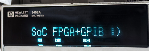
Image 8: HP 3458A displaying python code result
Here’s another app example, to setup and read data from HP 3458A multimeter
# xDevs.com Python 10V test for 3458A
# https://xdevs.com/guide/de1soc_gpib/
# https://xdevs.com/article/hp3458a_gpib/
# https://xdevs.com/fix/hp3458a/
import sys
import Gpib
import time

inst = Gpib.Gpib(0,3, timeout=60) # 3458A GPIB Address = 3
inst.clear()

#Setup HP 3458A
inst.write("PRESET NORM")
inst.write("OFORMAT ASCII")
inst.write("DCV 10")
inst.write("TARM HOLD")
inst.write("TRIG AUTO")
inst.write("NPLC 200")
inst.write("AZERO ON")
inst.write("LFILTER ON")
inst.write("NRDGS 1,AUTO")
inst.write("MEM OFF")
inst.write("END ALWAYS")
inst.write("NDIG 9")

cnt = 0
tread = 2
temp = 38.5
inst.write("TEMP?")
temp = float(inst.read())
reflevel = 10.0000000
ppm = 0

with open('10v_3458_nplc200_mm.csv', 'a') as o:
    o.write("date;hp3458a;level;temp;ppm_level;\r\n")
    o.close()

while cnt <= 10000000:
    cnt+=1
    with open('10v_3458_nplc200_mm_08451_opt002.csv', 'a') as o:
        tread = tread - 1
        if (tread == 0):
            tread = 20
            inst.write("TARM SGL,1")
            inst.write("TEMP?")
            temp = inst.read()
        inst.write("TARM SGL,1")
        data = inst.read()
        ppm = ((float(data) / reflevel)-1)*1E6
        inst.write("DISP OFF, \"%3.3f ppm\"" % float(ppm))
        time.sleep(1)
        print time.strftime("%d/%m/%Y-%H:%M:%S;") + ("[%8d]: %2.8f , dev %4.4f ppm, T:%3.1f" % (cnt, float(data),float(ppm),float(temp) ) )
        o.write (time.strftime("%d/%m/%Y-%H:%M:%S;") + ("%16.8f;%16.8f;%3.1f;%4.3f;\r\n" % (float(data),float(reflevel),float(temp),float(ppm) ) ))
        o.close()
Test output:
root@de1soclinux:/repo/3458# python ./test.py
14/11/2016-04:27:57;[       1]: 7.16374378 , dev -283625.6224 ppm, T:35.9
14/11/2016-04:28:05;[       2]: 7.16374354 , dev -283625.6455 ppm, T:35.9
14/11/2016-04:28:09;[       3]: 7.16374356 , dev -283625.6437 ppm, T:35.9
14/11/2016-04:28:14;[       4]: 7.16374372 , dev -283625.6277 ppm, T:35.9
14/11/2016-04:28:18;[       5]: 7.16374358 , dev -283625.6420 ppm, T:35.9
14/11/2016-04:28:22;[       6]: 7.16374381 , dev -283625.6188 ppm, T:35.9
14/11/2016-04:28:27;[       7]: 7.16374365 , dev -283625.6348 ppm, T:35.9
14/11/2016-04:28:31;[       8]: 7.16374330 , dev -283625.6704 ppm, T:35.9
It works well. :)
Additional interfaces, LXI via Python
One of our readers also mentioned possibility of using LXI-compatible instruments with Python as well.
To use this simple guideline can be followed. Create folder (for example /home/LXI).
mkdir /home/LXI
Enter directory and get SVN repository for python-vxi
svn checkout https://github.com/python-ivi/python-vxi11
Enter /home/LXI/python-vxi11/trunk directory
python setup.py install
Now python-vxi should be installed on your DE1-SoC platform
Here’s example python app to talk with VXI instrument:
import vxi11
instr =  vxi11.Instrument("192.168.0.8")
print(instr.ask("*IDN?"))
In case of correct installation and connection reply can be as below:
Keithley Instruments Inc., Model 2636B, 1234567, 3.2.1
More information is available on github for python-vxi11 or Alex Forencich’s site
He also had created python-usbtmc for Python USB commnication with instruments, so check it out.
If you have any comments and suggestions – feel free to join in comments!
Projects like this are born from passion and a desire to share how things work. Education is the foundation of a healthy society - especially important in today's volatile world. xDevs began as a personal project notepad in Kherson, Ukraine back in 2008 and has grown with support of passionate readers just like you. There are no (and never will be) any ads, sponsors or shareholders behind xDevs.com, just a commitment to inspire and help learning. If you are in a position to help others like us, please consider supporting xDevs.com’s home-country Ukraine in its defense of freedom to speak, freedom to live in peace and freedom to choose their way. You can use official site to support Ukraine – United24 or Help99. Every cent counts.
Modified: March 30, 2020, 6:08 p.m.