Motivation of this guide.
Dealing with electronic equipment manufactured decades ago have own special flёur to it. Back then we had documentation with nice service manuals, excellent schematics, assembly drawing diagrams, extensive theory of operation and troubleshooting methods. Today professionals and design engineers have to fight against corporate lawyers and business cartels to have legal right to repair equipment we own.
Article today is about a way to revive some old units with faulty display backlight to former glory. It takes huge amount of man-hours and grey-beards to develop advanced and high performance test instruments. Also it is not trivial to maintain equipment in good health, especially for that extended lifespan over 25+ years. Reason is rather generic – many components from the past often not available on the market today. This means difficult and time consuming workarounds and repairs with modern equivalents if any of the obsoleted parts go bad.
In this article we will look at finding replacement for key component of user interface such as graphical LCD screen. Back in the 90’s vacuum fluorescent displays were the king of the market for high end instrumentation. We can name just few well known examples – HP 3458A, Fluke 5700A, Datron 1281 or even daily bench meter like HP 34401A. LCD tech still was quite new and developing then. Here we will be patching up not just any instrument, but the crown jewel of the resistance metrology field – Measurements International 6010B 9½-digit DCC bridge. 6010B is a predecessor from 1997 of today’s modern Model 6010D improved version.
Metrology lab targeted bridge system like 6010 in 99.9% of target usage cases is controlled remotely via control program over GPIB bus. But in rare case when operator needs to run quick check or verify good connections to resistance standards user can find onboard LCD handy. However, here is a weak point in such case if factory-made backlight got faulty due to age of some older instruments.
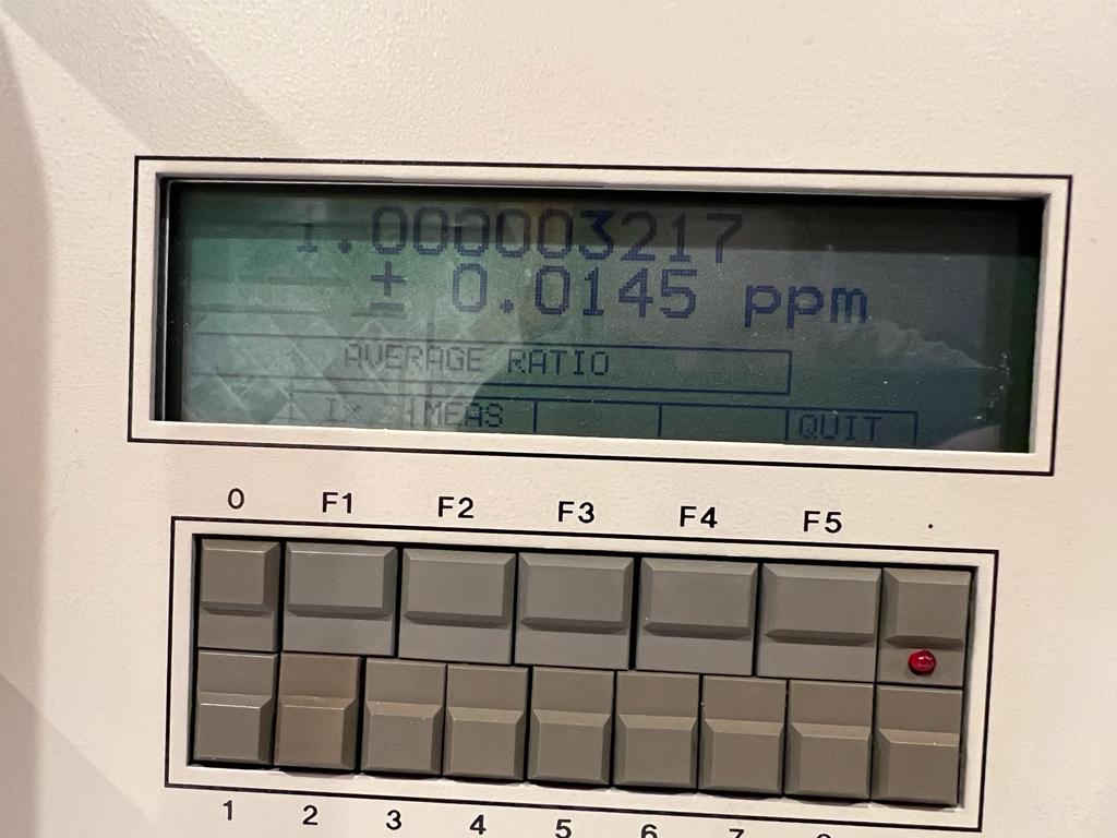
Image 1: MIL 6010B unit with dead backlight
For comparison here how it was looking before with original lamp backlight working properly, with original factory LCD:
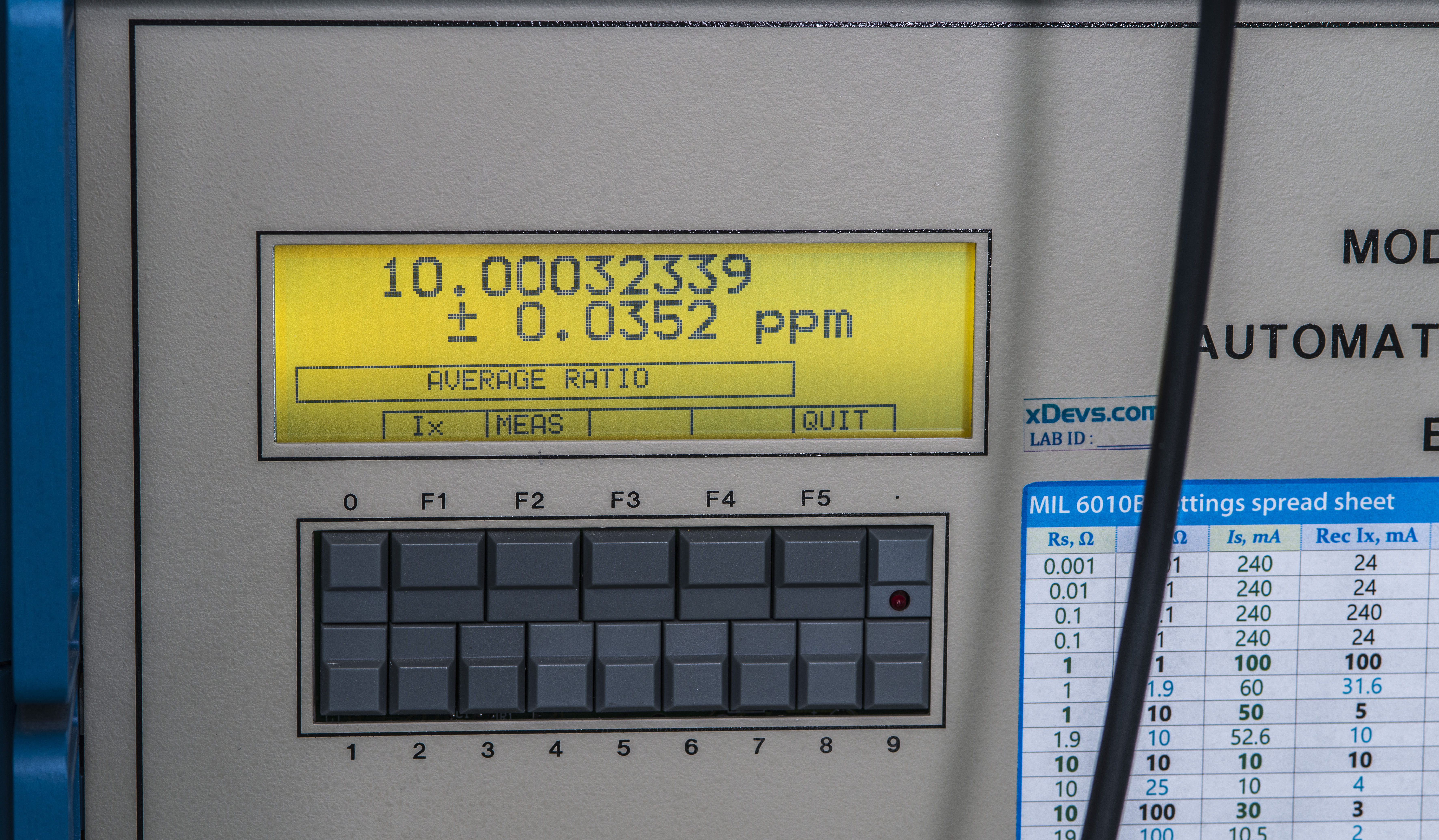
Image 2: MIL 6010B bridge with working original lamp backlight. Enhanced contrast.
Older 6010 bridges using miniature incandescent light bulb for providing backlight. This backlight is quite fragile and with 25-year old obsoleted instrument like 6010B chances for dead lamp or near failing one are high. It would be hard or next to impossible to find exact to-spec replacement for original bulb today. But not all is lost and we can rectify the situation with new LED-backlit high contrast display instead.
This would give more user enjoyment out of older but still perfectly capable instruments. Keep in mind that LCD replacement procedure and steps in this guide are shown only as simple example on what can be done. It is not the only possible solution, but perhaps rather easy one.
Disclaimer
Redistribution and use of materials in this article or any files referenced in it, in source and binary forms, with or without modification, are permitted provided that the following conditions are met:
- Redistribution of article must retain the above copyright notice, this list of conditions, link to this page (https://xdevs.com/guide/mi6010_lcdmod/) and the following disclaimer.
- Redistribution of files in binary form must reproduce the above copyright notice, this list of conditions, link to this page (https://xdevs.com/guide/mi6010_lcdmod/), and the following disclaimer in the documentation and/or other materials provided with the distribution, for example Readme file.
All information posted here is hosted just for education purposes and provided AS IS. In no event shall the author, this site, or any other party, including Measurements International Limited be liable for any special, direct, indirect, or consequential damages or any damages whatsoever resulting from loss of use, data or profits, whether in an action of contract, negligence or other tortuous action, arising out of or in connection with the use or performance of information published here.
If you do not agree with risks involved, do not perform the any modifications to any of your hardware.
Old lamp-backlit LCD assembly
MIL 6010B build is very modular and mechanically well designed. Front panel MIL 6010B can be detached from chassis by removing four screws on the sides. 6010 units have LCD, backlight and keypad are mounted on front panel metalwork.
Original display was manufactured by Japanese manufacturer AND, Model AND711AST-30. This is 240 × 64 pixel dot matrix STN graphical display. Display is based around T6963C controller and has +5 VDC standard parallel I/O interface.
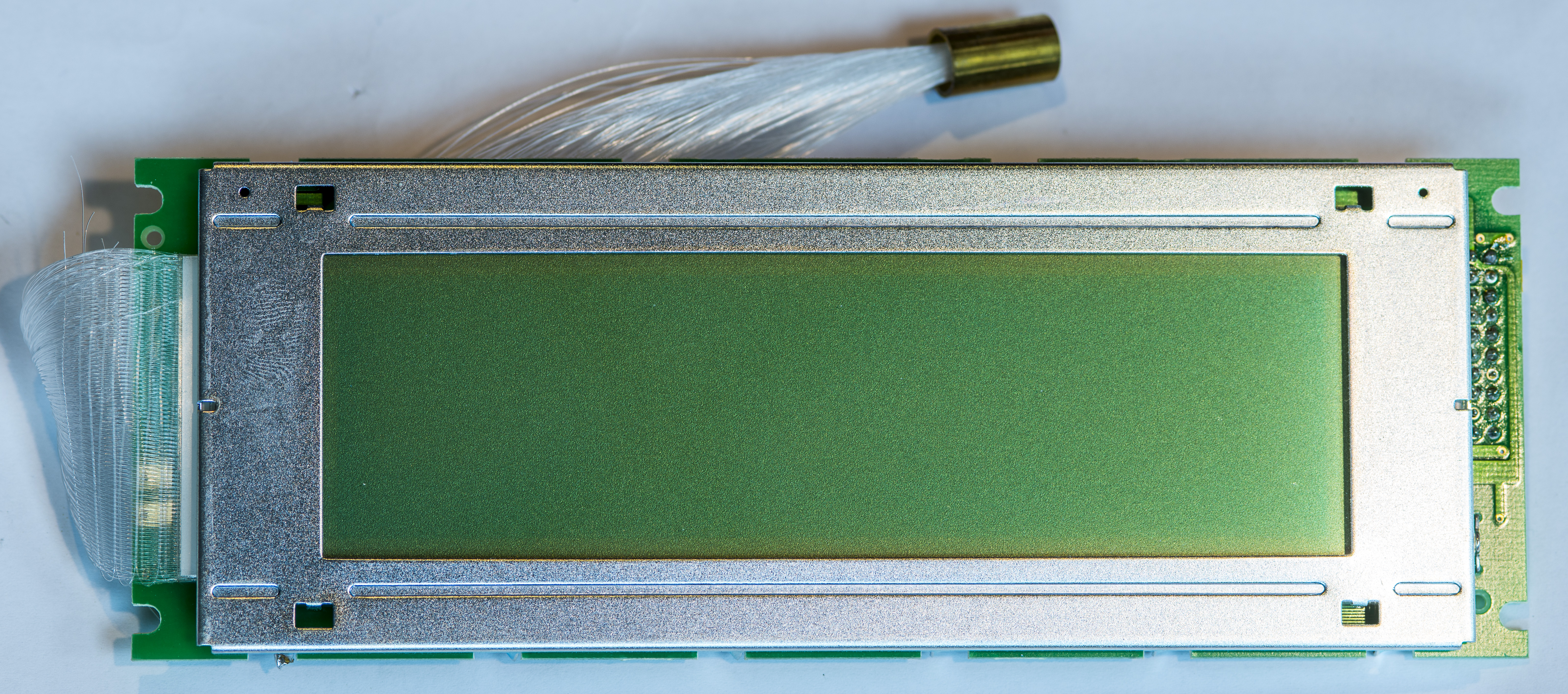
Image 3: Original AND graphical display, front side
This display does not have integrated backlight but has optional special option for electroluminescent backlight (-EO suffix). Measurements International didn’t go for electrically noisy high-voltage electroluminescent backlight. Instead they went for linear low voltage incandescent bulb in aluminum reflective/heatsink focused on very cool looking multi-fiber optical cable to spread light into LCD light diffuser.
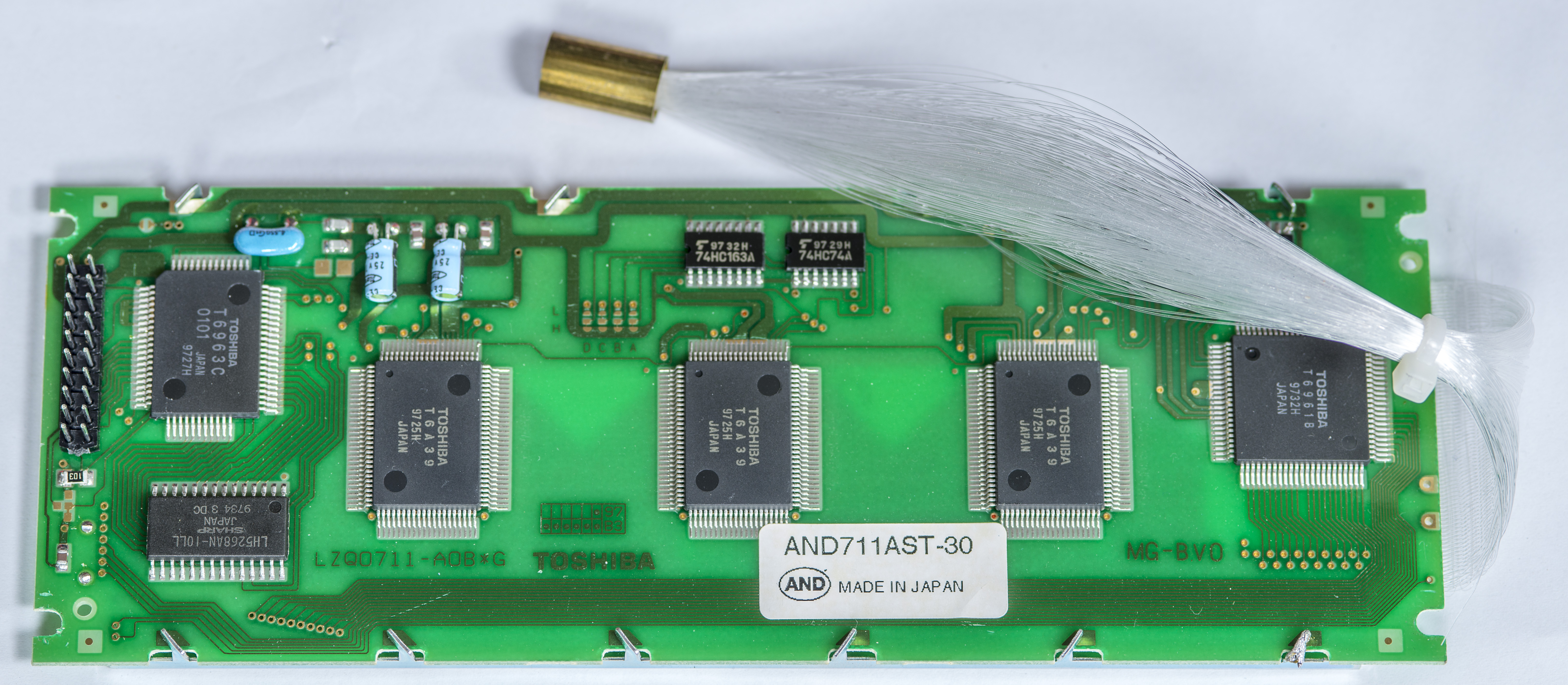
Image 4: Original AND graphical display, back side
Fiber is spread into diffuser plate inside LCD in a woven pattern. It is glued together at display entry and reinforced sideways by unused fibers.
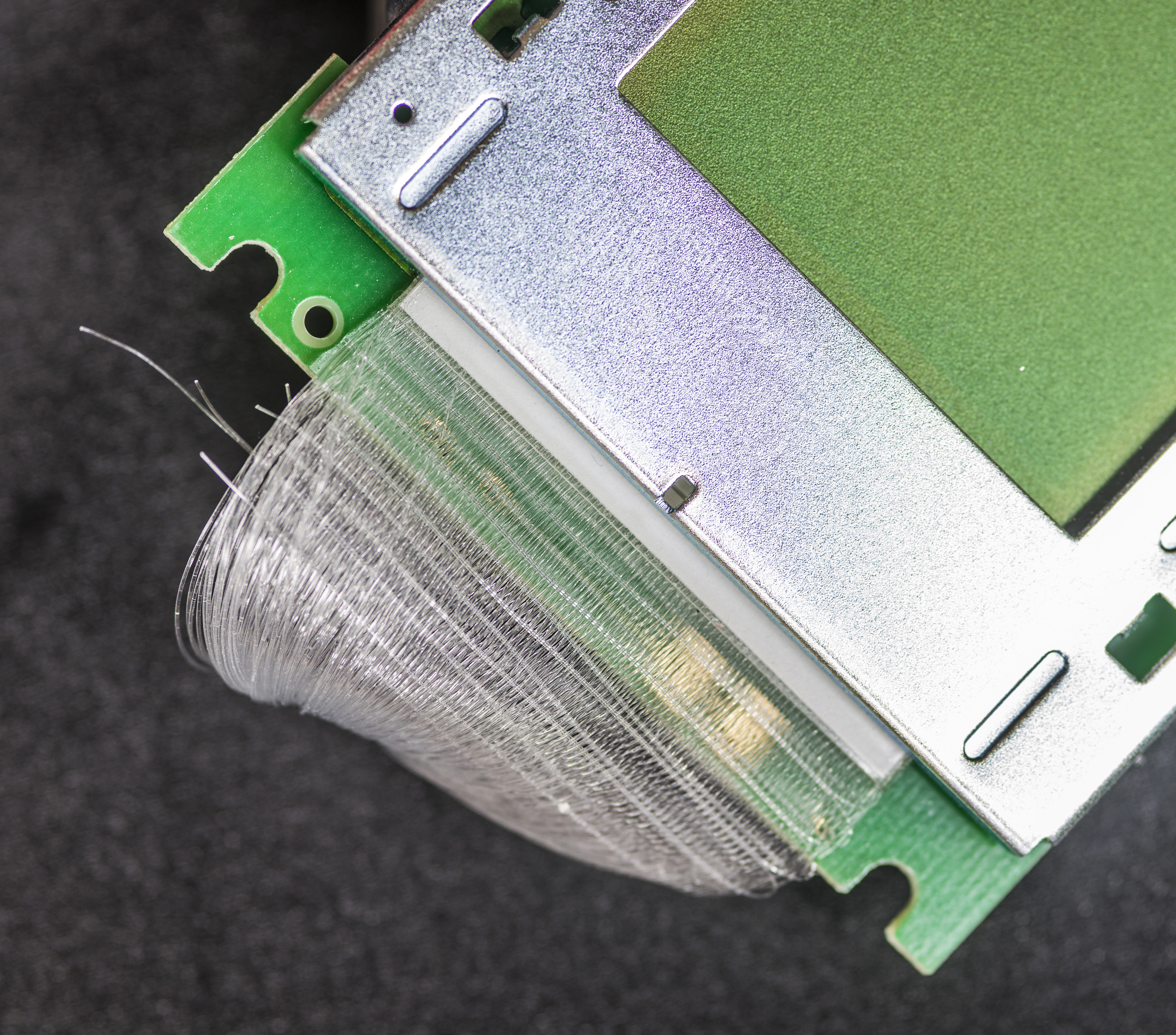
Image 5: Fiber cable backlight entry at LCD module
Optical cable receiver end is fixed into tight bunch with white cement and mounted in brass tube. This tube is further mounted into lamp assembly carrier (it’s shown on Image 13).
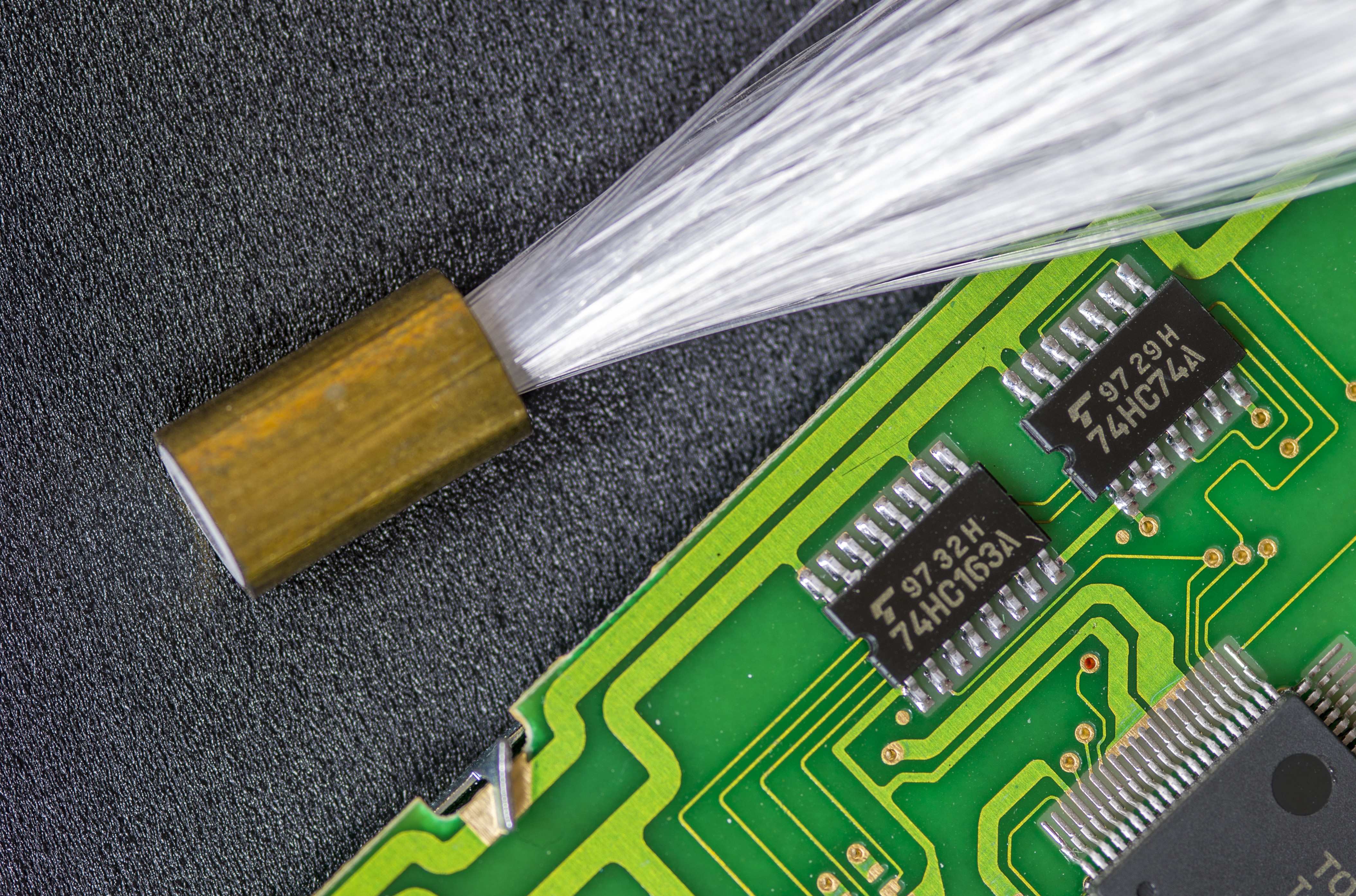
Image 6: Optical cable input adapter
Each strand on fiber cable is edged and polished to perfectly flat surface to have good light transmission from light source to backlight module in LCD.

Image 7: Polished fiber strands edge
Lamp is driven with power from separate low voltage winding. Lamp loaded voltage is around 4.2 VAC. Measured current with working lab shown on oscilloscope capture Image 8.
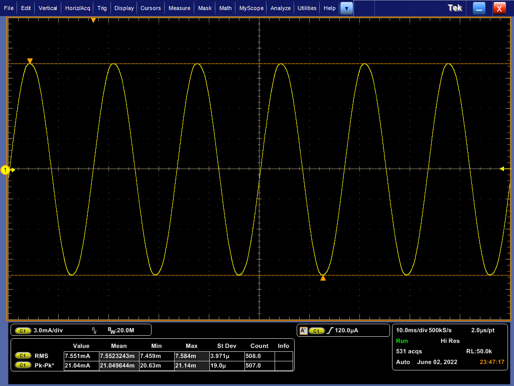
Image 8: Current waveform across working lamp in 6010B
Despite reasonably low power that lamp use it gets to blazing hot temperatures. Infrared camera thermograph with temperature markers are shown below. Hottest center element is actually glass infrared filter to prevent lamp heat reaching fragile fiber-optic cable. It is transparent to visible light allowing very warm yellowish backlight to operate. Temperatures of excess +195 °C were present close to lamp.
Epoxy reflector body get as hot as +97 °C (but it’s hard to see on infrared image due to high aluminum reflectivity).
Fiber optical cable edge have typical temperature around +49 °C and fiber exit at +34 °C. This whole assembly is quite a hot source, but it is located far from any precision metrology circuits or boards, so it does not affect actual DCC operation in any bad way.
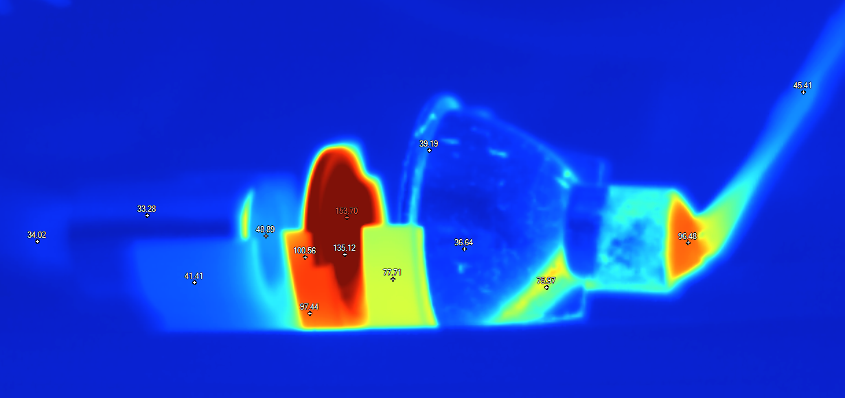
Image 9: Thermal image of lamp assembly during operation
New high-contrast negative polarization LCD
We spent some time trying different LEDs to act as a light source for backlight as lamp replacement. But brightness of used LED was either too low or light source required some non-standard chip-type LED that is quite difficult to position into perfect spot in reflector body to aim focused light on fiber input.
Plan B route was selected with replacement of whole LCD module assembly with modern. Replacement LCD has LED backlight already integrated in module.
To match style of light-blue Measurements International instruments and latest 6010D negative white display used. We got few mechanically and most important, electrically compatible RA6963-based EastRising ERM24064DNS-1 LCDs. These modules available for inexpensive $28 USD and have very close dimensions to AND original LCD used by factory.
ERM24064-1 LCD module datasheet, rev 1.0
ERM24064-1 LCD RA6963 controller datasheet, rev 1.3
ERM24064-1 LCD interfacing document, rev 1.0
ERM24064-1 LCD Demo code for 8-bit 8080 interface
Detailed specifications of this replacement panel:
| Manufacturer | EastRising |
| Display Format | 240×64 Dots |
| Interface | 8080 8-bit Parallel |
| IC or Equivalent | RA6963 |
| Appearance | White on Black |
| Diagonal Size | 5.2” |
| Connection | pin header position |
| Outline Dimension | 180.0(W)x65.0(H)x12.6(T)mm |
| Visual Area | 132.60×39.00mm |
| Active Area | 127.15(W)x33.87(H) |
| Display Type | FFSTN-LCD Black |
| Viewing Direction | 6:00 |
| Backlight Color | White Color |
| Backlight Current (Typ) | 120mA |
| Power Supply(Typ) | +5 VDC |
| Supply Current for LCM | 20mA |
| Continuity Supply | Long term continuity supply for this product no less than 10 years since 2015 |
Table 1: Specifications of EastRising ERM24064-1 LCD
There are multiple color/backlight variants of this display, so if you don’t want negative white on black, take a look on alternative colors as well.
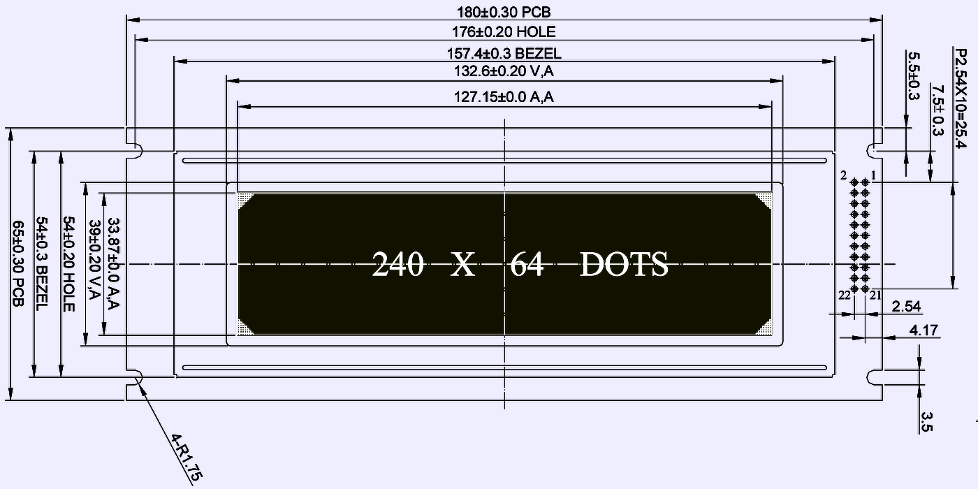
New module have very similar mechanical dimensions, but does not match old display perfectly. It need small amount of alignment in position for good centering. I did not want to modify original mounts or frame thus can live with few millimeters off ideal position.
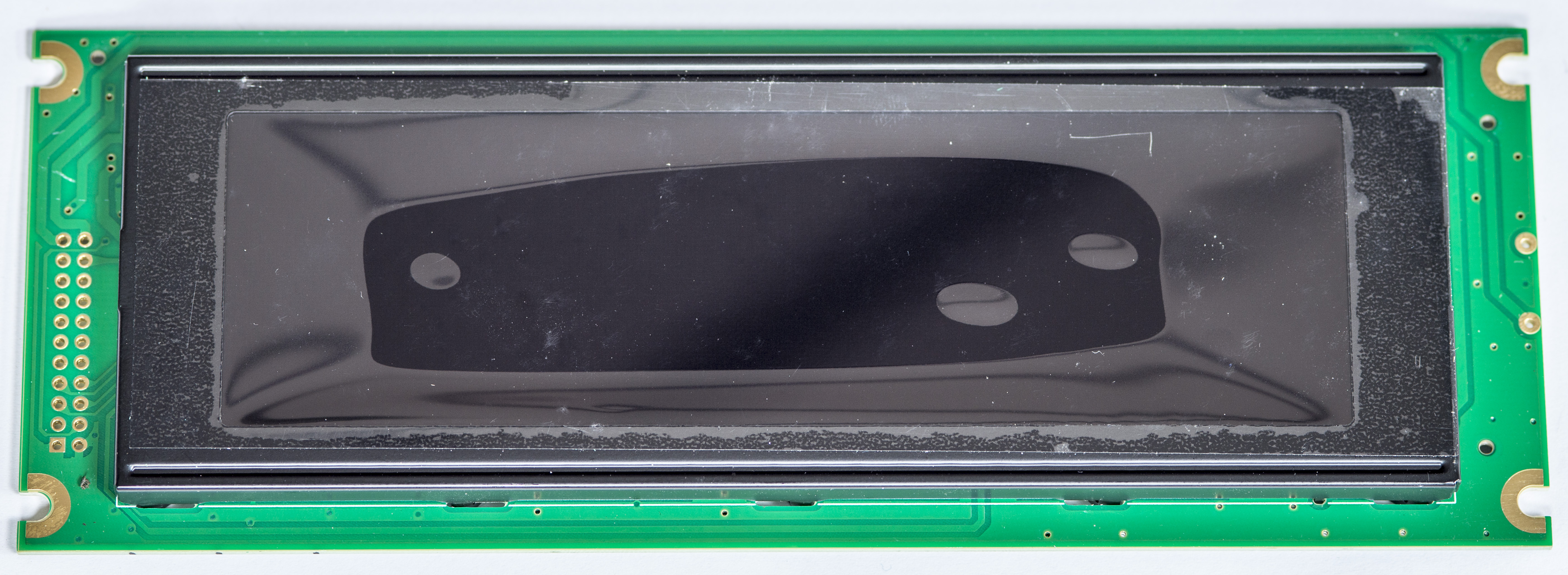
Image 10: New LCD , front side. Protective film is not removed
Displays I’ve got did not have connector populated. It is just standard 2.54mm pitch dual row 22-pin header, so any standard connector fits fine there.
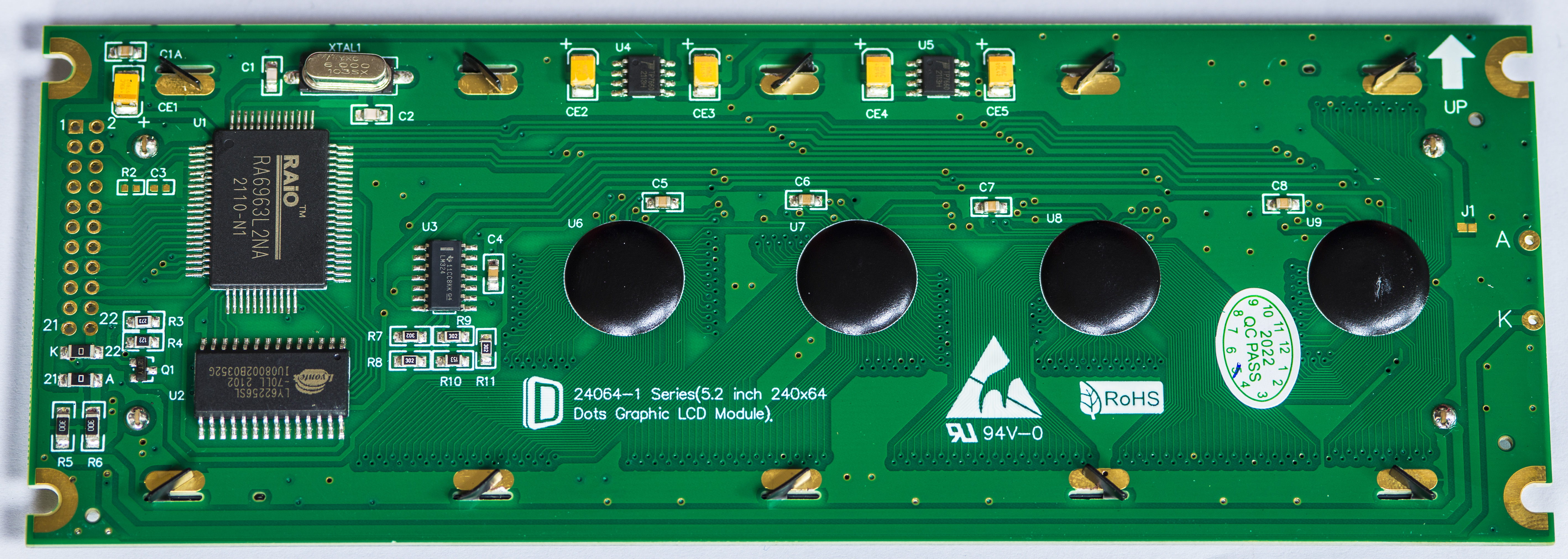
Image 11: New LCD, back side
MIL 6010 use 20-conductor flat ribbon cable to interface with LCD. Pins 21 and 22 used for backlight power. These need to be connected to +5V power source by user.
LCD modification steps to operate with MIL 6010B.
There are two modifications required to enable EastRising ERM24064DNS-1 operation in MIL 6010B bridge.
First we need to provide power to white LED backlight. Power measurement on my display sample revealed current draw around +110 mADC at supplied +5.00 VDC.
This is in line with datasheet specification, but I feel like bit smaller backlight power might be actually better. Jumping ahead, 6010B with new display is brightest instrument in the lab at night now. :)
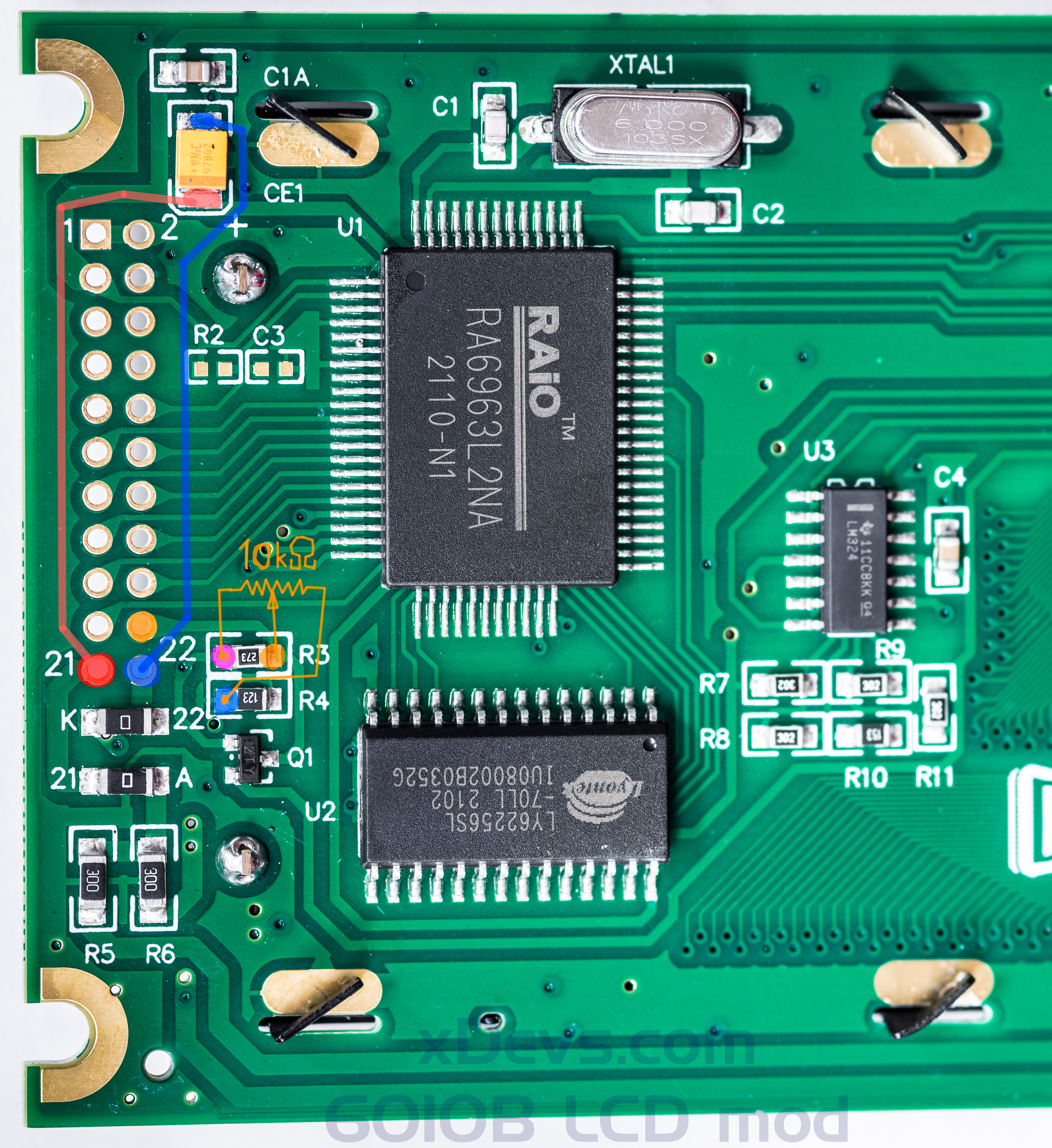
Image 12: Modifications for backlight power and LCD contrast
For backlight I’ve just jump-wired pin 21 to +5V positive terminal of input power tantalum capacitor CE1. And backlight cathode from pin 22 connected to negative terminal of the same capacitor. This supplied +5VDC across integrated LED backlight just fine.
Next modification is LCD contrast adjustment. Measurements International 6010B bridge does not allow user programmable LCD contrast change. We have to do it the hardware way. Contrast is controlled by bias from small negative supply and simple R3/R4 divider network. One way is to change values of R3 or R4 resistors on LCD PCB. Or alternative path, also recommended in interfacing document supplied with LCD is to connect multi-turn 10 kΩ trim potentiometer between negative supply (pin 20, marked orange on Image 12) and ground (marked blue on Image 12). Trim-pot was soldered directly to -15V and GND pads available at R3, R4 and all needed is good fixed contrast setting.
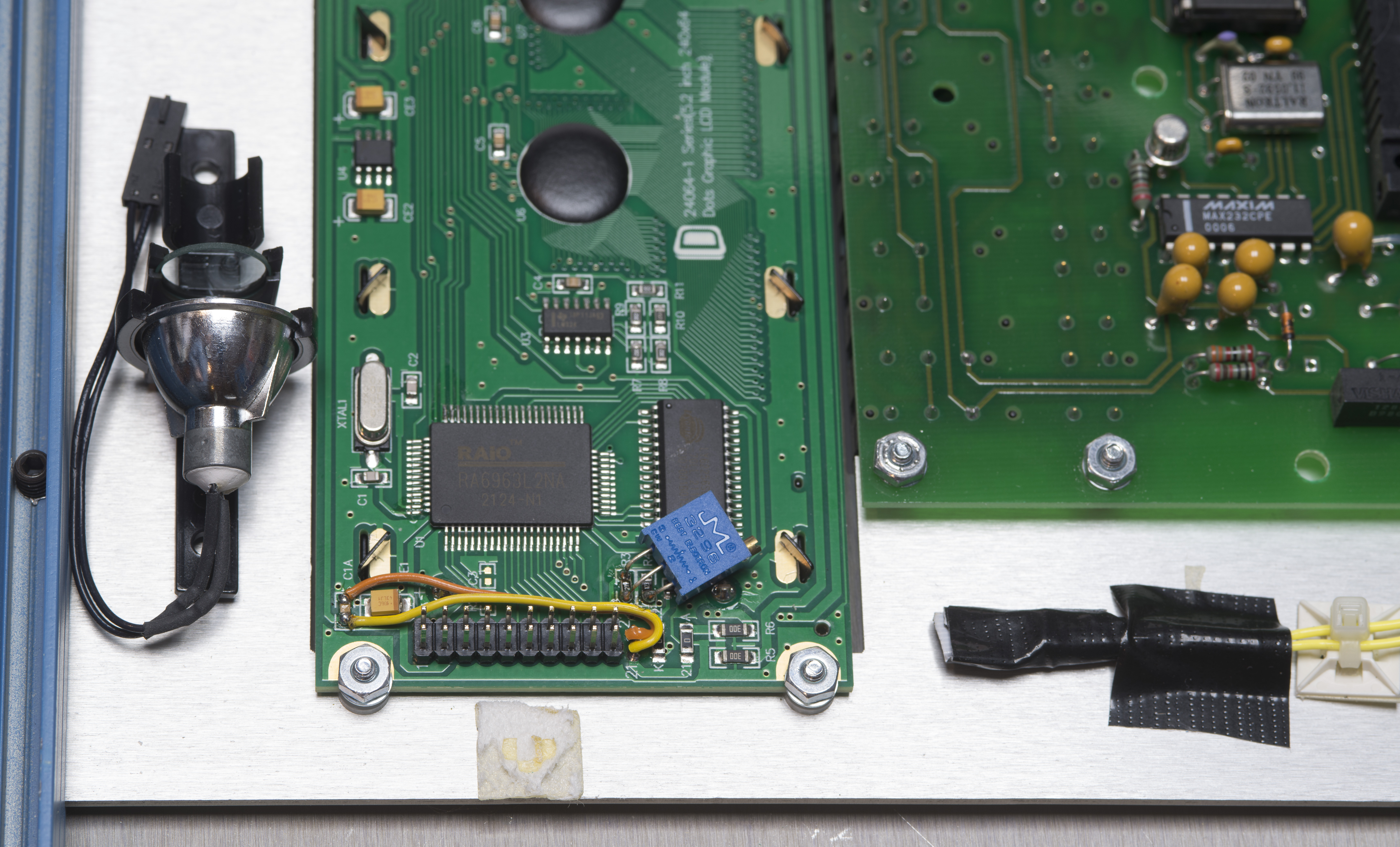
Image 13: LCD is modified and installed on front panel frame
After modifications on LCD completed, install it into unit. Make sure to insulate exposed 4.2 VAC pin header and wire used for old lamp power. I didn’t remove original lamp assembly and holder, you can still see it on Image 12.
It is not affecting anything now and just sits there unpowered, in case we ever want to revert MIL 6010B back to factory condition and original display.

Image 14: Everything connected and ready for testing
Make sure flat ribbon cable connected in proper orientation. Usually it is already previously bent from original display connection. Next is check everything, do a first power on. It is good time now to adjust contrast on display for desired viewing angles before closing everything together.
If everything works correctly, put front panel frame with new display back on 6010B frame and confirmed with success test, reassemble instrument back together.
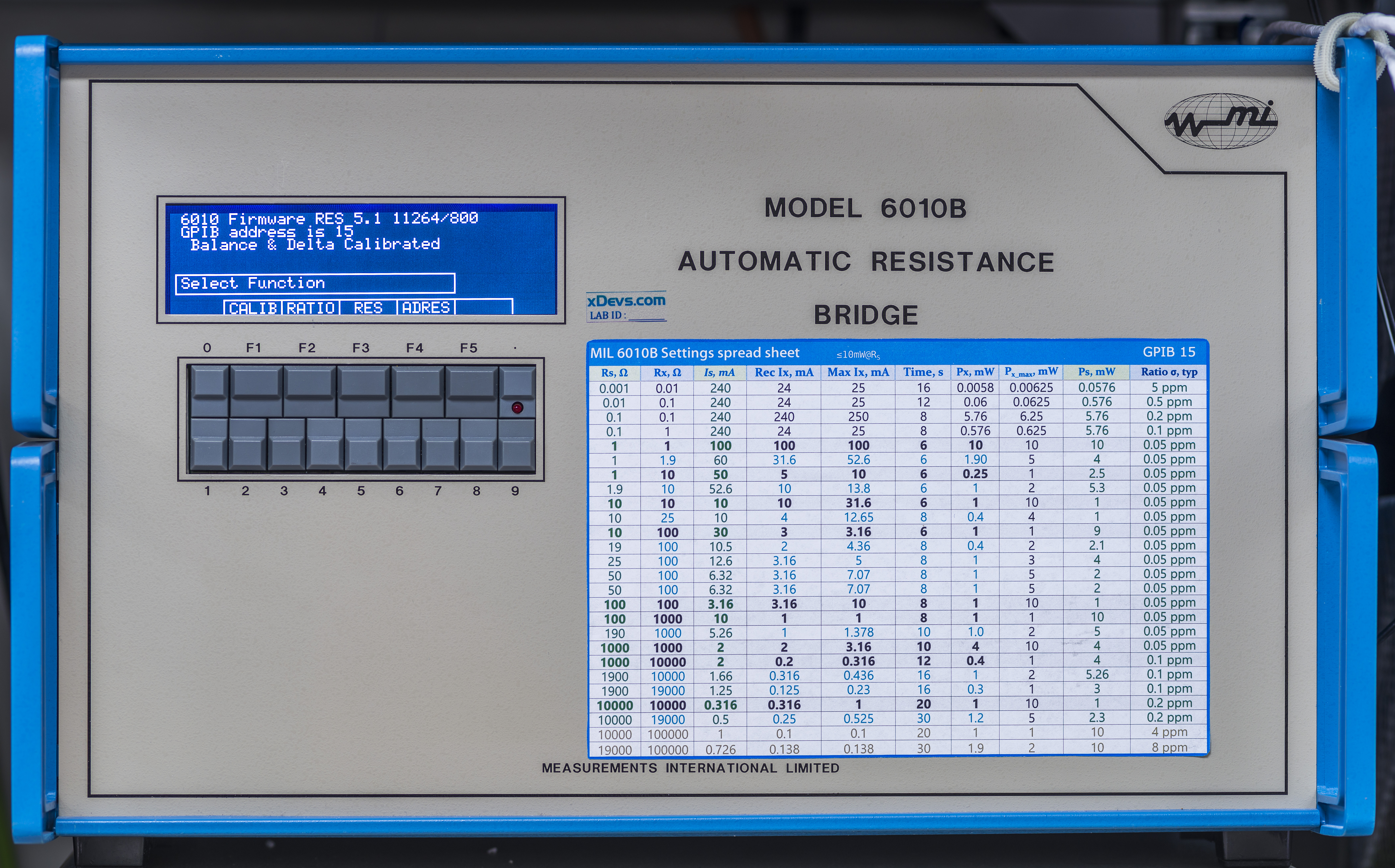
Image 15: Boot sequence information for 6010B with new LCD
Display is now looks in same style as handles and body of the Measurements International bridge. Very happy with contrast as well.
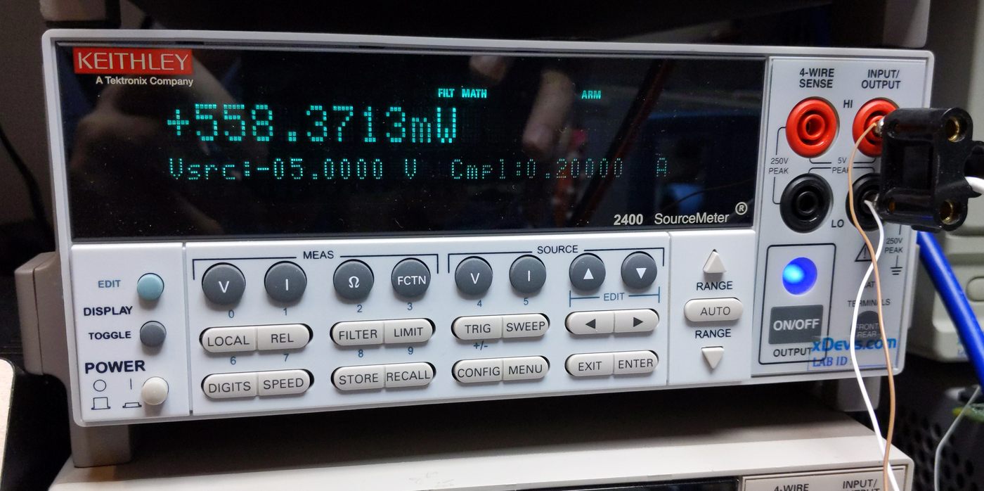
Setup some benchmark tests to verify performance of resistance transfers after reassembly too. Since we did not alter anything on analog side of the bridge, there should not be any effects on bridge performance.

Image 16: First power on and initial resistance transfer settings
This is it, now we can enjoy measurements.

Image 17: Happy bridge, happy resistance metrology!
Conclusion and summary
Such LCD replacement was easy and quick improvement of expensive and rare instrument. Hopefully this brings an example on how obsolete old parts can be replaced with modern technology, bringing second life to instruments we all love.
This article and many other resistance-related projects would not be possible without excellent instruments from Measurements International and their decades-proven top class calibration services to world-wide electrical metrology. Special thank you goes also to Igor, Tom and Todd for fruitful projects ideas, excellent support and friendship. You guys are great! :)
Discussion about this article and related stuff is welcome in comment section or at our own IRC chat server: irc.xdevs.com (standard port 6667, channel: #xDevs.com). Web-interface for access mirrored on this page.
Projects like this are born from passion and a desire to share how things work. Education is the foundation of a healthy society - especially important in today's volatile world. xDevs began as a personal project notepad in Kherson, Ukraine back in 2008 and has grown with support of passionate readers just like you. There are no (and never will be) any ads, sponsors or shareholders behind xDevs.com, just a commitment to inspire and help learning. If you are in a position to help others like us, please consider supporting xDevs.com’s home-country Ukraine in its defense of freedom to speak, freedom to live in peace and freedom to choose their way. You can use official site to support Ukraine – United24 or Help99. Every cent counts.
Modified: Feb. 1, 2023, 12:50 a.m.