- Motivation
- Disclaimer
- Schematics
- Design and physical layout
- Flexible PCB variant from PCBWay as manufactured
- Bill of materials and costs
- Python code library and example applications
- Conclusion and project summary
Motivation
Need more sensors! The crux of this project is to have a cheap and flexible way to measure various temperatures across devices under tests, resistance and voltage standards and internal hot spots on PCBs. One could utilize ready to go thermocouples and relay scanner cards, such as Keithley 2001TC-SCAN but this makes a complicated and expensive solution that depends on specific instrument. Thermocouples also have rather poor absolute accuracy, making it difficult to maintain and calibrate such a setup.
Temperature range for many voltage and resistance devices often pretty narrow, from +18 °C to +28 °C. Sure, for critical applications we have nice calibrated thermistors and platinum resistance thermometers, but they are again quite expensive and require dedicated instrumentation to digitize. One of modern options are semiconductor sensors with digital interface such as Texas Instruments TMP11X series. They are very small, affordable and have pretty good specification for absolute accuracy. Resolution also sufficient to detect temperature change as small as 7.8 mK.
Disclaimer
Redistribution and use of this article, any part of it or any images or files referenced in it, in source and binary forms, with or without modification, are permitted provided that the following conditions are met:
- Redistributions of article must retain the above copyright notice, this list of conditions, link to this page (https://xdevs.com/guide/xth/) and the following disclaimer.
- Redistributions of files in binary form must reproduce the above copyright notice, this list of conditions, link to this page (https://xdevs.com/guide/xth/), and the following disclaimer in the documentation and/or other materials provided with the distribution, for example Readme file.
All information posted here is hosted just for education purposes and provided AS IS. In no event shall the author, xDevs.com site or any other 3rd party be liable for any special, direct, indirect, or consequential damages or any damages whatsoever resulting from loss of use, data or profits, whether in an action of contract, negligence or other tortuous action, arising out of or in connection with the use or performance of information published here.
If you are willing to contribute or add your experience regarding instrument repairs or provide extra information, you can do so following these simple instructions.
Certain commercial equipment, instruments, or materials are identified in this article to foster better understanding. Such identification does not imply recommendation or endorsement by the author or/and xDevs.com, nor does it imply that the materials or equipment identified are necessarily the best available for the purpose. Devices and components were not screened or conditioned prior to use in the electronic assembly, unless explicitly stated otherwise.
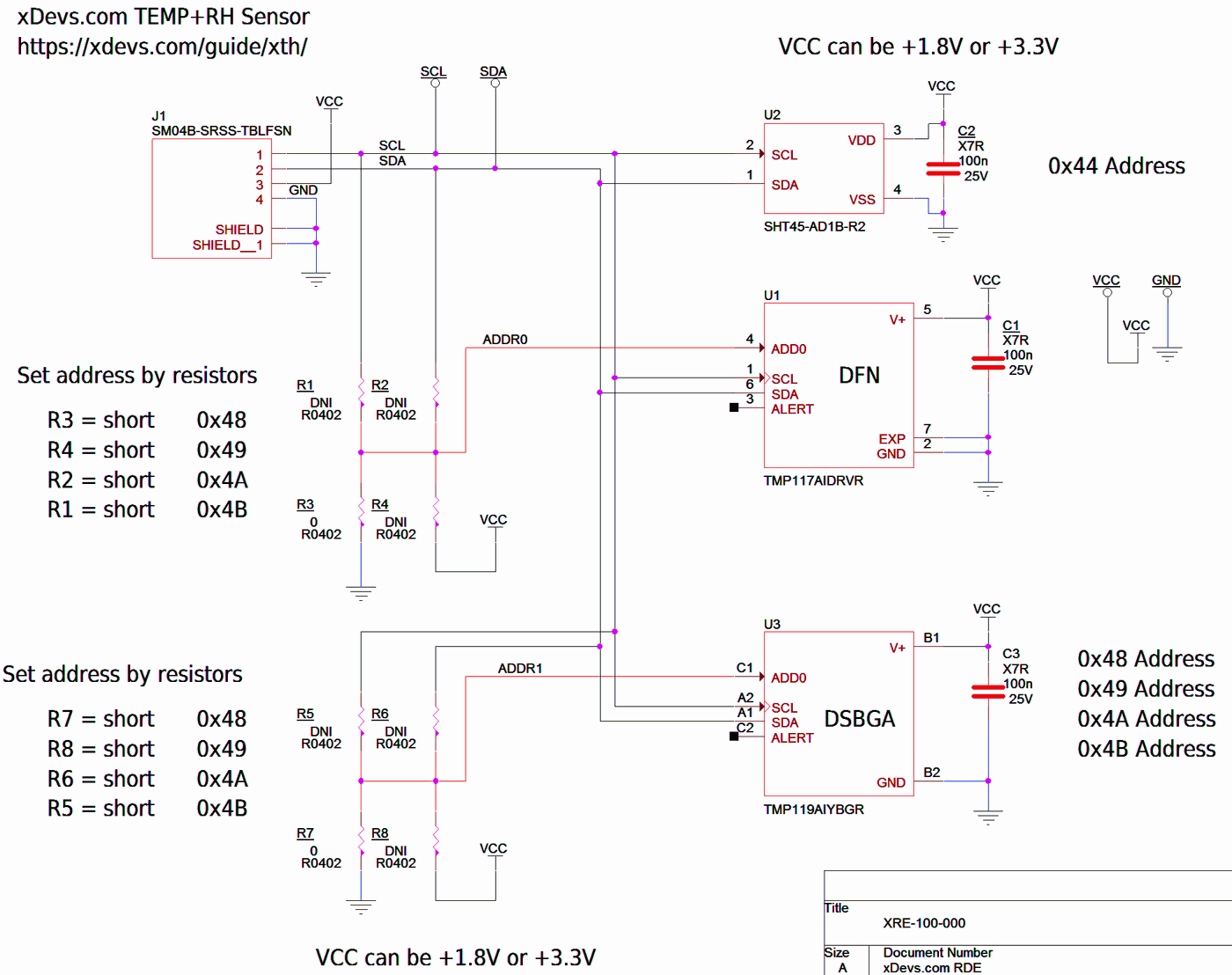
Schematics
It’s pretty trivial implementation of datasheet circuits for both of the Texas Instruments TMP11X sensors and Sensirion SHT4X. There are few decoupling capacitors in small 0402 size, footprint for fine wire or Qwiic connector, following their standard pin-out for I2C breakout with four wires.
Click on schematics drawing to open full resolution PDF-version.
Datasheets for the compatible sensors:
Texas Instruments TMP119 datasheet, January 2024
Texas Instruments TMP117 datasheet, March 2019
Texas Instruments TMP116, TMP116N datasheet, May 2019
Sensirion SHT4X, February 2023
Address setting resistor options are added for convenience for each U1 and U3 sensor. U2 relative humidity sensor does not allow changing address. This means that one I2C host can actually interface two sensors PCBs with both temperature TMP11X sensors populated on each of them, but only one can have unique SHT4X address. If user need to interface more thermometer boards, external non-transparent I2C bridge or multiplexer must be used to avoid bus addressing conflict.
There are no onboard pull-up resistors, the sensor board relies on resistors at the I2C host side of instead.
All sensors on this circuit can operate at lower +1.8 V power rail, but that might require external voltage level translator for I2C host if it’s operating on a different voltage. For tests later in this article we used Raspberry Pi 4 which has +3.3 V I2C I/O level.
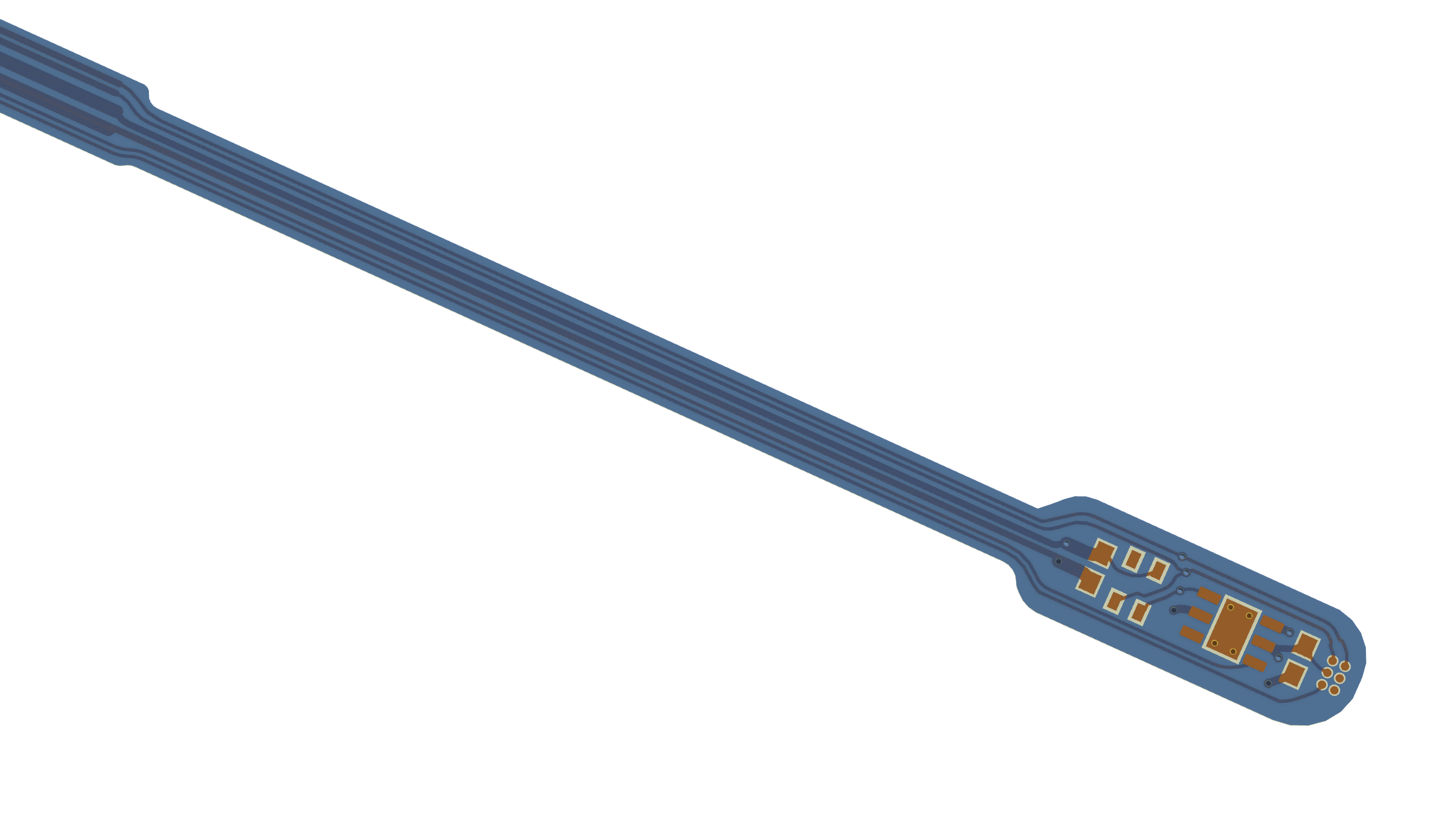
Design and physical layout
Main idea for physical implementation is to provide flexible and compact electrical pad with integrated sensing elements at some reasonable length away from interconnect. I wanted to try out brand new Texas Instruments TMP119 that promises quite remarkable ±80 mK accuracy in range from 0 °C to +45 °C with typical ± 30 mK spread. Unlike TMP117 and other older sensors in TMP11X series this model is available only in tiny 0.95 mm x 1.488 mm bare-die DSBGA6 package. So this meant adding DSBGA footprint on the PCB.
At the same time I did not want to limit the usability of the temperature sensor design only to people who are comfortable soldering small BGA (it’s not that hard actually, given access to good microscope and hot air). An alternative second temperature sensor WSON6 2 mm x 2 mm footprint was added as well. Pads are oversized and extended further from the package to allow easy access with a fine-tip soldering iron. Soldered connection to the exposed center pad of TMP117 sensor is not required for normal operation.
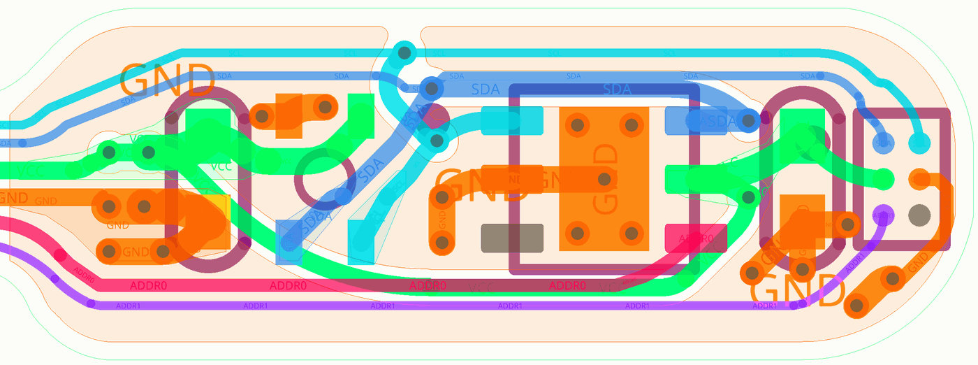
Two capacitors in 0402 size need to be placed next to sensor chips to provide local power decoupling.
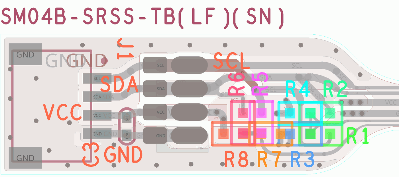
Resistors R1-R8 are provided to configure address for both U1 and U3 TMP11X devices. Available options are presented below. Make sure you don’t have conflicting (same) address on the I2C bus.
| Resistor | U1 TMP116/TMP117 | U3 TMP116/TMP117/TMP119 |
|---|---|---|
| R1 populated 0 Ω | 0×4B | set by R5-R8 |
| R2 populated 0 Ω | 0×4A | set by R5-R8 |
| R3 populated 0 Ω | 0×48 | set by R5-R8 |
| R4 populated 0 Ω | 0×49 | set by R5-R8 |
| R5 populated 0 Ω | set by R1-R4 | 0×4B |
| R6 populated 0 Ω | set by R1-R4 | 0×4A |
| R7 populated 0 Ω | set by R1-R4 | 0×48 |
| R8 populated 0 Ω | set by R1-R4 | 0×49 |
Relative humidity sensor SHT4X does not have external pin to configure address, so consult with datasheet for details about it’s configuration. By default SHT45 sensor will present itself on the bus with 0×44 address.
Do not populate multiple 0 Ω resistors related to same sensor, this would create short-circuit condition for the host and can damage components.
Either of the three sensors can be populated on the same sensor board, they operate independently when properly configured.
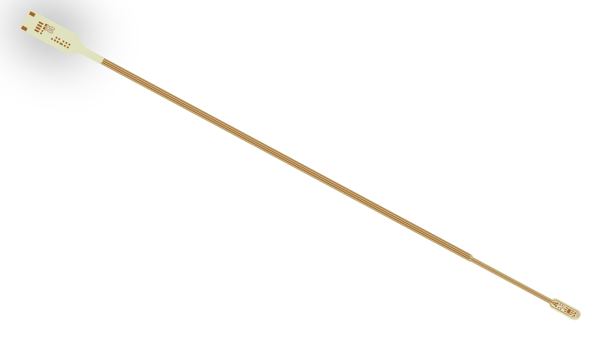
For a very fast thermal response and minimized thermal resistance between temperature sensor and measured surface/object the thickness of PCB substrate is minimized. The design can be manufactured both with usual but thin rigid FR4-board or flexible polyimide board with even thinner 0.08 mm substrate. Flex PCB is more fragile and bit harder to assemble but provides excellent flexibility and can reach tight spaces very nicely. While thin rigid FR4 can be more suitable for permanent position or more rugged application, more in line of traditional thermometer stick.
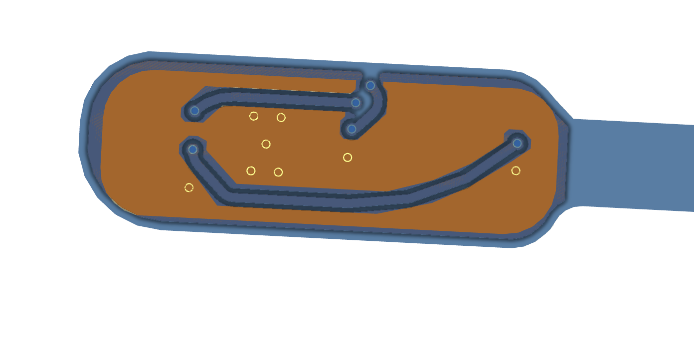
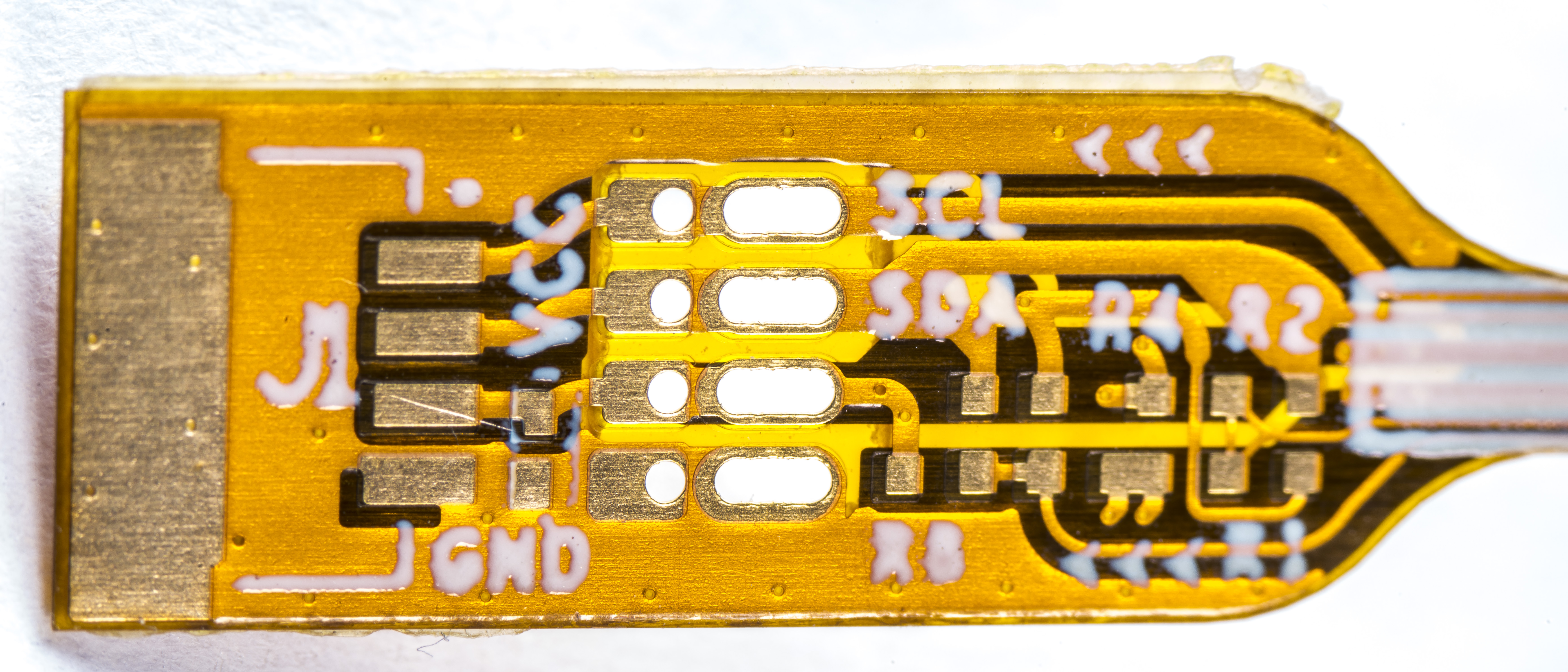
The back side of the PCB is exposed ground return potential to allow soldering to grounded metal plates/surfaces. Keep in mind that connecting this metal surface would galvanically connect GND potential with I2C host device (unless the galvanic isolation is used) and may provide a path for electrical noise propagation or create ground loop.
Online boards manufacturer PCBWay built Flex-PCB variant for me and it was just a bit over $130 USD delivered for 50 pcs of manufactured 2-layer 0.08 mm FPCBs. I’ve shared the design project on PCBWay for anyone willing to order their copy. Be sure to select proper flexible PCB or rigid FR4 PCB type, depending on what your preference is.
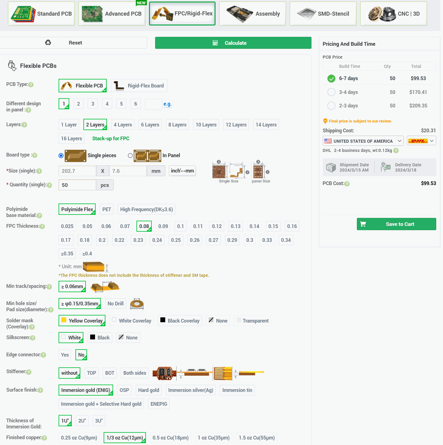
Flex-PCB dimension is 202.7 × 7.6 mm and it took just 13 days from submission of Gerber files to delivery of finished boards. I didn’t bother to order solder paste stencil since it’s just few components to populate and it’s trivial to do with soldering iron manually. I’ve add some solder to the BGA pads, added plenty of no-clean flux, placed tiny TMP119 sensor chip and TMP117 on respective positions and heated the board from the bottom side under with hot air set to +320 °C. Everything re-flowed and soldered just under a second.
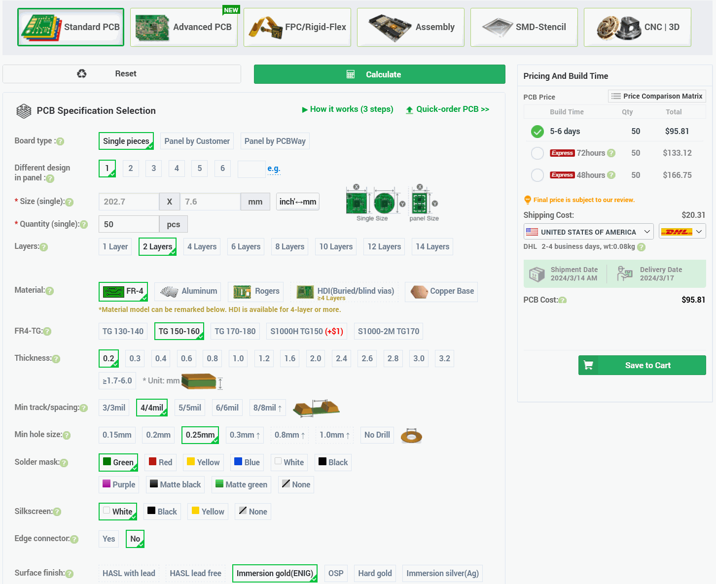
Rigid-FR4 version was priced about the same as FPCB, due to non-typical 0.2 mm thickness, small 0.25mm drill via diameter and more expensive ENIG plating option. I did not order rigid FR4 version. Prices above are for 50 pieces quantity. Most of the cost is in tooling and fabrication cost for such a small volume, so if one to order say 500 pcs the price per each board would drop by a lot. I just didn’t need that many of the temperature sensors yet ;-)

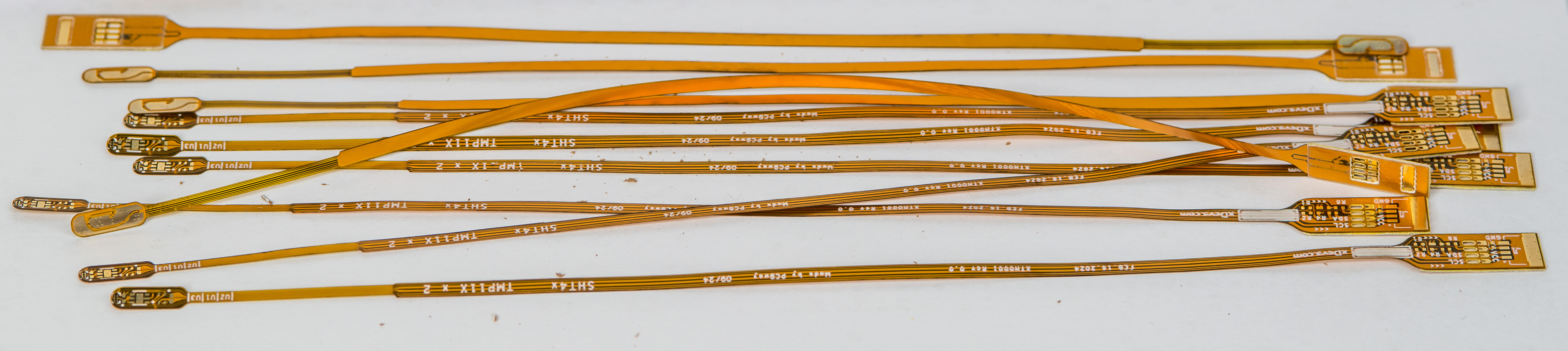
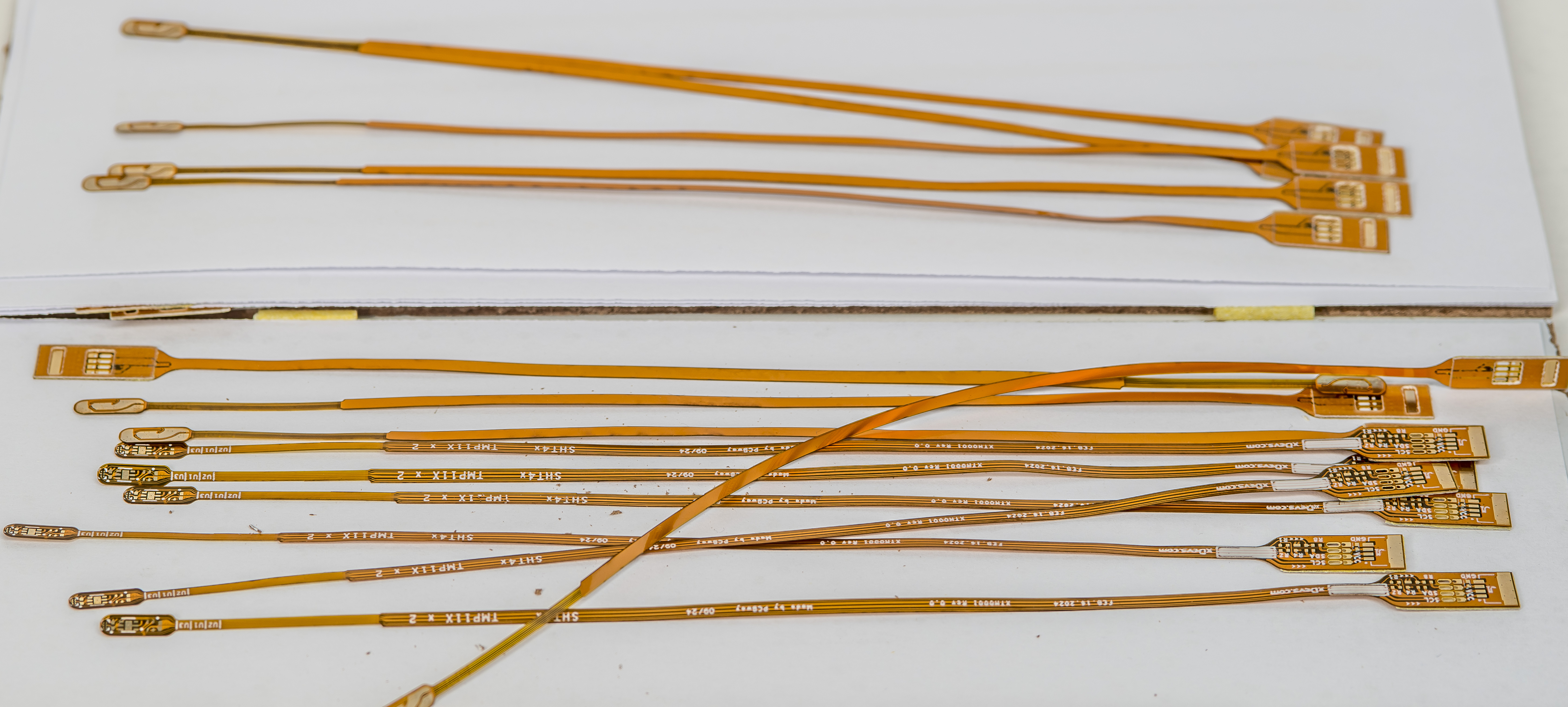
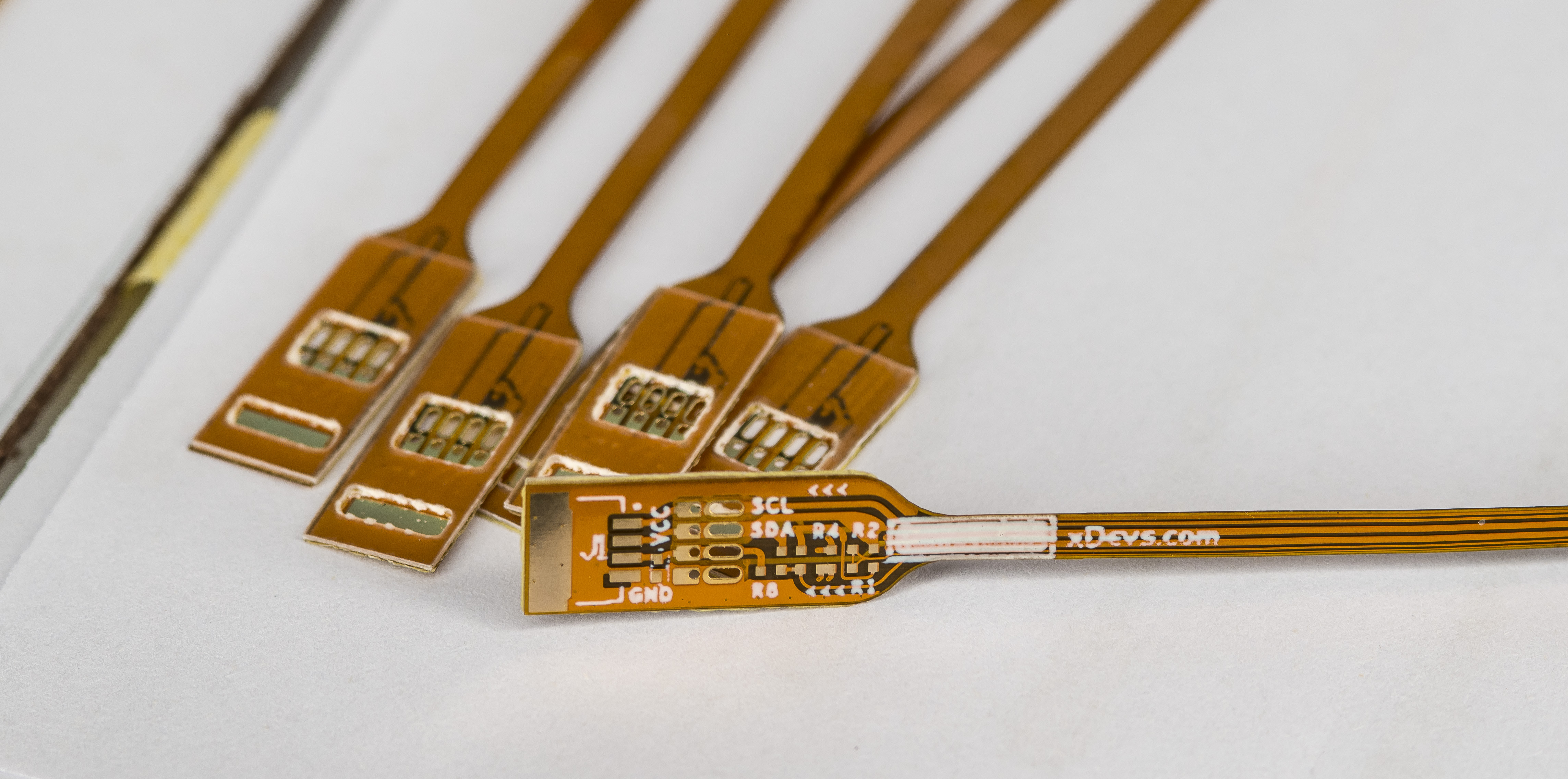
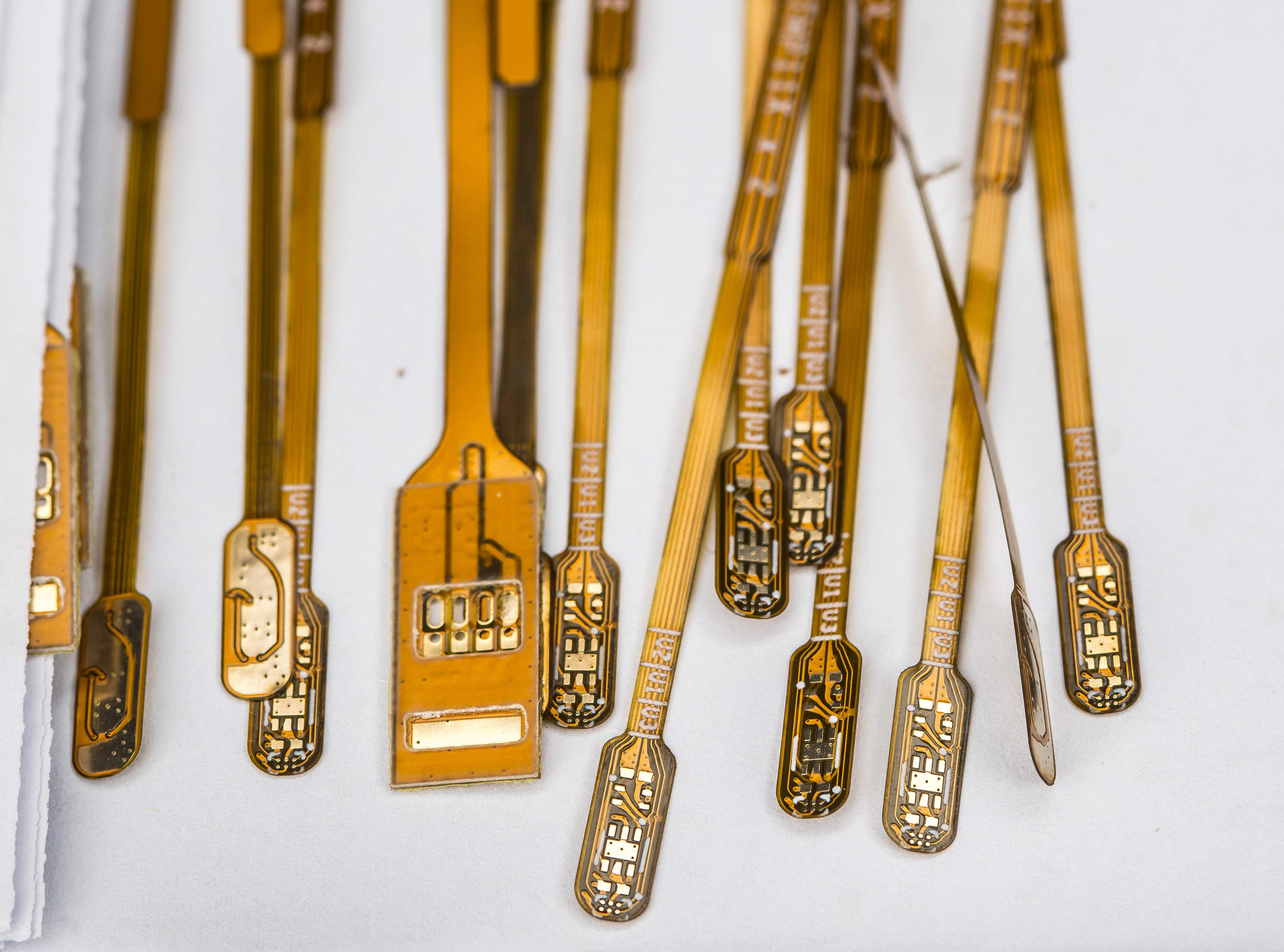
Flexible PCB variant from PCBWay as manufactured
Received boards are shown on photos below. Individual flexible boards were placed between paper layers to reduce amount of scratching and moving around during the transit. They were pretty decent and very flexible. Because of small width and narrow neck near the sensing tip island they can do full turn and change into any direction and orientation. Small mass also limits the thermal conduction from the sensor chips to the connecting cable/section.
Keep in mind that thin and flexible narrow board is more fragile than usual rigid FR4 PCB and avoid bending it with small radii. Such bends can cause copper traces cracks and damages.
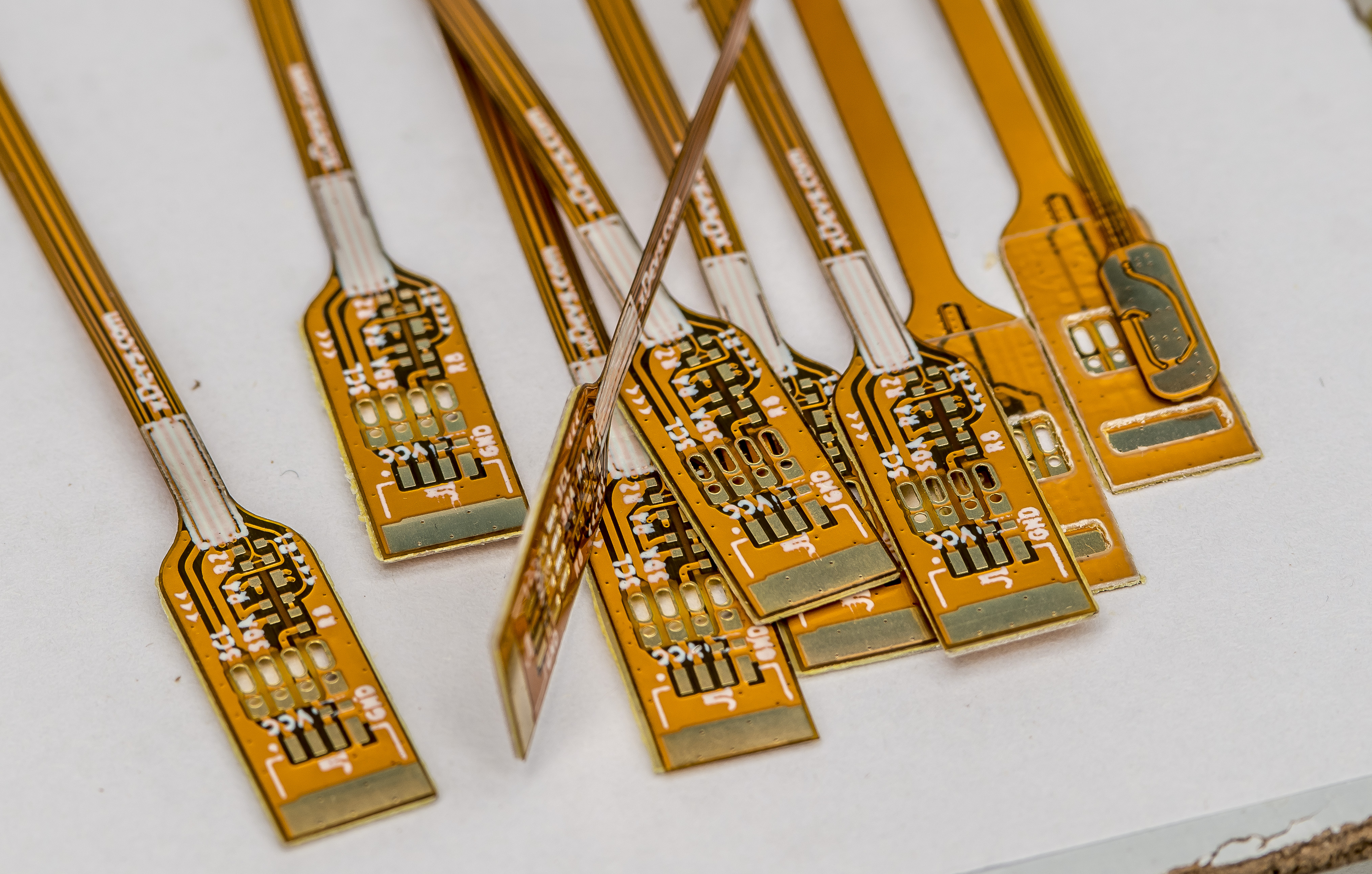
The silkscreen print could be bit better quality, but I can’t expect these low cost PCBs to have tiny features from high-resolution silkscreen. It’s totally suitable for my tests otherwise and final unit price was about USD $2.8 without components cost.
I’ve opted to have additional 0.4 mm thick FR4 stiffener on the back side in the connector area just to make that side a little more robust and mechanically rigid. Thin copper foil is quite soft and easy to bend, which might cause some problems in the long term use.
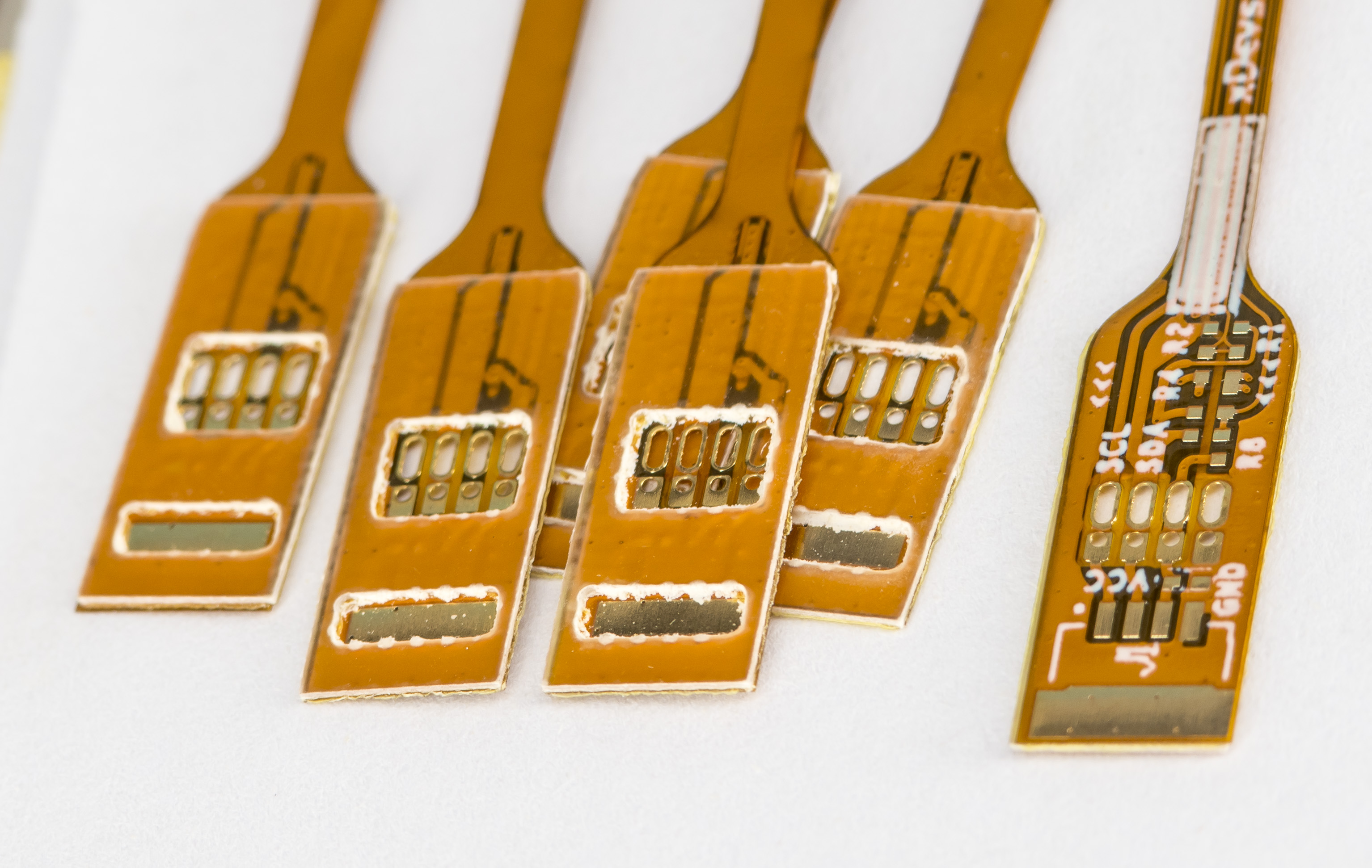
Stiffener substrate has cutout openings to access exposed copper metal on the bottom side of the flex PCB for soldering.
First prototype was assembled with just TMP117 and TMP119.
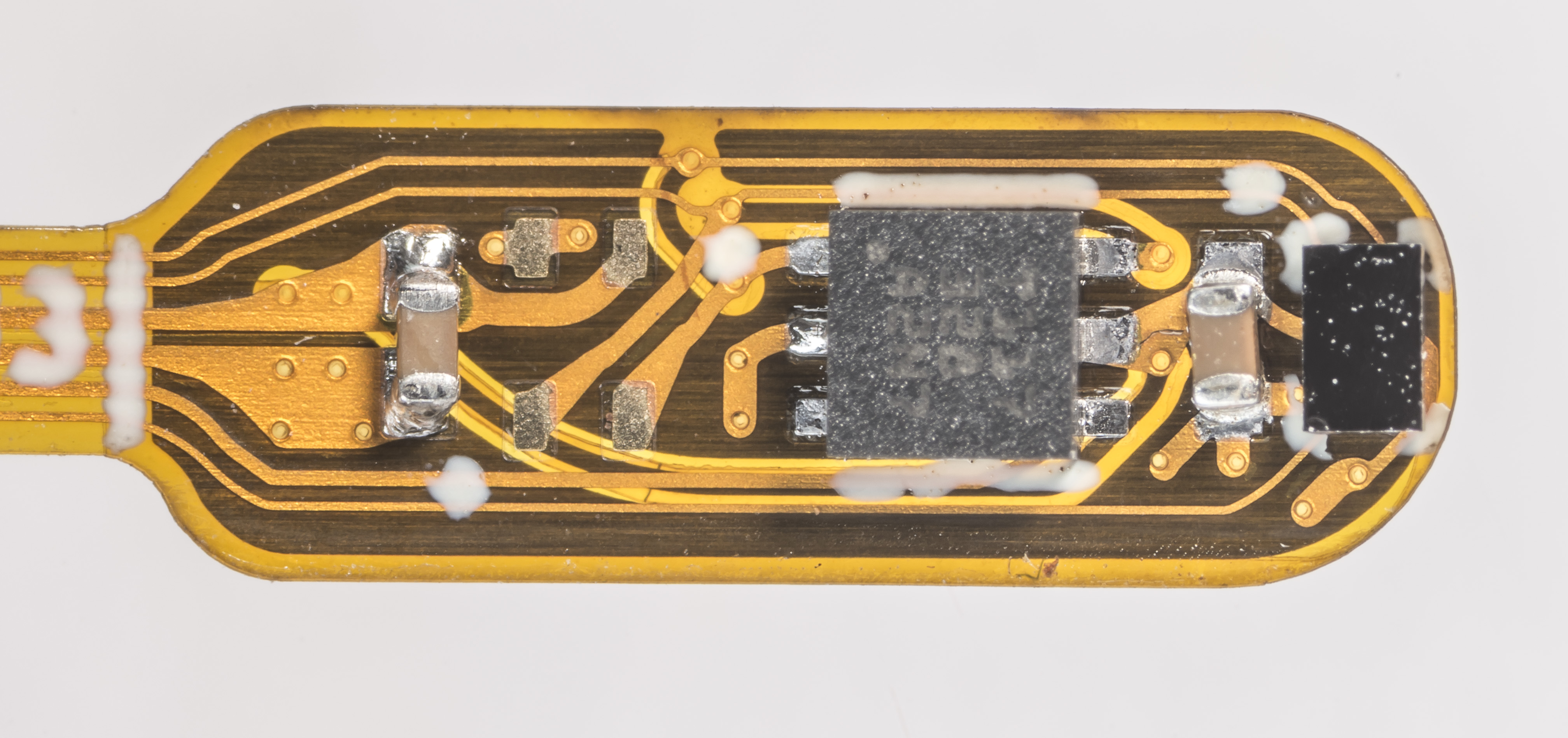
For first test I’ve populated R6 and R4 shorts, added some capacitors and installed TMP117 + TMP119, without SHT45 relative humidity sensor. Empty spot left unpopulated is for SHT45 sensor which I don’t have in stock at the moment to test.
This configuration assigned 0×49 address for TMP117 in WSON6 package and 0×4A for TMP119 in DSBGA6 package. When powered with +3.3 V from Keithley 2400 SMU for first test flex sensor board consumed around 180 µA with pulses about 400 µA. This is well in line of active conversion power specified by Texas Instruments.
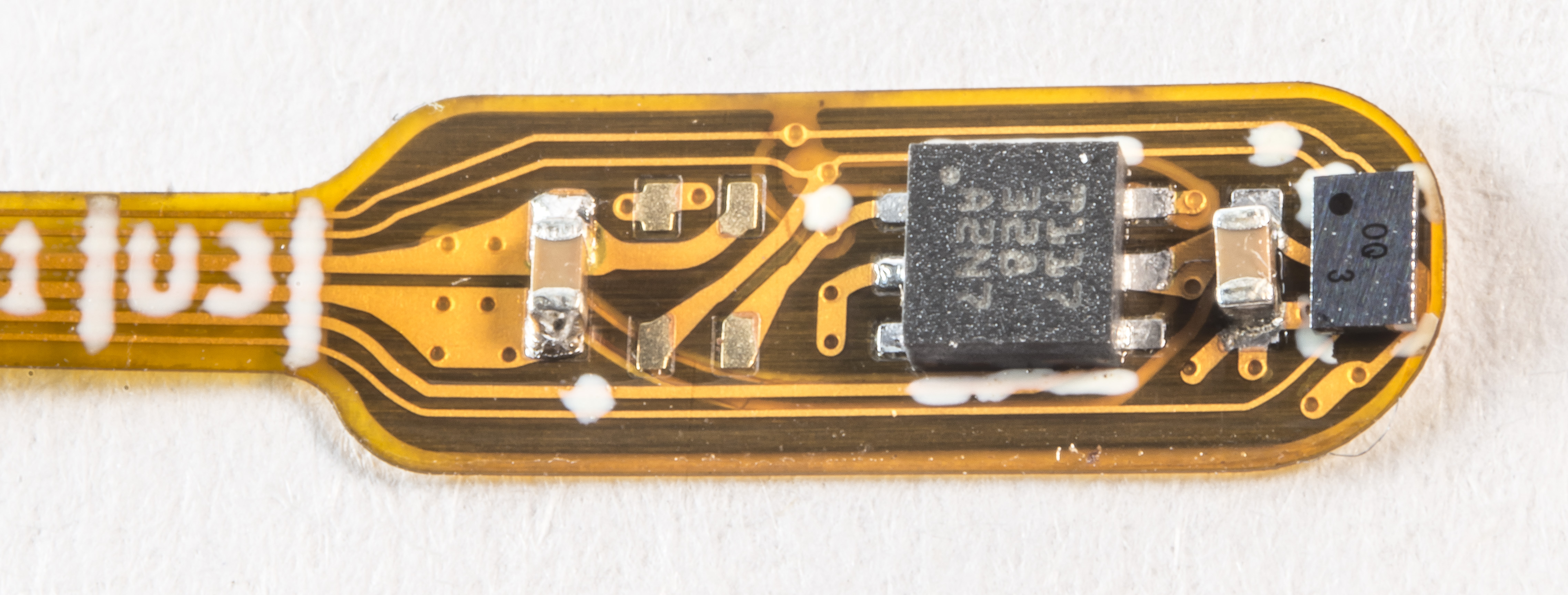
Tiny BGA soldering went smooth and good the first attempt. It is actually pretty easy to see if it soldered well by visual inspection with microscope. Since package has no hidden inside BGA balls it’s easy to verify that all balls reflow into fillet contacts between PCB and chip. Quick check from all four sides reveals good connection and no shorts.
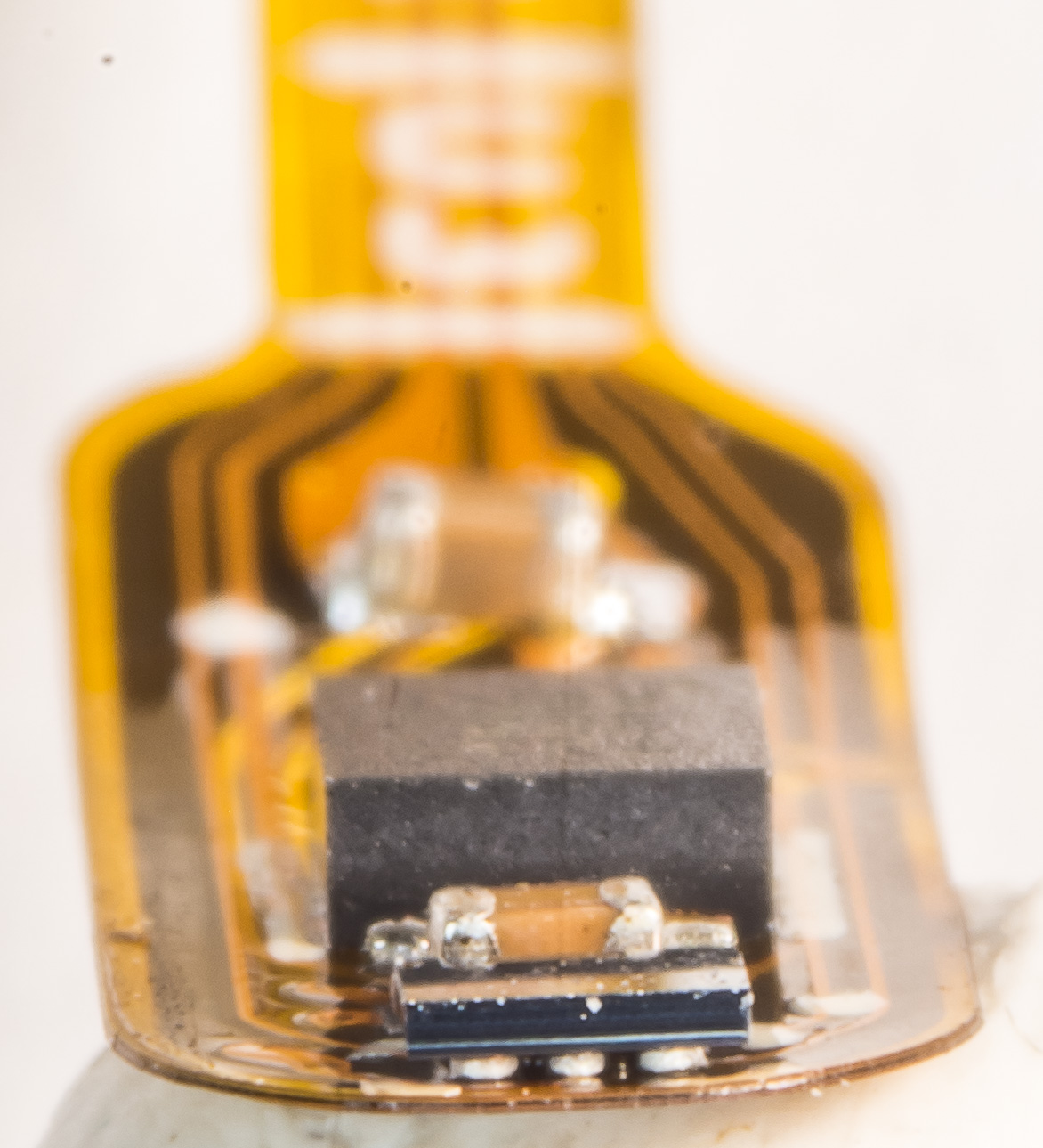
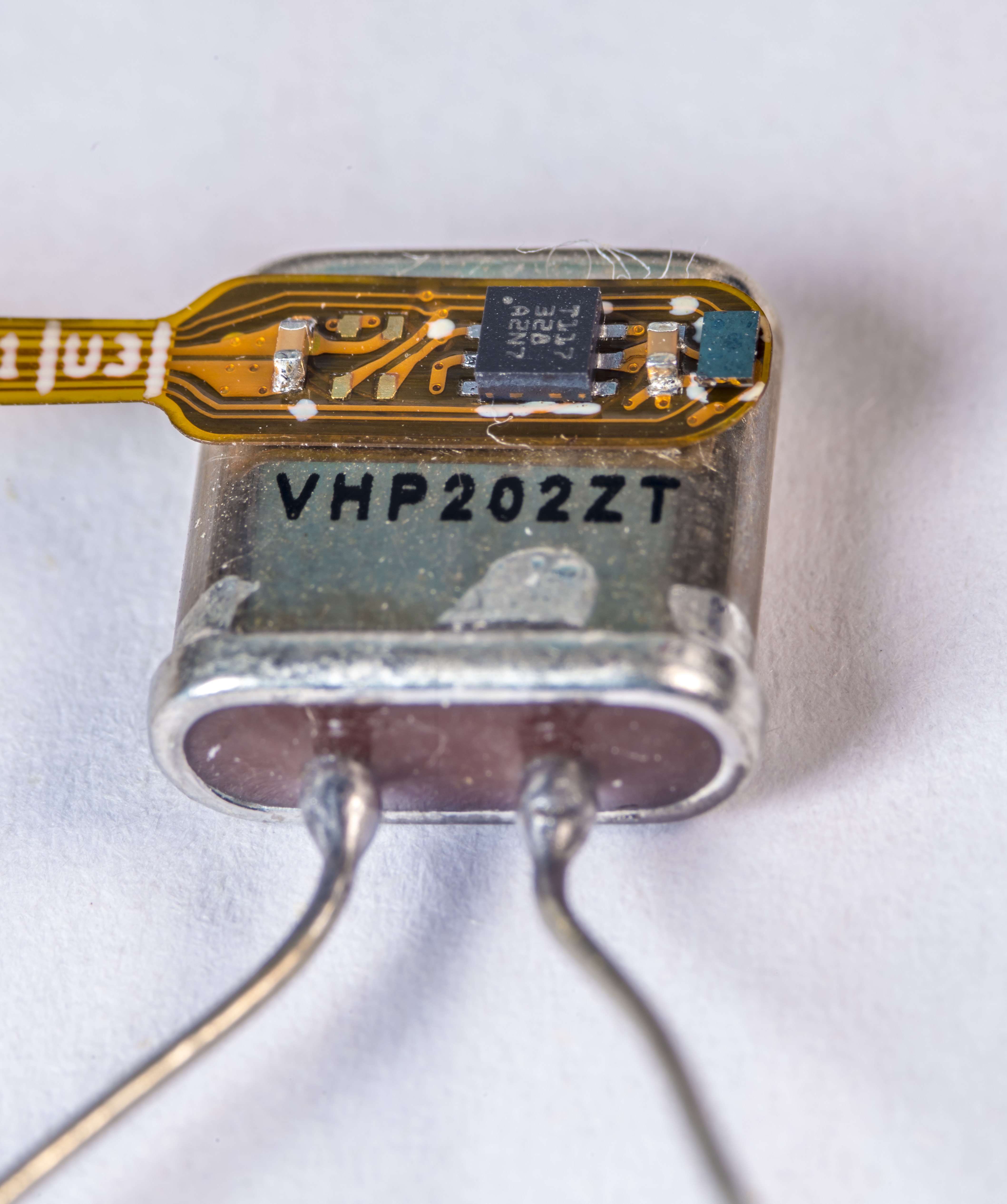
And for the little teaser for one of the future use cases for such compact flexible digital temperature sensor is show on photo below. Flex PCB is thin and compact enough to be attached to a face of VHP202 metal can body.
Big question remains if the digital nature of these sensors would introduce interference and noise into the actual device under test. Digital sensors also dissipate some small but noticeable amount of power. It could be a dealbreaker for very sensitive measurements, such as high resistance (100 MΩ and higher), very low voltages (due to thermal EMF) or very low currents (below nA due to charge injection).
Practical benchmarks will hopefully show the limitations of this sensing approach in future.
Bill of materials and costs
All the bits and parts required to assemble one of these sensor units are presented in BOM table. BOM does not include cable or wiring required to connect sensor to the host device.
| Order | Component and value | Cost per unit | Qty | Ordering link |
|---|---|---|---|---|
| 1 | Temperature sensor, Texas Components TMP117MAIDRV | $1.6 – $3.6 USD | 1 | Digikey, Mouser, TI |
| 2 | Temperature sensor, Texas Components TMP119AIYBGR | $4.2 – $6.8 USD | 1 | Digikey, TI |
| 3 | RH+Temperature sensor, Sensirion SHT45-AD1F-R2 | $6.4 USD | 1 | Digikey, Mouser |
| 4 | Decoupling power capacitor, 0402, 100 nF, X7R MLCC | $0.08 USD | 3 | Digikey |
| 5 | Option 0 Ω resistor, 0402 | $0.02 USD | 2 | Digikey |
| 6 | Qwiic interface connector, JST, 4-position, 1 mm pitch | $0.6 USD | 1 | Digikey |
| 7 | xDevs.com XTH Rev0.0 sensor FlexPCB | $2.8 USD | 1 | PCBWay |
According to this BOM table, total cost of one sensor leaf in minimal configuration (with just one TMP11X sensor, no connector) is $4.6 USD. Populating both TMP sensors and relative humidity sensor brings cost up to $15.9 USD – $20.4 USD. I’d think paying $20 USD for multichannel temperature sensor with accuracy within ±0.1 K is an excellent price/performance feature. Such a sensor can be permanently attached to the device or integrated into the unit and left there for future use, since it’s affordable enough not to worry about the extra cost.
For example typical 1000 Ω platinum RTD Honeywell HEL-705 that I commonly use in lab for temperature measurements is about $117 USD and has datasheet accuracy only about ±0.3 K. Omega 44031 thermistor with nominal resistance 10000 Ω cost about $36 USD. Keep in mind that all of these resistive sensors require separate digitizer such as bench-top digital multimeter or dedicated instrumentation such as Fluke 1529 temperature readout .
Interfacing the sensor board
For sensor tests I’ll use the very popular and common DIY embedded computer platform – Raspberry Pi 4B. Sensor leaf require just four signals to be connected from RPi4 host. These are +3.3V power supply, I2C Clock, I2C Data and ground return line. Like explained earlier in this guide, addressing resistors are configured on the sensor itself and no other external components are required. Connection map is also presented in the diagram, created by WireViz .

Python code library and example applications
First comparison plot with 30 minutes of data between three sensors. TMP117 and TMP119 are populated on the same xDevs.com flex board, while TMP116 is few years old TMP116EVM board. All three of sensors have same 16-bit ADC and fixed 7.8 mK resolution for the readings.
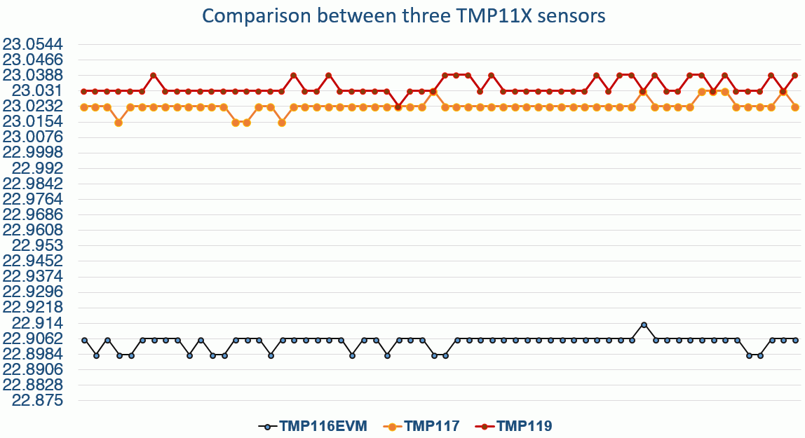
Longer comparison also show good agreement between different sensors in the same location with air-bath:
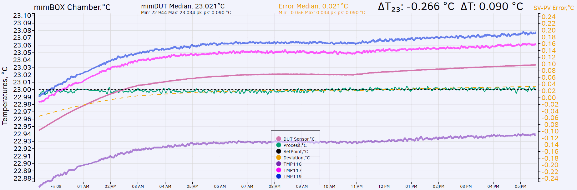
All sensors are placed in the thermal well of ESI SR104 resistance standard during calibration process in air-bath with fixed +23.0 °C. Agreement between TMP117 and TMP119 is pretty remarkable.
Integration with xDevs.com TECkit
Conclusion and project summary
I’m pretty happy with this project outcome and further tested the caveats and prototype manufacturing of small flexible PCB design for temperature sensing application. In total this project took about 3-4 hours from the idea to the finished Gerber files plus another hour to order the necessary components and assemble the first running prototype.
Many engineers afraid to try flexible PCB designs, but they are actually not as scary to do as 10 years ago. Hopefully this example showcase the simplicity and flexibility that these designs can offer, and we would see much more ideas and interesting variants of FPCBs in metrology projects and products in future.
Also real-time discussion about this article and related stuff is very welcome at our own xDevs.com IRC-chat server: xdevs.com (standard port 6010, channel: #xDevs.com). Web-interface for access mirrored on this page.
Projects like this are born from passion and a desire to share how things work. Education is the foundation of a healthy society - especially important in today's volatile world. xDevs began as a personal project notepad in Kherson, Ukraine back in 2008 and has grown with support of passionate readers just like you. There are no (and never will be) any ads, sponsors or shareholders behind xDevs.com, just a commitment to inspire and help learning. If you are in a position to help others like us, please consider supporting xDevs.com’s home-country Ukraine in its defense of freedom to speak, freedom to live in peace and freedom to choose their way. You can use official site to support Ukraine – United24 or Help99. Every cent counts.
Modified: Feb. 4, 2026, 1:07 a.m.