This DMM was acquired by our visiting member LC for his own homelab capability improvements. It was sold on secondary market as broken , but demonstrated to power up. Early serial number of this instrument suggested manufacturing date around 1990-1994. Very common issue with these older instruments is related to leaking electrolytic capacitors near hot power regulators and subsequent destruction of fragile 4 layer analog PCB. xDevs has lot of experience repairing more than 10 different Model 2001 and some Model 2002 with this issue. So this was expected to happen here too.
After all electrolytic capacitor replacement analog PCB was carefully cleaned and inspected. No significant damage around caps was observed so next step was to power up, measure power rails for health and see what self-test process would return.
Meter threw nearly all possible errors, starting with codes for ADC.
Instrument error report after recapping:
| Error | Display message | Fault message |
|---|---|---|
| 200.1 | A/D operation | No ADC communication |
| 200.2 | A/D operation | ADC signal conditioning noisy |
| 201.2 | Testcal | Cannot measure 7V at A/D |
| 201.3 | Testcal | Cannot measure 1.75V at A/D |
| 202.2 | Integration | Integration period bit I15 |
| 202.4 | Integration | Integration period bit I14 |
| 202.6 | Integration | Integration period bit I13 |
| 202.8 | Integration | Integration period bit I12 |
| 202.10 | Integration | Integration period bit I11 |
| 202.12 | Integration | Integration period bit I10 |
| 202.14 | Integration | Integration period bit I9 |
| 202.16 | Integration | Integration period bit I8 |
| 202.18 | Integration | Integration period bit I7 |
| 202.20 | Integration | Integration period bit I6 |
| 202.22 | Integration | Integration period bit I5 |
| 202.24 | Integration | Integration period bit I4 |
| 202.26 | Integration | Integration period bit I3 |
| 202.28 | Integration | Integration period bit I2 |
| 202.30 | Integration | Integration period bit I1 |
| 202.32 | Integration | Integration period bit I0 |
| 300.2 | A/D MUX | A/D MUX 1.75V reference, X5 A/D MUX gain |
| 300.3 | A/D MUX | A/D MUX 0V reference, X50 A/D MUX gain |
| 302.1 | ADGND | MUX Signal zero to ADGND |
| 302.3 | ADGND | MUX Ohms LO to ADGND |
| 302.4 | ADGND | MUX Divider LO to ADGND |
| 303.1 | Input buffer | Input buffer |
| 305.1 | 20V range MUX | 20V range multiplexer REFHI |
| 305.2 | 20V range MUX | 20V range multiplexer REFLO |
| 305.3 | 20V range MUX | 20V range multiplexer zero |
| 306.1 | Ohms | 9.6μA ohms source |
| 306.2 | Ohms | 1.92μA ohms source |
| 401.1 | Regulator | Regulator |
| 402.1 | Freq. Switch | Frequency switch |
| 406.6 | Sample/hold | Sample and hold circuit |
| 500.1 | Amps/LO ohms | 96μA ohms/200μA DCA range |
| 500.2 | Amps/LO ohms | 960μA ohms/2mA DCA range |
| 500.6 | Amps/LO ohms | 200mA DCA range |
| 500.7 | Amps/LO ohms | 2A DCA range |
| 501.1 | Amps protect | Amps protection |
| 501.2 | Amps protect | Amps bootstrap |
| 502.1 | ACA switch | AC amps switch |
| 600.1 | Ohms sense | Ohms sense HI |
| 600.2 | Ohms sense | Ohms sense LO |
Because xDevs had multiple K2002 during meetup to be used as comparison further testing revealed that digital board is OK, but ADC module and analog boards have faults.
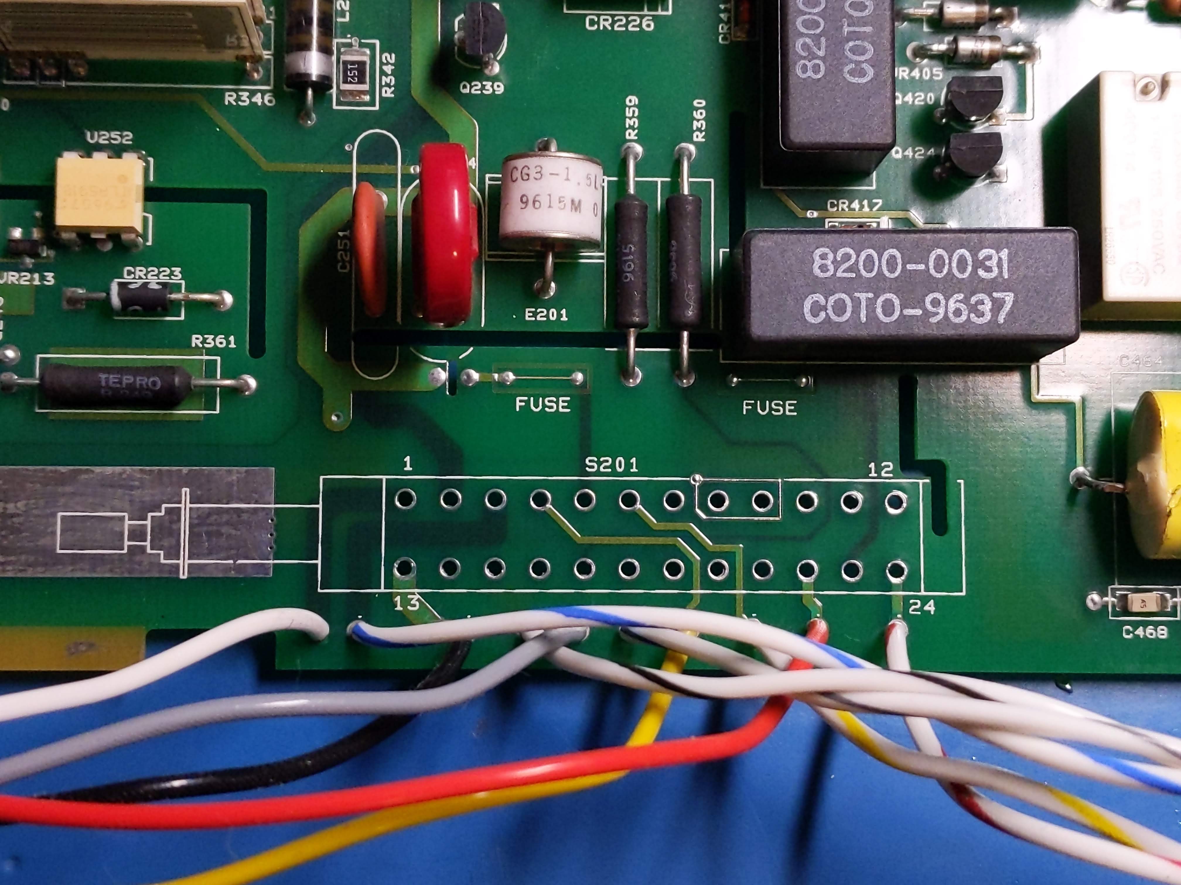
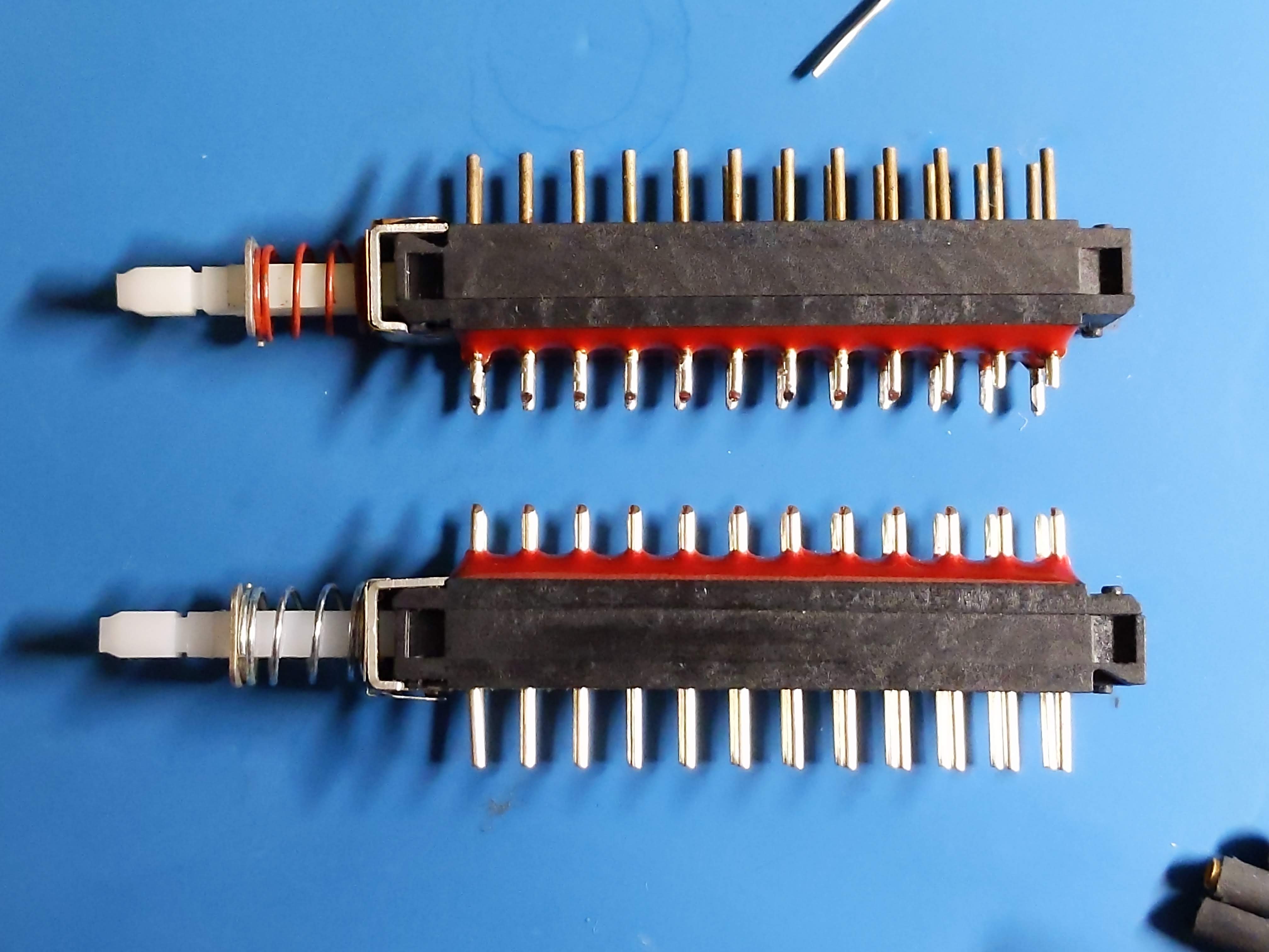
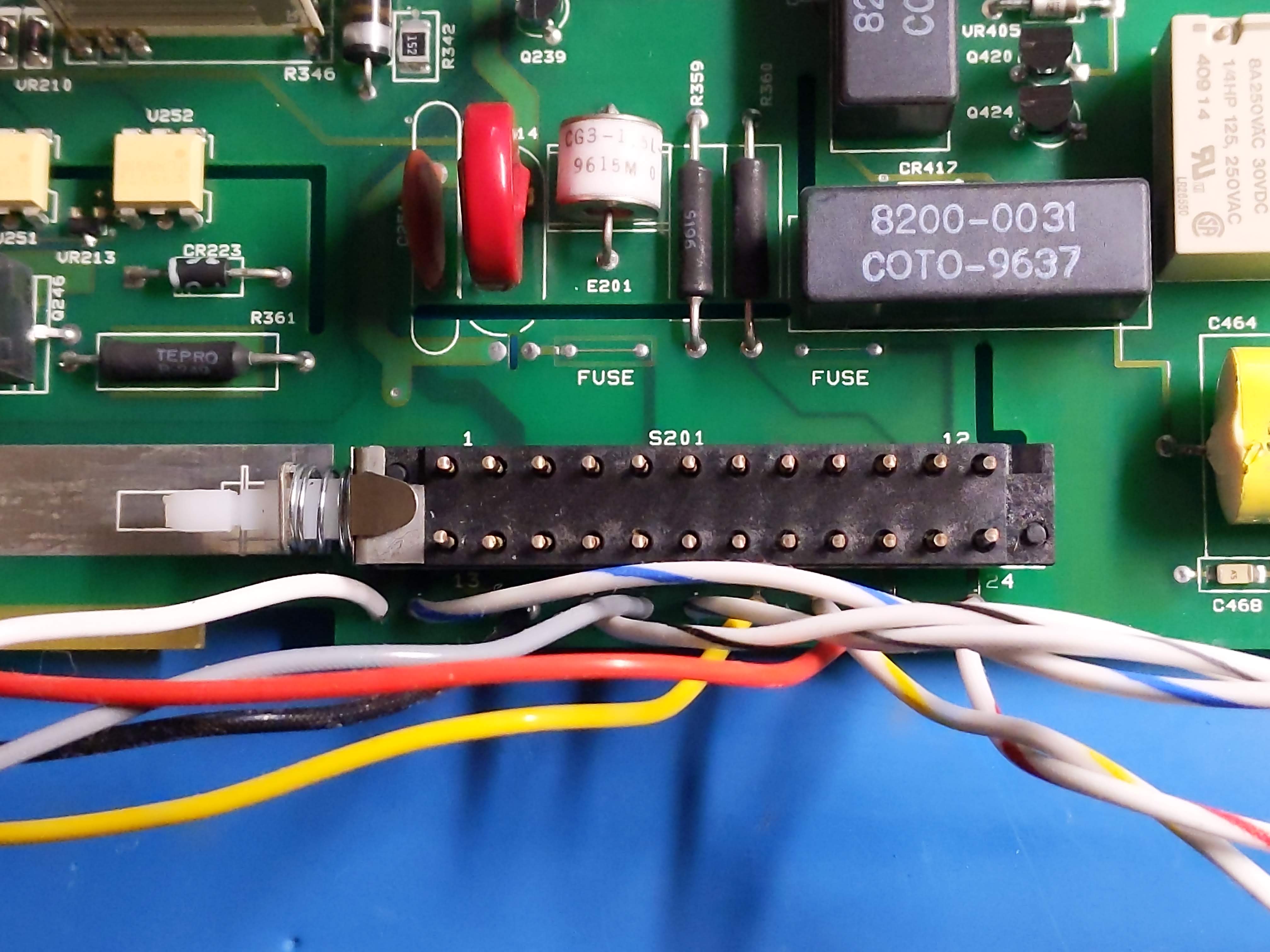
Replacement of the original axial fan with an Delta AFB0412SHB-SP04 (12 DCV, 40 mm², 0.414 m³/min) was done. Front/Rear Switch replaced with a brand new equivalent.
ADC appears to be noisy which is causing most of the errors. It was confirmed bad in another good K2002 unit as well. Reflowing R827 reduced amount of errors from the ADC module to 200.1, 200.2 and 202.4 in good working K2002 unit. This setup reduced the noise level by at least 100 times. Later suspect resistor network was replaced with a NOMCT16035001AT1 (isolated, 5k x 8, 0.1 %, 25 ppm/K). Tantalum capacitors (C834, C835) were upgraded to higher voltage ratings (> 25 V). Other components replaced include: U812 (SD5400C), U806 (74HC02), U807 (74HC02) and U820 (74HCT175) but it didn’t improve faults.
However the replacement of Q801 to Q804 (both VN0605T MOSFETs) cleared most errors attributed to ADC noise.
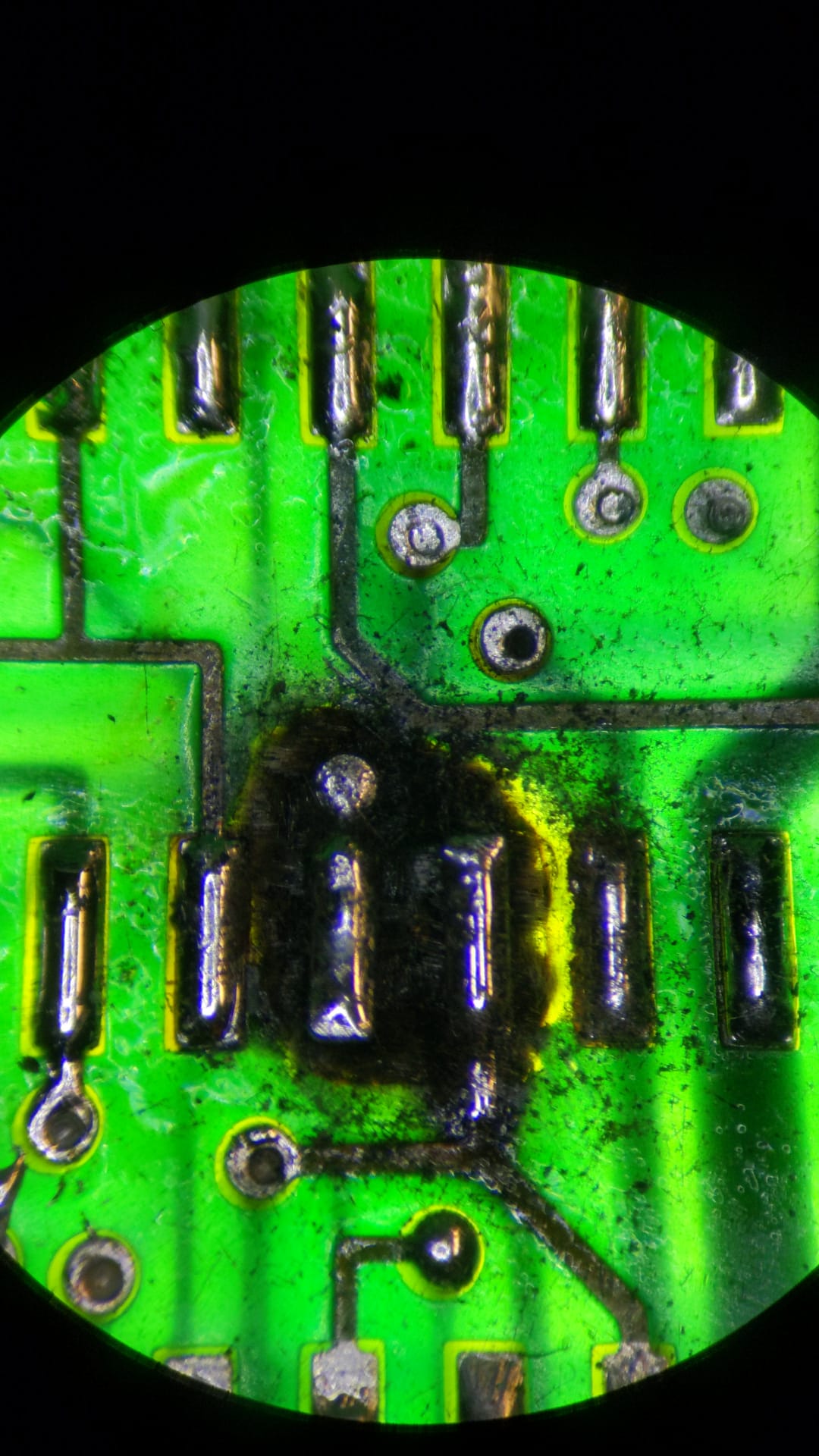
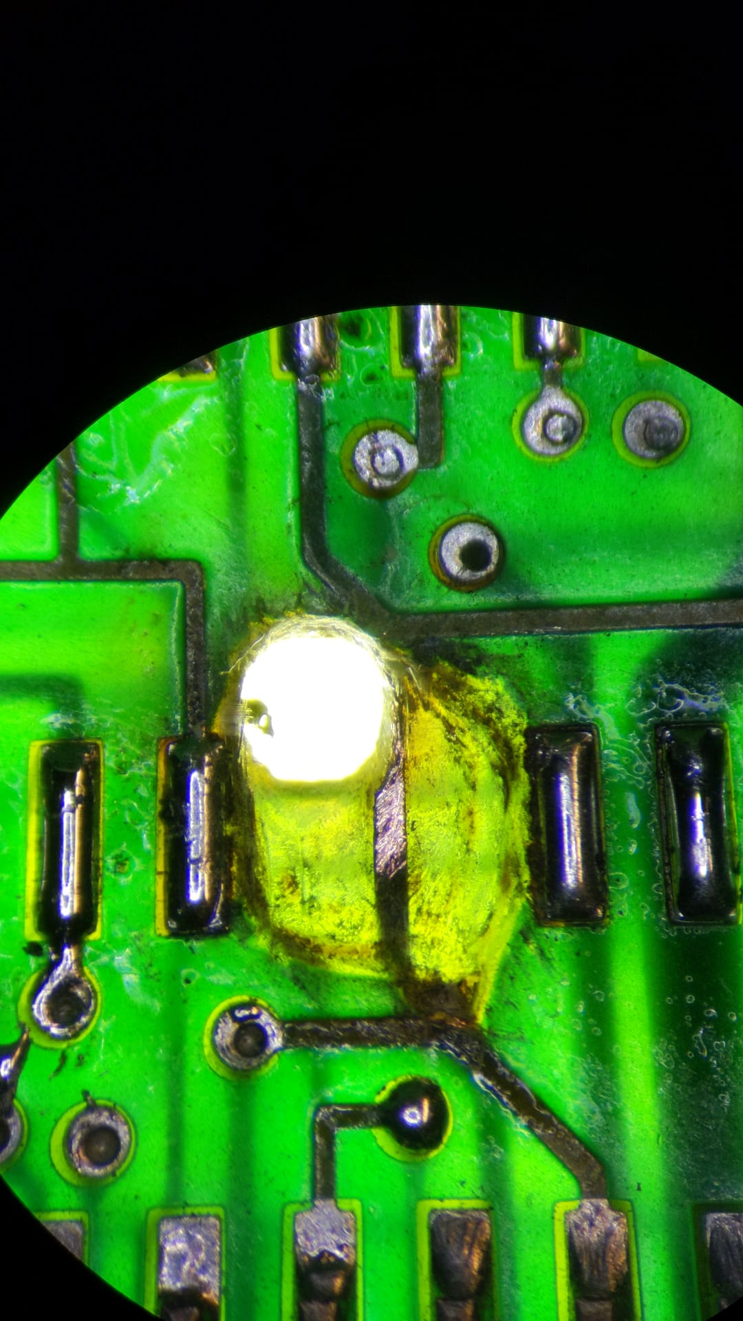
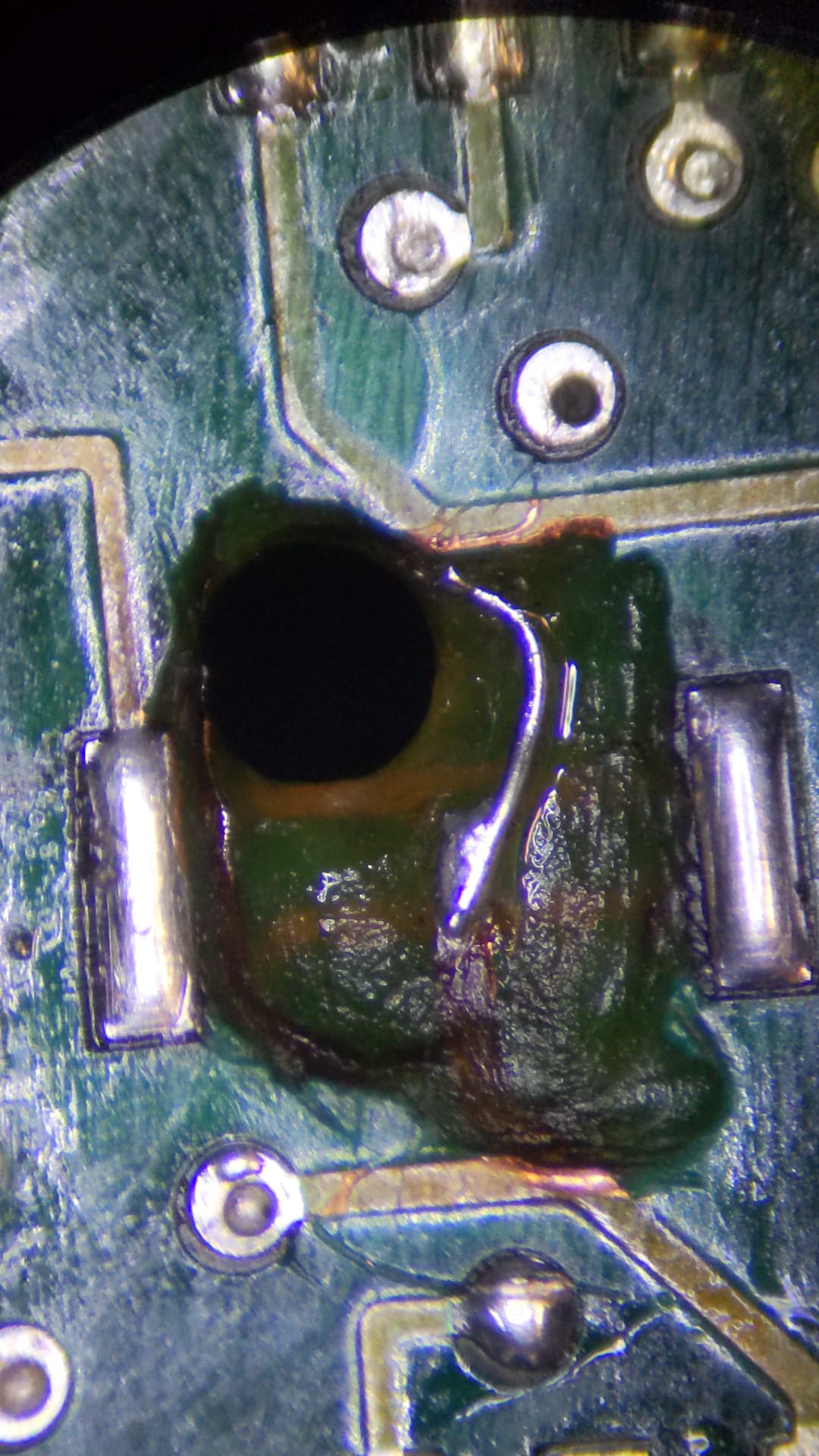
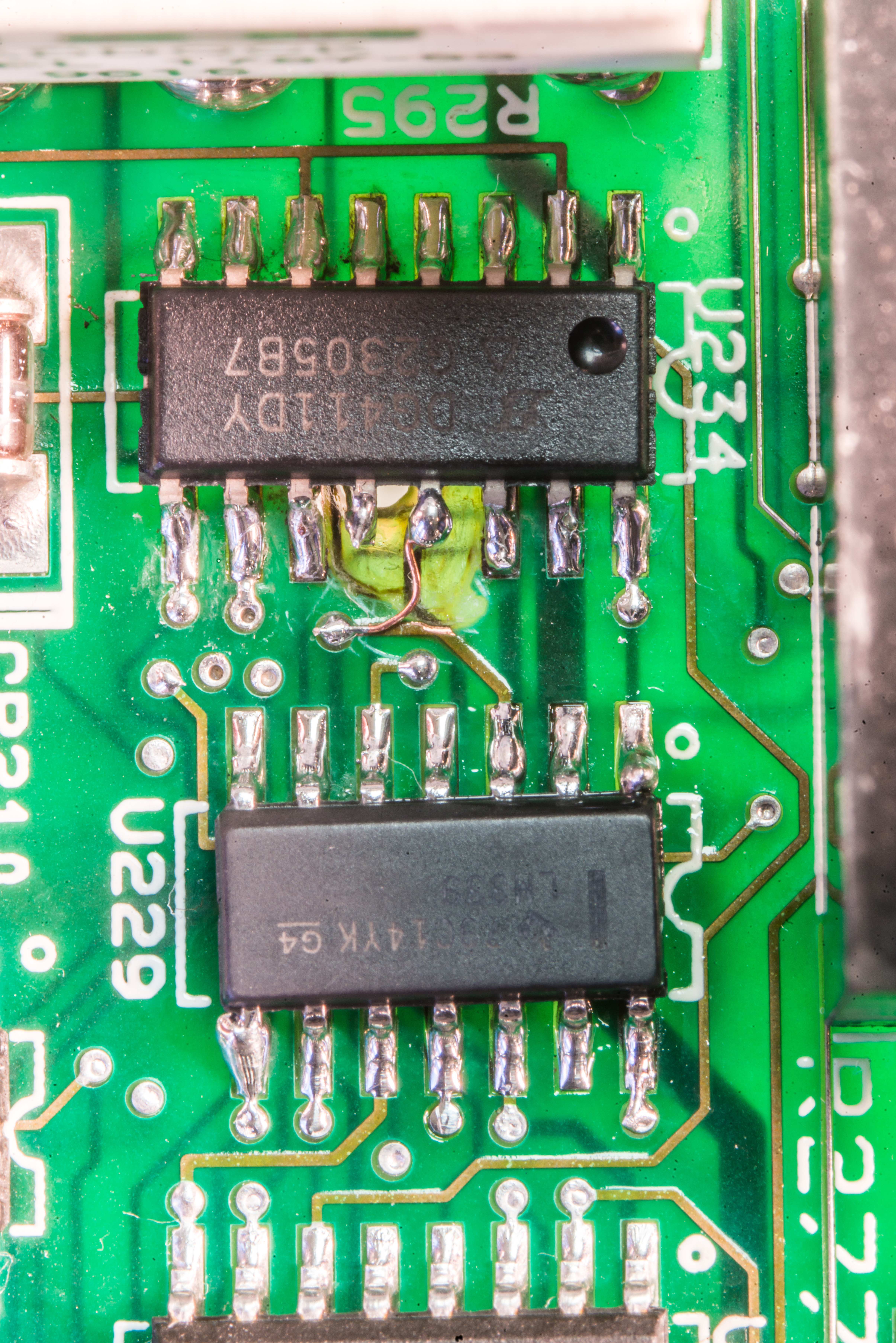
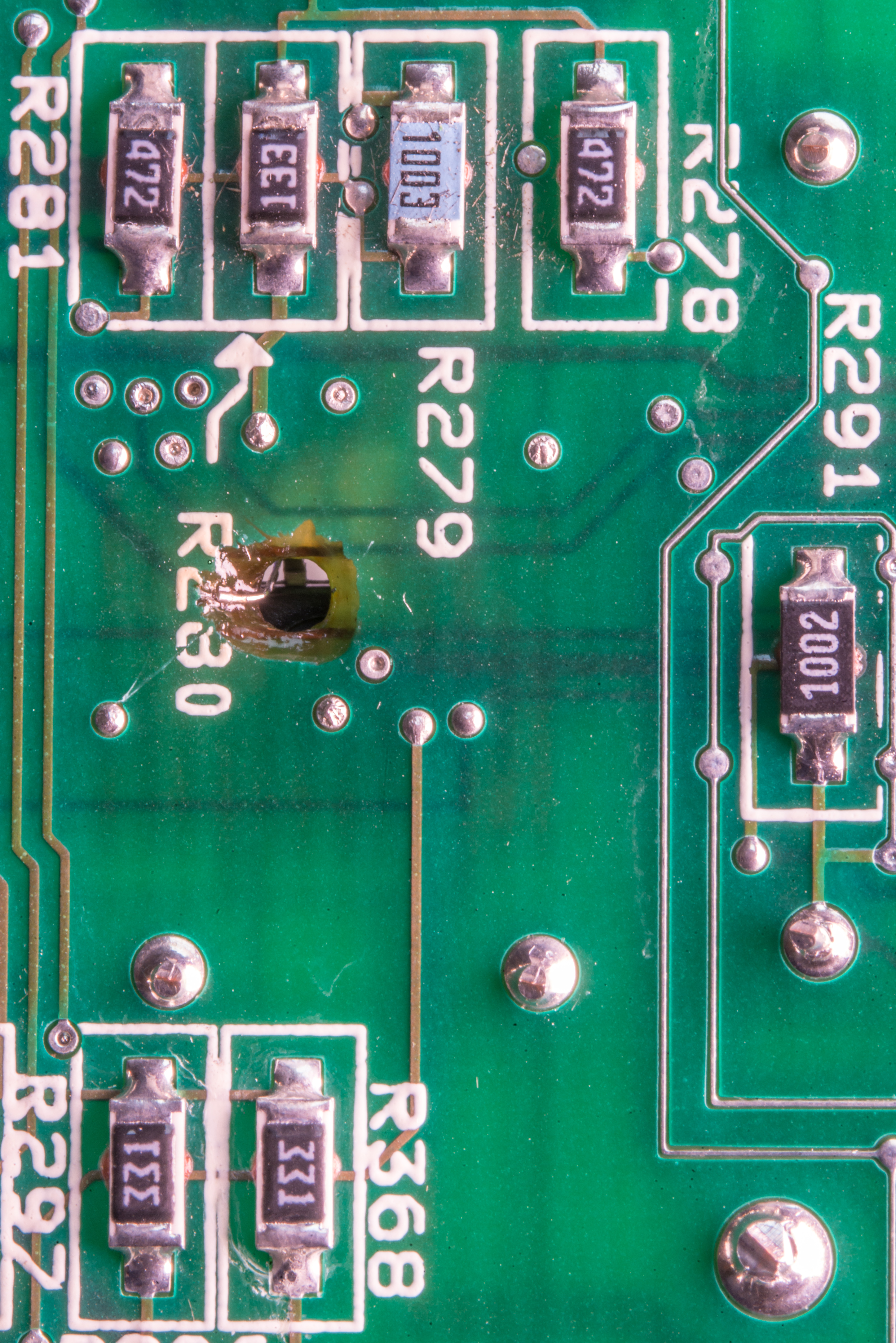
The faulty Analog board has the following issues when a working ADC is used now: 500.1, 500.2, 500.3, 500.4, 500.6, 500.7, 501.1, 501.2, 502.1. This is because Keithley 2002 also had faults and damage on analog board. U234 DG411 switch near the current sense resistor network R295 went into meltdown mode and burned the hole in PCB. Errors are most likely attributed to the damaged region near the U234 package (DG411DY).
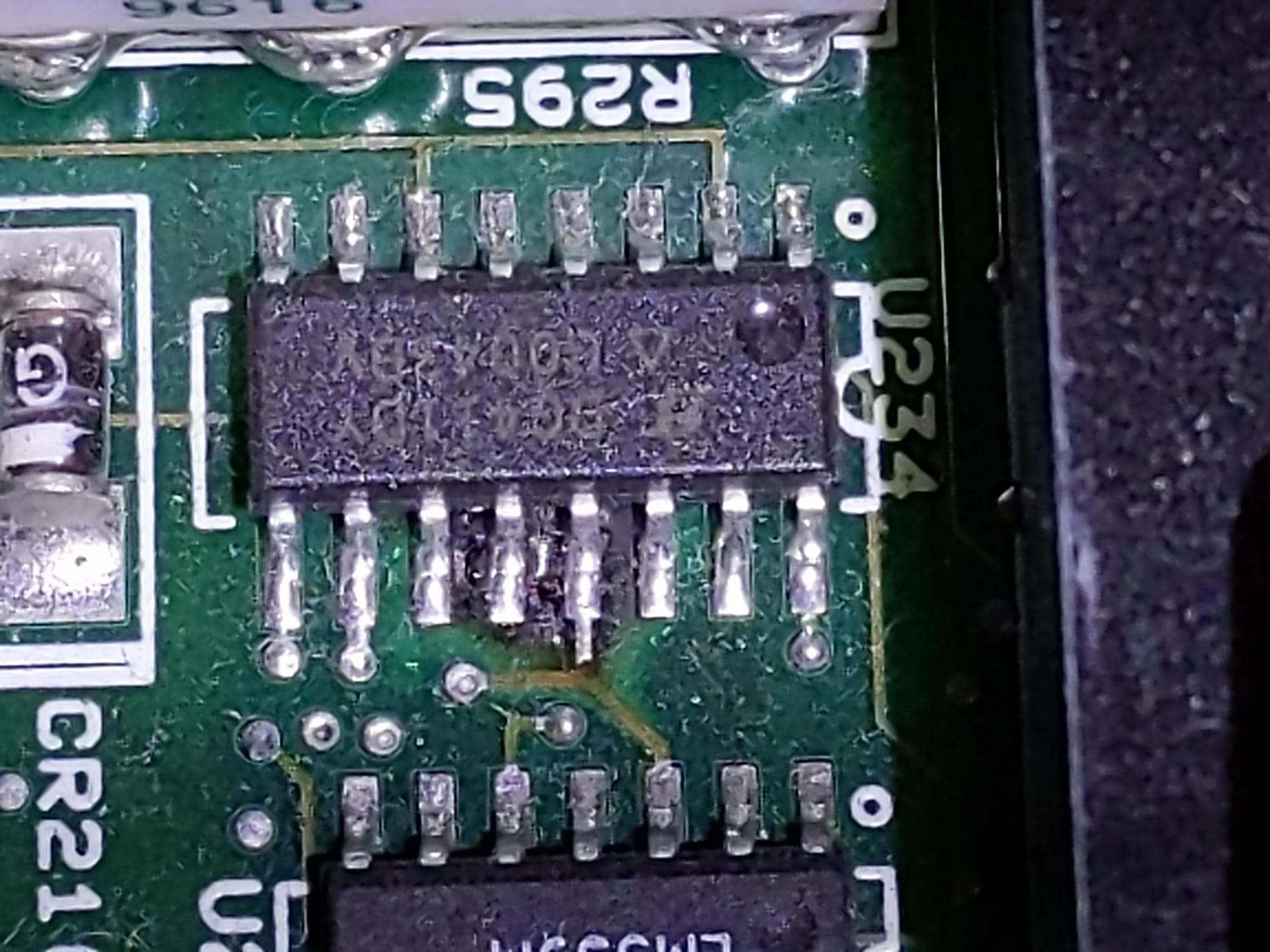
Only way to repair such problems is to remove ALL carbonized PCB fiber/epoxy material with scalpel/dremel, restore all electrical connections on multilayer PCB.
Pads under blown PCB are removed as well to get access into board. Keithley analog board is 4 layer and does not have ground planes inside, which makes this job easy one. But steady hands and microscope are still a must.
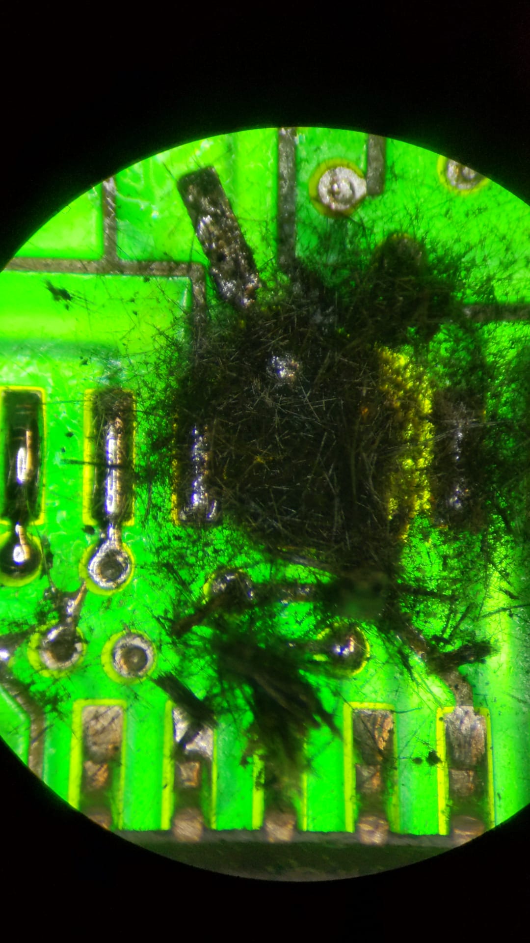
All damaged dielectric is removed all the way thru the board, with remnant of the via hanging for it’s life on copper trace from layer 3.
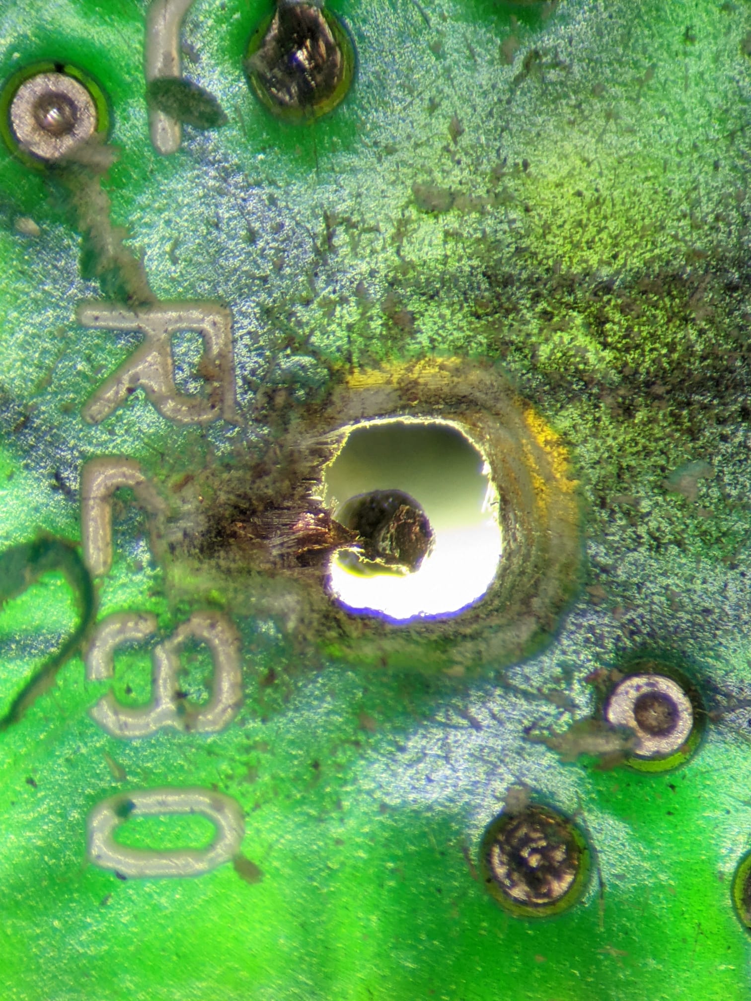
Broken trace on layer 2 also need connectivity repair. For that I use single copper strand out of multistrand AWG28 cable.
And jump-wire in the cavity installed.
Common components affiliated with the 500 series errors: U233 (OP97FSZ), U220 & U234 (DG411DY), U222 (DG408DY+), U223 & 232 (MAX326CSE+), U225 (LT1097S8), U226 (LT1007ACN8), Q211 (3N163), Q212 (2N3906-G), Q213 (2SK1413), MISC: CR217, K201, R322, R334, and R342. The set of 500 series errors is related to the U229 comparator (LM339D) on the Analog board and after replacement all errors have been cleared after the U229 (LM339D) was replaced.
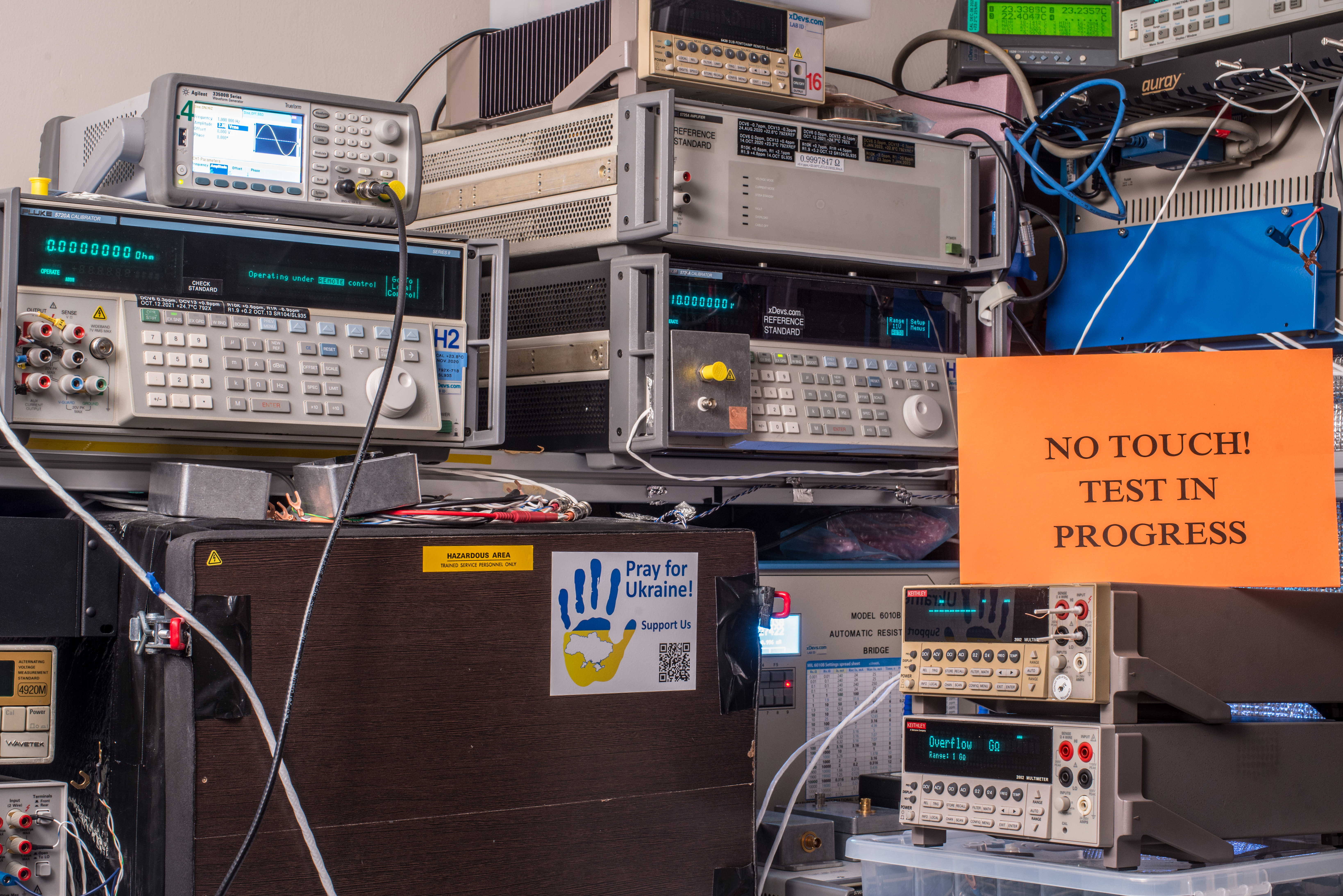
Keithley 2002 is repaired, fresh adjusted and calibrated. Calibration report attached. Hulk2 used as reference and verification source, except ACV function. ACV function tested with boosted Hulk1 setup (5720A + 5725A) due to volt/frequency limits.
There is minor deviation on negative polarity of 2V range, but it is likely to be systematic error due to issues with Hulks. This can be corrected in next CF2024. 2A current range points are valid only after 30 minute warm-up of shunts in K2002.
Projects like this are born from passion and a desire to share how things work. Education is the foundation of a healthy society - especially important in today's volatile world. xDevs began as a personal project notepad in Kherson, Ukraine back in 2008 and has grown with support of passionate readers just like you. There are no (and never will be) any ads, sponsors or shareholders behind xDevs.com, just a commitment to inspire and help learning. If you are in a position to help others like us, please consider supporting xDevs.com’s home-country Ukraine in its defense of freedom to speak, freedom to live in peace and freedom to choose their way. You can use official site to support Ukraine – United24 or Help99. Every cent counts.
Modified: Aug. 24, 2023, 2:58 a.m.