Since 3458A’s release by HP in 1987 we did not get much of the improvement for high-resolution DC voltage measurements in the commercial benchtop instruments. This is due to number of reasons and challenges, both in hardware design and metrology related to it. We are still years away from getting close to practical 9 digit DC voltmeter without the help of cryogenics and commercial viability.
Until then we can experiment and play with small improvement ideas. Such as making lower noise zener references for the existing 3458. If one just take original HP A9 PCBA, replace LTZ1000A with Analog Devices ADR1000, replace resistors to match the new ADR1000 requirements and reinstall the modified module, we could get a bit lower noise. However to make the meter fully functional again with much lower voltage output from the zener reference chip we need to reduce min limits for acceptable reference voltage from 7.1V down below 6.6V in firmware. Without this step meter will not be able to complete ACAL and unable to self-adjust all the ranges and functions. Another way is to increase the voltage provided to the meter in hardware.
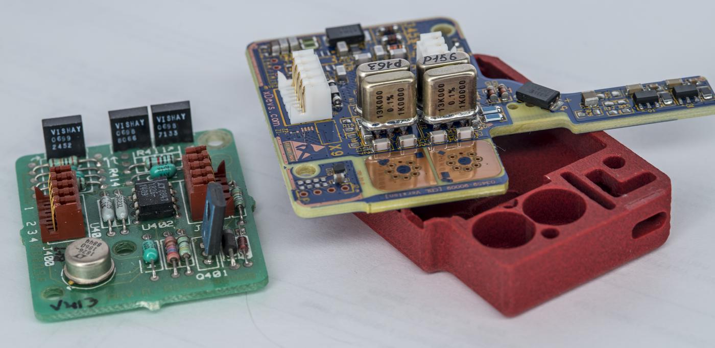
Original HP-designed A9 PCB module is also not the best choice to push for lower noise zener implementation, so I’ve decided instead to build own custom zener core module as a plug in replacement. This way we can easily swap different reference modules and maintain capability to revert the instrument to original LTZ1000A A9 at any time in future. This is especially handy for newer ADR1000 chips which exhibit a lot of initial drift in first few years , compared to the older yet still undefeated LTZ1000A product (in terms of long-term stability).
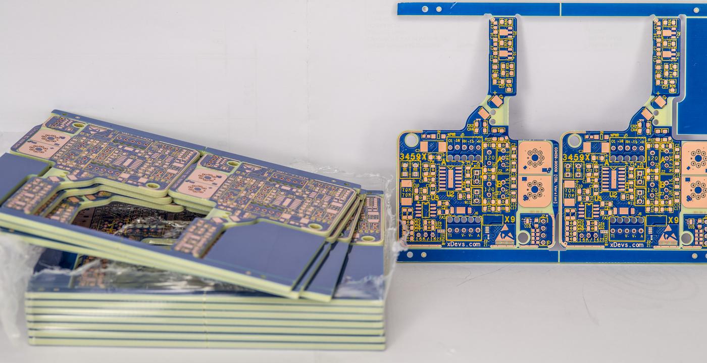
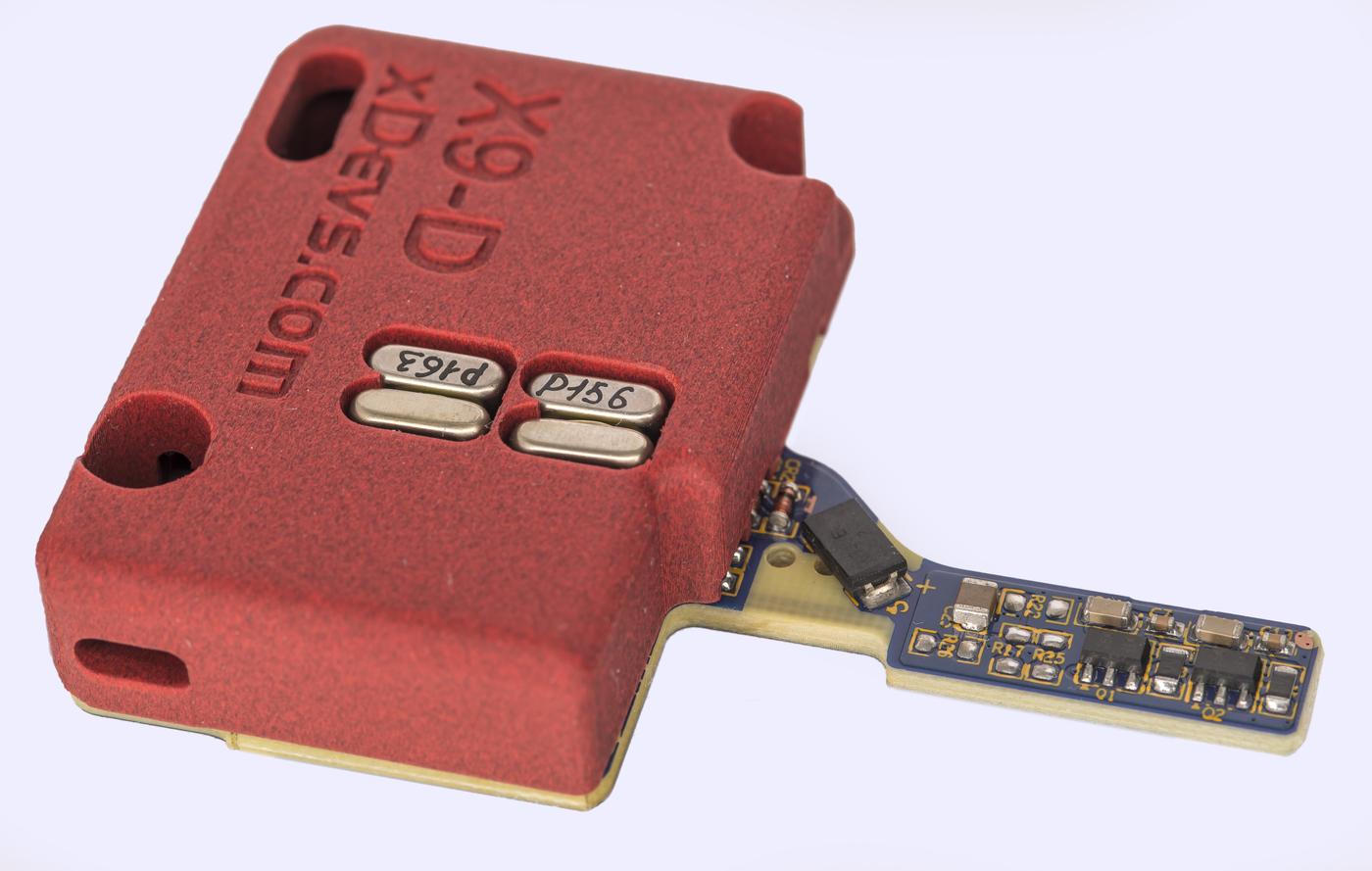
And to push zener noise even further new custom X9-D module implements not just one but two independent ADR1000-based cores on the same 4-layer substrate. Outputs are averaged and combined with passive RC network and optionally amplified to little higher 7.1V level to make this module compatible with standard Rev 9 HP3458A firmware.
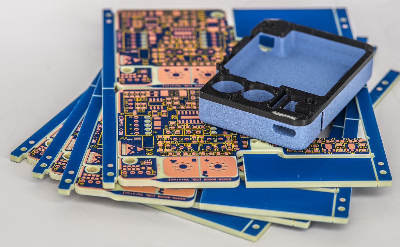
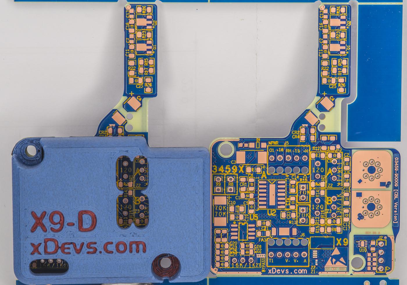
To protect the sensitive reference module from airflow draft and further reduce heat loss module is fully enclosed with 3D-printed plastic cover from both top and bottom sides. Total power consumption of the 6.622V output voltage, with typical dual ADR1000 is about 1 W – 1.3W. PLA-CF material was used with FDM printer to make covers.
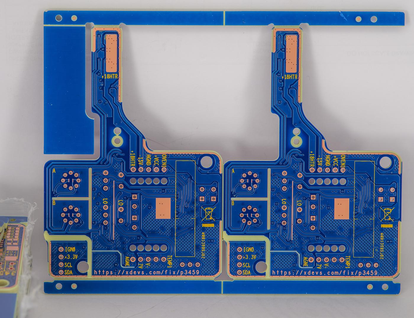
There is also additional fully isolated digital temperature sensor onboard, based on Texas Instruments TMP117 chip in DFN6 package. Hot parts such as power transistors for heater drives and ground current compensation resistors are placed far away from sensitive reference circuits on the non-covered “finger”.
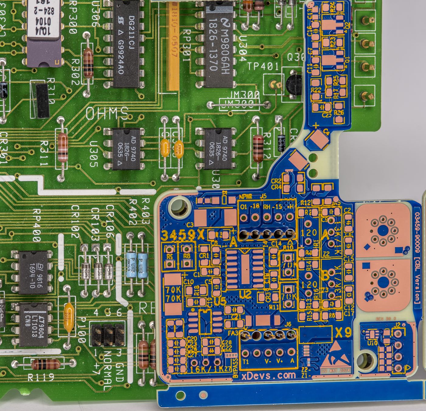
This finger extended across non-critical A1 components closer to the cooling fan, which should help a little with heat dissipation. PCB in X9-D module utilize four copper layers with heavy copper utilization to reduce hotspot gradients across the board. Board is also using thicker dielectric with total stackup height 2.0 mm to further separate sensitive signals from the power and high-current nodes internally. There are no voodoo slots or cutouts, since the module is quite small and does not have rigid mount to the instrument enclosure. In essence this X9-D design is evolution of our internal quad-zener 6-layer module QVR but at half of the price, half the power and quarter of the physical footprint area.
All the components are mounted only on the top side, this way single side stencil can be used for SMT assembly. Key important resistors are BMF type such as Vishay Precision Group VHP202 and VHD200 to ensure low tempco and good long-term stability of zener temperature setpoint and current. Board plugs into 3458A’s A1 board the same way as original. X9-D is a bit wider but there is still room left to clear the area for the cables from instrument’s rear terminal posts. Finger on X9-D module just clears test probe points on A1 and Q30 TO-92 transistor. There are just few digital control components in the area on A1 board, so added heat should not be much of a problem here. But this will be tested later on as well to confirm good resistance function operation.
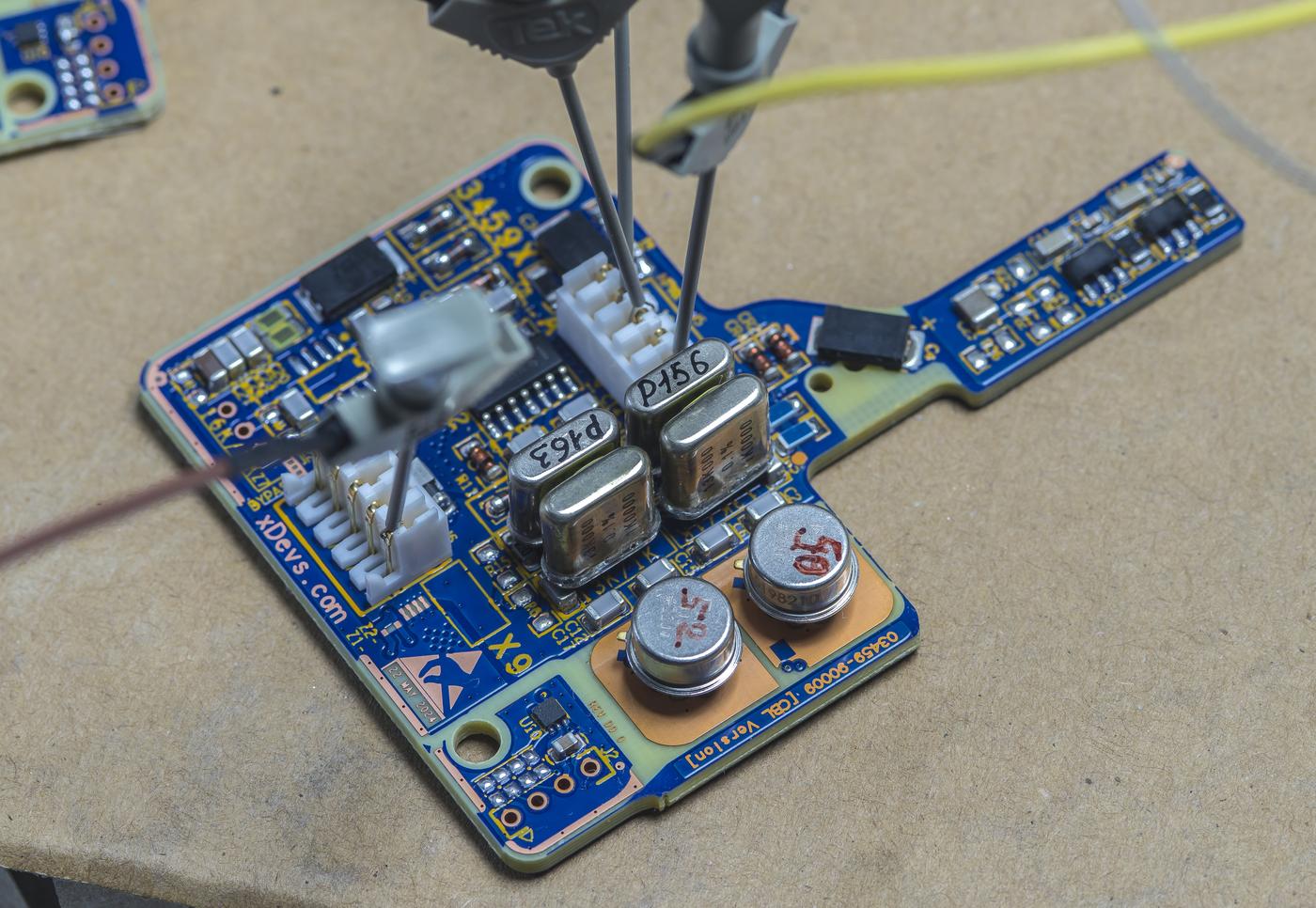
First module was assembled 14 June 2024. It featured two ADR1000 chips and does not have optional boost stage. Initial output voltage was measured at +6.6227 VDC ±2 µV/V. ADR chips were not aged or treated prior to assembly. For first prototype I’ve chosen 13 kΩ | 1 kΩ resistor network in as well as 80 Ω current setting resistor. Both are metal foil type in the hermetic packaging to maintain good temperature and long-term stability. At least we wouldn’t have to worry about these resistors in design.
Initial 6.622V output noise measurement with standalone X9-D module and paired ADR1000 using 0.1 Hz – 10 Hz 80 dB LNA revealed very promising performance. X9-D was powered from the Fluke 792A power battery pack to ensure quiet power and avoid any chance of the ground loops that might affect sensitive measurement.
With 80 Ω zener current resistor noise level at ~347 nV peak to peak is well in line with theoretical expectation which was: ~500 nV noise from single ADR1000 / SQRT 2 = 353 nV peak-peak. Zener current for both chips was set to be around 5.5 mA with this value. Bumping the current a bit more with 44 Ω resistors instead yields even better noise with reduction about 34%.

On the shorter time span noise is around 185 nV peak to peak across 35 captures in 0.1 Hz- 10 Hz bandwidth. This is more than five times quieter than factory original 03458-66509 LTZ1000A-based module and should unlock the possibility to test other modifications to this meter with the aim of improving short-term performance for the DC voltage measurement function.
Stay tuned for more results in future on xDevs pages, once we complete the measurements and tweaks. X9-D module design shown here is not open at this point, it is only a first prototype for testing and sorting out possible bugs and issues. If you are interested and want to discuss details, you are welcome at our own IRC chat server: xdevs.com (port 6010, channel: #xDevs.com) or by reaching out with email.
Projects like this are born from passion and a desire to share how things work. Education is the foundation of a healthy society - especially important in today's volatile world. xDevs began as a personal project notepad in Kherson, Ukraine back in 2008 and has grown with support of passionate readers just like you. There are no (and never will be) any ads, sponsors or shareholders behind xDevs.com, just a commitment to inspire and help learning. If you are in a position to help others like us, please consider supporting xDevs.com’s home-country Ukraine in its defense of freedom to speak, freedom to live in peace and freedom to choose their way. You can use official site to support Ukraine – United24 or Help99. Every cent counts.
Modified: June 25, 2024, 4:30 p.m.

