Intro
ESI (today under IET) used to build and make hammon-style dividers build with high-stability wirewound resistors for accurate fixed ratio transfers with sub-ppm uncertainty. These devices are sold under model names SR1010, SR1030, SR1050 and as a set in SR1060 system.
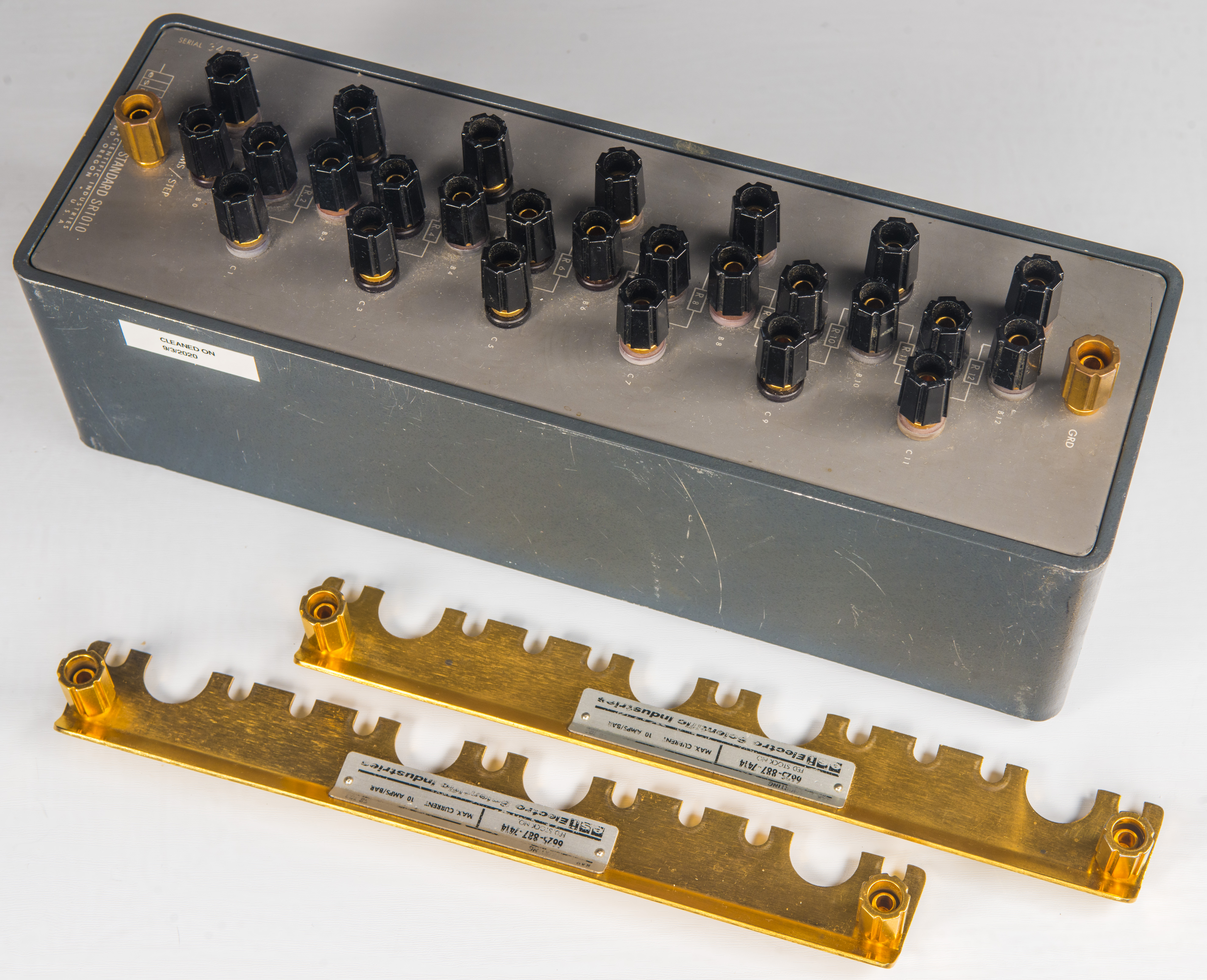
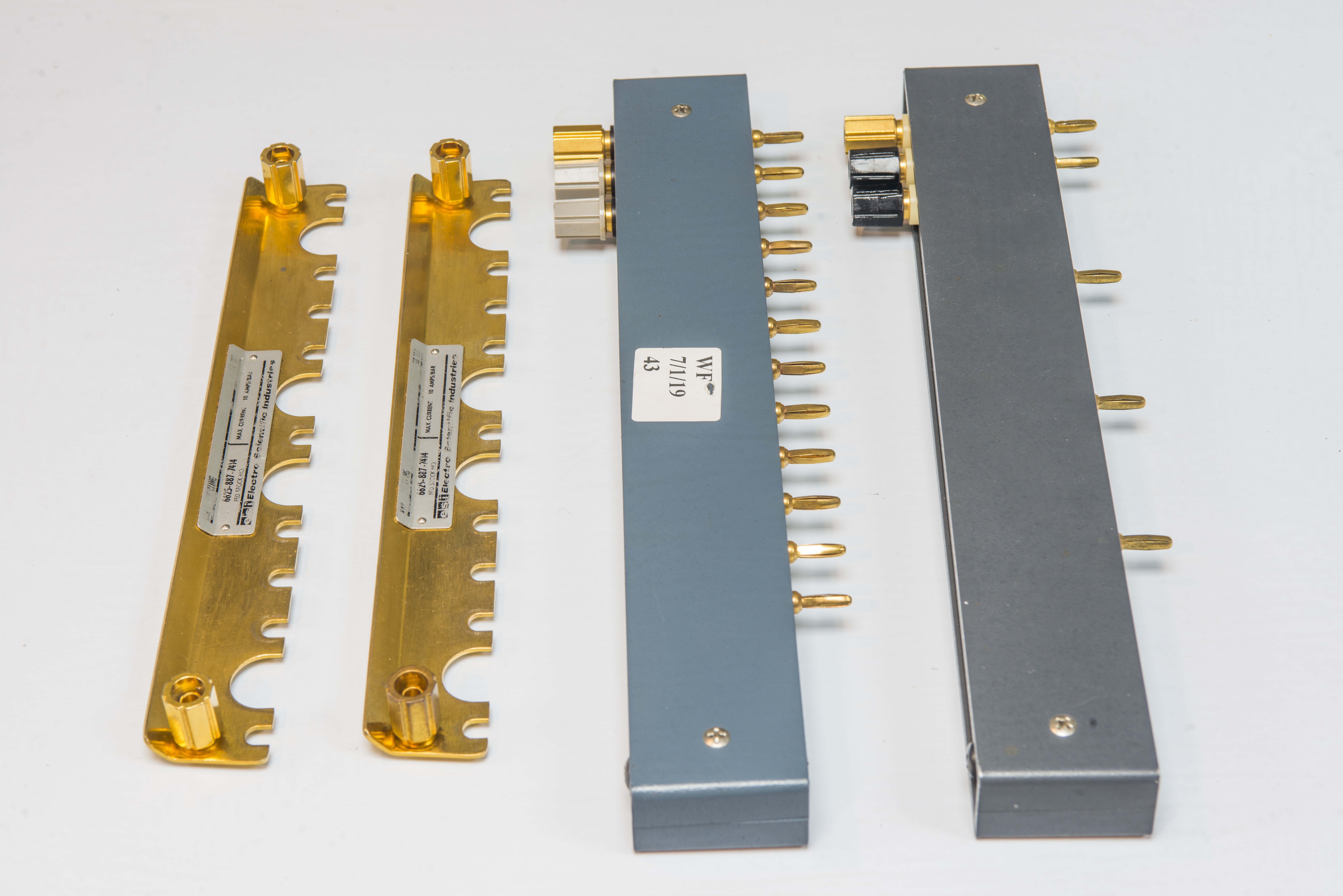
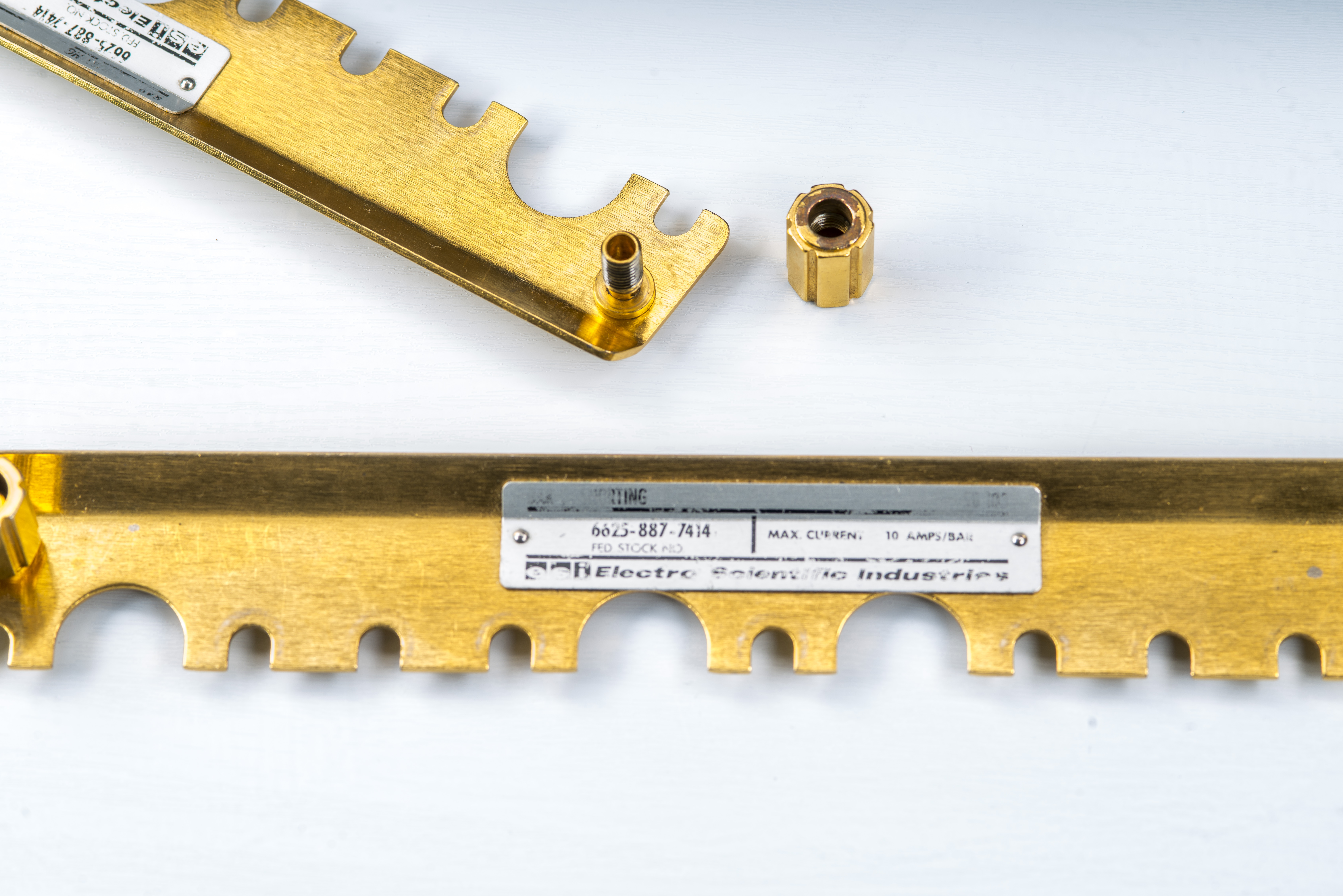
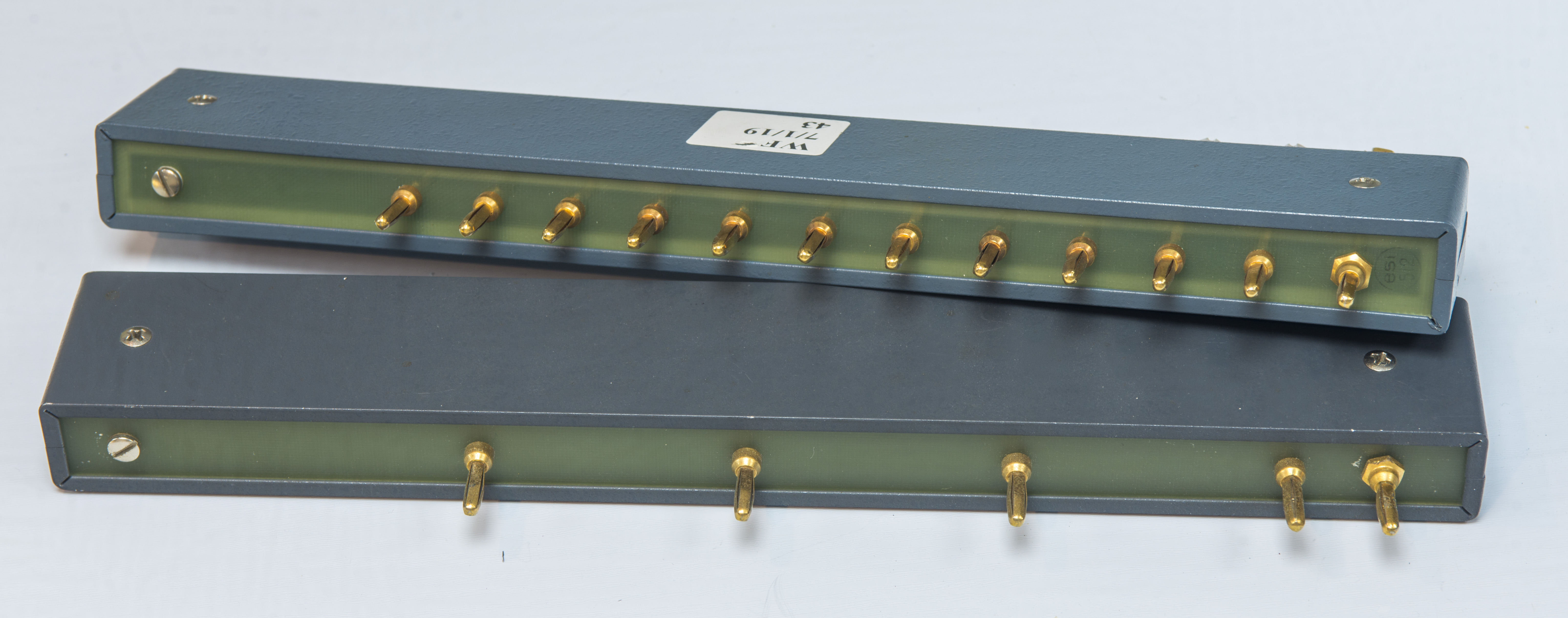
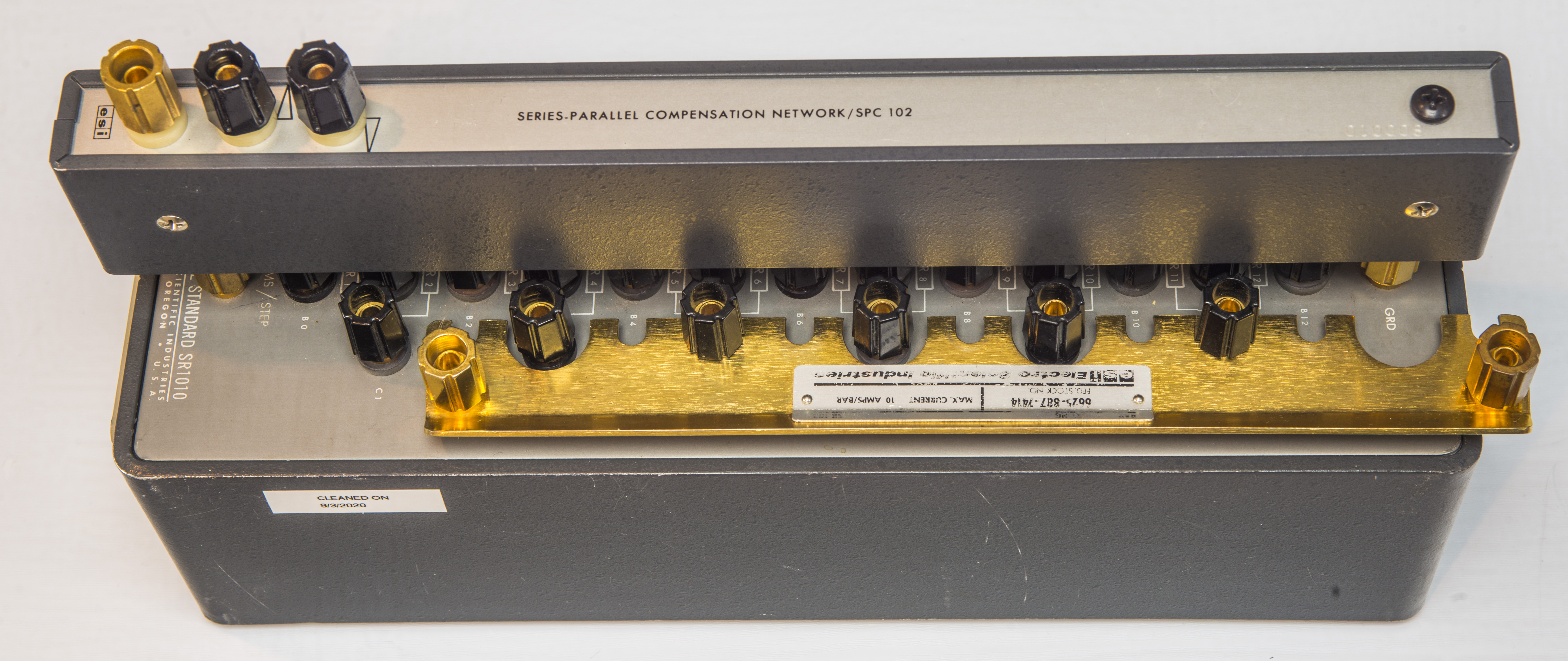
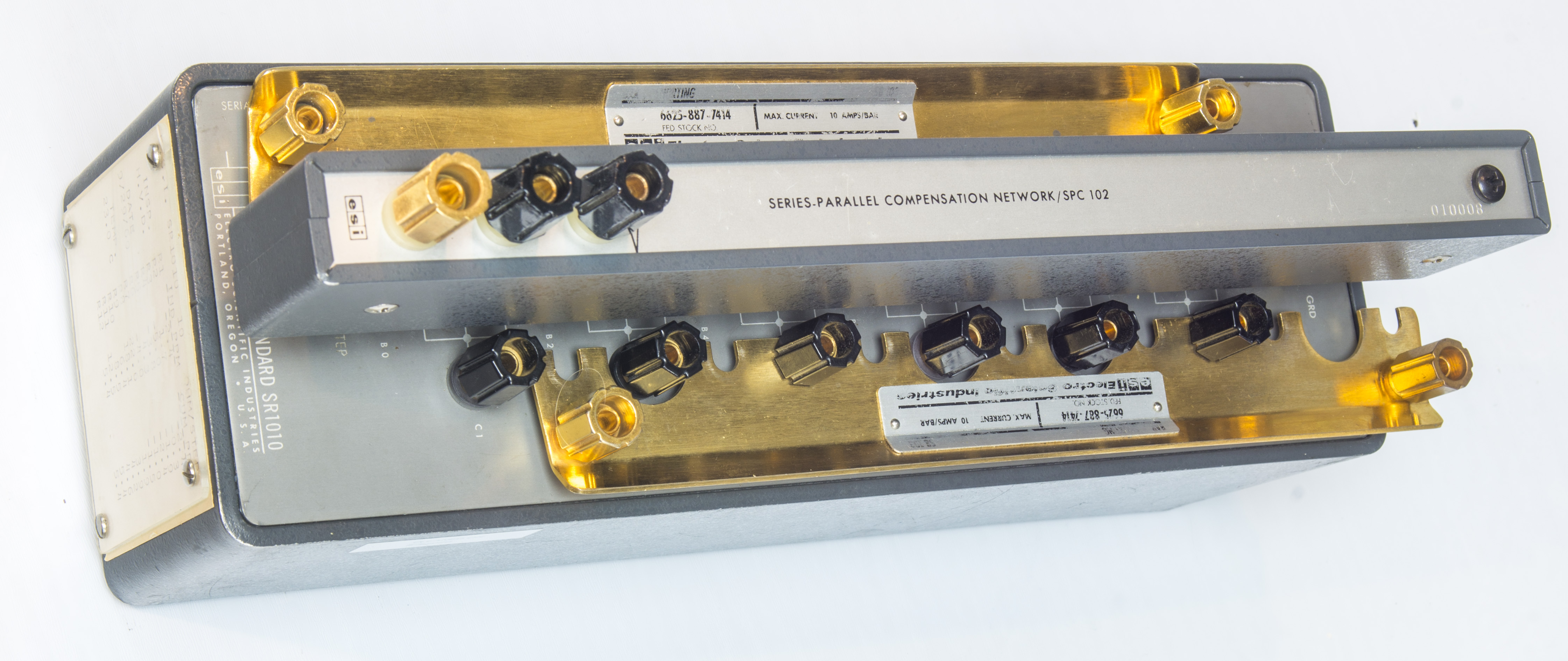
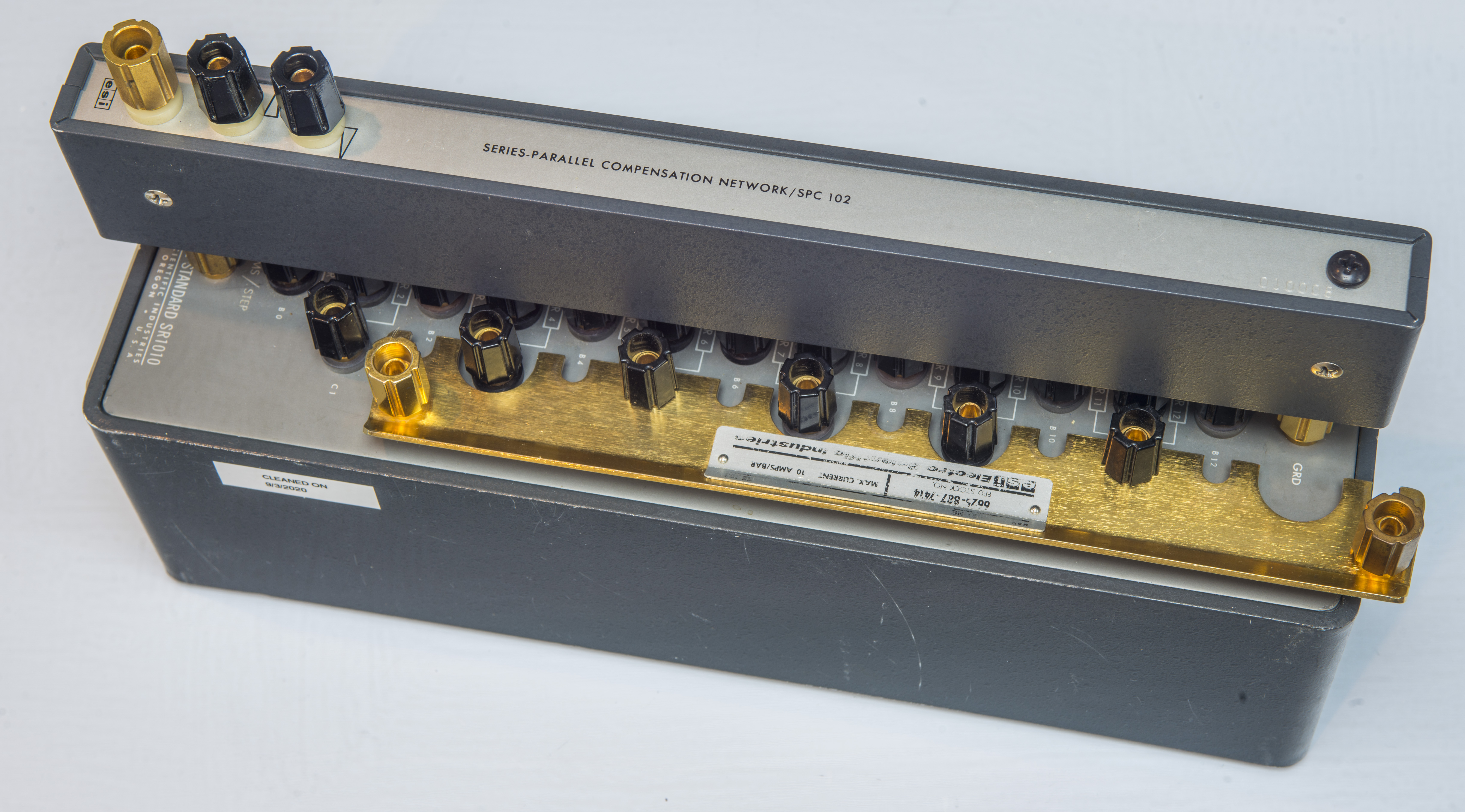
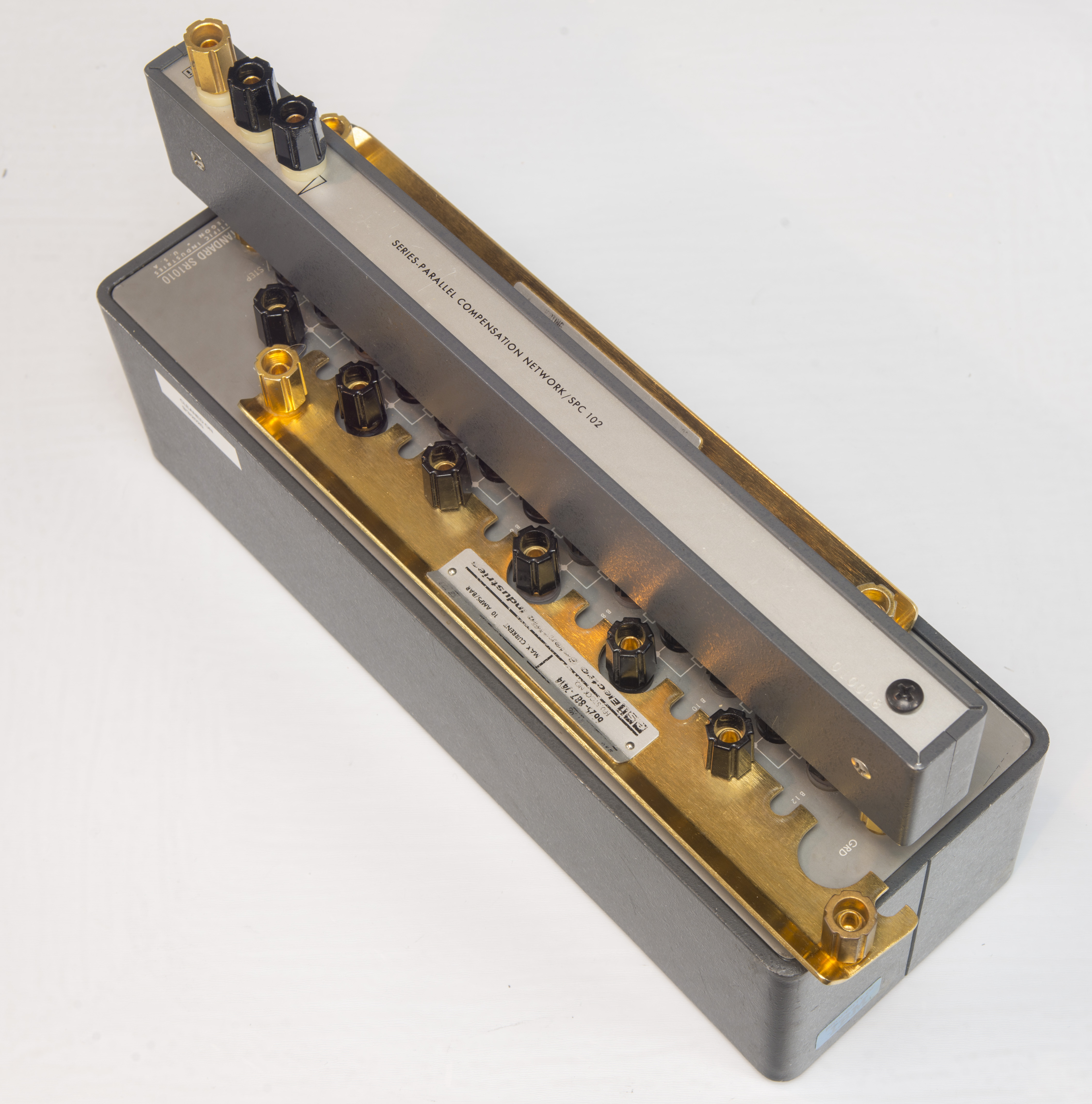
These transfer standards are boxes with 12 equal resistance elements. These form a divider with resistance steps in increments of 1 Ω (SR1010-1), 10 Ω (SR1010-10), 100 Ω (SR1010-100), 1 kΩ (SR1010-1k), 10 kΩ (SR1010-10k) and 100 kΩ (SR1010-100k) for 1010 series. Each element have kelvin four-terminal connections or support additional ratios with series and parallel combinations with optional Series-Parallel (SPC102), Parallel Compensation Networks (PC101) and shorting bars (SB103).
SR1030 is improved version of SR1010 with hermetical enclosure filled with oil. SR1050 are high-resistance models with switches instead of individual 4-wire taps.
Using resistance bridge systems such as ESI 242D or 242E these transfer standards can be very useful to verify and provide accurate decade calibrations for resistance standards. It is also handy tool to have as precision multi-tap voltage dividers when used in airbath to ensure stable thermal conditions. Today use of SR10×0 units is limited to budget metrology, as for high-end resistance measurements it is easier to use automated DC current bridges, such as Measurement International 6010/6000D or Guildline 6622A.
Manuals
ESI Resistance Standards, Instruments and Components, 1990 Catalog
ESI SR1010 Resistance Transfer Standard manual 1982
ESI SR1030 Resistance Transfer Standard manual 1991
ESI SR1050 Resistance Transfer Standard manual 1982
Tegam SR1010 Resistance Transfer Standard manual
Tegam SR1030 Resistance Transfer Standard manual
IET SR1050 Resistance Transfer Standard manual
Credits go to Ken Eckert for old manual scans, Thank you!
There are also special versions of these SR10*0 standards:
- LTC suffix – low thermal coefficient variant, with lower TCR per element
- MTB suffix – adjustable variant with trimpot array for fine-tuning
- X models – prototype and special custom units
ESI SR1010 100 Ω S/N
| Element | Calculated value at T=23 | Alpha TCR | Beta TCR | ZTCR point |
|---|---|---|---|---|
| R1 | 100.119329 Ω | α: -1.105 µΩ/Ω/°C | β: -0.015 µΩ/Ω/°C² | Zero TC: -14.0 °C |
| R2 | 99.9988623 Ω | α: -0.382 µΩ/Ω/°C | β: -0.029 µΩ/Ω/°C² | Zero TC: +16.4 °C |
| R3 | 99.999664 Ω | α: +0.781 µΩ/Ω/°C | β: -0.015 µΩ/Ω/°C² | Zero TC: +37.7 °C |
| R4 | 99.9989036 Ω | α: -0.392 µΩ/Ω/°C | β: -0.026 µΩ/Ω/°C² | Zero TC: +15.5 °C |
| R5 | 99.999105 Ω | α: -0.318 µΩ/Ω/°C | β: -0.022 µΩ/Ω/°C² | Zero TC: +15.8 °C |
| R6 | 99.99888 Ω | α: +0.027 µΩ/Ω/°C | β: -0.032 µΩ/Ω/°C² | Zero TC: +23.4 °C |
| R7 | 99.999461 Ω | α: +1.142 µΩ/Ω/°C | β: -0.025 µΩ/Ω/°C² | Zero TC: +45.6 °C |
| R8 | 100.00027 Ω | α: -1.993 µΩ/Ω/°C | β: -0.019 µΩ/Ω/°C² | Zero TC: -29.2 °C |
| R9 | 99.9997631 Ω | α: +0.719 µΩ/Ω/°C | β: -0.009 µΩ/Ω/°C² | Zero TC: +62.6 °C |
| R10 | 99.999936 Ω | α: -2.882 µΩ/Ω/°C | β: -0.018 µΩ/Ω/°C² | Zero TC: -55.8 °C |
| R11 | 99.9997072 Ω | α: -0.110 µΩ/Ω/°C | β: -0.026 µΩ/Ω/°C² | Zero TC: +20.8 °C |
| R12 | 100.00047 Ω | α: +0.136 µΩ/Ω/°C | β: -0.025 µΩ/Ω/°C² | Zero TC: +25.7 °C |
Temperature stability test of ESI SR1010 10Ω/step (non-LTC early unit), SN 348022
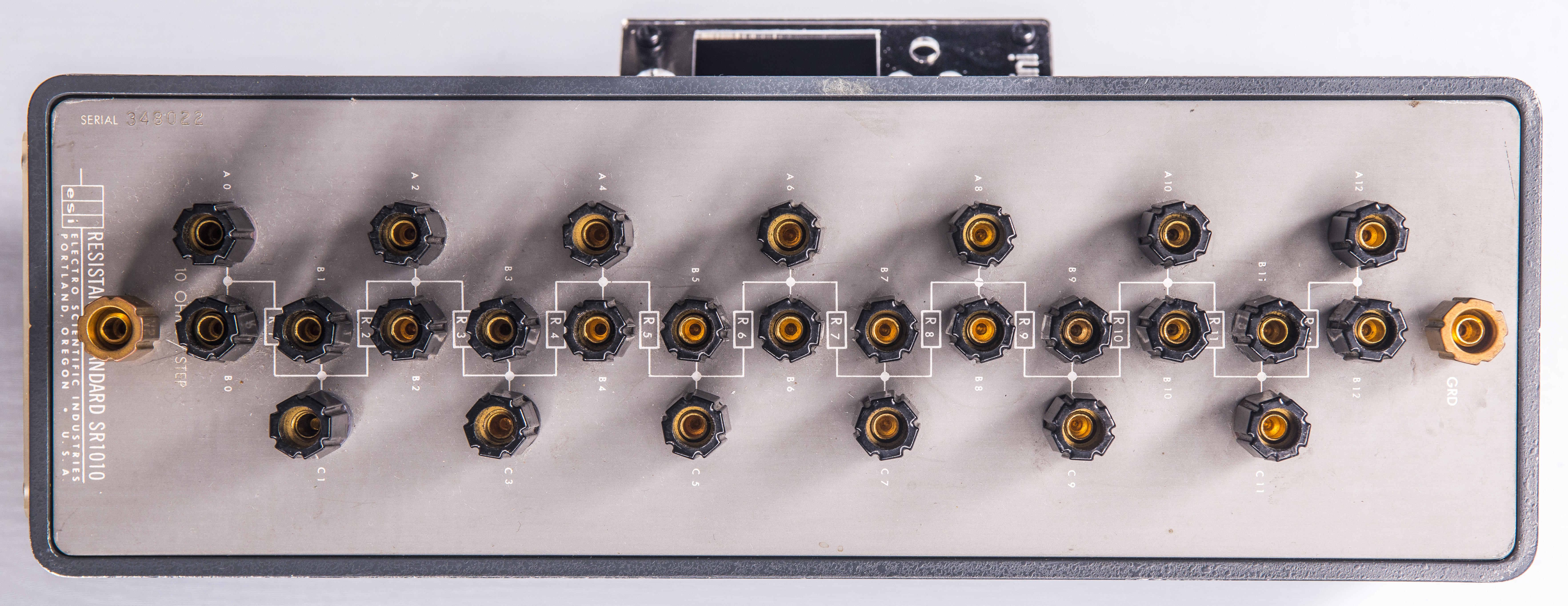
Resistor standard is packaged in nice sturdy metal enclosure with 5-way binding post. Based on label, this unit was manufactured and calibrated September 29, 1969. Almost exactly 51 years ago!


Each of SR10*0 resistance standards calibrated at factory to specifications and measurement results are attached to a side label. Label on this particular unit reproduced in table below. All benchmarks performed at standard +23.0 °C lab temperature, on 9/29/1969.
| ESI SR1010 10Ω/step, SN 348022 | Individual deviation | Cumulative deviation |
|---|---|---|
| R1 element | -2.4 ppm from nominal | -2.4 ppm from nominal |
| R2 element | +1.7 ppm from nominal | -0.3 ppm from nominal |
| R3 element | -5.0 ppm from nominal | -1.9 ppm from nominal |
| R4 element | -3.8 ppm from nominal | -2.4 ppm from nominal |
| R5 element | +4.3 ppm from nominal | -1.0 ppm from nominal |
| R6 element | -4.0 ppm from nominal | -1.5 ppm from nominal |
| R7 element | +22.6 ppm from nominal | +1.9 ppm from nominal |
| R8 element | +18.1 ppm from nominal | +3.9 ppm from nominal |
| R9 element | +6.4 ppm from nominal | +4.2 ppm from nominal |
| R10 element | +8.5 ppm from nominal | +4.6 ppm from nominal |
| R11 element | +12.5 ppm from nominal | +5.4 ppm from nominal |
| R12 element | +5.4 ppm from nominal | +5.4 ppm from nominal |

Air bath sweep from +18 °C to +30 °C.
Actual setup and instruments used for this test are shown on photo below. Method to measure temperature stability of each SR1010 element is to utilize precision high-stability calibrator (Fluke 5720A, calibrated August 25, 2020 against our traceable 1 Ω, 10 kΩ and 10 V standards) and array of 7½-digit and 8½-digit DVMs.
Calibrator sourced +11.00000 or -11.00000 mA DC current from AUX output into full 120 Ω resistance across ESI SR1010-10 and each DVM measure voltage drop (around 110 mV DC) on each element. Then resistance is calculated using ohm low.
To adjust temperature for dependency measurement DUT SR1010 placed in thermostat, which was controlled by TEC heater/cooler with help of Keithley 2510 TEC SMU. Internal thermostat temperature measured by Fluke 1529 Chub-E4 readout and Omega 100 Ω PRT 3-wire probe. Temperature change procedure:
- Soak 1 hour at +18 °C, wait for all readings to stabilize. This is our 0 ppm reference for all measurements now.
- Ramp temperature to +23.8 °C at slow rate +0.042 °C per minute
- Soak 30 minutes at this point for thermal delay check
- Ramp temperature to +29.5 °C at same rate
- Soak 1 hour for peak measurements
- Proceed with temperature ramp down, at inverse rate -0.042 °C per minute
All temperature coefficients calculated using box method ΔΩ/Δ°C.
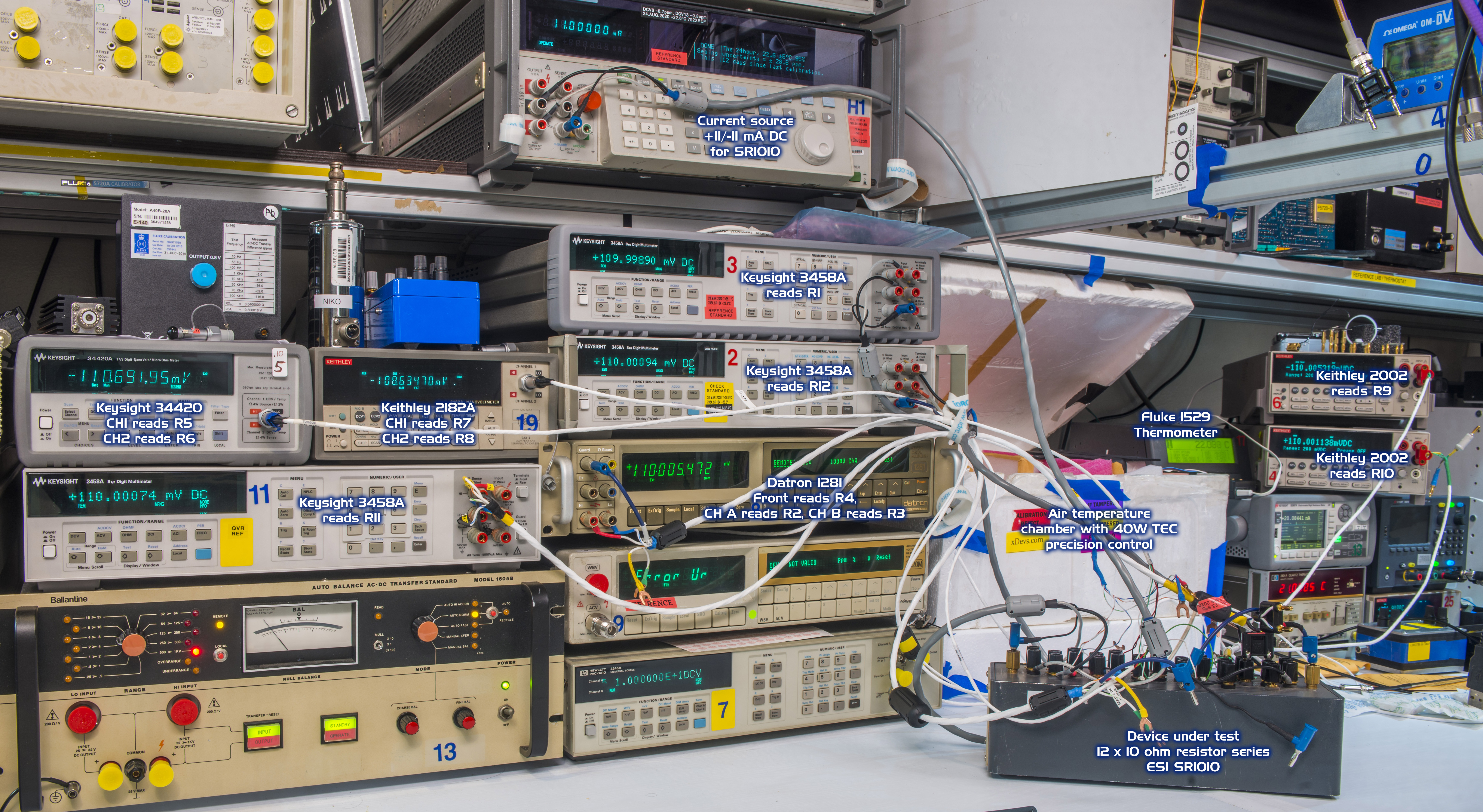
DUT ESI SR1010 is shown outside of thermal styrofoam box for clarity. During actual test divider was sealed in the chamber with 40W watercooled TEC device to provide precise and stable cooling and heating capability. All connections to digitizers waas done using low-thermal cables with spade lugs, except one cable routed to Datron 1281 front terminals.
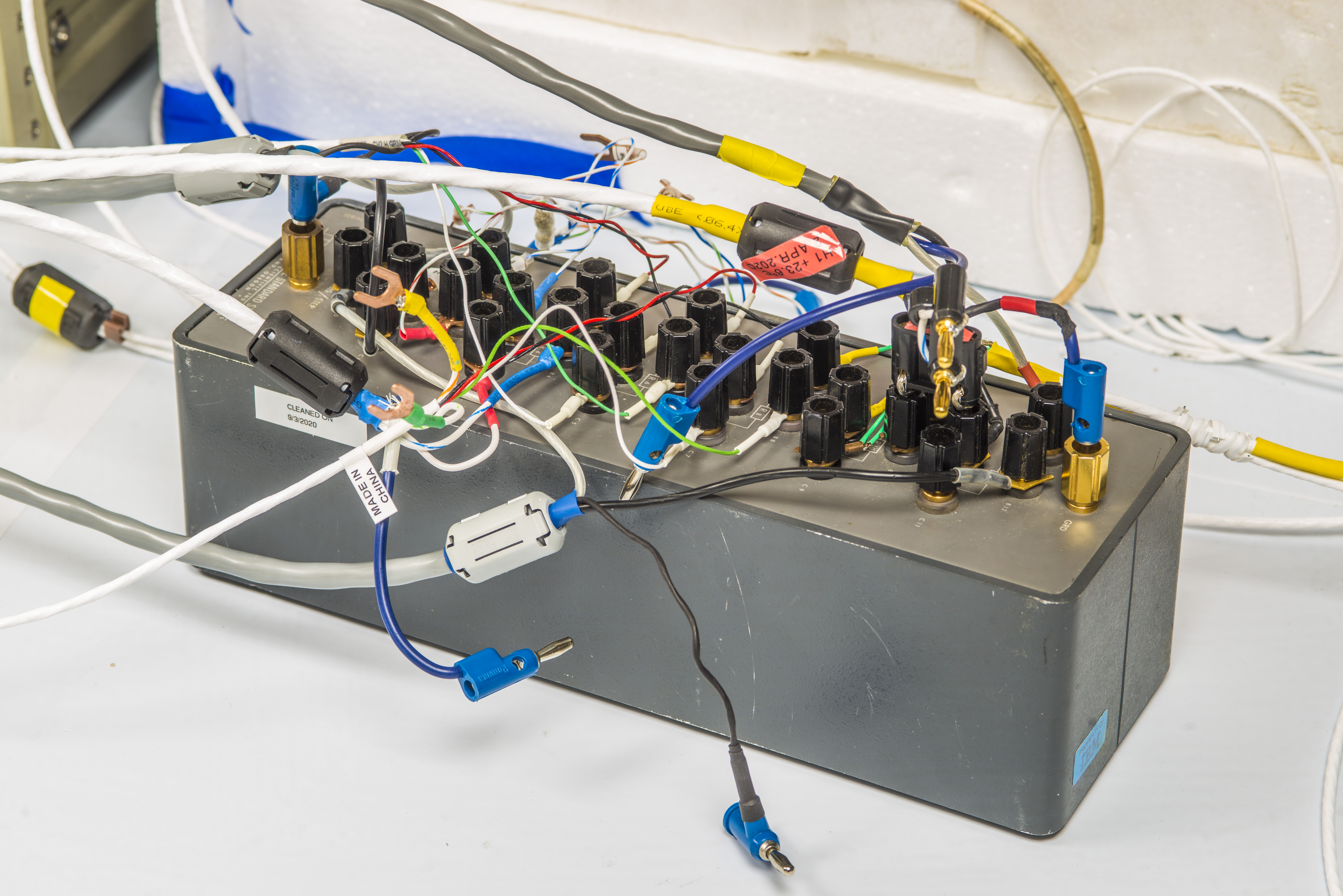
There is mixing fan to maintain air temperature uniformity. More details about chamber construction is shown in this article
Value columns legend and mapping is following:
- val1 = 3458A read ESI SR1010-10R element R1 , 120mV DC, NPLC50
- vbl5 = 1281 CH_A read ESI SR1010-10R element R2 , 200mV DC, RESL8 FAST ON
- vbl6 = 1281 CH_B read ESI SR1010-10R element R3, 200mV DC, RESL8 FAST ON
- val7 = 1281 Front read ESI SR1010-10R element R4 , 200mV DC, RESL8 FAST ON
- vbl2 = 34420A CH1 read ESI SR1010-10R element R5 , 120mV DC, NPLC50
- vbl4 = 34420A CH2 read ESI SR1010-10R element R6, 120mV DC, NPLC50
- val8 = 2182A CH1 read ESI SR1010-10R element R7, 120mV DC, NPLC5
- vbl1 = 2182A CH2 read ESI SR1010-10R element R8, 120mV DC, NPLC5
- val6 = 2002-6 read ESI SR1010-10R element R9, 210mV DC, NPLC20
- val4 = 2002-4 read ESI SR1010-10R element R10 , 210mV DC, NPLC20
- val3 = 3458C read ESI SR1010-10R element R11, 120mV DC, NPLC50
- val2 = 3458B read ESI SR1010-10R element R12, 120mV DC, NPLC50
- vbl3 = BME280 in box measure Pressure
- vbl8 = BME280 in box measure temperature
- vsvc = BME280 in box measure RH
Live plot page from D3.js library suite
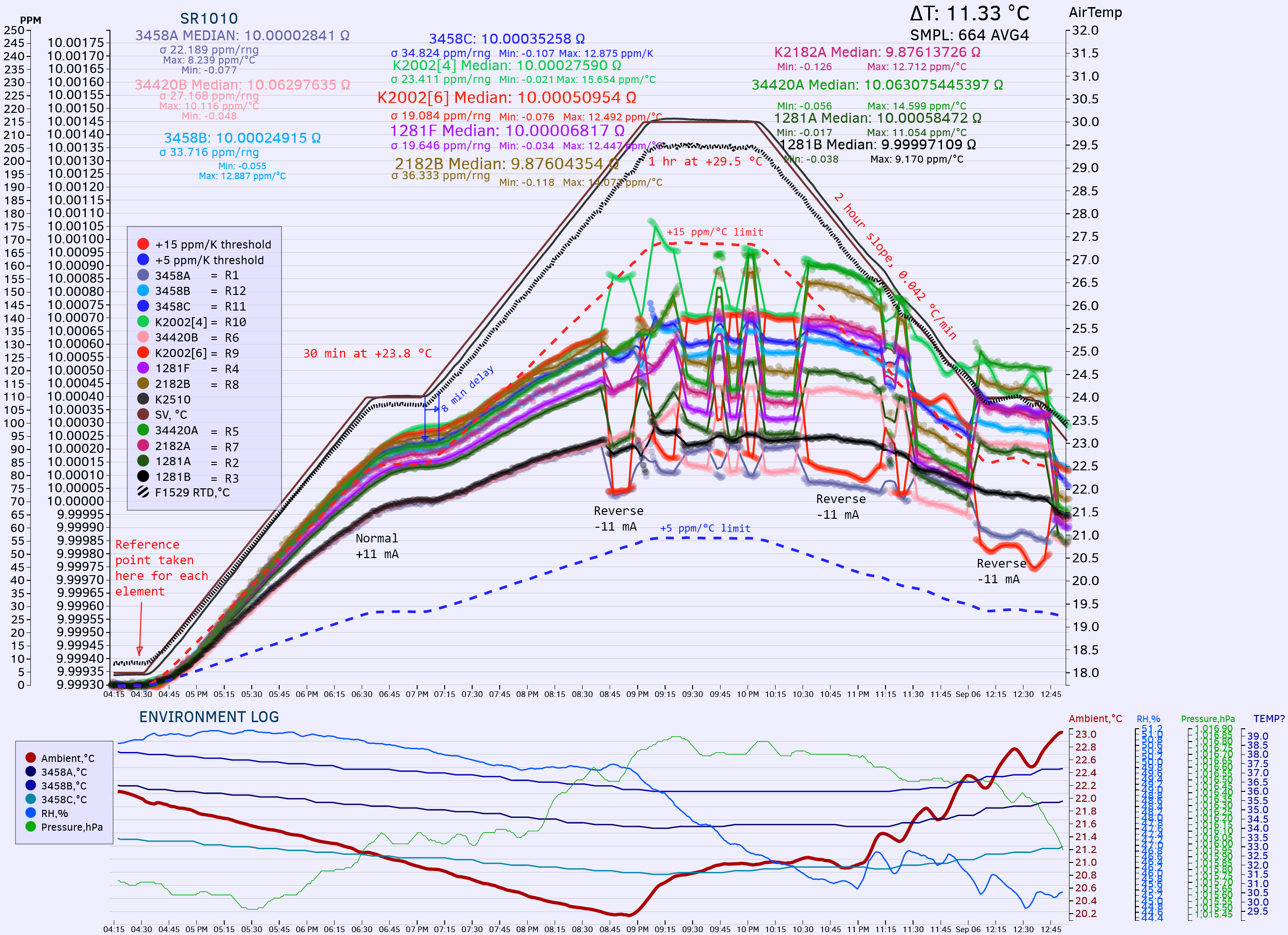
Jumps in plots are manual current reversal +11.000000 mA to -11.000000 mA and back at calibrator, to estimate Thermal EMF error
| _= Resistance Element | Minimum TCR | Maximum TCR | Median | Spread | Δ from median +11.02 ppm/°C |
|---|---|---|---|---|---|
| R1 | +6.3 ppm/°C | +8.3 ppm/°C | +7.3 ppm/°C | +2.0 ppm | -3.73 ppm |
| R2 | +8.3 ppm/°C | +11.1 ppm/°C | +9.7 ppm/°C | +2.8 ppm | -1.33 ppm |
| R3 | +8 ppm/°C | +9.2 ppm/°C | +8.6 ppm/°C | +1.2 ppm | -2.43 ppm |
| R4 | +9.2 ppm/°C | +12.5 ppm/°C | +10.9 ppm/°C | +3.3 ppm | -0.17 ppm |
| R5 | +9.7 ppm/°C | +14.6 ppm/°C | +12.2 ppm/°C | +4.9 ppm | 1.13 ppm |
| R6 | +7.4 ppm/°C | +10.1 ppm/°C | +8.8 ppm/°C | +2.7 ppm | -2.28 ppm |
| R7 | +9.7 ppm/°C | +12.7 ppm/°C | +11.2 ppm/°C | +3.0 ppm | 0.18 ppm |
| R8 | +10.6 ppm/°C | +14 ppm/°C | +12.3 ppm/°C | +3.4 ppm | 1.28 ppm |
| R9 | +7.2 ppm/°C | +12.5 ppm/°C | +9.9 ppm/°C | +5.3 ppm | -1.18 ppm |
| R10 | +12.3 ppm/°C | +15.6 ppm/°C | +14.0 ppm/°C | +3.3 ppm | 2.93 ppm |
| R11 | +11.5 ppm/°C | +12.9 ppm/°C | +12.2 ppm/°C | +1.4 ppm | 1.18 ppm |
| R12 | +10.7 ppm/°C | +12.9 ppm/°C | +11.8 ppm/°C | +2.2 ppm | 0.78 ppm |
Based on these measurements, we can estimate that thermal EMF error contributed maximum 5.3 ppm, and composite temperature stability between all resistors (median of all individual results) is +11 µΩ/Ω per °C which is much larger to specified ±1 µΩ/Ω per °C for SR1010LTC-10. Perhaps it is due to old design, which does not have suffix SR1010LTC. Such model for 10 &Omega/step is no even listed in the specification datasheets, where only LTC-version is specified for this step size.
Credits go to EEVblog member Nikonoid for this resistance standard benchmark and review.
Projects like this are born from passion and a desire to share how things work. Education is the foundation of a healthy society - especially important in today's volatile world. xDevs began as a personal project notepad in Kherson, Ukraine back in 2008 and has grown with support of passionate readers just like you. There are no (and never will be) any ads, sponsors or shareholders behind xDevs.com, just a commitment to inspire and help learning. If you are in a position to help others like us, please consider supporting xDevs.com’s home-country Ukraine in its defense of freedom to speak, freedom to live in peace and freedom to choose their way. You can use official site to support Ukraine – United24 or Help99. Every cent counts.
Modified: Jan. 23, 2025, 7:49 p.m.