Introduction
Friend of xDevs.com project Steve found and shared to us some rare unknown Keithley box listing. As admirers of Keithley instruments, particularly the older models that are accompanied by comprehensive service manuals, detailed theory of operation, and exceptional design quality (except leaking caps in 2001/2002 ;)), we couldn’t resist the temptation to add this mystery box to our voltmeter collection. The surplus equipment business, Solano Traders, kindly accepted our reasonable offer, and after a few days, the box was delivered to us for tear-down and experimentation purposes.
Disclaimer
Redistribution and use of this article, any parts of it or any images or files referenced in it, in source and binary forms, with or without modification, are permitted provided that the following conditions are met:
- Redistribution of this article must retain the above copyright notice, this list of conditions, link to this page (https://xdevs.com/article/kei_vm02/) and the following disclaimer.
- Redistribution of files in binary form must reproduce the above copyright notice, this list of conditions, link to this page (https://xdevs.com/article/kei_vm02/), and the following disclaimer in the documentation and/or other materials provided with the distribution, for example Readme file.
All information posted here is hosted just for education purposes and provided AS IS. In no event shall the author, xDevs.com site, or any other 3rd party, including Keithley/Tektronix be liable for any special, direct, indirect, or consequential damages or any damages whatsoever resulting from loss of use, data or profits, whether in an action of contract, negligence or other tortuous action, arising out of or in connection with the use or performance of information published here.
If you willing to contribute or add your experience regarding instrument repairs or provide extra information, you can do so following these simple instructions
Exterior and video review
Coming soon™…
This voltmeter is quite small, shorter and just about the side of the A/D 3458A A3 PCB.
Teardown and internal design analysis
Enclosure held together by two aluminum brackets with brackets and four screws. Hefty metal cover slides off easily, allowing quick and easy access to internal PCB.
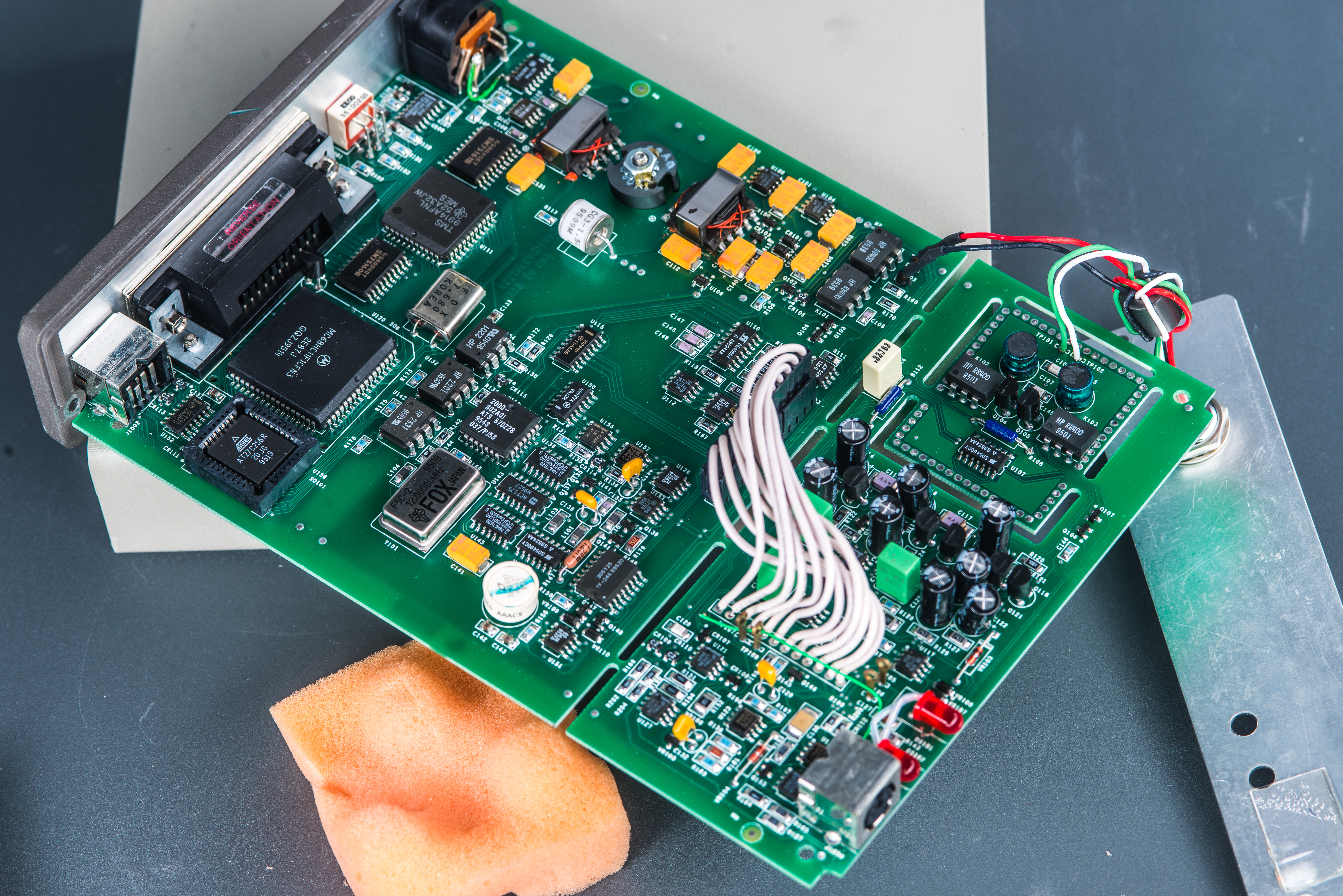
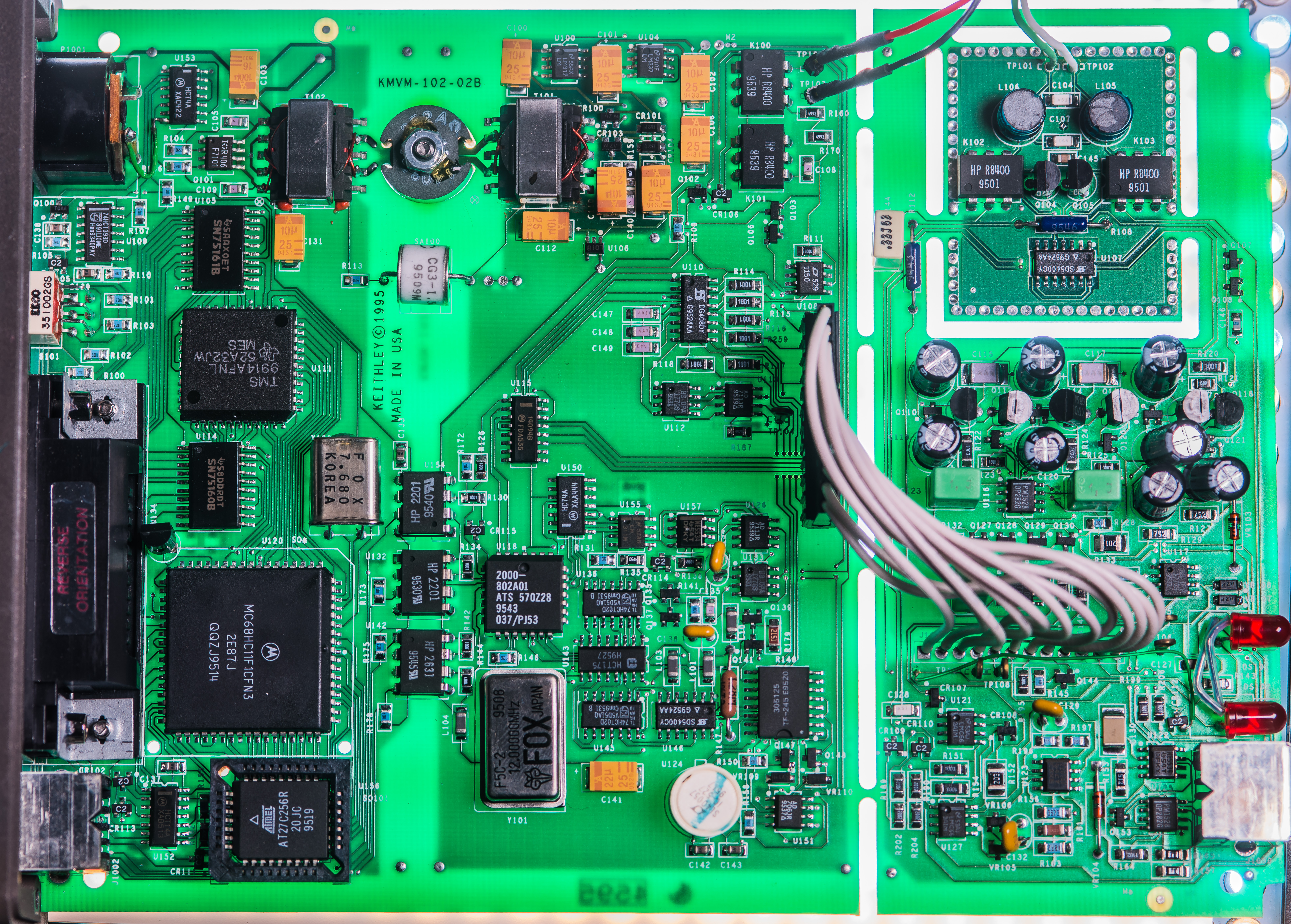
Compact circuit board exhibits a well-organized layout featuring several recognizable Keithley circuit blocks. By examining the PCB date codes, we can deduce that the design and manufacture of the board took place approximately around 1995. This information provides valuable insights into the historical context and time frame of this Keithley product, placing it before 2182 design years.
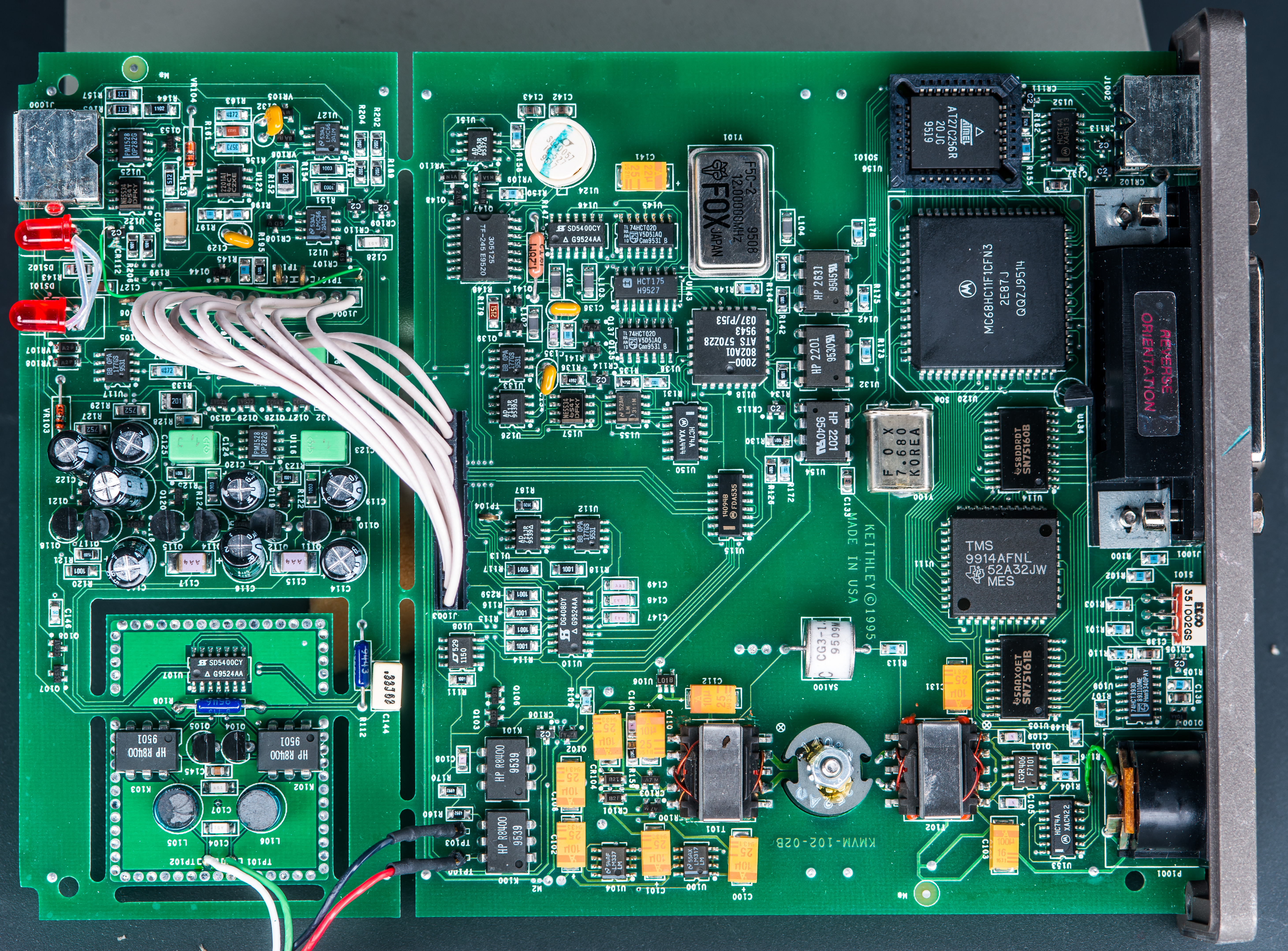
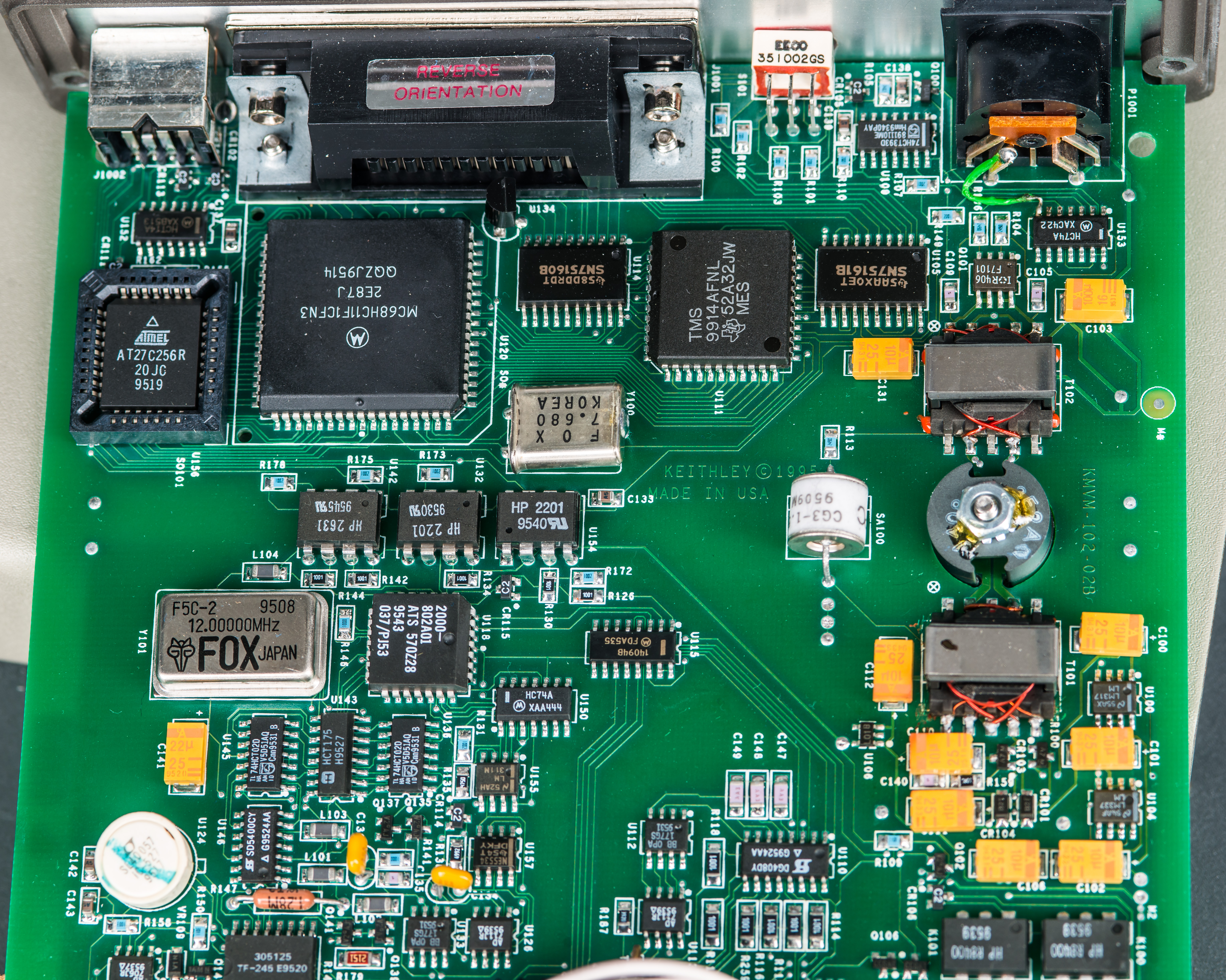
From the first glance we can spot main digital domain with traditional Motorola MC68HC11F1CFN3 microprocessor with AT27C256R program OTP EPROM and some logic around. Texas Instruments TMS9914AFNL is typical implementation of GPIB IEEE-488 bus controller interfacing standard GPIB connector via standard TI SN75160B and SN75161B drivers. Little rotatory switch S101 provide way for user to configure GPIB address in a limited range from 0 to 9. I don’t see the expected I2C EEPROM for serial number and calibration data storage, perhaps Keithley stored that data internally in microprocessor’s EEPROM? MC68HC11F1 has 512 bytes of internal EEPROM so this theory might be true.
The instrument receives power exclusively through the DC jack P1001, which is of the DIN-5 type. The handwriting on the back bezel indicates that it requires a single +5V external power supply. At the PCB level, pins 1 and 2 are shorted together, while pins 4 and 5 are connected to the ground return. Additionally, there is a small green mod-wire that connects the ground from pin 4 of DIN-5 receptacle to the VSS pin 7 of the U153 logic chip, specifically the 74HC74A.
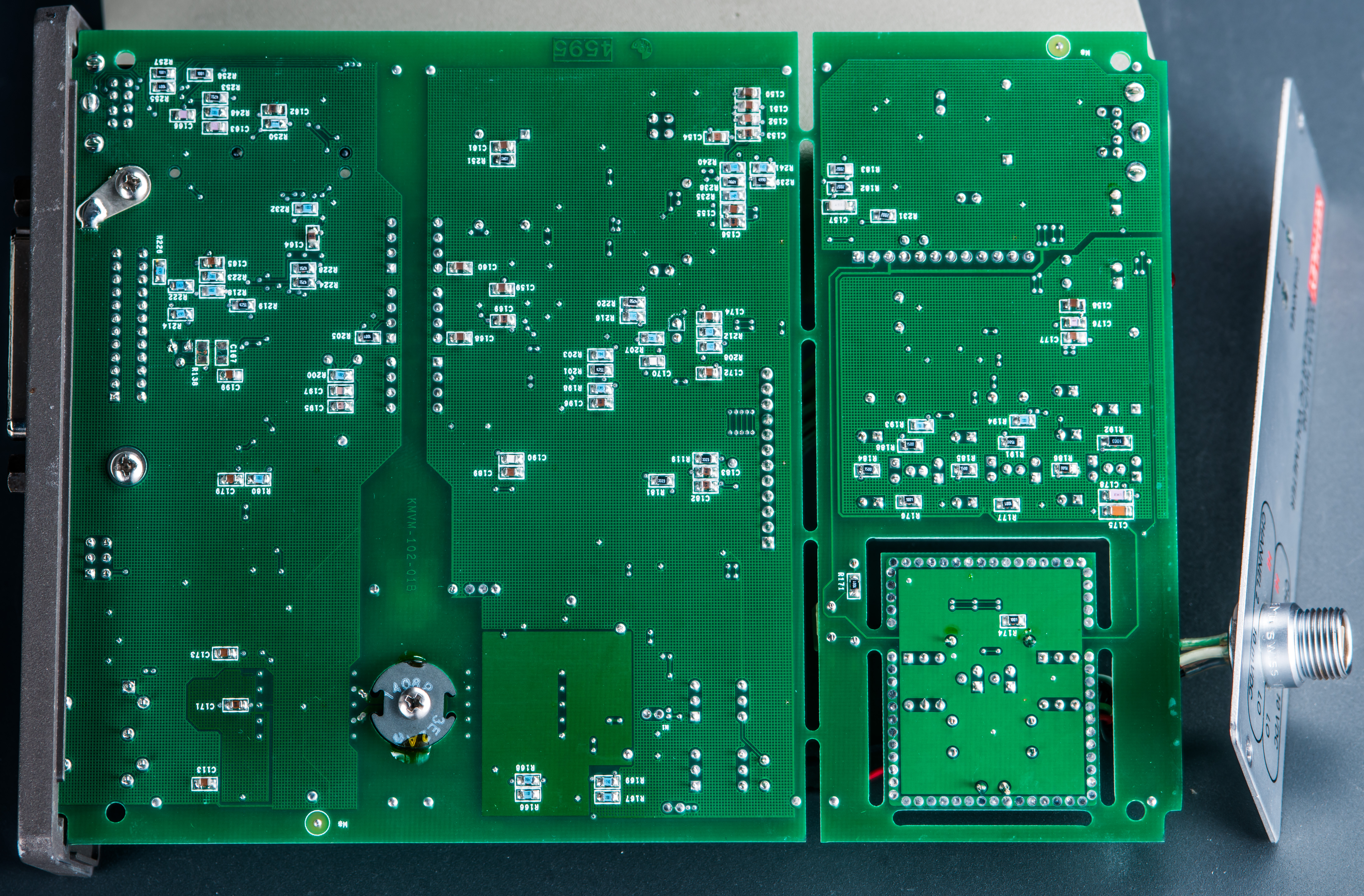
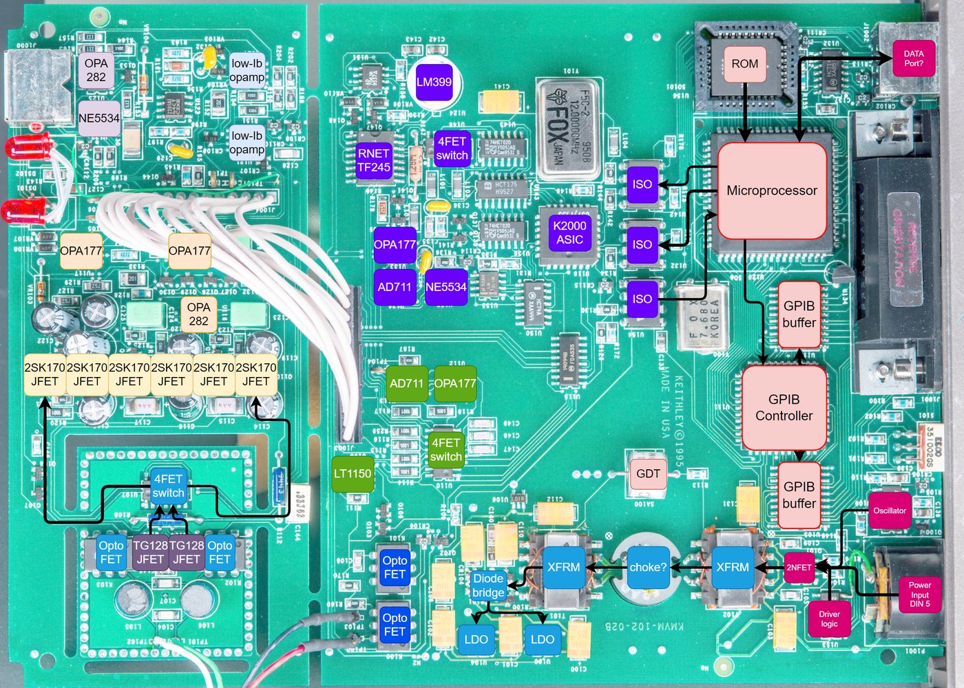
Bottom side shows clearly separated power and isolation domains of the whole instruments. This is 2-layer PCB, so reverse engineering it would be not difficult job perhaps for just few days. Even without detailed RE we can guesstimate functional purpose of most circuits around.
Based on just these two photos we can determine topology of this instrument on map below:
Front panel marking hints two input channels, with different voltage ranges. Channel 1 designed to accept 10 VDC signals. Second channel marked 10 mV DC. Interesting question would be to see if there are any other ranges available internally? This instrument has just two red 5mm LEDs to indicate currently selected channel and no other user interface features.
KM-VM-10V7-02 is obviously designed for integration into larger systems such as automated test equipment setups with computer controlled operation. It is quite elegant way to get high performance digitizer without paying for all extra hardware in volumetric space and money. Keithley (today Tektronix) manufacture such integration-purpose instruments even today. Most notable modern examples of such products are dual 7½-digit DMM7512, quad-channel SMU 2606B, system DMM with front-panel delete options, such as Keithley DMM7510-NFP, 2450-NFP, 3706A-NFP and many others.
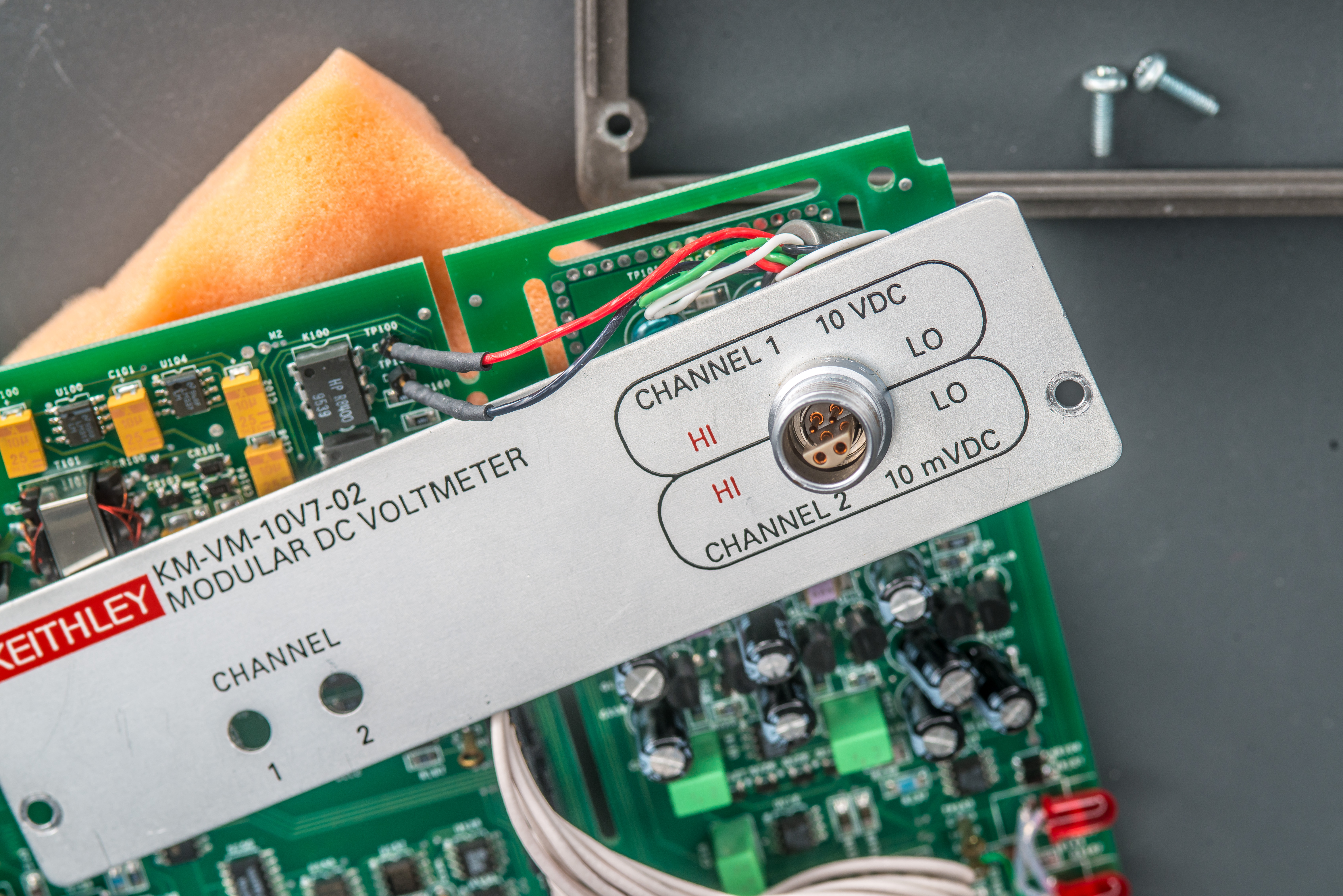
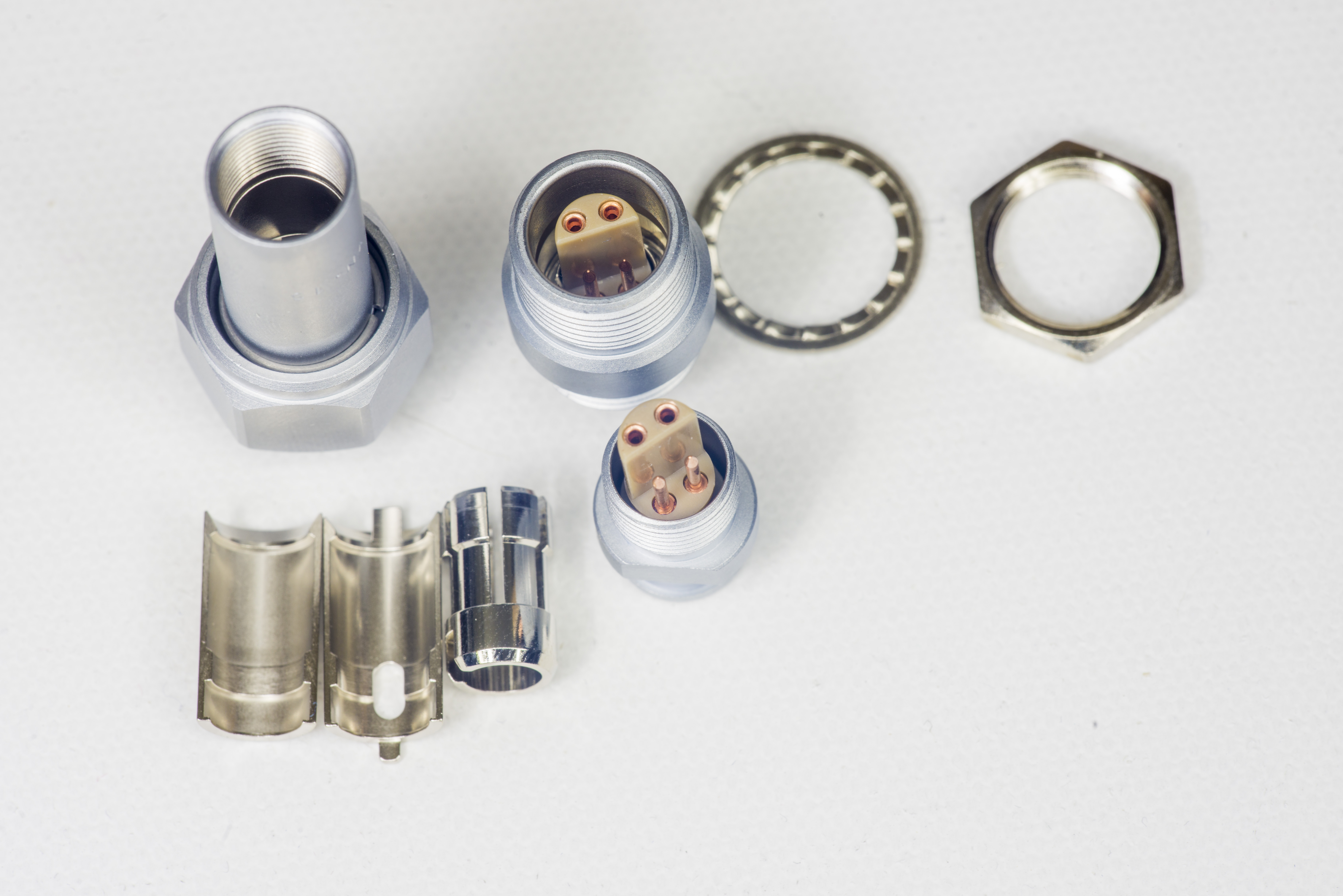
On the front panel plate we can also find very nice and expensive no BS-plating copper only LEMO EVP.1S.304.CLY input connector. I have purchased these connectors before and they are one of the nicest low-thermal interfaces commercially available. Very same connector is also used in Keithley 2182/2182A and HP/Agilent/Keysight 34420A nanovoltmeters.
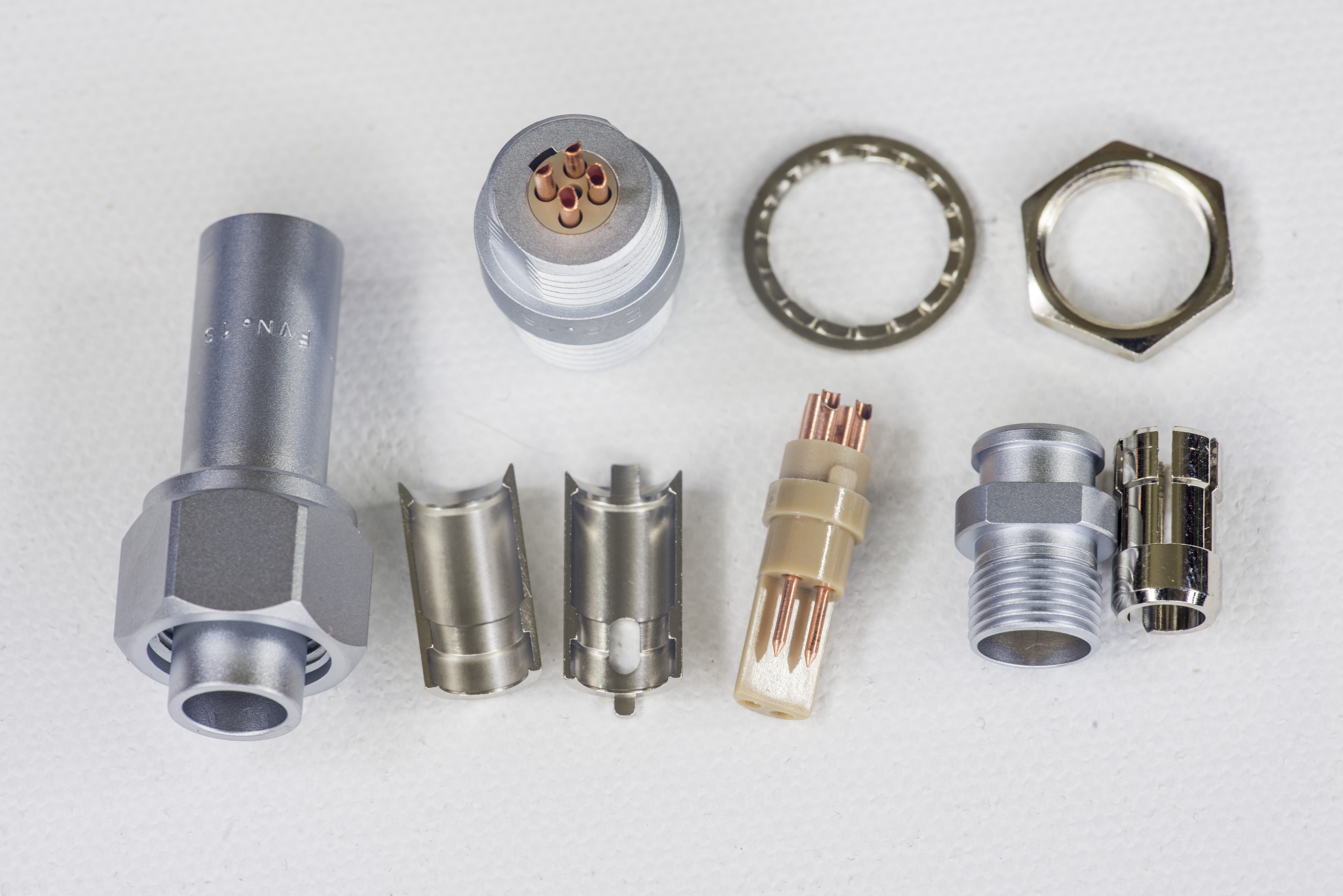
These connectors have brass body and UNC C18700 99.5% copper terminals. Insulator around pins is mechanically rugged PEEK which is also quite good thermal insulator.
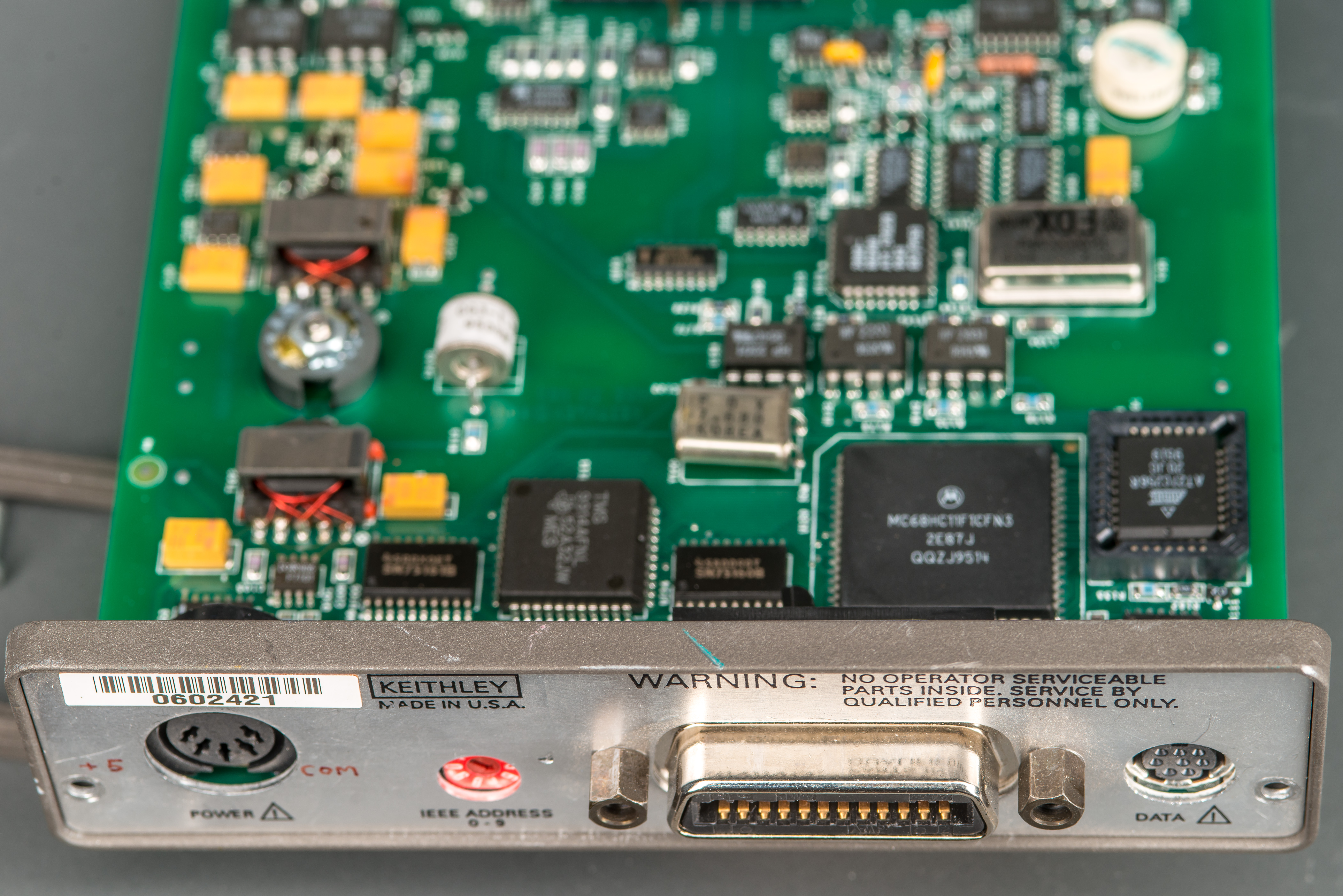
Presence of serial number label hints that these KM-VM instruments were not some internal lab prototype but actually sold product. There is unusual mini-DIN 8 pin receptacle next to GPIB, probably for trigger or status communication? Usual benchtop instruments often had trigger-link interface available with this formfactor type.
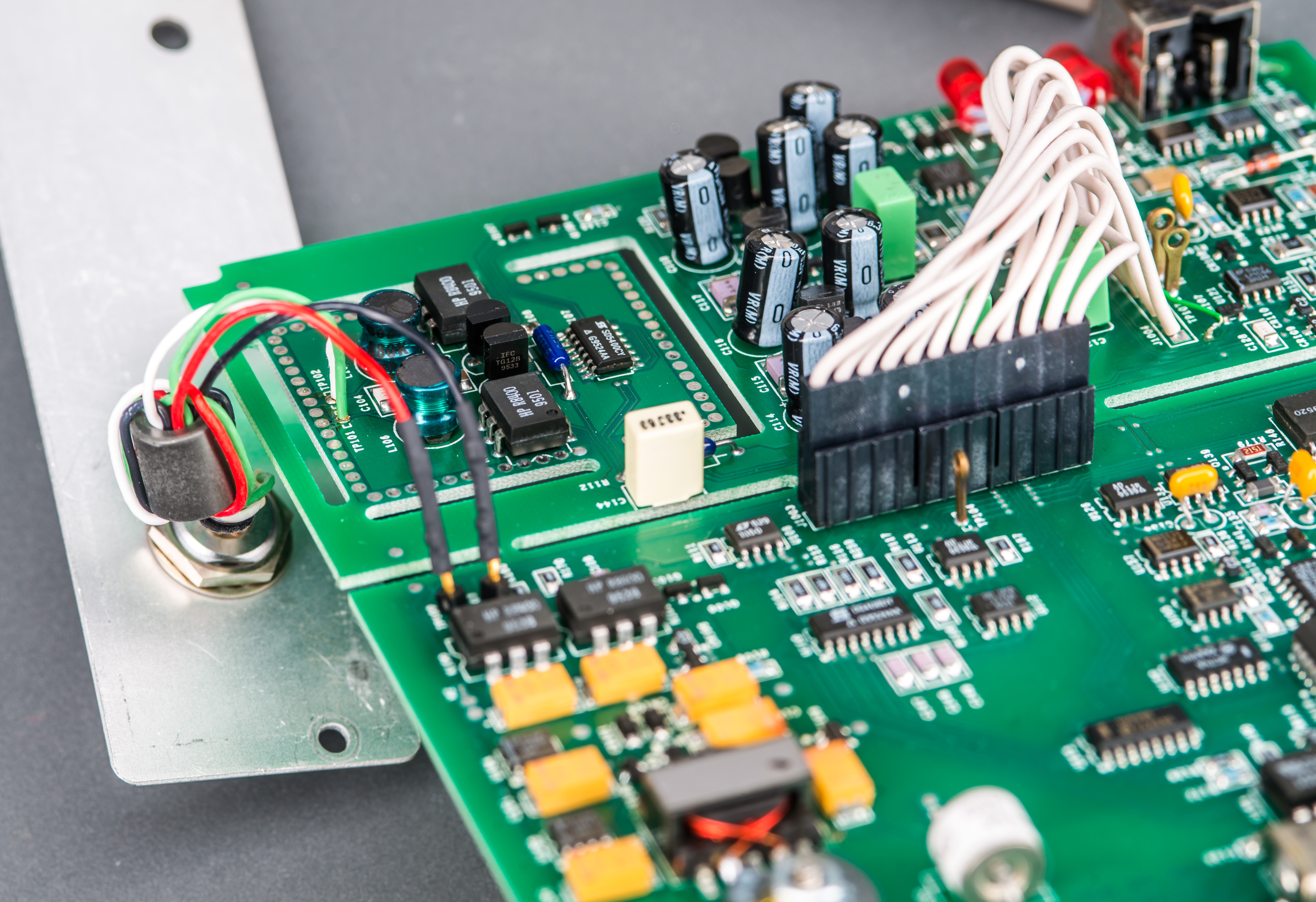
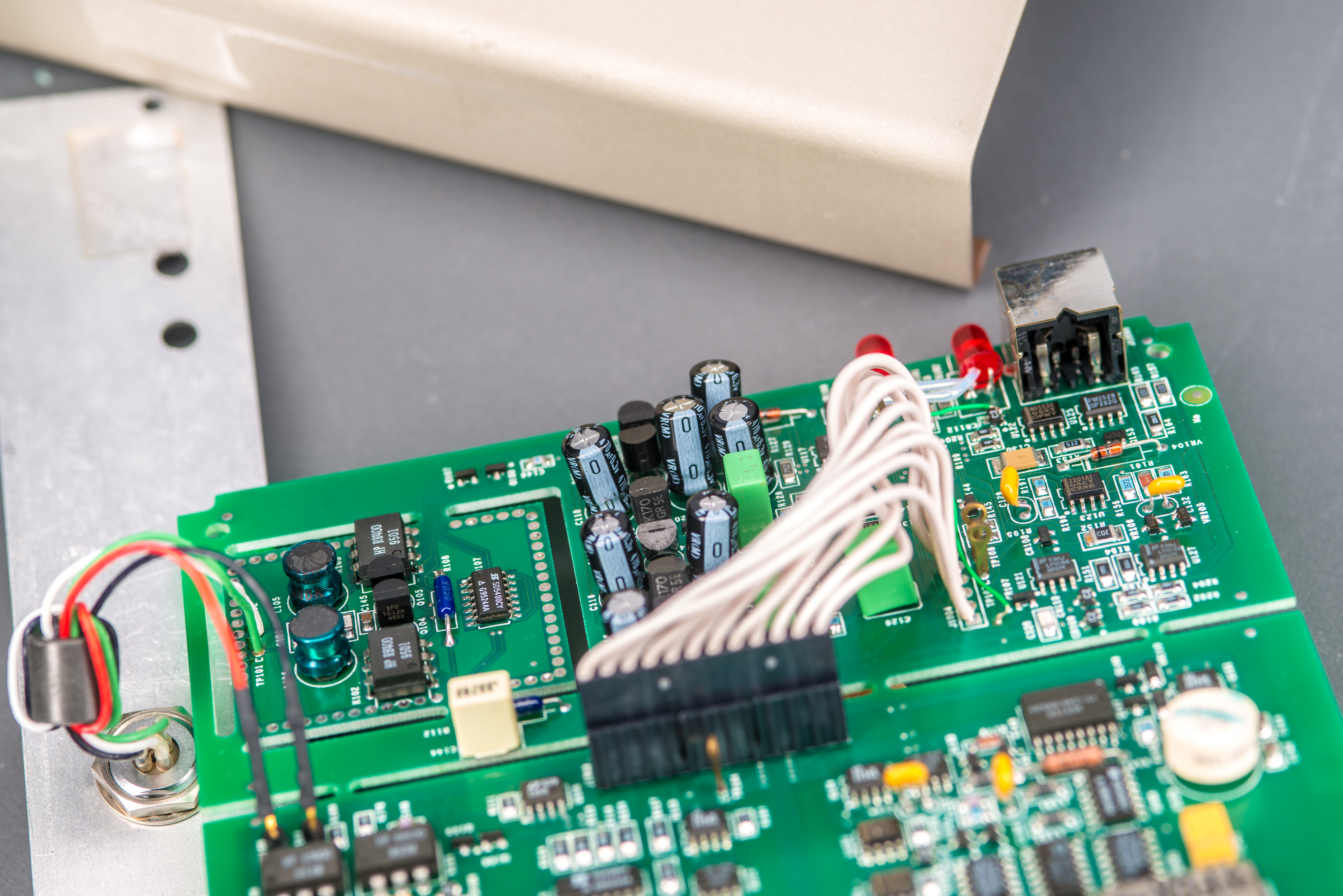
Sensitive channel 2 is connected directly to PCB’s test points at floated section of the further separated front of the board. Input is routed thru two large ferrite chokes to HP HSSR-8400 high voltage opto-SSR. Additional foamed insulator was covering this isolated island for CH2 front end input. There is no fan to generate airflow inside KM-VM but thermal gradients could still cause small air movement which would translate into small variations of sensitive circuit temperature. Due to thermal EMF effect even tiny temperature changes would directly translate into added very low frequency noise in measurement path. Because of this great attention to thermal management is paramount for any microvolt-type DC voltage amplifier front-end.
These SSRs have very low Ron around 6 Ω and can operate with hefty currents over 150mA. These switches also not fast with turn-on time around 1ms. They do provide quite high isolation around 100 G&Omega and typical 1pF input-output capacitance. Using solid-state switches is common in sensitive nano-voltmeter front ends to provide modulation/demodulation of DC signals and remove 1/f noise from the signal of interest.
Next to these large SSRs we can find Keithley-specific pair of IFC TG128 JFET in TO-92 package with two PTF56 precision resitors and quad FET Siliconix SD5400CY. Today SD5400 is manufactured and supported by Linear Systems who is a market leader in specialty low noise and low leakage discrete devices.
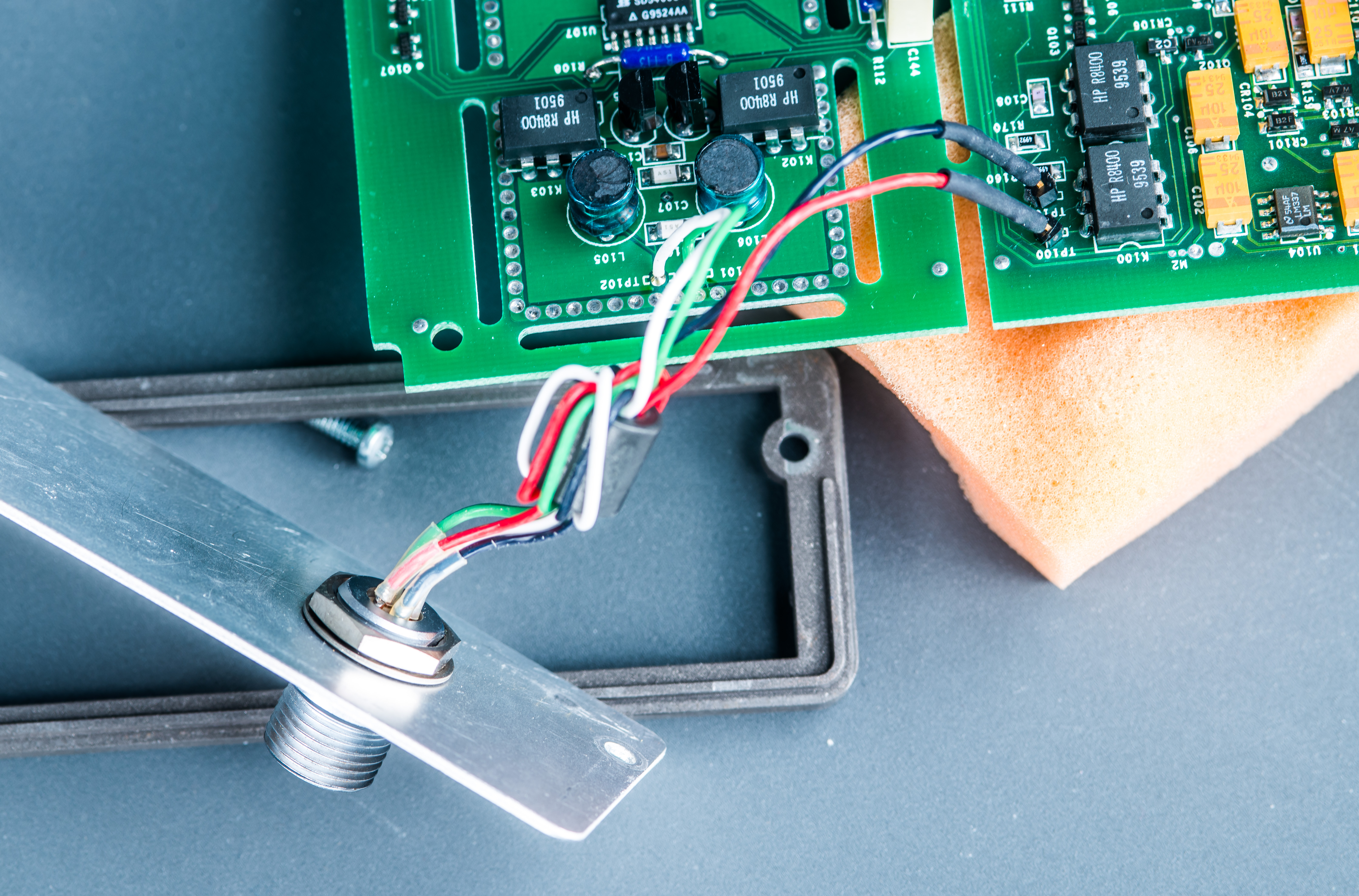
Channel 1 black and red wires are plugged into standard 2.54mm pitch header pins. Cable from input connector have additional ferrite common mode choke in place to catch some fast interference transients. There is no thermal sensor next to connector unlike more modern Keithley 2182/2182A nVM.
All earth-referenced digital electronics is powered by main input +5 VDC power source without any additional regulators or power conversion. Without inguard floating front end and it’s transformer based DC-DC converter power consumption of digital stuff is around 270 mA from +5.000 VDC source connected.
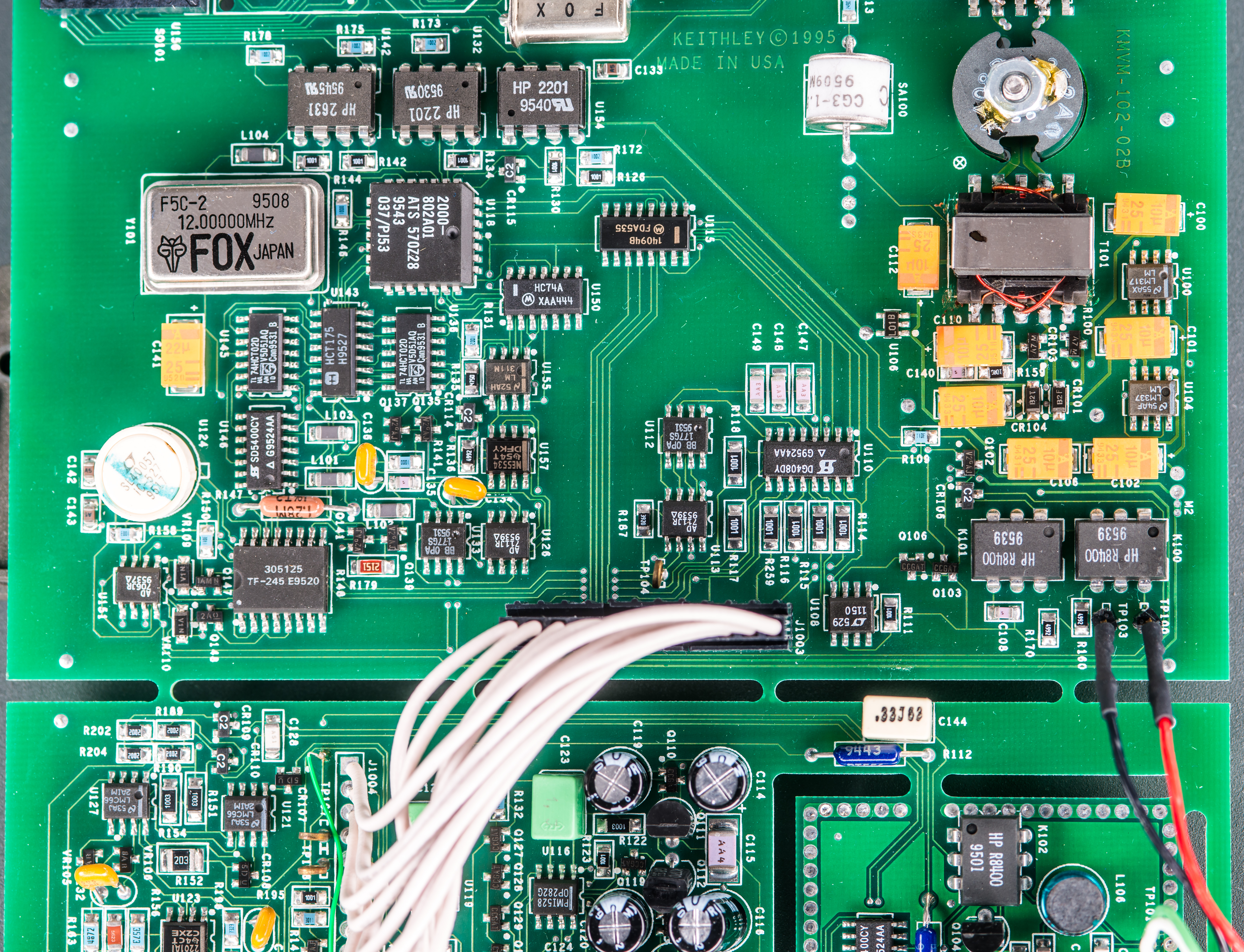
ADC core of this instrument is multislope converter reused from 6½-digit DMM Keithley 2000. Oldest implementation of such ADC is using ALTERA MAX CPLD and few external components, but later versions like we see in this KM-VM use customized Keithley ASIC in much smaller PLCC package. It is pretty decent design, supporting ±12 VDC inputs on base range and have performance similar to HP 34401A.
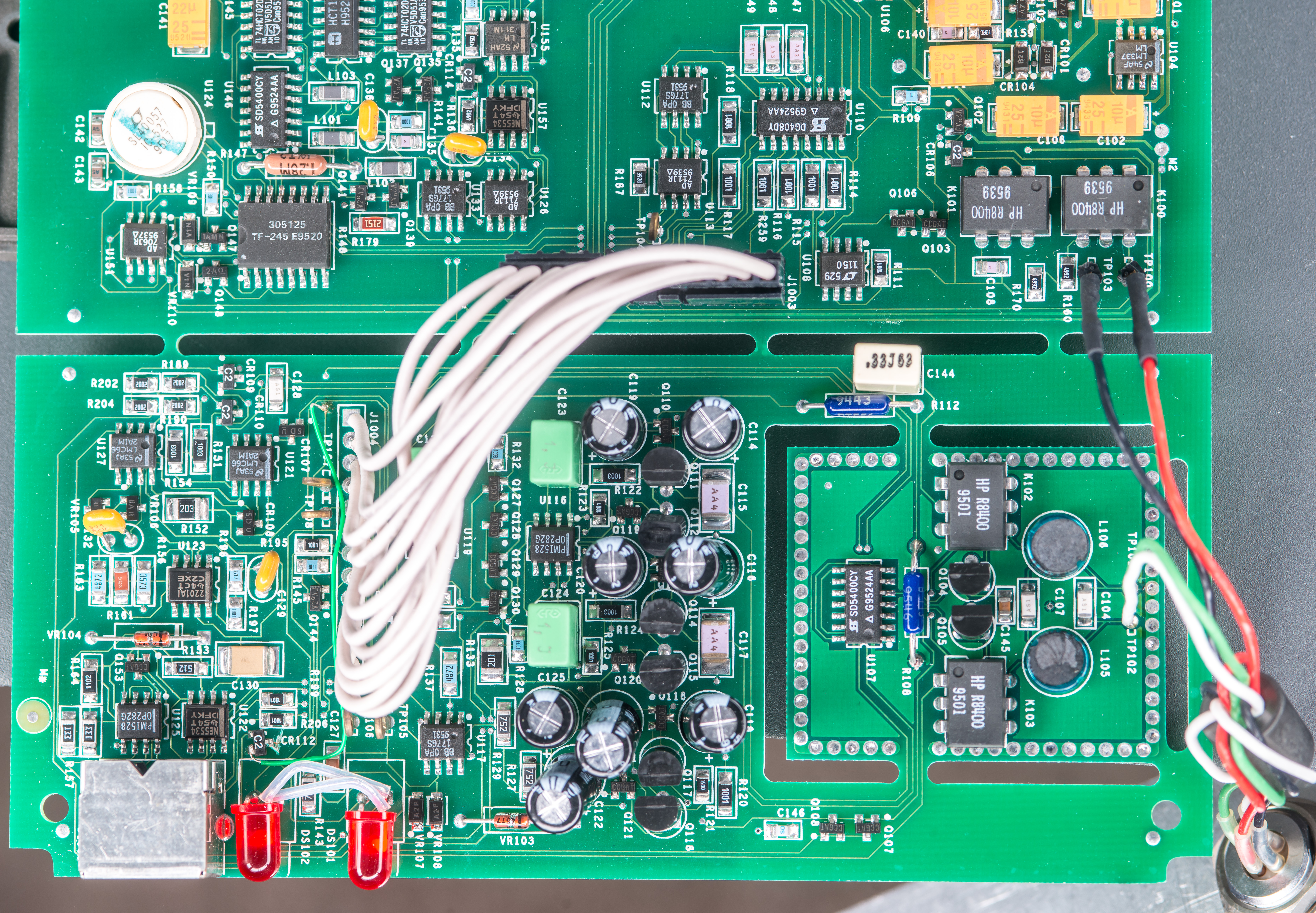
Low noise channel 2 front end is placed on fully isolated PCB section in front of the mainboard. Maybe at some point it was expected to be detached and placed externally to the actual digitizer electronics similar to how it’s done in Keithley 6430 or 4200 parametric analyzer systems? Only electrical connection between this section and main ADC/digitizer is with array of white insulator wires. There is populated mini-DIN 6 pin connector next to channel indicator LEDs but it is blocked by front panel metal plate and not normally accessible to user. Plastic pad is attached to front panel metal in the area next to this mini-DIN port to avoid metal contact.
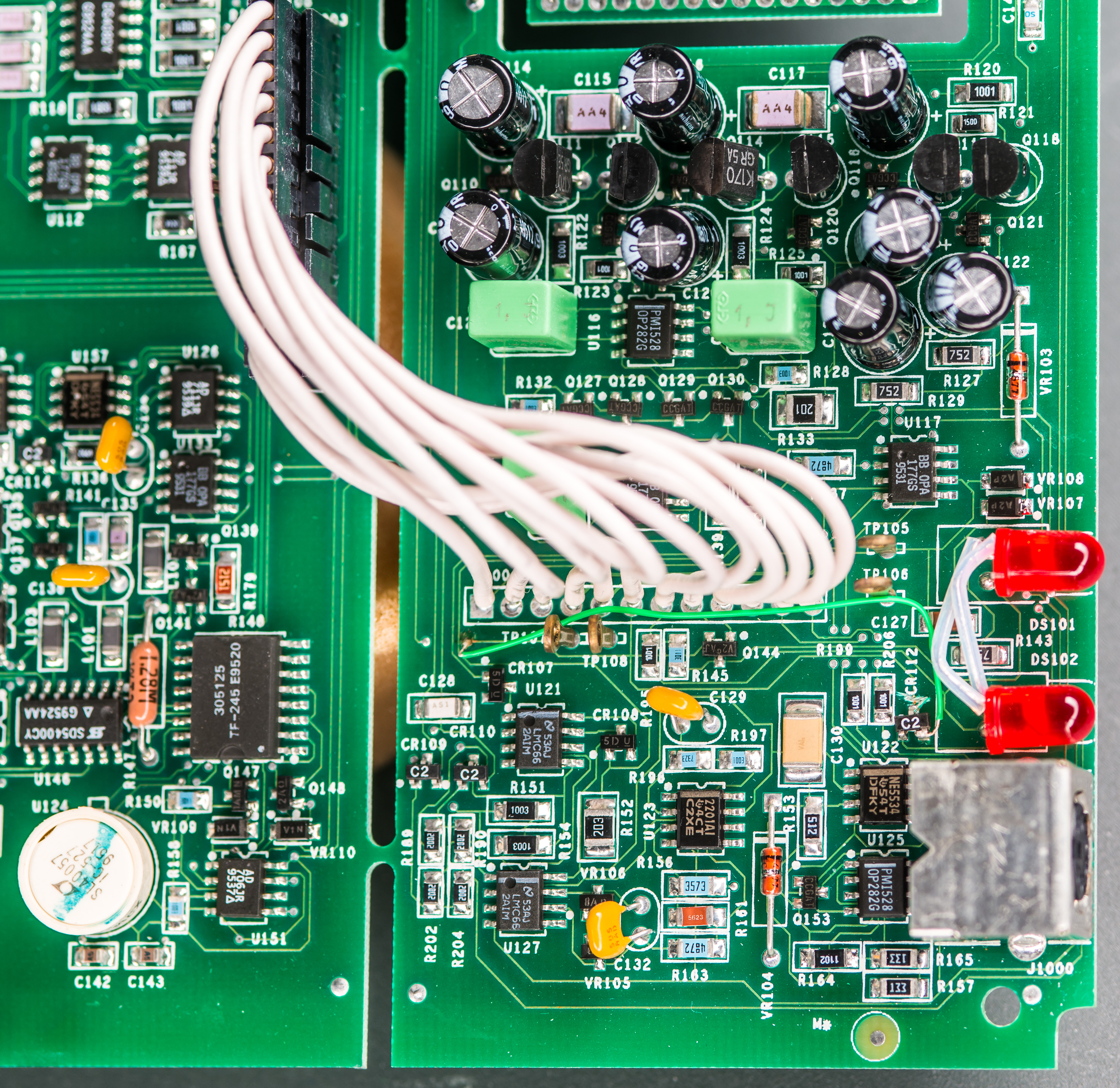
Sensitive measurements are quite demanding for good power supply solution with demanding isolation requirements. Many nanovoltmeters use floating power or even batteries to solve the power delivery problems, especially in noisy environments. Here Keithley also designed interesting looking isolated power regulator with 74HCT393D counter, 74HC74 Dual FF and obsoleted IRF7101 Dual NMOS HexFET
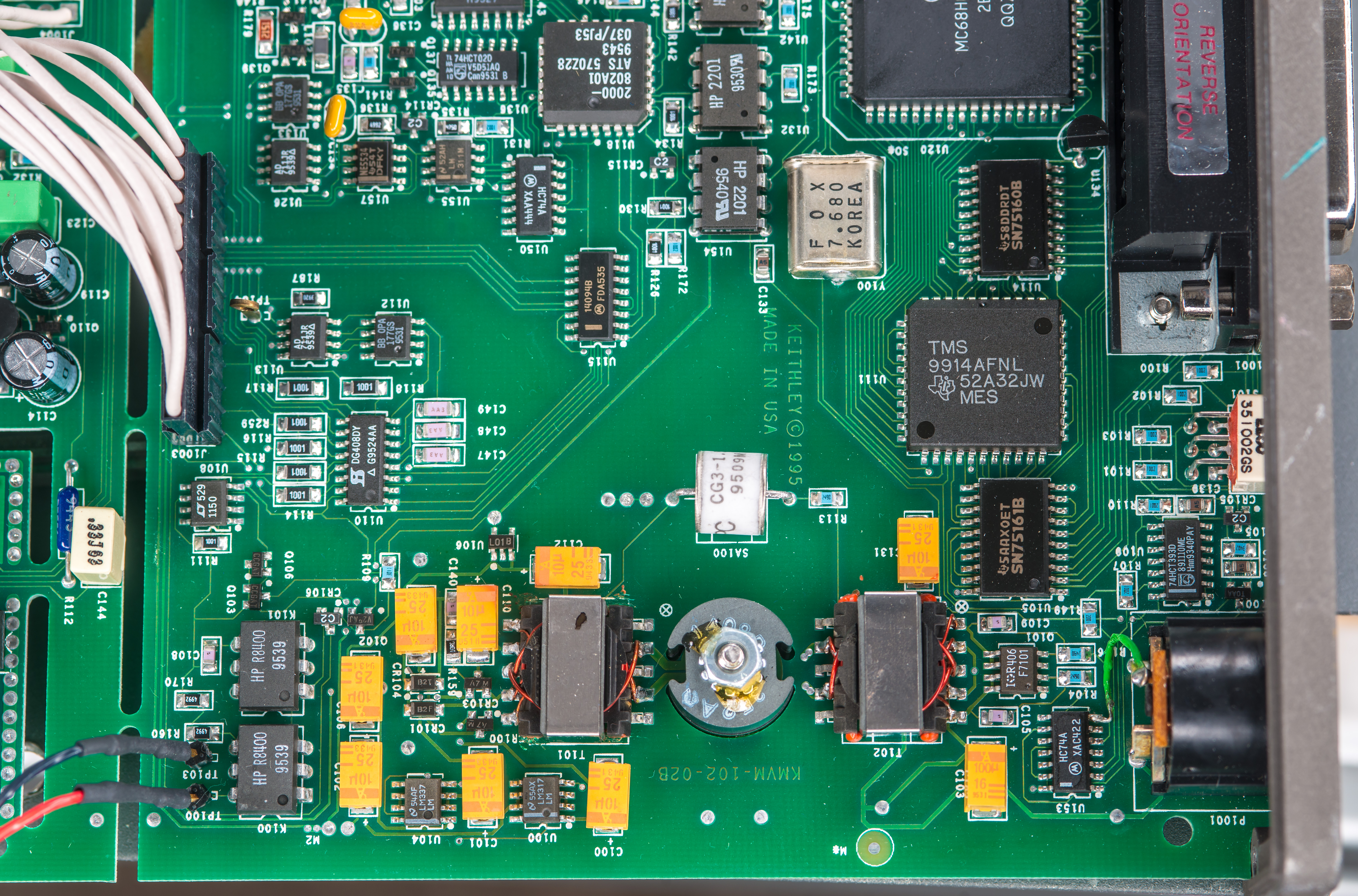
GDT SA100 and series R113 0603 resistor sit between floated front-end section and input earth-referenced ground for additional protection against high voltages. Both input and output sides of power convertor are decoupled and filtered with number of yellow 7343 size tantalum capacitors. All capacitors except C103 are specified at 10 µF 25V rating.
Firmware backup
KM-VM Firmware dump, binary file, checksum 0xF7C46
Any Motorola 6811 guru’s around to figure out what is the communication protocol and features of this instrument?
Power-up and first tests
First attempt was to apply prescribed +5V to the DIN5 input receptacle. For powering this Keithley KM-VM I’ve used trusted Keithley 2425 SMU, configured in 4-wire sense mode for +5.0000 VDC output and 3A current compliance limit. Upon power up initial current draw spiked around +1.5 A slowly dropping towards +1A.
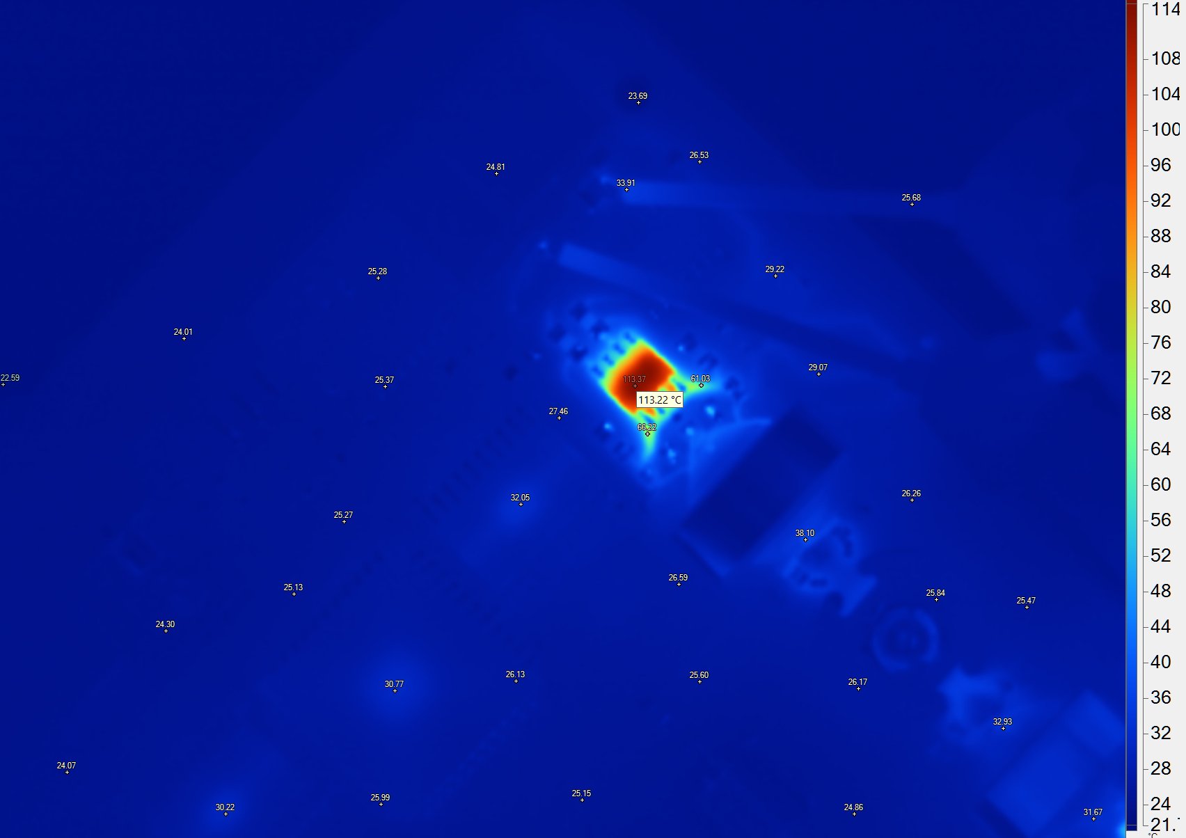
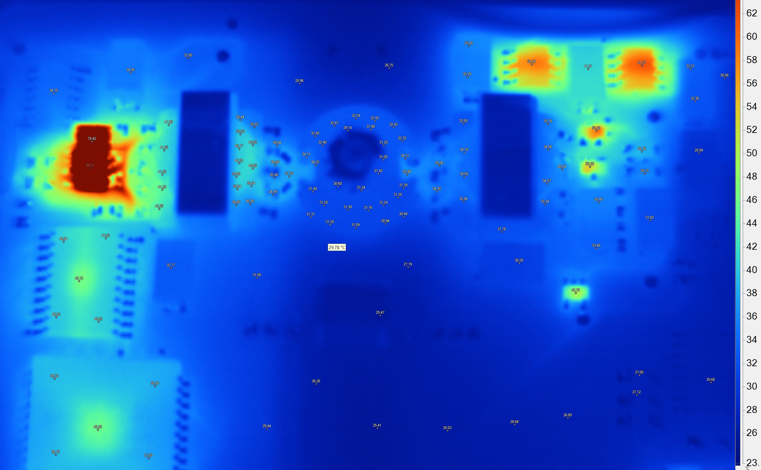
Quick investigation with thermal camera revealed the shining star, sizzling hot FET next to first transformer input. Perhaps this IRF7101 is bad?
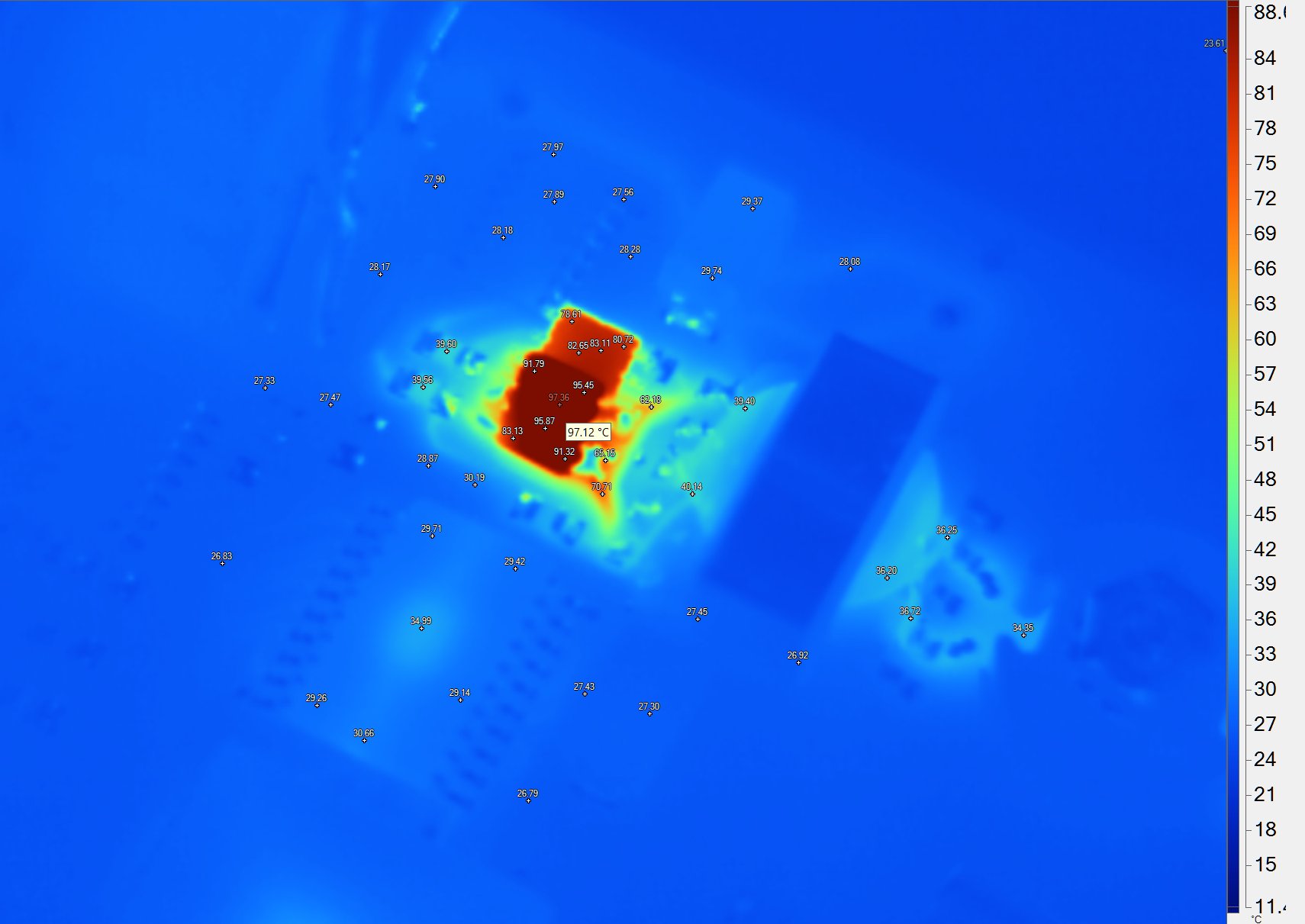
I’ve replaced it with two higher power single NFET, bodged with a tilt to the PCB pads. However new FETs also cooked to high temperatures, but instrument did power up completely. Perhaps I’ll buy something like modern even lower Rdson IRF8313 later on to populate instead of current bodge.
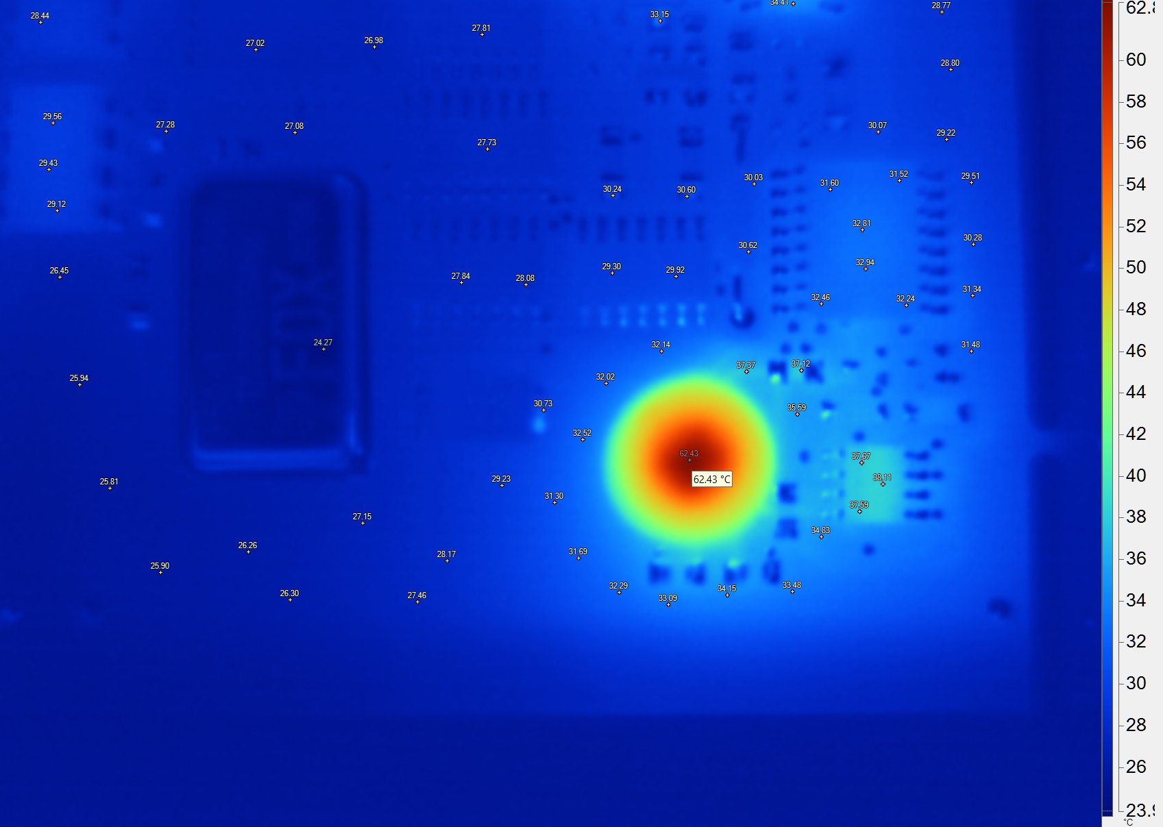
GPIB controller and drivers also was quite warm, while central microprocessor stayed very cool, barely above ambient PCB temperature. Initial suspicion was that digital section have some fault and dead, but checking Y100 crystal life with my Tektronix DPO7104C revealed healthy 7.680 MHz clock and some activity on data lines.

LM399 is also easy to spot by nicely toasty insulation blanket. NE5534 op-amp is another hot spot in the ADC area.
Communication protocol
Regrettably, this instrument lacks support for the modern SCPI (Standard Commands for Programmable Instruments) language over the GPIB (General Purpose Interface Bus) interface. Instead, its communication protocol relies on a less common and more challenging-to-interpret set of letter-style commands. These commands may not adhere to the typical Keithley syntax and structure, so more digging is required. The use of this more obscure communication protocol can be tricky in terms of correct command syntax, command structure, and data interpretation. It may require a deeper understanding of the KM-VM design and circuits to determine what functionality is expected. At least we need to determine commands to trigger and perform acquisition, read data from the instrument and select desired input channel. Would be great to find NPLC setting or triggering parameters command as well, if such is exposed to user.
Interestingly Tektronix website has a manual for somewhat related KM-SM-20V3-5I7-03 Modular Power Supply. This manual is dated also around end of 1995. One of these power supplies is even available for sale on secondary market at the time of this article publication:
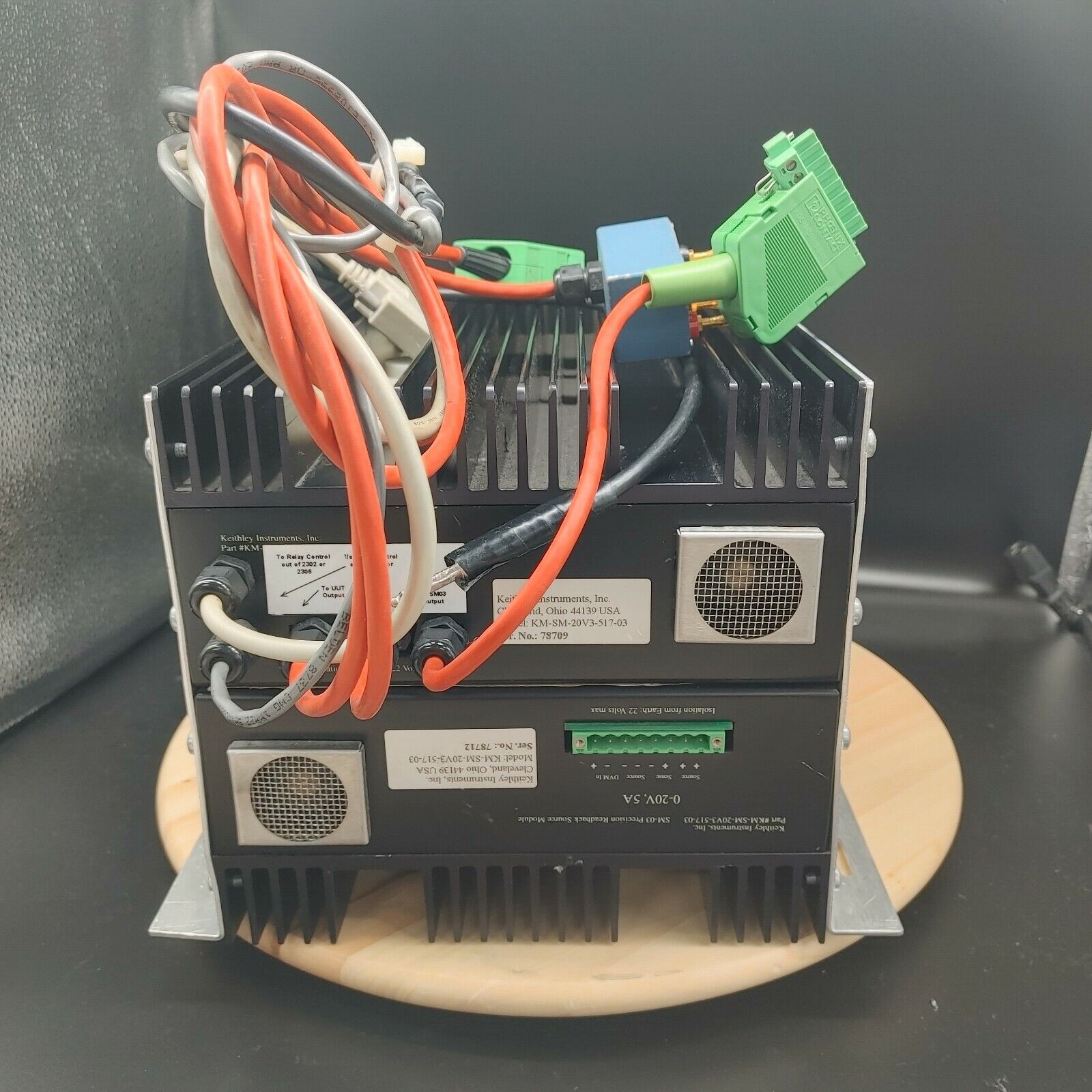
Perhaps these KM-series instruments were attempt of Keithley to produce solutions for integration or for some large customer demands?
Most useful perhaps page 18 of that manual, showcasing command set used by KM-SM, such as listed in table below:
| Command for KM-SM | Function | Returned data |
|---|---|---|
| An | Set current | None |
| A? | Return last programmed current value | Value |
| Vn | Set voltage | None |
| V? | Return last programmed voltage value | Value |
| On | Set output state, 0=Off, 1=On | None |
| O? | Returns output state | Value |
| Pn | Set protection mode | None |
| P? | Return protection state | Value |
| I? | Return 3xx/rev/sernum identification | Example: 300/A1.0/585699 |
| Sn | Set SRQ mask in hex value n | None |
| Mn | Starts measurement, 0 = volts, 2 = milliamps, 3 = DVM input | Measurement value |
| E? | Error status | Hex value |
| Cnv | Calibrate n step, with v value | ? |
Based on these commands idea and after some experimenting with Python and GPIB interface I’ve found some of the working commands:
- M? command query returns 6½-digit measurement result, for example +1.000064
- E? command query returns decimal value, most likely error code
- F*** command doing something, changing range or mode. Measurement value changes
- I? returned A01/serial number string
I got good measurement results using CH1 by applying a +1.0000 VDC signal from the Keithley 2400 SMU, and I was able to obtain meaningful and reliable measurements from this channel with different voltages. However, when attempting to switch for the most interesting CH2 input, I got no much progress with commands guessing as the measurements obtained were not sensible or aligned with expected 1mV or 10mV signal applied. I managed to get CH2 LED to turn on RED few times, but readings were not correct.
Despite troubleshooting and various attempts, I was unable yet to derive plausible data or meaningful results from CH2. It suggests that there might be an issue or fault with the internal circuitry specific to CH2, requiring further investigation and analysis to pinpoint the cause and rectify the situation. Perhaps it was a reason why this box ended up on secondary market after all.
Performance results
TBD?
Summary and conclusion
Interesting thing, thank you, Steve! Hopefully we can make it function unit and get interesting experience with it.
Discussion about this article and related stuff is very welcome in comment section or at our own IRC-chat server: irc.xdevs.com (standard port 6667, channel: #xDevs.com) or via email contact.
Projects like this are born from passion and a desire to share how things work. Education is the foundation of a healthy society - especially important in today's volatile world. xDevs began as a personal project notepad in Kherson, Ukraine back in 2008 and has grown with support of passionate readers just like you. There are no (and never will be) any ads, sponsors or shareholders behind xDevs.com, just a commitment to inspire and help learning. If you are in a position to help others like us, please consider supporting xDevs.com’s home-country Ukraine in its defense of freedom to speak, freedom to live in peace and freedom to choose their way. You can use official site to support Ukraine – United24 or Help99. Every cent counts.
Modified: Dec. 14, 2023, 5:57 a.m.