Contents
DRAFT
- Intro
- Disclaimer
- Manual references
- Model 2182 Initial inspection and basic disassembly
- Model 2182 Repair workflow
- Model 2182A teardown and analysis
- Model 2182A Repair workflow
- Tweaks and tricks
- Calibration
- Performance verification
- Restoration summary
Intro
Following good local tradition, we are back to Keithley instruments this time. Some might already read Keithley 182 nanovoltmeter review. In this article modern replacement for that voltmeter will be studied and repaired. Welcome original Model 2182 and very similar newer 2182A nanovoltmeters.
These were developed back in year 2000 to compete with 7½-digit HP’s 34420A µOhm/nV-meter. Tektronix (Keithley merged with Tek from 2010) still produces and sell 2182A starting at (USD $3410, 2017 price) or 9550 CAD in summer 2026. This instrument is not a common tool on most labs, due to it’s specialty and use specifics.
Older meter was functioning normally, except for the channel 2 readout. Newer 2182A was acquired completely dead, with literally blown input section due to exposure to high energy signal. In article we will go over legacy 2182 first, and then highlight the repair and differences of the updated Model 2182A later.
| Function | Ranges | Accuracy |
|---|---|---|
| DC Voltage CH1 | ±10mV, ±100mV, ±1V, ±10V, ±100V | Best 1 Year Specification: ±25 ppm + 2 |
| DC Voltage CH2 | ±100mV, ±1V, ±10V | Best 1 Year Specification: ±25 ppm + 2 |
| DC Noise spec | 6 nV & 25s NPLC5, FILT, 10mV, 2.5µV & 1s NPLC1, FILT, 10V | |
| Temperature | -200°C to +1820°C, Type J,K,N,T,E,R,S,B | Accuracy: ±0.2 °C, 0.001°C resolution |
| ADC linearity | ±0.8ppm of reading + 0.5ppm of range | |
| Input impedance | >10 GΩ for 10mV-10V ranges |
Table 1: Model 2182A key specifications
As far as we know, there are no additional options available to upgrade Keithley 2182/2182A.
Disclaimer
Redistribution and use of this article or any images or files referenced in it, in source and binary forms, with or without modification, are permitted provided that the following conditions are met:
- Redistribution of article must retain the above copyright notice, this list of conditions, link to this page (/fix/kei2182/) and the following disclaimer.
- Redistribution of files in binary form must reproduce the above copyright notice, this list of conditions, link to this page (/fix/kei2182/), and the following disclaimer in the documentation and/or other materials provided with the distribution, for example Read-me file.
All information posted here is hosted just for education purposes and provided AS IS. In no event shall the author, xDevs.com site, or any other 3rd party, including Keithley or Tektronix be liable for any special, direct, indirect, or consequential damages or any damages whatsoever resulting from loss of use, data or profits, whether in an action of contract, negligence or other tortuous action, arising out of or in connection with the use or performance of information published here.
If you willing to contribute or add your experience regarding HP/Agilent/Keysight instruments repairs or provide extra information, you can do so following these simple instructions
As usual, all photos are clickable for high-resolution version.
Manual references
Model 2182 Nanovoltmeter User’s Manual, Rev.D April 2002
Model 2182 Nanovoltmeter Service Manual, Rev.C September 2001
Model 2182 Quick Reference Guide (Japanese)
Model 2182 Specifications, Rev.D July 2001
Model 2182A Nanovoltmeter datasheet
Model 2182A Nanovoltmeter datasheet
Model 2182/2182A Nanovoltmeter User’s Manual, Rev.A June 2004
Model 2182/2182A Quick Reference Guide, Rev.A June 2004
Model 2182A Specifications, Rev.D October 2013
Model 2188 : Low thermal calibration shorting plug for 2182
Unfortunately, there is no schematics available in public service manuals for Model 2182.
Model 2182 Initial inspection and basic disassembly
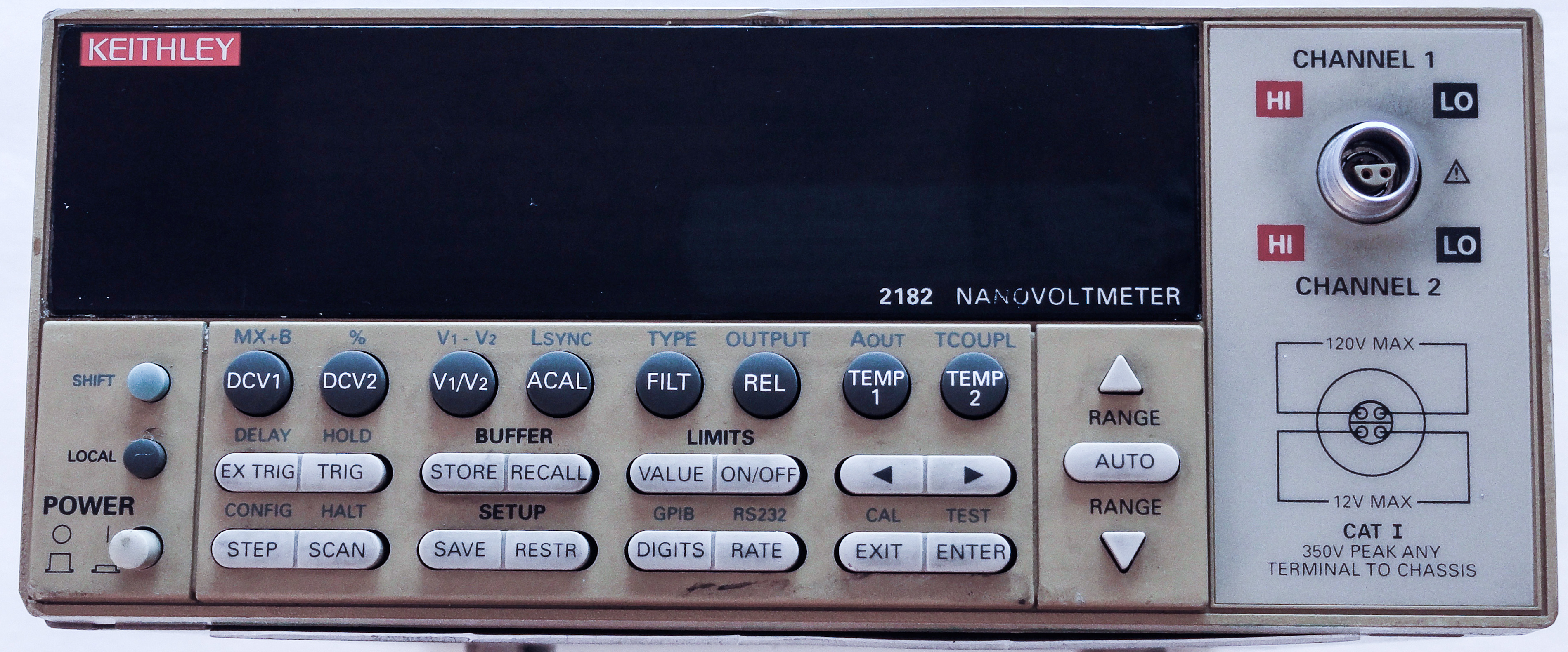
Image 1: Keithley Model 2182 nV-meter front
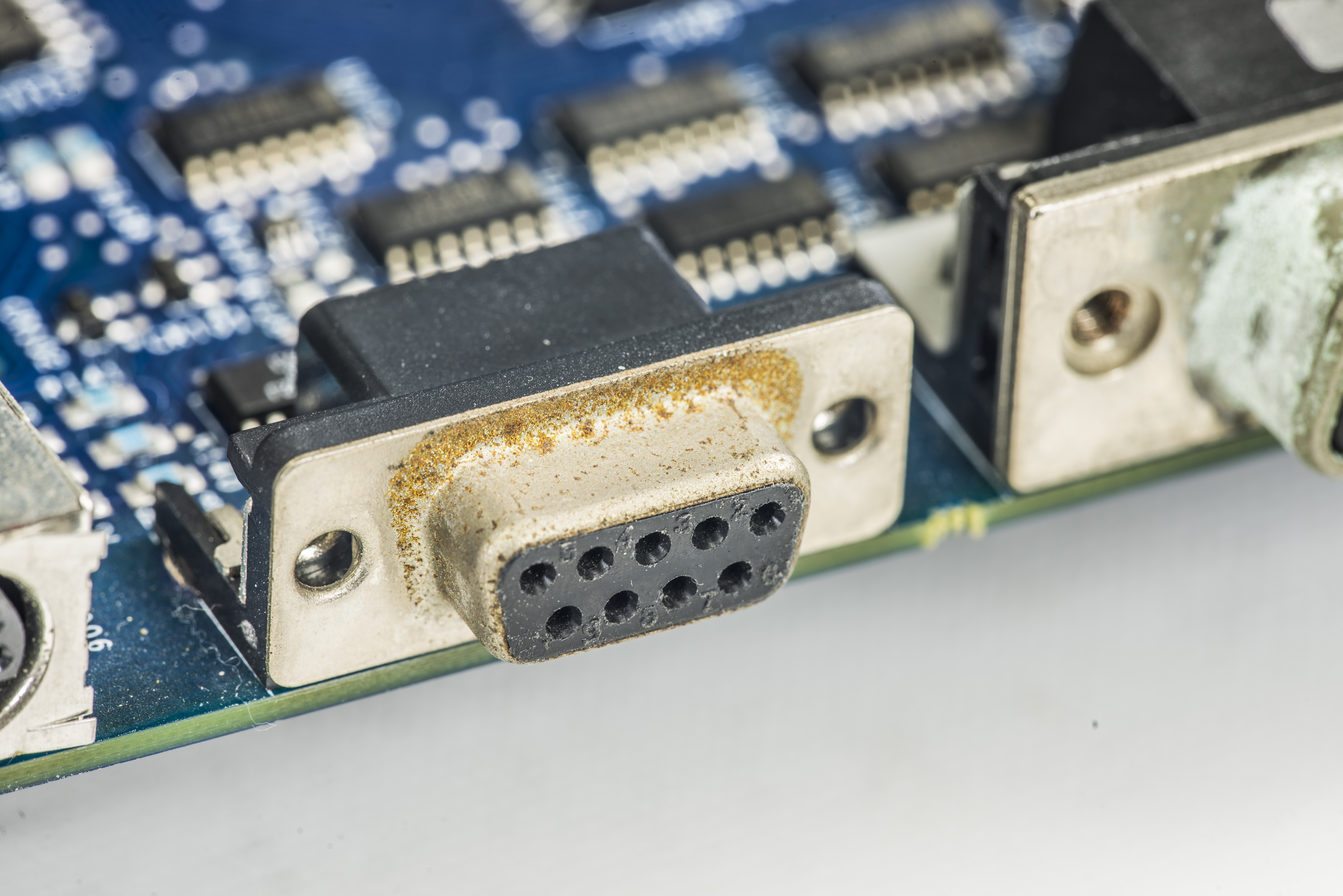
2182 is same footprint and size as other Keithley’s meters, such as 2001, 2002, 2400 series SMU, etc. Input connector is specialized type, LEMO V series, custom version of FVN.0V.304 (cable part) / EVN.0V.304, very same as one used in HPAK 34420A. It’s compatible with Keysight’s 34102A Low Thermal Input Cable.
For calibration purposes original Keithley 2188 shorting plug or compatible Keysight 34103A shorting plug can be used.
If you need to make custom cables, you can get original Keithley “2182-KIT connector” or compatible Keysight 34104A input connector for USD $121. Based on EEVBlog discussion LEMO’s part number for connector is FVN.1S.304.CLYC37Z, referncing LEMO catalog. It’s not cheap, Digikey retailer sells these connectors for USD $109.2
After few screws removal, cover is easily removed, just like most of other half-rack Keithley devices.
Let’s take a look inside:
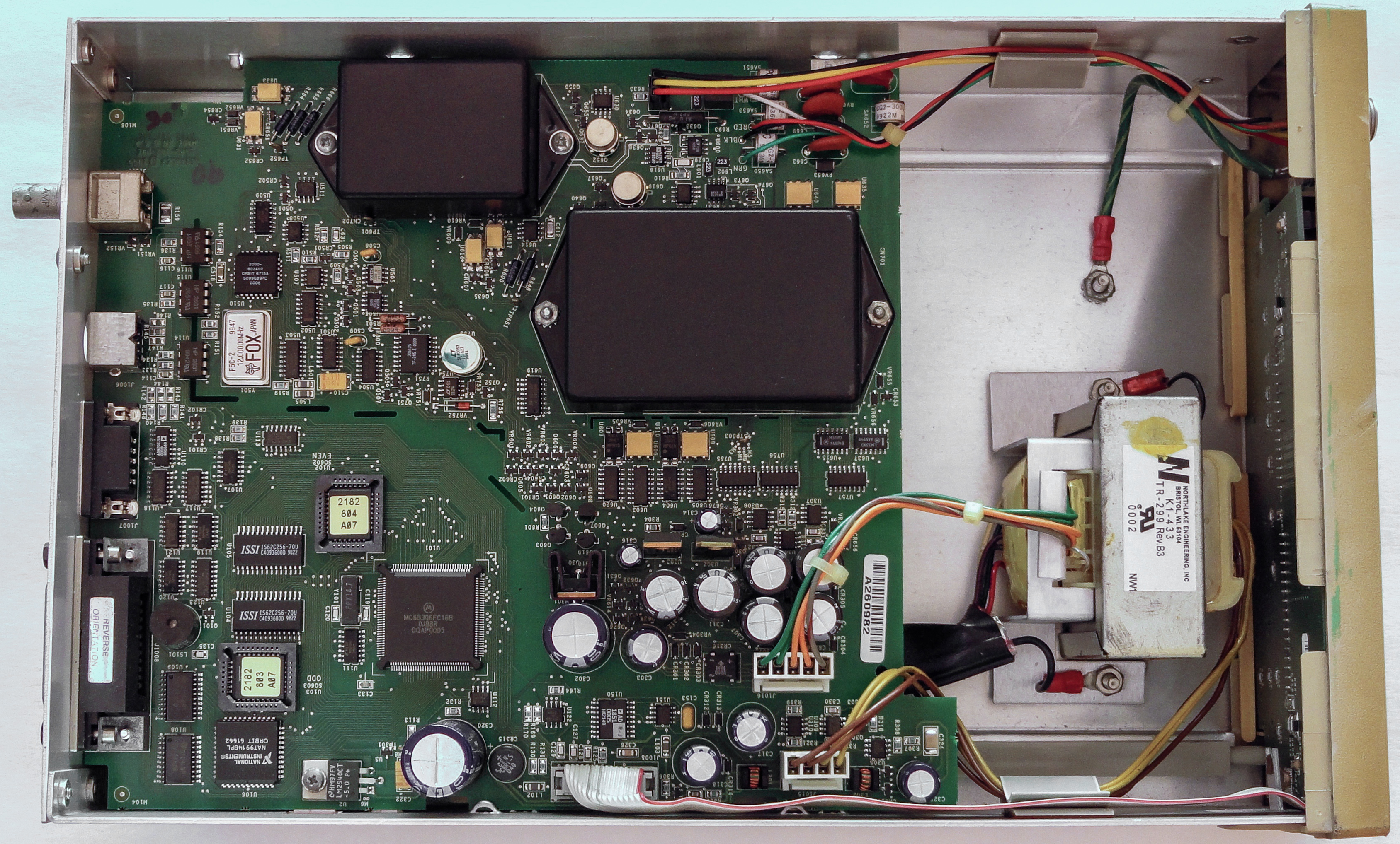
Overall construction is similar to 6½-digit DMM Model 2000, but with very different mainboard front end. One big mainboard with all components located on middle of chassis, and mains transformer mounted on front side of the instruments. Bit surprised to see just regular wiring from input LEMO connector to PCB. Expected low-noise shielded cable instead.
Animated photograph of both 2000 and 2182 boards illustrates very small difference in digital domain of both meters. No surprises, engineers usually reuse existing design blocks. This approach works fine for digital due to firmware flexibility, but analog sections are completely different. One notable difference is presence of Analog Devices AD1851, which is 16-bit ±3V PCM Audio DAC. This DAC is used for ±1.2V analog output, which takes measured signal from digital domain and provides analog output with programmable gain from 10-9 to 106. This feature is similar to analog output of Keithley 182 and can be useful for datalogging with external devices, if ±0.1% accuracy is sufficient.
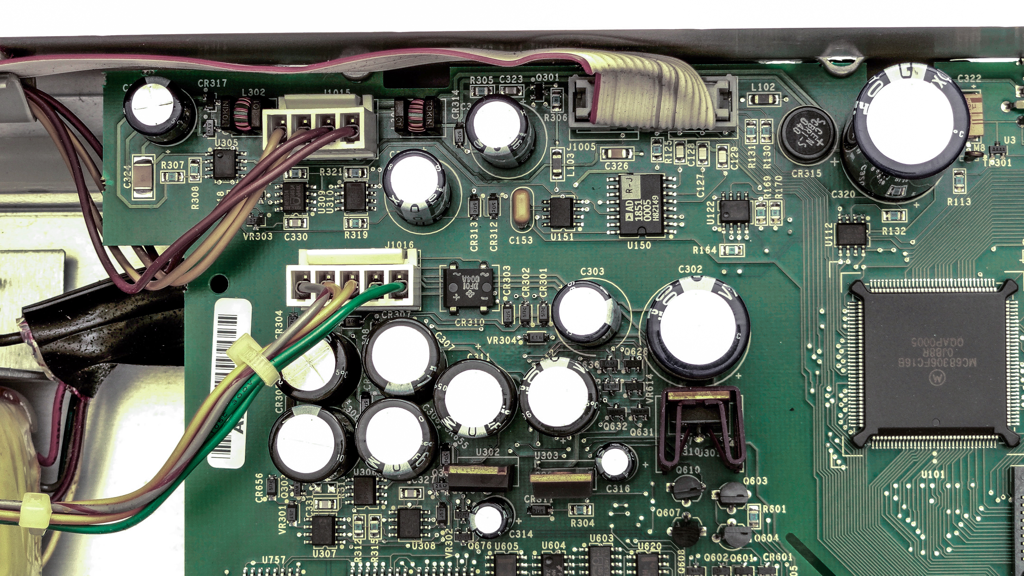

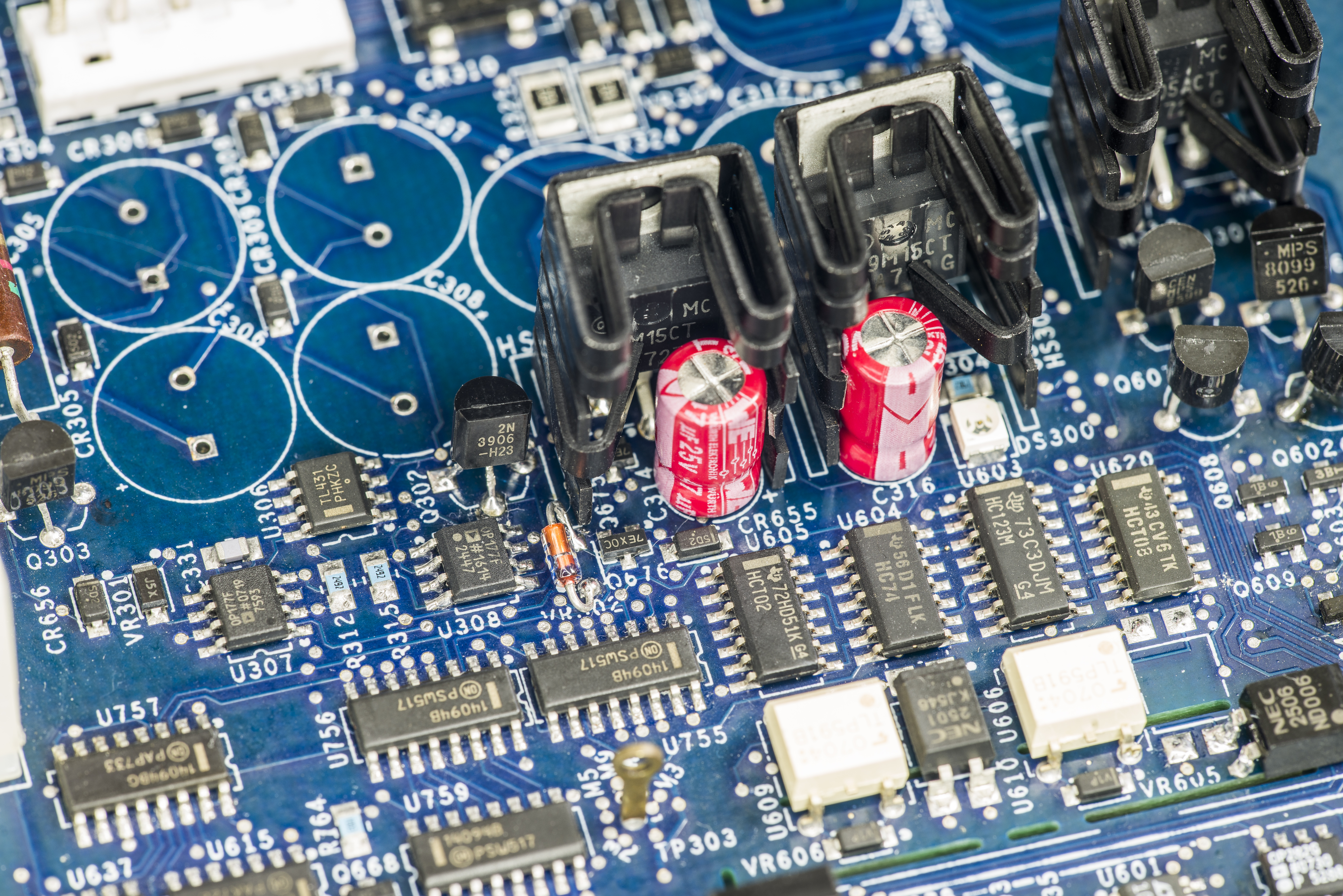
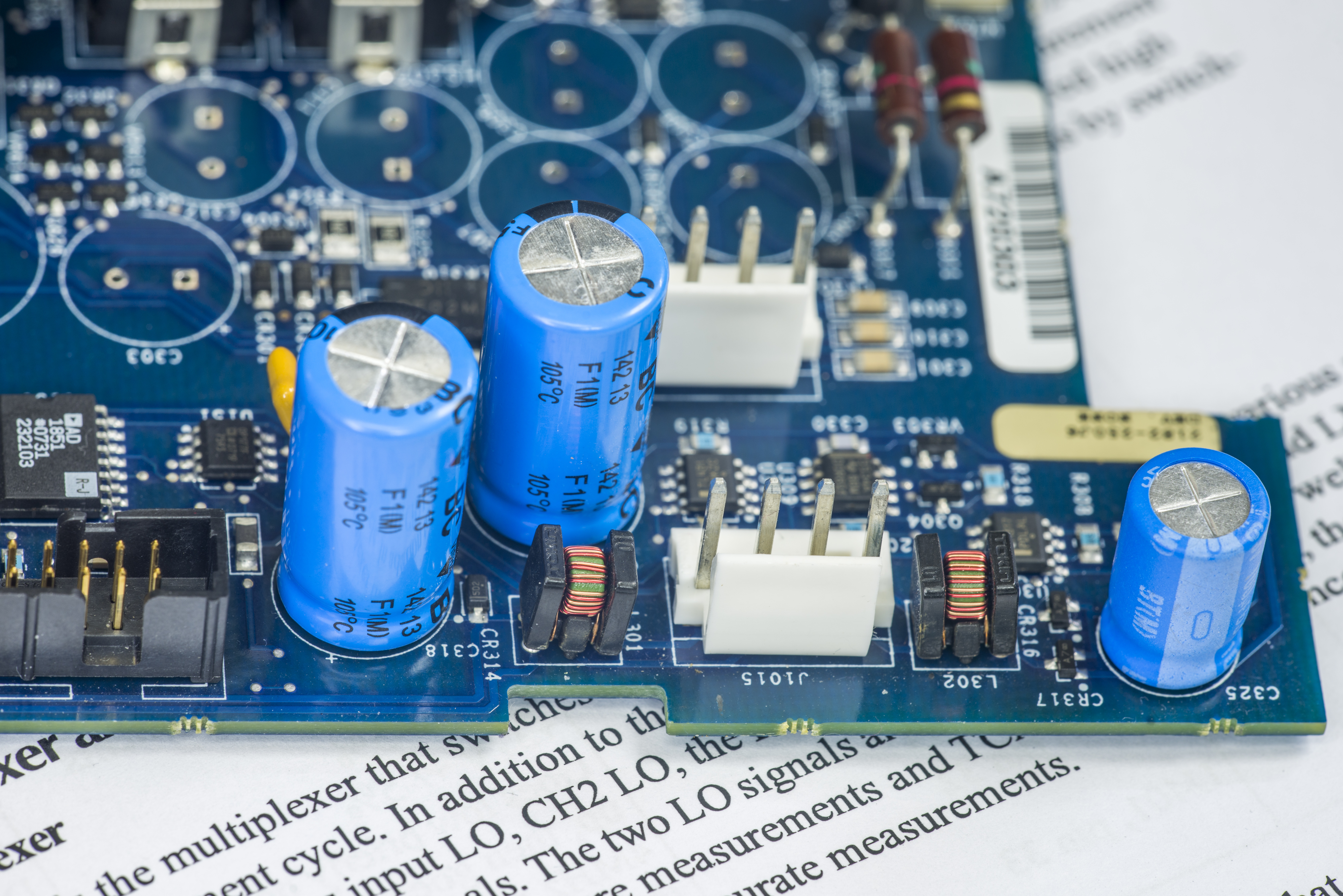
Onboard power supply is separated into independent digital and analog sections, coming from separate transformer sections. Digital supply, powering main processor, front panel and communications interface is routed thru J1015 connector. As visible on photos, set of capacitors around PSU inputs already went bad (no wonder, 16 years already for this instrument) and urge for replacement and PCB cleanup.
Analog power provided from J1016 connector, rectified by CR310 bridge and regulated by U302 (+15VDC, 78M15), U303 (-15VDC, 79M15) and U301 (+5VDC, 7805) into main analog supplies. Few more regulators such as U304 (LM295T), U305 (LM317M) and references (U306,U310, TL431CD) provide local auxiliary voltages near by.
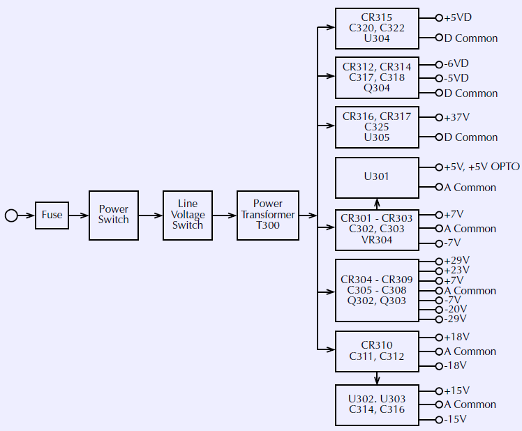
Initial checks are always starting from power supply, and service manual lists nice step-by-step procedure:
| Step | Item/component | Required condition | Remarks |
|---|---|---|---|
| 1 | Line fuse | Check continuity | Remove to check |
| 2 | Line voltage | 120V/240V as required | Check power module position |
| 3 | Line power | Plugged into live receptacle, power on | Check for correct power-up sequence |
| 4 | U304, pin 2 | +5V ±5% | +5VD, referenced to TP301 |
| 5 | U305, pin 2 | +37V ±5% | +37V, referenced to TP301 |
| 6 | CR313 anode | -6V ±20% | -6VD, referenced to TP301 |
| 7 | Q304, pin 2 | -5V, ±5% | -5VD, referenced to TP301 |
| 8 | U302, pin 3 | +15V ±5% | +15V, referenced to TP303 |
| 9 | U303, pin 3 | -15V ±5% | -15V, referenced to TP303 |
| 10 | U301, pin 3 | +5V ±5% | +5V, referenced to TP303 |
| 11 | CR305 cathode | +29V ±20% | +29V, referenced to TP303 |
| 12 | CR309 anode | -29V ±20% | -29V, referenced to TP303 |
| 13 | CR310 V+, pin 1 | +18V ±20% | +18V, referenced to TP303 |
| 14 | CR310 V-, pin 2 | -18V ±20% | -18V, referenced to TP303 |
| 15 | CR306 anode | -7V ±20% | -7V, reference to TP303 |
| 16 | CR308 cathode | +7V ±5% | +7V, referenced to TP303 |
Table 2: Model 2182 power supply check points
Digital construction is shown on block diagram from service manual:
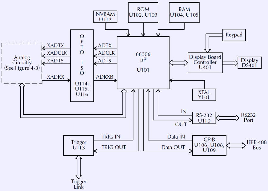
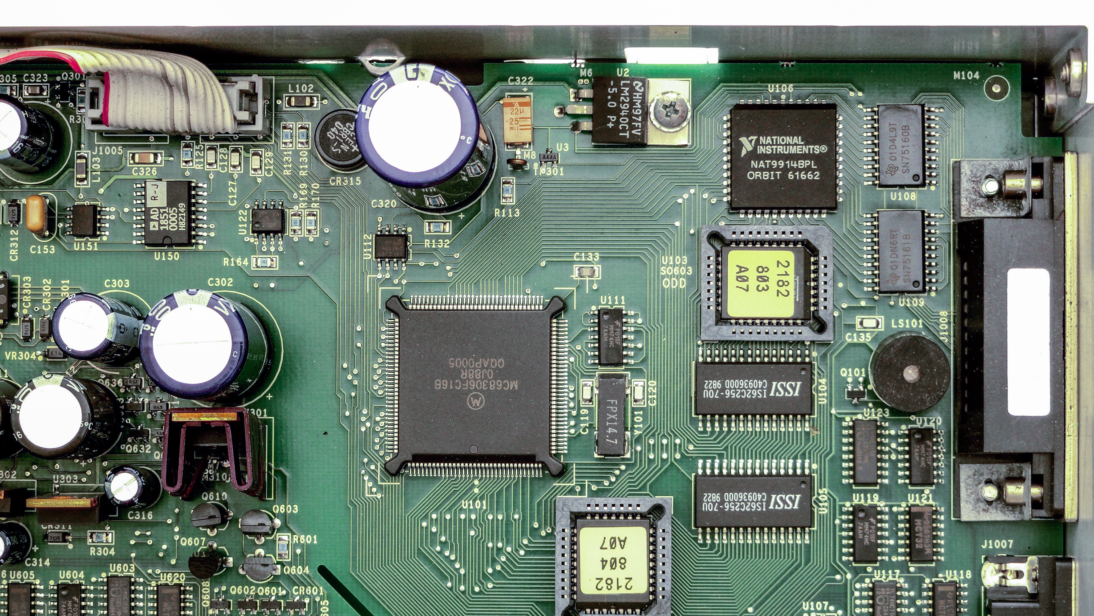
Socketed ROM ICs U102 and U103 contain firmware code, which we downloaded and provided in firmware section below. U103 stores the D0-D7 bits of each data word, and U103 stores the D8-D15 bits. Calibration constants and settings are stored in I2C EEPROM U112 (24LC16B). Everything else is fairly usual, RS232 with level converter and GPIB interface based on National Instruments NAT9914BPL chipset. There is a speaker on board, so instrument can emit sounds when error or alarms occur.
Analog circuitry and front-end design
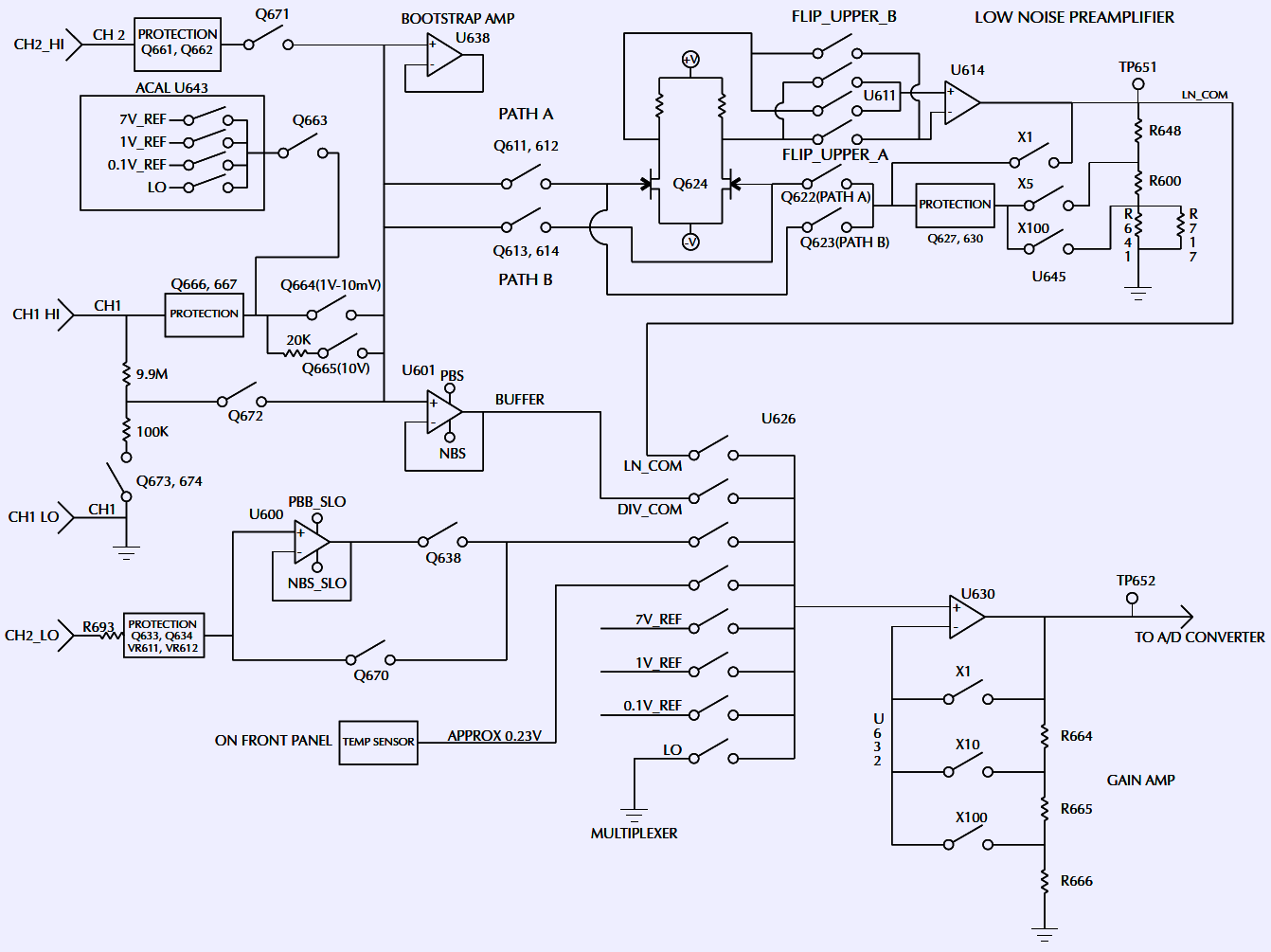
Service manual again helpful with structural diagram of all analog sections and blocks.
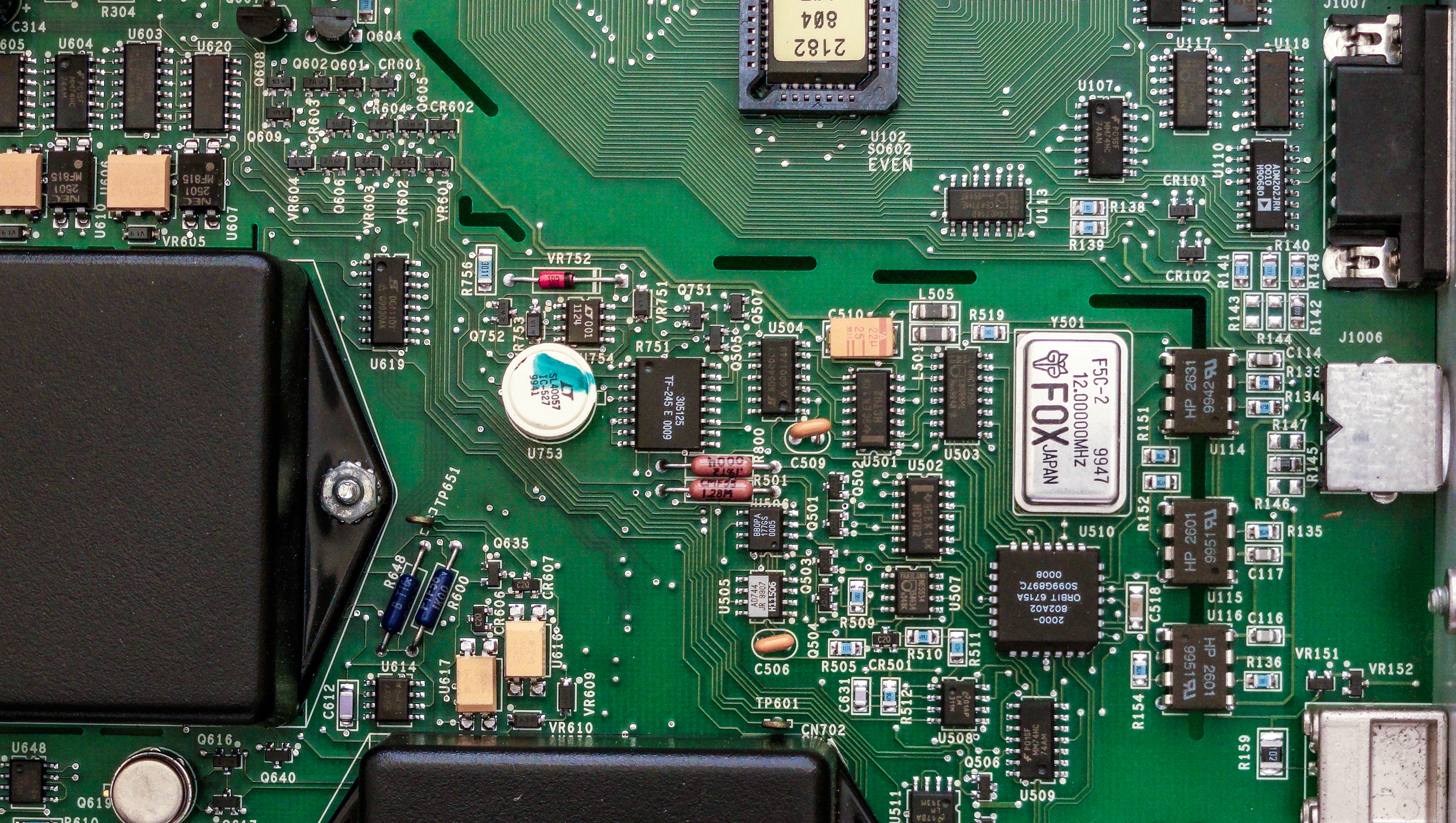
Good old pre-selected 0.5ppm/°C Linear LM399 voltage reference provide ACAL functionality for nanovoltmeter front-end, while regular 6.4V zener provide reference level for the ADC. This is bit different than regular 6½-digit multimeters on the market, like Keithley 2000, where same LM399 used for all reference levels.
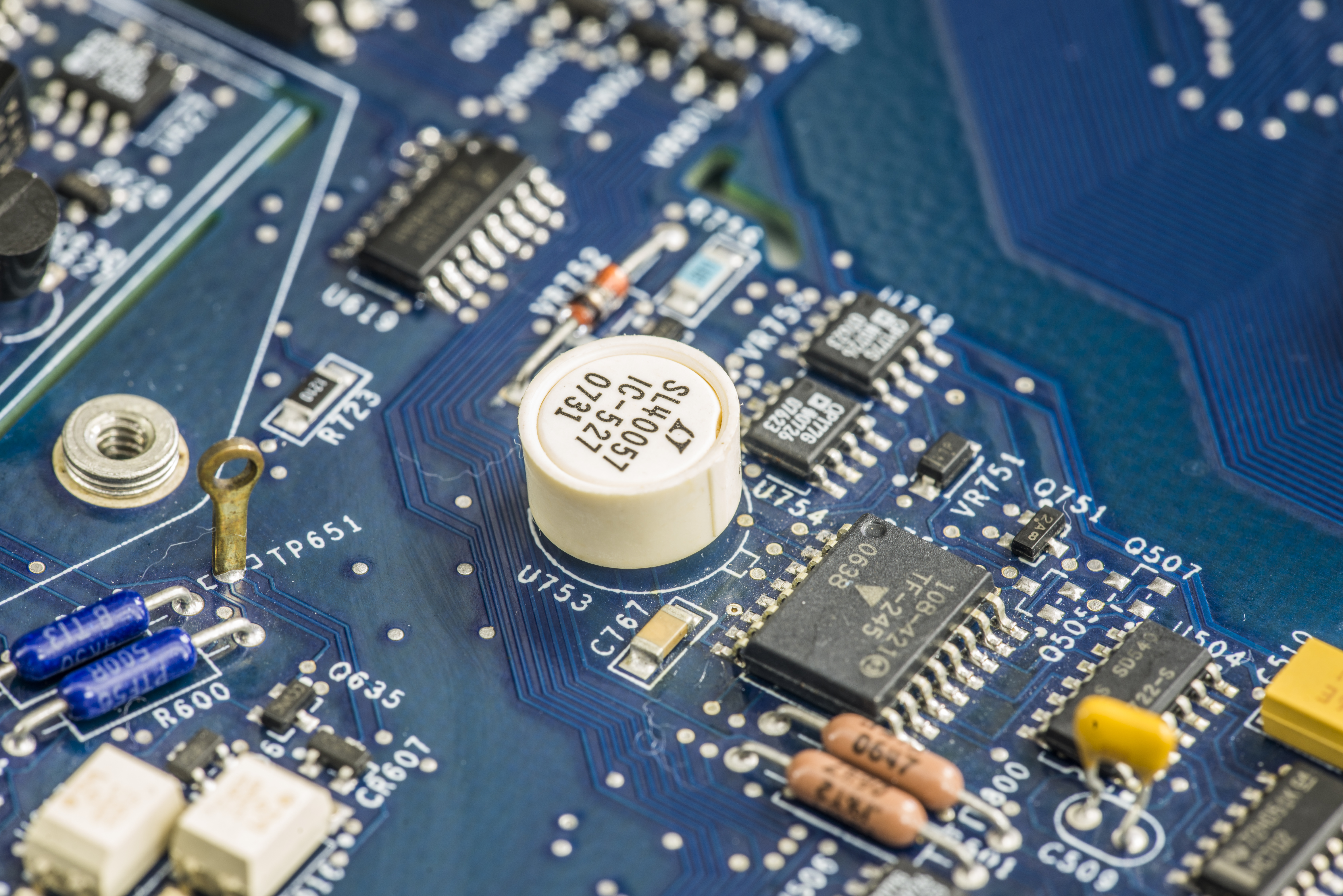
R751 custom TF-245 resistor network located just near. This resistor network was known point of failure in other Keithley’s instruments, such as Model 2000 and Model 2400 SMU, so it will be among first to check during repair.
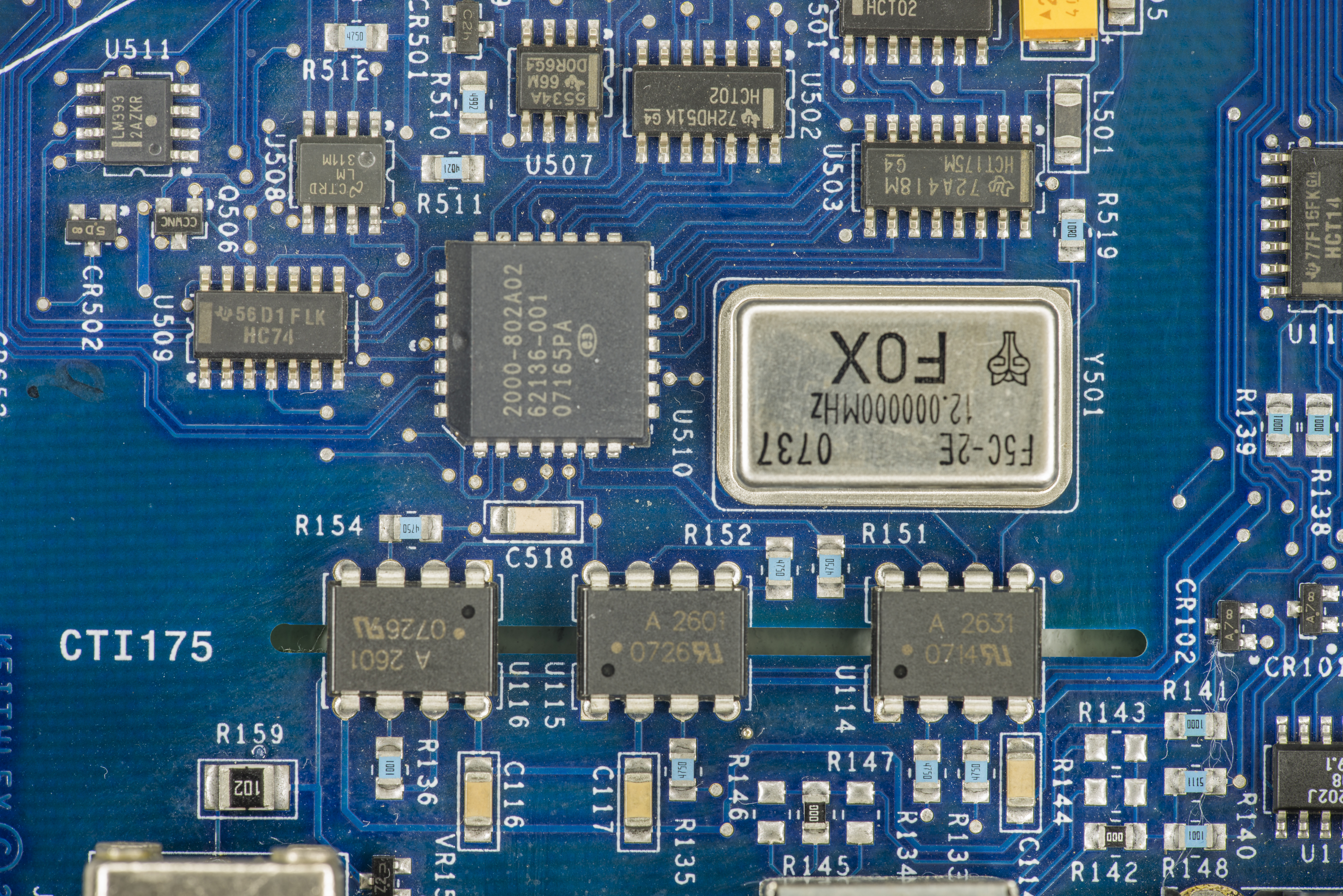
This 2182, manufactured in year 2000, already using custom logic array for integrating ADC control (U510), marked 2000-802A02 ORBIT. This chip is used on many Keithley instruments and is equivalent of ALTERA MAX EPM7160 CPLD logic (2000-802A01). Interface to digital board is isolated thru optocouplers U114 (HCPL-2531), U115,U116 (HCPL-2601).
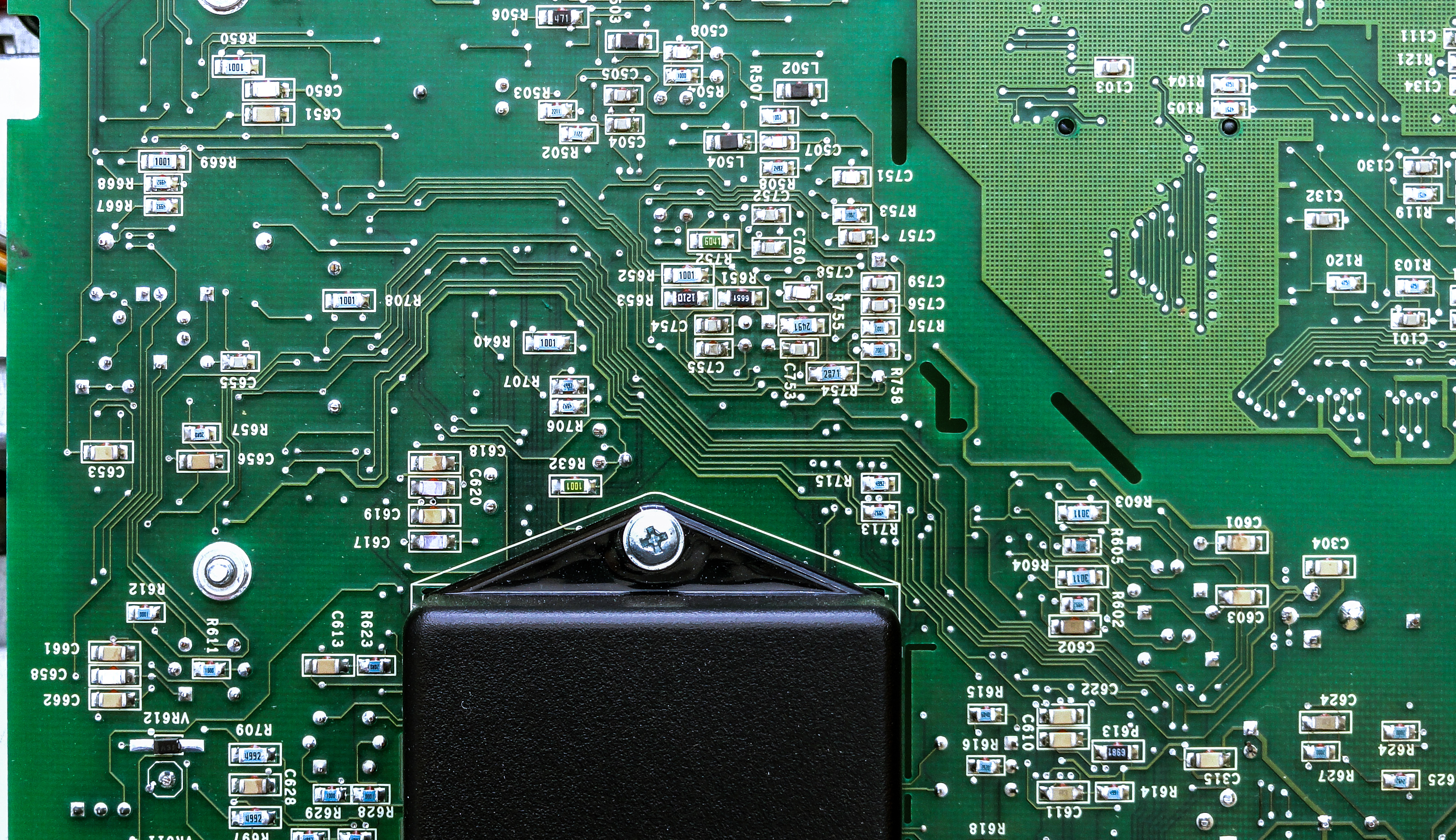
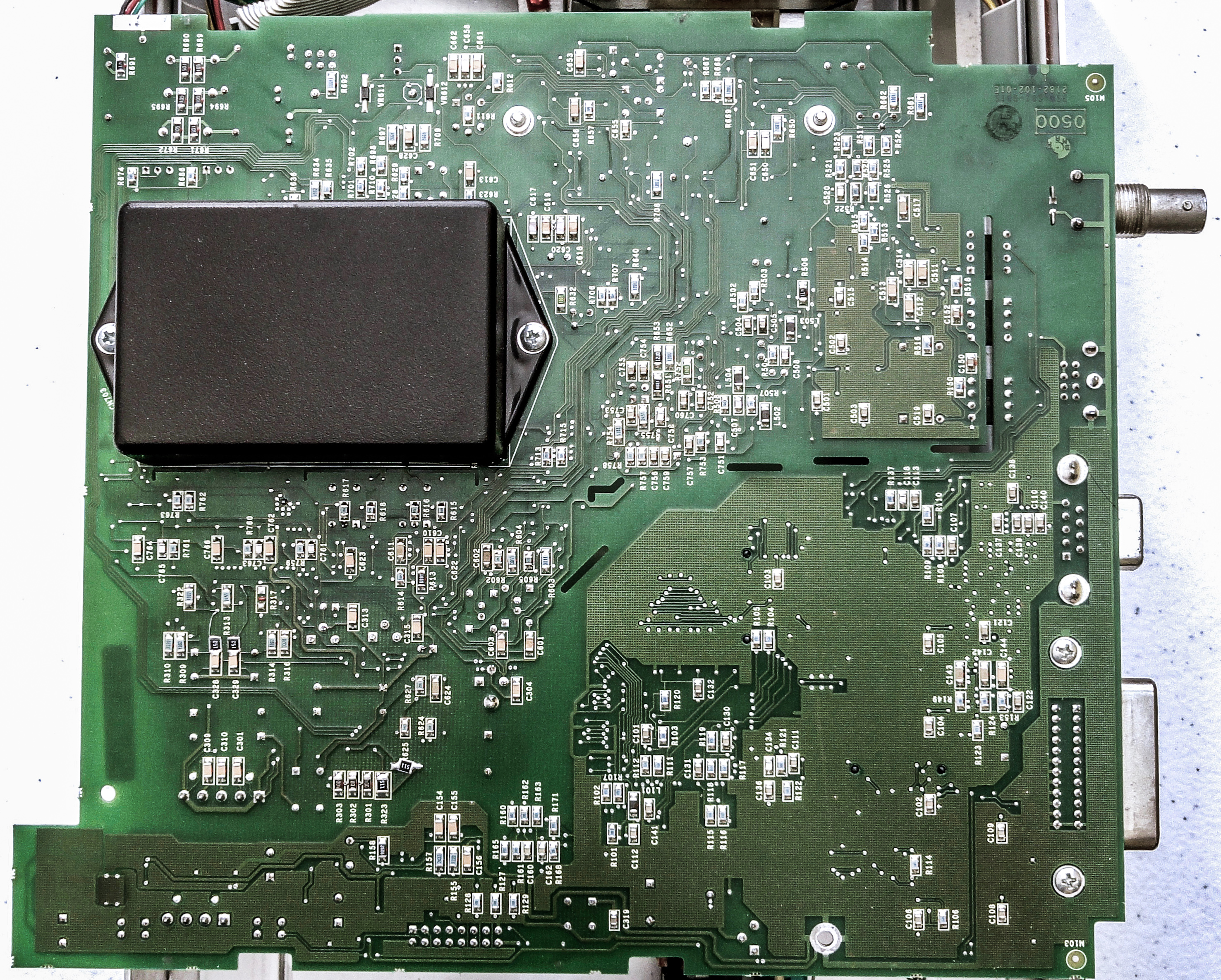
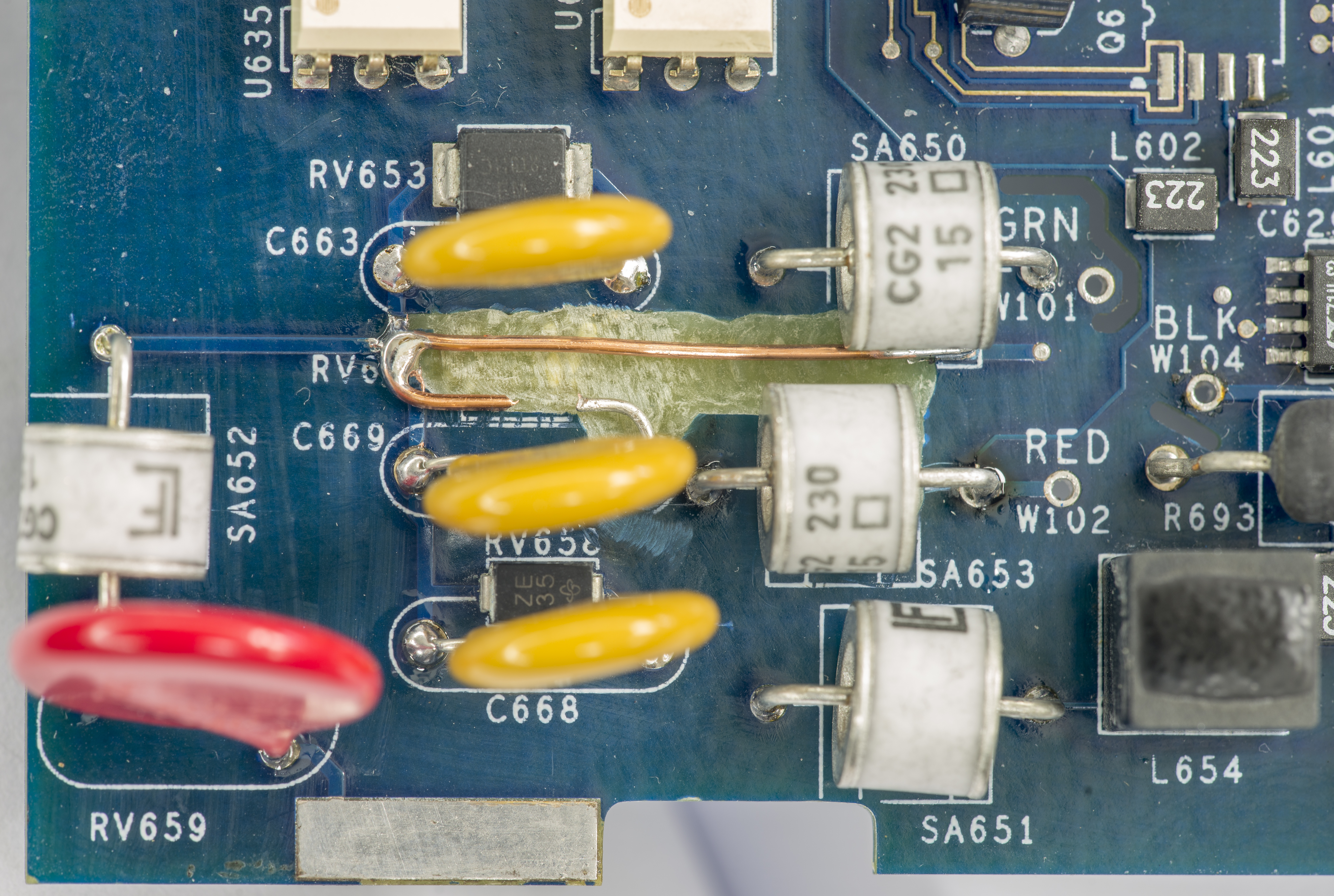
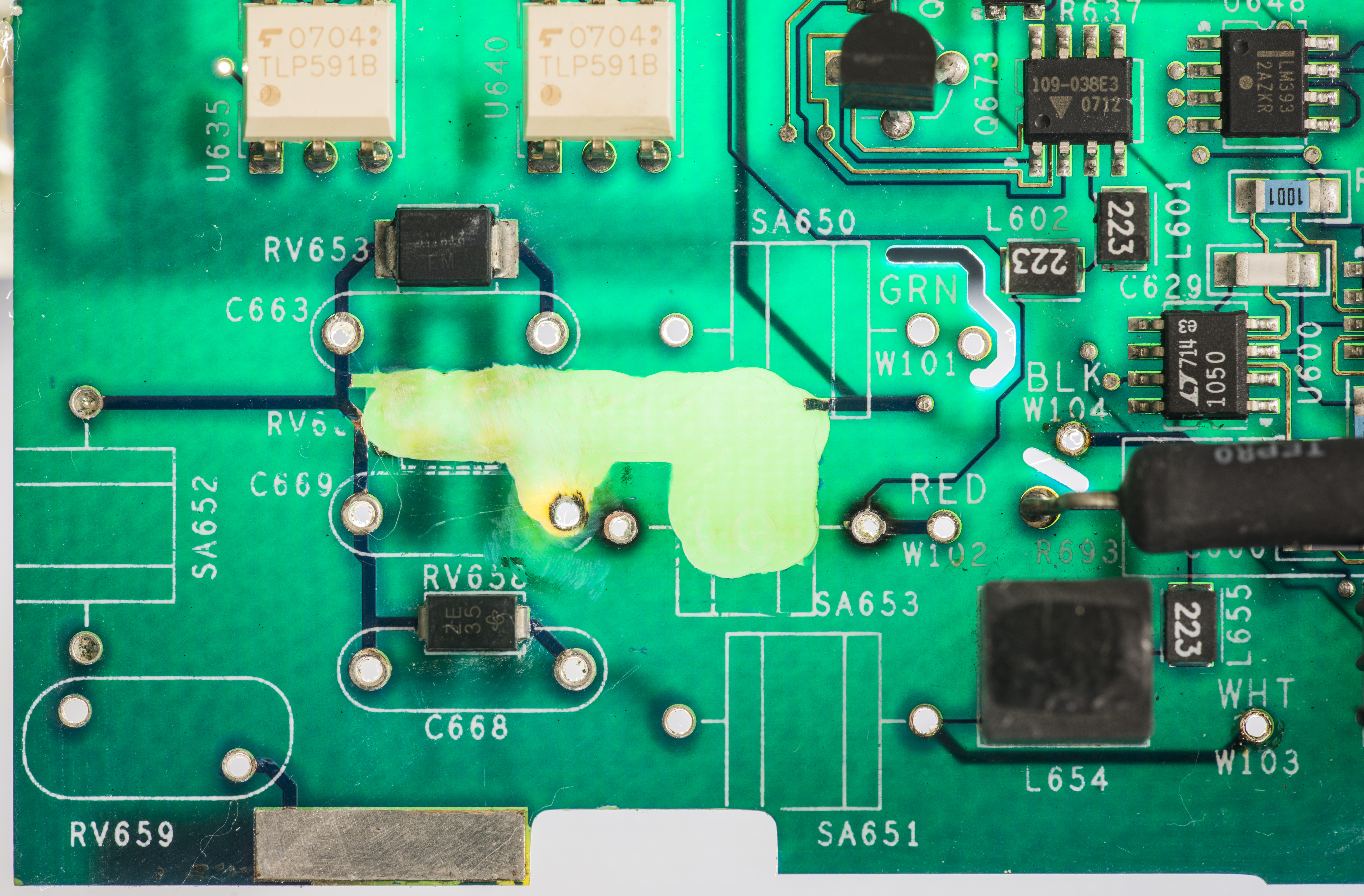
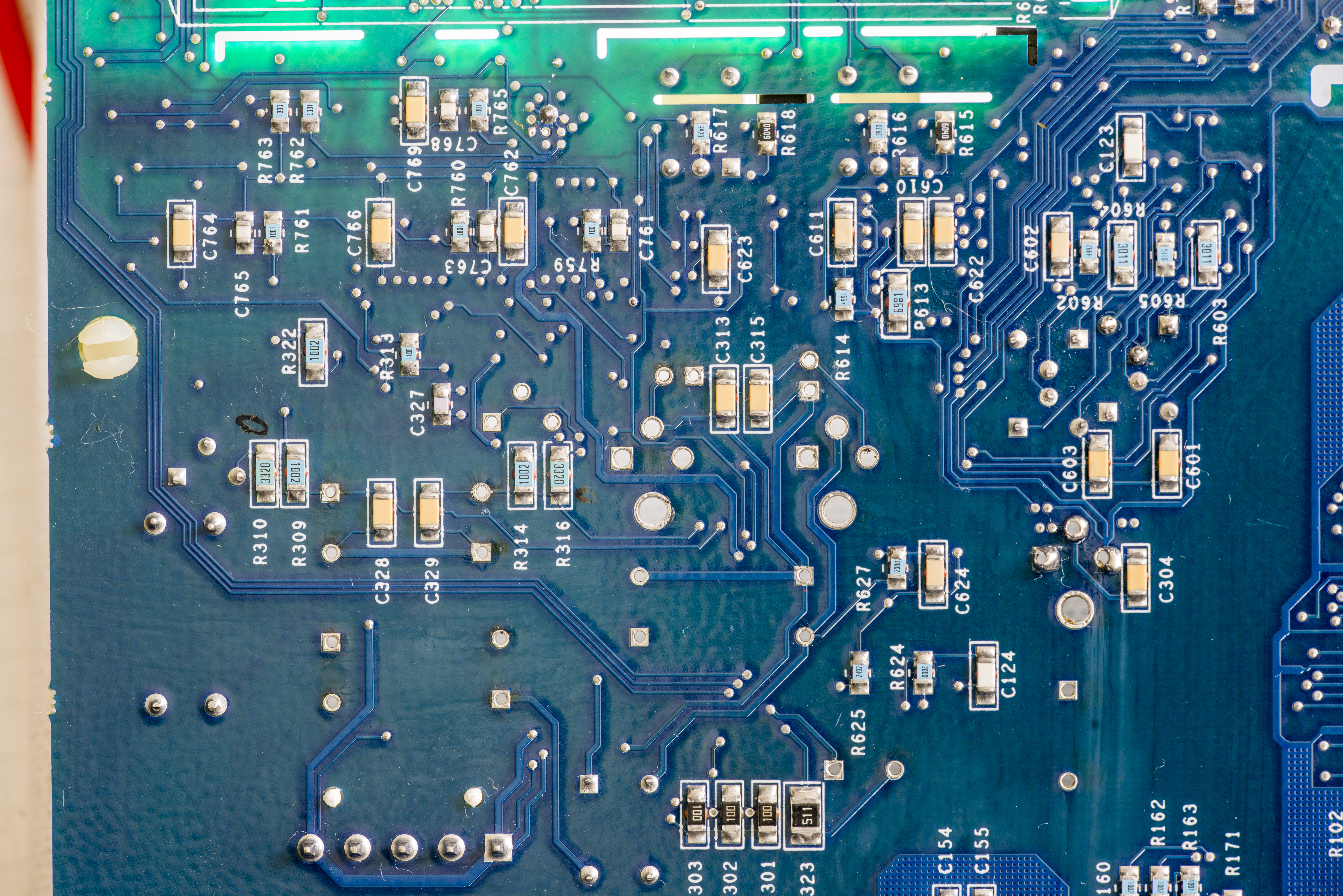
There are only passive components located on bottom side of the board. PCB is four layer, with extensive use of guard rings in sensitive areas. Routing is a bit spaghetti-like, so it’s not that easy to trace signal path. I’ve learn this hard way during Model 2001 repairs.
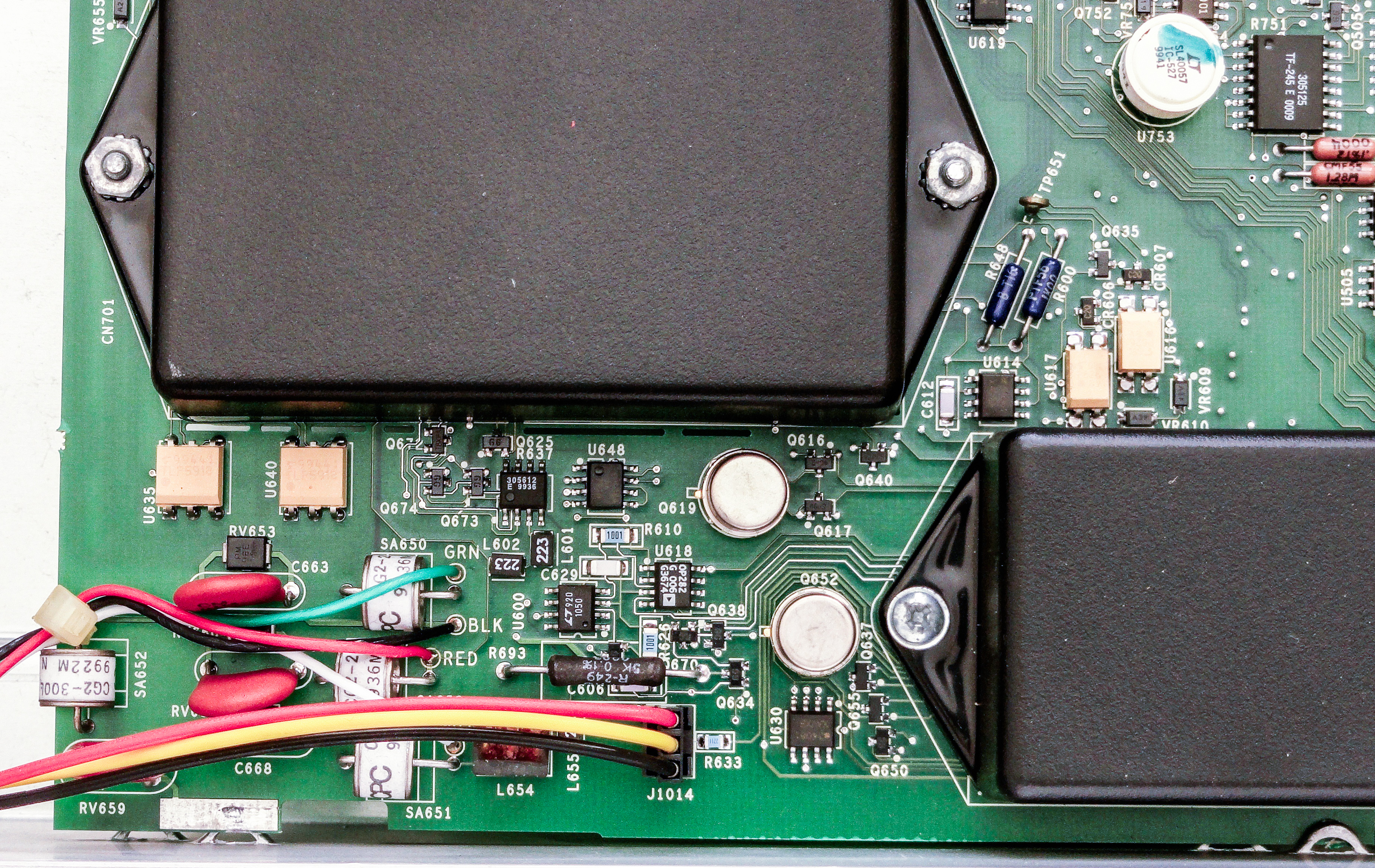
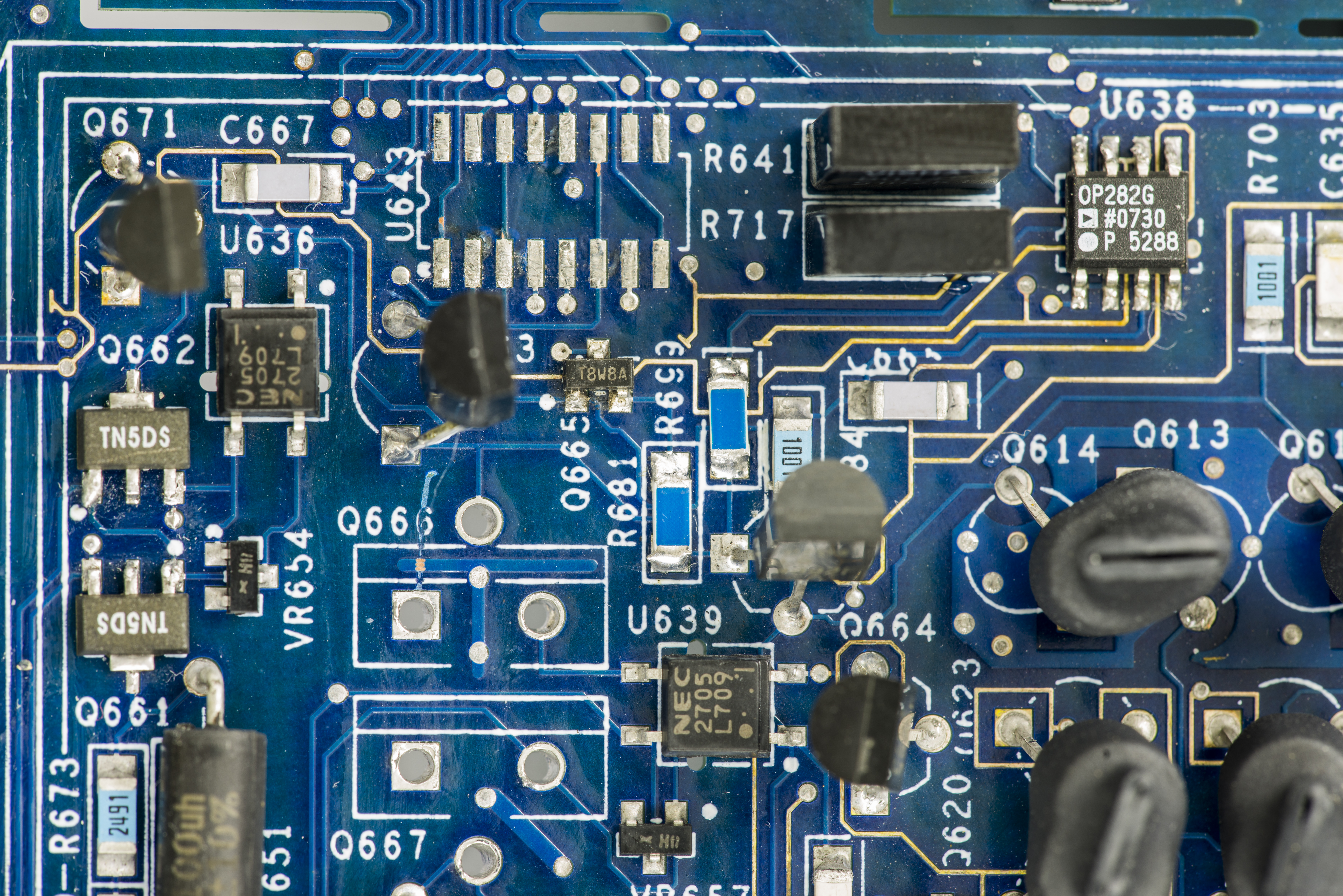
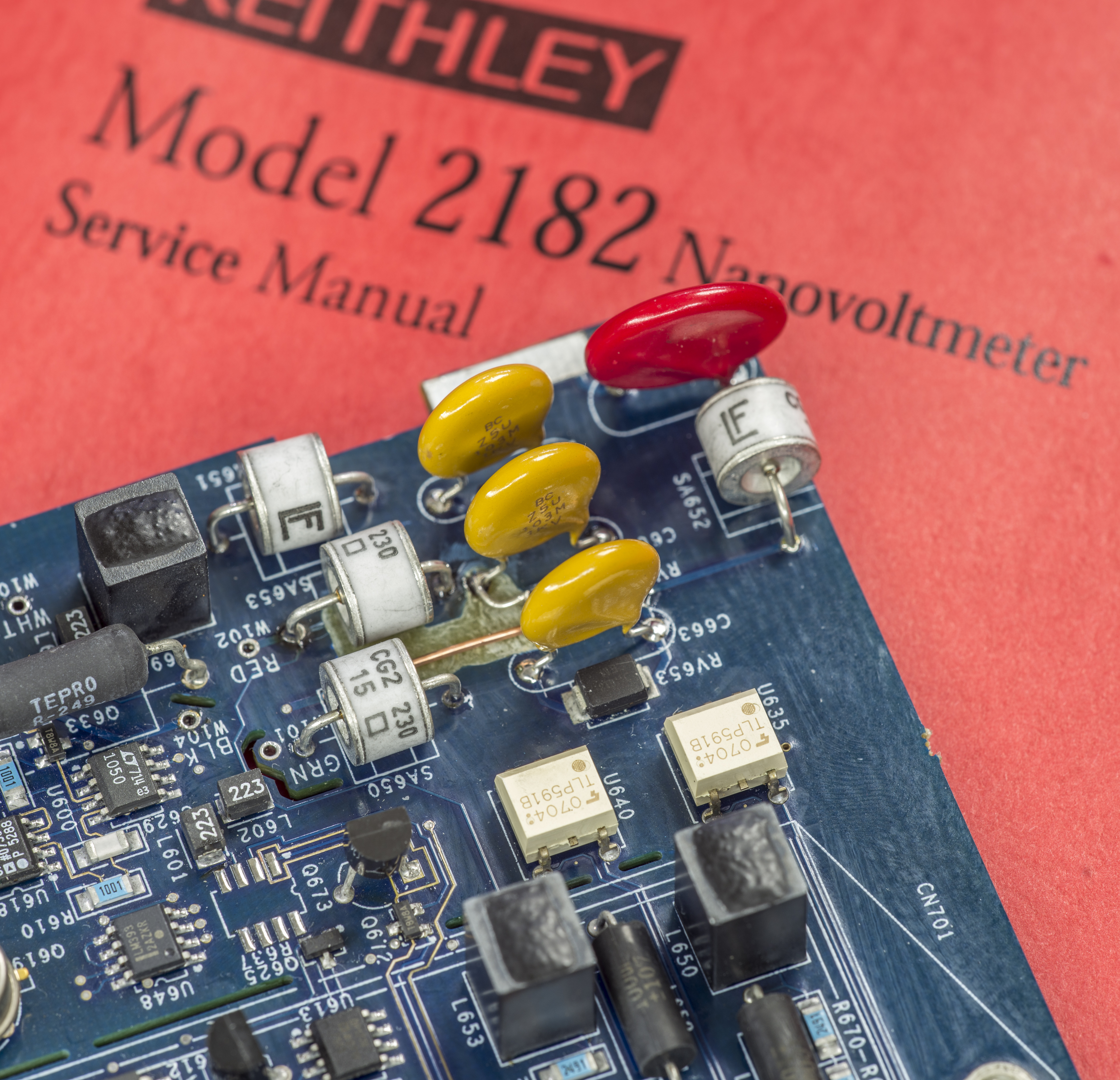
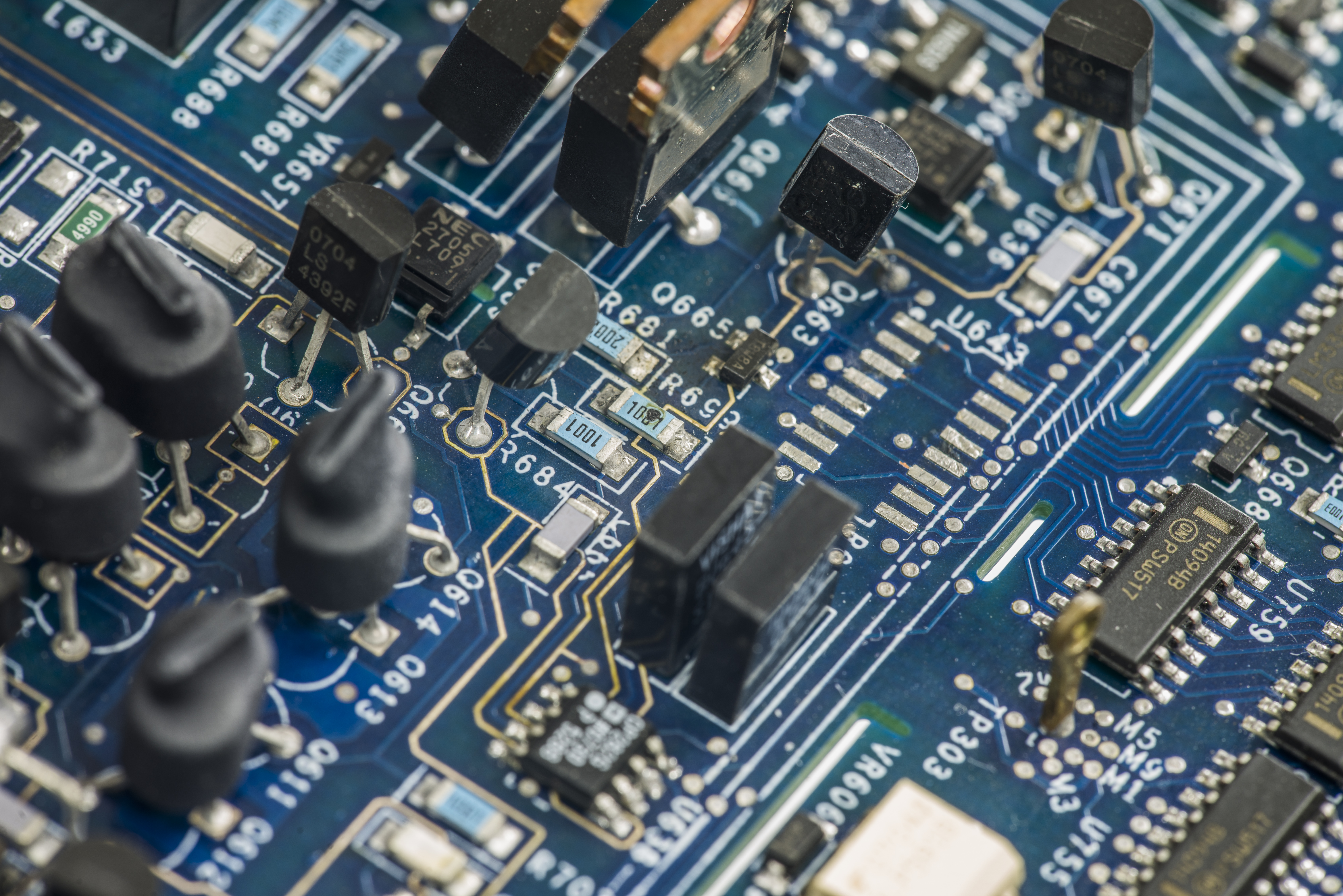
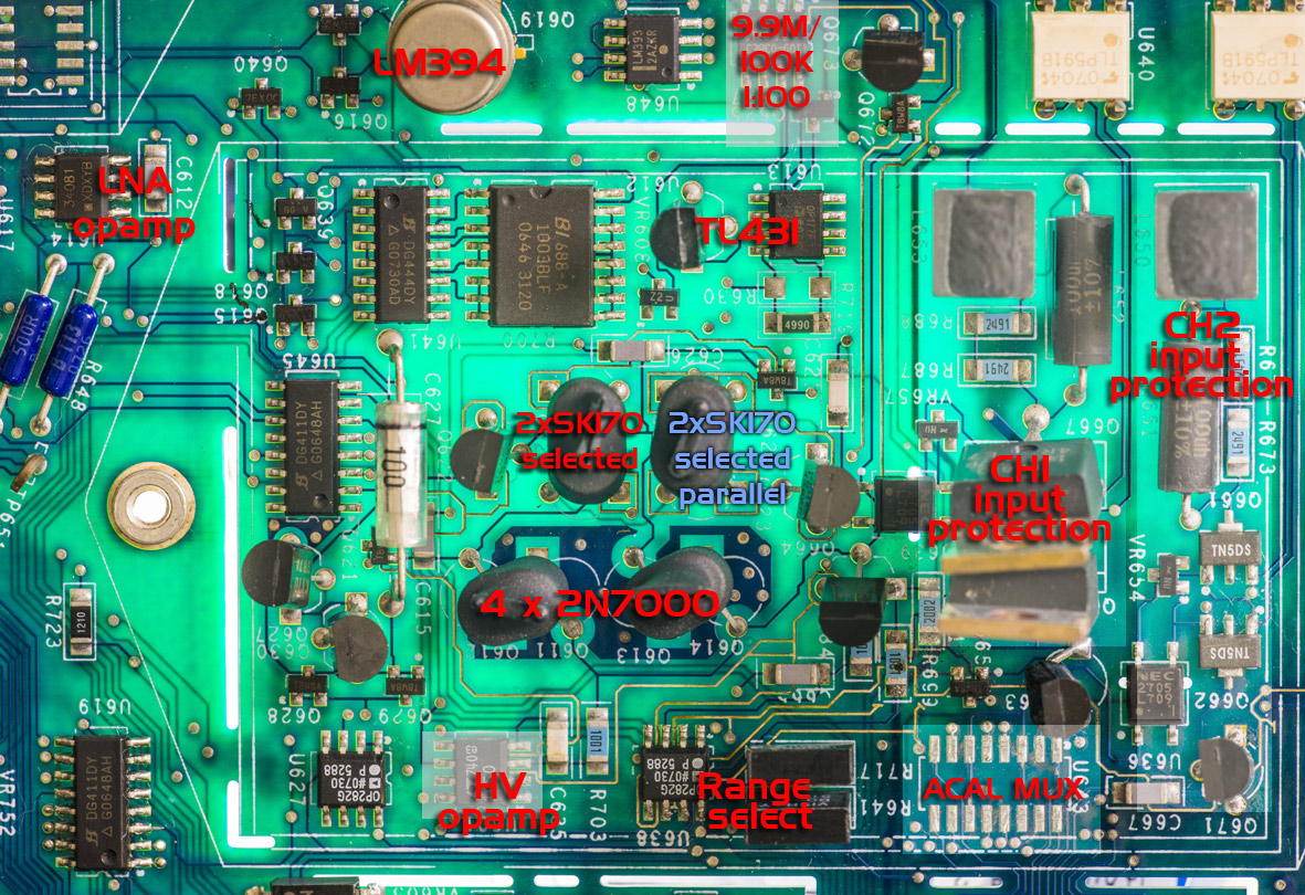
Signals from input LEMO connector are routed to PCB front-end via four wires and protected with GDT tubes and varistors, to reduce chance of damage from over-voltage conditions. Per service manual, transistors Q666 and Q667 on front-end provide protection for CH1 HI, while Q661 and Q662 provide protection for CH2 HI signal.
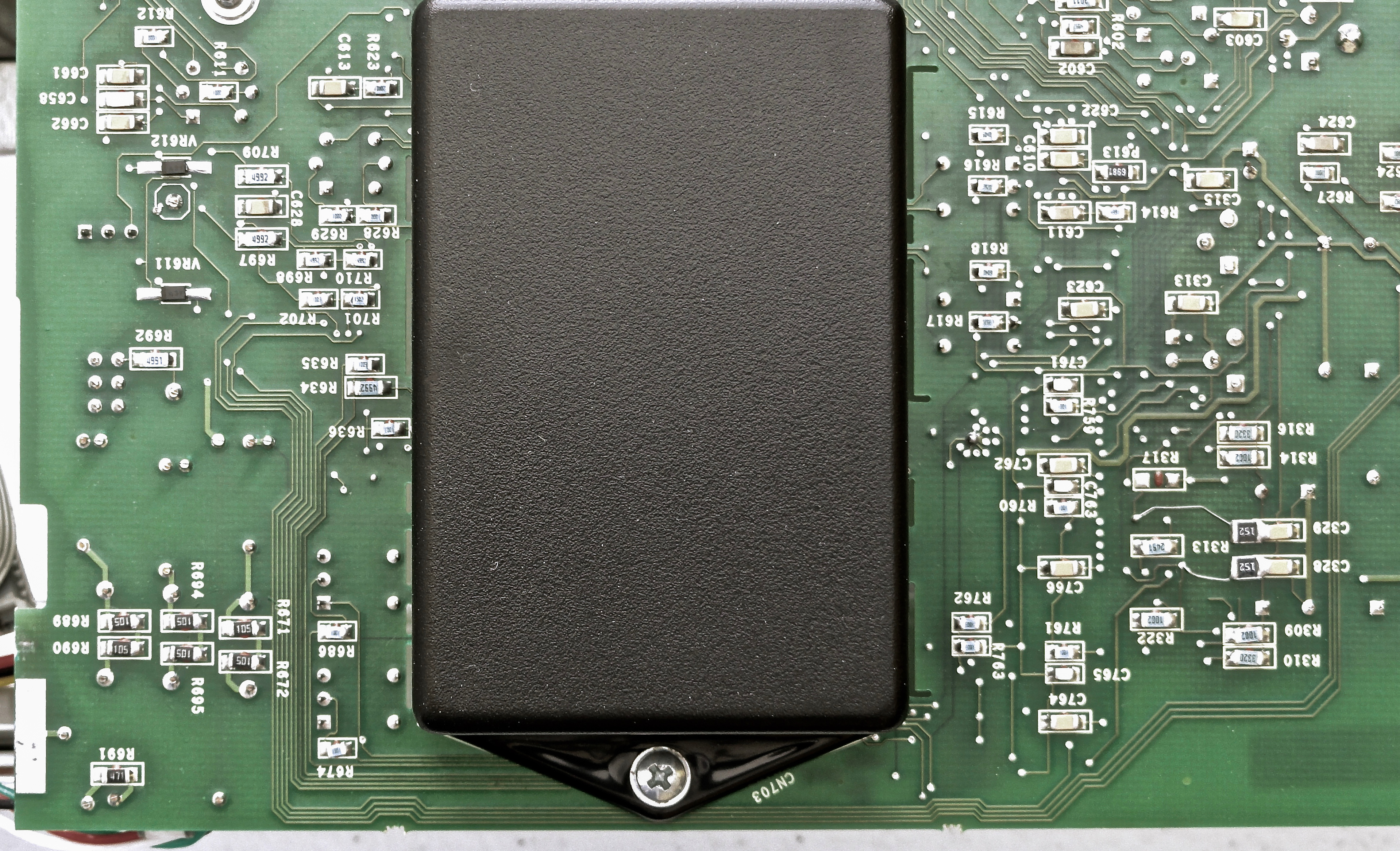
Pair of metal cans Q619 and Q652 are paired matched NPN BJTs, LM394. All low-noise analog magic and critical components of front-end is covered by big plastic covers, mounted on both sides of PCB. This is aided to avoid any stray airflow around circuits, as even small thermal gradients can generate thermal EMF, which can easily cause signal corruption on these nanovolt and microvolt levels! Great attention to detail, like shown here by Keithley is a must to guarantee circuit’s performance. These blocks also have separation on PCB by cutouts to further reduce leakage path and mechanical stresses.

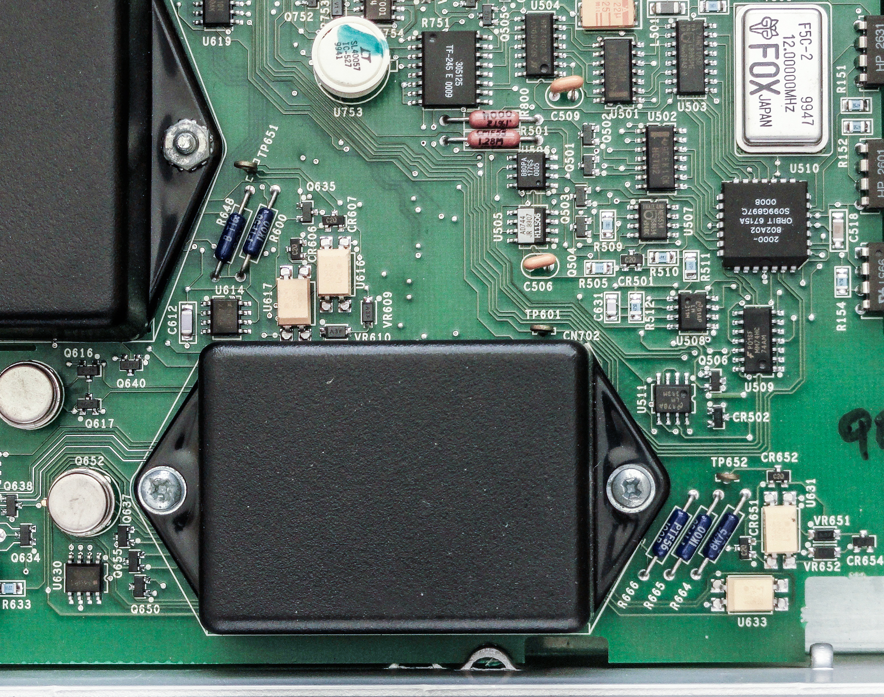
Front-end low-noise preamplifier is located under bigger box covers, so let’s take a look on it first.
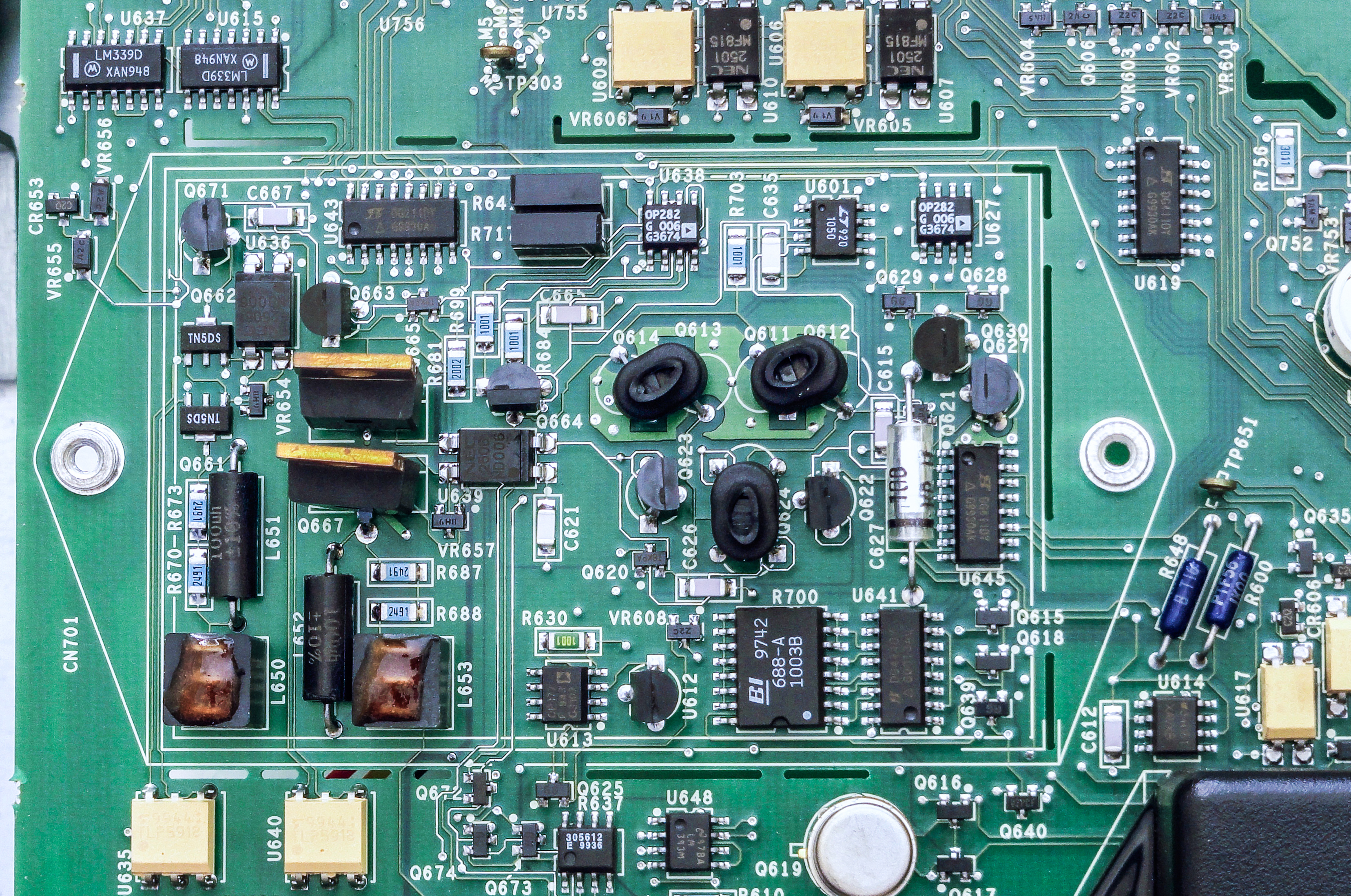
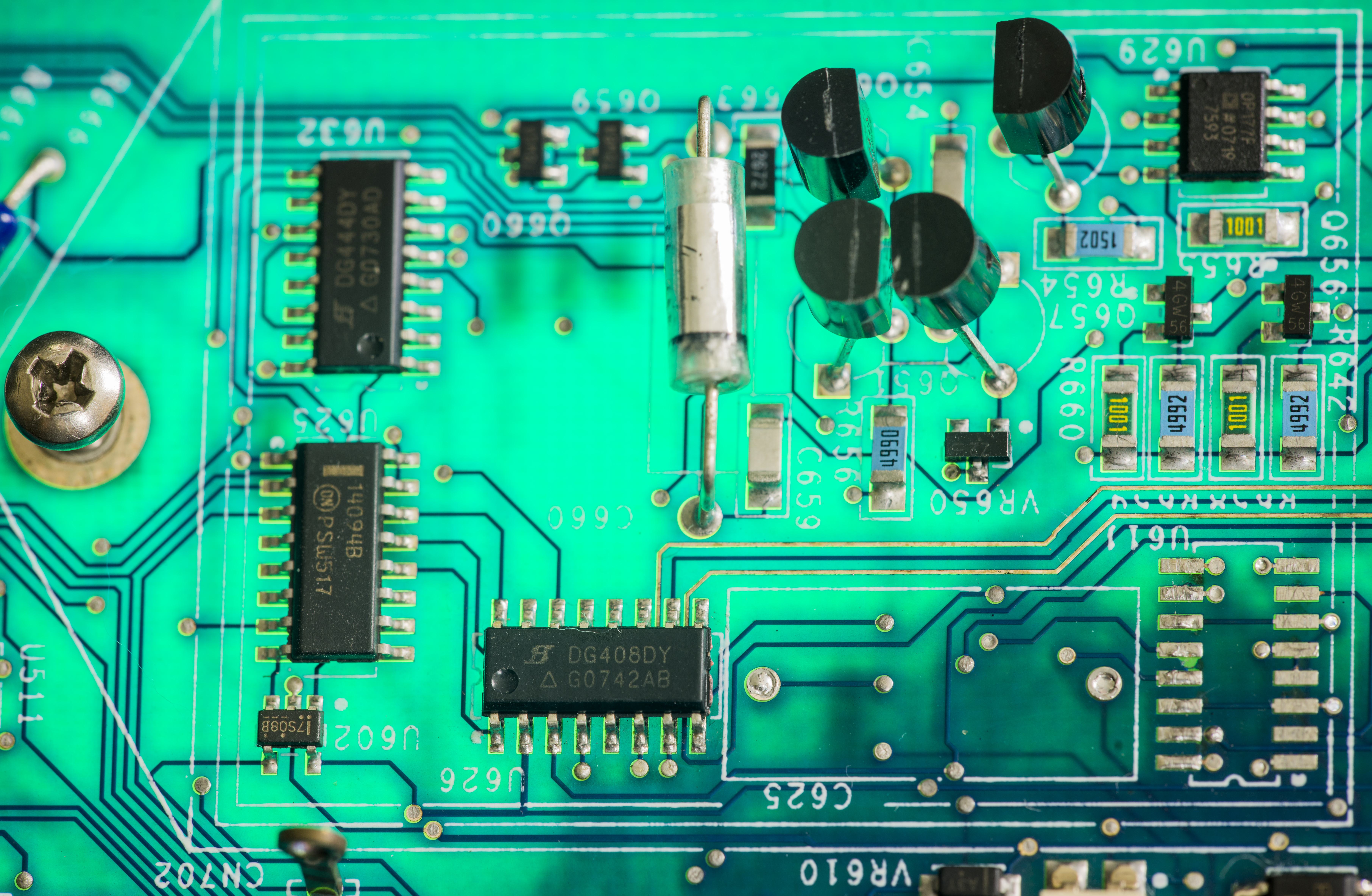
This low-noise preamp is made up of Q624, U614, and associated components. Q624 and U614 form a composite op amp with switchable gain depending on the selected measurement function. Q624 forms the differential amplifier input, while U614 provides the required high open-loop gain. Circuit gain is controlled through feedback elements and signal paths by switches Q611-Q614, Q622, Q623, and U645. Selected Q624 have Keithley’s own part number 2010-600A, which hints for it’s use in 7½-digit 2010 DMM as well.
U601 is a unity-gain amplifier that provides signal buffering for the divider common signal path. A 100:1 resistive divider is switched in to attenuate the signal for the 100V range.
There is 10 KΩ precision network from BI, R700, as well as metal film SMT resistors R670, R673, R687, R688, R681, R699, R684, and pair of 100 Ω Vishay foil resistors R641 and R717 with tolerance 0.05%.

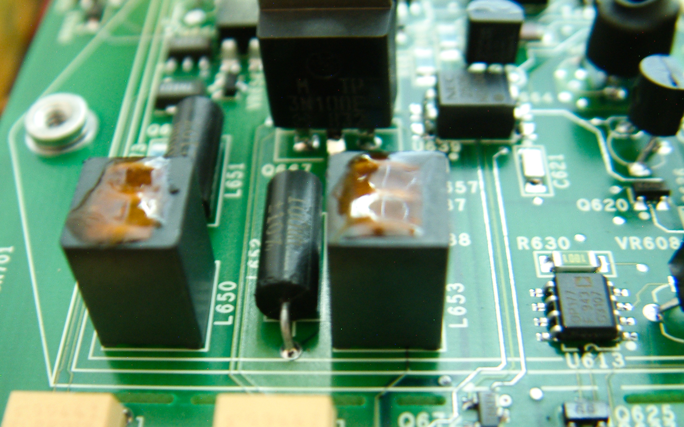
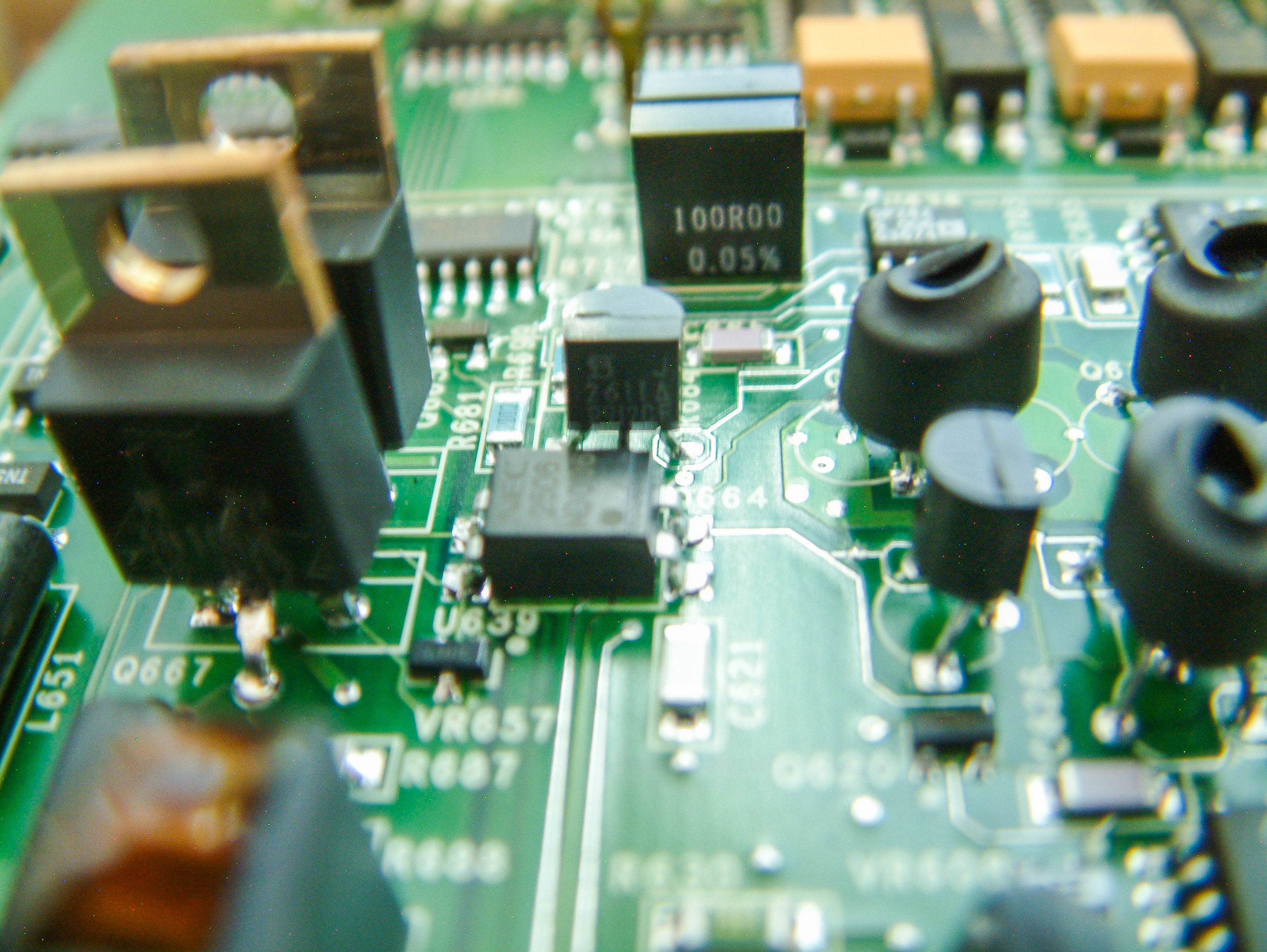
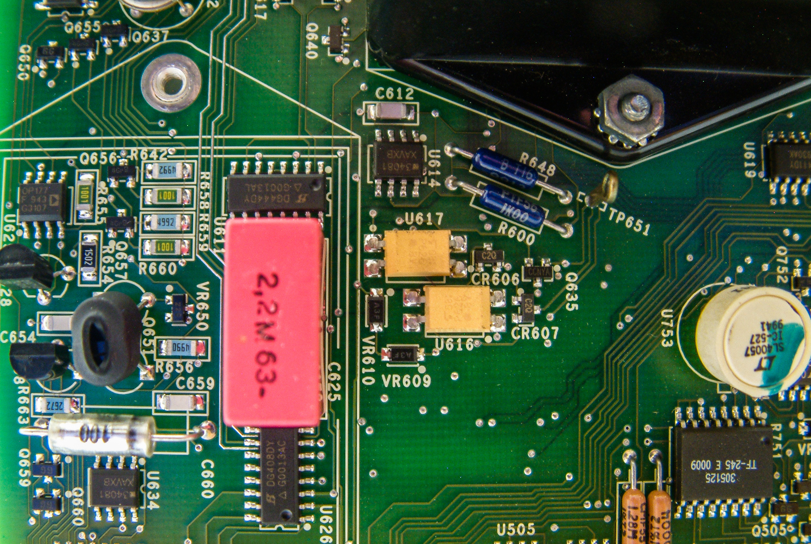
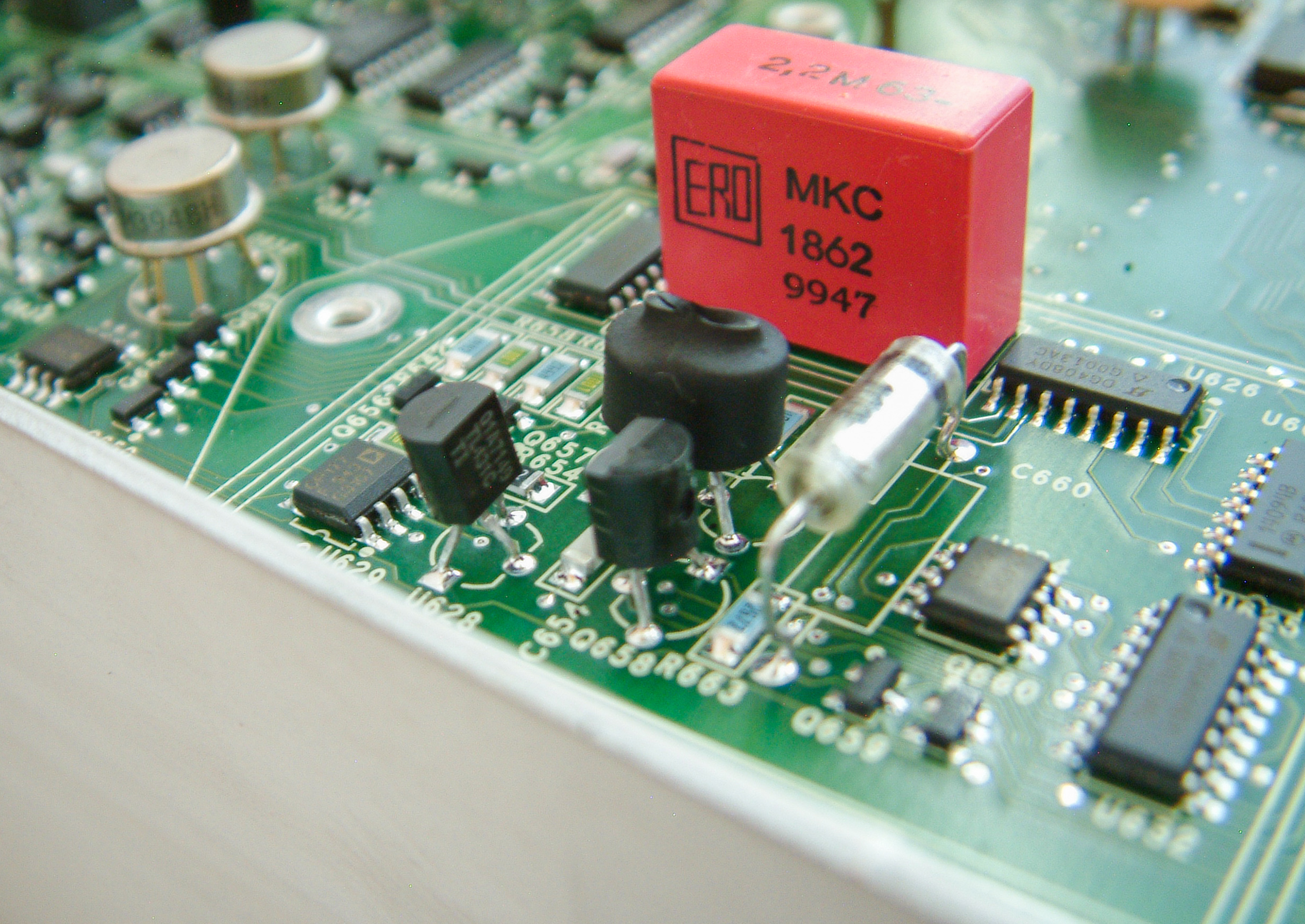
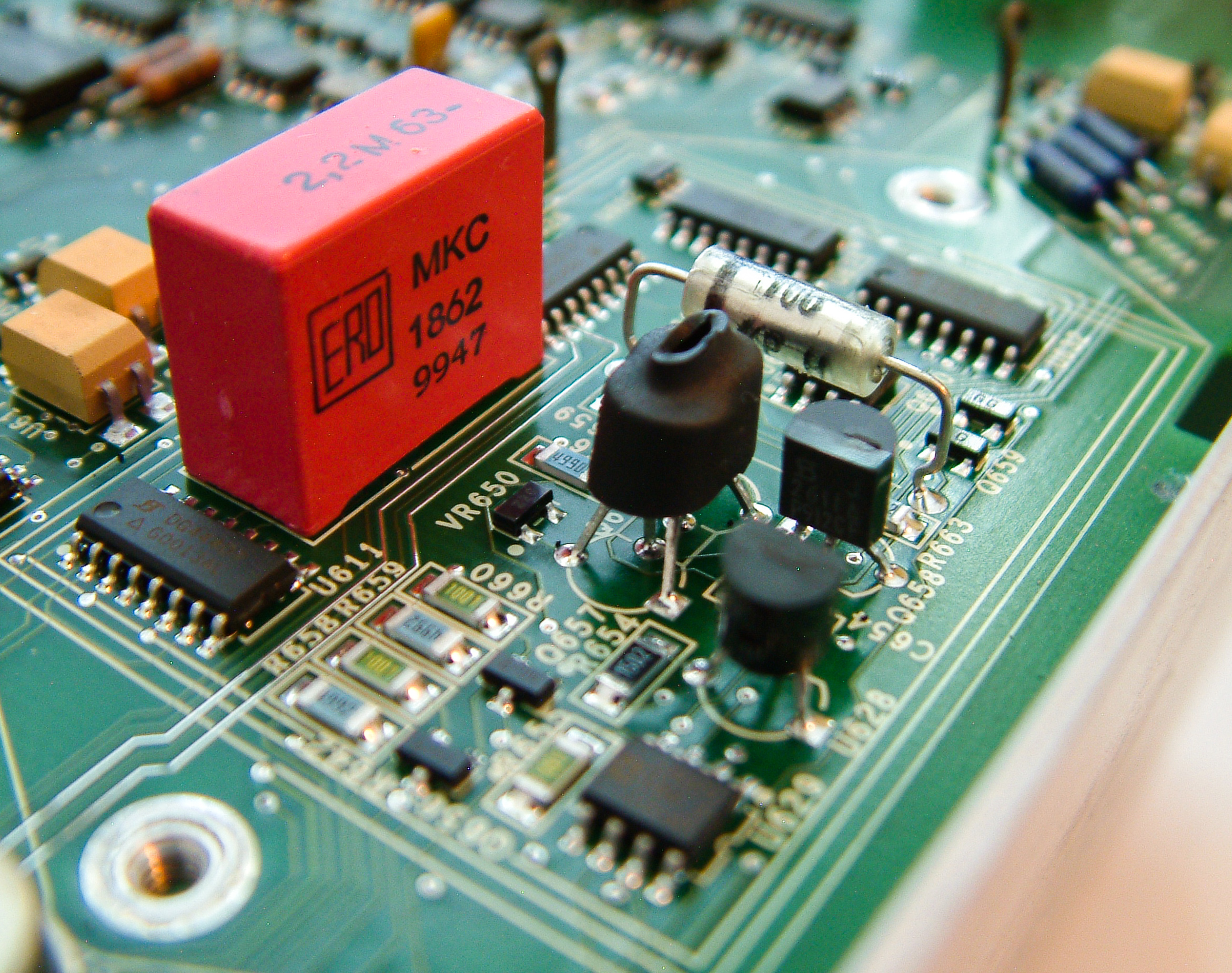
Second smaller box protects ADC’s gain amplifier from airflow.
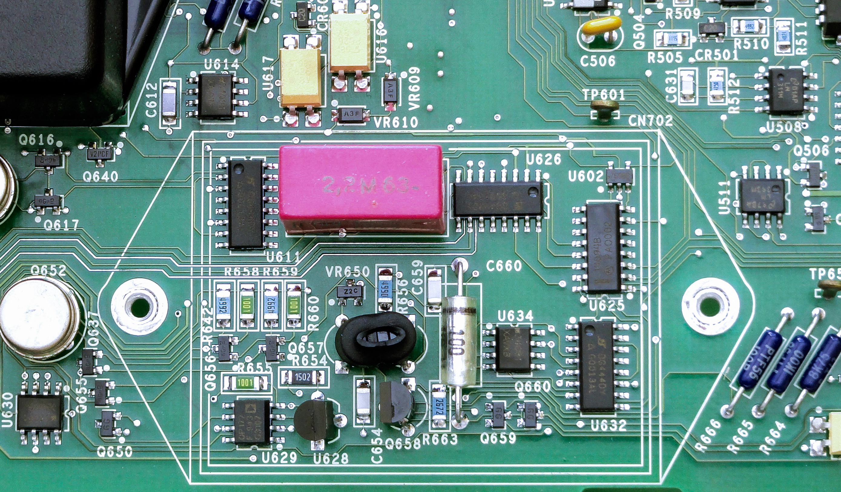
There are some passives and big polycarbonate film 2.2µF capacitor.
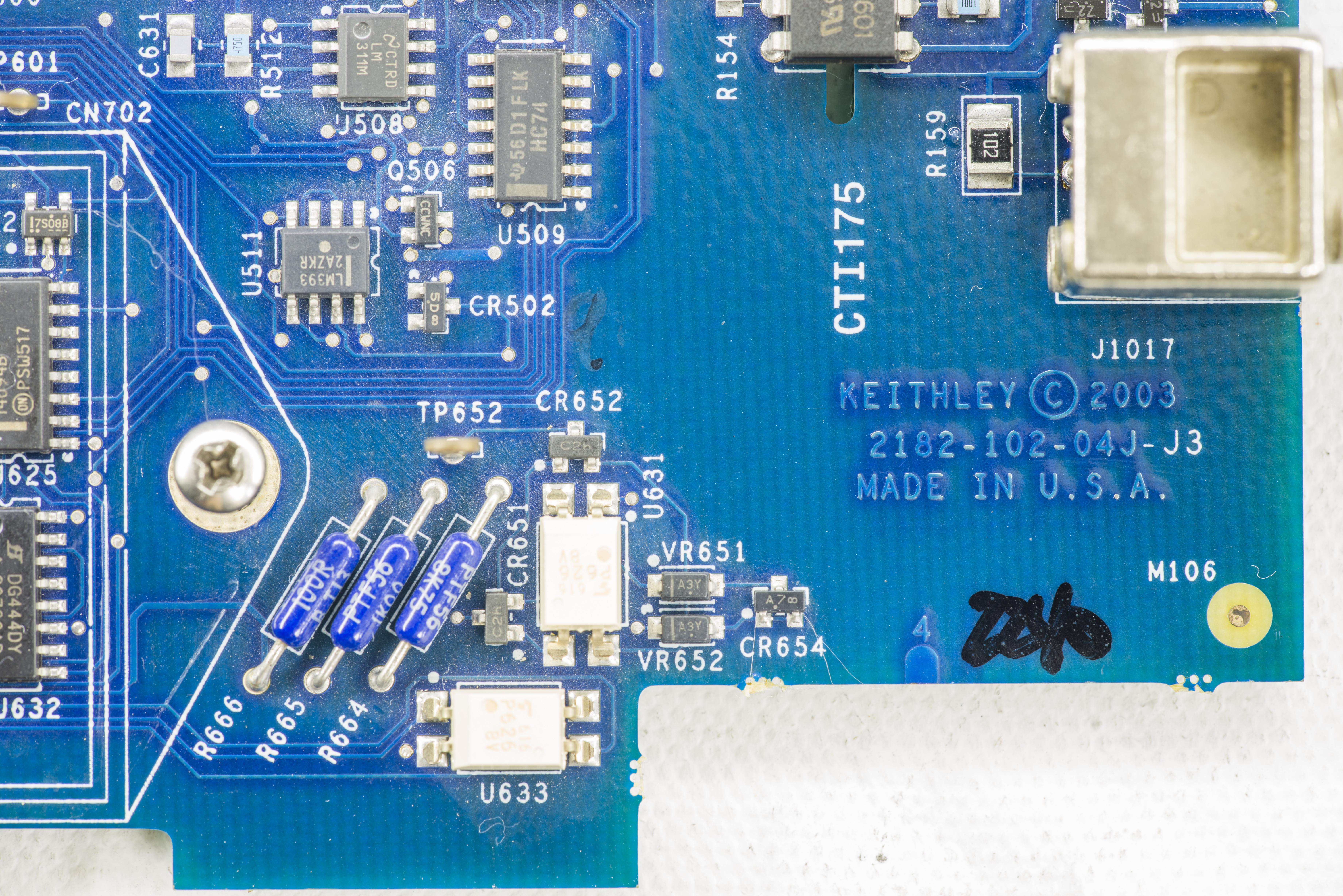
Our FR4 PCB have Keithley’s model number 2182-102-01E, meaning Revision E.
Few more photos of bottom side:

Model 2182 Repair workflow
| Step | Item/component | Required condition | Remarks |
|---|---|---|---|
| 1 | Function | DCV1 | Use DCV1 for measurements |
| 2 | Input connections | CH1 HI and LO | Connect voltage source to CH1 |
| 3 | Measurement range | 100V | Select 100V range |
| 4 | Input voltage | 100V | Apply 100V to CH1 input |
| 5 | U601 pin 6 | +1V | Buffer output |
| 6 | TP652 | +10V | Multiplexer output to A/D |
| 7 | Measurement range | 10V | Select 10V range |
| 8 | Input voltage | +10V | Apply 10V to CH1 input |
| 9 | TP651 | +10V | Preamp output |
| 10 | TP652 | +10V | Multiplexer output to A/D |
| 11 | Measurement range | 1V | Select 1V range |
| 12 | Input voltage | +1V | Apply 1V to CH1 input |
| 13 | TP651 | +1V | Preamp output |
| 14 | TP652 | +10V | Multiplexer output to A/D |
| 15 | Measurement range | 100mV | Select 100mV range |
| 16 | Input voltage | +100mV | Apply 100mV to CH1 input |
| 17 | TP651 | +100mV | Preamp output |
| 18 | TP652 | +10V | Multiplexer output to A/D |
| 19 | Measurement range | 10mV | Select 10mV range |
| 20 | Input voltage | +10mV | Apply 10mV to CH1 input |
| 21 | TP651 | +1V | Preamp output |
| 22 | TP652 | +10V | Multiplexer output to A/D |
Table 3: Analog circuit checks
Model 2182A Initial inspection and basic disassembly
Now the exciting part, the exploded “A”-version meter. My favourite type of repair attempts, making something out of what looks completely unfixable.


Based on teardown the differences between older and newer generations are summarized as below:
| Circuit | Model 2182 | Model 2182A | Reason |
|---|---|---|---|
| Main JFET low-noise amplifier | Single selected 2SK170 pair | Dual selected 2SK170 pairs | LNA improvement to lower the noise |
| ACAL LNA circuitry | Post-LNA ACAL only | Both front-end and preamp ACAL | Better coverage and accuracy for whole signal path |
| Flash ROMs | Firmware upgrade require service | Field upgradeable firmware | Easier maintenance |
| 6221-2182 Delta-mode support | Since FW version A10 | All meters support natively | Better integration |
Model 2182A Repair workflow
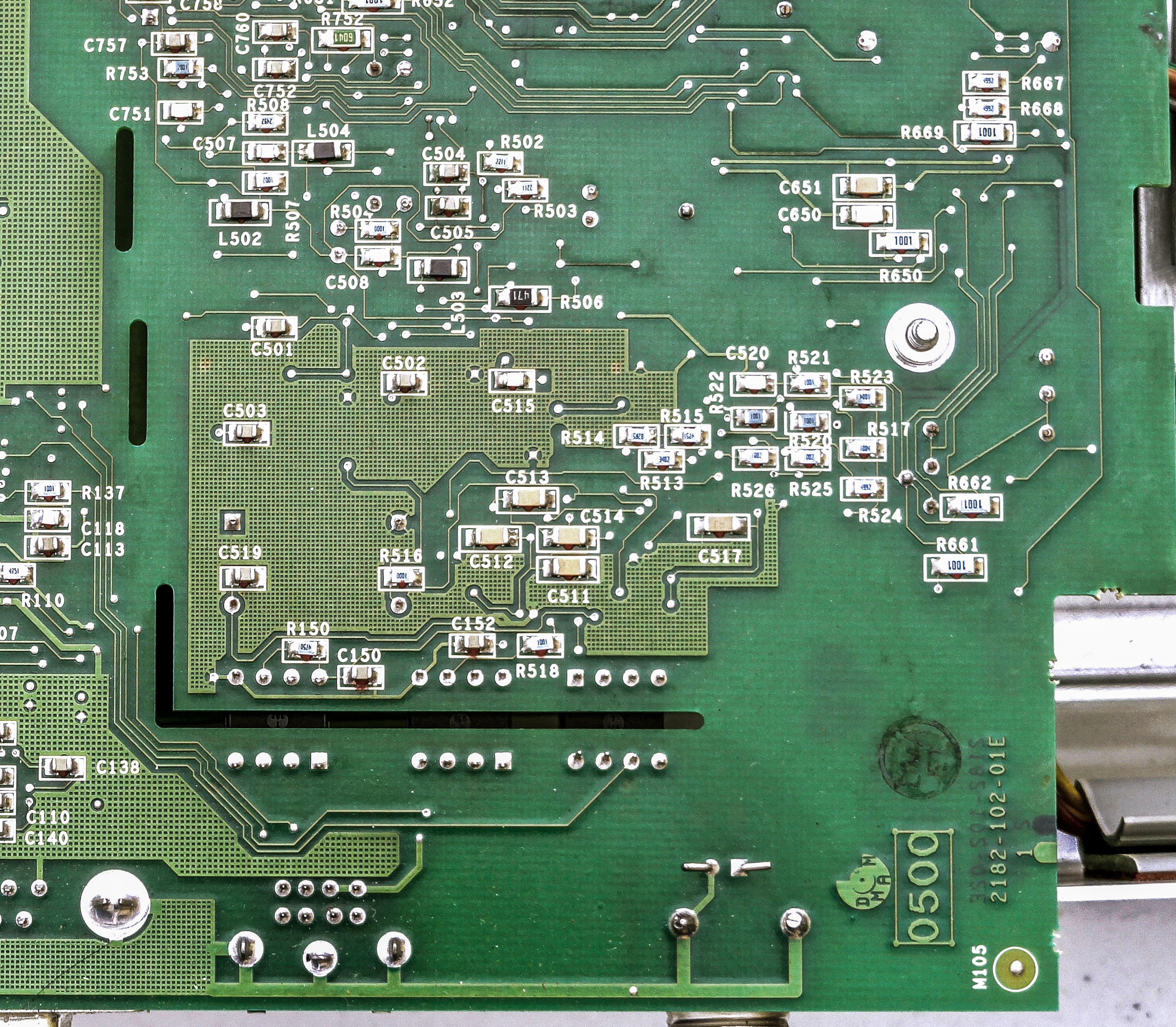
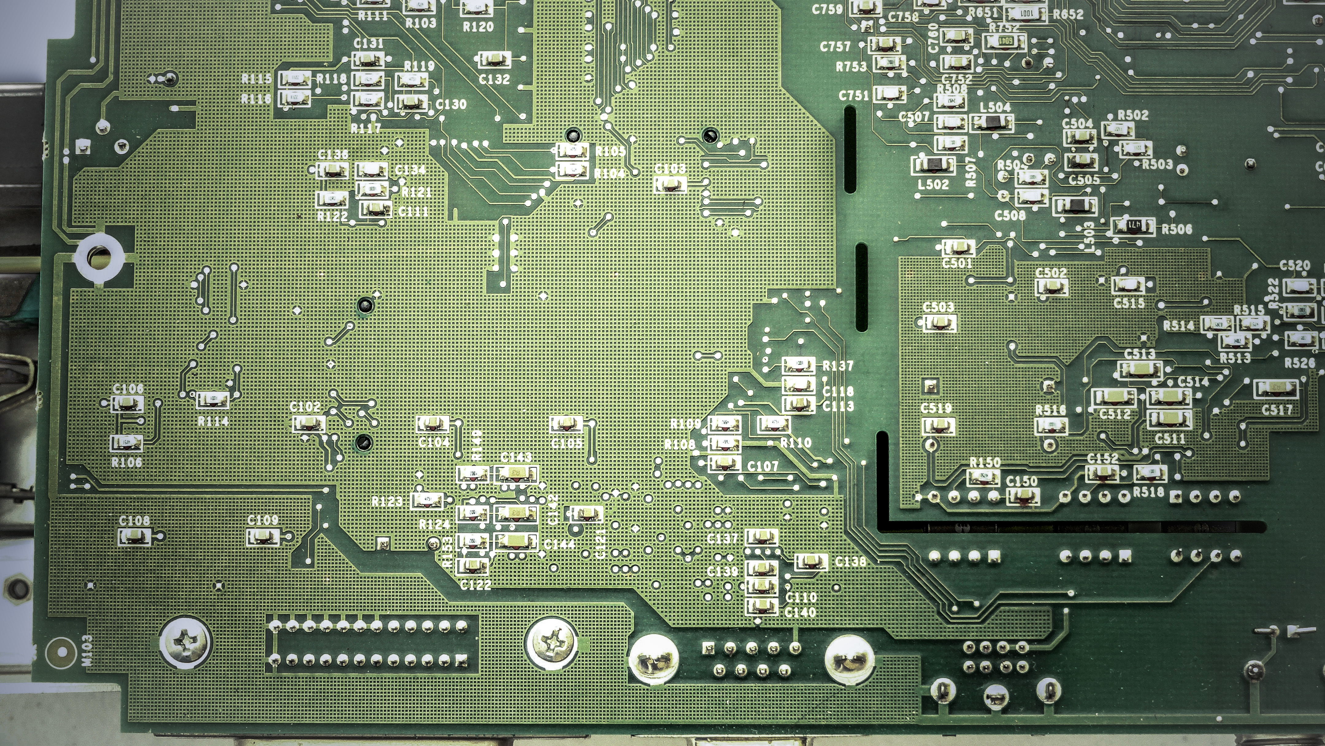
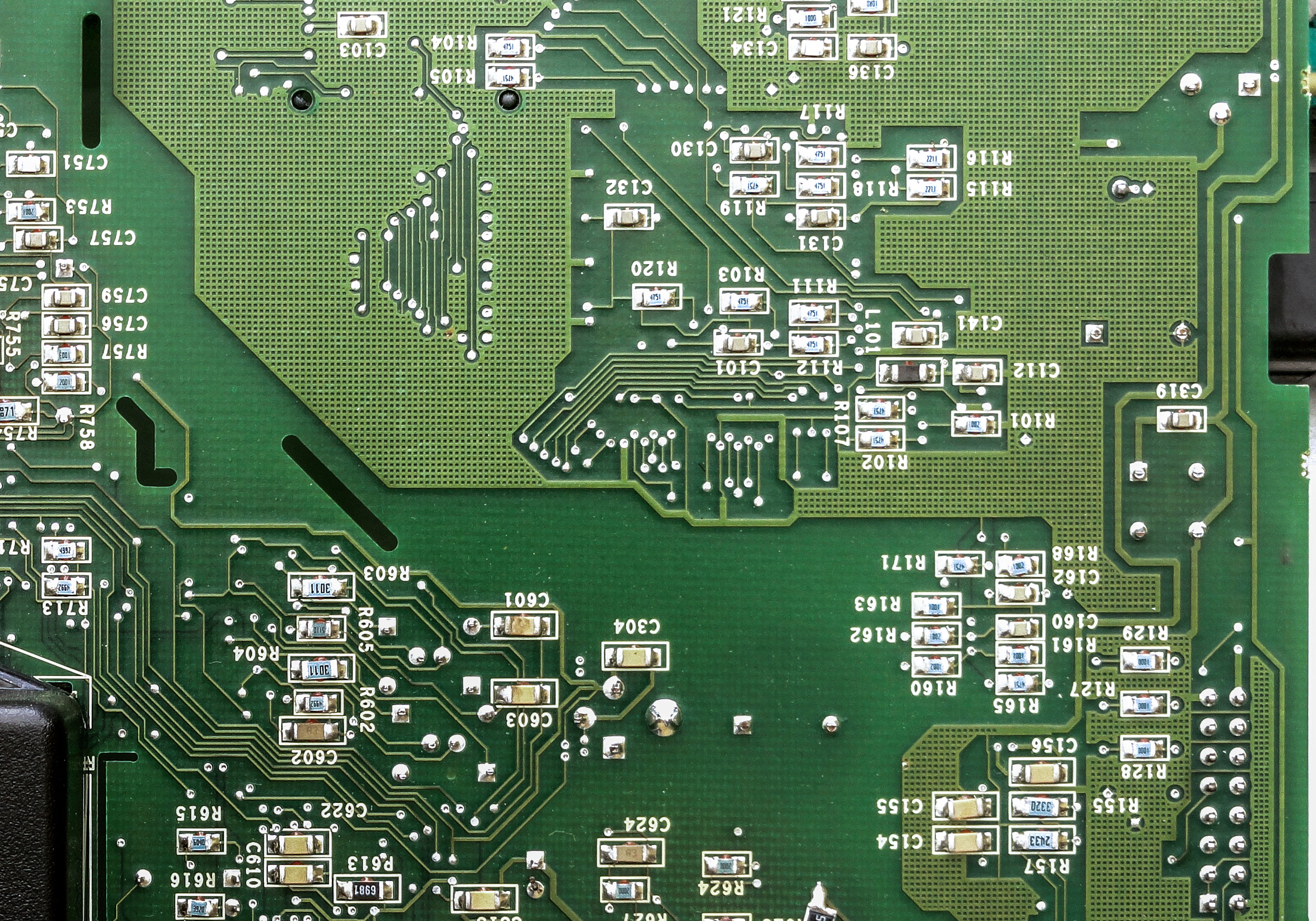
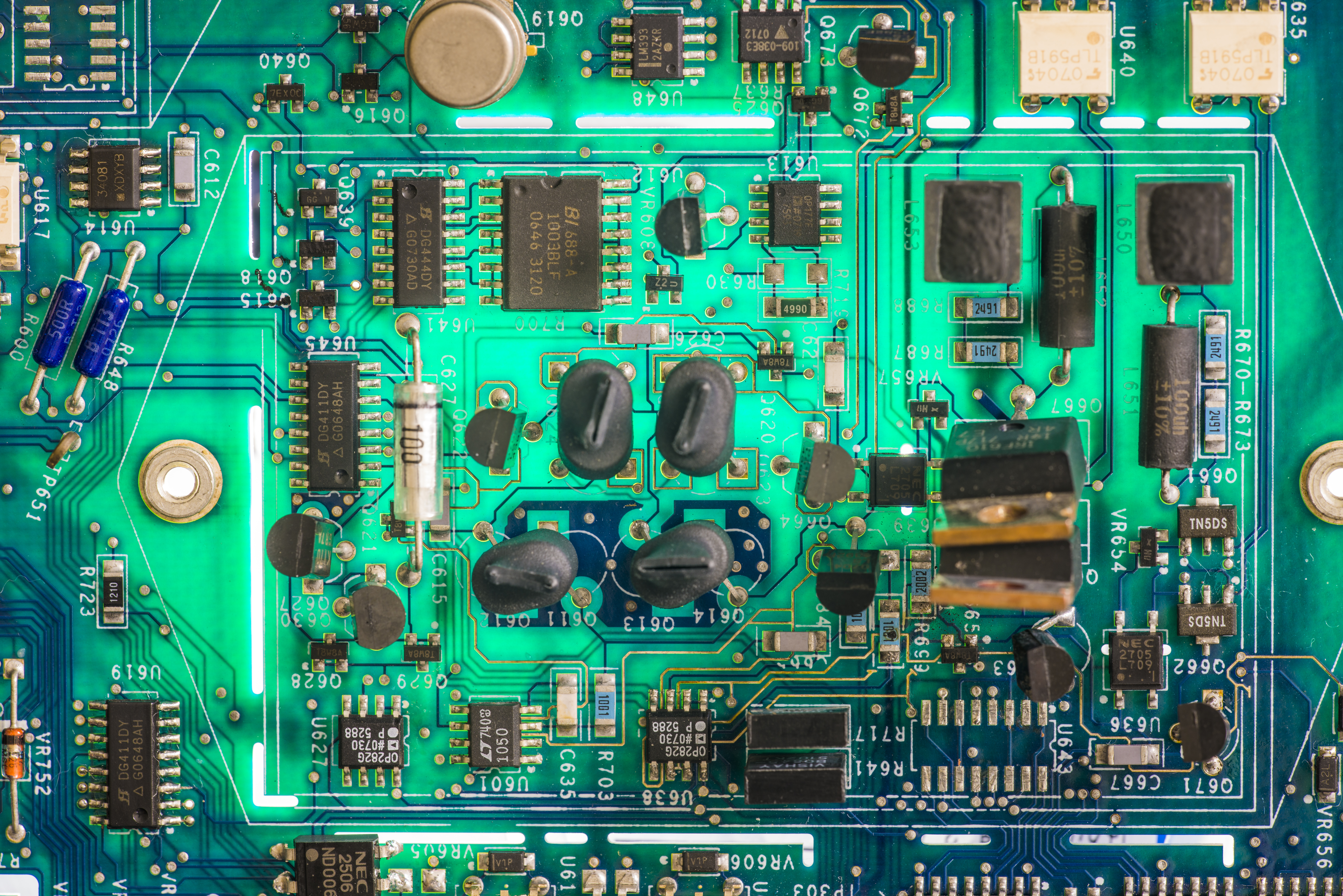
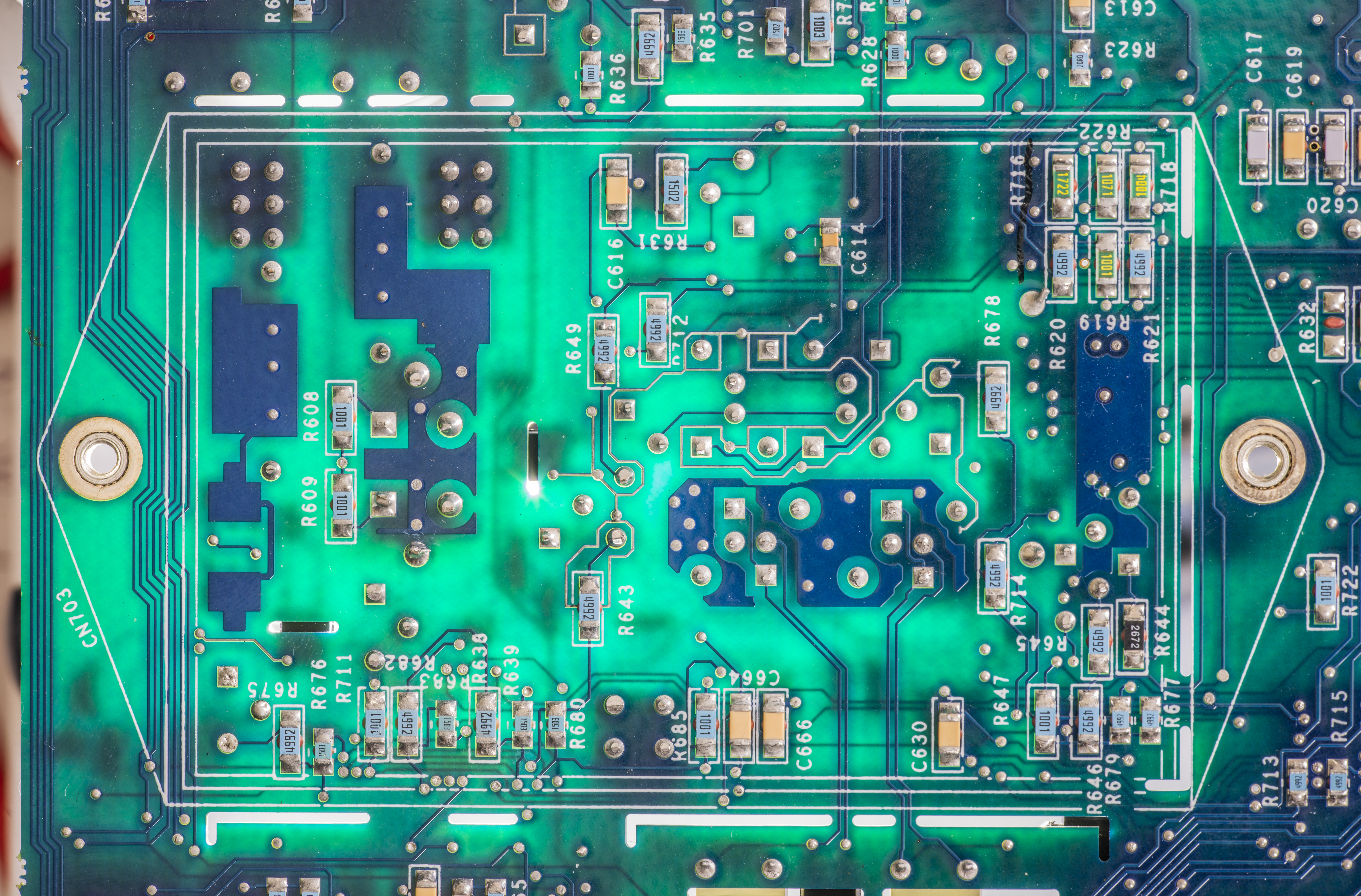
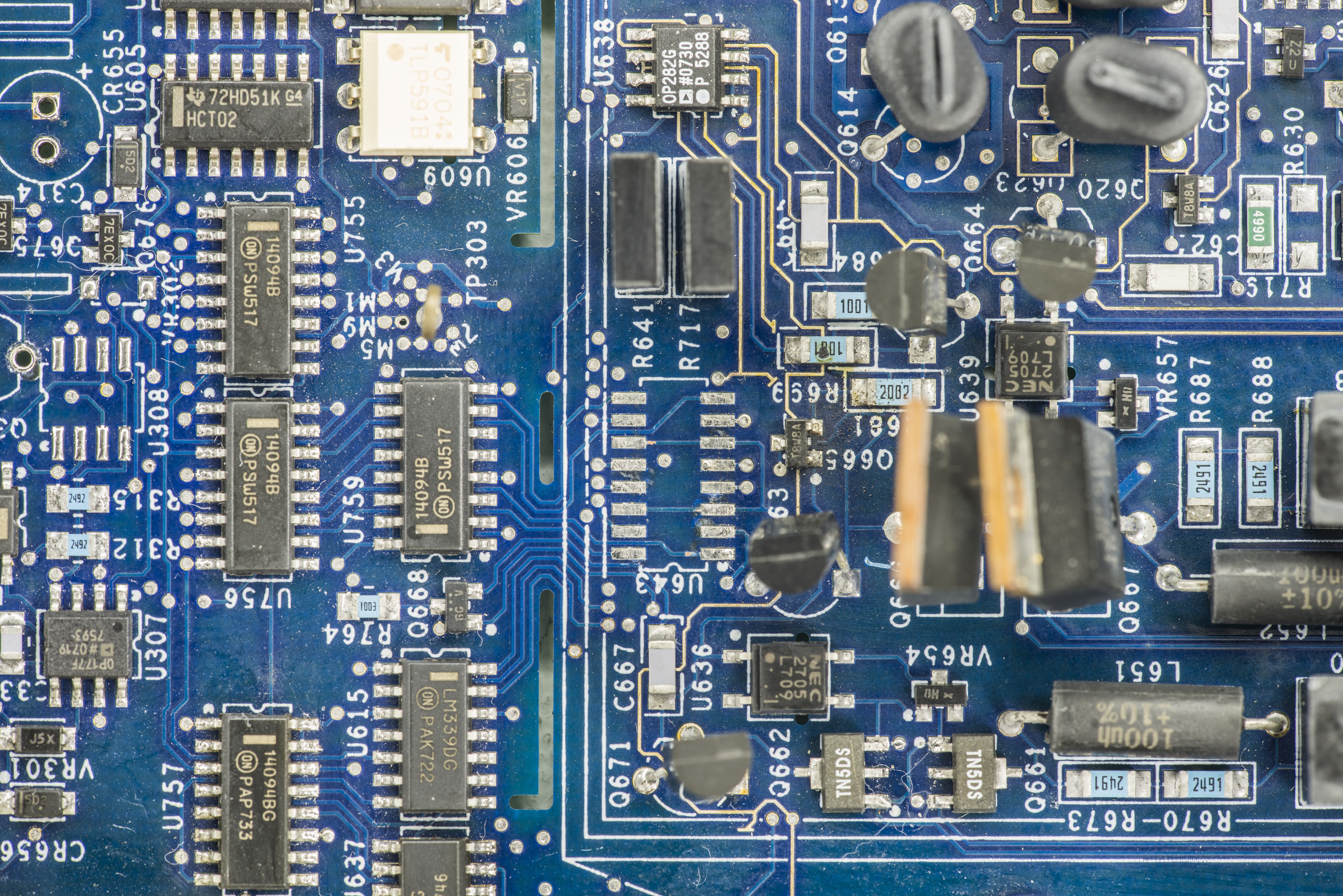
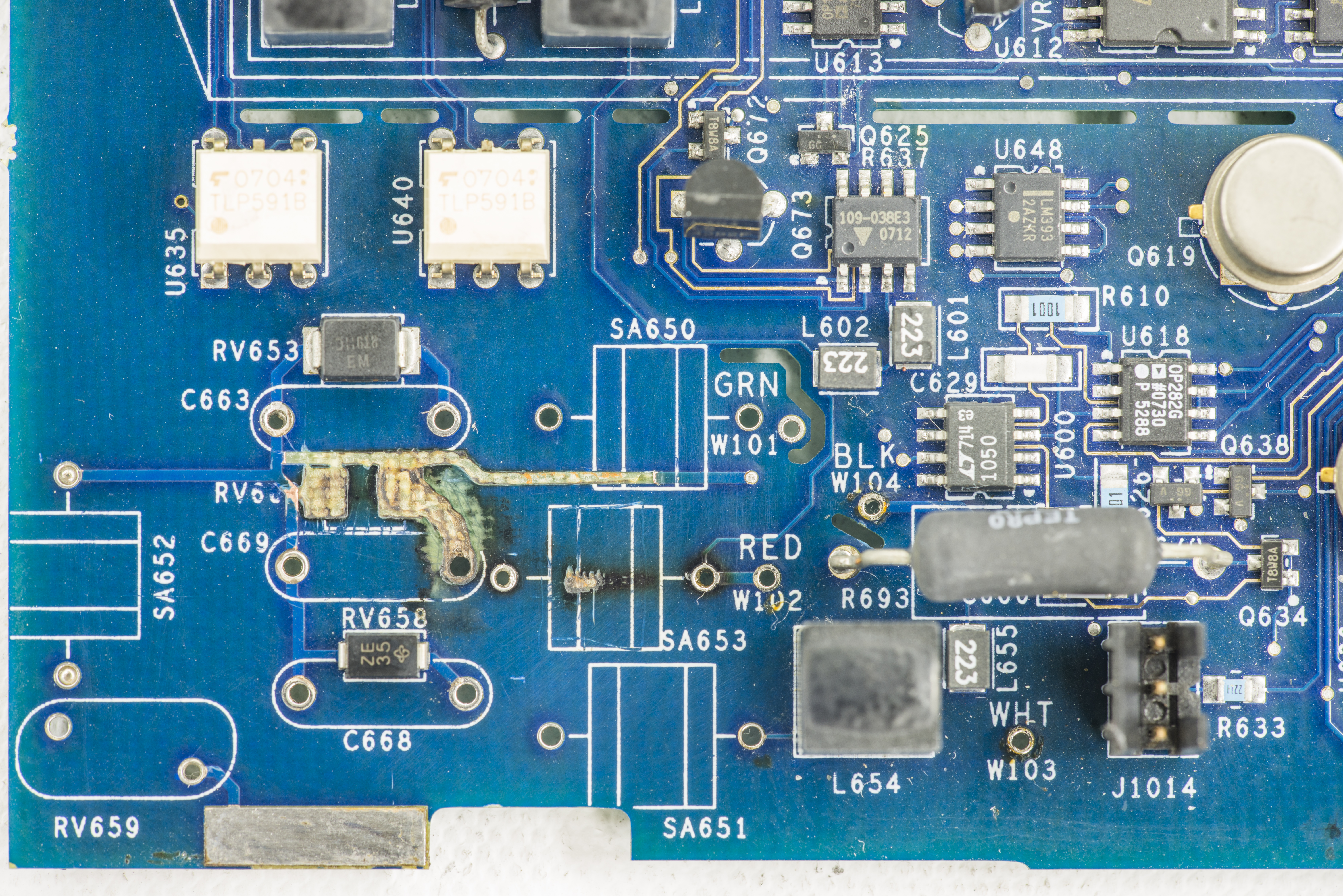
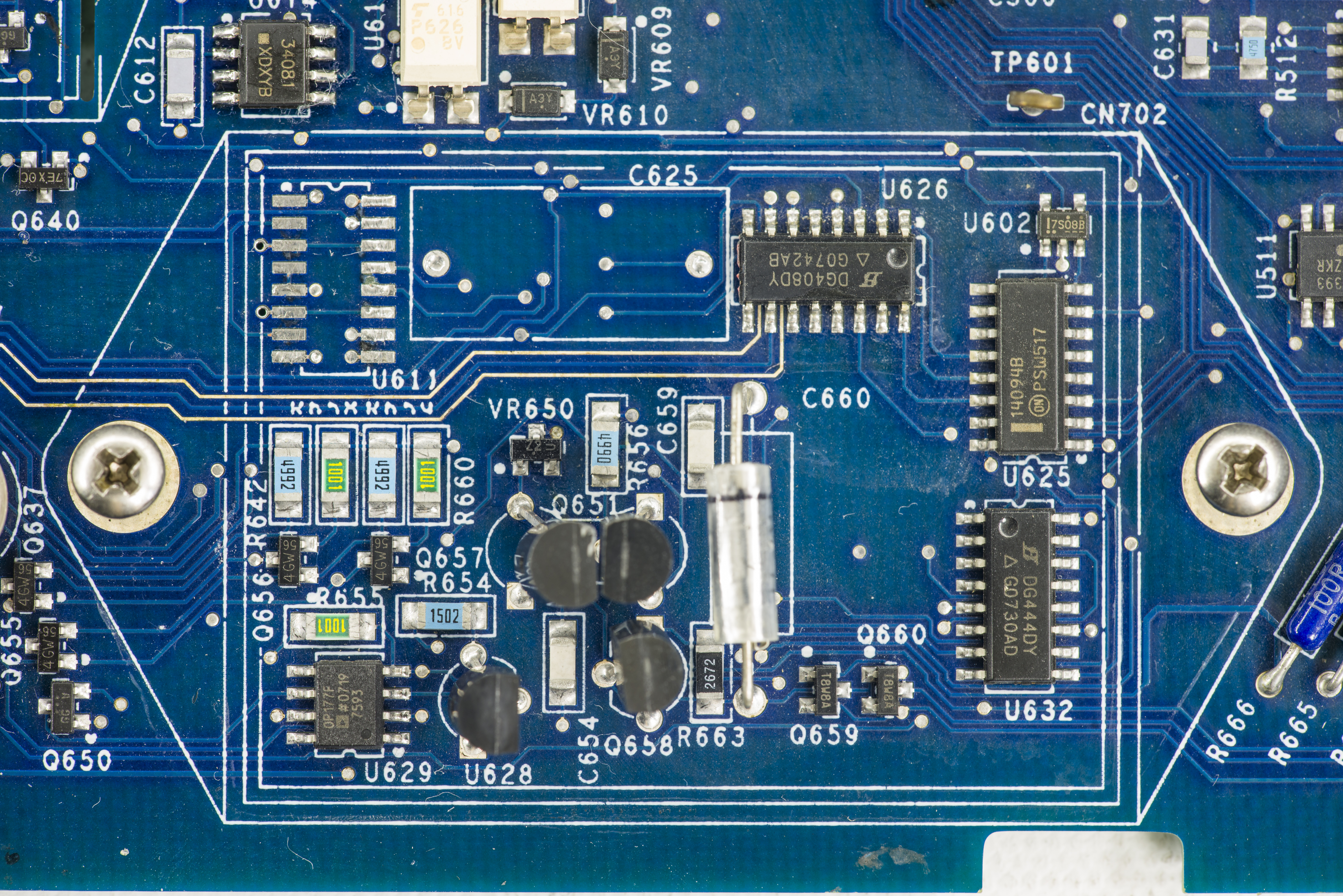
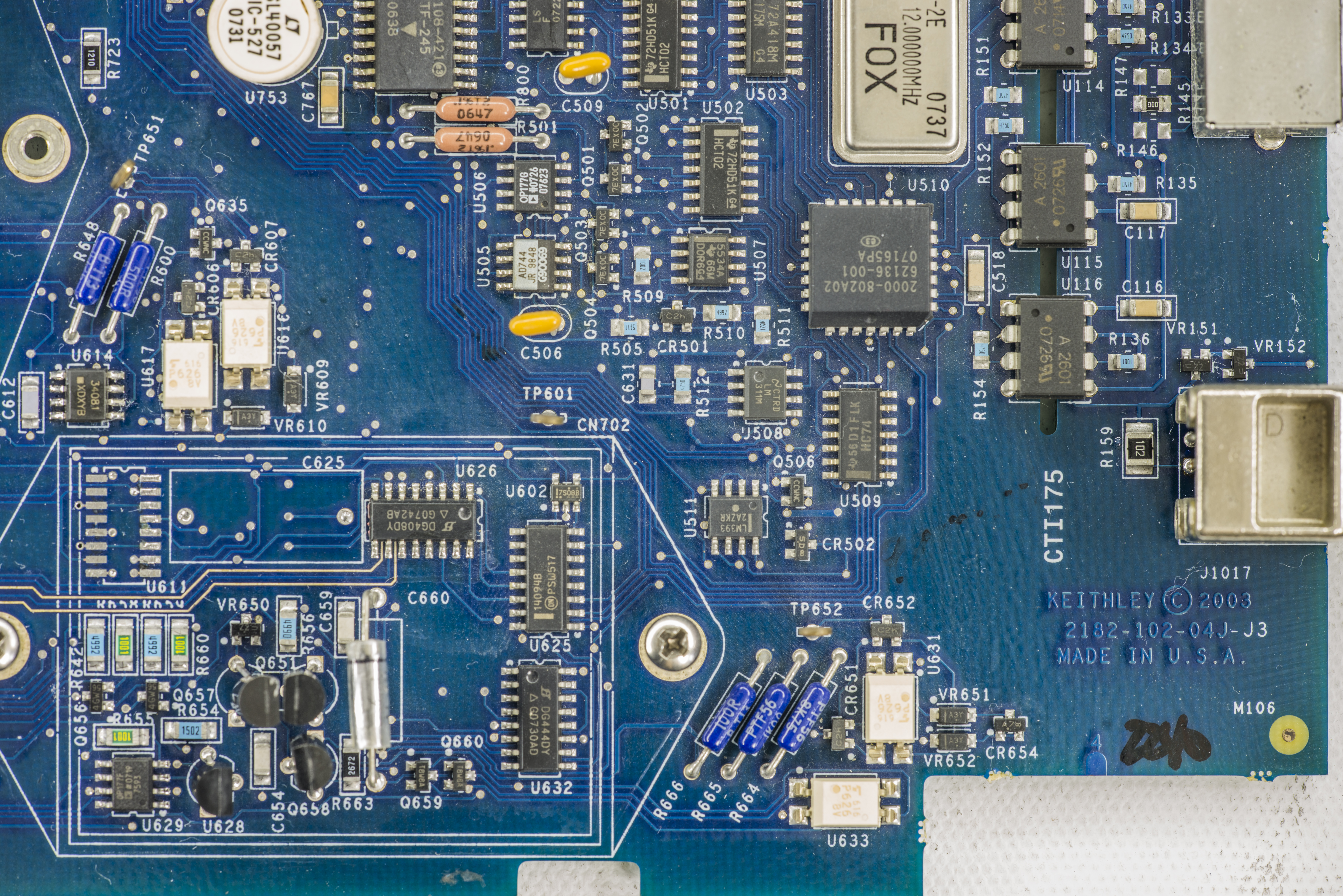
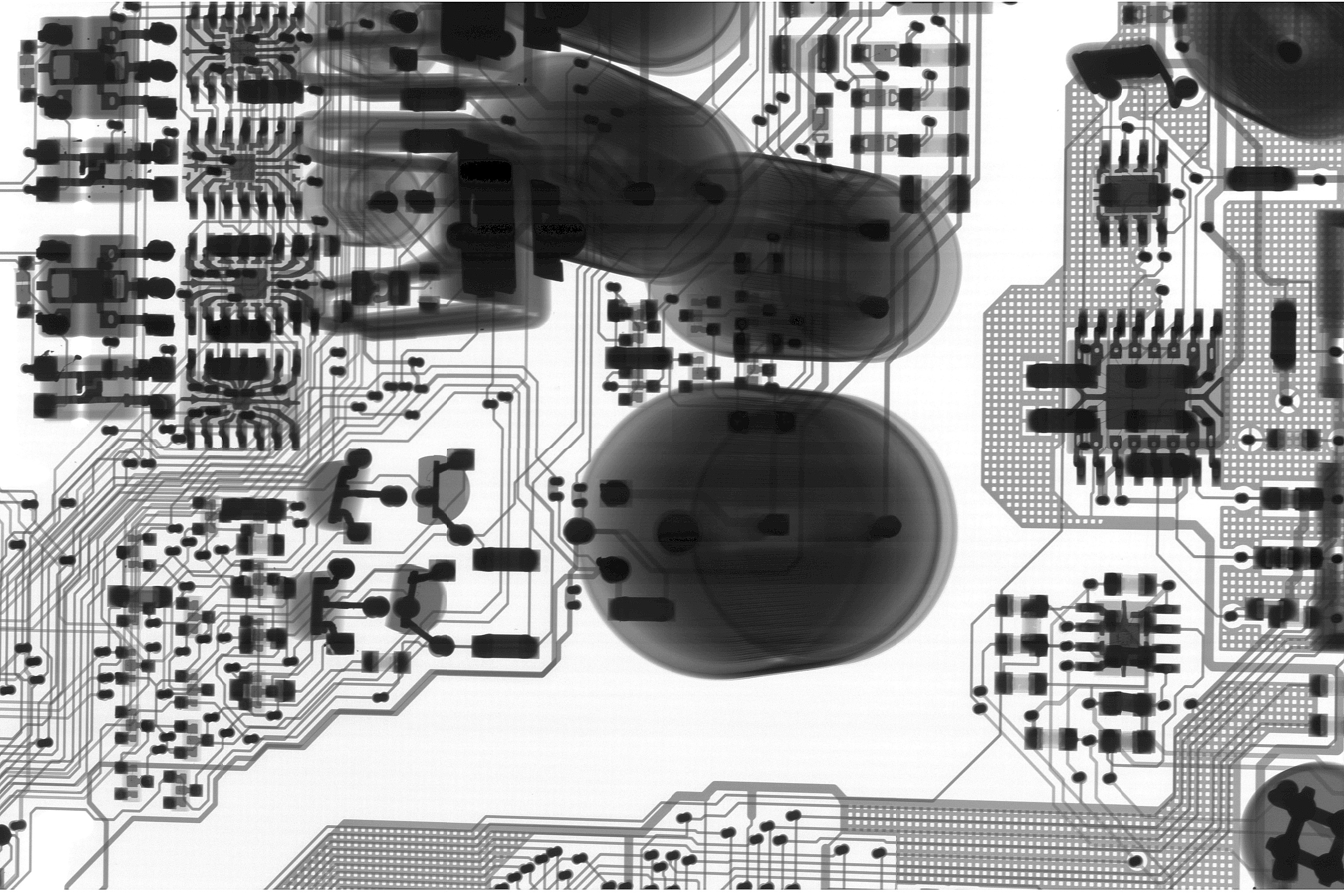
Model 2182A PCB images
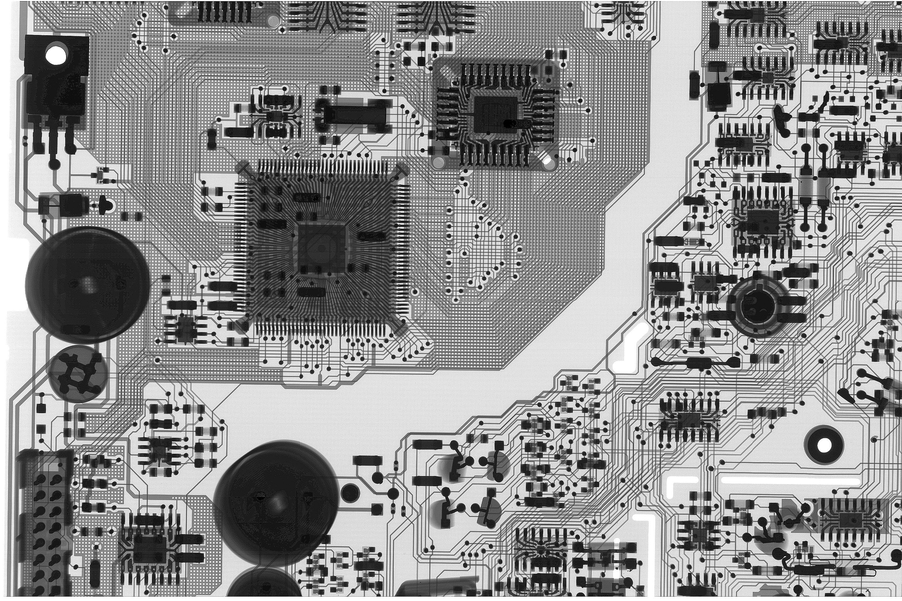
Additional hi-resolution images in transparent mode reveal routing and leadframes inside of the chips. Digital PCB section shows shielding polygons as well as inner routing of various controller sections:
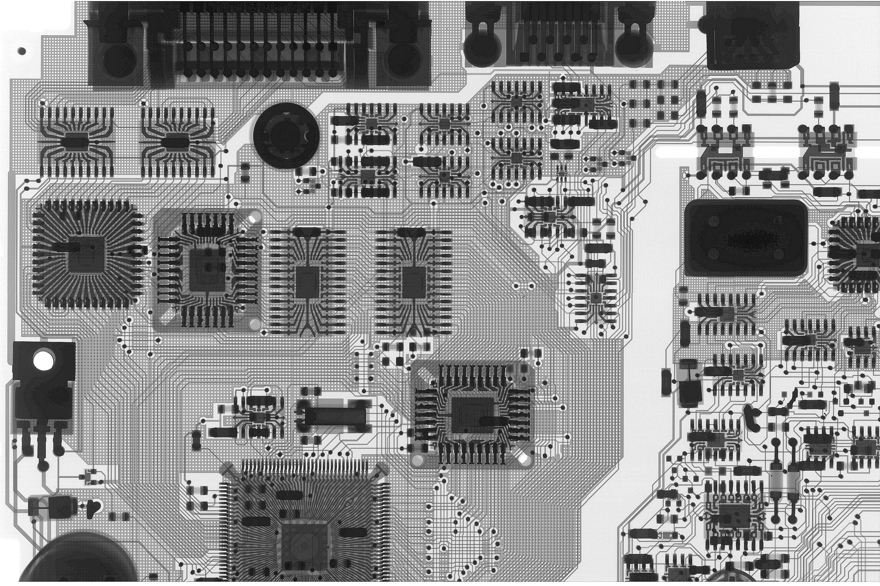
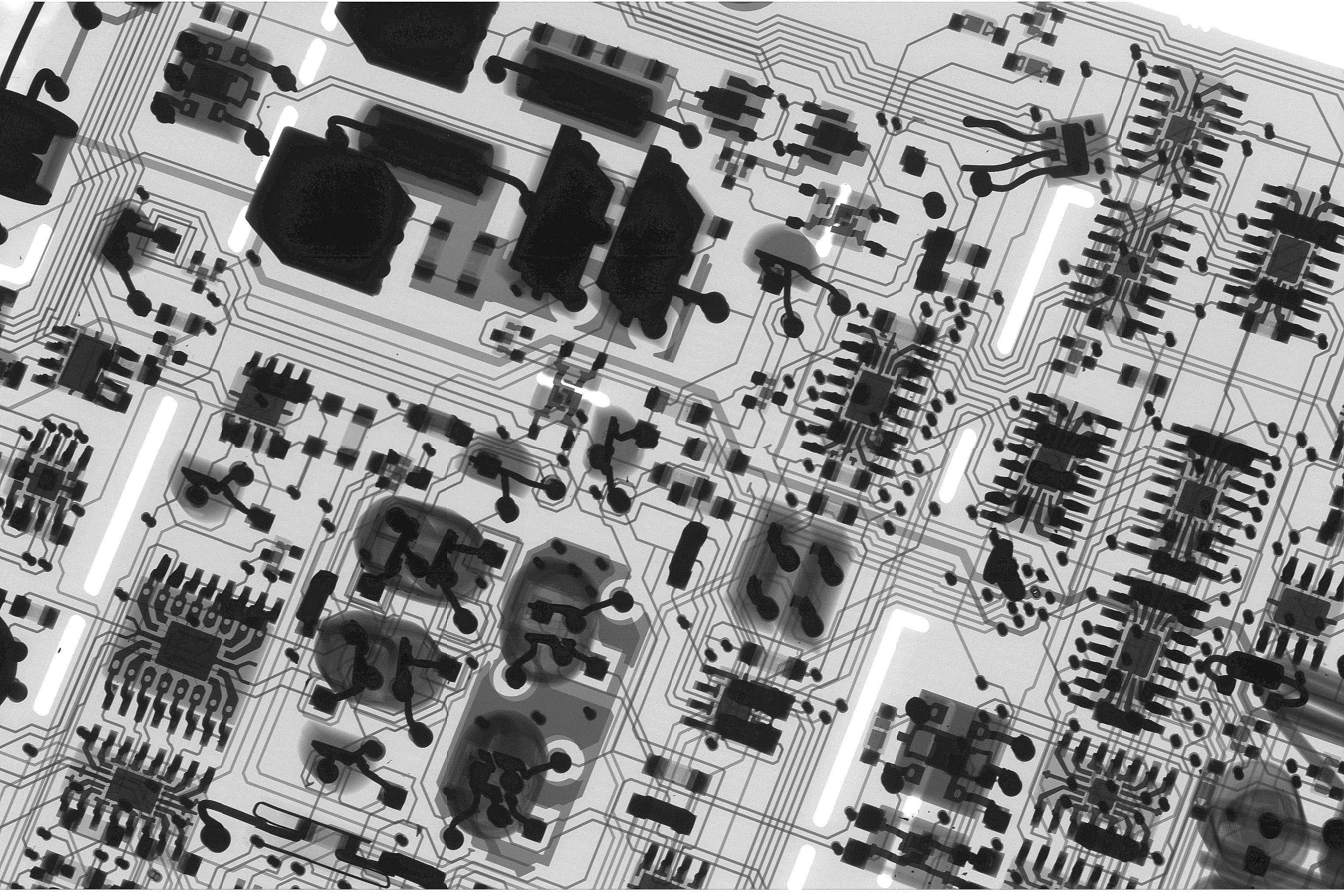
Analog section does not have copper fills or grounding as it is often counterproductive in precision analog design due to added parasitic capacitances and possibility of noise propagation to sensitive nodes from the large power planes. ADC and reference sections:
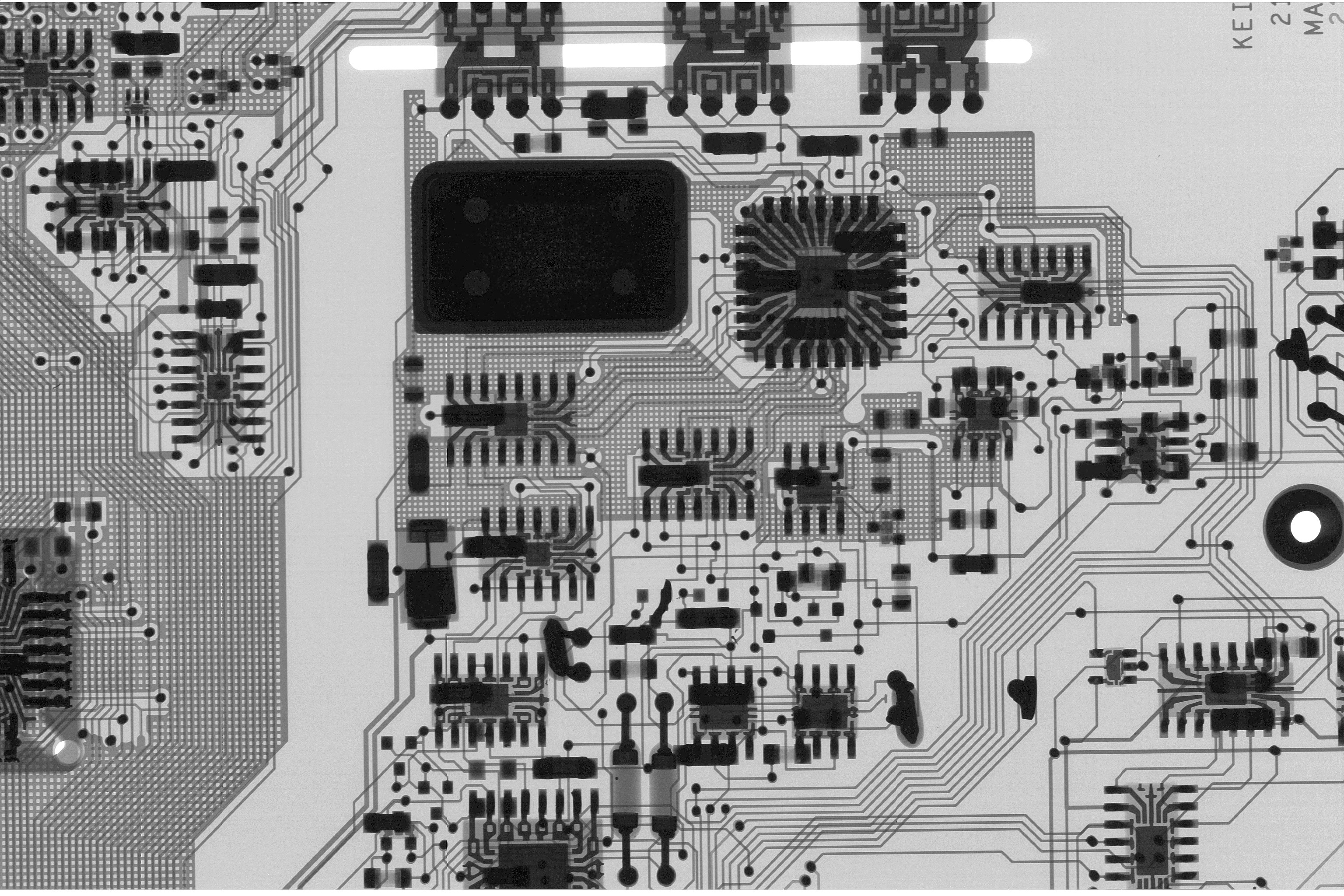

Various floating section from center of the board and linear power supply regulators

Low-noise front end amplifier with tilted board reveals better cross-section of the interconnect vias in this four layer circuit board.
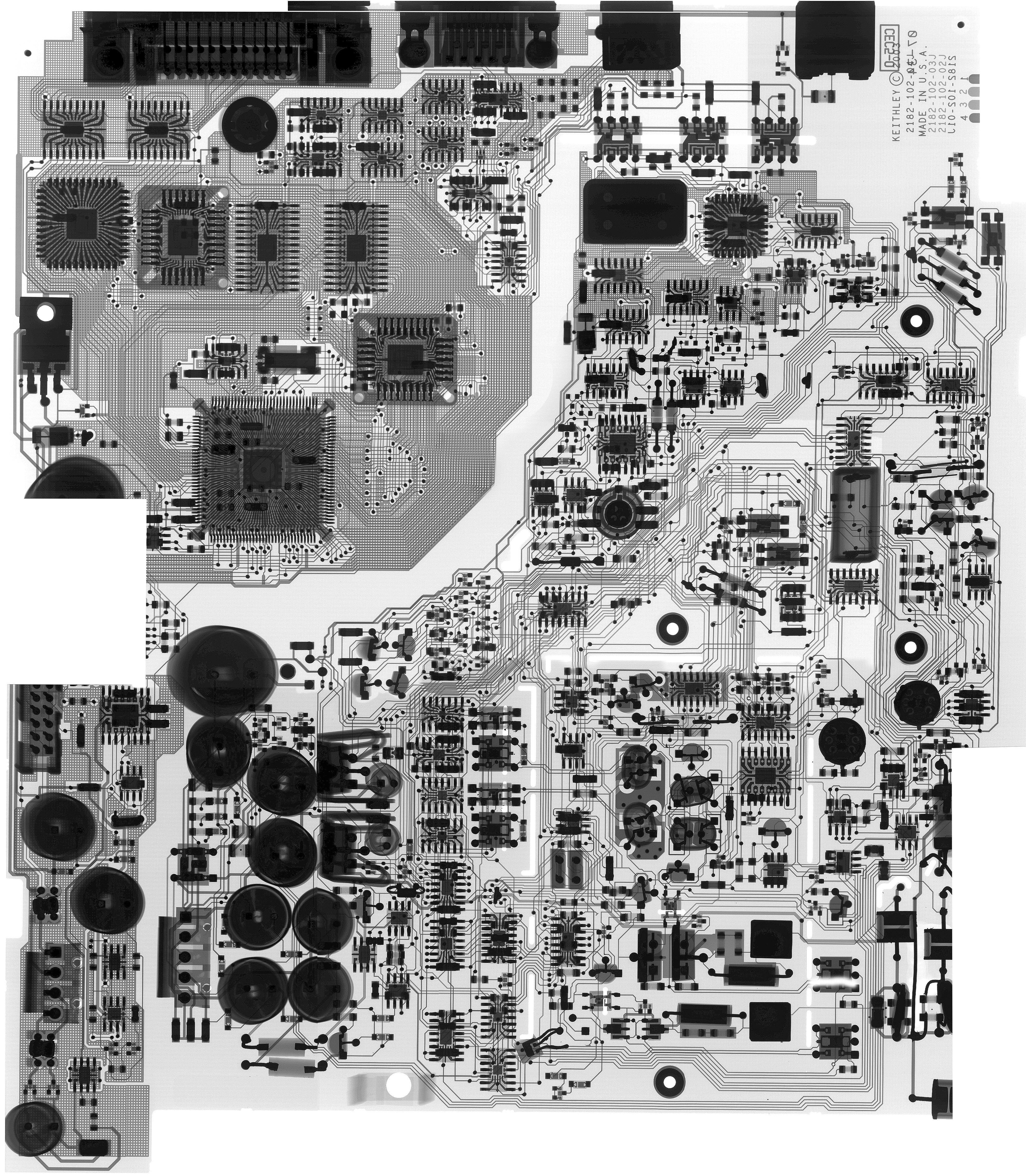
And final stitched overall board image of Keithley 2182A mainboard:
And magnified stitched pano of LNA section of the board:
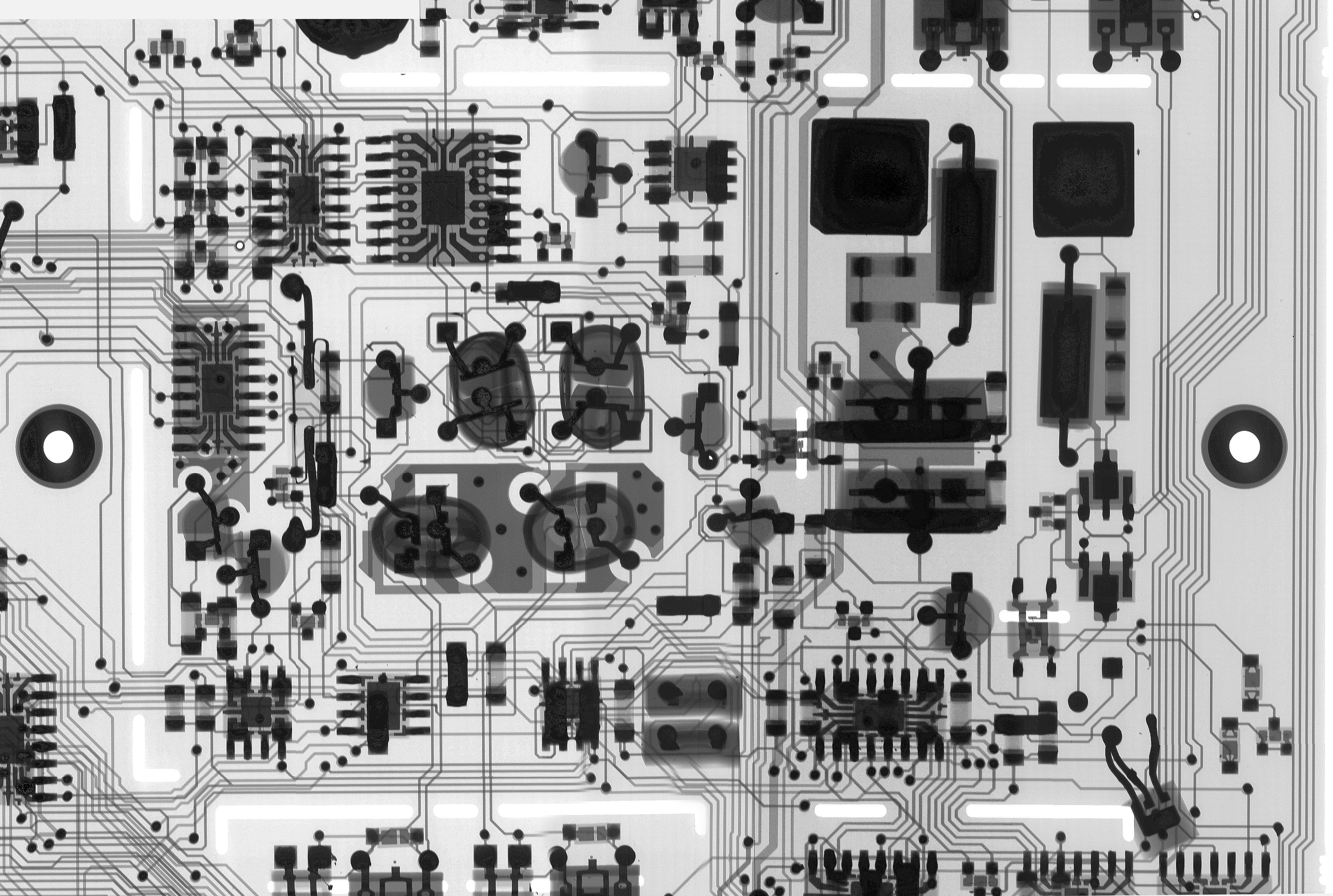
Hopefully this might help someone in repairs and learning. Little animation of LNA section is also built with 2 second alternating overlay:
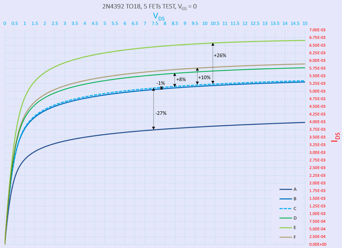
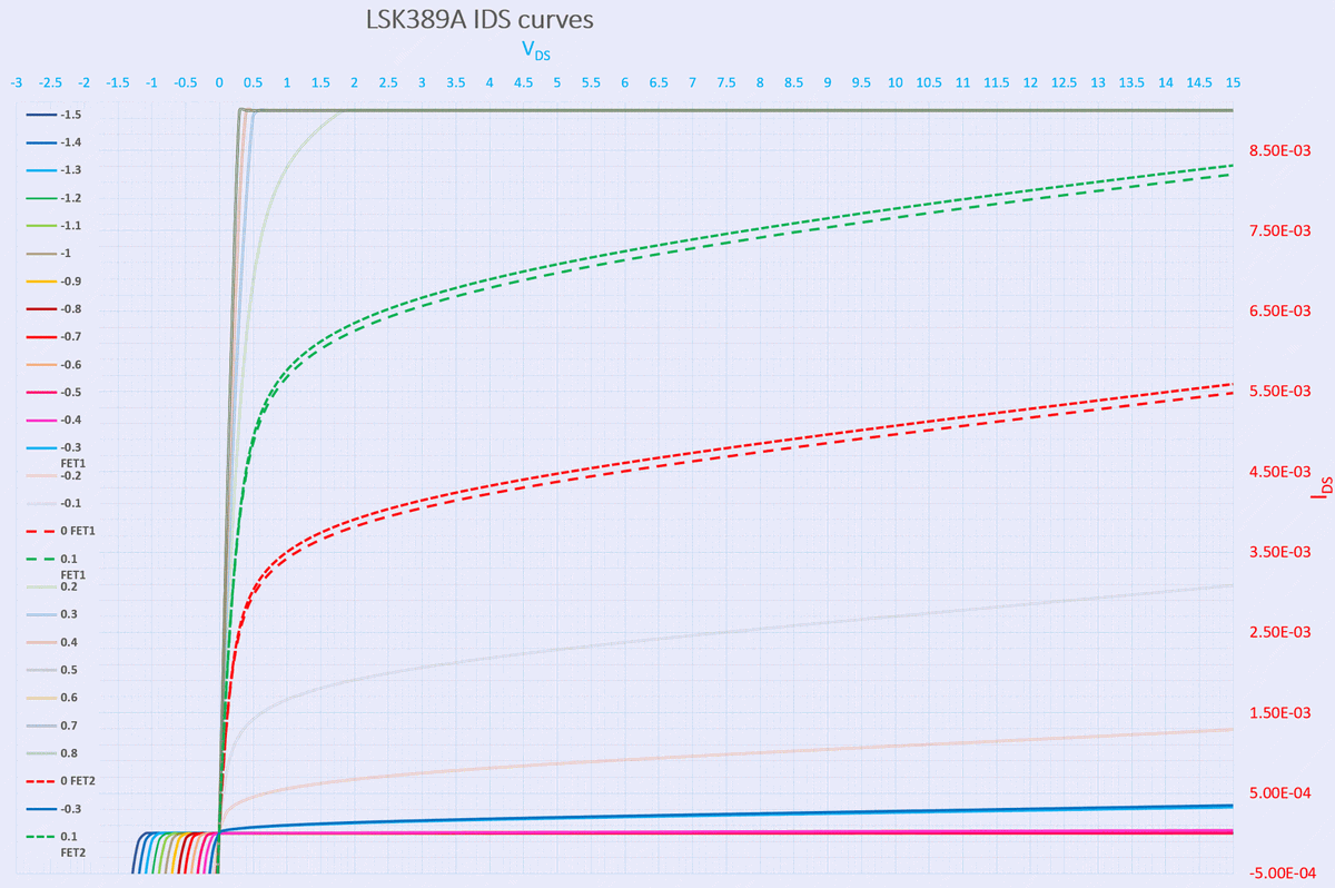
Transistor selection for LNA
Diagnostics
Other than traditional electrolytic capacitor replacement due to age, other issue with this meter was on channel 2. Channel was not reading correct values, and showing random charge pickup on any range for CH2. This was caused by bad optocoupler drive that control CH2 protection FETs. As result input was floating, and never connected to the LEMO connector.
Replacement of bad TLP591B optocoupler fixed the meter, and no other issues were found.
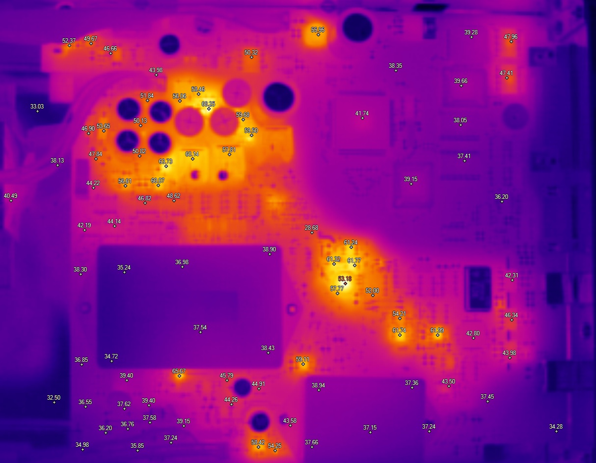
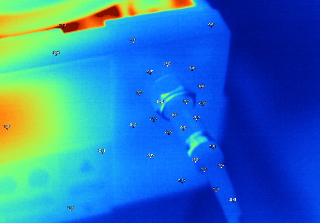
Thermal image captures
Firmware
Model 2182 (NOT COMPATIBLE WITH 2182*A*).
Firmware ROM dumps from two ROMs, read by general purpose ROM programmer.
| Firmware version | Combined binary | ODD ROM | EVEN ROM | Motorola SREC | Release notes |
|---|---|---|---|---|---|
| Model 2182 A07, V.54.1, Mar 8 12:18:37 EST 2000 | 2182-803-A07 CHK:00E69901 | 2182-804-A07 CHK:009A88AB |
Model 2182*A* (NOT COMPATIBLE WITH 2182 non-A).
| Firmware version | Combined binary | ODD ROM | EVEN ROM | Motorola SREC | Release notes | |
|---|---|---|---|---|---|---|
| Model 2182A, C02, Version 103.1, Aug 10 13:58:16 EDT 2007 | 2182A-803-C07 | |||||
| Model 2182A, C06, Version 109.2, Nov 5 09:23:44 EST 2012 | 2182A-803-C07 | |||||
| Model 2182A, C07, Version 109.2, Nov 5 09:23:44 EST 2012 | 2182A-803-C07 Binary | 2182A-803-C07 |
Model 2182A supports field upgrade using Keithley’s Flash Wizard tool. Version C12 of it available here.
Other possible issues
Overload at the input not always break parts, but may instead cause sensitive input stage degradation, and that would result in excessive noise readings. Noise testing should be a part of test procedure and verification, to ensure meter correct operation. It is important to take protective measures to avoid nanovolt-meter input overload. Our article about 2182A repair shows what can happen when high-energy high-voltage signal applied at the instrument input.
Tweaks and tricks
Autozero functionality.
Watch out for Autozero mode, if the measurement rate changed to different NPLC settings, meter will automatically turn the autozero function on. If this is unwanted (for example in pulse high-speed measurement system), make sure you have correct autozero setting after NPLC configuration.
Calibration
Thanks to autocalibration function, Keithley 2182 need reduced set of artifact external signals to be fully calibrated. Only zero volt low-thermal short and 10.000000 V DC voltage reference are required to perform full calibration. Low-level service calibration also need additional 1.000000V DC voltage reference.
Catch is in details, for best accuracy K2182 expects exact voltages to be used for calibration, so low-noise high-stability source is required. Recommended source is Fluke 5700A calibrator, but likely Fluke 55xx series or Datron/Wavetek calibrators would work just as good. If unknown or uncalibrated source is used, then using reference multimeter, such as Keysight 3458A can help to maintain low uncertainty.
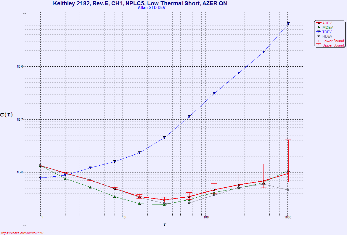
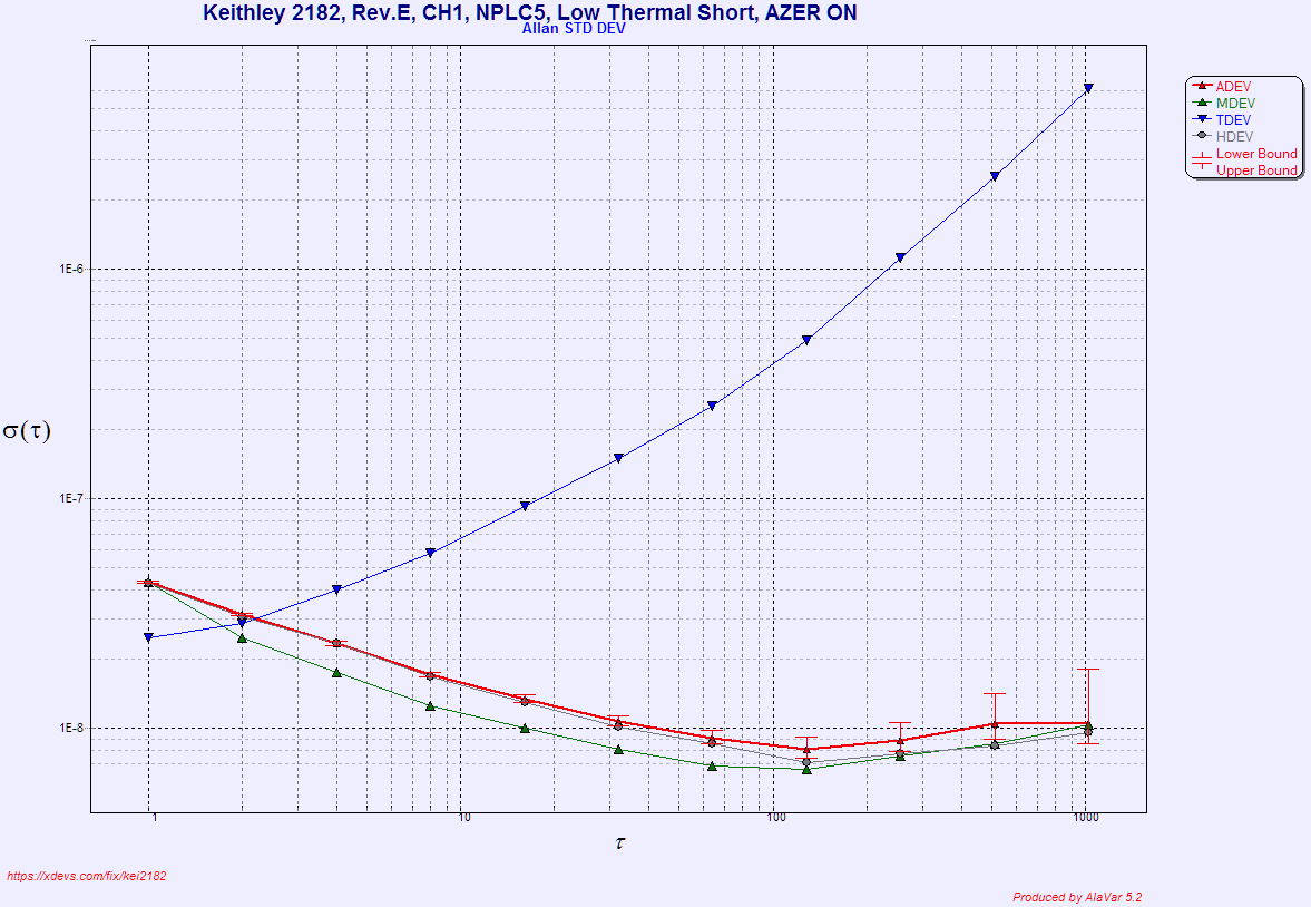
Performance verification
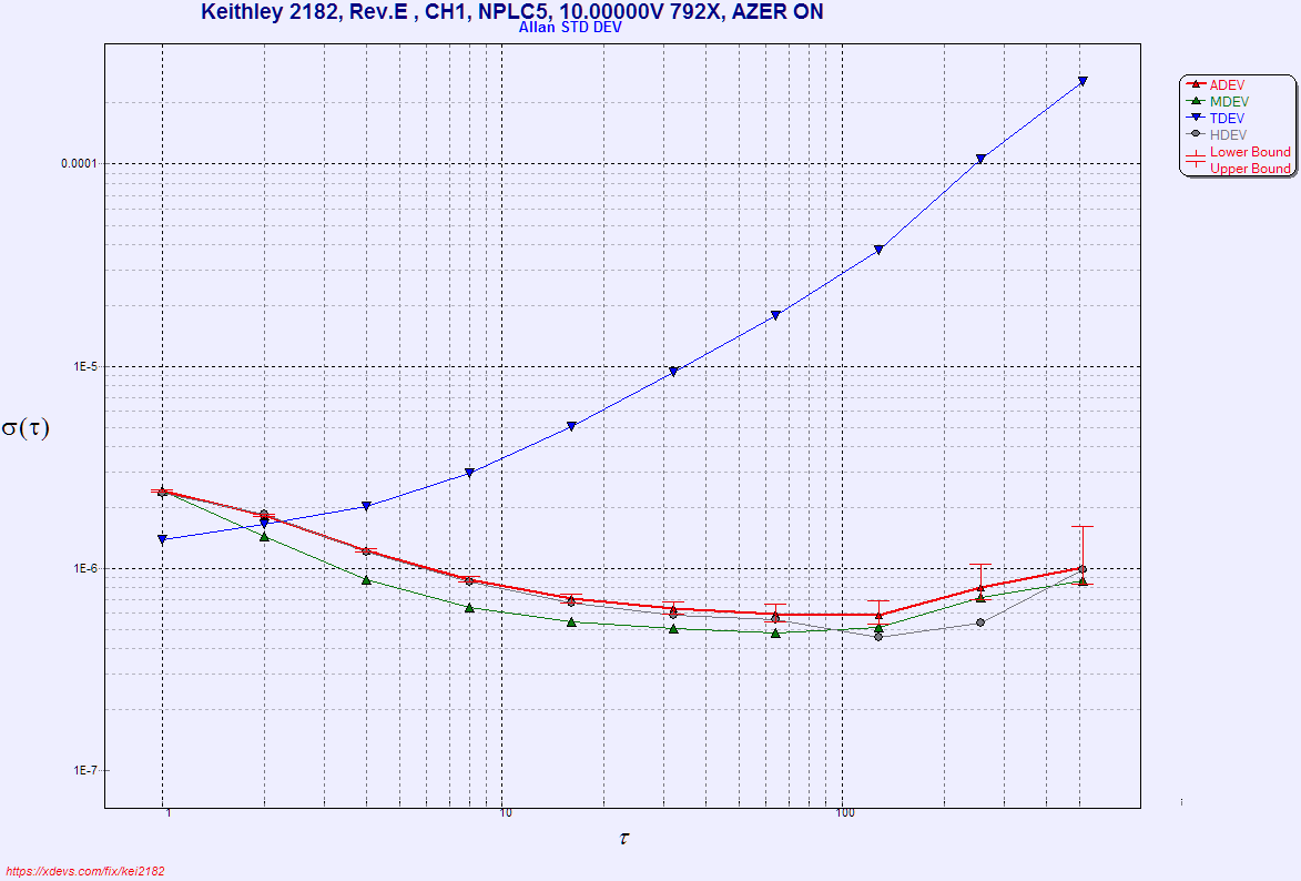
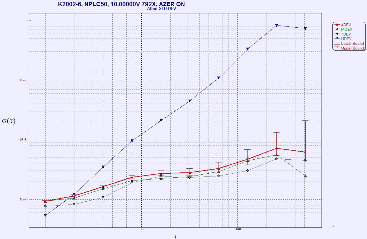
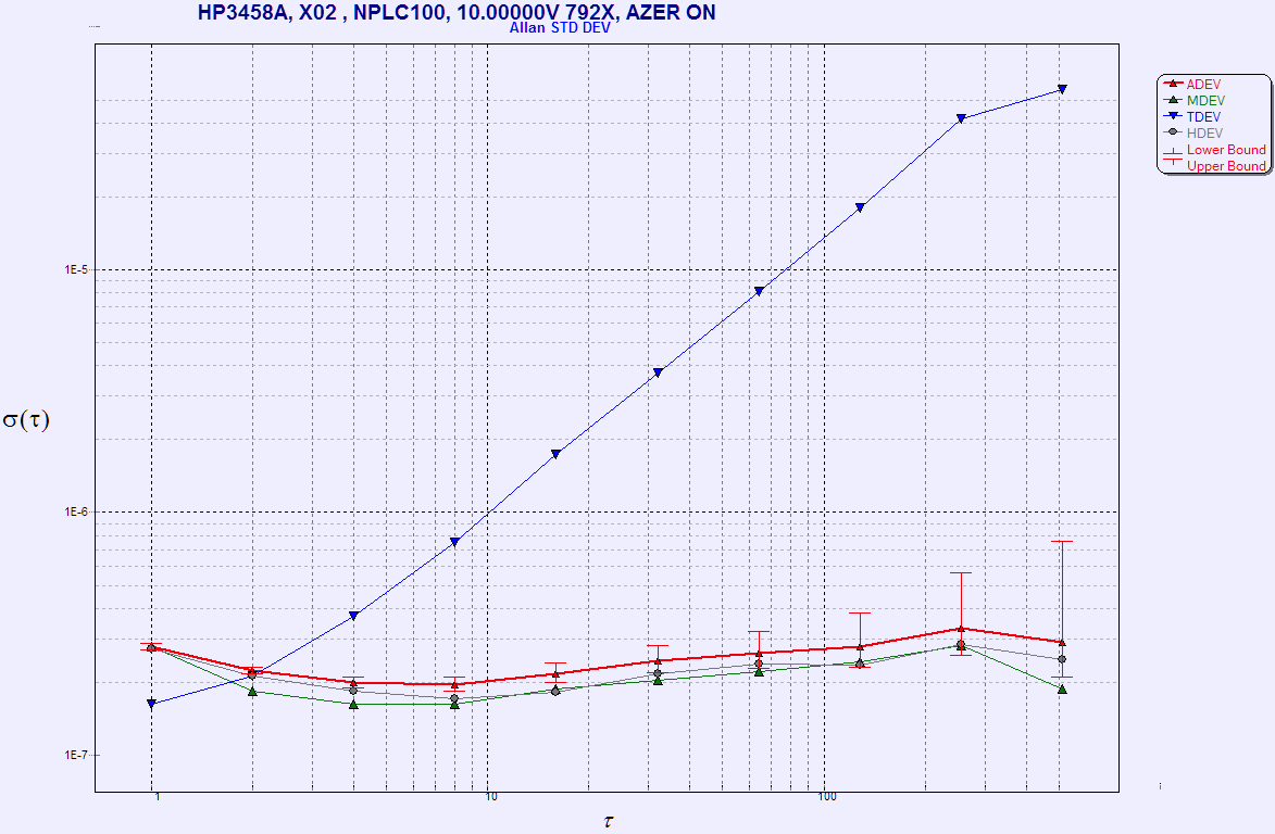
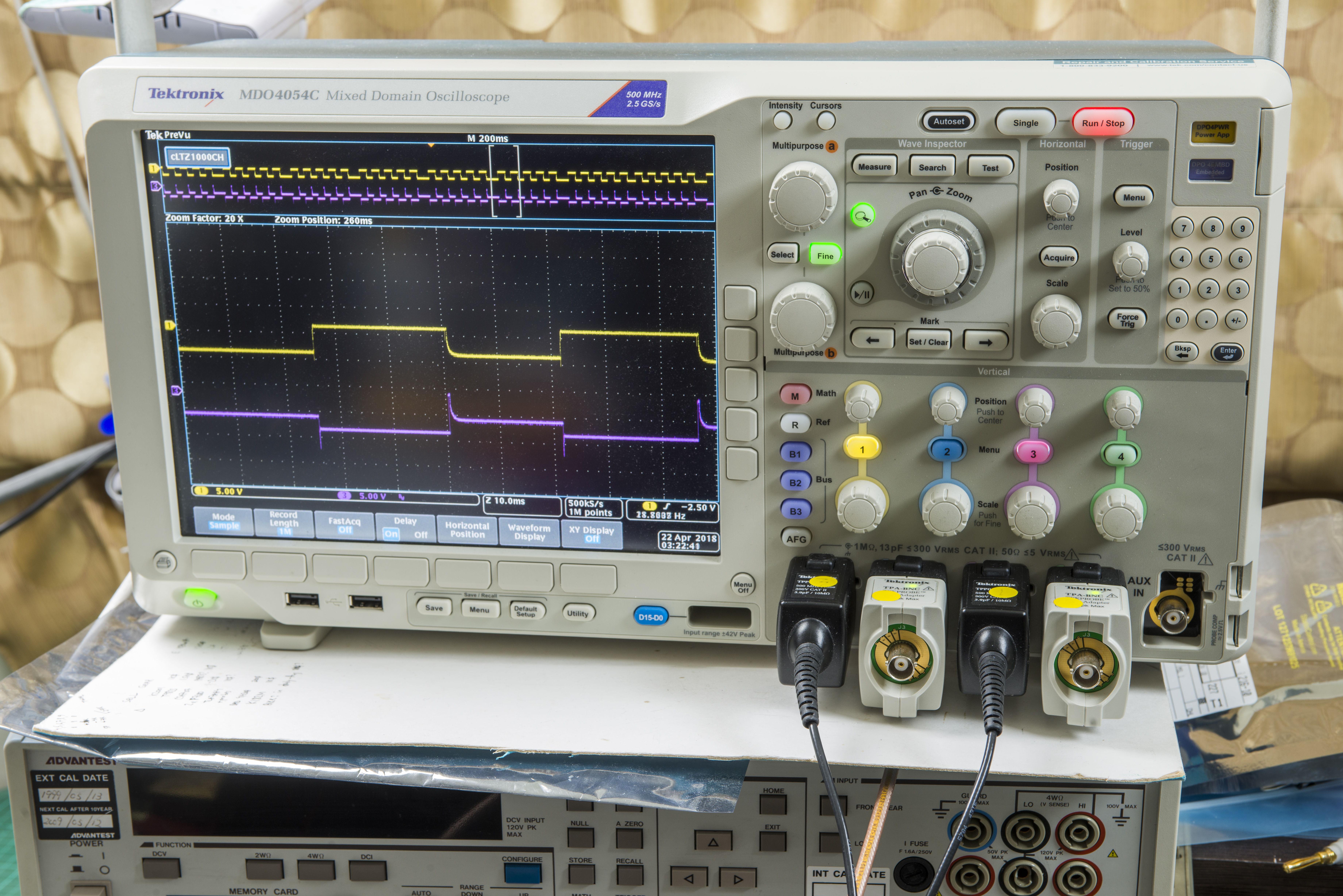
DCV Noise evaluation at shorted inputs
Restoration summary
Cost involved in this project:
| Item | Cost | Shipping | Supplier |
|---|---|---|---|
| Keithley 2182 unit | $xxx | N/A | Internal |
| Dead Keithley 2182A | $400 | 30$ | Friend :) |
| LEMO copper-only FVN.1S and EVP.1S connectors | $1260 | 30$ | LEMO |
| 30 pcs CHV2010-FX-1005ELFCT-ND Resistors 10 MΩ 2010 size | $10 | 0$ | Digikey USA |
This article would be impossible without work of Todd and his Model 2182 and his content and testing results. We also would like to give credits to pipelie, who helped a lot to push xDevs.com project forward. Thank you!
It’s a joy for any passionate engineer to see these instruments working, despite all those years. They might not be new and fancy with touchscreen TFTs, but still hard to replace when one need the accurate low-level measurement.
If you do have any questions, jump in comments! All the feedback is appreciated-
Projects like this are born from passion and a desire to share how things work. Education is the foundation of a healthy society - especially important in today's volatile world. xDevs began as a personal project notepad in Kherson, Ukraine back in 2008 and has grown with support of passionate readers just like you. There are no (and never will be) any ads, sponsors or shareholders behind xDevs.com, just a commitment to inspire and help learning. If you are in a position to help others like us, please consider supporting xDevs.com’s home-country Ukraine in its defense of freedom to speak, freedom to live in peace and freedom to choose their way. You can use official site to support Ukraine – United24 or Help99. Every cent counts.
Modified: July 18, 2026, 3:40 p.m.