- New “MEGA” TEC chamber, revision 2021
- First test with small 40W TEC in empty chamber
- Initial tests of the DC Voltage temperature coefficient with different DMMs
- Temperature coefficient measurement for ESI SR104 10000 Ω standard
Previous TEC chamber designs
Over last 6 years multiple small size insulated thermal chambers were build at xDevs. Peltier heat pump was used as active element to provide both cooling and heating capability.
Previous design from 2018-2020 years successfully used for various LTZ1000A voltage reference and small resistance (such as Fluke 742A) standards temperature tests. It was using 40W single-stage TEC element, closed-loop watercooling pump+HX and copper heatsink as thermal exchanger.

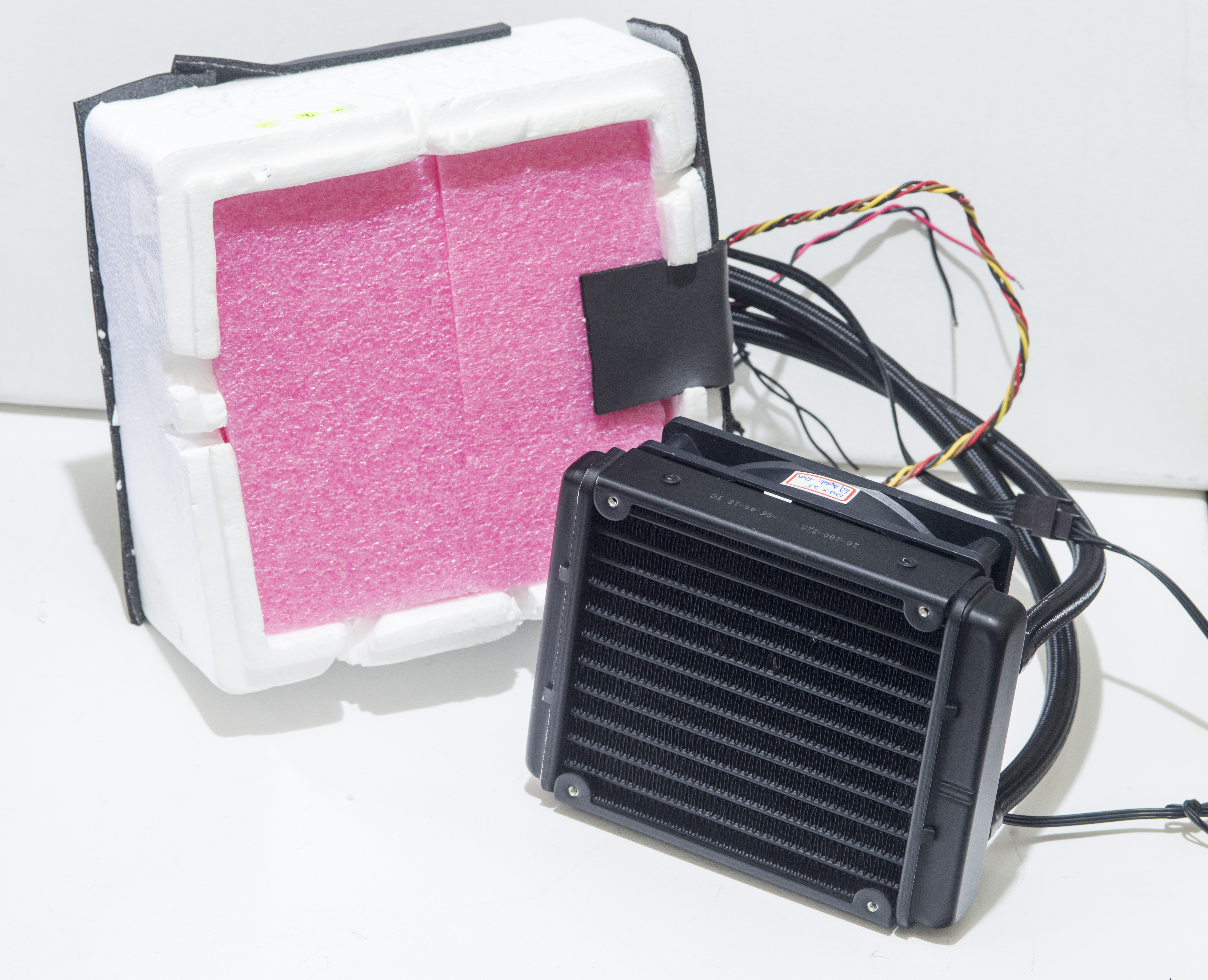
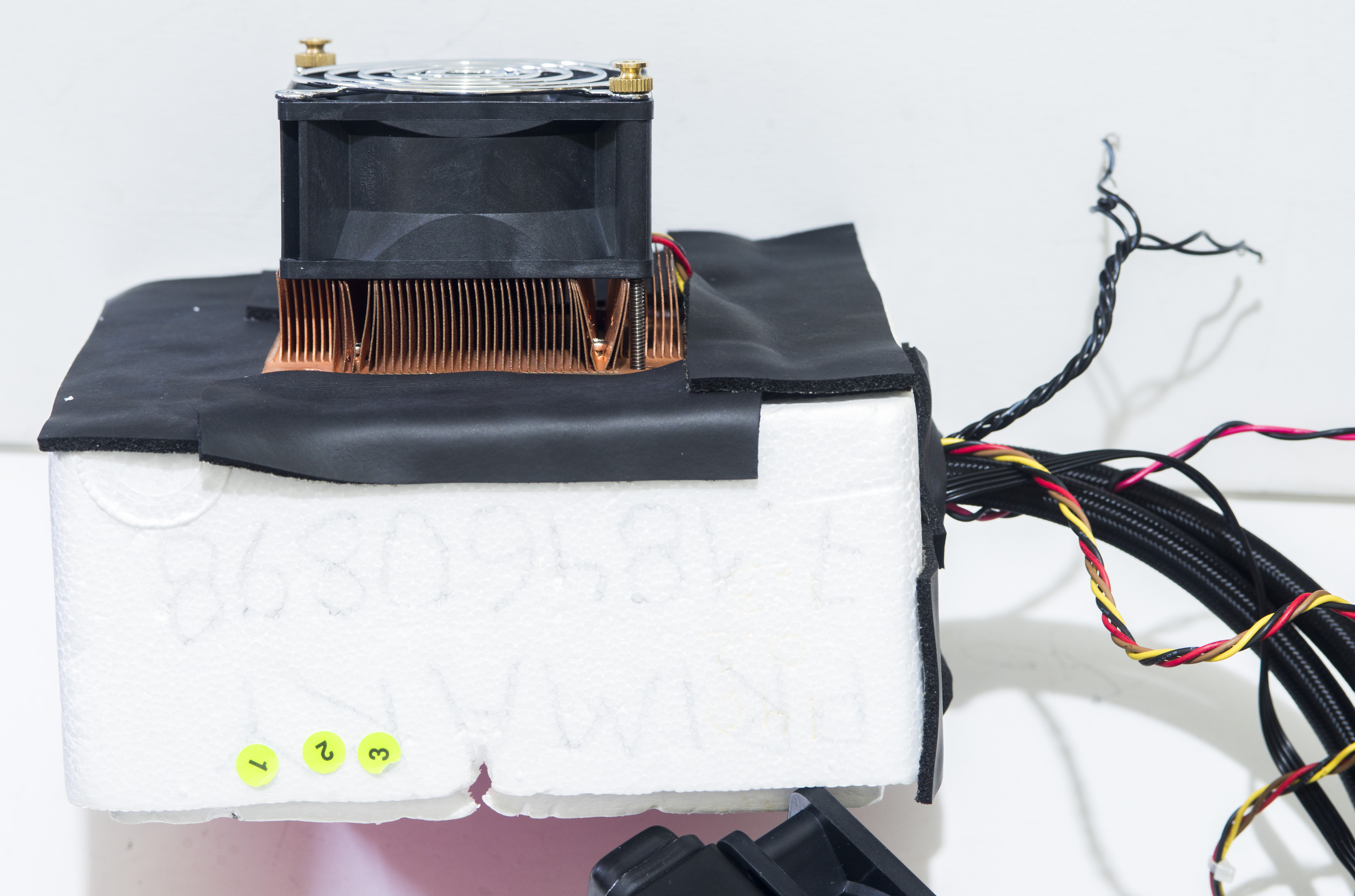
80×80×32 mm fan installed on thermal chamber to actively mix air within insulated chamber. This helped to obtain uniformity better than 0.2 °C when passive or <5W active devices are used in chamber as DUT.
Components layout in the larger Styrofoam box for better thermal ambient insulation shown on photos below.
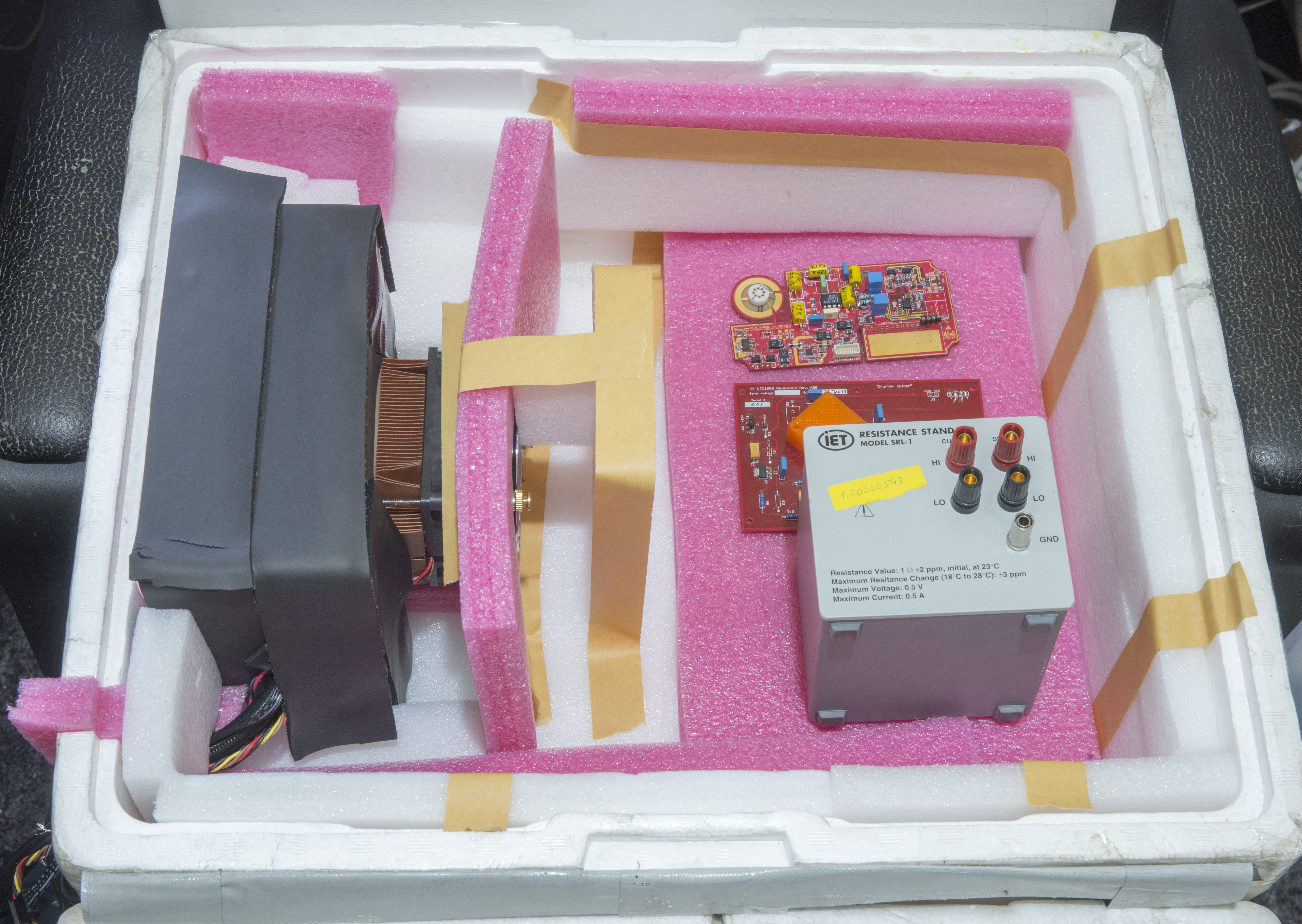
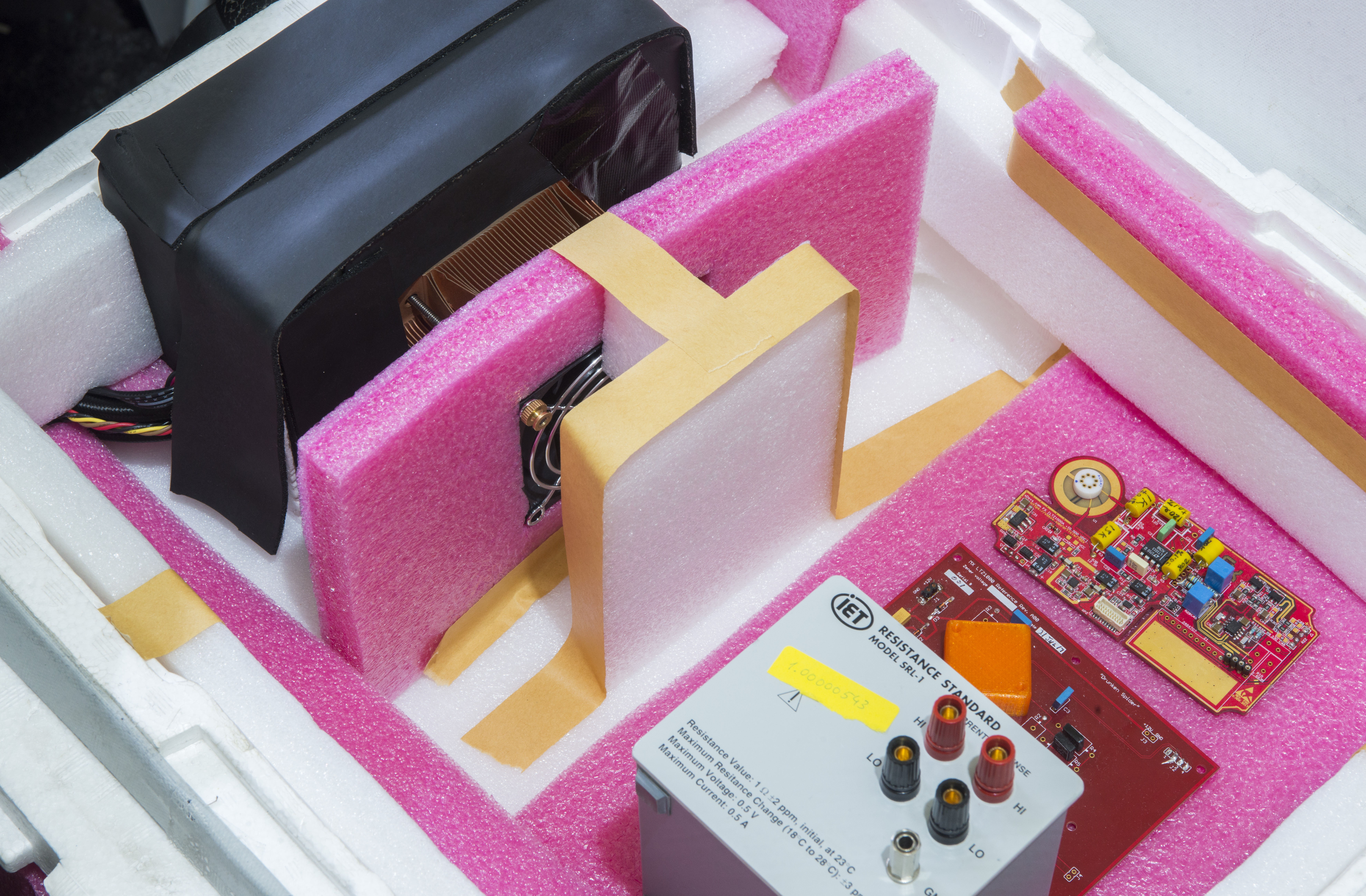
Device under test examples, such as Wavetek 7000 DC voltage reference and Keithley 262 + EM A10 nanovolt amplifier were tested using this chamber.


New “MEGA” TEC chamber, revision 2021
But I always wanted to have ability of testing larger devices, such as full size 19” DMM (Keysight 3458A, Fluke 8508A and alike). Ideally chamber should also support even bigger and heavier devices, such as multi-function calibrator Fluke 5720A or Datron 4808.
However testing such active instruments is not practical or possible with low power 40W Peltier TEC. This is problem for next monster chamber project aimed to solve.
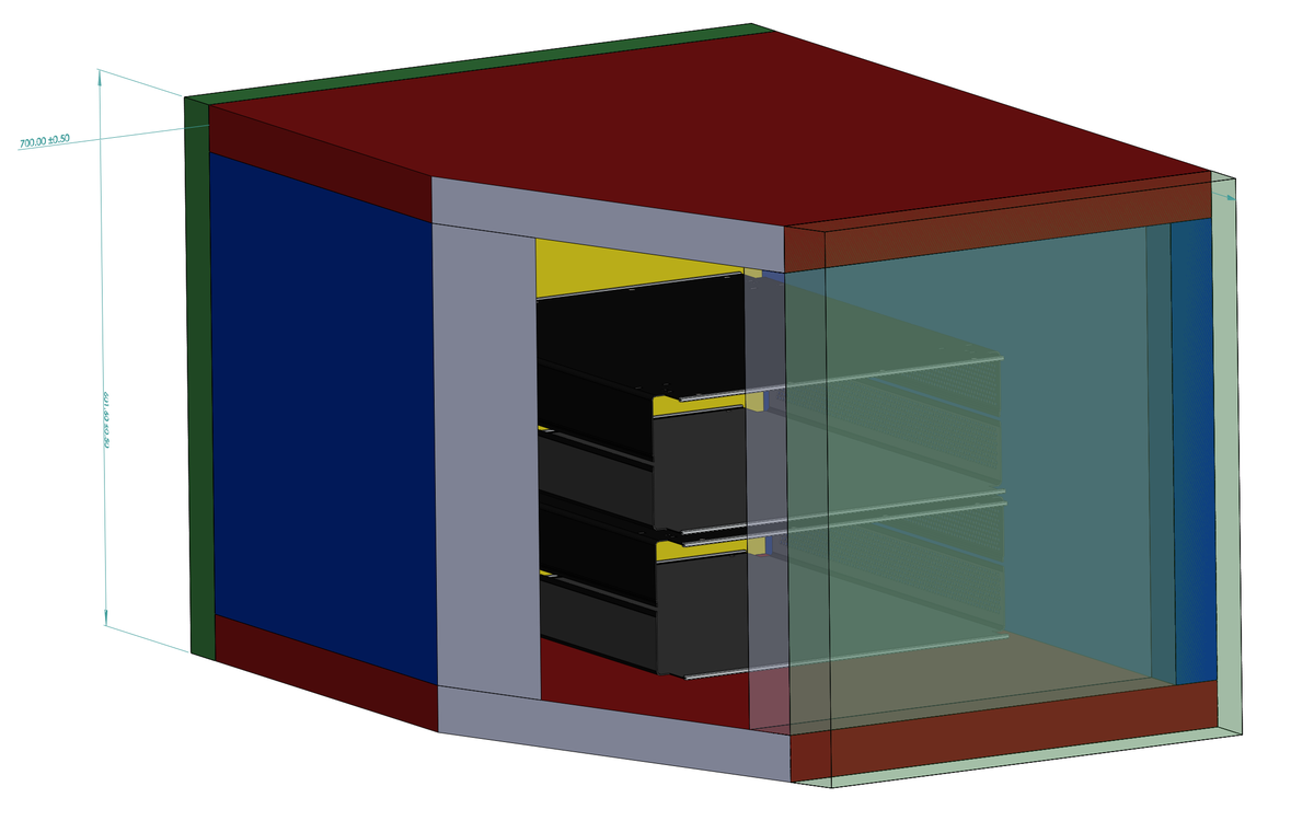
After checking available space on bench and targeted use cases next feature set was established as target:
- Big enough to fit 5720A+5725A and 3458A or multiple 732A
- 850 × 600 × 500 mm inner volume
- High power TEC module assembly to allow fast control, to support max 900W active load inside chamber
- Desired temperature range from 0 °C to +60 °C
- Temperature uniformity better than 0.1 °C
- Temperature stability better than 0.05 °C with heat load <50 W
- Temperature stability better than 0.1 °C with heat load 500 W
- Watercooling loop for TECs to allow uniform 50-100mm isolation from ambient
- Ambient influence less than 0.01 °C/°C
- Possibility for humidity control?
- Possibility for pressure control?
- Easy removable front door\lid to allow DUT management
- Material BOM cost less than $500 USD
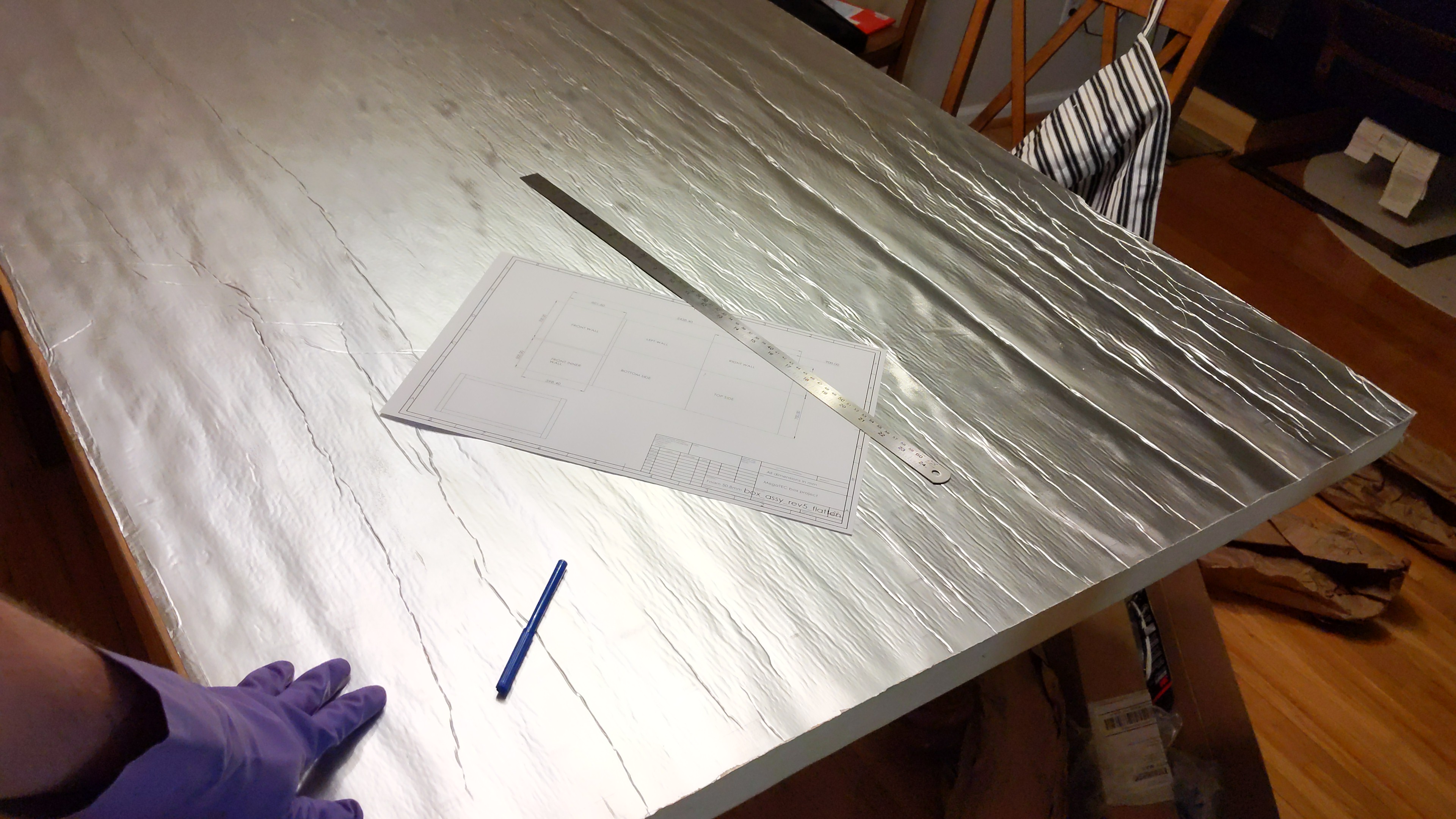
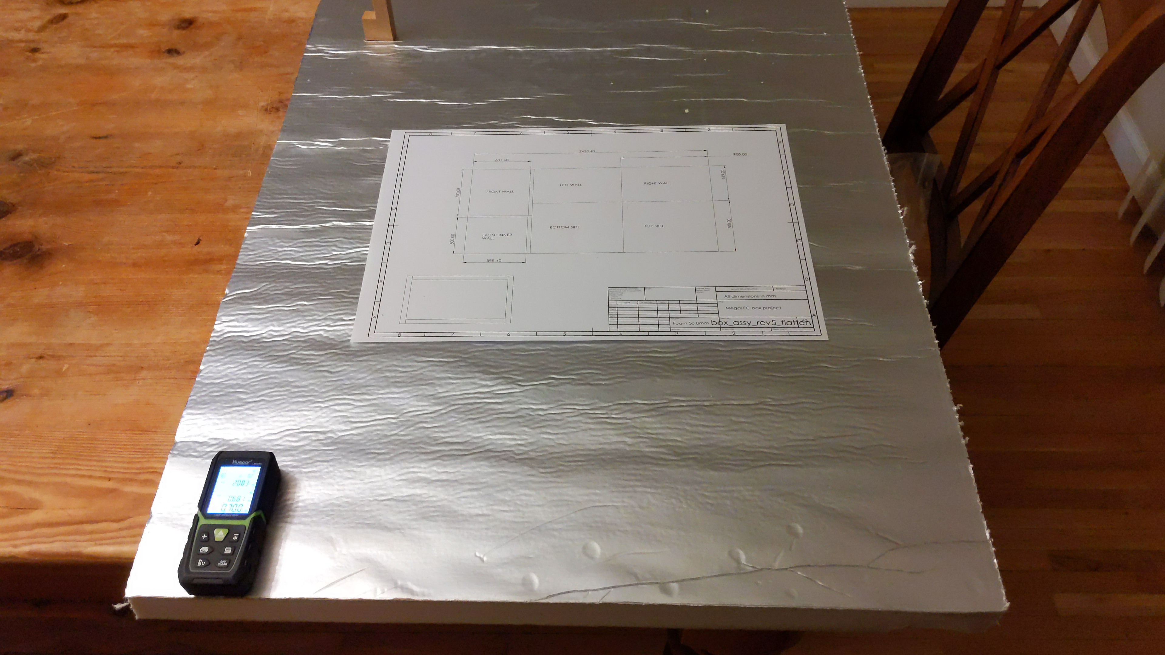
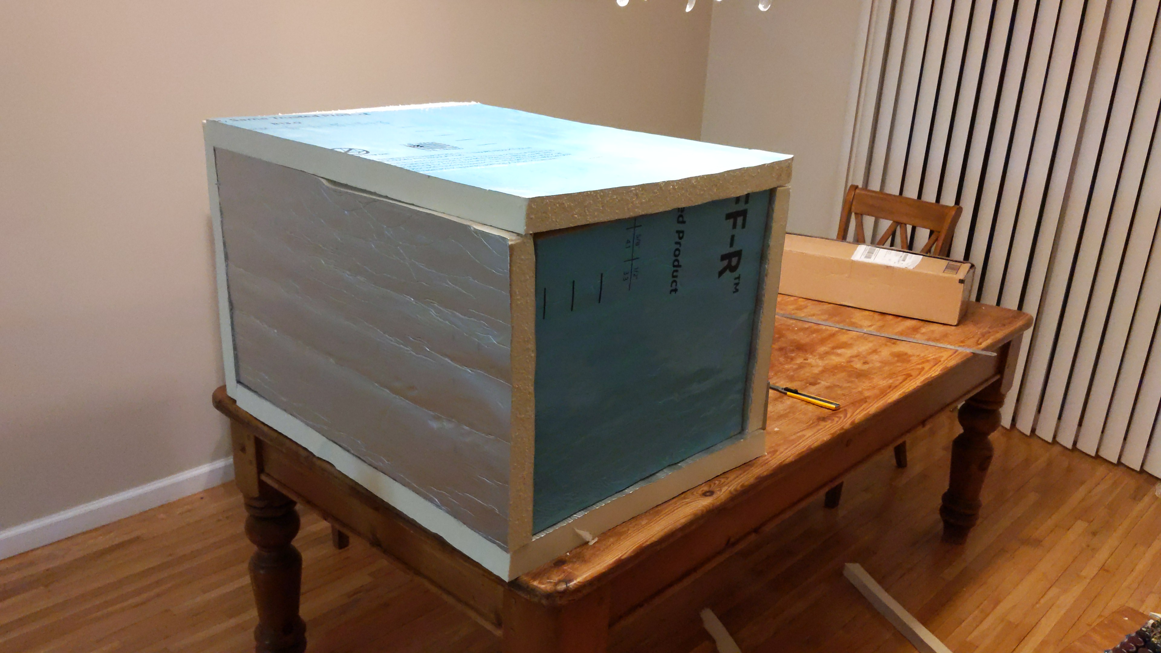
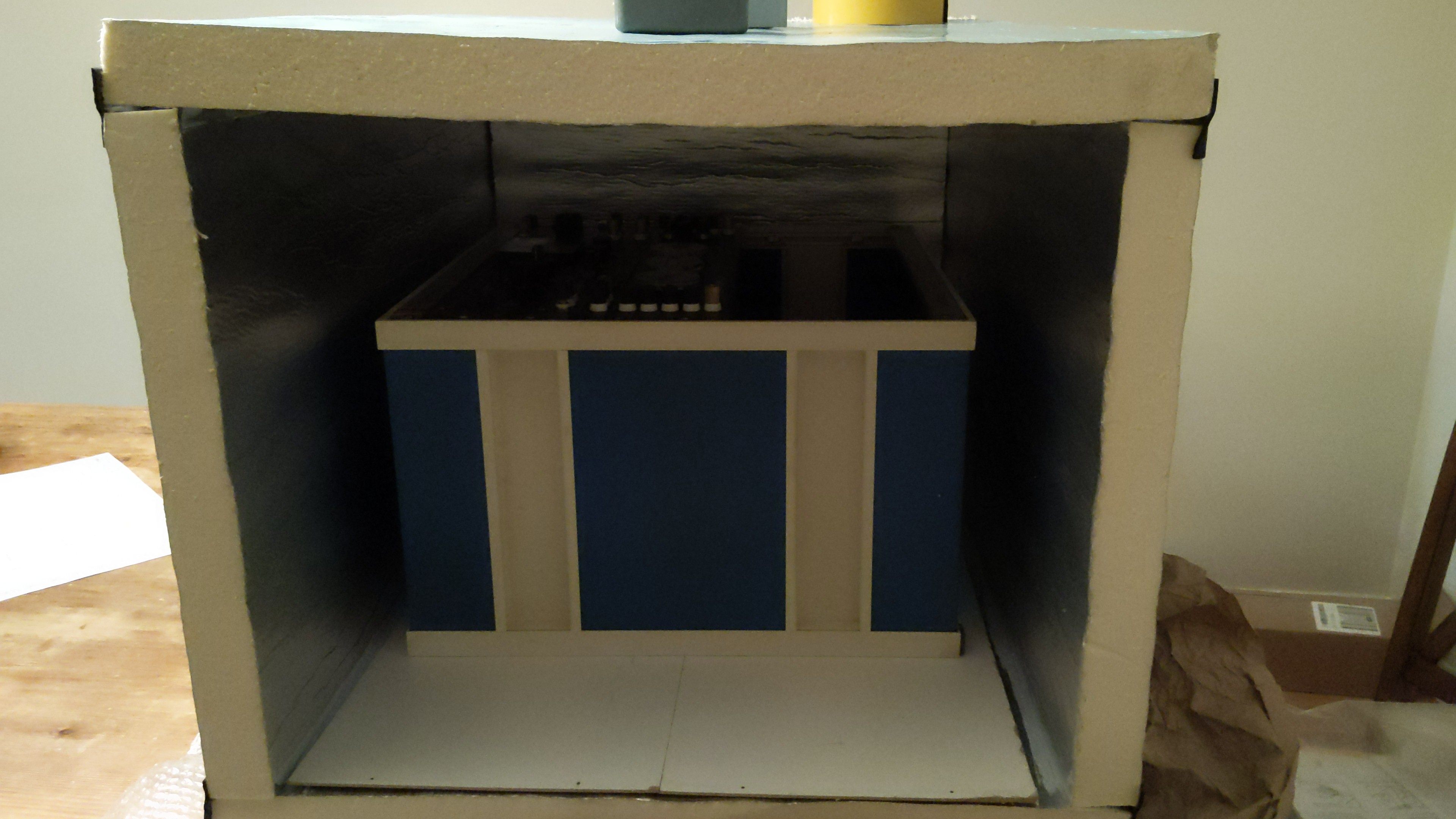
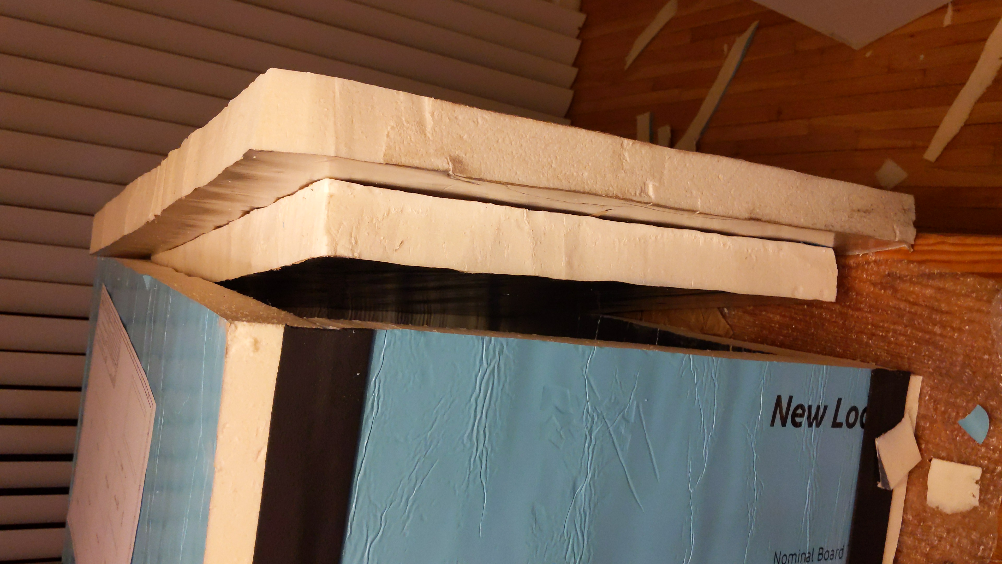
Dow Super TUFF-R R-13 foam faced board was used as a starting point to provide robust thermal insulation. Two sheets were acquired from local Home Depot store
Simple CAD was sketched together with dimensions in mind to fit all parts on a 1.25 sheets.
How let’s cut board to pieces and start layout
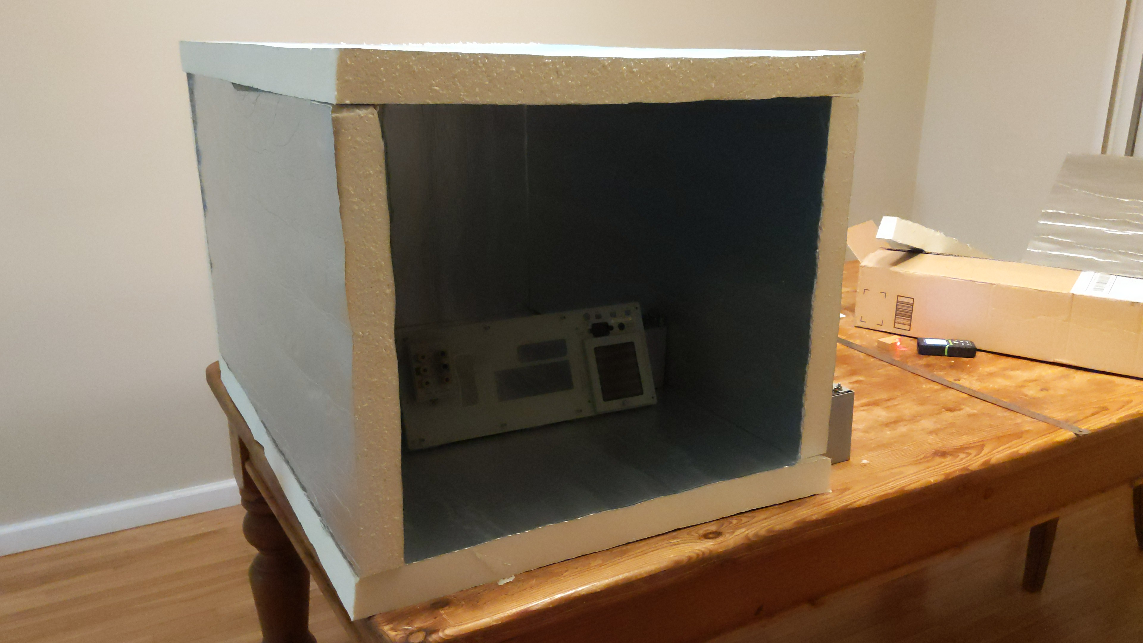

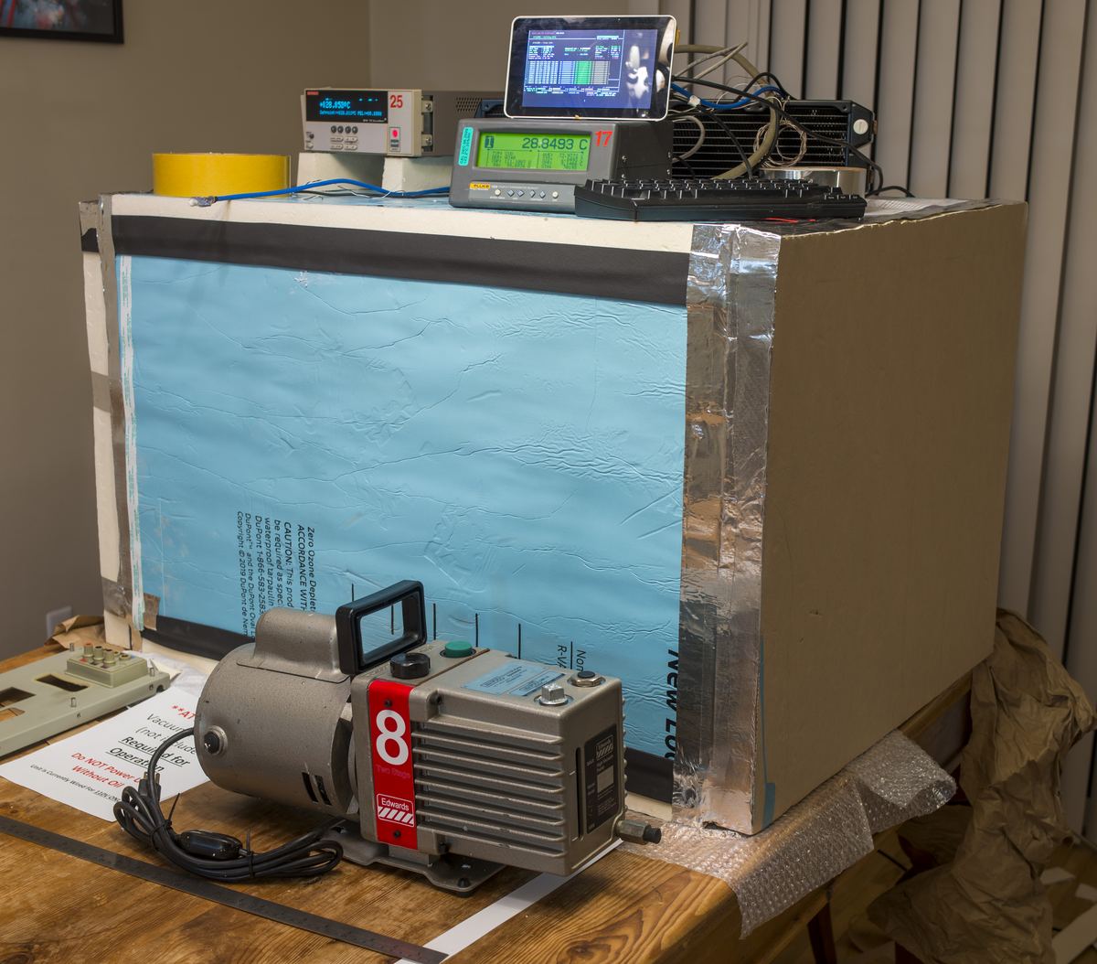
We can use random 8½-digit DMM (Advantest R6581T) to demonstrate available room in chamber.
Even bigger devices, such as ESI 242D resistance system could fit in chamber. Sideways only :)
However main goal to fit 5720A+5725A+3458A is met.
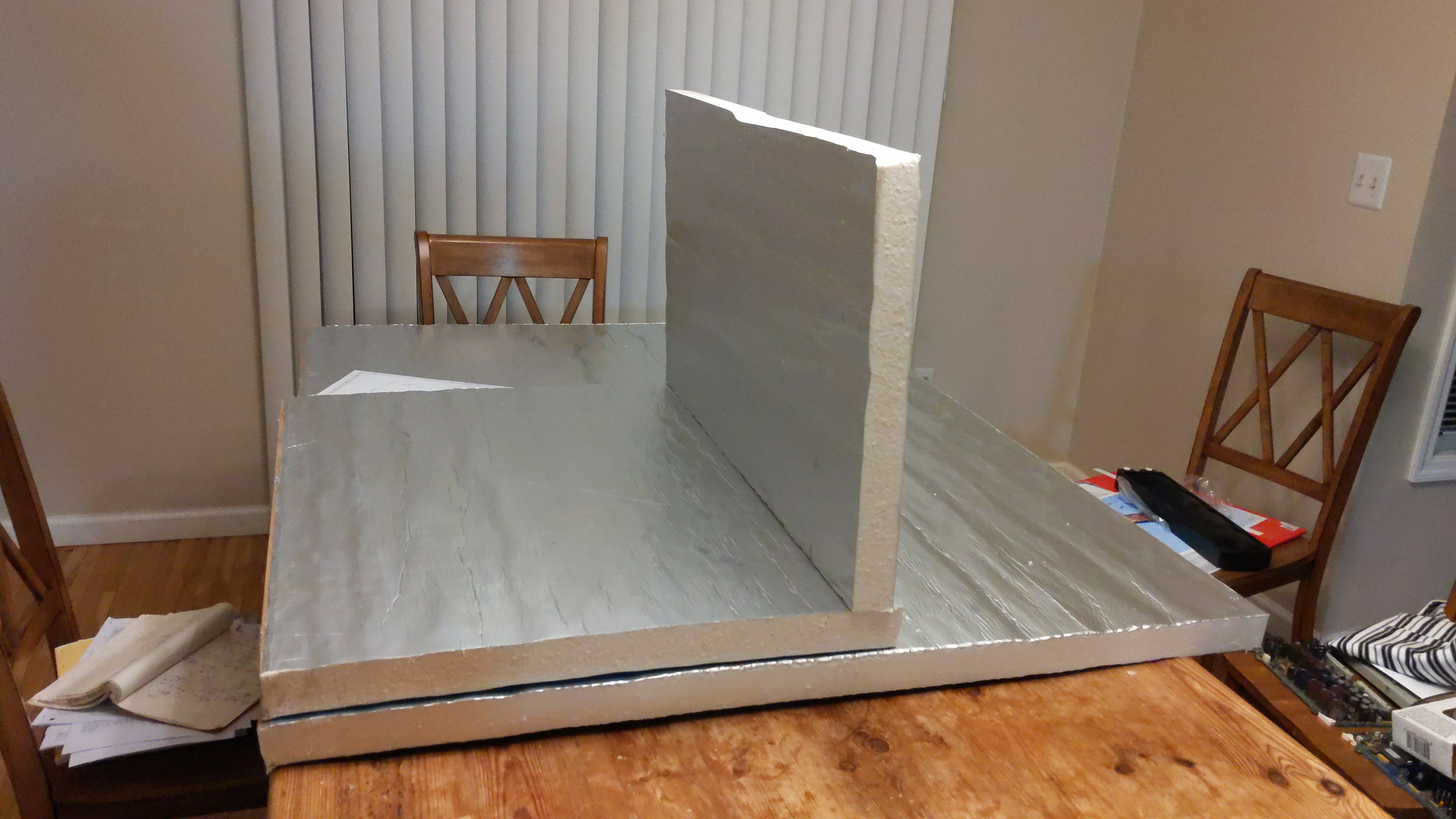
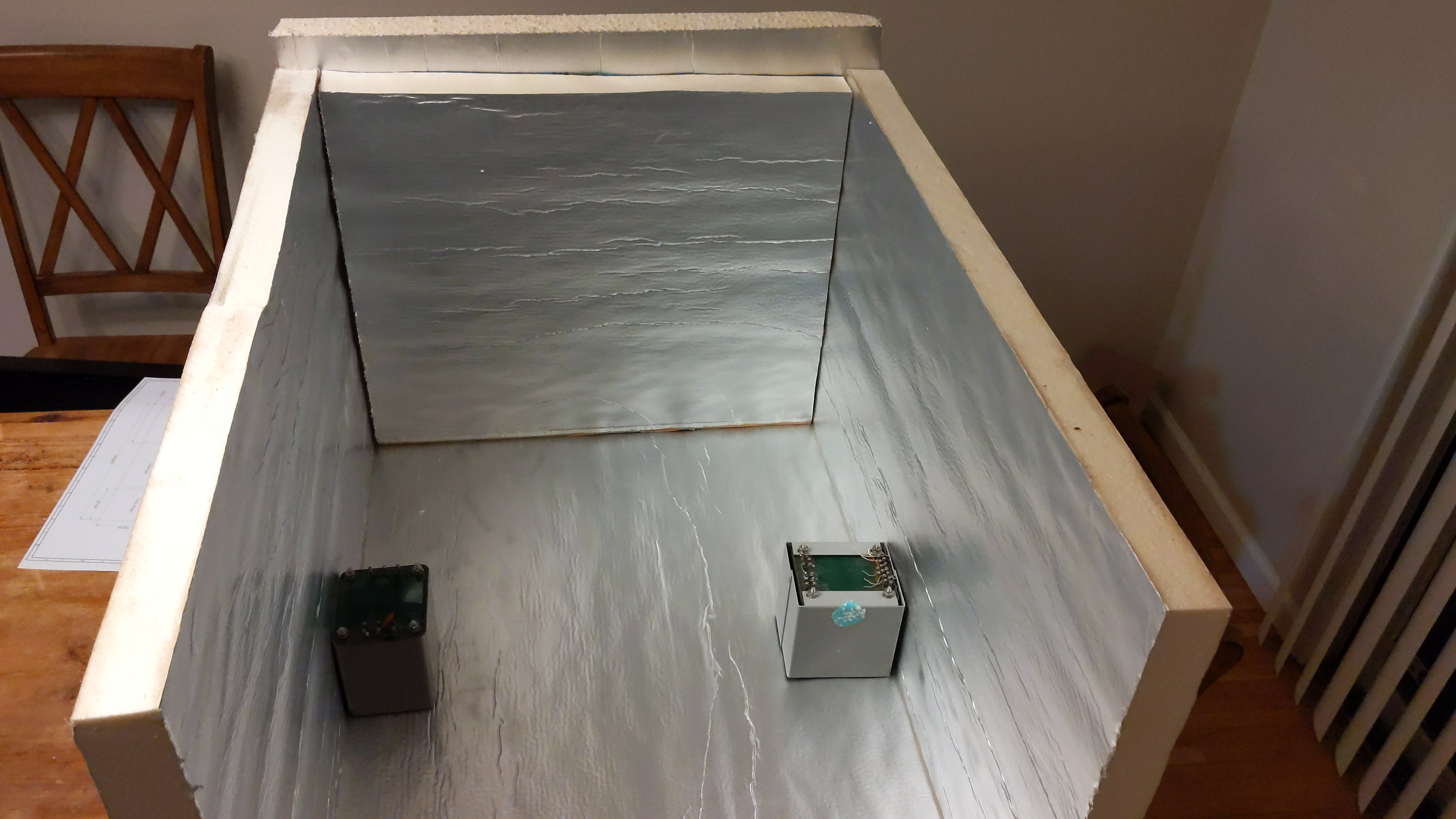
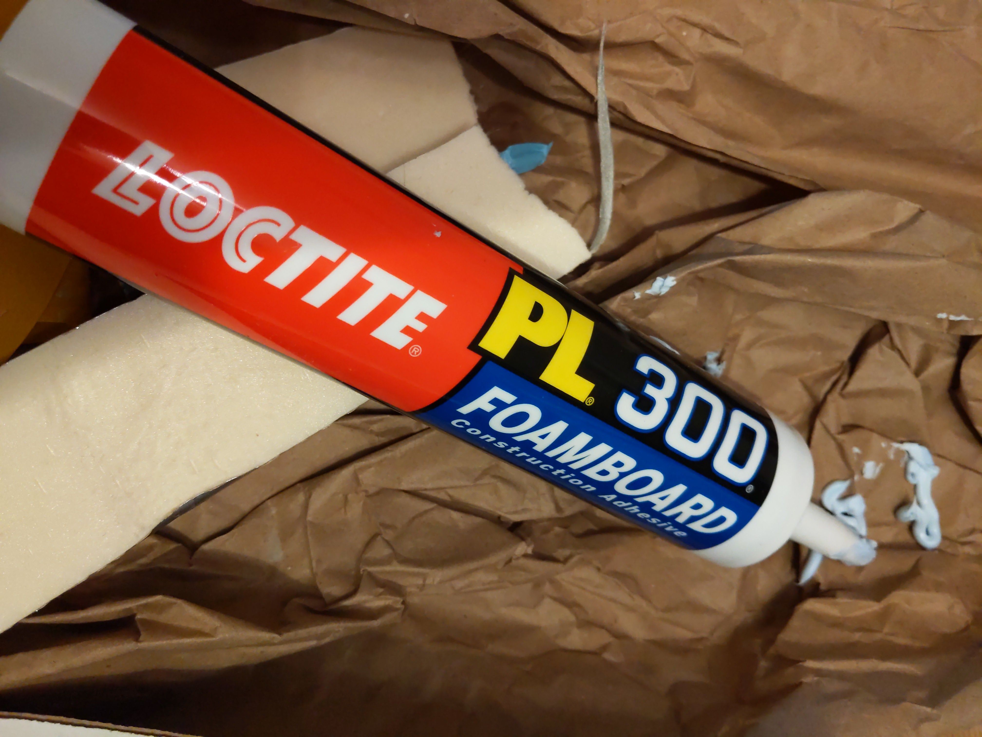
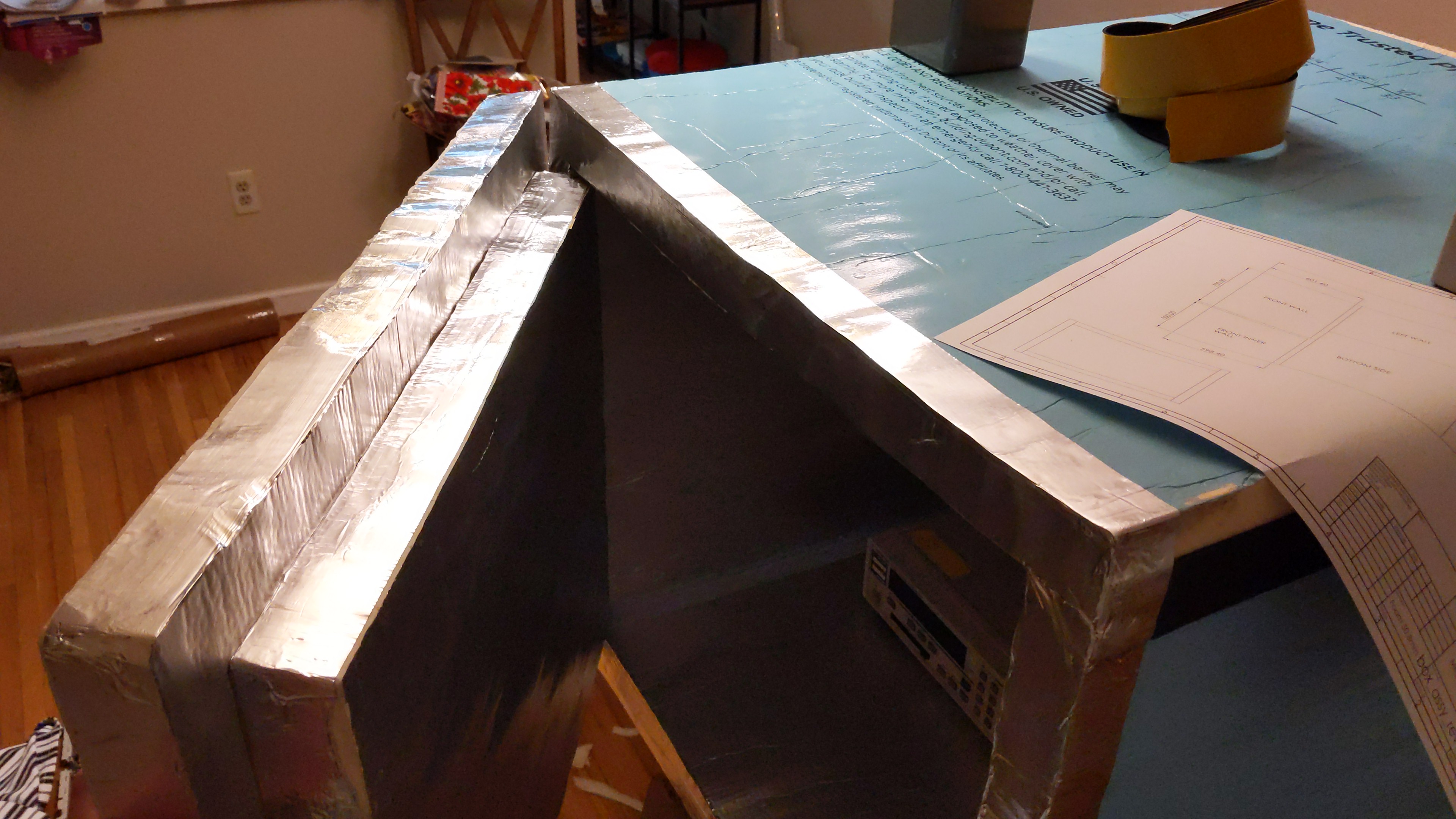
Looking pretty good, time to glue the edges on all walls and attach them to base sheet. Special Loctite PL300 latex-based foam-board glue was used to ensure good adhesion to foam wall. Full curing time of this glue is 7 days.
It is designed to be operated in temperature range from -17.7 to +77 °C. This is good enough for our design target.
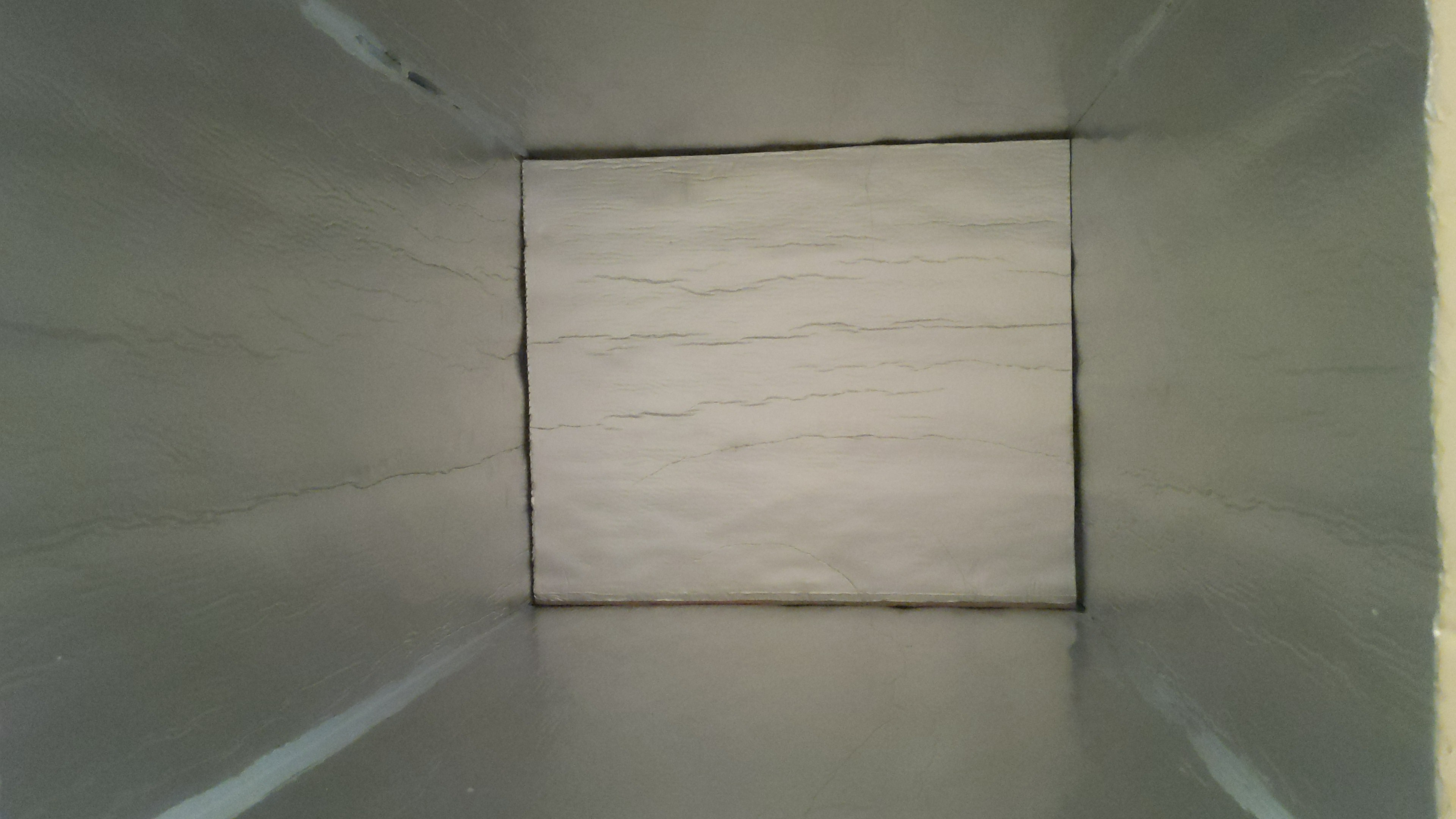

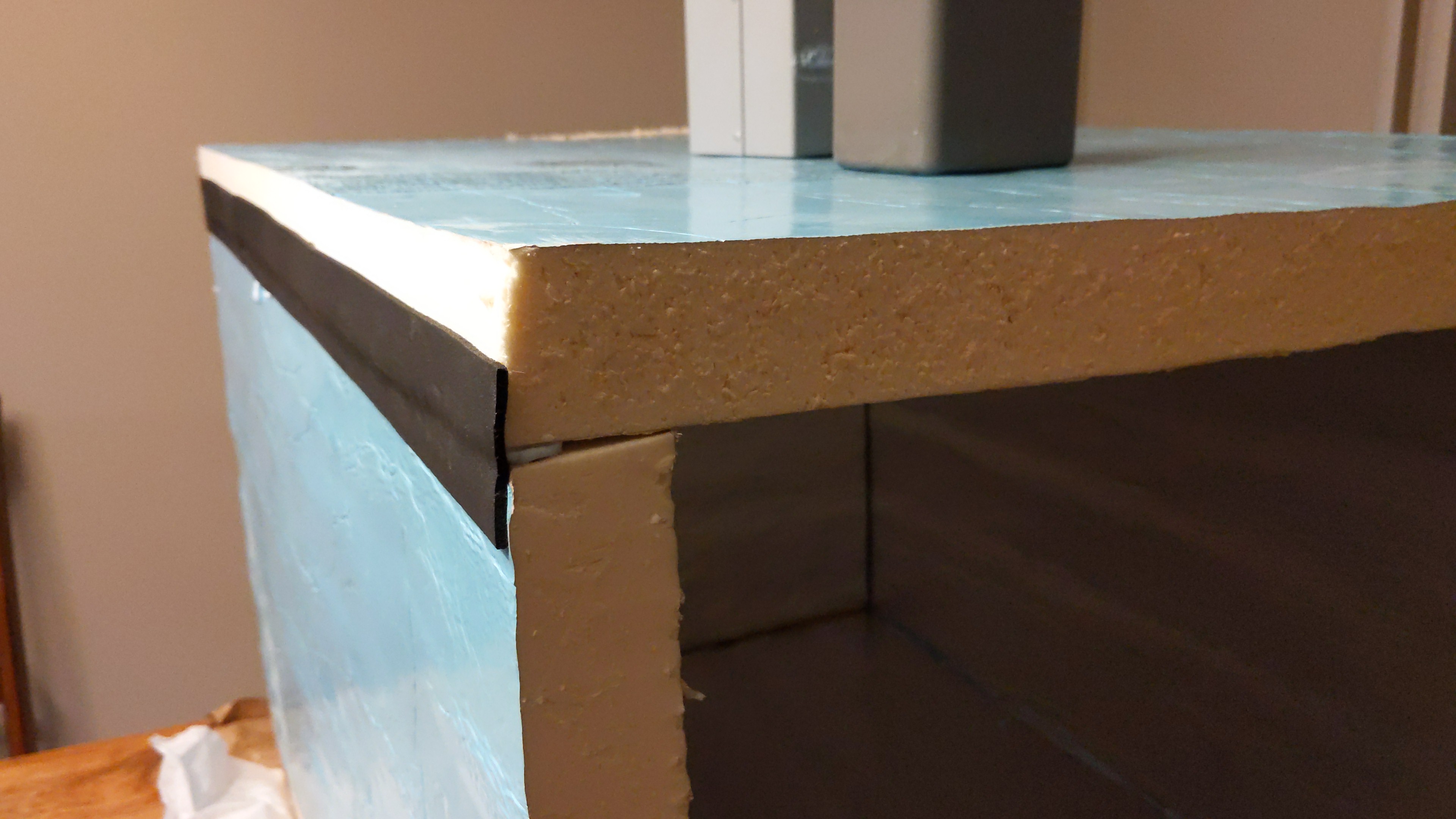
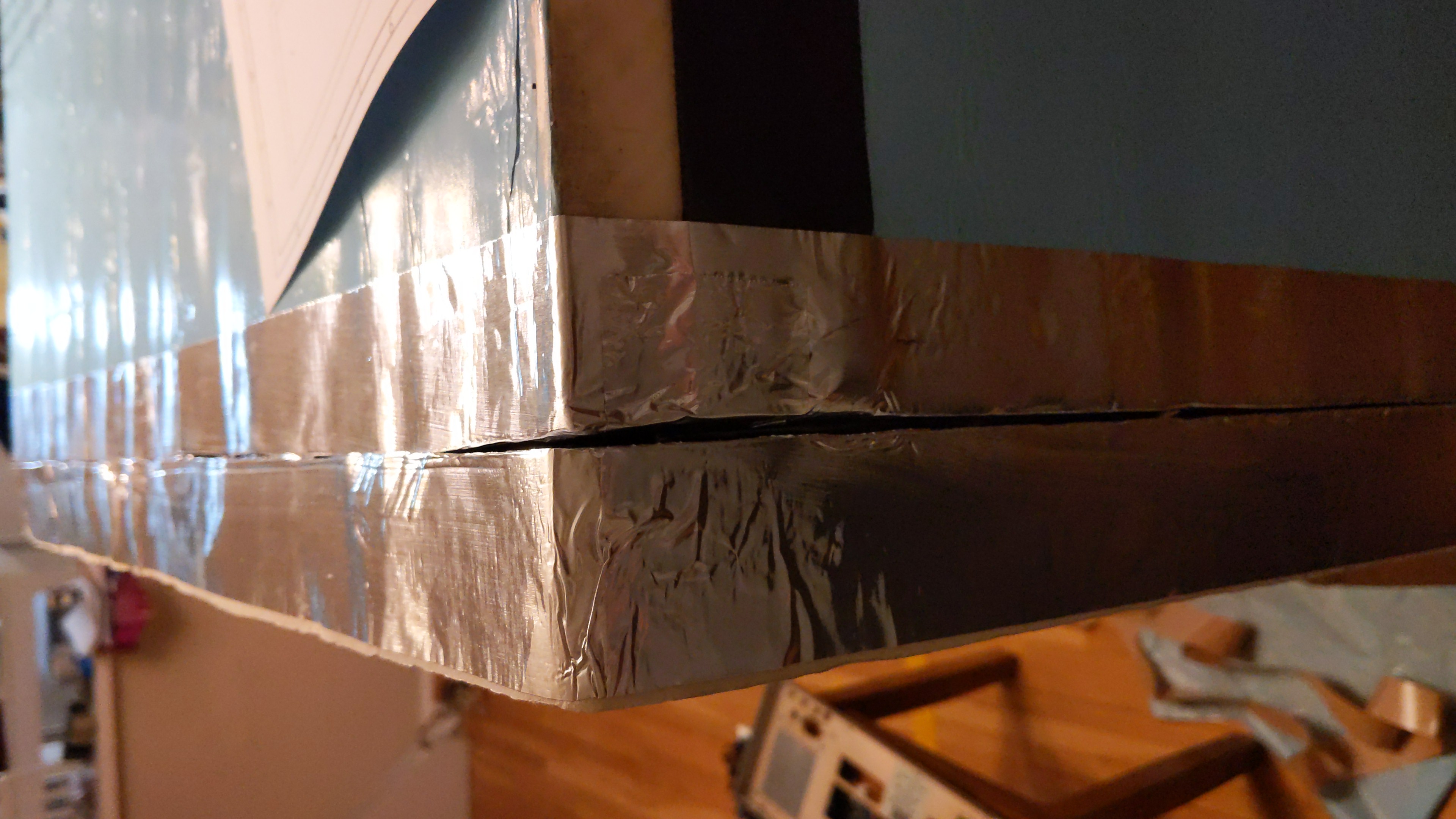
Foam is relatively easy to deform, so to improve reliability and better practical use edges faced with aluminum thin foil. In final use there will be also sealing gasket around the front and rear lids to ensure air-tight seal during chamber operation.
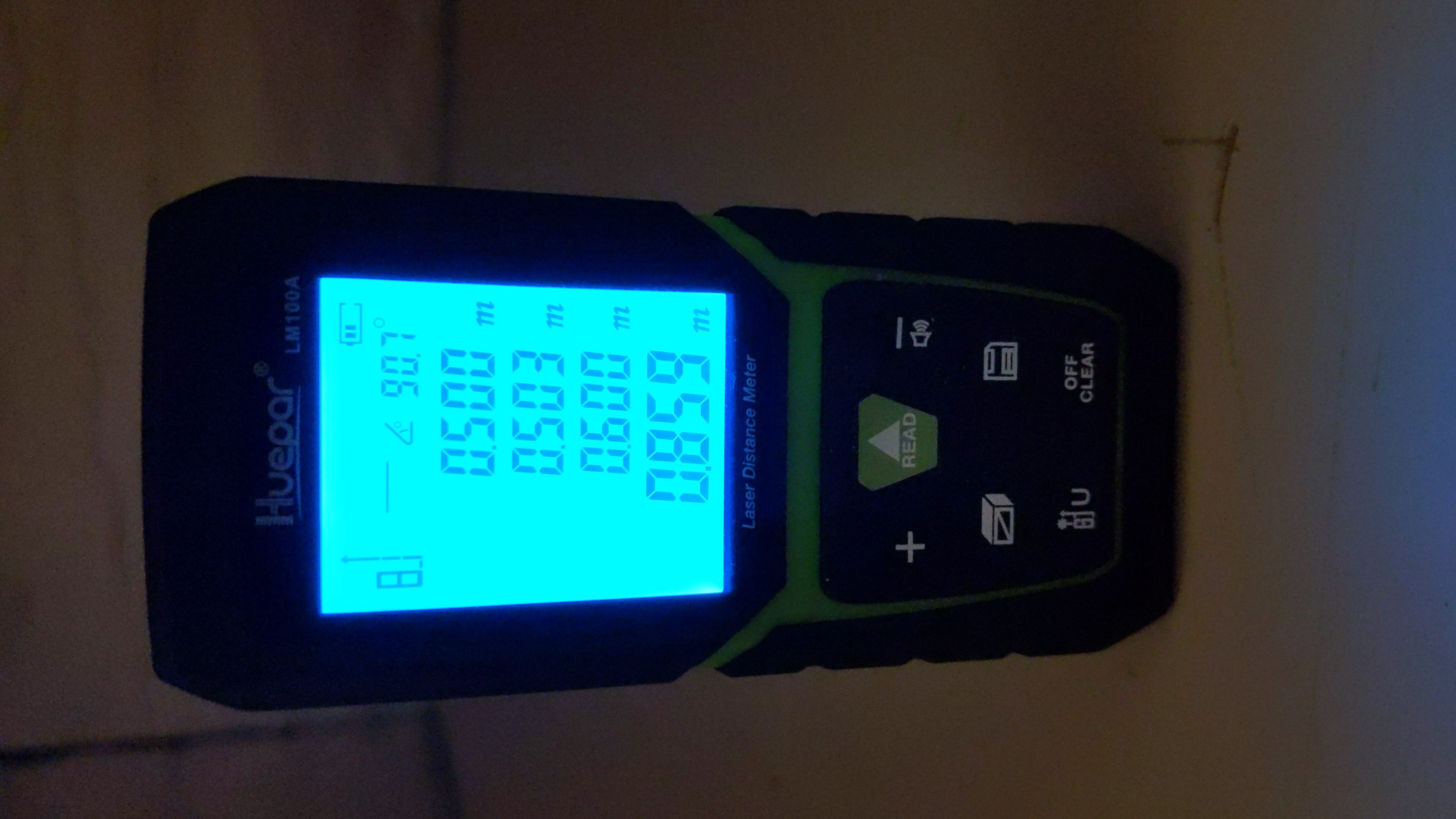
Inner dimension requirements are also met:
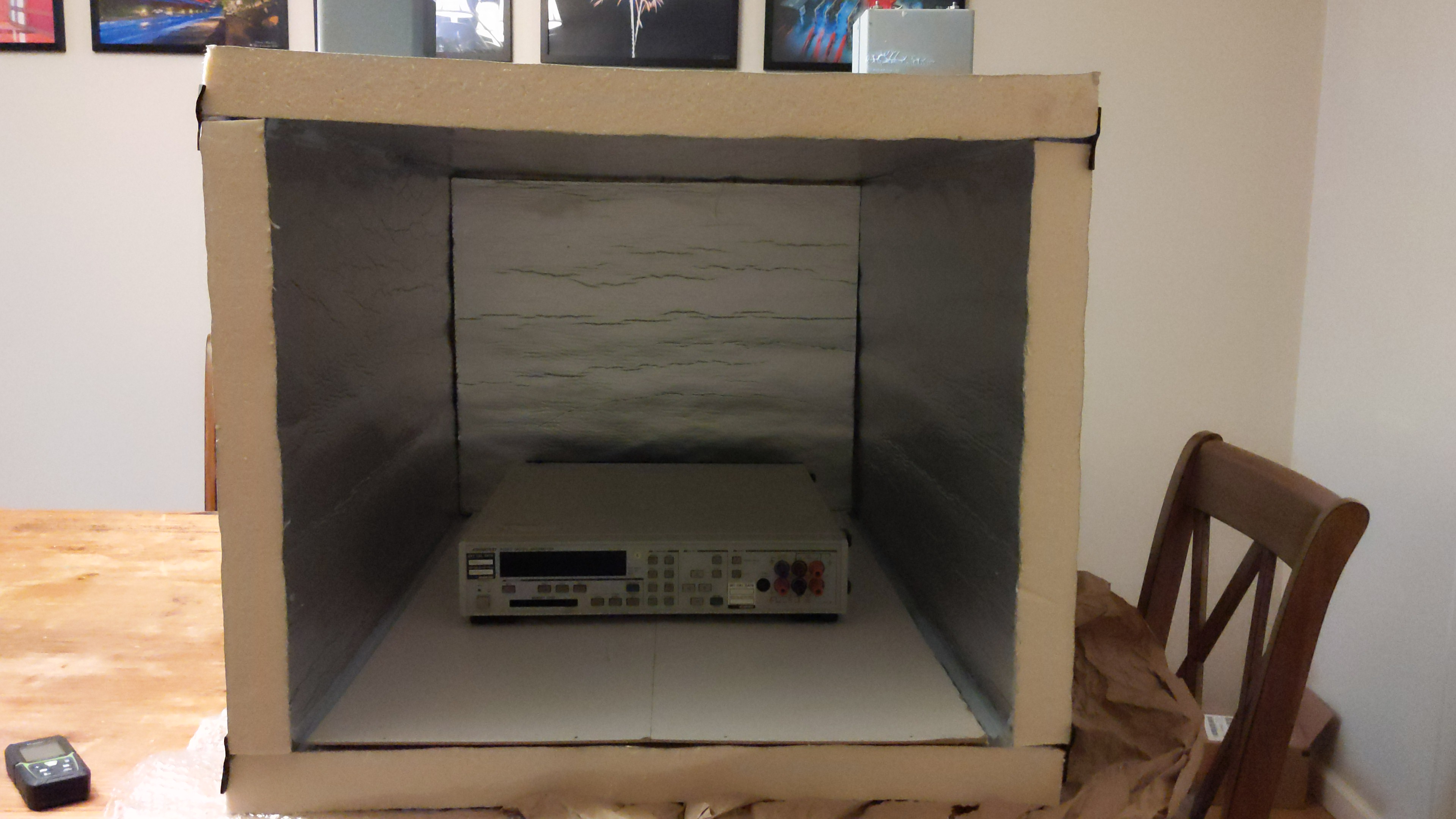
First test with small 40W TEC, empty chamber
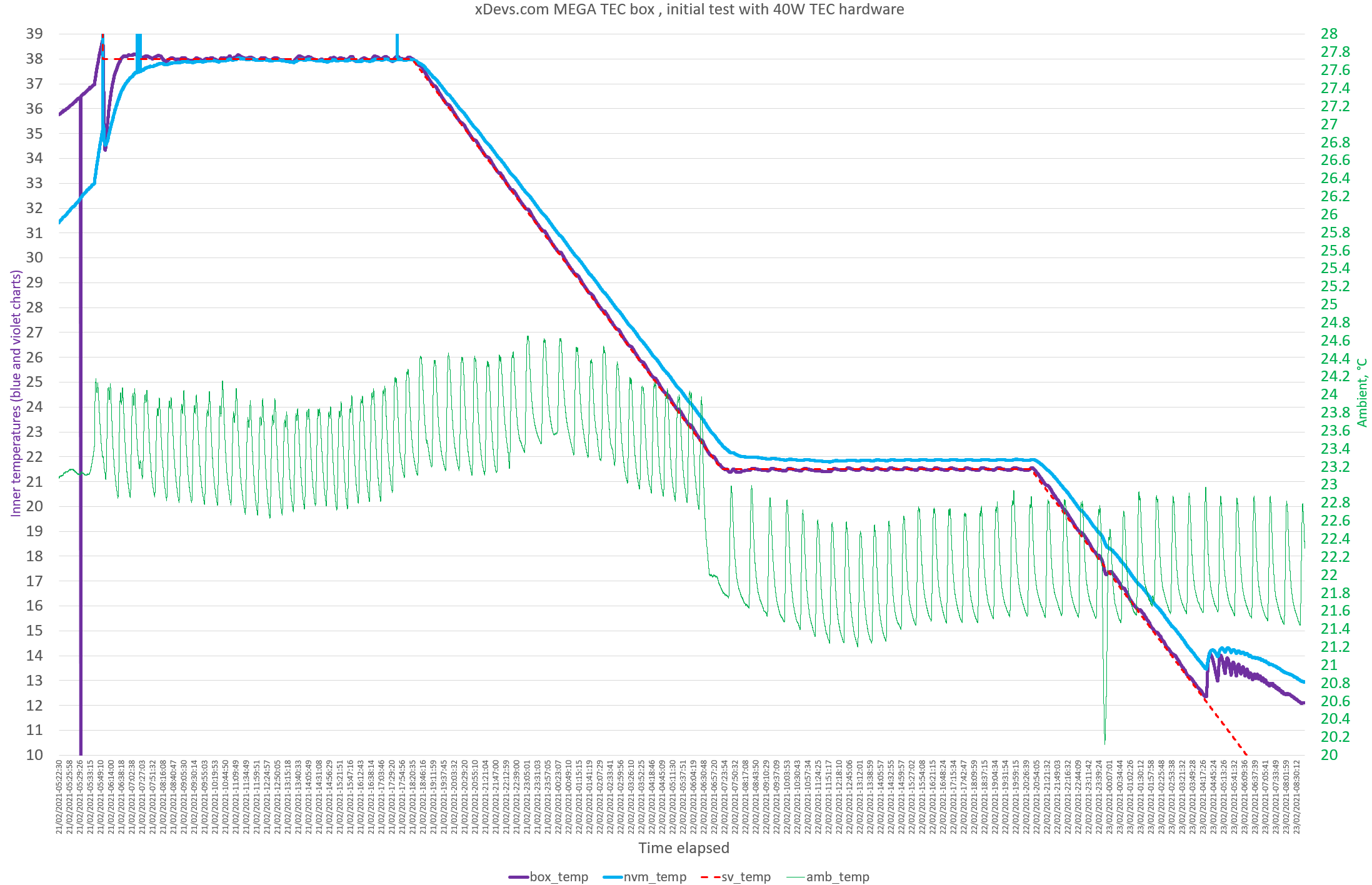
As chamber is curing, I’ve put old electronics and decided to run a 132 hour sweep from +38°C to +5°C and back with help of only 40W TEC module. This will give initial idea if such large chamber concept on the right track.

Vicor AC-DC supply provides +12V for watercooling pump/radiator fan and +6V for inner chamber mixing air fan.
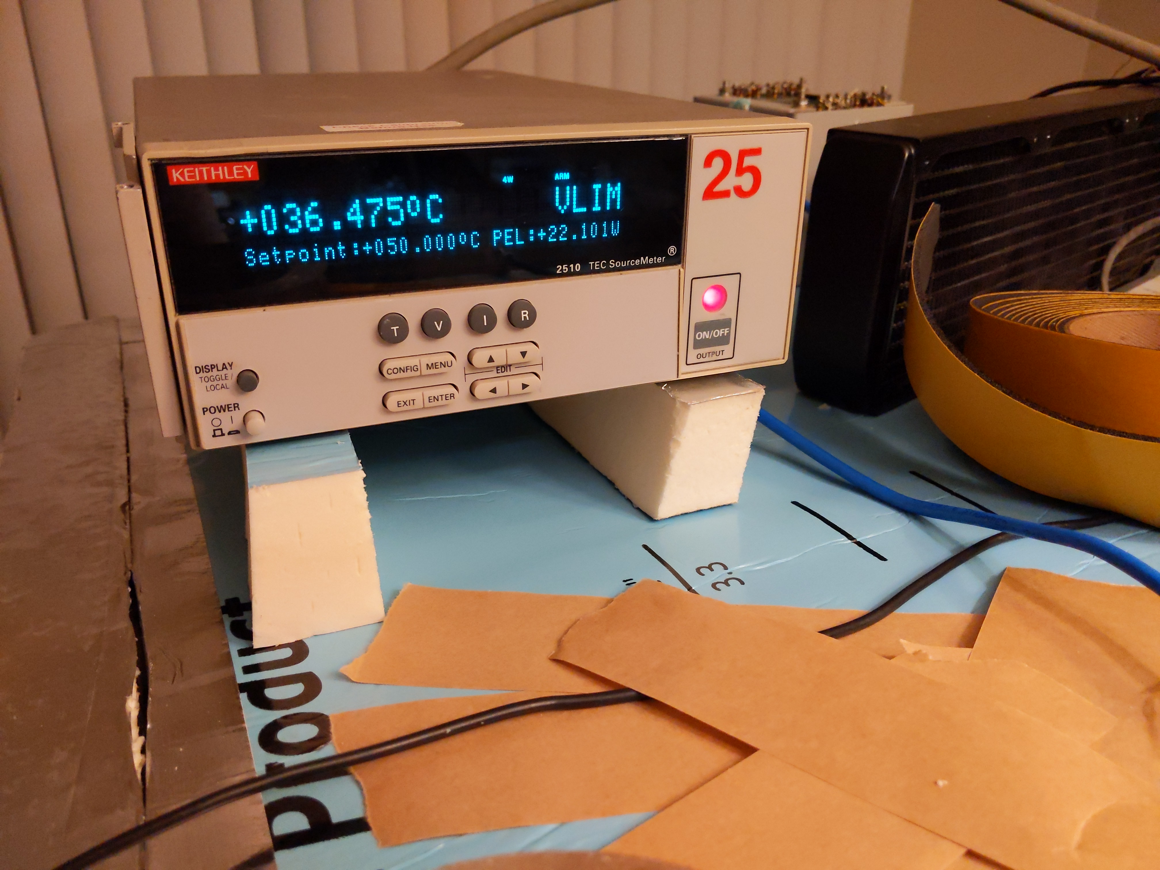
Good old Keithley 2510 TEC SMU was used as temperature PID-controller.
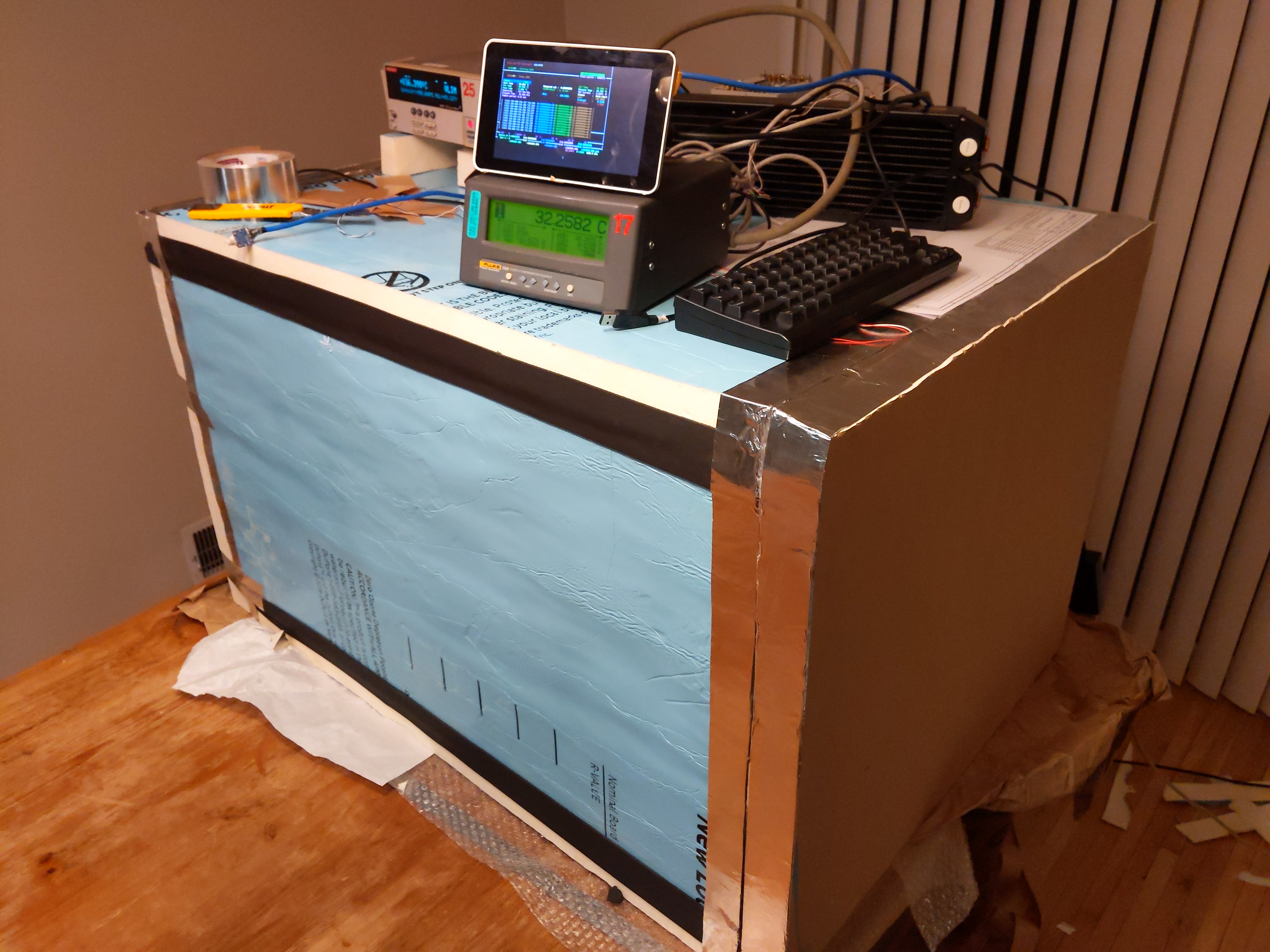
Additional measurement was also taken with calibrated Fluke 1529 Chub-E4 + Omega RTDCAP PT100 sensor.
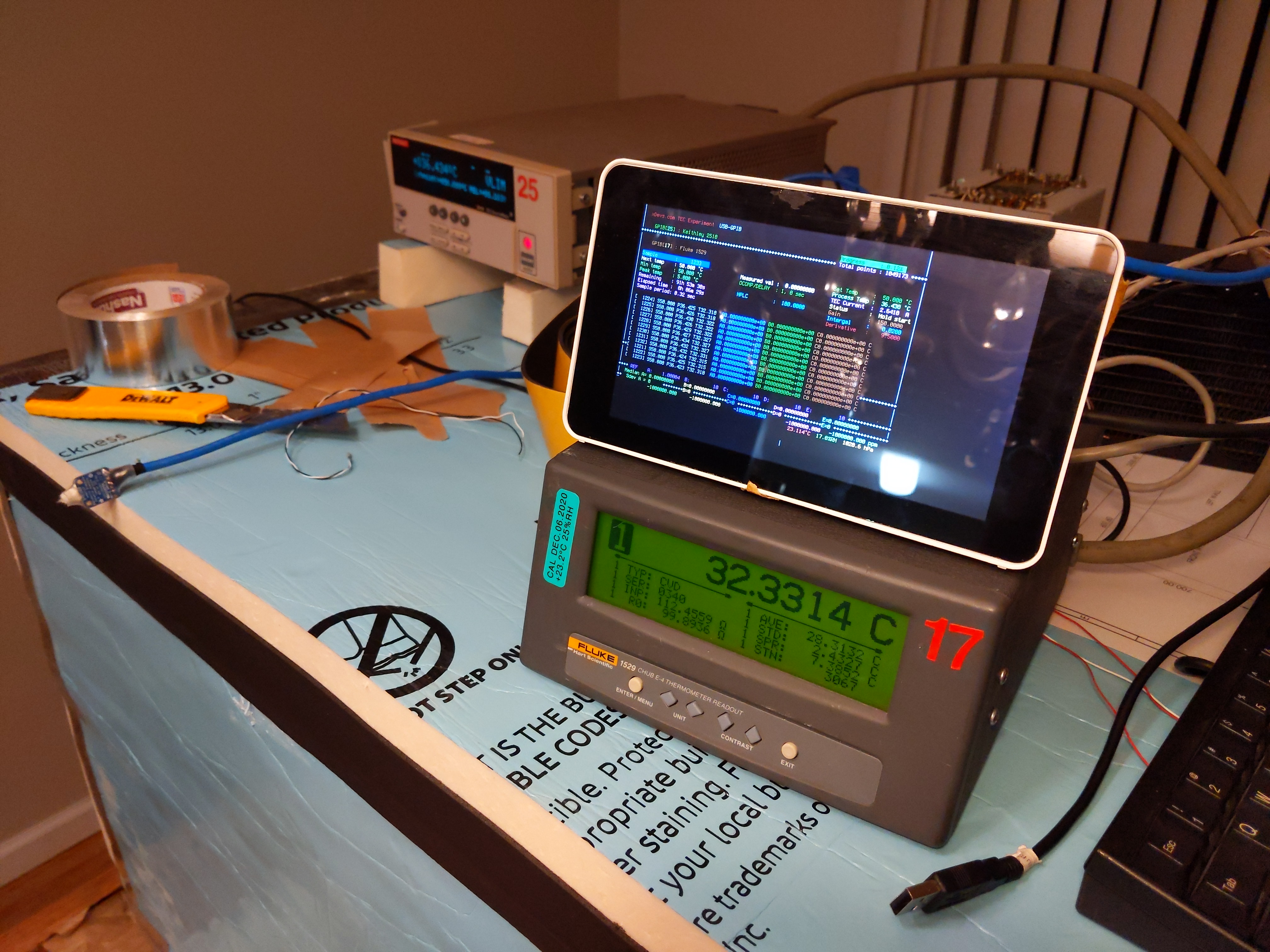
Raspberry Pi 3 used to run teckit application and store measurement results into DSV-file.
Plot showing constant +38 °C set point and beginning of the ramp down.
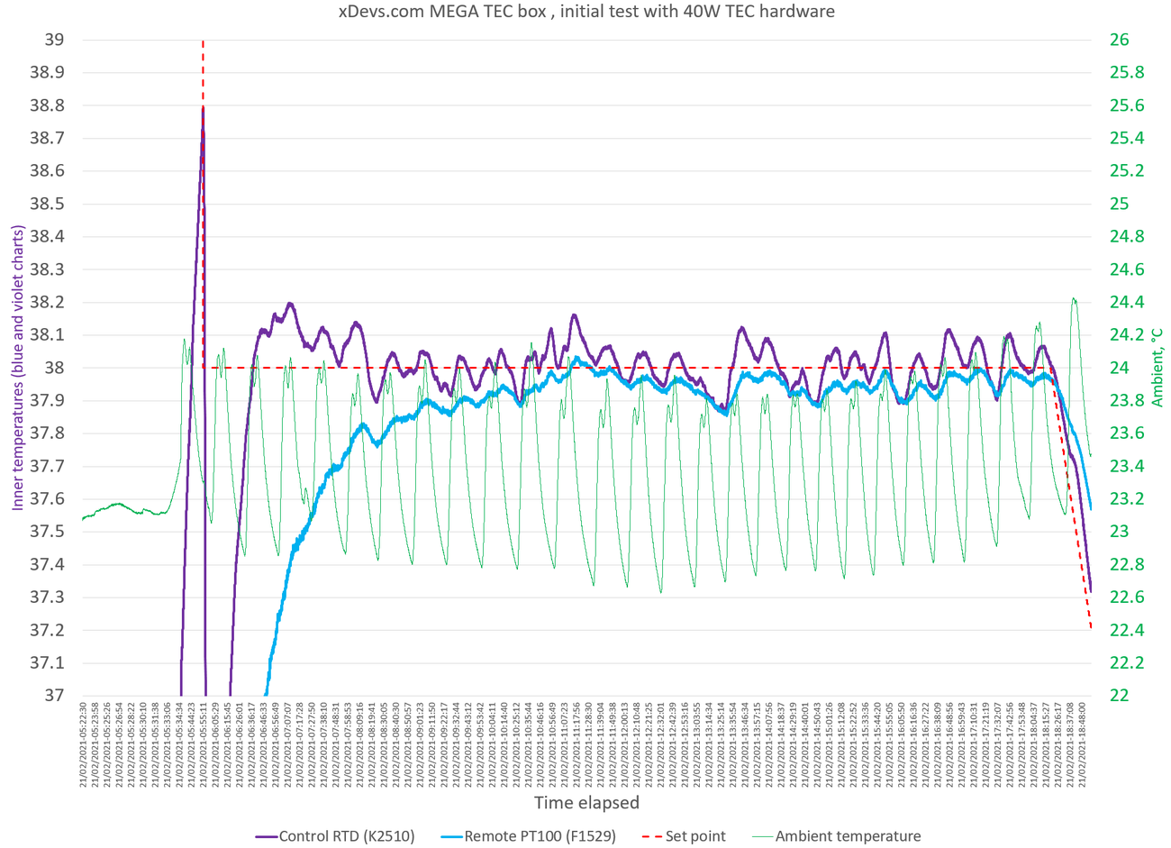
While result is mediocre versus desired spec, it is actually better than I have expected. Distance between remote RTD sensor and control RTD is about 50cm inside chamber.
Major drawback of large volume is slooow response, so that will be investigated later on with use of more powerful TEC setup and angry fans to mix air faster.
Updated test run:
Also two-stage Edwards E2M8 vacuum pump arrived to try pressure control for this chamber prpject.
It is a story for later time however.
Initial tests of the DC Voltage temperature coefficient with different DMMs
Large size chamber aimed to perform temperature stability benchmarks of commercial multimeters, such as manufactured by Fluke, Keithley, Keysight or Datron. First experiment to run Advantest R6581T. I have setup Fluke 5720A calibrator to source stable +10.000000V into DMM placed in chamber and logged readings into CSV-file. While readings are collected temperature in chamber was slowly changed from +18 to +28 °C.
Temperature reference was taken from Fluke 1529 Chub-E4 thermometer and Omega RTDCAP-100 platinum sensor, located near the DMM’s front of the input ports.

This run resulted in next performance plot:
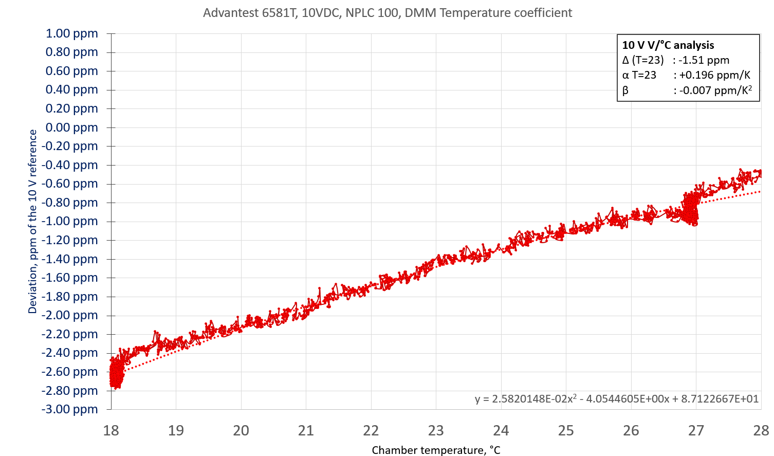
Not very good, but not horrible either.
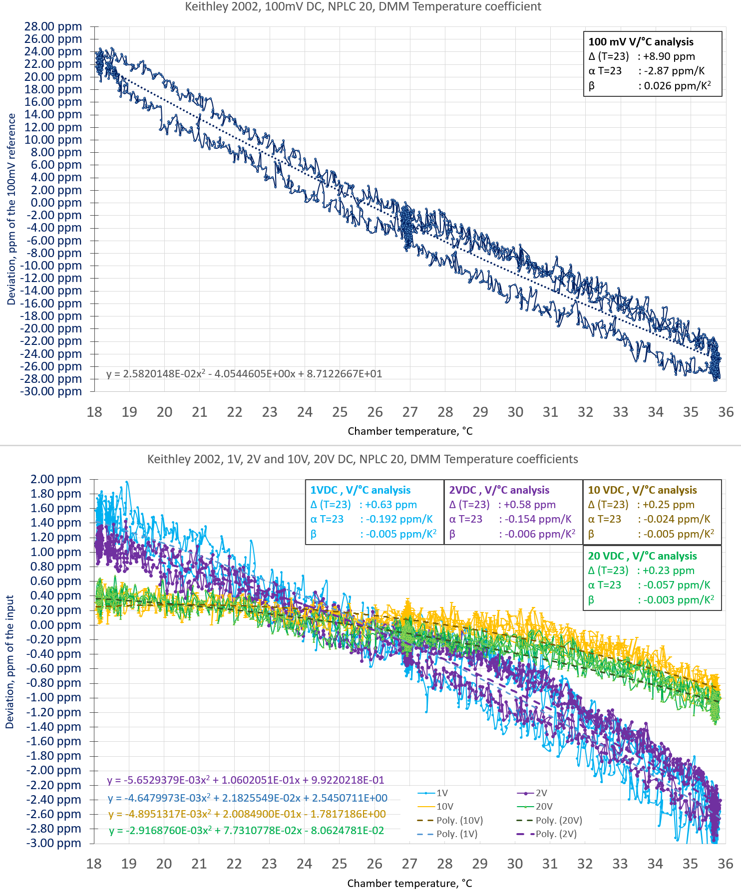
Next patient, 8.5-digit Keithley 2002. To make it more interesting I have sourced multiple voltages and measured three ranges in sequence. Sequence is simple:
1. Select 200mV range, source 100mV into DMM, wait soak time for signal to settle, take a reading. Source and control 3458A outside of chamber also wired as reference.
2. Select 2V range, source 1V into DMM, wait soak time for signal to settle, take a reading. Source and control 3458A outside of chamber also wired as reference.
3. Select 2V range, source 2V into DMM, wait soak time for signal to settle, take a reading. Source and control 3458A outside of chamber also wired as reference.
4. Select 20V range, source 10V into DMM, wait soak time for signal to settle, take a reading. Source and control 3458A outside of chamber also wired as reference.
5. Select 20V range, source 20V into DMM, wait soak time for signal to settle, take a reading. Source and control 3458A outside of chamber also wired as reference.
Then repeat whole cycle on for next temperature step. Temperature was slowly increased and decreased with smooth ramp. There was a hold time at the middle (+27°C point) for 4 hours to see if any effects related to hysteresis/settling time in box.

200mV range result is somewhat meh, but 2V and 20V ranges are quite impressive for a little meter. To give some perspective, most of HPAK 3458A’s have worse temperature stability (without use of ACAL) than this Keithley 2002.
Now running more interesting unit which is famous for it’s hot temper and 40W. Somebody may say that Fluke 8508A is filled with ultra-fancy highly-stable components and that’s why it does not need ACAL hacks like cheap patchjob from competition? Well temperature sweep from +18 to +28°C later can reveal the facts.
Temperature coefficient measurement for ESI SR104 10000 Ω standard
Another application for large TEC-chamber is to perform temperature stability study of large but passive devices, such as ESI SR104 standards. For this test two ESI SR104s were placed in chamber, during the ongoing interlab transfers between our NJ and FL xDevs labs.
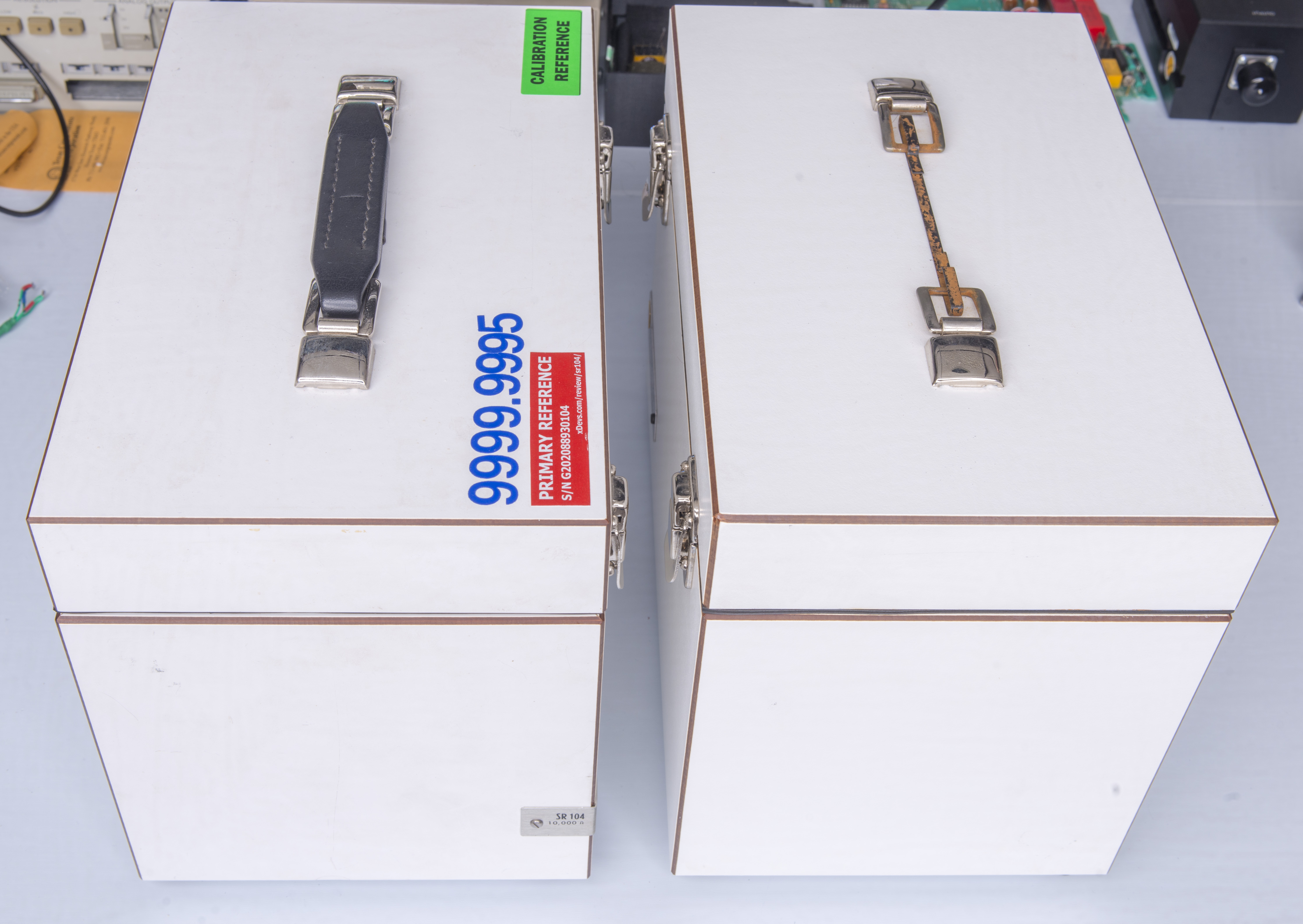
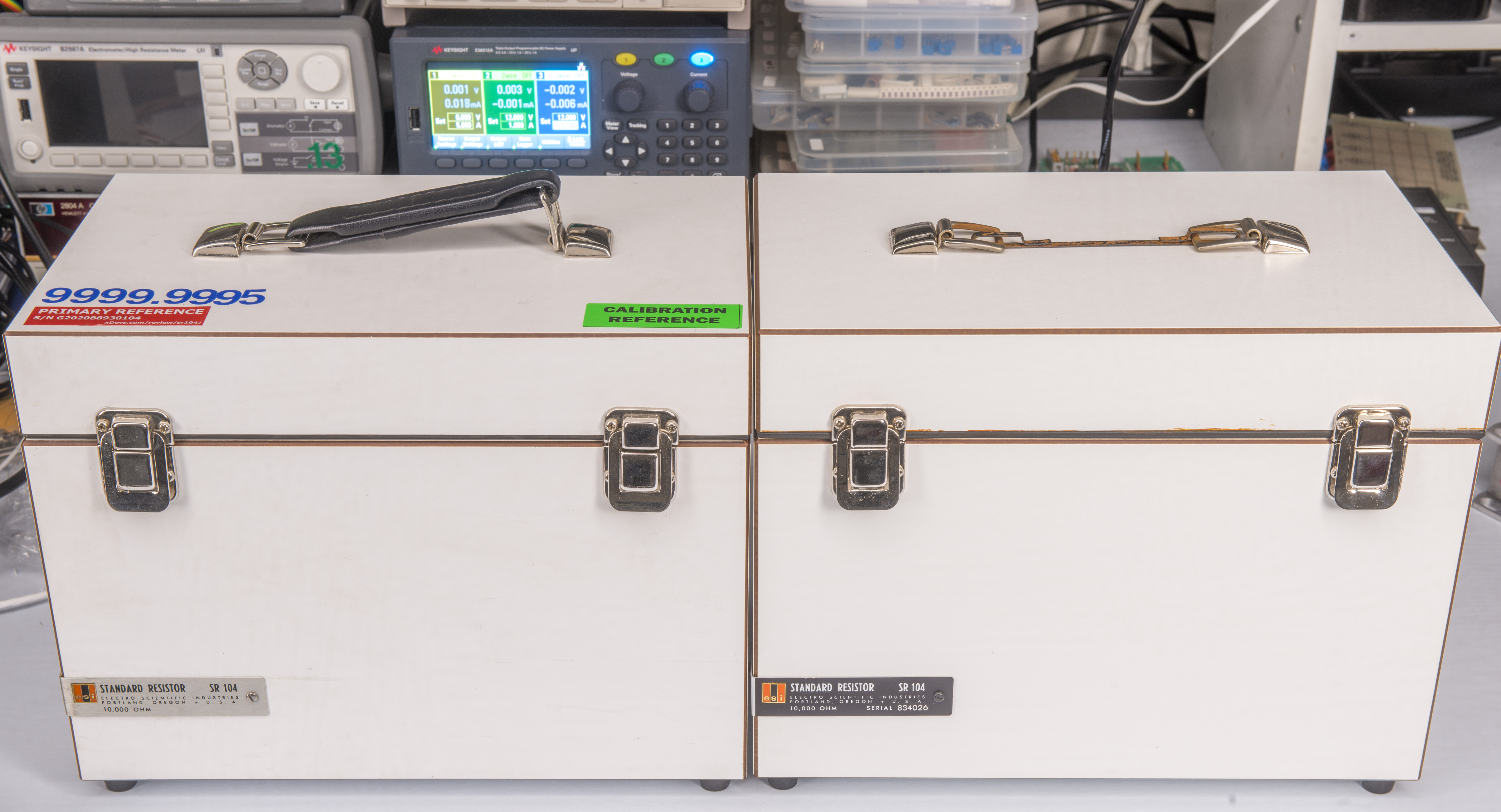
Factory labels with temperature stability data and calibration offsets:

To monitor the environment condition during shipping transit standard was bundled together with inexpensive AZ 88163 THP USB datalogger. This datalogger store temperature, humidity and pressure readings from internal sensors into memory. Data can be further exported to CSV or PDF report when plugged into computer USB A port.

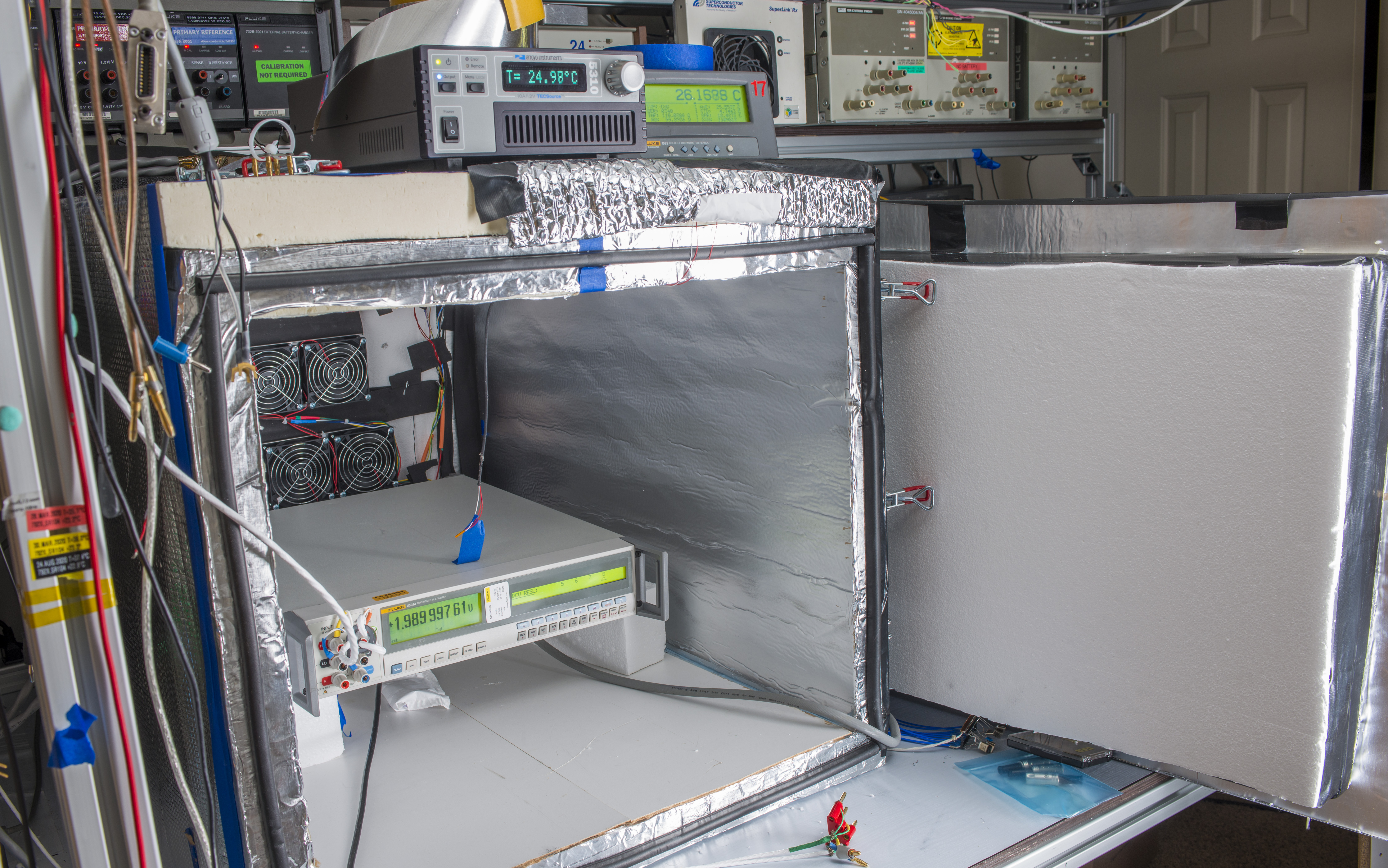
Measurements performed in new large TEC-driven air bath xDevs.com chamber. Chamber design, build and performance discussed in this dedicated article. Both SR104’s were placed in chamber and wired to external Datron 1281 8½-digit multimeter . 3rd check standard (Fluke SL935) used as the verification source to ensure that Datron 1281 does not have stability or thermal coefficient issues on its own. All three used inputs on Datron 1281 were calibrated and corrected to obtain same reading to allow good resistance transfers with 3 standards.
Test run was automated using xDevs.com’s Python app TECKIT and Keysight E5810A GPIB interface . Initial temperature in airbath was set to +18 °C then temperature was slowly increased to +23 °C where it was kept for 4 hours. Next temperature ramped to peak +28 °C to hold for 8 hours. Then thermal slope was reversed and final temperature +18 °C was obtained again. Temperature slope speed was fixed at 0.00694 °C/minute. Settings used for TECKIT are:
sv_start            = 18.000     ; Chamber start temperature
sv_end              = 18.000     ; Chamber end temperature
peak_temp           = 28.000     ; Top soak temperature
delay_start         = 0          ; Delay before any operation start, seconds
slope               = 24         ; Hours, Time for slope (symmetric positive/negative) ramp
time_start          = 12         ; Hours, Initial hold temperature time, before positive slope starts
time_dwell          = 4          ; Hours, Dwell temperature duration time at peak-start/2 temperatures
time_hold           = 8          ; Hours, Hold temperature duration time once reached peak_temp
time_end            = 12         ; Hours, Final temperature duration once rampdown finished
slope_shape         = lymex_step ; Advanced shape type, lymex_step = soak time_start in middle of the ramps
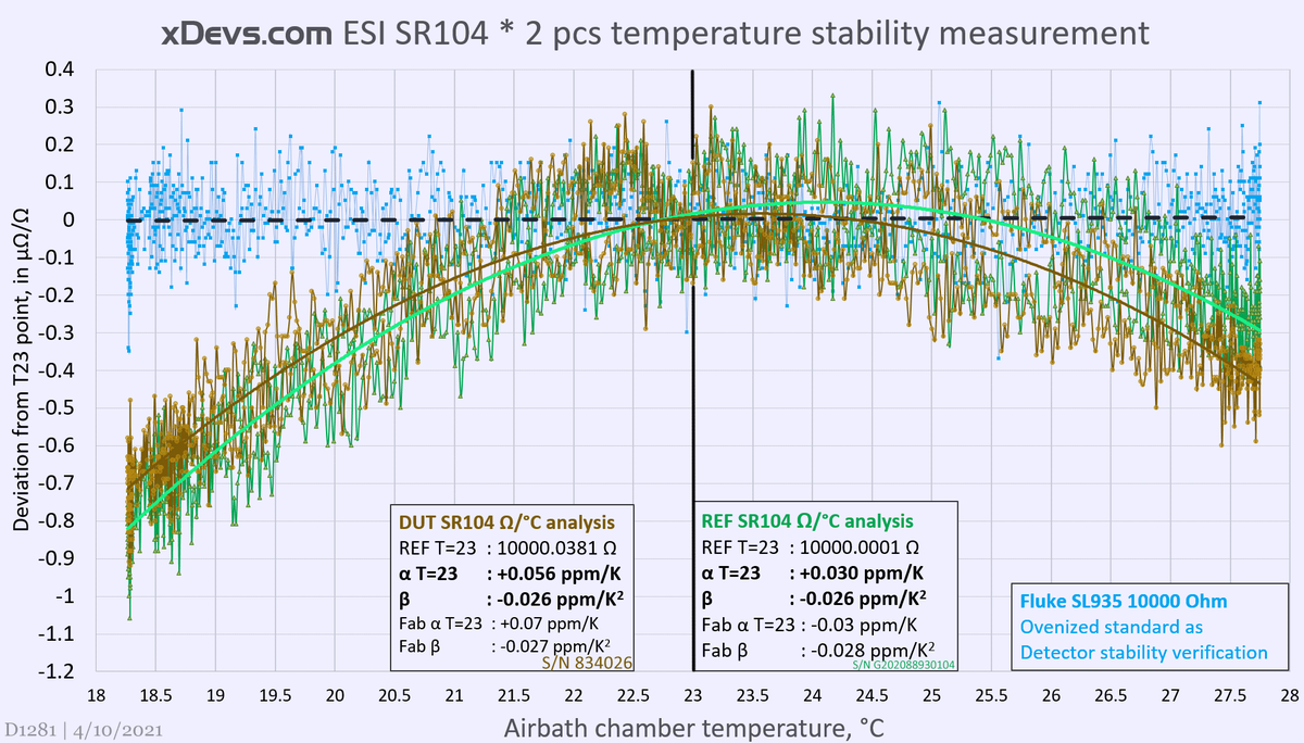
Results are pretty good. First we can notice relatively large amount of noise due to DMM internal current source and low voltage amplifier noise. Overall noise is about 0.3 ppm peak to peak. There is also slight hysteresis, which suggests that wirewound resistive element inside ESI SR104 may require some longer time to recover after 10 °C excursion. This test took 89 hours. Mostly such long time is due to large mass of the oil in SR104’s tank. Such mass caused long thermal delay around 9 hours during the test.
First we can check green reference SR104 data. It was last calibrated year ago by PI on 3/17/2020. Standard was assigned with value 10000.0041 Ω at test current 300 µA with uncertainty ±0.15 ppm, but I have low confidence in this result, as previous history on this standard and our own measurement transfers suggest value around 10000.0026 Ω ±0.2 ppm instead. This standard will be recalibrated by high-end resistance laboratory in coming months and we can repeat measurements to obtain fresh traceable resistance reference at xDevs.com’s lab.
Back to results. Obtained measurement at temperature point +23 °C equals 10000.0001 Ω ±0.3ppm. Temperature coefficient from lid factory certificate is outlined on a plot with label “Fab α” and “Fab β” values. Measured and calculated α and β shown in bold font. Reference SR104 (green color on plot) have opposite sign α value but β match almost exactly.
52 year old ESI SR104 under test (“DUT” label and plot in brown color) has deviation from nominal +3.81 ppm (assigned 10000.0381 Ω ±0.85 ppm new value). Measured and calculated α temperature coefficient value is slightly lower than factory (+0.056 ppm/°C vs +0.070 ppm/°C). β is almost exact match here as well. This standard will be also shipped for fresh calibration.
Projects like this are born from passion and a desire to share how things work. Education is the foundation of a healthy society - especially important in today's volatile world. xDevs began as a personal project notepad in Kherson, Ukraine back in 2008 and has grown with support of passionate readers just like you. There are no (and never will be) any ads, sponsors or shareholders behind xDevs.com, just a commitment to inspire and help learning. If you are in a position to help others like us, please consider supporting xDevs.com’s home-country Ukraine in its defense of freedom to speak, freedom to live in peace and freedom to choose their way. You can use official site to support Ukraine – United24 or Help99. Every cent counts.
Modified: April 10, 2021, 6:21 a.m.