Intro
In the beginning of 2023 FX module was re-calibrated and verified to ensure 10V LTZ1000A reference is in good shape for the beginning of USA Cal Club Round 3. Everything was progressing slowly but surely with members playing around the kit until end of August 2023 when during one of the measurements return voltage terminal got loose. Small accidents like this were bound to happen earlier than later and were actually one of the reasons why I spent efforts to provide LTZ based module in a first place. Independently from any metrological results, I was curious to see how well a DIY device with low-cost ($600 USD in parts) would fare in frequent shipping, use in various hobby labs with members of different expertise and equipment. This is the second repair on the unit, also related purely to output connectors.
Originally USA Club’s FX module came with a pair of Pomona 3770 posts. But their quality is so bad that after only a few uses, the plastic knobs on the posts got cracked, rendering use of the connector nearly impossible. I am used to robust posts that Fluke installs on many of their metrology instruments, as well as good posts that HP used in 3458A and power supplies. This means that connectors and cables can be tightened very well, ensuring good connection between copper surfaces and helping to mechanically scrape thru any microscopic oxides layer. Pomona can’t handle this and was replaced with old custom copper only posts used previously in some old L&;N bridge. However, as this second repair will reveal, the plastic washer to keep the post tight in a chassis port is old and got cracked after this many re-connections.
FX reference module built and provided for USA Cal Club was never designed to be rugged and resilient for daily use and frequent shipping like users might expect from commercial equipment. And a few years of shipping and second damage on connectors highlight this shortcoming well. This was accepted compromise in favor of small size and cost.
In this article, I will document and show the whole repair process and demonstrate re-calibration of the reference to regain the confidence in the 10V output quality and stability. Actual repair was just few hours of time, but further verification and measurements took much longer time to establish low uncertainty required for LTZ1000A performance targets. There is no way to speed up or bypass the sheer time demands when working with instruments capable to operate at stability level below 1 µV/V. No AI, statistical sugar or deep learning or ChatGPT improvement can generate the missing data to determine the physical behavior of the complex active zener device with op-amps and combination of thermal, mechanical and electrical feedback loops.
Kit as received
After opening the FX box up the failure was obvious. Plastic washer that held LO post snapped in half and post got free in the chassis. This in turn caused it to turn freely, ripping the connection to a coax shield clean off.
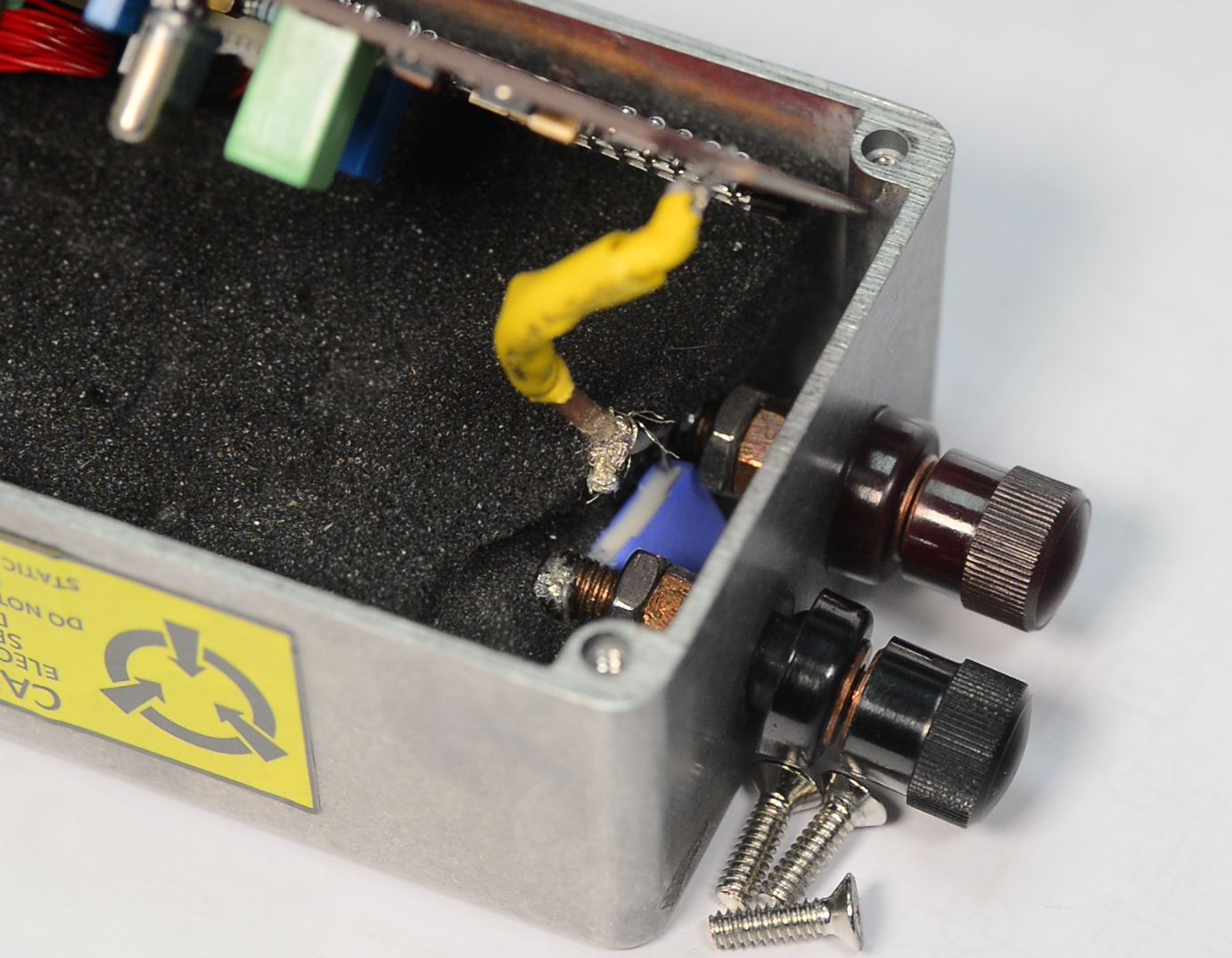
Easy repair task, just replace the connectors until the next time. This is 2nd time USA Club getting new connectors, first time it was piss poor quality Pomona 3770, now it’s old plastic connector failure. Hopefully 3rd time is the charm :).
FX repair
The actual repair process was captured on video at xDevs.com lab and provided in a public video embedded here. It was a simple process and did not involve any alterations on actual FX voltage reference PCBA. I expected minimal impact on output voltage or stability performance as no heat was applied to any components, except short cable from PCBA to the new posts. Internally FX module has true 4-wire output with remote sense, but to simplify inexperienced user operation sense signals for both 10V and return potential are tied at the output posts joint permanently. Because the resistance of the sense wire and onboard trim resistors in the voltage feedback loop, actual voltage could change a tiny bit due to few milliohm changes from replacing new connectors.
After ports replacement I let FX to run powered up few hours on 3458A and then moved it to zener array bank for few months of logging.
24 hour calibration
Now, if our job would be just to confirm the 10V output with say 4 µV/V uncertainty and short term stability good enough for quick transfer, one could say 24 hour measurement data set is plenty good for that and most likely would be job done at this point. But I wanted to really see that no drift is developed or hidden, so longer data capture was granted.
Here at xDevs we advocate for data-driven metrology that is based on actual measurements and data points , instead of sheeply beliefs of magical properties of voodoo performance of expensive components and instruments. Lot of time effort and resources spent to obtain multiple different setups to collect, process and analyze voltage data.
Conclusions and summaries only built based on what data shows, and not what datasheet tells us to expect or believe in.
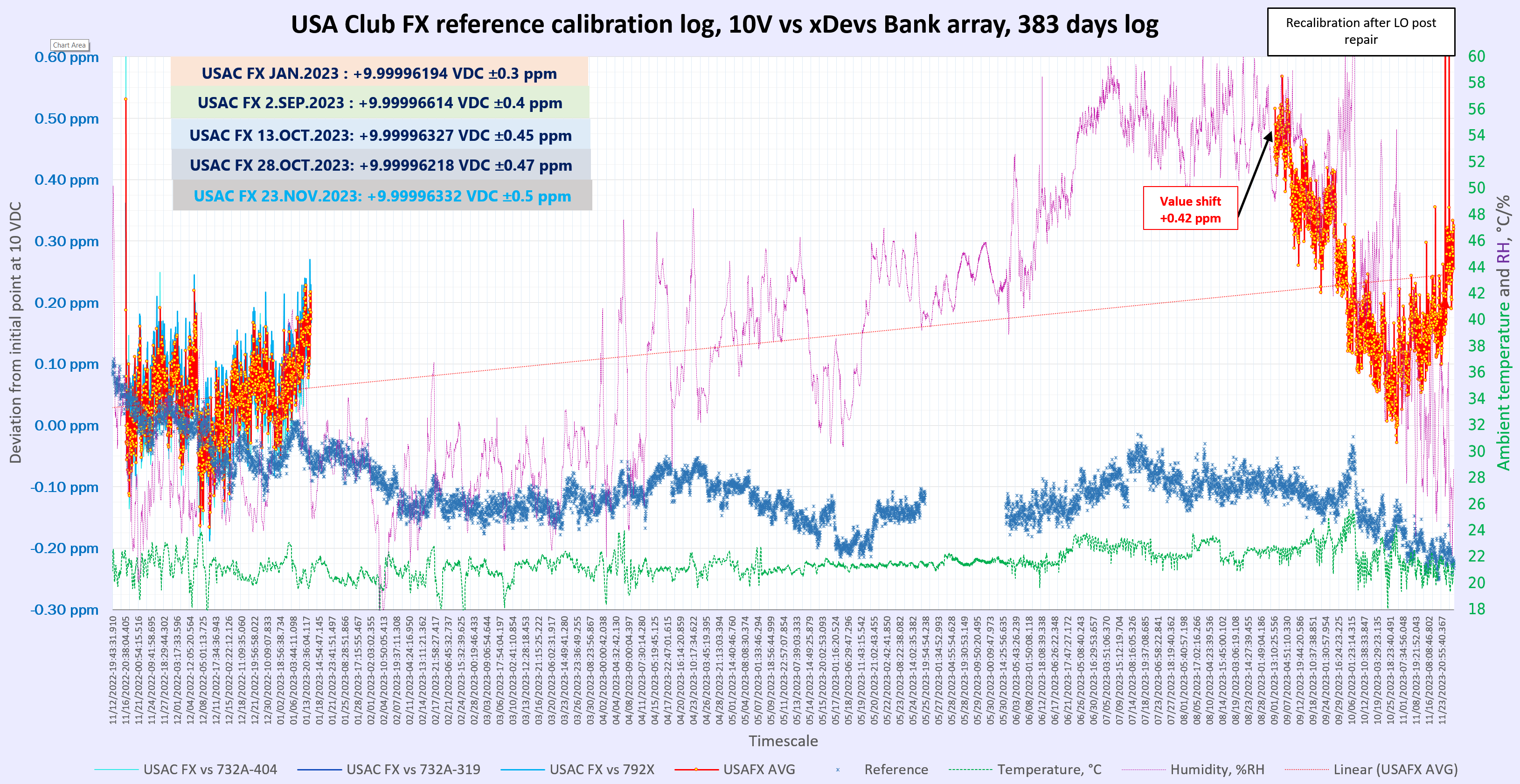
55 day calibration
More data gathering made it pretty evident that collecting a month worth of data was a good time investment. Data now reveals us few interesting observations. Initial value of the unit was determined a little bit high but now it is very slowly going down towards the February 2023 calibrated value. So it is getting better like a good wine? But in world of zener standards ANY drift that does have obvious explanation is a bad news for long-term stability and predictable behavior.
Data drift we see might be caused by magnitude of reasons.
A. Measuring system has systematic error that changes over time?
To verify this idea FX reference was swapped to the different channel which had another stable 10 V reference for 2 days. That provide very similar results within ±0.3 µV/V, which is mostly limited by noise and short-term deviations.
B. FX reference developed temperature dependency on ambient changes?
Shift didn’t look to correlate with ambient temperature measurement in any significant way.
C. Connectors slowly oxidize over time?
Cleaning connectors again with blade didn’t change the result, it was came to same value within noise of the zener and measurement setup.
D. Reference was affected by undocumented stress before posts were broken?
There is no much options to see if there were other shifts since we’d need to have good uncertainty data points in between xDevs calibrations. Perhaps it is something that USA Club members could help with on next round.
E. Trapped humidity slowly escapes from the reference?
Critical components that define most of the long-term drift in USA FX reference such as LTZ1000A, VHP/VHD, network resistors are hermetically sealed.
F. All of the above?
In reality there is rarely just single effect that cause errors in metrology instruments. Likely the effects observed is a combination of multiple effects over the duration of the calibration.
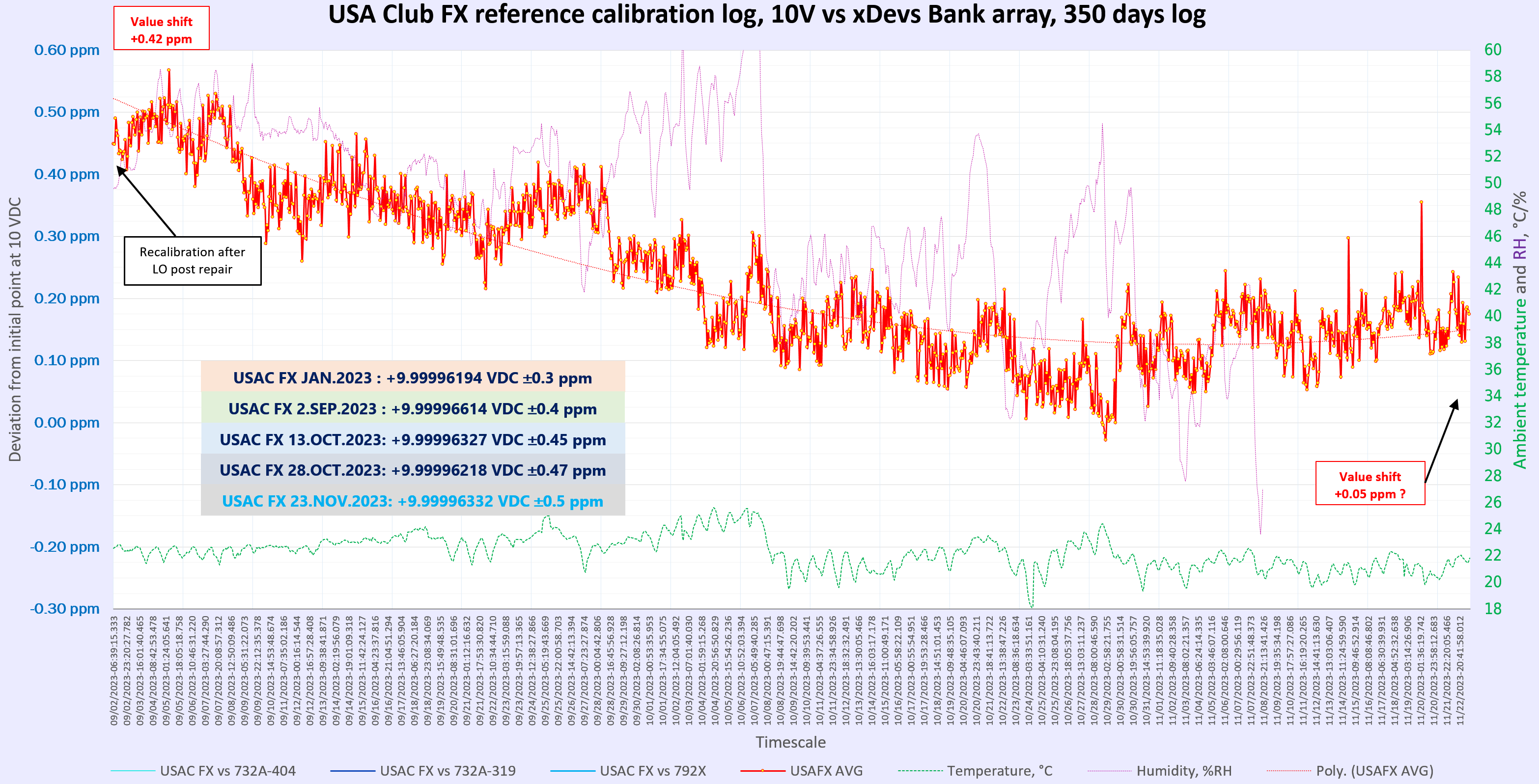
55 day calibration, zoomed in.
This is just previous plot without the past history data from January.
How could these number be trusted?
All calibration data points above are presented under expectation that measurements were performed correctly and can be independently verified. But how this is achieved in reality?
The simplest way to measure DC voltage is to connect a DMM to the source and record a reading into a dataset, together with date/time and support information like environmental sensors and calibration certifications. This approach works good for typical bench top sources and generators, but actually not good enough for high performance DC reference like FX with LTZ1000A zener. Even if we find and use very expensive 8½-digit DMM, it would be equal in drift and stability to FX unit. Temperature coefficient of even the best DMM is much worse than FX’es verified and measured 0.05 µV/V/K. Since typical hobby lab usually does not have strict temperature control or large air-bath thermostats to fit DMM, this means dataset would be heavily correlated to ambient temp, making most of the measurements claims below few µV/V very difficult or even impossible.
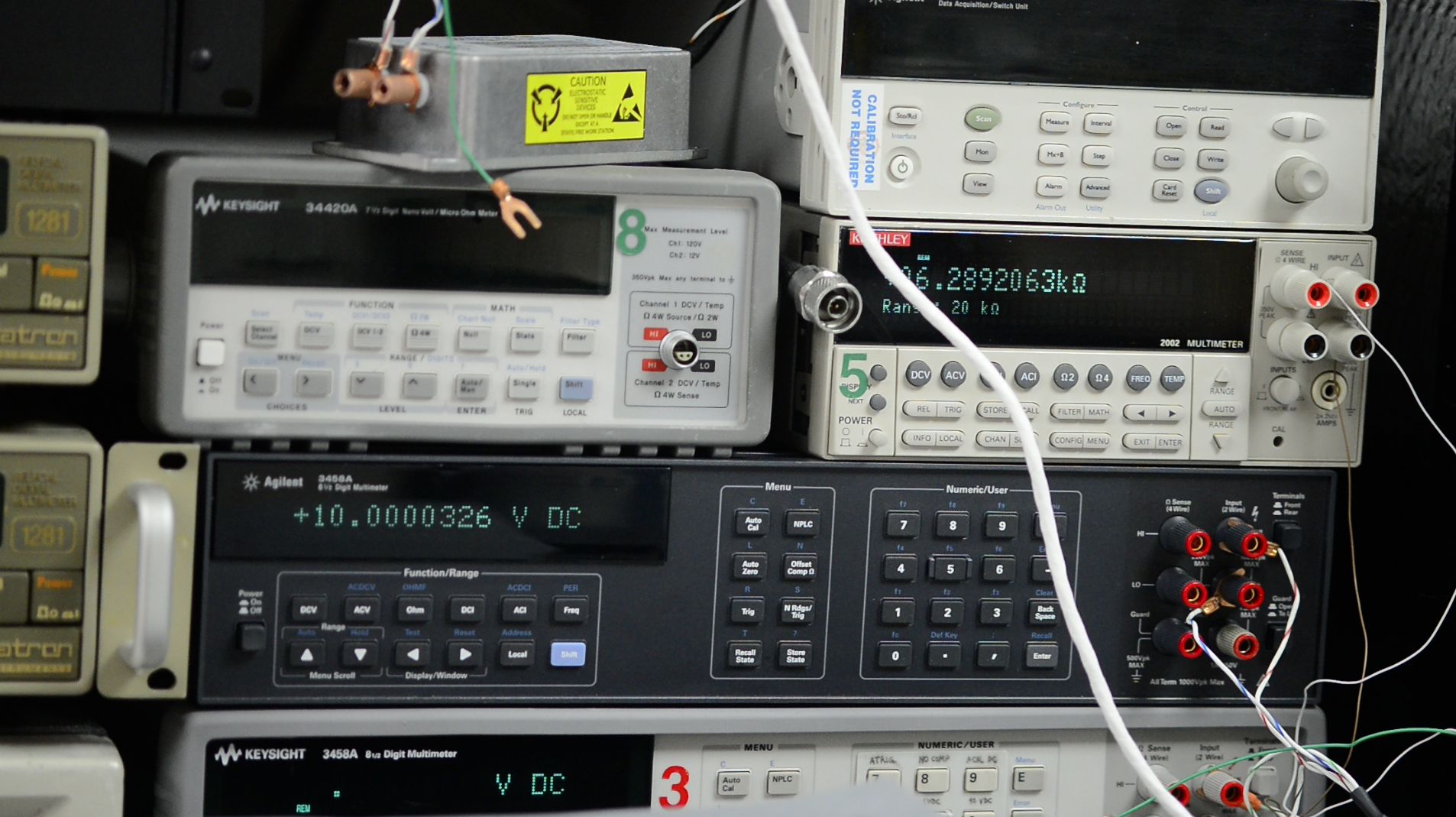
Solution to this challenge is to replace very expensive long-scale DMM (that’s still not good enough) to much cheaper low noise 6½-digit DMM like 34401A or even more sensitive micro-voltmeter such as Keithley 2182A or Keysight 34420A or even older Keithley 182/181. Next component is a second stable low noise 10V reference built with LTZ1000 or ADR1000 zener, or commercial 10V standard like Fluke 732A. People working in quantum metrology might even use the Josephson Voltage Standard as the ultimate 10V source.
And final piece is a programmable scanner/switch to provide polarity reversal so parasitic EMFs due to wiring and contacts metal mismatch can be cancelled out. By using this system one obtains measurement setup capable resolving 0.01 µV/V of 10V range and almost unaffected by temperature changes, ADC noise and detector drift. The largest error source in such setup is usually actual long-term drift of the transfer and DUT 10V sources and their noise.
xDevs.com is able to obtain sub-ppm uncertainty at 10V point precisely due to implementation of such combined measurement system, backed up by large calibrated bank of old commercial zener standards and periodic internal inter-comparisons between our xDevs members. Three key members maintain total 10 x Fluke 732A, 8 x Fluke 732B, few Datron 4910 and array of various other LTZ1000-based devices. Each array is measured fully automatically in opposition configuration and recorded difference in microvolts is stored in the array matrix.
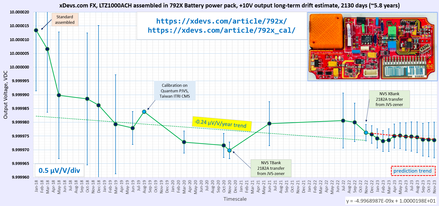
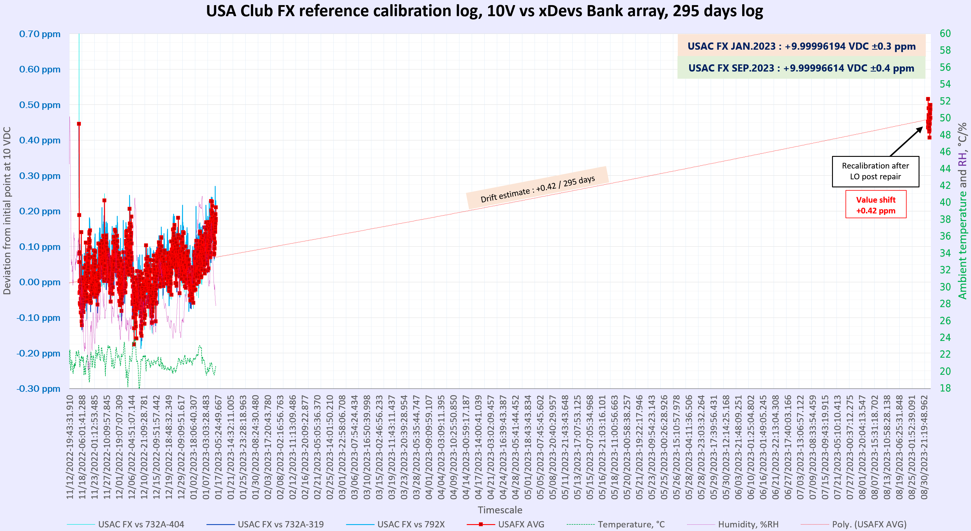
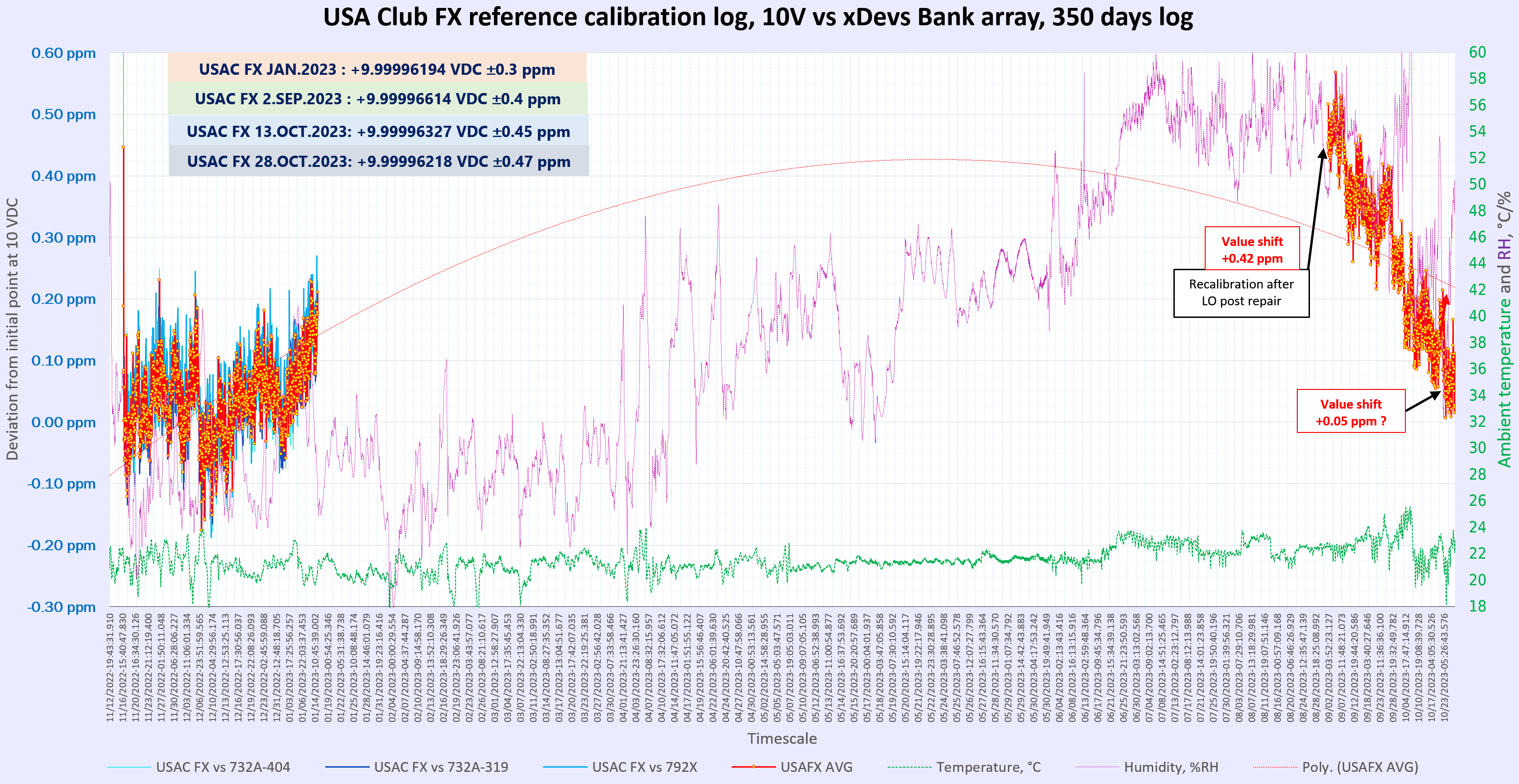
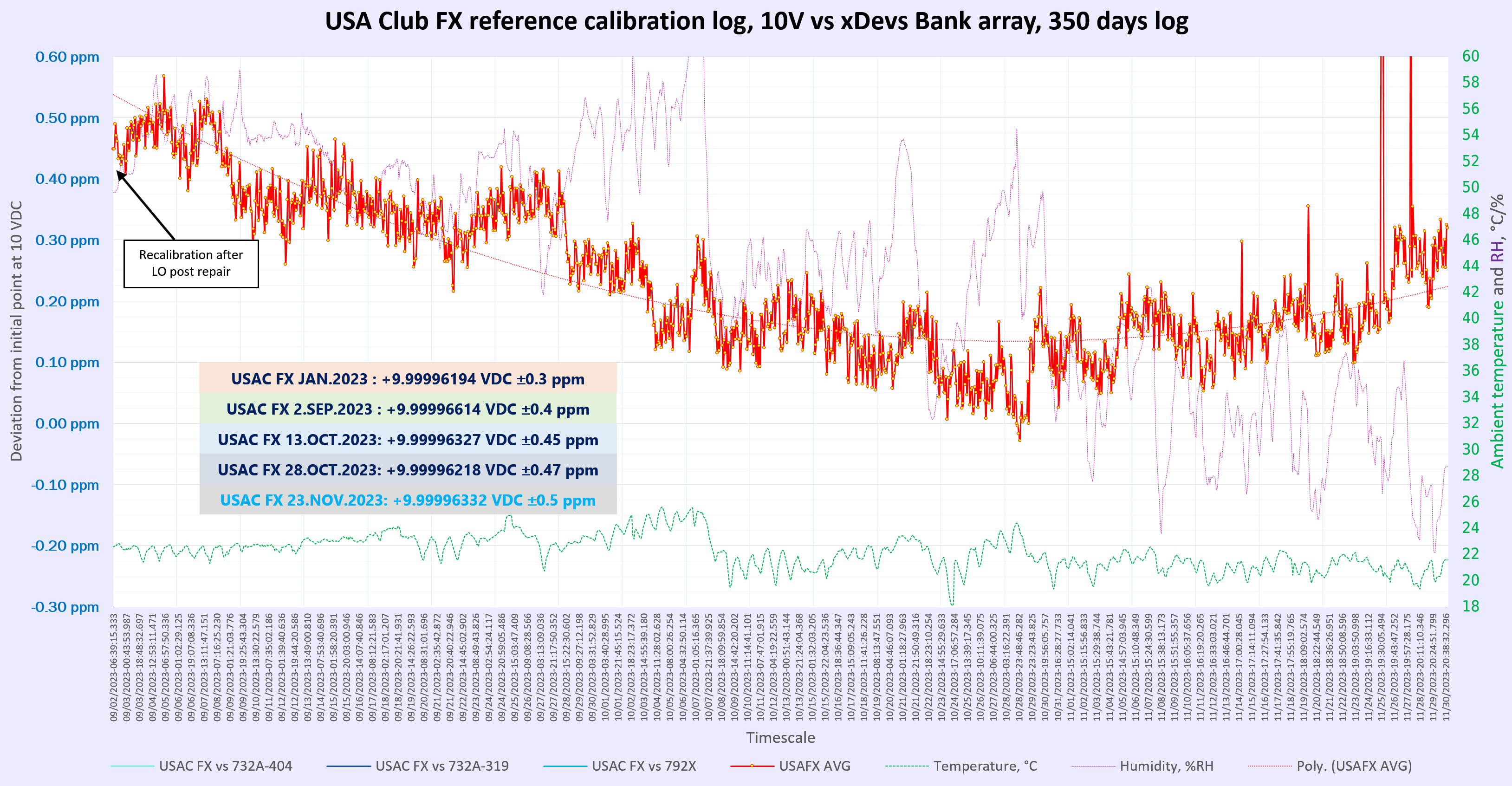
Few times in last 8 years, good zener standards were transported to accredited and high level calibration laboratory to obtain voltage measurement traced to SI realization by JVS. After careful data analysis and verification of travel standard health and shifts due to transportation, the new voltage value is used to determine absolute EMF of each other zener that stayed at home. This approach also helps to share high costs of top tier calibration on our zeners between members. After all the data processed, one can generate long term drift estimate with actual calibration points, like shown for in-house xDevs.com FX-powered standard in a plot below.
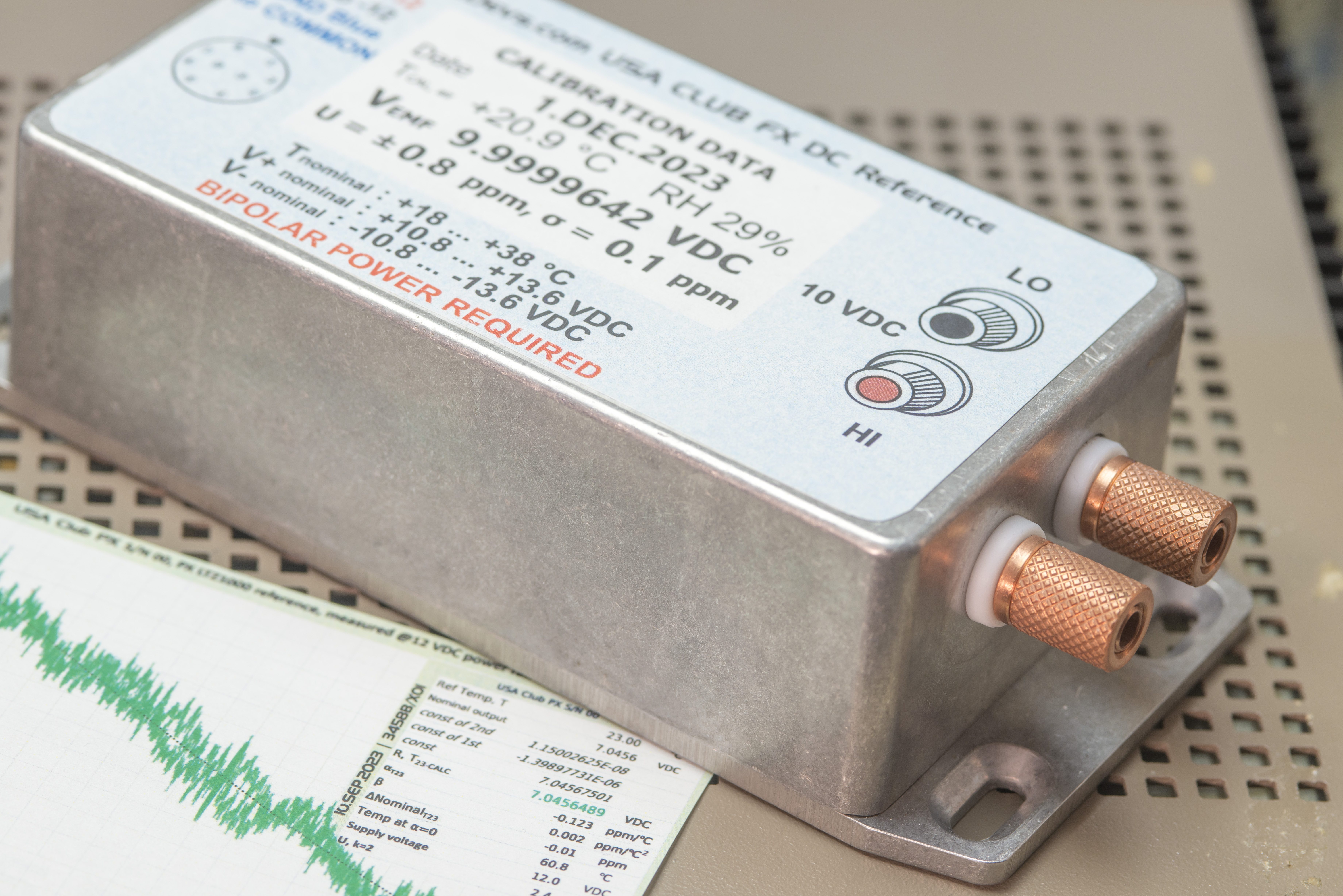
Final value of USA Club, as shipped.
And now final dataset with xDevs.com voltage array reference shown in cross blue marks.
This gives final value for FX 10V output at +9.9999642 V with uncertainty ±0.8 µV/V. Hopefully it will serve the next round well and come back for recalibration no earlier than 2025.
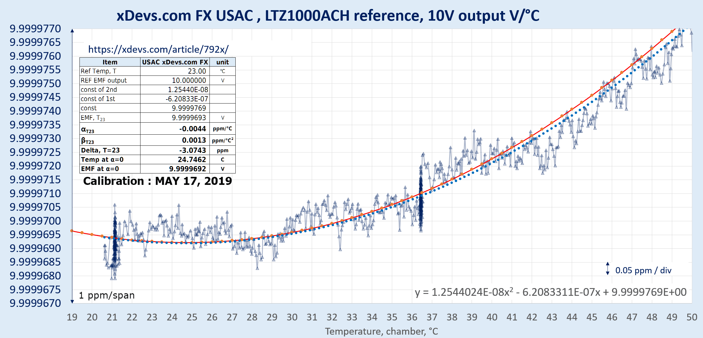
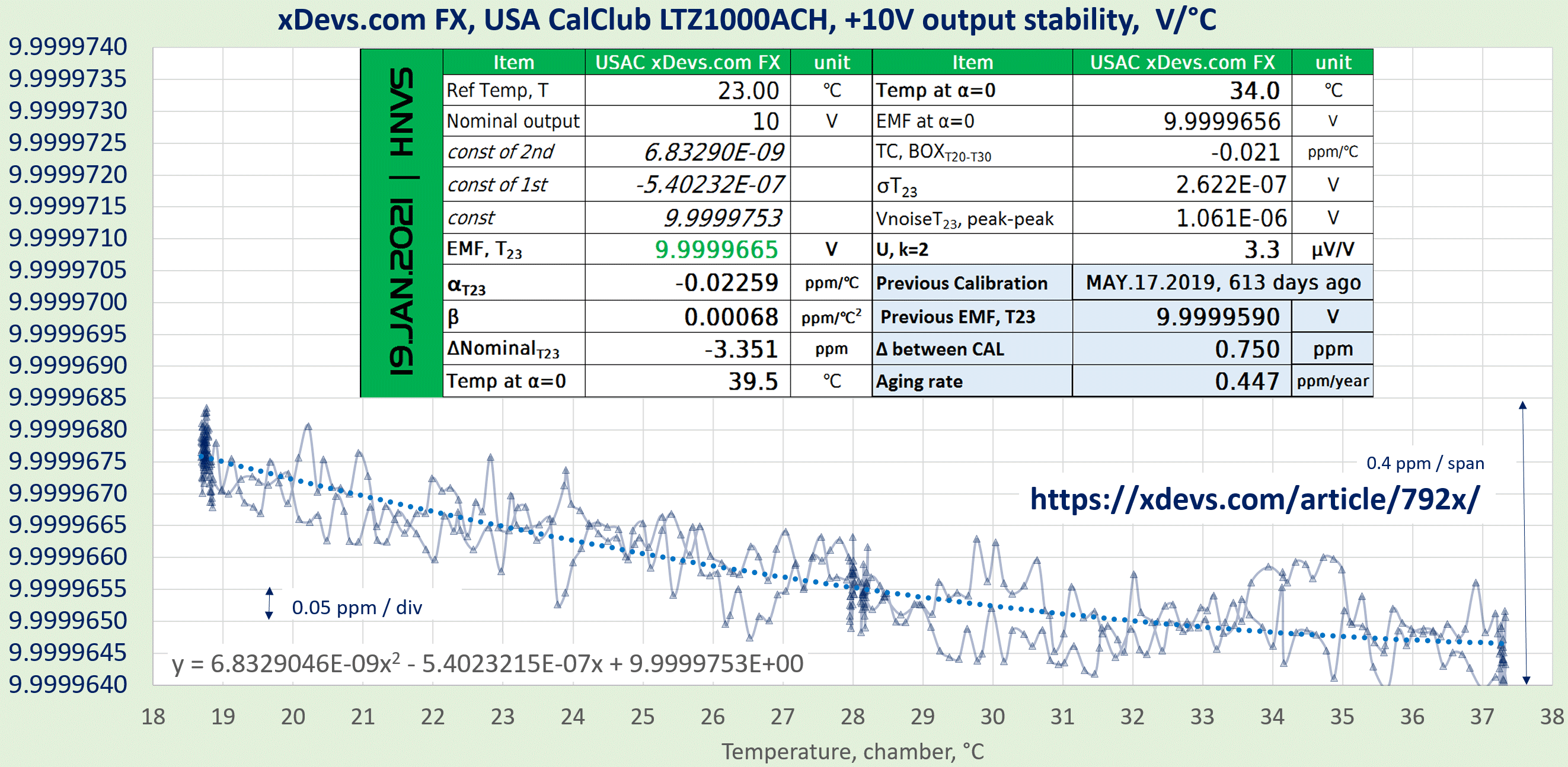
Temperature coefficient of this USA Club FX reference
Verification of temperature stability was not retested for FX reference this time. As test sweep in January 2023 revealed it wasn’t changed from previous data. So here I just reiterate results obtained during January 2023 verification with calculated coefficients are α = -0.0242 µV/V/°C and negligible β = +0.0003 µV/V/°C2 with sweet spot temperature +69.6 °C.
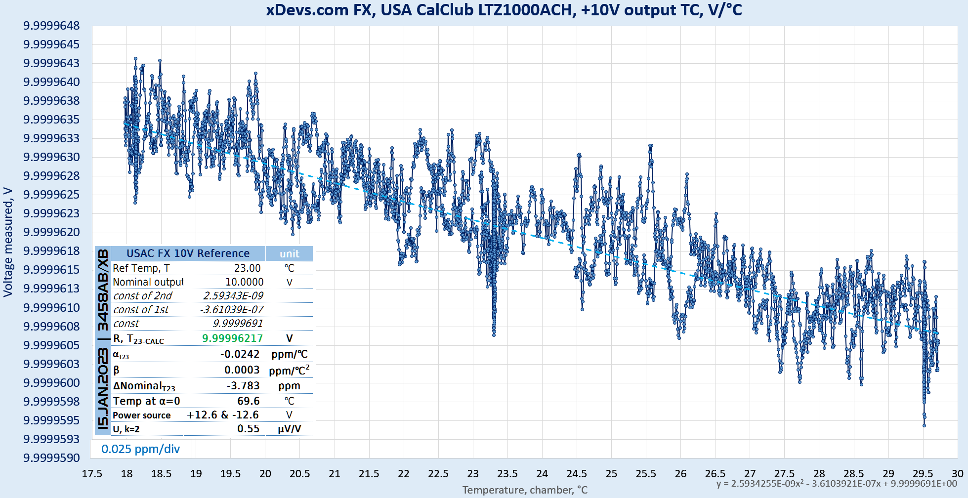
Image 35: Temperature coefficient calibration on xDevs.com FX USAC unit, from +18 °C to +29.5 °C
Bonus calibration – PX raw LTZ1000A reference
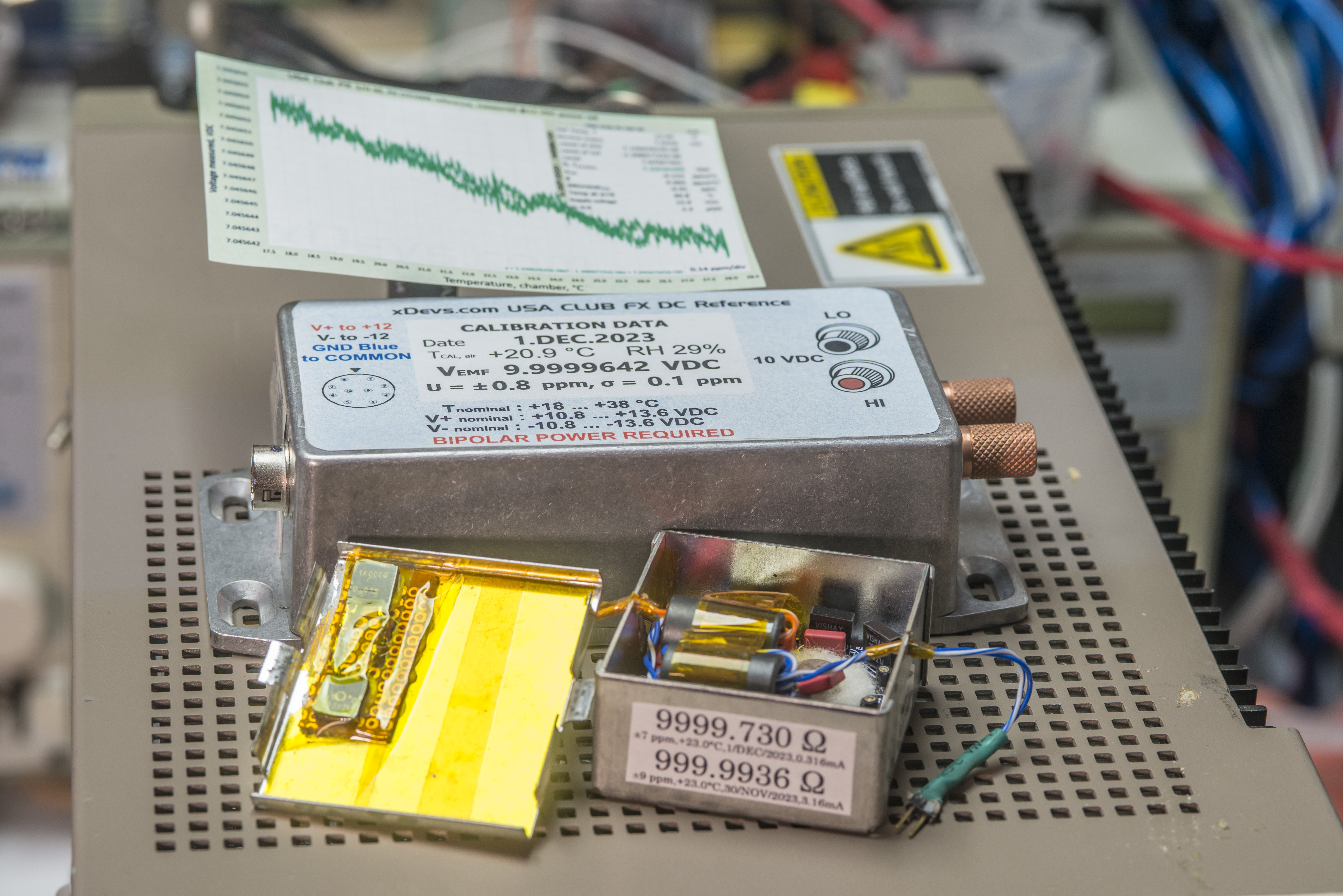
This time I also received other bits in the kit package. I had few 3458A in the lab idle and hooked up these devices for free calibration as well. Wiring was quite a challenge because all lab setup is designed around low thermal spade lug use with shielded cabling and was not ready for banana connectors and sockets stuff in the kit.
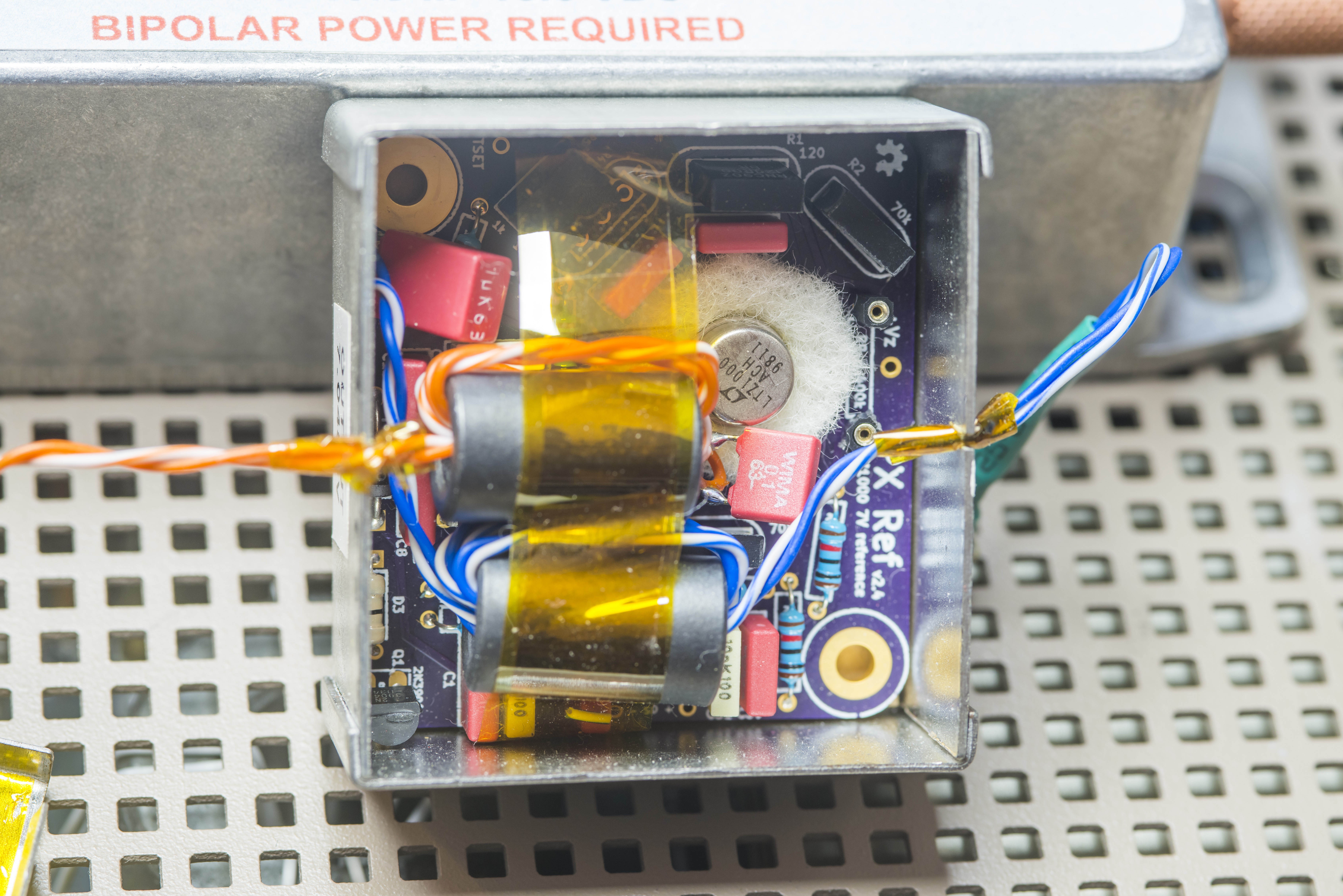
Direct LTZ1000A zener reference implemented with open-source public PX PCBA design. Careful reveal under the lid shows us old LTZ1000ACH chip, manufactured on 11th week 1998, some WIMA film capacitors around and black epoxy RNC90Z BMF resistors to set operation points for zener chip.
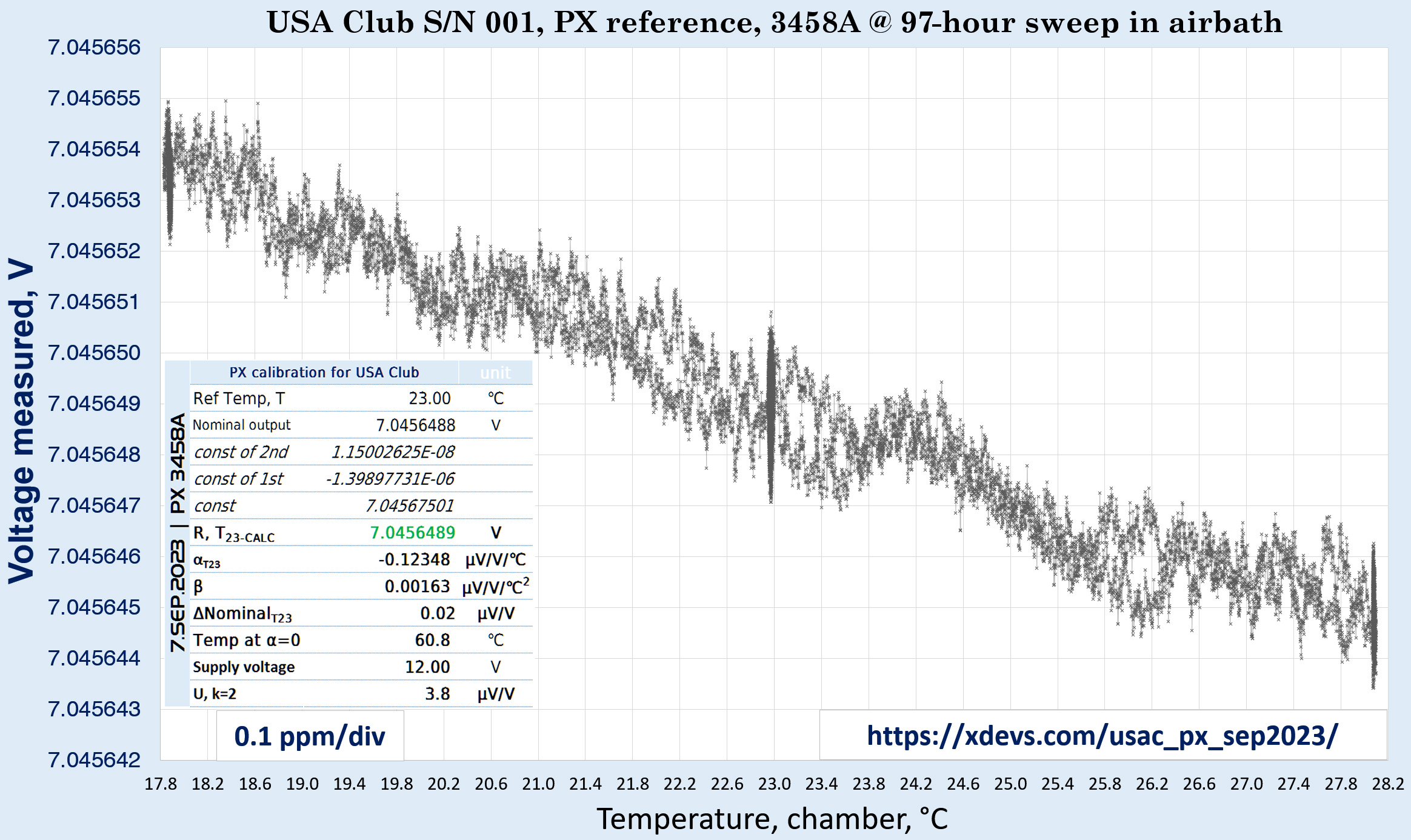
For calibration PX placed in airbath and connected to the Keithley 2400 SMU configured to source +12.0 VDC with 100 mA compliance limit. Output was measured by Keysight 3458A while temperature slowly ramped up and down. Test sweep performed in 97 hours step between September 6 2023 and September 10 2023. RAW-data file and live time-scales plot is as usual available on xDevs page if you click on the chart above. Results of this calibration produced temperature coefficients α = -0.124 µV/V/°C and negligible β = +0.0016 µV/V/°C2 with sweet spot temperature +60.8 °C when α change sign.
This conclude PX output calibration with 7.0456489 V output voltage at +23.0 °C temperature with uncertainty of the measurement ±1.9 µV/V.
Bonus calibration – 1kΩ S102K
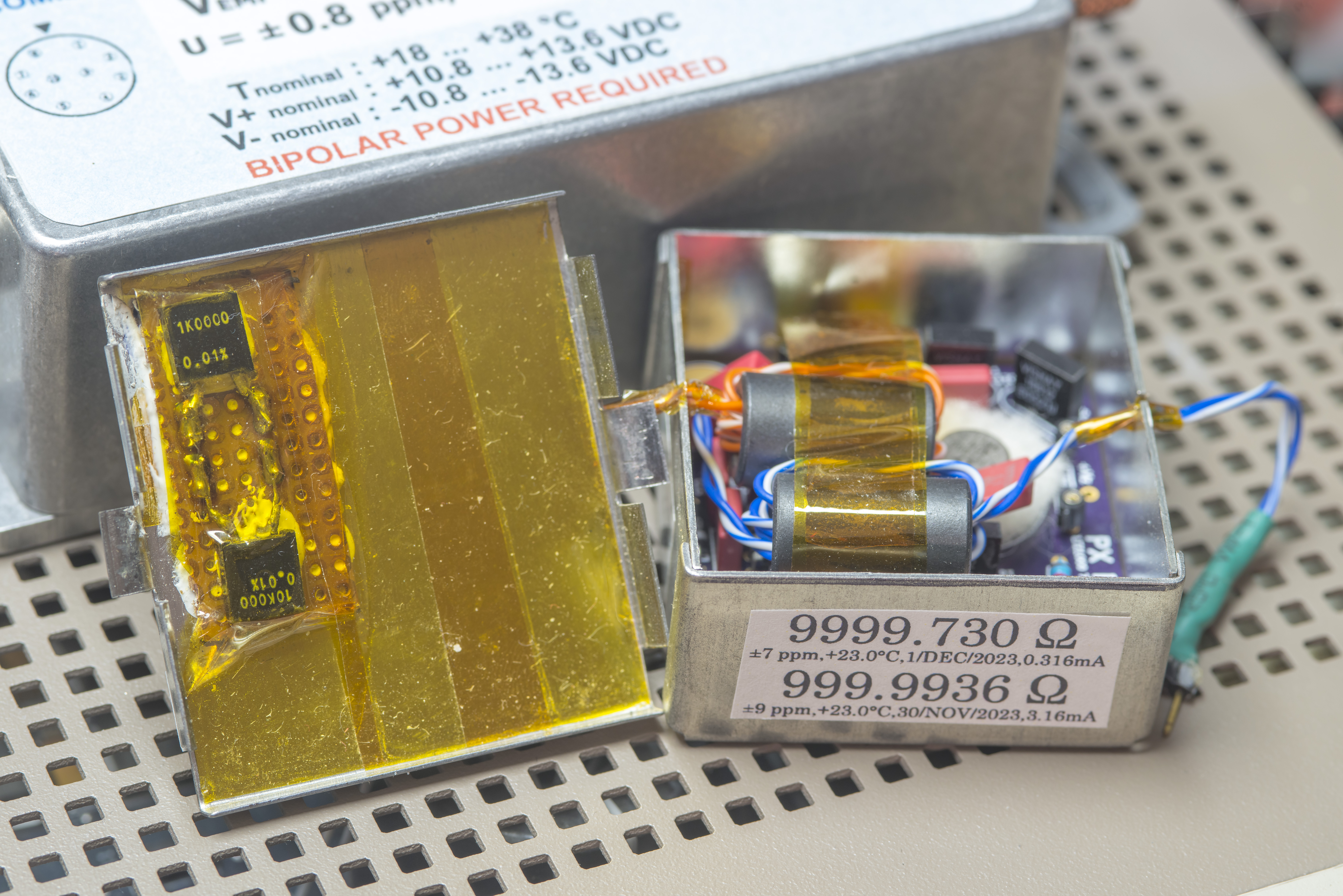
Same box with PX LTZ1000A-based reference contained a side bodge with two BMF S102-style resistors, taped to the lid with kapton tape and some kind of white epoxy, perhaps thermal paste. Each resistor leg terminated to pair of contacts from standard DIP-8 collect socket, exposed externally.
Both resistors rated with 0.01% specification, based from marking.
Relationship between resistance measurement of elements and air-bath temperature sensor placed next to PX box is plotted on a chart:
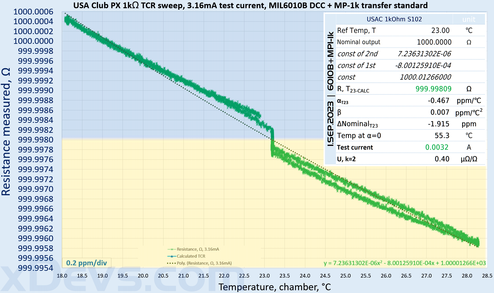
Resistors were measured with MI 6010B DCC bridge against fixed standard in a separate air-bath. Resistance measurements were done multiple times and large resistance shift was observed in between the runs. Perhaps it was caused by questionable connections and cabling adapters, as there is no way for good low-thermal connection to resistor elements in PX. Results of this calibration produced temperature coefficients with test current 3.16 mA : α = -0.467 µΩ/Ω/°C and negligible β = +0.007 µΩ/Ω/°C2 with sweet spot temperature +55.3 °C when α change sign.
This conclude PX output calibration for 1 kΩ at 999.9936 Ω at +23.0 °C temperature with uncertainty of the measurement ±9 µΩ/Ω.
Bonus calibration – 10 kΩ S102K
test1
test-ref – MP1 verification
test2
Time series dataset with multiple different axis and charts might be confusing at first, hence separate chart with resistance to airbath temperature relation is presented below.
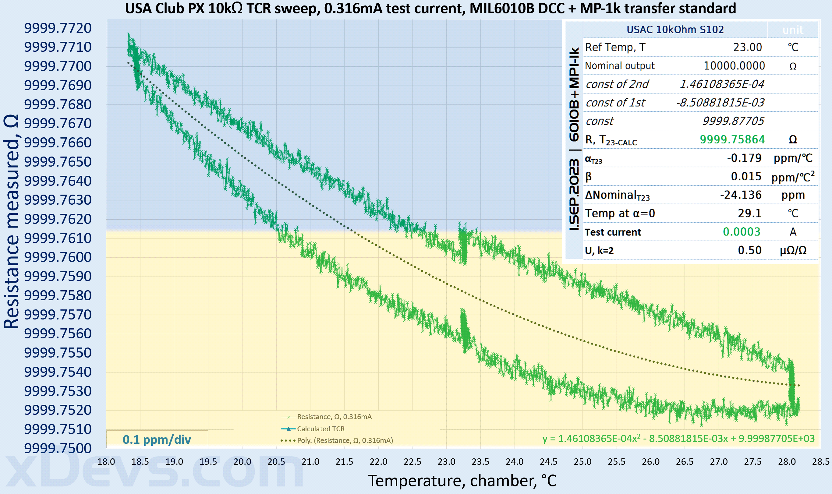
Resistors were measured with MI 6010B DCC bridge against fixed standard in a separate air-bath. Resistance measurements were done multiple times and large resistance shift was observed in between the runs. Perhaps it was caused by questionable connections and cabling adapters, as there is no way for good low-thermal connection to resistor elements in PX. Results of this calibration produced temperature coefficients with test current 0.316 mA : α = -0.179 µΩ/Ω/°C and negligible β = +0.015 µΩ/Ω/°C2 with sweet spot temperature +29.1 °C when α change sign.
This conclude PX output calibration for 10 kΩ at 9999.730 Ω at +23.0 °C temperature with large uncertainty of the measurement ±7 µΩ/Ω.
USA Club kit as shipped and conclusion
In the end FX device and rest of USA Club kit bits were shipped back in December 2023, and hopefully it will continue to rotate between members without further incidents. Sure, we got now some increased uncertainty after physical change with FX, and some difficult to explain small scale drift.
But taking a step back and remembering actual purpose and use case for USA Club transfers, such instability would be still pretty much way below the instruments own uncertainties of the participants labs. Even freshly adjusted and calibrated 3458A DMM would only have ±3.6 µV/V uncertainty for 10 V point on 90 days period, about a magnitude worse to uncertainty assigned to FX, including the voltage change.
S102 resistors on the other hand are not as good to fully judge quality of 6½ or longer resolution DMM stability. Even over the short period of one month between measurements output was changed quite a lot. Exposed epoxy package, connection scheme with complicated collets and unstable connections to resistors as result is not really adequate to ensure long-term uncertainty below ±10 µΩ/Ω.
Calibration values are determined by median readings of 24 hour window. They are wriiten as 8 digit values from math calculations but the actual uncertainties are wider than 8th digit due to limitations of the zener noise, measurements setup, temperature and pressure contributions and all other errors. Best calibration services in commercial laboratories usually provide 10V measurements uncertainties at 0.1 to 0.4 µV/V levels, valid only during the time of measurement. So use these values with this understanding in mind. With travel kit reference like USA Club recovery of output is also possible error contributor, since reference has no battery backup and only shipped cold.
Summary with results of USA Club kit as shipped provided in table below.
| Model and serial | Calibration date | Assigned value | Uncertainty | α | β | ZTC |
|---|---|---|---|---|---|---|
| USA Club FX 10 V | 17.MAY.2019 | 9.9999693 V | ± 2.5 µV/V | -0.0044 µV/V/K | +0.0001 µV/V/°K2 | +24.7 °C |
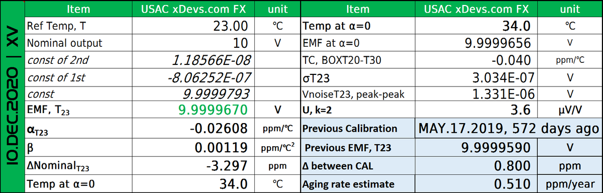
| USA Club FX 10 V | 10.DEC.2020 | 9.9999670 V | ± 1.8 µV/V | -0.026 µV/V/K | +0.0001 µV/V/°K2 | +34.0 °C |
| USA Club FX 10 V | 19.JAN.2021 | 9.9999665 V | ± 1.7 µV/V | -0.023 µV/V/K | +0.0007 µV/V/°K2 | +39.5 °C |
| USA Club FX 10 V | 15.JAN.2023 | 9.99996217 V | ± 0.6 µV/V | -0.024 µV/V/K | +0.0003 µV/V/°K2 | +69.6 °C |
| USA Club FX 10 V | 23.NOV.2023 | 9.99996332 V | ± 0.8 µV/V | Not tested | Not tested | Not tested |
| USA Club FX 10 V | 1.DEC.2023 | 9.9999642 V | ± 0.8 µV/V | Not tested | Not tested | Not tested |
| USA Club PX 7 V | 7.SEP.2023 | 7.0456489 V | ± 1.9 µV/V | -0.123 µV/V/K | +0.0016 µV/V/°K2 | +60.8 °C |
| USA Club PX 1 kΩ | 30.NOV.2023 | 999.9936 Ω | ± 7 µΩ/Ω | -0.467 µΩ/Ω/K | +0.007 µΩ/Ω/°K2 | +55.3 °C |
| USA Club FX 10 kΩ | 1.DEC.2023 | 9999.730 Ω | ± 9 µΩ/Ω | -0.179 µΩ/Ω/K | +0.015 µΩ/Ω/°K2 | +29.1 °C |
Discussion about this article and related stuff is very welcome in comment section or at our own IRC-chat server: irc.xdevs.com (port 6010, channel: #xDevs.com) or via email contact.
Projects like this are born from passion and a desire to share how things work. Education is the foundation of a healthy society - especially important in today's volatile world. xDevs began as a personal project notepad in Kherson, Ukraine back in 2008 and has grown with support of passionate readers just like you. There are no (and never will be) any ads, sponsors or shareholders behind xDevs.com, just a commitment to inspire and help learning. If you are in a position to help others like us, please consider supporting xDevs.com’s home-country Ukraine in its defense of freedom to speak, freedom to live in peace and freedom to choose their way. You can use official site to support Ukraine – United24 or Help99. Every cent counts.
Modified: Feb. 18, 2024, 10:24 p.m.