Contents
- Intro
- Disclaimer
- Project concept
- Fluke 792A Power Pack repair
- Schematics for the reference
- Board layout process
- Two weeks later, assembly and initial bring-up
- PCB layout and shielded enclosure
- Parts source and final assembly
- Initial test
- Thermal images
- Front panel and guard shield modify to add binding posts for 10V output
- Digital ID function
- Build 10 units for EEVBlog community
- FX status log
- Final assembled reference, ready for use as working standard
- Calibration results and performance tracking
- Cable assembly for 792A use
- Summary
![]()
![]()
![]()
![]()
![]()
![]()
Intro
Regular xDevs.com readers already know about number of laboratory grade instruments that are repaired or tested in last few years. My KX LTZ1000-based reference got repeated by analog design enthusiasts and discussed in lengths on EEVBlog forum, to my great surprise. I never meant to see such an interest in very expensive and niche application device. This is even recognized in the name, KX stands for Keithley-meter eXperiment reference, as back when I started the design I wanted to attempt for Keithley 2001 DMM reference stability improvement. That’s why module provide only direct +7.xxxx V, does not have any additional protection or onboard pre-regulators and fits compact PCB, that may be hard to hand assemble.
Fast forward to 2018, more than 100 (!) PCBs were produced by the community, with only about 10 my own modules. I’d like to thank all of the followers for their effort on sharing their measurements and results. Few highlights are collected in table 1 just to recognize some of the modules.
| Member | Board photo | Voltage | Member | Board photo | Voltage |
|---|---|---|---|---|---|
| BFX | 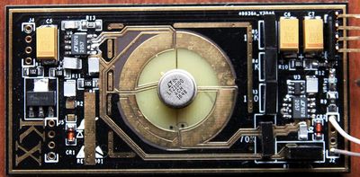 |
+7.13555 V, 34401A | SvanGool | 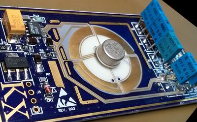 |
|
| hwj-d | 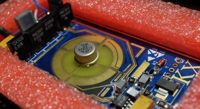 |
+7.16262 V, 34461A | mimmus78 | 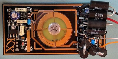 |
+7.133666, 3458A |
| kj7e | 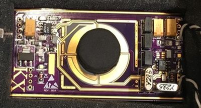 |
+7.14150 V, 34465A | sergioag | 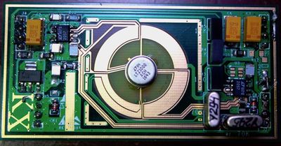 |
|
| VK5RC | 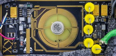 |
+7.134056, 3458A | dr.diesel | 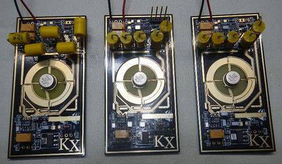 |
+7.139354, 7510 |
Table 1: xDevs.com KX reference builds from different members
And of course none of this would happen without great support:
- Todd for patience and continous support with calibrations and verifications to traceable Fluke DC standards.
- Dr.Frank for valuable feedback and inspiration.
- Kleinstein for countless reviews and design suggestions.
- Keysight Technology for keeping 3458A’s alive all these years.
- Linear Technology for making top-level “Renez-Repus” reference available on the market and dedication to high levels of analog performance.
So what is this project about? It’s another reference design, but this time more complete and ready for practical use in the lab, providing cardinal +10.0000 VDC point, based off LTZ1000A core. Upscaling stable but arbitrary +7.xxxxxx voltage to calibrated +10.00000 V output to ppm-level accuracy is a task on it’s own, even more difficult so.
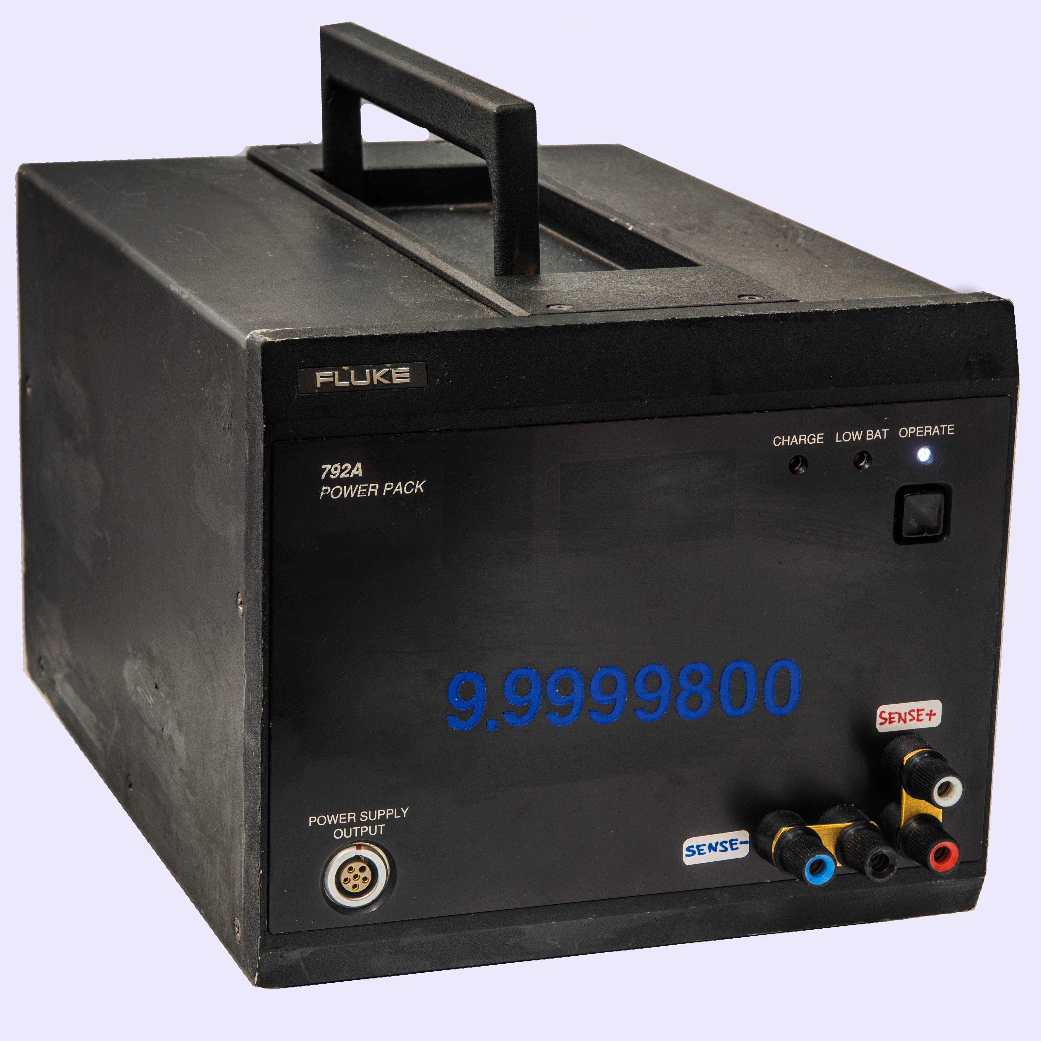
Too bootstrap the project and not to spend too much time on important, but secondary engineering items, existing commercial power pack will be used. And for that role Fluke 792A Power Pack will fit perfectly. This assembly based around four 6V SLA-type battery packs, providing internal unregulated bipolar voltage supply +/-12 VDC and regulated +/-11 VDC output externally. Battery pack has mains transformer and standard IEC power input circuitry, onboard charger to maintain battery capacity and LED indicators for status. Massive inner shielding also provided to protect internal circuitry from external RFI/EMI.
So idea is to build custom LTZ1000A-reference, add 7V-10V circuit to it, and put everything into Flule 792A Power pack. Sounds simple enough, let’s get started.
Disclaimer
All information posted here is hosted just for education purposes and provided AS IS. In no event shall the author, xDevs.com site, or any other 3rd party, including Fluke or LTC be liable for any special, direct, indirect, or consequential damages or any damages whatsoever resulting from loss of use, data or profits, whether in an action of contract, negligence or other action, arising out of or in connection with the use or performance of information published here.
Redistribution and use of this article or any files referenced in it, in source and binary forms, with or without modification, are permitted provided that the following conditions are met:
- Redistribution of article must retain the above copyright notice, this list of conditions, link to this page (https://xdevs.com/article/792x/) and the following disclaimer.
- Redistribution of files in binary form must reproduce the above copyright notice, this list of conditions, link to this page (https://xdevs.com/article/792x/), and the following disclaimer in the documentation and/or other materials provided with the distribution, for example Readme file.
If you willing to contribute or add your experience regarding your voltage reference design or provide any extra information, such as test results, experiment setup photographs, you can do so following these simple instructions. We also welcome related discussion at our own IRC channel or forum.
Project concept
Actually all started once I bought dead Fluke 792A power pack (without anything else). First thought was to simply fix it and use as floating power source for lab use, but then it would become just an expensive and bulky power supply, without much of other use.
From Todd’s 792A article we already learned about internal design of the power pack, and availability of extra room inside the shield, just enough to fit compact voltage reference. As I don’t have “real deal”, Fluke 732A/B DC voltage standard, I’ve decided make this project in attempt to achieve similar end result, albeit at larger footprint.
Also target goal is to preserve original functionality of 792A Power Pack so it can be used to power the 792A AC/DC Transfer Standard as well, in case such need arise.
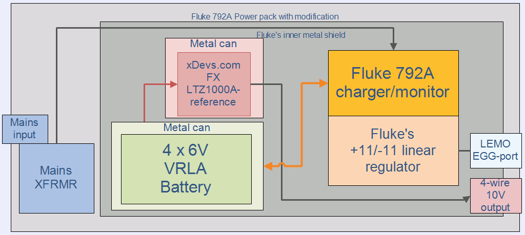
Image 1: xDevs.com FX DC voltage reference concept
So this is how Fluke eXperimental battery-backed DC voltage refence project started.
Together with prototype Fluke SL935 ovenized 1 Ω/10 KΩ resistance standard these two boxes would be handy tool to maintain calibration checks and transfers for Keysight 3458A and Fluke 5700A multifunction calibrator.
Fluke 792A Power Pack repair
But first we need to inspect 792A power pack and repair it, so it can be functional again per it’s original purpose.
Schematics for the reference module, xDevs.com FX
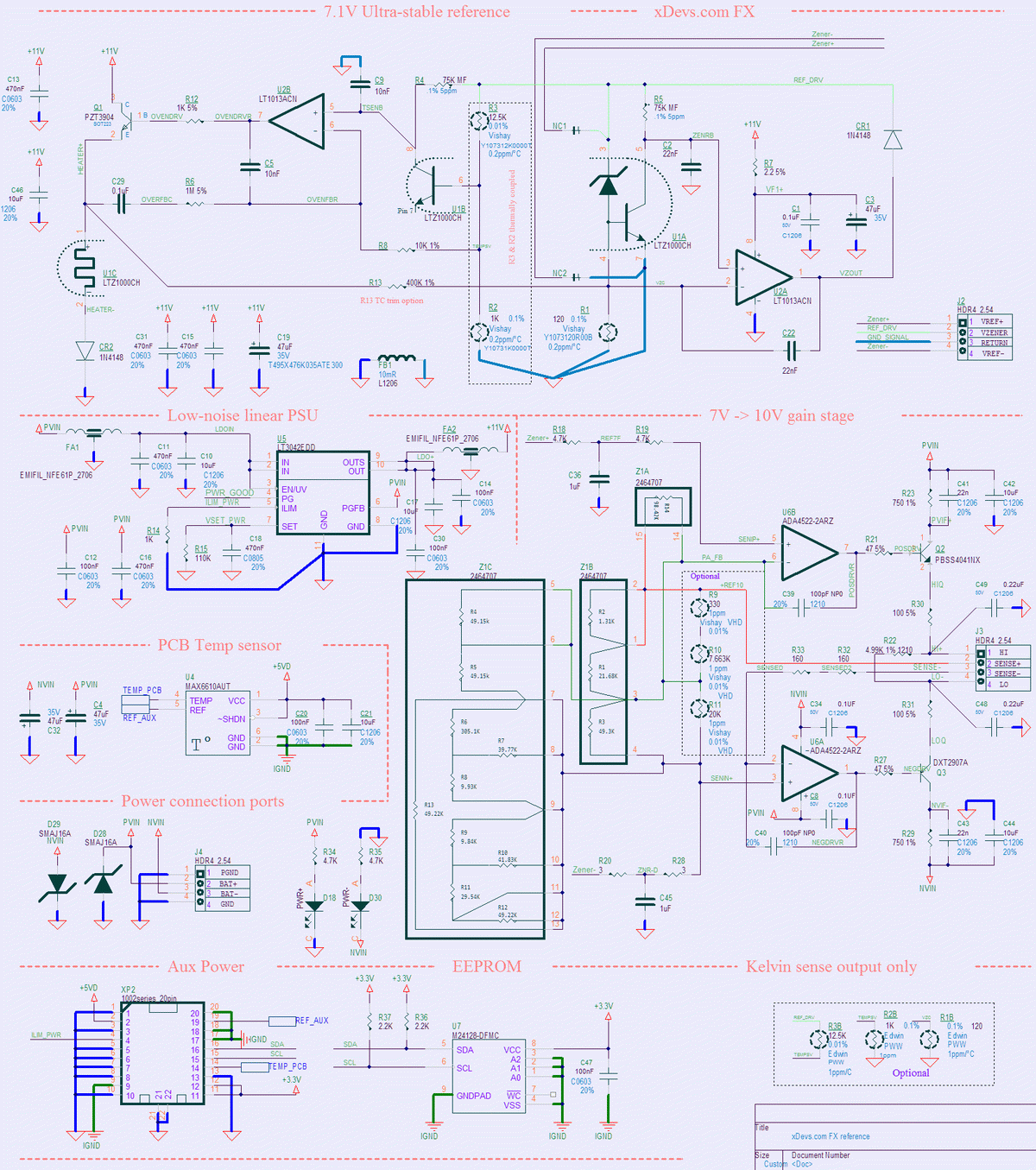
Image 2: xDevs.com FX DC voltage reference schematics
Zener reference itself is standard LTZ1000A circuit, well known and tested by many people. There is no reason to change anything in it, really, as it works great and performance limited to the quality of the LTZ1000 chip itself and long-term stability of the used resistors.
Oven temperature is selected at +60 °C point, by using 12.5 KΩ and 1KΩ resistor network R3+R2. Opamp is traditional Linear LT1013 in DIP-8 package. SMD parts are less preferred for high precision application due to possibility of board stress coupling from the PCB.
Direct 7V output from the reference available on the test header J2, following kelvin-connection technique.
FB1,FB3 junctions are stuffed for easier routing, to connect power and signal grounds in single point at the board output.
Whole LTZ1000 reference section is powered by low-noise Linear LT3042 regulator U5 in tiny DFN package. SMD Resistor R15 is setting output voltage for the regulator at +11.0 VDC. This is in range of LDO operation when battery is fully charged.
There is also PCB temperature sensor U4 for tweaking and initial debug, using MAXIM MAX6610 temperature sensor in tiny SOT23-5 package.
Now, more critical circuit section is actual 7V to 10V converter.
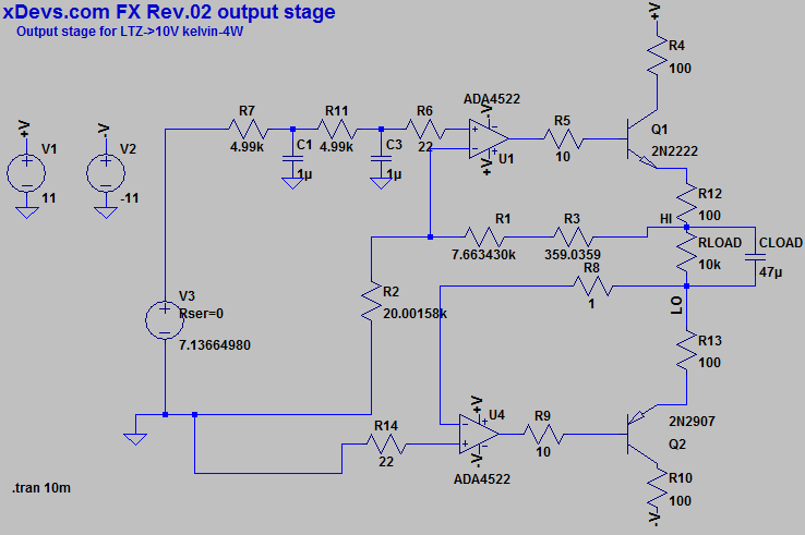
Image 3: xDevs.com FX 10V output amplifier (clickable LTSpice simulation)
Output is driven by precision chopper amplifier Analog Devices ADA4522-2, two sections of which are driving both positive and negative output. Essentially performance and stability of this conversion will be based on the stability of used resistors R1,R2,R3 on LTSpice schematics.
Absolute value of those resistors is not very important, but the ratio between R1 and R2,R3 is crucial. It’s best to select these resistors for equal temperature stability and behaviour, so the total ratio remain as constant as possible even with change of the circuit temperature.
As option, this module also designed around rare Fluke-custom hermetic film resistor network P/N 2464707, taken from Fluke 8846A 6½-digit multimeter. In theory temperature coefficient of each element inherently matched on the network, since it’s manufactured from same material and process and share same ceramic substrate. That should help with equal temperature gradient over both resistor arms.

Image 4: Fluke P/N 2464707 reference/gain precision hermetic resistor
RC network R7C1 and R11C3 also prevent from coupling current noise spikes from chopper amplifier switching back to the LTZ1000A reference output.
Output of both amplifiers driving pair of bipolar transistors to get some current drive capability, as well as protect opamp from dealing with capacitive loads, such as long cables or shielded wiring.
This is perfect example of the circuit that is very hard to accurately simulate, no matter how great simulation software is, so the only way to check it’s performance is to actually breadboard it. I already have my xDevs.com KX LTZ1000 reference ready, so that’s what we will use to get some real-world numbers, before going into full design mode.
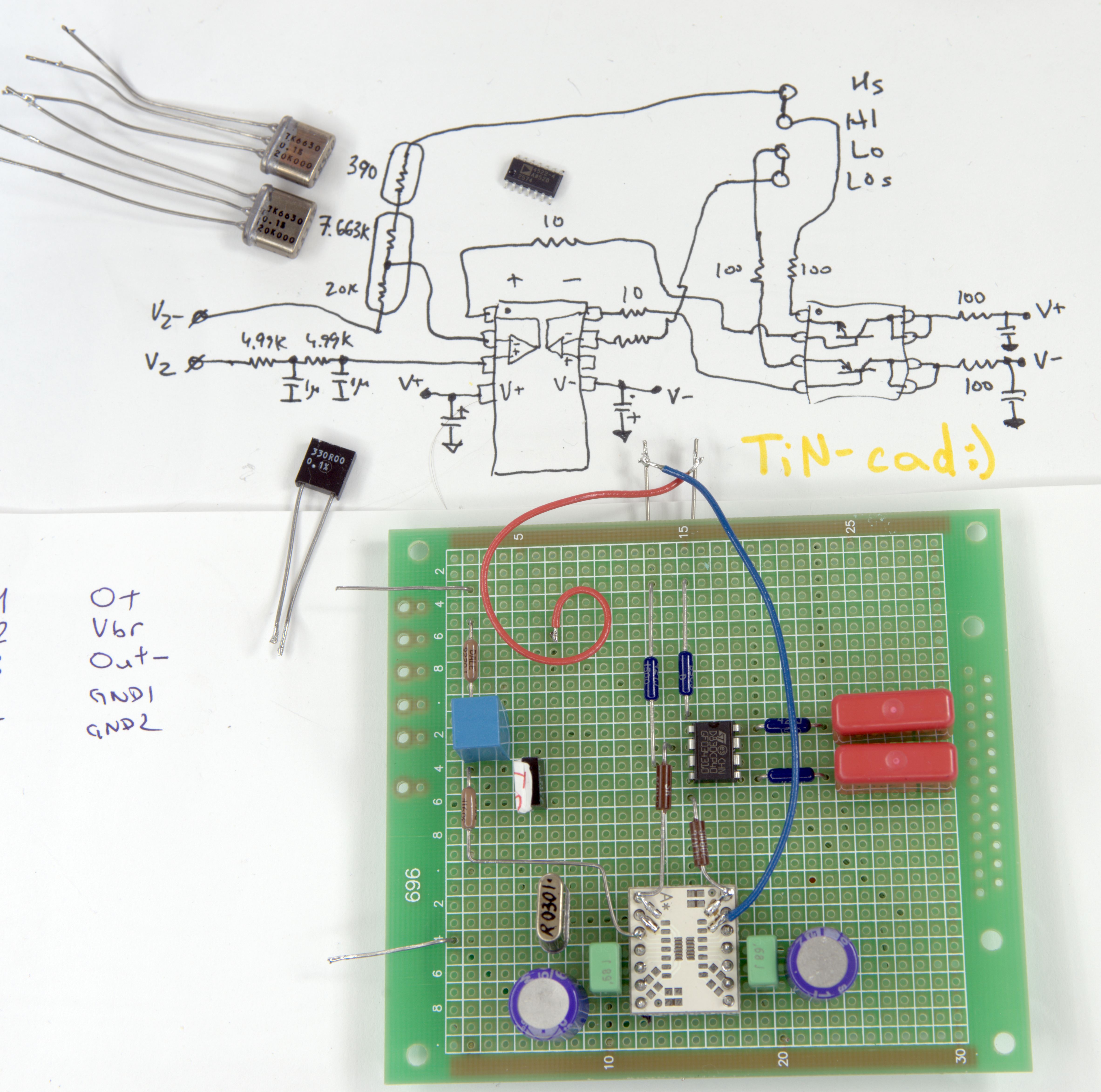
Image 5: xDevs.com FX 10V output amplifier prototype board
After few hours, here’s is the result. I did not have dual version of ADA4522-2, so used ADA4522-4 in SOIC16 package instead. Vishay VHD200 resistor network with values 20.000 KΩ and 7.6630 KΩ together with S102K 330 Ω were used to set the output voltage point. I didn’t spend much effort to trim ideal +10.00000 V as for prototype we don’t care about the output value accuracy.
Output is driven by complementary transistor pair in a single DIP8 package, with marking STD830CP40. Power at the opamp and output transistors is decoupled by few 1 µF MLCCs, few WIMA film capacitors and pair of Sanyo OSCON 150 µF 16V caps (purple cylinders near the opamp).
This prototype is just to verify the correct operation and perform noise and short-term stability test. Calibrated and verified Keysight 3458A 8½-digit DMM was used as a digitizer, together with linux-gpib Raspberry Pi.
Input was connected to the LTZ module output, output of the circuit was connected to the DMM binding posts using pair of CNMC triaxial cables. Whole thing, including the LTZ reference powered from +12 and -12V battery inside Fluke 792A battery pack. So this is pretty close to final design to estimate some stability figures.
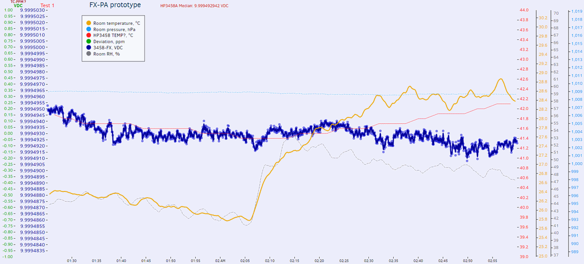
Image 6: xDevs.com FX 10V output amplifier prototype test log
And it worked just as expected. Output voltage remained stable within 0.45 ppm window, which was actually better than expected, as no complete shielding or special care was taken in the test setup assembly. Some data summary presented in Table 1
| Tested parameter | Measured value | Unit |
|---|---|---|
| Output voltage median | +9.9994932 | VDC |
| Output voltage minimum | +9.9994893 | VDC |
| Output voltage maximum | +9.9994942 | VDC |
| Output voltage span (min-max ΔMedian) | 4.9µ (0.49) | VDC (ppm) |
| Short-term 15 minute noise | ±0.5µ (0.1) | VDC (ppm) |
| Temperature stability | better than 0.1 | ppm/°C |
Table 1: Prototype buffer test data
Board layout process
Layout of the PCB was done during streaming on YouTube platform, in three parts.
In part 1 which lasted nearly 6 hours all the main routing was done, few placement adjustment were made and overall board design flow established.
Shorter part 2 continue from where previous video stopped, optimizing design and finetuning the routing. Few schematics changes are implemented:
- Replaced input filter RCR to balanced network using MELF metal film resistors.
- Routed GND_Signal return as point-point signal, no multipoint-connected shapes.
- Rearranged placement for output chopper for more balanced routing
Here’s board layout animation after 2nd video, all 4 layers with 5 second interval. Full resolution GIF available on click.
%(imgref)Image 7: Layout images
And 3rd part with final touches, adding I2C EEPROM for ID and calibration data storage.
Board animation:
Image 8: xDevs.com FX Layout layers
- Added R33 for equal amount of resistors in negative feedback.
- Added optional C48,C49 at the output force
- Redraw schematic symbol and changed trim connections on Fluke resistor network for clarity
- Added power LED D18,D30
- Added I2C U7 EEPROM, for storing module-specific DC output voltage, calibration values, tempco/drift values, configuration parameters, etc.
- Changed connector type to 20pin 0.5mm pitch XP2 for onboard temp sensor and I2C ROM. Power for sensor and ROM are 100% isolated from rest of the reference.
- Added extra C46 cap near heater NPN.
And $420 USD worth of Low Thermal 2758 copper gold-plated connectors:
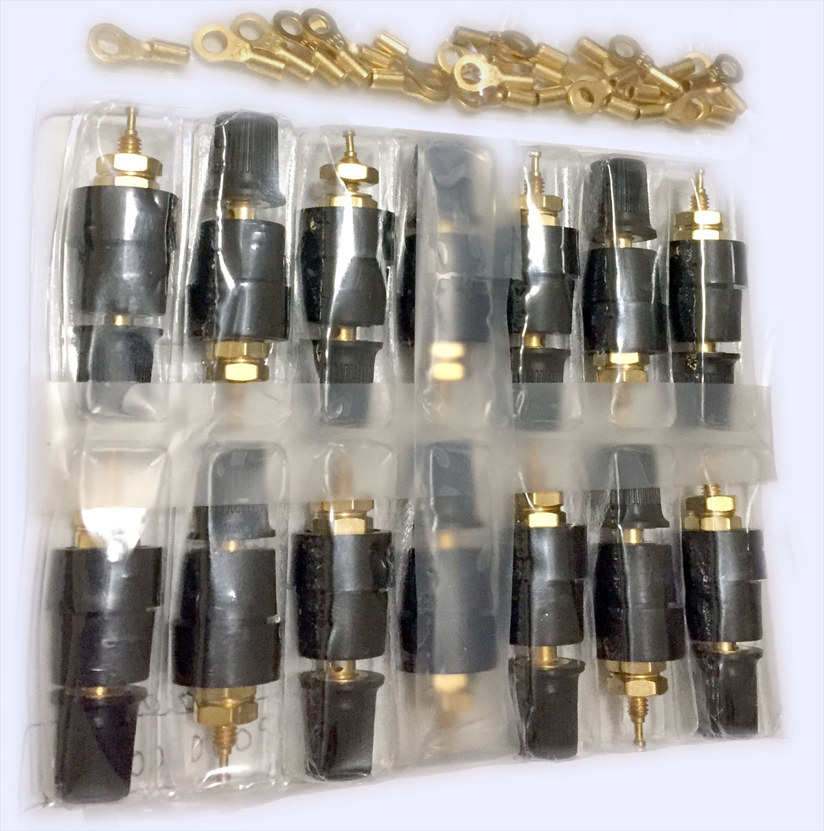
Image 9: Low Thermal binding posts used for F792A battery pack modification
Two weeks later, assembly and initial bring-up
Assembly of the first boards, as received from the PCB house.
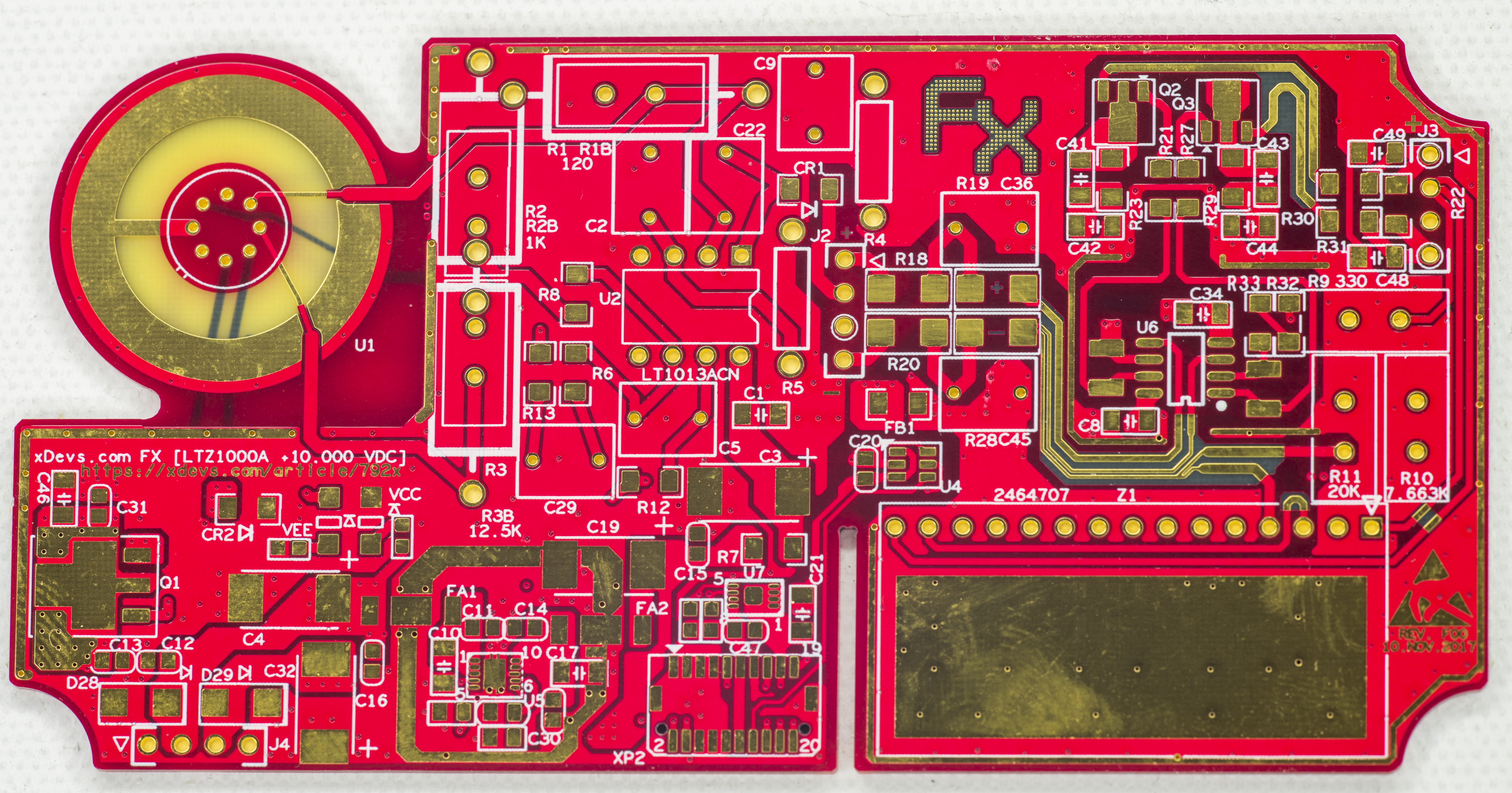

Image 10-11: xDevs.com FX reference top and bottom side
First, comparison to well known HP 3458A A9 DC Reference module and my old KX public version LTZ1000 module.

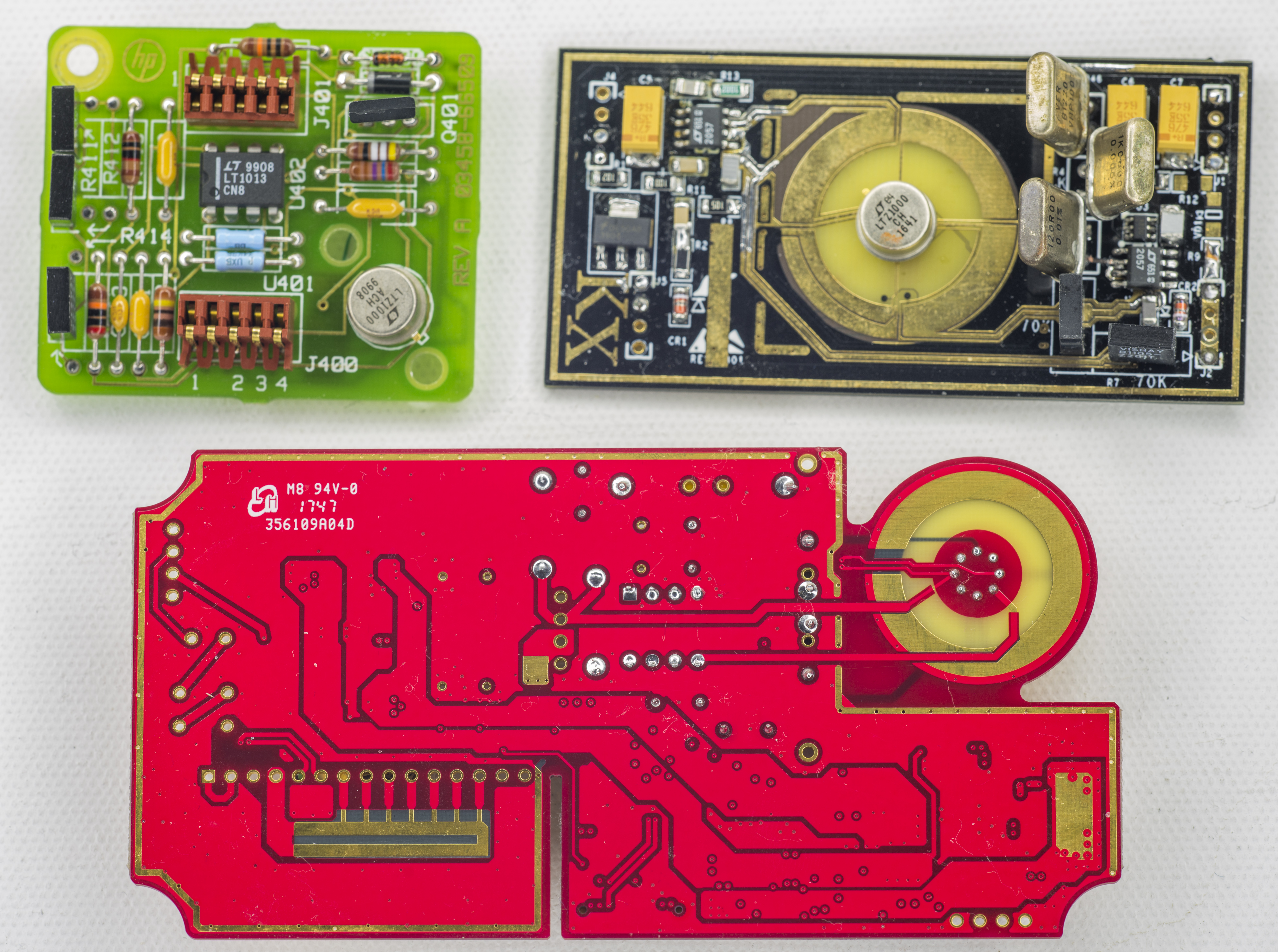
Image 12-13: xDevs.com FX
I’m missing opamp, resistor network and MELF resistors for the 7V->10V output amplifier section, so that will be assembled after parts arrive. Currently I can test tempco and establish intermediate 7V output, and get a glimpse on initial stability, to make sure no funny business happenin.
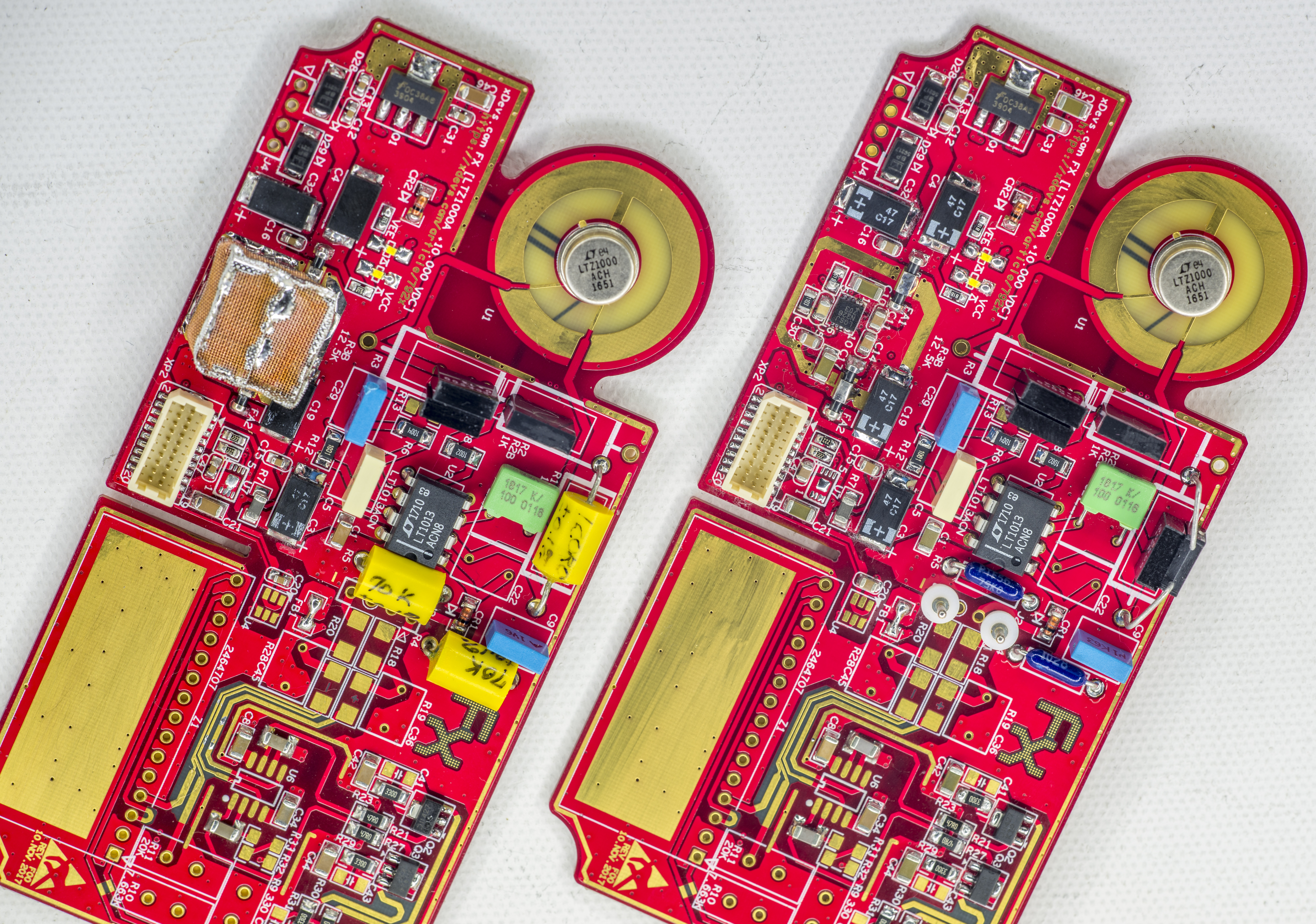
Image 14: xDevs.com FX
Little section with DFN chip is low-noise Linear LT3042 +11V linear regulator, that powers LT1013A and LTZ1000A chip.
Output amp powered directly from input power entry (power source for this module is +12/-12V VRLA battery array).
There are just TVS at the input and few bulk tantalum capacitors.
20-pin connector provide isolated +3.3V to calibration data EEPROM (I2C 24128, U7) and +5V supply to MAX6610 (U4 in center).
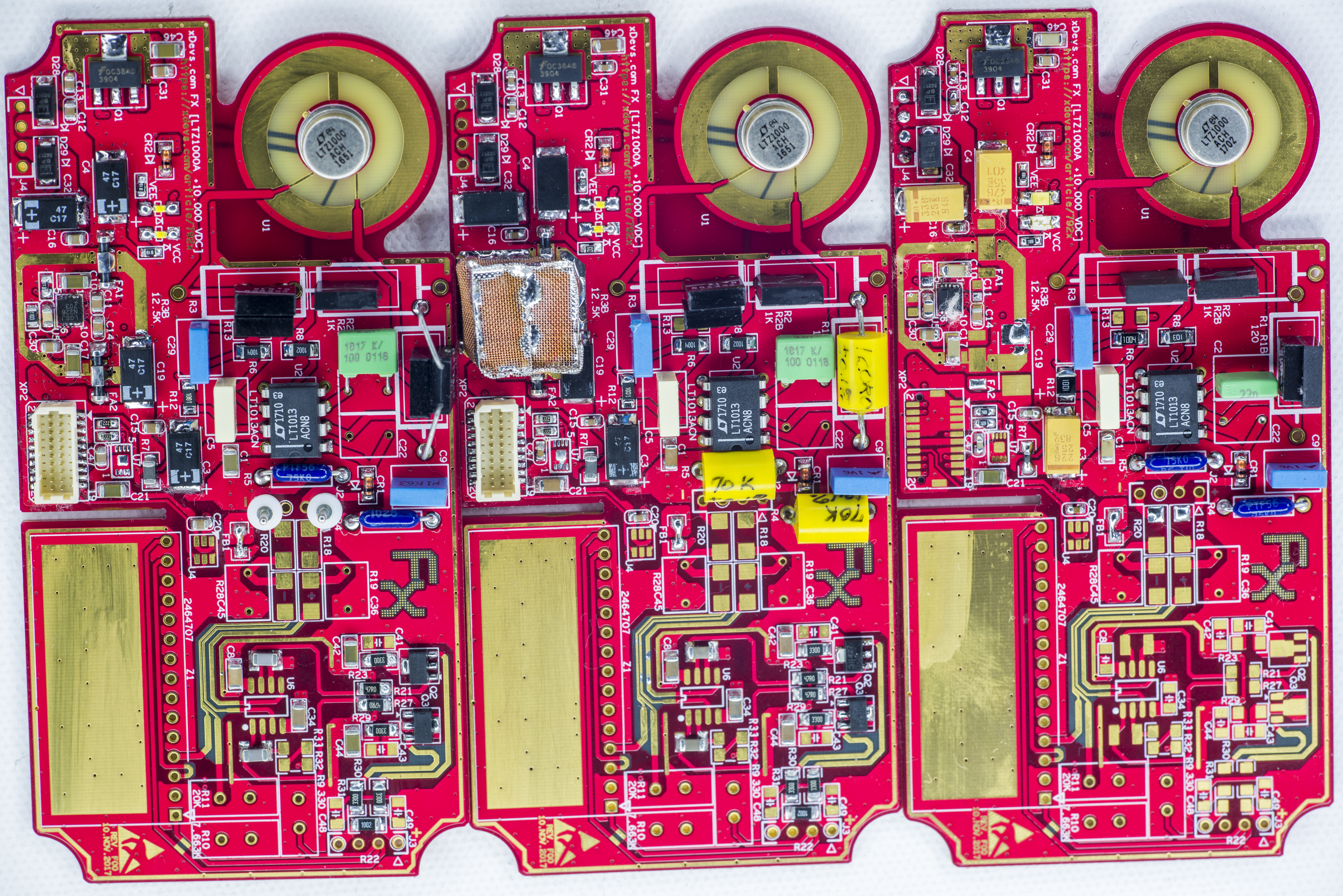
Image 15: Three initial prototype modules
Configurations for first tests (7V section first).
FX 001 : LTZ1000ACH, 51 week 2016, 1K AE YB BMF, 20K S102J + 34.8K S102K, 330R + 300R + 522.2R S102, 2 x PTF56 75K (tested <-6ppm/K).
FX 002 : LTZ1000ACH, 51 week 2016, 1K AE YB BMF, 28.5K S102J + 28.5K S102K, 120R Edwin PWW, 2 x Edwin PWW 70K
FX 003 : LTZ1000ACH, 51 week 2016, 1K AE XB BMF, 15K AE XB BMF, two S102 in parallel to get 132R
First FX001 module running tempco test 1. This test gracefully ramp temperature up to +55 or +50 °C, while keeping ambient room temperature and DMM temperature stable within ±1 °C to establish temperature coefficient on the 7V output.
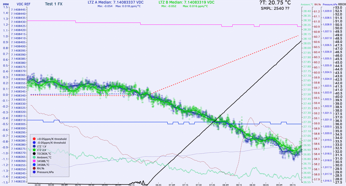
Image 16: First temperature stability in the oven with xDevs.com FX
Both 3458A connected to same output for better confidence. 3458B have math corrected offset +3.3 µV.
Note to change schematics C9 value from 10nF to 100nF.
Second FX002 module running tempco test 1:
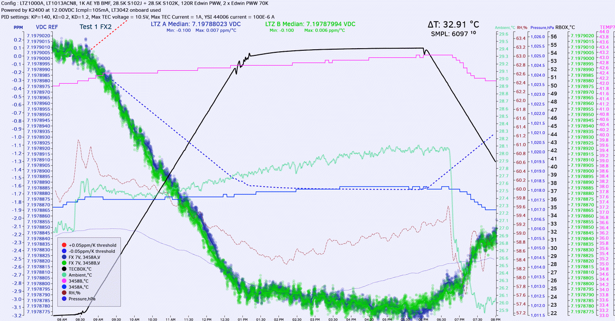
Image 17: Second unit temperature stability in the oven
This module with -0.1 ppm/°C definitely out of desired -0.05 ppm/°C limits for DC Voltage temperature coefficient. Some tweaking will be required.
Third FX003 module running tempco test 1:
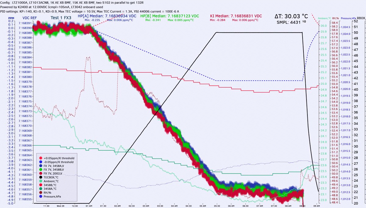
Image 18: Trird unit temperature stability in the oven
This time Keithley 2002 (GPIB 4) was added to voltmeter group. This module with -0.25 ppm/°C is even worse. Some more tweaking will be required.
For Test 2 additional compensation resistor was added, 390KΩ 5% 1206 on R13 position.
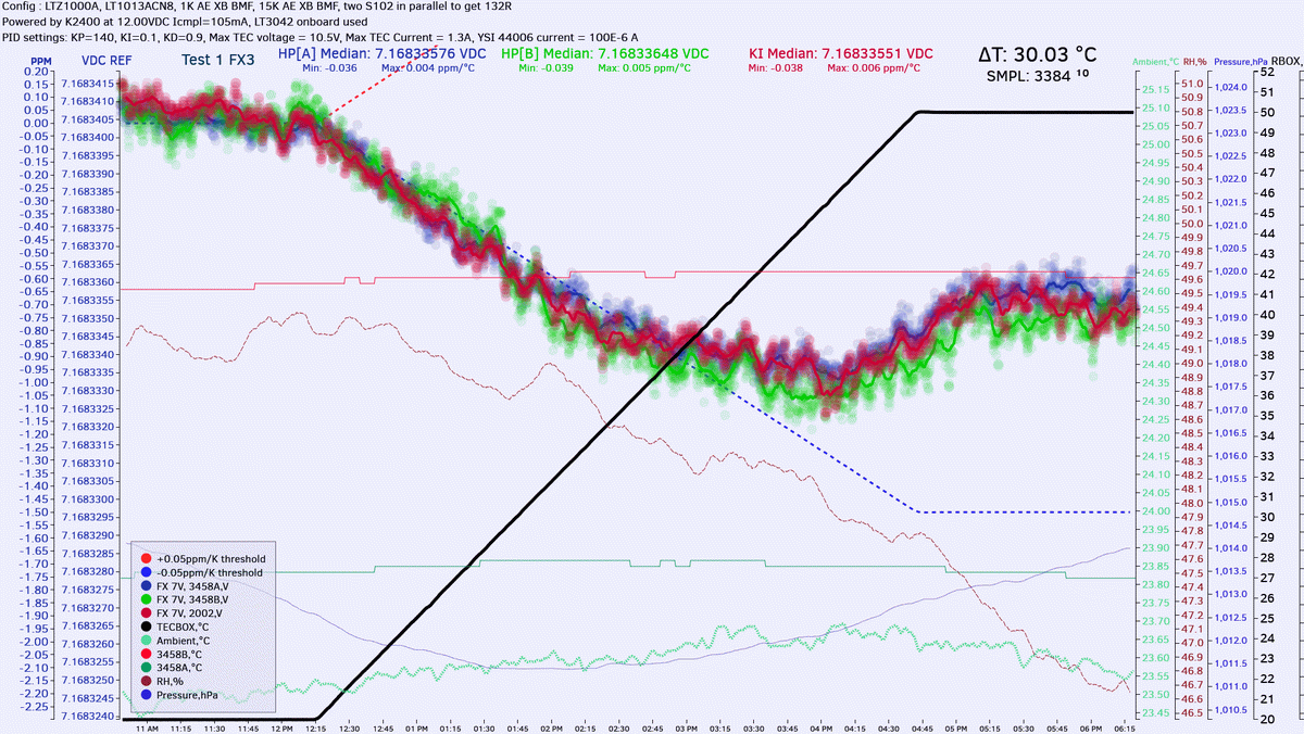
Image 19: Trimming temperature stability with 390KΩ
Much better now! Retest with 331KΩ resistor.
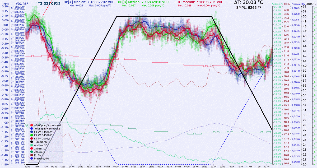
Image 20: Trimming temperature stability with 331KΩ
Now after verification of initial performance of the basic LTZ1000A-reference, we are ready to add 7V -> 10.0000 V section assembly and testing.
Shortly after the video was streamed issue with incorrect voltage was resolved by fixing the mistake with resistor population and first FX3 module delivered stable +9.999960 VDC with 351 Ω trimmer resistor, set by L&N 4754 decade.
Initial testing was performed using Keithley 2182 nanovoltmeter, which is not quite optimal. This is because own noise and stability on 10VDC range of this meter is worse than the actual FX reference performance, so we actually more likely see noise and performance of meter’s own LM399 reference, rather than any figure of the tested LTZ1000A-module.
Testing tempco with output stage
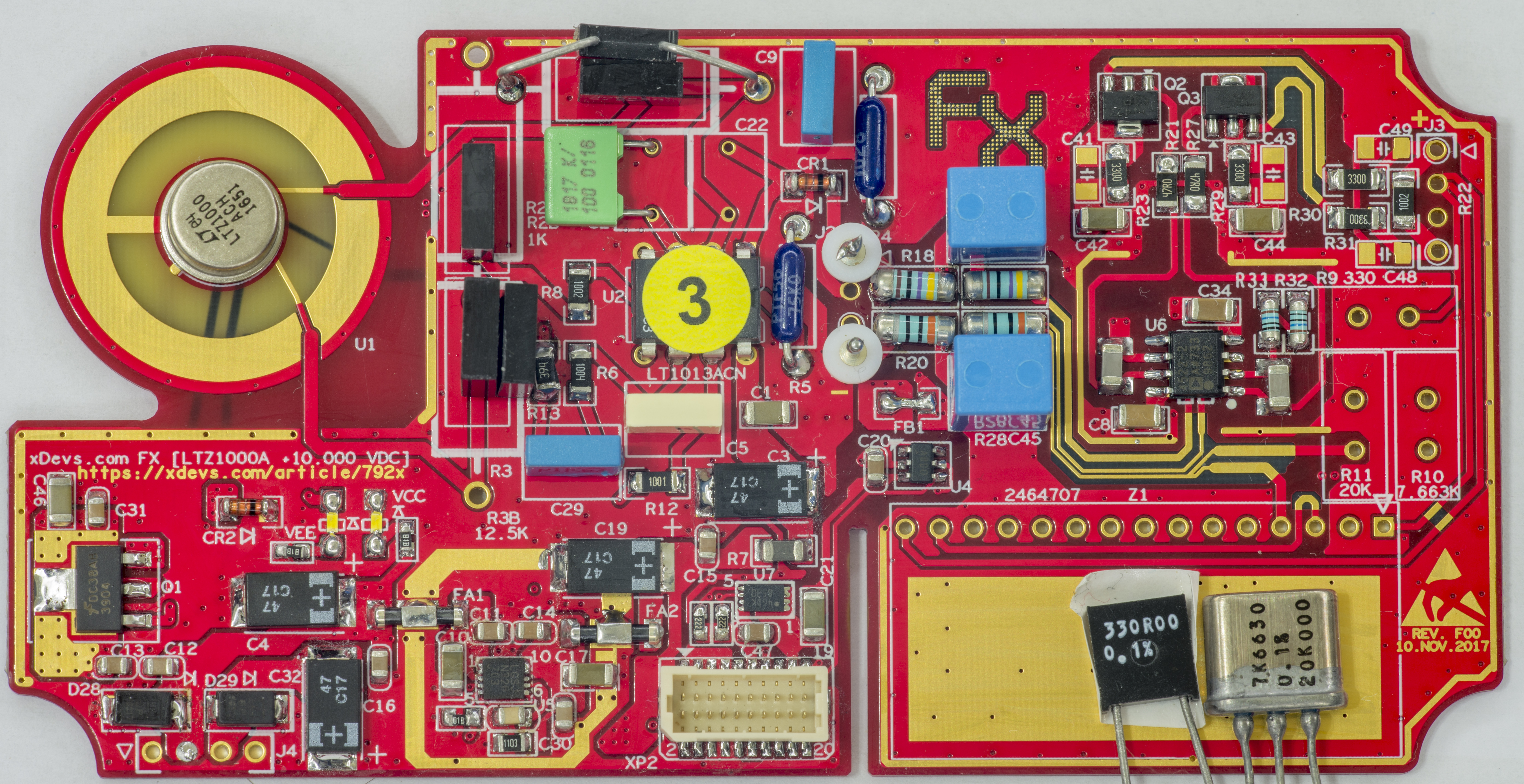
Image 21: Verification for tempco effects by output stage
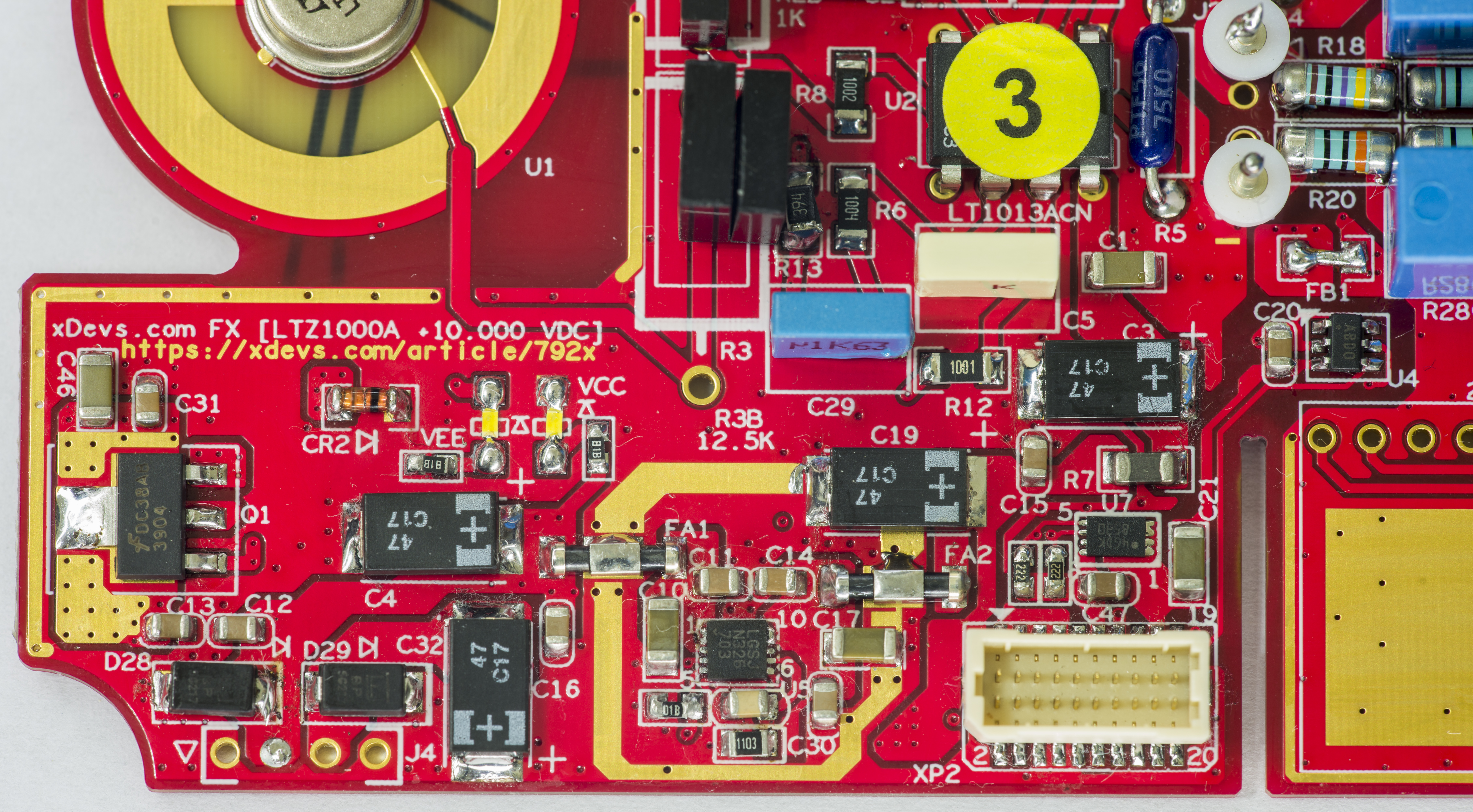

Image 22-23: Output stage stability
Initial testing for tempco started, using 10V output stage.
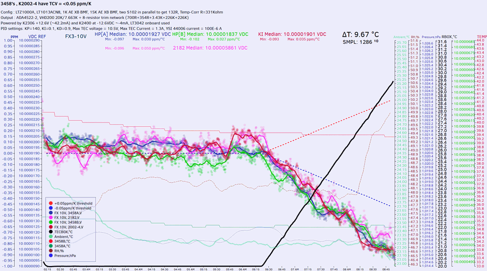
Image 24: Output stage stability test
Trimming with 3458A:
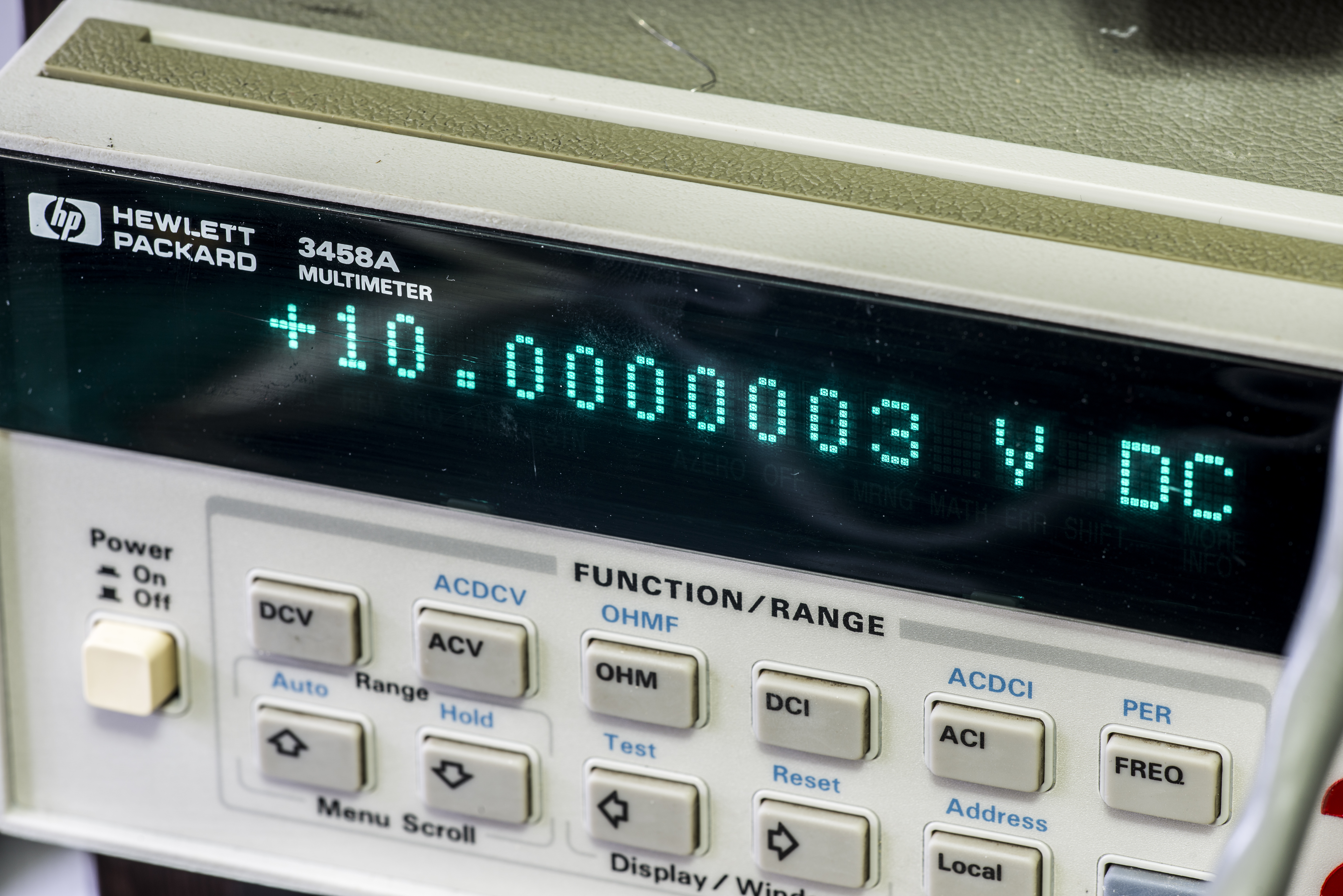
Image 25: xDevs.com FX
Test setup with four 8.5-digit DMMs and Keithley 7168 based scanner to check 3-week stability vs KX references:
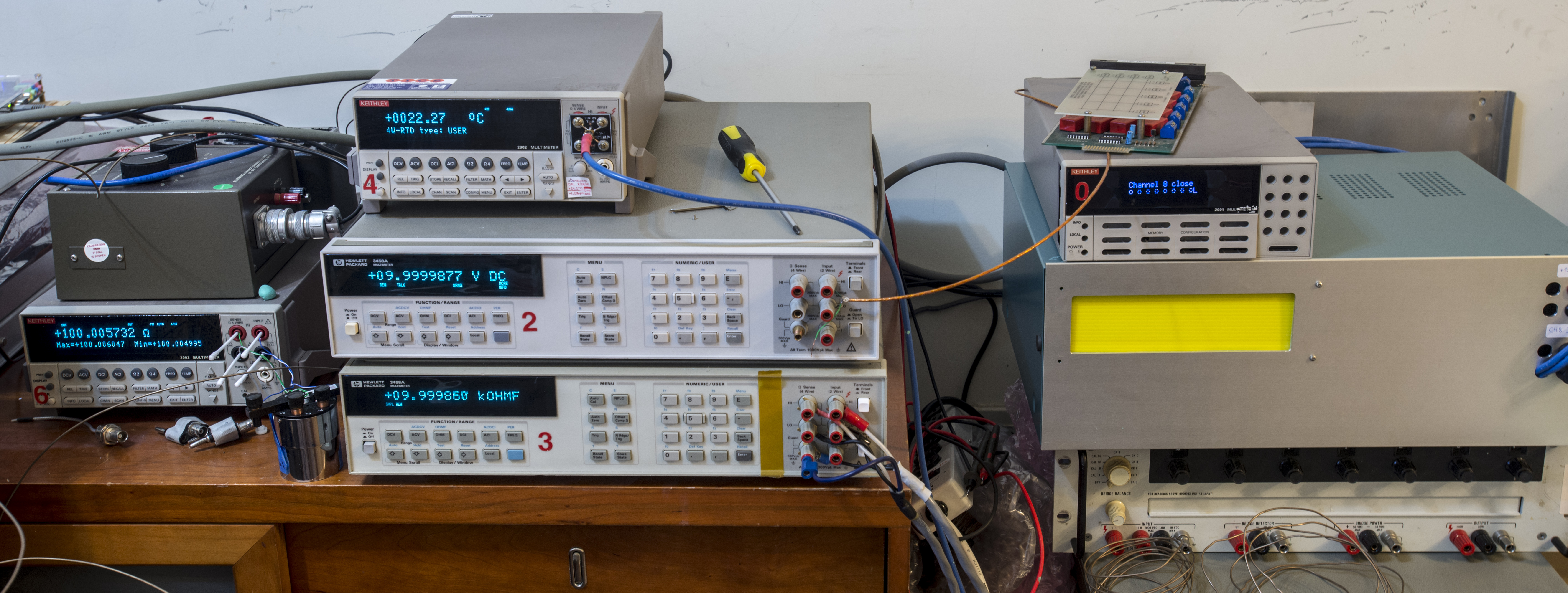
Image 26: xDevs.com FX
And more chips received for assembly of 10 units:

Image 27: xDevs.com FX
Other components photos.
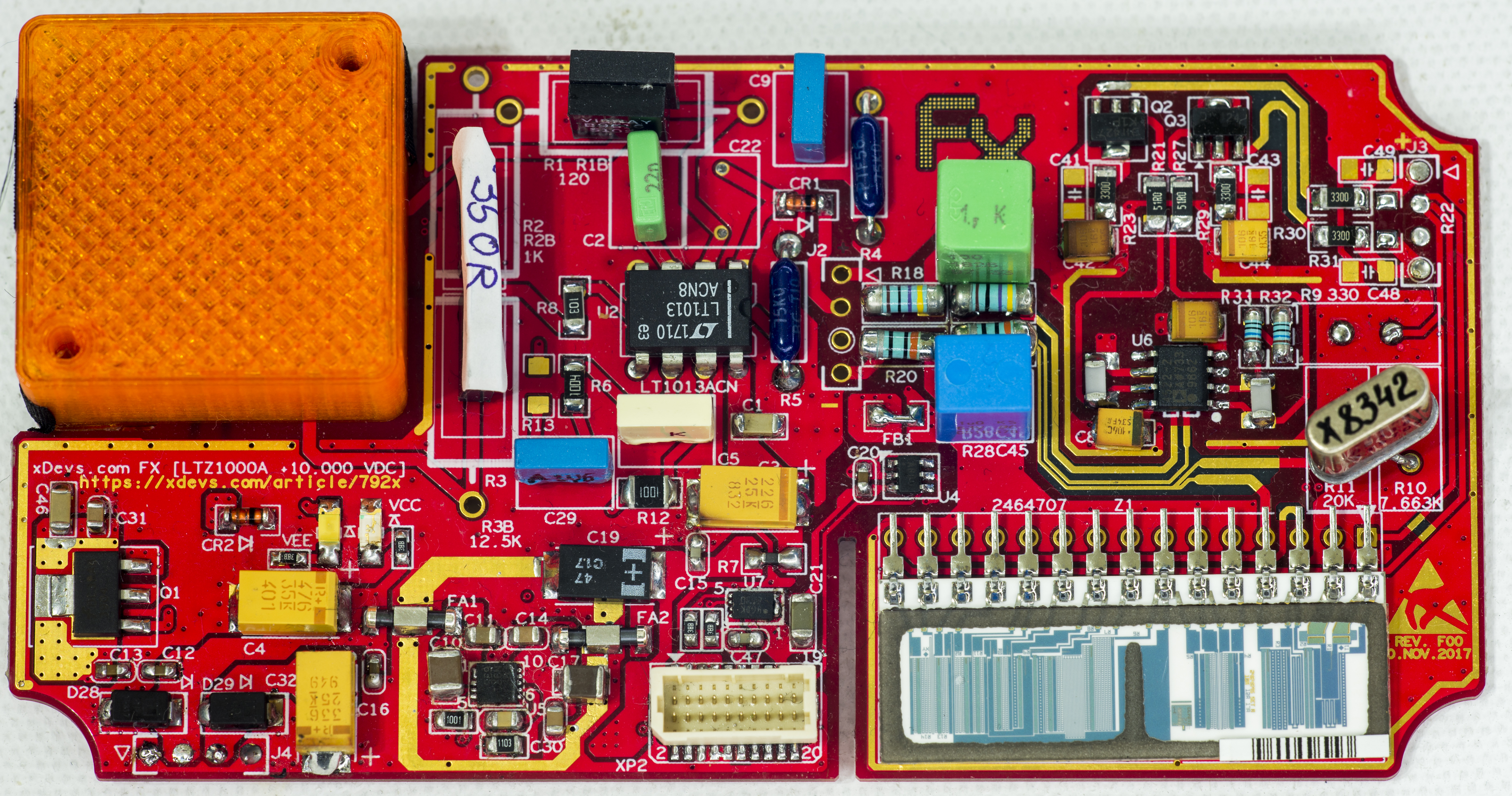
Image 28: xDevs.com FX
3D-printed plastic cap to shield LTZ1000ACH chip is required to obtain low noise performance out of the reference module.

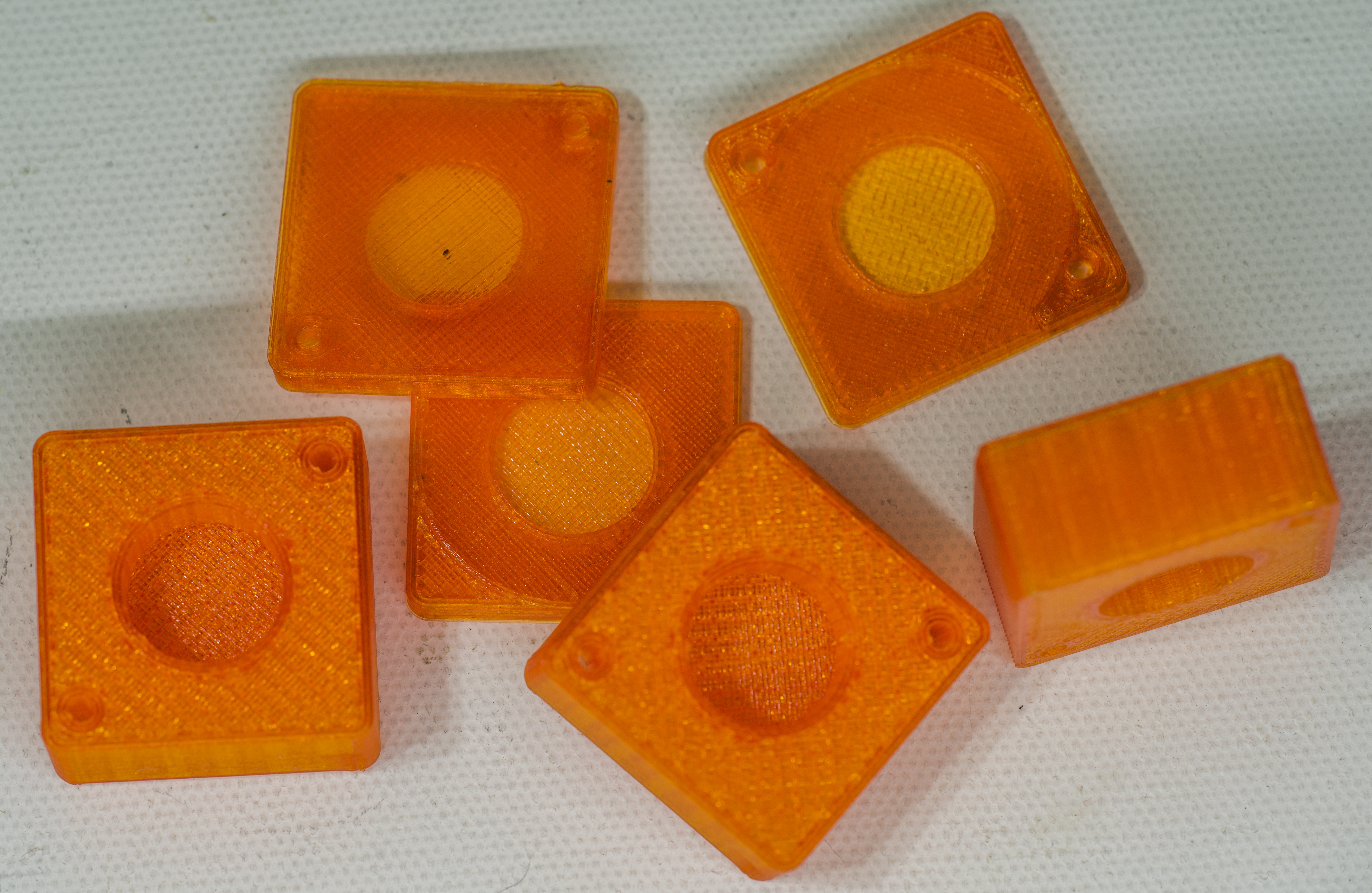
Image 29-30: xDevs.com FX
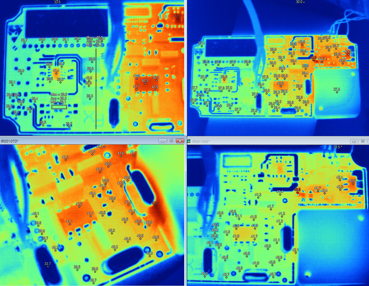
Thermal images
Running board was checked for thermal gradients, using Fluke Ti32 thermal camera:
Sorting LTZ1000ACH chips and Fluke networks
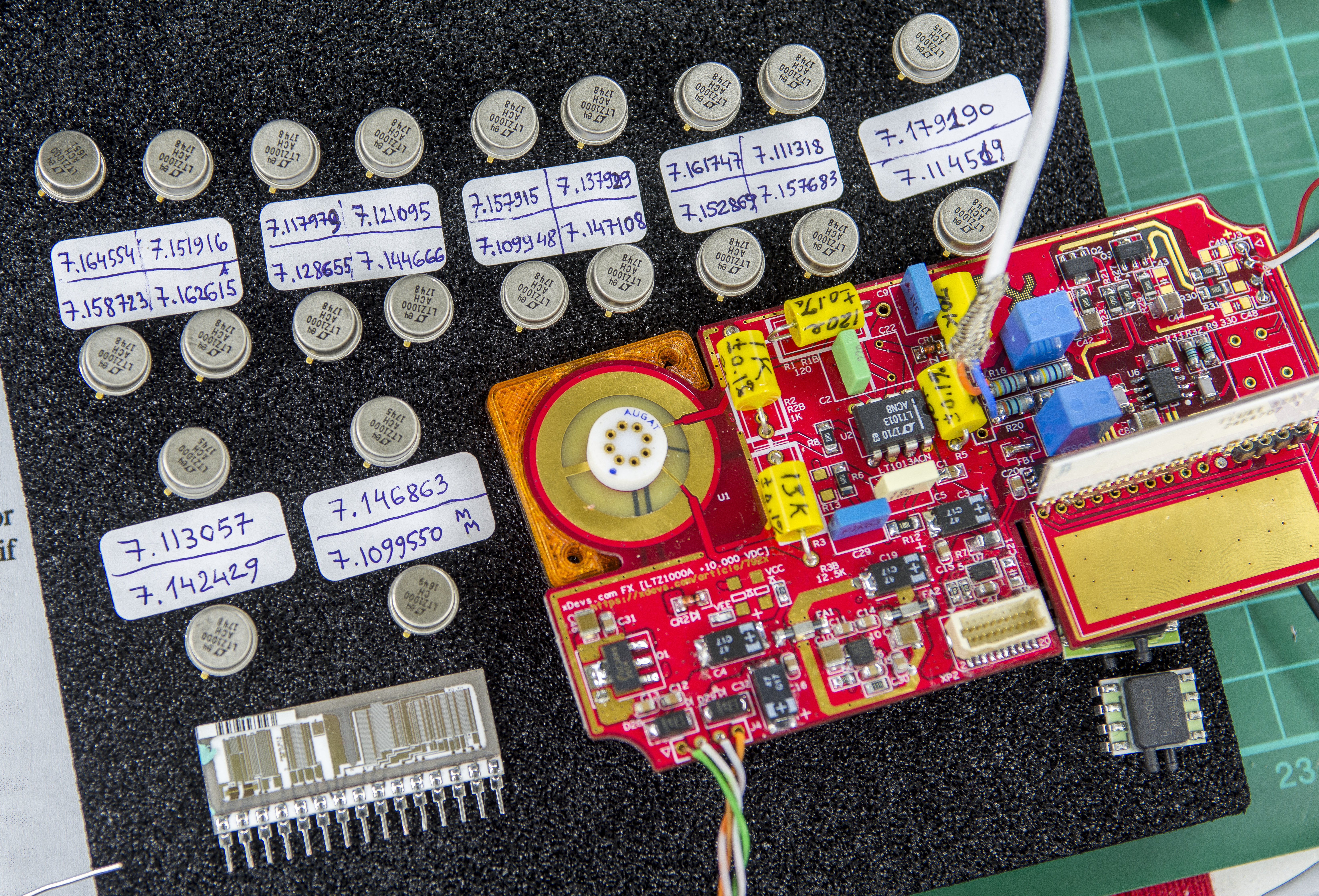
Image 31: xDevs.com FX

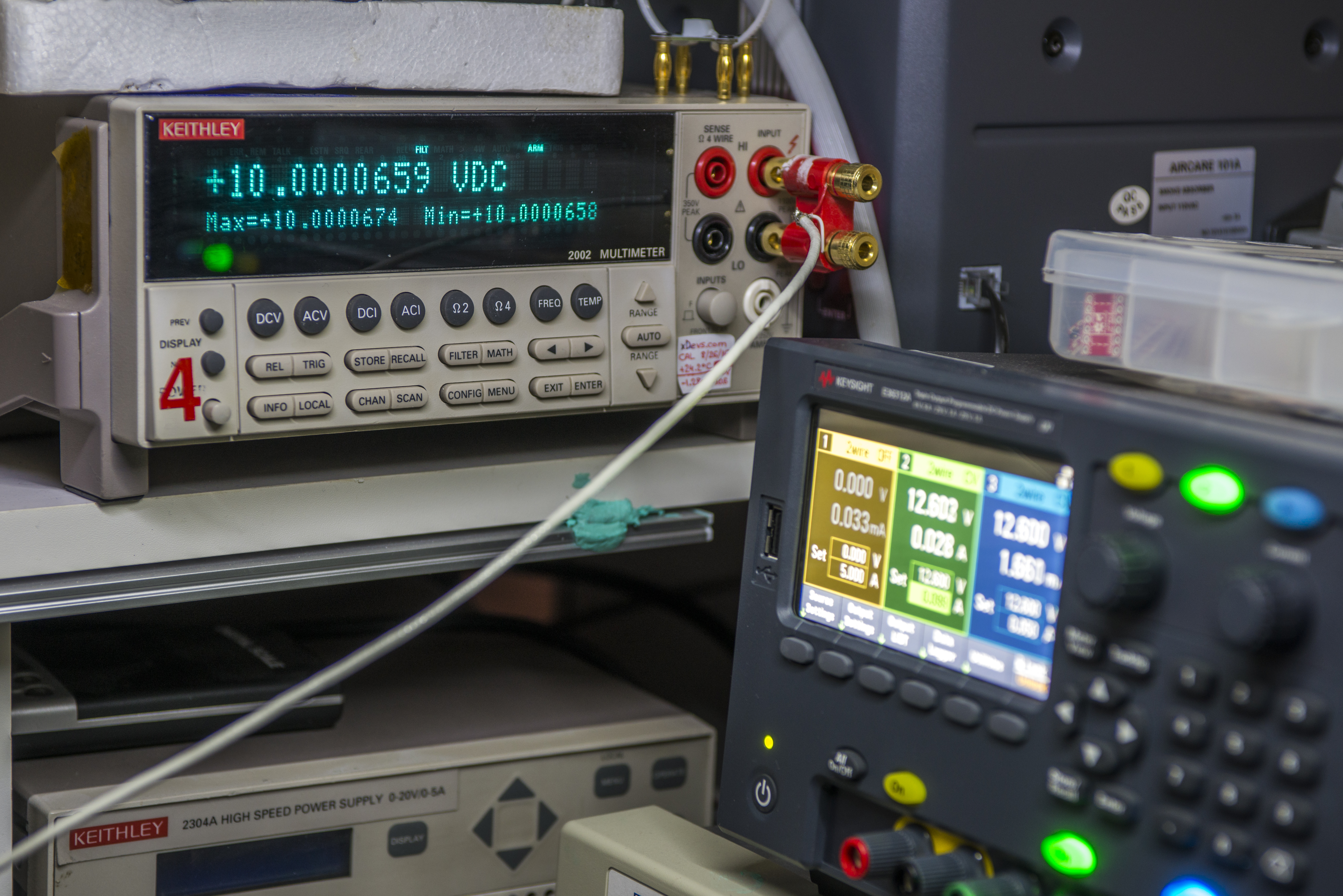
Image 32-33: xDevs.com FX
Time stability performance of prototype 4 by Allan Deviation math with AlaVar 5.2 software tool.
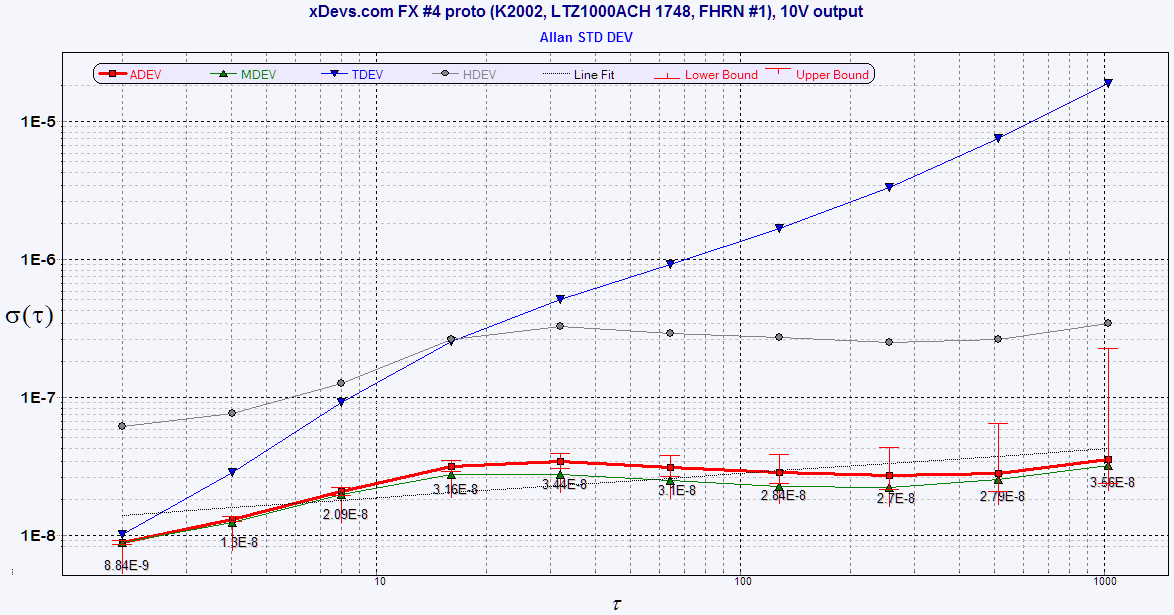
Image 34: xDevs.com FX
Regular data set graph, of same test run: https://xdevs.com/fx4_test1_2002-4/
Front panel and guard shield modify to add binding posts for 10V output
Bit of progress of target device, why FX reference actually created… Conversion of 792A Power Pack into 10VDC battery-powered reference. Fluke 792A Power pack front chassis and inner frame had to be modified to implement Low Thermal 5-way binding posts.


Image 51-52: xDevs.com FX
Main aluminum frame of 792A transfer box and power pack is actually exactly the same, only front face plate is different and guard inner shield does not have holes for shaft and terminals. Outer case made unified with 792A transfer unit, already having cutouts for posts. All we need to do is to add missing holes on the decorative aluminum front panel here.
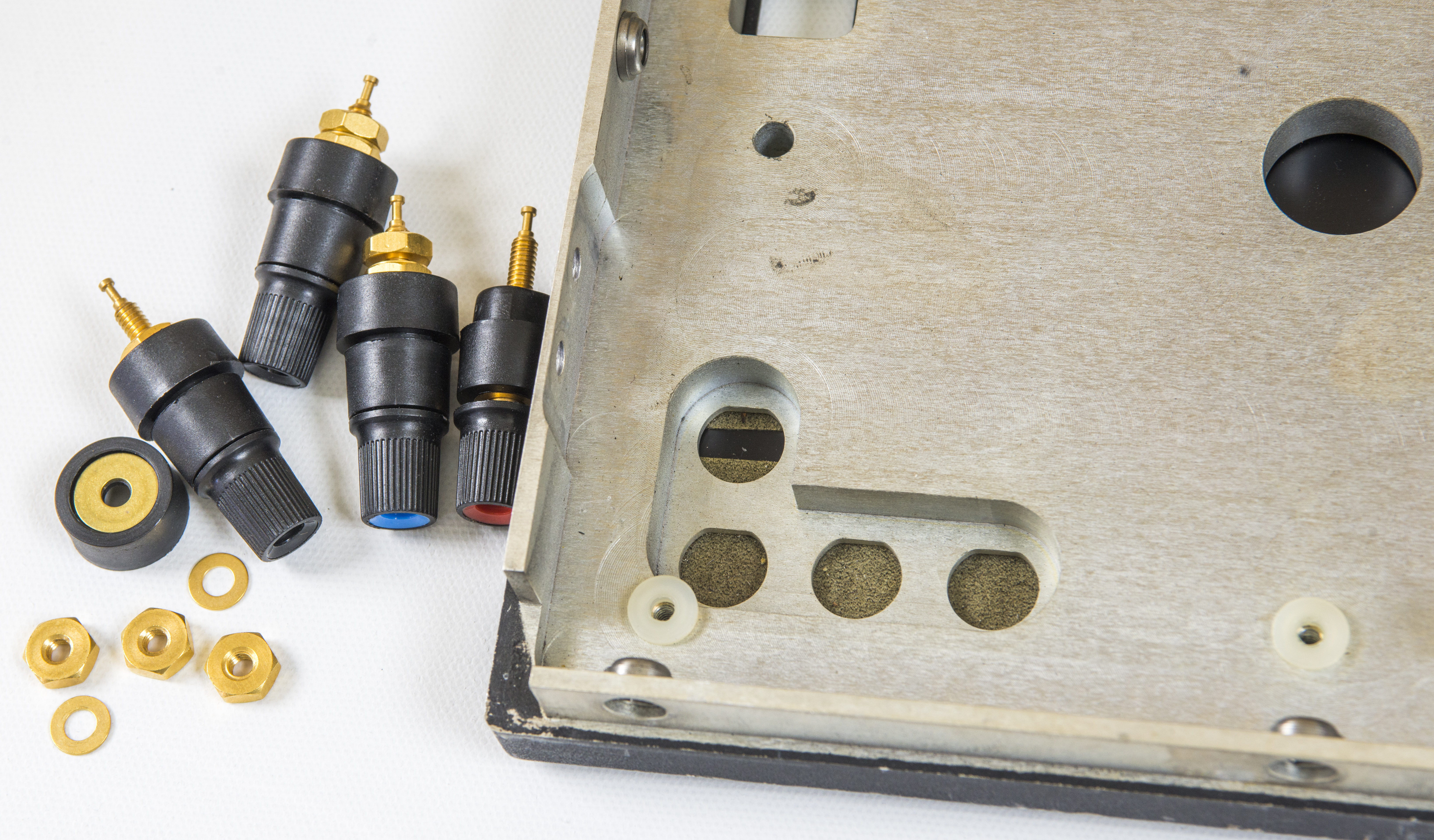

Image 35-36: xDevs.com FX
I need 4 posts, because FX output is 4-wire, force and sense wires are separate, so I can use it to drive resistive loads (to act as current source).
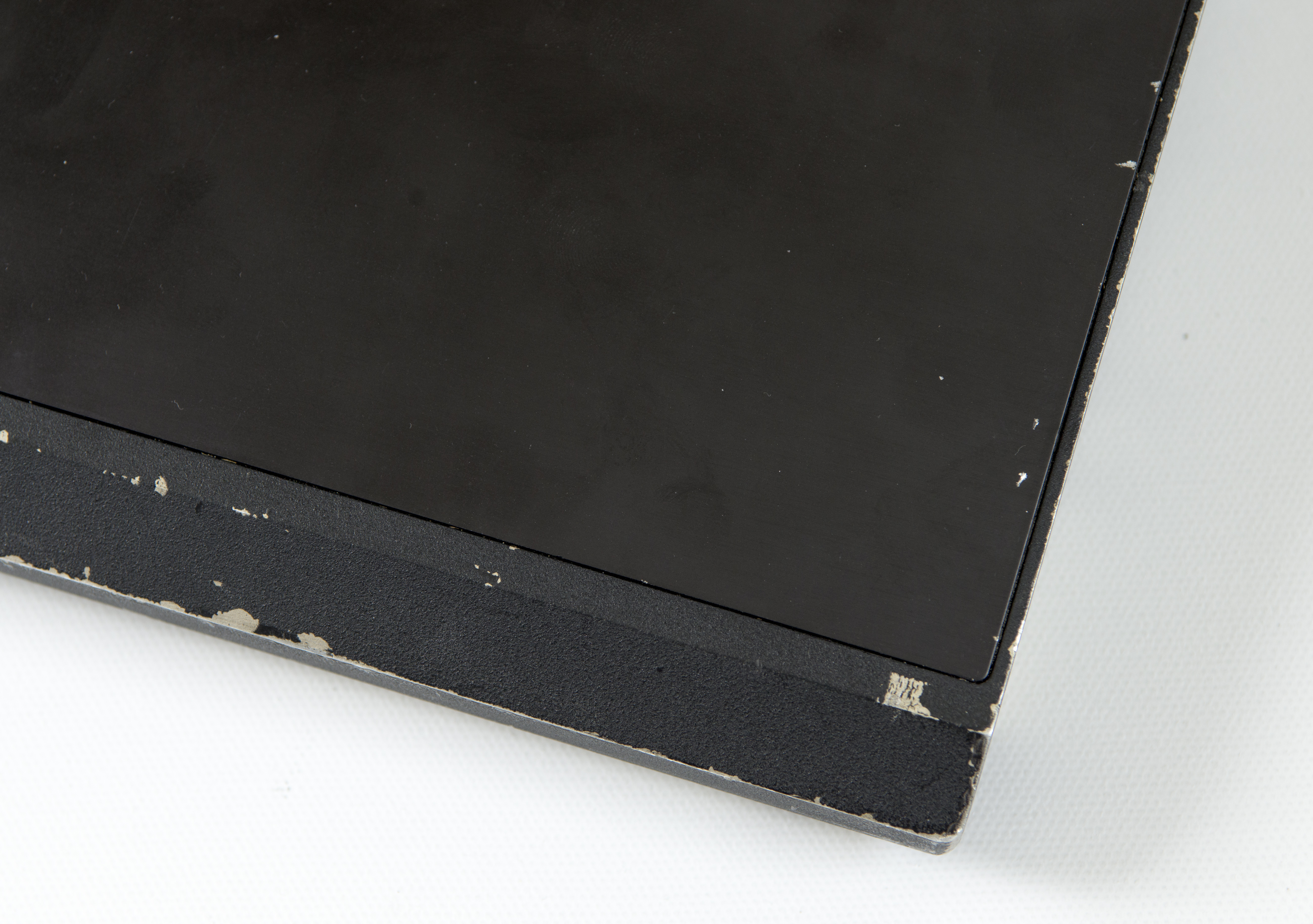
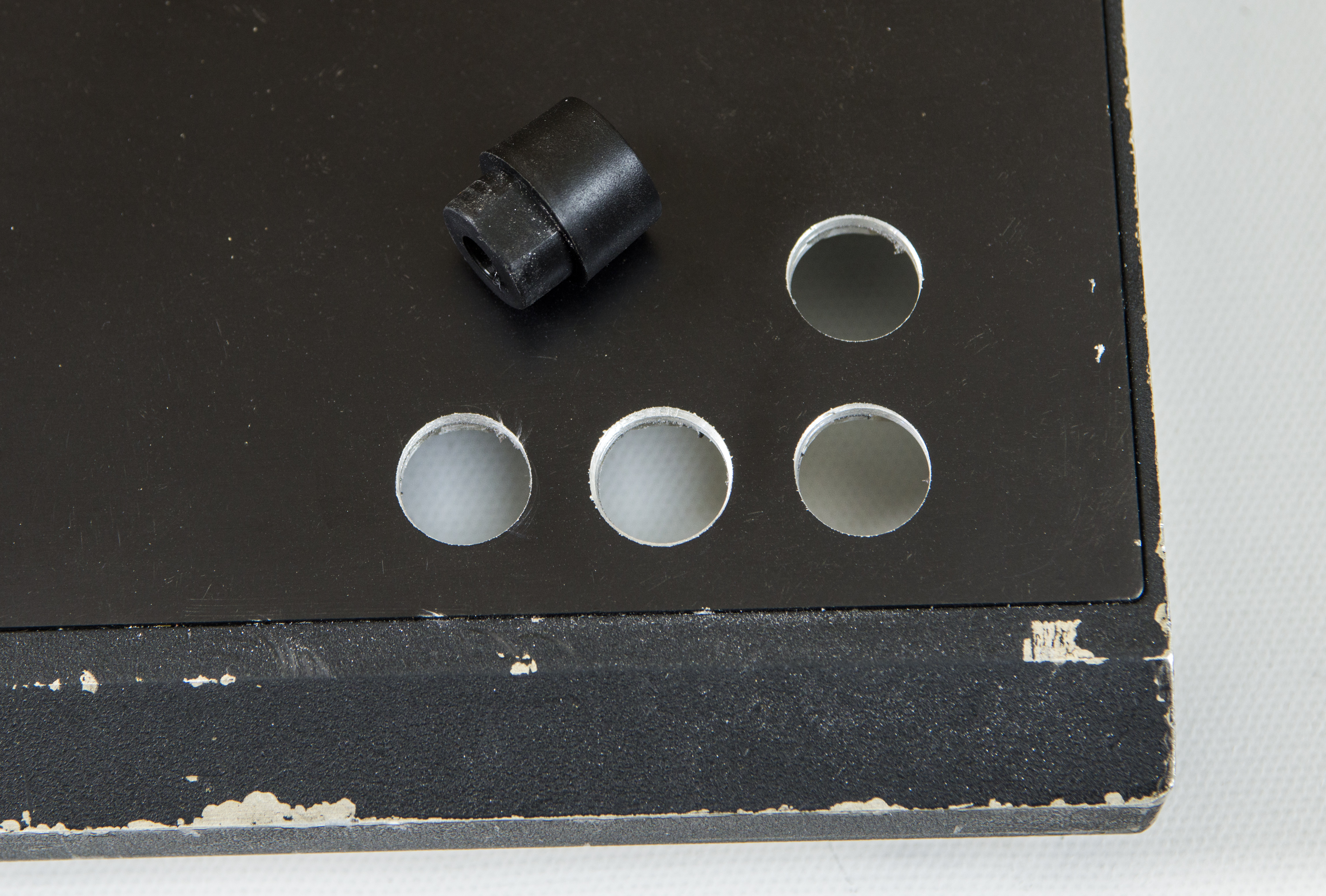
Image 53-54: xDevs.com FX
Like a bought one? Almost.
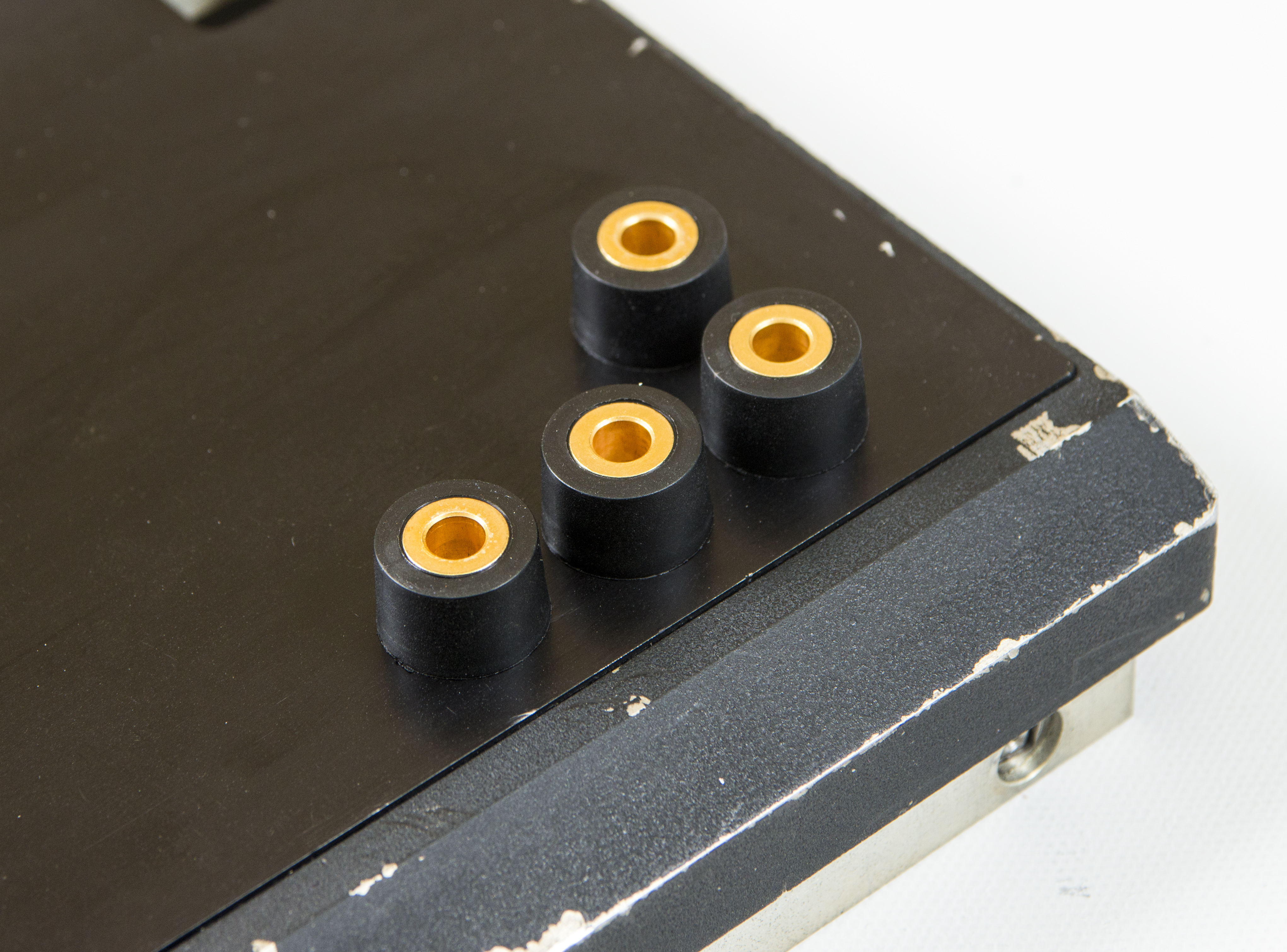

Image 55-56: xDevs.com FX
Cable lugs are tight in space, and posts ends had to be trimmed a bit to make it fit with the inner shield frame.
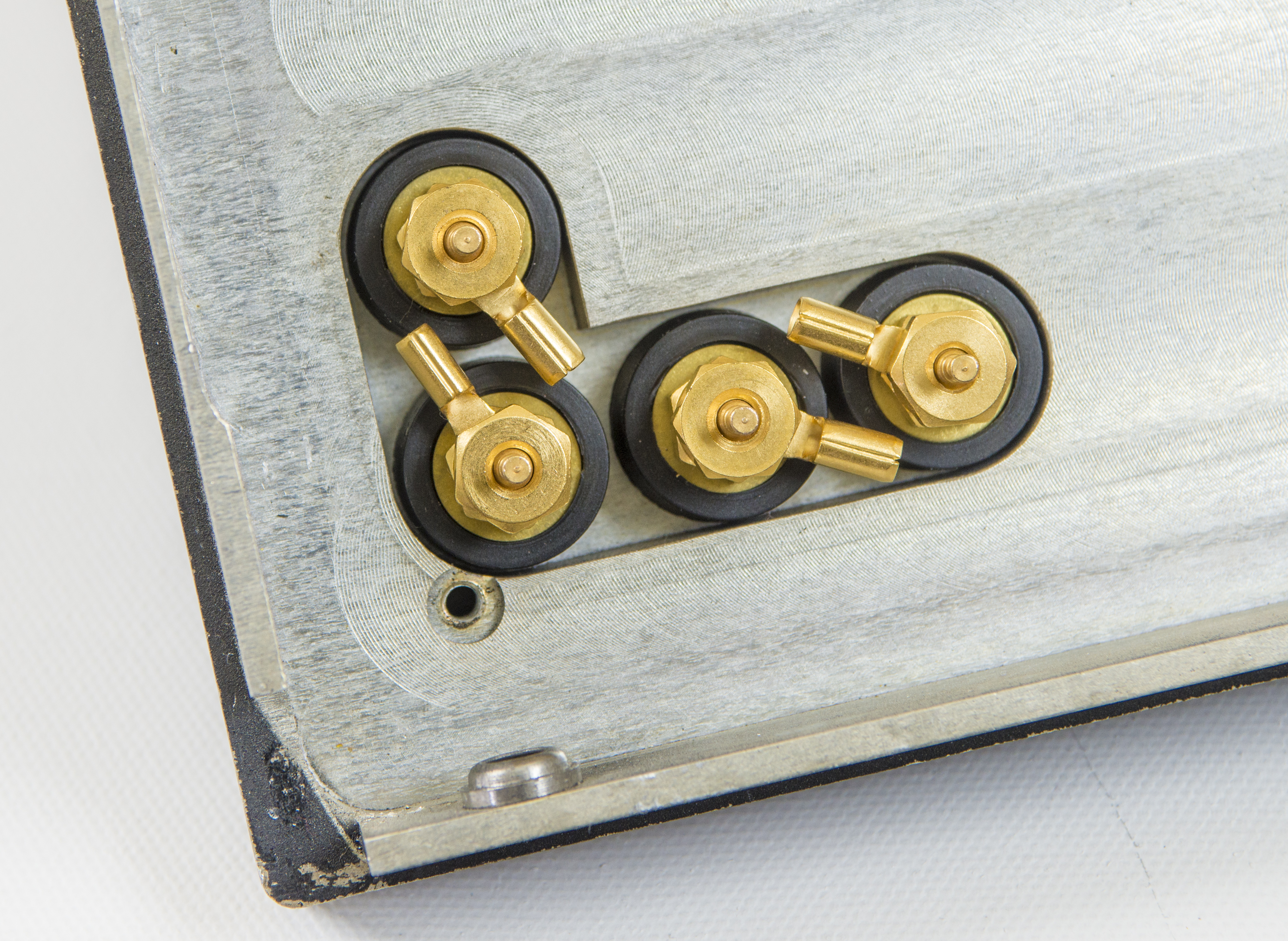

Image 57-58: xDevs.com FX
We opted for different colors for sense and force terminals, both positive and negative sides, providing true 4-wire output for improved versatility. Reference could be used as precision voltage source or as current source in the result.
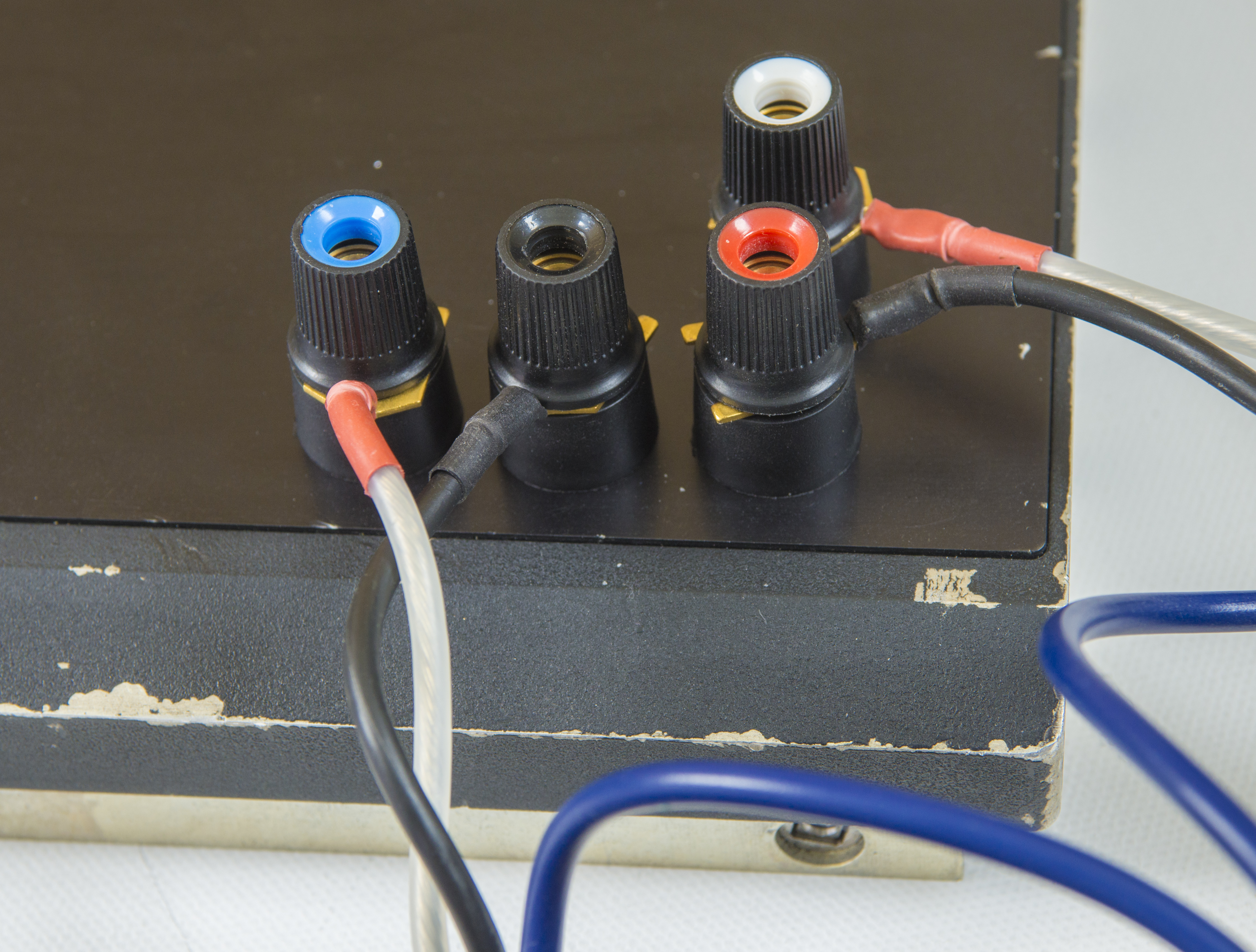
Image 59: xDevs.com FX
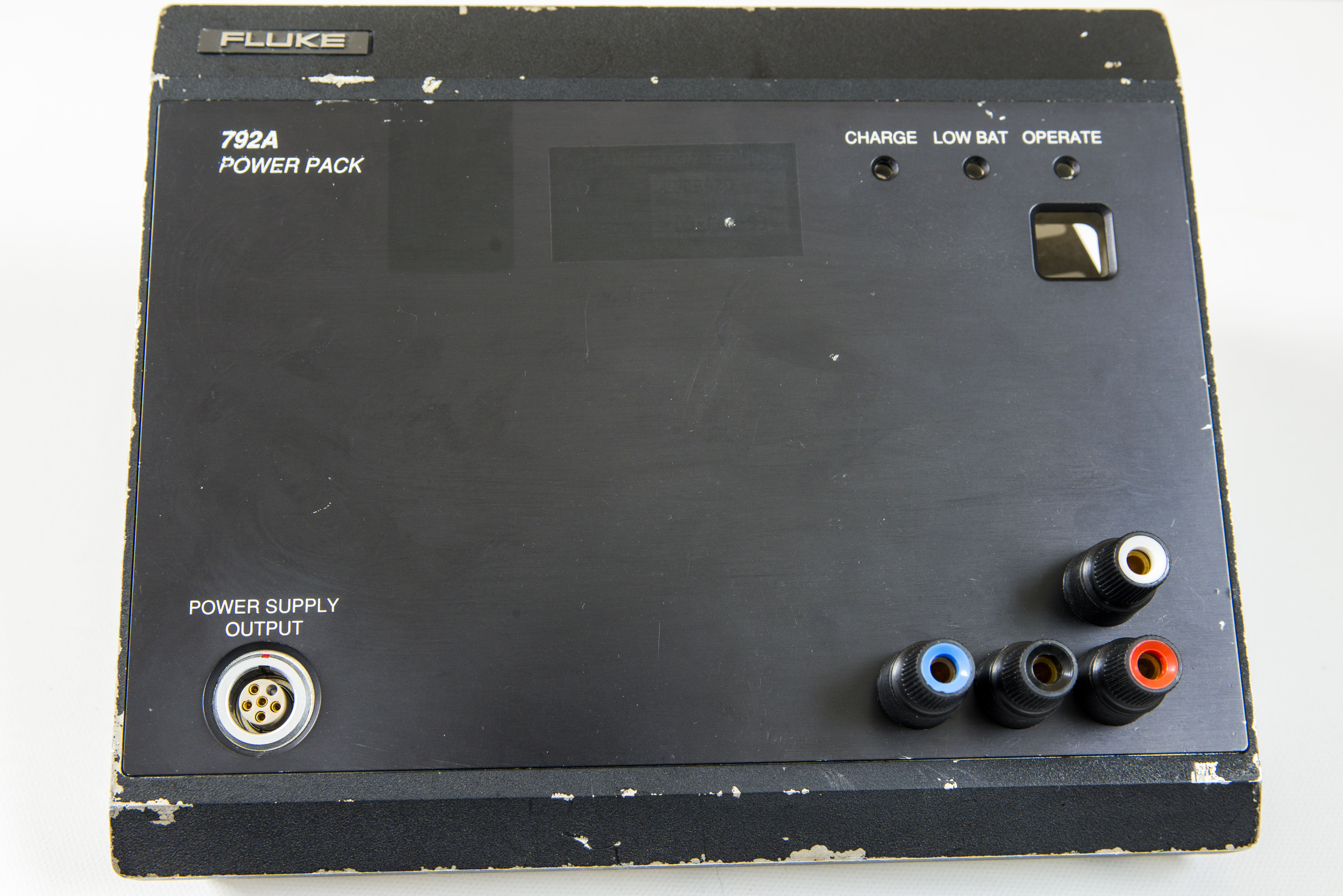
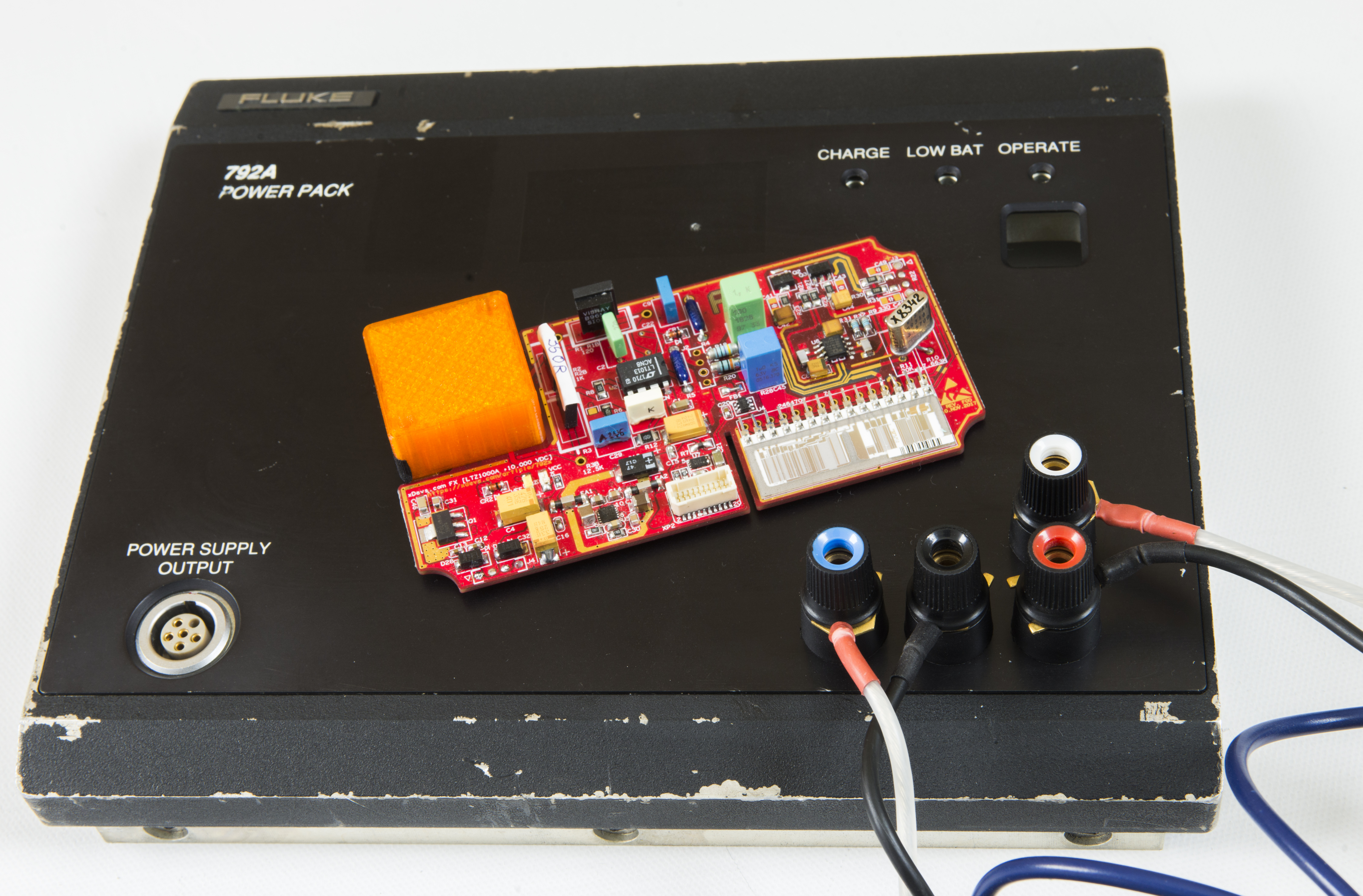
Image 60-61: xDevs.com FX
LEMO power supply output port still works as original design, providing regulated isolated +11/-11, in case I need connection to real 792A transfer unit.
Alternative was not to drill anything, but to replace the LEMO EGG connector from 5 pin one to 12 pin version, but I opted against this way due to concerns with thermal EMF performance of LEMO connector. I got 8-pin version of mechanically compatible connector system to do some experiments in other projects:

Image 41: xDevs.com FX
Digital ID function
EEPROM IC is used onboard to store calibration data, history logs of the module and it’s configuration. EEPROM is accessible by I2C interface by address 50h and 58h for used M24128-DFMC6TG device.
root@vfd /home/pi # i2cdetect -y 1
     0  1  2  3  4  5  6  7  8  9  a  b  c  d  e  f
00:          -- -- -- -- -- -- -- -- -- -- -- -- --
10: -- -- -- -- -- -- -- -- -- -- -- -- -- -- -- --
20: -- -- -- -- -- -- -- -- -- -- -- -- -- -- -- --
30: -- -- -- -- -- -- -- -- -- -- -- -- -- -- -- --
40: -- -- -- -- -- -- -- -- -- -- -- -- -- -- -- --
50: 50 -- -- -- -- -- -- -- 58 -- -- -- -- -- -- --
60: -- -- -- -- -- -- -- -- -- -- -- -- -- -- -- --
70: -- -- -- -- -- -- -- --
Dump blank chip for testing:
root@vfd /home/pi # i2cdump -y 1 0x50
No size specified (using byte-data access)
     0  1  2  3  4  5  6  7  8  9  a  b  c  d  e  f    0123456789abcdef
00: ff ff ff ff ff ff ff ff ff ff ff ff ff ff ff ff    ................
10: ff ff ff ff ff ff ff ff ff ff ff ff ff ff ff ff    ................
20: ff ff ff ff ff ff ff ff ff ff ff ff ff ff ff ff    ................
30: ff ff ff ff ff ff ff ff ff ff ff ff ff ff ff ff    ................
40: ff ff ff ff ff ff ff ff ff ff ff ff ff ff ff ff    ................
50: ff ff ff ff ff ff ff ff ff ff ff ff ff ff ff ff    ................
60: ff ff ff ff ff ff ff ff ff ff ff ff ff ff ff ff    ................
70: ff ff ff ff ff ff ff ff ff ff ff ff ff ff ff ff    ................
80: ff ff ff ff ff ff ff ff ff ff ff ff ff ff ff ff    ................
90: ff ff ff ff ff ff ff ff ff ff ff ff ff ff ff ff    ................
a0: ff ff ff ff ff ff ff ff ff ff ff ff ff ff ff ff    ................
b0: ff ff ff ff ff ff ff ff ff ff ff ff ff ff ff ff    ................
c0: ff ff ff ff ff ff ff ff ff ff ff ff ff ff ff ff    ................
d0: ff ff ff ff ff ff ff ff ff ff ff ff ff ff ff ff    ................
e0: ff ff ff ff ff ff ff ff ff ff ff ff ff ff ff ff    ................
f0: ff ff ff ff ff ff ff ff ff ff ff ff ff ff ff ff    ................
Testing.
Unit with reference is powered continuosuly since end of January 2018.
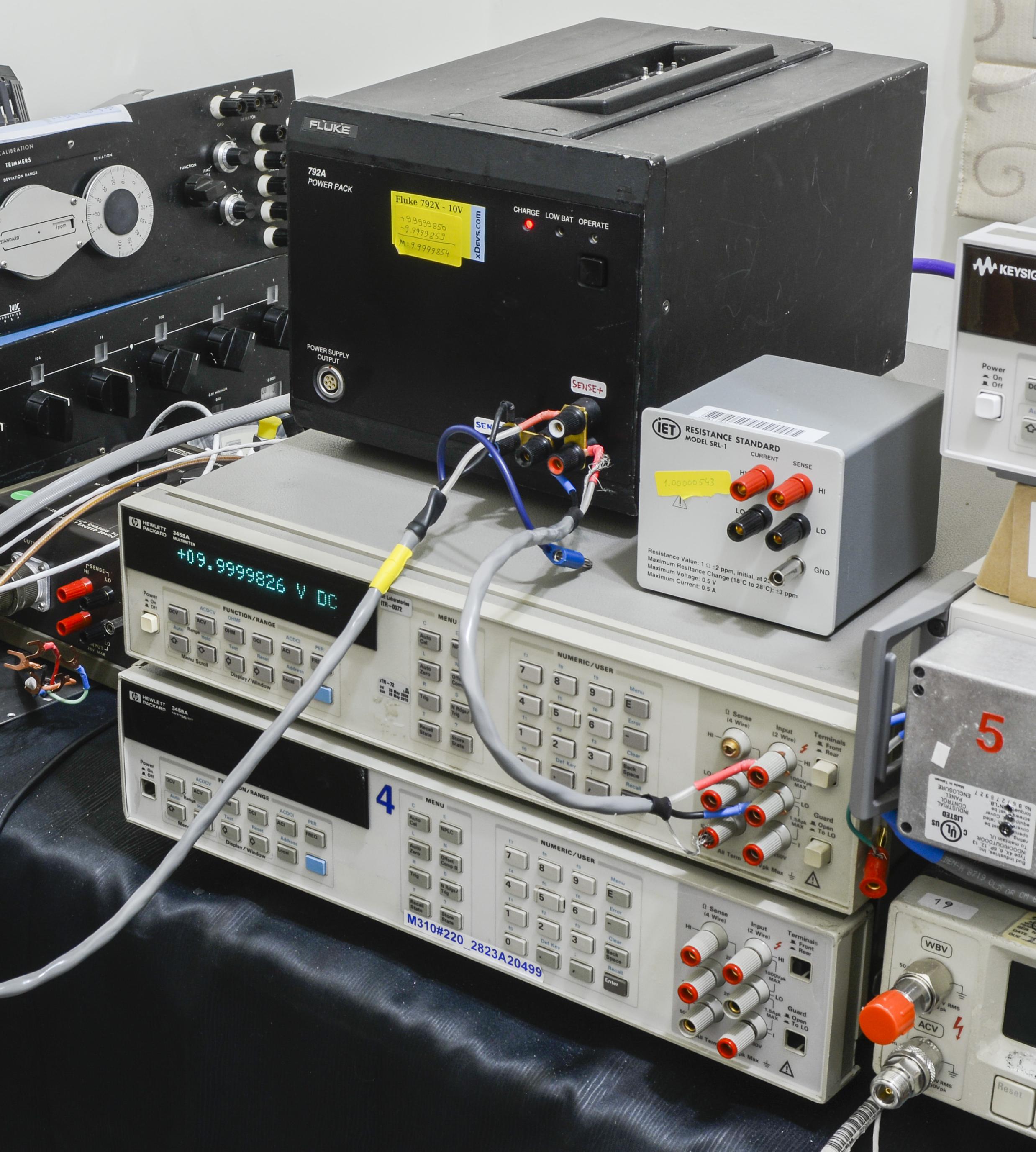
Image 62: xDevs.com FX
Calibration measurements setup:
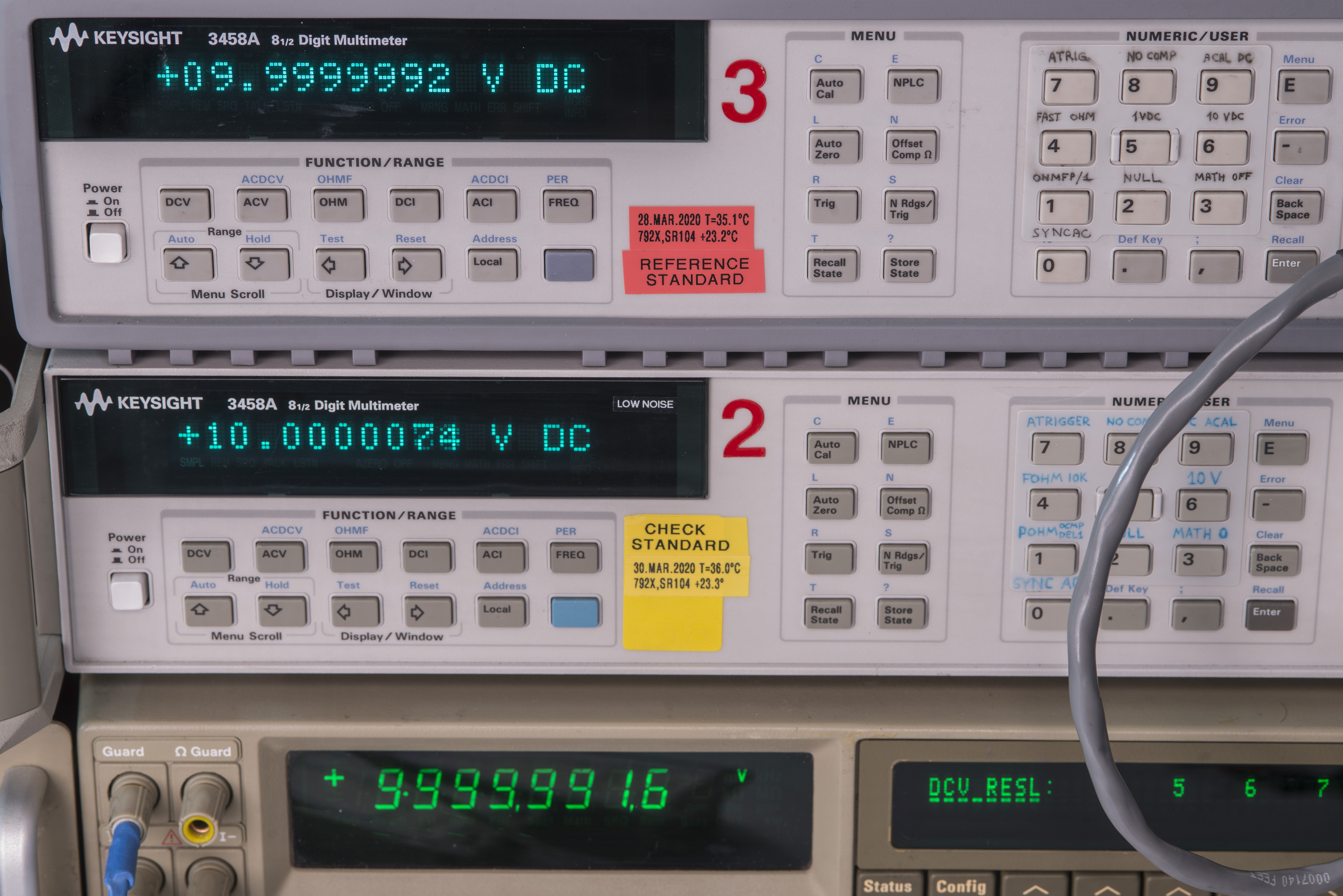
Image 62: xDevs.com FX calibrated using maintained tandem of 3458As
Build 10 units for EEVBlog community

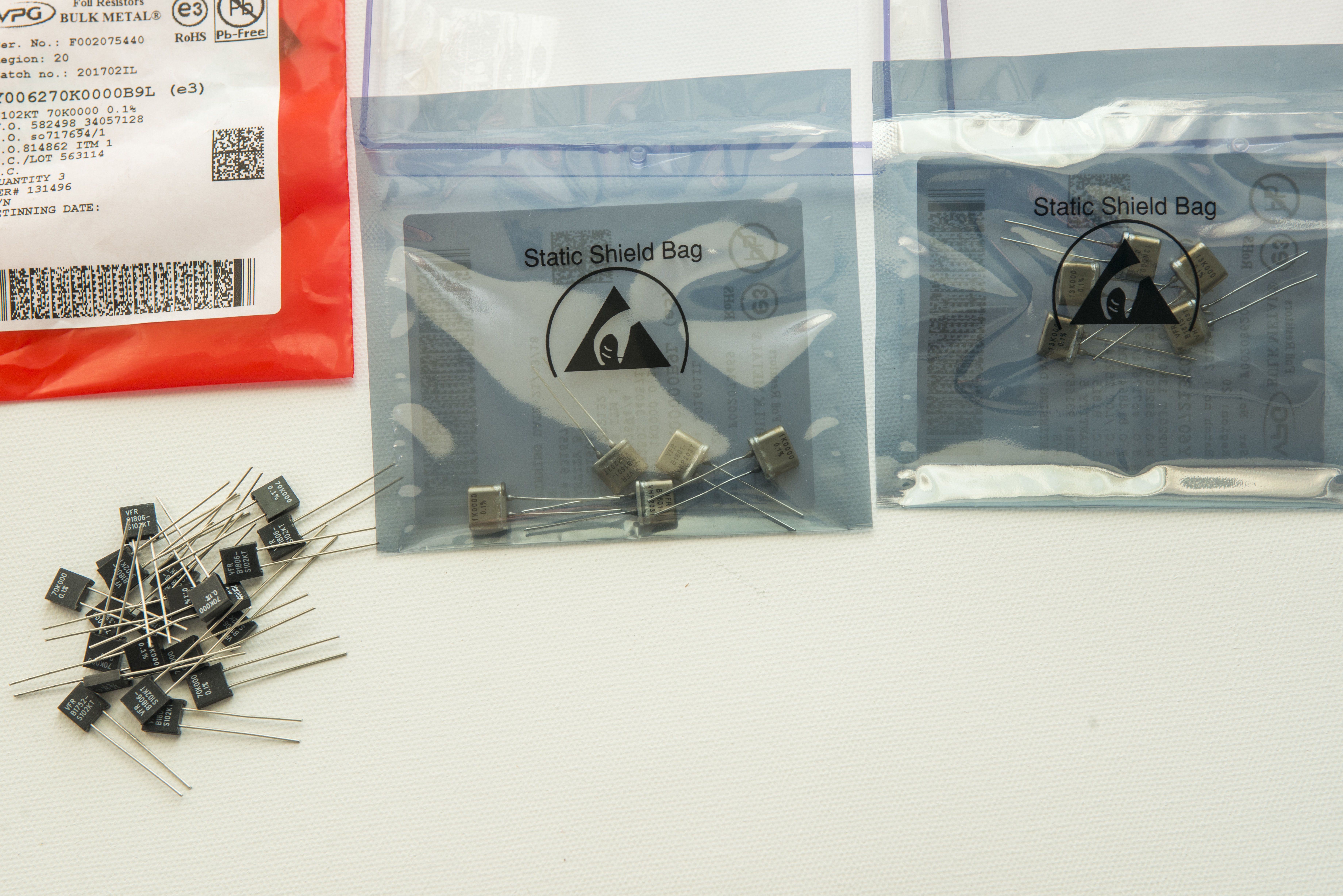
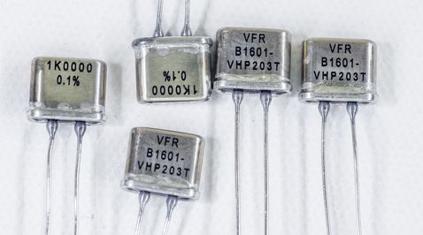
Image 42-44: xDevs.com FX

Image 45: xDevs.com FX
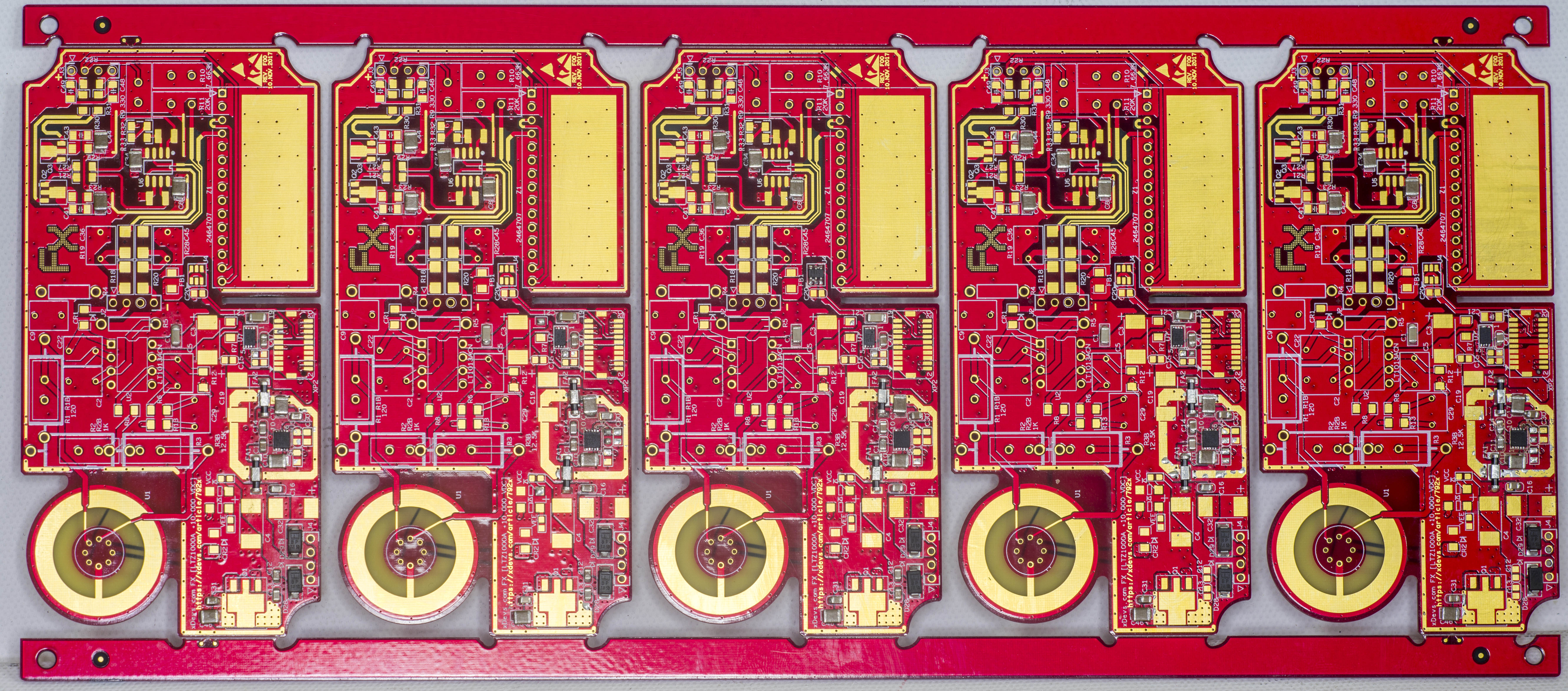
Image 46: xDevs.com FX

Image 47: xDevs.com FX
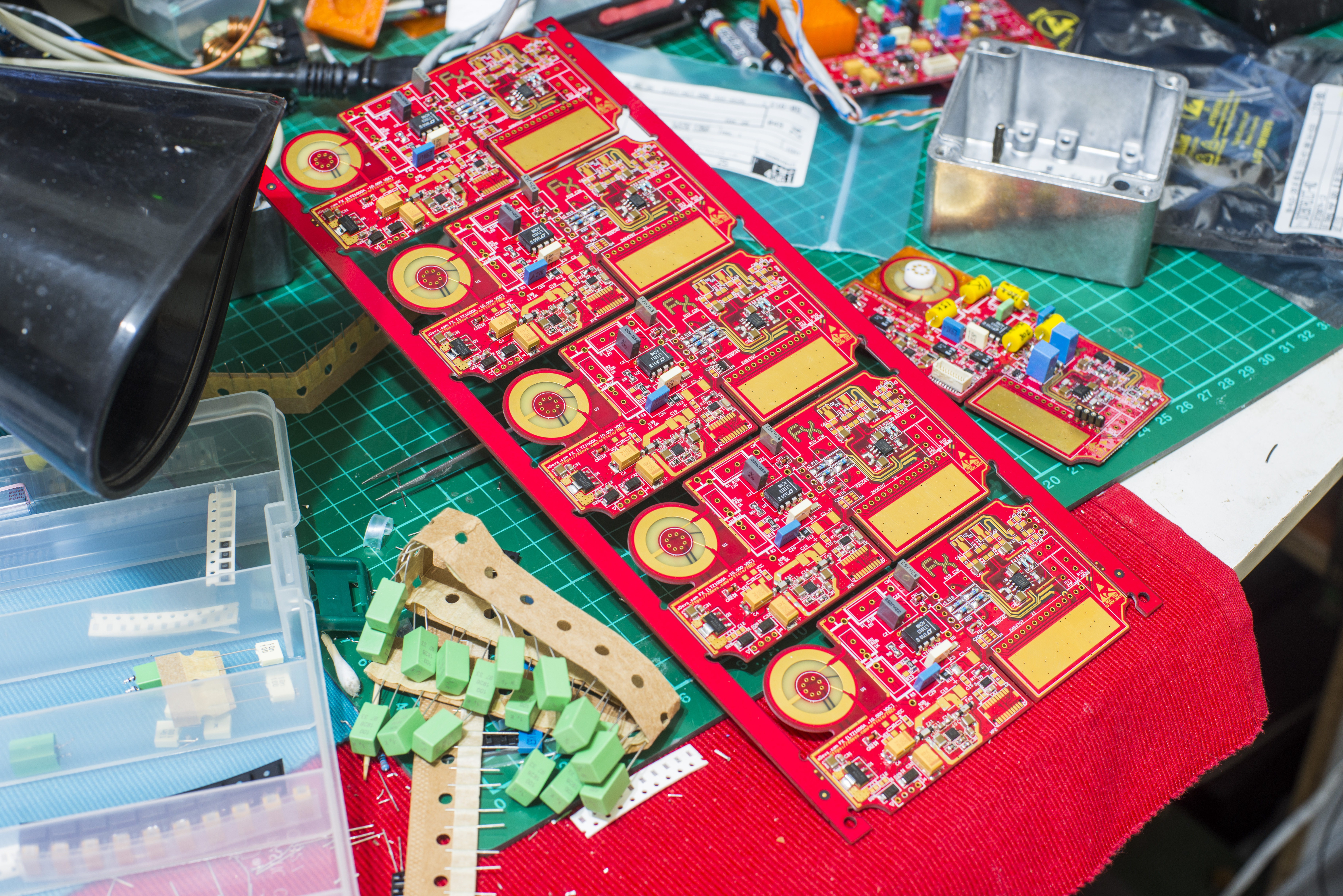
Image 48: xDevs.com FX

Image 49: xDevs.com FX
Before assembly resistors were tested for temperature stability and matching groups were selected.
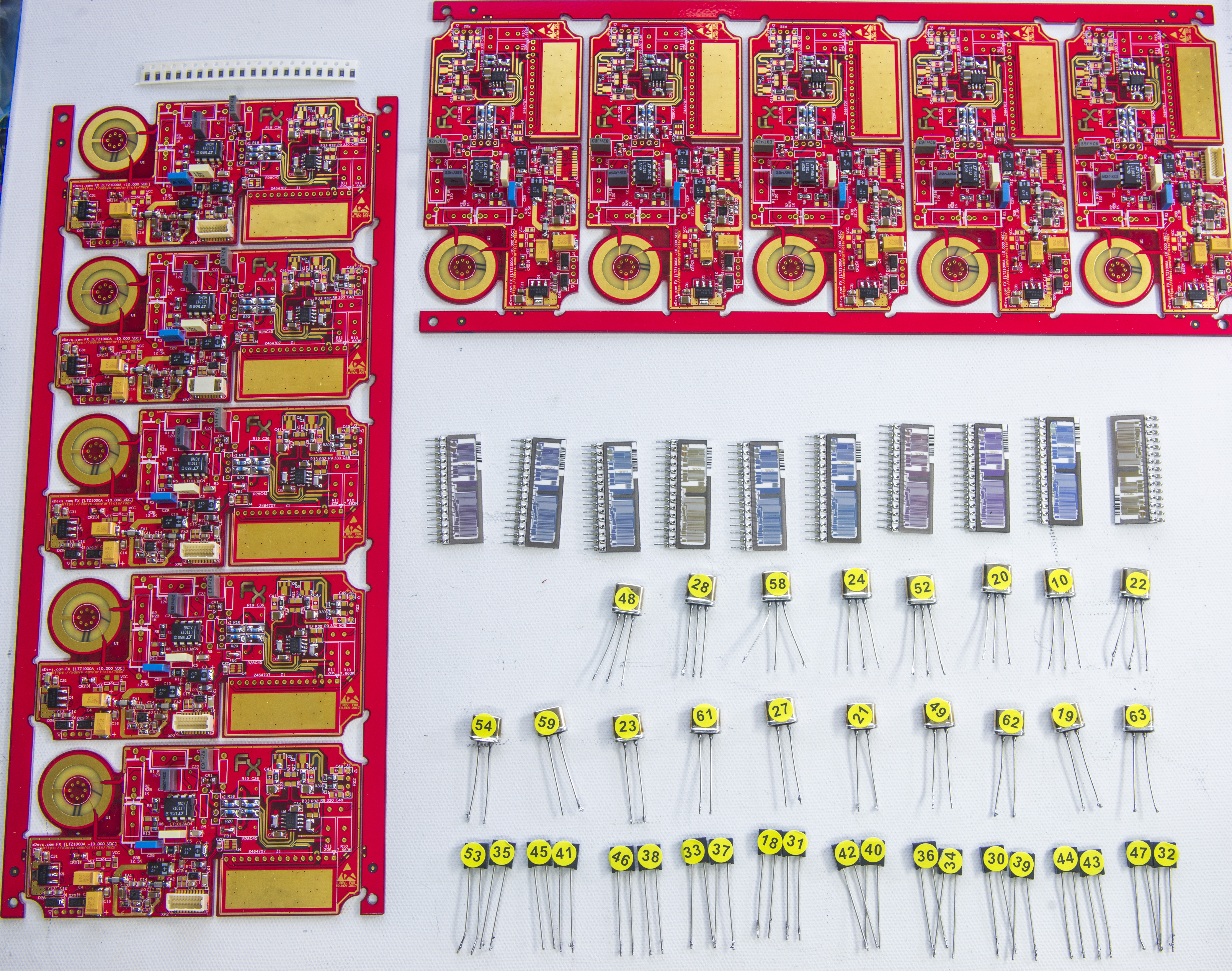
Image 50: xDevs.com FX
Resistor test data is covered in dedicated article.
xDevs.com FX owners and module logs
Summary available in table.
| Member | Board/module photo | Voltage | TC | Calibrated | Delivered |
|---|---|---|---|---|---|
| Echo | 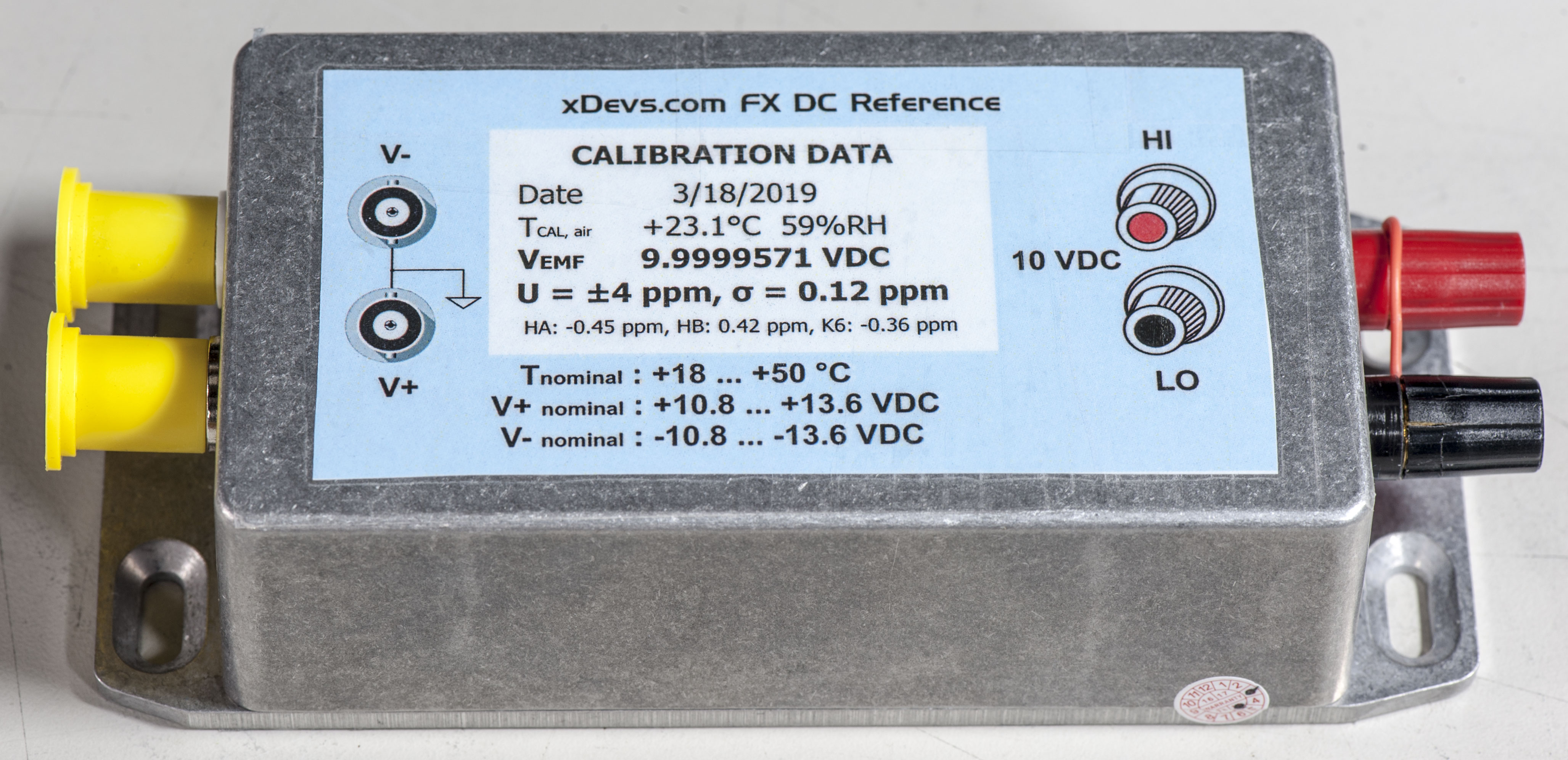 |
+9.9999571 VDC | +0.01 ppm/K | 3/19/2019 | Yes |
| EEVBlog US calibration comparison team | |
+9.9999590 VDC | -0.025 ppm/K | 5/17/2019 | Yes |
| montemcguire | 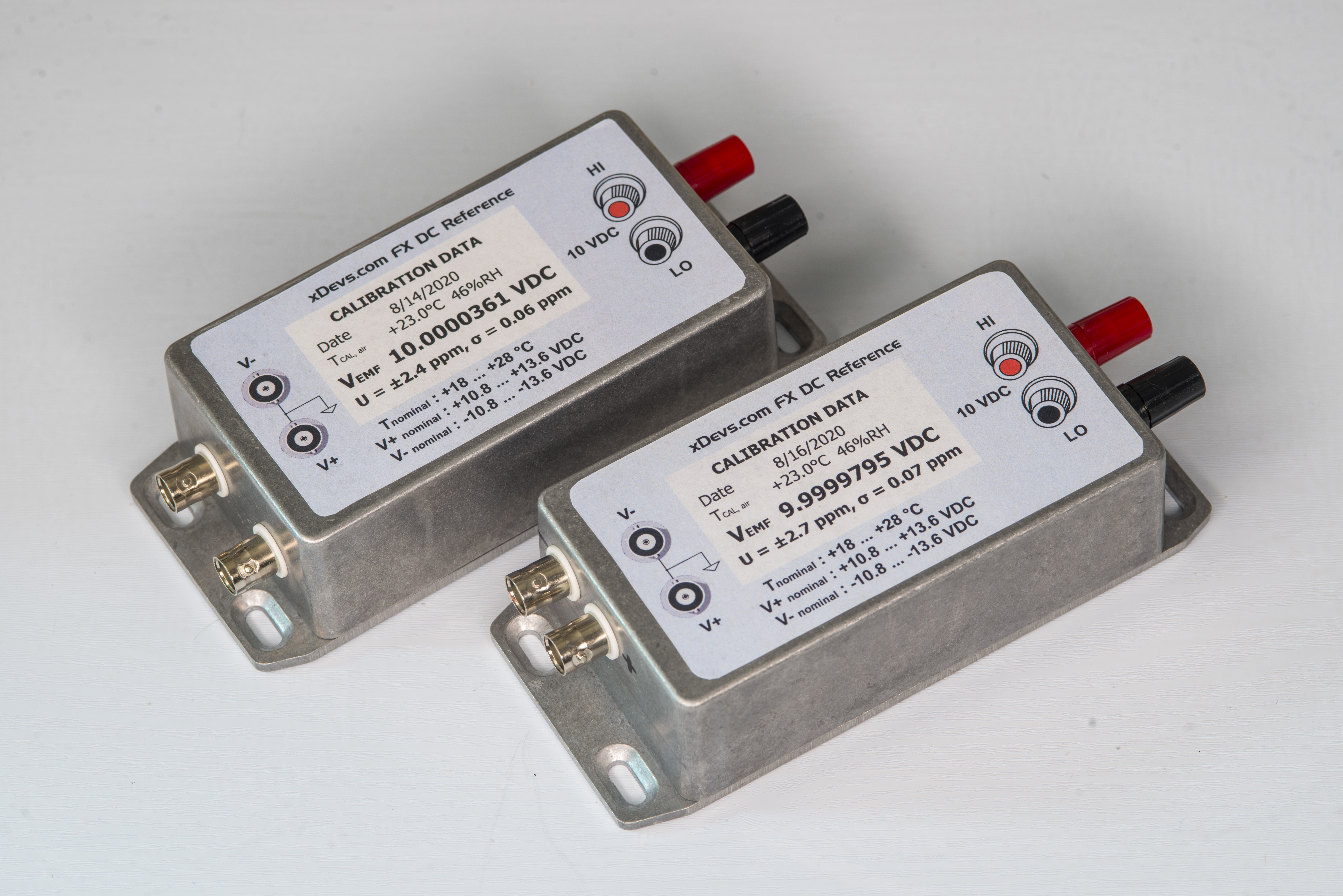 |
+9.9999795 VDC | -0.06 ppm/K | 8/16/2020 | Yes |
| MM | +9.9999695 VDC | -0.0163 ppm/K | 9/20/2019 | Yes | |
| bck1 | +9.9999826 VDC | -0.0372 ppm/K | 10/10/2019 | Yes | |
| bck2 | +9.9999655 VDC | -0.0475 ppm/K | 10/10/2019 | Yes | |
| dr.diesel | +9.9999xxx VDC | “x.xx ppm/K” | No | ||
| chriswebb | +9.9999xxx VDC | “x.xx ppm/K” | No | ||
| PeLuLe unit A | +9.9999xxx VDC | “x.xx ppm/K” | No | ||
| PeLuLe unit B | +9.9999xxx VDC | “x.xx ppm/K” | No | ||
| CM | +9.9999xxx VDC | “x.xx ppm/K” | No | ||
| zucca | +9.9999xxx VDC | “x.xx ppm/K” | No |
Details about each particular device are covered in sections.
Echo FX reference
| Echo FX module | Parameter | Unit | Notes |
|---|---|---|---|
| Calibration date | 19.MAR.2019 | +23 °C ambient, by 3458AB | |
| Reference Temp T | 23.00 | °C | |
| Nominal output | 10.000000 | VDC | |
| 1st fit const | -8.911939E-08 | ||
| 2nd fit const | 2.765246E-09 | ||
| Gain const | 9.9999575 | VDC | |
| EMF, T23 | 9.9999569 | VDC | |
| α T23 | +0.0038 | ppm/K | |
| β | +0.0003 | ppm/K2 | |
| ΔT23 | -4.31 | ppm | Offset from nominal |
| Temp at α=0 | 16.114 | °C | |
| EMF at α=0 | 9.9999568 | VDC | |
| TC, BOX, T20-50 | -0.0200 | ppm/K | |
| σT35 | 0.352 | µV | |
| Vnoise T35 | 2.75 | µVpk-pk | 0.1 – 10 Hz band |
| U, k=2 | 4.1 | µV/V | Within 24 hours, prior to shipping |
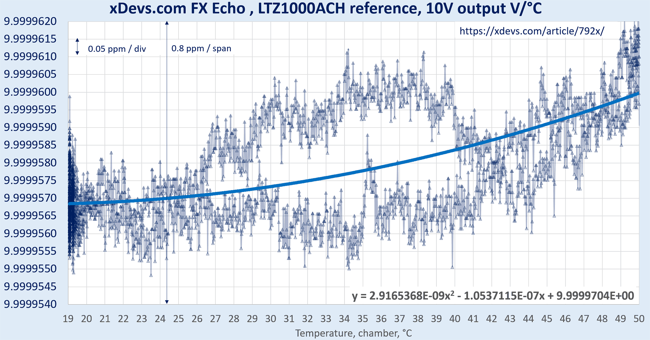
Image 63: xDevs.com FX
US EEVBlog Club reference
| US FX module | Parameter | Unit | Notes |
|---|---|---|---|
| Calibration date | 17.MAY.2019 | +23 °C ambient, by 3458AB | |
| Reference Temp T | 23.00 | °C | |
| Nominal output | 10.000000 | VDC | |
| 1st fit const | -9.48417E-07 | ||
| 2nd fit const | 1.52101E-08 | ||
| Gain const | 9.9999728 | VDC | |
| EMF, T23 | 9.9999590 | VDC | |
| α T23 | -0.0249 | ppm/K | |
| β | +0.0015 | ppm/K2 | |
| ΔT23 | -4.10 | ppm | Offset from nominal |
| Temp at α=0 | 31.177 | °C | |
| EMF at α=0 | 9.9999580 | VDC | |
| TC, BOX, T20-50 | -0.0298 | ppm/K | |
| σT35 | 0.352 | µV | |
| Vnoise T35 | 1.54 | µVpk-pk | 0.1 – 10 Hz band |
| U, k=2 | 4.06 | µV/V | Within 24 hours, prior to shipping |
US team module photos prior to final tests and assembly:

Image 64: xDevs.com FX
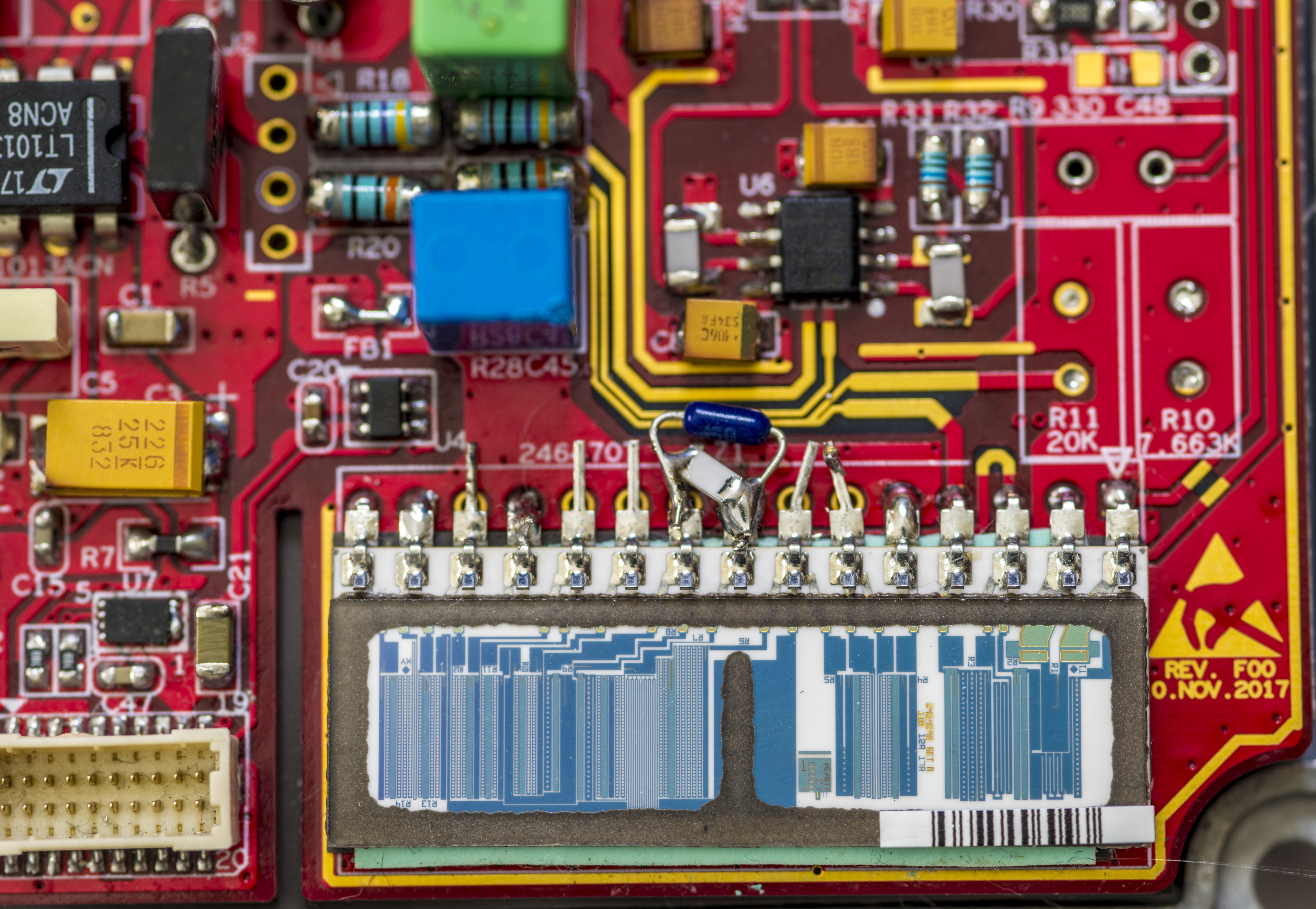
Image 65: xDevs.com FX

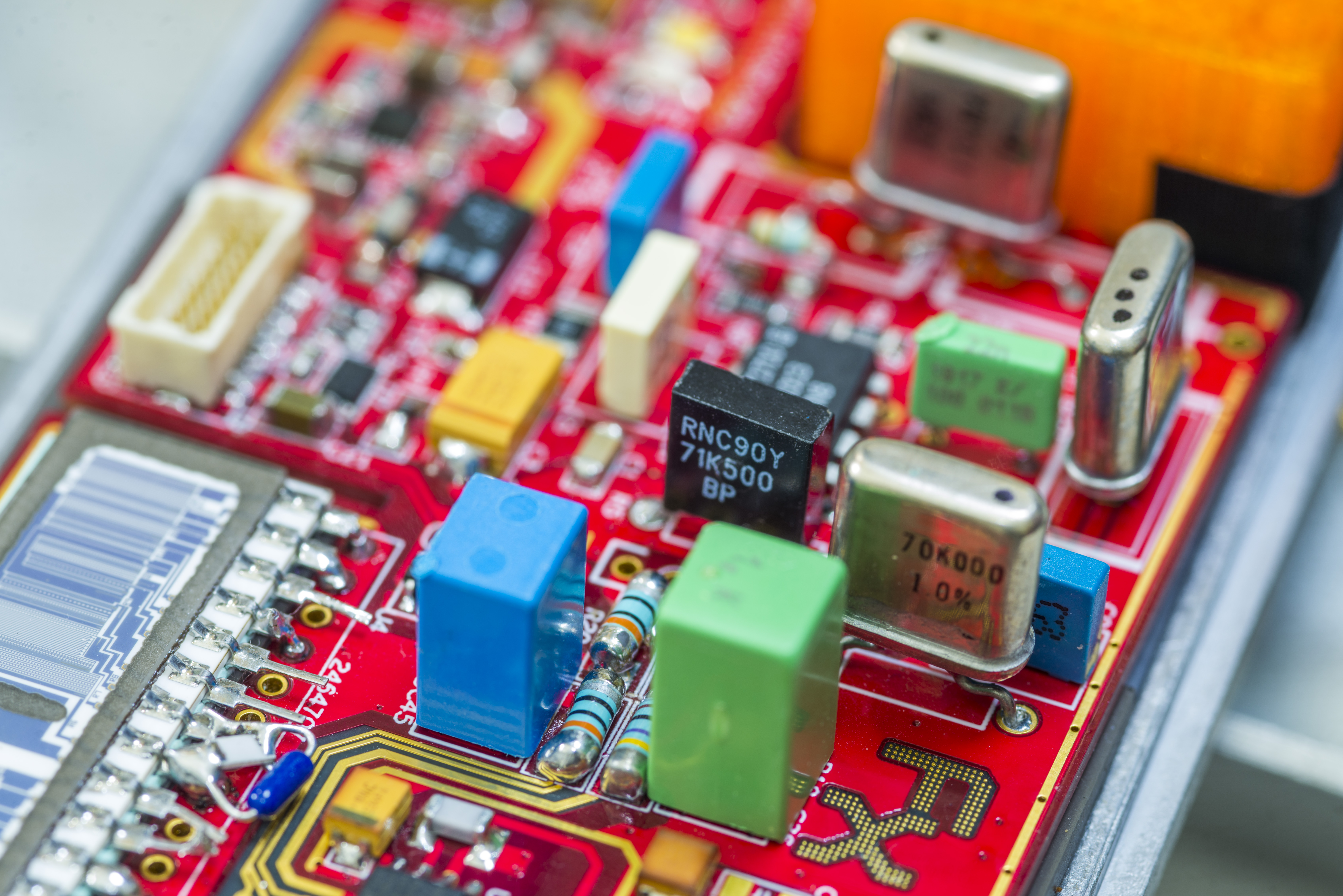
Image 66-68: xDevs.com FX
Image 69-71: xDevs.com FX
Unit is trimmed for temperature stability in enclosed airbath chamber, temperature controlled by Keithley 2510 and 40W watercooled TEC unit. Sensor used for temperature calibration is Honeywell HEL-705-U-0-12-00 1000 Ohm Platinum RTD. All connection between reference and measurement equipment are done with PTFE-insulated shielded cables.
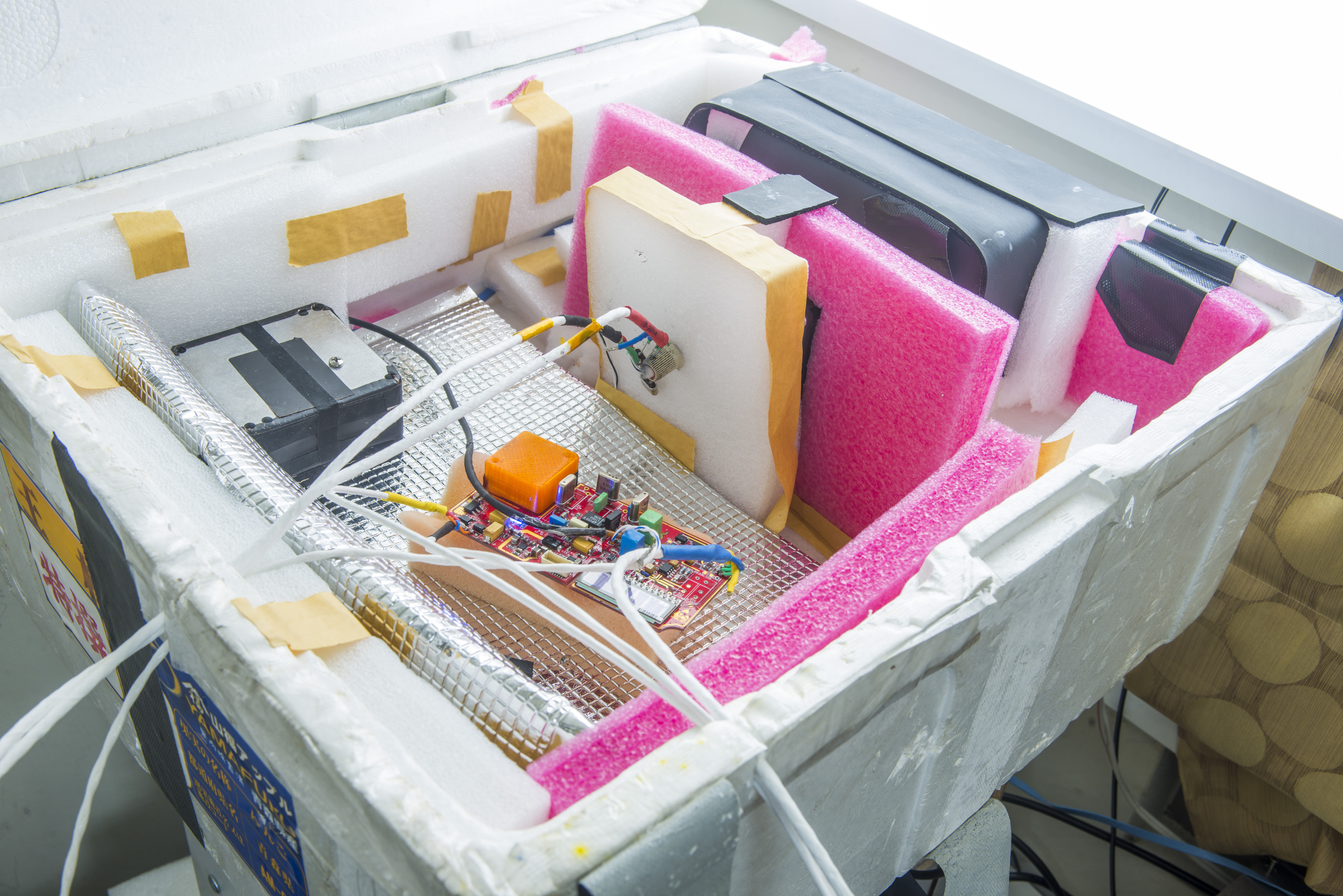
Image 72: xDevs.com FX


Image 73-74: xDevs.com FX

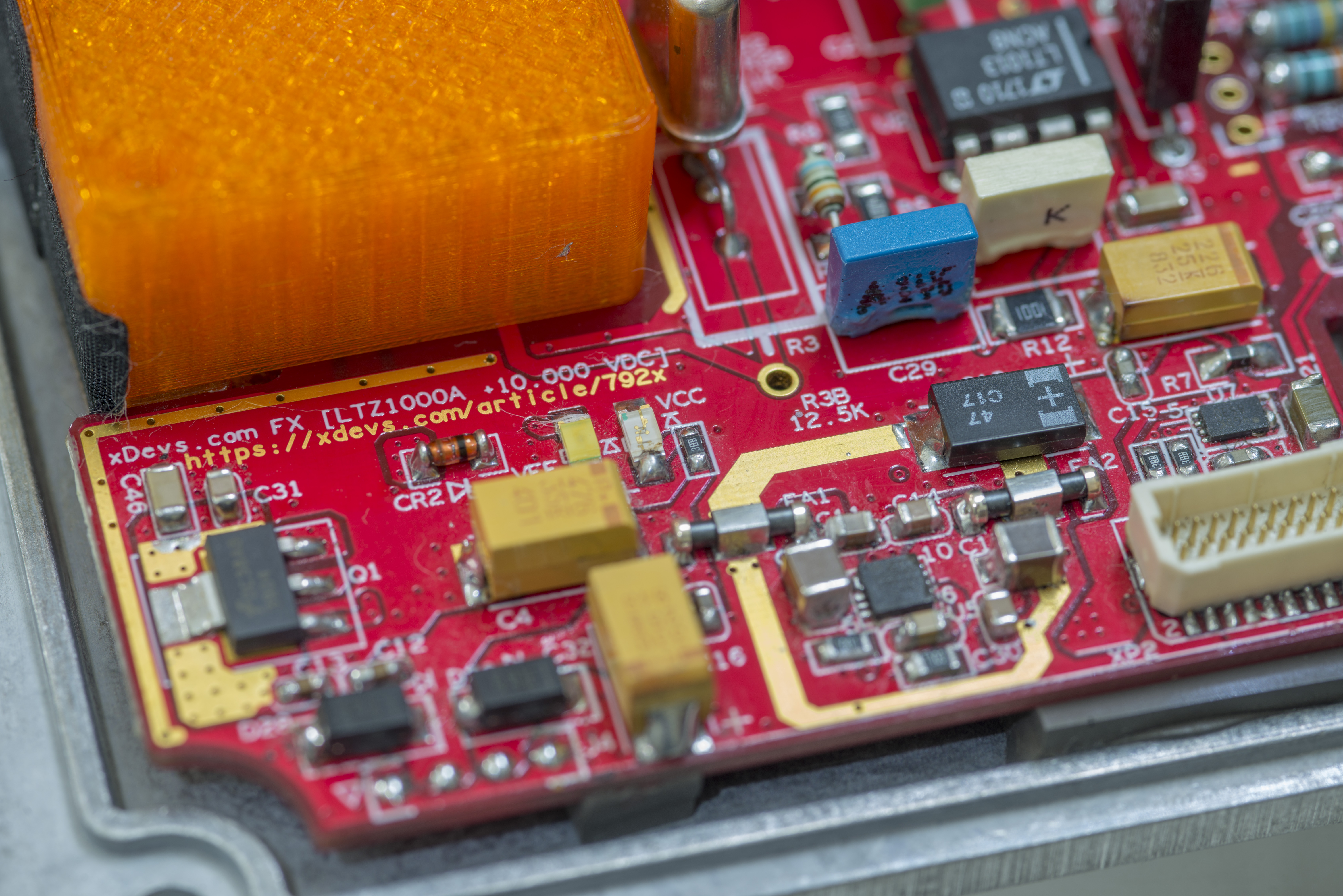
Image 75-76: xDevs.com FX
Packaged module:
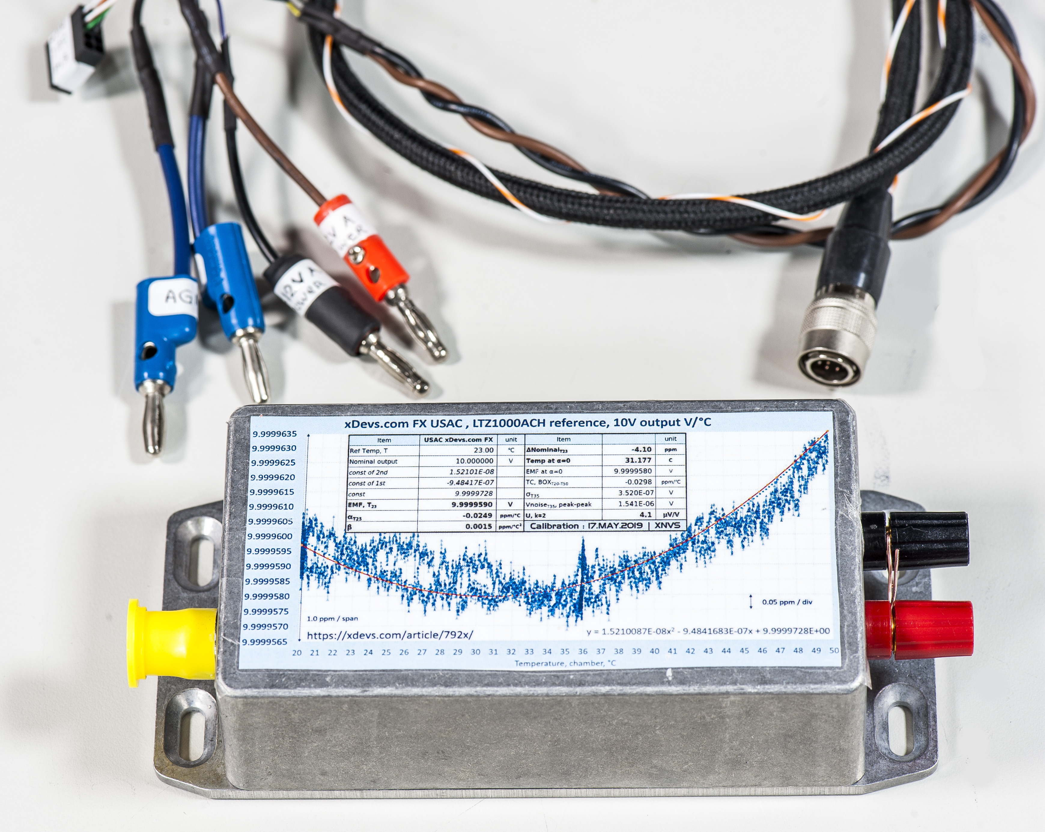
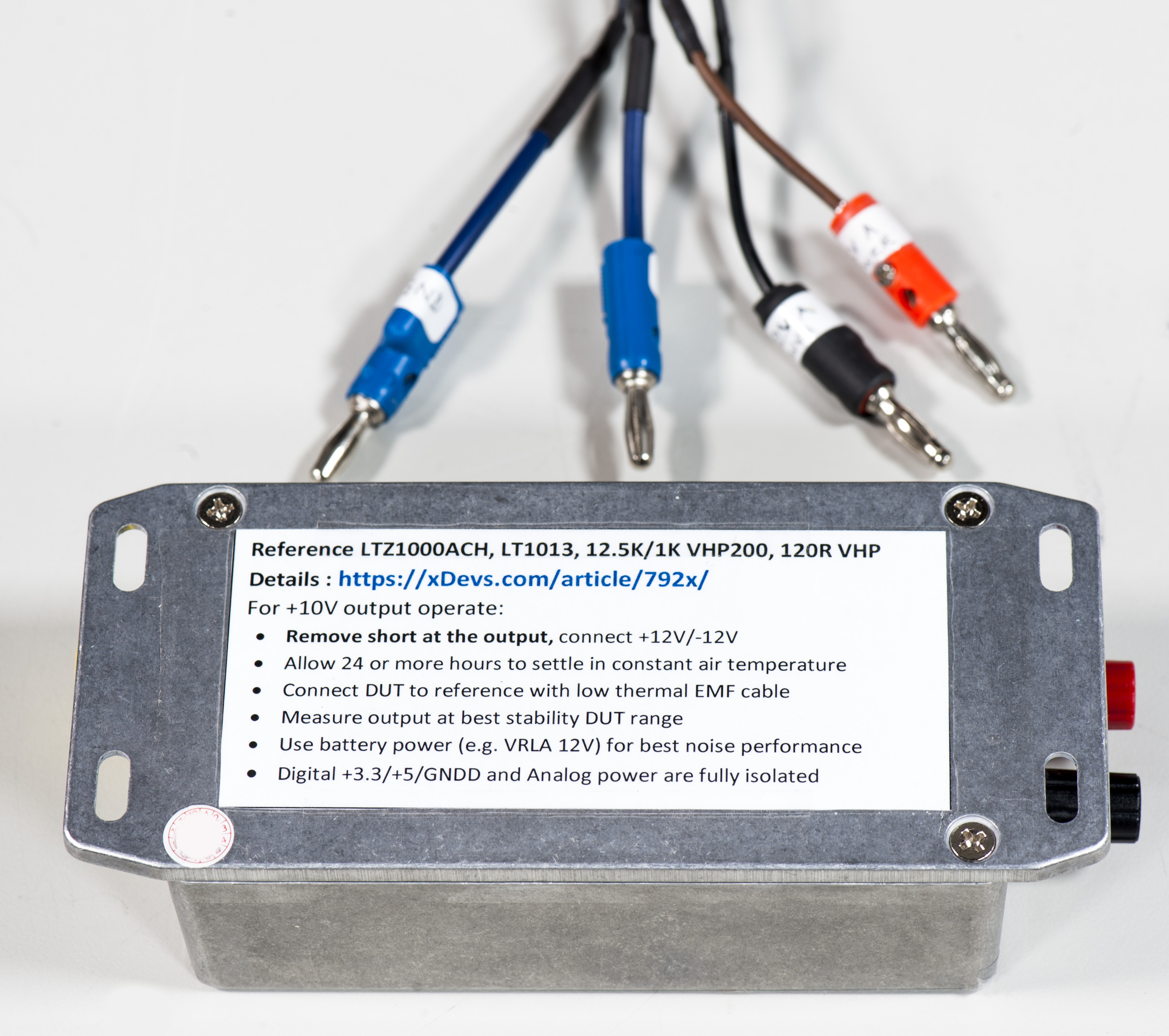
Image 77-78: xDevs.com FX
Cable to connect I2C data lines, Analog Power for reference, digital EEPROM and PCB temperature sensor is also provided.

Image 79: xDevs.com FX
Final test data is captured on packaged and complete module, shortly after warm-up time.
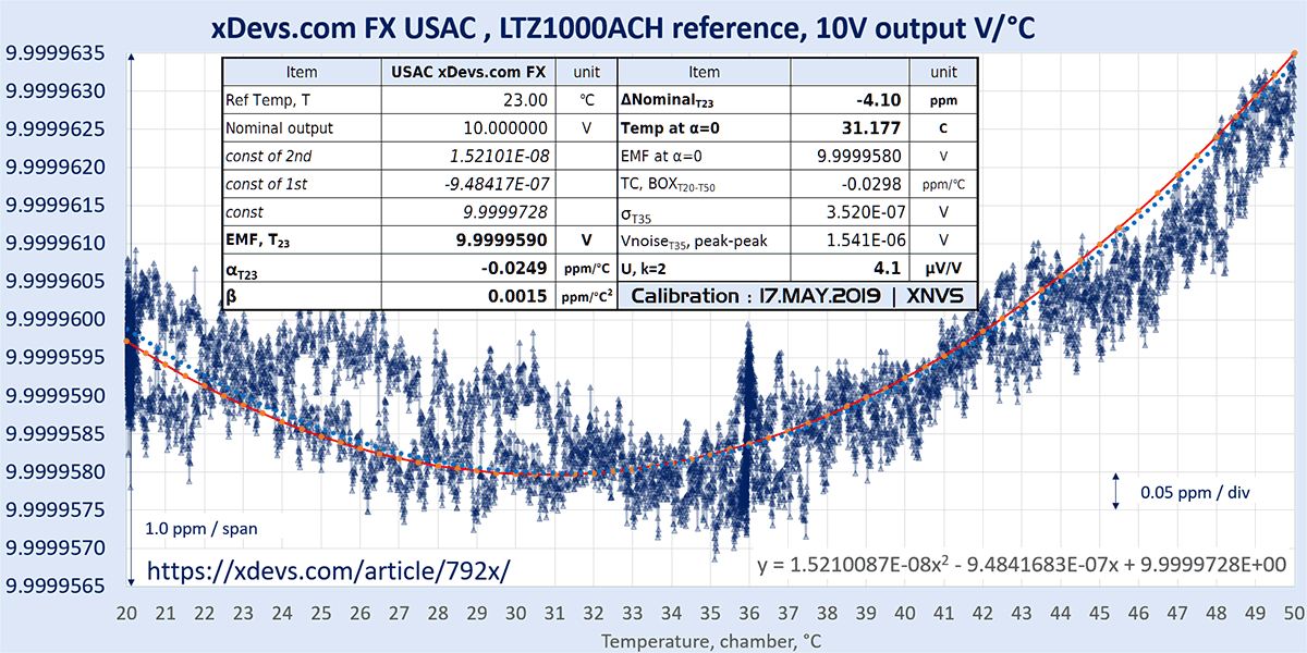
Image 80: xDevs.com FX
Same data in time domain representation:
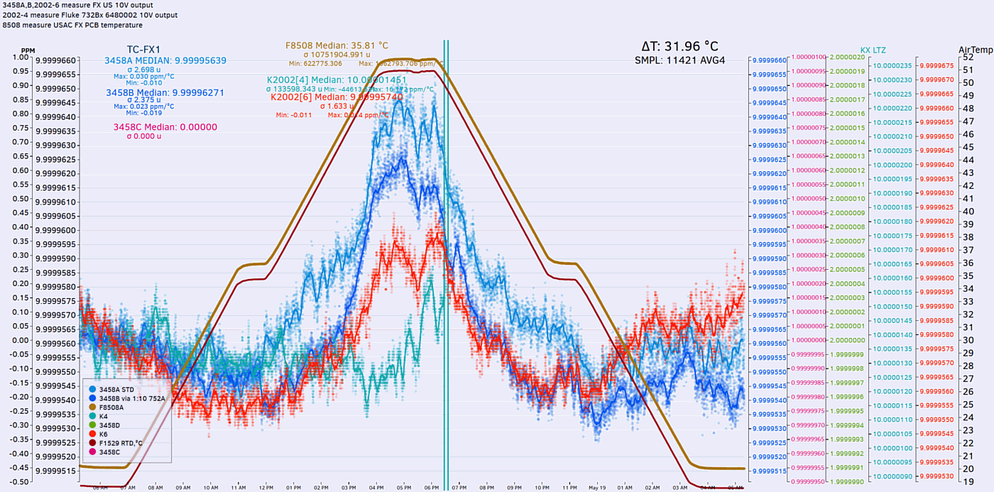
Image 81: xDevs.com FX
montemcguire FX reference
| US FX module | Parameter | Unit | Notes |
|---|---|---|---|
| Calibration date | 8/16/2020 | +23 °C ambient, by 3458AB | |
| Reference Temp T | 23.00 | °C | |
| Nominal output | 10.000000 | VDC | |
| 1st fit const | -1.18351e-6 | ||
| 2nd fit const | 1.41476e-8 | ||
| Gain const | 9.9999992 | VDC | |
| EMF, T23 | 9.9999795 | VDC | |
| α T23 | -0.0533 | ppm/K | |
| β | 0.0014 | ppm/K2 | |
| ΔT23 | -2.05 | ppm | Offset from nominal |
| Temp at α=0 | 41.827 | °C | |
| EMF at α=0 | 9.9999745 | VDC | |
| TC, BOX, T20-50 | -0.066 | ppm/K | |
| σT35 | 0.363 | µV | |
| Vnoise T35 | 2.174 | µVpk-pk | 0.1 – 10 Hz band |
| U, k=2 | sdev*3+refnf | µV/V | Within 24 hours, prior to shipping |

dr.diesel FX reference
chriswebb FX reference
PeLuLe A FX reference
PeLuLe B FX reference
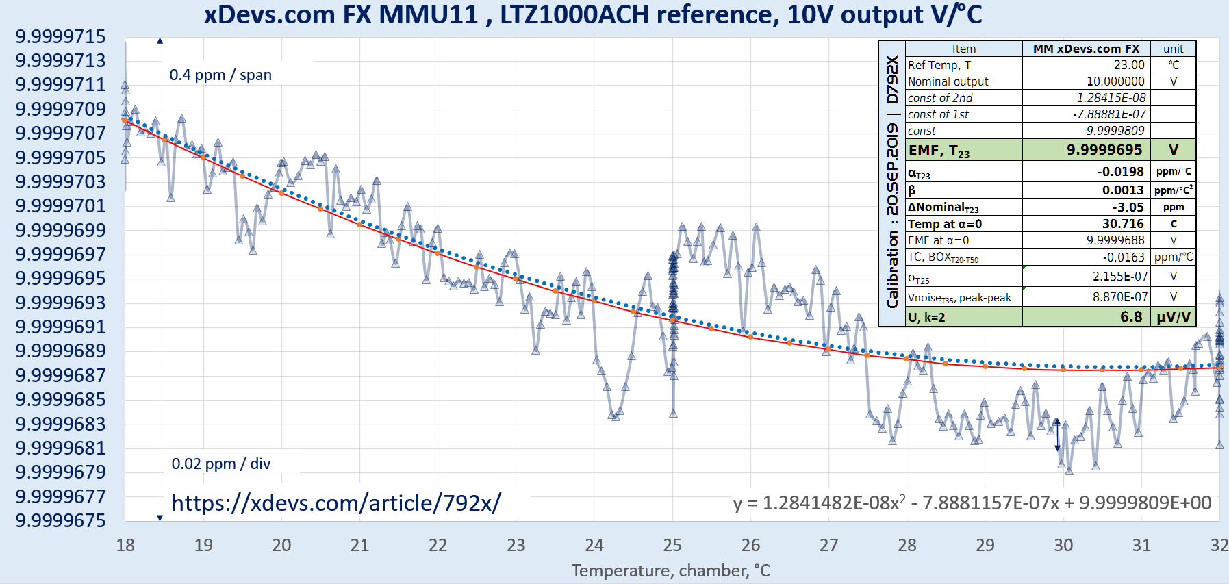
ManateeMafia FX reference
This unit is special version, with 4-wire copper only terminals output, aimed to use as stable current source as well as voltage source.
| MM FX module | Parameter | Unit | Notes |
|---|---|---|---|
| Calibration date | 9/20/2019 | +23 °C ambient, by 3458AB | |
| Reference Temp T | 23.00 | °C | |
| Nominal output | 10.000000 | VDC | |
| 1st fit const | 1.284148e-8 | ||
| 2nd fit const | -7.888115e-7 | ||
| Gain const | 9.9999809 | VDC | |
| EMF, T23 | 9.9999695 | VDC | |
| α T23 | -0.0198 | ppm/K | |
| β | 0.0013 | ppm/K2 | |
| ΔT23 | -3.05 | ppm | Offset from nominal |
| Temp at α=0 | 30.716 | °C | |
| EMF at α=0 | 9.9999688 | VDC | |
| TC, BOX, T20-50 | -0.0163 | ppm/K | |
| σT35 | 0.216 | µV | |
| Vnoise T35 | 0.887 | µVpk-pk | 0.1 – 10 Hz band |
| U, k=2 | sdev*3+refnf | µV/V | Within 24 hours, prior to shipping |
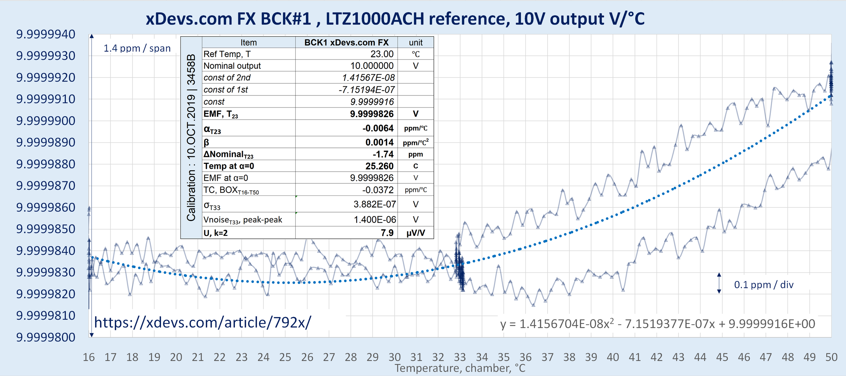
bck FX 1 reference
| bck1 FX module | Parameter | Unit | Notes |
|---|---|---|---|
| Calibration date | 10/10/2019 | +23 °C ambient, by 3458B | |
| Reference Temp T | 23.00 | °C | |
| Nominal output | 10.000000 | VDC | |
| 1st fit const | -7.15194e-7 | ||
| 2nd fit const | 1.41567e-8 | ||
| Gain const | 9.9999916 | VDC | |
| EMF, T23 | 9.9999826 | VDC | |
| α T23 | -0.0064 | ppm/K | |
| β | 0.0014 | ppm/K2 | |
| ΔT23 | -1.74 | ppm | Offset from nominal |
| Temp at α=0 | 25.26 | °C | |
| EMF at α=0 | 9.9999826 | VDC | |
| TC, BOX, T20-50 | -0.0372 | ppm/K | |
| σT35 | 0.388 | µV | |
| Vnoise T35 | 1.400 | µVpk-pk | 0.1 – 10 Hz band |
| U, k=2 | sdev*3+refnf | µV/V | Within 24 hours, prior to shipping |
bck FX 2 reference
| bck2 FX module | Parameter | Unit | Notes |
|---|---|---|---|
| Calibration date | 10/10/2019 | +23 °C ambient, by 3458B | |
| Reference Temp T | 23.00 | °C | |
| Nominal output | 10.000000 | VDC | |
| 1st fit const | -1.33718e-6 | ||
| 2nd fit const | 1.521475e-8 | ||
| Gain const | 9.9999882 | VDC | |
| EMF, T23 | 9.9999655 | VDC | |
| α T23 | -0.0637 | ppm/K | |
| β | 0.0015 | ppm/K2 | |
| ΔT23 | -3.45 | ppm | Offset from nominal |
| Temp at α=0 | 43.944 | °C | |
| EMF at α=0 | 9.9999588 | VDC | |
| TC, BOX, T16-50 | -0.0445 | ppm/K | |
| σT35 | 0.615 | µV | |
| Vnoise T35 | 2.700 | µVpk-pk | 0.1 – 10 Hz band |
| U, k=2 | sdev*3+refnf | µV/V | Within 24 hours, prior to shipping |

CalMachine FX reference
| CM FX module | Parameter | Unit | Notes |
|---|---|---|---|
| Calibration date | +23 °C ambient, by 3458AB | ||
| Reference Temp T | 23.00 | °C | |
| Nominal output | 10.000000 | VDC | |
| 1st fit const | |||
| 2nd fit const | |||
| Gain const | VDC | ||
| EMF, T23 | VDC | ||
| α T23 | ppm/K | ||
| β | ppm/K2 | ||
| ΔT23 | ppm | Offset from nominal | |
| Temp at α=0 | °C | ||
| EMF at α=0 | VDC | ||
| TC, BOX, T20-50 | ppm/K | ||
| σT35 | µV | ||
| Vnoise T35 | µVpk-pk | 0.1 – 10 Hz band | |
| U, k=2 | sdev*3+refnf | µV/V | Within 24 hours, prior to shipping |
zucca FX reference
Final assembled reference, ready for use as working standard
Here is finally assembled DC Voltage reference, reusing Fluke 792A Power Pack to provide battery power to the xDevs.com FX 10V module, as well as charge battery. DC reference outputs are full 4-wire kelvin connection with Low Thermal posts, with current source/sink capability over 20 mA. In normal operation SENSE HI and SENSE LO posts should be shorted to CURR HI / LO posts to close the output feedback loop.
Charger / power supply for 792A AC/DC transfer unit is also allowed independently, using original LEMO port and cable.
Back and side of the unit as fully shielded, just like original Fluke 792A, no alterations made on these sides.


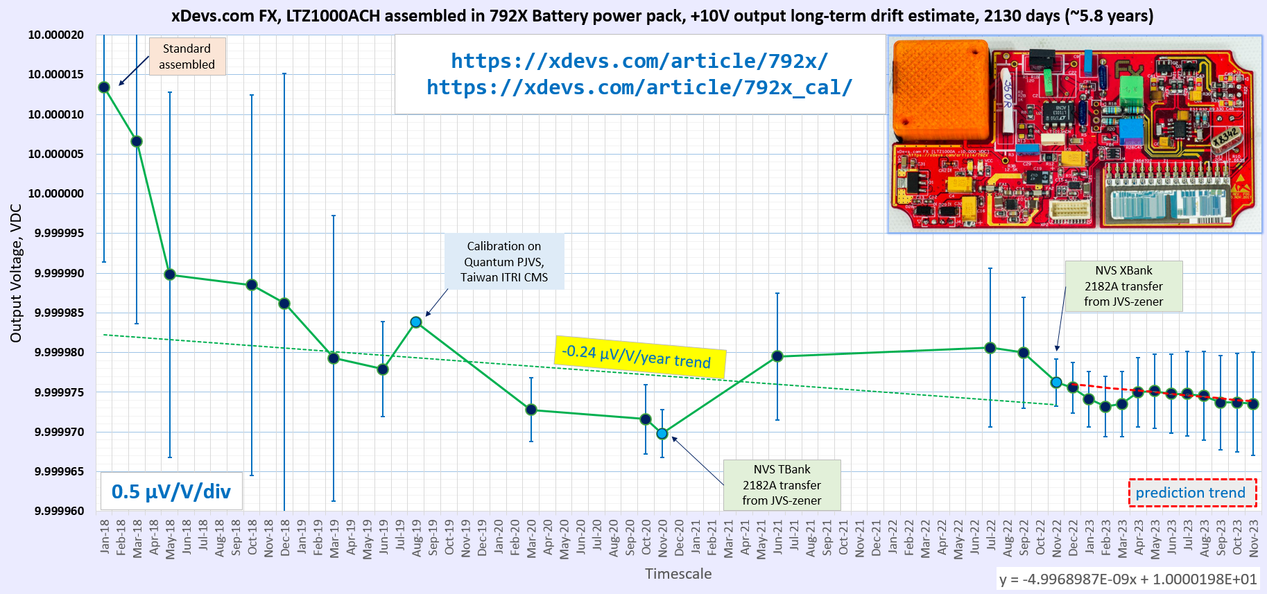
This DC reference is constantly powered after assembly on since January 2018. It’s current value as of May 27, 2018 is +9.99997983 V ±1.0 ppm
Calibration results and performance tracking
This reference was calibrated by Taiwan’s National Measurements Institute in August 2019 . NIST SRI6000 PJVS system was used as a primary traceable reference during that key calibration.
Calibration report for xDevs.com 792× 10V DC Voltage Reference, August 8 2019, Taiwan NMI
Calibration report for xDevs.com 792× 10V DC Voltage Reference, March 3 2020, TMI Lab, FL, USA
Accredited external calibration history so far:
| xDevs.com 792X | Calibration Date | Assigned value | Uncertainty | Shift | Shift/year | Days |
| TW NMI calibration (NIST PJVS Quantum system) | 08/08/2019 | 9.9999838 VDC | 0.03 ppm | -1.82 ppm | -1.16 ppm | +573 |
| TMI calibration | 03/03/2020 | 9.9999751 VDC | 0.39 ppm | -2.69 ppm | -1.26 ppm | +208 |
Here we have all list of traceable calibrations to other references of similar grade, and estimate annual stability of finished 792X project.
| Calibration date | Method | Measurement result | Uncertainty | Conditions | Accredited | Δ to predicted |
|---|---|---|---|---|---|---|
| January 2018 | Direct 3458A+3458B, K2002 measurement | +10.0000134 V | ±2.20 ppm | Battery power | No | No data |
| March 2018 | Direct 3458B | +10.0000066 V | ±2.30 ppm | Battery power | No | No data |
| May 2018 | Direct 3458A | +9.99998983 V | ±2.30 ppm | Battery power | No | No data |
| October 2018 | Direct 3458B | +9.9999885 V | ±2.40 ppm | Battery power | No | No data |
| December 2018 | Direct 3458A, corrected | +9.9999862 V | ±2.90 ppm | Battery power | No | No data |
| March 2019 | Direct 3458s,2002 | +9.9999793 V | ±1.80 ppm | AC power | No | No data |
| June 2019 | K155 vs F732B SI | +9.9999779 V | ±0.60 ppm | Battery power | No | No data |
| August 2019 | PJVS SRI6000 transfer @ CMS ITRI | +9.99998382 V | ±0.03 ppm | Battery power | NMI | Zero reference |
| March 2020 | HP34420A vs F732B | +9.9999728 V | ±0.40 ppm | Battery power | Yes | No data |
| October 2020 | 3458A transfer from 732B | +9.9999716 V | ±0.44 ppm | Battery power | No | No data |
| November 2020 | JJ-referenced D4910 array | +9.9999698 V | ±0.30 ppm | Battery power | No | 1st reference |
| September 2021 | NLab VBank system | +9.9999800 V | ±0.70 ppm | AC Power | No | No data |
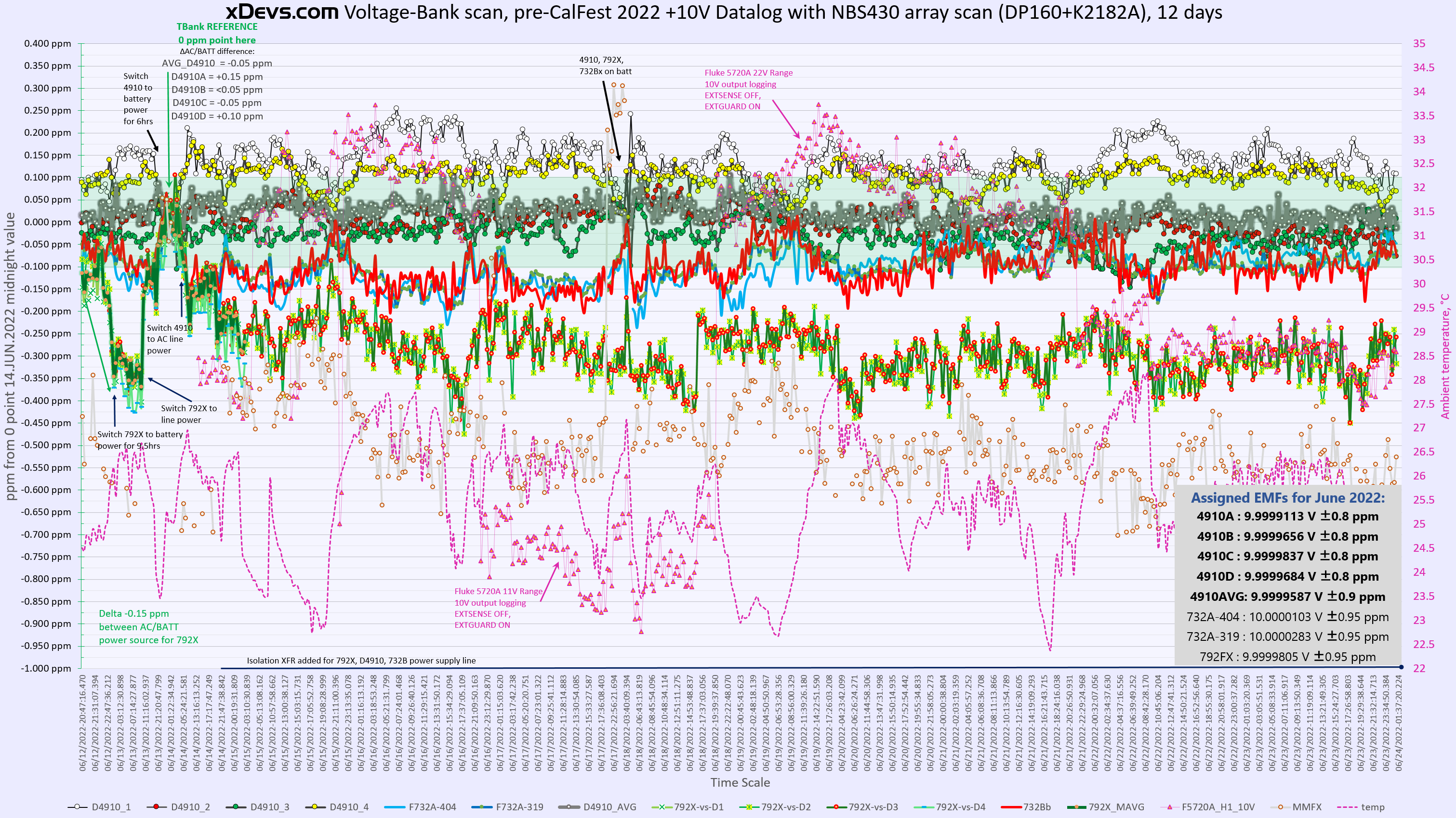
| June 2022 | D4910 TBank system | +9.9999795 V | ±0.80 ppm | Battery Power | No | No data |
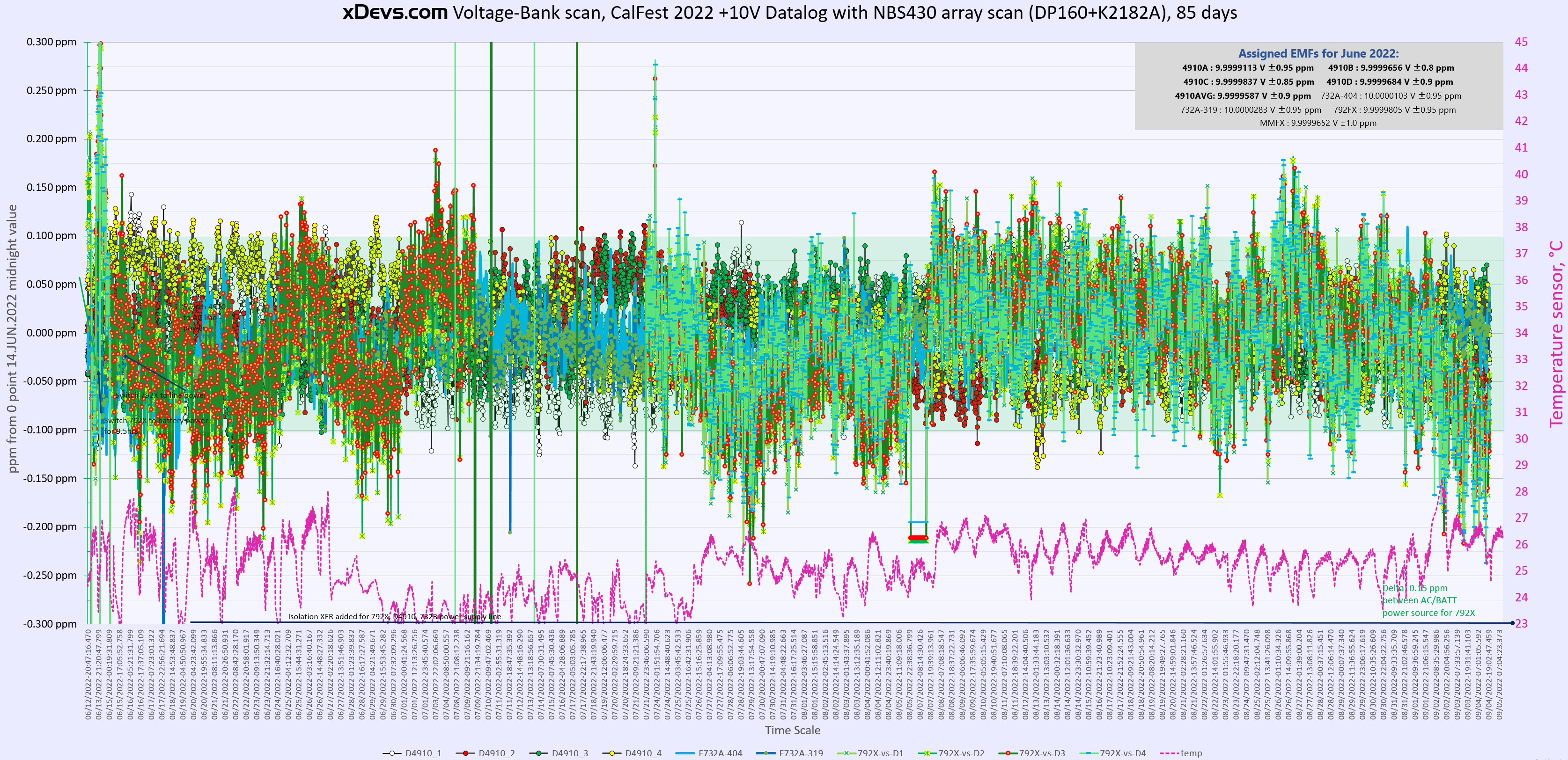
| July 2022 | D4910 TBank | +9.9999806 V | ±1.00 ppm | Battery Power | No | No data |
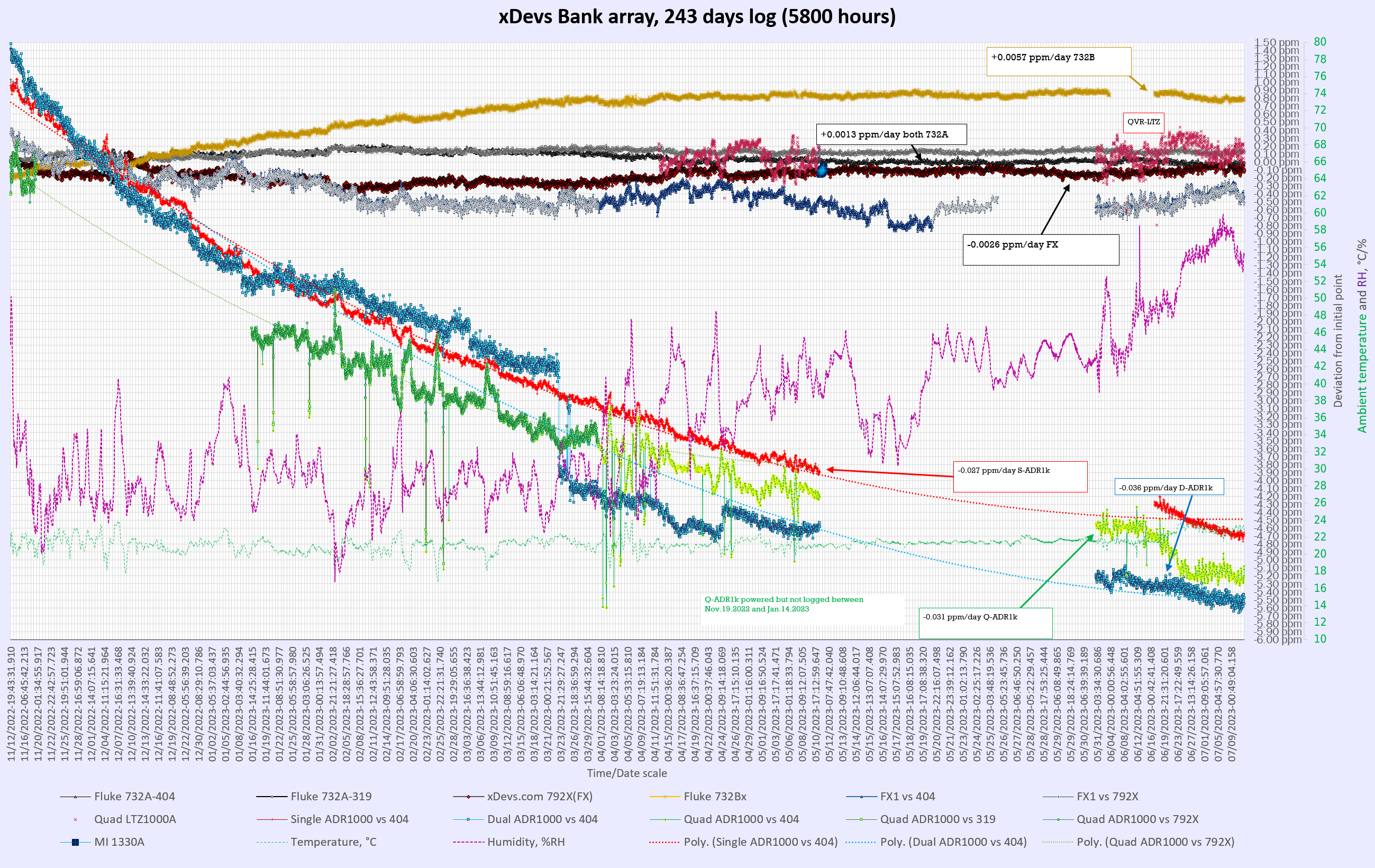
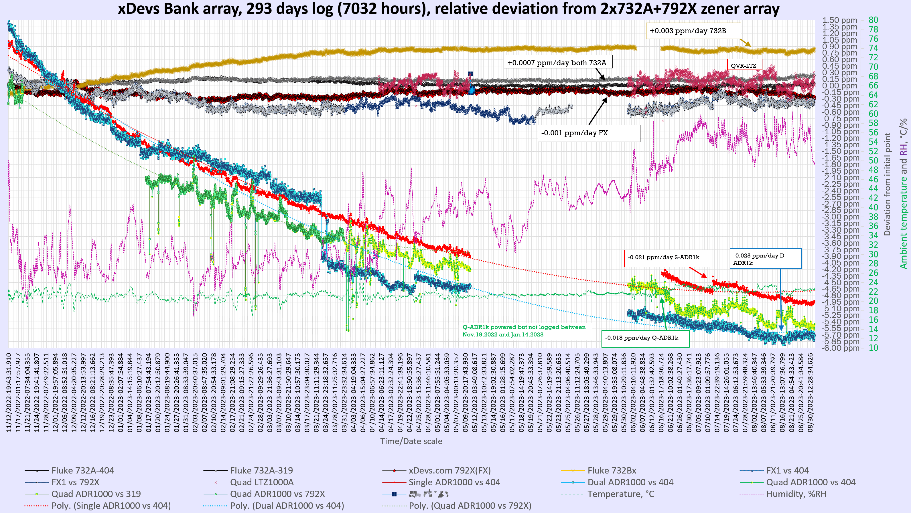
| November 2022 | JJ-referenced D4910 XBank | +9.99997612 V | ±0.30 ppm | Line Power | No | 2nd reference, +0.42 µV/V |
| December 2022 | X-Bank array + nVM | +9.99997557 V | ±0.32 ppm | Line power | No | 0.04 µV/V |
| January 2023 | X-Bank array + nVM | +9.99997414 V | ±0.35 ppm | Line power | No | 0.16 µV/V |
| February 2023 | X-Bank array + nVM | +9.99997320 V | ±0.38 ppm | Line power | No | 0.24 µV/V |
| March 2023 | X-Bank array + nVM | +9.99997353 V | ±0.41 ppm | Line power | No | 0.18 µV/V |
| April 2023 | X-Bank array + nVM | +9.99997500 V | ±0.44 ppm | Line power | No | 0.02 µV/V |
| May 2023 | X-Bank array + nVM | +9.99997514 V | ±0.47 ppm | Line power | No | -0.01 µV/V |
| June 2023 | X-Bank array + nVM | +9.99997482 V | ±0.50 ppm | Line power | No | 0.00 µV/V |
| July 2023 | X-Bank array + nVM | +9.99997481 V | ±0.53 ppm | Line power | No | -0.01 µV/V |
| August 2023 | X-Bank array + nVM | +9.99997453 V | ±0.56 ppm | Line power | No | -0.01 µV/V |
| September 2023 | X-Bank array + nVM | +9.99997369 V | ±0.59 ppm | Line power | No | 0.05 µV/V |
| October 2023 | X-Bank array + nVM | +9.99997373 V | ±0.62 ppm | Line power | No | 0.03 µV/V |
| November 2023 | X-Bank array + nVM | +9.99997355 V | ±0.65 ppm | Line power | No | 0.03 µV/V |
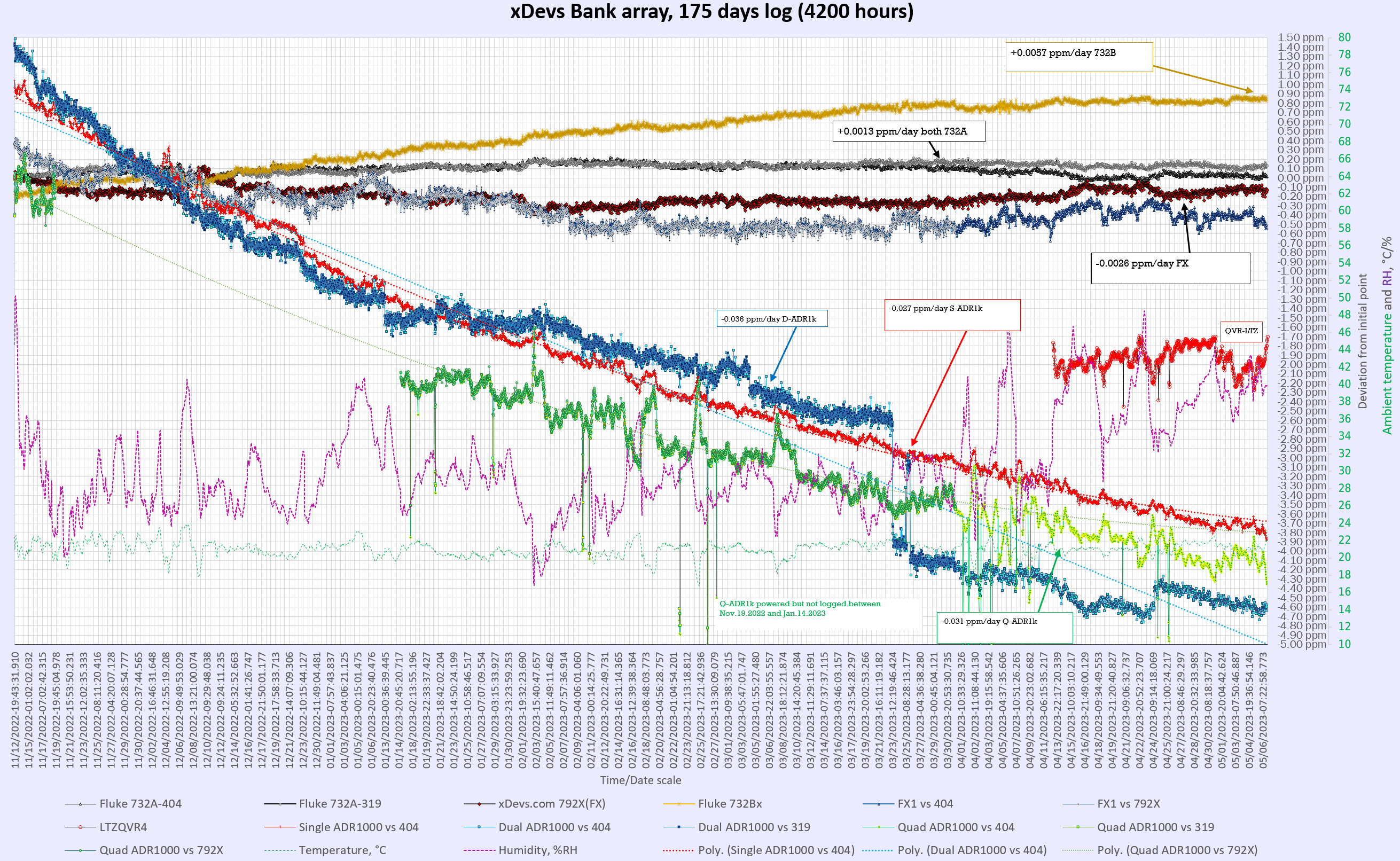
Drift of this custom LTZ1000A-based referenced in 1181 days between two JVS-referenced points in November 2022 and August 2019 is -0.77 ppm.
This translates into voltage drop at rate -0.238 ppm/year, which is pretty good for single-device zener reference that is being constantly powered.
Such long-term drift study also highlights importance of periodic calibrations with very good uncertainty, ideally directly referenced to quantum standards such as Josephson Voltage System with minimal amount of intermediate transfer standards or transportation. Table and chart in this section represent only condensed key summary of all the measurements and long-term data captured by xDevs.com members and in-house automation software. We have gigabytes of data points captured on this and other standards including commercial units like Fluke 732A/B, Datron 491x and others. Due to magnitude of sources used and complexity of such large dataset analysis with logistic challenges this data it is not available to public at this time.
One also can notice important evolution of our in-house voltage measurement and monitoring capability improvements over the years time span, which is also reflected in improved uncertainty of the points. Current setup is built around array of various zener standard, DataProof 160A low-thermal scanner , Keithley 2182A nanovoltmeter and in-house software implementing modified algorithm measuring matrix opposite polarity of each zener cell, heavily inspired by NIST/NBS Technical Note 430. All measurements are done in both polarities to cancel thermal EMF errors. Use of dedicated nanovoltmeter on most sensitive range instead of long-scale DMM such as HP3458A helps to remove the contribution of the meter’s tempco and noise from zener voltage result.
Cable assembly for 792A use.
Cable was packed better than most of the instruments from ebay, in double box with lot of wrap :)

Image 82: xDevs.com FX
Wire is PVC 0.2mm.sq noname, marked as 60227 IEC type.
CONSTRUCTION
Conductor: Plain annealed flexible stranded copper conforming to BS EN 60228, Class 5.
Insulation: PVC compound conforming to BS 7655-3.1 Type TI 3/ IEC 60227-1 Type PVC/E. Maximum conductor temperature in normal use 90°C.
Color: AMACO Standard Colors are: Black, Blue, Green/Yellow, Red, Yellow, White, Violet, Brown, Grey, Orange, Pink

Image 83: xDevs.com FX
LEMO FGG.2B 307 or a knockoff. I don’t see any markings on LEMO connector itself, but it does not look cheap or flimsy, so chances are these are legit.
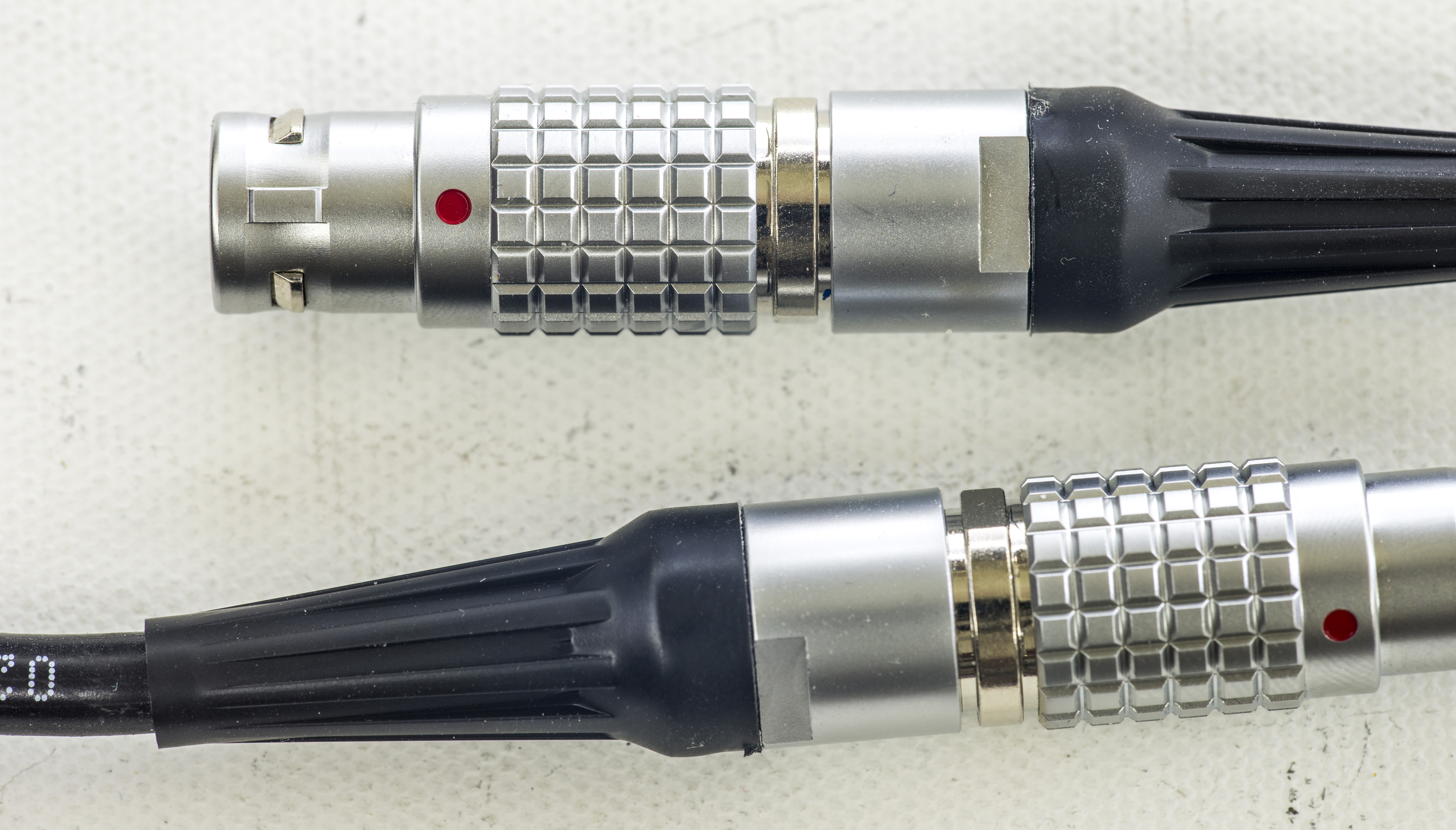
Image 84: xDevs.com FX
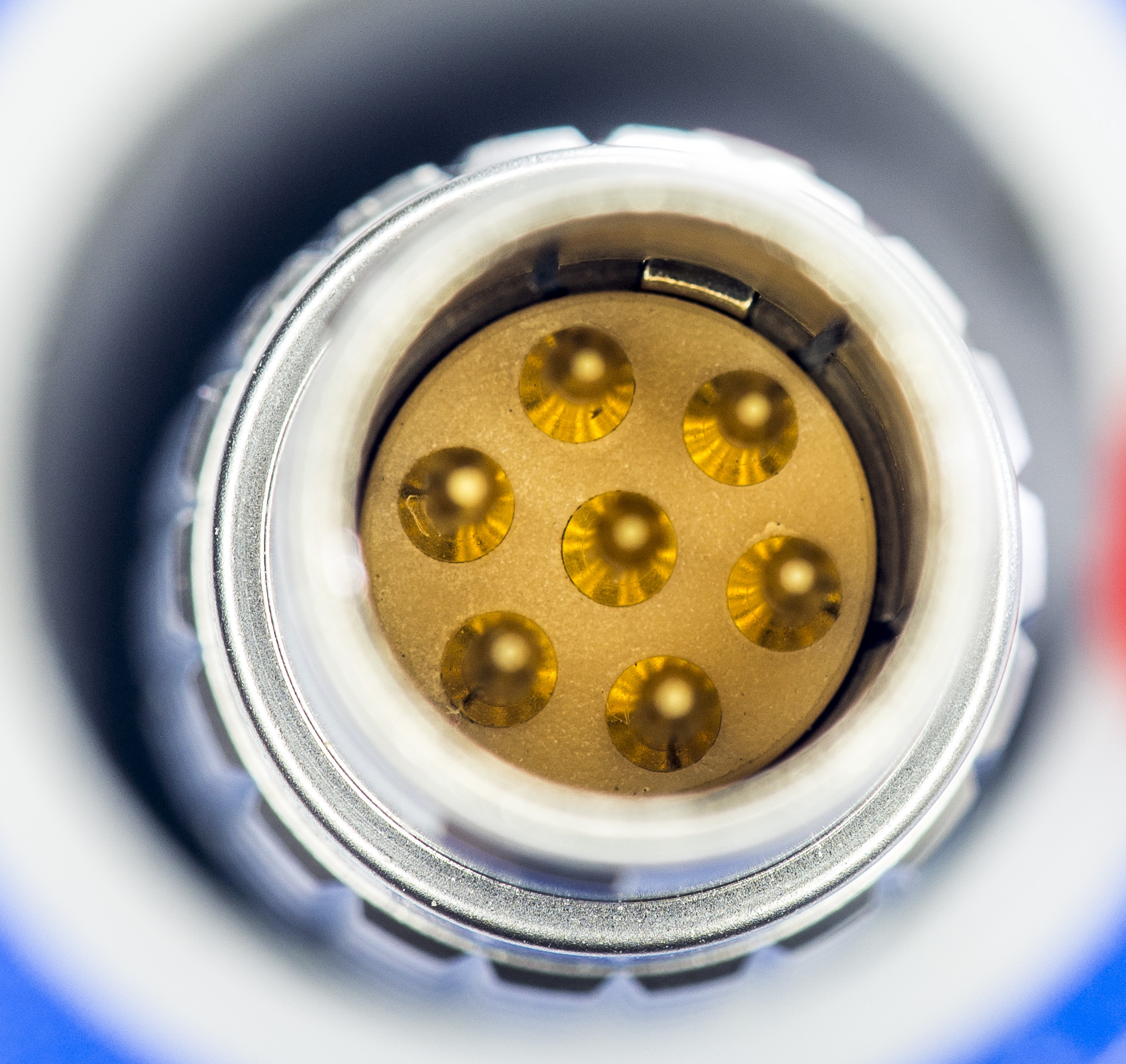
Image 85: xDevs.com FX
Bits and pieces.
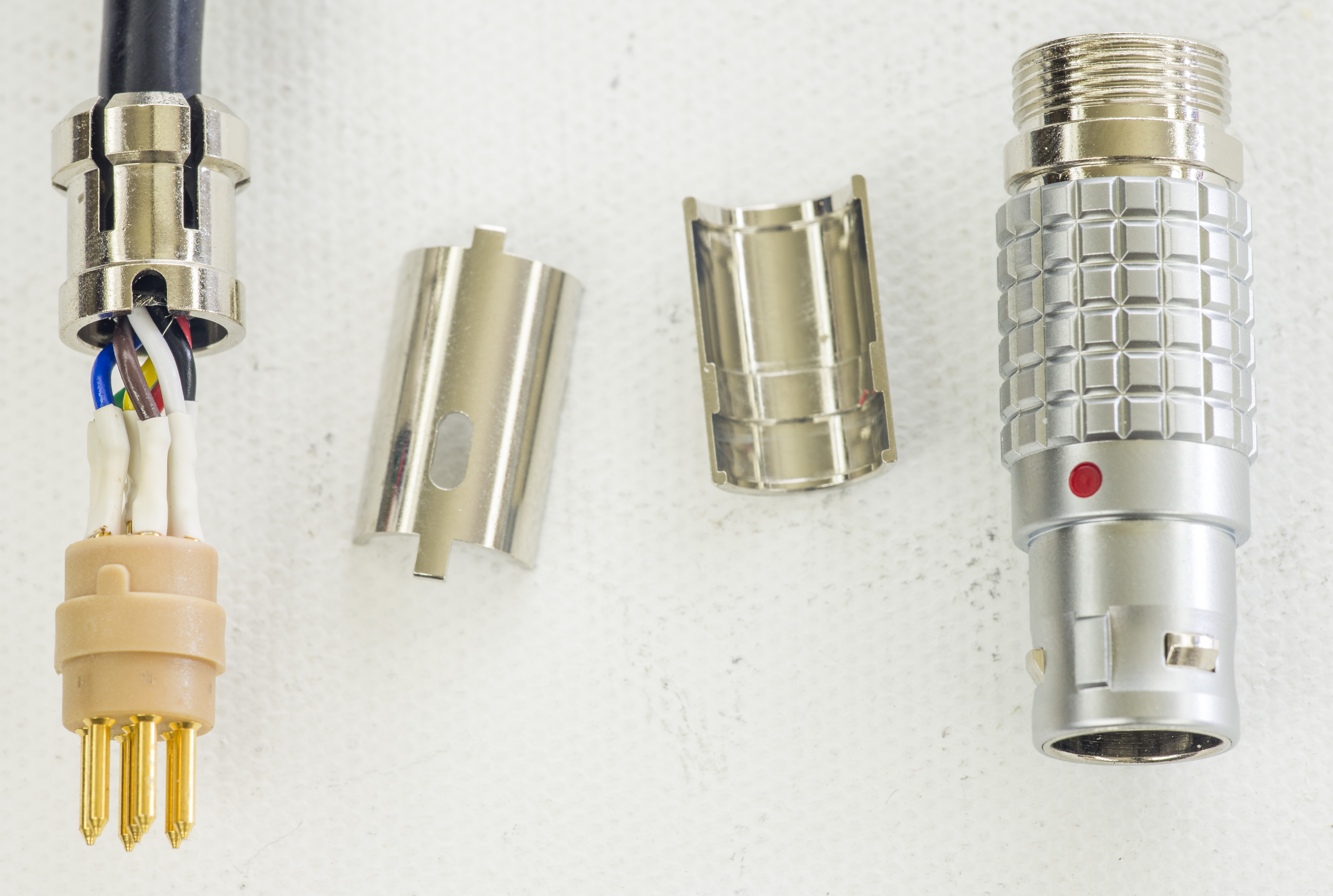
Image 86: xDevs.com FX
Overall not bad for $42.7 and free express shipping.
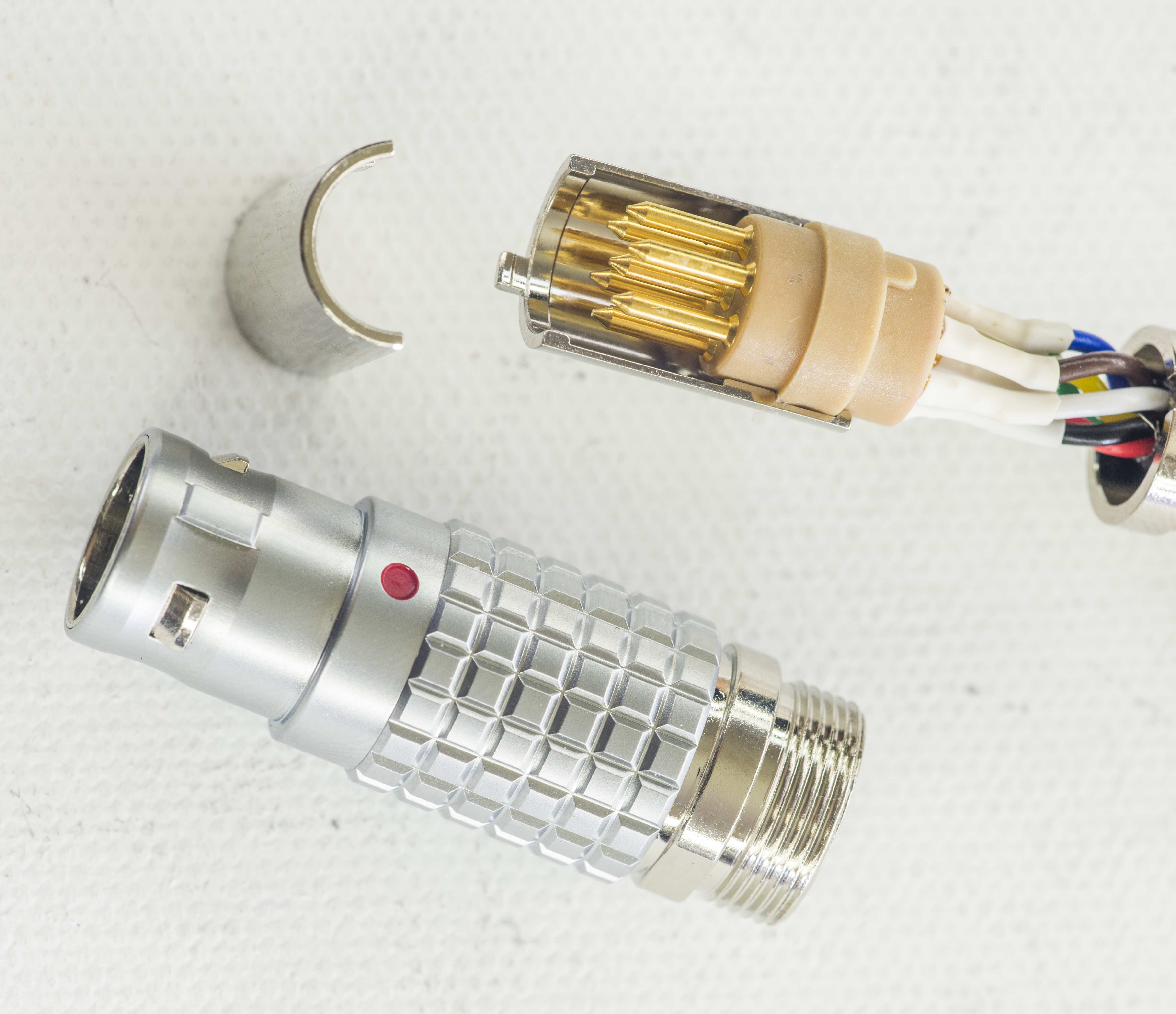
Image 87: xDevs.com FX
How they also have pairs of connectors, if I’m reading this lot description correctly. That’s is for connector+plug 2B series 306 is 33$ USD.
Summary
Let’s make a final count for funds spent.
| Linear Order | Qty | $USD/pcs | $Sum |
| LTZ1000ACH | 20 | 54.5 | 1090 |
| LT1013ACN | 10 | 4.75 | 47.5 |
| Vishay Precision Group P/N | Qty order | $USD/pcs | $Sum |
| Y6072120R000B9L | 25 pcs | 27 | 675 |
| Y006270K0000B9L | 25 pcs | 21 | 525 |
| Y607213K0000B9L | 5 pcs | 35 | 175 |
| Y60721K00000B9L | 5 pcs | 39 | 195 |
| Y5076V****BB9L (13K+1K) | 25 pcs | 55 | 1375 |
| Fluke 792A Power pack, parts | 1 unit | 2000 | 2000 |
| Calibration by JVS at Taiwan CMS ITRI, 2019 | 1 | 400 | 400 |
| Calibration by TMI Florida, 2020 | 1 | 400 | 400 |
| Calibration by D4910-JVS during CF2020 | 1 | 2000 | 2000 |
| Calibration by D4910-JVS during CF2022 | 1 | 2000 | 2000 |
| Total order cost | $11k USD | ||
As result resistor set for LTZ not using network is $143 USD and one using network is $124 USD. This numbers do include quantity discount bracket price. If one to order just one set, cost for it would be in excess of $170 USD. I’ve ordered more resistors than required for 10 units, to have ability in sorting for best tempco.
So PCBA build which would take normally just few hours for normal projects took nearly a week of time (2-4 hours each day) and required expensive (MSRP >10k $USD) and verified instrumentation to ensure required performance level.
Hope these efforts would help to better understand hidden icebergs and dangers big enough to sink a project in high-precision field, even for something as simple as direct voltage reference module.
Also real-time discussion about this article and related stuff is very welcome at our own xDevs.com IRC-chat server: xdevs.com (standard port 6010, channel: #xDevs.com). Web-interface for access mirrored on this page.
Projects like this are born from passion and a desire to share how things work. Education is the foundation of a healthy society - especially important in today's volatile world. xDevs began as a personal project notepad in Kherson, Ukraine back in 2008 and has grown with support of passionate readers just like you. There are no (and never will be) any ads, sponsors or shareholders behind xDevs.com, just a commitment to inspire and help learning. If you are in a position to help others like us, please consider supporting xDevs.com’s home-country Ukraine in its defense of freedom to speak, freedom to live in peace and freedom to choose their way. You can use official site to support Ukraine – United24 or Help99. Every cent counts.
Modified: April 1, 2026, 9:02 a.m.