- Intro
- Disclaimer
- Important notes
- Test procedure and setup
- Interesting results
- Results from direct measurements
- Brand new VPG BMF batch test 2018
- Scanner setup
- Results from scanner setup
- Tests 2020
- Resistance value calculator
Introduction
In instrumentation and sensor/analog design stability of used electronic components can depend on many factors. Key factors can be such as power, temperature, pressure and humidity. One of most visible effects is related to temperature, as every component has specified operational range of temperatures, and lot of electrical circuit properties change with actual temperature. Even simple passive component, such as resistor is affected by temperature. Higher temperature makes electrons move with different speed, making total resistance change. Rate of this change per fixed temperature value is called temperature coefficient of resistance.
This coefficient, also often referred as “alpha” (α) and “beta” (β) constants reflects the resistance change factor per 1 degree of temperature change. Different materials used as resistor elements have a certain specific resistance at standard 20°C, and rate of resistance change to temperature by certain amounts. For pure metals, TCR is a positive number, meaning that resistance increases with increasing temperature. Some other elements, such as carbon, silicon, and germanium have negative TCR, meaning that resistance decreases with increasing temperature.
Metal alloys can have overall TCR very close to zero, meaning that the resistance stays stable within specific temperature variation. However overall TCR still depends a lot on construction of resistor, used packaging method and even resistance element shape and terminal configuration. Even stress introduced to precision resistance wire can make otherwise stable resistance become mediocre due to thermal coefficient. Making resistor trimmed some specific value, let’s say 10.00000 KΩ is not that difficult, but making same resistor with very low temperature coefficient and long-term stability is much bigger and expensive challenge.
Disclaimer
Redistribution and use of this article or any images or files referenced in it, in source and binary forms, with or without modification, are permitted provided that the following conditions are met:
- Redistributions of article must retain the above copyright notice, this list of conditions, link to this page (/article/tcr_test/) and the following disclaimer.
- Redistributions of files in binary form must reproduce the above copyright notice, this list of conditions, link to this page (/article/tcr_test/), and the following disclaimer in the documentation and/or other materials provided with the distribution, for example Readme file.
All information posted here is hosted just for education purposes and provided AS IS. In no event shall the author, xDevs.com site, or any other 3rd party, be liable for any special, direct, indirect, or consequential damages or any damages whatsoever resulting from loss of use, data or profits, whether in an action of contract, negligence or other tortuous action, arising out of or in connection with the use or performance of information published here.
If you willing to contribute or add your experience regarding resistance measurements or provide extra feedback, you can do so following these simple instructions
Important notes
Good analog electronics designers who need accurate signal processing must pay attention to resistor temperature coefficient, and often this value is more important then resistance accuracy tolerance itself. And since better TCR resistors (more stable ones) are usually also much more expensive, it’s important to know and be able to measure TCR. This allow to calculate error budget of design and factor in possible resistance variations, to ensure circuit is working correctly under possible temperature variation.
Resistor manufacturers are often use great lengths of specmanship in their datasheets. Specmanship here referred to careful wording of performance specifications, to give false expectations of better performance that really achievable/measureable in real world application. There are some ways to detect specmanship, like use of terms “typical” or “usual”. “Typical” or “best” specifications may provide some information, but these values offer no guarantee that the resistor you buy is anyhow “typical” or even capable of providing the “best” performance as listed. Also “typical” does not indicate of test conditions or period when measurements were taken.
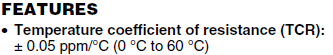
Here is just one fine example of what is meant by smart specmanship, listed in datasheet of very good and expensive Vishay Precision Group VHP203, which is hermetically sealed precision resistor.

We are welcomed by big eye-catching title promising us TCR of 0.05 ppm/°C, with bold underlined text. Hard to miss that one, where do we insert money to get it?
Note, there is no “Typical” or “best” word used either, leading us to assumption that all resistors have 0.05 ppm/°C performance. Maybe more fine text reveals worse specification for TCR?
Nope, feature list shows TCR value ±0.05 ppm/°C now, first item in list, in bold font again. Maybe actual graph shows more detail, surely?
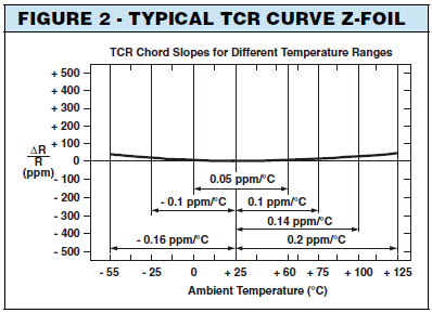
Still according to graph performance is stellar, worsening just to little +0.2 ppm/°C over +25 °C to +125 °C range. Here we catch first time mention of “Typical” however. Not a word how typical is the result across the random batch. Is it performance of one resistor out of 100? Or the median value out of 1000 resistors? Very interesting.
Resistors that were aged or conditioned before measurement can also show better results, but that will not indicate out of the box brand new resistor performance by any means. For precision designs and calibration applications, only worst-case or guaranteed performance maximum specifications are required that include all natural variations in the product.
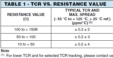
And only little Table 1 (give the VPG credit, it is shown on first page though) does reveal desired maximum TCR range. For main range of resistance values from 100 Ω to 150 KΩ we have MAX SPREAD value for TCR, which is ±2.0 ppm, added to “Typical TCR”. So in worst case random VHP203 resistor will have temperature coefficient at -2.2 ppm/°C or +2.2 ppm/°C and it will be still in manufacturer spec. You will not find this number however anywhere else in the model title or marketing documentation info from the VPG. If you really want guaranteed ±0.05 ppm/°C there is friendly note to contact VPG. Be sure to prepare the bank account, because while you may want just one resistor, you will pay for all batch to make for selection of the low-TCR resistor unit.
To be precise, “Typical” specifications are totally fine if they accompanied by a guaranteed specification. But if only “typical” values are given, then you don’t have means to know actual worst-case specification of the unit! And maximum guaranteed specifications are not listed for some of VPG models, such as VHD200 have only “typical values”, not the maximum!
During work on this article, specific resistance elements were evaluated under specific conditions and equipment we have in reach. It would take extensive and time-consuming engineering analysis (and whole lot more expensive samples) to make accurate predictions of performance margins, that could be in theory applied to all units being produced. However data required for such rely on deep understanding of proprietary process involved in manufacturing, testing and packaging of the resistors, and only manufacturer has access to such information. Unless you are major player on the market that order thousands of resistors every month, it is very unlikely to ever get that kind of actual data over the large enough sample set.
Use numbers from this article only as indicative measure, to get ball-park figures and methodology that engineer could use to perform quality control and testing of resistance element thermal stability. Equipment used to collect the measurement samples is verified and calibrated against traceable resistance standards, but uncertainty and application of data to real-world use case scenario was not evaluated.
This study is also shows measured performance only of the units that we actually tested. These results cannot be used to determine performance of entire population of the resistors, even of the same model and manufacturing date.
When resistors are subjected to different voltages/currents, PCB assembly thermal gradients and soldering stresses was accounted for. Temperature coefficient result on resistor with 100 µA current does not mean that same result can apply at lower and/or higher working currents.

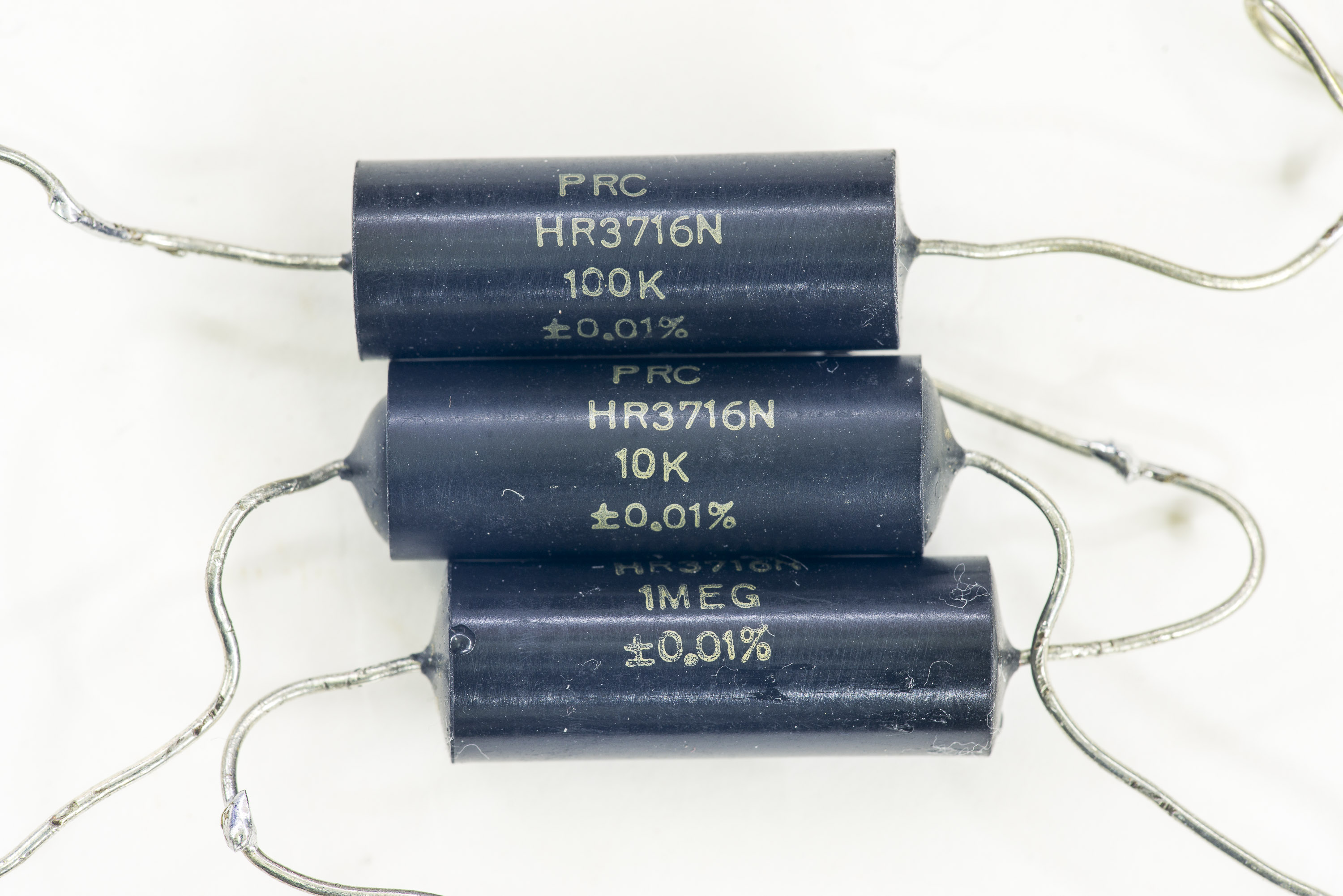
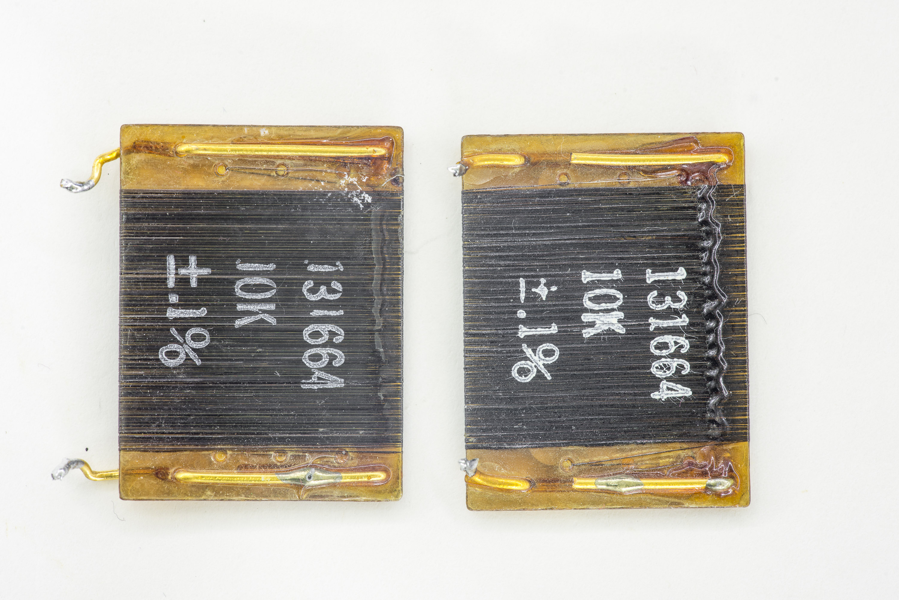
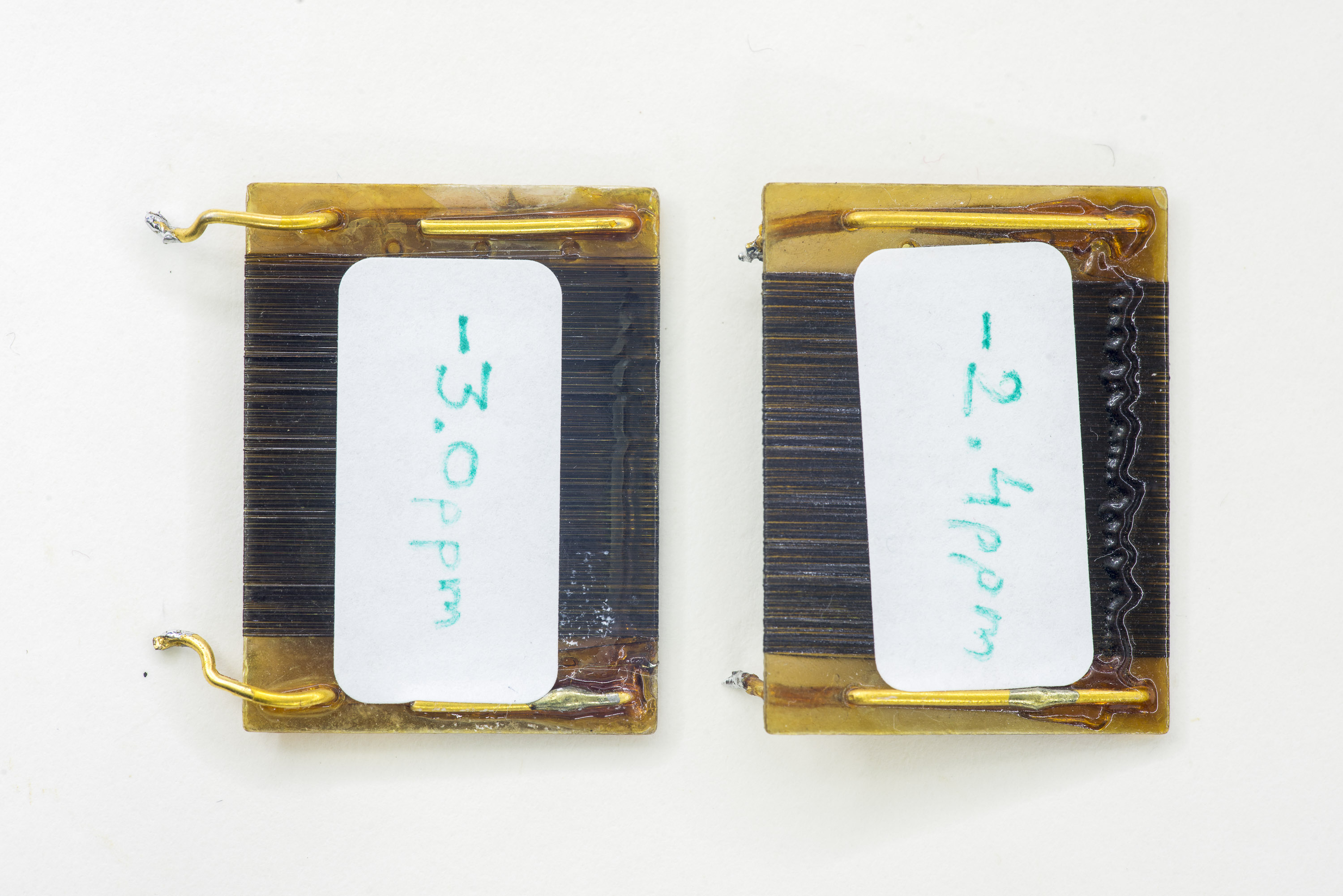
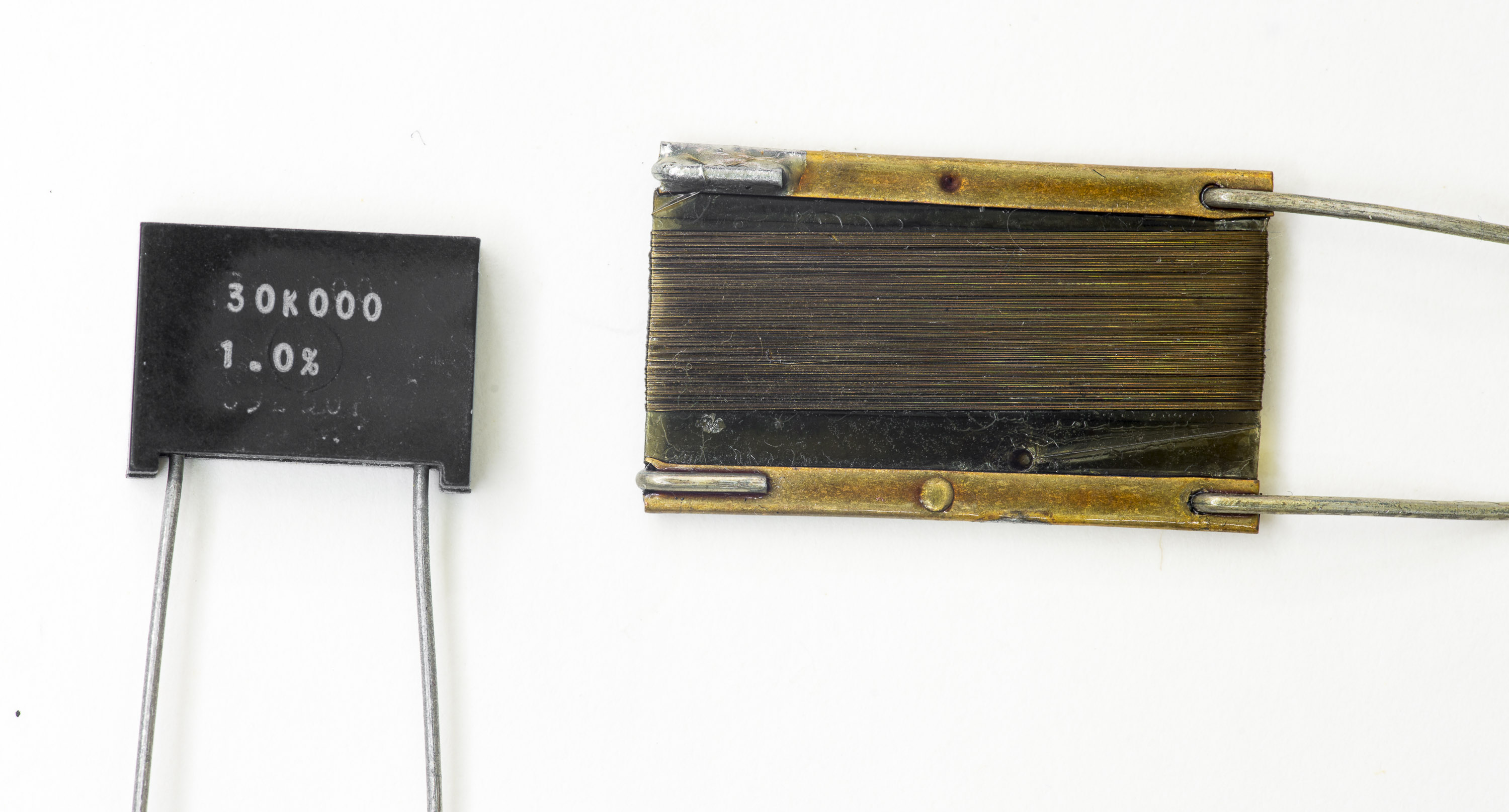
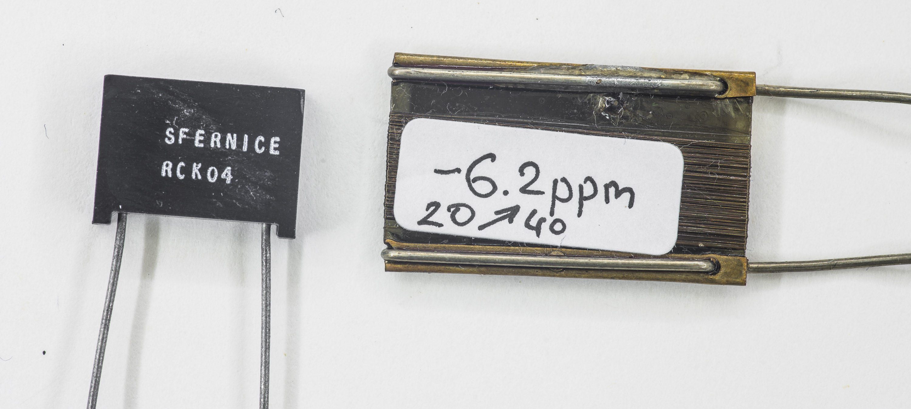
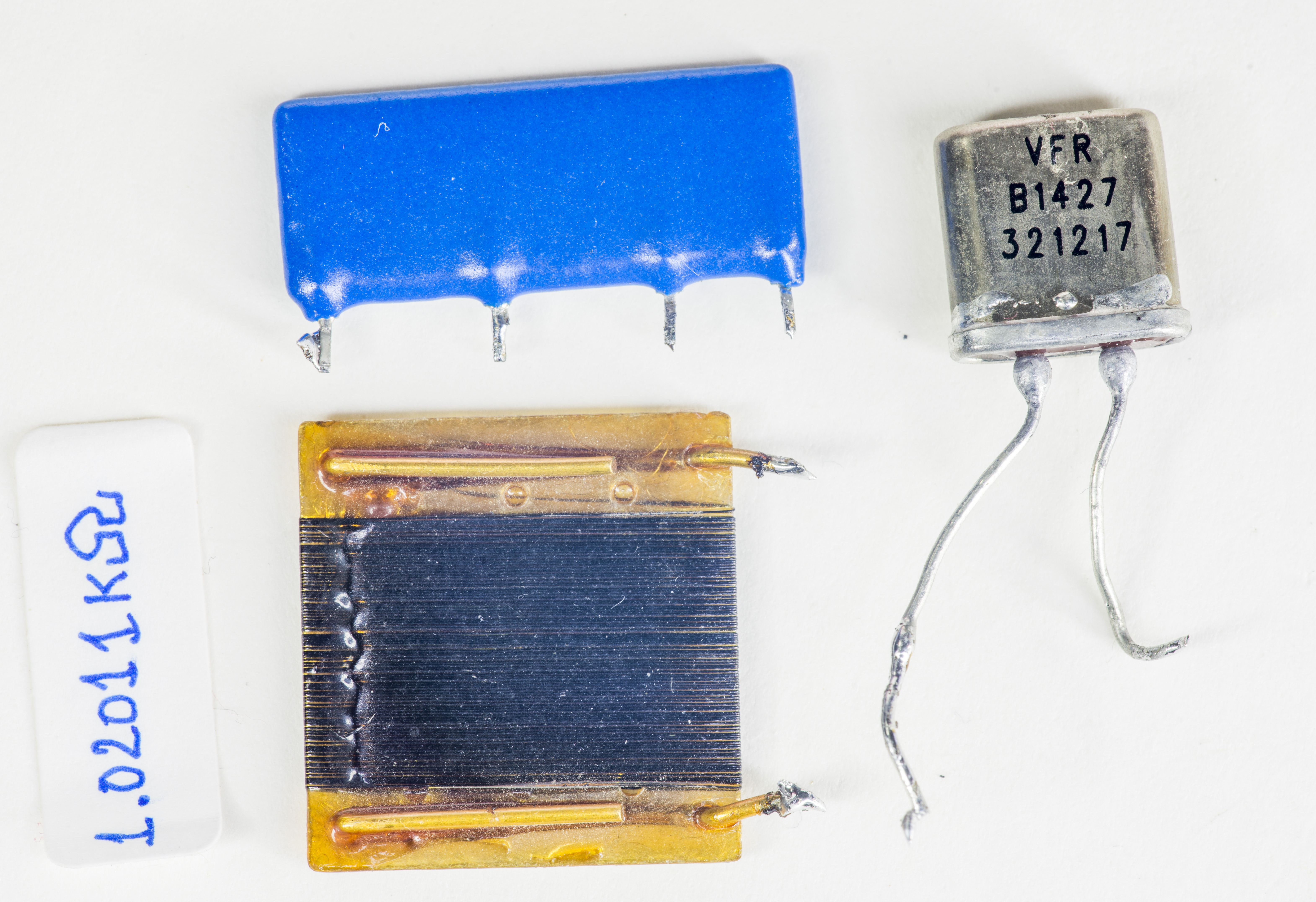
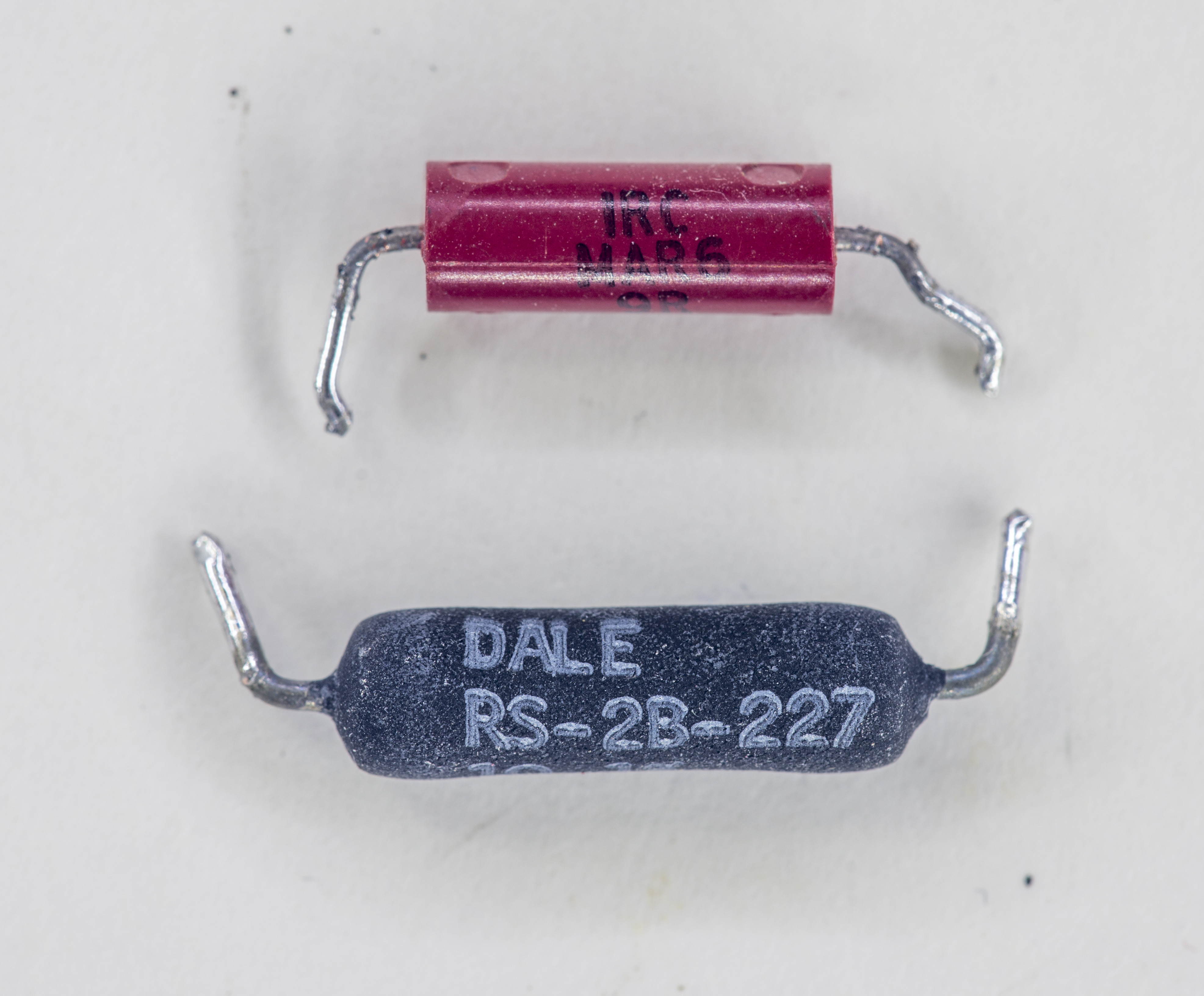
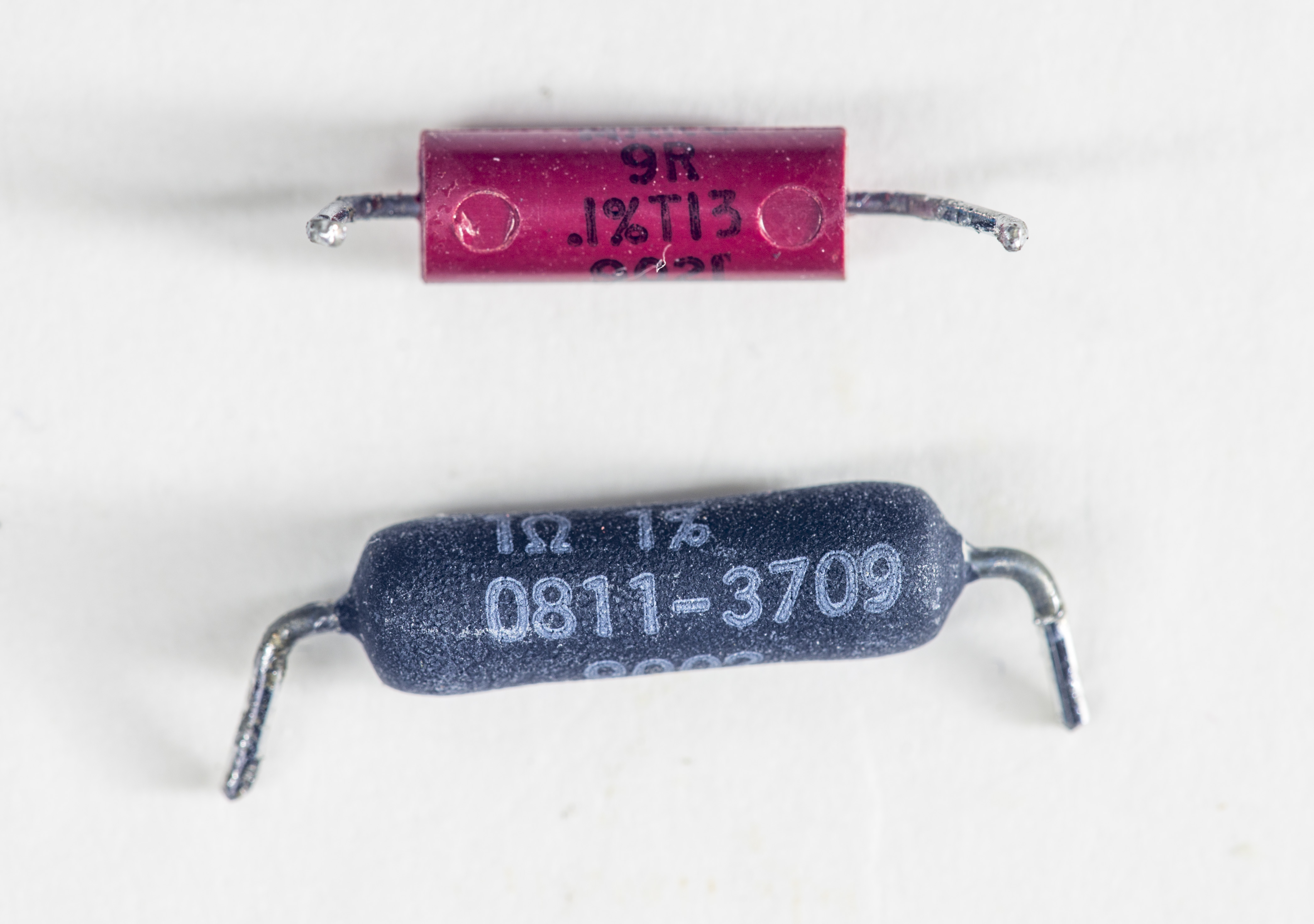
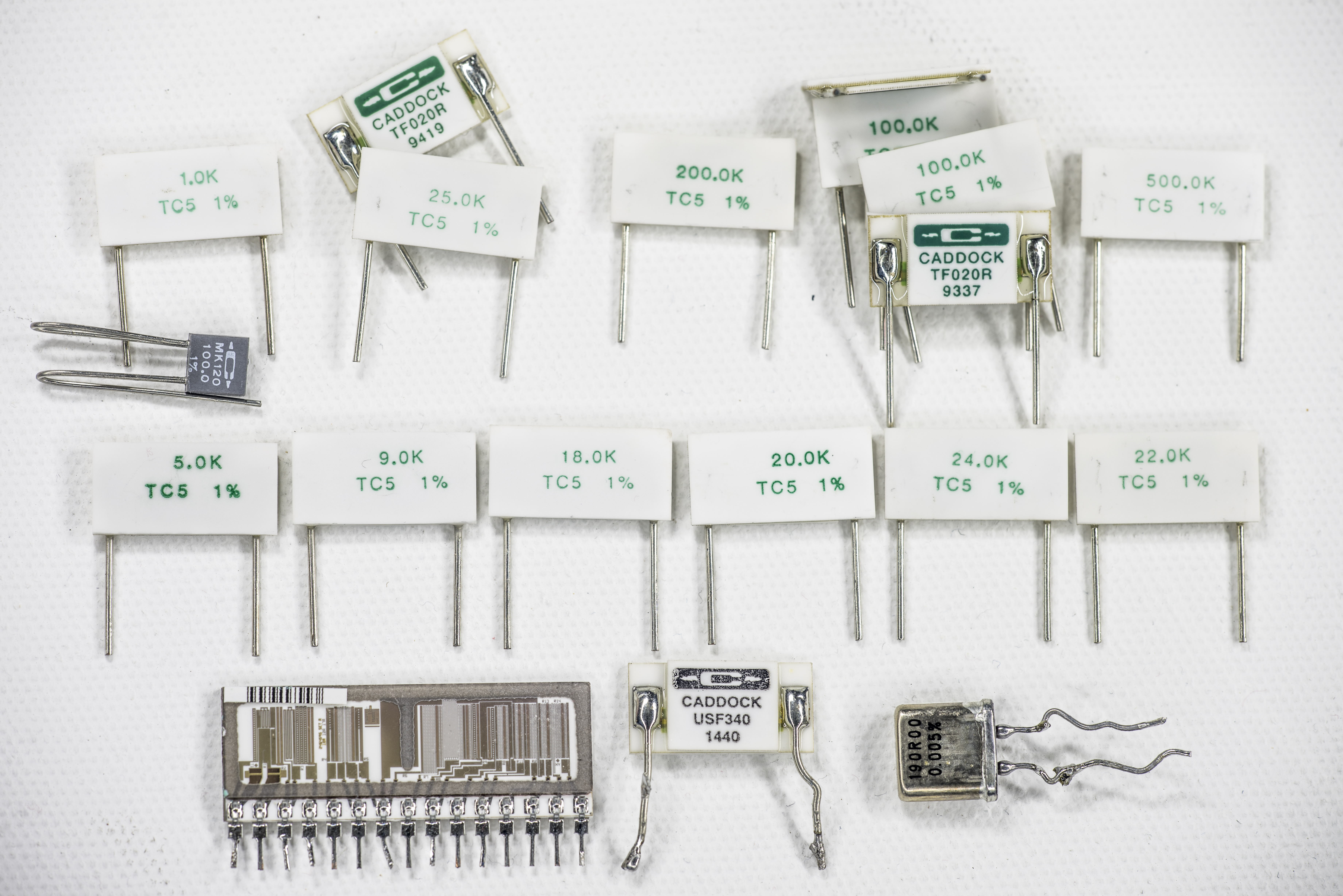
Image 1: Test resistors for tempco study
We will need stable resistance meter, temperature controller with little “oven” box and some Raspberry Pi software to automate the measurements. Often simple estimation of temperature coefficient can be made by measuring resistance on two points (low temperature, high temperature), but this may lead to inaccurate results due to non-linear resistance changes.
Test procedure and setup
So to do accurate temperature coefficient measurement slow temperature change speed over extended range is required. If resistor under test cooled or heated too fast thermal gradients may develop stress and cause larger resistance change compared to temperature coefficient change itself. Large wire-wound and large value resistors are especially sensitive in this respect. This speed is also sets overall temperature ramp test time, and can become multiple hours long. Test software app developed for this study tests each resistor for duration of 15-30 hours. Having 130 resistors to test that would mean three months of continuous testing, if we use just single ohm-meter.
To speed up testing multiple separate multimeters were used, with test resistors individually connected. Initial test runs were using three calibrated long-scale DMMs (HP 3458A, K2002-4 and K2002-6). Use of high performance DMM in stable environment is important, to ensure minimal error from meter drift/own tempco. Later test runs had forth calibrated HP 3458A added in the mix. Even better method would be using stable current source to drive test resistors and sensitive voltmeter. This setup will be used to measure tempco of low value resistors, such as 50 mΩ and 10 mΩ 4-terminal shunts. Lowest range of used DMMs (10 Ω in case of HP 3458A) lacks of required stability and too noisy for ppm-level temperature coefficients of such low resistances.
Alternative measurement can be also performed using resistance bridge with stable reference resistor held at constant temperature and DUT resistor in thermal chamber. However better in theory uncertainty comes at high price (require multiple standards), due to large magnitude of DUT resistance values, ranging from 0.1 Ω to 1 GΩ.
Thermal chamber
Each resistor under test was quickly (to reduce thermal stress of resistor element itself) soldered to twisted AWG34 test copper 4-wire cable. Other end is directly connected to DMM inputs in 4W configuration (except ranges >10MΩ, where 2 wires only are used). If resistor have four terminals, sense line connected separately to dedicated pins. Otherwise both sides tied as resistor sides.
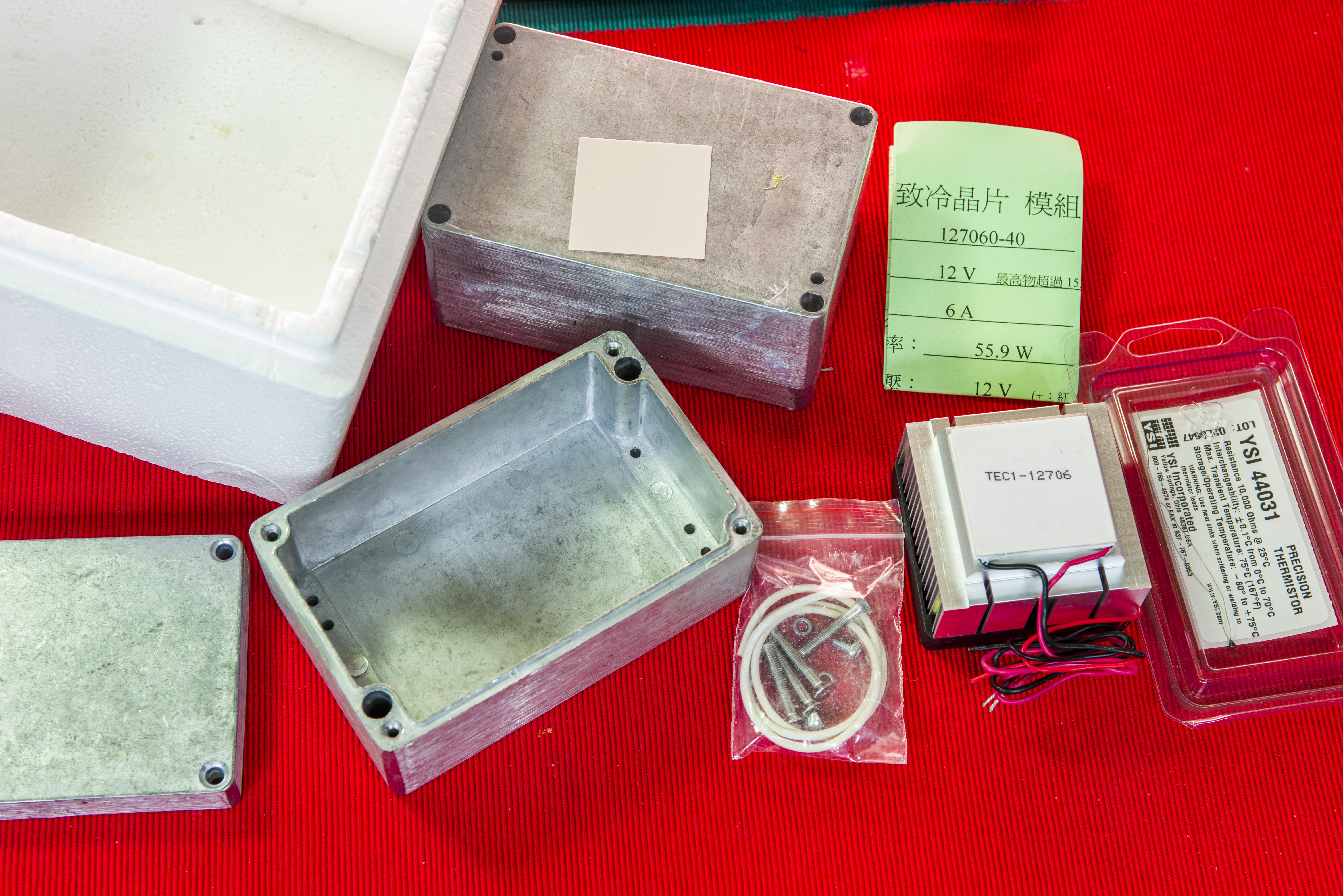
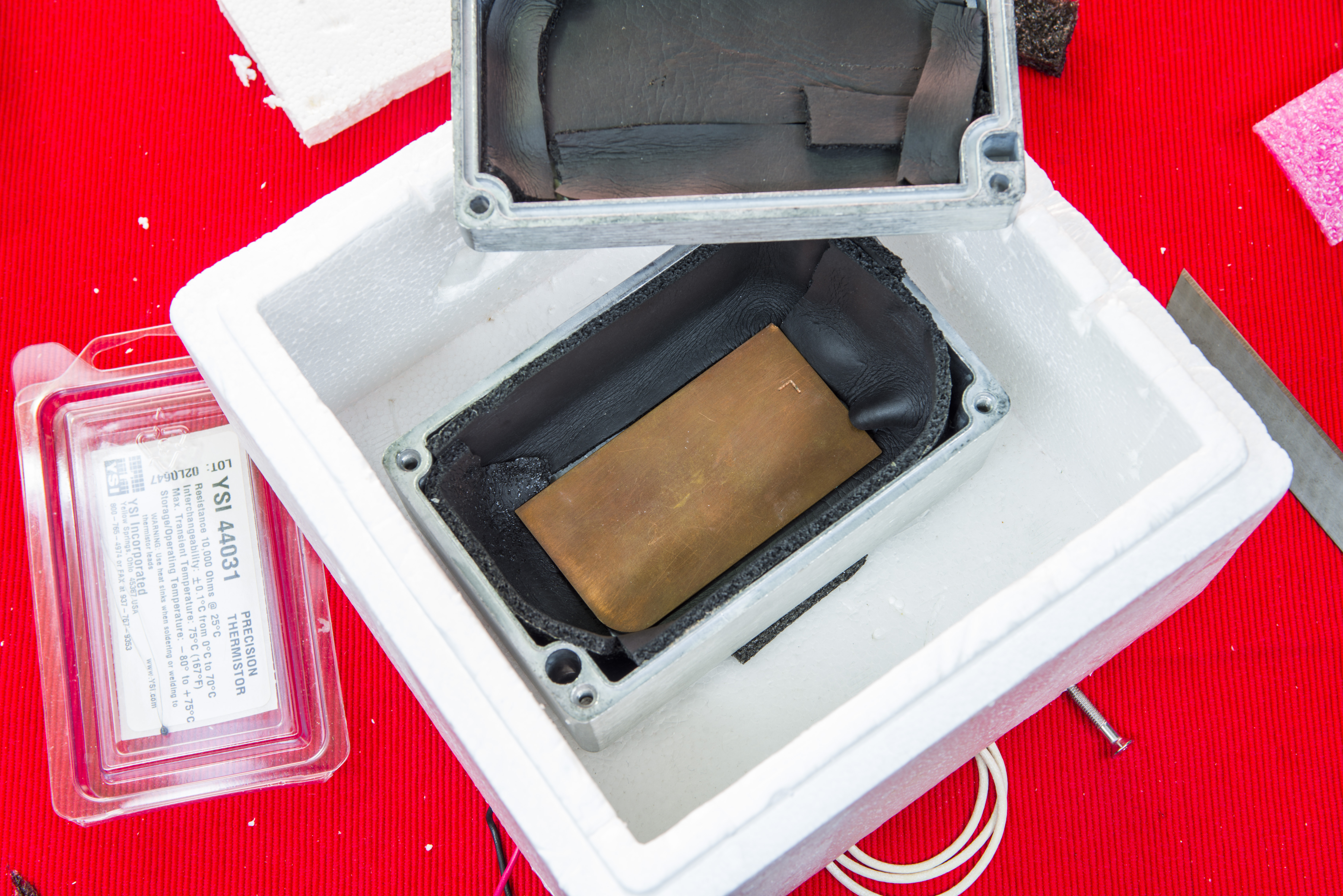
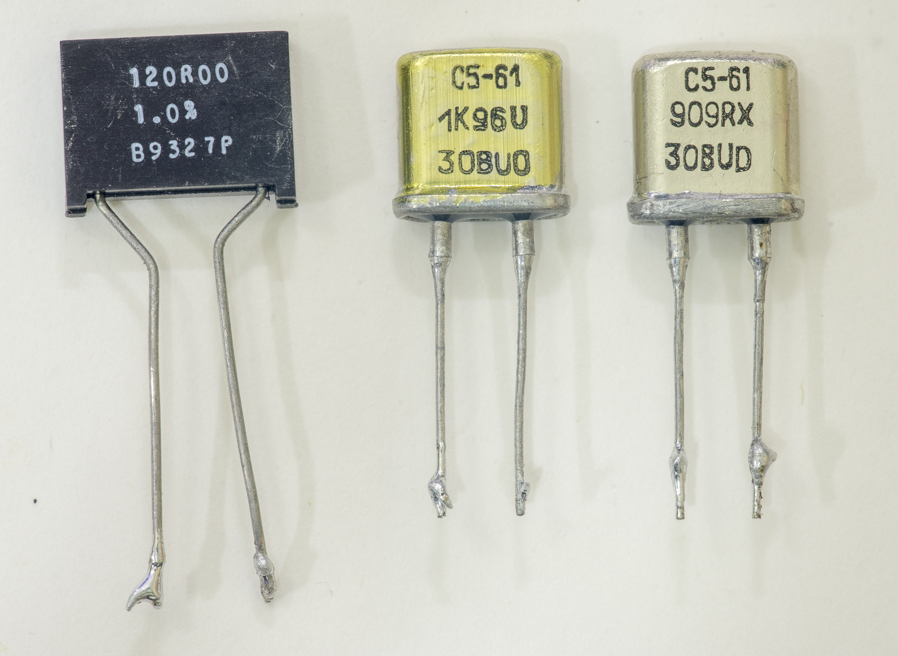
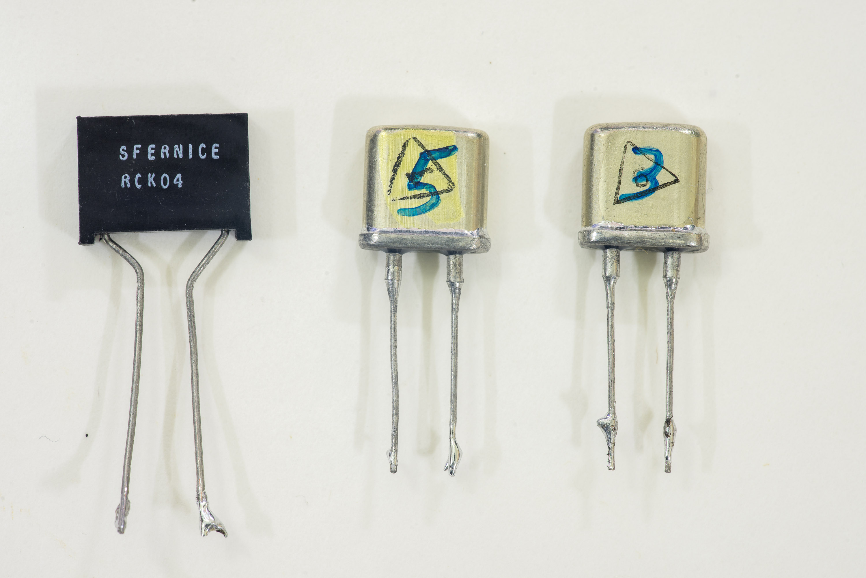
Image 2-3: Parts for DIY thermal box
Connected resistors are placed in metal die-cast box with copper slug and precision thermistor to monitor and feedback box inner temperature. Precision 10KΩ (25°C) thermistor from YSI, Model 44031 is used as thermal sensor feedback, connected to Keithley SMU by 4-wire cable. Today these termistors are manufactured and sold by Omega, another big and well-known thermal solutions manufacturer.
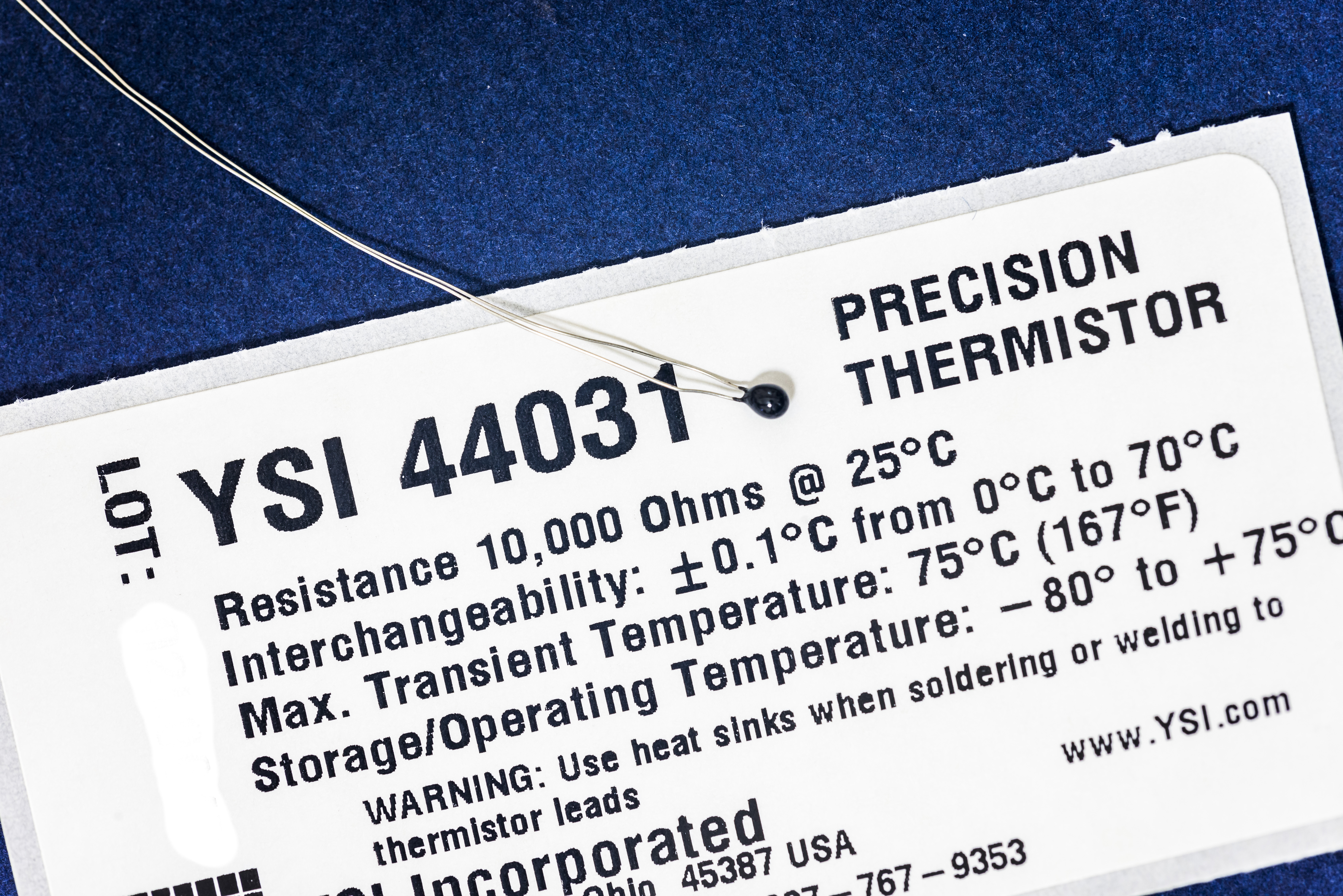
Image 4: Precision thermistor YSI 44031
Few mm thick copper plate added on the bottom of the chamber as thermal damper, with thermistor mounted in center. Thermal grease was used to enhance surface contact and provide good thermal coupling of sensor with metal slug to minimize self-heating and readings noise. Make sure you don’t subject sensitive thermistor to temperatures over +75°C and use heatsinking during leads soldering.
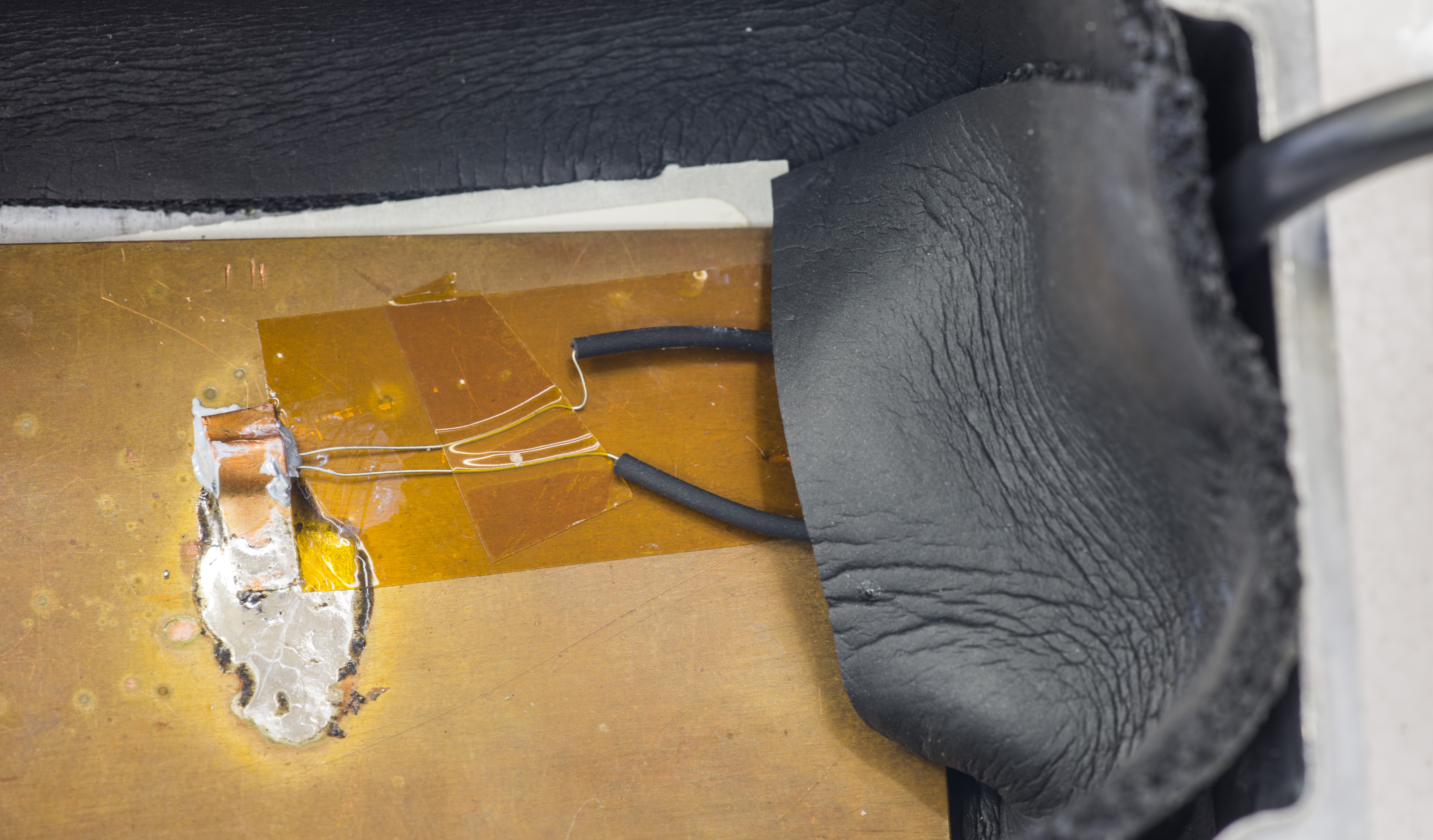
Image 5: Thermistor mounted to a plate
Box top cover is bolted down and whole test assembly placed in styrofoam larger container with 40W TEC and heatsink attached thru bottom. TEC setpoint, temperature control and power is maintained using Keithley 2510 TEC SMU.
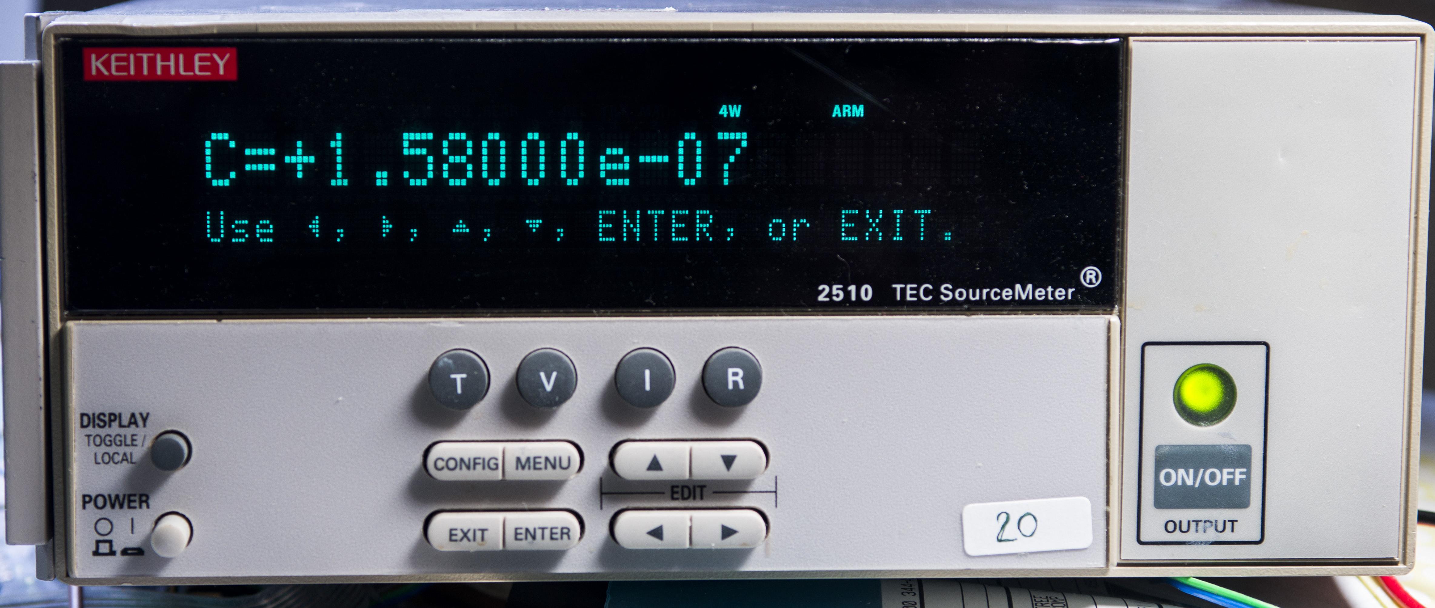
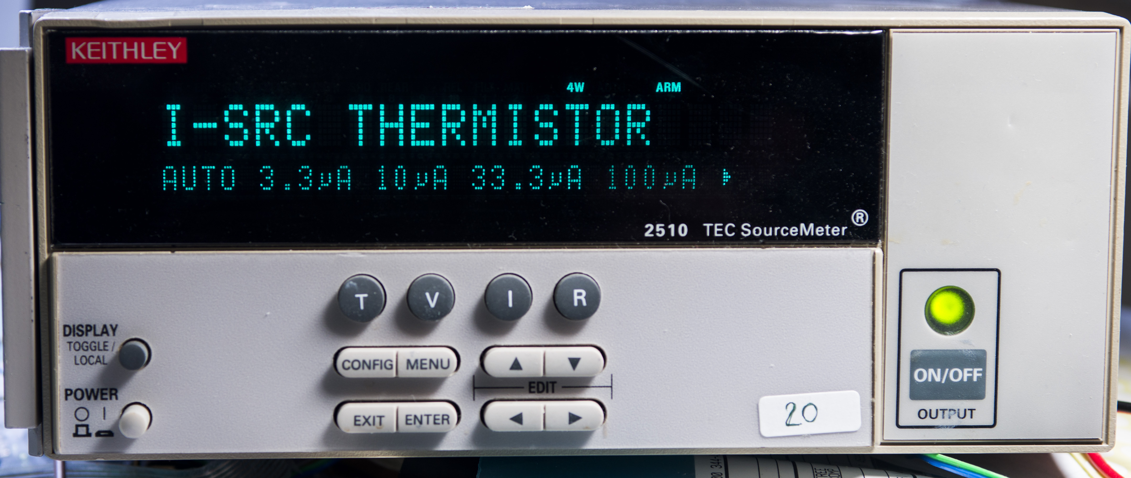
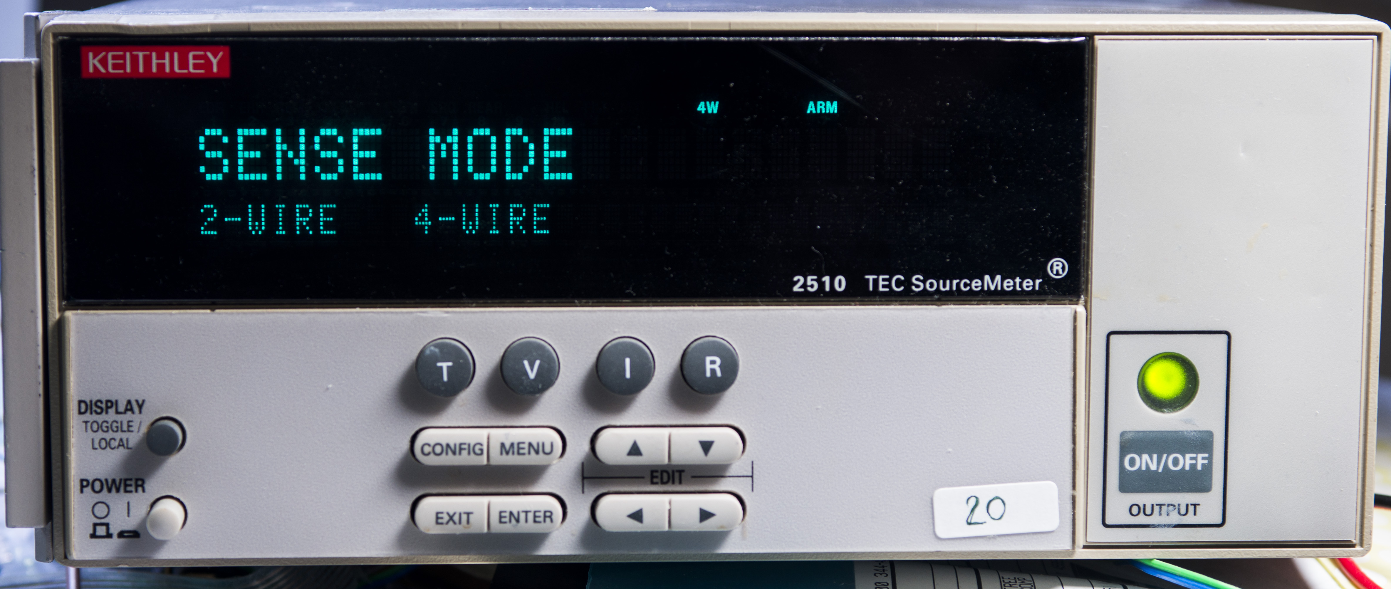
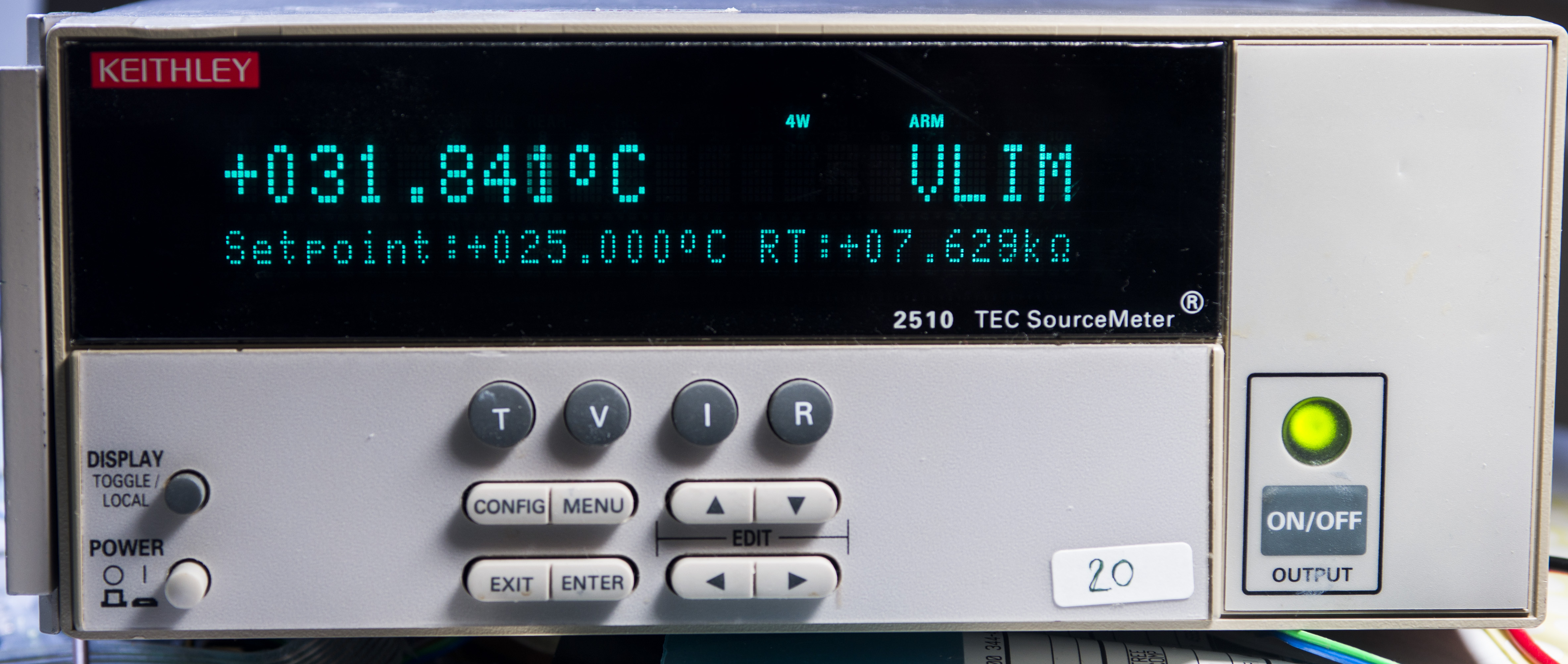
Image 6-9: Keithley 2510 configuration
Such simple yet effective setup allow to set and stabilize any temperature from +5°C to about +70°C with precision better than 0.05°C. Insulation required to reduce heat loss and influence of ambient temperature change on internal box temperature. This means that we will spend less power to adjust and maintain set temperature in the box.
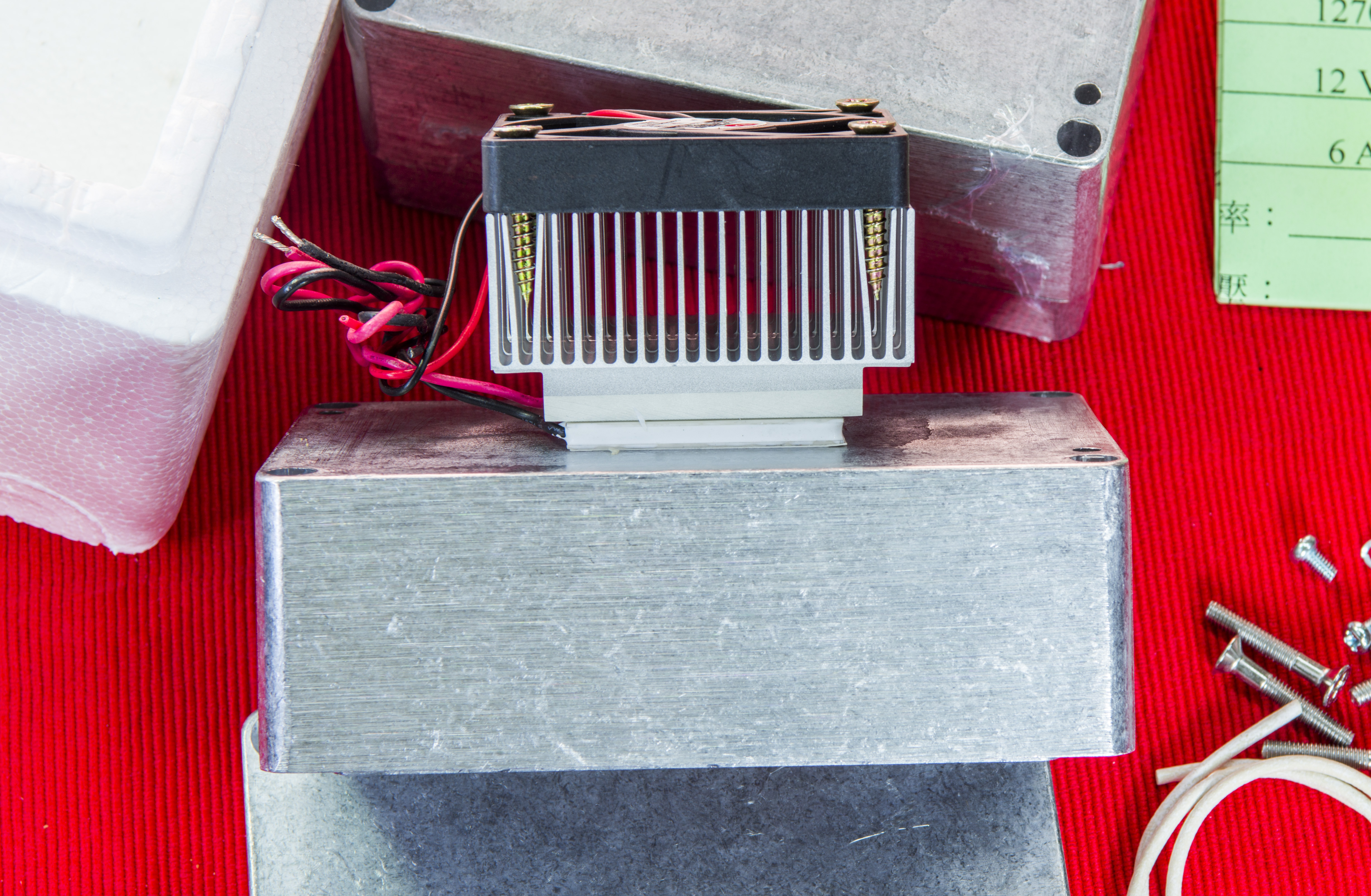
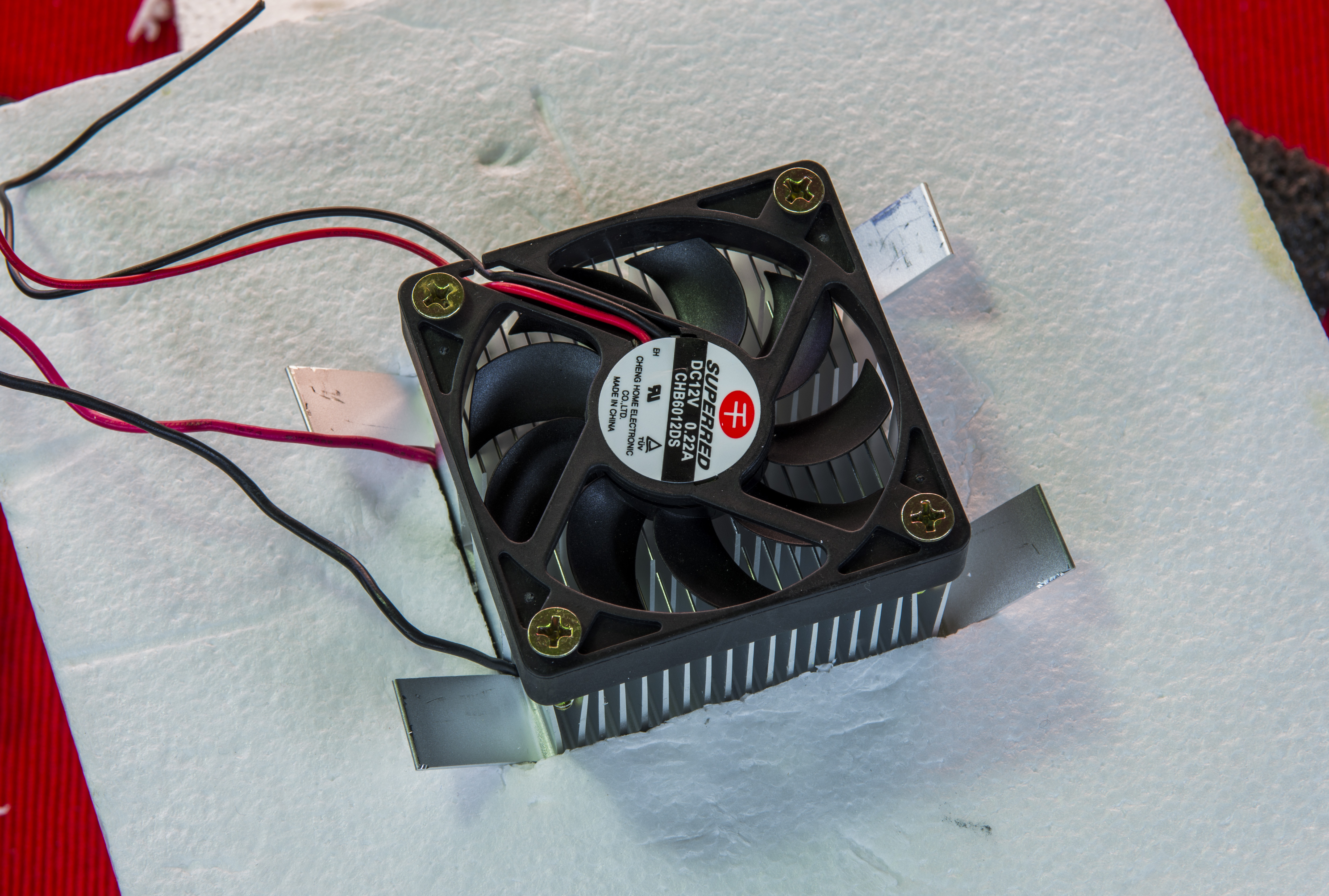
Image 10-11: Fansink and mount on the box
All instruments like DMMs and Keithley 2510 are remotely controlled by simple Python application, running on Terasic DE1-SoC board (or Raspberry Pi 3). Actual physical interface is GPIB, with linux-gpib as software framework. We have actual guides covering setup both popular NI GPIB-USB-HS and Agilent 82357B dongles with linux-gpib.
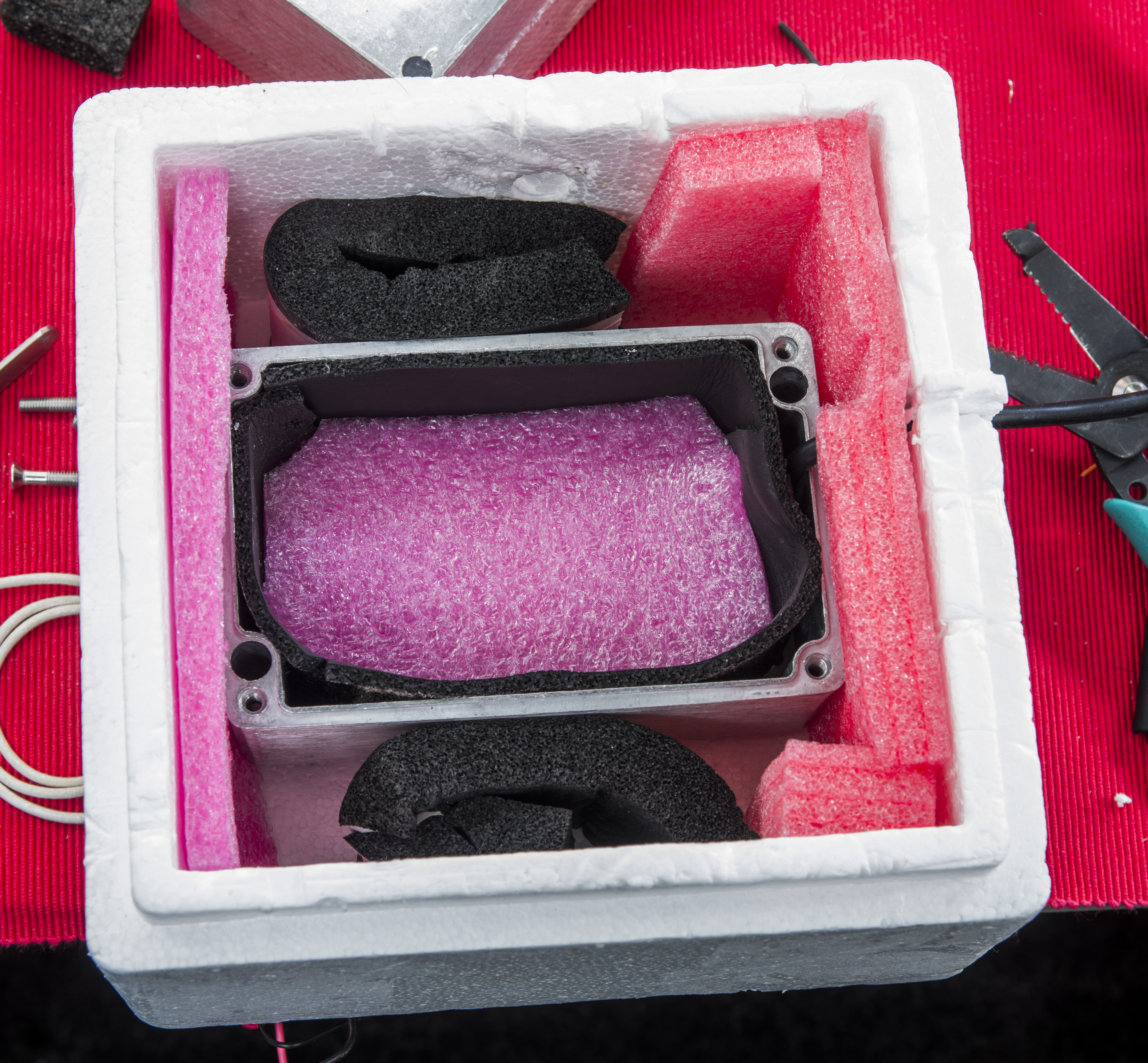
Image 12: Box ready for resistors test
Environment conditions such as ambient temperature, humidity and pressure are also logged at every sample, with help of Bosch BME280 I2C sensor. Here’s the guide setting it up with Python in linux.
Automated Python code
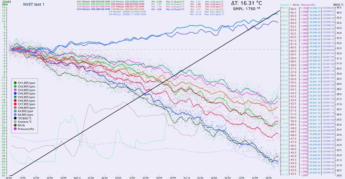
Actual test starts from configuring all meters to proper range, setting 3458A’s to NPLC 100 speed, AZERO on, OCOMP ON and Keithley 2002s to equivalent settings with NPLC 30. Meters then sampled in sequence, and box sensor temperature, TEC current are read from Keithley 2510. Each 20 samples (equals about 30 minutes of time) setpoint temperature increased by +0.1 °C. After reaching +40.0 °C ramp down sequence with same speed executed to bring box temperature down to +20 °C. This allow to also confirm symmetric temperature coefficient in both directions while heating or cooling resistor under test.
Python code used for TCR measurement with 2×3458A,2xKI2002,2510 and BME280
Few key code blocks to configure:
root_dir = '/repo/3458/'
fileName4 = root_dir + 'vpg20_tcr1_nplc100_tin.csv'
Variable fileName4 stores target result data filename, to be stored in root_dir folder.
Keithley 2510 is a TEC SMU, configured to YSI thermistor and used chinese cheap TEC element 127060-040, rated for 12Vmax at 6 A.
def init_inst(self):
        # Setup SCPI TEC SMU
	#Set temperature transducer to thermistor and 4-wire sense mode
	self.inst.write(":sens:temp:tran ther")       #select thermistor as sensor
	self.inst.write(":sens:temp:ther:a 1.032e-3") #Thermistor A
	self.inst.write(":sens:temp:ther:b 2.387e-4") #Thermistor B
	self.inst.write(":sens:temp:ther:c 1.580e-7") #Thermistor C
	self.inst.write(":sens:temp:ther:rang 10000") #10 kOhm thermistor
	self.inst.write(":sens:temp:curr 1e-4")       #Test current 100uA for thermistor
	self.inst.write(":syst:rsen on")              #4-wire mode enabled
	self.inst.write(":sour:volt:prot 10.0")       #10V limit
	#Set current limit
	self.inst.write(":sens:curr:prot 3.0")        # 3A limit
	#Set temperature limit*
	self.inst.write(":sour:temp:prot:high 65")    # 65C max temp
	self.inst.write(":sour:temp:prot:low 5")      # 5C min temp
	self.inst.write(":sour:temp:lcon 70")         # P = 70
	self.inst.write(":sour:temp:lcon:int 0.03")   # I = 0.03
	self.inst.write(":sour:temp:lcon:der 1.8")    # D = 1.8
	self.inst.write(":sour:temp:prot:state ON")   #enable temp protection (default)
Coefficients A,B,C are taken from actual sensor datasheet, and PID values are tweaked to work on my specific thermal box setup, shown above in this article. Let’s take a look on Keithley 2002’s config:
def init_inst_fres(self):
        # Setup SCPI DMM
        self.inst.clear()
	self.inst.write("*RST")
	self.inst.write("*CLR")
        self.inst.write(":SYST:AZER:TYPE SYNC")
        self.inst.write(":SYST:LSYN:STAT ON")
	self.inst.write(":SENS:FUNC 'FRES'")           # Select 4-wire resistance
	self.inst.write(":SENS:FRES:DIG 9;NPLC 30;AVER:COUN 10;TCON MOV") # Set 8.5-digit mode, NPLC 30
	self.inst.write(":SENS:FRES:AVER:STAT OFF")    # No filtering
	self.inst.write(":SENS:FRES:OCOM ON")          # Offset compensation on (used up to 20Kohm)
	self.inst.write(":SENS:FRES:RANG 2E3")         # Range 2 Kohm
        self.inst.write(":FORM:ELEM READ")
Similar configuration also used for Keysight 3458A multimeters
def init_inst(self):
        # Setup HP 3458A
        self.inst.clear()
        self.inst.write("PRESET NORM")
        self.inst.write("OFORMAT ASCII")
        self.inst.write("OHMF 10E6")
        self.inst.write("TARM HOLD")
        self.inst.write("TRIG AUTO")
        self.inst.write("NPLC 100")
        self.inst.write("AZERO ON")
	self.inst.write("OCOMP ON")
        self.inst.write("LFILTER ON")
        self.inst.write("NRDGS 1,AUTO")
        self.inst.write("MEM OFF")
        self.inst.write("END ALWAYS")
        self.inst.write("NDIG 9")
	self.inst.write("DELAY 1")     # second delay to mitigate OCOMP accuracy issue due DA on 1k-100k ranges
And finally code logic that runs temperature ramps:
while cnt <= 400000:
    cnt+=1

    if ( (cnt >= 100) and (enable_start == 0) ):
	enable_start = 1
        cnt = 0

    if (enable_start == 1):
        if (xtemp >= 40.0 and reverse_dir == 0):
    	    reverse_dir = 1
    	    cnt = 0

        if ( ((cnt % 10) == 0) and (reverse_dir == 0) ):
	    xtemp = 20 + ((float(cnt) / 10)*0.1)
	    print ("Set TEC Temp = %2.1f" % xtemp)
	    meter2510.deduct_tmp(xtemp)

    if ( (cnt >= 50) and (reverse_dir == 1) ):
	enable_hold = 1
	cnt = 0

    if ( ((cnt % 10) == 0) and (reverse_dir == 1) and (reverse_dir == 1) ):
        xtemp = 40 - ((float(cnt) / 10)*0.1)
        print ("Set TEC Temp = %2.1f" % xtemp)
        meter2510.deduct_tmp(xtemp)

    if (xtemp <= 19.9 and reverse_dir == 1):
	quit()
This code uses counter for timespan, with data collected from meters on each count, and temperature configured on each 10th count. First 100 counts code runs with fixed 20 °C setpoint, to obtain our reference point readings, used as 0.0 ppm calculation reference. This is our start. Next step is to increase temperature setting at +0.1 °C increments by programming Keithley 2510 SMU.
Once temperature reaches +40.0 °C code will keep this temperature level for another 50 samples, to ensure resistors under test are stable. Next is ramp down in -0.1 °C change till reach of final value +20.0 °C. Ramp down data used on some resistors tests, to confirm accurate and uniform results, so it’s not used on every case.
Interesting results
Test results
Initial TCR test based on few 2C/3C spots, in step programming:
| Resistor | Meter | Result |
|---|---|---|
| 1K | 3458A | +1.25 ppm/K |
| 10K | 2002-4 | +6.67 ppm/K |
| 100K | 2002-6 | +1.5 ppm/K |

10KΩ is bad, surely. So I’d think it’s one off, rather than PRC issue. 1K and 100K well below spec.
PRC 1Meg at one of 2002’s and fluke wirewound mica 10K (one at another 2002, second at 3458)
So far PRC 1Meg is nice, +0.8ppm, down in the noise, from 20C to 30C, and even less from 30C to 38C
Fluke WW 10K 2002: -3.05ppm/K
Fluke WW 10K 3458: -2.4ppm/K

TC 3458 (AE 9R000) : +1.5…+0.94 ppm/K
TC 2002-4 (S102 634R00) : -1.2…1.25 ppm/K
TC 2002-6 (S102 634R00) : -1.3…-1.56 ppm/K
Datalog – tweaked snake so it ramps 0.1c/4 minutes to give smooth nice ramp.
TC 3458 (VPG S102 120R00) : -0.65 ppm/K
TC 2002-4 (soviet BMF S5-61 908R84) : -2.78 ppm/K
TC 2002-6 (soviet BMF S5-61 1.96K00) : +3.95 ppm/K
Datalog – more tests
TC 3458 (VPG CSNG 2.5R #2) : -0.3 ppm/K
TC 2002-4 (SFERNICE 30K) : +0.15 ppm/K
TC 2002-6 (Wirewound 30K) : -6.2 ppm/K
SFERNICE 30K surprised me, almost zero TCR, yay. CSNG is rocking too.


TC 3458 (VPG VPR5 1.0R #1) : +16.5 ppm/K
TC 2002-4 (Soviet WW 100ohm big bobin) : -11 ppm/K
TC 2002-6 (Soviet S5-5-5W 9.1k 0.05%) : -25 ppm/K

TC 3458 (VPG 0.1R CSNG #1) : +0.55 ppm/K
TC 2002-4 (HP 3458A HV-divider 100K) : +3.2 ppm/K
TC 2002-4 (HP 3458A HV-divider 10M) : +2.9 ppm/K
TC 3458 (VPG 2.5R CSNG #1) : -0.175 ppm/K
TC 2002-6 (Fluke WW 1.02K) : -3.05 ppm/K
TC 2002-6 (VPG magical VHP101 19K 0.005% with PMO and matching) : -0.105 ppm/K
Resistance value calculator
Results from direct measurements
Each resistor test result can be viewed by clicking on ppm/K value link, which leads to separate page with graph and DSV-datalog file. Photo of each specimen also presented for overview.
| Resistor | Value | Meter | Result | Sample photo |
|---|---|---|---|---|
| Soviet S5-5-5W 0.05% | 9.1 KΩ | 2002-6 | -25 ppm/K | 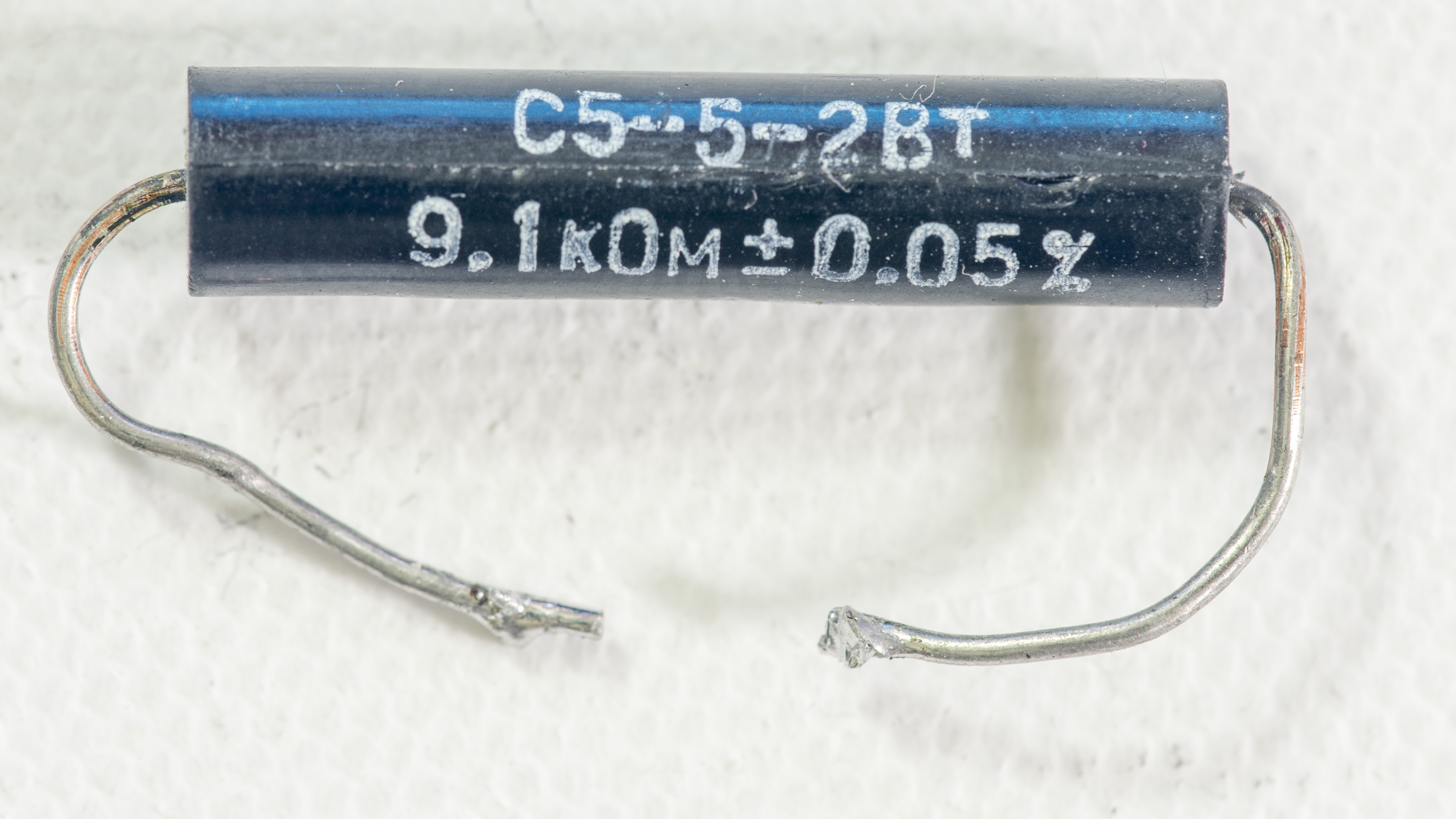 |
| VWW Wirewound 0.5% | 20 KΩ | 2002-6 | -6.2…-13 ppm/K | 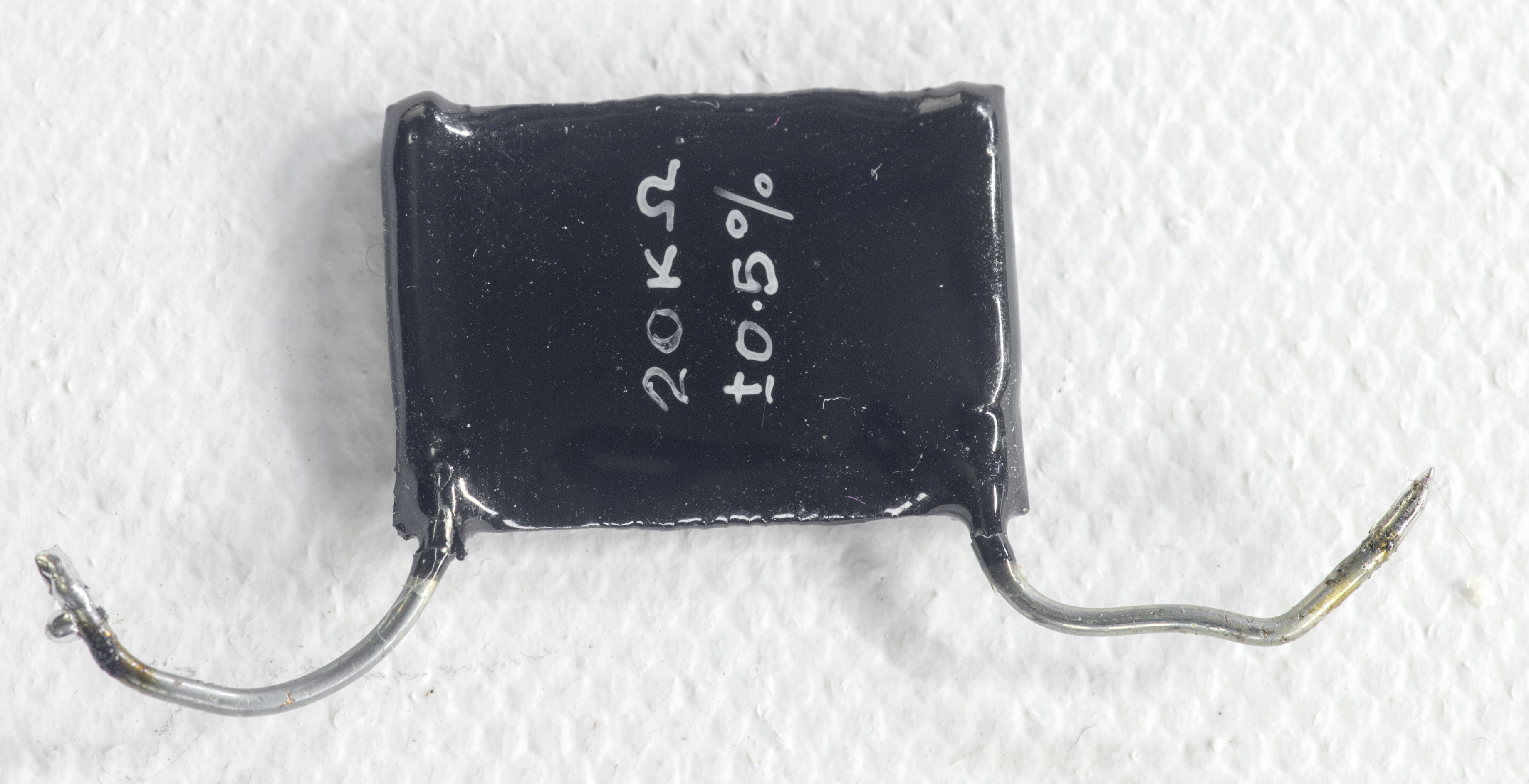 |
| Soviet WW big bobin | 100 Ω | 2002-4 | -11 ppm/K | 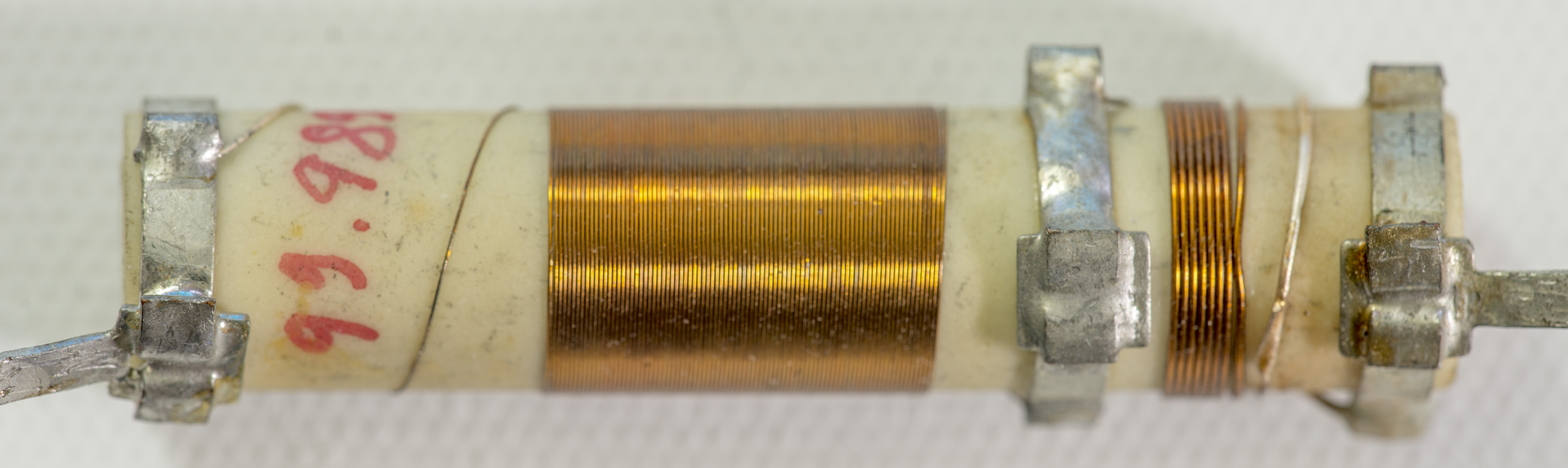 |
| Fluke WW 201699 from 720A, | 5.915 Ω | 2002-4 | -8.5 ppm/K |  |
| PTF56 15ppm spec, #1 | 75 KΩ | 2002-6 | -7.06 ppm/K | 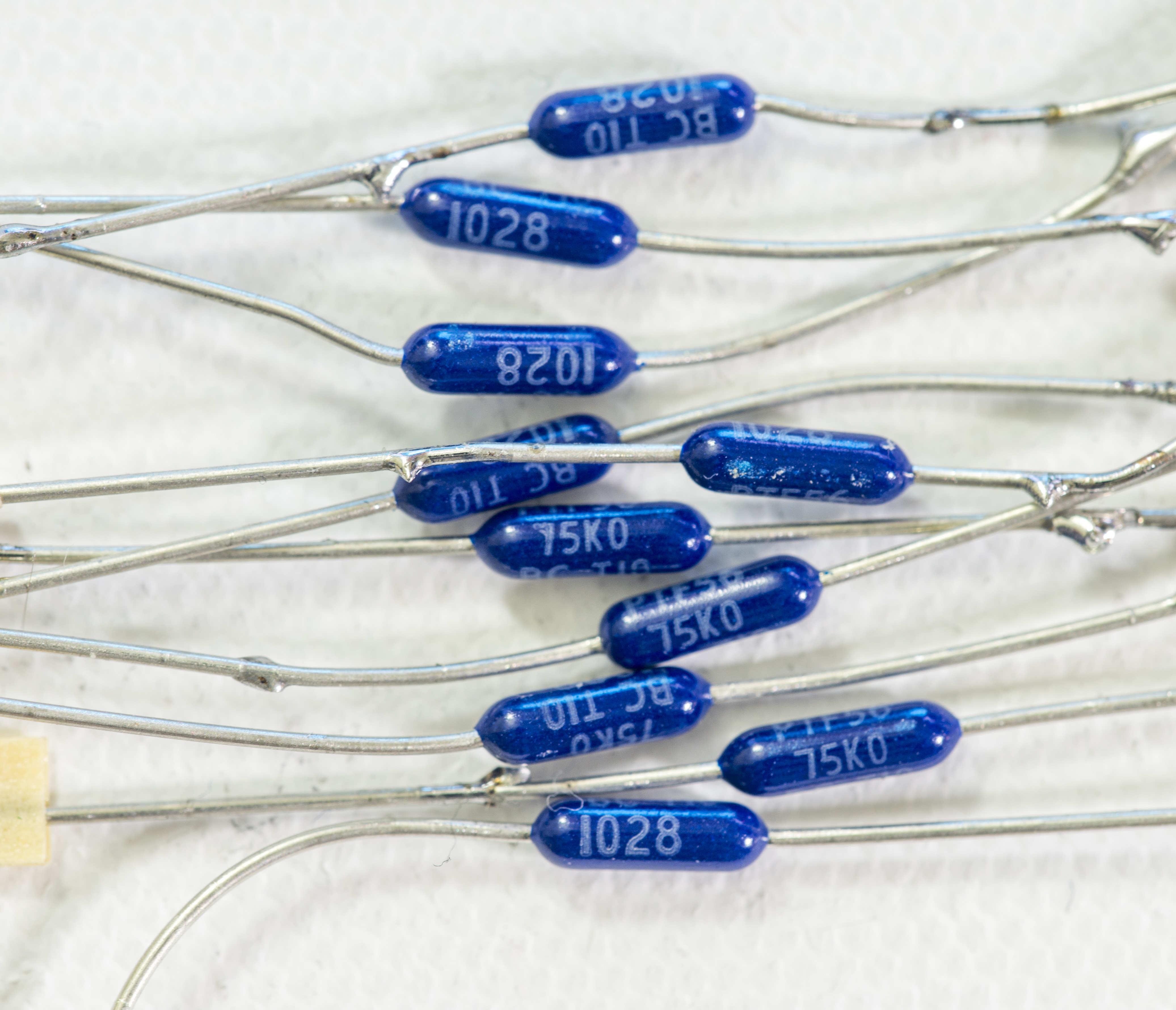 |
| PTF56 15ppm spec, #2 | 75 KΩ | 3458A | -7 ppm/K | |
| Wirewound long | 120 Ω | 2002-6 | -6.75 ppm/K | 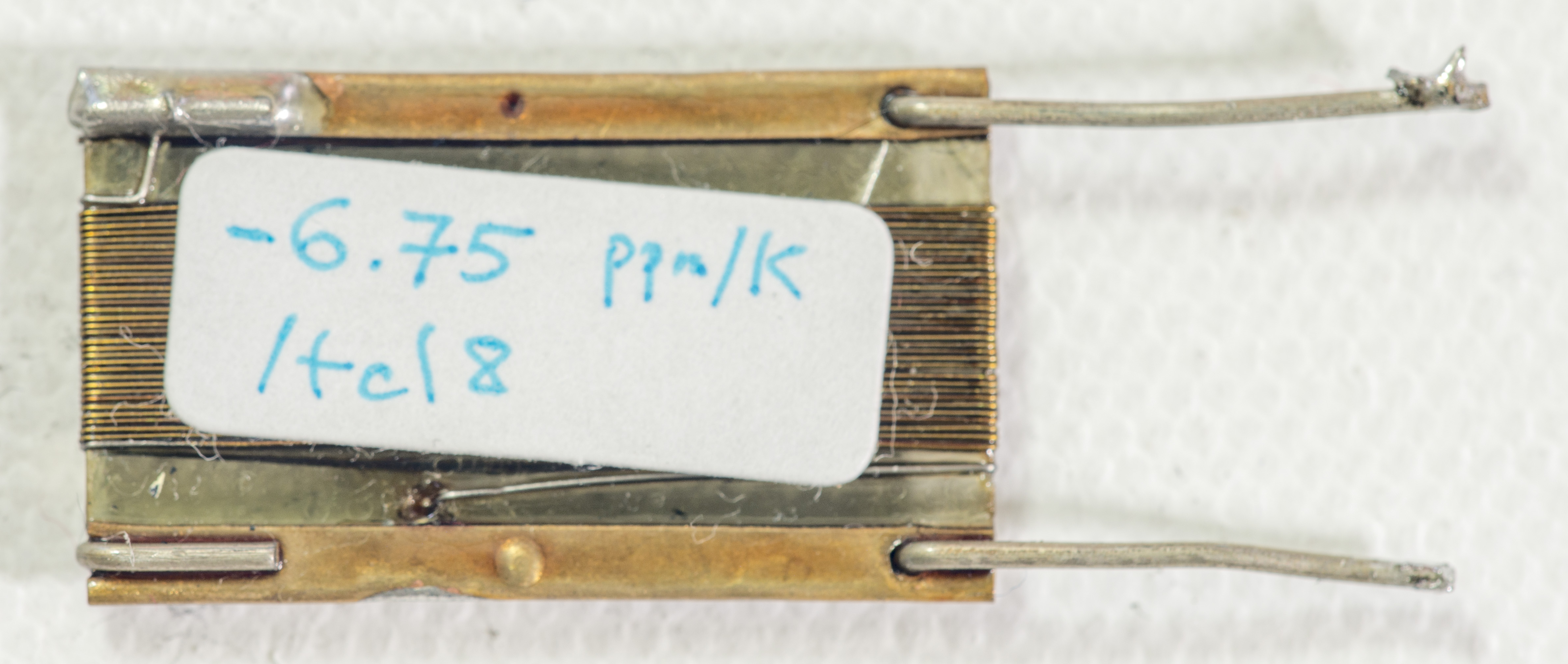 |
| PTF56 15ppm spec, #4 | 75 KΩ | 2002-4 | -6.3 ppm/K | |
| Wirewound | 30K Ω | 2002-6 | -6.2 ppm/K | 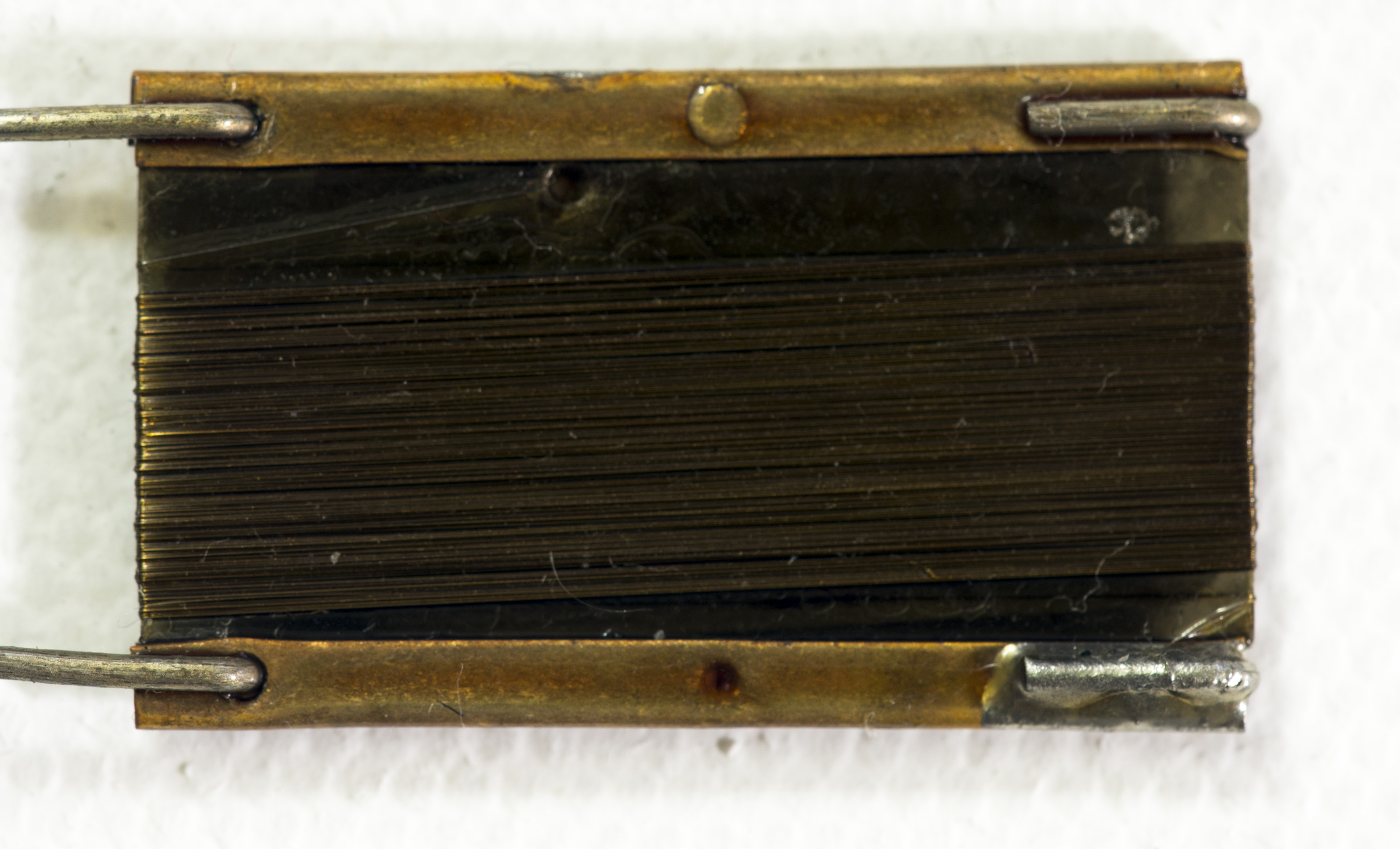 |
| PTF56 15ppm spec, #6 | 75 KΩ | 3458A | -5.9 ppm/K | |
| PTF56 15ppm spec, #10 | 75 KΩ | 2002-4 | -5.0 ppm/K | |
| PTF56 15ppm spec, #7 | 75 KΩ | 3458B | -3.8 ppm/K | |
| Soviet S5-61 10ppm spec | 1.01 KΩ | 2002-4 | -3.8 ppm/K | 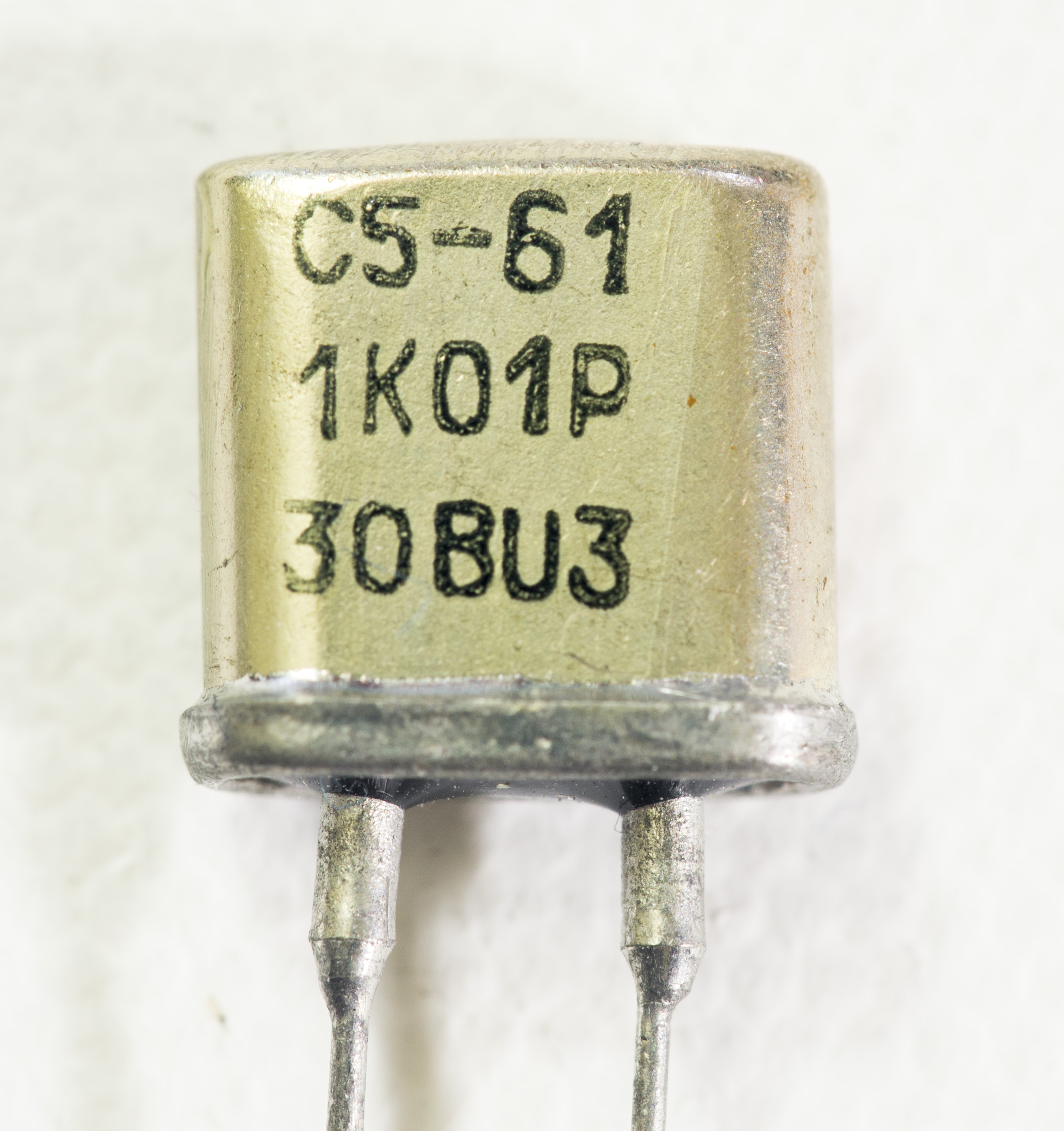 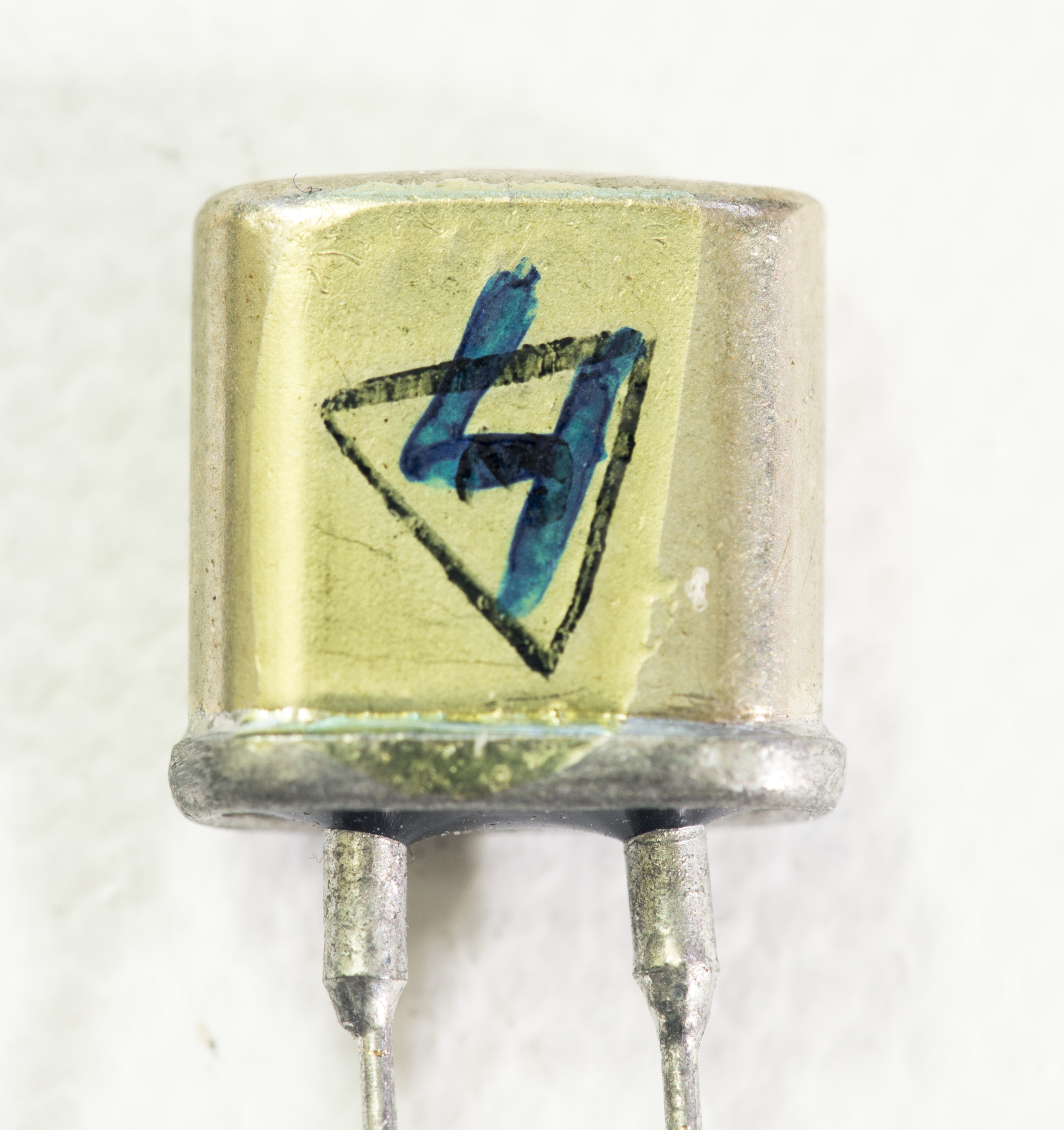 |
| S5-61 11.1K 10ppm spec | 11.1 KΩ | 2002-6 | -3.65 ppm/K | |
| PTF56 15ppm spec, #3 | 75 KΩ | 3458B | -3.4 ppm/K | |
| Fluke WW | 10 KΩ | 2002-6 | -3.05 ppm/K | 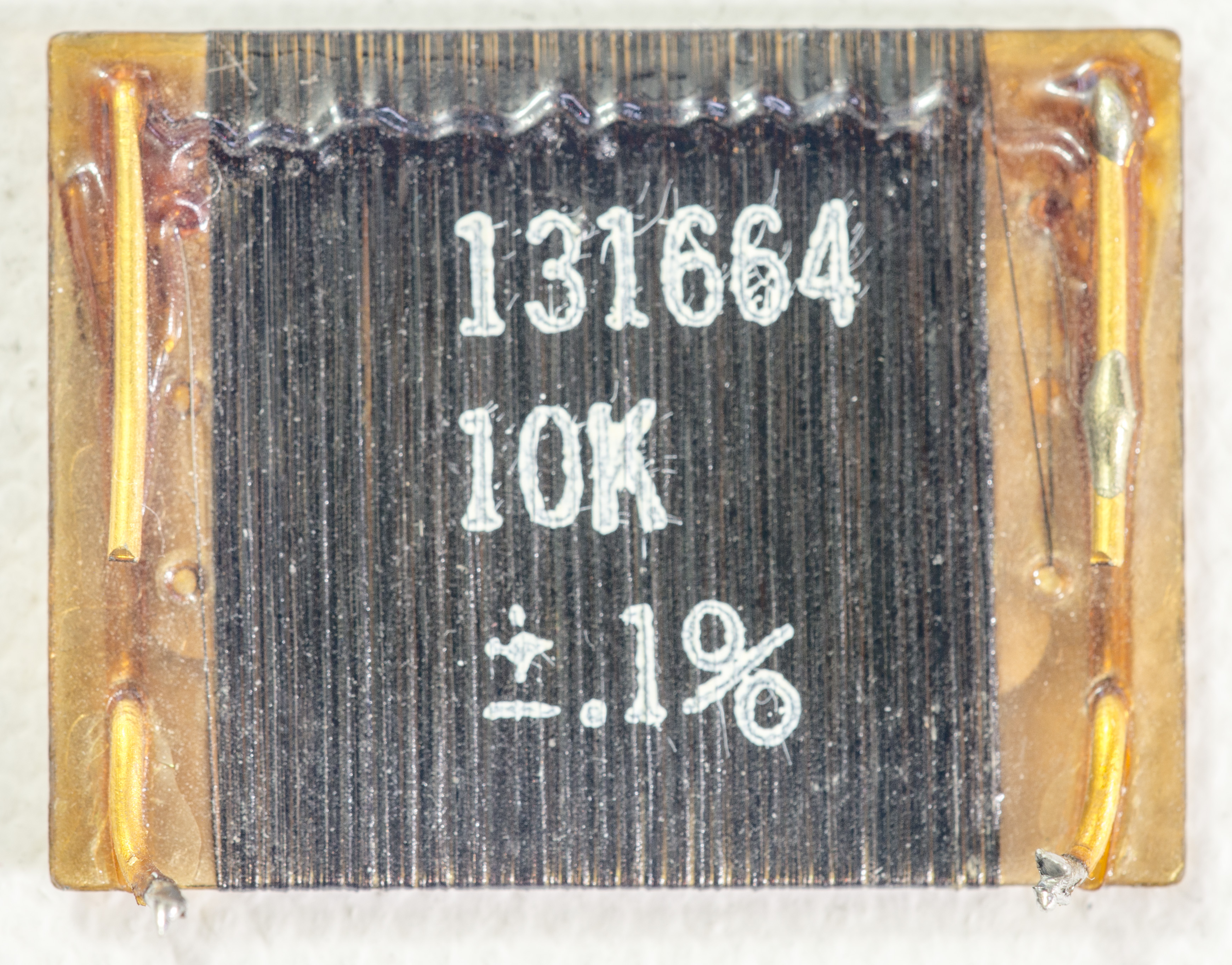 |
| Fluke WW | 1.02 KΩ | 2002-6 | -3.05 ppm/K |  |
| soviet BMF S5-61 | 908.84 Ω | 2002-4 | -2.78 ppm/K | |
| PTF56 15ppm spec, #8 | 75 KΩ | 2002-4 | -2.6 ppm/K | |
| Fluke WW | 10 KΩ | 3458A | -2.4 ppm/K | 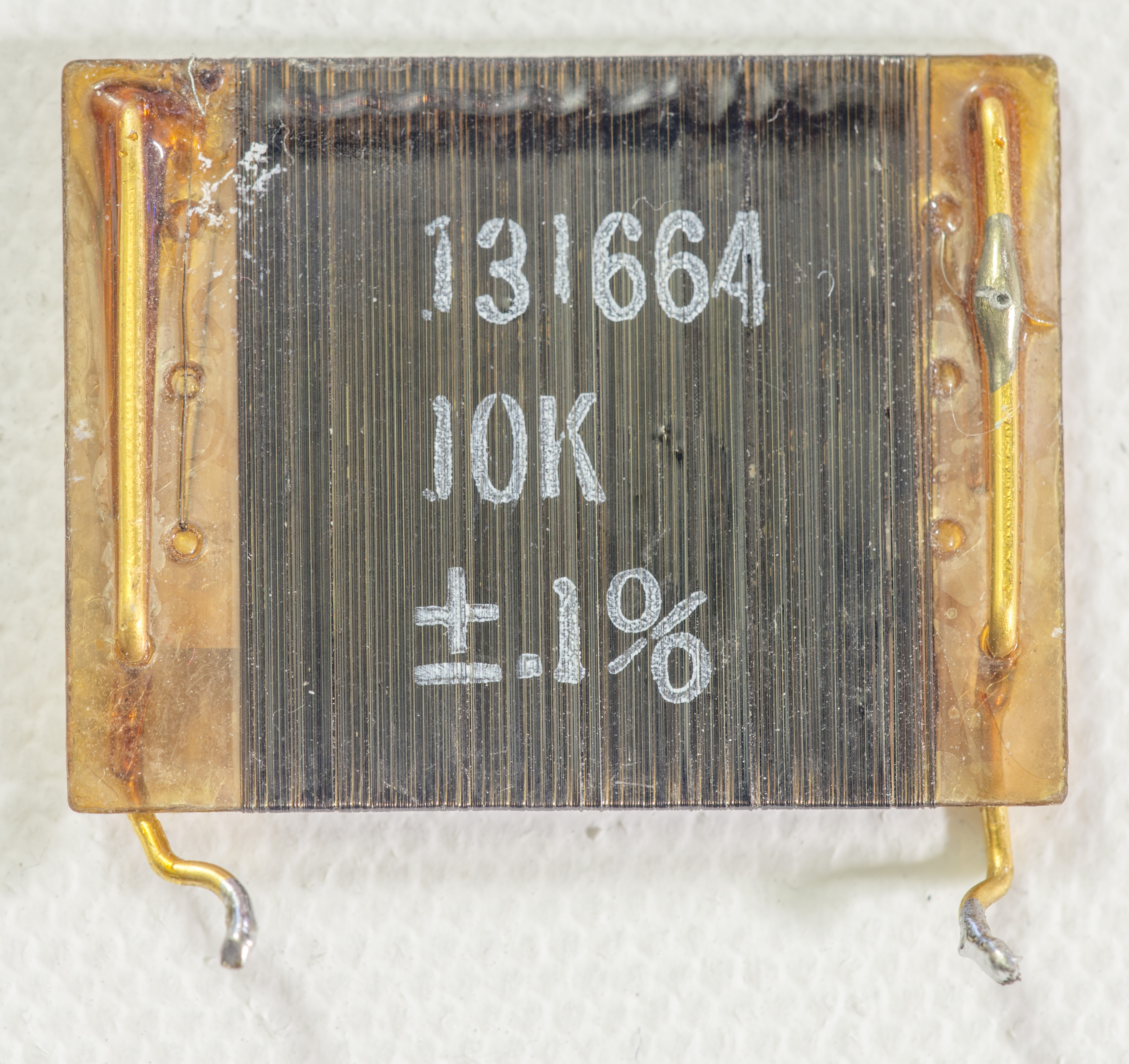  |
| Caddock TF020R ± 5 ppm/°C 7 | 20 kΩ | 2002-6 | -2.26 ppm/K | log |
| PTF56 15ppm spec, #9 | 75 KΩ | 2002-6 | -2.0 ppm/K | |
| Caddock TF020R ± 5 ppm/°C 3 | 500 kΩ | 3458A | -1.82 ppm/K | log |
| Caddock TF020R ± 5 ppm/°C 1C | 100 kΩ | 2002-4 | -1.43 ppm/K | log |
| 3458AR HP A1 shunt | 9 Ω | 2002-6 | -1.375 ppm/K | |
| S102 from eBay | 634.00 Ω | 2002-6 | -1.3…-1.56 ppm/K | |
| VPG Z202T | 10 KΩ | 2002-6 | -1.28 ppm/K |  |
| Caddock TF020R ± 5 ppm/°C 5 | 24 kΩ | 3458A | -1.28 ppm/K | log |
| S102 from eBay | 634.00 Ω | 2002-4 | -1.2…1.25 ppm/K | |
| VPG Z202T | 10 KΩ | 2002-4 | -1.18 ppm/K | 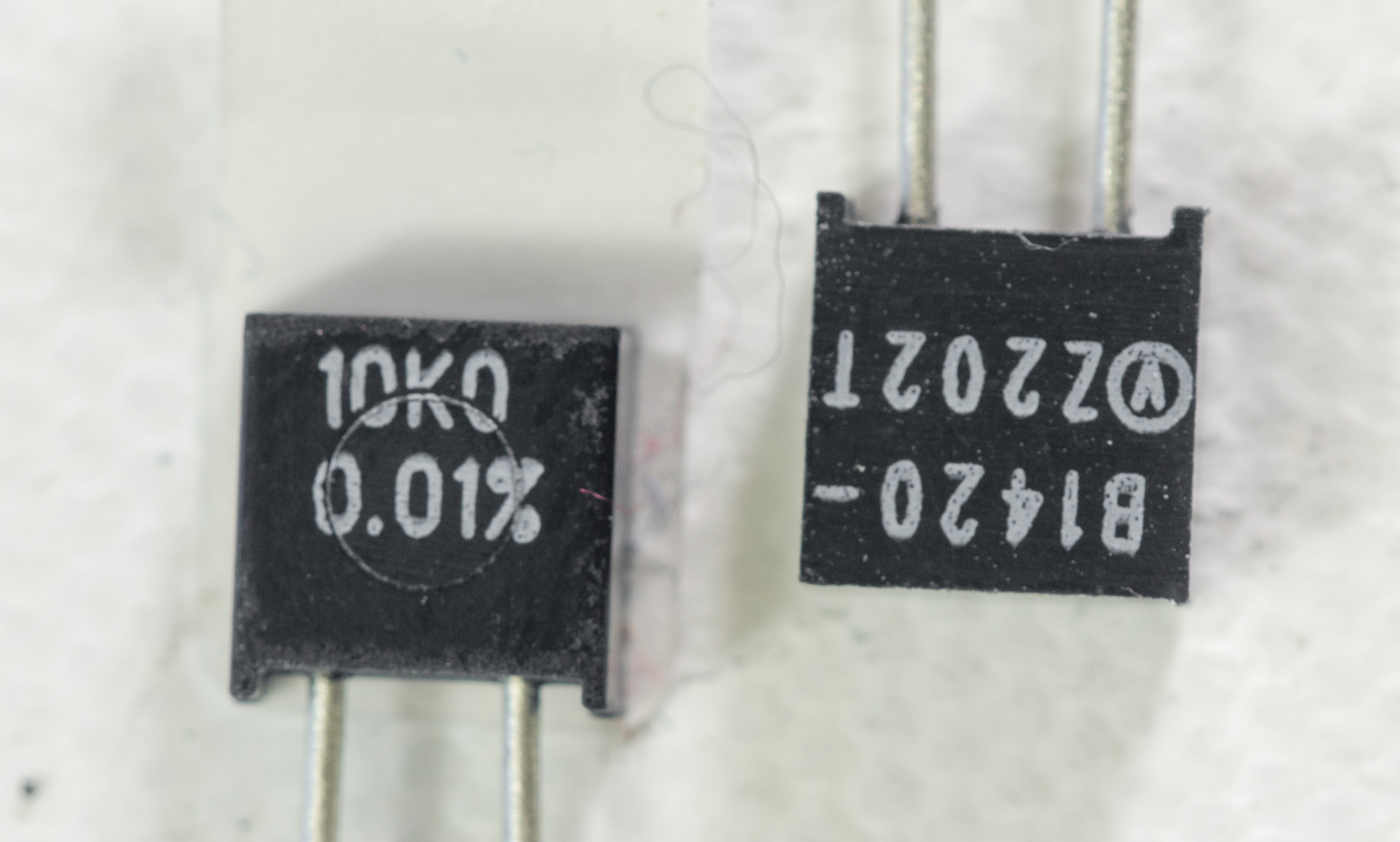 |
| 2xVPG S102 | 40.96 KΩ/2 | 3458A | -1.15 ppm/K | 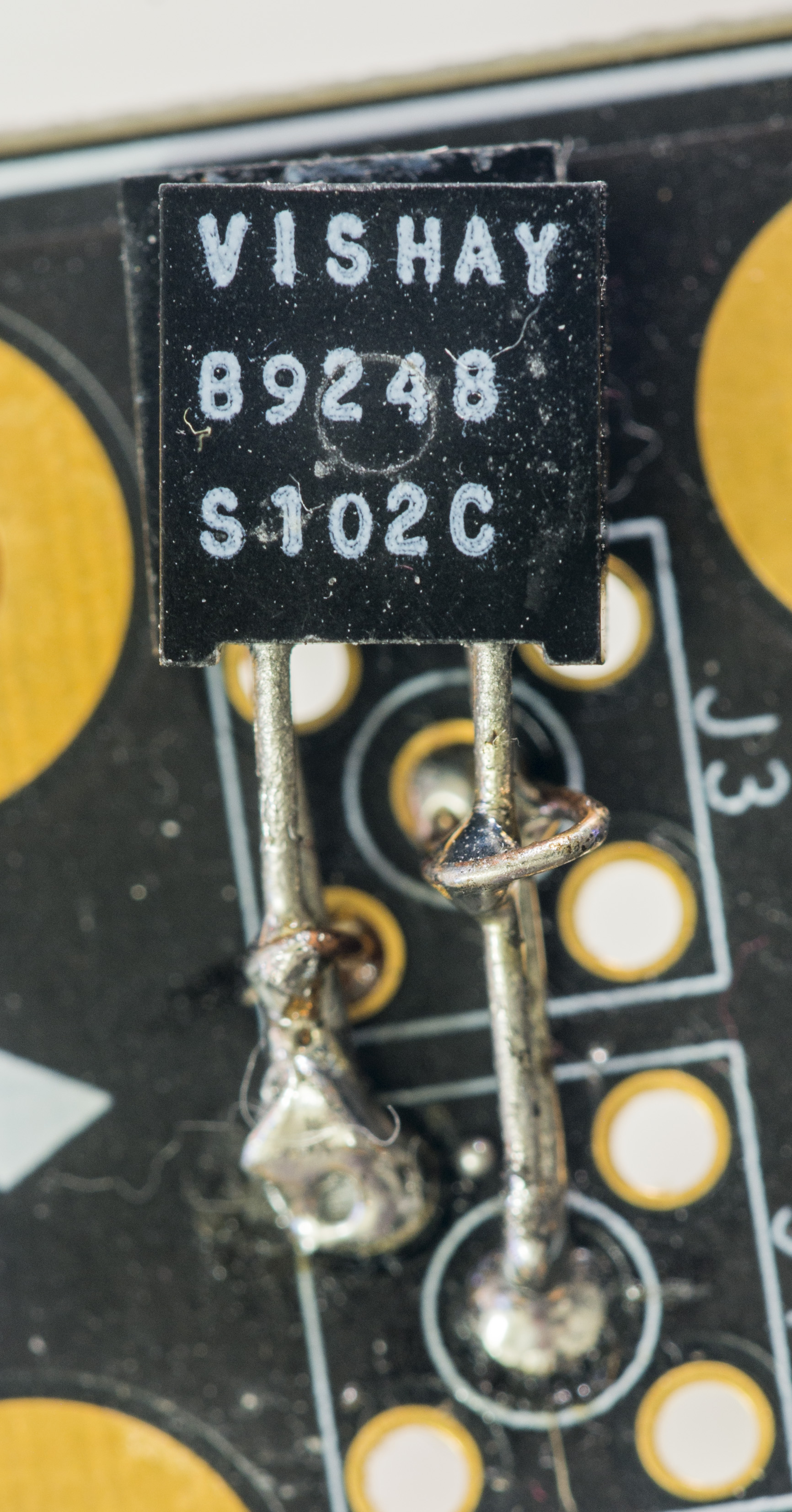 |
| VPG VPR221Z 1% spec 2.6ppm | 1 Ω | 2002-4 | -0.86…-1.47 ppm/K |  |
| Caddock TF020R ± 5 ppm/°C 12 | 1 kΩ | 3458A | -0.96 ppm/K | log |
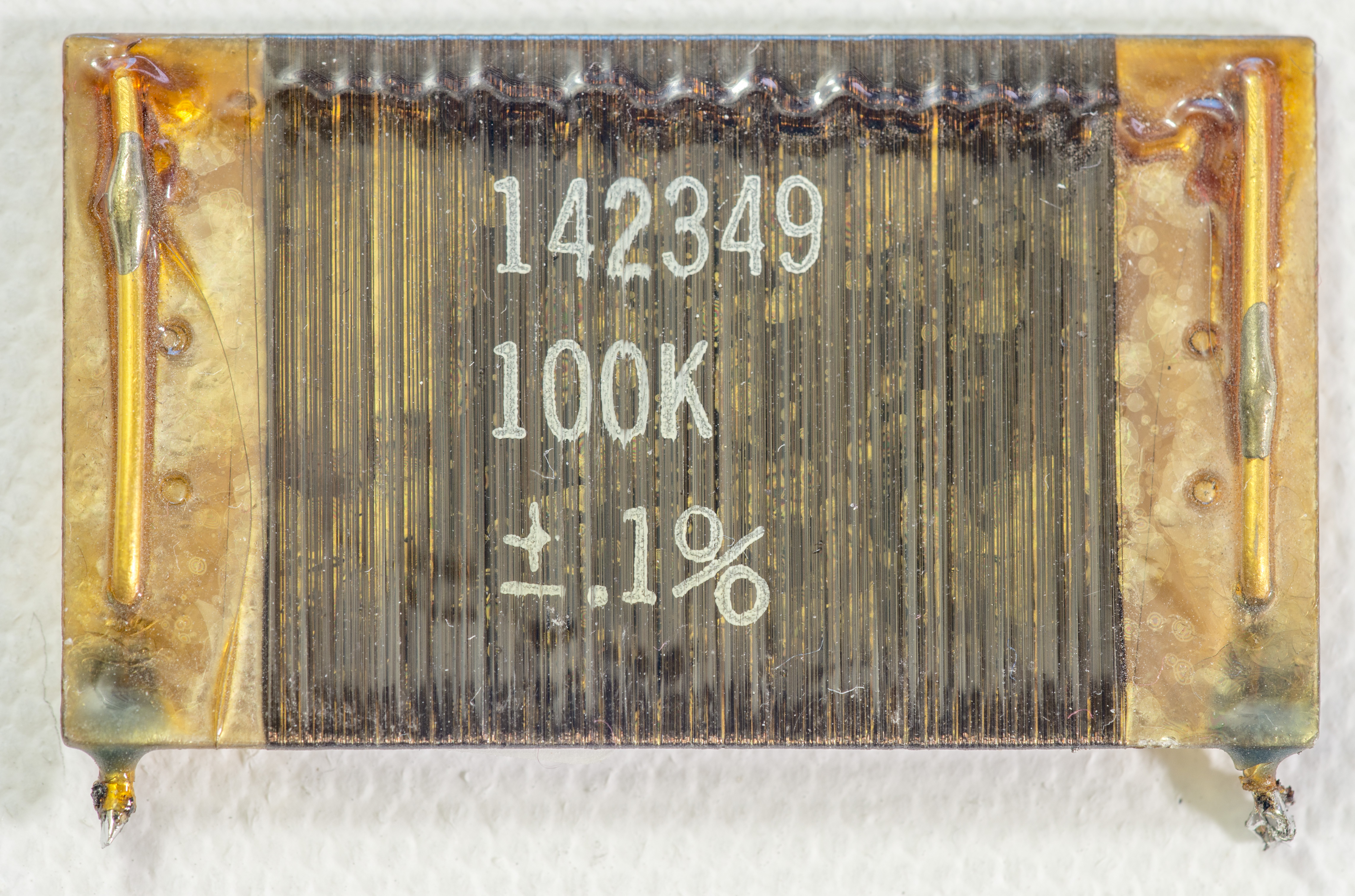
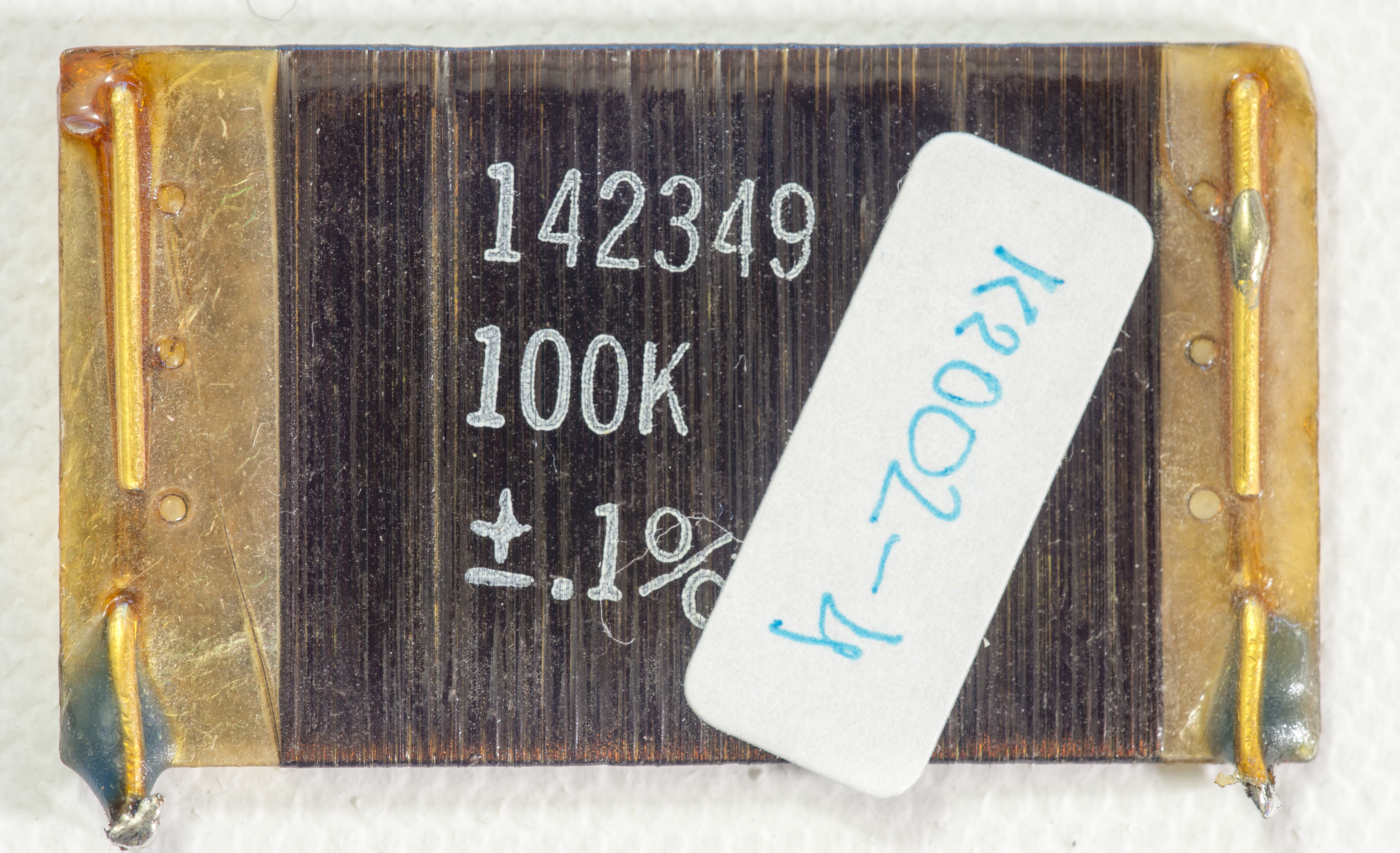
| VPG VHP202Z 0.005% | 190 Ω | 2002-6 | -0.95 ppm/K -0.84 ppm/K 0918 2002-4 |   |
| VPG VHP202Z 19R 0.05% | 19 Ω | 3458A | -0.9 ppm/K | 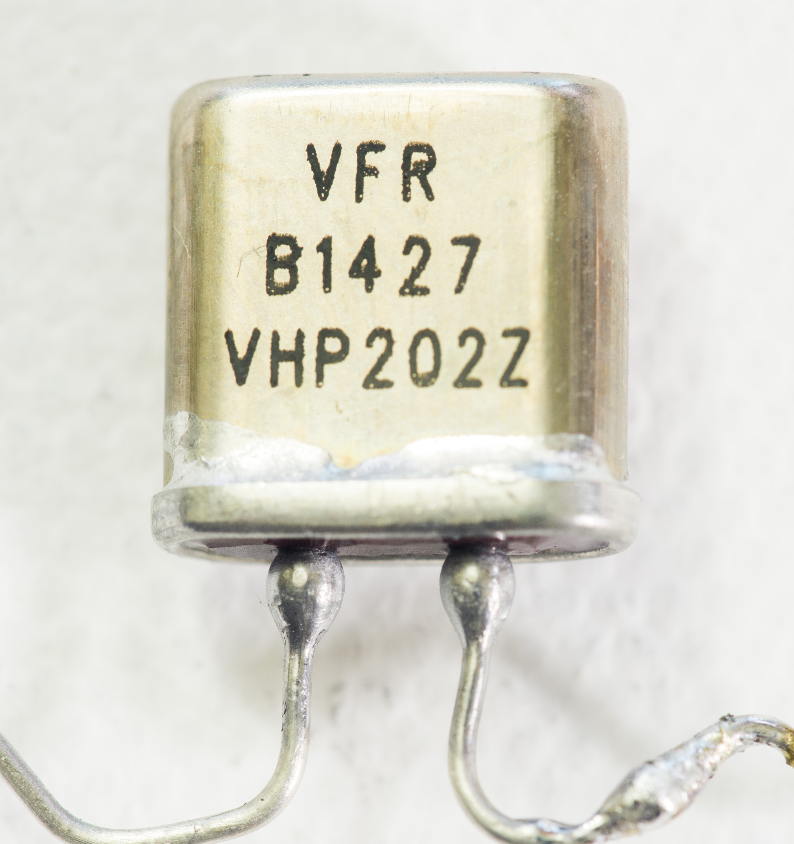 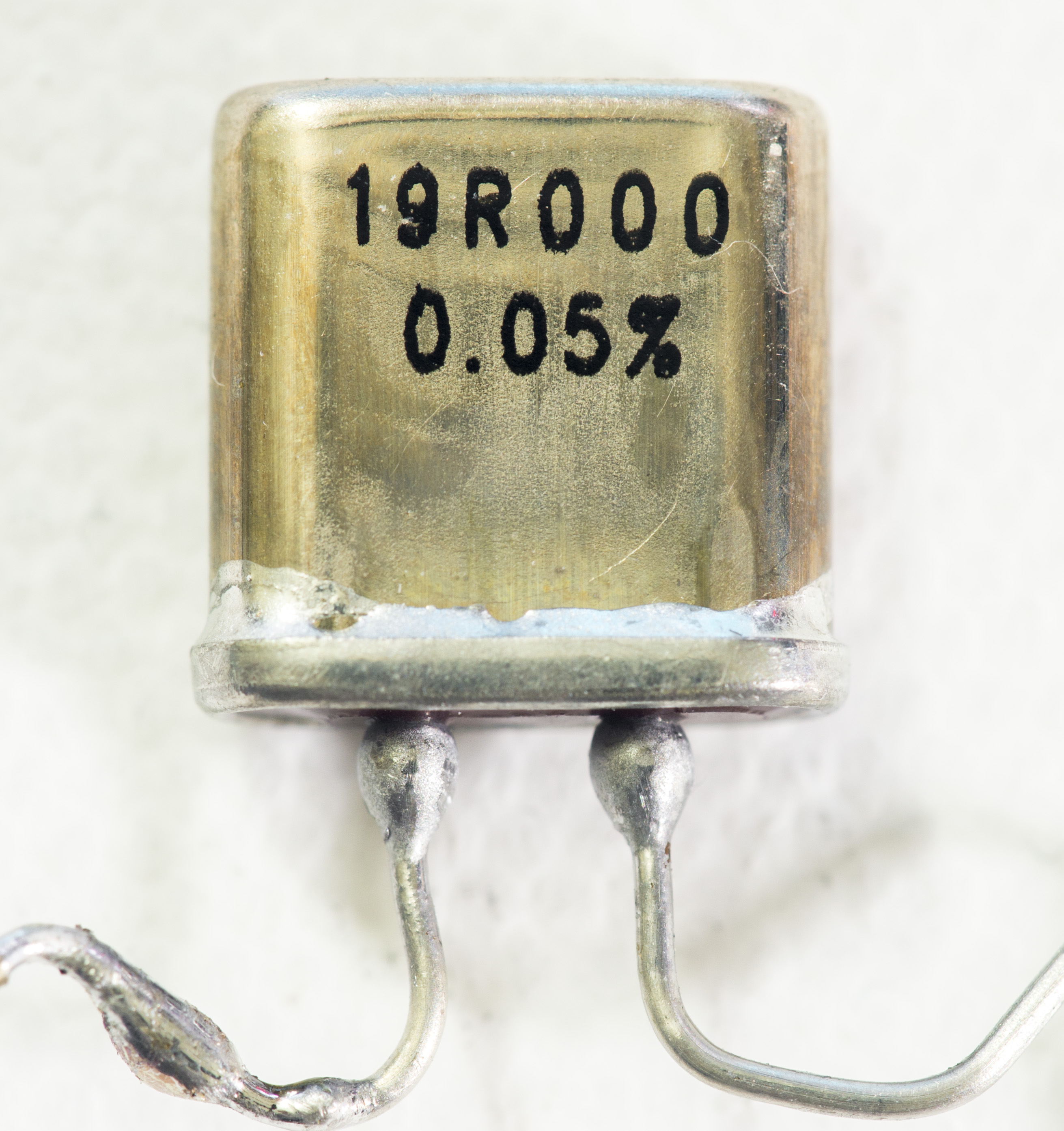 |
| Resistor 7+9 series, combined | 29 kΩ | 2002-6 | -0.77 ppm/K | log |
| Caddock TF020R ± 5 ppm/°C 4B | 25 kΩ | 3458B | -0.74 ppm/K | log |
| VPG S102 | 120.00 Ω | 3458A | -0.65 ppm/K | |
| Soviet S5-61 spec 5ppm | 11.1 KΩ | 2002-4 | -0.6ppm/K |   |
| VPG VHP202ZT 0.05% | 120 Ω | 3458A | -0.55 ppm/K | 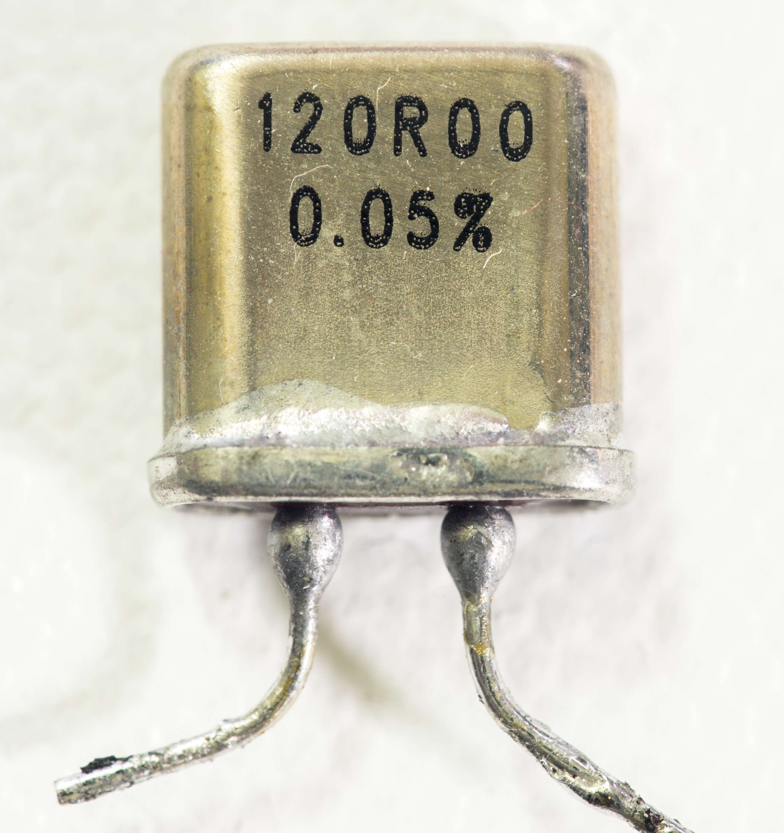 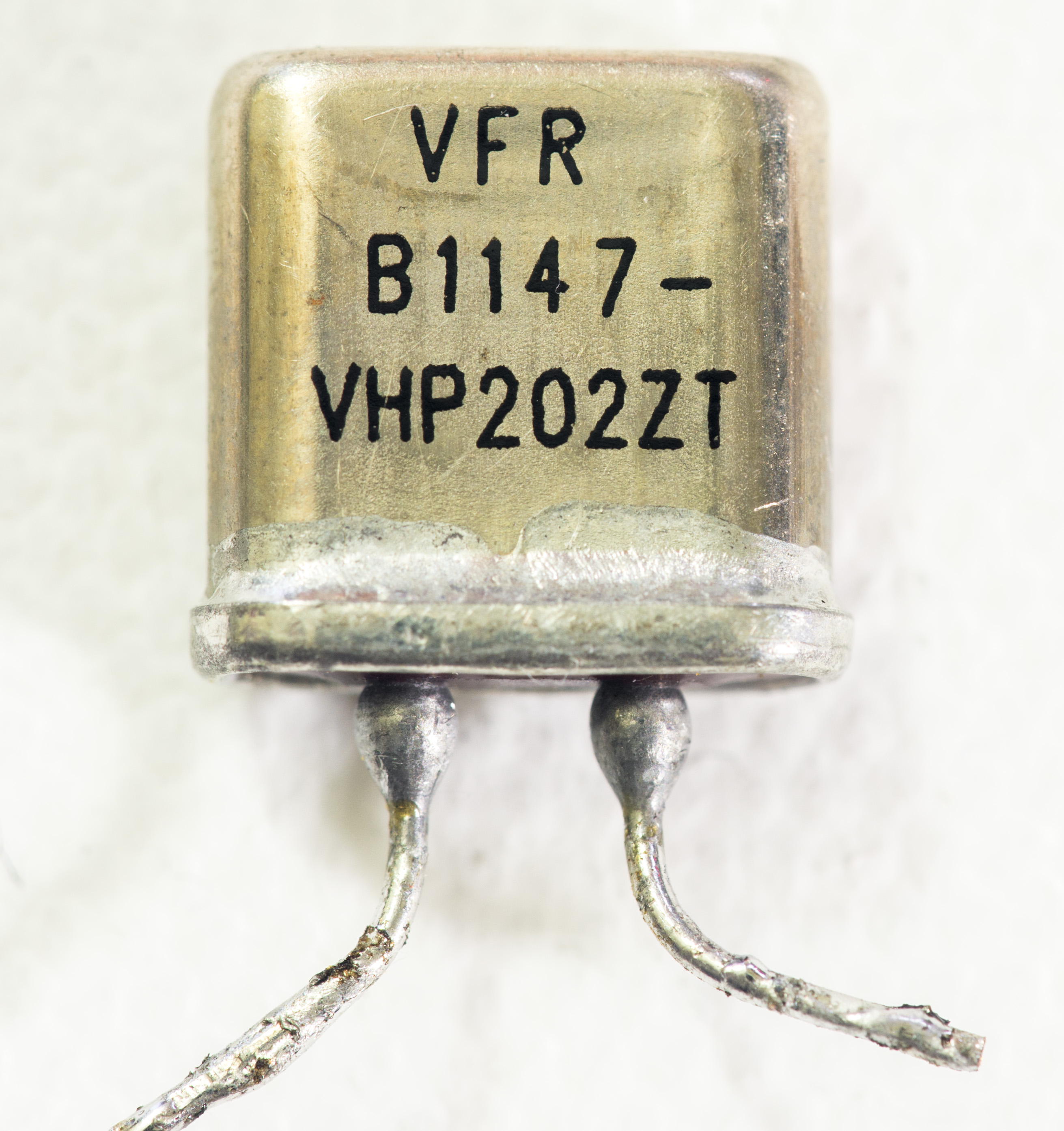 |
| VPG VHA518 0.005% | 100 KΩ | 3458B | -0.51 ppm/K | 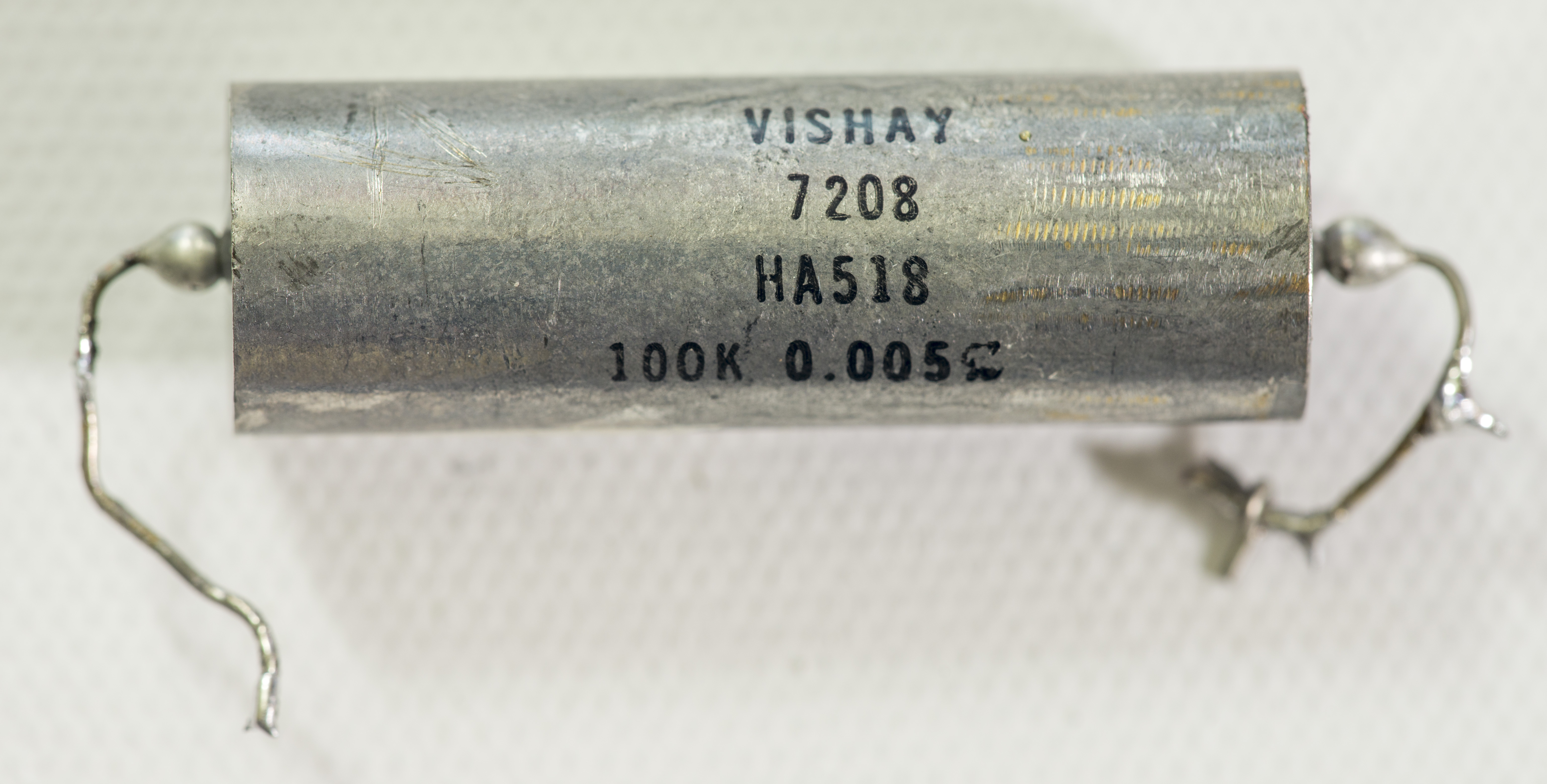 |
| Caddock TF020R ± 5 ppm/°C 4A | 25 kΩ | 2002-6 | -0.40 ppm/K | log |
| VPG CSNG #2 | 2.5 Ω | 3458A | -0.3 ppm/K | 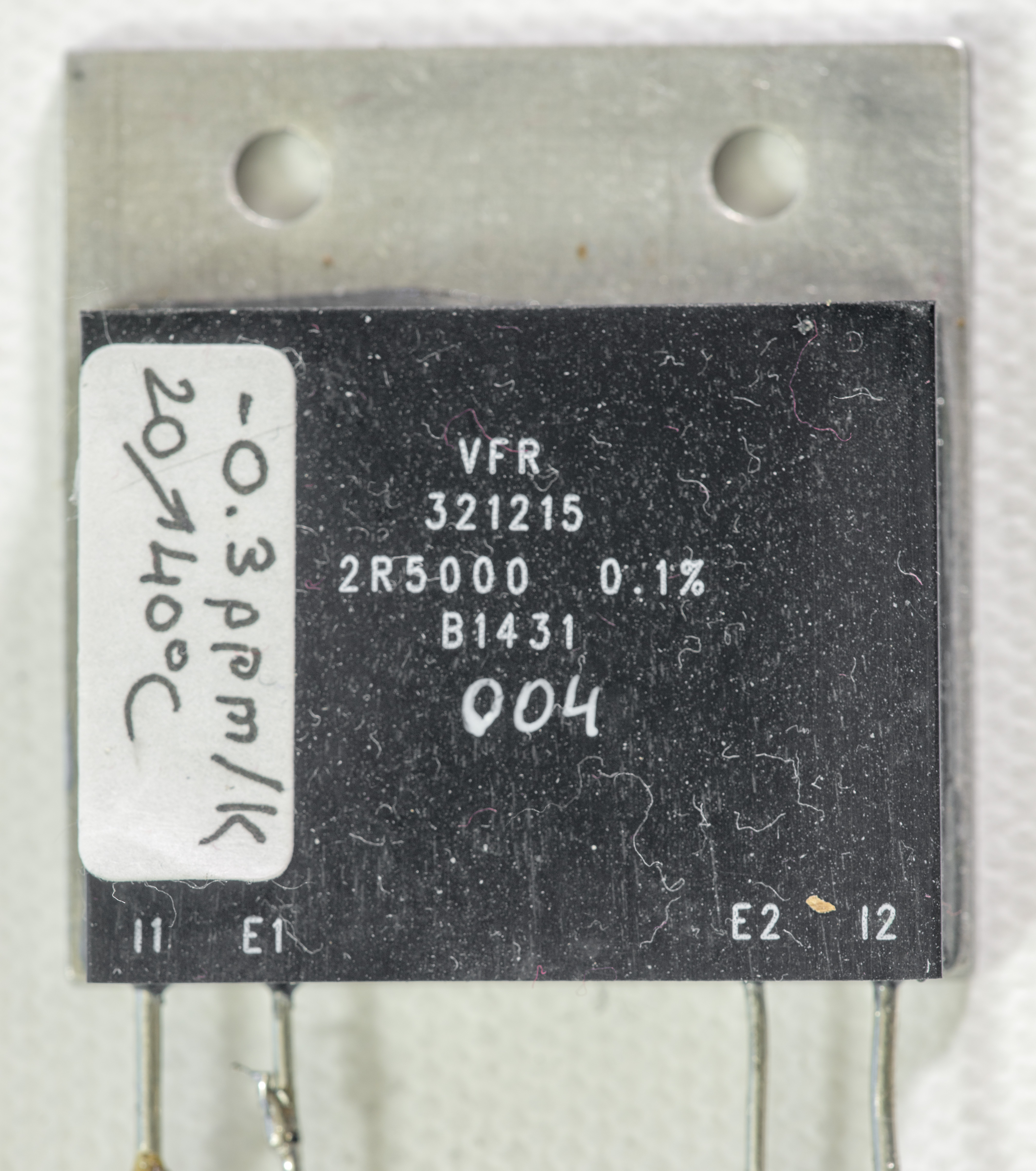 |
| Fluke WW 146530 | 40 KΩ | 2002-4 | -0.3 ppm/K | 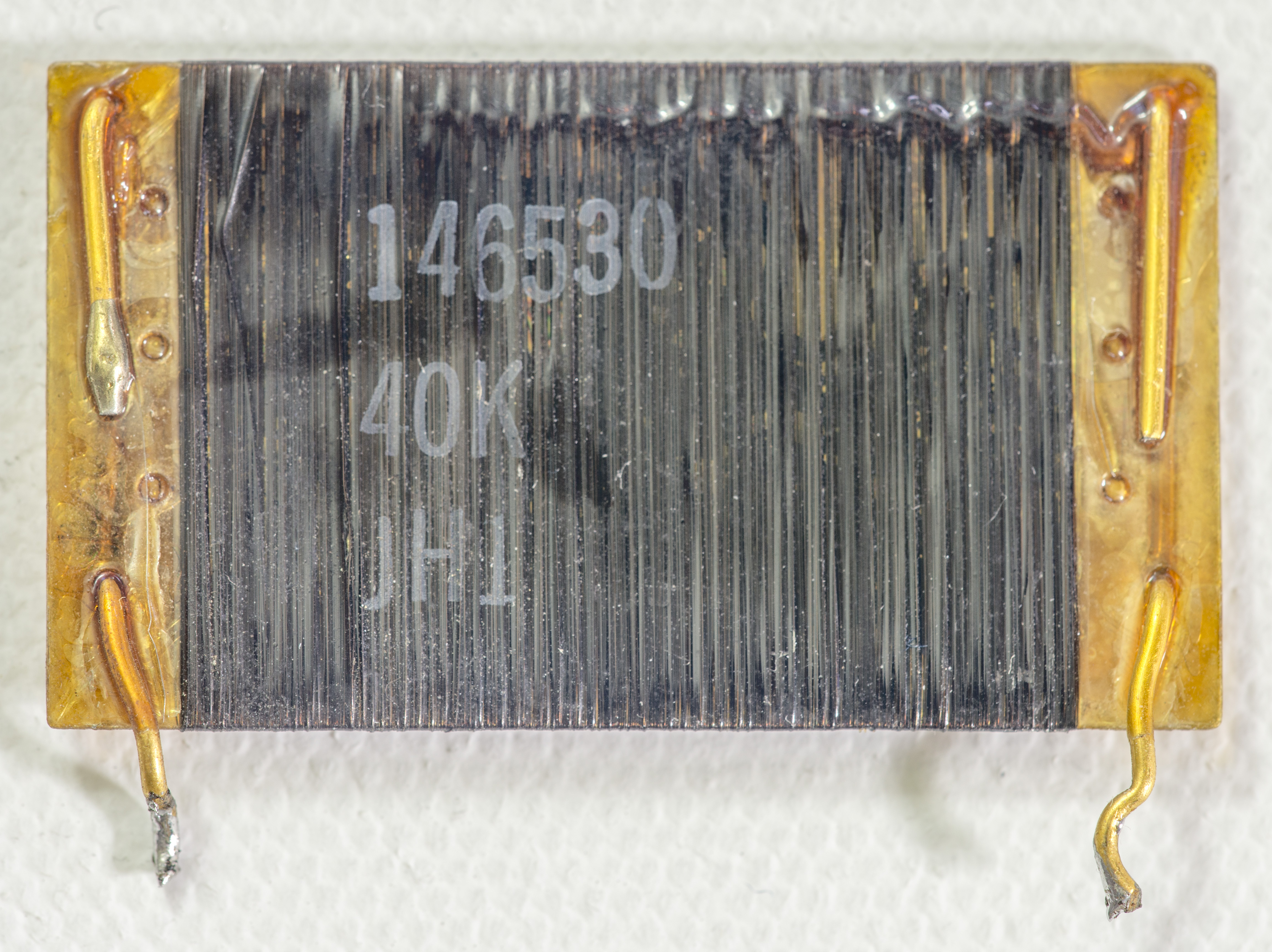 |
| VPG VHP101 0.005% 0.3ppm spec | 1.9 KΩ | 3458B | -0.25 ppm/K |   |
| VPG CSNG #1 | 2.5 Ω | 3458A | -0.175 ppm/K |  |
| HP 3458A A1 VPG 301358 0.5% A1R307 | 300 Ω | 2002-6 | -0.15 ppm/K |  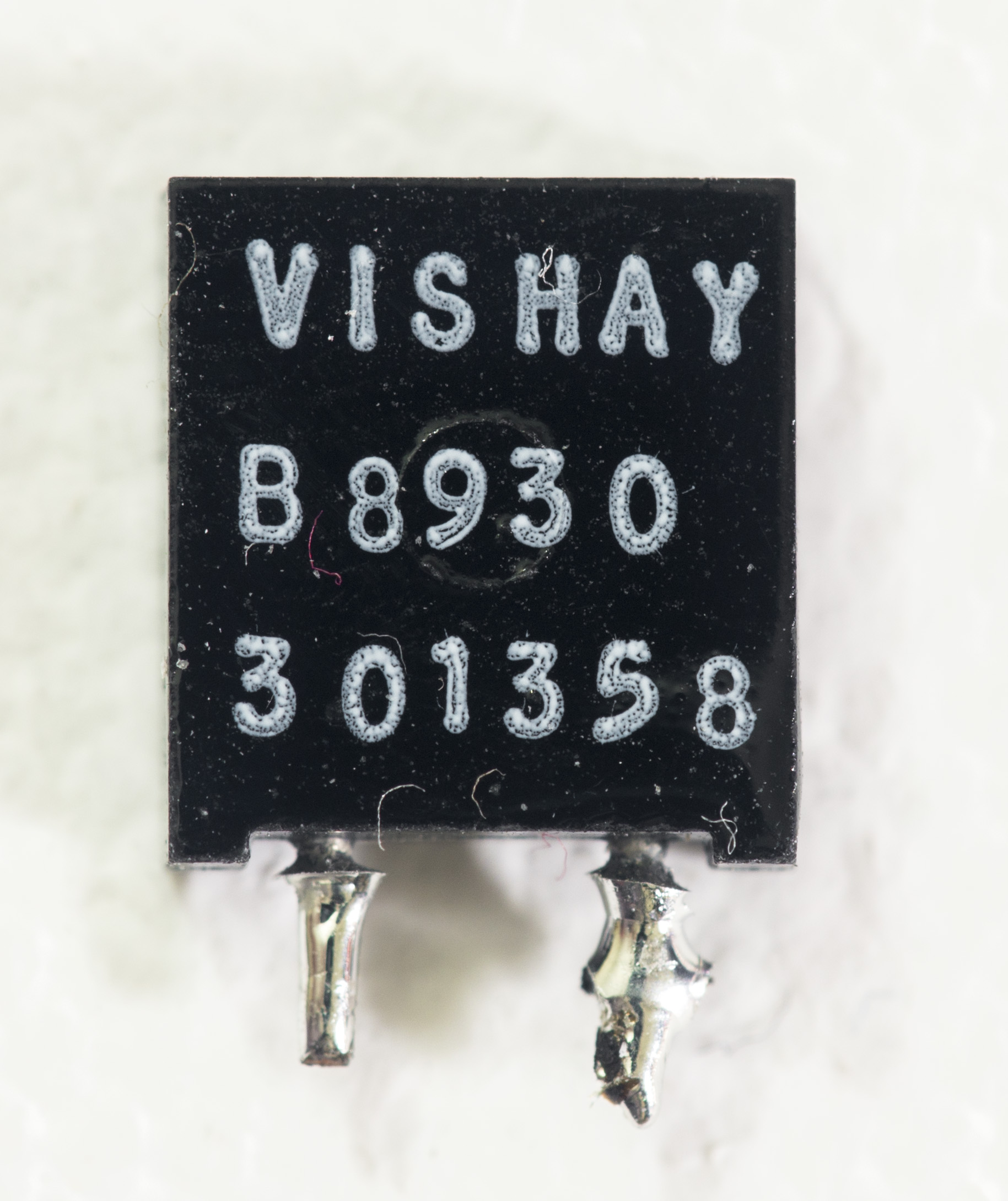 |
| VPG VHP101 0.005% with PMO and matching | 19 KΩ | 2002-6 | -0.105 ppm/K | 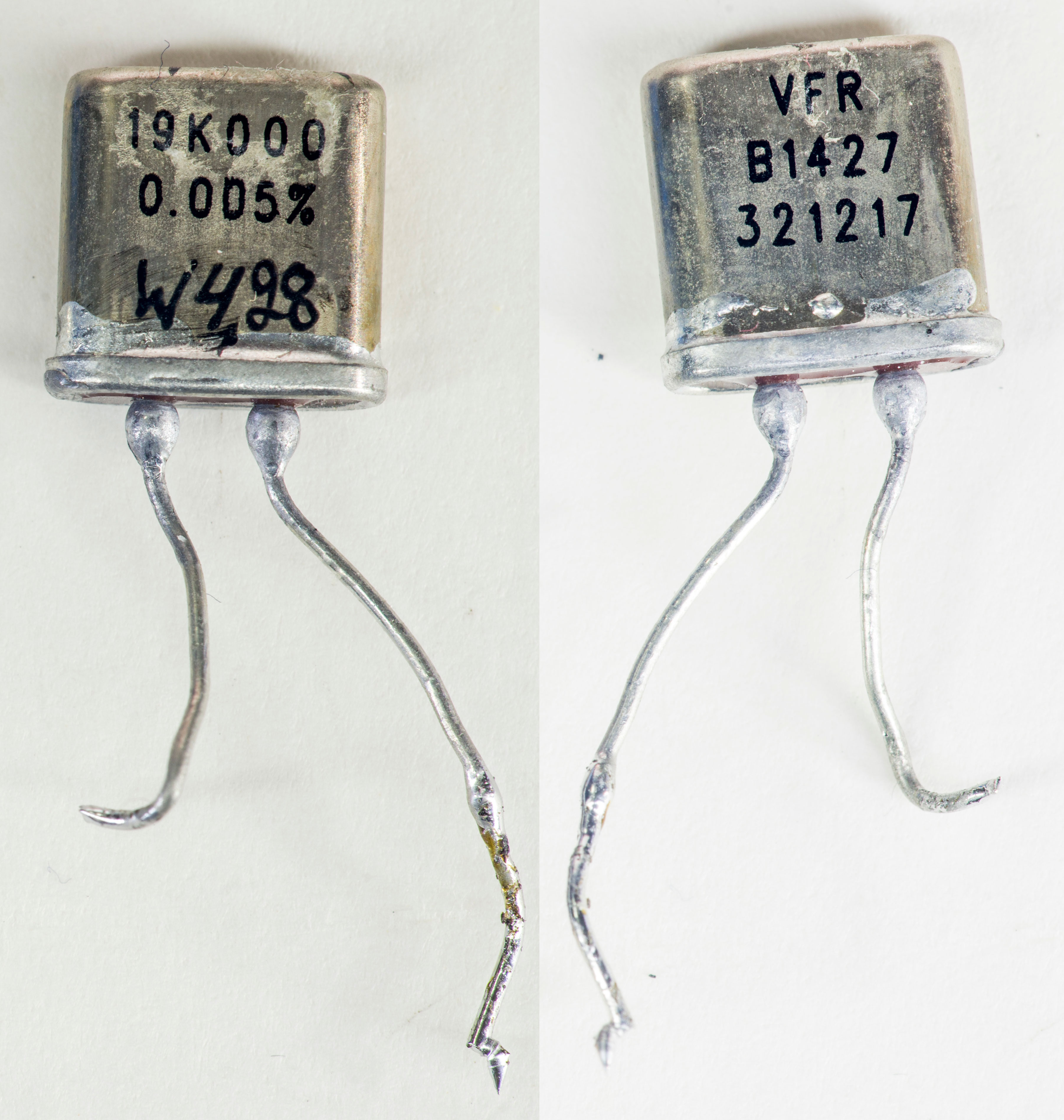 |
| PTF56 15ppm spec, #5 | 75 KΩ | 2002-6 | -0.13…+0.18 ppm/K | |
| VPG VHP101 0.005% 0.3ppm spec | 95 KΩ | 2002-4 | <-0.1 ppm/K average |  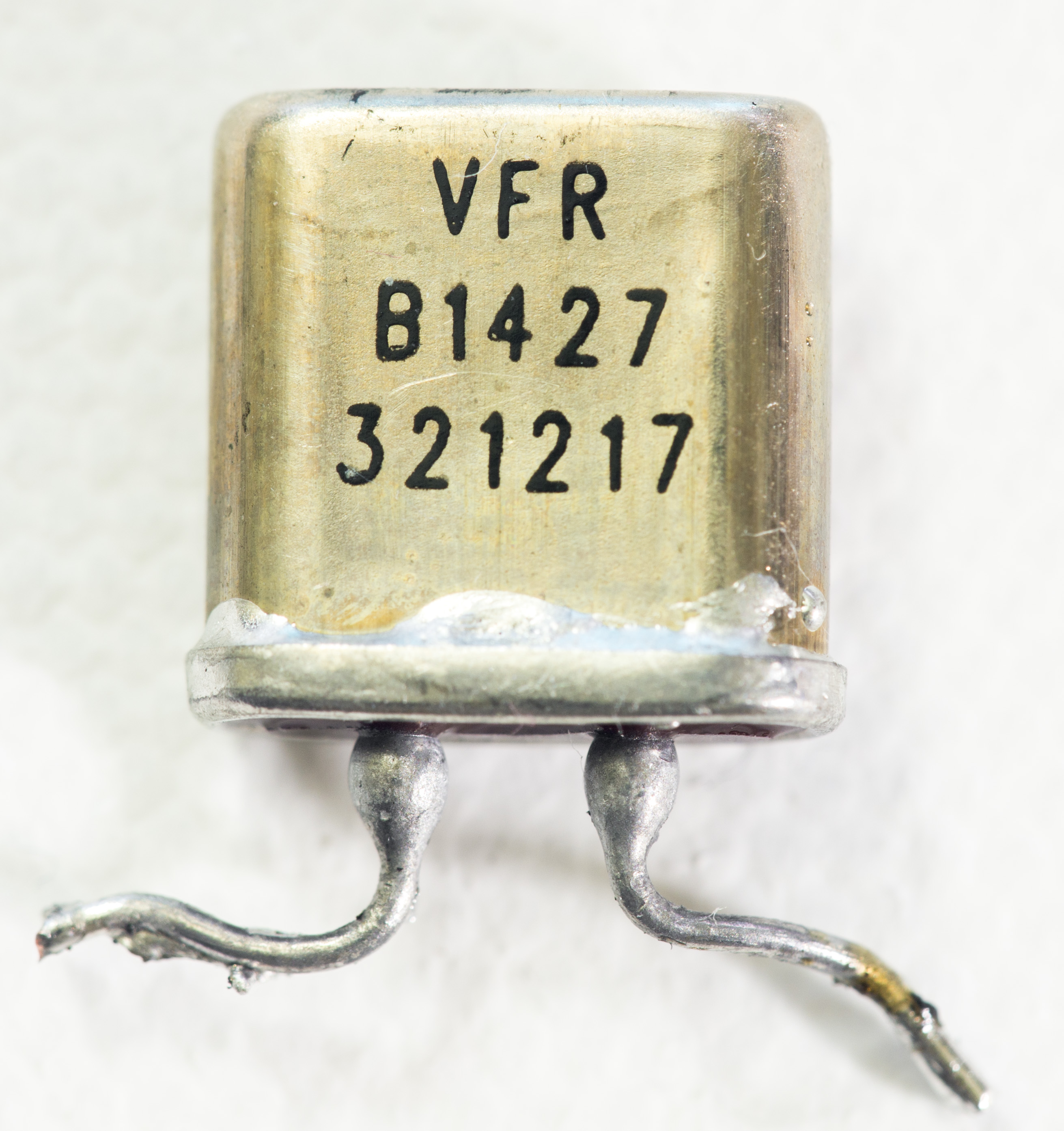 |
| RIEDON USR2G-15KX1 1ppm/K spec | 15 KΩ | 3458A | +0.04 ppm/K | 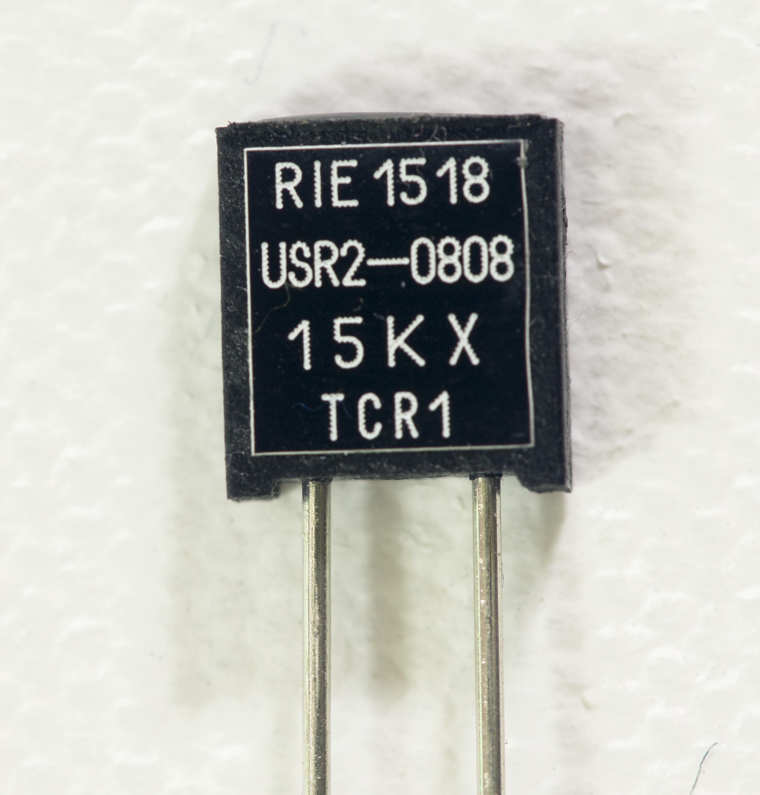 |
| SFERNICE | 30 KΩ | 2002-4 | +0.15 ppm/K | |
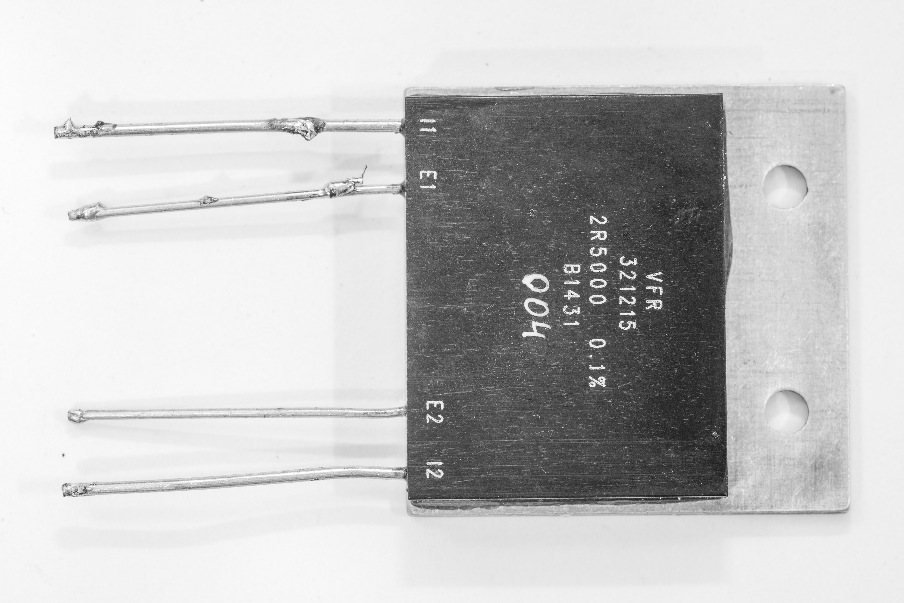
| VPG 321219 VHA518-11 1ppm spec 0.01% | 1 MΩ | 3458A | +0.19 ppm/K | 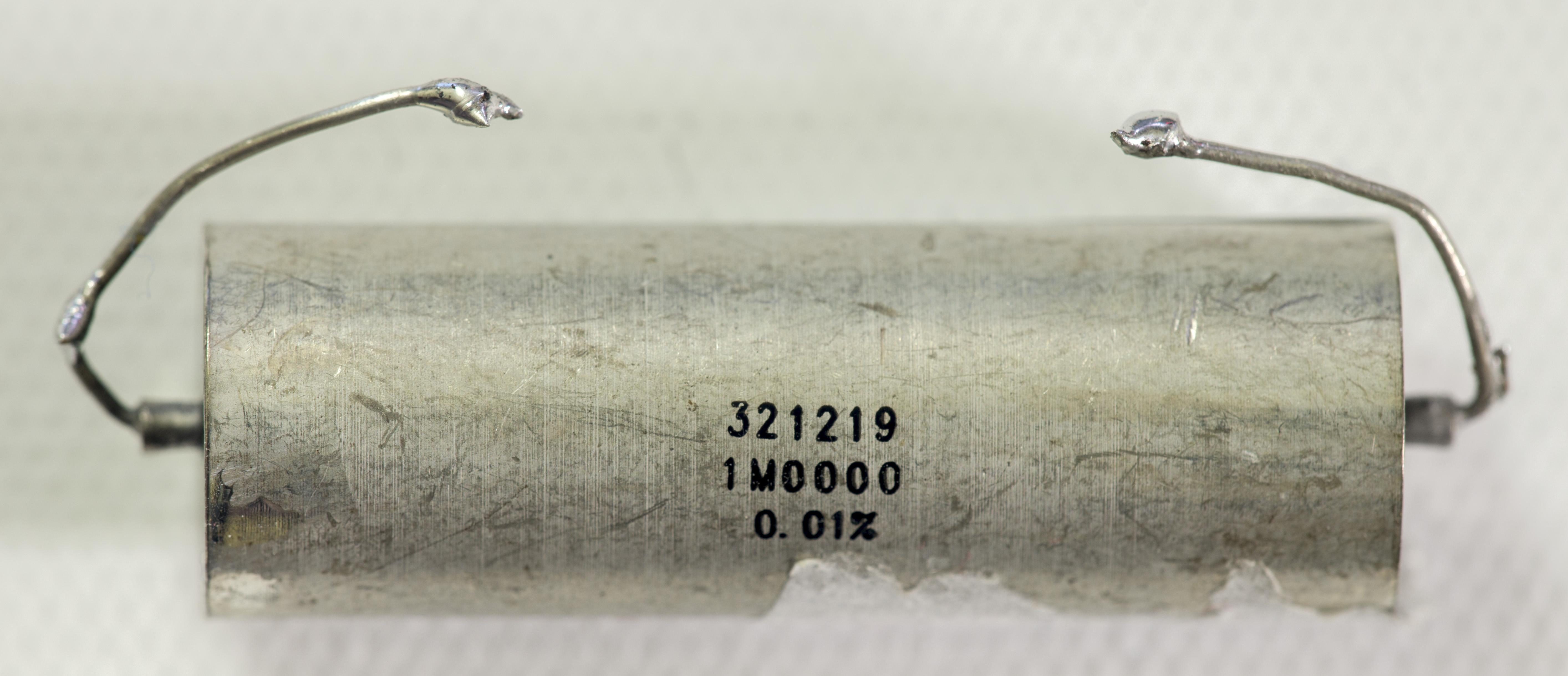 |
| VPG CSNG #1 from eBay | 0.1 Ω | 3458A | +0.55 ppm/K |  |
| Caddock TF020R ± 5 ppm/°C 1E | 100 kΩ | 3458B | +0.74 ppm/K | log |
| CADDOCK USF340 | 500 KΩ | 3458B | +0.78 ppm/K |  |
| PRC HR3716N from MC-7 set | 1 MΩ | 2002-4 | +0.8 ppm/K | 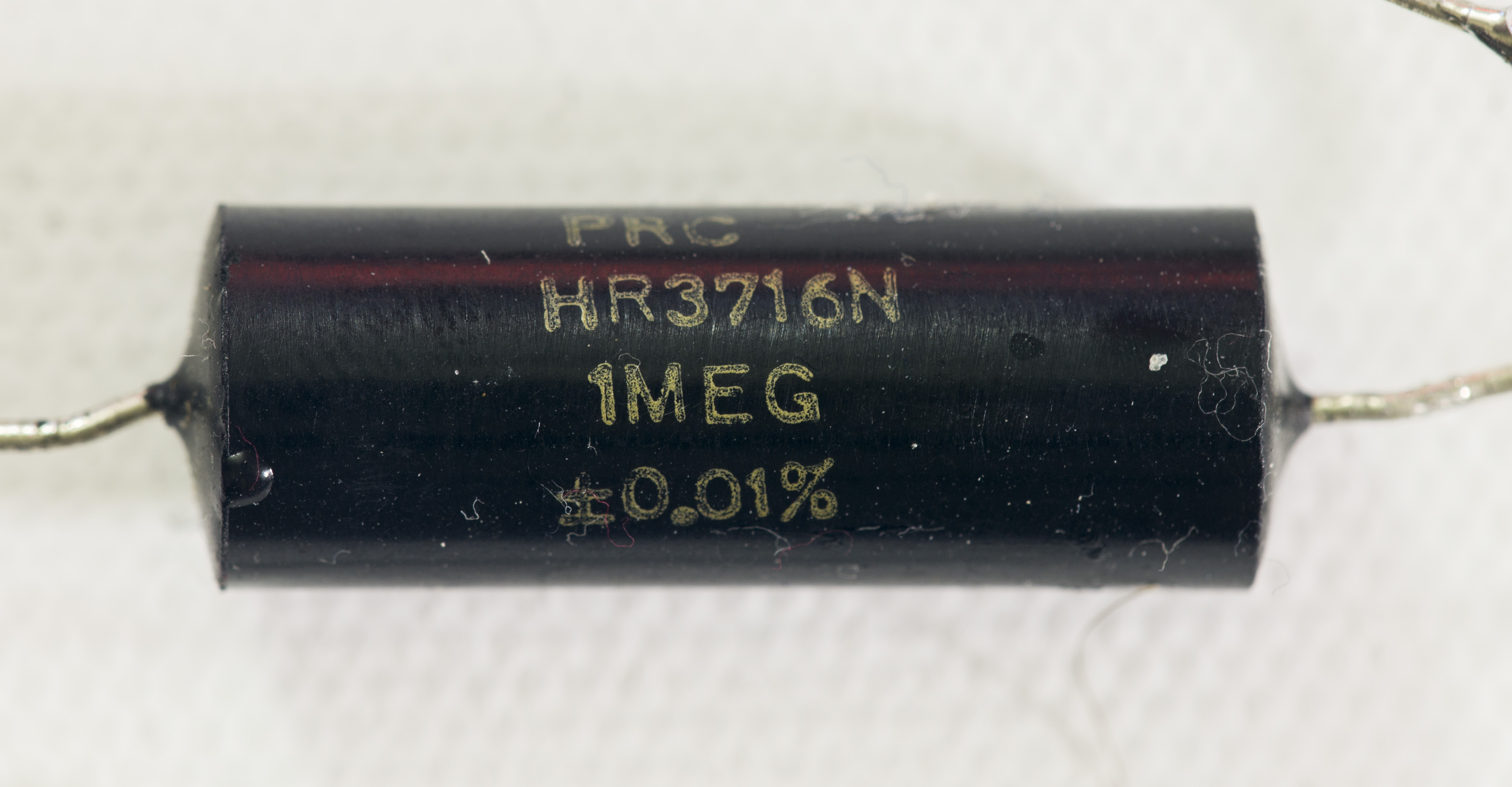 |
| PRC HR3716N from MC-7 set | 1 KΩ | 3458A | +1.25 ppm/K | |
| HP 3458A A1 0.1% 1.3ppm spec from dead A1 | 40 KΩ | 2002-6 | +1.4 ppm/K | 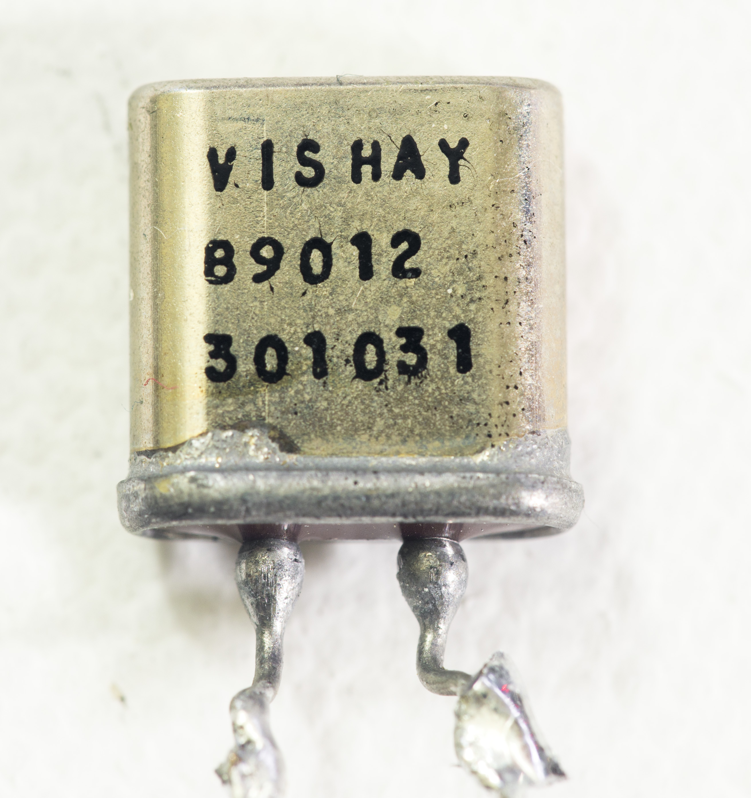 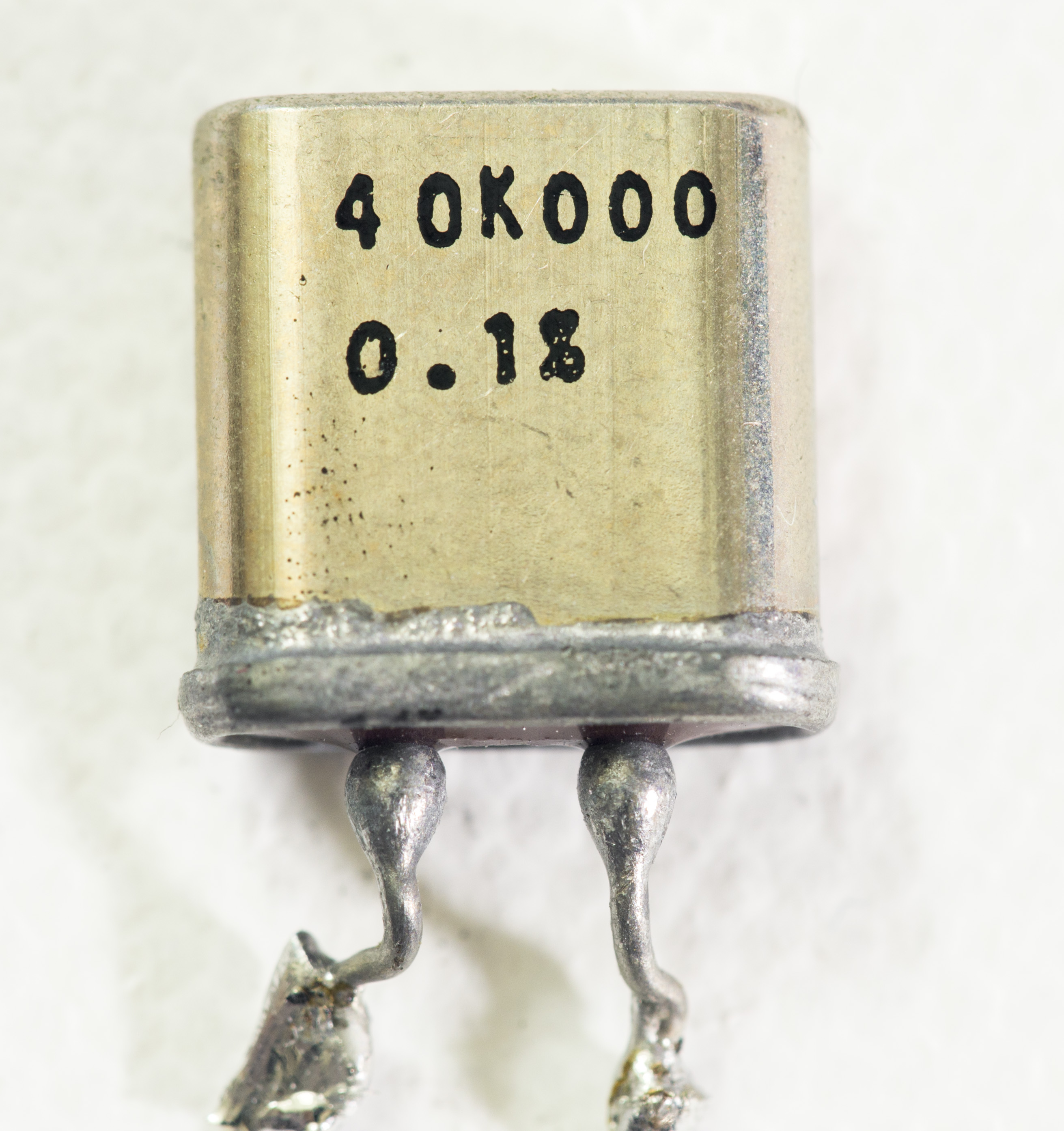 |
| HP 3458A A1 0.1% 1.3ppm spec from dead A1 | 40 KΩ | 2002-4 | +1.6 ppm/K | |
| PRC HR3716N from MC-7 set | 100 KΩ | 2002-6 | +1.5 ppm/K | 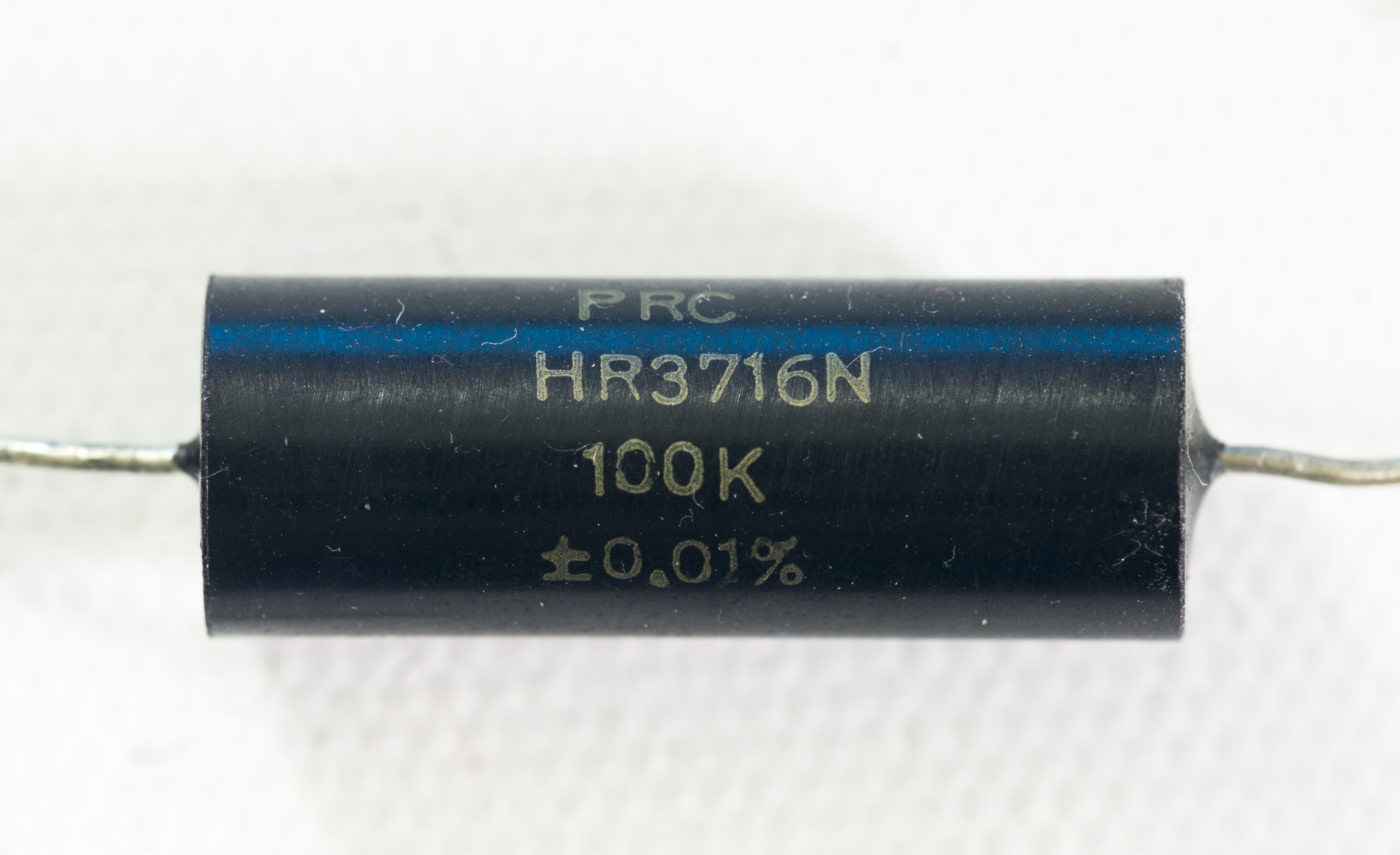 |
| AE from eBay | 9.000 Ω | 3458A | +1.5…+0.94 ppm/K | |
| 3458AR HP shunt | 1 Ω | 2002-4 | +1.7 ppm/K | |
| Caddock TF020R ± 5 ppm/°C 1A | 100 kΩ | 3458B | +1.71 ppm/K | log |
| 3458AR 500K | 500 KΩ | 2002-6 | +1.86 ppm/K | |
| Caddock TF020R ± 5 ppm/°C 9 | 9 kΩ | 3458B | +2.18 ppm/K | log |
| Old black VWW 0.1% | 300 Ω | 3458A | +2.2 ppm/K |  |
| VPG VPR5 #3 from eBay | 1 Ω | 2002-6 | +2.65 ppm/K | |
| MZNRE1801 network 5-last | 1 KΩ | 3458A | +2.75 ppm/K | 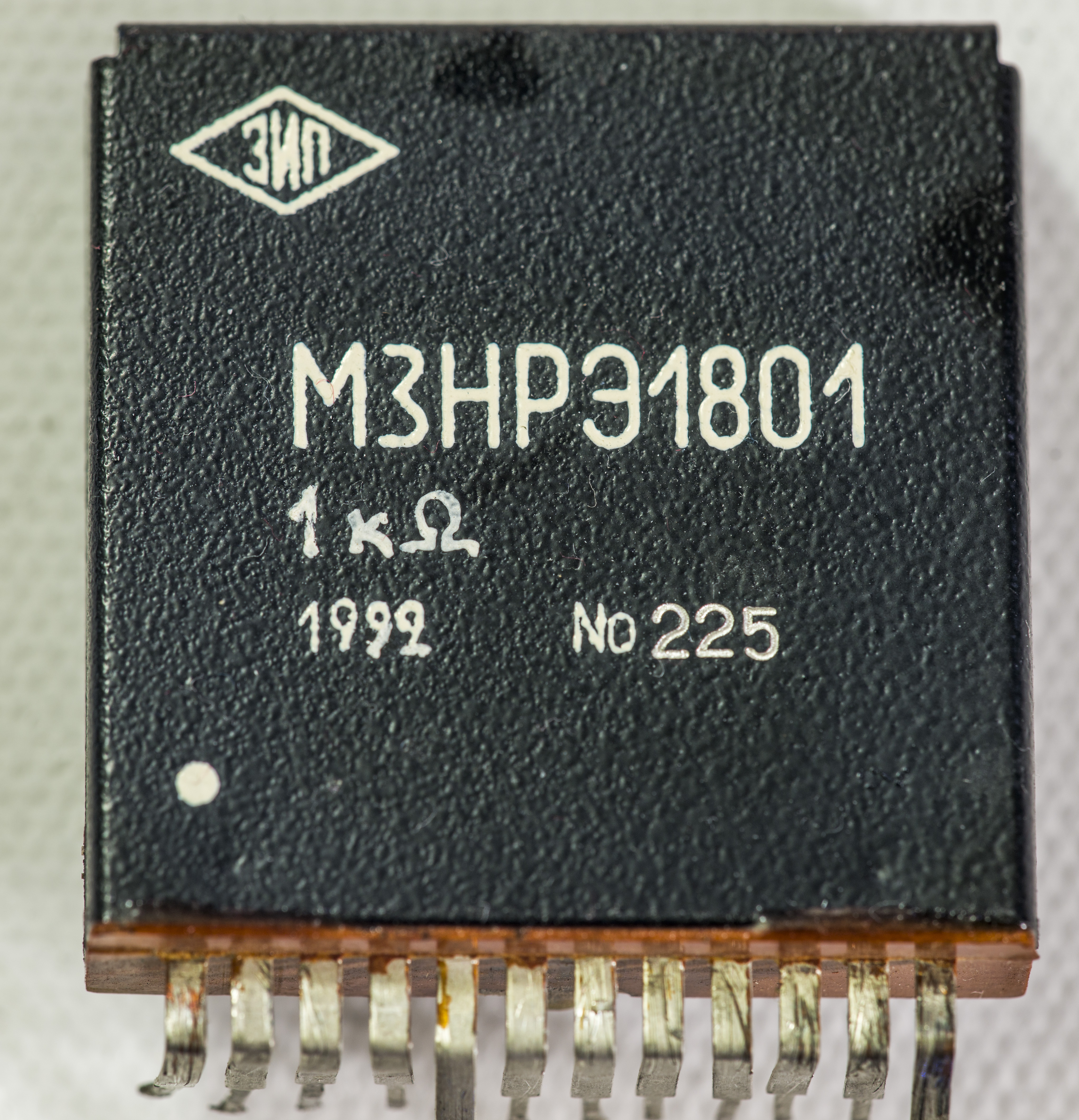 |
| Caddock TF020R ± 5 ppm/°C 1D | 100 kΩ | 2002-6 | +2.75 ppm/K | log |
| HP 3458A HV-divider | 10 MΩ | 2002-6 | +2.9 ppm/K |  |
| Caddock TF020R ± 5 ppm/°C 10 | 5 kΩ | 3458A | +2.99 ppm/K | log |
| HP 3458A HV-divider | 100 KΩ | 2002-4 | +3.2 ppm/K | |
| Caddock TF020R ± 5 ppm/°C 2 | 200 kΩ | 2002-6 | +3.20 ppm/K | log |
| VPG VPR5 #3 from eBay | 1 Ω | 3458A | +3.4 ppm/K |  |
| Caddock USF340 5ppm/K spec | 10 MΩ | 3458A | +3.4 ppm/K | 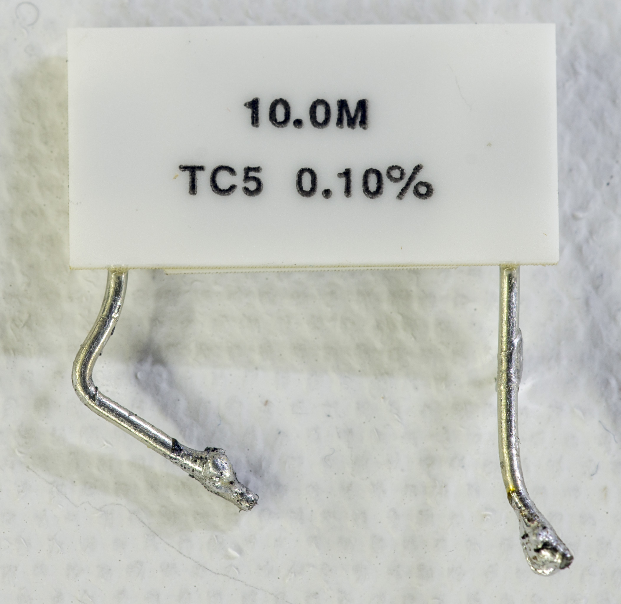  |
| Caddock MK120 ± 50 ppm/°C 11A | 100 Ω | 3458A | -3.43 ppm/K (box, non-linear) | log |
| Caddock TF020R ± 5 ppm/°C 8 | 18 kΩ | 2002-4 | +3.59 ppm/K | log |
| Caddock TF020R ± 5 ppm/°C 6 | 22 kΩ | 2002-4 | +3.80 ppm/K | log |
| soviet BMF S5-61 | 1.96 KΩ | 2002-6 | +3.95 ppm/K | |
| Caddock TF020R ± 5 ppm/°C 1B | 100 kΩ | 2002-4 | +4.09 ppm/K | log |
| 3458AR HP A1 shunt | 634 Ω | 2002-4 | +4.65 ppm/K | |
| HP 3458A shunt | 9 Ω | 2002-6 | +4.7 ppm/K | 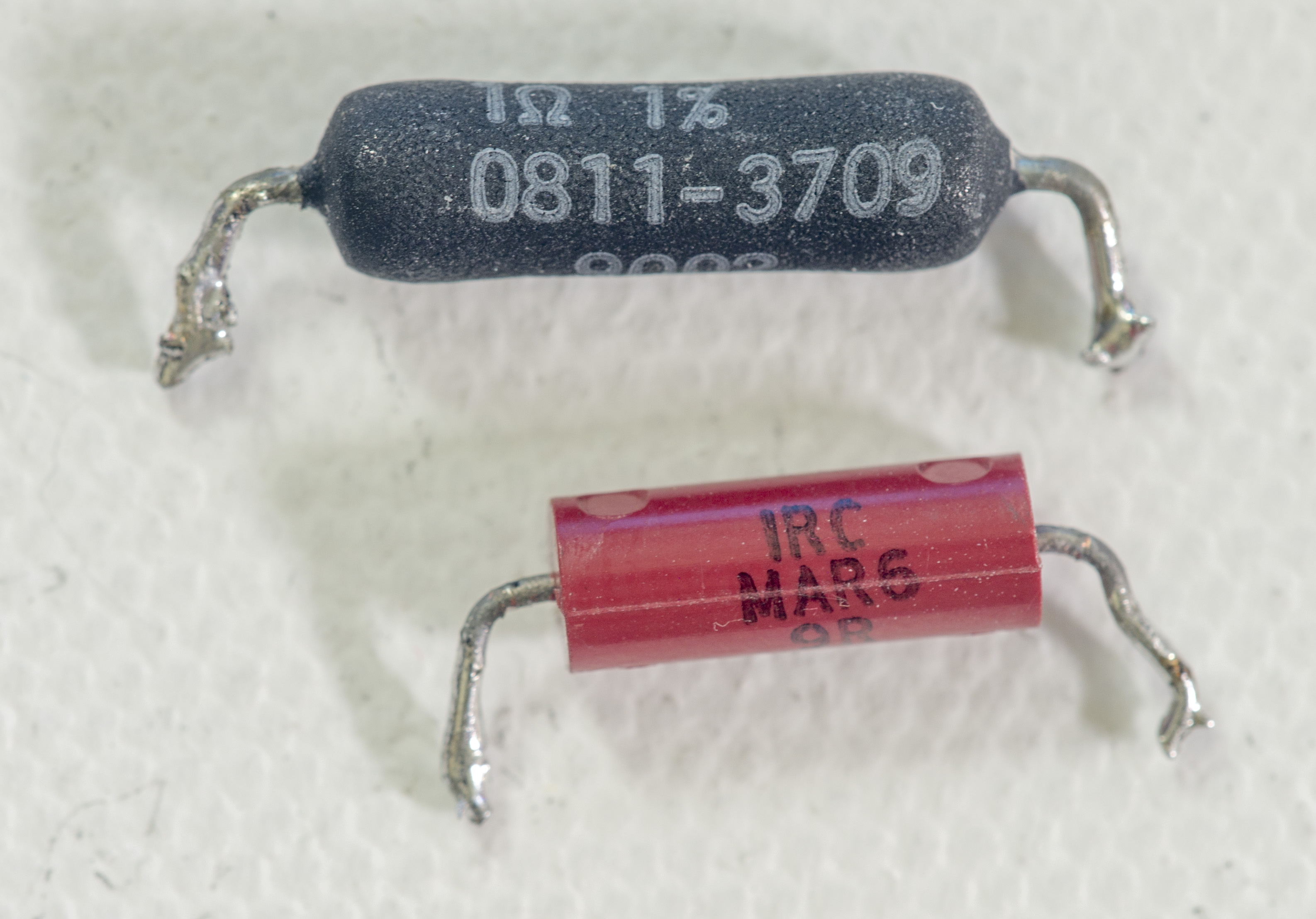 |
| Caddock MK120 ± 50 ppm/°C 11B | 100 Ω | 3458B | -4.85 ppm/K (box, non-linear) | log |
| VPG VPR5 #5 from eBay | 1 Ω | 3458A | +6.2 ppm/K | 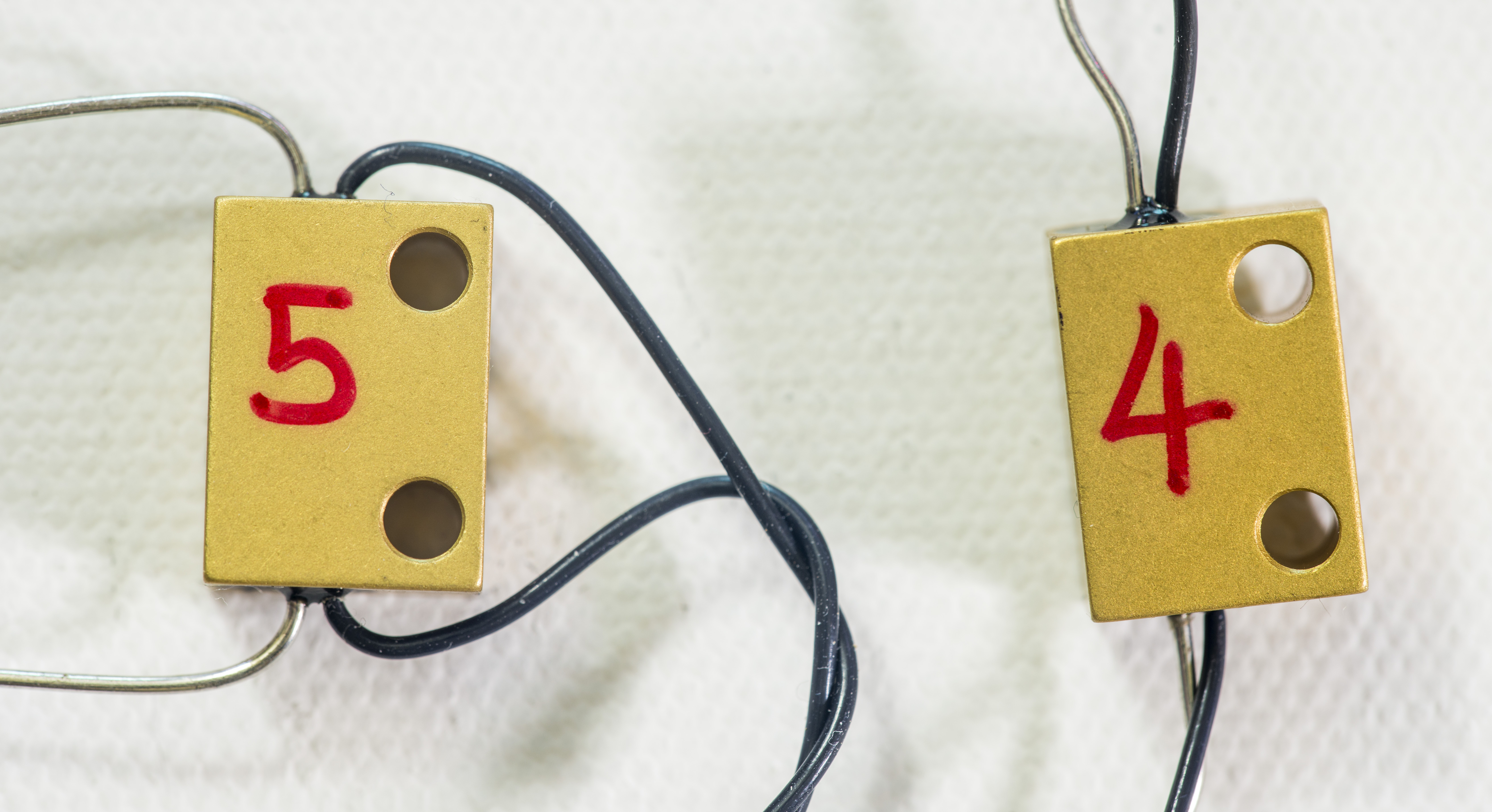 |
| PRC HR3716N from MC-7 set | 10 KΩ | 2002-4 | +6.67 ppm/K |  |
| Wirewound VWW 0.05% | 100 Ω | 2002-4 | +3.0…+7.5 ppm/K | 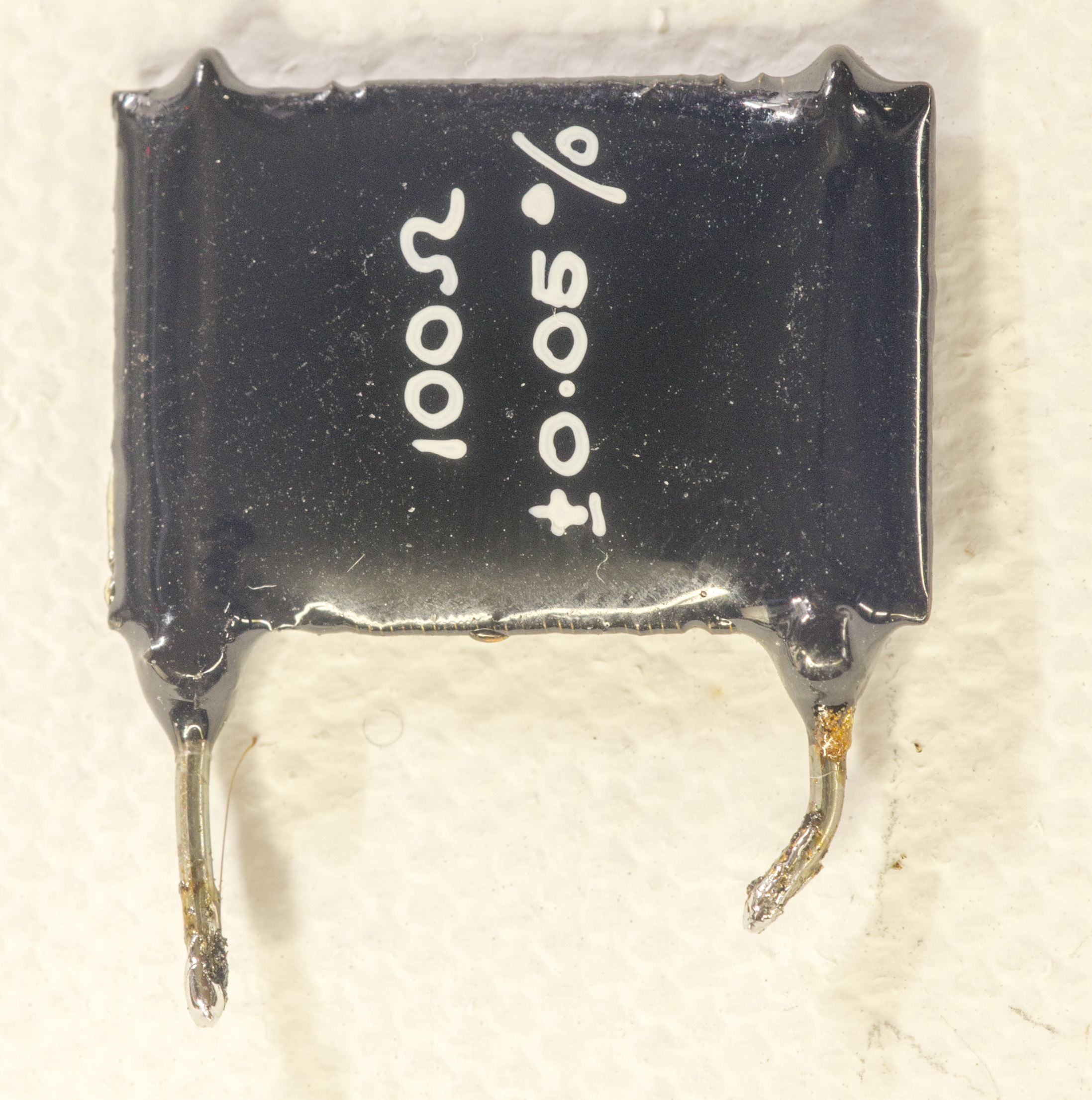 |
| Old black VWW 0.1% | 1.5 KΩ | 2002-4 | +8 ppm/K | 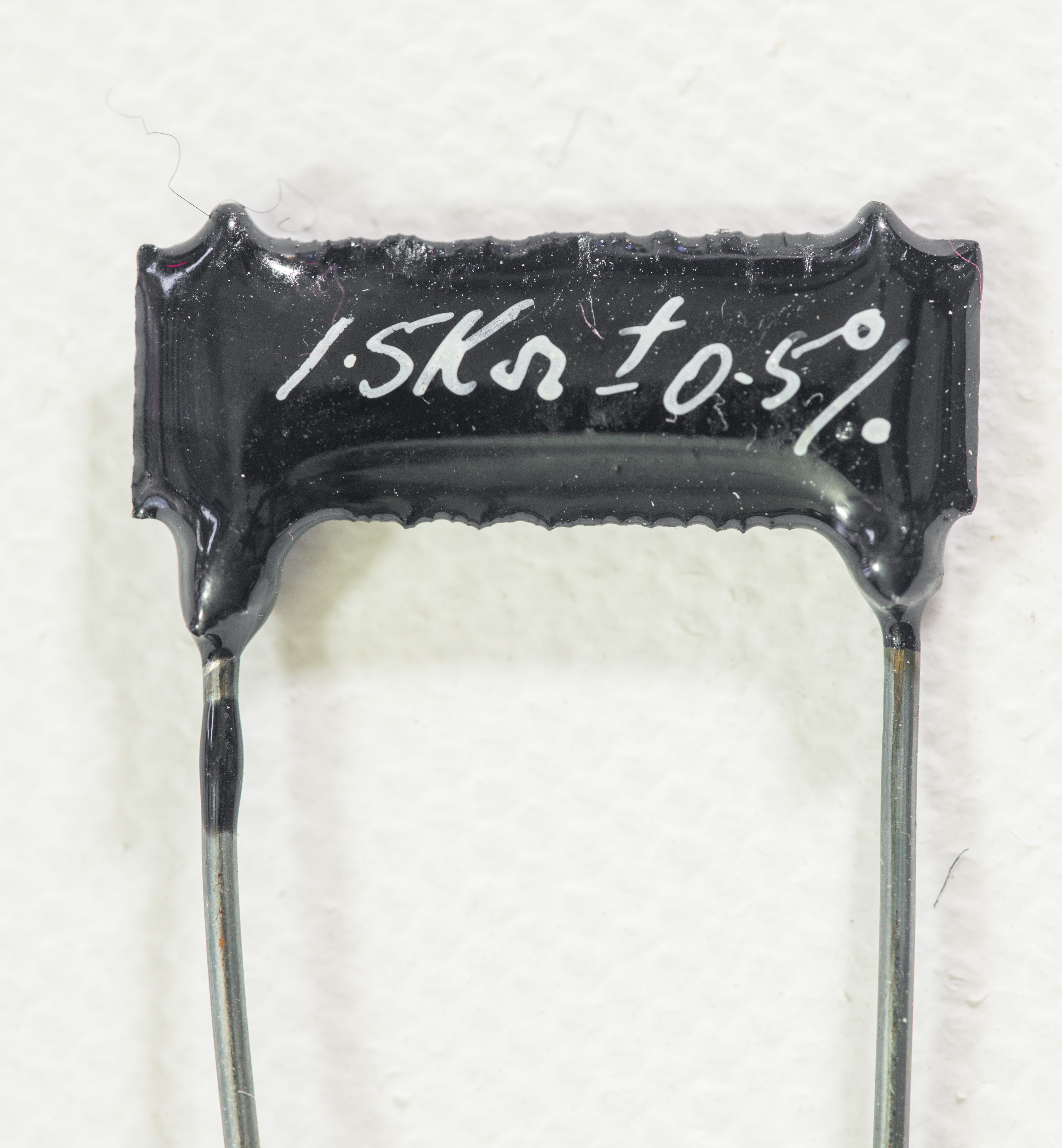 |
| Old black VWW 0.05% | 353 Ω | 2002-6 | +8 ppm/K | 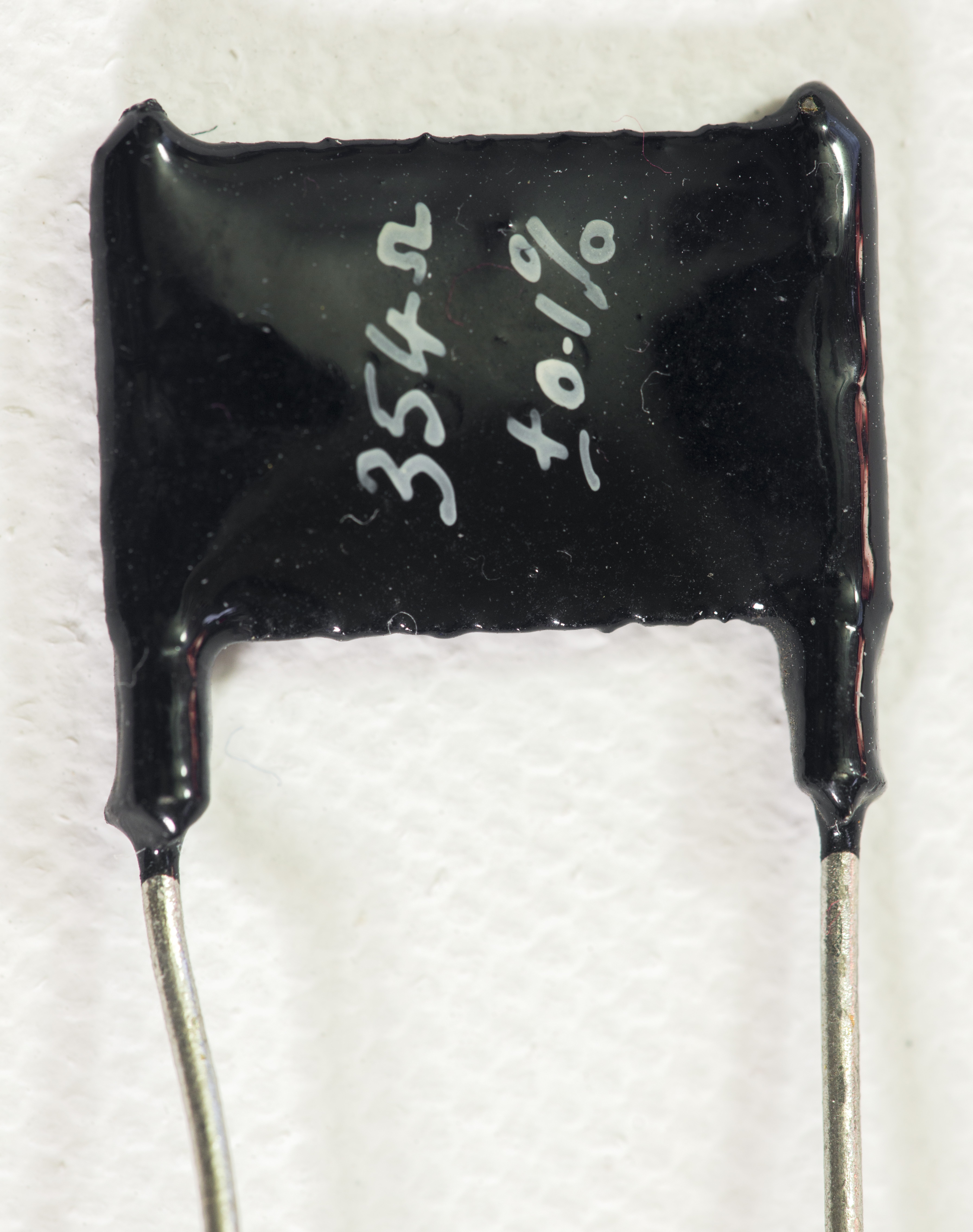 |
| HP 3458A shunt | 1 Ω | 2002-4 | +8.3 ppm/K | |
| VPG VPR5 #2 from eBay | 1 Ω | 3458A | +10 ppm/K | 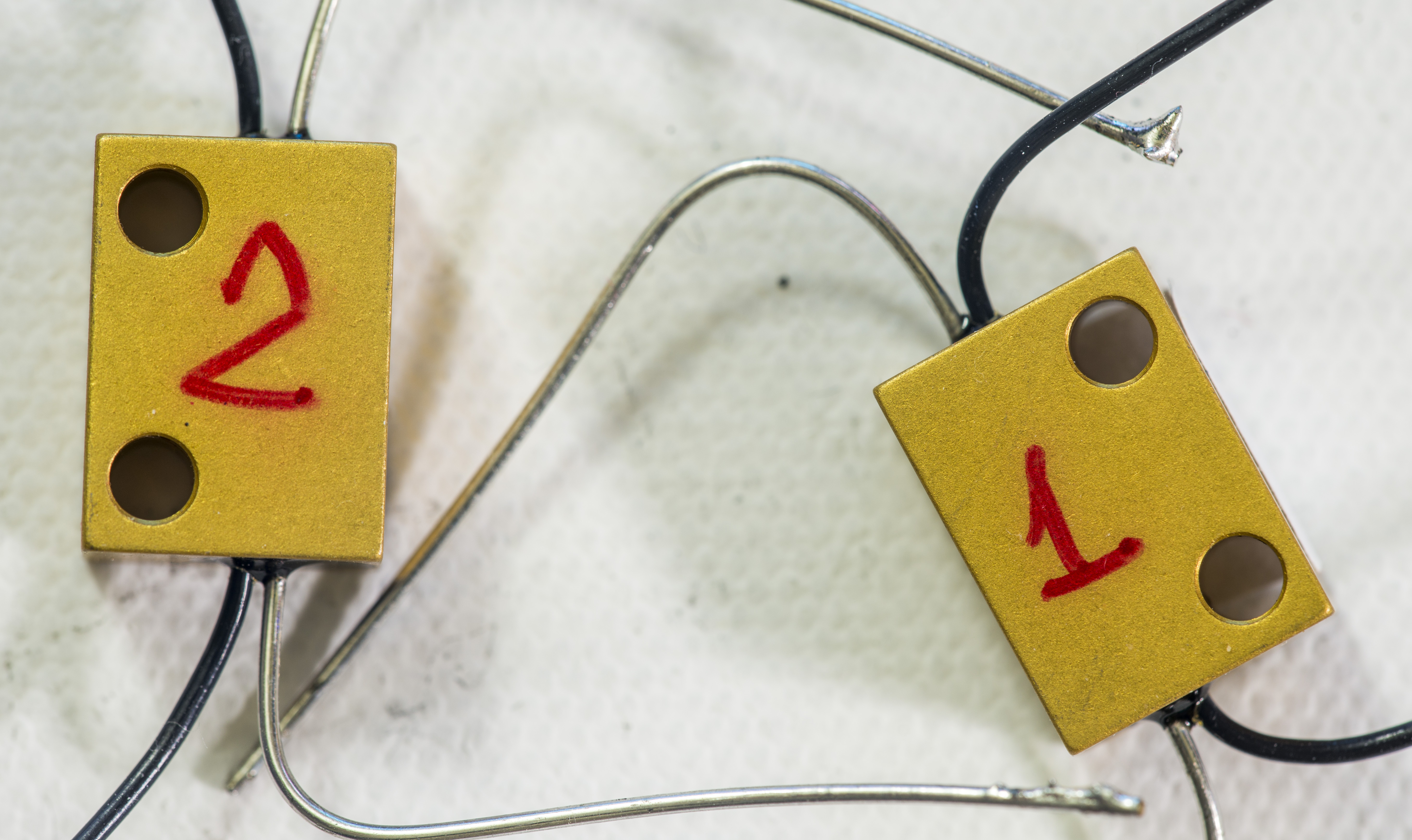 |
| VPG VPR5 #4 from eBay | 1 Ω | 2002-6 | +10 ppm/K | |
| PRC 10 ohm | 10 Ω | 2002-4 | +14.6 ppm/K | |
| VPG VPR5 1R 0# | 1 Ω | 3458B | +15 ppm/K | 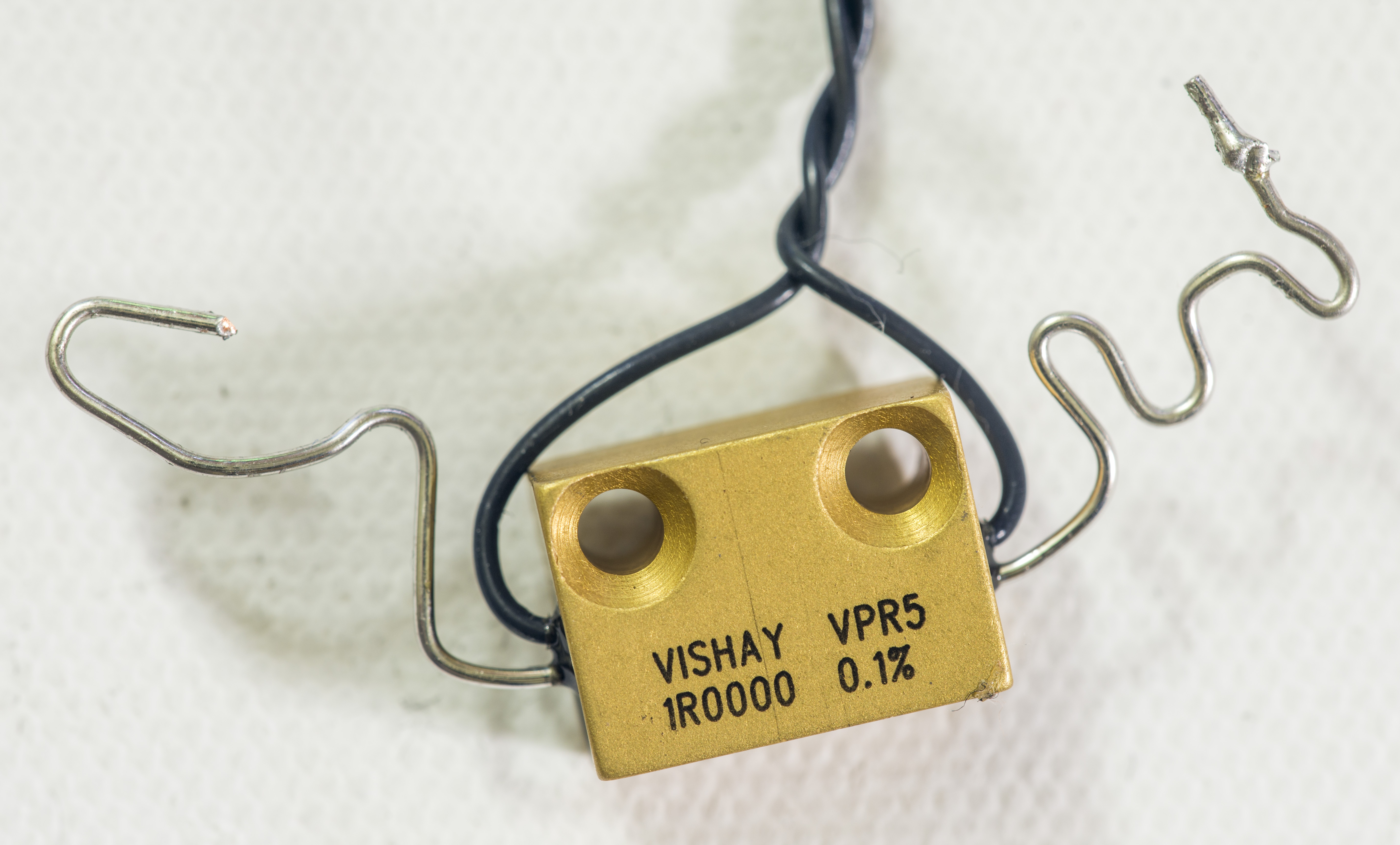  |
| VPG VPR5 #1 from eBay | 1 Ω | 3458A | +16.5 ppm/K | |


Brand new VPG BMF batch test 2018
| VPG VHP103ZT #1 | 40 KΩ | 6581T | +1.06 ppm/K | |
| VPG VHP103ZT #2 | 40 KΩ | 3458A | +0.63 ppm/K | |
| VPG VHP103ZT #3 | 4.53 KΩ | 2002-6 | -0.09 ppm/K | |
| VPG VHP103ZT #4 | 4.53 KΩ | 3458A | +0.63 ppm/K | |
| VPG VHP103ZT #5 | 3 KΩ | 6581T | -0.39 ppm/K | |
| VPG VHP103ZT #6 | 3 KΩ | 2002-6 | -0.39 ppm/K | |
| VPG VHP103ZT #7 | 300 Ω | 3458A | -0.25 ppm/K | |
| VPG VHD200T #8 | 1 KΩ | 3458B | +0.28 ppm/K | |
| 13 KΩ | 2002-6 | -0.02 ppm/K | ||
| VPG VHP103T #9 | 300 Ω | 3458A | -0.23 ppm/K | |
| VPG VHD200T #10 | 1 KΩ | 3458B | -0.54 ppm/K | |
| 13 KΩ | 2002-6 | -0.59 ppm/K | ||
| VPG VHP203T #11 D865 | 120 Ω | 3458A | +0.28 ppm/K | |
| VPG VHD203T #12 D859 | 120 Ω | 3458B | -0.66 ppm/K | |
| VPG VHD203T #13 D861 | 120 Ω | 2002-6 | -0.66 ppm/K | |
| VPG VHP203T #14 Dxxx | 120 Ω | 3458A | -0.19 ppm/K | |
| VPG VHD203T #15 Dxxx | 120 Ω | 3458B | +0.38 ppm/K | |
| VPG VHD203T #16 Dxxx | 120 Ω | 2002-6 | -0.19 ppm/K | |
| VPG S102KT #17 | 70 KΩ | 3458A | +0.7 ppm/K | |
| VPG S102KT #18 | 70 KΩ | 3458B | +0.3 ppm/K | |
| VPG VHD203T #19 Dxxx | 120 Ω | 2002-6 | +0.25 ppm/K | |
| VPG VHD200T #20 | 1 KΩ | 3458A | -0.47 ppm/K | |
| 13 KΩ | 3458B | -0.38 ppm/K | ||
| VPG VHP203T #21 | 120 Ω | 2002-6 | -0.31 ppm/K | |
| VPG VHD200T #22 | 1 KΩ | 3458A | -0.63 ppm/K | |
| 13 KΩ | 3458B | -0.66 ppm/K | ||
| VPG VHP203T #23 | 120 Ω | 2002-6 | -0.41 ppm/K | |
| VPG VHD200T #24 | 1 KΩ | 3458A | -0.84 ppm/K | |
| 13 KΩ | 3458B | -0.97 ppm/K | ||
| VPG VHP203T #25 | 120 Ω | 2002-6 | -0.19 ppm/K | |
| VPG VHD200T #26 | 1 KΩ | 3458A | -0.71 ppm/K | |
| 13 KΩ | 3458B | -0.72 ppm/K | ||
| VPG VHP203T #27 | 120 Ω | 2002-6 | -0.34 ppm/K | |
| VPG VHD200T #28 | 1 KΩ | 3458A | -0.34 ppm/K | |
| 13 KΩ | 3458B | -0.94 ppm/K | ||
| VPG VHP203ZT #29 | 120 Ω | 2002-6 | -0.78 ppm/K | |
| VPG S102KT #30 | 70 KΩ | 3458A | -0.3 ppm/K | |
| VPG S102KT #31 | 70 KΩ | 3458B | +0.3 ppm/K | |
| VPG S102KT #32 | 70 KΩ | 2002-6 | +0.4 ppm/K | |
| VPG S102KT #33 | 70 KΩ | 3458A | +0.5 ppm/K | |
| VPG S102KT #34 | 70 KΩ | 3458B | +0.3 ppm/K | |
| VPG S102KT #35 | 70 KΩ | 2002-6 | -1.1 ppm/K | |
| VPG S102KT #36 | 70 KΩ | 3458A | +0.3 ppm/K | |
| VPG S102KT #37 | 70 KΩ | 3458B | +0.5 ppm/K | |
| VPG S102KT #38 | 70 KΩ | 2002-6 | +0.7 ppm/K | |
| VPG S102KT #39 | 70 KΩ | 3458A | -0.3 ppm/K | |
| VPG S102KT #40 | 70 KΩ | 3458B | +0.4 ppm/K | |
| VPG S102KT #41 | 70 KΩ | 2002-6 | -0.9 ppm/K | |
| VPG S102KT #42 | 70 KΩ | 3458A | +0.4 ppm/K | |
| VPG S102KT #43 | 70 KΩ | 3458B | +0.3 ppm/K | |
| VPG S102KT #44 | 70 KΩ | 2002-6 | +0.3 ppm/K | |
| VPG S102KT #45 | 70 KΩ | 3458A | -0.9 ppm/K | |
| VPG S102KT #46 | 70 KΩ | 3458B | +0.6 ppm/K | |
| VPG S102KT #47 | 70 KΩ | 2002-6 | +0.4 ppm/K | |
| VPG VHP203T #48 | 120 Ω | 3458A | -0.28 ppm/K | |
| VPG VHD200T #49 | 1 KΩ | 3458B | -0.93 ppm/K | |
| 13 KΩ | 2002-6 | -0.28 ppm/K | ||
| Pipelie’s 10K DIY (4×40K VHP in metal box | 10 KΩ | 3458A | <0.05 ppm/K | |
| VPG VHP203T #50 | 120 Ω | 3458B | +0.13 ppm/K | |
| VPG VHP203T #51 | 120 Ω | 2002-6 | -0.72 ppm/K | |
| VPG VHD200T #52 | 1 KΩ | 3458A | -0.17 ppm/K | |
| 13 KΩ | 2002-6 | -0.05 ppm/K | ||
| VPG S102KT #53 | 70 KΩ | 3458B | +1.1 ppm/K | |
| VPG VHP203T #54 | 120 Ω | 2002-6 | -0.62 ppm/K | |
| VPG VLR #55 | 1 Ω 4W | 3458A | -0.4 ppm/K | |
| VPG VLR #56, dmg | 1 Ω 4W | 3458B | -2.3 ppm/K | |
| VPG VHP203T #57 | 120 Ω | 2002-6 | -0.18 ppm/K | |
| VPG VHD200T #58 | 1 KΩ | 3458A | -1.18 ppm/K | |
| 13 KΩ | 2002-6 | -1.00 ppm/K | ||
| VPG VHP203T #59 | 120 Ω | 3458A | -0.55 ppm/K | |
| VPG VHD200T #60 | 1 KΩ | 3458B | -0.28 ppm/K | |
| 13 KΩ | 2002-6 | -0.28 ppm/K | ||
| VPG VHP203T #61 | 120 Ω | 2002-4 | -0.34 ppm/K | |
| VPG VHP203T #62 | 120 Ω | 3458A | +0.22 ppm/K | |
| VPG VHP203T #63 | 120 Ω | 2002-4 | -0.84 ppm/K | |
| VPG VHP203T #64 | 120 Ω | 3458B | -0.06 ppm/K | |
| VPG VHP203T #66 | 120 Ω | 2002-4 | -0.81 ppm/K | |
| VPG VHD200T #65 | 1 KΩ | 2002-4 | -0.5 ppm/K | |
| 13 KΩ | 8508A | -0.65 ppm/K | ||
| VPG VHD200T #69 | 1 KΩ | 3458A | -0.54 ppm/K | |
| 13 KΩ | 2002-6 | -0.66 ppm/K | ||
| VPG S102KT #68 | 70 KΩ | 3458B | +0.98 ppm/K | |
| VPG VHD200T #72 | 1 KΩ | 8508A | -0.66 ppm/K | |
| 13 KΩ | 2002-4 | -0.90 ppm/K | ||
| VPG VHP203T #70 | 120 Ω | 3458B | -0.53 ppm/K | |
| VPG VHD200T #71 | 1 KΩ | 8508A | -0.66 ppm/K | |
| 13 KΩ | 2002-4 | -0.90 ppm/K | ||
| VPG S102KT #73 | 70 KΩ | 3458B | -1.0 ppm/K | |
| VPG VHD200T #74 | 1 KΩ | 3458A | -0.68 ppm/K | |
| 13 KΩ | 2002-6 | -0.59 ppm/K | ||
| VPG VHD200T #75 | 1 KΩ | 8508A | -0.41 ppm/K | |
| 13 KΩ | 2002-4 | -1.09 ppm/K | ||
| VPG S102KT #76 | 70 KΩ | 3458B | +0.6 ppm/K | |
| VPG VHD200T #77 | 1 KΩ | 3458A | -0.3 ppm/K | |
| 13 KΩ | 2002-6 | -0.1 ppm/K | ||
| VPG VHD200T #78 | 1 KΩ | 8508A | -0.54 ppm/K | |
| 13 KΩ | 2002-4 | -0.50 ppm/K | ||
| VPG S102KT #79 | 70 KΩ | 3458B | -0.5 ppm/K | |
| VPG VHD200T #80 | 1 KΩ | 3458A | -0.58 ppm/K | |
| 13 KΩ | 2002-6 | -0.87 ppm/K | ||
| VPG VHD200T #81 | 1 KΩ | 8508A | -0.68 ppm/K | |
| 13 KΩ | 2002-4 | -0.84 ppm/K | ||
| VPG VHA518-11 Custom | 1 MΩ | 8508A | -0.10 ppm/K | |
| VPG VHD200T #82 | 1 KΩ | 3458A | -0.41 ppm/K | |
| 13 KΩ | 2002-6 | -0.19 ppm/K | ||
| VPG VHD200T #83 | 1 KΩ | 8508A | -0.22 ppm/K | |
| 13 KΩ | 2002-4 | -0.56 ppm/K | ||
| VPG VHA518-11 Custom | 1 MΩ | 8508A | -0.12 ppm/K | |
| VPG VHD200T #84 | 1 KΩ | 3458A | -0.47 ppm/K | |
| 13 KΩ | 2002-6 | -0.78 ppm/K | ||
| VPG VHD200T #85 | 1 KΩ | 8508A | -0.28 ppm/K | |
| 13 KΩ | 2002-4 | -0.22 ppm/K |
And now same data, sorted by resistance temperature coefficient, and per resistor type.
| VHD200T #49 P.65 | 1 KΩ | 3458B | -0.93 ppm/K | VHP203T #15 Dxxx | 120 Ω | 3458B | +0.3 ppm/K | S102KT #53 | 70 KΩ | 3458B | +1.1 ppm/K | |||
| 13 KΩ | 2002-6 | -0.28 ppm/K | ||||||||||||
| VHD200T #58 P.18 | 1 KΩ | 3458A | -1.18 ppm/K | VHP203T #11 D865 | 120 Ω | 3458A | +0.28 ppm/K | S102KT #68 | 70 KΩ | 3458B | +1.0 ppm/K | |||
| 13 KΩ | 2002-6 | -1.00 ppm/K | ||||||||||||
| VHD200T #53 P.12 | 1 KΩ | 3458A | -0.17 ppm/K | VHP203T #19 Dxxx | 120 Ω | 2002-6 | +0.25 ppm/K | S102KT #17 | 70 KΩ | 3458A | +0.7 ppm/K | |||
| 13 KΩ | 2002-6 | -0.05 ppm/K | ||||||||||||
| VHD200T #74 P.09 | 1 KΩ | 3458A | -0.68 ppm/K | VHP203T #62 Dxxx | 120 Ω | 3458A | +0.22 ppm/K | S102KT #38 | 70 KΩ | 2002-6 | +0.7 ppm/K | |||
| 13 KΩ | 2002-6 | -0.59 ppm/K | ||||||||||||
| VHD200T #20 P.09 | 1 KΩ | 3458A | -0.47 ppm/K | VHP203T #50 Dxxx | 120 Ω | 3458B | +0.13 ppm/K | S102KT #46 | 70 KΩ | 3458B | +0.6 ppm/K | |||
| 13 KΩ | 3458B | -0.38 ppm/K | ||||||||||||
| VHD200T #60 0.0 | 1 KΩ | 3458B | -0.28 ppm/K | VHP203T #64 Dxxx | 120 Ω | 3458B | -0.06 ppm/K | S102KT #76 | 70 KΩ | 3458B | +0.6 ppm/K | |||
| 13 KΩ | 2002-6 | -0.28 ppm/K | ||||||||||||
| VHD200T #26 N.01 | 1 KΩ | 3458A | -0.71 ppm/K | VHP203T #57 Dxxx | 120 Ω | 2002-6 | -0.18 ppm/K | S102KT #33 | 70 KΩ | 3458A | +0.5 ppm/K | |||
| 13 KΩ | 3458B | -0.72 ppm/K | ||||||||||||
| VHD200T #22 N.03 | 1 KΩ | 3458A | -0.63 ppm/K | VHP203T #14 Dxxx | 120 Ω | 3458A | -0.19 ppm/K | S102KT #37 | 70 KΩ | 3458B | +0.5 ppm/K | |||
| 13 KΩ | 3458B | -0.66 ppm/K | ||||||||||||
| VHD200T #78 N.04 | 1 KΩ | 8508A | -0.54 ppm/K | VHP203T #25 Dxxx | 120 Ω | 2002-6 | -0.19 ppm/K | S102KT #47 | 70 KΩ | 2002-6 | +0.4 ppm/K | |||
| 13 KΩ | 2002-4 | -0.50 ppm/K | ||||||||||||
| VHD200T #10 N.05 | 1 KΩ | 3458B | -0.54 ppm/K | VHP203T #16 Dxxx | 120 Ω | 2002-6 | -0.19 ppm/K | S102KT #32 | 70 KΩ | 2002-6 | +0.4 ppm/K | |||
| 13 KΩ | 2002-6 | -0.59 ppm/K | ||||||||||||
| VHD200T #85 N.06 | 1 KΩ | 8508A | -0.28 ppm/K | VHP203T #48 Dxxx | 120 Ω | 3458A | -0.28 ppm/K | S102KT #42 | 70 KΩ | 3458A | +0.4 ppm/K | |||
| 13 KΩ | 2002-4 | -0.22 ppm/K | ||||||||||||
| VHD200T #24 N.13 | 1 KΩ | 3458A | -0.84 ppm/K | VHP203T #21 Dxxx | 120 Ω | 2002-6 | -0.3 ppm/K | S102KT #40 | 70 KΩ | 3458B | +0.4 ppm/K | |||
| 13 KΩ | 3458B | -0.97 ppm/K | ||||||||||||
| VHD200T #65 N.15 | 1 KΩ | 2002-4 | -0.50 ppm/K | VHP203T #27 Dxxx | 120 Ω | 2002-6 | -0.3 ppm/K | S102KT #43 | 70 KΩ | 3458B | +0.3 ppm/K | |||
| 13 KΩ | 8508A | -0.65 ppm/K | ||||||||||||
| VHD200T #81 N.16 | 1 KΩ | 8508A | -0.68 ppm/K | VHP203T #61 Dxxx | 120 Ω | 2002-4 | -0.3 ppm/K | S102KT #44 | 70 KΩ | 2002-6 | +0.3 ppm/K | |||
| 13 KΩ | 2002-4 | -0.84 ppm/K | ||||||||||||
| VHD200T #71 N.19 | 1 KΩ | 3458A | -0.68 ppm/K | VHP203T #23 Dxxx | 120 Ω | 2002-6 | -0.4 ppm/K | S102KT #18 | 70 KΩ | 3458B | +0.3 ppm/K | |||
| 13 KΩ | 2002-6 | -0.87 ppm/K | ||||||||||||
| VHD200T #72 N.24 | 1 KΩ | 8508A | -0.66 ppm/K | VHP203T #70 Dxxx | 120 Ω | 3458B | -0.5 ppm/K | S102KT #31 | 70 KΩ | 3458B | +0.3 ppm/K | |||
| 13 KΩ | 2002-4 | -0.90 ppm/K | ||||||||||||
| VHD200T #80 N.29 | 1 KΩ | 3458A | -0.58 ppm/K | VHP203T #59 Dxxx | 120 Ω | 3458A | -0.5 ppm/K | S102KT #34 | 70 KΩ | 3458B | +0.3 ppm/K | |||
| 13 KΩ | 2002-6 | -0.87 ppm/K | ||||||||||||
| VHD200T #8 N.3 | 1 KΩ | 3458B | +0.28 ppm/K | VHP203T #54 Dxxx | 120 Ω | 2002-6 | -0.6 ppm/K | S102KT #36 | 70 KΩ | 3458A | +0.3 ppm/K | |||
| 13 KΩ | 2002-6 | -0.02 ppm/K | ||||||||||||
| VHD200T #82 N.22 | 1 KΩ | 3458A | -0.41 ppm/K | VHP203T #12 D859 | 120 Ω | 3458B | -0.6 ppm/K | S102KT #30 | 70 KΩ | 3458A | -0.3 ppm/K | |||
| 13 KΩ | 2002-6 | -0.19 ppm/K | ||||||||||||
| VHD200T #83 N.37 | 1 KΩ | 8508A | -0.22 ppm/K | VHP203T #13 D861 | 120 Ω | 2002-6 | -0.6 ppm/K | S102KT #39 | 70 KΩ | 3458A | -0.3 ppm/K | |||
| 13 KΩ | 2002-4 | -0.56 ppm/K | ||||||||||||
| VHD200T #77 N.2 | 1 KΩ | 3458A | -0.3 ppm/K | VHP203T #51 Dxxx | 120 Ω | 2002-6 | -0.7 ppm/K | S102KT #79 | 70 KΩ | 3458B | -0.5 ppm/K | |||
| 13 KΩ | 2002-6 | -0.1 ppm/K | ||||||||||||
| VHD200T #84 N.31 | 1 KΩ | 3458A | -0.47 ppm/K | VHP203T #67 Dxxx | 120 Ω | 8508A | -0.7 ppm/K | S102KT #41 | 70 KΩ | 2002-6 | -0.9 ppm/K | |||
| 13 KΩ | 2002-6 | -0.78 ppm/K | ||||||||||||
| VHD200T #28 N.6 | 1 KΩ | 3458A | -0.34 ppm/K | VHP203T #29 Dxxx | 120 Ω | 2002-6 | -0.7 ppm/K | S102KT #45 | 70 KΩ | 3458A | -0.9 ppm/K | |||
| 13 KΩ | 3458B | -0.94 ppm/K | ||||||||||||
| VHD200T #75 N.68 | 1 KΩ | 8508A | -0.41 ppm/K | VHP203T #66 Dxxx | 120 Ω | 2002-4 | -0.8 ppm/K | S102KT #73 | 70 KΩ | 3458B | -1.0 ppm/K | |||
| 13 KΩ | 2002-4 | -1.09 ppm/K | ||||||||||||
| VHD200T #69 | 1 KΩ | 3458A | -0.54 ppm/K | VHP203T #63 Dxxx | 120 Ω | 2002-4 | -0.8 ppm/K | S102KT #35 | 70 KΩ | 2002-6 | -1.1 ppm/K | |||
| 13 KΩ | 2002-6 | -0.66 ppm/K |
Scanner setup
To further improve testing speed by paralleling multiple resistors test at one temperature ramp, Keithley 7168 nanovolt scanner was used.
Results from scanner setup
Separate table with results obtained from more complex scanner setup presented below.
| Resistor | Value | Channel | Test current | Result | Sample photo |
|---|---|---|---|---|---|
| 3458AR HP 03458-82501-1 shunt 4W | 0.1 Ω | 2002-6 | 7.2mA direct | -6.2…-13 ppm/K | |
| 3458AR HP 03458-82501-1 shunt 4W | 0.1 Ω | 182M | 1000mA K2304A | +7.5 ppm/K 25C to 35C | |
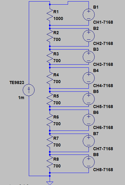
| PRC 1 ohm | 1 Ω | 182M | 100mA TE9823 | +54.6 ppm/K 100mA TE9823 |
| Resistor | Value | Channel | Test current | Result | Sample photo |
|---|---|---|---|---|---|
| AE | 1KΩ (999.95020) | 7168-1 | 1 mA TE9823 OC | -2.39 ppm/K | |
| VPG S102 #1 0.1% | 700 Ω (699.96084) | 7168-2 | 1 mA TE9823 OC | -1.64 ppm/K | |
| VPG S102 #2 0.1% | 700 Ω (699.96629) | 7168-3 | 1 mA TE9823 OC | -1.13 ppm/K | |
| VPG S102 #3 0.1% | 700 Ω (699.99800) | 7168-4 | 1 mA TE9823 OC | -2.45 ppm/K | |
| VPG S102 #4 0.1% | 700 Ω (699.94275) | 7168-5 | 1 mA TE9823 OC | -1.06 ppm/K | |
| VPG S102 #5 0.1% | 700 Ω (699.91479) | 7168-6 | 1 mA TE9823 OC | -1.63 ppm/K | |
| VPG S102 #6 0.1% | 700 Ω (699.93719) | 7168-7 | 1 mA TE9823 OC | -1.87 ppm/K | |
| VPG S102 #7 0.1% | 700 Ω (699.96841) | 7168-8 | 1 mA TE9823 OC | -1.38 ppm/K | |
| VPG VHP102L B9143 0.05% | 40 KΩ (39998.160) | 2002-4 | internal | +0.78 ppm/K | |
| VPG VHP102L B9143 0.05% | 40 KΩ (39998.007) | 2002-6 | internal | +0.60 ppm/K |
| Resistor | Value | Channel | Test current | Result | Sample photo |
|---|---|---|---|---|---|
| VPG VHD100 B9318 315709 #1 ×8320 | 7.663 KΩ | 7168-1 | 100 µA | -1.38 ppm/K | |
| VPG VHD100 B9318 315709 #2 ×8320 | 20 KΩ | 7168-2 | 100 µA | -0.96 ppm/K | |
| VPG VHD100 B9244 315709 #1 ×8318 | 7.663 KΩ | 7168-3 | 100 µA | -0.90 ppm/K | |
| VPG VHD100 B9244 315709 #2 ×8318 | 20 KΩ | 7168-4 | 100 µA | -0.86 ppm/K | |
| VPG VHD100 B9316 315709 #1 ×8342 | 7.663 KΩ | 7168-5 | 100 µA | -0.58 ppm/K | |
| VPG VHD100 B9316 315709 #2 ×8342 | 20 KΩ | 7168-6 | 100 µA | -0.54 ppm/K | |
| VPG VHD100 B9318 315709 #1 R0301 | 7.663 KΩ | 7168-7 | 100 µA | -0.86 ppm/K | |
| VPG VHD100 B9318 315709 #2 R0301 | 20 KΩ | 7168-8 | 100 µA | -0.75 ppm/K | |
| VPG S102 #1 0.1% | 75 KΩ | 2002-4 | internal | -1.31 ppm/K | |
| VPG S102 #2 0.1% | 75 KΩ | 2002-6 | internal | -0.55 ppm/K |
| Fluke teal WW | 540 Ω | 7168-1 | 3 mA/-3 mA | +1.8 ppm/K | |
| VPG S102 #1 0.1% | 330 Ω | 7168-2 | 3 mA/-3 mA | -1.65 ppm/K | |
| VPG S102 #2 0.1% | 330 Ω | 7168-3 | 3 mA/-3 mA | -1.4 ppm/K | |
| VPG S102 #1 0.1% | 10 Ω | 7168-4 | 3 mA/-3 mA | -0.375 ppm/K | |
| VPG S102 #1 0.1% | 178.1 Ω | 7168-5 | 3 mA/-3 mA | -1.03 ppm/K | |
| VPG S102 #1 0.1% | 522.2 Ω | 7168-6 | 3 mA/-3 mA | -1.23 ppm/K | |
| VPG S102 #2 0.1% | 522.2 Ω | 7168-7 | 3 mA/-3 mA | -0.305 ppm/K | |
| AE #3 0.1% | 522.2 Ω | 7168-8 | 3 mA/-3 mA | -1.95 ppm/K | |
| VPG S102 #1 0.1% | 40 KΩ | 2002-4 | Internal | -1.2 ppm/K | |
| VPG VHP102L B9117 | 7 KΩ | 2002-6 | Internal, OCOMP | -0.105 ppm/K |
| Resistor | Value | Channel | Test current | Result | Sample photo |
|---|---|---|---|---|---|
| VPG Divider #1 0.1% 1 | 10 KΩ | 7168-1 | 250 µA/-250 µA | bad data | |
| VPG Divider #1 0.1% 2 | 10 KΩ | 7168-2 | 250 µA/-250 µA | -0.65 ppm/K | |
| VPG Divider #2 0.1% 1 | 10 KΩ | 7168-3 | 250 µA/-250 µA | +1.15 ppm/K | |
| VPG Divider #2 0.1% 2 | 10 KΩ | 7168-4 | 250 µA/-250 µA | +1.2 ppm/K | |
| VPG S102 #1 1% | 5 KΩ | 7168-5 | 250 µA/-250 µA | -0.6 ppm/K | |
| VPG S102 #2 1% | 5 KΩ | 7168-6 | 250 µA/-250 µA | -1.45 ppm/K | |
| VPG S102 #3 1% | 5 KΩ | 7168-7 | 250 µA/-250 µA | -1.1 ppm/K | |
| VPG S102 #4 1% | 5 KΩ | 7168-8 | 250 µA/-250 µA | -0.73 ppm/K | |
| VPG S102 #2 0.1% | 40 KΩ | 2002-4 | Int. | -0.44 ppm/K | |
| VPG S102 #1 0.1% | 11.110 KΩ | 2002-6 | Int., OCOMP | +0.20 ppm/K |

| Resistor | Value | Channel | Test current | Result | Sample photo |
|---|---|---|---|---|---|
| Fluke WW | 5.496 Ω | 7168-1 | 2 mA/-2 mA | -4.3 ppm/K | |
| Fluke WW | 5.860 Ω | 7168-2 | 2 mA/-2 mA | -4.7 ppm/K | |
| Fluke WW | 5.894 Ω | 7168-3 | 2 mA/-2 mA | -7.5 ppm/K | |
| Fluke WW | 5.716 Ω | 7168-4 | 2 mA/-2 mA | -3.15 ppm/K | |
| VPG S102 #3 0.1% | 330 Ω | 7168-5 | 2 mA/-2 mA | -0.6 ppm/K | |
| VPG S102 #1 0.1% | 312.80 Ω | 7168-6 | 2 mA/-2 mA | -0.5 ppm/K | |
| VPG S102 #4 0.1% | 330 Ω | 7168-7 | 2 mA/-2 mA | -0.6 ppm/K | |
| VPG S102 #1 0.1% | 900 Ω | 7168-8 | 2 mA/-2 mA | -1.9 ppm/K | |
| VPG S102 #1 0.1% | 100 KΩ | 2002-6 | internal | -1.35 ppm/K | |
| AE #1 0.1% | 50 KΩ | 2002-4 | internal | +0.13 ppm/K |

Tests 2020
https://xdevs.com/doc/VPG/vhp2020/cm_front.jpg
https://xdevs.com/doc/VPG/vhp2020/cm_rear.jpg
https://xdevs.com/doc/VPG/vhp2020/tin_front.jpg
https://xdevs.com/doc/VPG/vhp2020/tin_rear.jpg
Overall results
Most of the Vishay Precision Group BMF resistors show almost linear negative temperature coefficient.
This study was a good introduction to resistor characterization, and we will be working to further improve accuracy, speed and test procedure for future temperature stability measurements. Stay tuned!
I would like to express my gratitude and appreciation to supporters of this project: Todd, pipelie and EEVBlog forums community and of course all our readers. Stay tuned, many more interesting things will be published soon.
Discussion about this article and related stuff is welcome in comment section or at our own IRC chat server: irc.xdevs.com (standard port 6667, channel: #xDevs.com). Web-interface for access mirrored on this page.
Projects like this are born from passion and a desire to share how things work. Education is the foundation of a healthy society - especially important in today's volatile world. xDevs began as a personal project notepad in Kherson, Ukraine back in 2008 and has grown with support of passionate readers just like you. There are no (and never will be) any ads, sponsors or shareholders behind xDevs.com, just a commitment to inspire and help learning. If you are in a position to help others like us, please consider supporting xDevs.com’s home-country Ukraine in its defense of freedom to speak, freedom to live in peace and freedom to choose their way. You can use official site to support Ukraine – United24 or Help99. Every cent counts.
Modified: Jan. 5, 2021, 6:39 a.m.