- Introduction
- Disclaimer
- Manuals and datasheets
- Exterior and overview
- Teardown and repair
- Test results
- Summary
Introduction
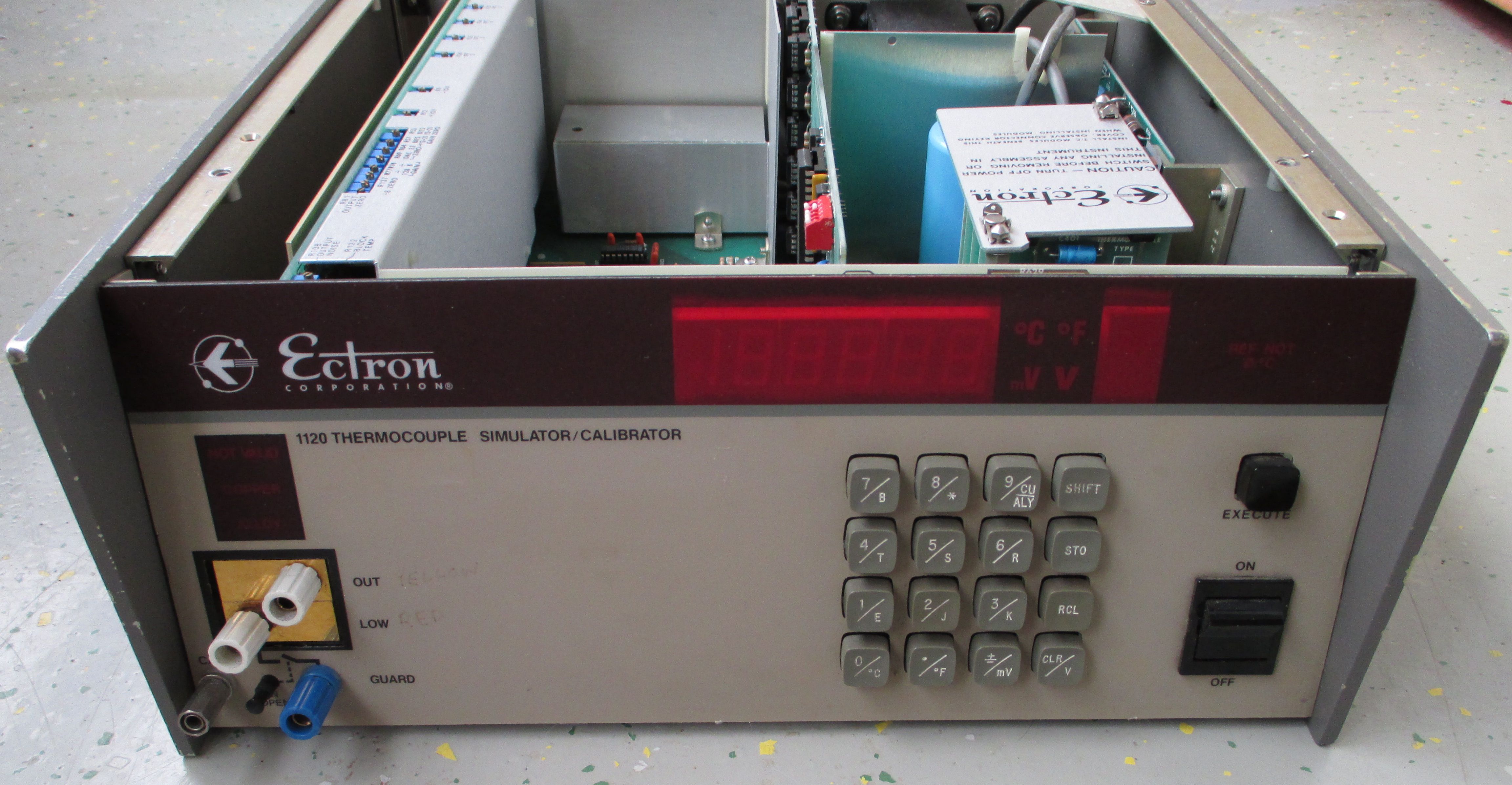
During my ebay-searches for interesting equipment I came across this interesting Ectron 1120 calibrator of which I couldn’t find teardown-pictures or any other notion online. Since its specs are quite good considering the price, I got one for ~50€ as broken from eBay. The Ectron 1120 Thermocouple-Simulator/Calibrator is capable of simulating standard thermocouples (Type E,J,K,T,R,S,B,C,N) with a high resolution of up to 0.0001 °C, as well as sourcing up to ±11 VDC at 100 µV resolution in the V range and 10 nV in the lower millivolt range. Low voltage capability easily beats general metrology purpose calibrators like Fluke 5700 series.
Lets take a look whats under the cover, attempt a repair and make a few measurements to see how good it really is. Due to being manufactured in the 80’s we have the luck of getting the manual copy for 1120 including schematics, maintenance and detailed theory of operation. :)
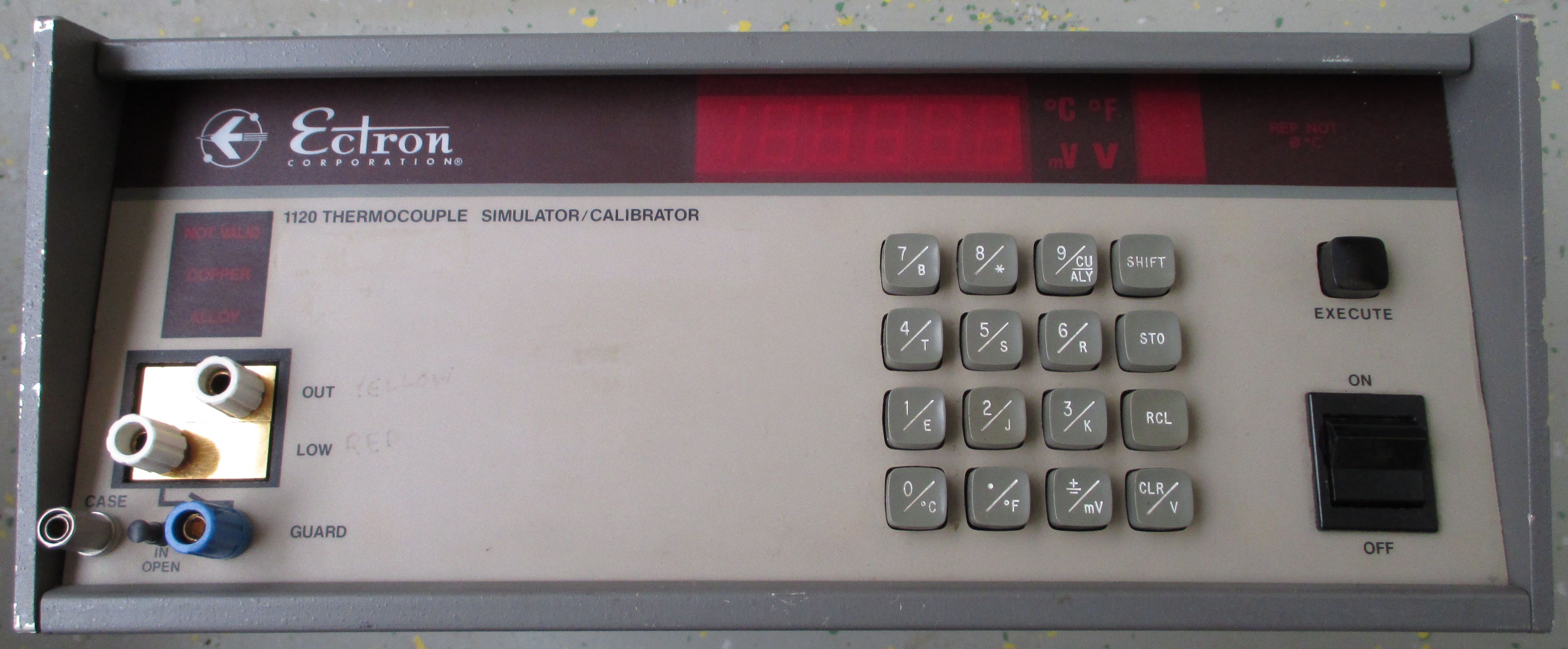
Image 1: Ectron 1120 thermocouple calibrator
Ectron today replaced this unit with modern sleek 1140A calibrator, but even the old 1120 is quite capable device.
Thermocouples are abbreviated as TC in the following article.
Disclaimer
Redistribution and use of this article, any parts of it or any images or files referenced in it, in source and binary forms, with or without modification, are permitted provided that the following conditions are met:
- Redistributions of article must retain the above copyright notice, this list of conditions, link to this page (https://xdevs.com/fix/ectron1120/) and the following disclaimer.
- Redistributions of files in binary form must reproduce the above copyright notice, this list of conditions, link to this page (https://xdevs.com/fix/ectron1120/), and the following disclaimer in the documentation and/or other materials provided with the distribution, for example Readme file.
All information posted here is hosted just for education purposes and provided AS IS. In no event shall the author, xDevs.com site, or any other 3rd party, including Ectron be liable for any special, direct, indirect, or consequential damages or any damages whatsoever resulting from loss of use, data or profits, whether in an action of contract, negligence or other tortuous action, arising out of or in connection with the use or performance of information published here.
If you willing to contribute or add your experience regarding instrument repairs or provide extra information, you can do so following these simple instructions
Manuals and datasheets
Ectron 1120 manual with service schematics
Ectron 1140A manual, no service information
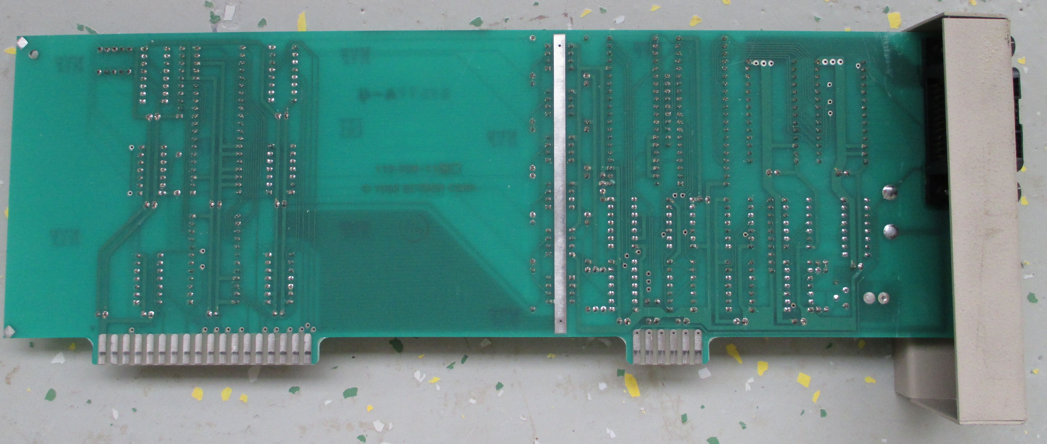
Exterior and overview
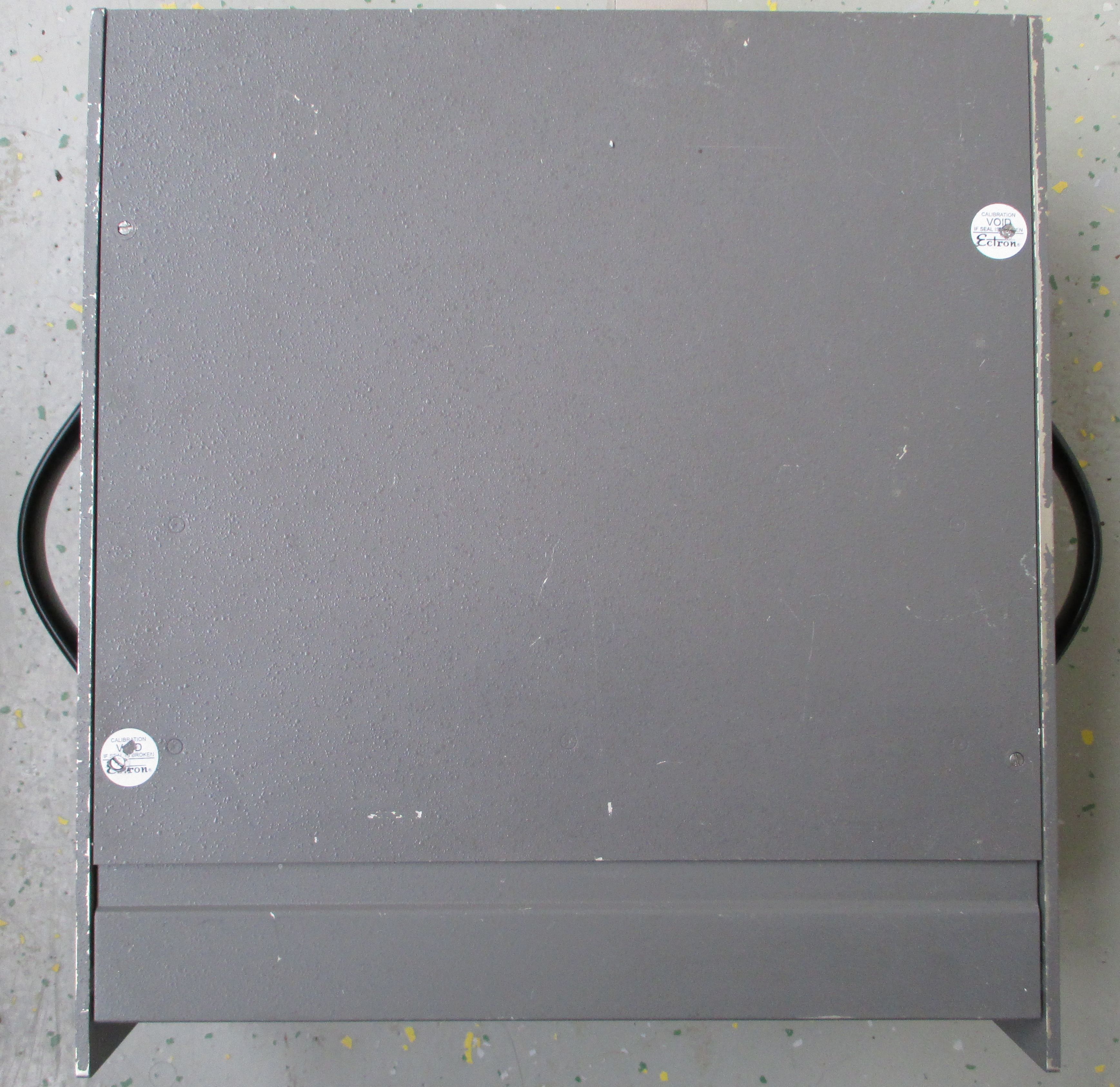

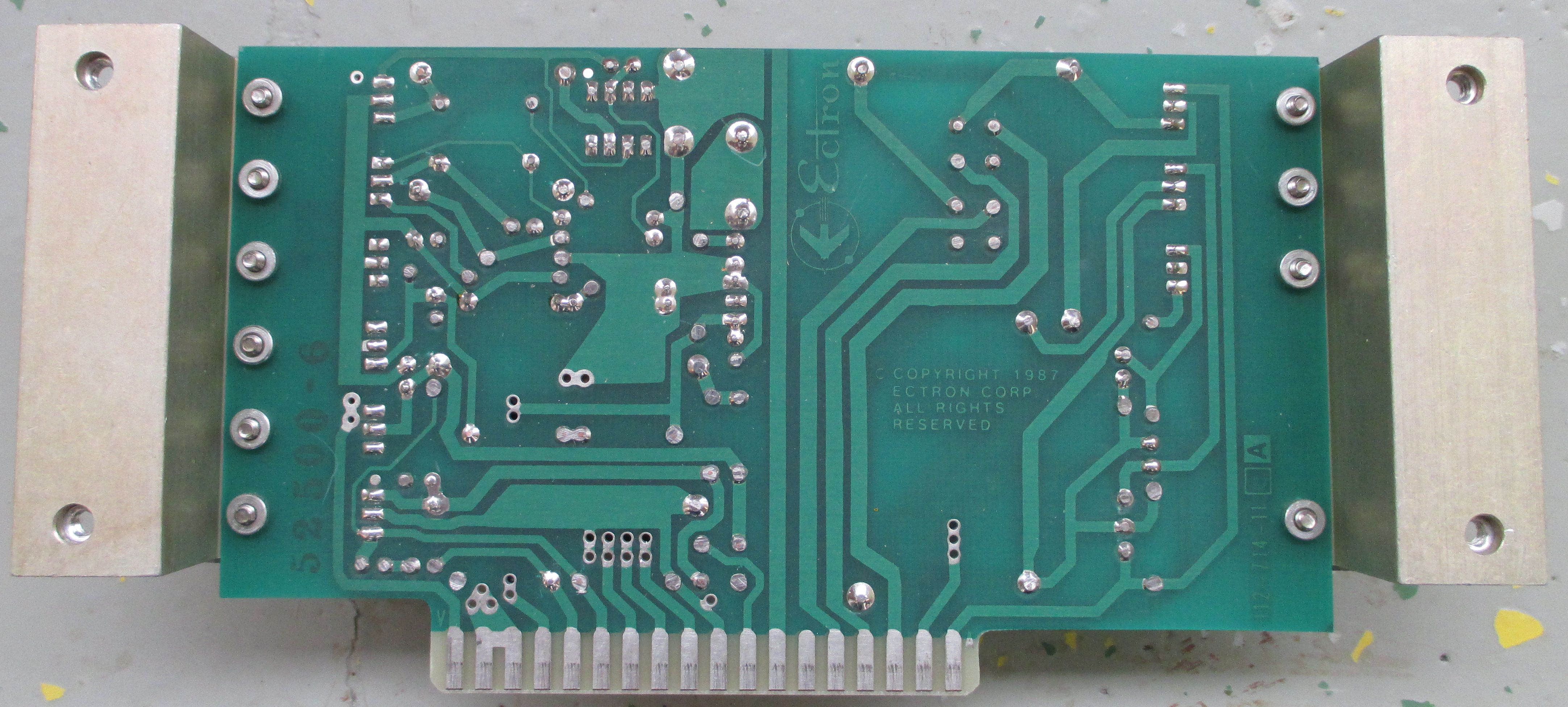
Image 2-3: Top and bottom chassis shields
Due to the well engineered thermally equalized copper block terminals for the outputs and its high-resolution DAC, accurate TC simulations are possible where other modern instruments like the Fluke 525A/B calibrator or the Fluke 7526A cannot provide the necessary resolution.
This is also interesting device to perform checks for nullmeters like the Keithley 155 or Fluke 845AB. The whole frame is very sturdy and nicely built.
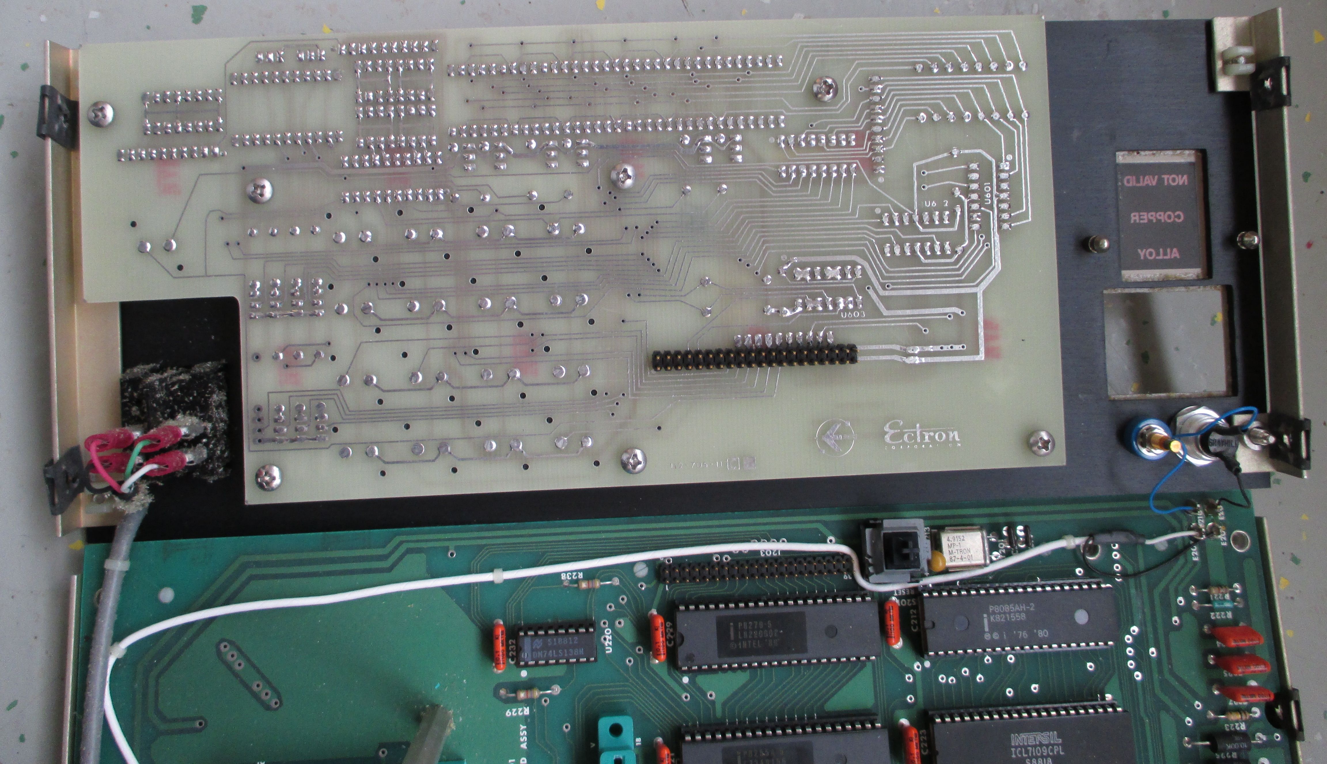
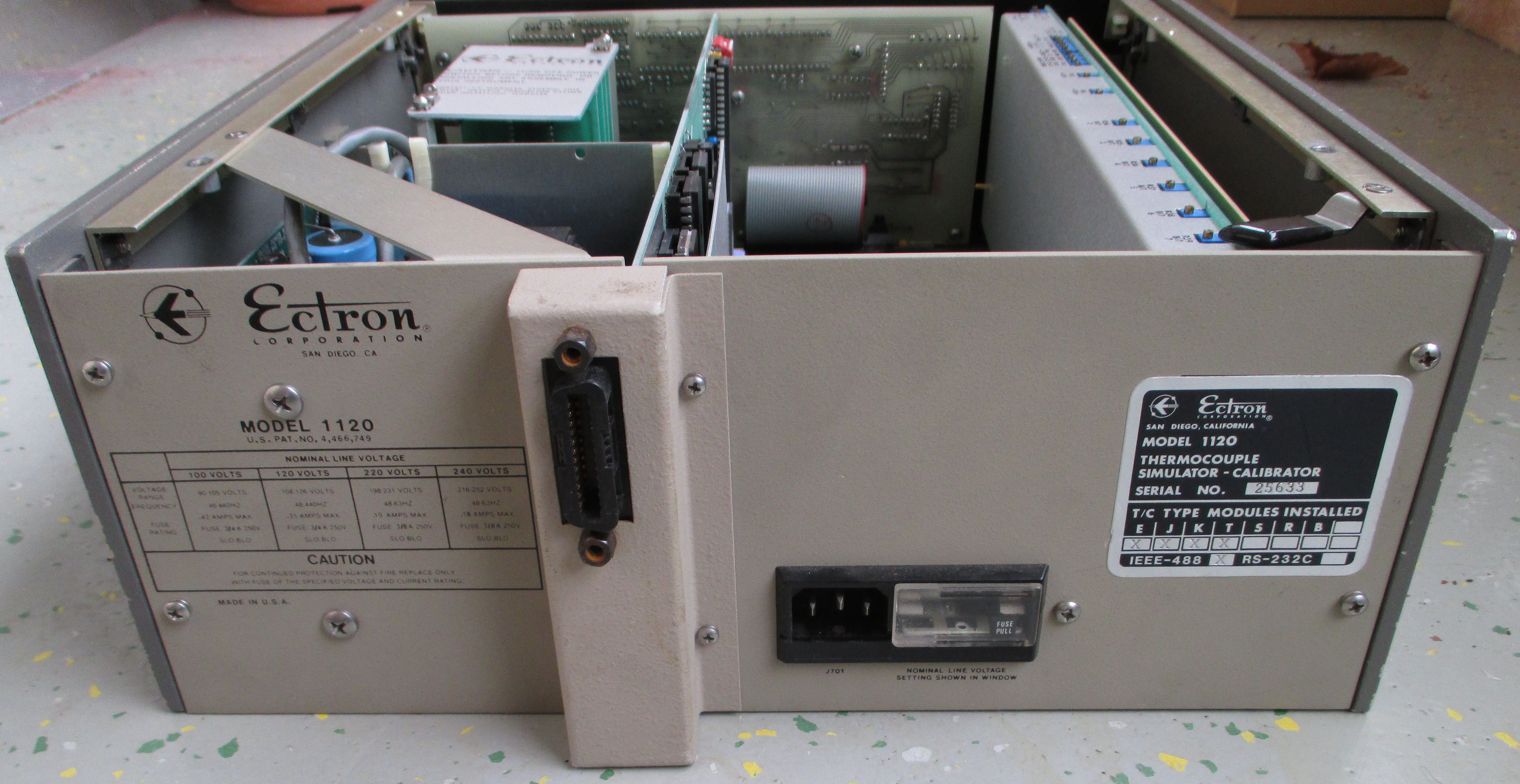
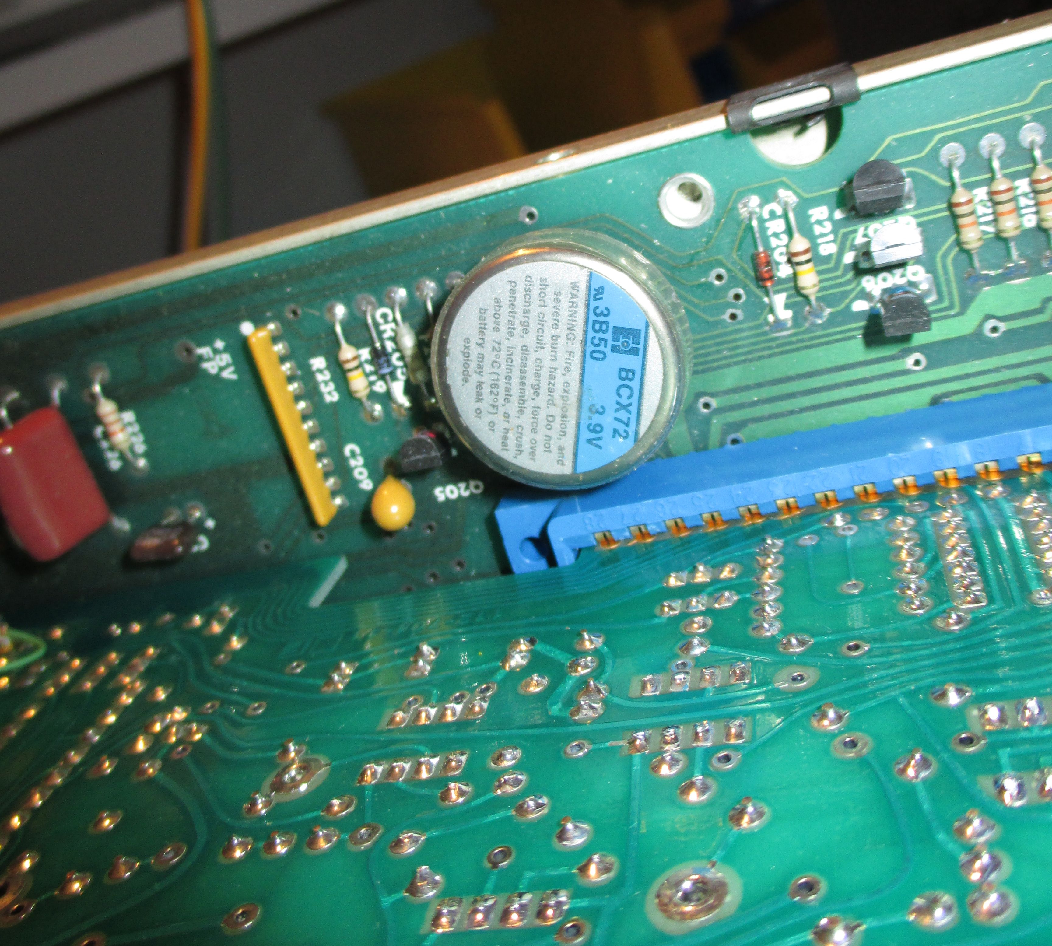
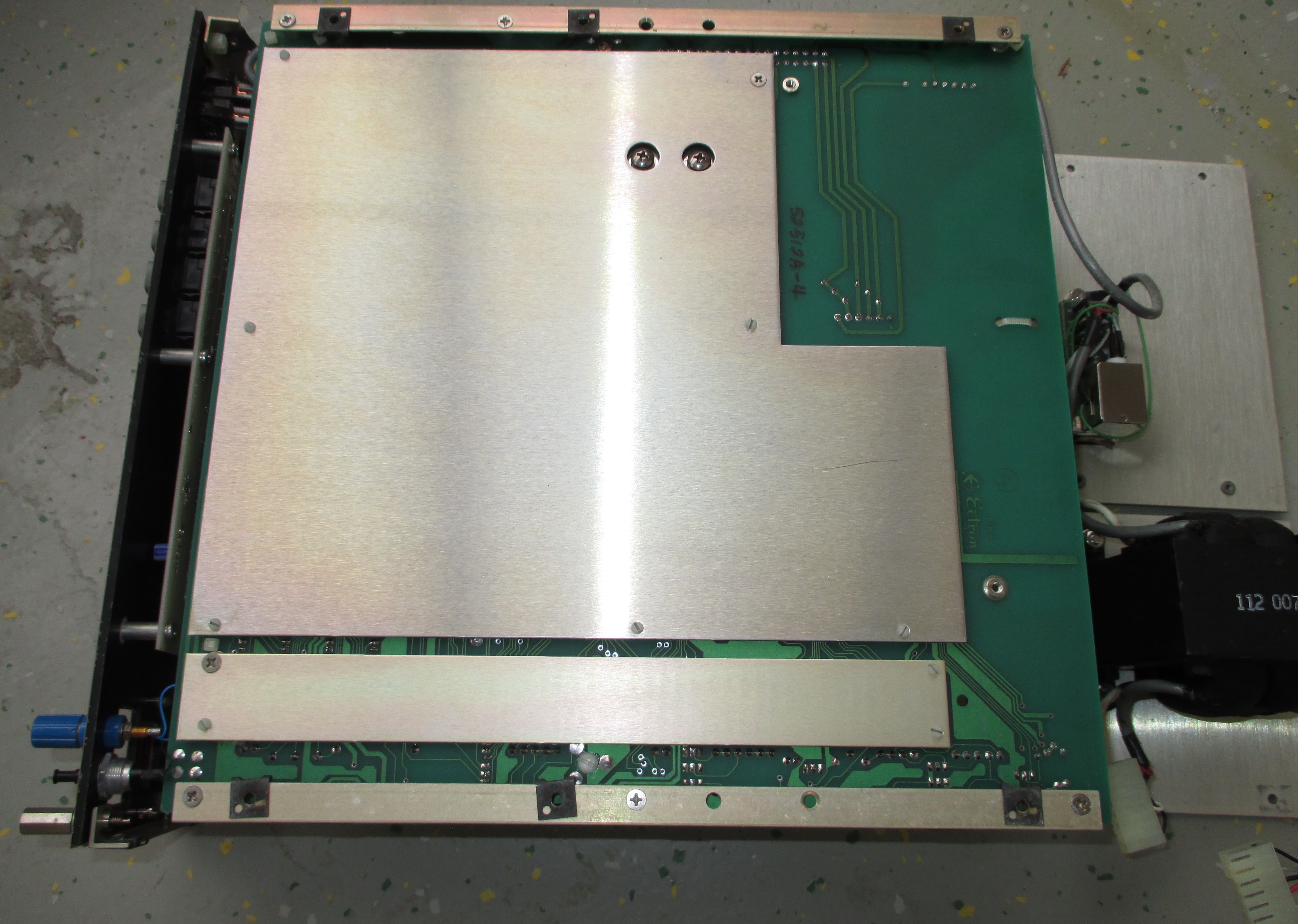
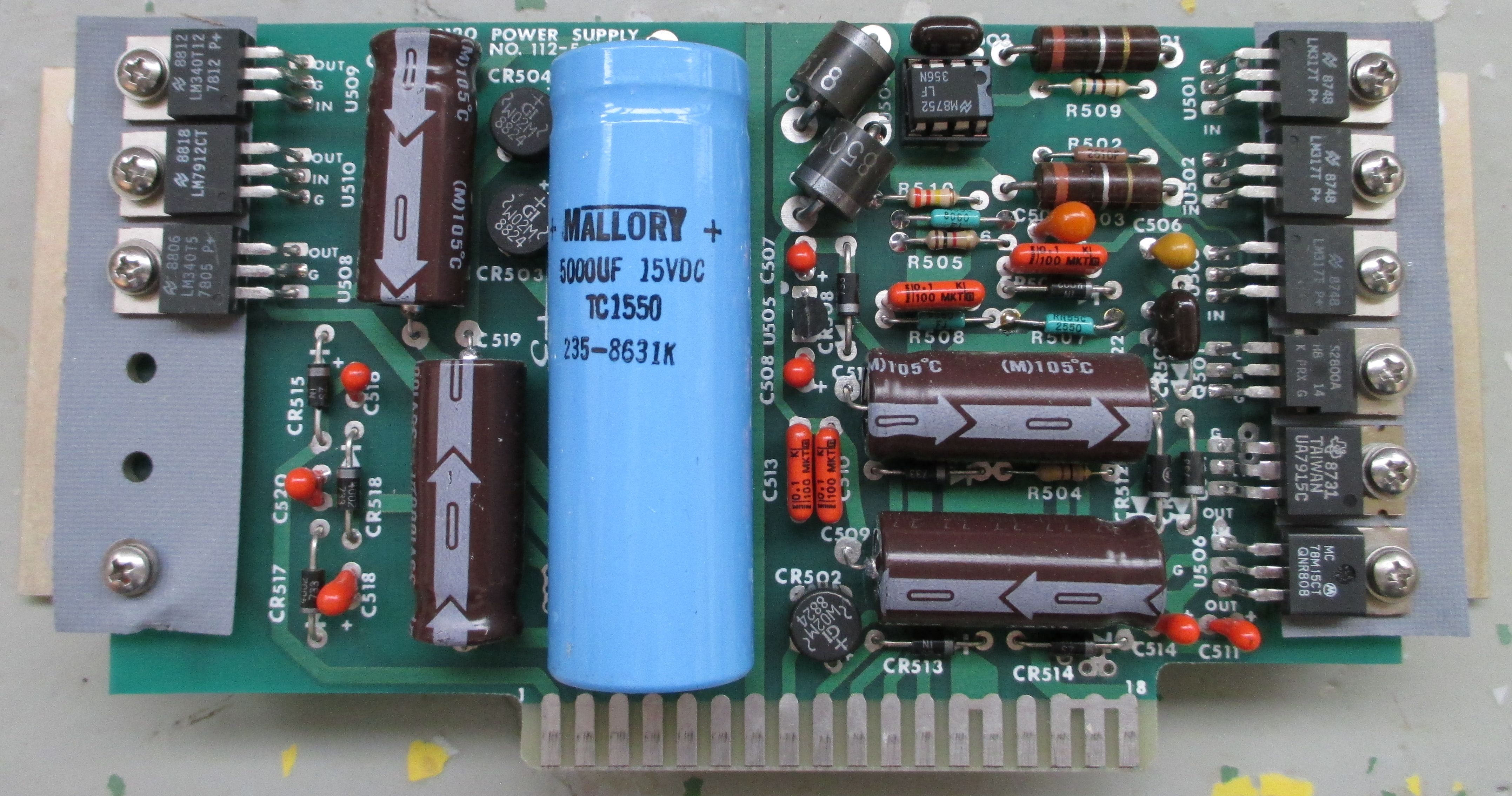
Teardown and repair
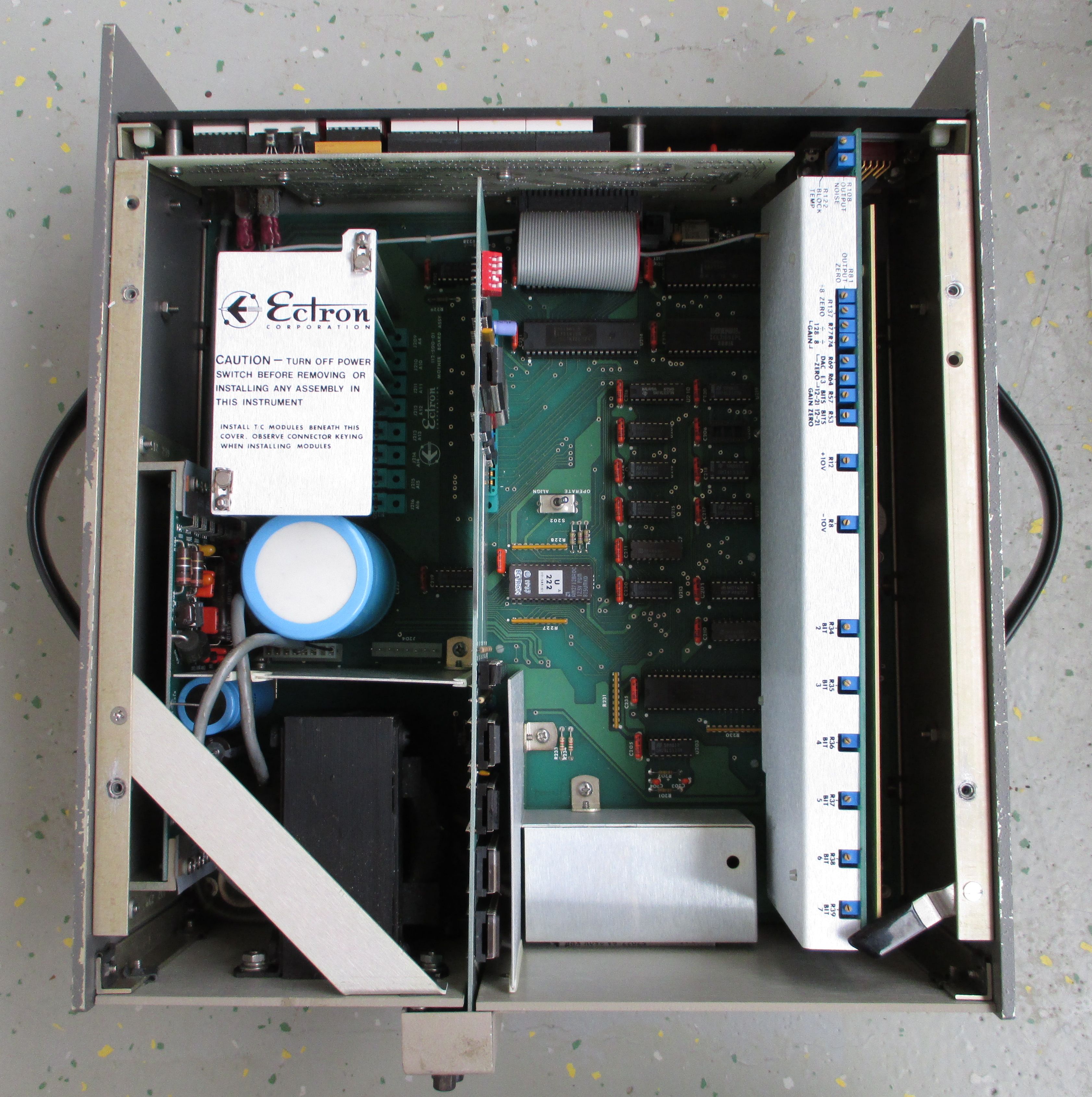

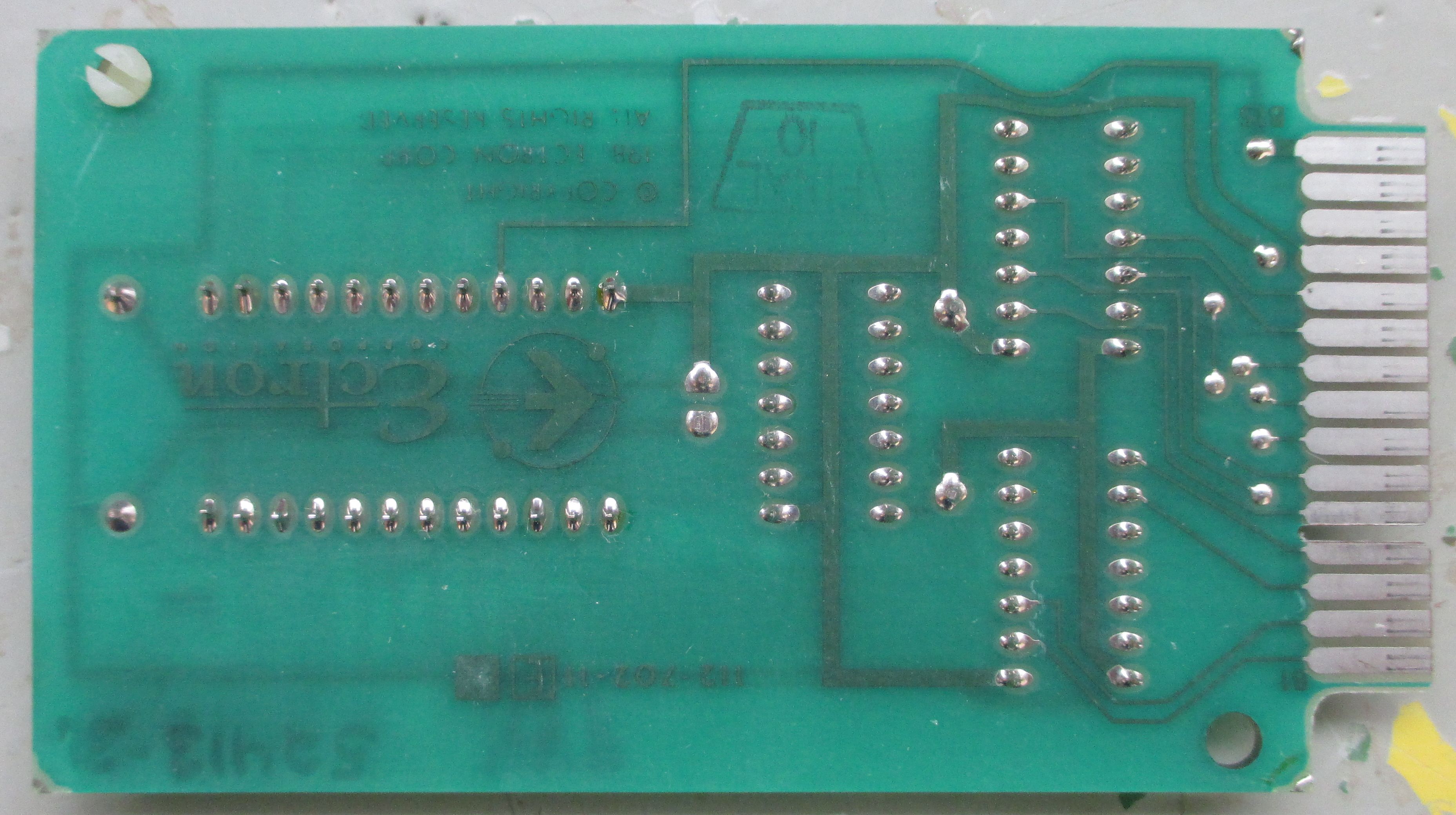
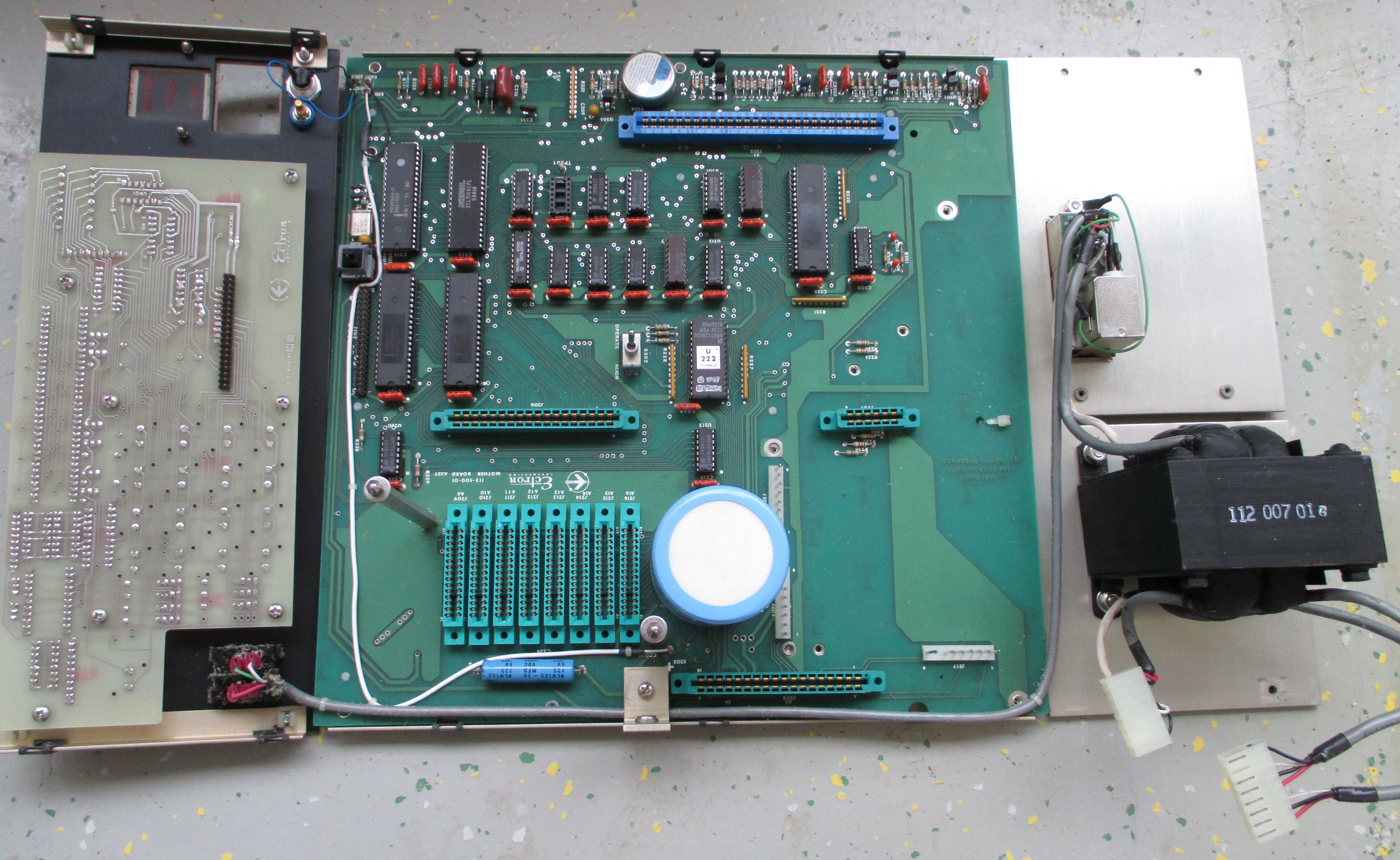
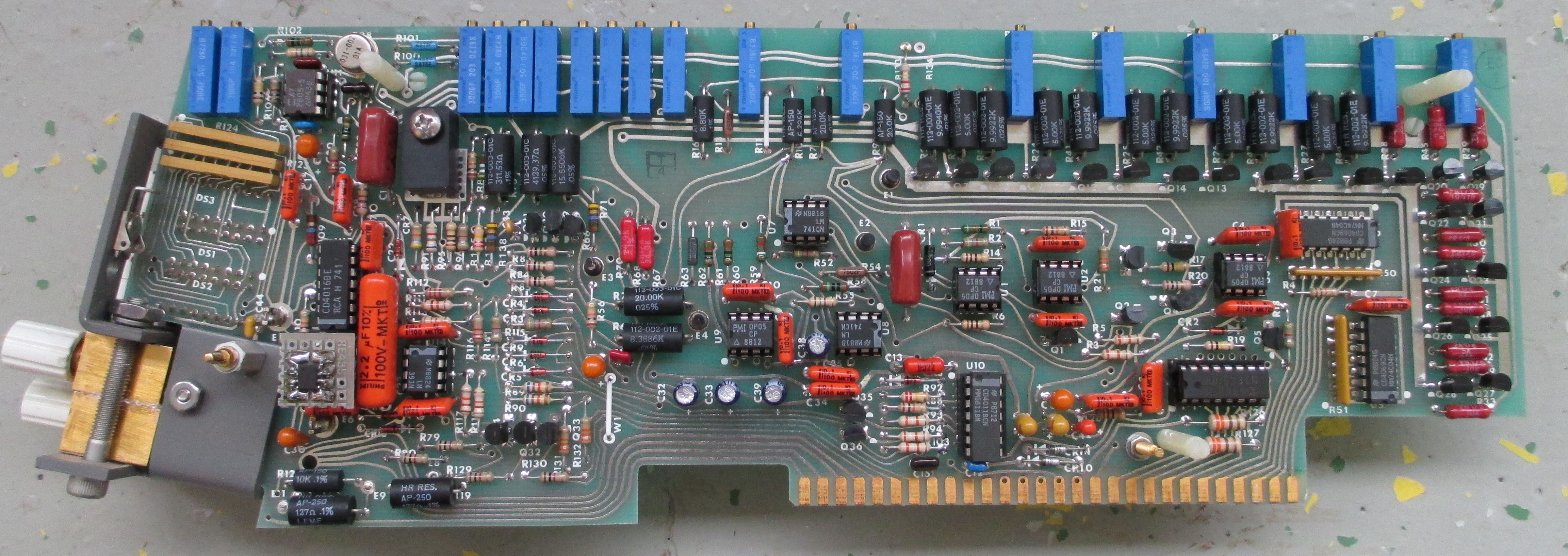
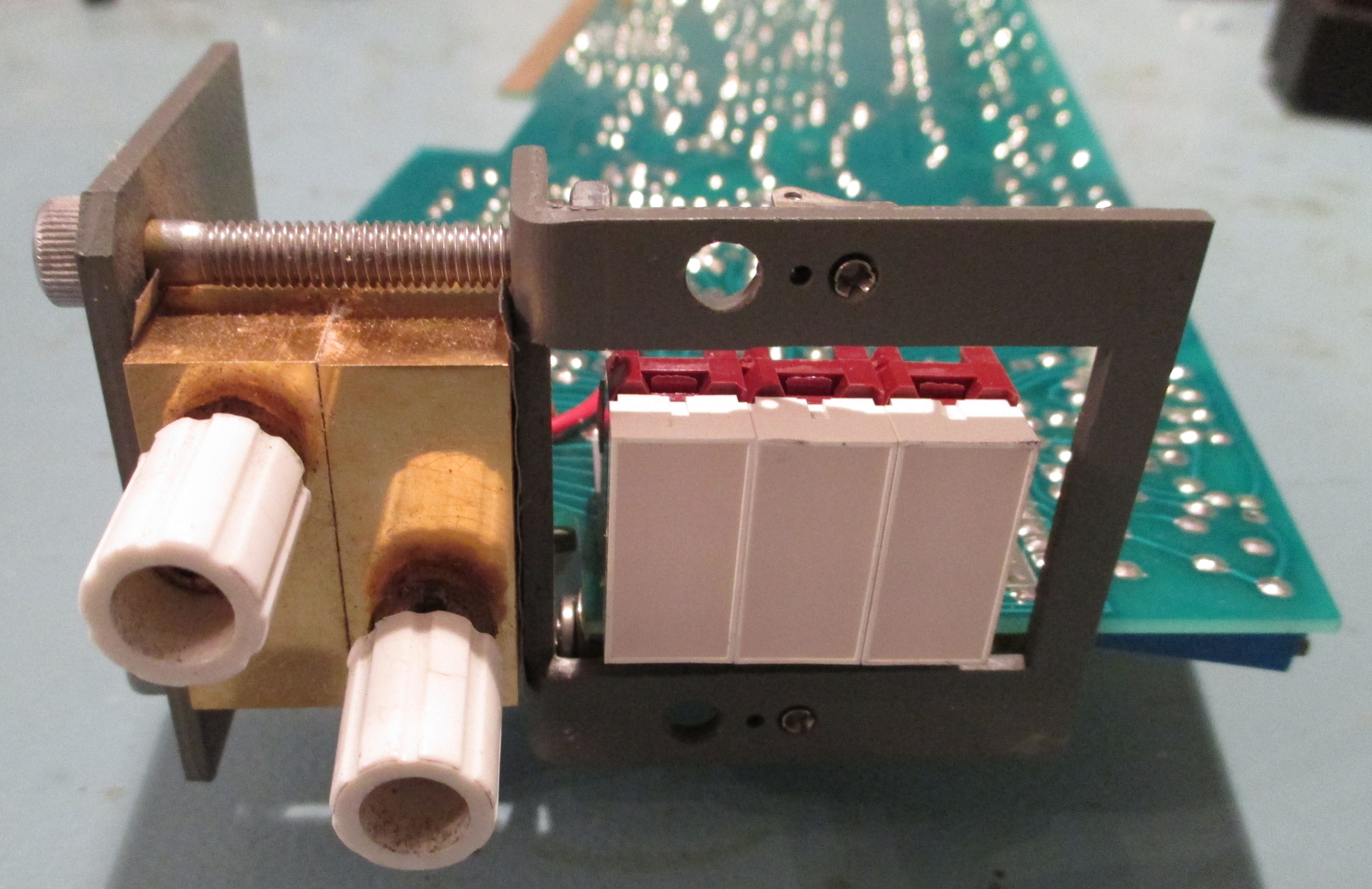
Image 4-5: Shields removed, revealing internal modules of the unit
Since its optimized on high resolution TC-simulation it sports low thermal copper posts in big gold plated copper blocks, which are separately measured for temperature. The Ectron is capable of providing switchable copper and alloy-outputs which makes many different TC-simulation-schemes possible. When in Alloy-mode, the temperature of the copperblocks is measured and used to compensate the desired TC-temperature. The temperature-sensors are not used in copper-mode.

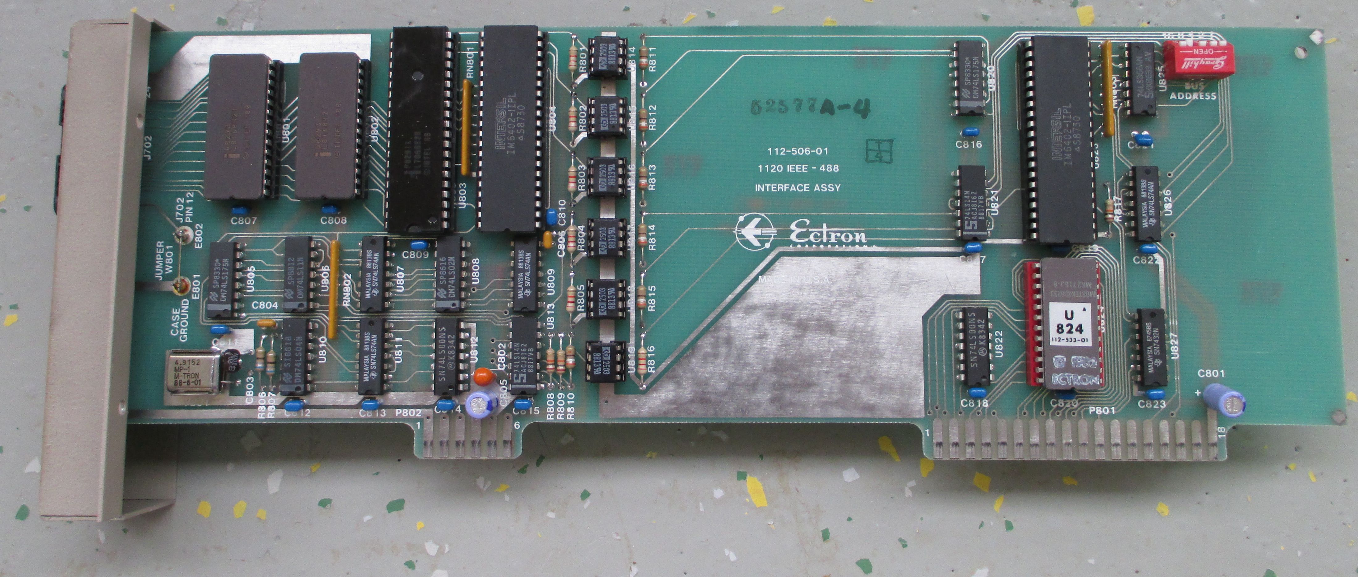
Direct TC simulation for various metal types is optional and added via purchasable card-edge PCB options. Precise conformity to the non-linearity of nine thermocouple types (E, J, K, T, R, S, B, C, N) is controlled these plug-in PCBs, one for each of the types offered. Each thermocouple type module, except type C, includes a ROM chip containing the polynomial equation that corresponds to NIST Monograph 175 (ITS-90).
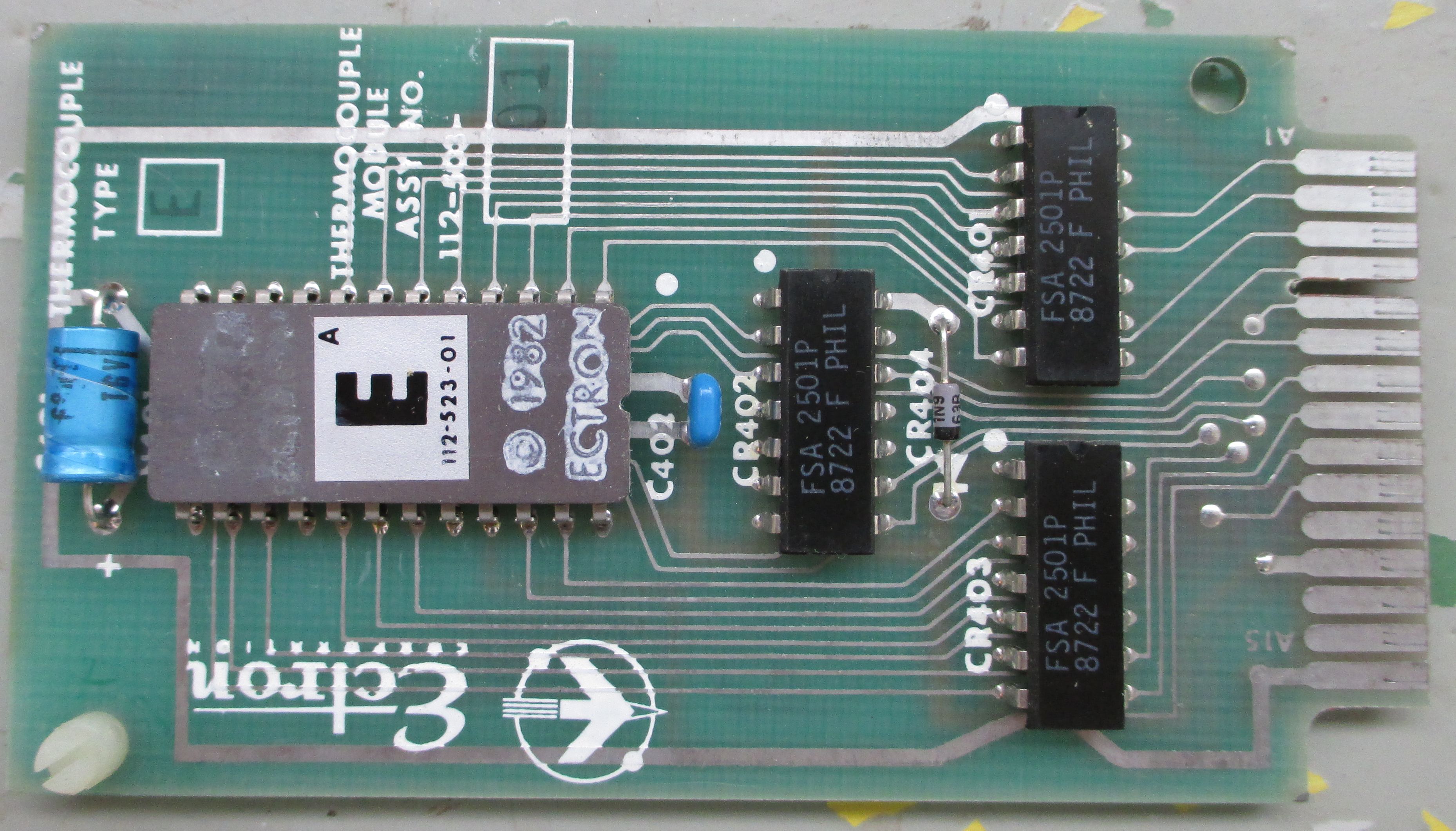
Without the TC module the calibrator is only capable of DC voltage ouput and lacks the TC-functionality. Mdoule is necessary to translate calibrators output voltage which is depended on reference junction temperature (entered via keypad) and the desired simulation temperature which is entered via keypad or GPIB/RS232 interface (both are also optional).
The TC-pcbs and the copper-output blocks are held in place by clamping mechanisms.


![]()
Operation theory and basic analog topology is straightforward. A well selected zener provides +6.3 VDC, which gets converted into +10V/-10V. These ±10V are used by the two separate DACs:
- MSB-DAC is implemented as a discrete precise 11-bit DAC to generate the higher voltages with sufficient resolution and accuracy.
- LSB-DAC is implemented as monolithic standard 10-Bit-DAC-Chip to generate the lower voltages.
The 21-bit word, which is generated by the motherboard-microcontroller, is split into 11 bit MSB and a 10 bit LSB and then fed to the respective DACs mentioned above.
Both DAC output voltages are summed with low offset chopper-amplifier, which is built with discrete components. When the thermocouple-output-mode or the mV-output is activated, the chopper-amplifier activates a switchable gain 1/8 or 1/128 to obtain the needed resolution and low noise at these required low voltages.
| Output Voltage | Amplifier Gain | Output Resolution |
|---|---|---|
| ±1.375…±11.0000 | 1 | 8 µV |
| ±0.085938…±1.375 | 1/8 | 1 µV |
| 0…±0.085937 | 1/128 | 62.5 nV |
The temperature-sensing in the output-copperblocks is realized via selected LM234s. These components are adjustable current sources, which have a linear temperature dependance (see page 7 of the LM234-datasheet). The LM234 is mounted inside each copper-block to measure the temperature individually, while both copperblocks are in intimate thermal contact with each other, but electrically isolated. They are supplied with ±10V from the reference and their outputs are paralleled and measured by an ADC on the motherboard. Then this temperature is used to compensate the simulated temperature when the calibrator is in Alloy-Mode.
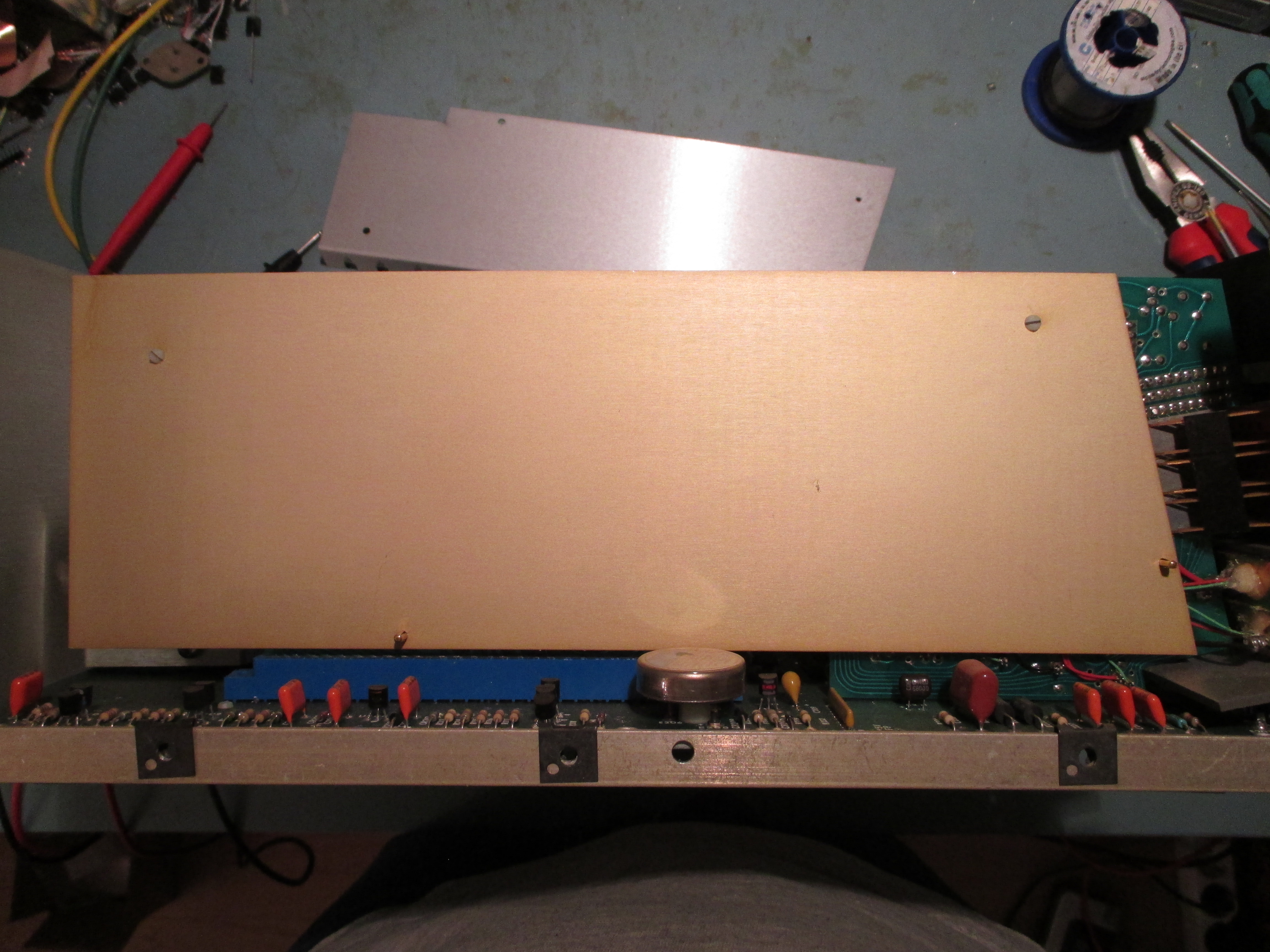
The calibrator was bought with the error-description: “Turns on, responds to commands, output not correct”. While the description was correct, the startup-diagnose found no error.
When i measured the output with my 34465A-DMM and entered different voltage values i found that it indeed misbehaved:
- it produced completely wrong voltages, when i entered a small mV-number it produced several volts with the wrong polarity.
- switched the output polarity via keypad the output-voltage didnt just changed sign, instead it also drastically changed value.
Contemplating about the possible reason for this error i checked the temperature of the components with my fingers to see if anything was obviously defect/shorted and therefore would get hotter.
Bingo:
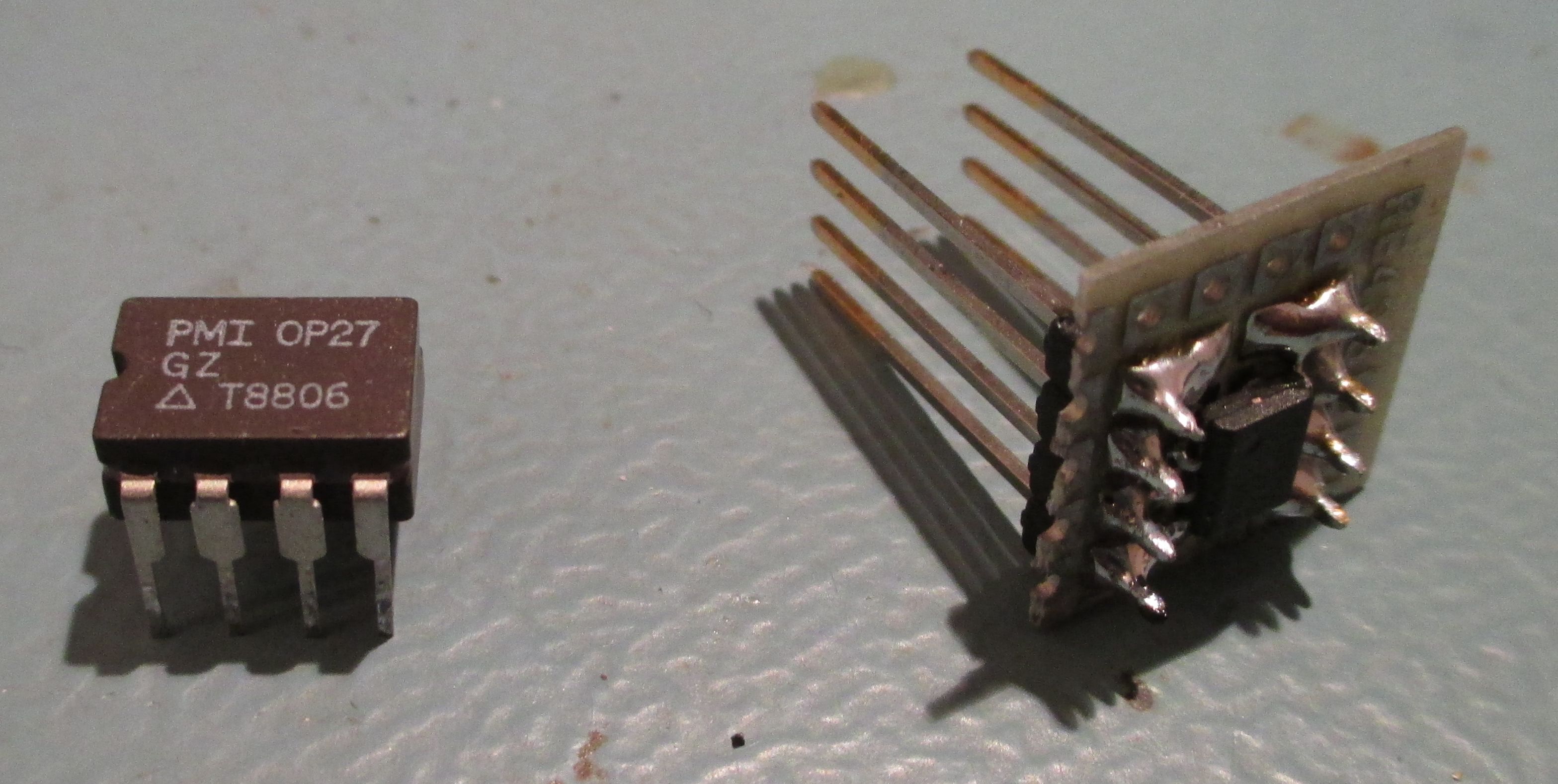
The voltage-regulator-heatsink was indeed hotter than expected and after checking each IC on the mainboard and Analog-Assembly with my fingers, i felt that you could cook eggs on the OP27 which is used as the output-OP-AMP. Since i didnt have a OP27 in DIP-package in my inventory, i quickly build a DIP-adapter with an OPA227 in SMD-package (successor of OP27 according to datasheet).
Test results and summary
After inserting the OPA227-contraption in the OP27-socket and with fingers crossed it worked flawlessly again. The calibrator could use an adjustment to get perfect values compared to my 34465A again, but since the adjustment procedure is rather tiresome due to the many potentiometers which are used in the discrete 11-bit DAC and since my 34465A was last calibrated in 2016 ill leave it at that for now.
Due to its sufficient ±11VDC range and stability it will be a nice workhorse to test different prototypes on my workbench, while the big and heavy Fluke 5440B DC calibrator stays in its cabinet to do longterm-tests with very high stability. The repair was surprisingly easy.
In the following pictures we can see the settling time of the Ectron 1120 after the repair. It took about a week to feel cozy in his new loving home/with the new output-OP-AMP and is now stable. Also visible is the noise and TC at 1V-output voltage.
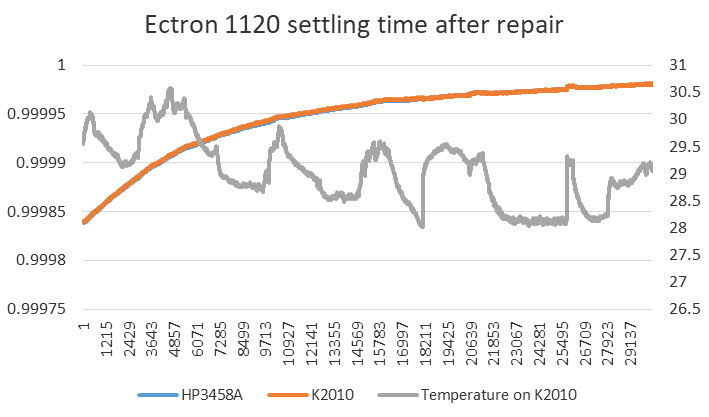
Image : Settling time of Ectron 1120 output
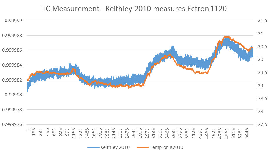
Image : Output noise and TC
Also real-time discussion about this article is welcome at our IRC-chat server: irc.xdevs.com (standard port 6667, channel: #xDevs.com). Web-interface is also mirrored on this page.
Projects like this are born from passion and a desire to share how things work. Education is the foundation of a healthy society - especially important in today's volatile world. xDevs began as a personal project notepad in Kherson, Ukraine back in 2008 and has grown with support of passionate readers just like you. There are no (and never will be) any ads, sponsors or shareholders behind xDevs.com, just a commitment to inspire and help learning. If you are in a position to help others like us, please consider supporting xDevs.com’s home-country Ukraine in its defense of freedom to speak, freedom to live in peace and freedom to choose their way. You can use official site to support Ukraine – United24 or Help99. Every cent counts.
Modified: June 6, 2019, 2:34 p.m.