Contents
- Intro
- Disclaimer
- Initial inspection
- Manuals references
- Diagnostics
- Repair/maintenance workflow
- Boards condition check
- A1 Keyboard PCA
- A2 Front panel PCA
- A3 ANALOG Motherboard PCA
- A4 DIGITAL Motherboard PCA
- A5 Wideband output PCA
- A6 Wideband oscillator PCA
- A7 Current/High resolution oscillator PCA
- A8 Switch matrix PCA
- A9 OHMS,CAL PCA
- A10 OHMS,MAIN PCA
- A11 DAC PCA
- A12 Oscillator control PCA
- A13 Oscillator output, PCA
- A14 High voltage control PCA
- A15 High voltage/High current PCA
- A16 Power Amplifier PCA
- A17 Regulator/Guard crossing PCA
- A18 Filter/PA PCA
- A19 Digital power supply PCA
- A20 Processor PCA
- A21 Rear panel PCA
- A22 Mains power transformer assembly
- Firmware
- Repairs and diagnostics
- Other possible 5700A issues, reported by community
- Tweaks and tricks
- Calibration
- Performance verification
- Connecting 5700A to 5220A current amplifier
- Remote GPIB control software
- Restoration summary
Intro
Today’s Fluke MFC’s are recognized industry standards for many calibration and metrology labs all over the world, just like 8½-digit HP 3458A from DMM world. Started with Fluke 5440A calibrator, today these instruments evolved to Fluke 5730A, one of the very best commercial calibrators money can buy.
In this article Fluke 5700A calibrator will be examined, serviced and calibrated, so get ready for some serious precision instrumentation deal. Fluke 5700A was first introduced in 1988, and today it’s already discontinued model, but still valued as gold in many labs. MFC such as covered here Fluke 5700A is a high precision instrument that can be used as reference stable source to calibrate a wide variety of electrical measurement instruments and equipment. This model available functions and provided ranges allow to test performance, calibrate and adjust practically any handheld and bench multimeters with a reading resolution all the way up to 8½ digits, such as HP 3458A. This MFC in most of user cases allow to replace whole range of expensive calibration standards, and can be itself calibrated by only three reference standards – 1Ω 10KΩ and 10V.
Here’s a complete list 6½+ MFC units, from all vendors:
| Manufacturer | Model | Type | Status | DCV | Ω | DCI | ACV | ACI | Temp | Frequency |
|---|---|---|---|---|---|---|---|---|---|---|
| Advantest | 6166 | V/I/T calibrator | ? | |||||||
| Fluke | 5730A | V/I/R/T calibrator | Current model | |||||||
| Fluke | 5700A | V/I/R/T calibrator | Obsolete model | |||||||
| Fluke | 5720A | V/I/R/T calibrator | Obsolete model | |||||||
| Fluke | 5720A II | V/I/R/T calibrator | Obsolete model | |||||||
| Fluke | 5730A | V/I/R/T calibrator | Current model | |||||||
| Fluke | 5520A | V/I/R/T calibrator | Obsolete model | |||||||
| Fluke | 5522A | V/I/R/T calibrator | Obsolete model | |||||||
| Fluke | 5500A | V/I/R/T calibrator | Obsolete model | |||||||
| Fluke | 5540A | V/I/R/T/C calibrator | Current model | |||||||
| Fluke | 5550A | V/I/R/T/C calibrator | Current model | |||||||
| Fluke | 5560A | V/I/R/T/C/L calibrator | Current model | |||||||
| Fluke | 5440A | V/I/R/T calibrator | Obsolete model | |||||||
| Fluke | 5440B | V/I/R/T calibrator | Obsolete model | |||||||
| Datron | 4800 | V/I/R/T calibrator | Obsolete model | |||||||
| Datron | 4804 | V/I/R/T calibrator | Obsolete model | |||||||
| Datron | 4808 | V/I/R/T calibrator | Obsolete model | |||||||
| Datron | 4708 | V/I/R/T calibrator | Obsolete model | |||||||
| Datron | 4700 | V/I/R/T calibrator | Obsolete model | |||||||
| Datron | 4600 | V/I/R/T calibrator | Obsolete model | |||||||
| Transmille | 3000 | V/I/R/T calibrator | Current model | |||||||
| Time Electronics | 9823 | V/I/R calibrator | Obsolete model |
Table 1: High-end multi-function calibrators
Everything and every detail is important while designing such an instrument. Performance and long-term stability is a base pillar of these complex designs, and many engineers trust their calibrator output without second thought. Some of units may be old, but definitely not obsolete. That’s why usually you don’t see them on sale very often, and the ones you do see go for pretty high prices, very often outside of the price range of even dedicated enthusiasts and volt-nuts.
It was a good combination of hunting and luck to get hands on Fluke 5700A, so now plan for it is to perform full service, repair damaged parts if any, refurbish the unit and perform overall study of instrument and performance test. This also means we will not be doing expensive boards swap, unless absolutely unavoidable and necessary.
As usual, all photos are clickable for high-resolution version.
If you thinking that getting used MFC (or even broken), like this Fluke beast for half of usual market price and fixing it would be easy way to get high-end lab standard, consider mountain of hidden costs and caveats ahead. Re-calibration of top of the line MFC is not a trivial task and cost many thousands of USD, can usually be performed only by professional labs with 90-day calibration loops and characterized standards and even then you need to have multiple standards like Fluke 732B/742A and 3458A’s/8508A’s with calibration plans to ensure long-term calibrator operation and specs. So think clearly, when you entering this market, as it is just endless black hole for funds. But volt-nuts should already know that by now.
There are also special versions of 5700A with options, such as:
| Option | Description |
|---|---|
| 5700A-01 | Rear output terminals |
| 5700A-03 | Wide-band option, extends AC frequency to 30MHz |
| 5700A-04 | Wide-band option and rear output terminals, extends AC frequency to 30MHz |
| 5700A/NAF | |
| 5700A/EP | Upgraded 5700A to meet 5720A specifications |
| 5700A/EP3 | Upgraded 5700A-03 to meet 5720A/03 specifications |
| 5700A/AN | Special model |
| 5700A/AN-1 | Special model |
| 5700A/ANV3 | Special Military model |
| 5700A/CT | Special model |
Table 2: 5700A options and versions
Disclaimer
Redistribution and use of this article or any images or files referenced in it, in source and binary forms, with or without modification, are permitted provided that the following conditions are met:
- Redistributions of article must retain the above copyright notice, this list of conditions, link to this page (/fix/f5700a/) and the following disclaimer.
- Redistributions of files in binary form must reproduce the above copyright notice, this list of conditions, link to this page (/fix/f5700a/), and the following disclaimer in the documentation and/or other materials provided with the distribution, for example Readme file.
All information posted here is hosted just for education purposes and provided AS IS. In no event shall the author, xDevs.com site, or any other 3rd party, including Fluke be liable for any special, direct, indirect, or consequential damages or any damages whatsoever resulting from loss of use, data or profits, whether in an action of contract, negligence or other tortuous action, arising out of or in connection with the use or performance of information published here.
If you willing to contribute or add your experience regarding HP/Agilent/Keysight instruments repairs or provide extra information, you can do so following these simple instructions
Initial inspection
Due to heavy weight (almost 41KG / 90 LBS) and large size, unit was shipped by ground shipping services in two boxes, with foam spacers around face and rear sides. International shipping would require crate and pallet to be done, driving shipping cost up.
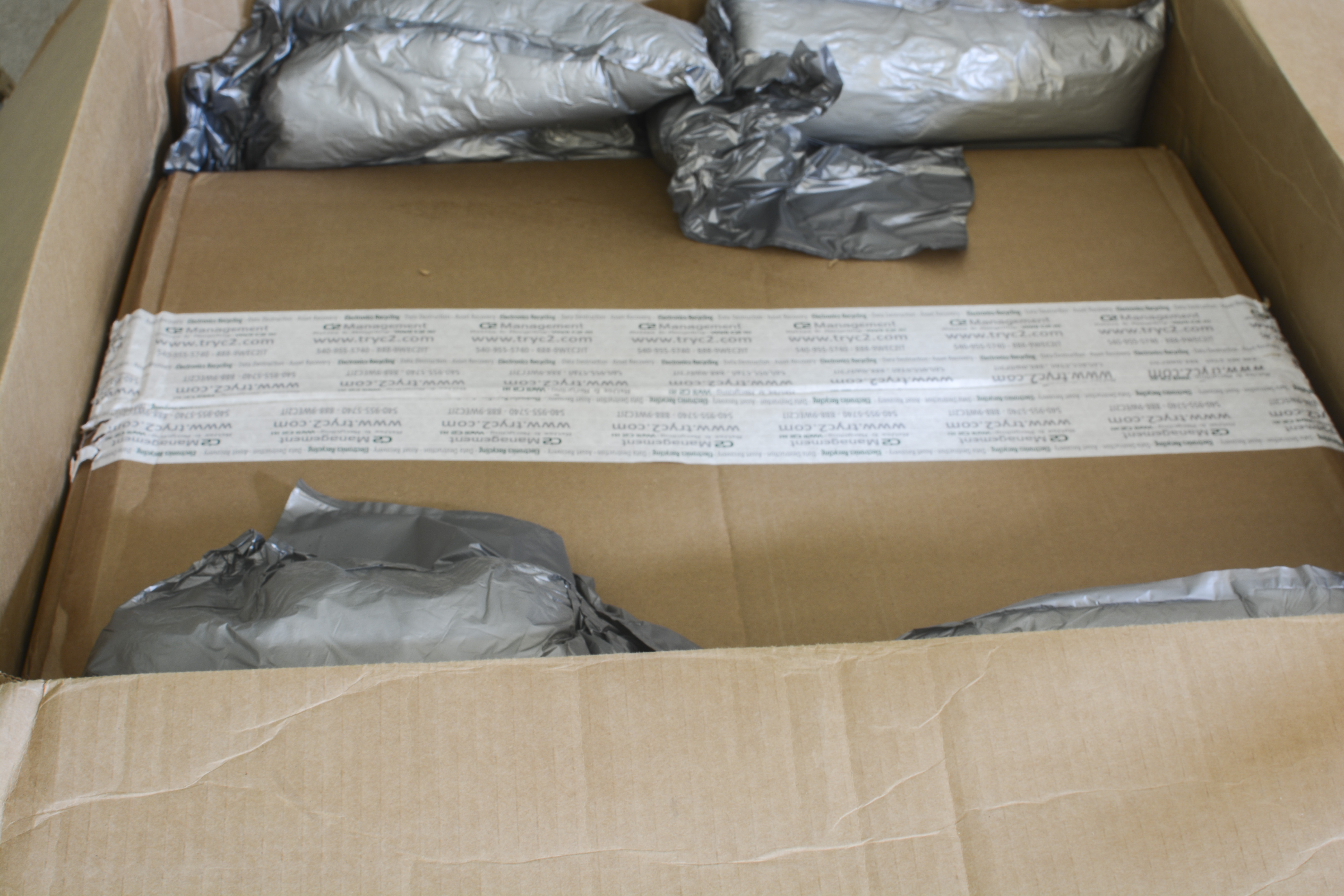
But now it’s now here, so start with see exterior condition inspection.

First of all, it’s a label, which says we are dealing with Fluke 5700A Calibrator today. It’s serial number tells it to be Series I, not later Series II updated unit.
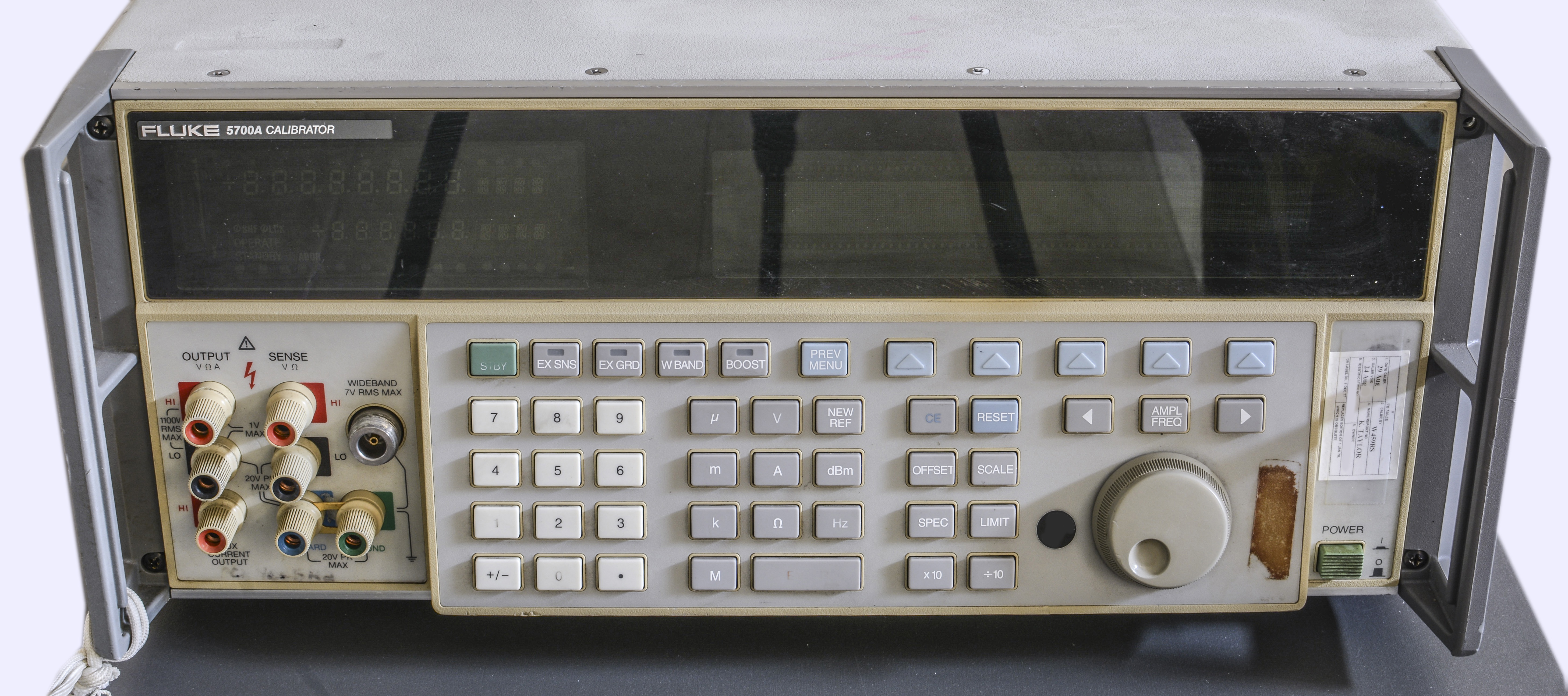
Front panel plastic is yellow due to UV and age, but that’s reversible and not a big deal breaker. No deep scratches or damages visible, that’s good news.
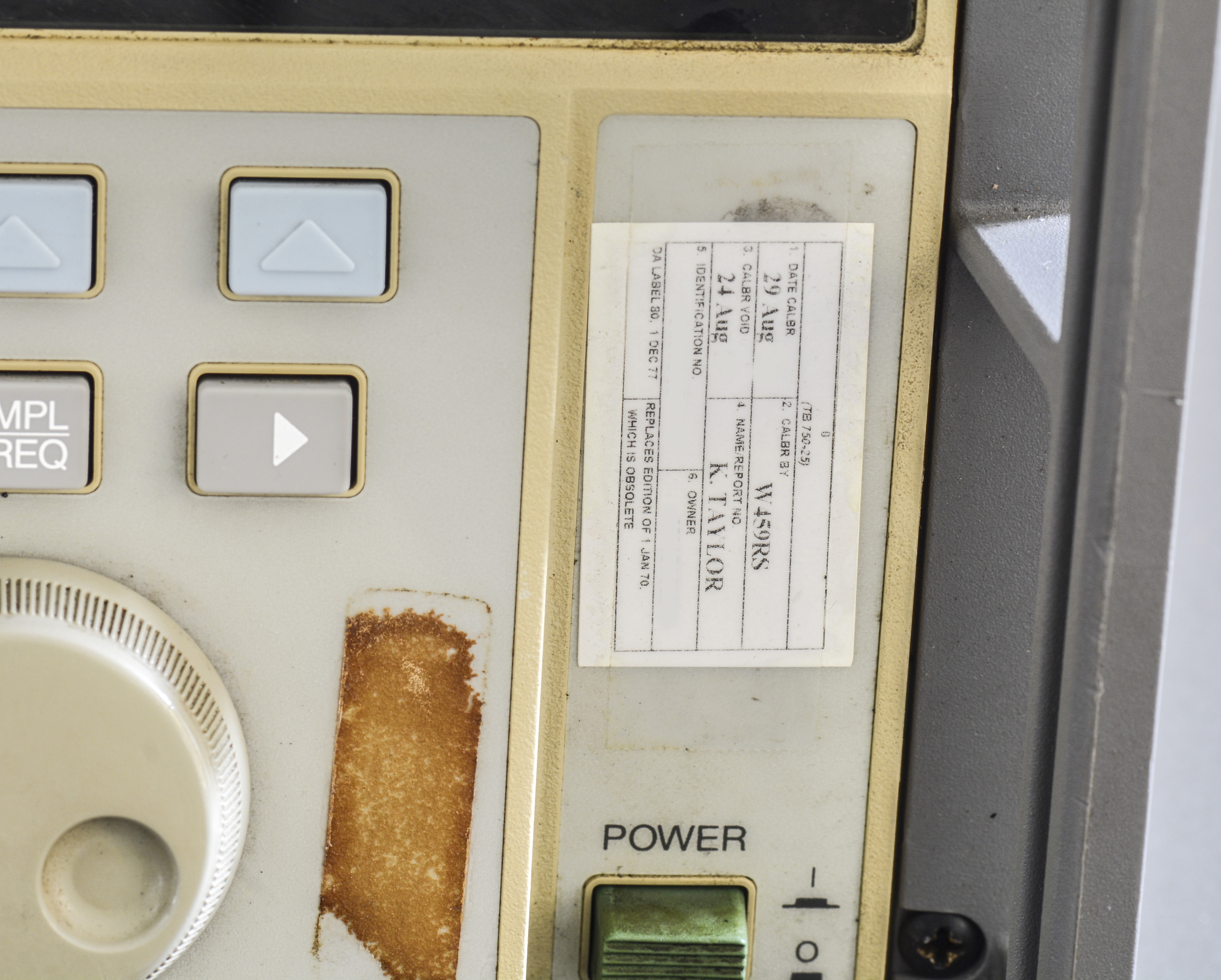
What catches my eye – fairly recent calibration, dated 29 August 2012. This is perhaps a good thing, as unit worked thru most of it’s life and still was fine just 4 years ago. It also does show that both calibration facility and owner was same – W459RS whatever that means. Perhaps some calibration facility which had this 5700A as their working standard? TB 750-25 code on calibration label hints us that it was owned by U.S. Army, as this service tag comply to unclassified AR 750 TMDE Maintenance policies.
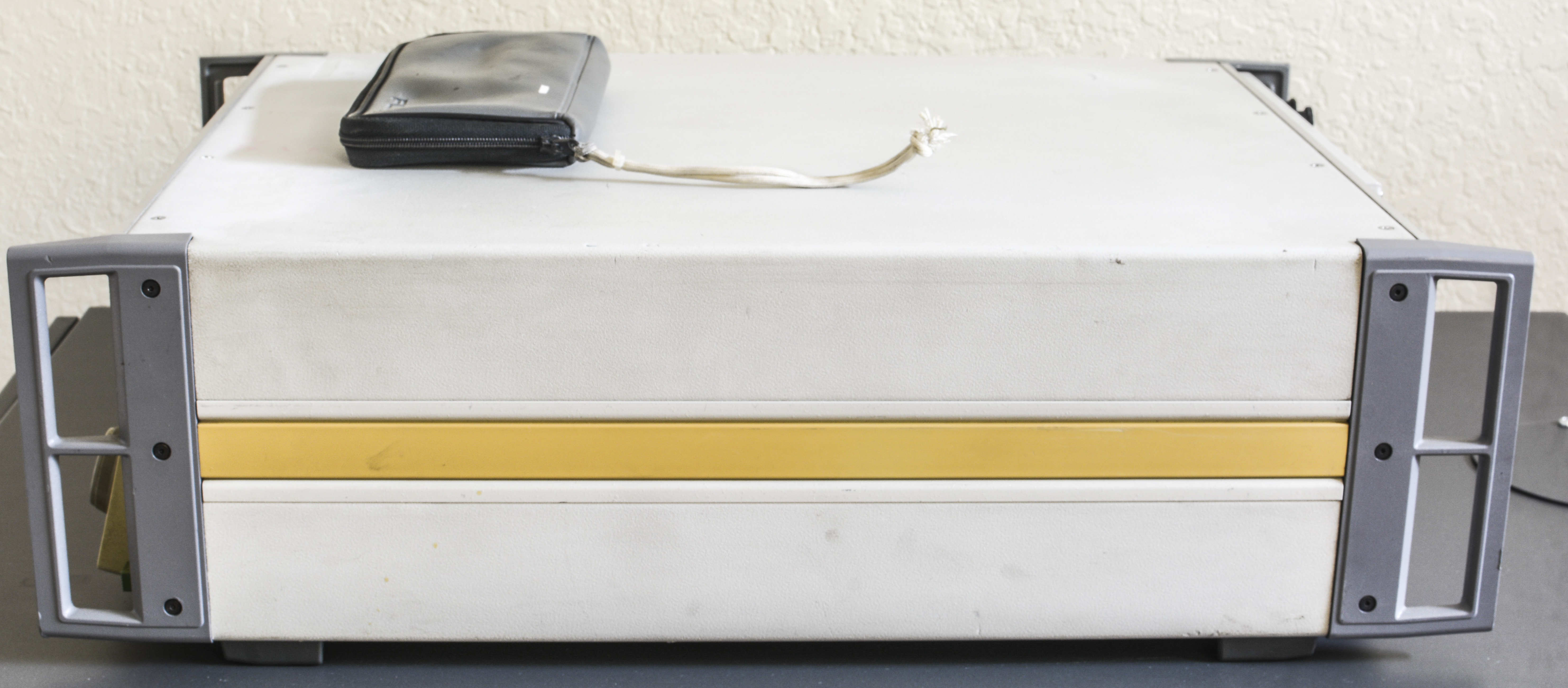
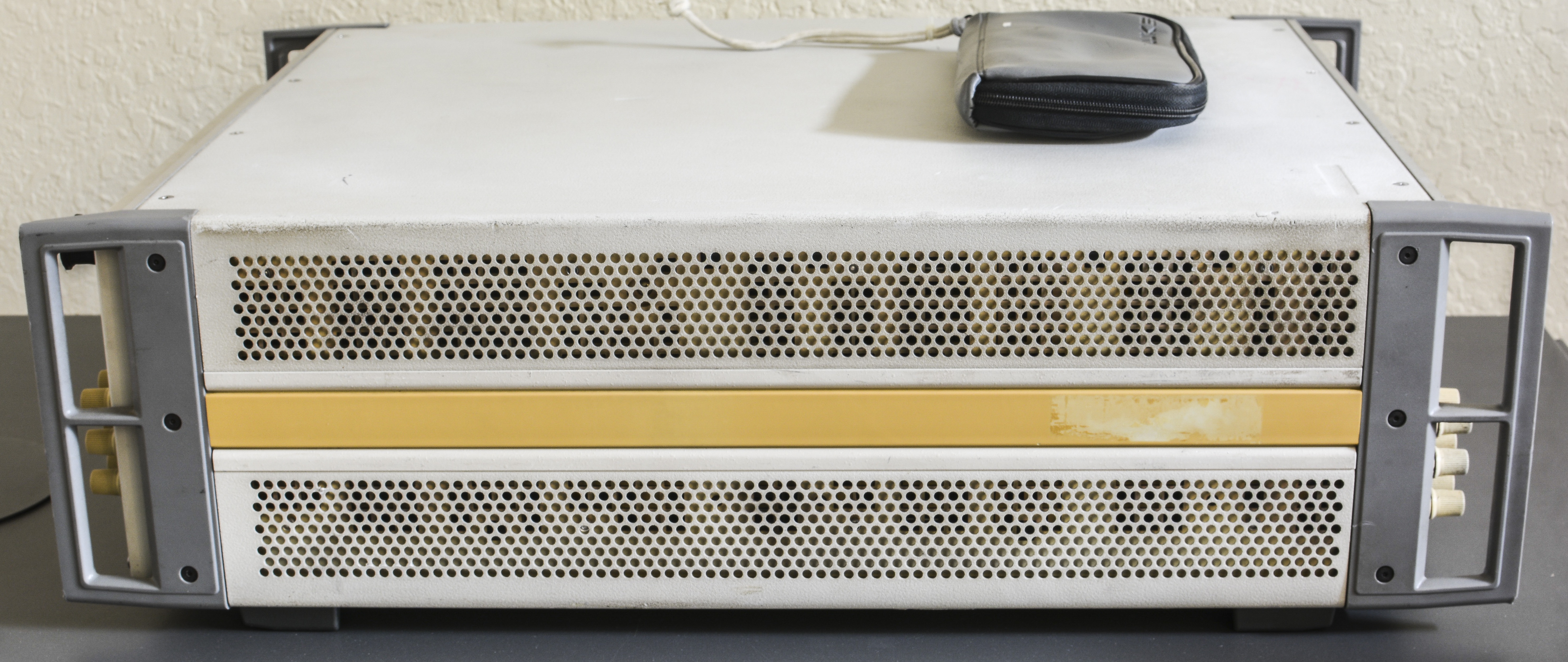
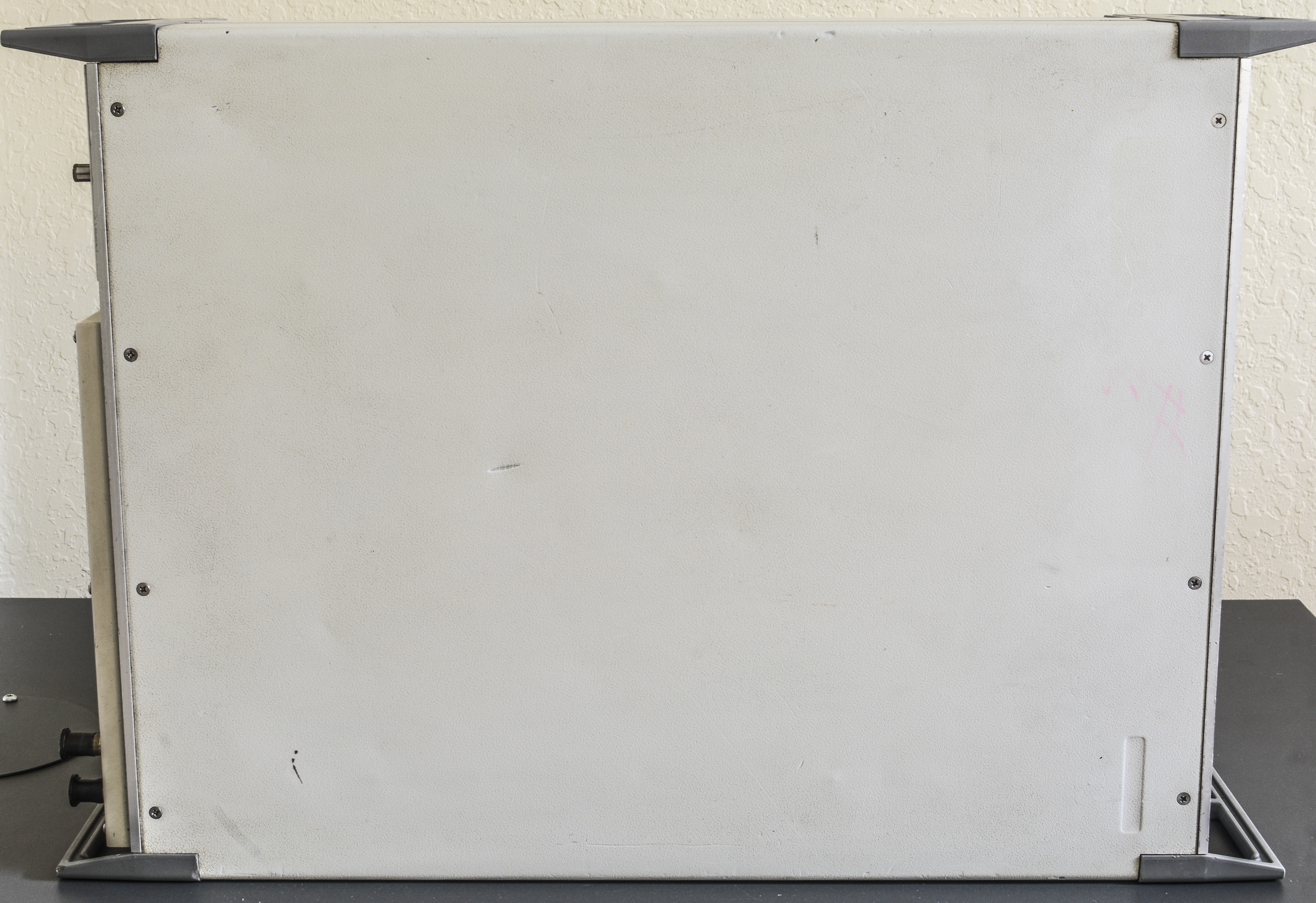
Sides have yellow plastic as well. Whole side of calibrator is covered with vent holes to provide enough airflow to get excess generated heat away. as quick as possible. Given presence of active cooling fans in the unit, we should be ready to see plenty of dust inside.
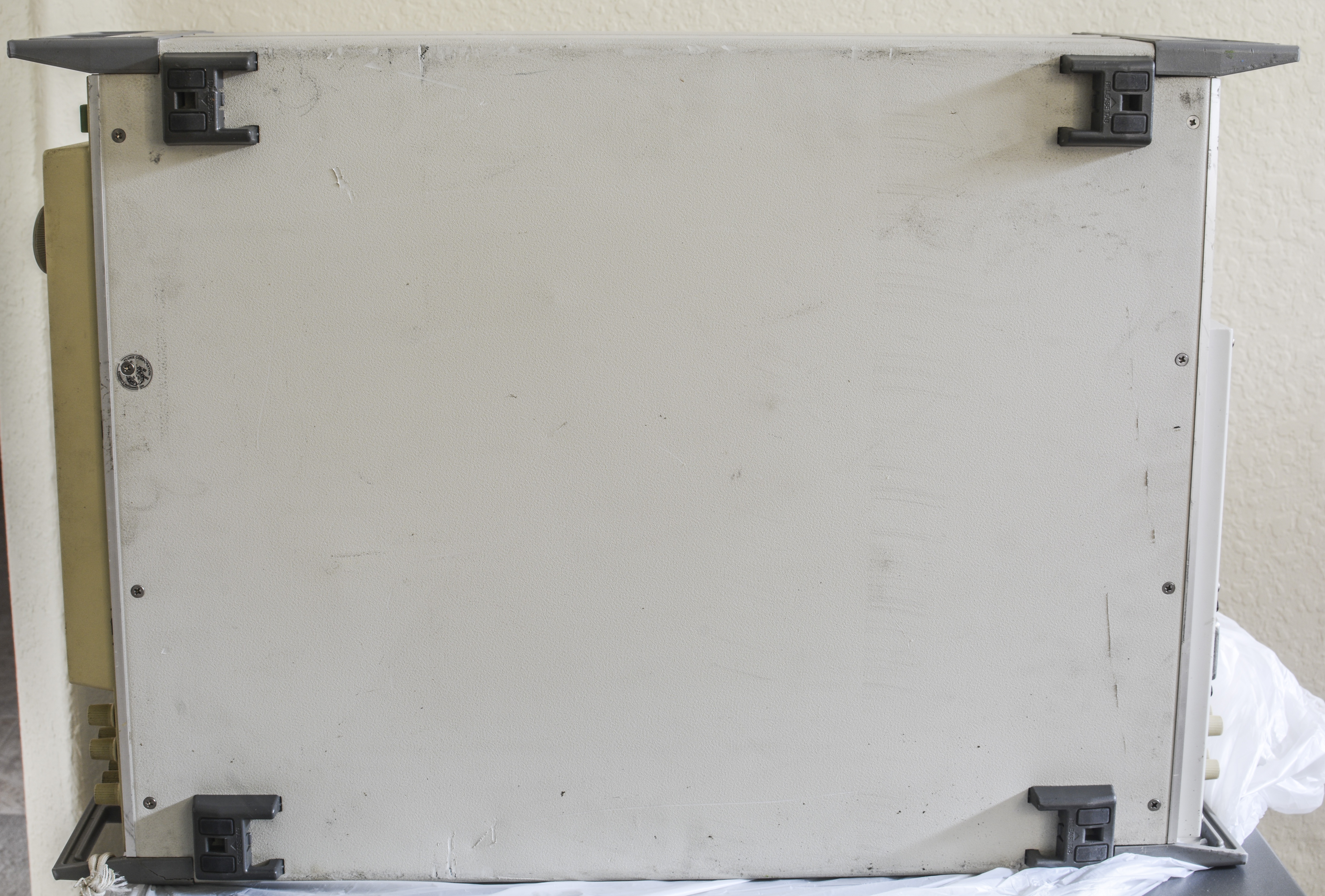
Top and bottom sides have few dents and scratches but no major damage. Label on bottom cover screw was removed before, so somebody had a peek inside.
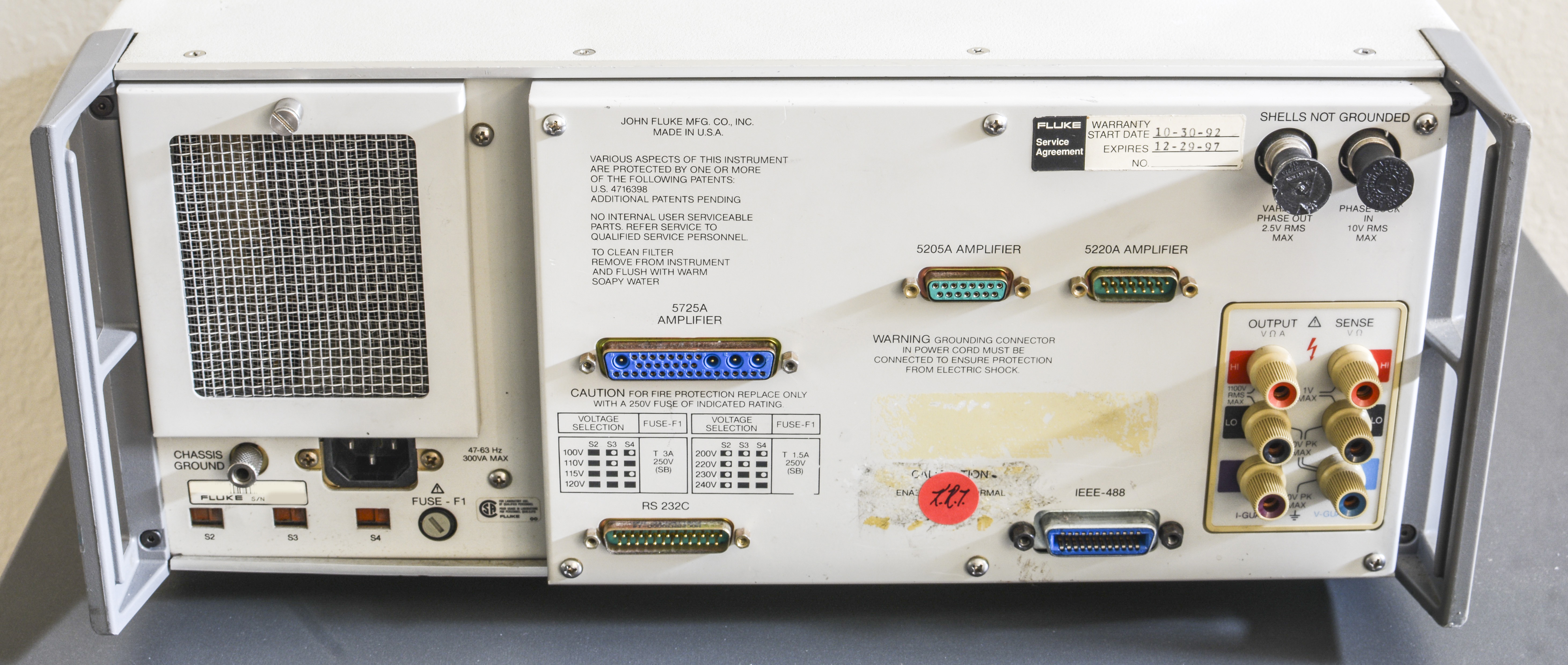
Rear size shows installed rear terminals, which is an option and all connectors in nice shape. There is just a touch of rust on GPIB connector steel nuts, but should be easily cleanable. BNC outputs have caps, likely were never saw a cable attached to them. Air filter is clean from outside, so perhaps it was cleaned not long time ago. This box was covered by Fluke’s service plan warranty once, from 30 October 1992 till 29 December 1997, so it’s likely that unit was manufactured and sold in 1992. Meaning good 24 years till today, which is good and bad news. Good news is analogue references, resistors and parts are very well aged and should be nice and stable. Bad news is that all electrolytic capacitors are likely at their end of life, and other parts perhaps got old enough to fail/reduce performance.

BNCs should be good to go after bit of cleaning. Let’s also check binding banana posts condition.
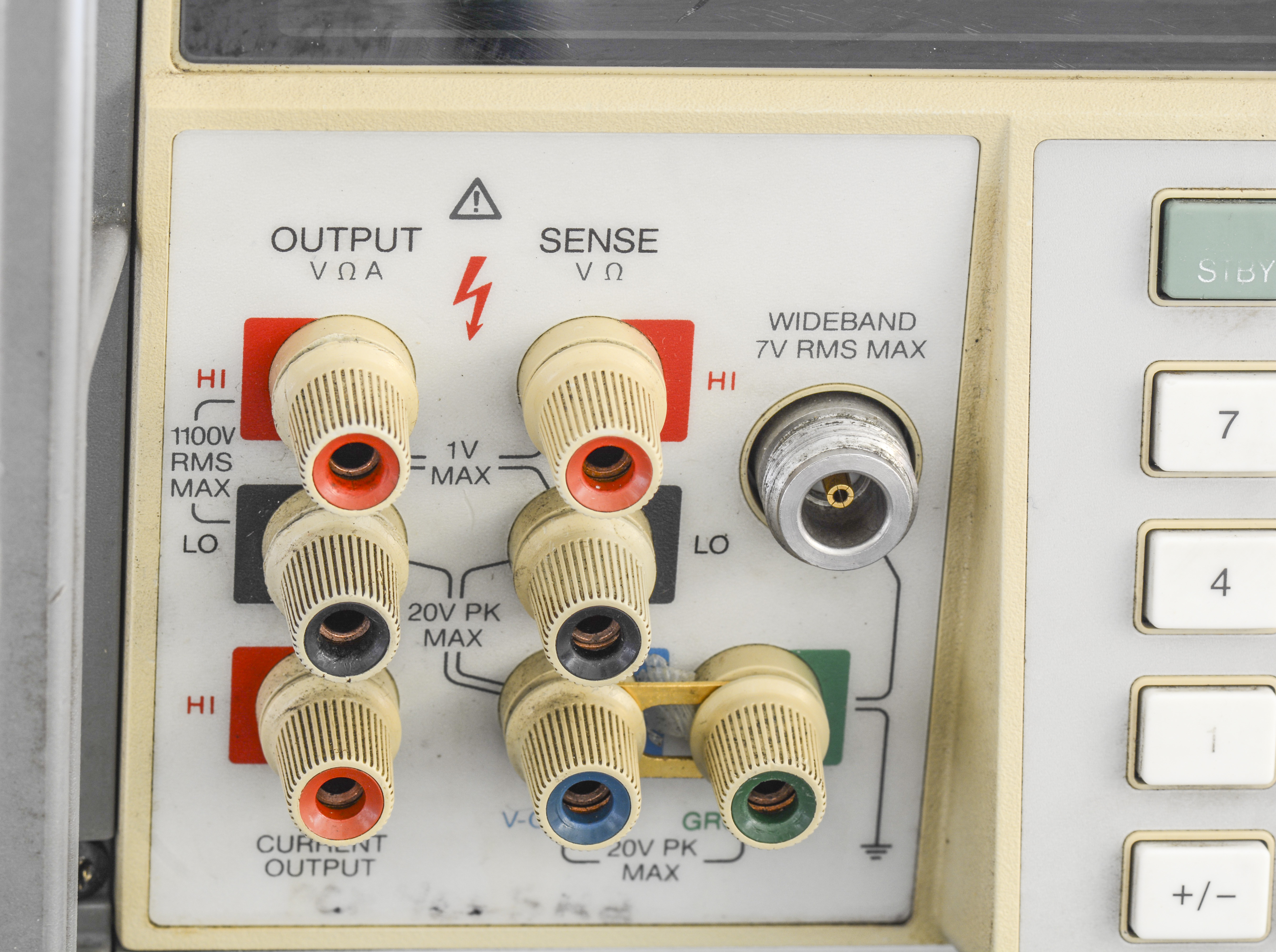
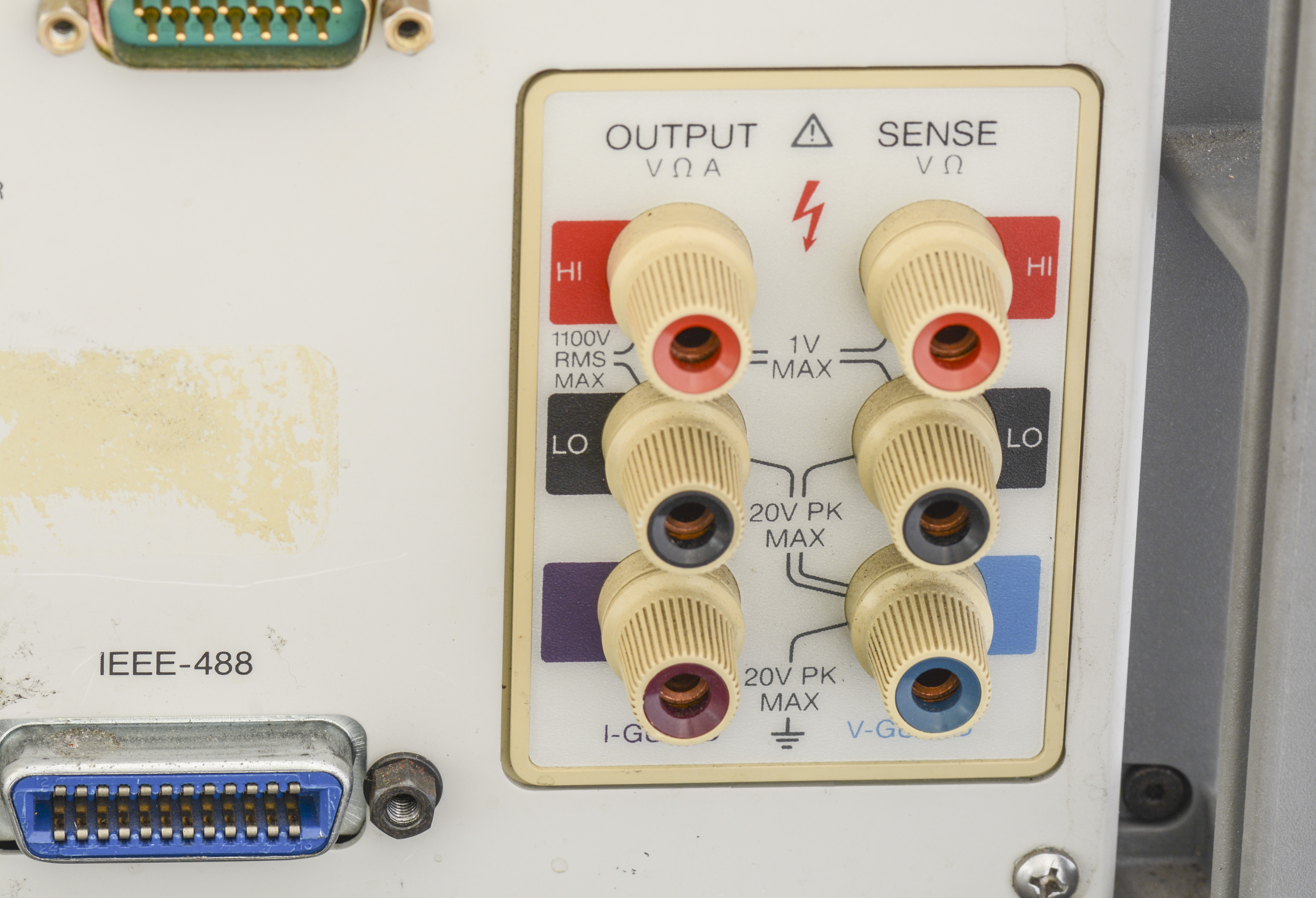
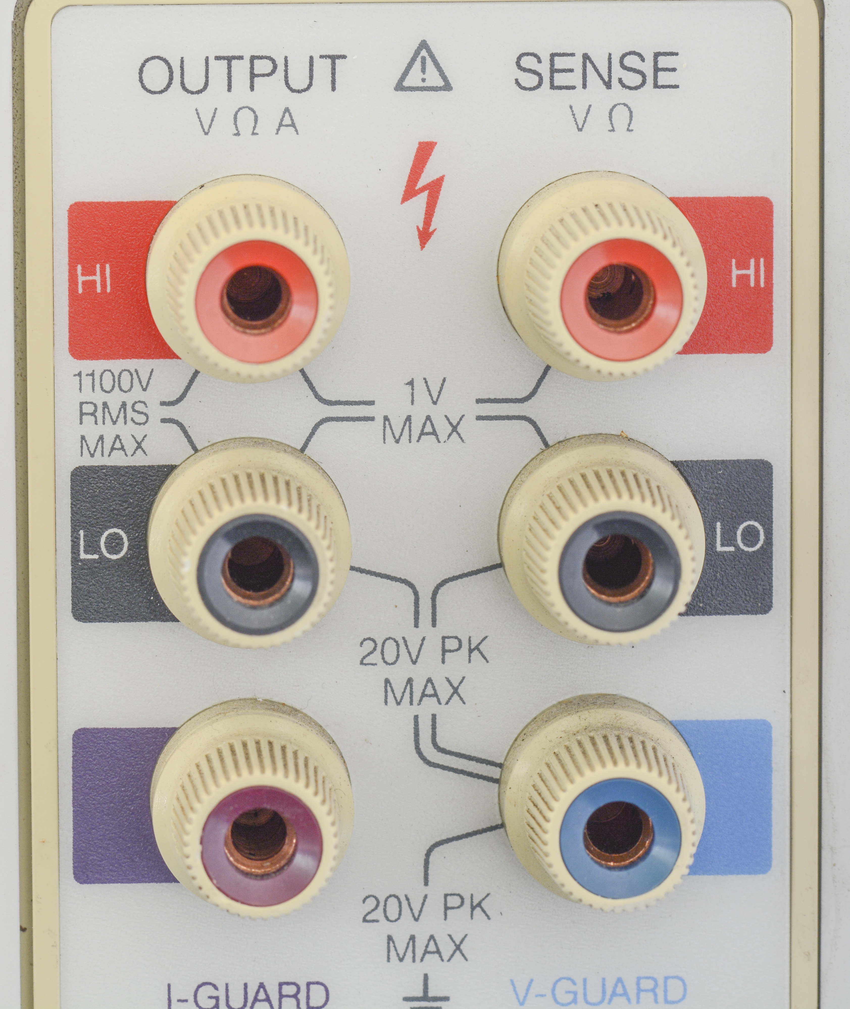
Main HI/LO on front saw some wear and tear, but rear ones are just like new, if not couning yellowed plastic color. These banana posts are pure copper, to provide low-EMF connection to ensure good stable connections. Only downside is that pure copper oxidize easily, so connectors must be often cleaned to ensure best contact. Interesting note, these connectors look exactly like Lowthermal Model 2758 binding posts. I have bought some of these before, they cost about $23 USD each.
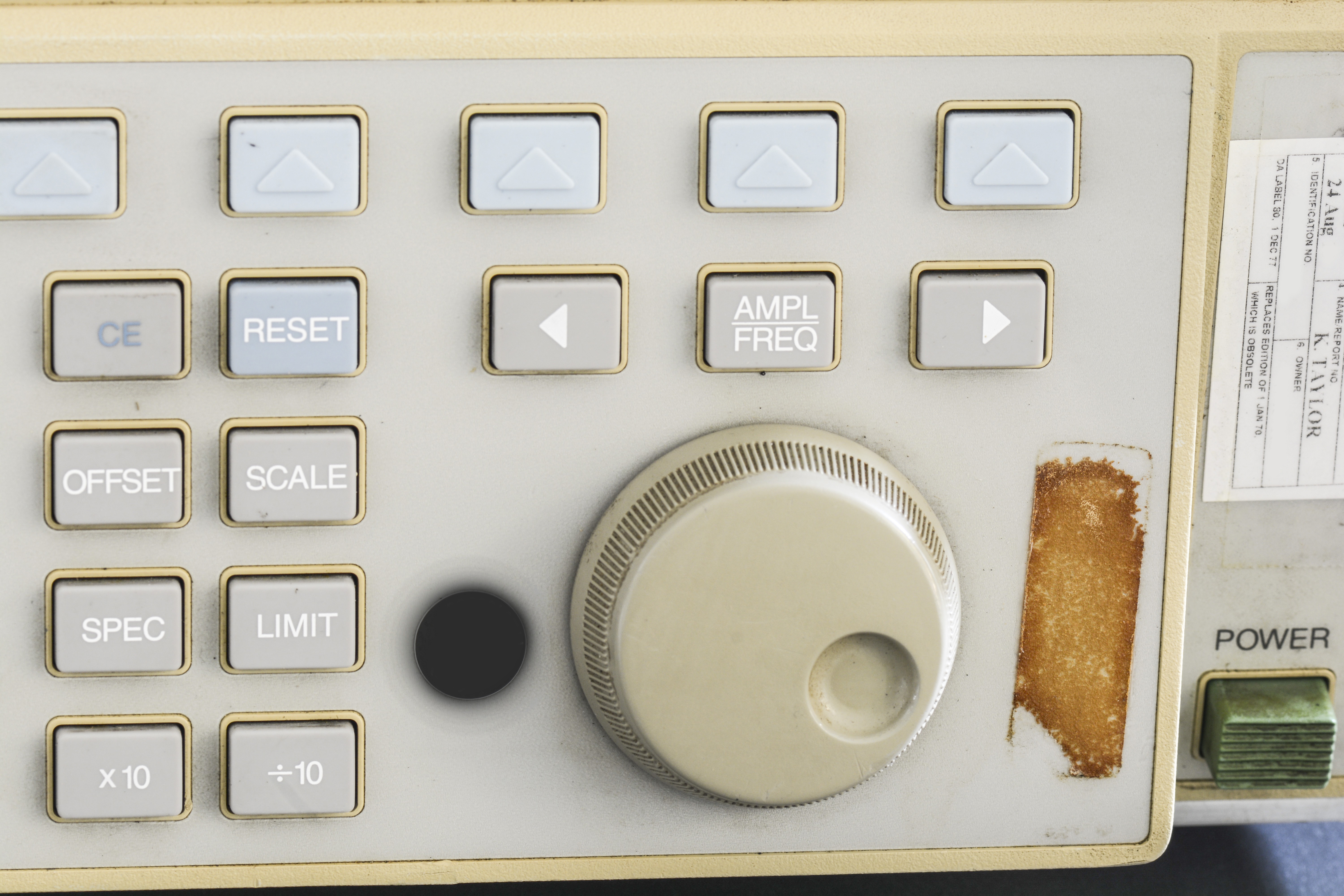

Keyboard looks dirty, some of paint labels on rubber pads are gone, but all keys present and no major damage. Knob is intact as well, just need fair bit of cleaning and anti-yellowing.
It’s worth to run ETIME? command over GPIB to check running time of the unit. The ETIME? query tells you how many minutes the 5700A has been in the power on state since the instrument was built. Unless previous user overwritten ETIME value, or CPU Assembly (Board A20), or the clock/calendar battery (BT1), or the clock/calendar IC (U33) were replaced, this will give likely to give correct time. Reported time is in minutes.
Another handy command is FATALITY?, which returns the list of the fatal faults logged since the list was last cleared by the FATALCLR command. This is sequential command, so it should be run multiple times to get all the strings output. Output format is
<date> <time> <fault code> <fault description string> <EOL>
This will give some idea of unit condition and history, unless previous user cleared faults manually.
To check which hardware is installed and which options are present, next operation can be performed:
- Clear any messages on the right hand display.
- Select Setup Menus
- Select Instmt Config
- Select Show installed s/w and h/w
Calibrator will display all information about installed hardware/software versions.
To clarify which series of calibrator we have, serial number can be used. Any serial number below 6565601 is first-generation Series I, while serial number from 6565601 are updated Series II.
Manuals references
Fluke does provide all main manuals, including service information right on their product page, without requirement of any registration or access requests, unlike Tektronix or Keysight. Thumbs up for Fluke, way to host the data on your product page.
Brochure: The 5700A/5720A MFC: Taking Accuracy to New Level
Fluke 5700A/5720A Series II Operator Guide, May 1996, Rev.1
Fluke 5700A/5720A Series II Operators Manual, May 1996, Rev.2
Fluke 5700A/5720A Series II Operators Manual Supplement, Feb 2008, Issue 5
Fluke 5700A/5720A Series II Operators Manual Supplement, Feb 2008, Issue 9
Fluke 5700A/5720A Series II Service Manual, Nov 2007 w/o schematics
Fluke 5700A/5720A Series II Service Manual Supplement, Issue 6
Fluke 5700A/5720A Series II Service Manual Supplement, Issue 9
Fluke 5700A Service Manual Rev 9, with schematics, BOM only
Fluke 5700A Service Manual Rev 9, with schematics, Schematics Hi-res only
Fluke 5700A/5720A Series II Getting started, March 2002, Rev.2
Fluke 5700A/5720A Series II Getting started Supplement, Issue 6
Fluke 5700A/5720A Series II Remote Programming Reference Guide
Fluke 5700A Instrument Security Procedures
Fluke 5720A Instrument Security Procedures
Fluke 5725A Instrument Security Procedures
Fluke 5725A Getting Started, April 2014
Fluke 5725A Getting Started Supplement, Issue 3
Fluke 5725A Instruction Manual, Jan 1989 Rev.7
Fluke 5725A Instruction Manual Supplement, Issue 4
Fluke 5725A Instruction manual
Tech data: 5700A->5720A Upgrade Service
Fluke 5790A Automated AC Measurement Standard – used for performance verification of 5700A MFC.
Model 5440A-7002 Low Thermal Test Lead Set – Specification
Fluke 5700A, 5720A CE Declaration of Conformity
There is great extensive manual covering Artifact Calibration approach and technology in Fluke 5700/5720, which is worthy read even for people who do not own MFC.
Service notes
First goes the most important document for repairs/maintenance – 570-page service manual. Credits for hosting it freely going to KO4BB portal. We are lucky to also have schematics, list of parts, assembly drawings of the boards included in it!
Fluke 5700A MFC Service Manual with schematics, Rev.9,3/96, March 1996
Fluke 5700A Series II/5720A MFC Service Manual with schematics, Rev.1,3/02, June 1996
5700A Series I and 5700A/5720A Series II difference
According to An evaluation of the 5700A Series II Artifact Calibration document, major change in Fluke 5700A/5720A Series II are related to Artifact Calibration. Artifact Calibration was improved on a number of ranges, to minimize biases. Also interpolation algorithms were changed for AC voltage, particularly at higher frequencies; corrections for the level dependent AC/DC differences at low frequencies (low frequency AC-sensor correction). A new interpolation algorithm is also used for lower ACI ranges. Digital processor board A20 and it’s firmware was changed as a result.
From hardware standpoint, Model 5720/5700 Series II calibrator has a modification to the in-guard microprocessor circuitry to minimize noise in the low millivolt DC ranges. Also, because of the tighter specifications of the 5720A, there may be more selected components in the calibrator circuitry, than in the 5700A Series I.
Diagnostics
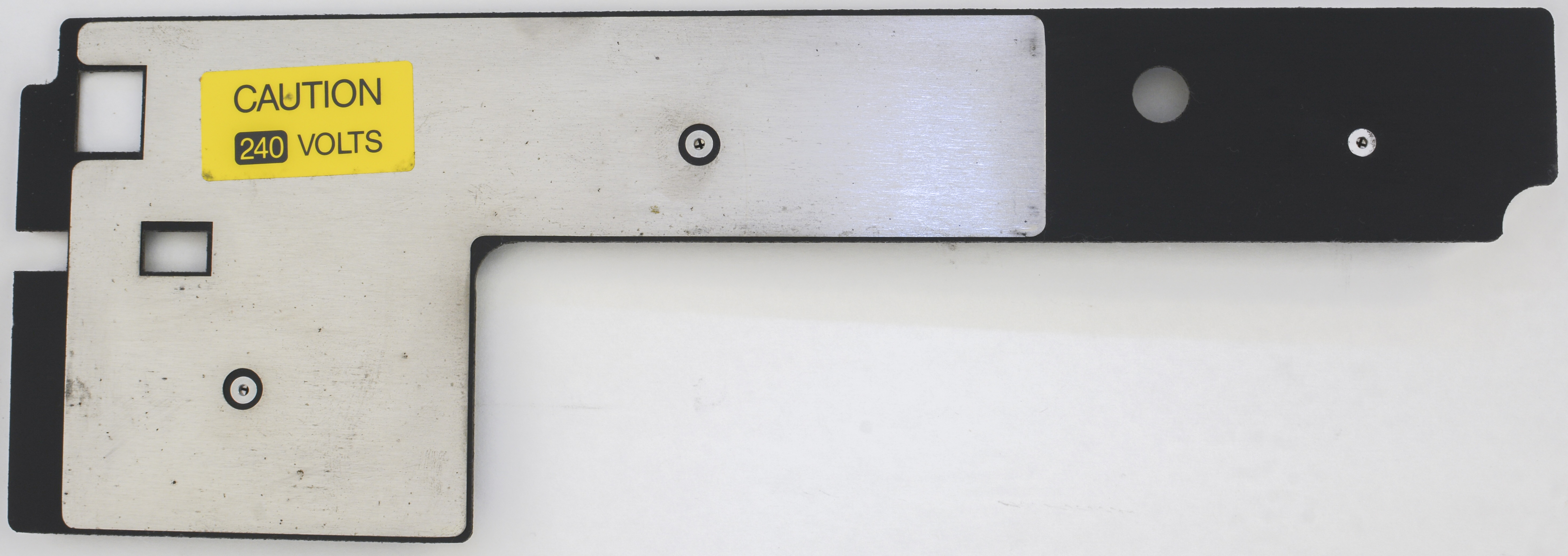
After initial inspection and before any servicing I tried to power the unit on to see if it reports any issues or failures. For initial checks HPAK 3458A, calibrated in June 2015 was used as a reference meter. Checked input power switch settings and unit was powered on.
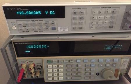
Initial results are very promising, even with only 30 minute power on time (which is not enough for gear like this!) readings are pretty close, considering 4 year old calibration on 5700A.
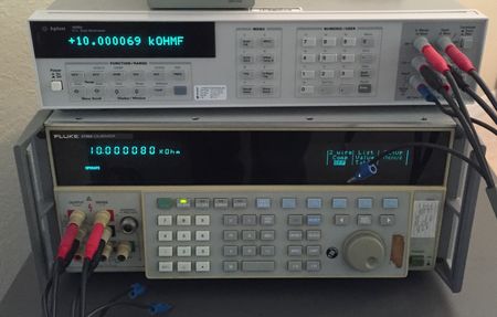
| Fluke 5700A output setting | Agilent 3458A reading | Deviation |
|---|---|---|
| 10.000000 VDC | 10.000005 VDC | +0.5 ppm |
| 10.000080 kΩ | 10.000069 kΩ 4W | -1.1 ppm |
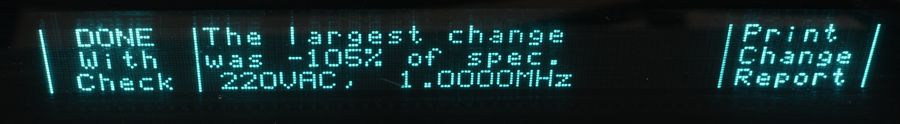
Calibration self-check reported largest change since last calibration is on 220VAC output, highest 1.0000MHz frequency. It’s 105% of the specification.
Simple test program in python was written to talk with MFC over GPIB interface and get some diagnostic data, as well as calibration constants check. Raspberry Pi with linux-gpib package installed and National Instruments GPIB-USB-HS was used to interface calibrator GPIB port. Detailed guide about setting Pi and linux-gpib is also available.
Output is provided below:
Fluke 5700A - detected, S/N XXXXXXX, Version: JA*
This is Series I unit
-i- Reading initial calibration data from 5700A
Unit last calibrated : 1308 days ago
Unit running time : 111438 hr
CAL CONST 6.5V reference voltage : +6.891366504559953E+00
CAL CONST 13V reference voltage : +1.379482200889601E+01
CAL CONST 10KOHM standard resistance : +1.000044087249608E+04
CAL CONST, Zero calibration temperature : +2.245000076293945E+01
CAL CONST, All calibration temp : +2.245000076293945E+01
Calibrator UNDER REMOTE CONTROL
Calibrator STABLE (settled within spec)
Calibrator is cooking report over SERIAL
User string PUD : #2055700A
Fatal errors history: "
 3/17/93  8:18:20  Fault   230: 5725 RESET (power-up or watchdog timer)
 3/30/93  7:07:49  Fault  4014: Sequencer Timed Out Waiting for 5725
10/05/94 18:53:17  Fault   218: 5725 +400V Supply Too Large
10/14/94 20:32:02  Fault   218: 5725 +400V Supply Too Large
11/07/94 12:27:47  Fault   218: 5725 +400V Supply Too Large
11/07/94 12:28:06  Fault   218: 5725 +400V Supply Too Large
 1/06/95  7:56:16  Fault   218: 5725 +400V Supply Too Large
 1/06/95  7:56:39  Fault   218: 5725 +400V Supply Too Large
 1/06/95 12:34:42  Fault   218: 5725 +400V Supply Too Large
 1/25/95  7:59:37  Fault   230: 5725 RESET (power-up or watchdog timer)
 1/25/95  8:00:18  Fault   230: 5725 RESET (power-up or watchdog timer)
 2/03/95  7:02:33  Fault   230: 5725 RESET (power-up or watchdog timer)
 4/07/95 12:53:33  Fault   225: 5725 Fan Not Working
 4/07/95 12:53:34  Fault   225: 5725 Fan Not Working
 4/07/95 12:53:35  Fault   225: 5725 Fan Not Working
 4/07/95 12:53:36  Fault   225: 5725 Fan Not Working
"
HP 3458A detected
 TEMP? = 37.5 C
Fluke 5700A readback output = 10.000000000 V
10V test result: 1.000001492E+01 VDC [deviation 1.4920 ppm]
Program completed!
Running time 111438 hours translates to approximately 12.7 years. Given calibrator’s age – now we can see that half of the time it was running as a standard. No fatal errors were recorded, expect ones related to external Fluke 5725A amplifier in period from 1993 to 1995. It’s almost too good to be true to believe that in all these years of operation no faults were developed in calibrator.
Also serial print log of calibration constants and check was captured:
------------------------------------------------------------------------
    JOHN FLUKE MFG. CO., INC.     S/N XXXXXXX        5700A CALIBRATION CHECK
    PRINTED ON  3/28/16 AT 23:55:21 5700A  S/N XXXXXXX
    ------------------------------------------------------------------------

    ------------------------------------------------------------------------
                                MODULES PRESENT
    ------------------------------------------------------------------------
    Software Revision JA*
    Switching Matrix
    DC Volt Module
    AC Volt Module
    220V Module
    1100V/2A Module
    Current Module
    Ohms Module
    Wideband Module
    Hires Osc Module
    Rear Panel
    ------------------------------------------------------------------------
                   ARTIFACT CALIBRATION DATES AND TEMPERATURES
    ------------------------------------------------------------------------
    Specification Interval:     1 year

    MAIN OUTPUT:   (Most recent)   8/28/XX,  22.5 Degrees C
                      (Previous)   8/27/XX,  22.3 Degrees C
                      (CalCheck)   8/28/XX,  22.5 Degrees C
Worth to note resistance values for further checks:
   ------------------------------------------------------------------------
                            RESISTANCE OUTPUT SHIFTS
    ------------------------------------------------------------------------
            Point             Full Scale Shift                Spec   Shift
                                                              (+/-) (% spec)

     0.0000000  Ohm      0.0000000  Ohm   0.00   Ohm         0.00 Ohm    0.00
     0.9998249  Ohm      0.0000000  Ohm   0.00   ppm       110.00 ppm    0.00
     1.8995690  Ohm      0.0000000  Ohm   0.00   ppm       110.00 ppm    0.00
      9.999934  Ohm       0.000000  Ohm   0.00   ppm        33.00 ppm    0.00
     18.999101  Ohm       0.000000  Ohm   0.00   ppm        31.00 ppm    0.00
     100.00187  Ohm        0.00000  Ohm   0.00   ppm        20.00 ppm    0.00
     189.99523  Ohm        0.00000  Ohm   0.00   ppm        20.00 ppm    0.00
     0.9999919 kOhm      0.0000000 kOhm   0.00   ppm        15.00 ppm    0.00
     1.8999967 kOhm      0.0000000 kOhm   0.00   ppm        15.00 ppm    0.00
     10.000080 kOhm       0.000000 kOhm   0.00   ppm        14.00 ppm    0.00
     18.999695 kOhm       0.000000 kOhm   0.00   ppm        14.00 ppm    0.00
     100.00133 kOhm        0.00000 kOhm   0.00   ppm        16.00 ppm    0.00
     189.99286 kOhm        0.00000 kOhm   0.00   ppm        16.00 ppm    0.00
     1.0000017 MOhm      0.0000000 MOhm   0.00   ppm        23.00 ppm    0.00
     1.8999562 MOhm      0.0000000 MOhm   0.00   ppm        24.00 ppm    0.00
      9.999382 MOhm       0.000000 MOhm   0.00   ppm        46.00 ppm    0.00
     18.999034 MOhm       0.000000 MOhm   0.00   ppm        55.00 ppm    0.00
     100.00848 MOhm        0.00000 MOhm   0.00   ppm       130.00 ppm    0.00
Full serial log output, Fluke 5700A 28 March 2016, initial.
Performed also automatic self-tests routines and the more thorough self-diagnostics which takes about 1 hour to complete. No test failures were reported. Cal check was also performed without errors. Tested DCV, ACV, DCI, ACI, resistance, and wideband outputs using a calibrated HPAK 3458A-002 and uncalibrated Fluke 8920A. All readings were close, even though the last calibration was four years ago.
Now time to tear unit apart, very carefully clean any dust, and do service if needed.
Repair/maintenance workflow
In this section we will do some maintenance to the unit, replace old electrolytic capacitors in power supplies and clean dust inside. Great care will be taken on analog section PCBA’s handling to avoid contamination and reduce leakage risks. This means using gloves and face mask to reduce chances of sensitive analog PCBAs contamination.
Boards condition check
Location of all modules and boards is readily provided from service manual.
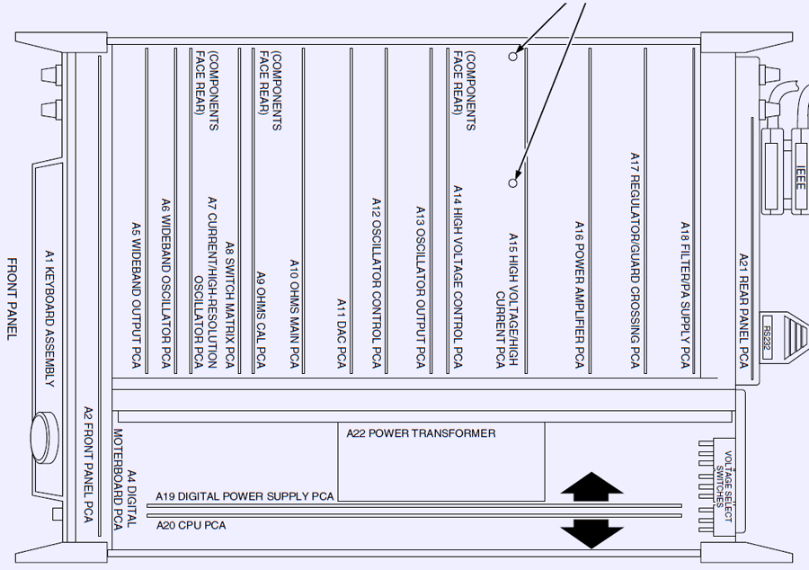
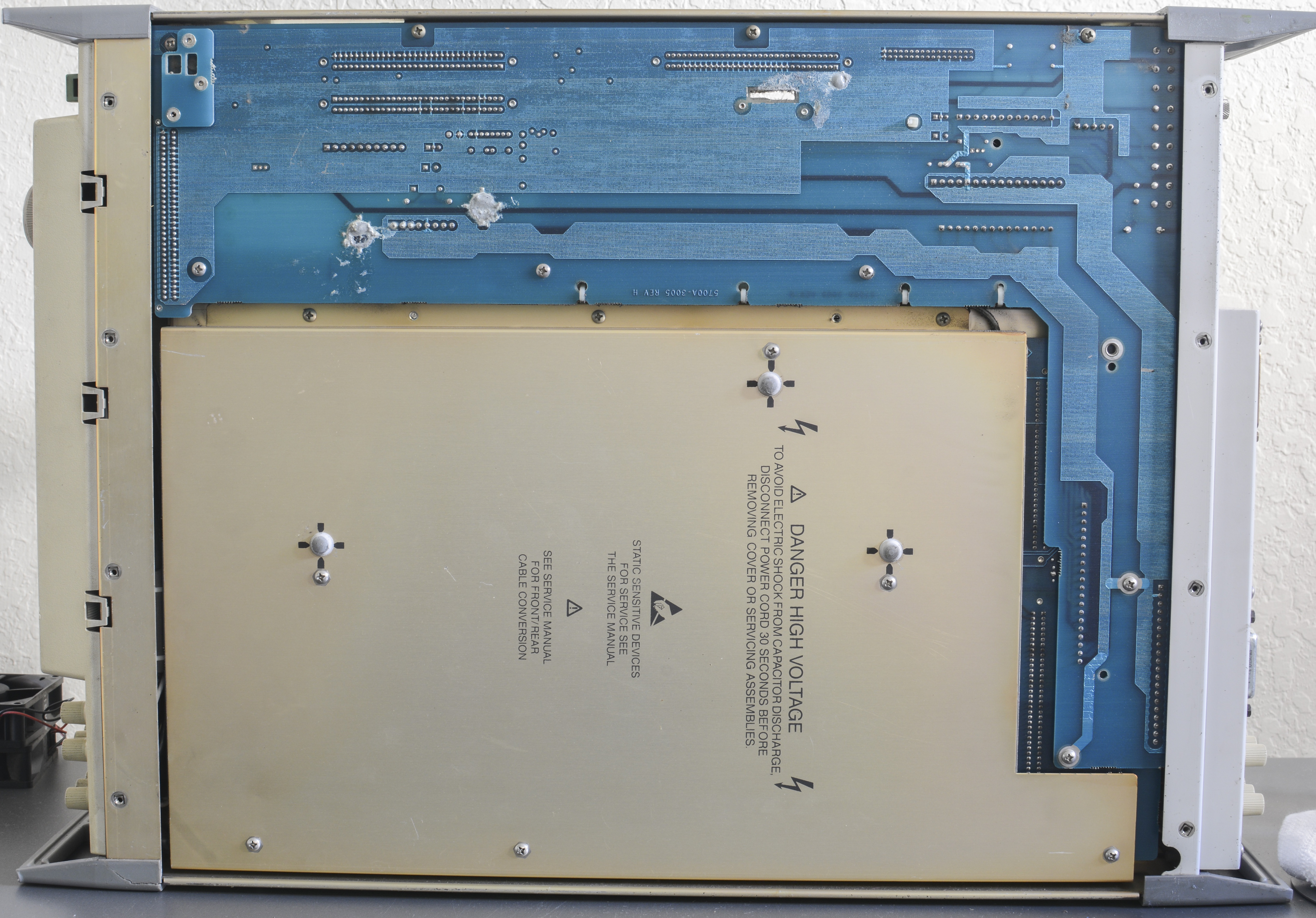
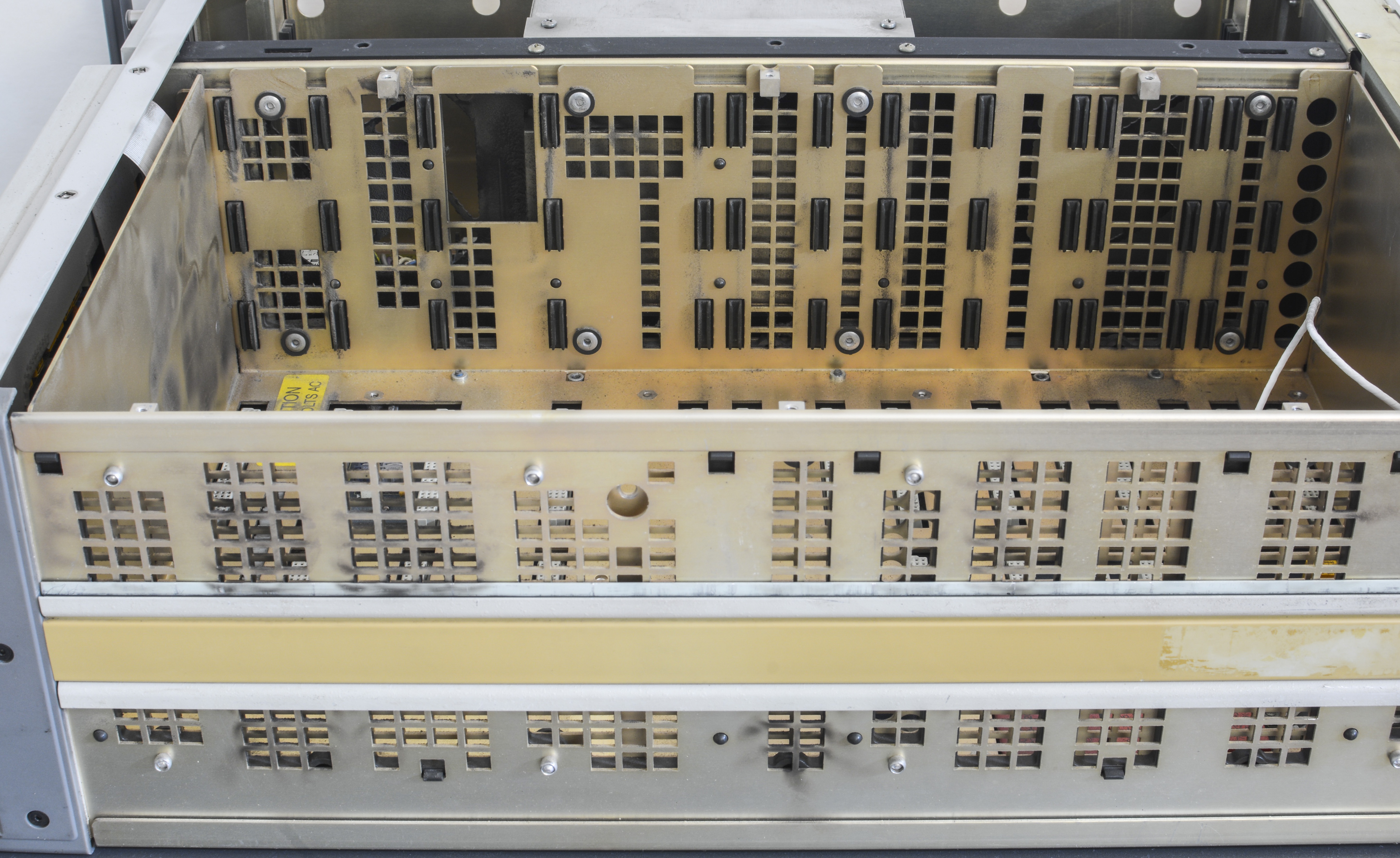
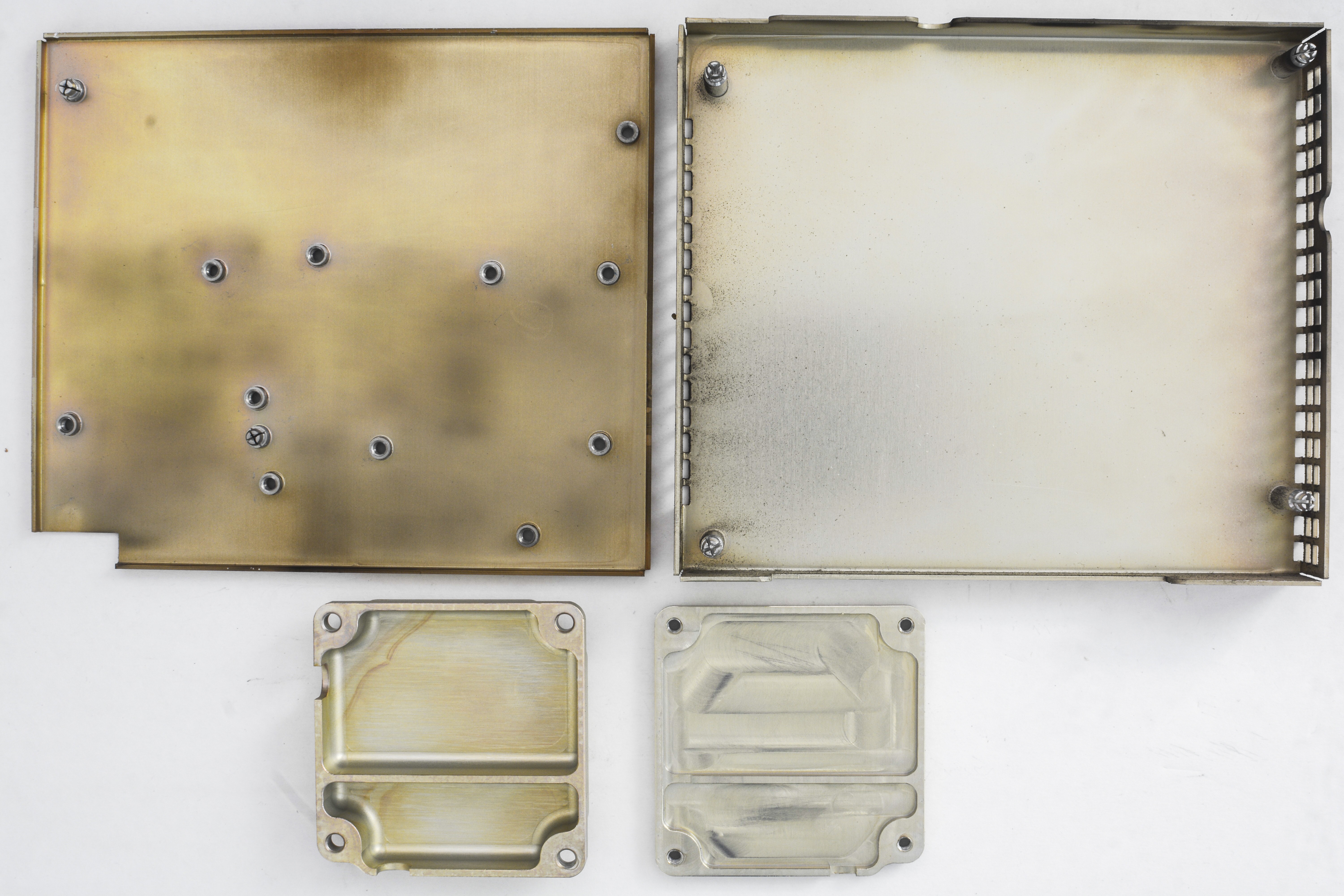
Time to remove the top cover. All internal modules and assemblies are further shielded and protected by solid metal frame parts with vent holes and openings for board levers.

Now we can see presence of A5 and A6 optional boards for wideband, so this calibrator does indeed have 5700A-03 option. Nice to have it, which allow ACV/ACI functions to be tested up to 30MHz. This is required for calibration of instruments such as Keithley 2001/2002.
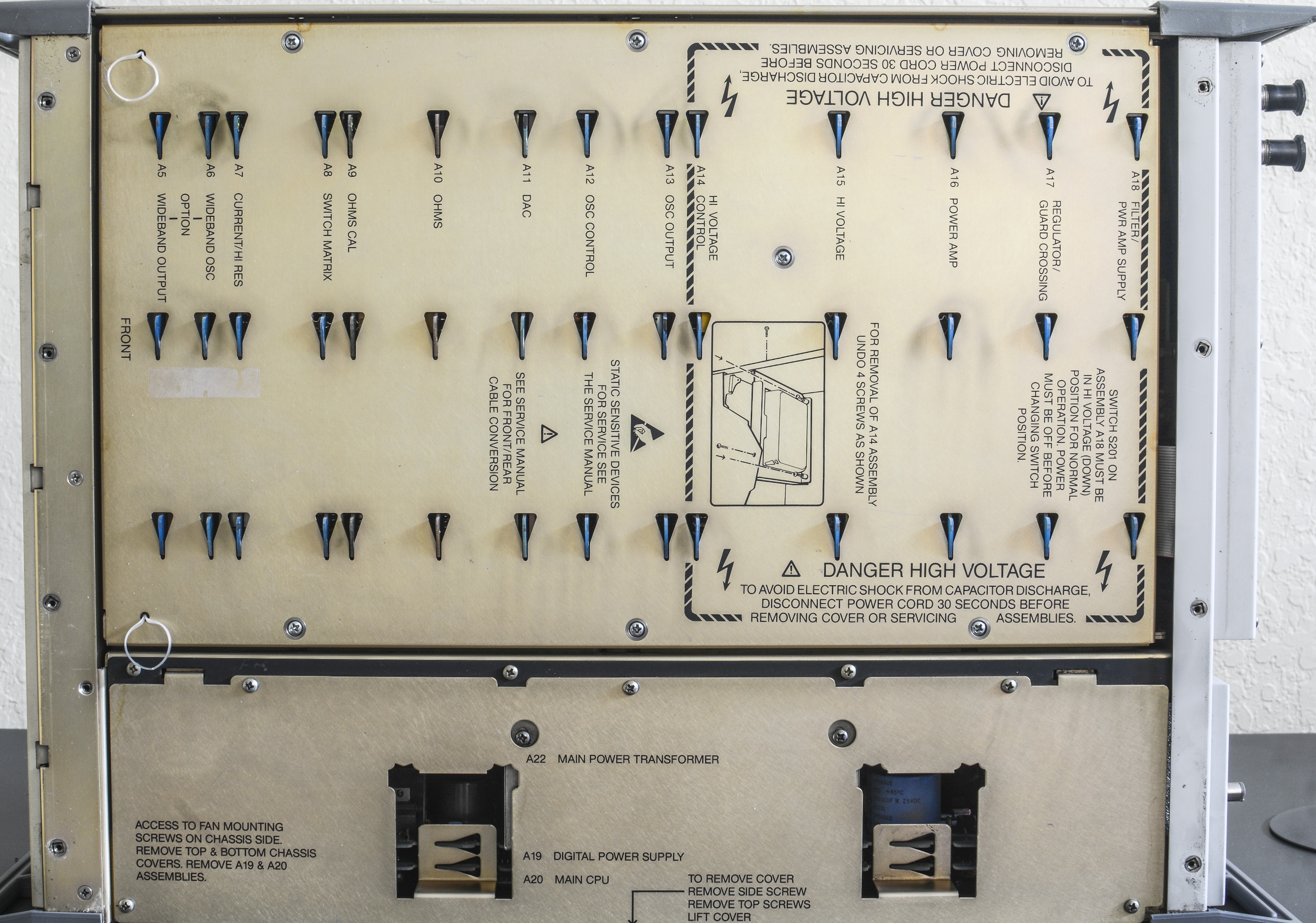
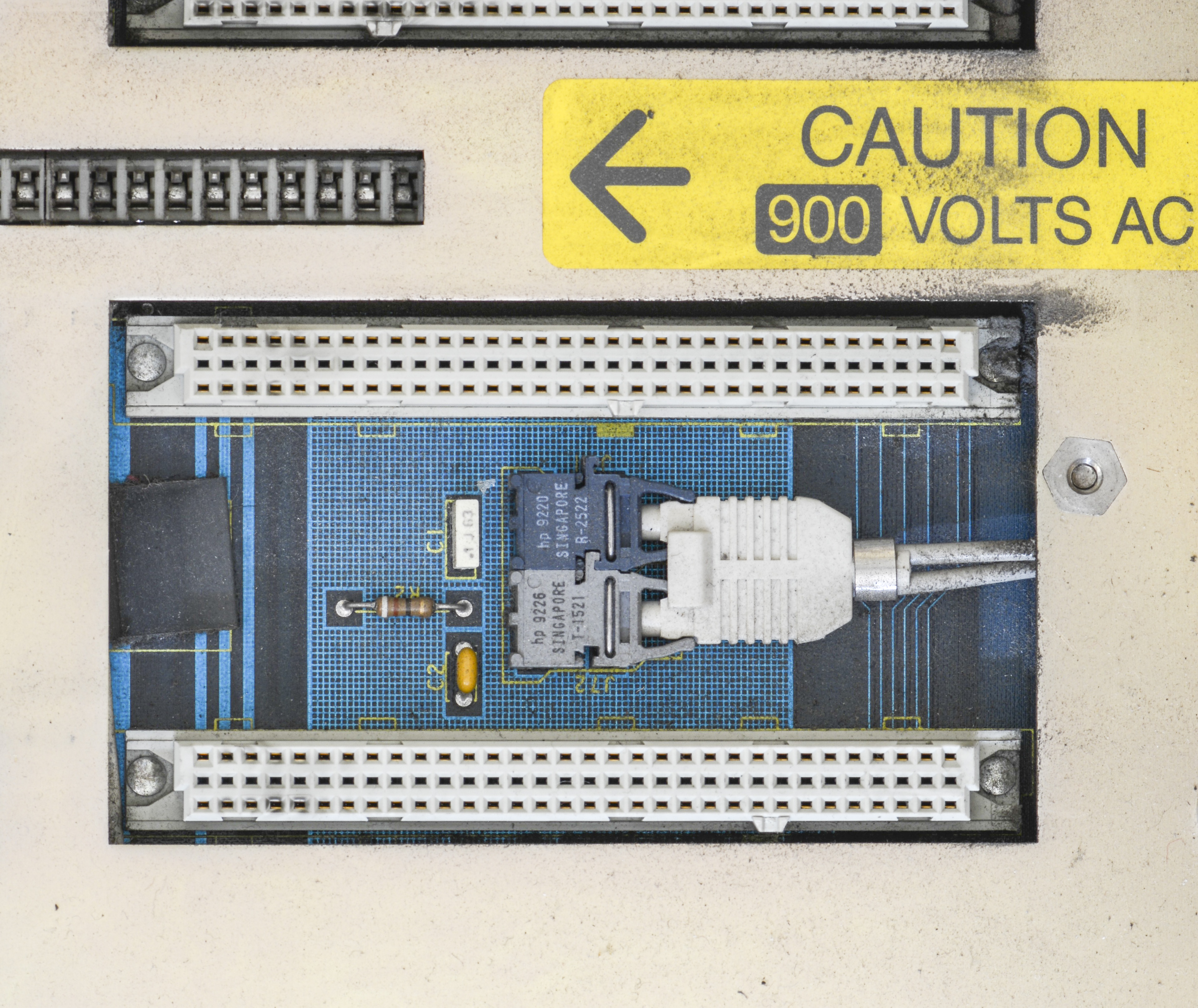
Look from the top reveal all boards presence and lot of warnings regarding dangerous high voltages presence and charged capacitor cautions. Let’s do same here in this article.
-1100 and +1100VDC voltages present inside of this calibrator when operation are dangerous and even lethal. Pay attention of what you are doing, and keep all connections stable and robust, not using hand probing unless absolutely required and safe. Use tools rated for CAT III operation while servicing high-power circuits in this instrument.
First we start with outguard section, boards A19 and A20. All modules will be covered in detail below, using dedicated sections.
Exposed now base board is all covered with dust and dirt, and urges for intensive dry air cleaning and careful inspection.
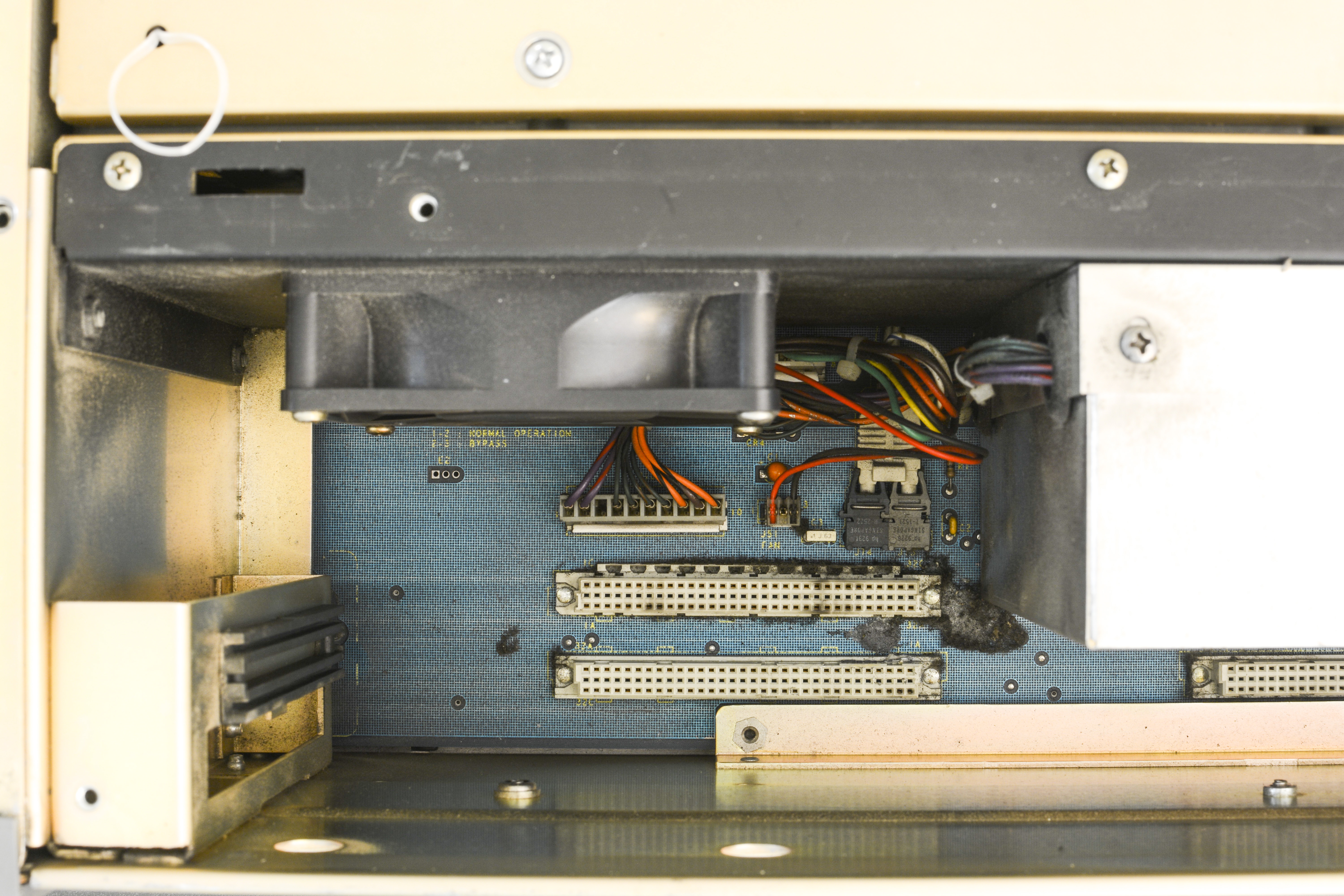
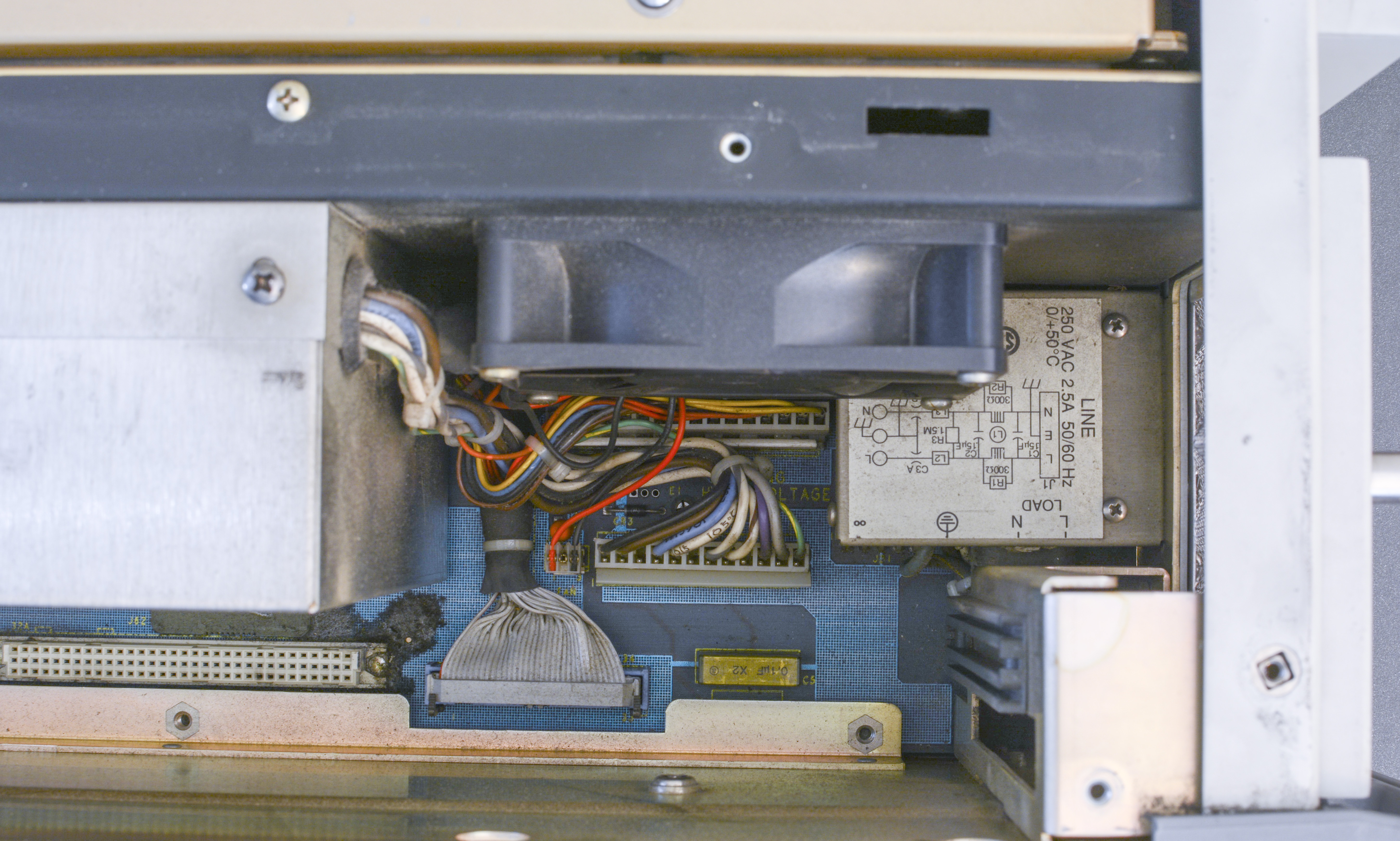
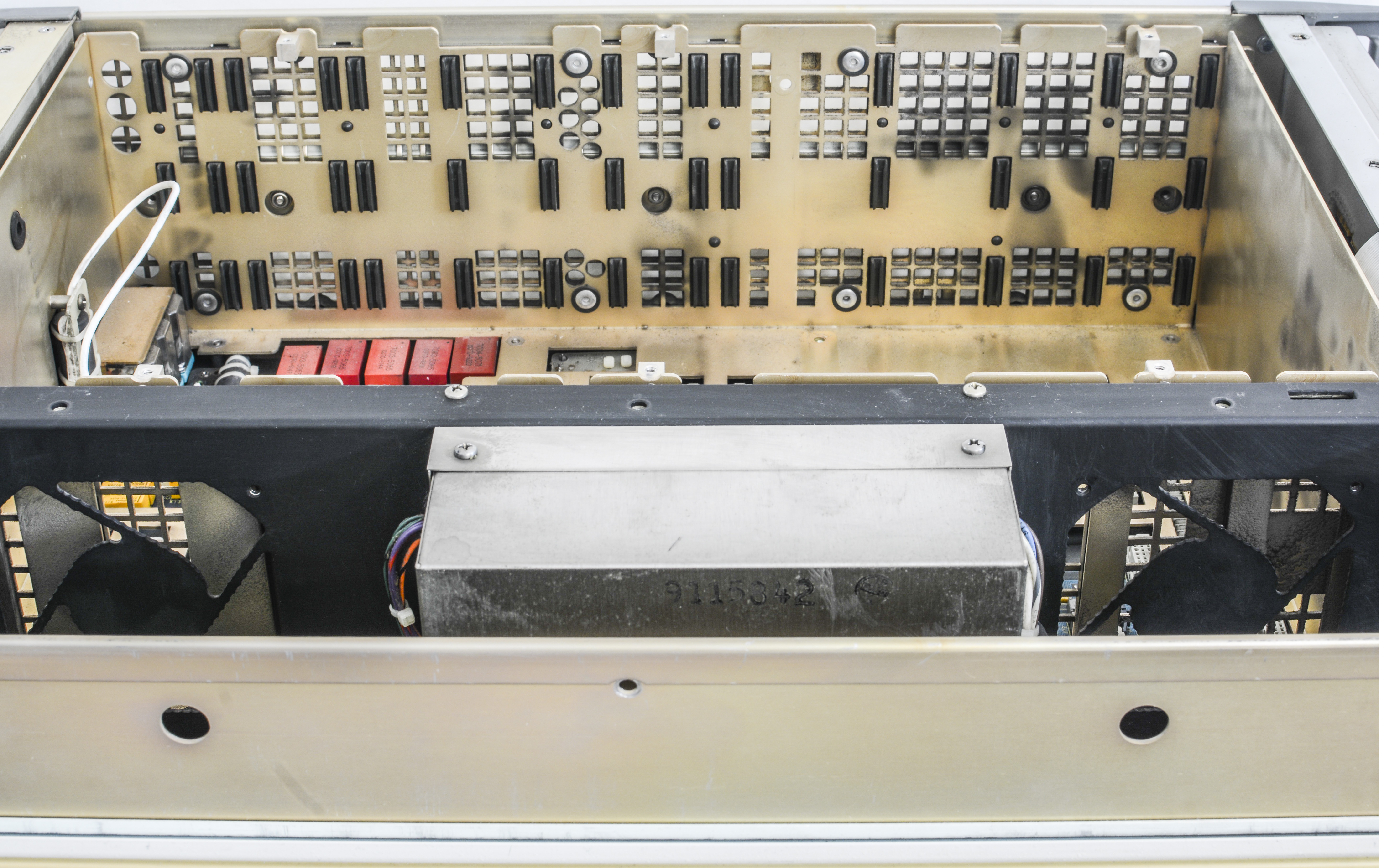
Middle shielded can contain mains primary transformer A22, custom made for Fluke. This power unit together with A19 PCB powers whole box. You can see pair of 80×80 mm DC fans mounted on the side. There are dual HP (today Avago) Versa-link transmitters to inguard domain. This is very same optical isolation technique used in HP 3458A.
Extensive cleaning will be performed on chassis parts. DC FANs are ok, but not top tier brand, like was expected. Might change them in later.

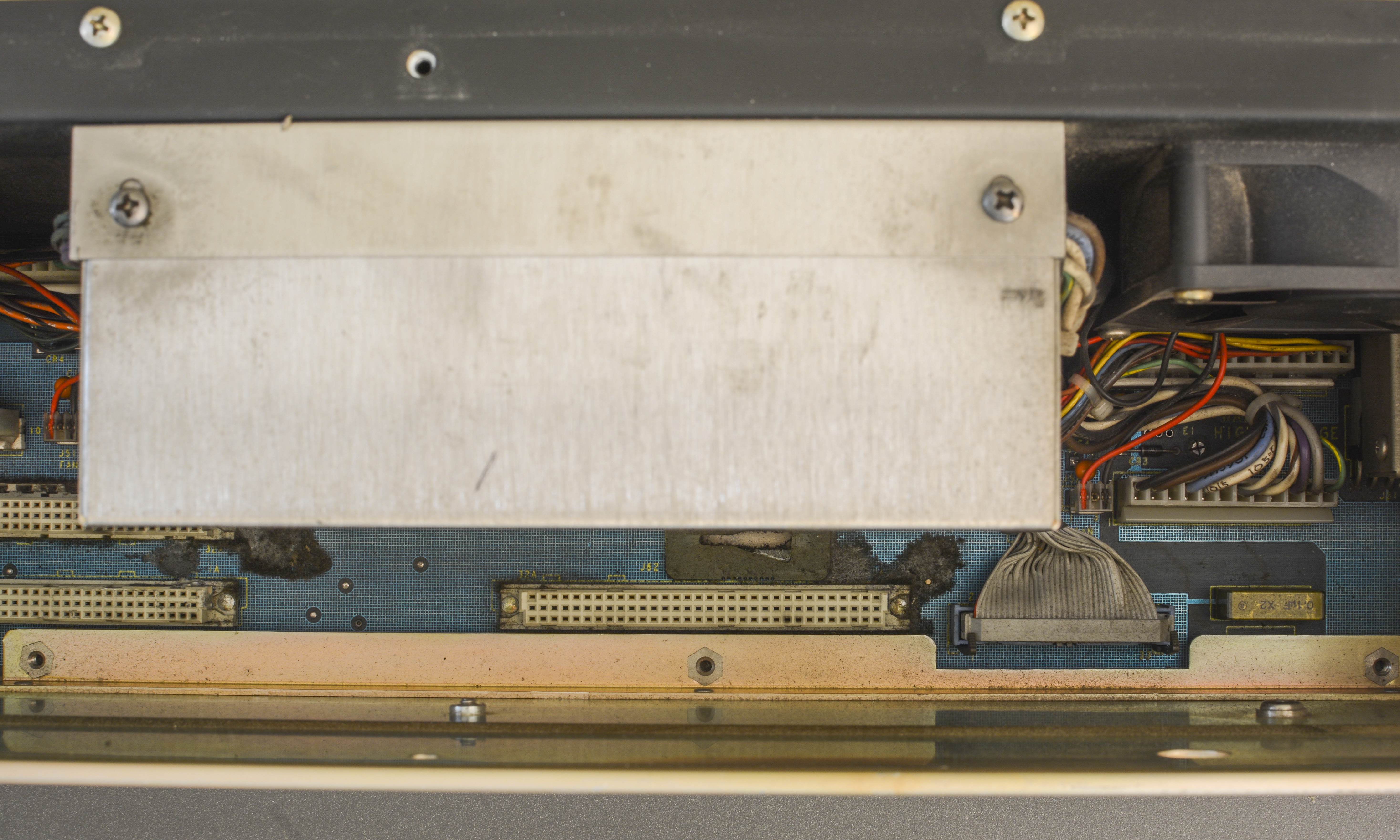
Time to look into inguard area, with all boards and modules removed.
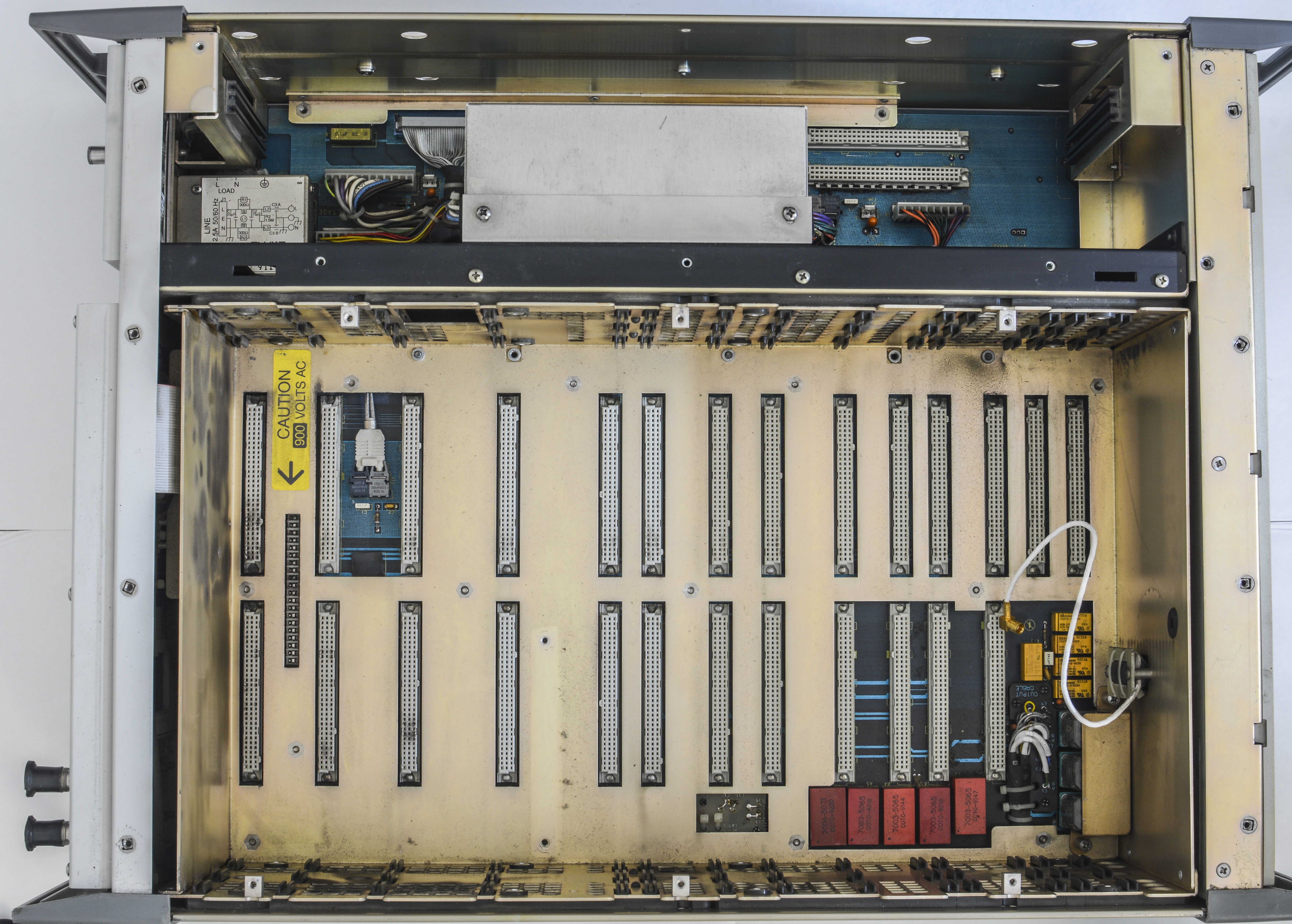

Check that relay love with own shield cover and dedicated cutouts in the frame. Wideband option SMB cable to N-type connector going thru filter choke to supress EMI.


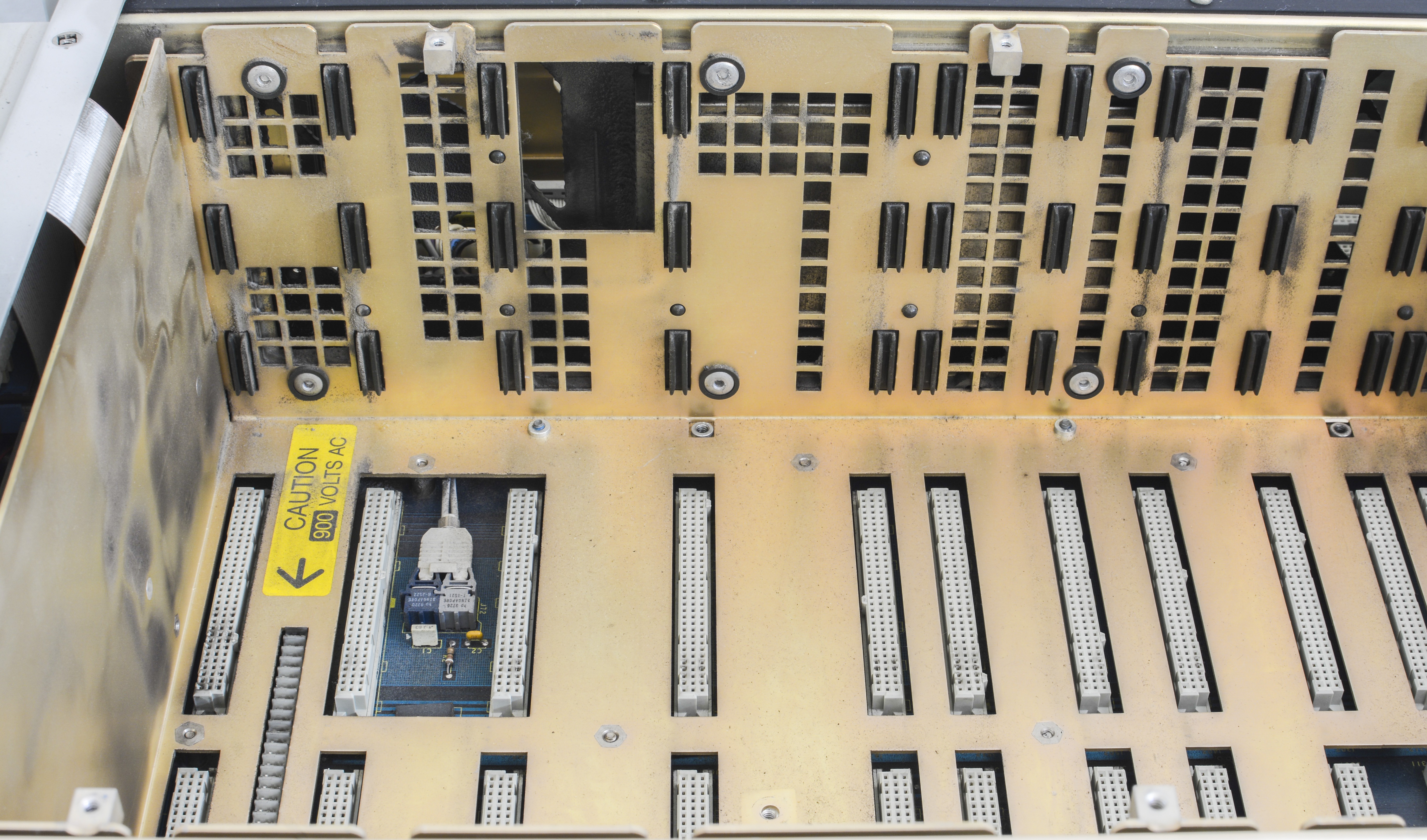
Optoisolated interface to digital brains on A22 board.
A1 Keyboard PCA (Fluke P/N 761049)
A2 Front panel PCA (Fluke P/N 761031)
Interesting section in service manual covers on page 289 regarding non-uniform pixels brightness on VFD, which usually happen after static image displayed for long time. According to manual, this effect can be reversed and cleared up by lighting up the whole display and leaving it on overnight. To enable all segments, next procedure suggested: Enter Setup Menus, select Self Test & Diags, 5700 Self Diags > Front Panel Tests > Display/Control > All On.
Left VFD display with segment digital section is very bright, like new, which is great news, as new front panel PCA cost few K$! Graphical dot-matrix VFD on the right is dimmer, and have some visible ghosting:
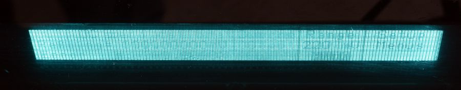
I’ll run recommended above procedure to see if it improves.
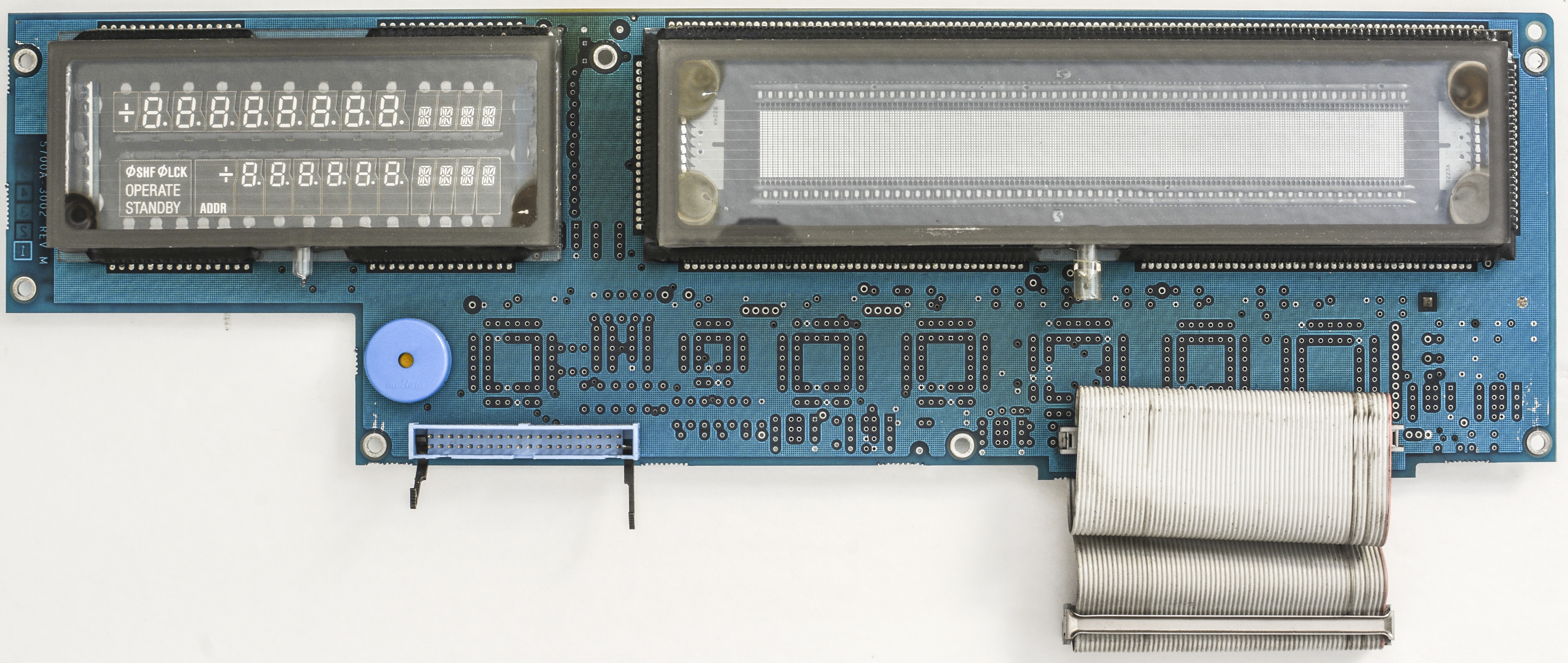

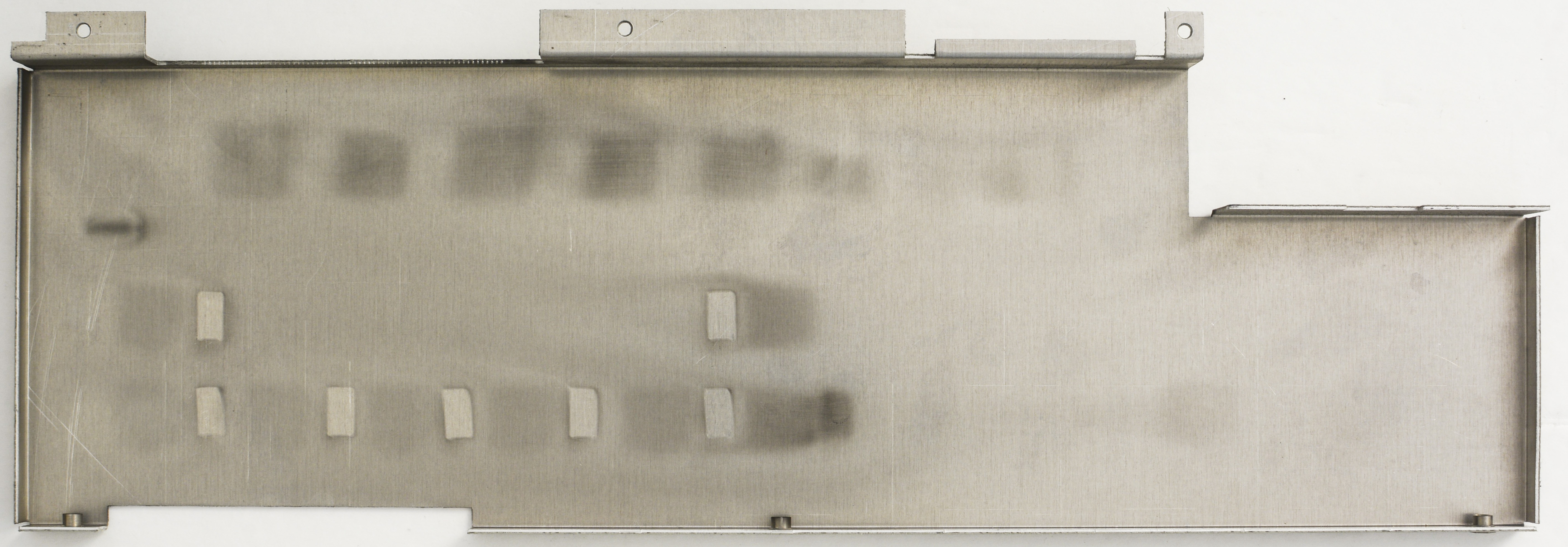
Front panel is solid metal frame behind plastic cover and keyboard with opening just for displays.

All terminals are beryllum copper, as expected for instrument capable of sourcing precision DC voltages.
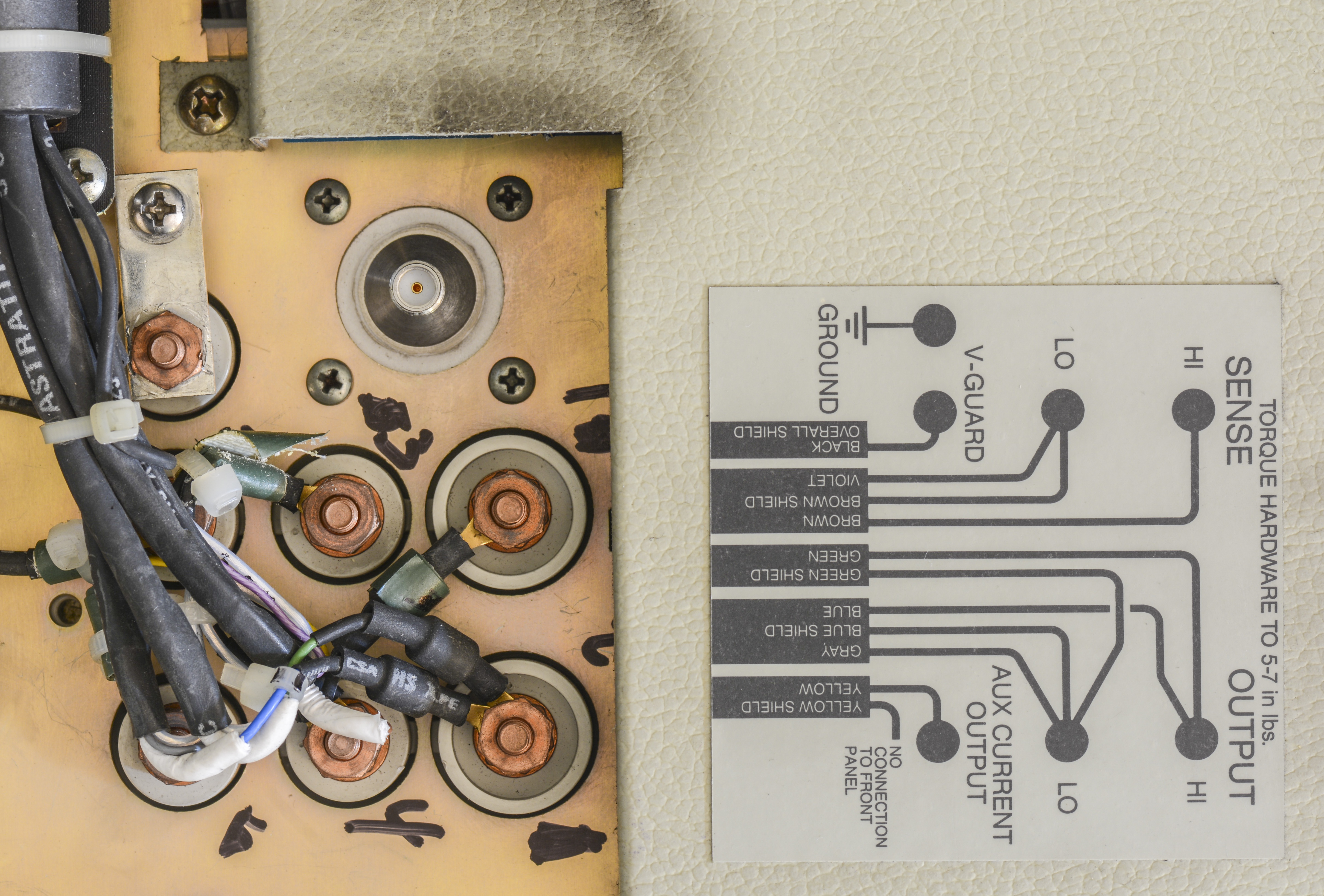
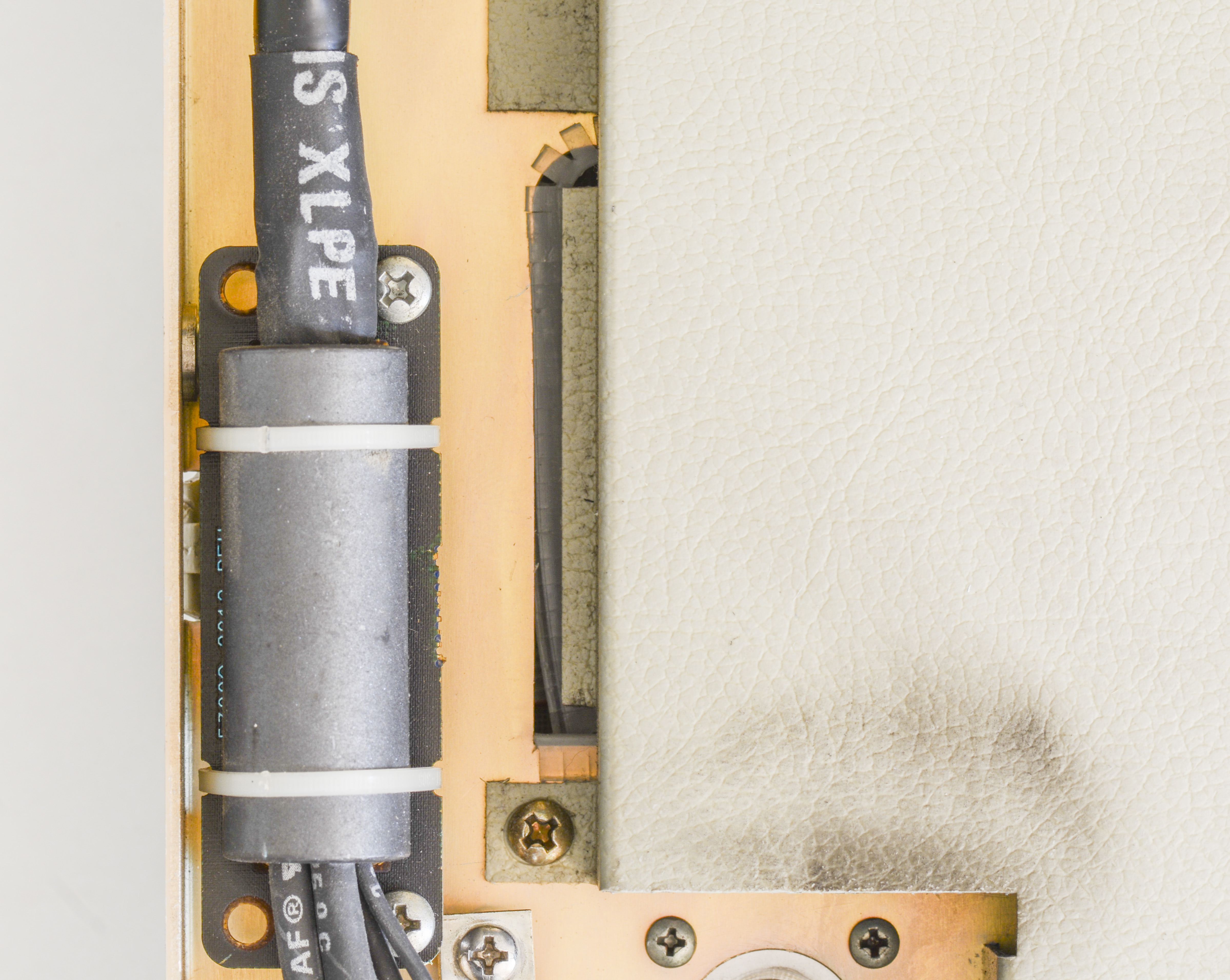
Front panel board is further shielded by solid metal cover.
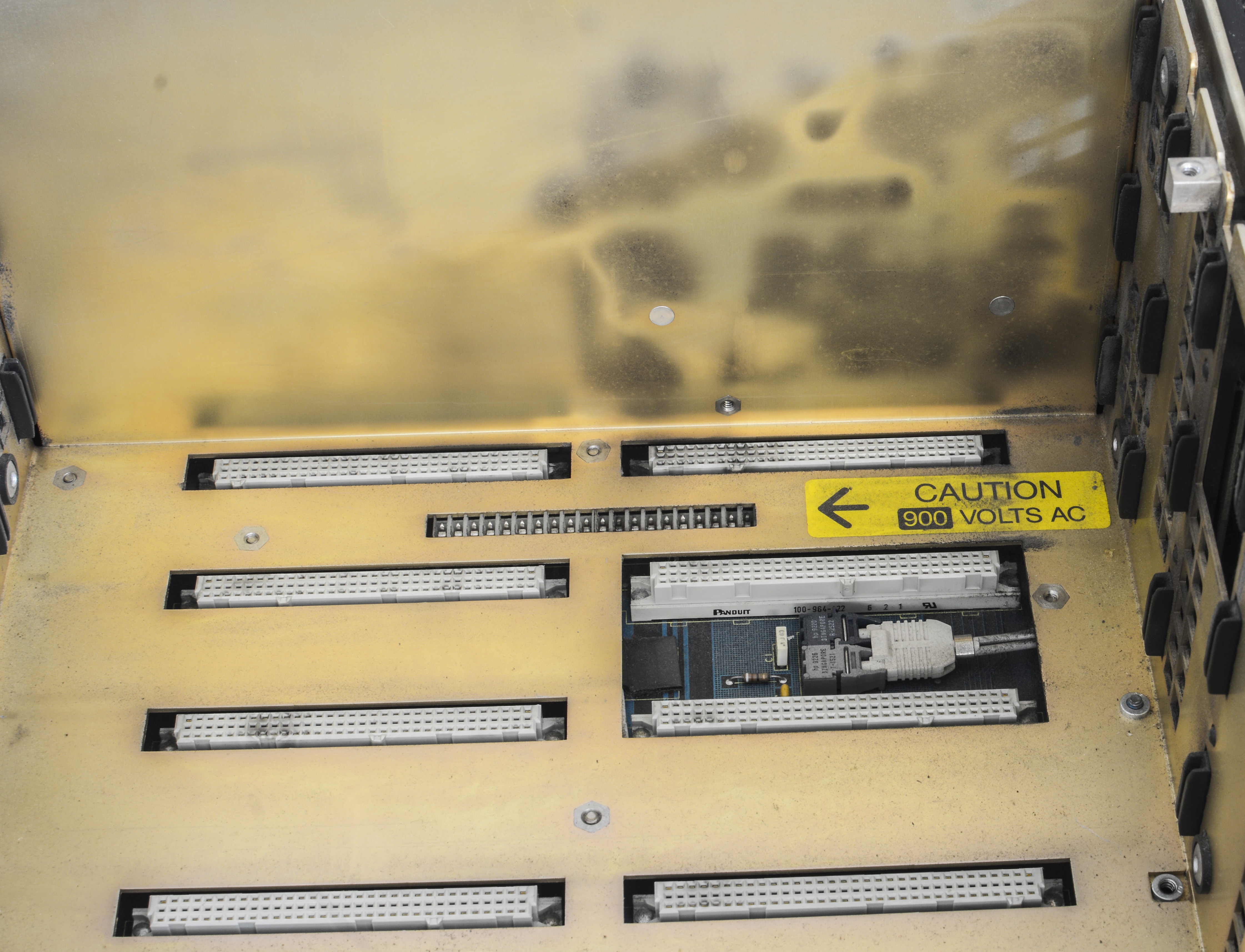
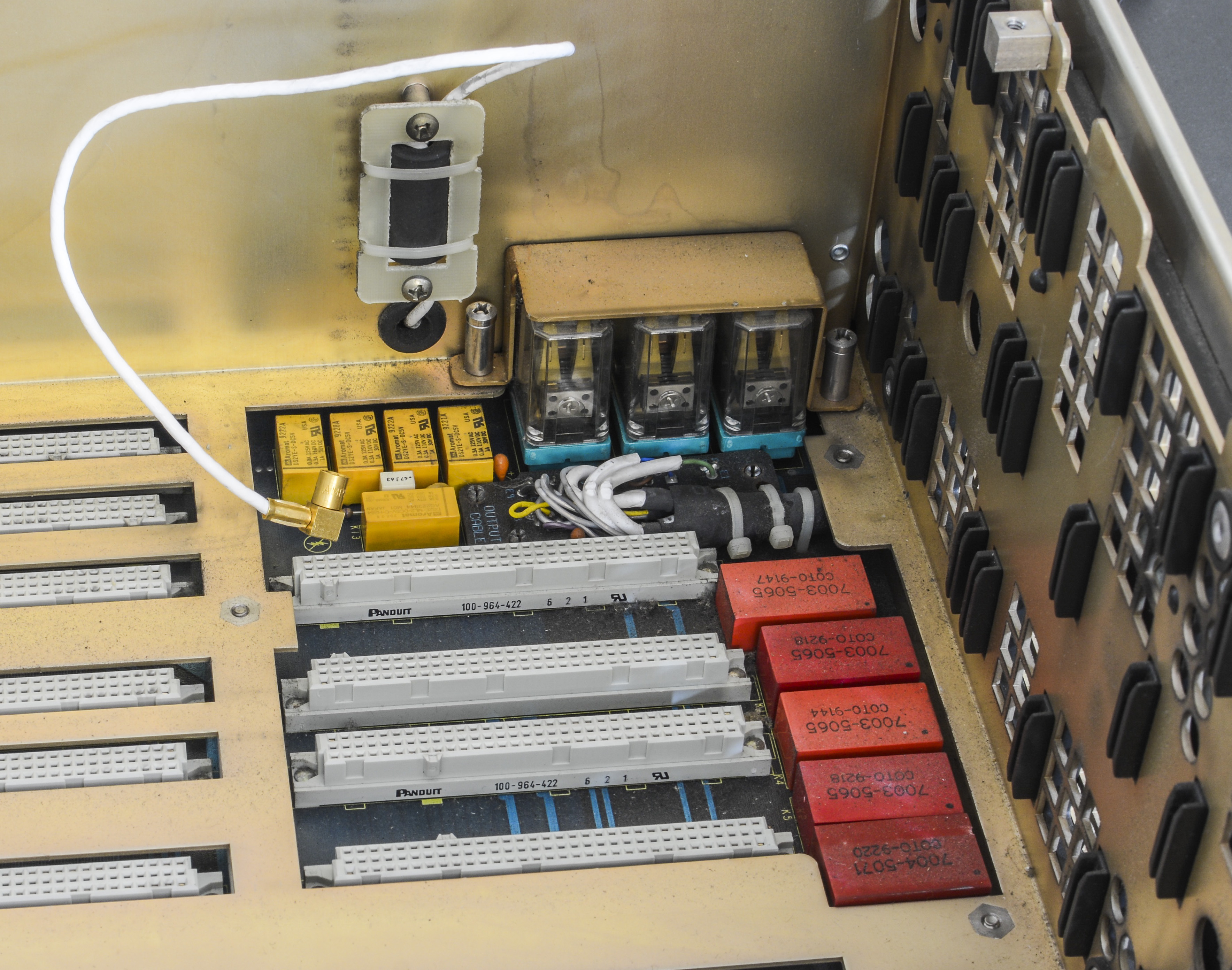
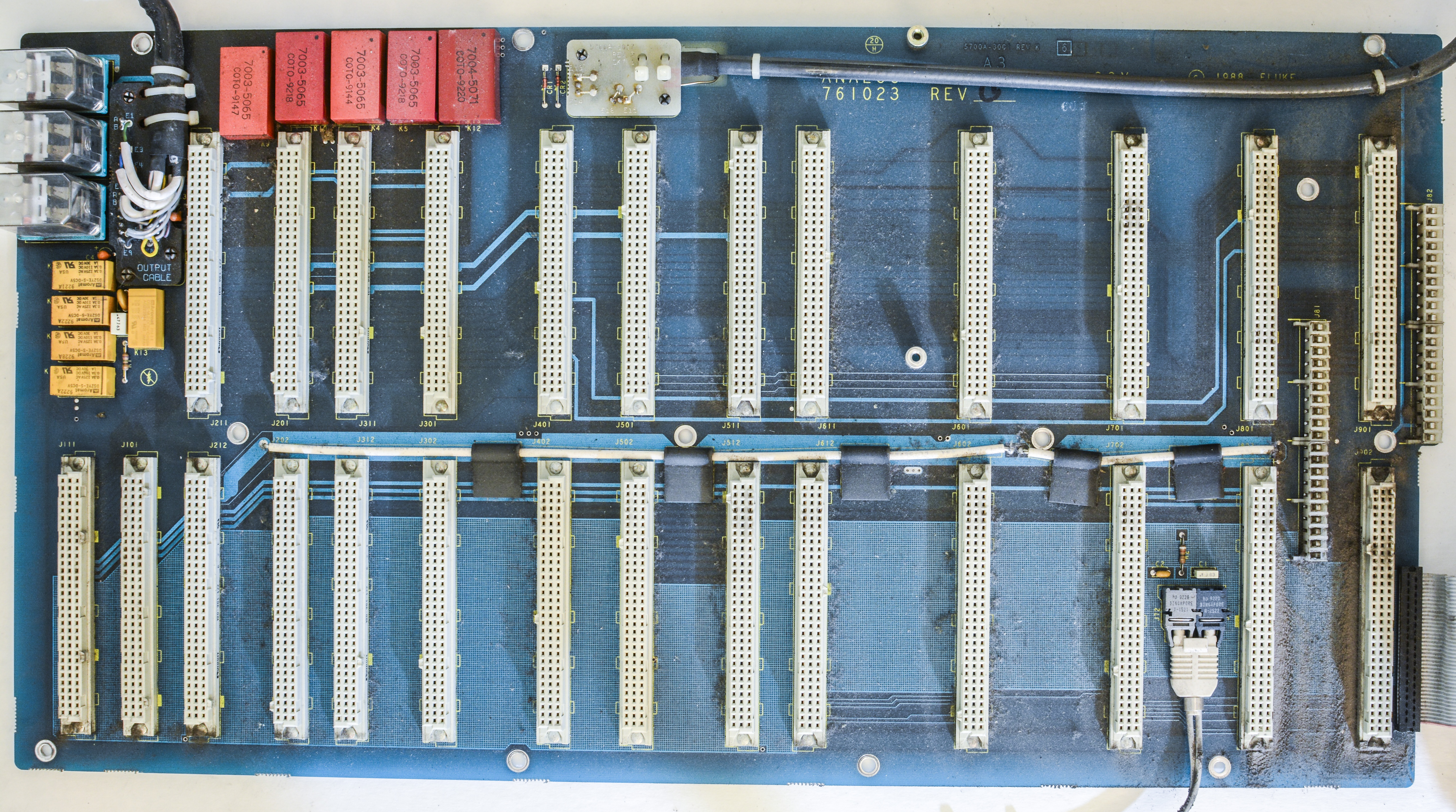
A3 ANALOG Motherboard PCA (Fluke P/N 761023)
This board just have interconnects for all modular PCBs and some switching COTO relays and optical isolation interface for inguard side.
A4 DIGITAL Motherboard PCA (Fluke P/N 760942)
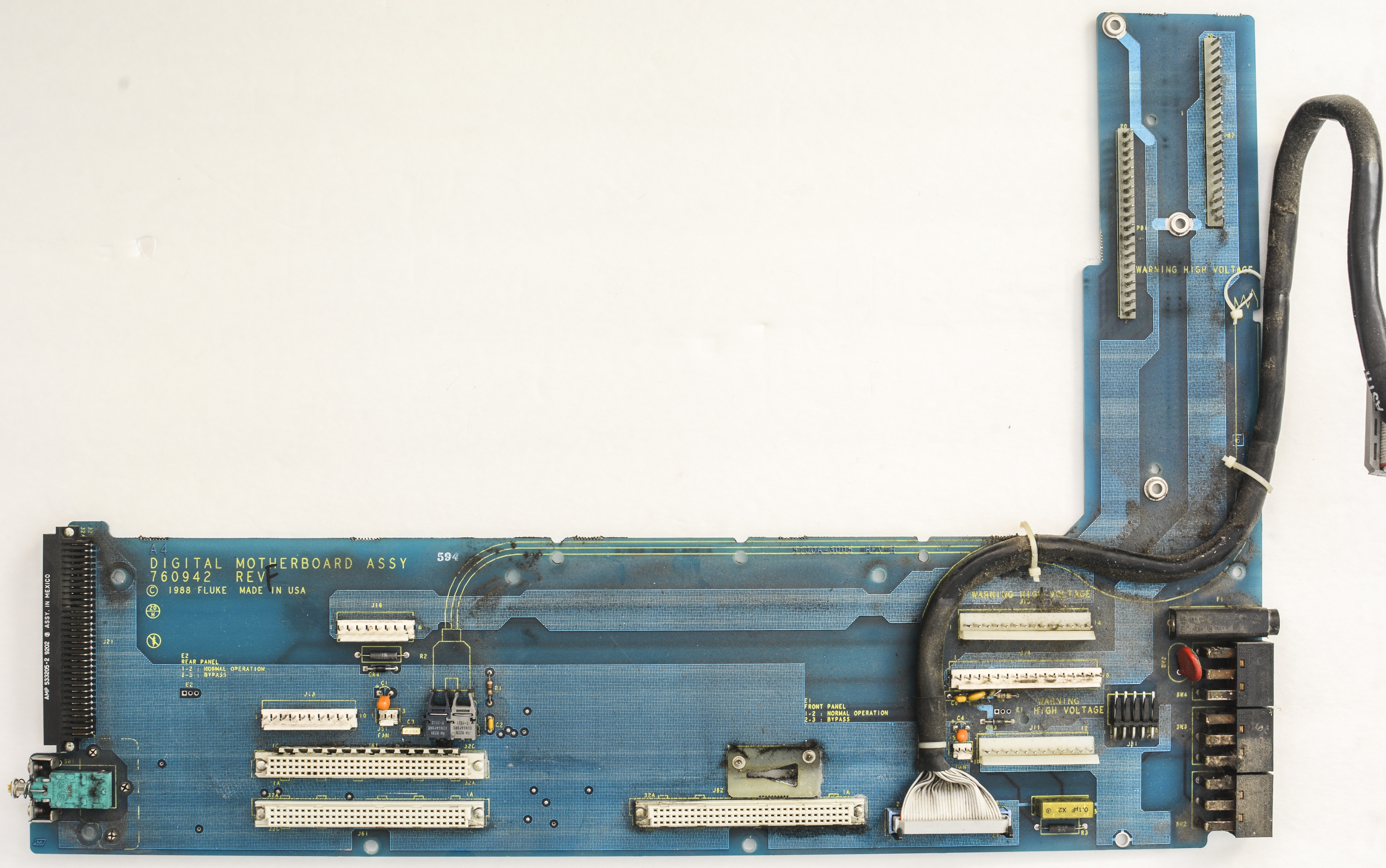
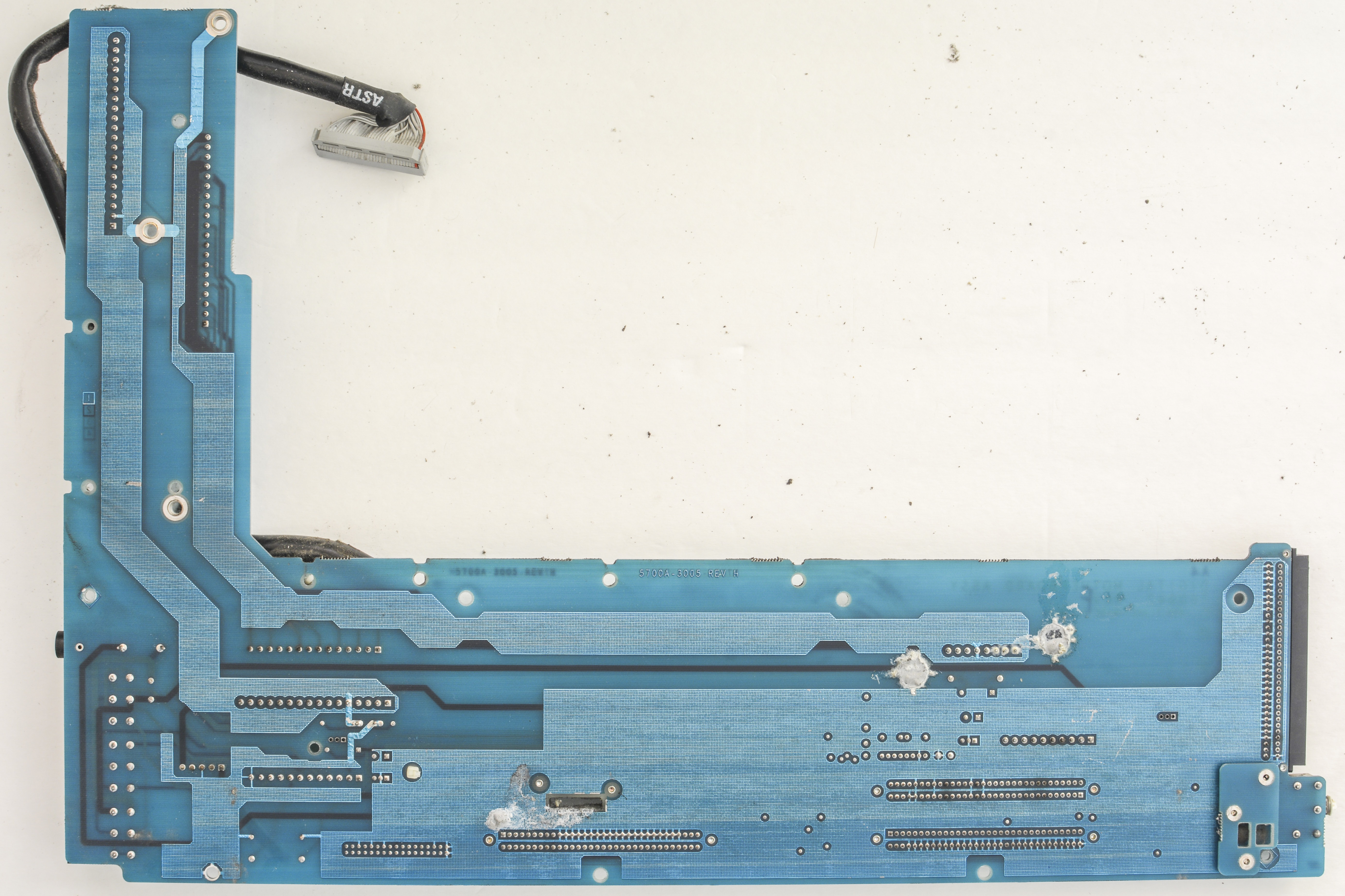
Interconnects for digital earth-referenced side of calibrator. It also feature connectors to transformer and mains input voltage selector switches.
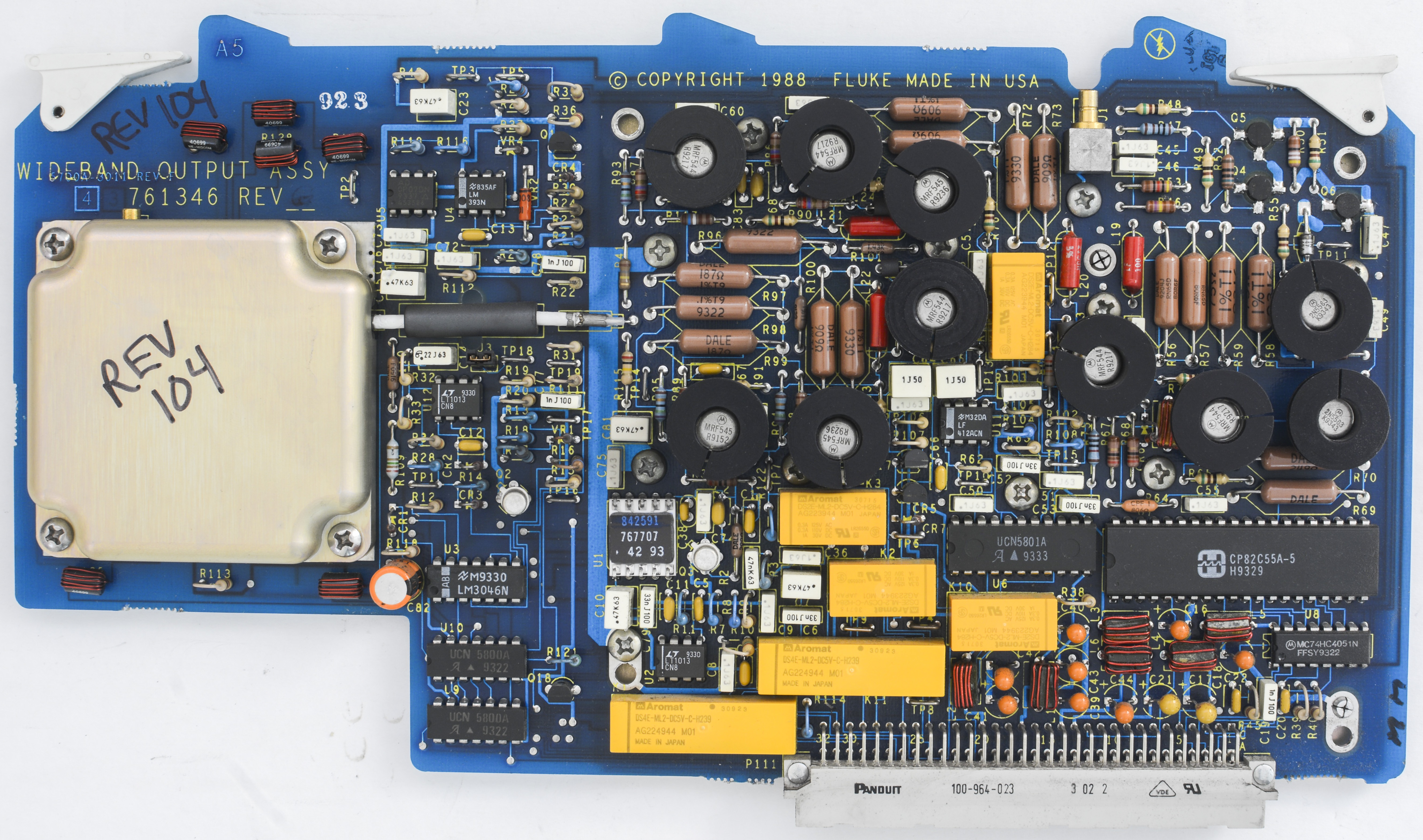
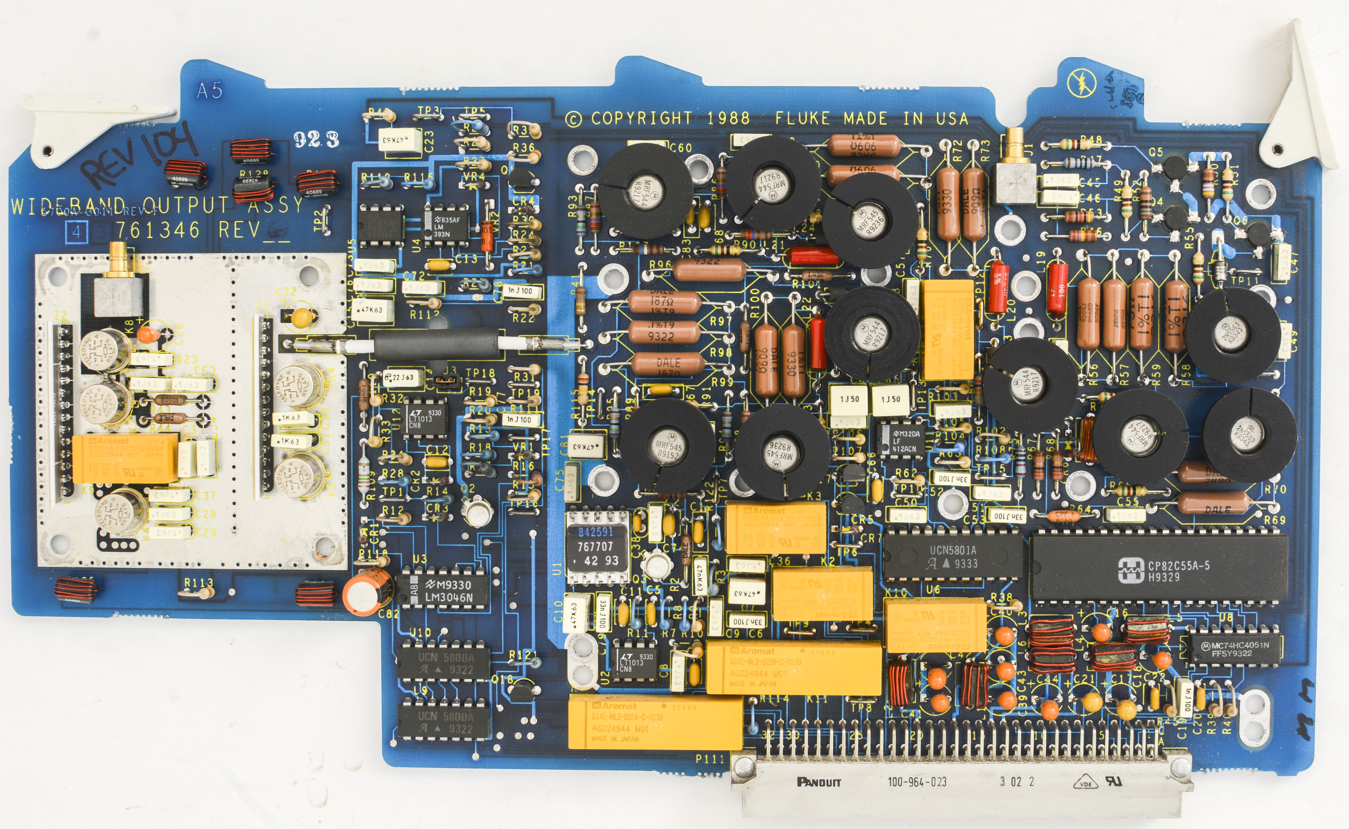
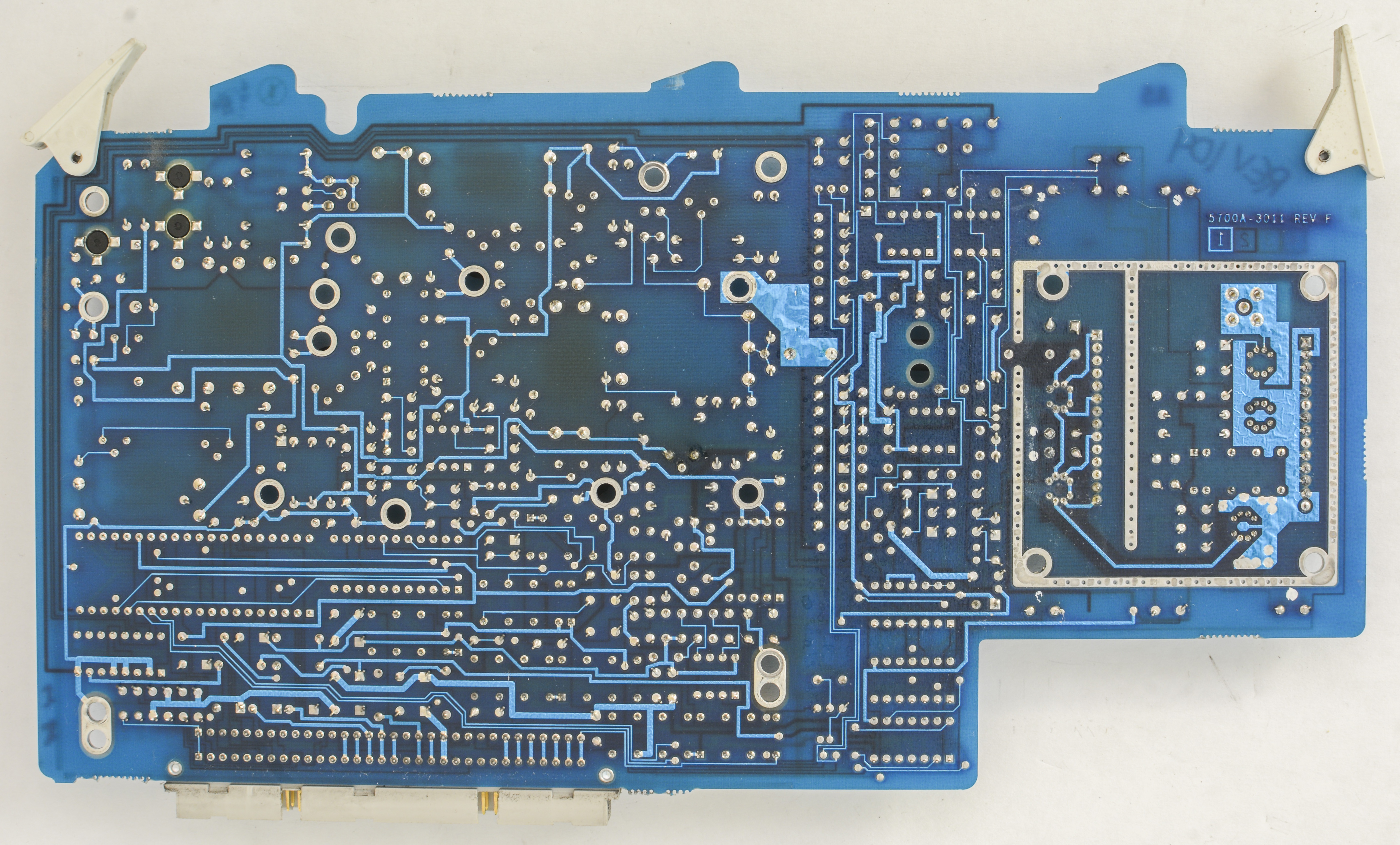
A5 Wideband output PCA (Only on 5700A-03)

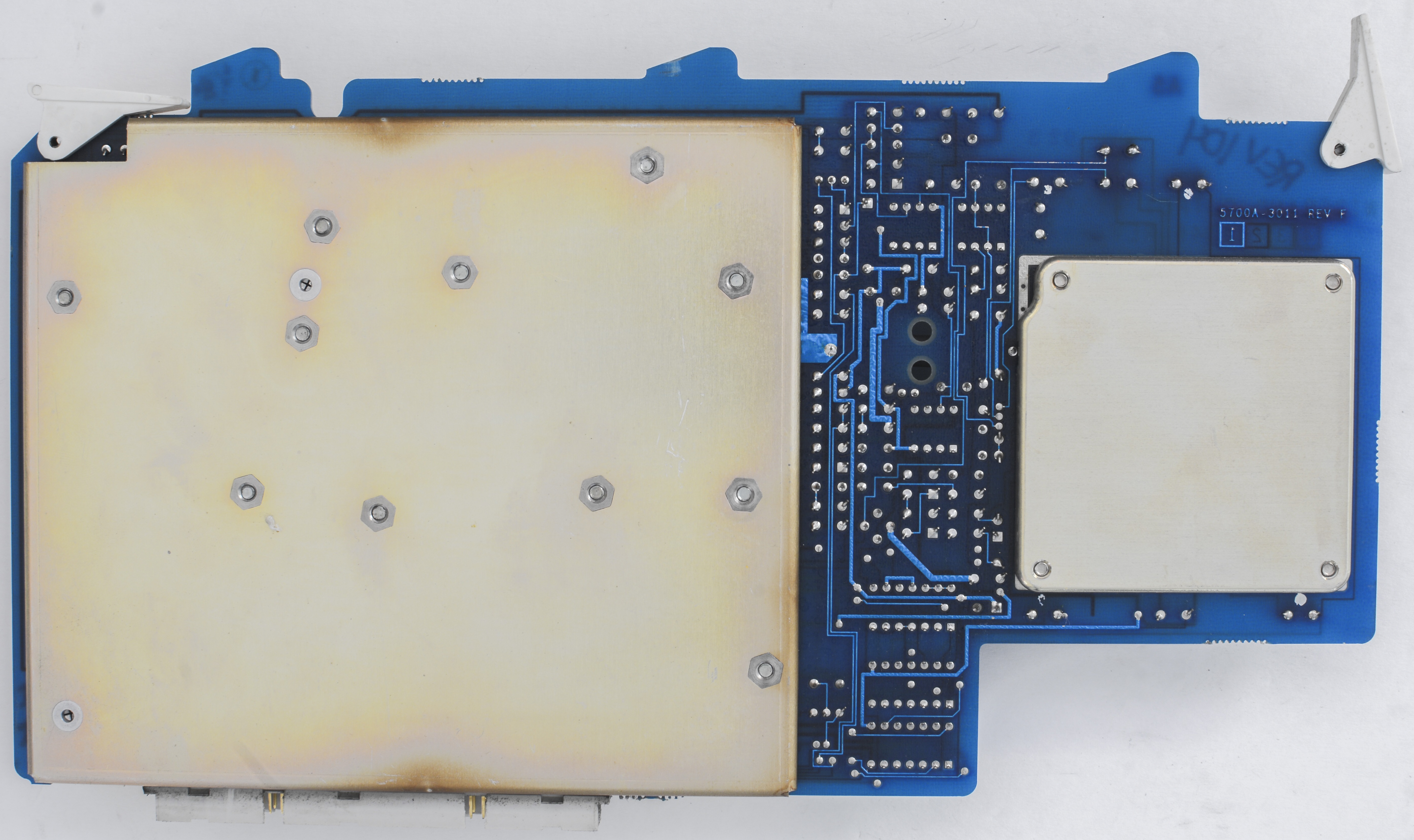

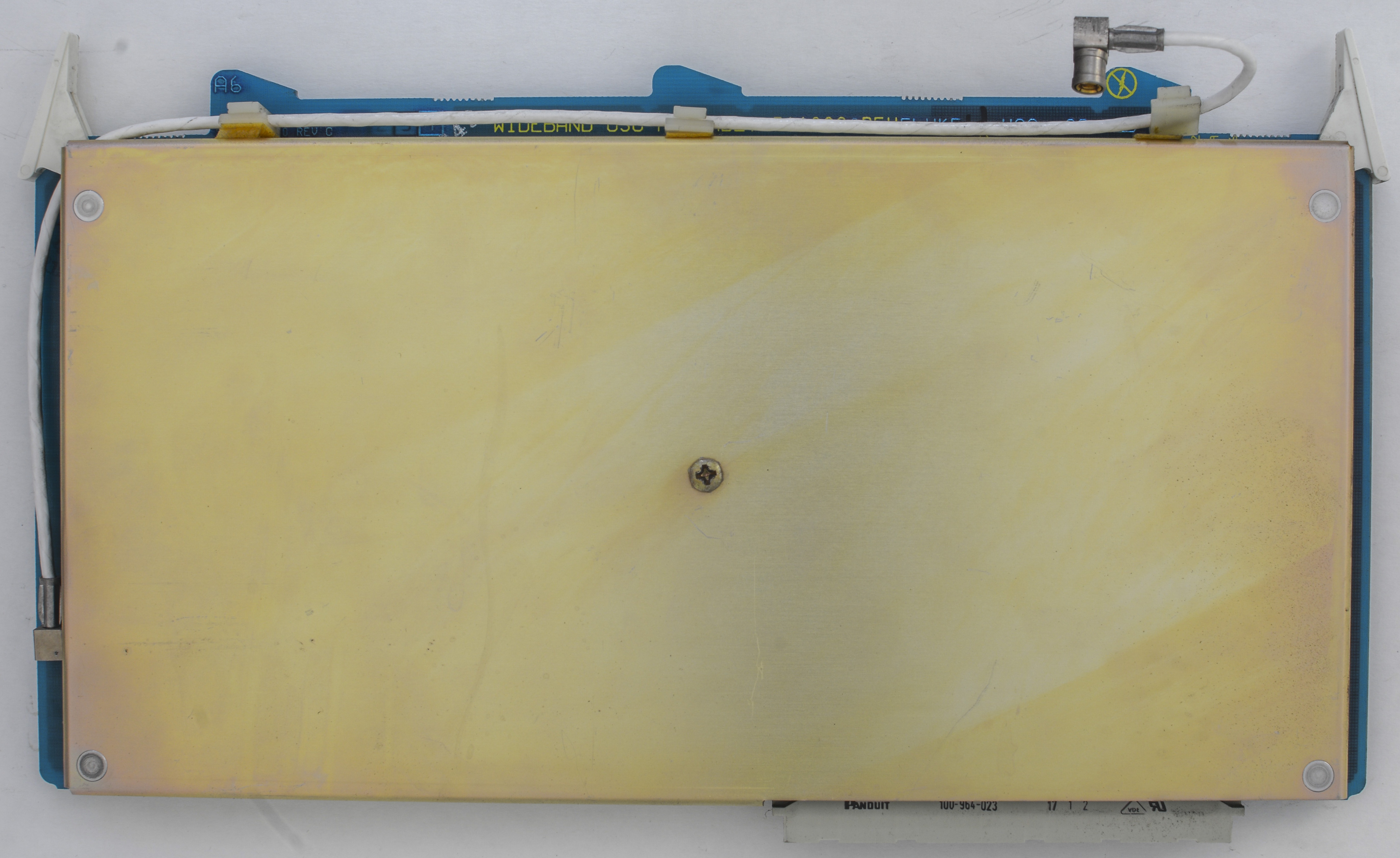
A6 Wideband oscillator PCA (Only on 5700A-03)


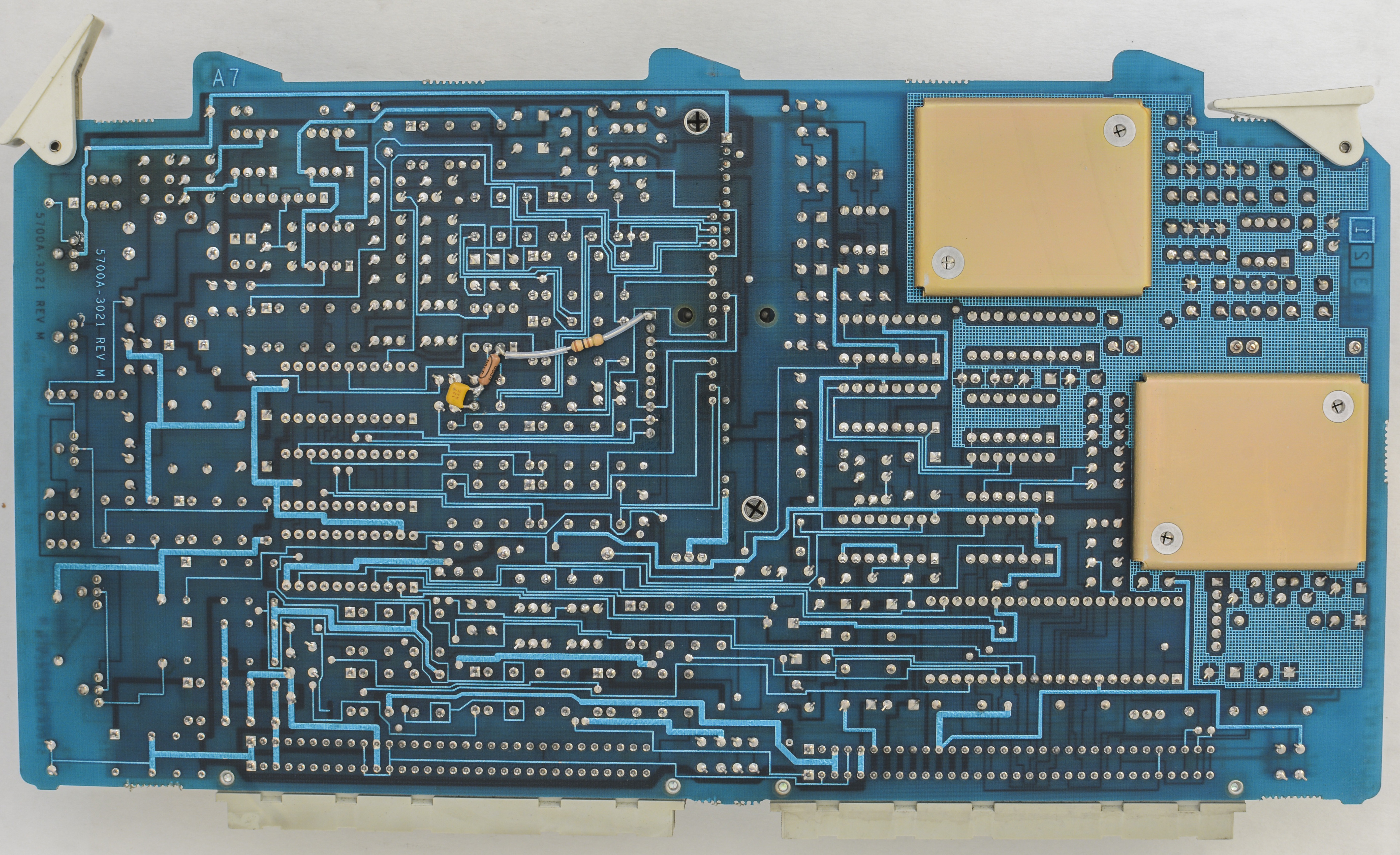
A7 Current/High resolution oscillator PCA (Fluke P/N 764613)


A8 Switch matrix PCA (Fluke P/N761106)
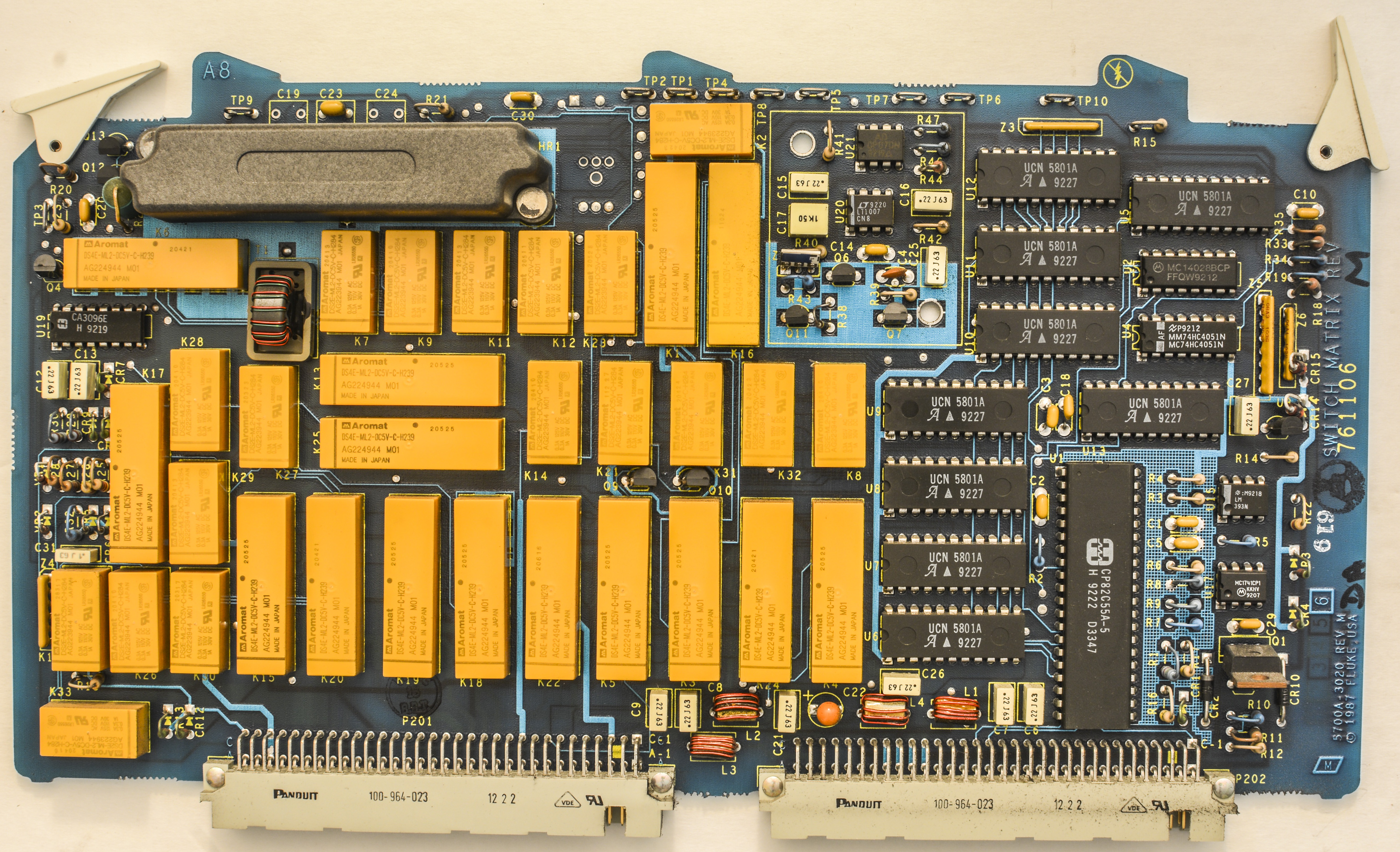
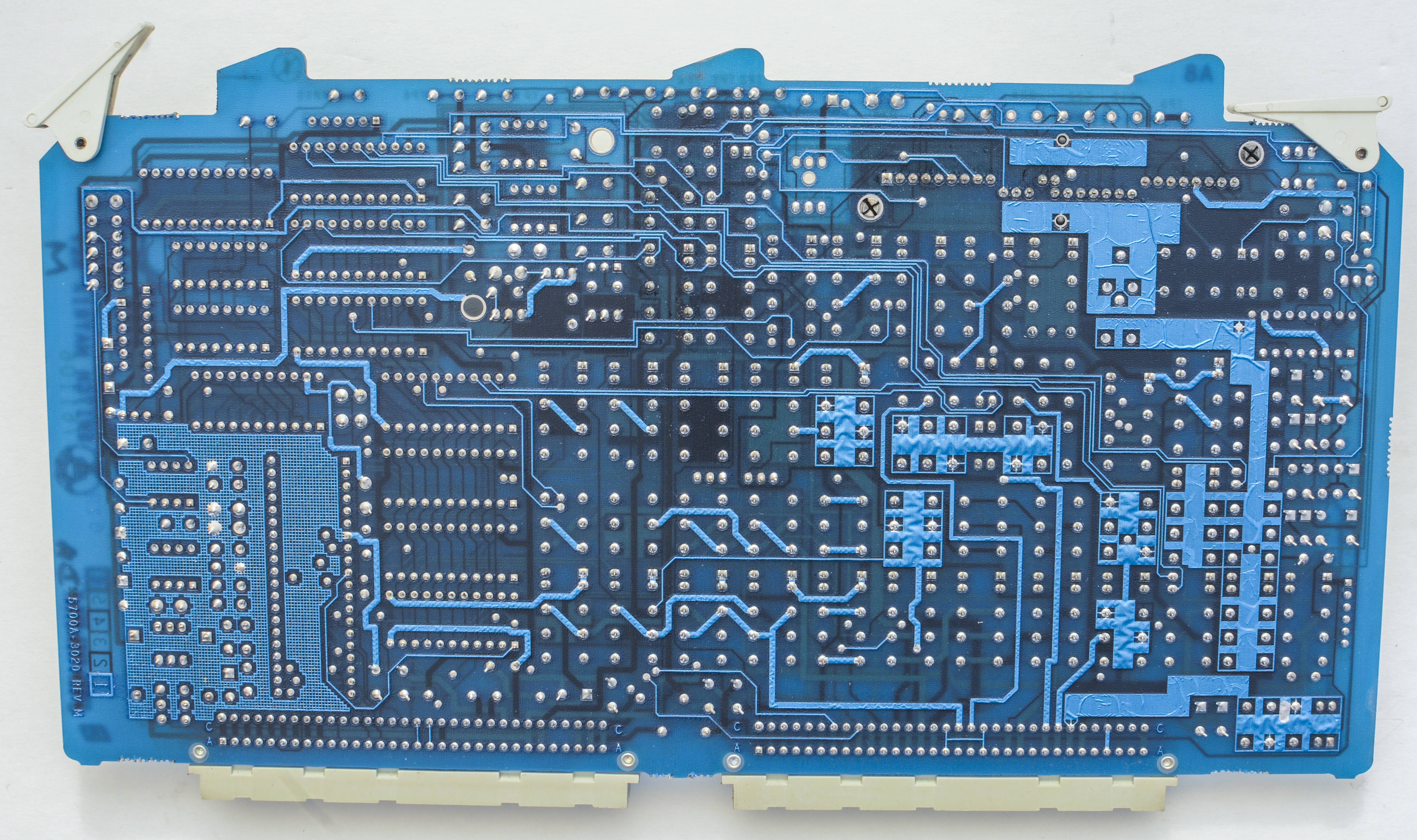
This board have many relays.
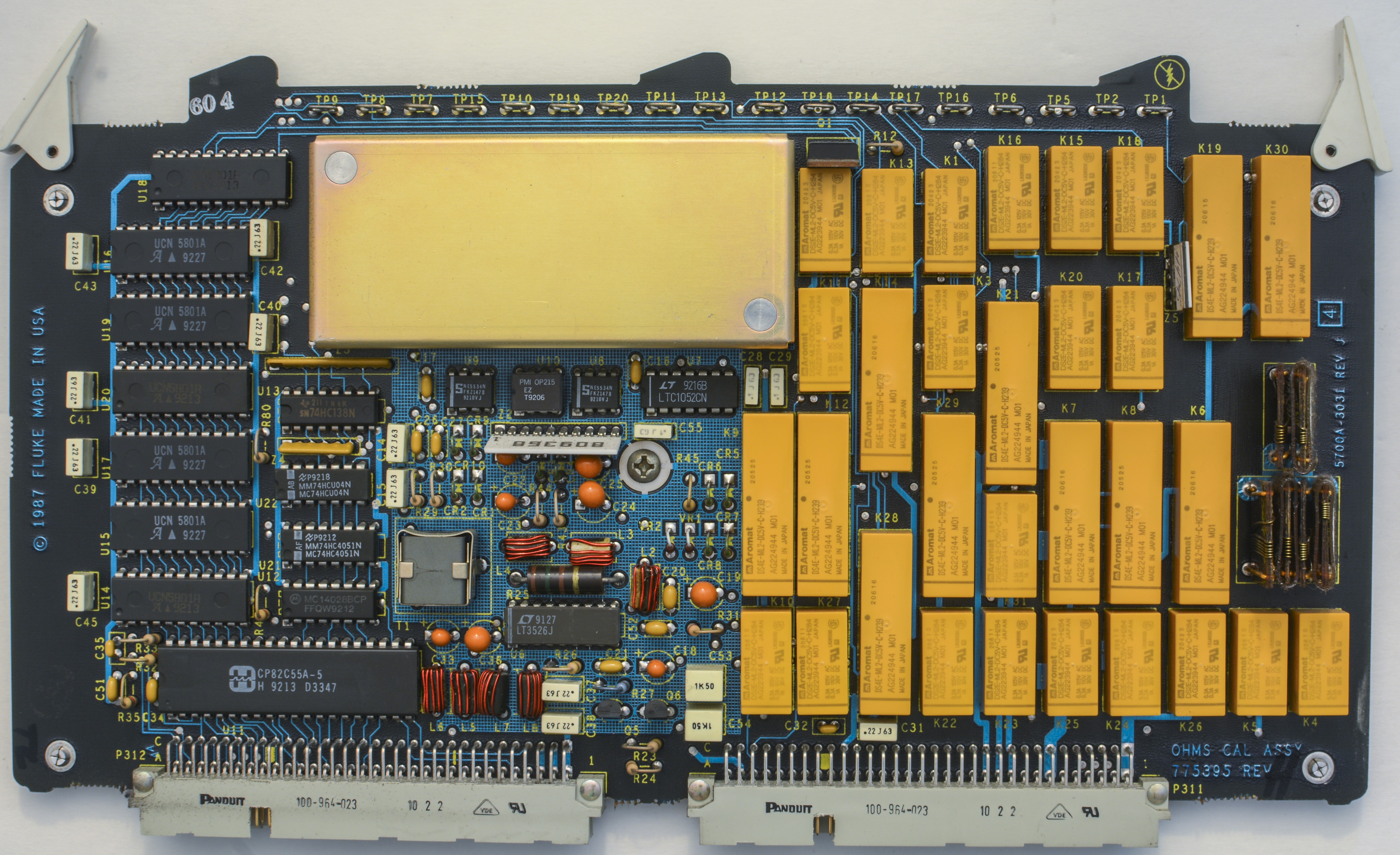
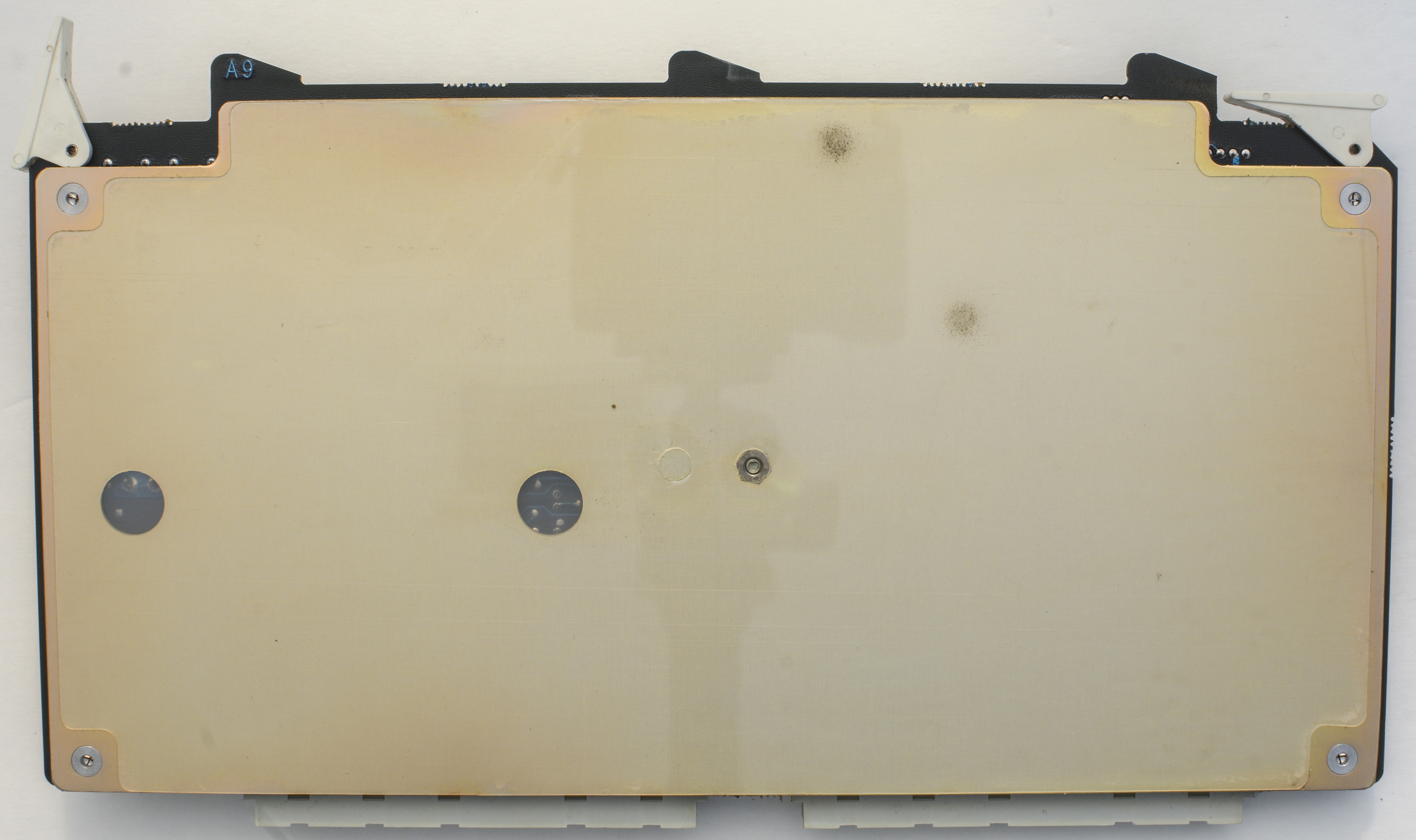
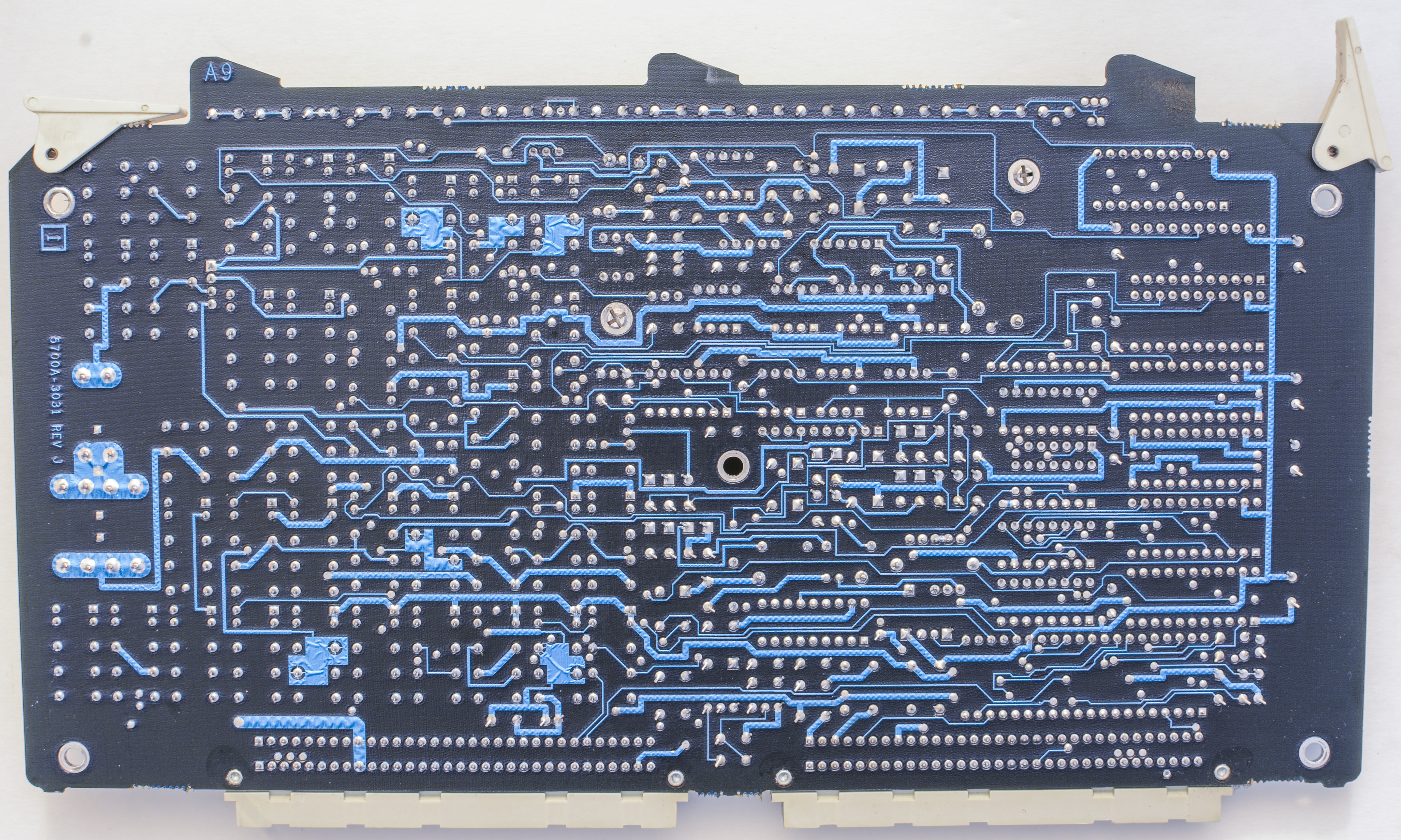
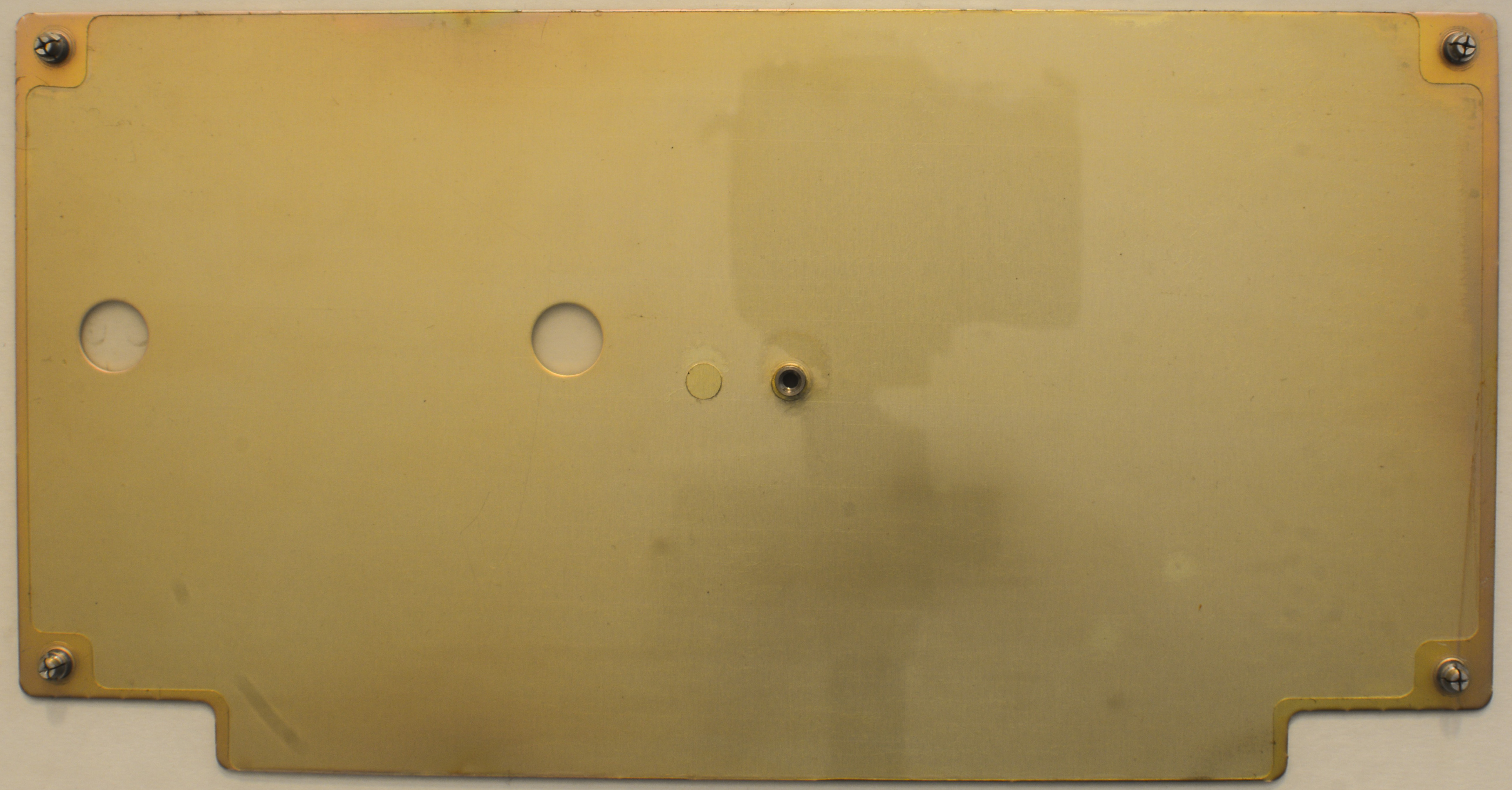
A9 OHMS,CAL PCA (Fluke P/N 775395)
Calibrator resistance references are located on this (for 1Ω 1.9Ω short resistance) and A10 PCBA (10Ω – 100MΩ). All resistors except highest 100 MΩ are routed with Kelvin 4-wire connections to cancel influence of routing/connection parasitic resistances. There is also reference 10KΩ/90KΩ 10:1 divider, lower part of which is used as internal calibration standard. During Artifact Calibration, this is the resistor which will get compared to external 10 KΩ standard.
Used Fluke proprietary resistors are designed and manufactured to have very low TCR, since the calibrator is specified at ±5°C around the calibration temperature, usually +22°C or +23°C. By design temperature coefficient is targeted near zero at +22°C. The temperature coefficient of the thin film networks increases slowly to 1 ppm/°C at about 8°C from the zero TC at 22°C.
The 90MΩ resistor that makes up most of the 100MΩ standard designed to have TC <10 ppm/°C. According to Fluke documents and test results, 1Ω and 1.9Ω resistors have a temperature coefficient of a few ppm per °C at reference temperature +22°C.


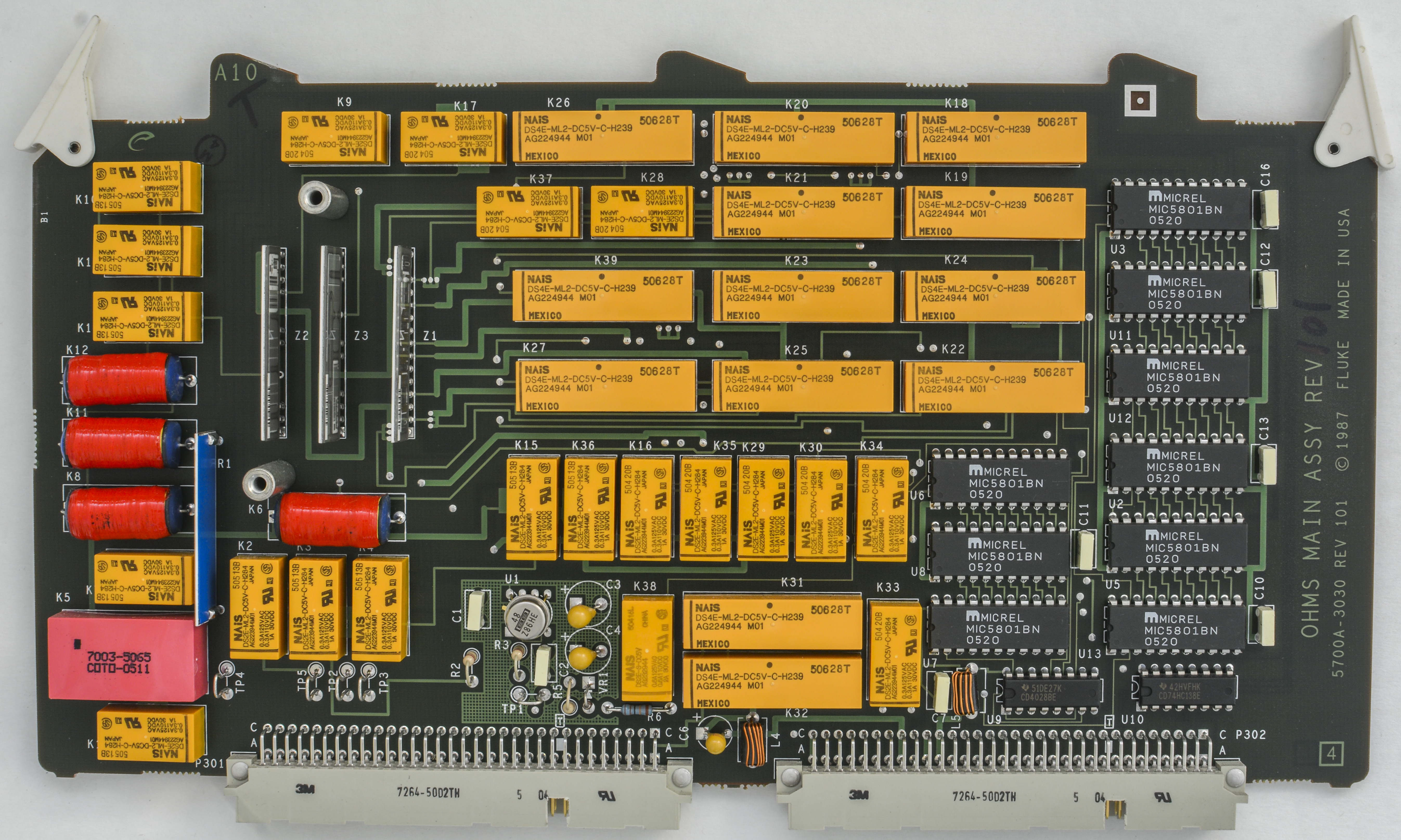
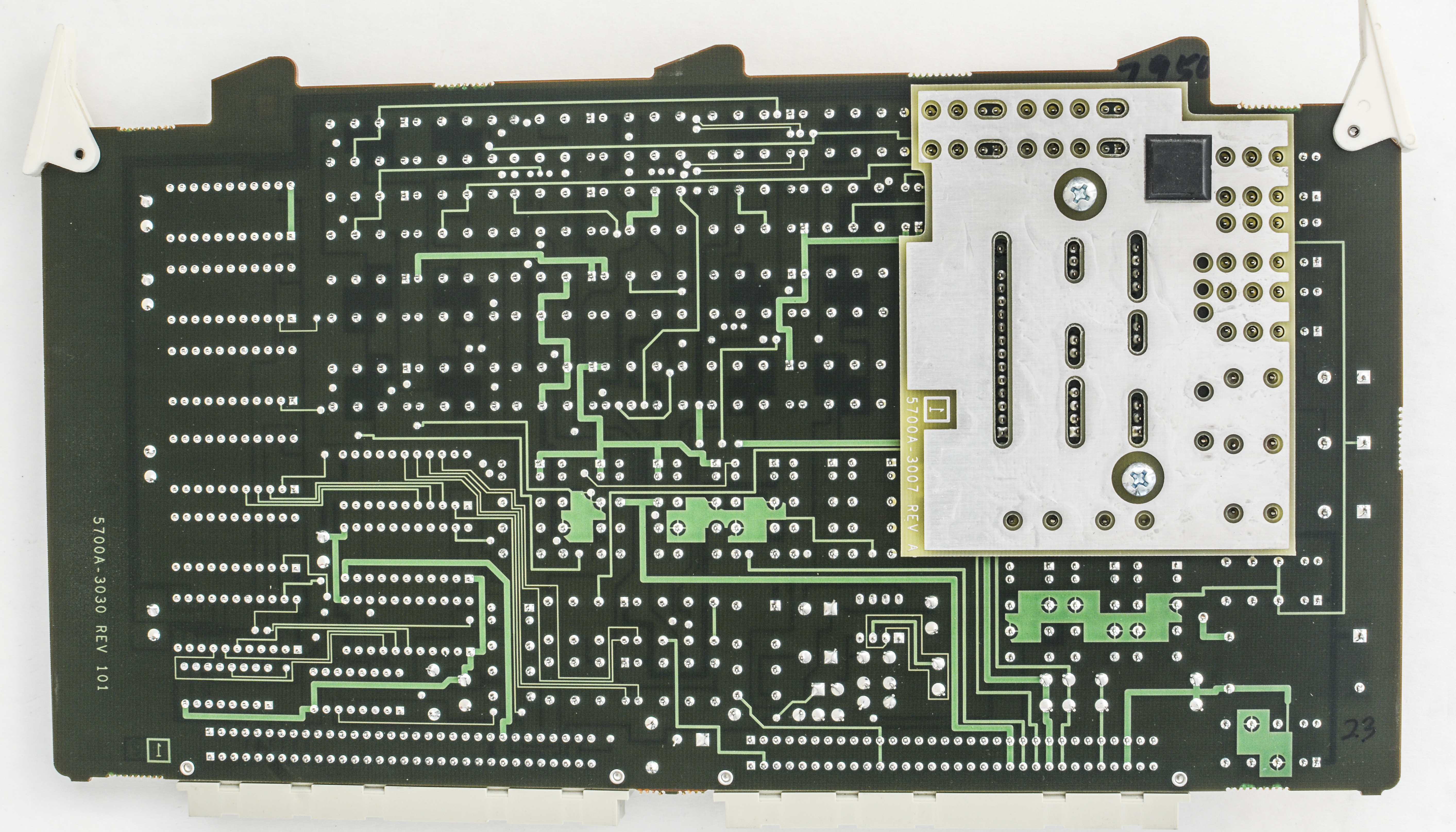
A10 OHMS,MAIN PCA (Fluke P/N 761114)
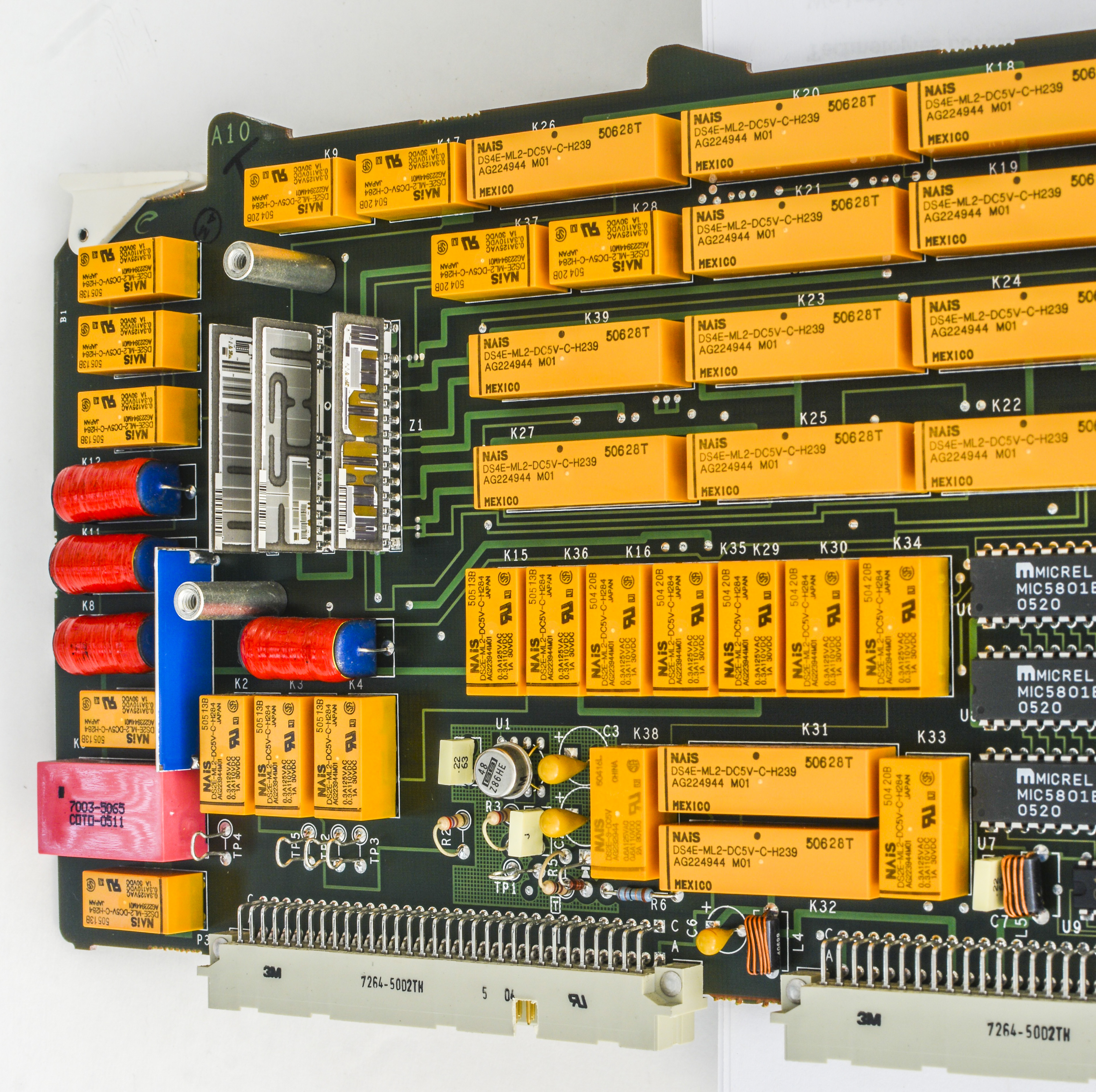
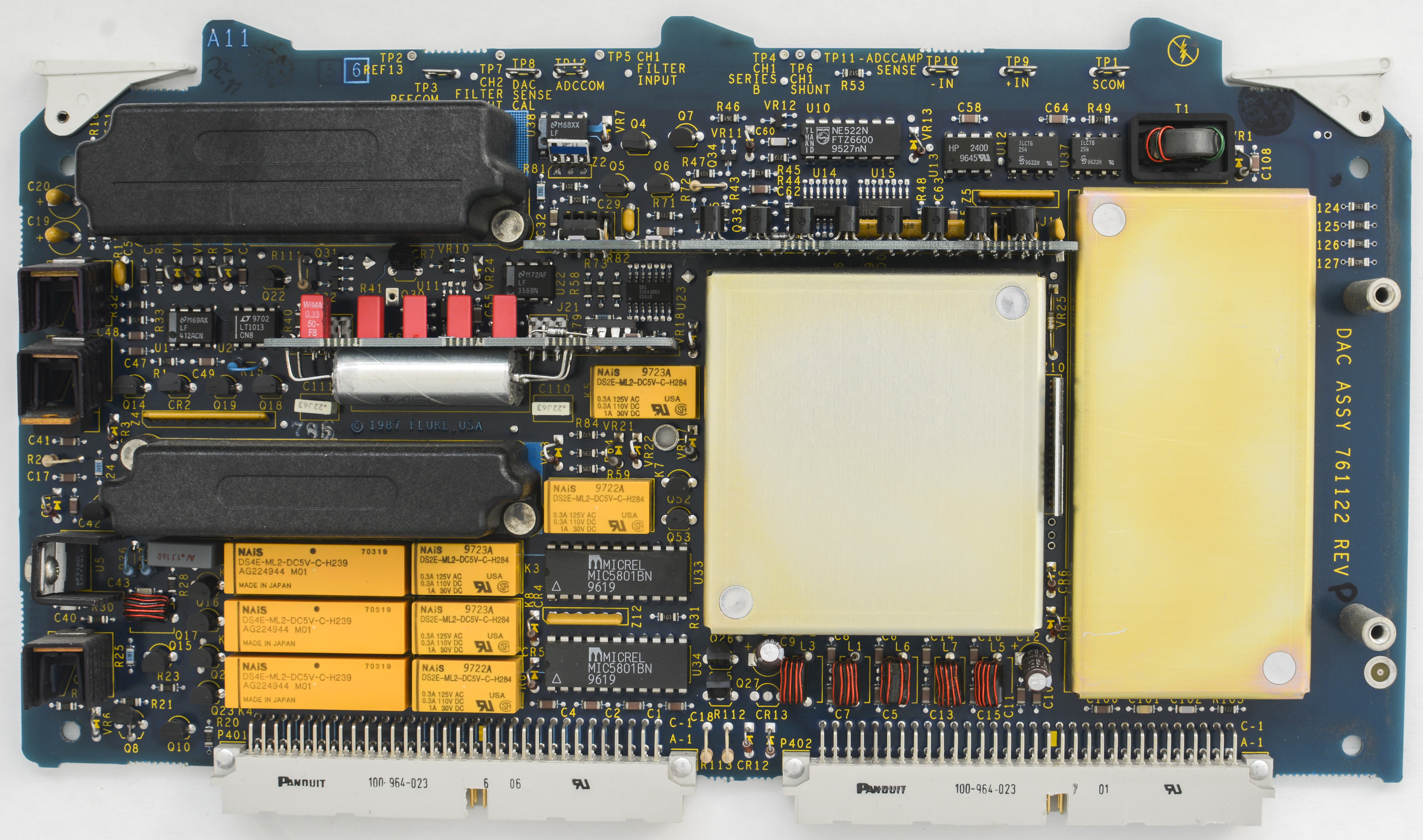
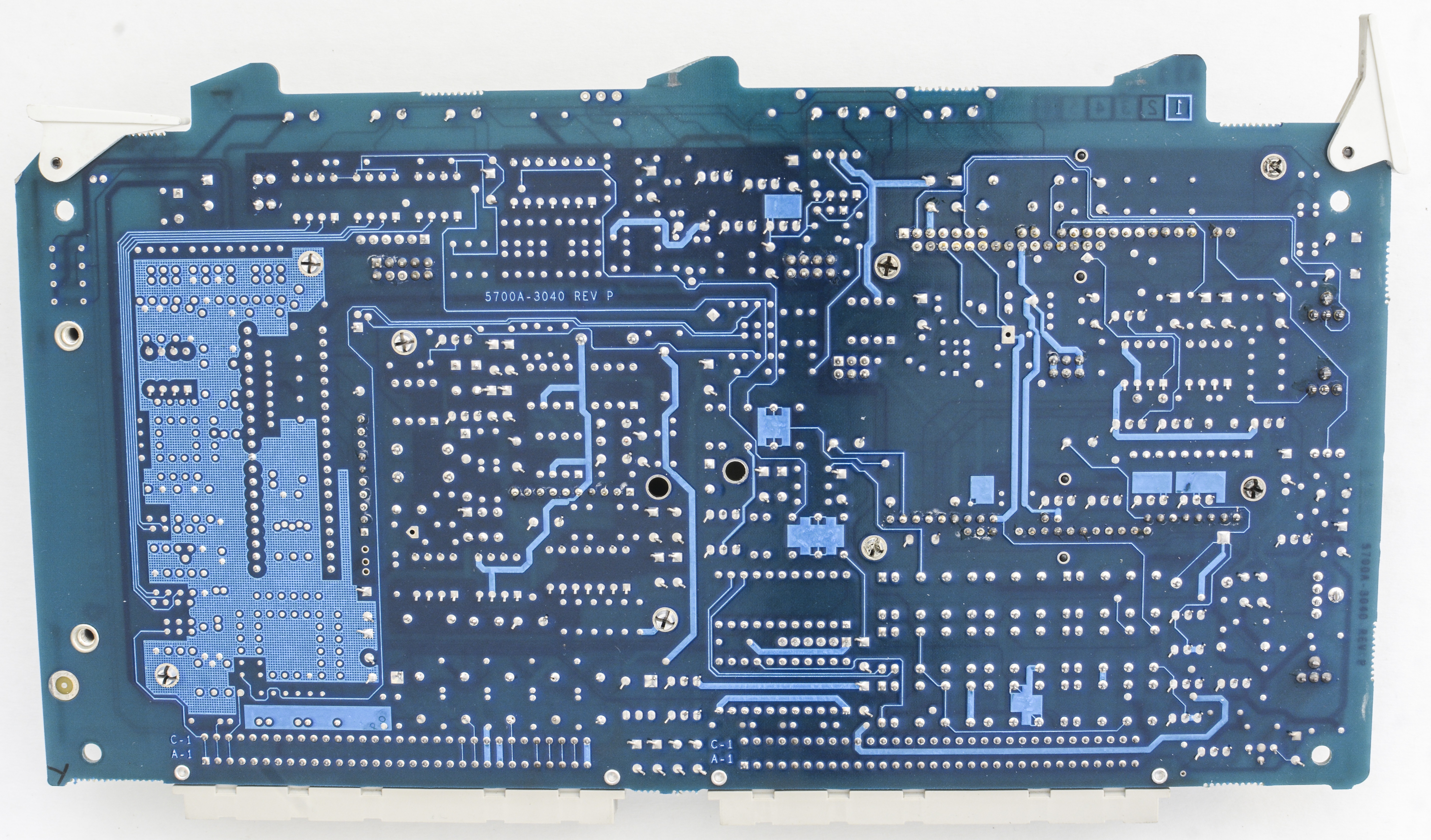
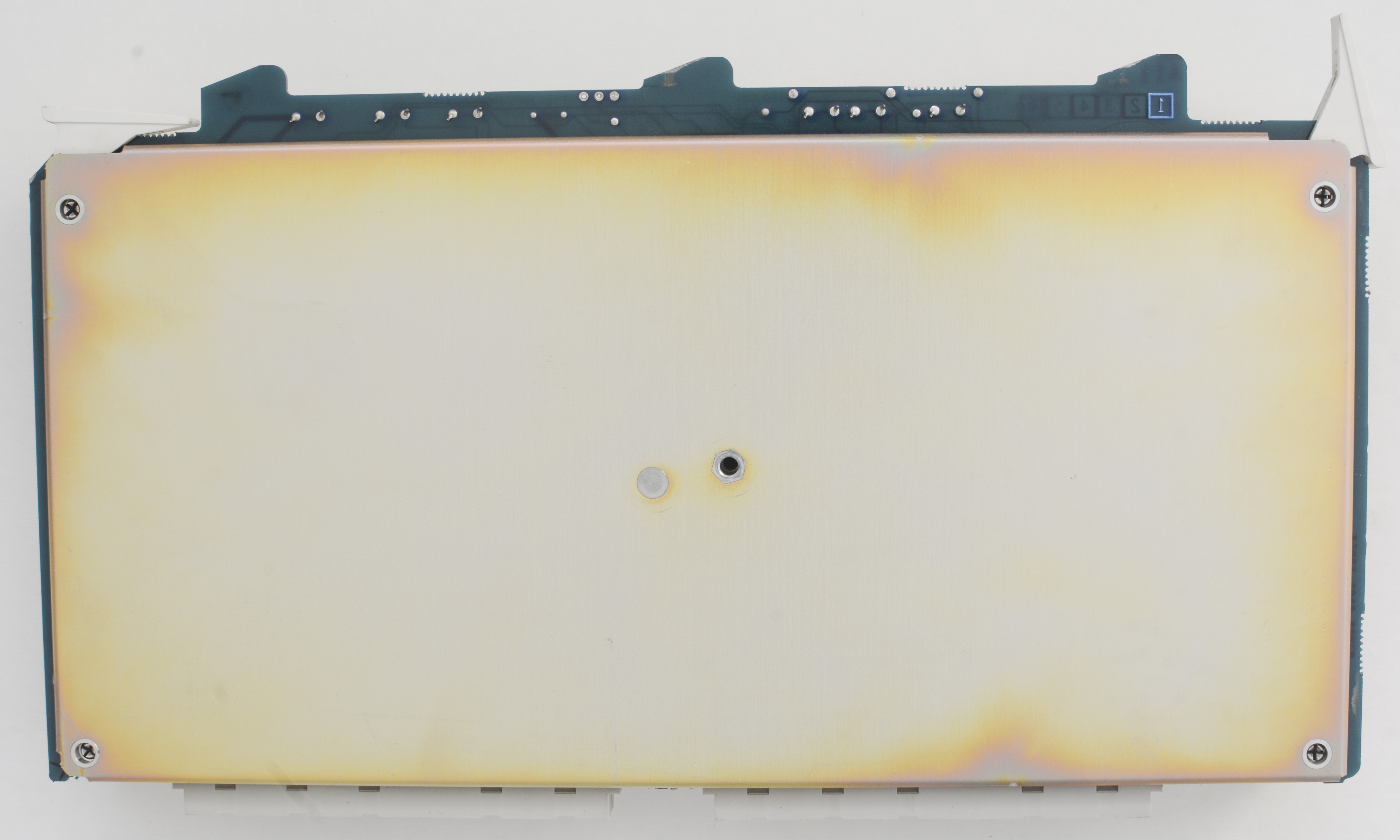
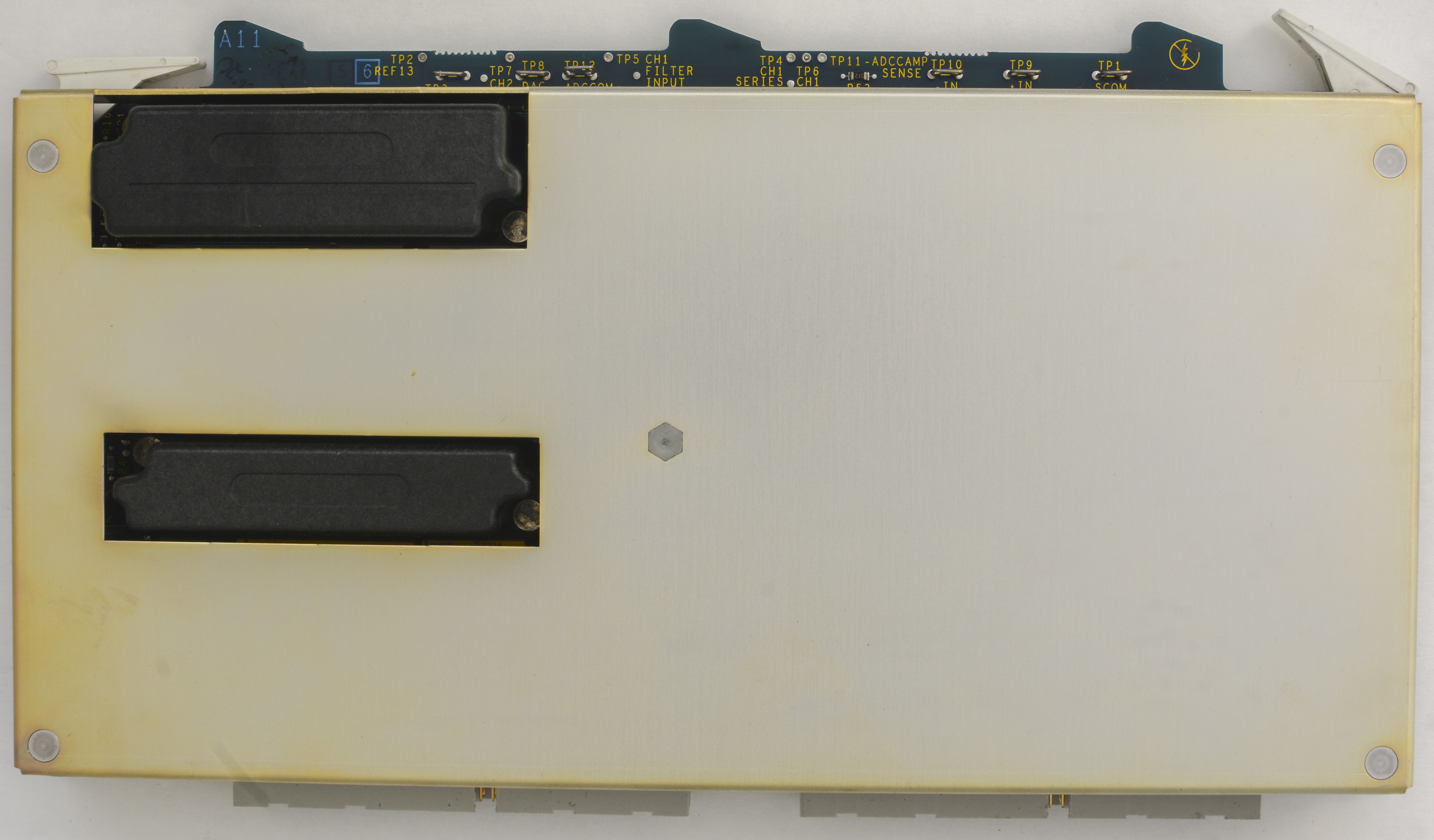
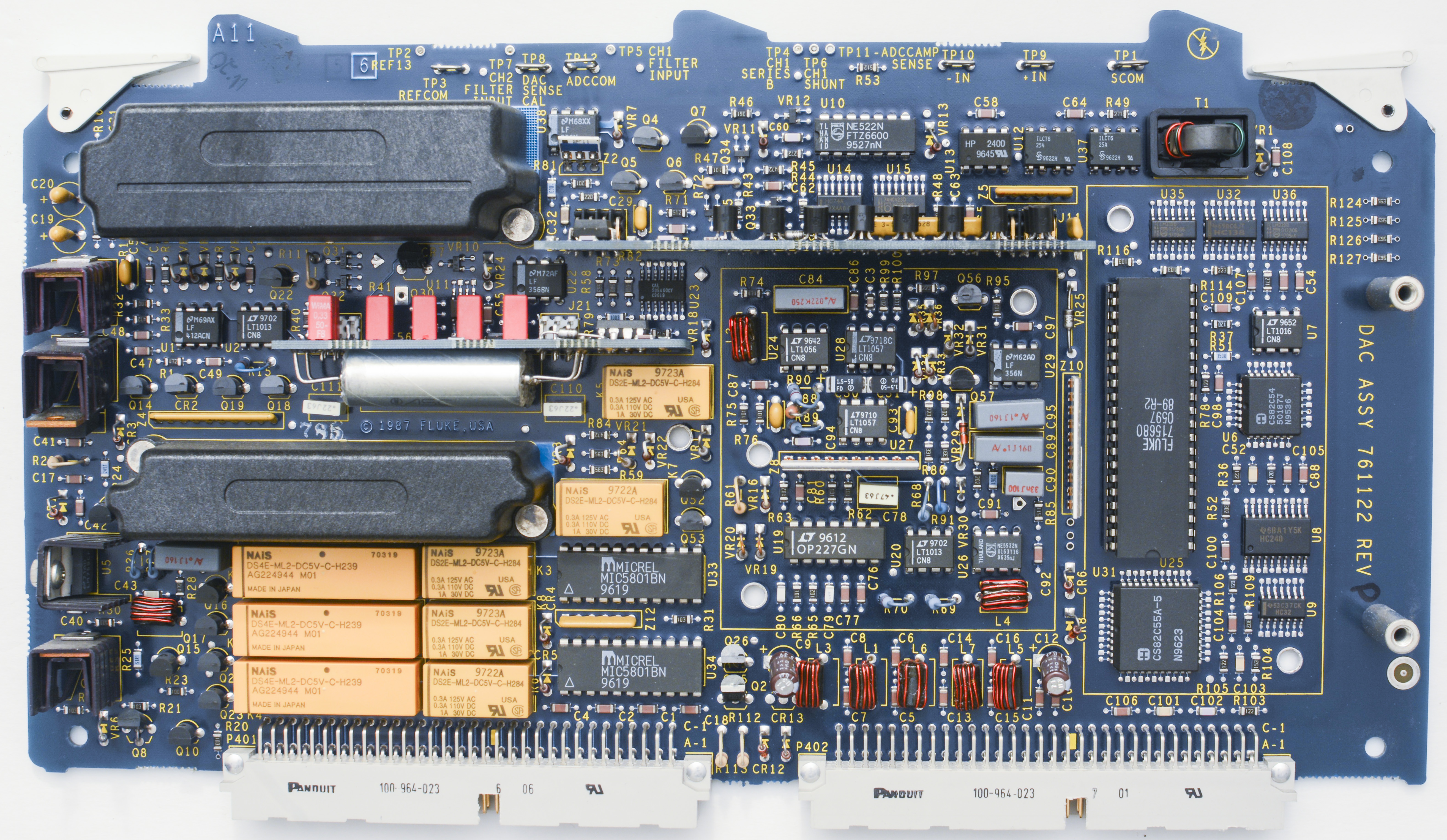
A11 DAC PCA (Fluke P/N 761122)
Heart of main DC voltage reference performance and stability are two SZA263/LTFLU-1 refamps, located on heated substrate with TaN resistor networks in shielded can on this board. Similar reference arrangement idea was used in old Fluke 5442B, but with famous teal-colored wire-wound resistors on regular FR4 PCB.


A12 Oscillator control PCA (Fluke P/N 761130)

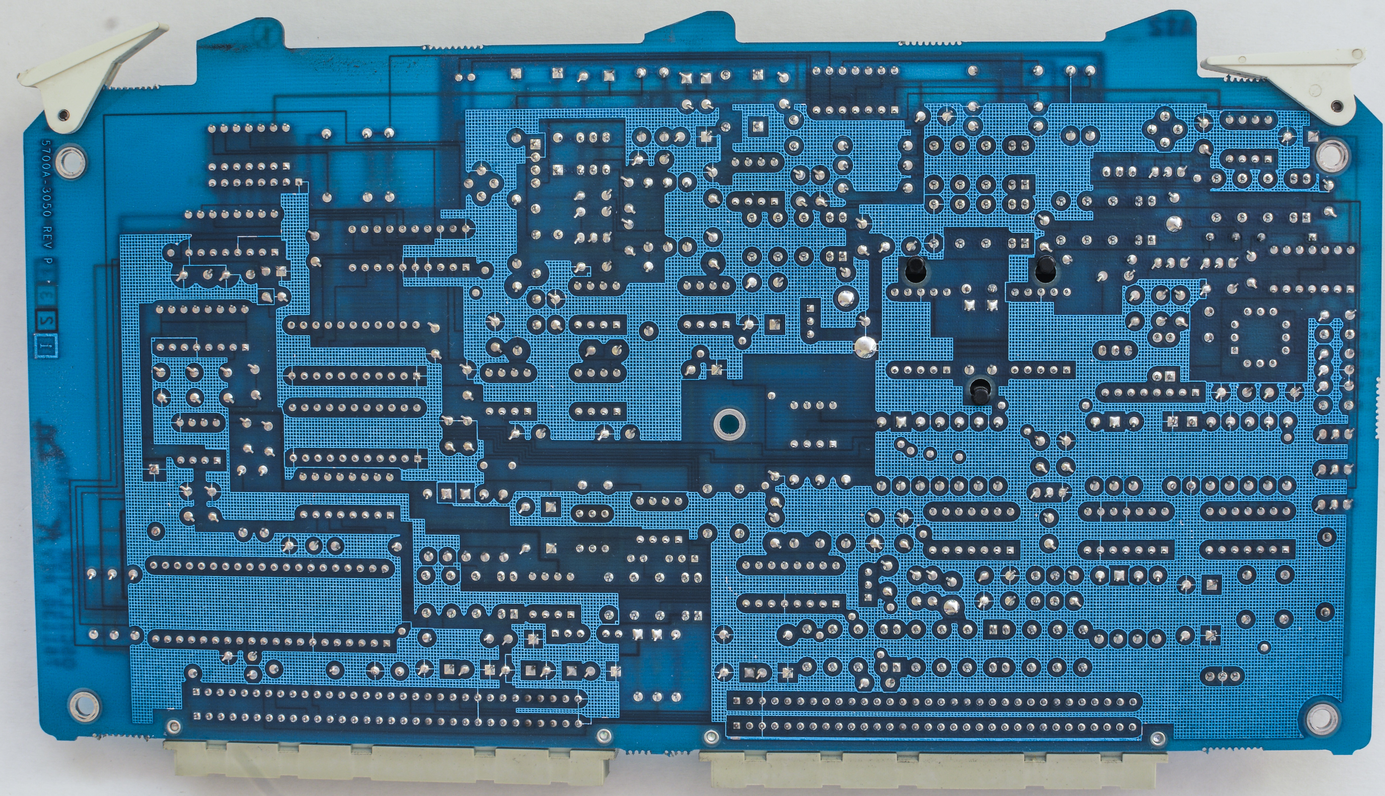
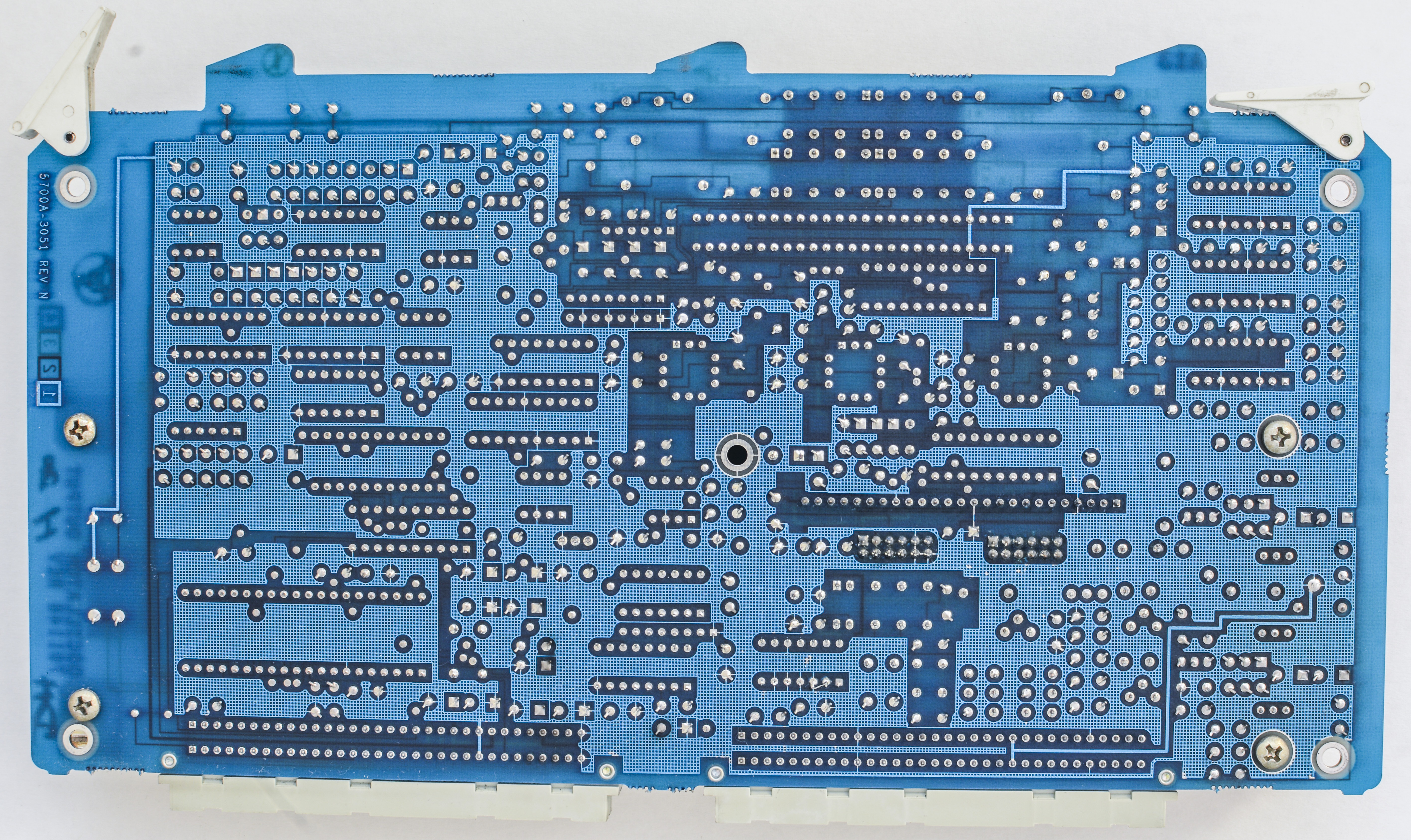
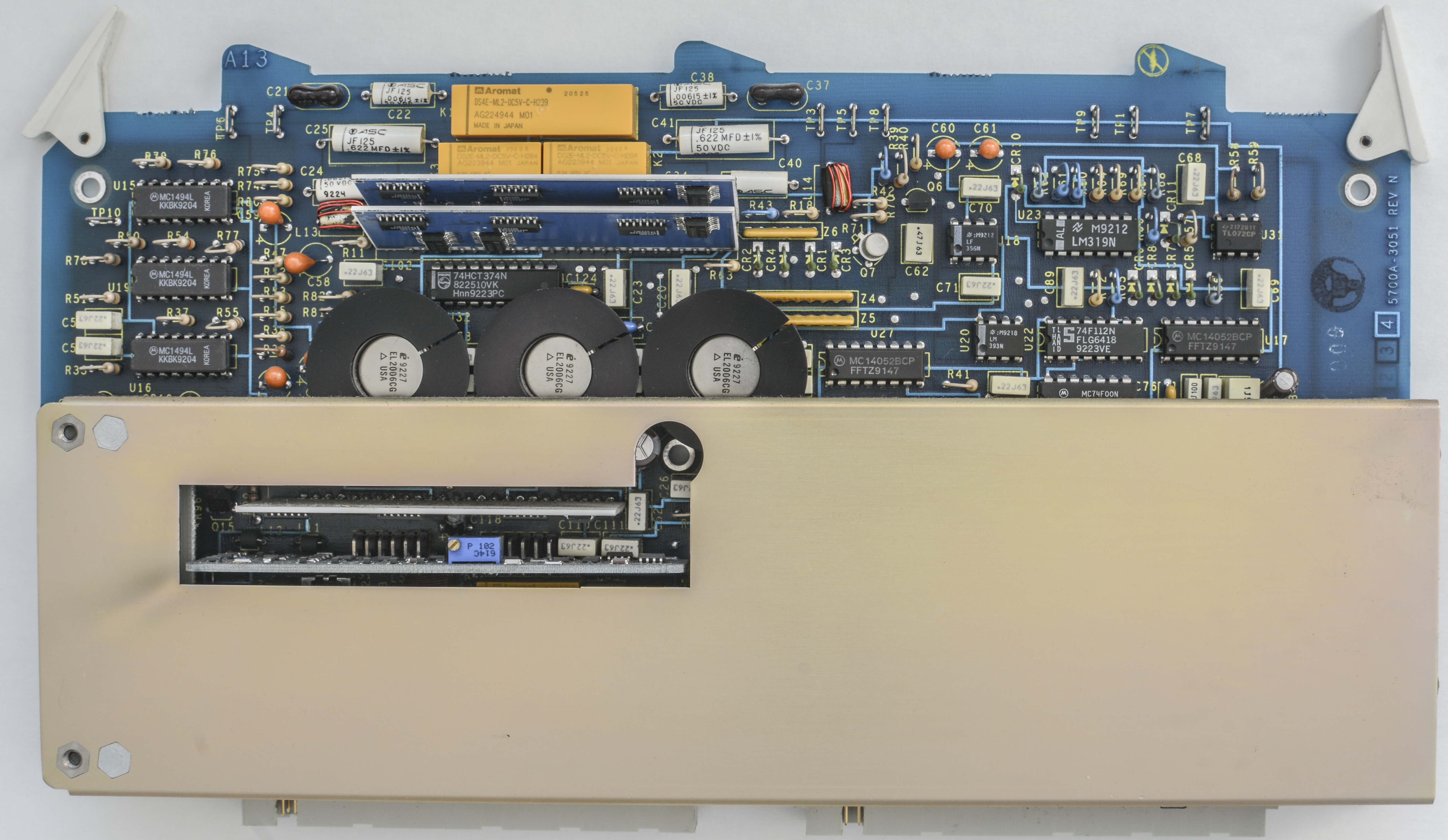
A13 Oscillator output, PCA (Fluke P/N 761148)

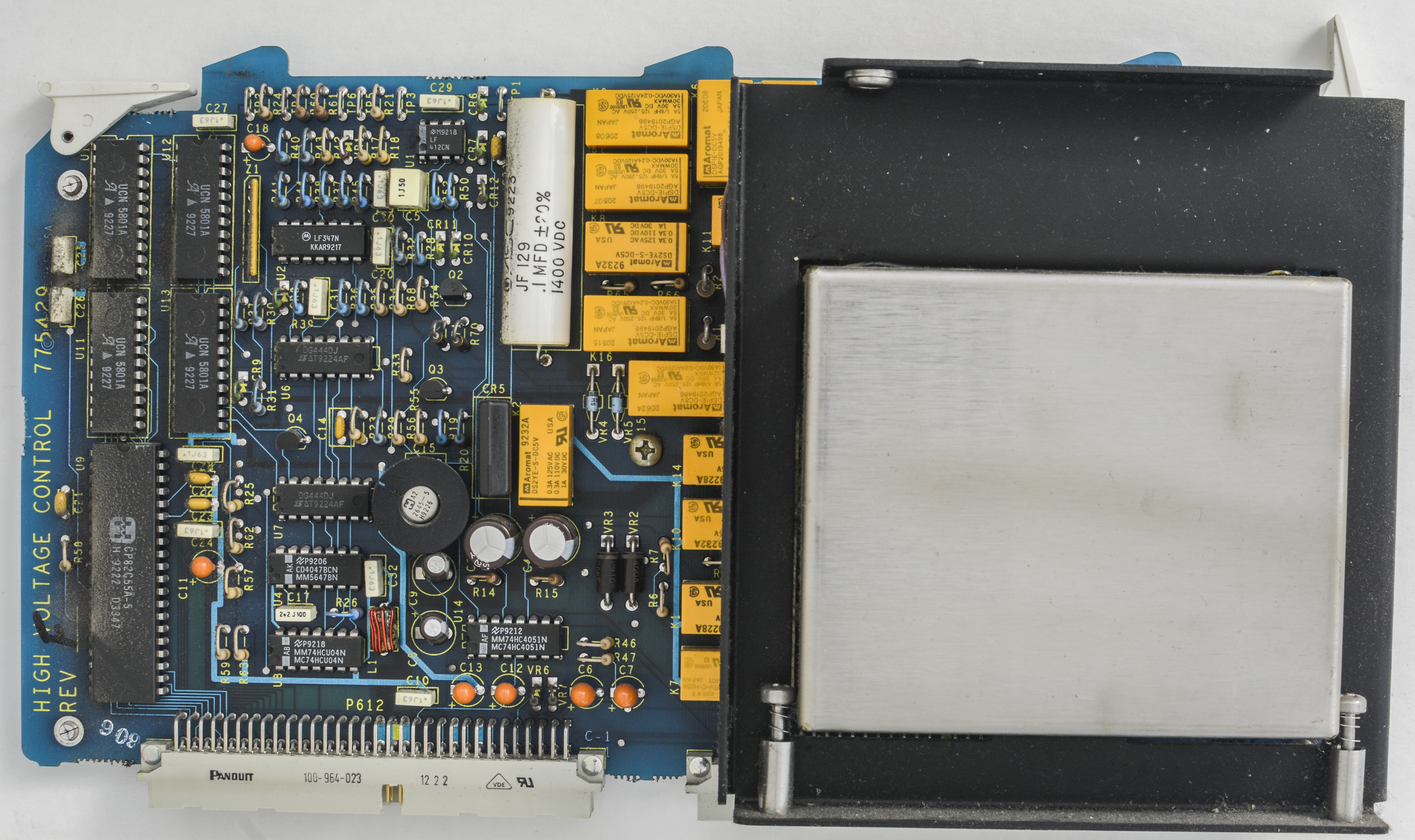
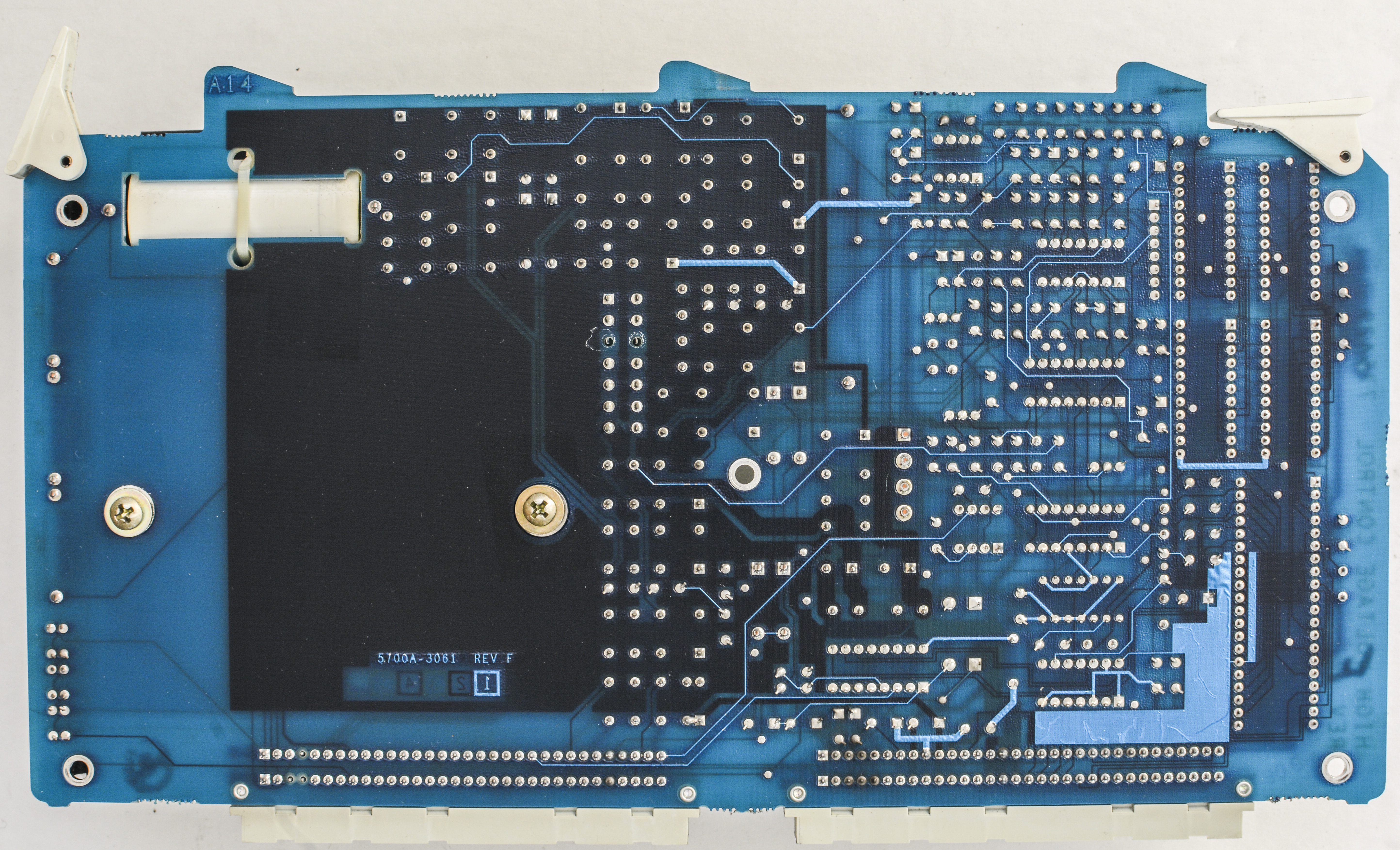
A14 High voltage control PCA (Fluke P/N 775429)


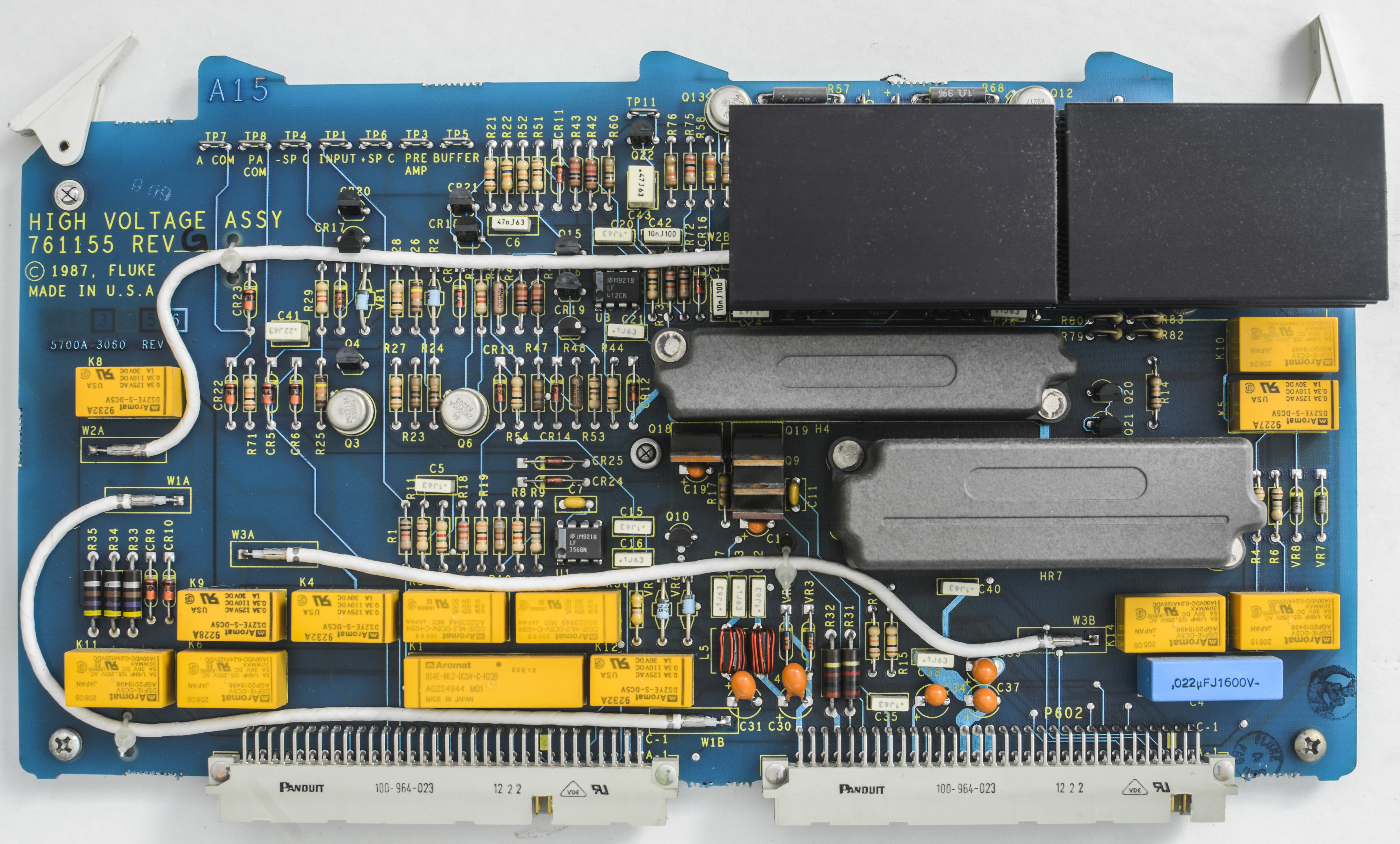
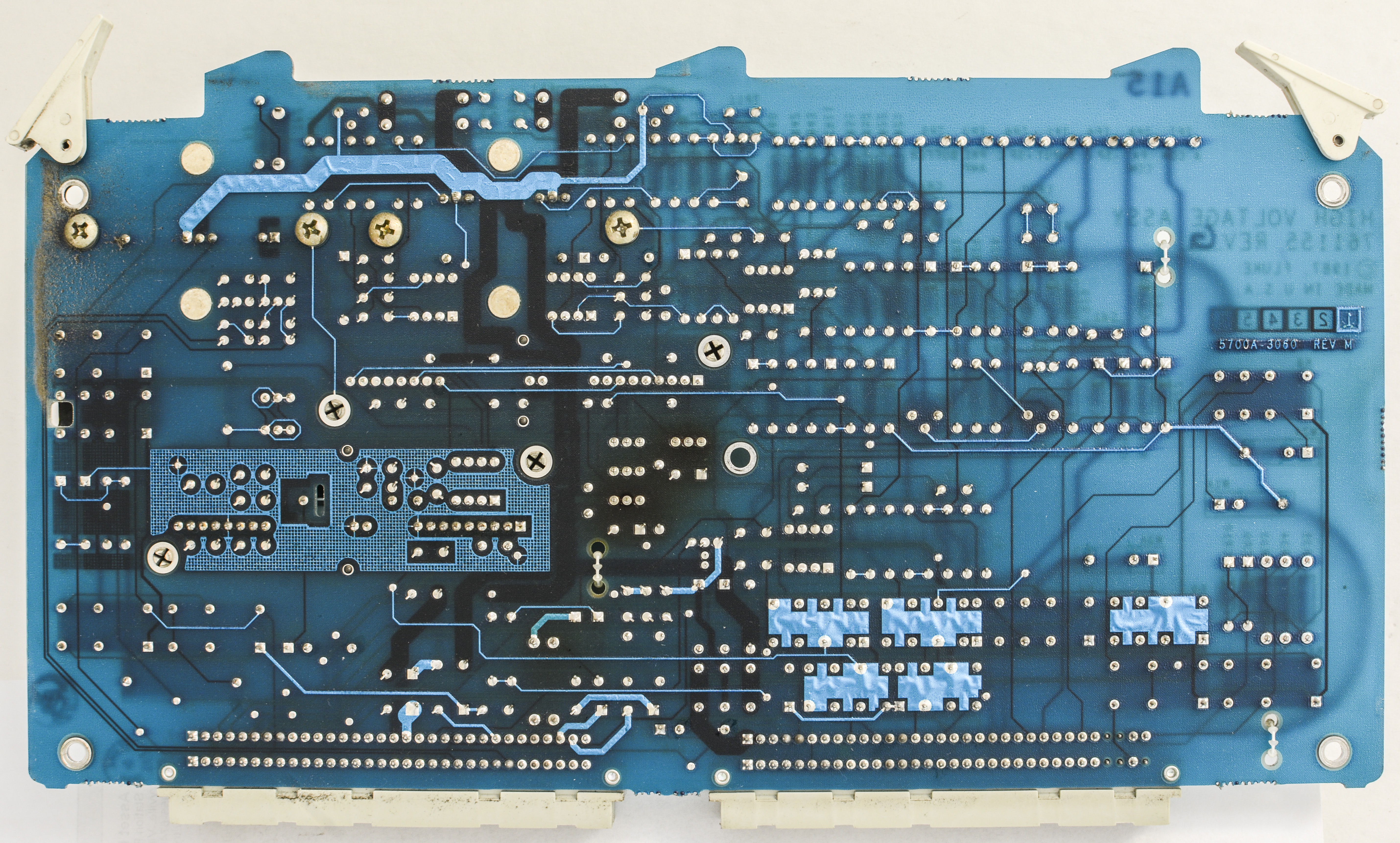
A15 High voltage/High current PCA (Fluke P/N 761155)


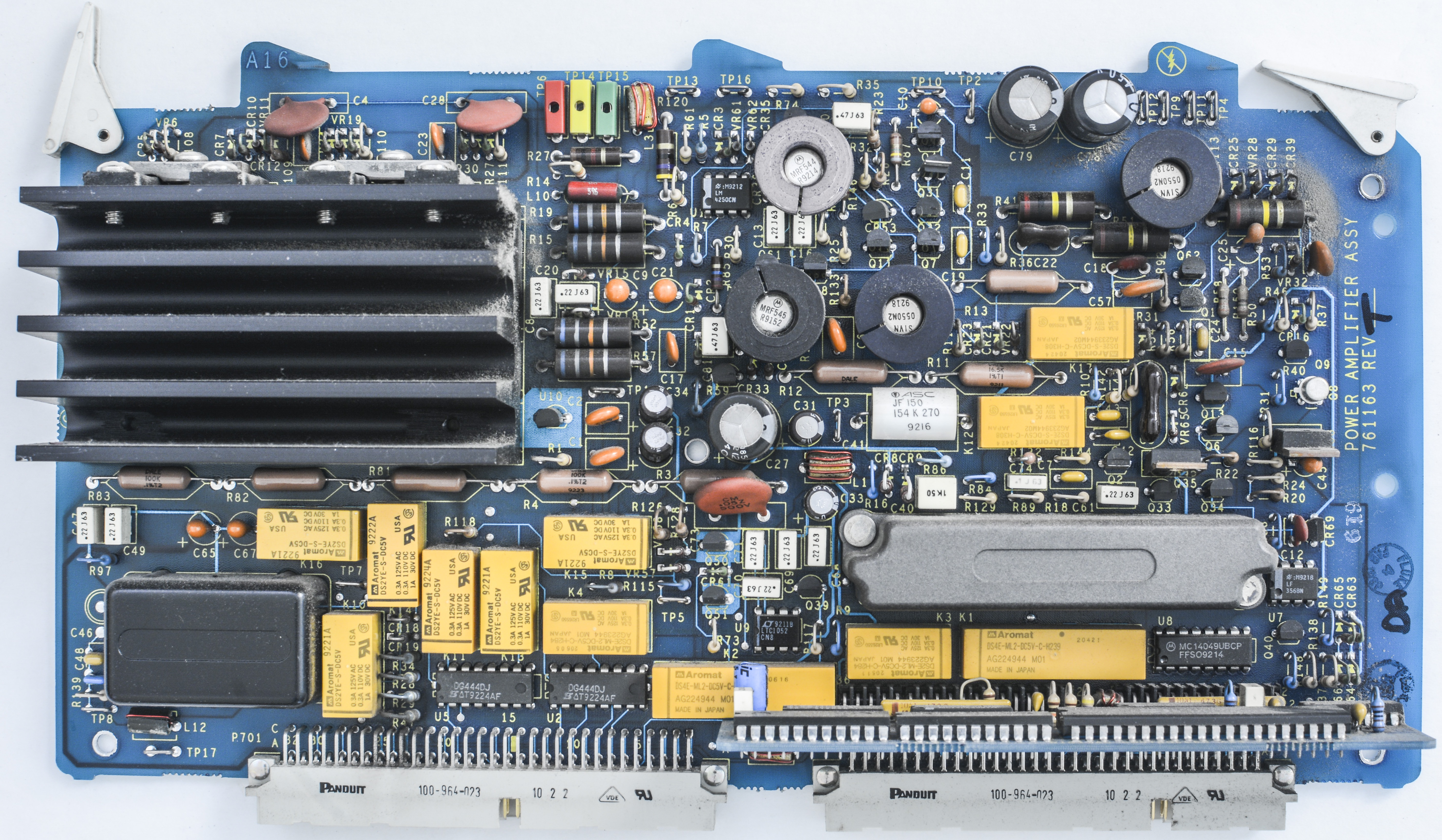
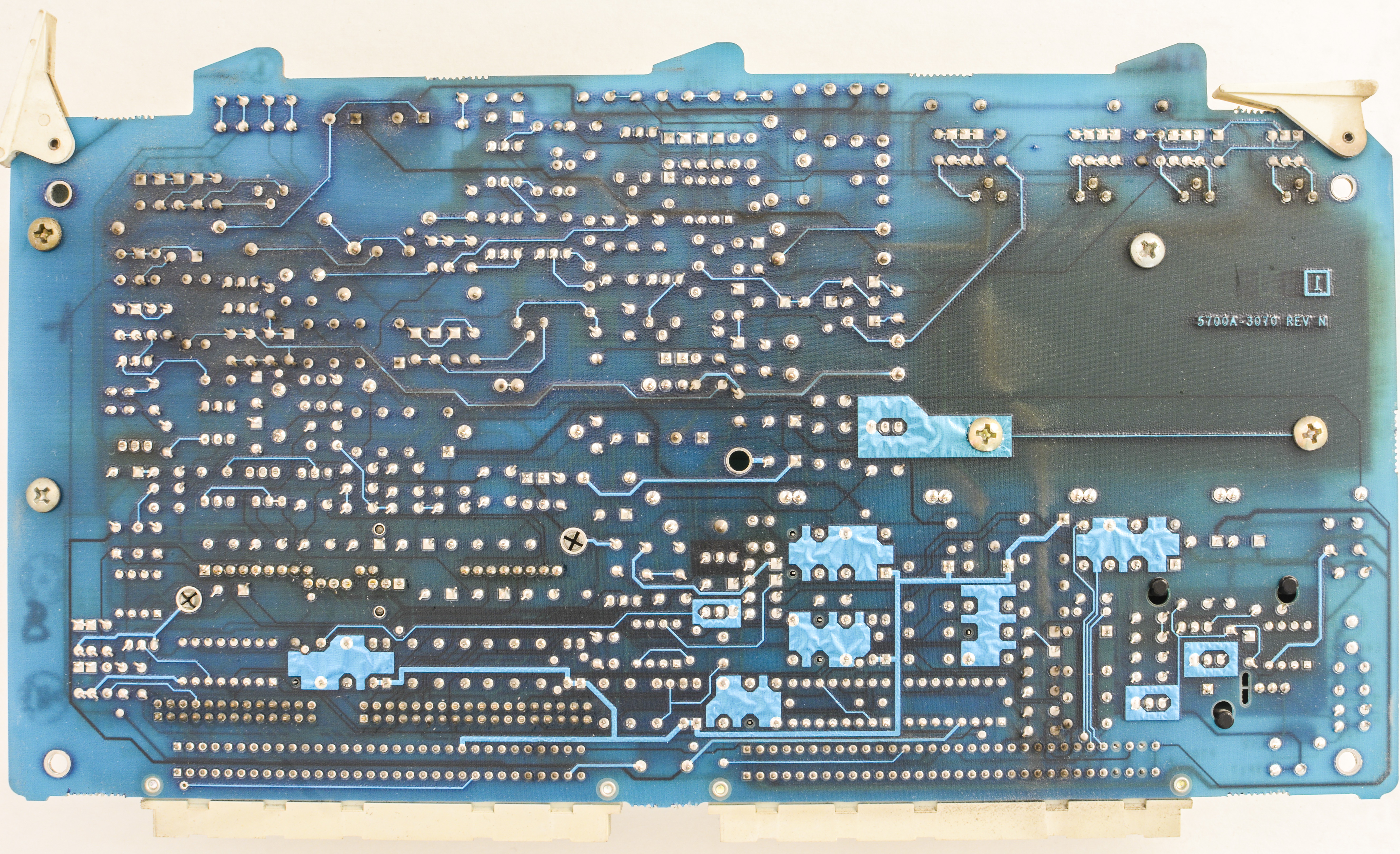
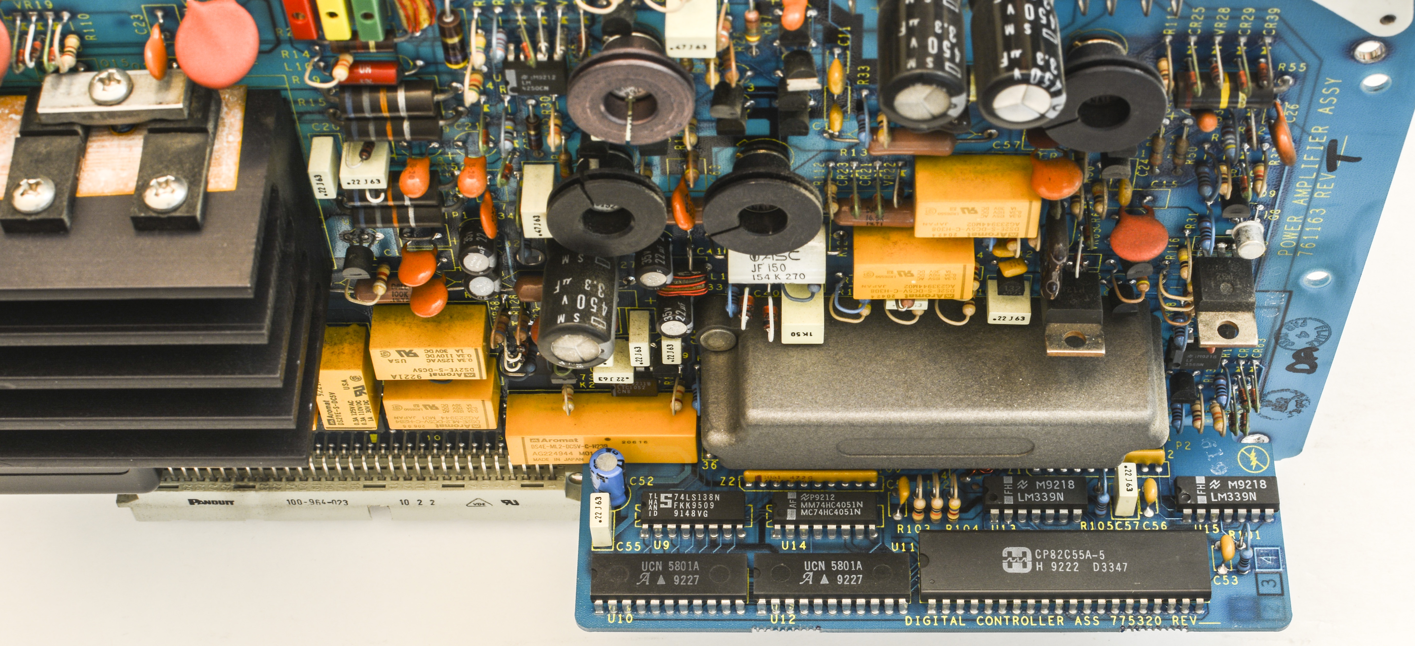
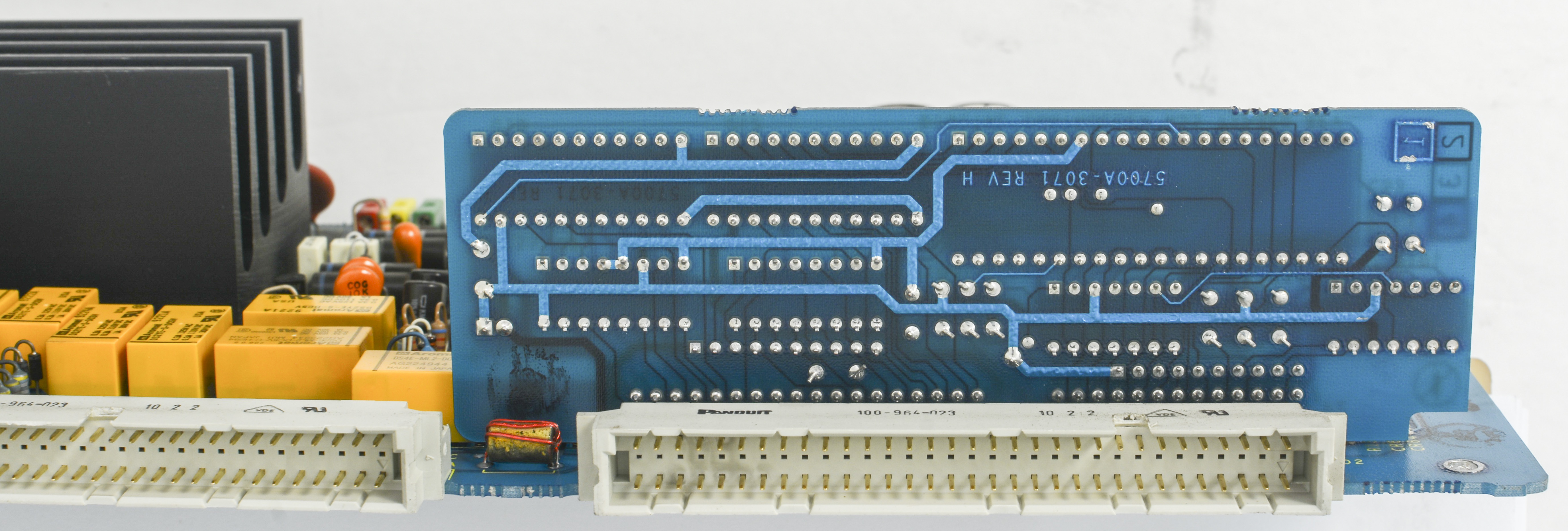
A16 Power Amplifier PCA (Fluke P/N 761163)


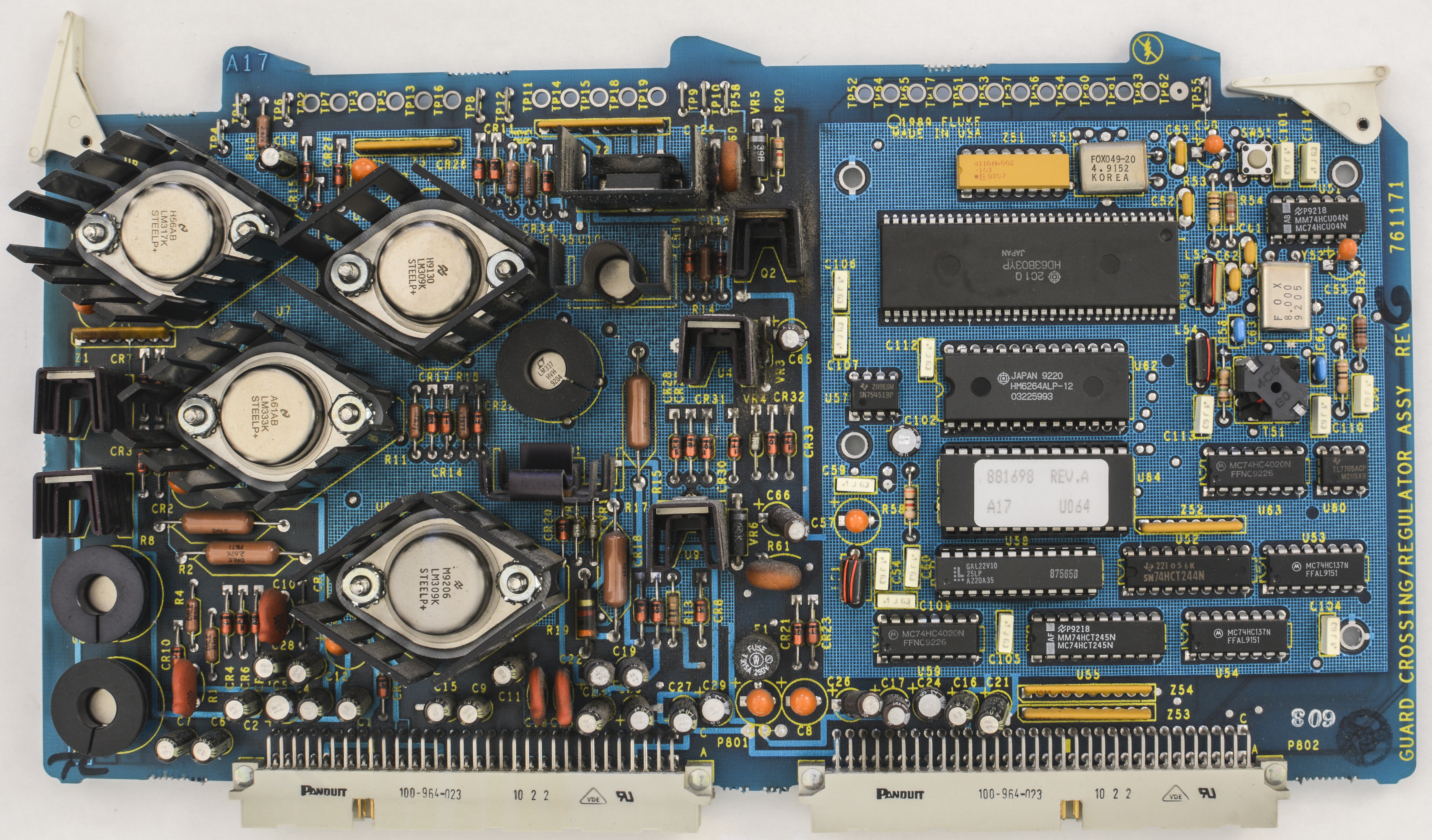
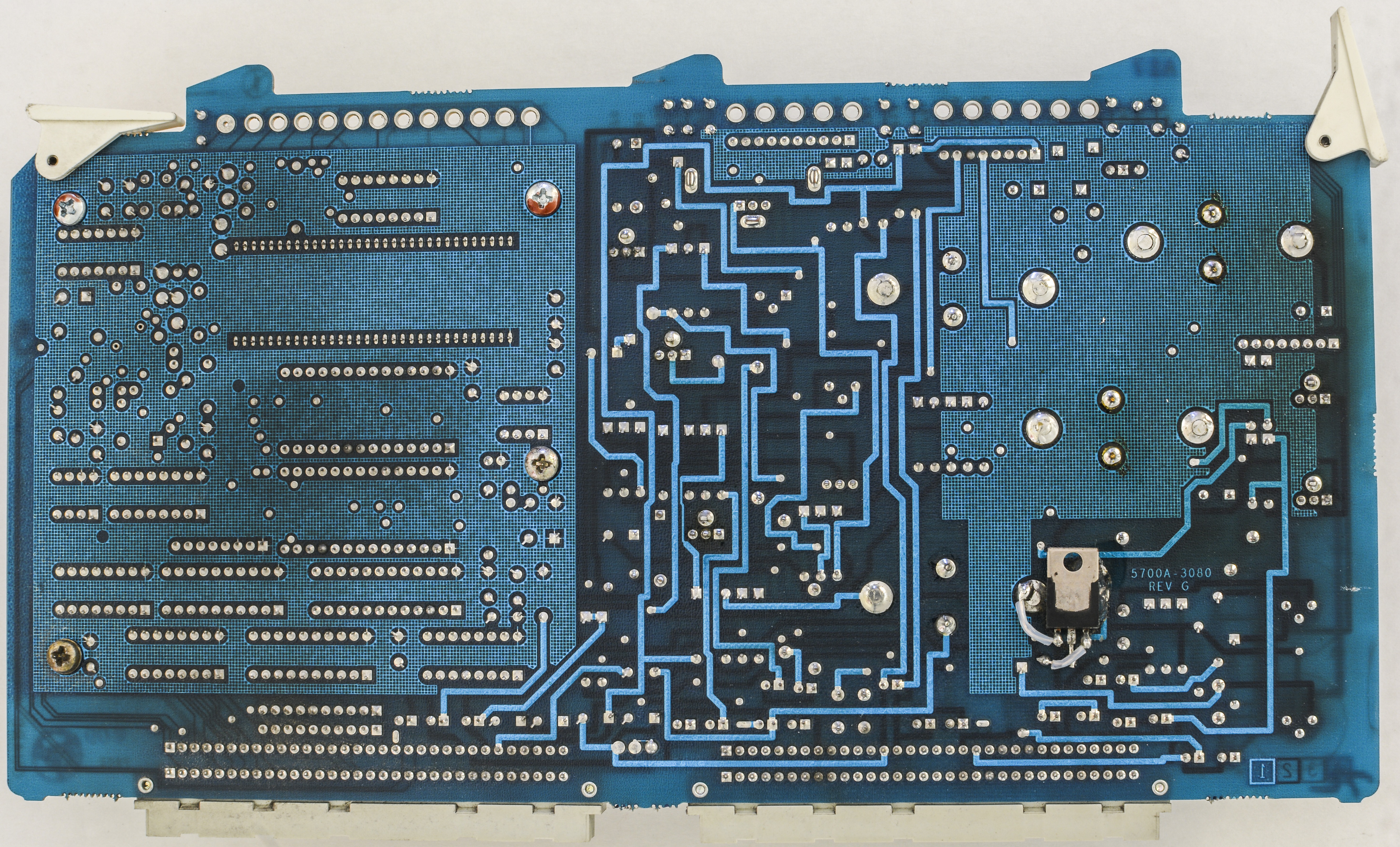
A17 Regulator/Guard crossing PCA (Fluke P/N 761171)
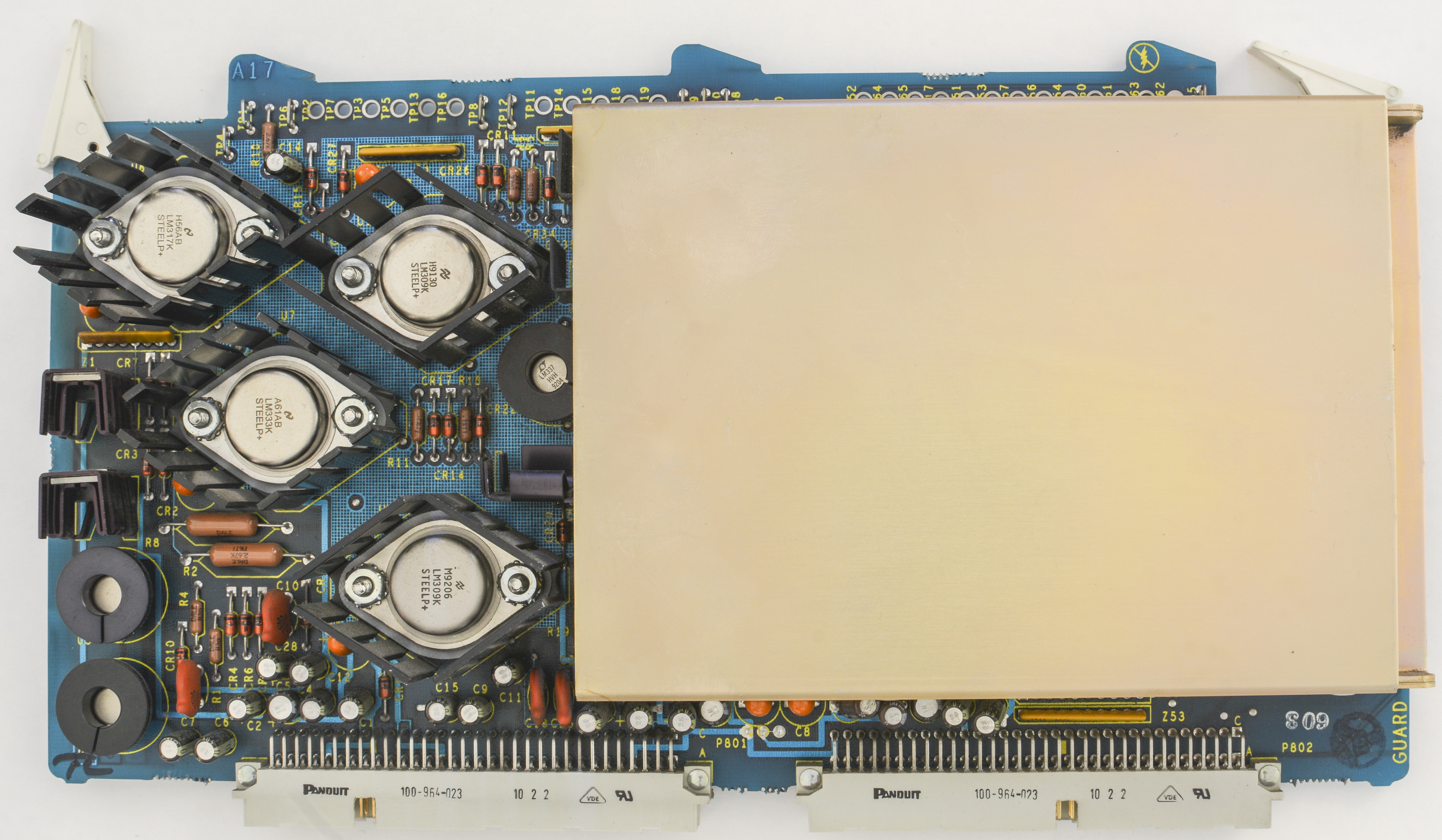
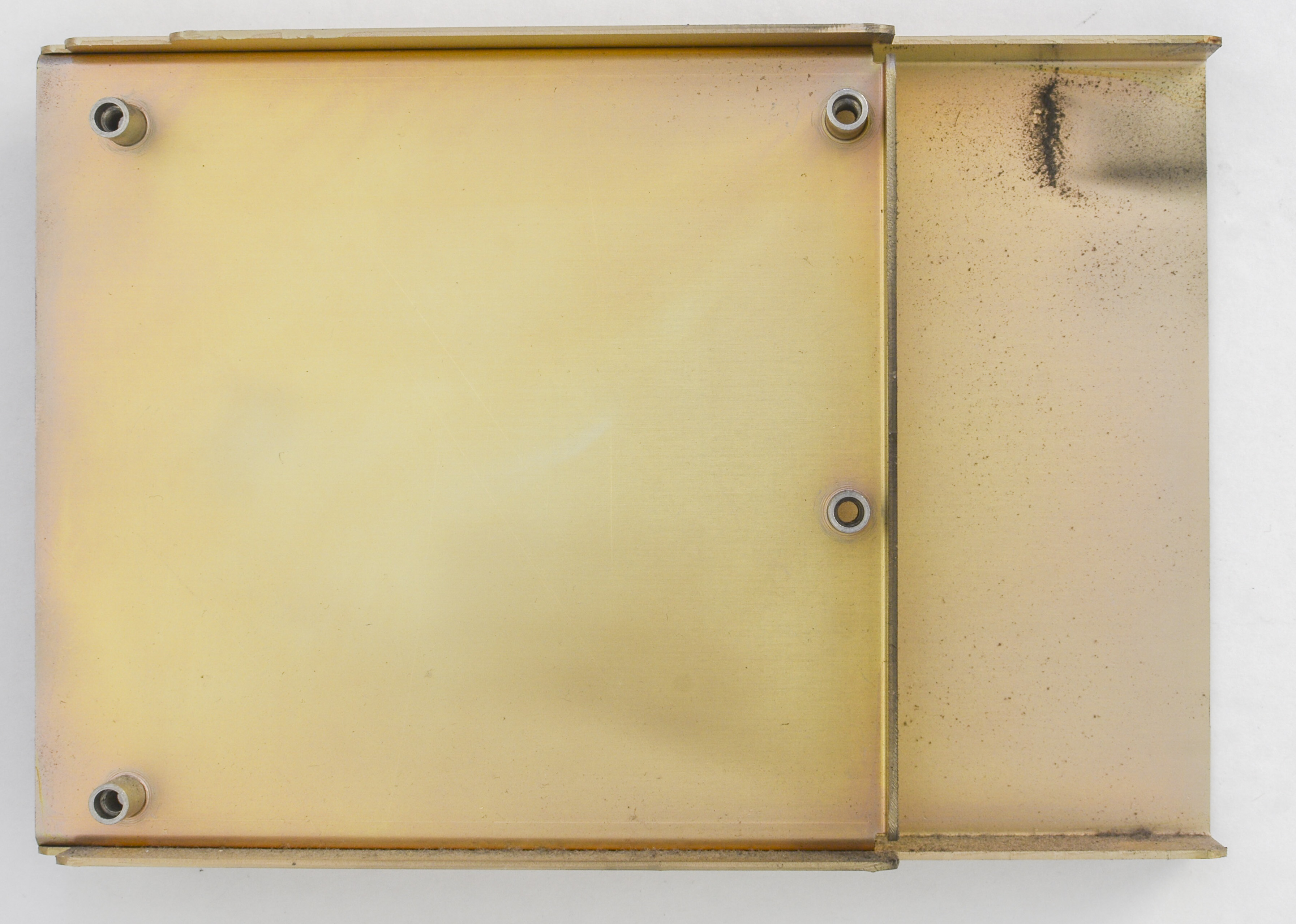
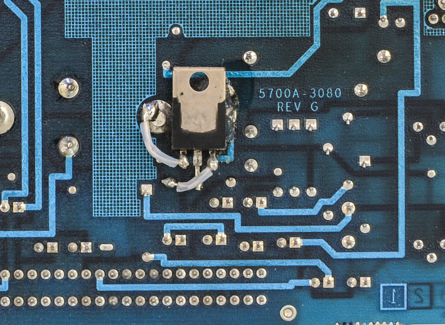
And no design is perfect, even 30K$ calibrator from Fluke. Lonely TO-220 regulator or transistor just hanging in there on jump wires on bottom side of the board.
A18 Filter/PA PCA (Fluke P/N 761189)

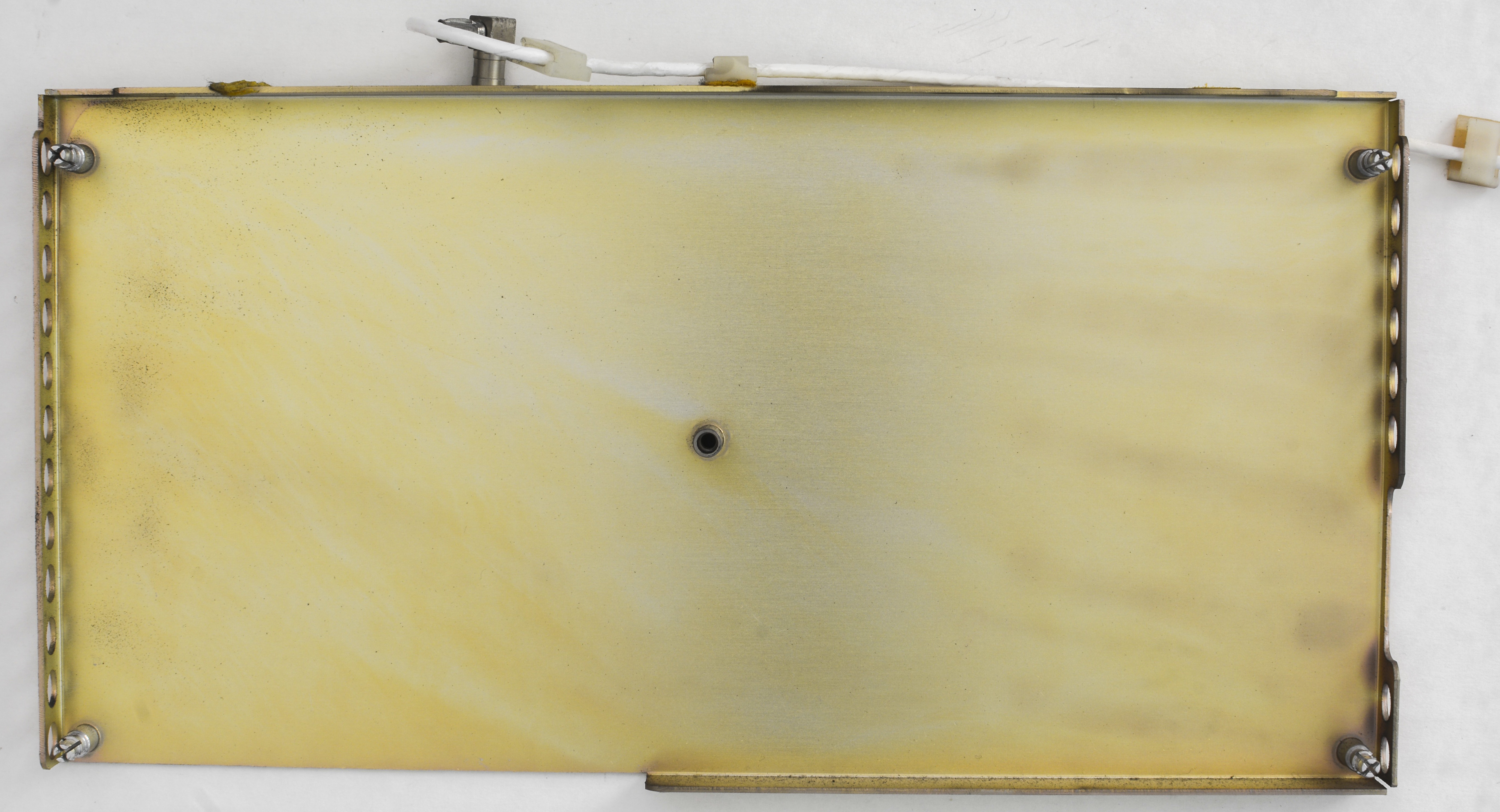
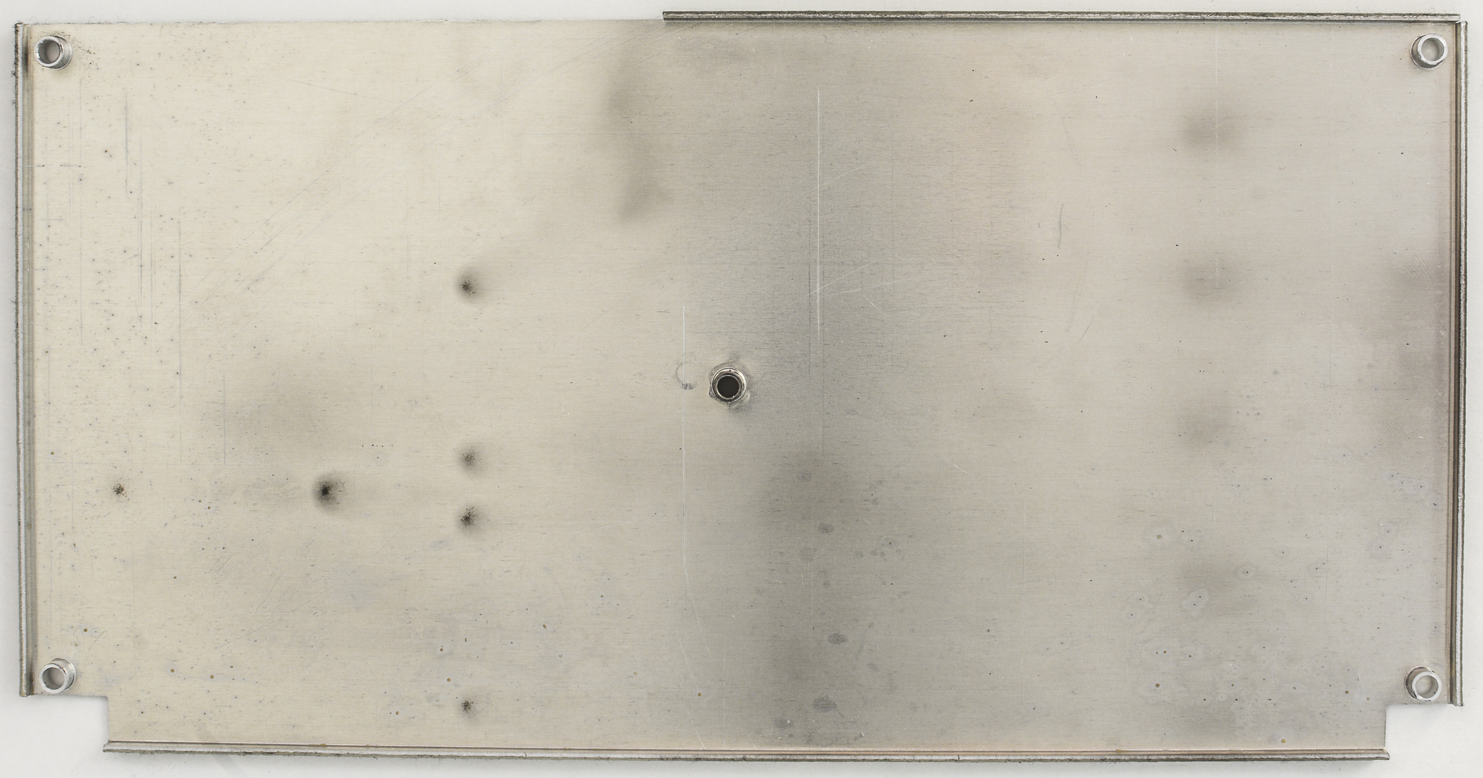
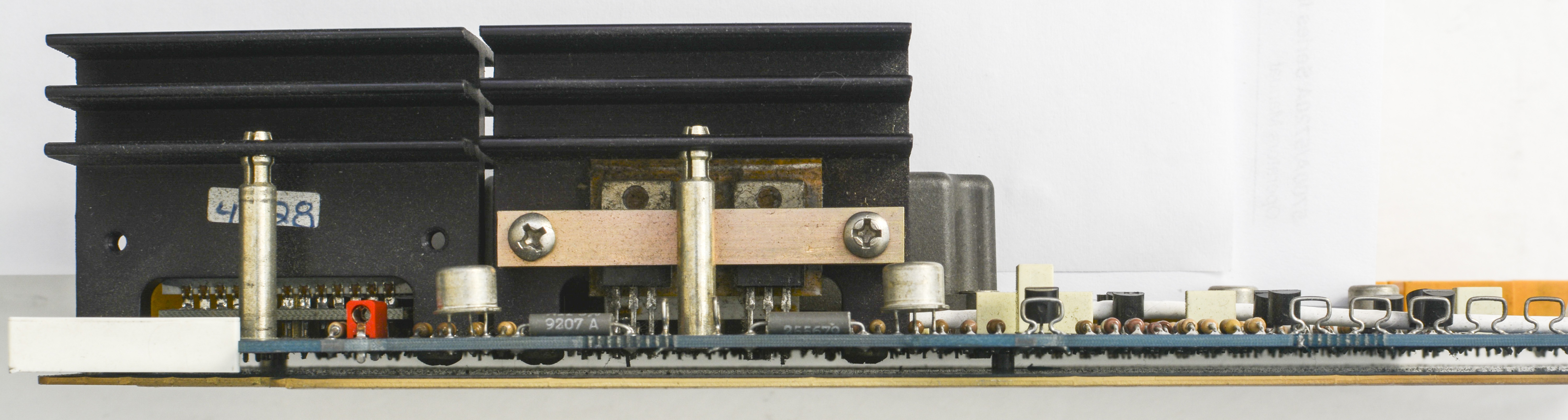
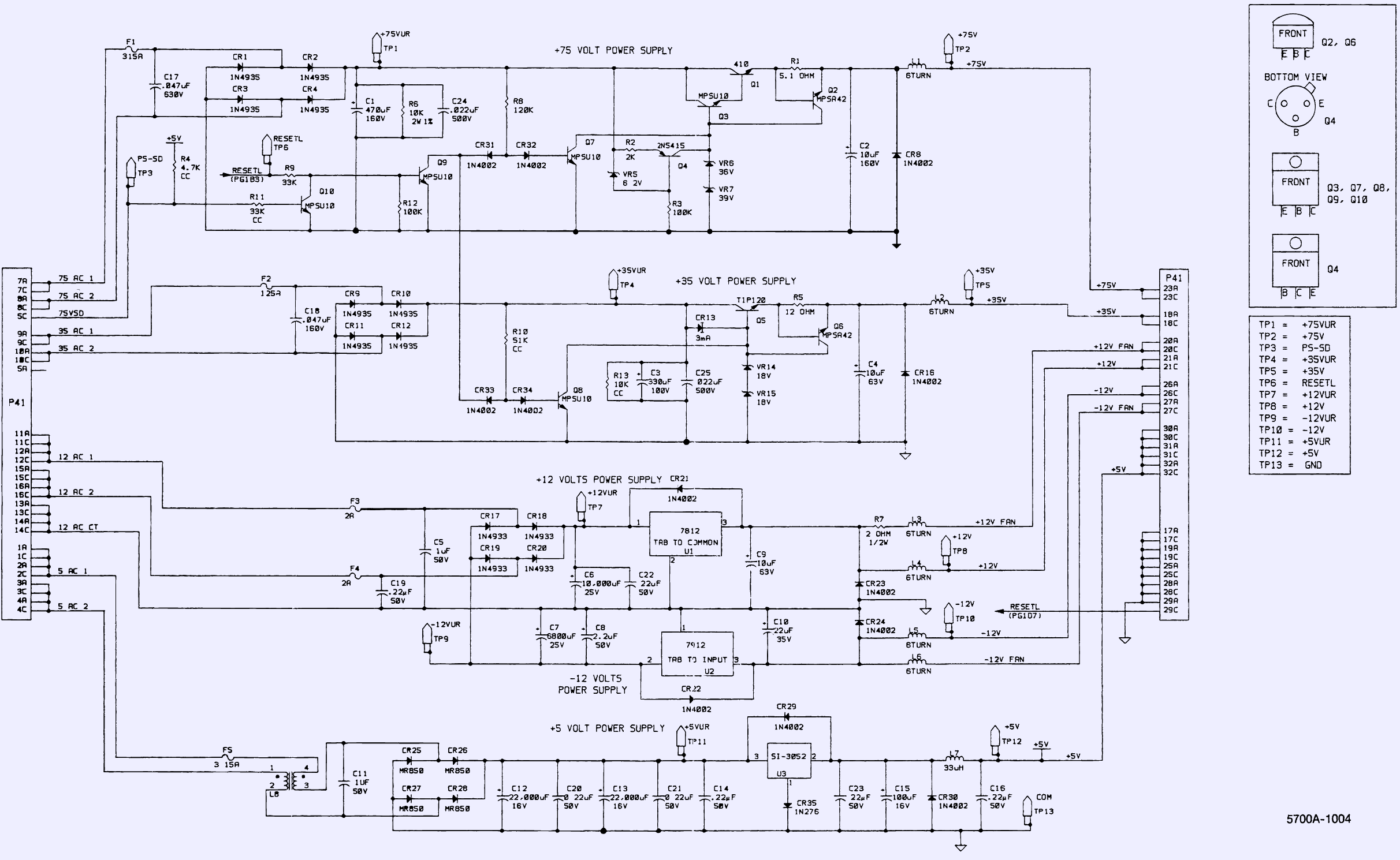
A19 Digital power supply PCA

This 5700A-1604 board, A19 with part number 761056 have Revision F and taking AC outputs from A22 mains transformer secondary windings and generate various DC voltages.
There are nice accessible test points on top edge, which we will probe during service. According to date code on parts, such as Q1 RCA410 pass transistor, this board is manufactured in 1992. This makes it 24 year old, which means all electrolytic capacitors are up for replacement.
| Test point name | Rated voltage | Measured voltage | Condition |
|---|---|---|---|
| TP1 | +75V unregulated | ||
| TP2 | +75V regulated | ||
| TP3 | PS_SD logic | Shutdown PSU signal | |
| TP4 | +35V unregulated | ||
| TP5 | +35V regulated | ||
| TP6 | RESETL logic | Reset input signal | |
| TP7 | +12V unregulated | ||
| TP8 | +12V regulated | ||
| TP9 | -12V unregulated | ||
| TP10 | -12V regulated | ||
| TP11 | +5V unregulated | ||
| TP12 | +5V regulated | ||
| TP13 | Ground reference |
High voltage +75 and +35VDC rails regulated by discrete transistor regulators, main pass elements of which are easily spotted by large heatsinks on right top corner of PCBA. Reference voltage for these supplies are generated by set of zener diodes (VR6 and VR7 for +75V and VR14+VR15 for +35V). +75V rail additionally controlled by PS_SD and RESETL logic inputs, likely to prevent dangerous +75V be supplied before main processor initialize and get everything ready for main operation.
Lower voltage, +12 and -12VDC generated by regular 7812 and 7912 integrated chips. These also provide power for two 12V DC fans, providing forced airflow in the unit. +5V supply for digital outguard logic is generated off U3 Sanken SI-3052 LDO, which is 2.0A +5V regulator in TO-3P package, very similar to 7805.
All power rails are input-protected by PCB-mounted fuses, F1-F5 located right next to card’s connector. Every power input and output are routed via that single dual-row 64-pin connector P41 at bottom edge. This board have array of electrolytic capacitors, all of which we will replace later.
| Capacitor | Specification | Replacement DigiKey P/N |
|---|---|---|
| C1 | 470 µF × 160V | |
| C2 | 10 µF × 160V | |
| C3 | 330 µF × 100V | |
| C4 | 10 µF × 63V | |
| C6 | 10000 µF × 25V | |
| C7 | 6800 µF × 25V | |
| C8 | 2.2 µF × 50V | |
| C9 | 10 µF × 63V | |
| C10 | 22 µF × 35V | |
| C12,C13 | 22000 µF × 16V | |
| C15 | 100 µF × 16V |
There is some gunk coming off silicon spacers located on bottom board. Due to exposure to high temperatures silicon got decayed and oozed it’s chemicals down following the gravity path. Nasty stuff, so this will all be cleaned.
![]()
Here is also A19 PCBA schematics from service manual.
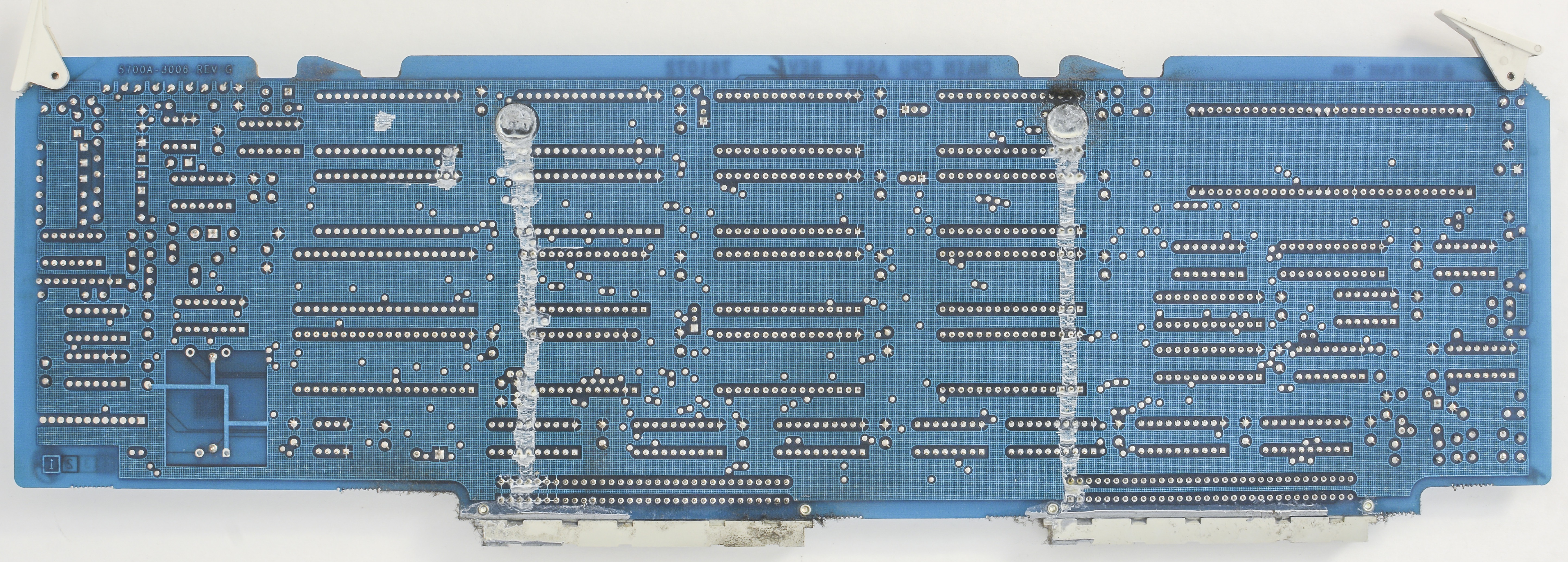
A20 Processor PCA
Service manual lists all 5700 series calibrators as ones with same hardware except processor board A20, which is detailed as:
| Board number | Calibrator model | Fluke order Part.No | Revision |
|---|---|---|---|
| A20 | 5700A Series I | 1591070 | 108 |
| A20 | 5700A Series II | 1639013 | 107 |
| A20 | 5720A | 1626228 | 108 |
Our A20 5700A-3006 board is P/N 761072, with Revision F marked by ink, and Rev.G by PCB copper etch.
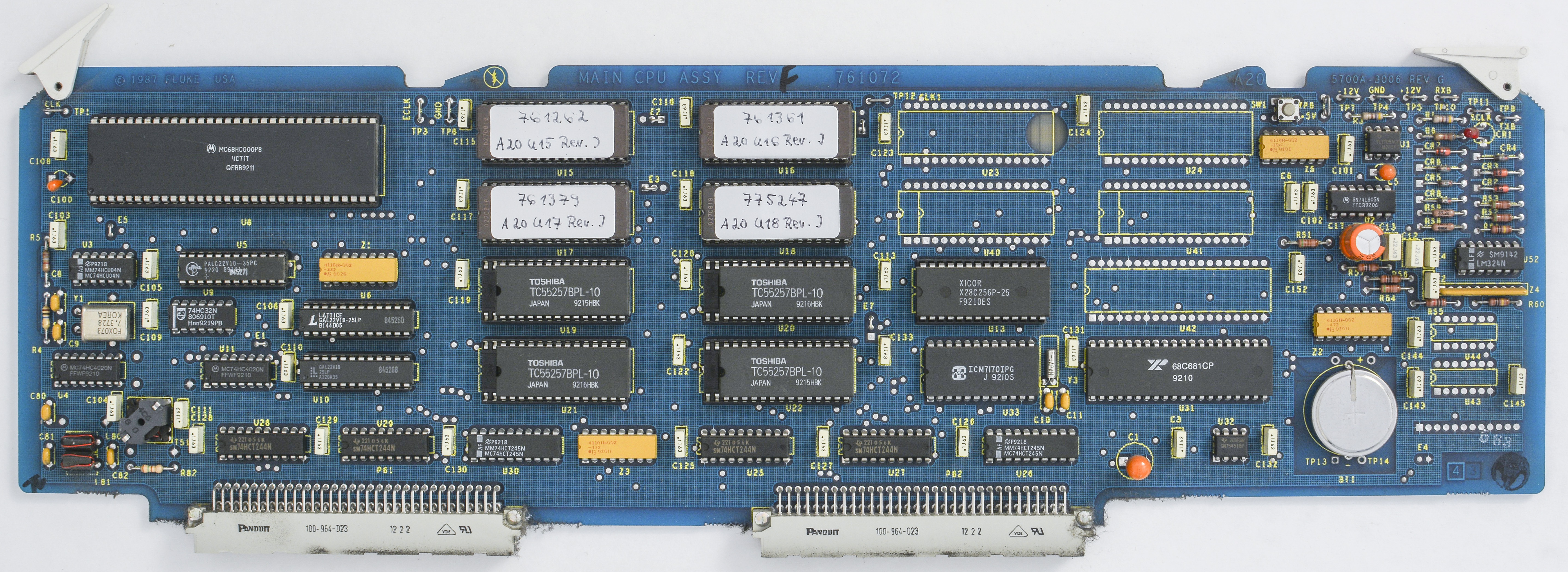
CPU board is based on well-known and popular Motorola MC68HC000P8 processor, tied to 28C256 EEPROM, four firmware 27010 EPROMs and 128K of SRAM (four TOSHIBA TC55257BPL-10). There are option sockets for additional 2 × 27010 EPROM and extra 2 × 32K RAM. Firmware stickers say it’s Revision J. We will reed these D27C010 ROMs later on programmer. There is bunch of 74-series logic around and few 22V10 PAL and GALs. Main clock is provided to CPU from 7.3728MHz XO.
3V Lithium battery BT1 backup only realtime clock, based on Intersil ISL7170, which is good news after all the calibration data lost shenanigans on HP 3458A, Tektronix 7000 scopes and such. Calibration data is likely live happily in socketed U13, Xicor X28C256P.
Tactile switch SW1 located near top right corner is for CPU RESET controller, which is generated old known TL7705 IC. Same one we saw before on Keithley 2001 and 2002. Non-reset state is shown by lonely red LED CR1. If it’s lit – we good to go.
Interconnection with backplane done via pair of 64-pin dual row connectors. Lonely LM324N general purpose opamp is used to monitor fans health and drive fan alert signal in case of fan failure. Board also have load of test points, which we can check if necessary.
| Test point name | Signal name | Measured |
|---|---|---|
| TP1 | CLK | |
| TP3 | ECLK | |
| TP4 | GND | Ground 0V |
| TP5 | +12V | |
| TP6 | +5V digital | |
| TP7 | -12V | |
| TP8 | GND | |
| TP9 | TXB serial transmit | |
| TP10 | RCVB serial receive | |
| TP11 | SCLK | |
| TP12 | CLKI | |
| TP13 | +BATT RTC battery | |
| TP14 | -BATT RTC battery |
Also interesting to note UART controller 68C681 U31 which have serial interface at RCVB (TP10) and TXB (TP9) points. Likely this is main serial interface between outguard and inguard domains of MFC.
A21 Rear panel PCA
A22 Mains power transformer assembly
Firmware
Main firmware stored in four 27C010-200V10 ROMs, U15-U18 positions on A20 processor board. Calibration ROM is stored in non-volatile Xicor X28C256P-25. Calibration ROM does not depend on battery, it’s simple SRAM, so no calibration data corruption even for old units, unless ROM itself become bad (which is rare, but still happens).
| Firmware version | Combined binary | U15 ROM | U16 ROM | U17 ROM | U18 ROM |
|---|---|---|---|---|---|
| Model 5700A Series I, Rev.J, Build 11/15/93 10:52:39 | 5700A Rev.J binary | U15 ROM CHK:00922940 | U16 ROM CHK:0081BC9D | U17 ROM CHK:00B940B6 | U18 ROM CHK:009E9081 |
Combined binary images were merged using simple python tool:
# xDevs.com Firmware combine tool
# https://xdevs.com/fix/f5700a

import os
with open('5700a_s1_u15_761262_revj_00922940.bin','rb') as a:
    with open('5700a_s1_u16_761361_revj_0081bc9d.bin','rb') as b:
        with open('5700a_s1_u17_761379_revj_00b940b6.bin','rb') as c:
            with open('5700a_s1_u18_775247_revj_009e9081.bin','rb') as d:
                with open('5700_J_FULL.bin','wb') as x:
                    for cnt in range(0, 262144):
                        x.write ("%s%s" % (b.read(1),a.read(1) ) )
                    for cnt in range(0, 262144):
                        x.write ("%s%s" % (d.read(1),c.read(1) ) )
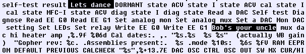
Quick glance on result file revealed some hidden strings. Easter eggs? :)
Easy to read and backup calibration ROM as well, using external programmer, such as TL866. It’s wise to backup calibration ROM before attempting own re-calibration or sending unit to service, just in case.
Calibration ROM dump:
| Calibration ROM | Dump |
|---|---|
| Initial 5700A Rev.J CAL ROM, calibration 2012 | Binary CHKSUM: 006D8EA5 |
Inguard microprocessor ROM (27C256) located on A17 PCBA, position U64:
| Inguard ROM | Dump |
|---|---|
| Initial 5700A Rev.A In-guard ROM P/N 881698 | Binary CHKSUM: 002E740A |
Many other instruments firmware dumps are available on xDevs.com documentation site
If you have another Fluke 5700A firmware (or any other instrument firmware), please feel free to upload here.
Repairs and diagnostics
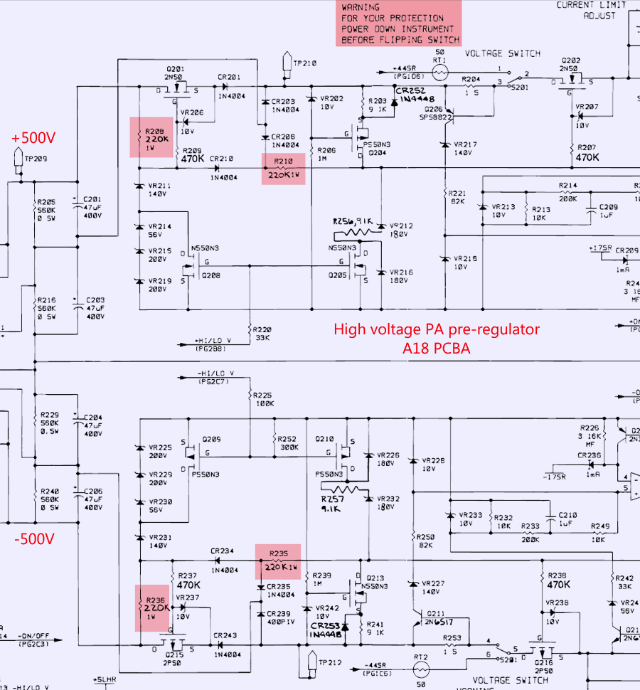
A18 High voltage/High current PA
Few 1W 220K resistors were measured low (~90 KΩ) and were replaced with 3W 220K, as expected by Fluke BOM. These resistors set current and affect control for pass transistors on high-voltage supply regulator for PA.
Below is schematic fragment with marked components.
Other possible 5700A issues, reported by community
Tweaks and tricks
Calibrator’s rear air filter must be removed and cleaned at least every 30 days, or more frequently if the unit is in a dusty environment. Damage to the instrument can occur if air intake blocked / clogged for extended period of time. It’s important to keep intake airflow clean and open to ensure calibrator performance.
Disabling VFD to save it’s life during remote operation
Calibration
The Fluke 5440A DC Voltage Calibrator was introduced some 35 years ago, in 1982 and was the first instrument to have Artifact Calibration functionality. This Artifact Calibration uses an external 10VDC reference and decade divider as traceable standards to adjust internal ranges. Comparisons are made using an external null detector, and through this process internal references and dividers are calibrated.
The Fluke 5700A further expanded on the capability of the 5440A/5440B Artifact Calibration techniques. The expansion included the additional AC voltage functionality, fixed resistance and also DC and AC current. The Model 5720A is same unit with higher performance and better stability. Inside the 5700A and 5720A there is a null detector built using integrating multislope ADC for making precise comparison and high-stability divider for scaling between different ranges.
The inclusion of the measurement system in the instrument being calibrated eliminates the need for the operator to manually calculate difference between the externally applied voltages and internally generated voltages, and allows the instrument software to automatically null the adjustment and remove errorss. The null detector zero is also calibrated and made traceable by periodic adjustment against an internal short.
Here’s list of external standards used for calibration of this 5700A:
| Standard used | Nominal Value | Uncertainty Limit | MFC specs affected |
|---|---|---|---|
| Fluke 732B | 10 VDC | ±1.5 ppm | DCV,ACV,DCI,ACI |
| Fluke 742A-1 | 1 Ω | ±10 ppm | Resistance 1Ω, 1.9Ω |
| Fluke 742A-10k | 10 kΩ | ±4 ppm | ACI,DCI, 10Ω to 100 MΩ |
Table : Standards for Calibrating 5700A/5720A Series II
Actual standards used (August 2016):
| Fluke 5700A CAL | Standard value | Deviation |
|---|---|---|
| 10.000000 VDC | 9.9999323 VDC | +0.0 ppm |
| 10.000080 kΩ | 10.0000505 kΩ 4W | -0.2 ppm |
| 1 Ω | 0.99997505 Ω 4W | +23.1 ppm |
Performance verification
Here are resistance measurement results obtained from 24-hour calibrated 3458A DMM with pair of Fluke 5440 test leads. Settings of DMM are: NPLC 100, DELAY 1 and OCOMP ON for Rvalues <1MΩ, AZER ON.
| Fluke 5700A OHM (actual) | 3458A Measurement value | Deviation |
|---|---|---|
| 0 Ω (0.000000) | 0.00000288 Ω 4W | +2.88 ppm |
| 1 Ω (0.9998249) | 0.9997906 Ω 4W | -34.3 ppm |
| 1.9 Ω (1.8995690) | 1.8994901 Ω 4W | -41.52 ppm |
| 10 Ω (9.999934) | 9.99985546 Ω 4W | -7.85 ppm |
| 19 Ω (18.999101) | 18.9989842 Ω 4W | -6.14 ppm |
| 100 Ω (100.00187) | 100.001919 Ω 4W | +0.49 ppm |
| 190 Ω (189.99523) | 189.995162 Ω 4W | -0.356 ppm |
| 1000 Ω(0.9999919K) | 0.99999252 kΩ 4W | +0.62 ppm |
| 1900 Ω(1.8999967K) | 1.89999877 kΩ 4W | -1.08 ppm |
| 10 kΩ (10.000080K) | 10.0000968 kΩ 4W | +1.68 ppm |
| 19 kΩ (18.999695K) | 18.9997209 kΩ 4W | +1.36 ppm |
| 100 kΩ(100.00133K) | 100.001386 kΩ 4W | +0.56 ppm |
| 190 kΩ(189.99286K) | 189.993439 kΩ 4W | +3.04 ppm |
| 1 MΩ (1.0000017M) | 1.00000047 MΩ 4W | -1.22 ppm |
| 1.9 MΩ(1.8999562M) | 1.89994836 MΩ 4W | -4.12 ppm |
| 10 MΩ (9.999382M) | 9.9990808 MΩ 4W | -30.12 ppm |
| 19 MΩ (18.999034M) | 18.999738 MΩ 4W | -37.10 ppm |
| 100 MΩ(100.00848M) | 100.02146 MΩ 2W | +129.79 ppm |
Resistance function stability verification
Since January 2017 calibration against freshly calibrated IET SR104, SRL1 and Fluke 732B, this 5700A was monitored and ran thru calibration check procedure, to establish stability levels for it’s functions. Here’s presented data of stability study for resistance function:
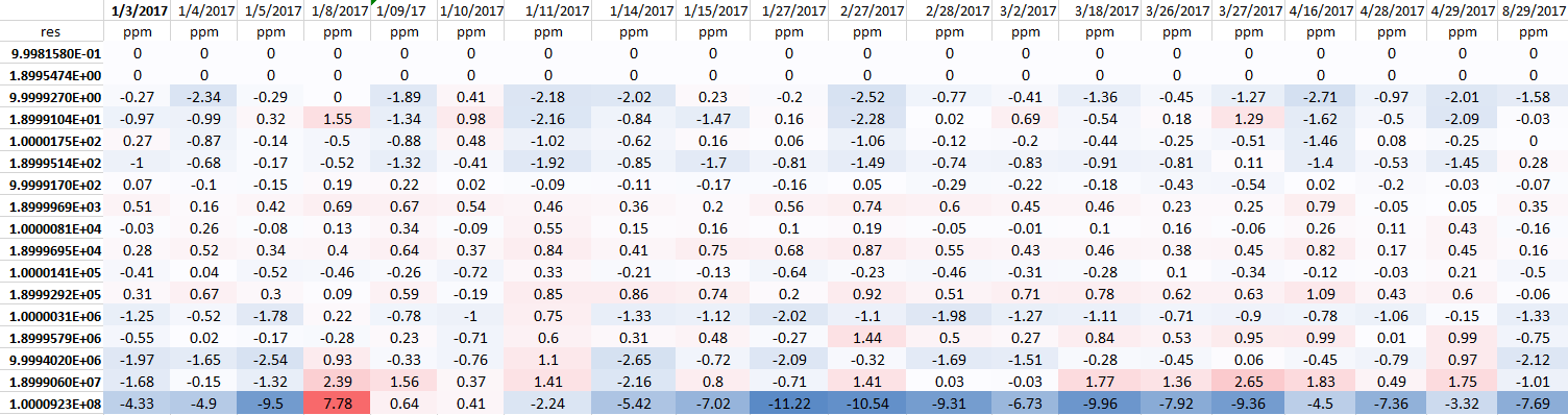
Main function ranges, such as 1 KΩ, 10 KΩ and 100 KΩ are very well under 1ppm error from calibrated value. This is great result, considering than ambient temperature or humidity in lab was not very tightly controlled. Unit was powered 24/7 for period till May, and turned off for summer time. Last calibration check point August 29 was ran after 40 hour warming up.
Here is also overall calibration check results, on key internal references:

DCV Noise evaluation
DCV Linearity evaluation
Tempco evaluation
Connecting 5700A to 5220A current amplifier
Currently I don’t have native Fluke 5725A amplifier, so much older 5220A amplifier will be used to boost current range capability of calibrator system. As no interface cable was included, we have to make one ourselves. For this task Fluke Y5002 cable document will be used as reference, as well as schematics from Fluke 5700A Series I Service manual.
Fluke Y5002 Interface cable assembly document, May 1979
A21 Rear Panel PCA schematics page from 5700A Series I SM
Remote GPIB control software
Restoration summary
Projects like this are born from passion and a desire to share how things work. Education is the foundation of a healthy society - especially important in today's volatile world. xDevs began as a personal project notepad in Kherson, Ukraine back in 2008 and has grown with support of passionate readers just like you. There are no (and never will be) any ads, sponsors or shareholders behind xDevs.com, just a commitment to inspire and help learning. If you are in a position to help others like us, please consider supporting xDevs.com’s home-country Ukraine in its defense of freedom to speak, freedom to live in peace and freedom to choose their way. You can use official site to support Ukraine – United24 or Help99. Every cent counts.
Modified: Nov. 15, 2024, 1:12 a.m.
References
- KO4BB's manual section for Fluke
- Tech Data: FlukeCare™ Accreditation Calibration Program
- AN: Establishing traceability for a high-performance AC/DC transfer standard
- Fluke Electrical Calibration Workload Matrix
- Fluke 5700A/5720A Series II MFC Service Manual with schematics
- AN: Fluke Calibration Certificates
- The Impact of the New SI on Industry, Jeff Gust, Fluke
- AN: Artifact calibration theory and application on Fluke 5730A
- Calibrating Precision Multimeters Using a Characterized Multifunction Calibrator, Gary Bennett, Fluke
- The effectiveness of Artifact Calibration in computing internal resistance values
- Thin Film designs for 1000V AC Range resistors in 792A and 5790A
- Supporting New Calibrators with Existing Equipment
- An evaluation of the 5700A Series II Artifact Calibration
- An Assessment of Artifact Calibration Effectiveness for a MFC 5700A, Les Huntley, Fluke
- A Preliminary Assessment of the Effectiveness of 5700A Artifact Calibration, Les Huntley, Metrologist, Inc.
- Enhancing reliability in a MFC using Thermal Design
- A study of and recommendations for applying the false acceptance risk specification of Z540.3
- Having confidence in specifications, David K. Deaver, Fluke
- AN: An Evaluation of Artifact Calibration in the 5700A Multifunction Calibrator
- Updated Evaluation of Calibration Test Point Selection for Fluke 57XX products
- AN: How cables and connectors impact measurement uncertainty
- Fluke Precision Calibrator Upgrades
- AN: Understanding specifications for precision multimeters
- How to Maintain Your Confidence (in a World of Declining Test Uncertainty Ratios), David K. Deaver, Fluke
- Richi's Lab teardown of Fluke thermal RMS sensor