Contents
- Intro
- Disclaimer
- Manual references
- Teardown and repair
- Firmware versions
- DCV Noise evaluation at shorted inputs
- Noise performance verification
- Temperature stability study
- Calibration and accuracy verification
- GPIB code references
- VFD replacement options update
- Summary
Intro
Before this article, we had no chance to play with Fluke 6½-digit benchtop multimeters, but this article target the issue now. And as usual, meter acquired for the article is dead broken and non-functional. It makes the whole thing yet more interesting to investigate and troubleshoot. Fluke Model 8846A DMM in question is higher-end 6½-digit benchtop multimeter, able to provide lot of funtionality in compact half-rack form factor.
This multimeter design is also known as Tektronix DMM4050 and DMM4040 (lower end variant, like Fluke 8845A). They are very same meters running on same hardware, but with different firmware and configuration.
Key feature highlights:
- 6½ digit resolution for all key functions, maximum input voltage 1000V.
- 20% overrange except 1 kV and 10 A ranges.
- Best DCV absolute accuracy 24 ppm, speed up to 50 kSPS (995 SPS to GPIB).
- A/D Linearity 2 ppm of measurement + 1 ppm of range, input bias current <30 pA at +25 °C
- Dual display for signal analysis
- 100 µA to 10 A current range (protected with replaceable HRC fuses)
- 400 mA range (available in software version 1.0.700.18 or newer)
- 2-wire and 4-wire resistance ranges from 10 Ω to 1 GΩ
- Measure frequency, period, capacitance and temperature
- USB 2.0 memory drive port
- GPIB, RS232 and LAN interfaces for remote connection/control
- Support Fluke 45 and Keysight 34401A protocol emulation
- Graphical display with data recorder mode, deviation statistics, histogram view
Take a look on what accuracy meter have to offer us:
| Measurement Function | Range | Best accuracy, 30 day, within ±1 °C TCAL |
|---|---|---|
| DC Voltage | ±100 mV to 1000 V | ±24 ppm of reading + 5 ppm on the 10V range, High-impedance mode for 100mV-10V ranges |
| DC Current | ±100 µA, ±1 mA, ±10 mA, ±100/400 mA, 1A, 3A, 10A | ±500+ ppm |
| AC Voltage | 10 Hz – 30 kHz, 1 V, 10 V, 19 V, 100 V | ±600+ ppm |
| AC Current | 100 µA, 1 mA to 1A, 10 A @ 10 Hz to 10 kHz | ±1000+ ppm |
| Resistance | 10 Ω – 1 GΩ | ±100+ ppm |
| Capacitance | 1 nF – 100 mF | ±1% except 1nF and 100mF range |
| Temperature (RTD) | -200 °C to +600 °C | ±0.06% to 0.22%, test current 1mA |
| Continuity | Selectable, 1/10/100/1000 Ω | ±0.01% at 1000 Ω |
| Diode test | Selectable, 100 µA or 1 mA and 5V or 10V | ±0.01% |
Table 1: 8846A function list
We also got old long-obsolete 8842A 5½-digit multimeter, but that is the story for another article. Together all Fluke meters almost look like an invasion to our lab space, but yet they are still far outnumbered by stashes of Keithley units xDevs.com have. :)
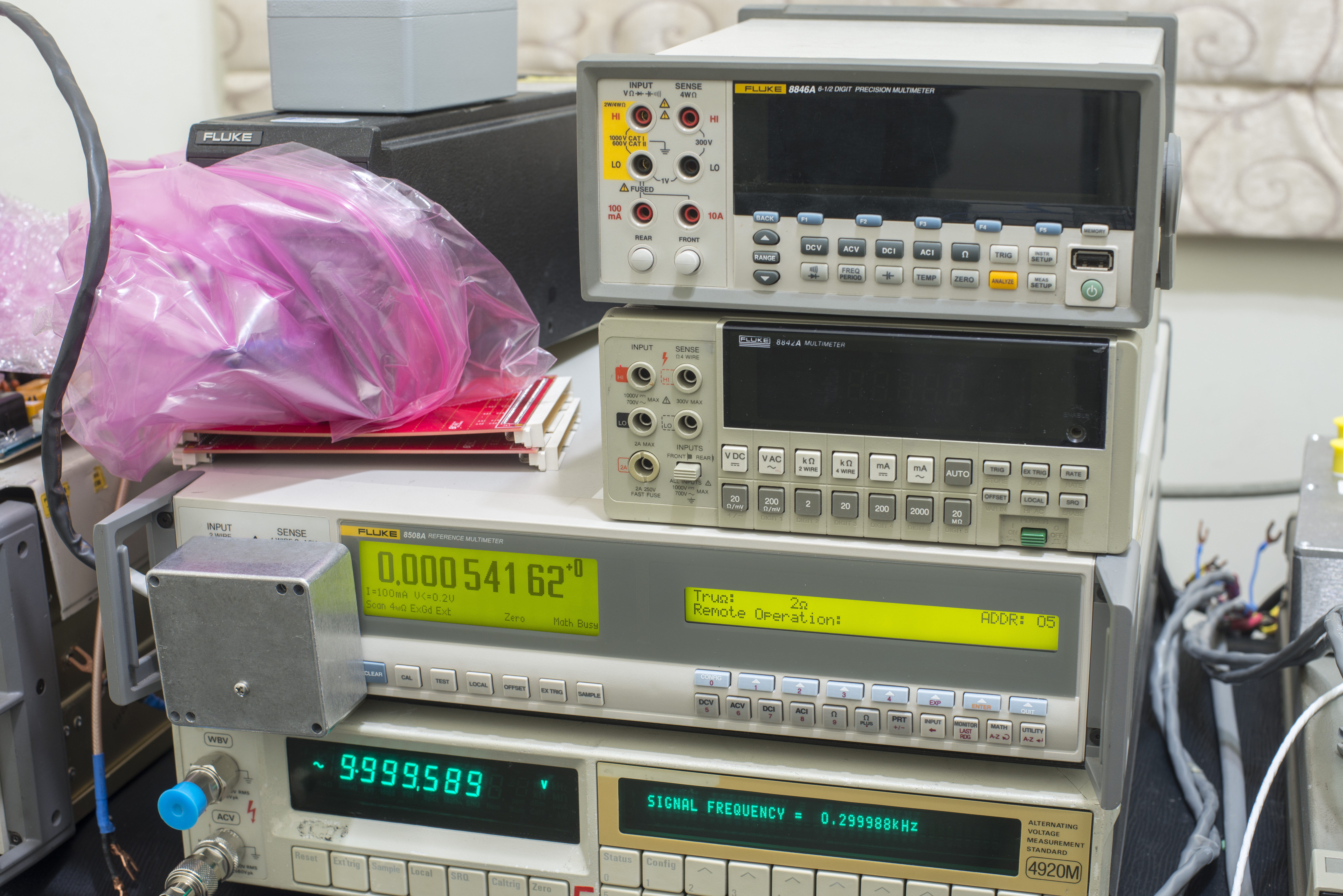
Image 1: Multiple Fluke DMM generations in single photo
Reference multimeter 8508A you can see on the photo above is a temporary visitor to help with testing our recent lab upgrade, Fluke 5720A rebuild project. Full worklog of that large and expensive experiment will be published on later date.
Back to 8846A, visual inspection revealed damaged power input block, that combine mains receptacle, electrical power switch and fuse holder/voltage selector in a single plastic assembly. It have missing tab to keep it secured to chassis, but that is not the main problem with this meter.
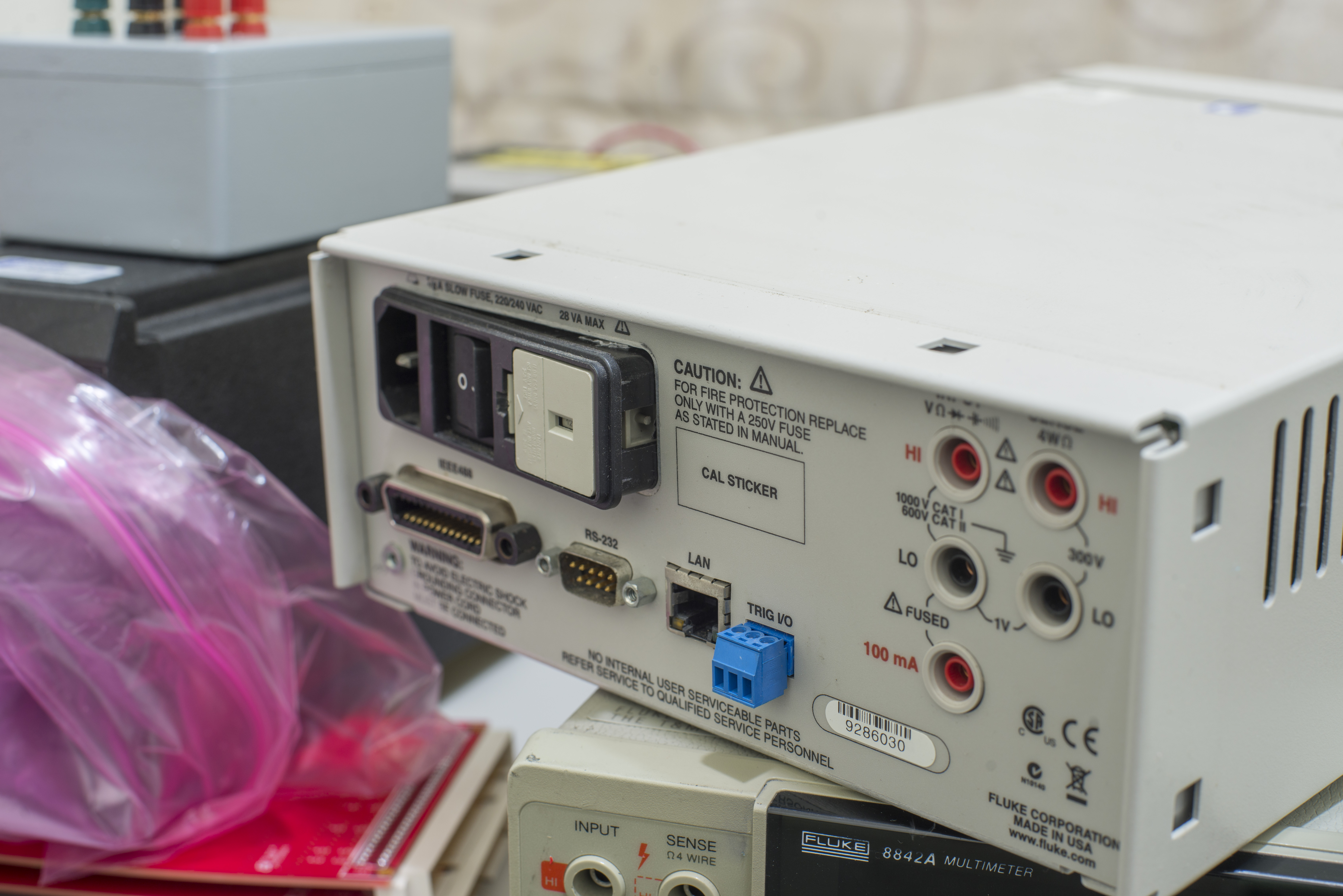
Image 2: 8846A rear side in condition as received
This is older 8846A version, still with for 100mA range and without DCV ratio function. Newer meters with firmware version 2.xx have next items added:
New measurement functionality:
- increased V dc reading rate to 1000 readings per second, for improved measurement throughput in an ATE system
- increased milliamp input range to 400 mA, to cover a wider range of measurements through a single input
- DCV:DCV ratio, making it possible to do relative comparisons of two DC voltage test points
New features include:
- added DCI and DCV dual measurement, making it easy to calculate power dissipation and simplifying battery power management testing in portable devices
- create and store power-up instrument configuration, so you can configure your meter once and keep the setup, even if power is turned off or lost
- Fluke 8842A command emulation mode
Firmware update was available from Fluke official web-site, but later was removed :(.
Disclaimer
Redistribution and use of this article, any part of it or/and any images or files referenced in it, in source and binary forms, with or without modification, are permitted provided that the following conditions are met:
- Redistributions of article must retain the above copyright notice, this list of conditions, link to this page (/fix/f8846a) and the following disclaimer.
- Redistributions of files in binary form must reproduce the above copyright notice, this list of conditions, link to this page (/fix/f8846a), and the following disclaimer in the documentation and/or other materials provided with the distribution, for example Readme file.
All information posted here is hosted just for education purposes and provided AS IS. In no event shall the author, xDevs.com site, or any other 3rd party, including Fluke/Tektronix be liable for any special, direct, indirect, or consequential damages or any damages whatsoever resulting from loss of use, data or profits, whether in an action of contract, negligence or other tortuous action, arising out of or in connection with the use or performance of information published here.
If you willing to contribute or add your experience regarding instruments repairs or provide extra information, you can do so following these simple instructions
Manuals and documentation
8845A/8846A Calibration Manual, January 2007, Rev. 1, 11/07
8845A/8846A Calibration Manual Supplement, Issue 5
8845A/8846A Programmers Manual, September 2006, Rev. 2, 6/08
8845A/8846A Programmers Manual Supplement, issue 2
8845A/8846A 8845A/8846A Programmers Supplement, issue 2
8845A/8846A Safety Information
8845A/8846A Instrument Security Procedures
Y8846A Rack-Mount Kit instruction
Tektronix DMM4040/DMM4050 User’s manual
8845A/8846A Digital Multimeters accessory guide
Fluke 8845A/8846A statistics and histograms
Data logging on the Fluke 884X
8845A/8846A and 8808A brochure
Fluke 8845A/8846A Extended Specifications, Rev 02
2×4 wire resistance simplifies precision measurements
Tek DMM4020, DMM4040, and DMM4050 Connectivity Installation Manual
Tek DMM4040 and DMM4050 Programmer manual
There is no service manual or schematics available for these meters.
Teardown and repair
So issue with this meter is a clear one – upon powering up it display pretty “Fluke DMM www.fluke.com Initializing…” and then nothing happens. Booting time for these meters is usually less than 20 seconds.
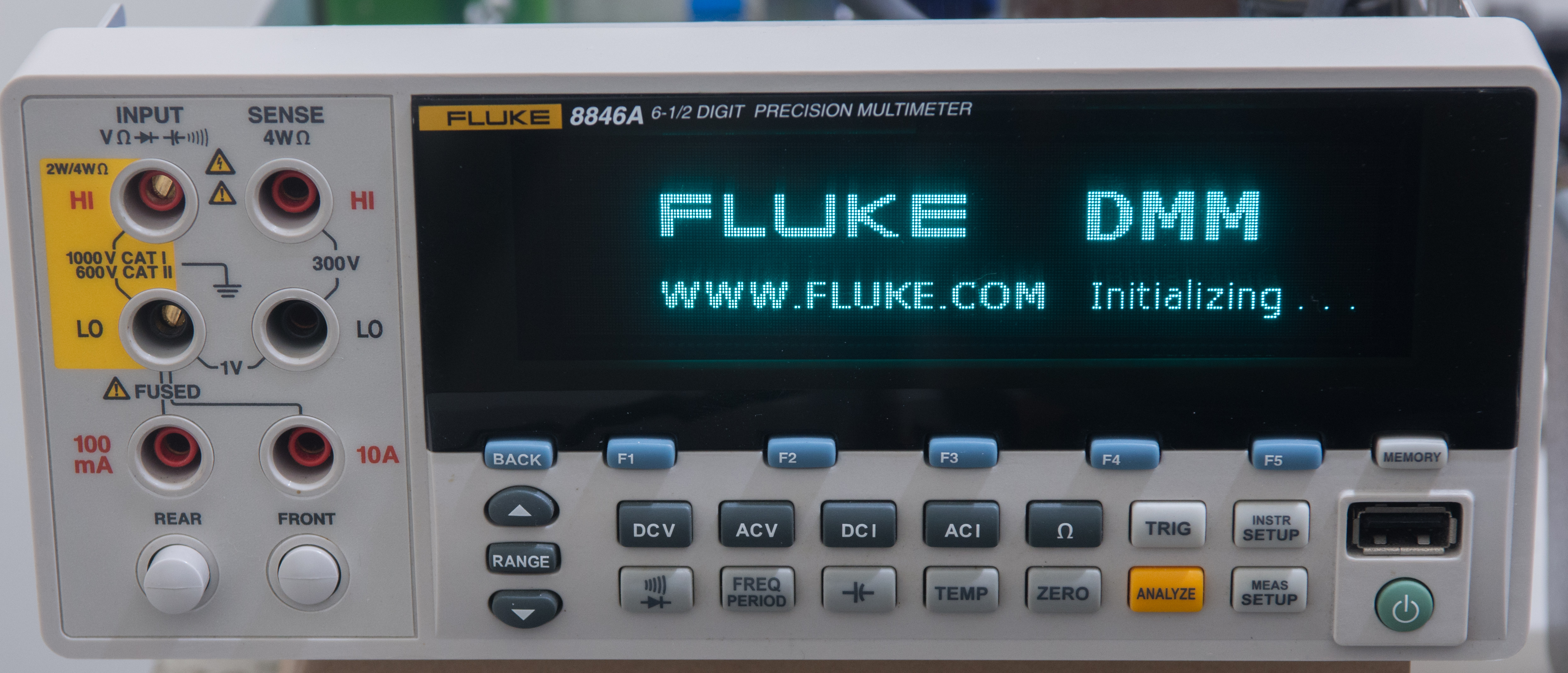
Image 3: Initialize boot screen on which faulty meter hangs indefinately
This indicate either power supply issues, or main processor issues. Well, good news – at least expensive dot-matrix graphics VFD screen is fully working. Front panel replacement for this Fluke would cost nearly half of the new meter cost.

Image 4: VFD front panel and keypad PCBA.
Display is custom Noritake Itron chip in glass design, quite expensive. Benefit of this type vacuum displays is easy integration, as you do not need to fanout high voltage drivers and controller chips on the PCB. Everything is embedded in glass, reducing amount of pins to connect significantly.
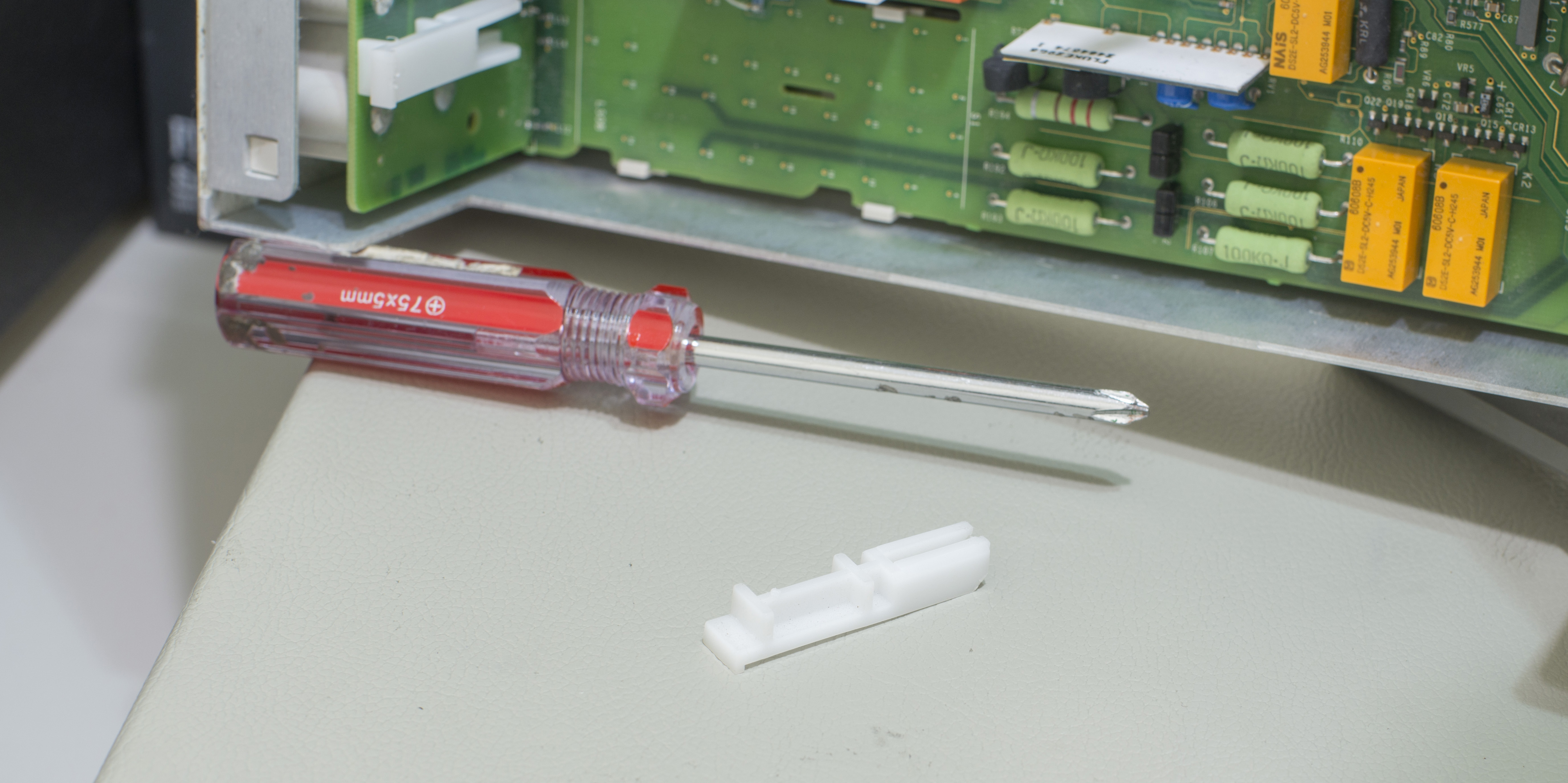
Image 5-6: Bottom side with fuse replacement door visible and plastic part fallen out after disassembly
Just four screws that hold metal cover, and we are in.

Image 7: Inside design of the multimeter
Transformer have some serious amount of rust. There is also missing RTC battery. No other visible issues at first glance.
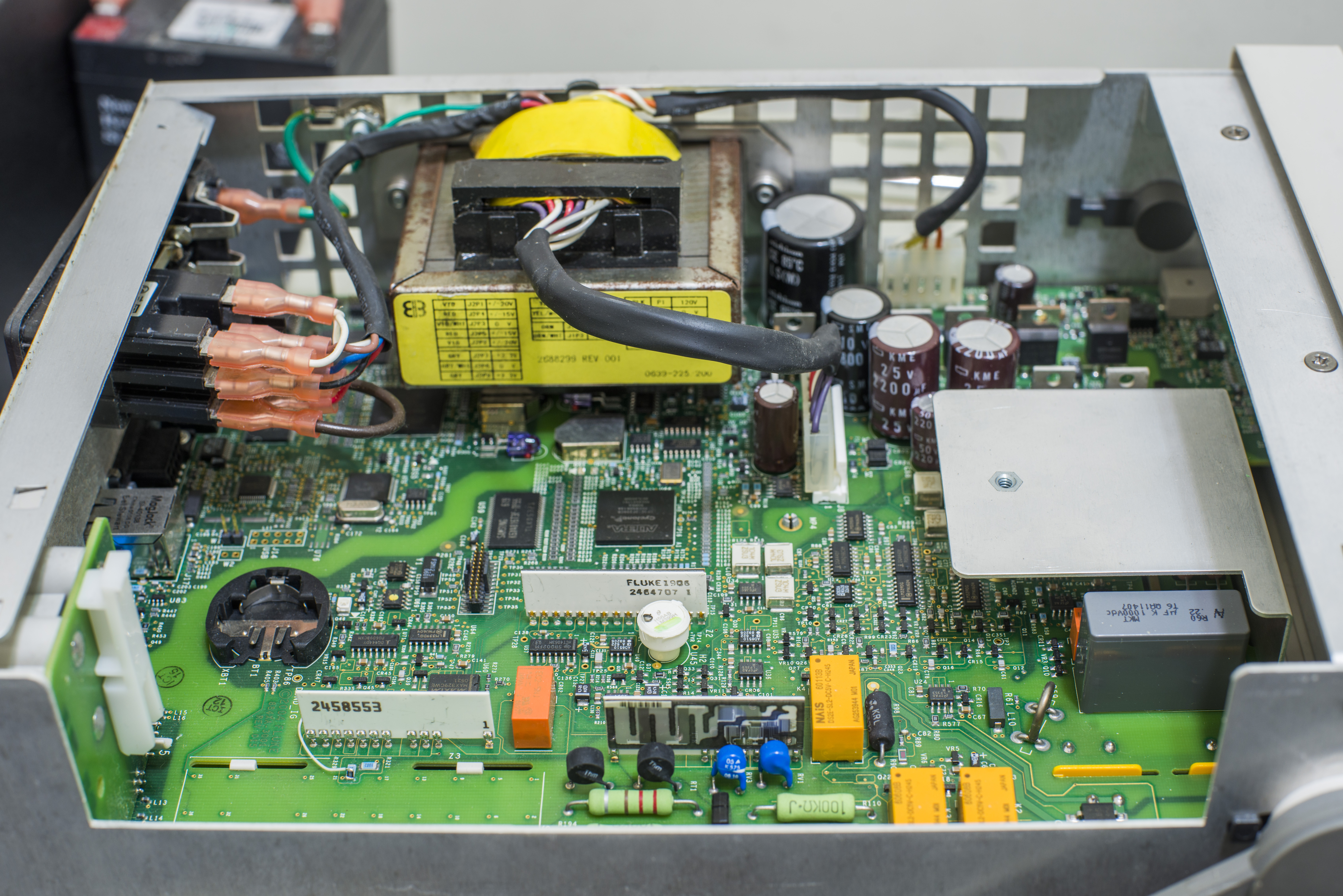
Image 8: Another angle view. Visible bodge wire around one of resistor networks
Capacitors are nice top-tier brand ones, however they still must be replaced, this meter dated back to early 2006, so they are at end of life already.
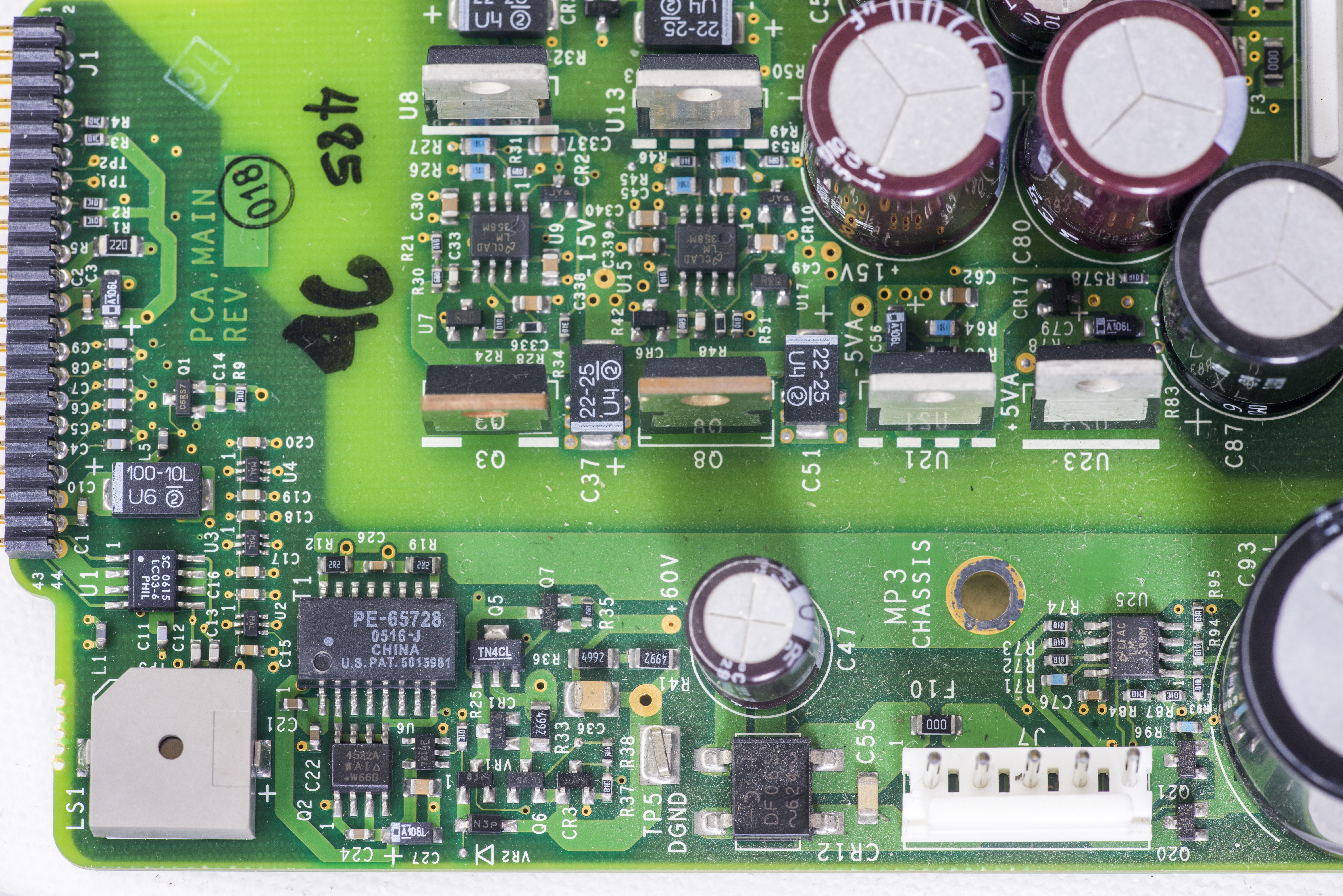
Image 9: Visible bodge wire around one of resistor networks
Little gray box in the corner is piezoelectric buzzer. U1 near it is LC03-6 from Semtech, protection TVS diode block for USB2.0 port on front panel.
Let’s take a look on outguard power. VFD high-voltage SMPS converter looks ok. I checked output voltage, and found desired +60VDC, no problem here. Si4532A is MOSFET pair that drive Pulse transformer to generate high voltage. Little SOT23-5 is likely the pulse controller for this regulator.
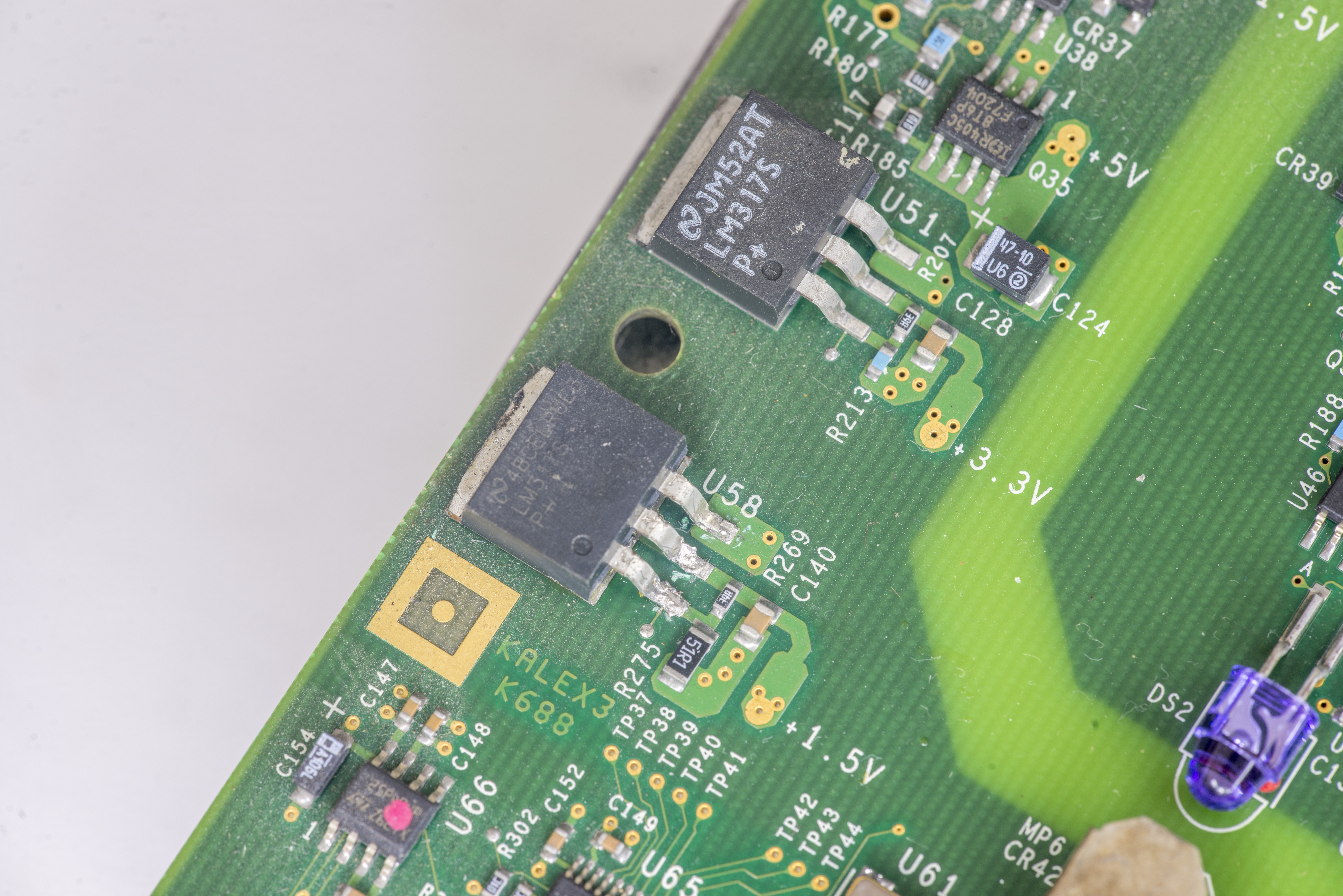
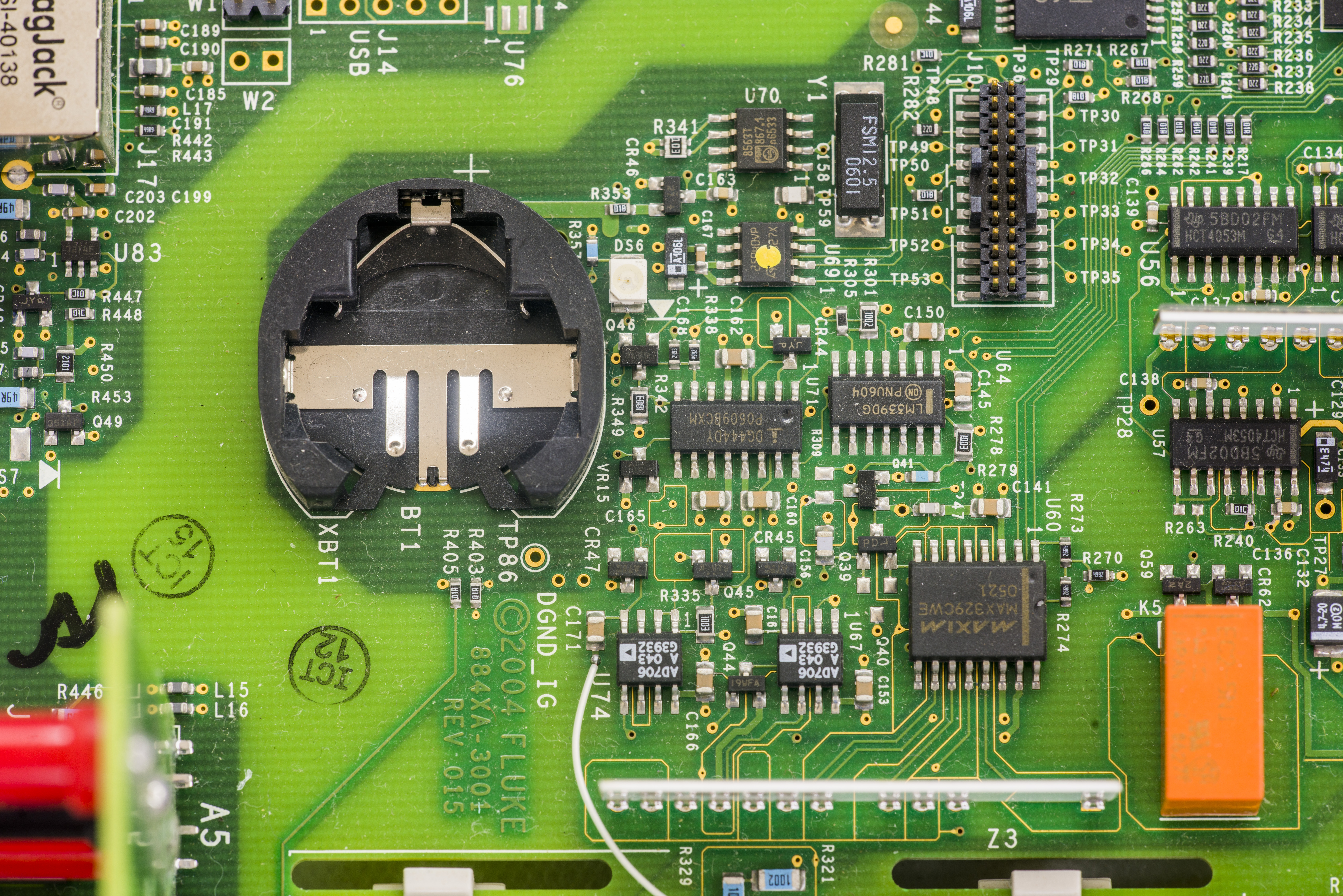
Image 10-11: LM317S with probe marks and empty battery holder area
Now outguard supply and inguard battery-powered RTC. Kinda strange that RTC is in inguard domain, perhaps that battery also powers some NVRAM to store temporary readings?
LM317S U58 seen better days, but seem to be still operating normally, outputting +1.5VDC for digital domain supply.
Next to battery holder we see PCB logo from Fluke, with year 2004. That is date of the design, so this meter was built just few years after the initial design done. Since it’s same platform used for both 8845A and 8846A models, PCB is just marked 884×-3001. PCB revision is 015. Newer models have debug stuff removed, but this one still have populated test headers such as Trace port connector J10 for ALTERA FPGA development and test LEDs like DS6 next to battery.
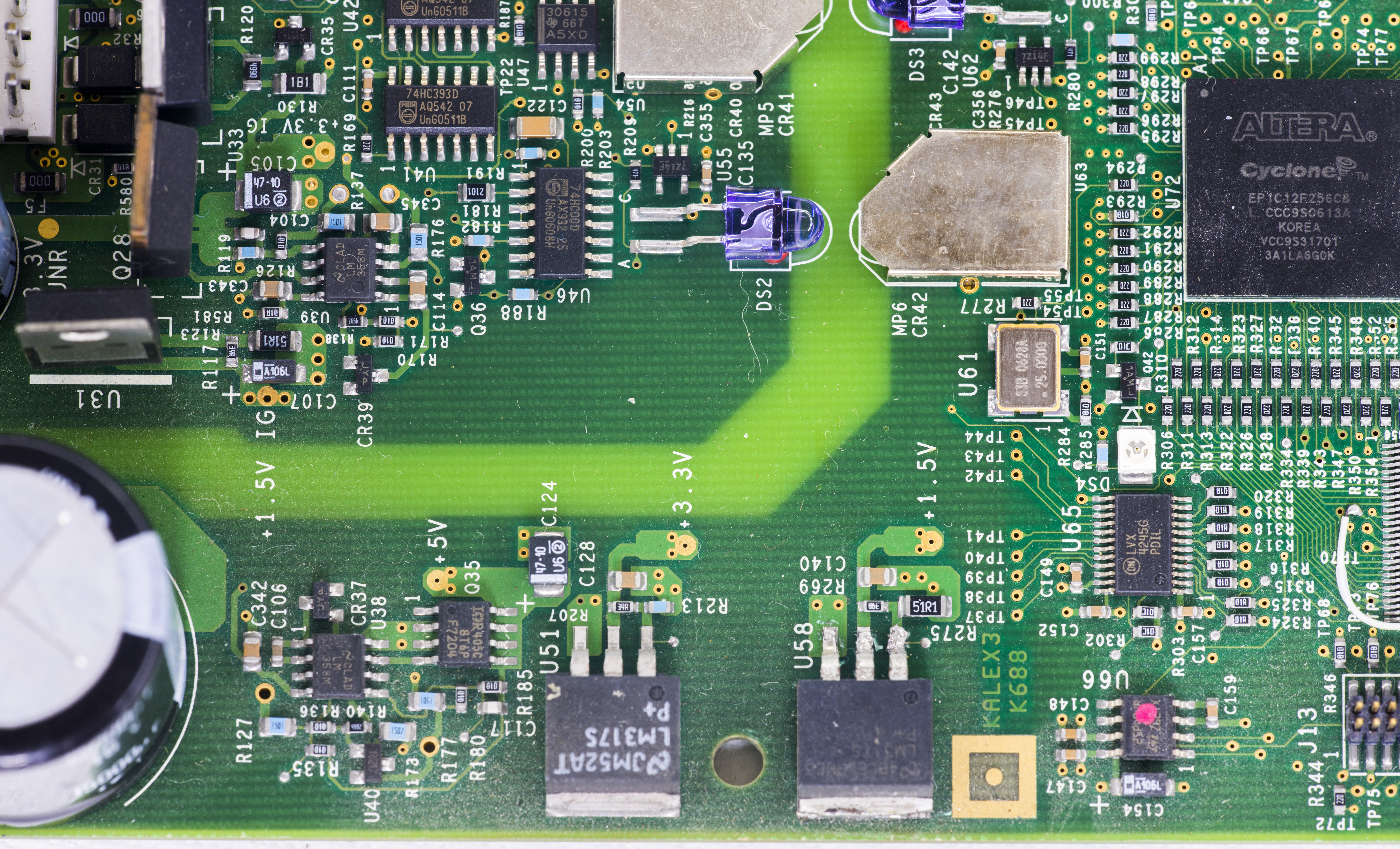
Image 12: Outguard power together with outguard FPGA U72 and discrete optocoupler interface
PCB designer carefully added test points labels for main voltages with open solder mask spots to allow easier troubleshooting and service. At least we know what voltage to expect, without looking for service manuals.
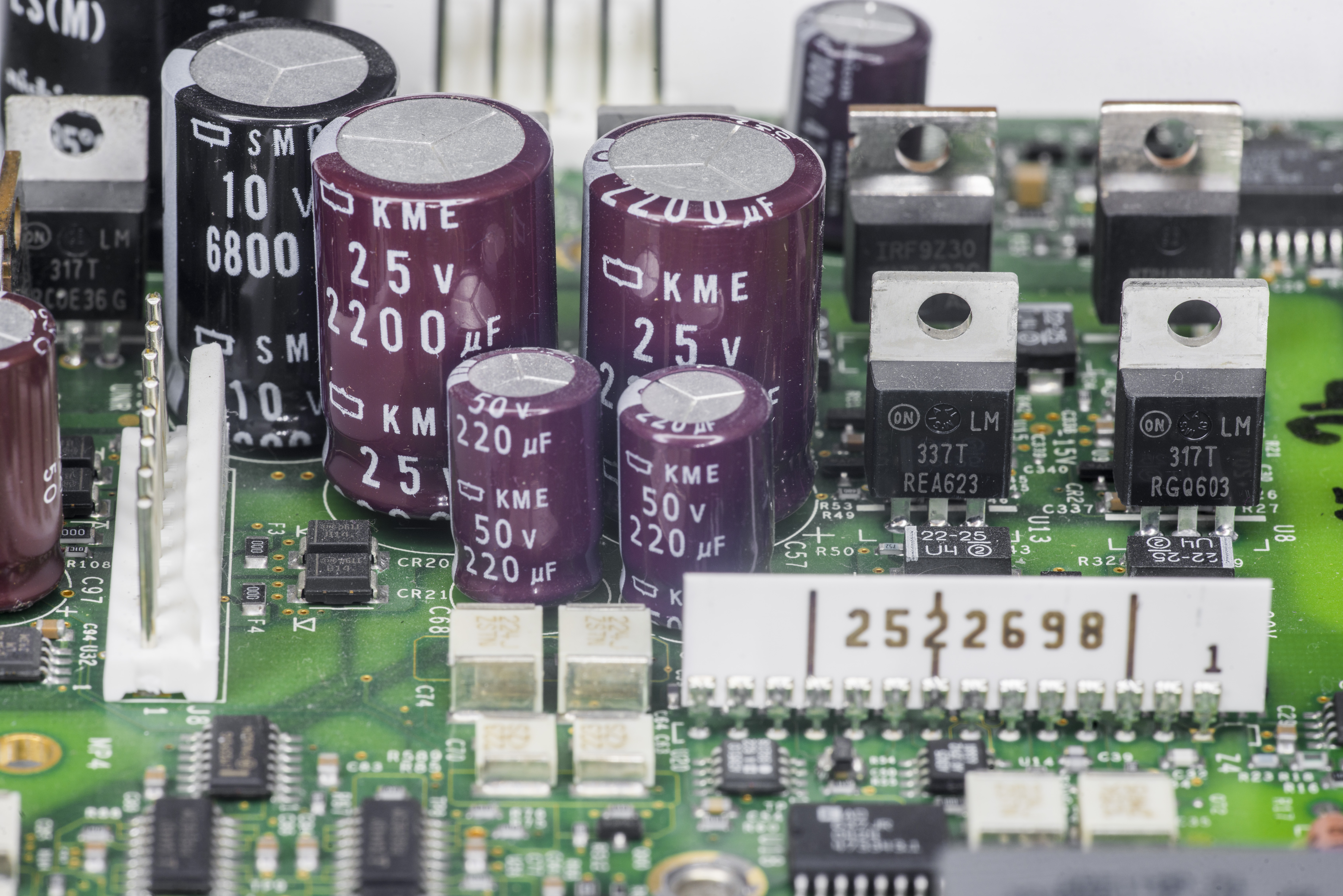
Image 13: Inguard supply capacitors and regulators
Quality capacitors here, Chemicon KME series rated for +105 °C and SMG +85 °C. Today KME’s are replaced with KMG. Just like many other benchtop multimeters, there are plenty LM337 and LM317’s found in linear regulator areas. Large white SIP package with 2522698 number is ceramic resistor network for AC section of the multimeter.
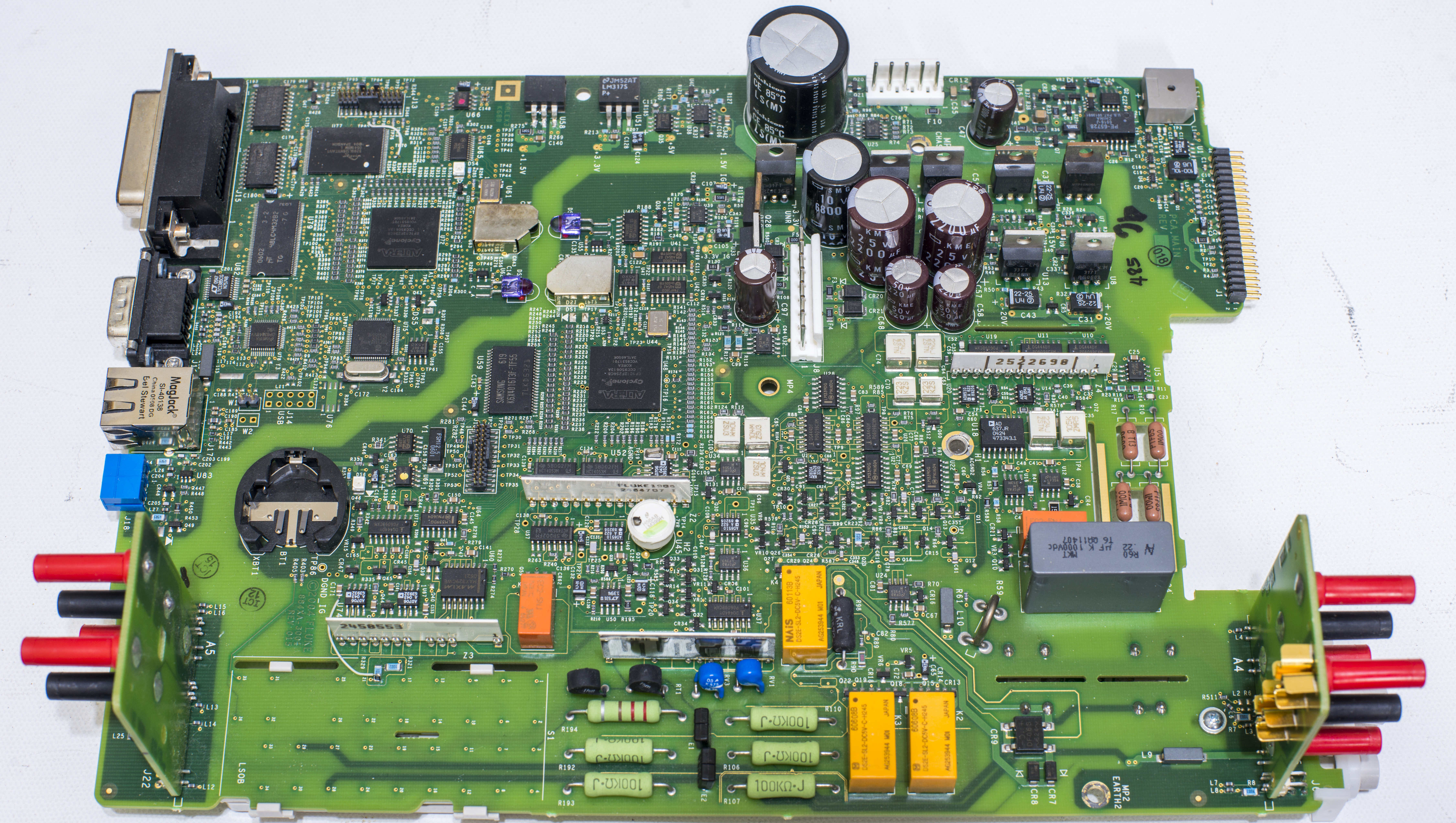
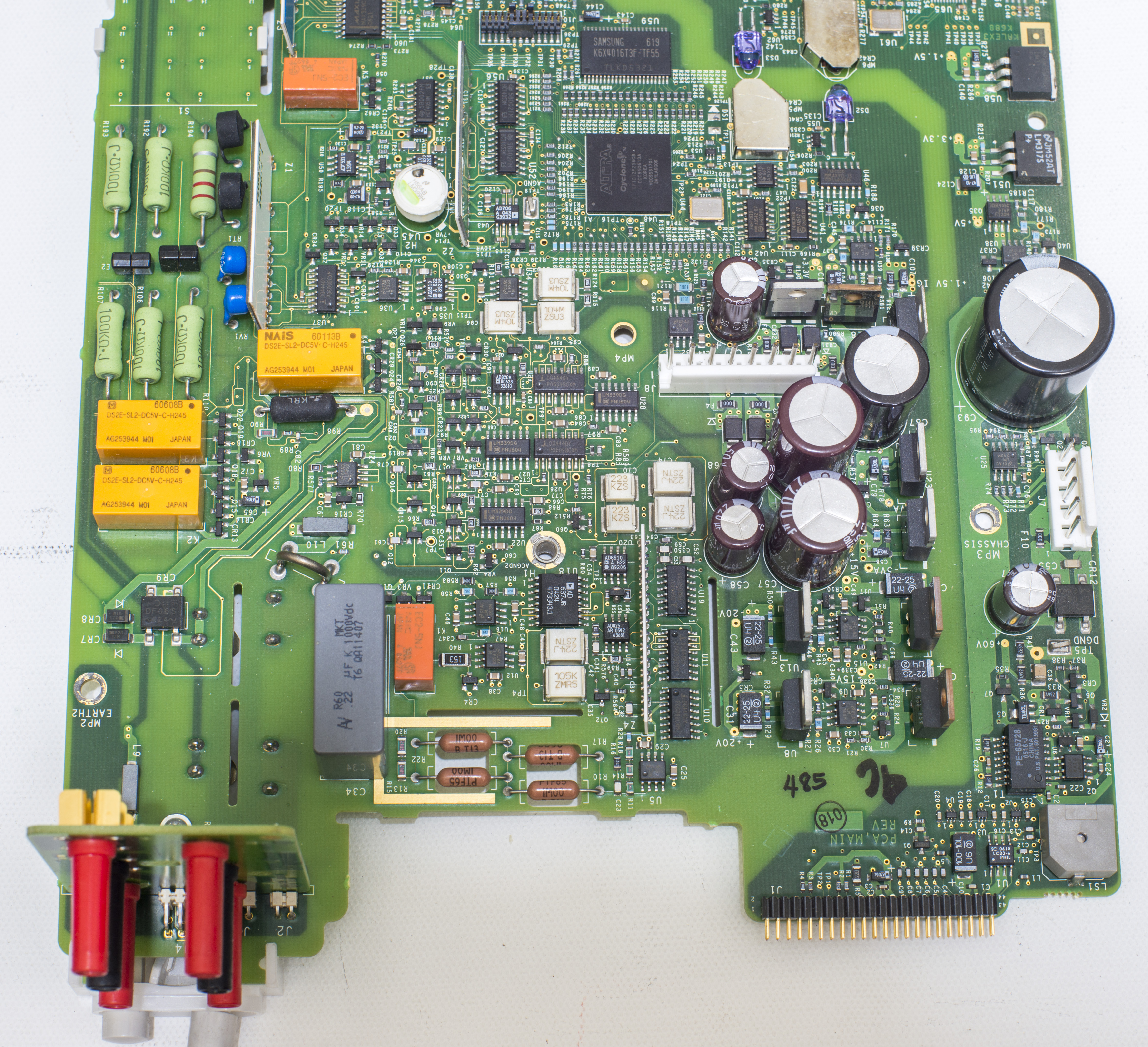
Image 14: Overview of the DMM’s mainboard, top component side
Nice tidy layout, with wide isolation gap between earth-referenced digital domain and isolated floating analog (in-guard) domain.
Input and rear banana terminals are mounted on daughter-boards, which are fixed on mainboard PCBA via right-angle 2.54mm spacing headers. Special patented split terminal jacks for the 2×4-wire ohms function also used for front HI/LO inputs.
This 2×4-wire connection allow you to perform true 4-wire measurements using special Fluke TL2×4W leads with dual isolated conductors instead bulky traditional 4-wire 4-probe leads. This is especially helpful for tiny SMT parts probing.

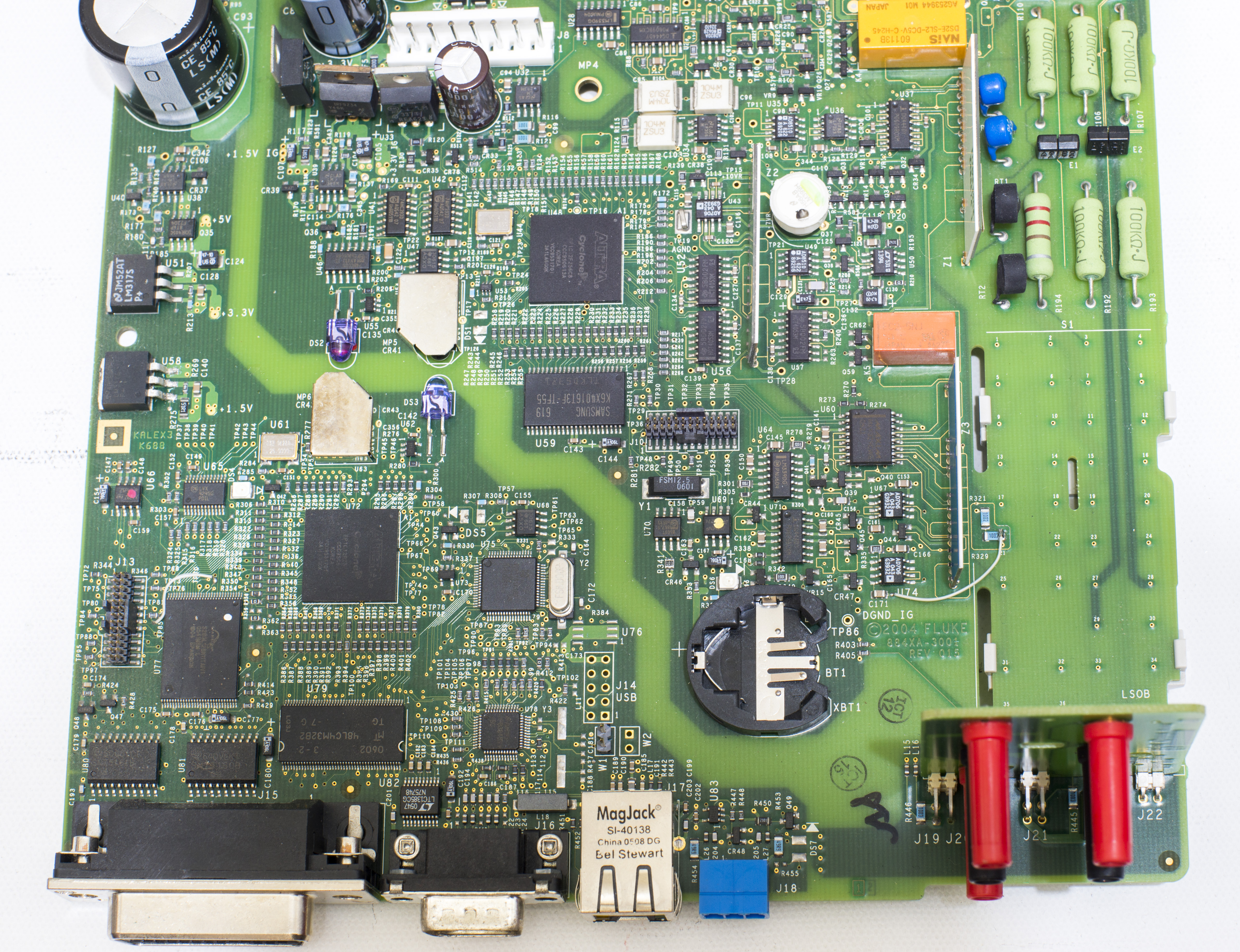
Image 15: Overview of the DMM’s mainboard, bottom solder side
Front/rear inputs switch is somewhat convoluted flimsy plastic assembly which just moves contact brush on bottom side of the PCB. As result there are two alternating buttons on front panel. And they are hard to press. I’d rather see more traditional multipole switch like used in many other meters, including old Fluke 8842A.
%(imgref)Image 16-17: %
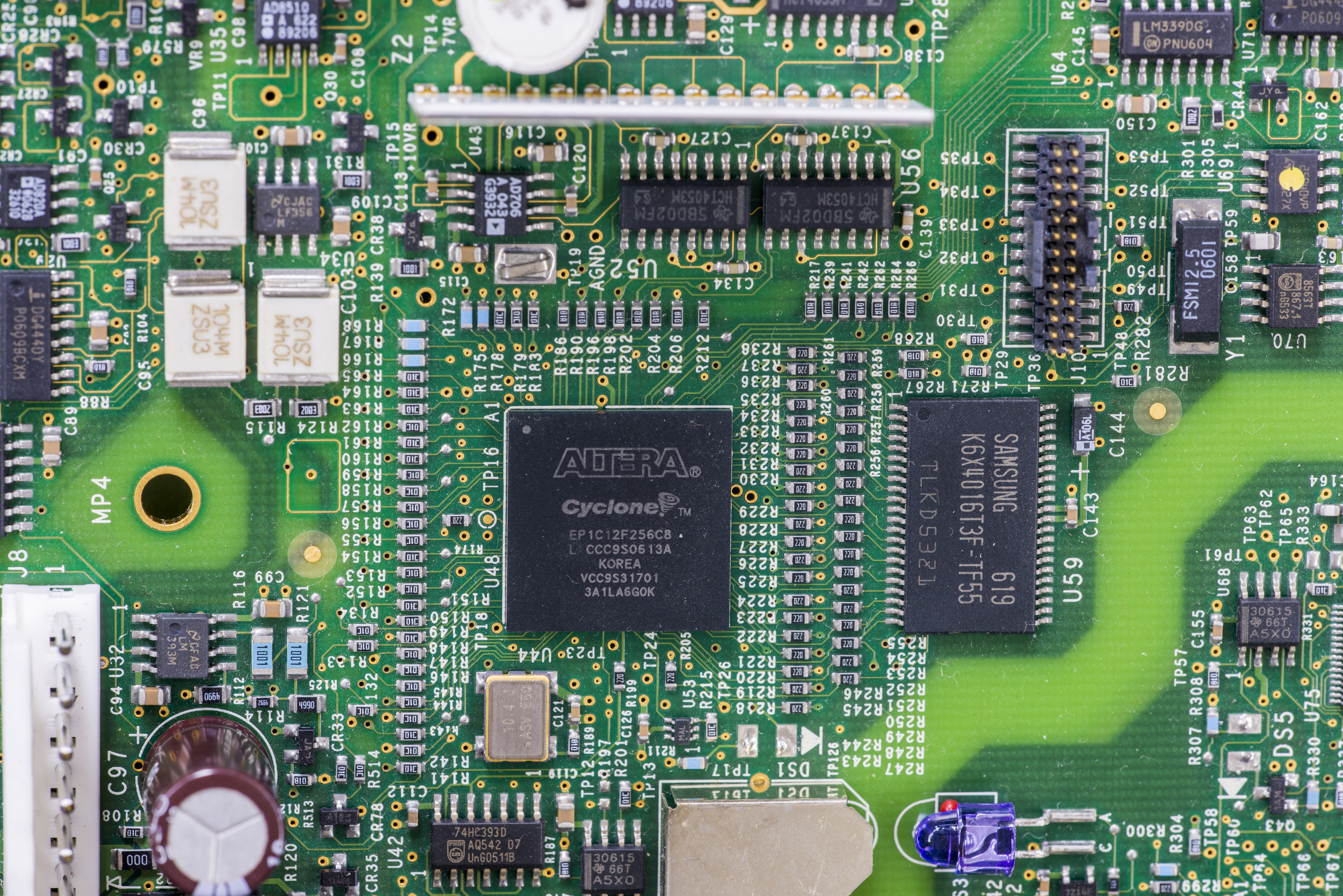

Image 18: Inguard and outguard ALTERA (now Intel) Cyclone 1C12 FPGAs.
Spansion S28GL128N11TAIV1 NOR flash next to outguard FPGA store linux OS and meter application. 128Mb SDRAM from Micron (MT48LC4M32B2) acts as system memory. Pair of SOIC-W packages next to GPIB connector are traditional 75161 and 75160 level translators. And yes, there was a dead spider on top of U81.
On the right side we have USB2.0 Host/Device controller ISP1161A1BD from Philips, little Texas Instruments TPS3306-15D supervisor IC and DP83848 10/100Mbps Ethernet PHY. Linear LTC1385CG is just a level translator for RS-232 port, similar to ubiquitous Maxim MAX3232’s.
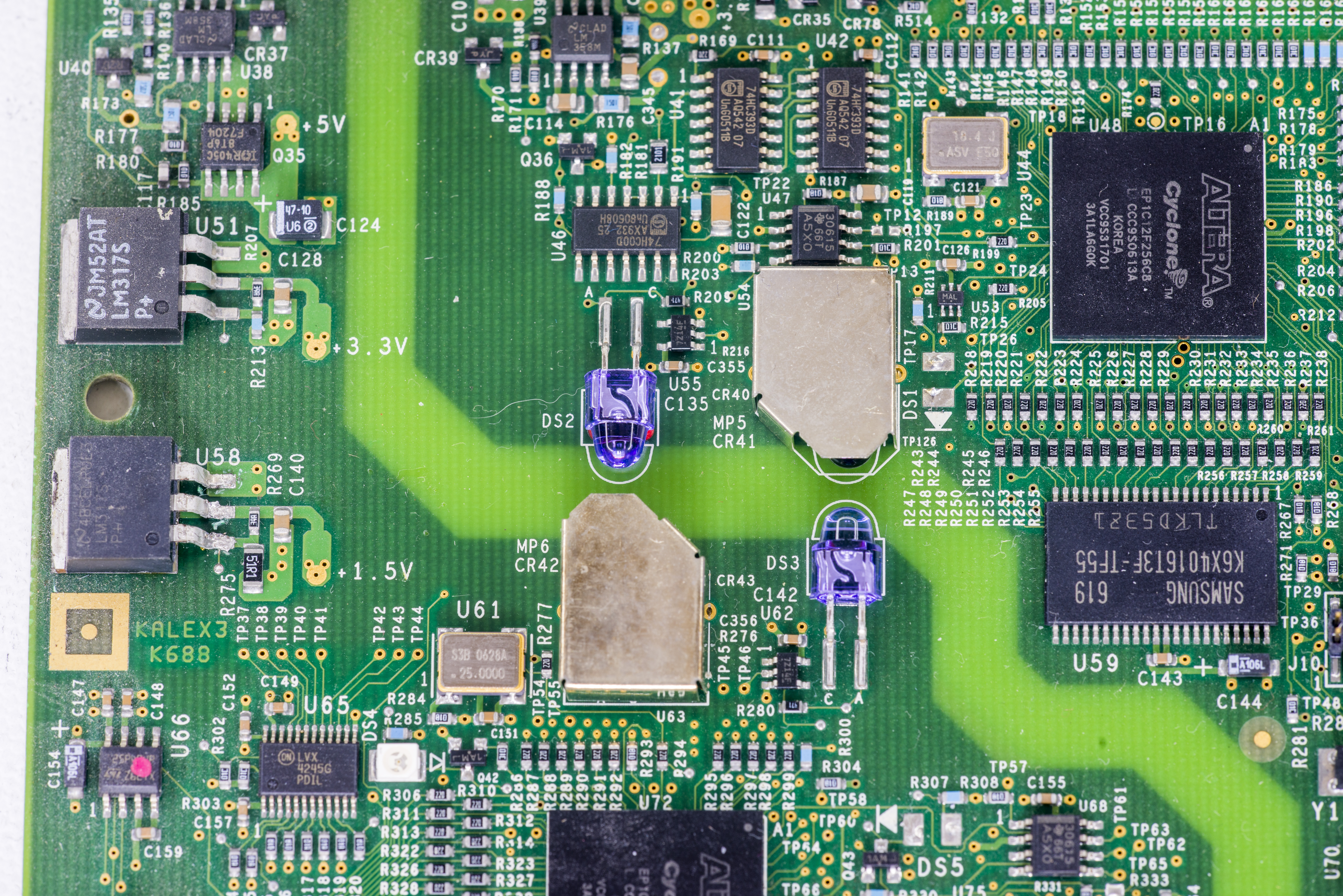
Image 19: Infrared discrete diode and phototransistor pairs.
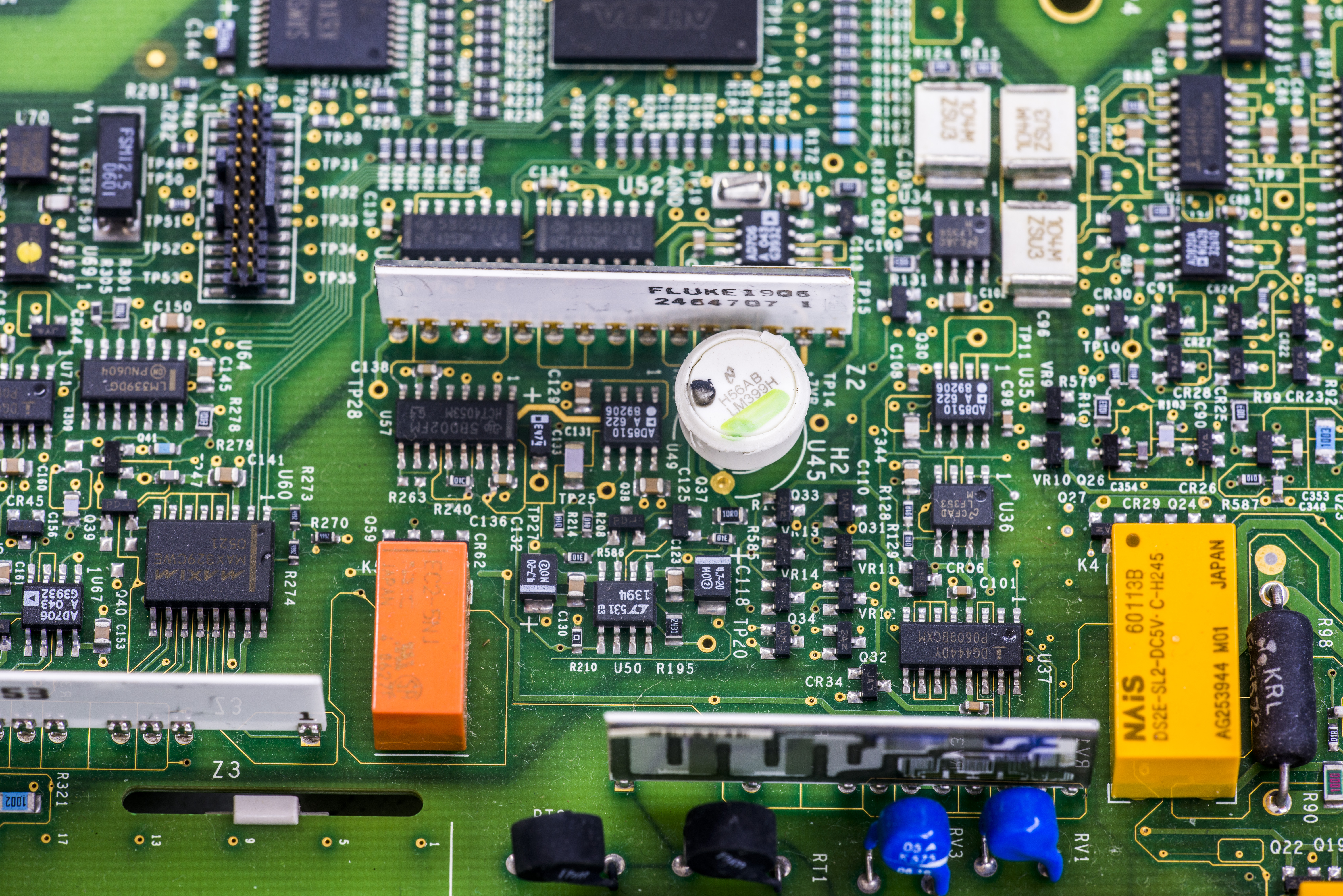
Image 20: Voltage reference LM399 and precision resistor networks
Main voltage reference surrounded by ADI operational amplifiers, is well known Linear (now Analog Devices) LM399H, soldered on tall legs, protected by plastic standoff from air drafts.
Precision laser-trimmer resistor network next to it used to generate various reference levels out of stable 6.95V voltage from LM399H output. As we have extra resistor network from this very meter model, it was possible to measure and reverse engineer schematics of this resistance network.
AD706 used here is picoampere bias low-noise opamp, in dual configuration, and AD8510 is a single JFET opamp with low noise, 8 nV/√Hz at 1 kHz. Ofcourse here we have also various analog switching components to select desired signal paths, most using 405X-series devices and small SOT23-3 JFETs.
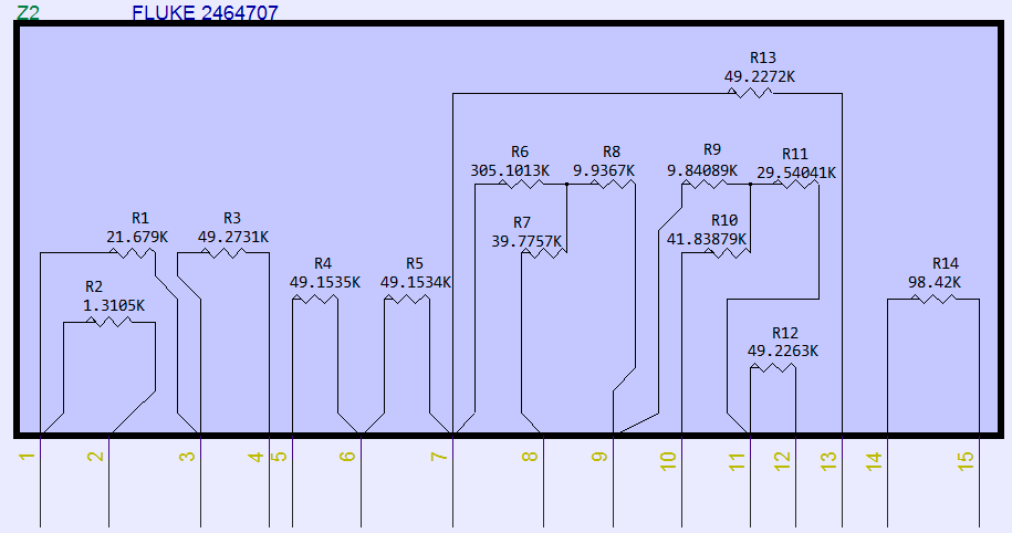
Image 21: Fluke P/N 2464707 resistor schematics
Such network can be very handy to build precise 7V to 10V amplifier for LM399 or LTZ1000A based reference. Few example schematics covered in this detailed article about these hermetic networks.
In fact this resistor network is one of the key performance enabler in our own Model FX 10.00000V LTZ1000A-based reference. In ratio circuit like 7V to 10V amplifier, absolute temperature stability of each resistor element is less important than matching. As result resistor networks like this Fluke 2464707 with tight element matching is the best option to provide stable output voltage boost for the reference.
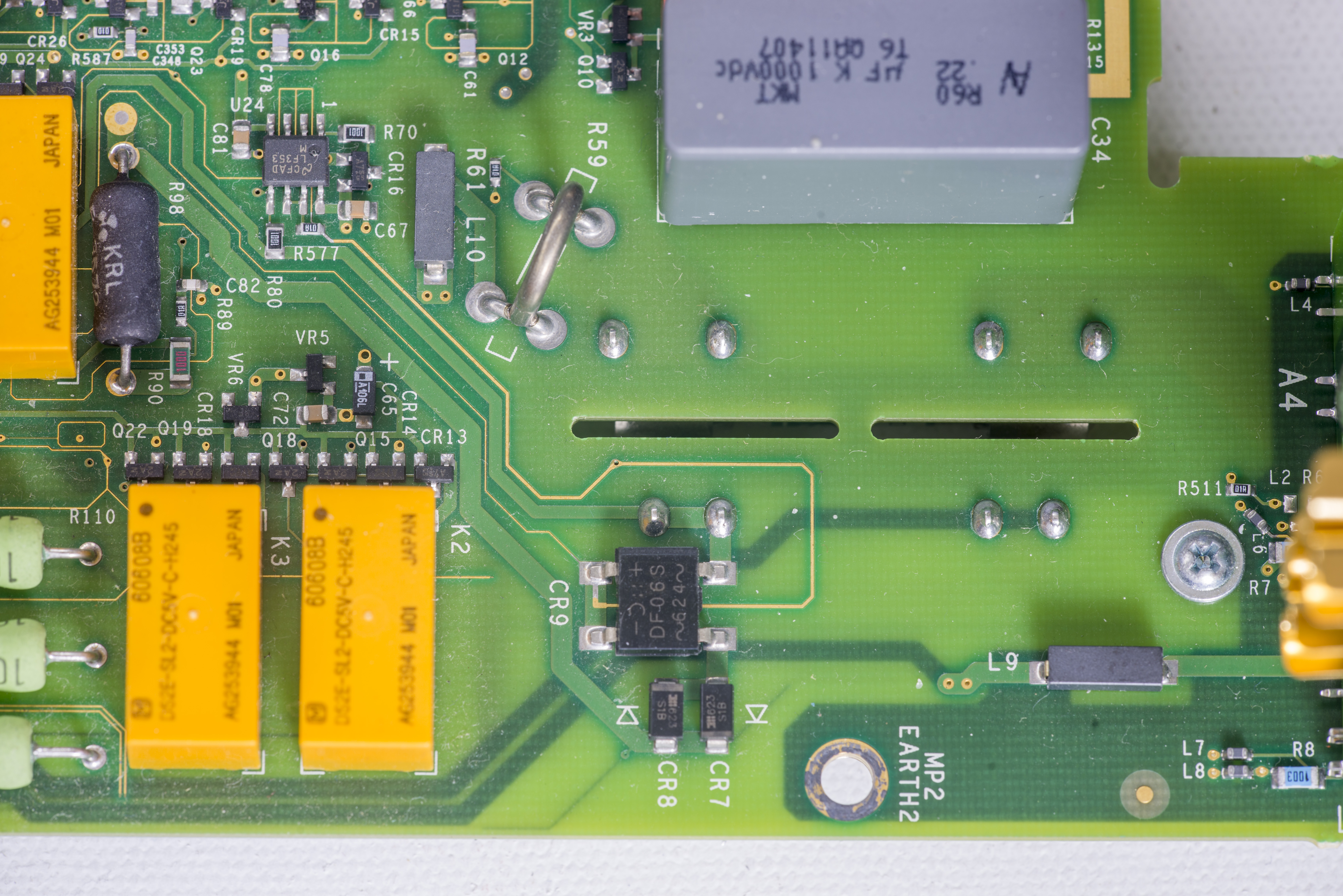

Image 22-23: .

Image 24: .
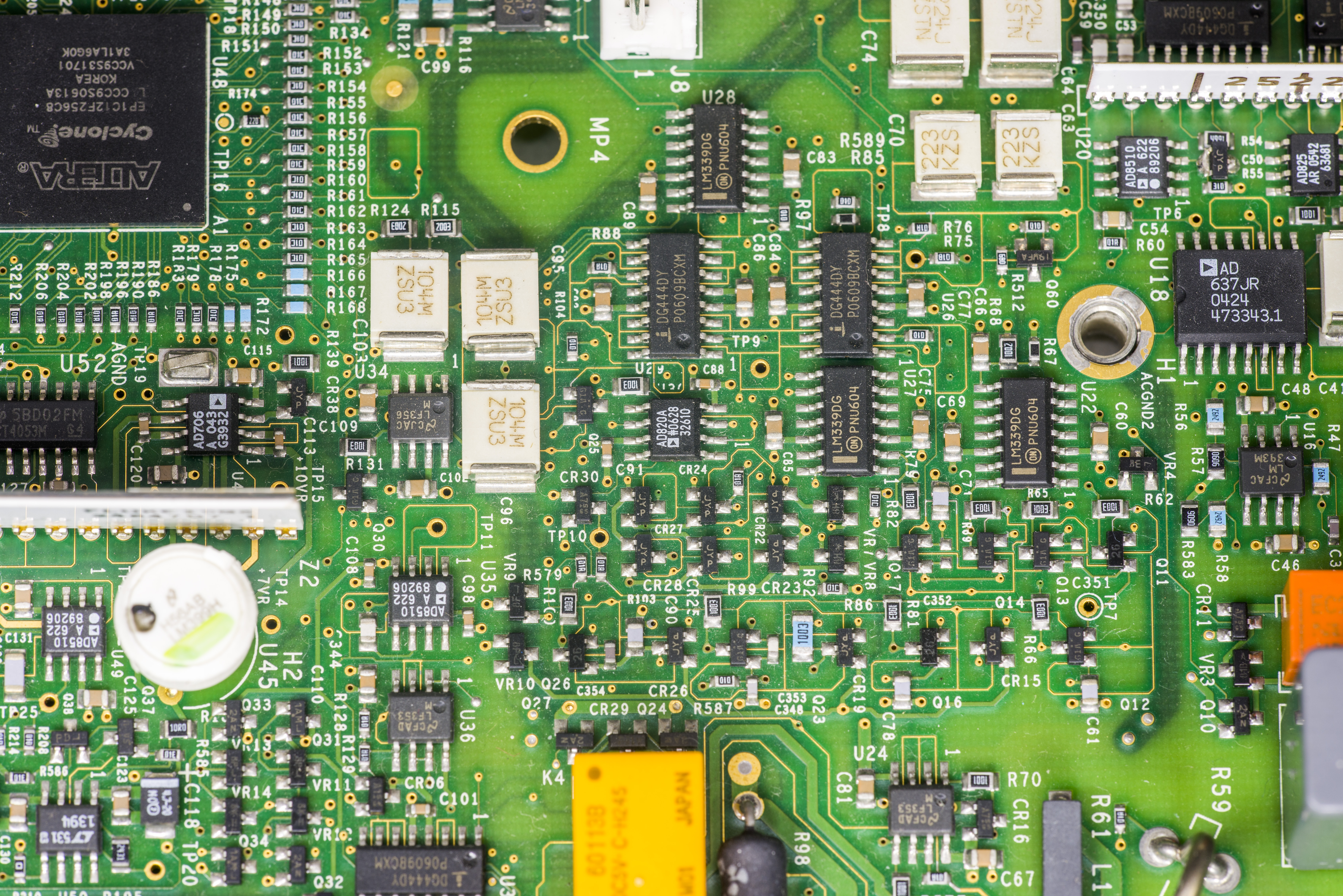
Image 25: .
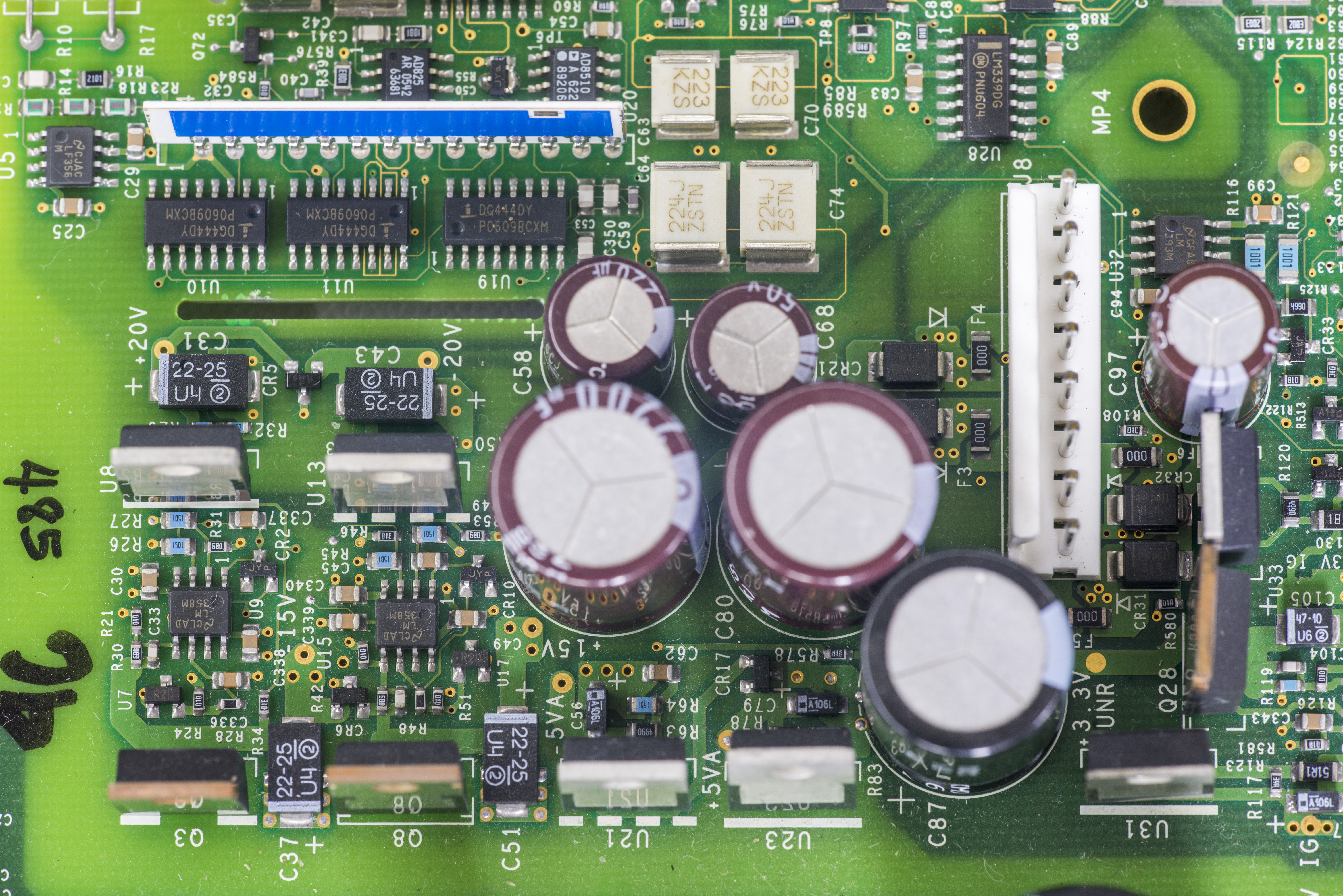
Image 26: .
Story of the missing CR56 shottky diode?
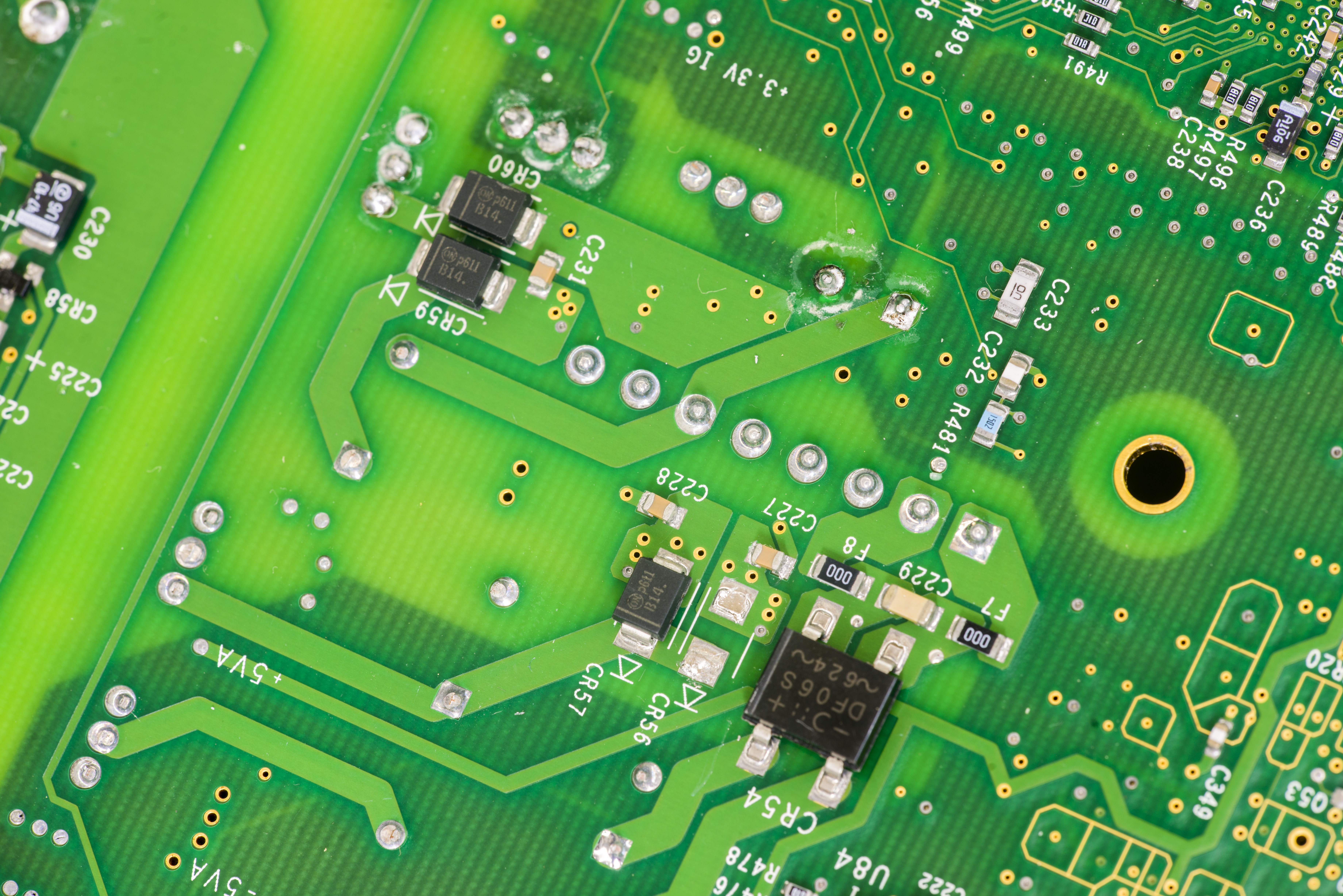
Image 27: .
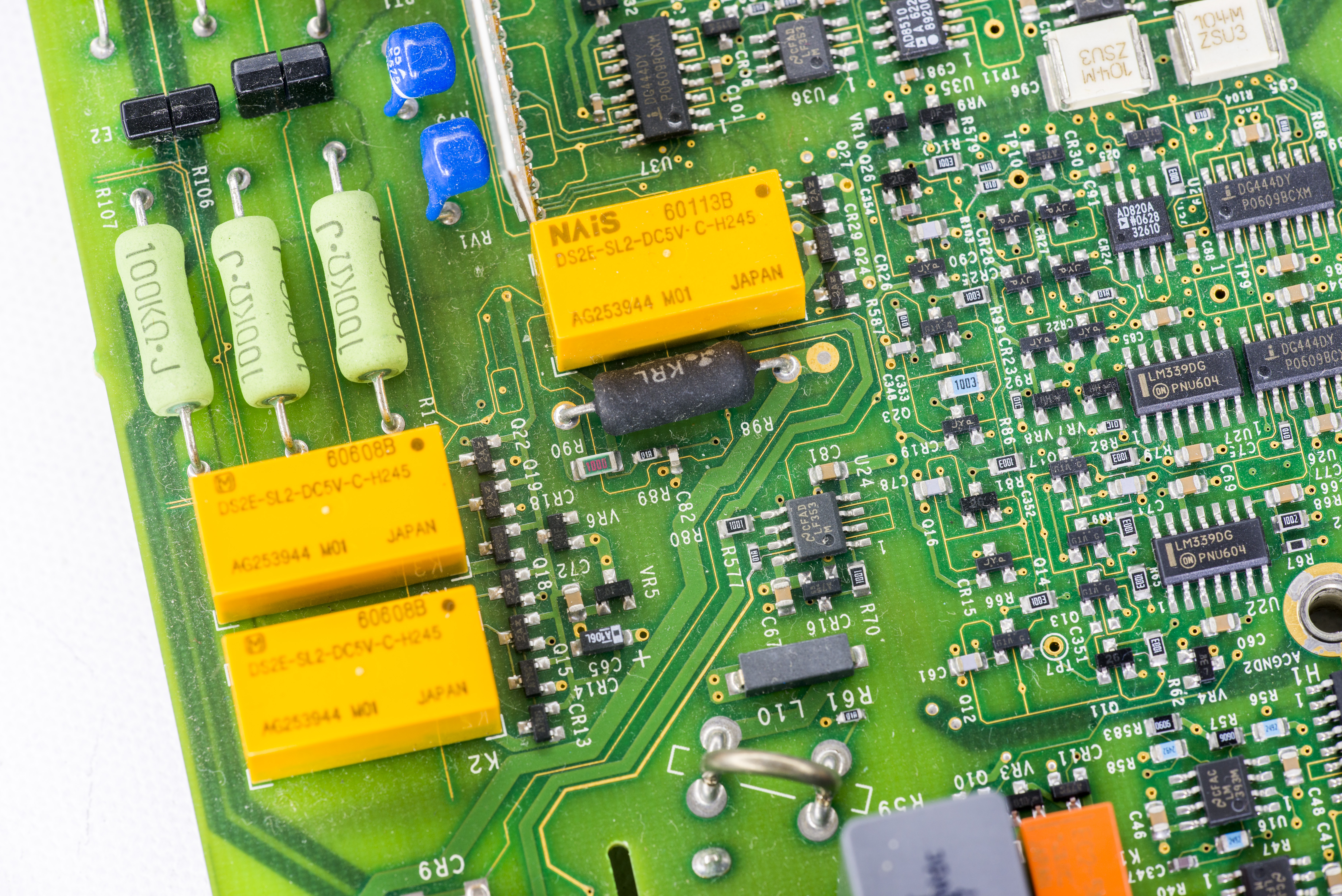
Image 28: .
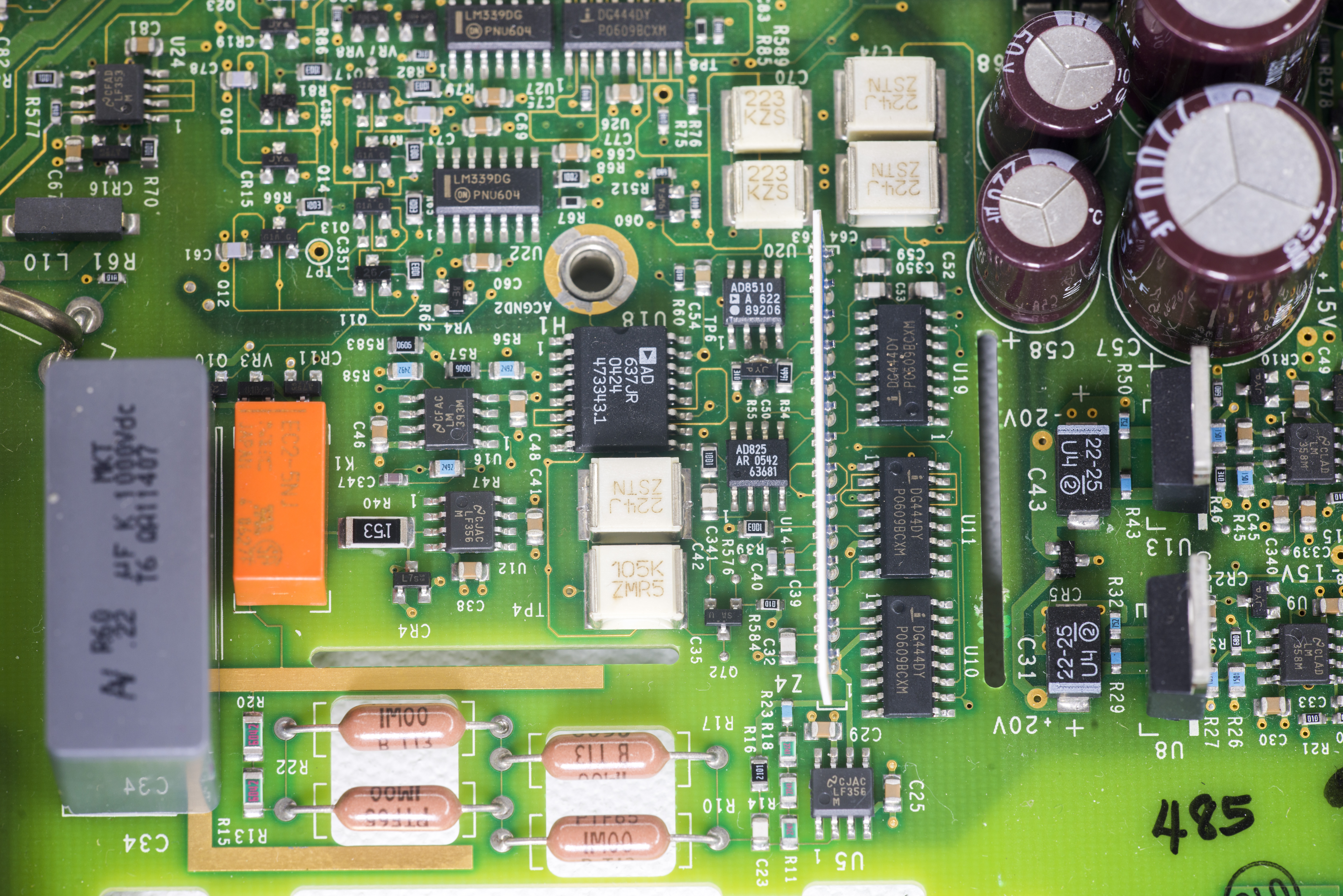
Image 29: .

Image 30: .
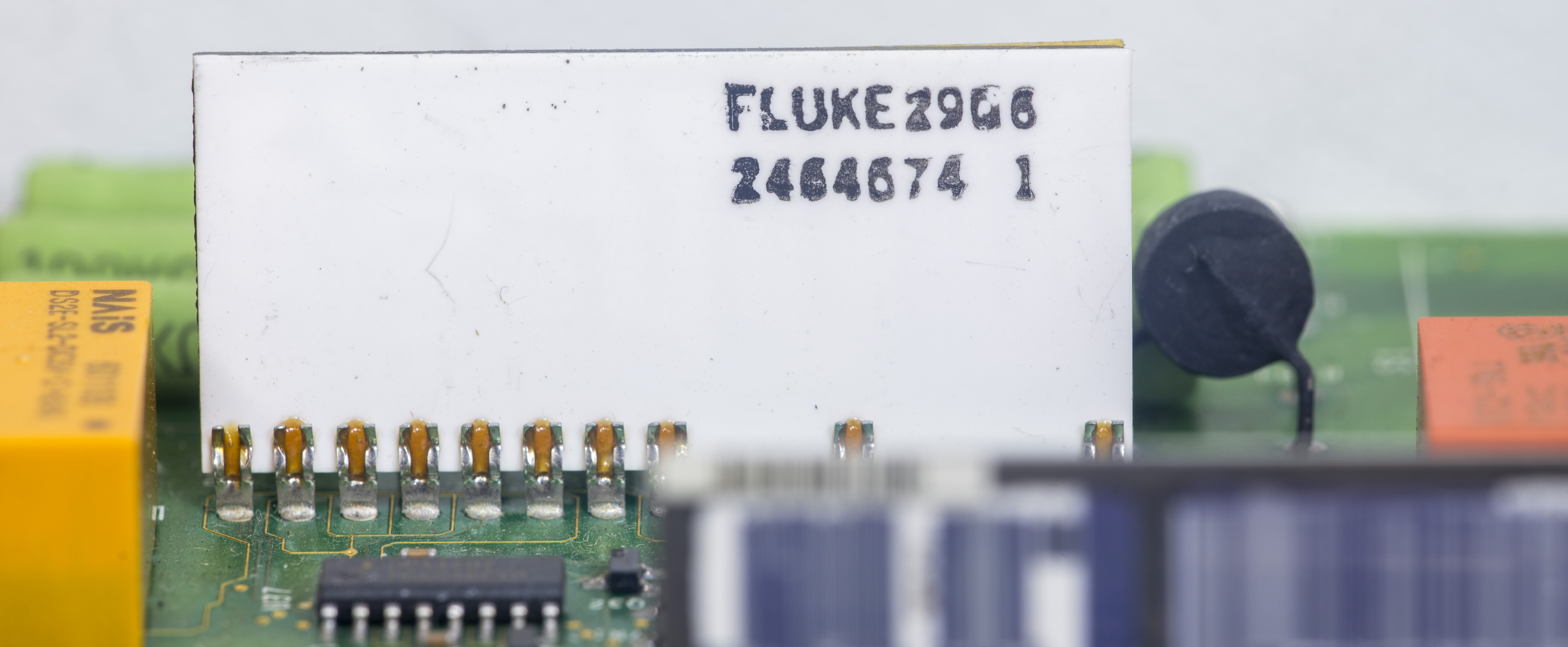
Image 31: Fluke network P/N 2464674 for high-voltage divider
Fluke’s resistor network shown on Image 30 is used to divide high-voltage input voltage to acceptable ADC input levels and to provide precision scaling for some other functions of the meter. High-value 10 MΩ resistor clearly visible by large area of thin serpentine resistive material trace.
Since there is no public schematics for Fluke 8846A DMM, we can only guess from the common sense of typical front-end analog design, used in other similar meters, so this design is typical in many benchtop meters.
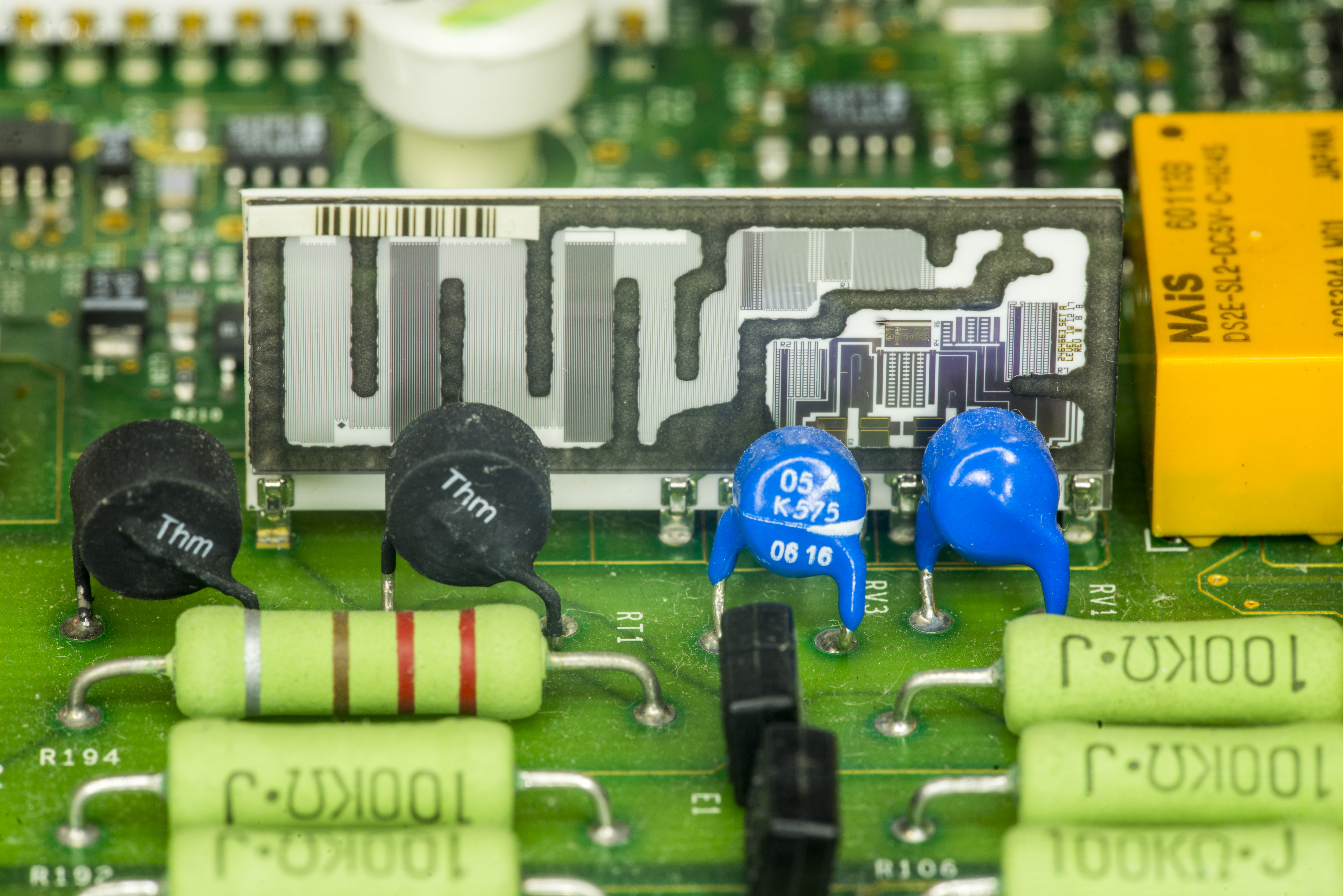
Image 32: .
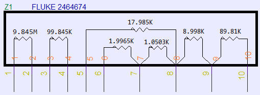
Image 33: Fluke P/N 2464674 resistor schematics

Image 34: .

Image 35: Cute SOT23-3 bodge on top of 0805 MLCC capacitor
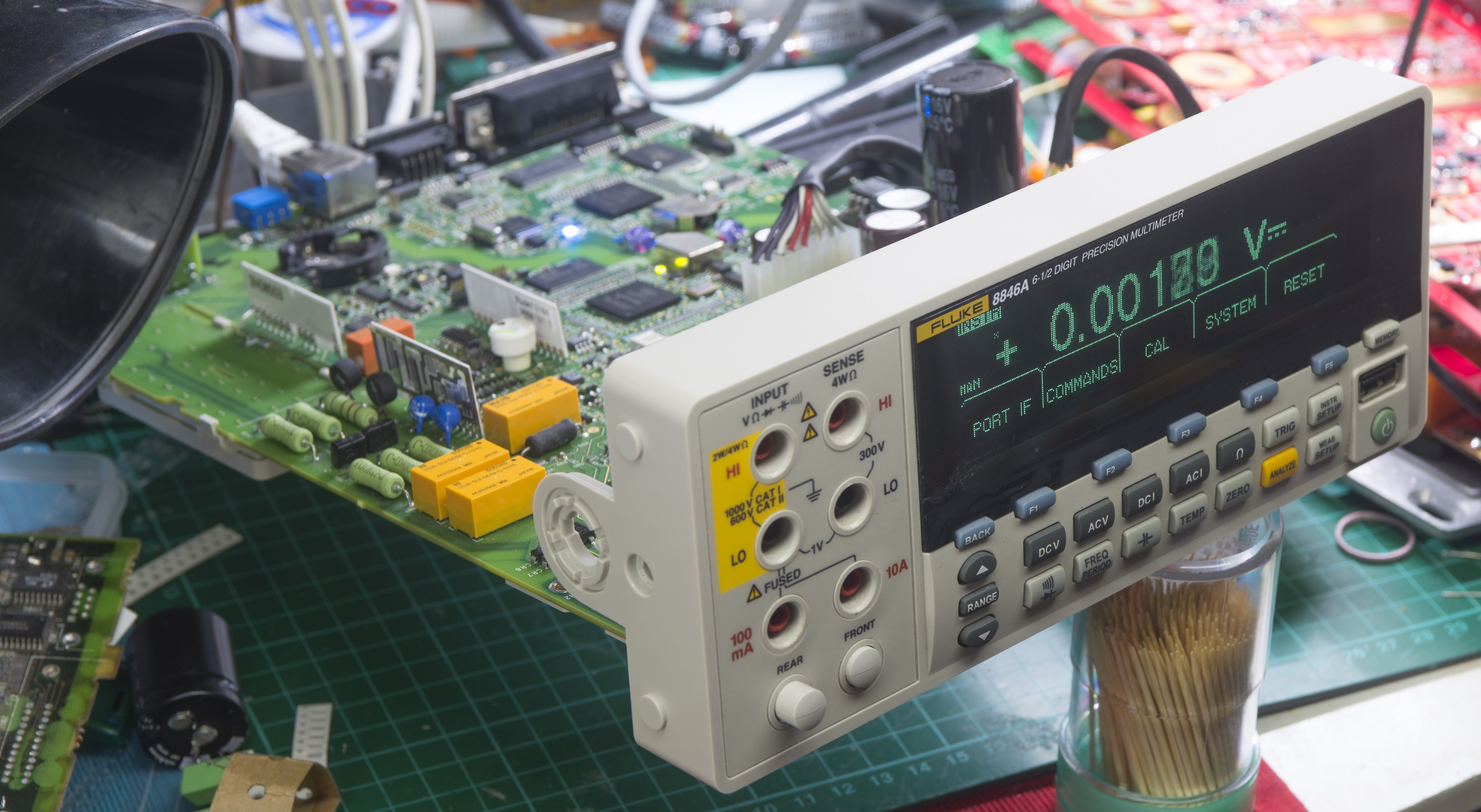
Image 36: It’s alive! Well, for now..

Image 37: .
DC Voltage tests
After initial steps in troubleshooting, and poking around with freeze spray around optoisolation barrier parts meter suddenly came back to life. It worked for about an hour, which was promising enough, that it got connected to our Fluke 5720A to perform some quick checks.
This DMM, just like any other complex electronic measurement equipment service cannot be completed without proper verification of measurement accuracy and calibration. So to do required performance tests, three stages will be done, an acceptance test after repair. Calibration manual recommend to use 90-day specifications for performance test after calibration, but we can restrict conditions to even worse condition, and test against 24-hour specificaitons. This is possible because no shipping or other major disturbances are involved, as meter calibrated and tested on the same station. Properly working meter must be able to pass all 24-hour specifications with good margin, to provide confidence of the test result data.
Because of wide range of functions 8846A require set of high-performance reference sources or multifunction calibrator to do full test. Calibration manual calls for Fluke 5520A calibrator, Fluke 8508A reference DMM to test that calibrator and low-thermal 4-wire short. However we will use different set, utilizing what is available in lab:
- Fluke 5720A for DCV, ACV, DCI, ACI and Resistance tests
- Keysight 3458A and Fluke 8508A as reference meters
- Set of DIY capacitor references, measured by HP 4263B LCR
- xDevs.com 1GΩ resistance standard box
- 4-wire short PCB
- Time Electornics 9823 calibrator for 10 A range
- HP 33120A ARB generator, locked to TEMEX Rubidium 10MHz frequency standard (calibrated to Trimble GPSDO)
- Agilent E5810A GPIB-LAN interface gateway with Raspberry Pi 3, running python code for control and automation
Calibrator was adjusted to reference standards just a week ago, and even annual specifications of 5720A are far more accurate than even 24 hour specifications of Fluke 8846A. 5720A output connected to 8846A using PTFE shielded 4-wire cables, with gold-plated banana posts on meter end, and low-thermal copper spade lugs on calibrator side. Ambient temperature was kept at +24 °C ±1 °C.
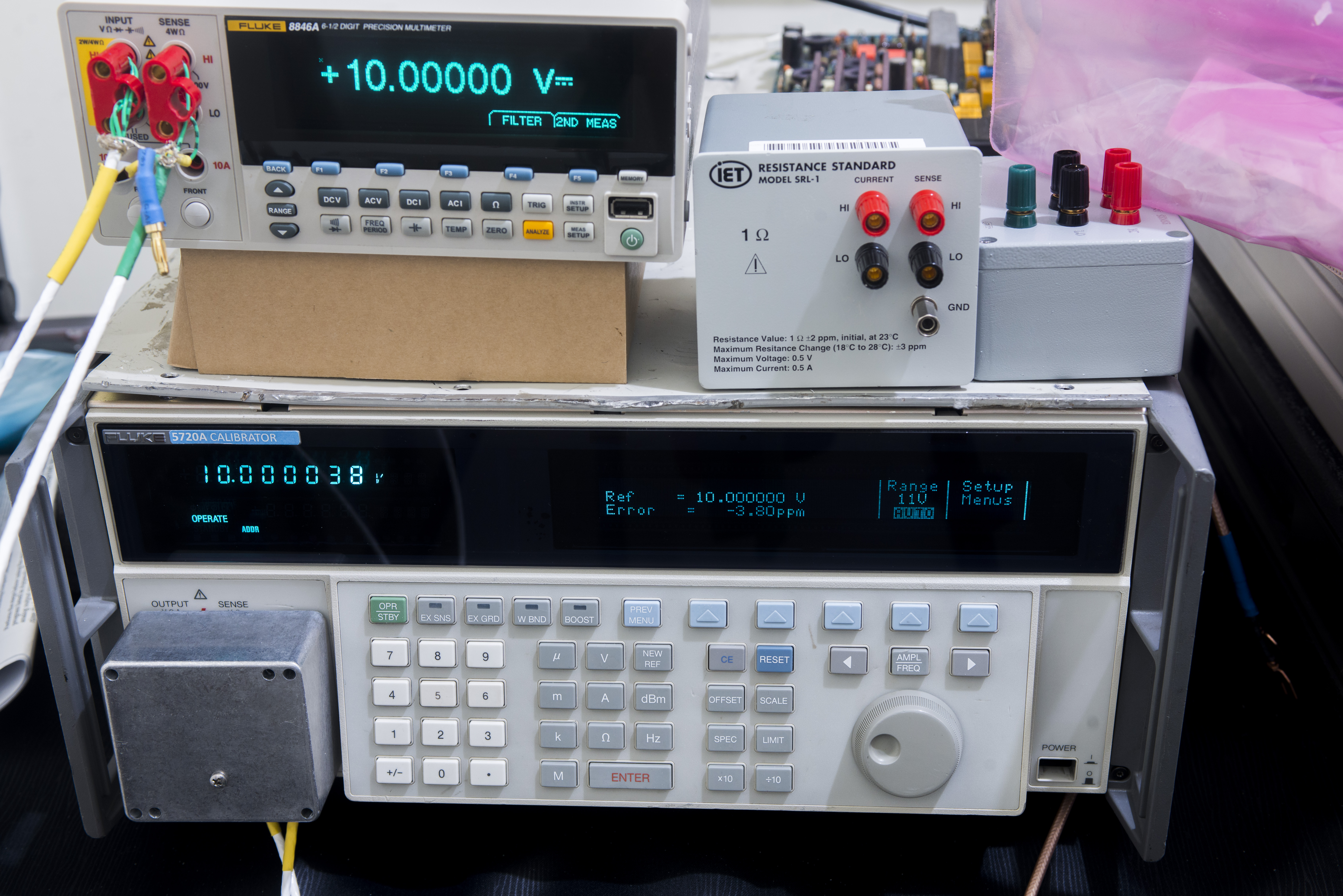
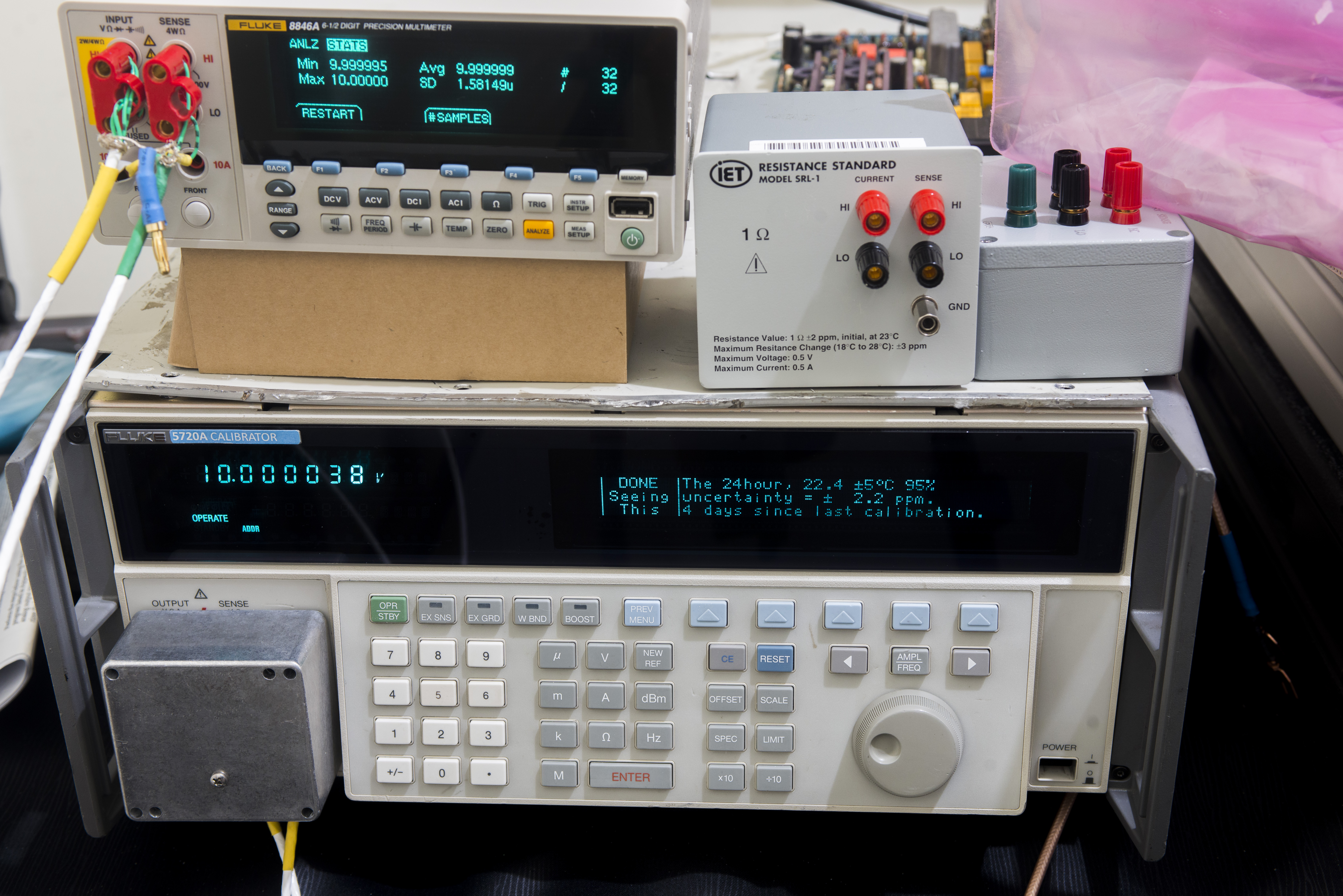
Image 38-39: DC voltage verification
There was no warm up time, essentially these are readings 10 minutes since power on. Not too bad at all, I was expecting far worse from 6½-digit multimeter, that is not targeted for any serious metrology work.
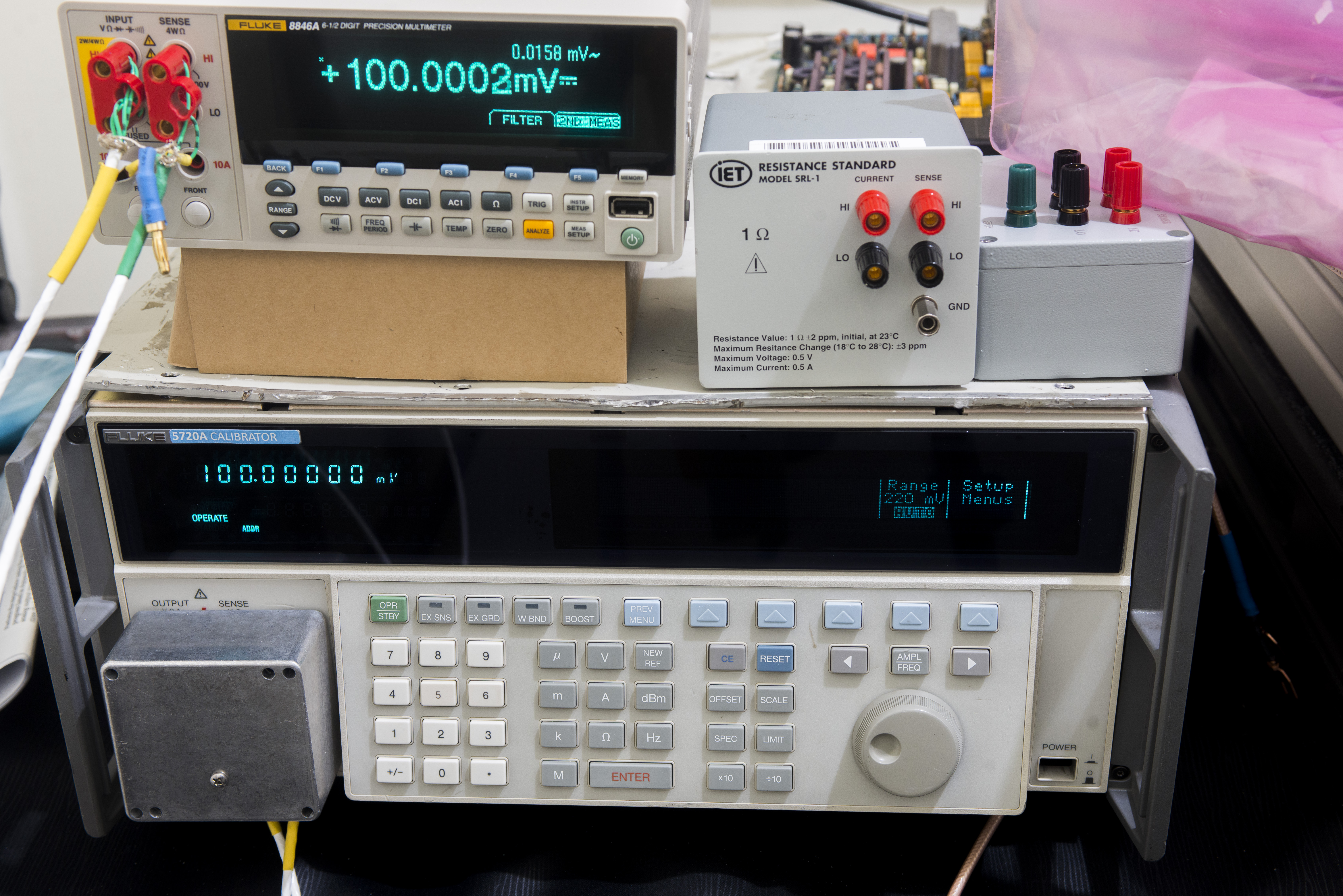
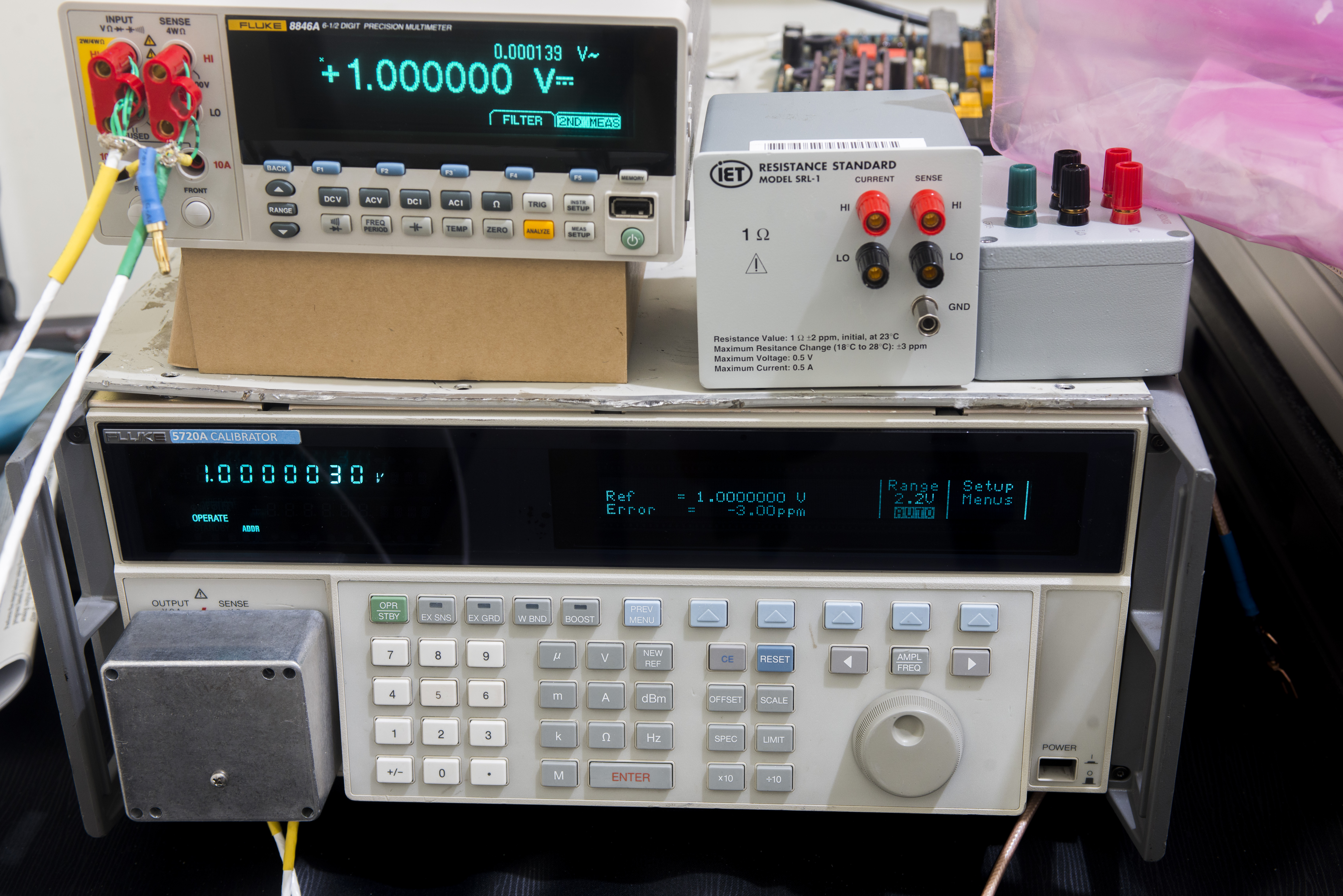
Image 40-41: .
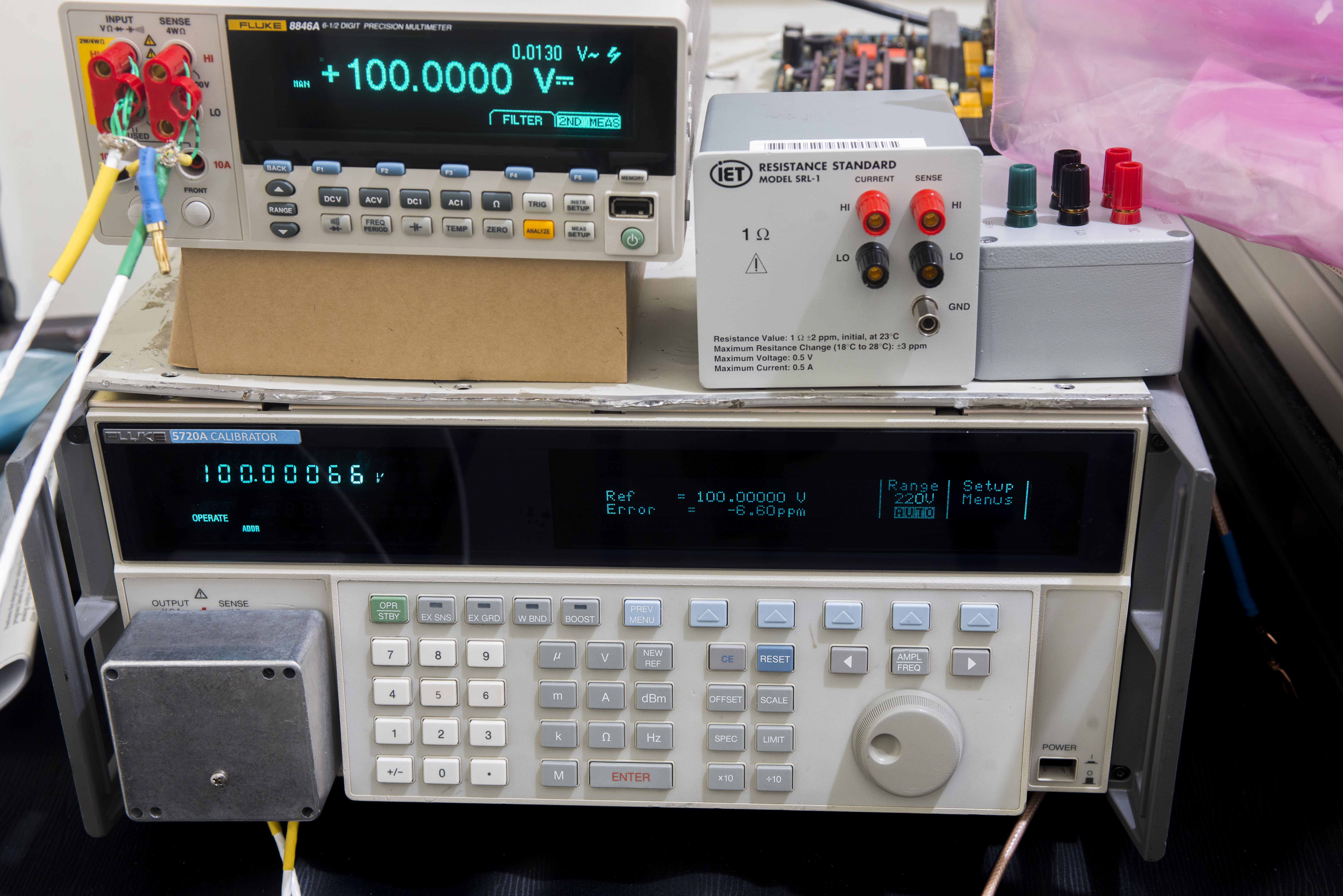

Image 42-43: .
Resistance tests
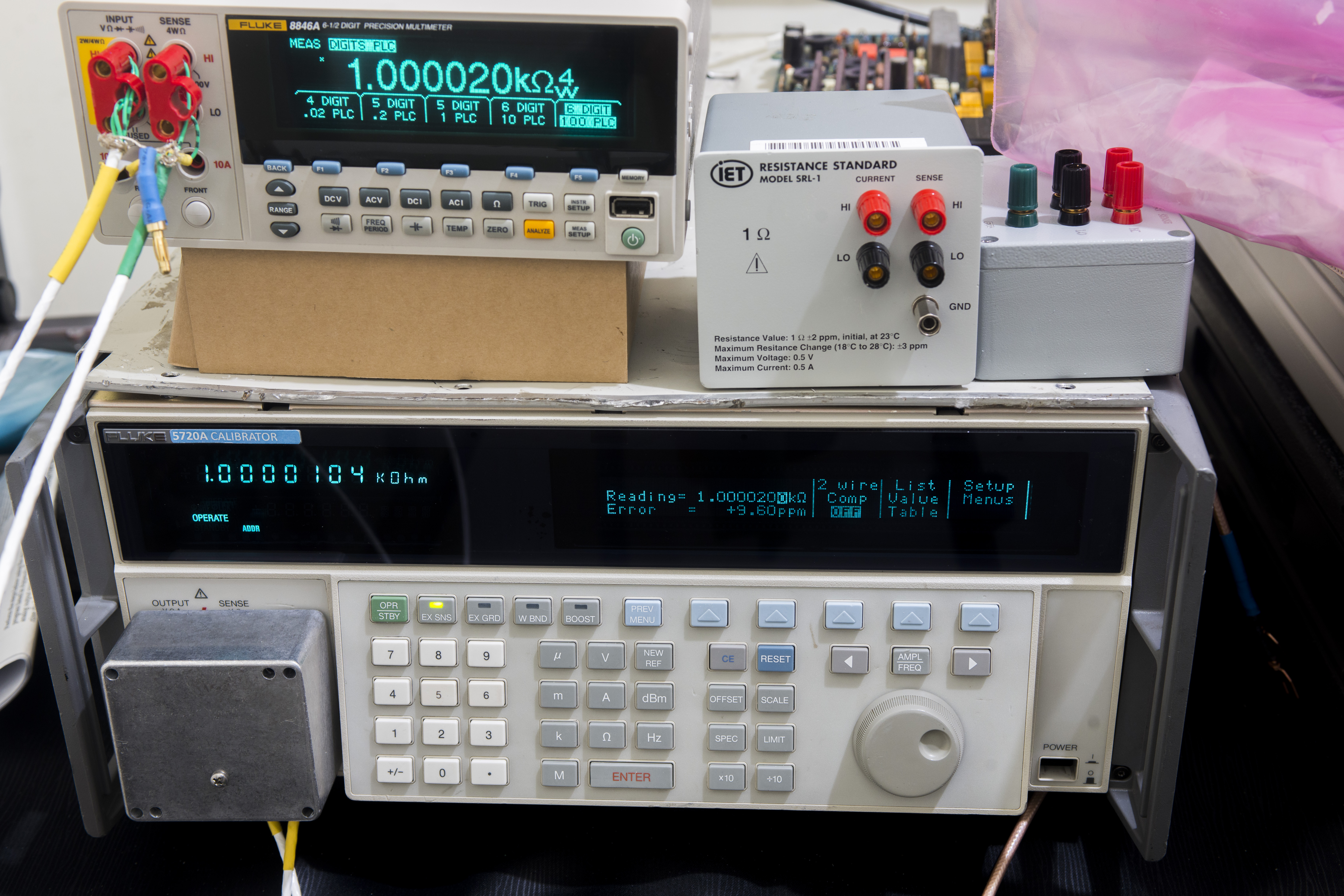

Image 44-45: .
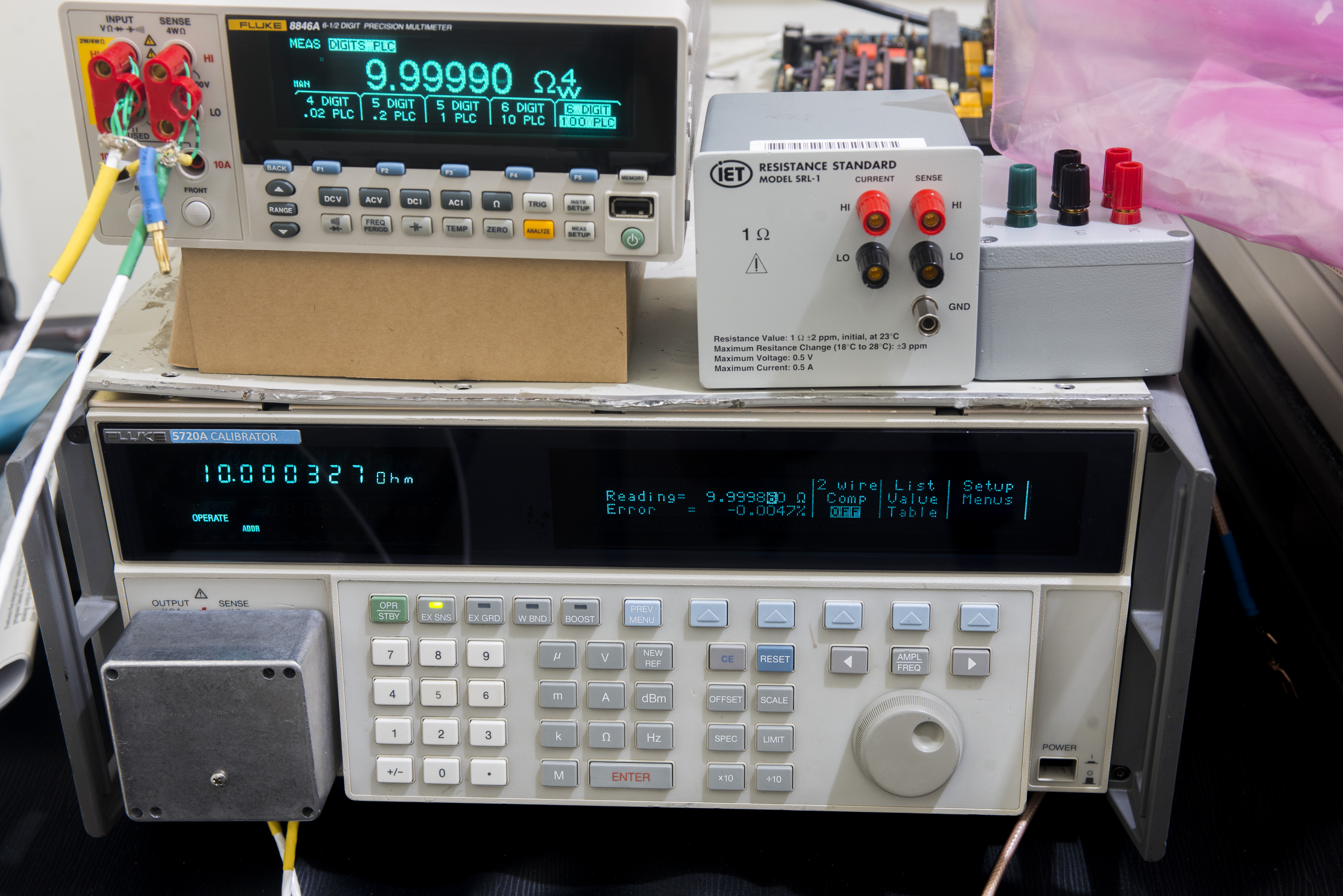
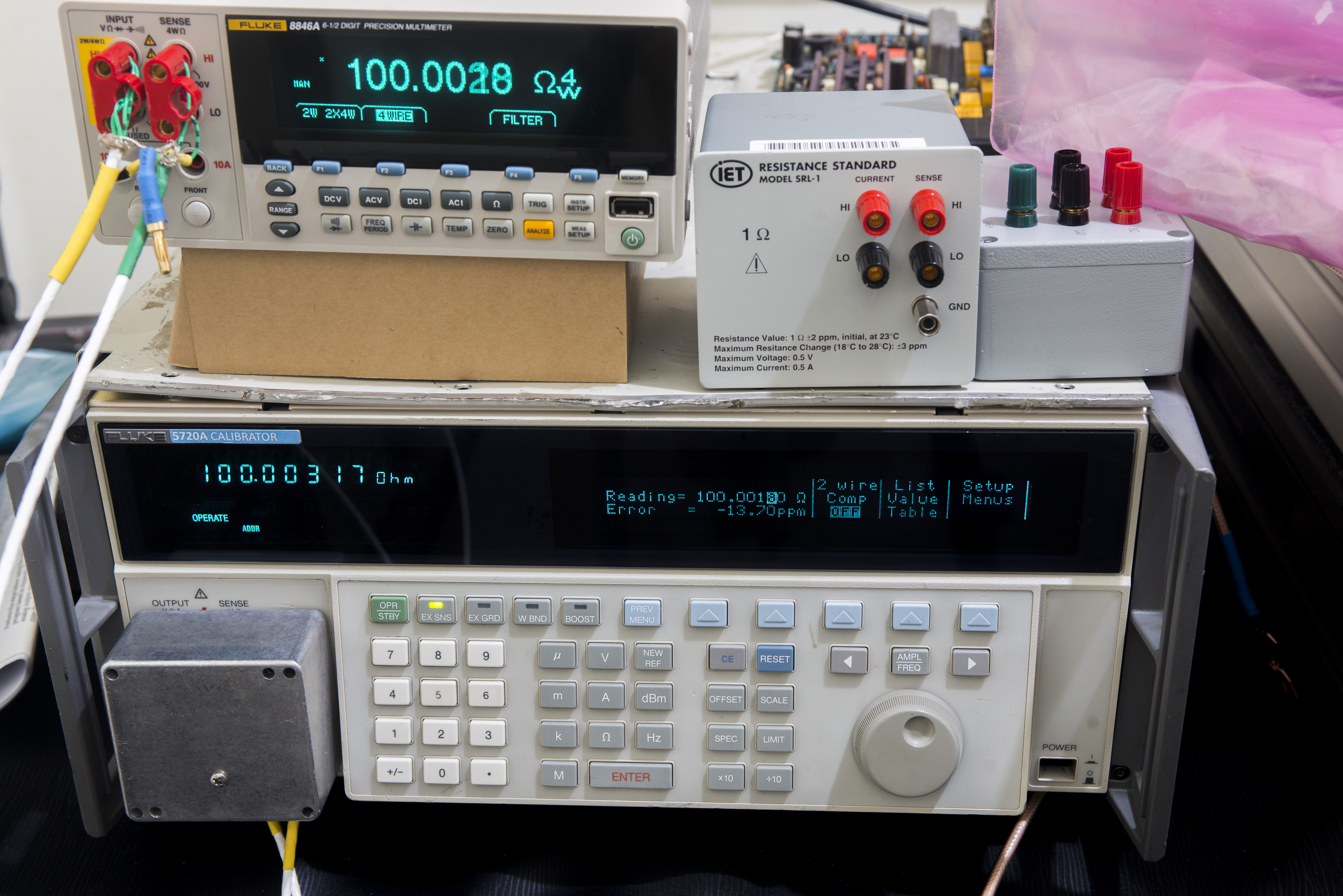
Image 46-47: .
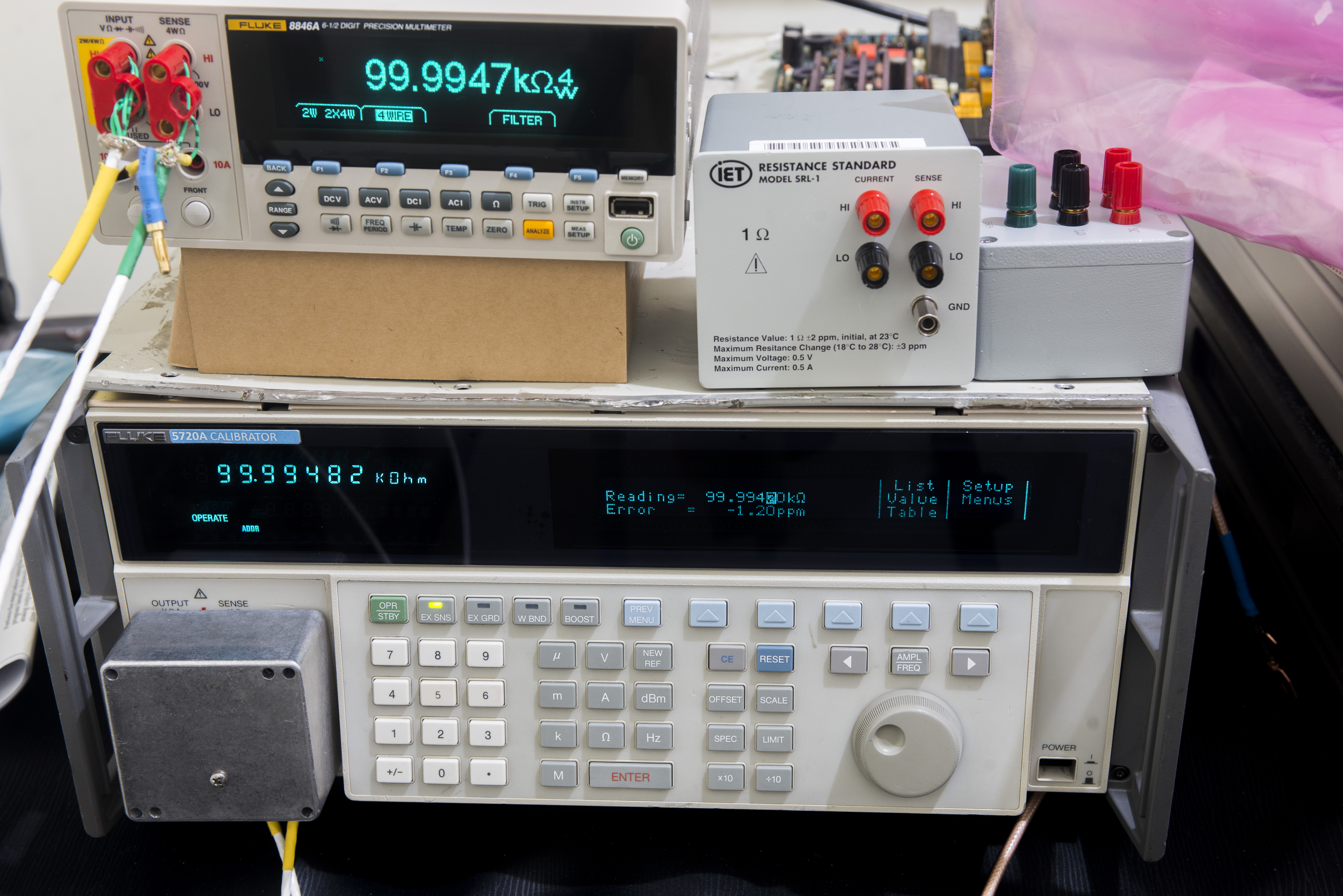
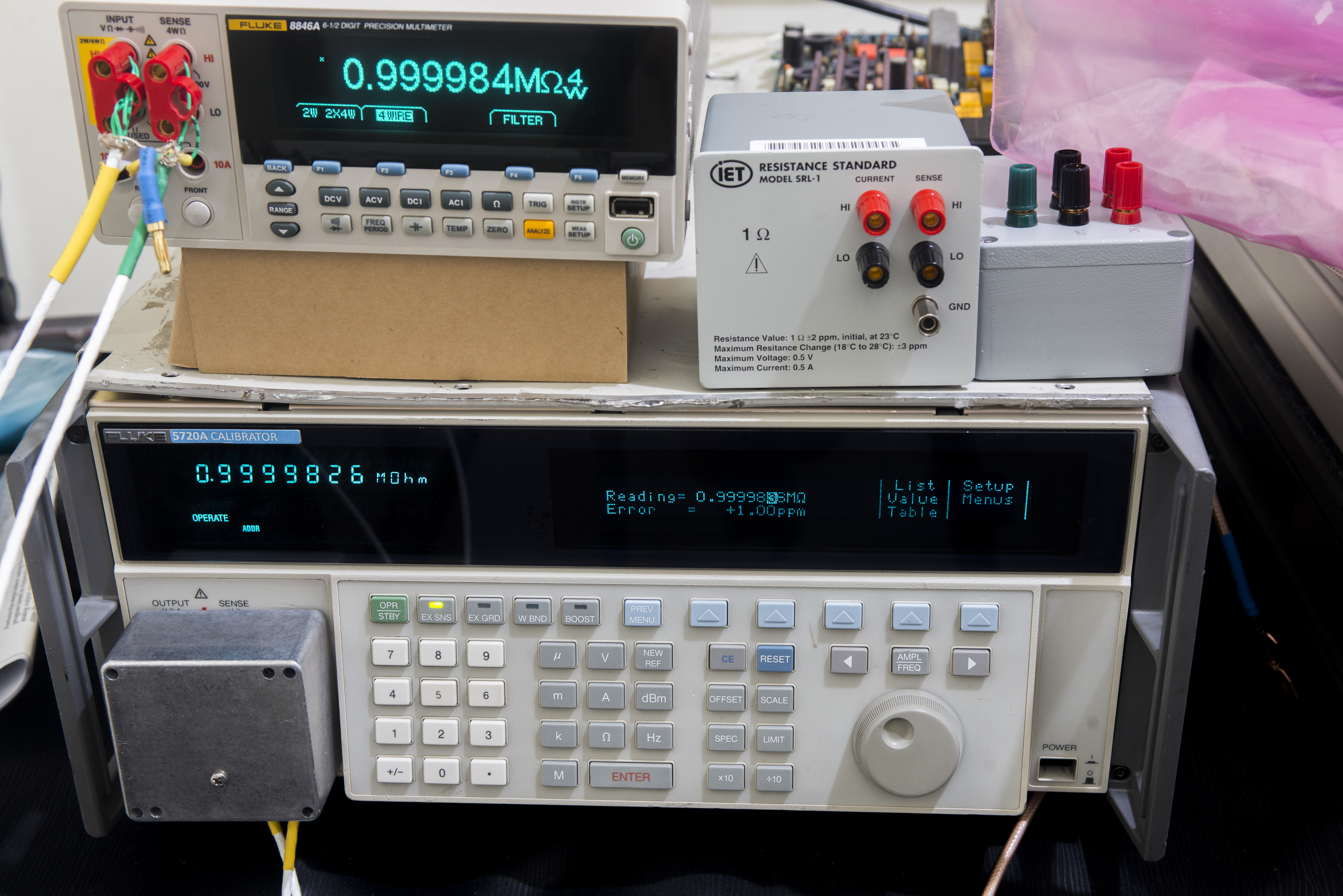
Image 48-49: .
Other functions test

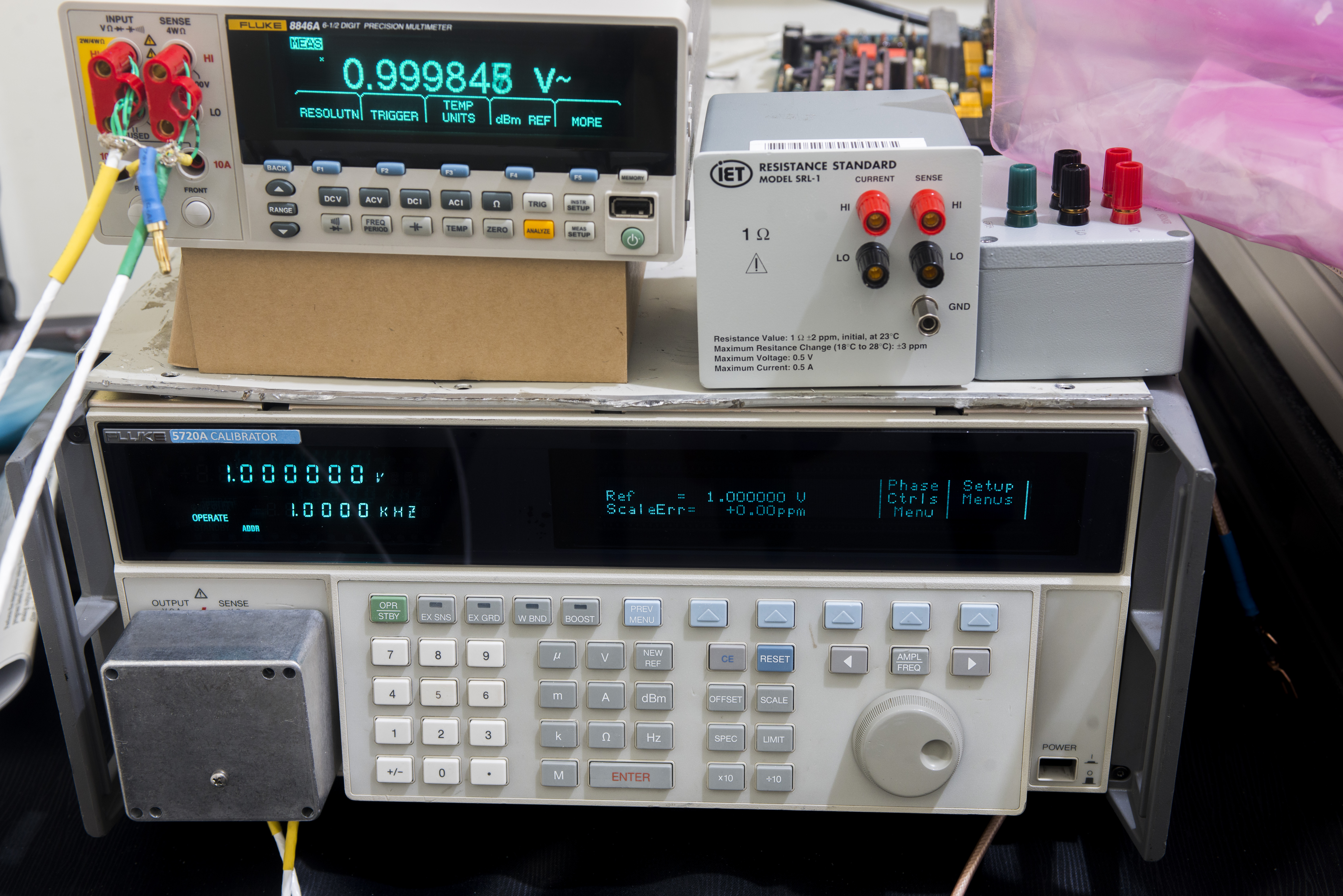
Image 50-51: .
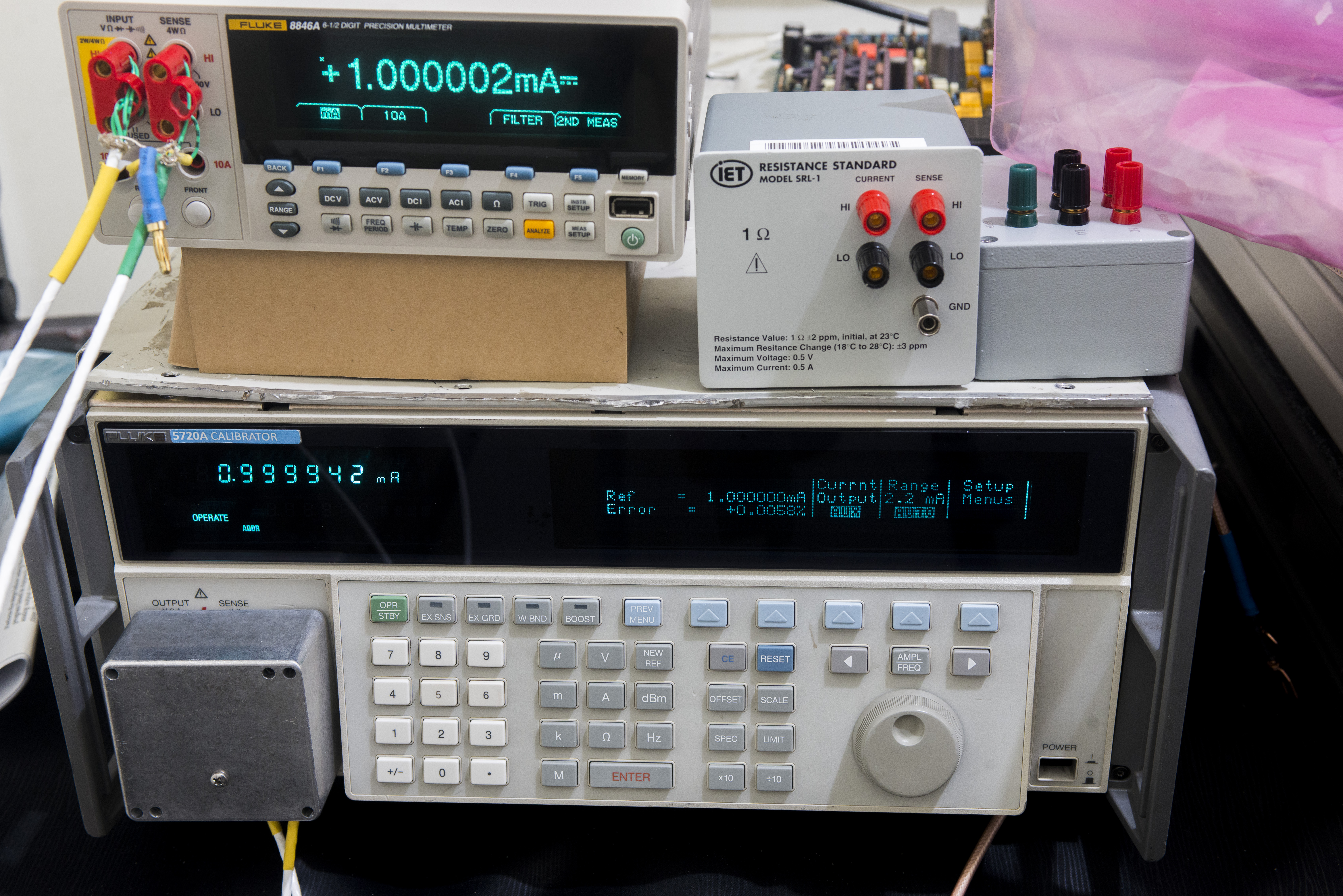
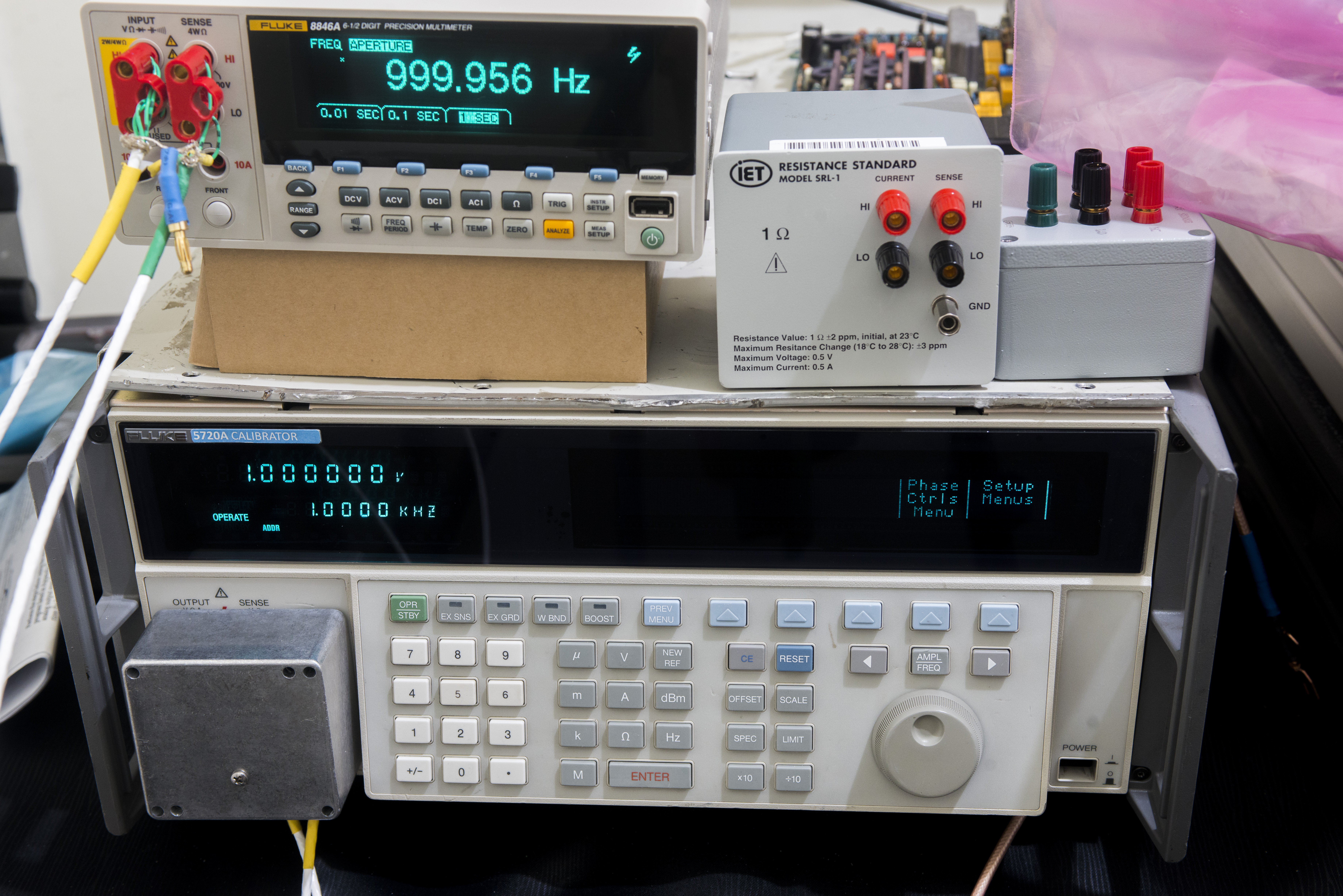
Image 52-53: .
But after running for 30 minutes or so, meter broke again, with same symptoms, hang on boot screen without any actions.
Well, apparently this repair project to be continued.
Sadly this Fluke 8846A after running for few hours stopped working again, hanging in the same boot-up sequence, displaying only the intro logo. Further attempts to bring it back, power supply troubleshooting and even FPGA replacement (hoping for bad BGA contact under chip) – did not help in any way. So this meter goes back to shelf, waiting for some better days with label BROKEN, FAIL TO BOOT.
Overall repair experience with Fluke 8845/8846A series is very bad, as they are filled with BGA parts, complex firmware and nearly zero of useful troubleshooting information, leave alone schematics or ability to easy backup/restore instrument’s firmware. Together with high cost, this makes it bad competitor to more serviceable Keysight 344xx series DMMs or Keithley 20**/DMM6500 series.
Firmware versions
All of the released software versions for the Fluke 8845/46A are listed below along with the major improvements and enhancements. To determine the version in your instrument using the buttons on the front panel, use softkeys INSTR SETUP / SYSTEM / VERSIONS+SN. Software versions are marked SW, Hardware versions are – HW, Operating System is – OS.
| Version | OG SW Version/Build | Inguard (IG) SW | Outguard (OG) HW | Inguard (IG) HW | OS Build | Serial number range | Release Notes |
|---|---|---|---|---|---|---|---|
| Release 1 | 1.0.649.16 09/29/06-16:59 | ad000130 10/06/06-22:22 | 7b27e634 09/26/06-15:16 | e4112603 09/26/06-15:23 | Sep 27 2006 | 923xxx – 945xxx | First Released version |
| Release 2 | 1.0.688.18 04/02/07-08:10 | ad000130 10/06/06-22:22 | 7b27e634 09/26/06-15:16 | e4112603 09/26/06-15:23 | Sep 27 2006 | 945xxx – 955xxx | Fixed incorrect IP Address display |
| Release 3 | 2.01.837.24 11/09/07-09:21 | ad300200 09/14/07-21:54 | c1e67ec2 08/20/07-20:19 | fe416214 08/21/07-16:30 | Aug 23 2007 | 955xxx – 960xxx | Increased Reading Rate ~1000 rdg/s, Increased ma input range to 400 mA, Added DCV:DCV Ratio |
| Release 4 | 2.01.837.24 11/09/07-09:21 | ad300200 09/14/07-21:54 | c1e67ec2 08/20/07-20:19 | fe416214 08/21/07-16:30 | Oct 25 2007 | 955xxx – 960xxx | Updated instrument OS |
| Release 5 | 2.01.837.24 11/09/07-09:21 | ad300201 12/12/07-20:15 | c1e67ec2 08/20/07-20:19 | fe416214 08/21/07-16:30 | Nov 30 2007 | 960xxx – 963xxx | Updated instrument OS |
| Release 6 | 2.01.837.24 11/09/07-09:21 | ad300210 02/15/08-18:44 | c1e67ec2 08/20/07-20:19 | fe416214 08/21/07-16:30 | Nov 30 2007 | Updated to support future hardware | |
| Release 7 | 2.10.882.24 02/14/08-08:54 | ad300210 02/15/08-18:44 | c1e67ec2 08/20/07-20:19 | fe416214 08/21/07-16:30 | Nov 30 2007 | Added support for 8842 command emulation, Store custom power-up configuration. | |
| Release 8 | 2.30.925.24 09/10/09-13:50 | ad300220 11/17/08-20:33 | 1fbb1eec 05/18/09-16:34 | 5f19e836 11/08/08-01:50 | Nov 30 2007 | ? | |
| Release ? | 2.31.926.24 08/02/10-11:53 | ad300220 11/17/08-20:33 | 1fbb1eec 05/18/09-16:34 | 5f19e836 11/08/08-01:50 | Nov 30 2007 | 154xxxx-1645xxx e.g, units from 2010-2011 year | ? |
Table 2: Firmware version table and release notes
Note : After updating from software Release 1 or 2 the AC/DC 400 mA ranges and DC/DC ratio function will not be calibrated. You will need to send the instrument to a Fluke authorized service center to calibration if you intend to use these ranges or function.
Note : If you are updating from Release 3 or 4 an update to IG SW ad300200 is not required.
VFD replacement options update
User ASEMechanic posted solution for VFD replacement on Fluke 8845/8846A instruments. Degradation of luminosity on vacuum fluorescent displays is well-known issue with this technology. Similar to OLEDs if display is showing constant image for long periods of time it “burns” the segments and brightness of segments become uneven. Different displays are affected differently and typically high-density graphical dot-matrix are more prone.
Fluke used Noritake MN25664J glass with integrated COG drivers inside and this panel is not available as standalone part neither from Fluke or original manufacturer Noritake. Currently possible replacements are either sourcing another donor 8845A/8846A DMM or buying Noritake GU256×64D-3900B module or directly from manufacturer. This display is using same glass mounted on PCB with controller and interfacing circuitry. Glass can be carefully detached from PCB by softening adhesive with heat and desoldering pins from glass. Be careful not to overheat pins or glass to avoid damages. Then remove original glass from Fluke front panel PCB and replace with new one. Same user tested it on his unit and everything worked flawlessly.
Summary
Project cost:
| Item | Cost | Shipping | Supplier |
|---|---|---|---|
| Terminal block for mains entry | $26.5 | Free | Digikey USA |
| Capacitors, FPGA chip, RAM chip, optoisolators | $150 | Free | Digikey USA |
Table 3: Replacement parts orders
Total restoration cost spent for this meter: $177 USD, but still failed in the end result.
| Date | Activity | Time spent |
|---|---|---|
| 08/19/2018 | Initial troubleshooting, replacement of electrolytic caps, RJ45 jack | 6 hours |
| 08/20/2018 | Documentation, photos, research manuals | 4 hours |
| 09/11/2018 | More repair attempts, failed | 10 hours |
Table 4: Timelog summary
I would like to express my gratitude and appreciation to supporters of this project: John, Samogon, pipelie and EEVBlog forums community and of course all our readers. Stay tuned, many more interesting things will be published soon.
Discussion about this article and related stuff is welcome in comment section or at our own IRC chat server: irc.xdevs.com (standard port 6667, channel: #xDevs.com). Web-interface for access mirrored on this page.
Projects like this are born from passion and a desire to share how things work. Education is the foundation of a healthy society - especially important in today's volatile world. xDevs began as a personal project notepad in Kherson, Ukraine back in 2008 and has grown with support of passionate readers just like you. There are no (and never will be) any ads, sponsors or shareholders behind xDevs.com, just a commitment to inspire and help learning. If you are in a position to help others like us, please consider supporting xDevs.com’s home-country Ukraine in its defense of freedom to speak, freedom to live in peace and freedom to choose their way. You can use official site to support Ukraine – United24 or Help99. Every cent counts.
Modified: Jan. 21, 2023, 5:15 a.m.