- Intro
- Disclaimer
- Manual references
- Diagnostics and repair
- FRAM modifications
- Reference boards tests
- Temperature coefficient tests
- Summary
Intro
Few years ago I was asked to help with repair of second-market 8½-digit HP 3458A in decent shape. From owner description, instrument is working fine for DCV function, but completely faulty for AC. Maybe just a loose connection?
Before any attempts taken, two conditions were defined to be met:
- Be careful and don’t ruin the sensitive instrument. It still should work at least for DC.
- Don’t bodge PCBA or change any calibration coefficients, so unit can be sent for official service center if required later.
As a result, any calibration or even auto-calibration ACAL cannot be performed. This is a bit far stretch, as usually official Agilent/Keysight service centers don’t have a problem with NVRAMs replaced or socketed by instrument owner. So NVRAMs replacements to be done, as they were long overdue (over 18+ years age) with adding sockets on A5 PCBA. Also as a bonus option 001 can be installed to expand available memory capacity.
For those who are not familiar with 3458A, some very useful operation details and features are covered in this HP Journal 1989, dedicated for 3458A release. Journal sourced from HP Labs journal archive.
Disclaimer
Redistribution and use of this article or any images or files referenced in it, in source and binary forms, with or without modification, are permitted provided that the following conditions are met:
- Redistributions of article must retain the above copyright notice, this list of conditions, link to this page (https://xdevs.com/article/hp3458a_u4/) and the following disclaimer.
- Redistributions of files in binary form must reproduce the above copyright notice, this list of conditions, link to this page (https://xdevs.com/article/hp3458a_u4/), and the following disclaimer in the documentation and/or other materials provided with the distribution, for example Readme file.
All information posted here is hosted just for education purposes and provided AS IS. In no event shall the author, xDevs.com site, or any other 3rd party, including HP/Agilent/Keysight be liable for any special, direct, indirect, or consequential damages or any damages whatsoever resulting from loss of use, data or profits, whether in an action of contract, negligence or other tortuous action, arising out of or in connection with the use or performance of information published here.
Details and modifications were tested on actual single HP 3458A unit, and may or may not work in your particular instrument. Beware!
If you willing to contribute or add your experience regarding HP/Agilent/Keysight instruments repairs or provide extra information, you can do so following these simple instructions
Buying broken 3458A’s for cheap (<2000$ USD) price often lead to many unexpected hidden costs. Actual paid cost for such a unit WITH proper repair can easily exceed cost of buying a fully tested unit. If unit’s photo shows it as powered up but you can see “ERR” on display, it also means there is fault detected. Keysight have standard 3458A repair + recalibration cost at $2660 USD. Calibration alone of fully functional unit is likely to be over $1000 USD. Also old units manufactured earlier than 2005, would have Dallas NVRAM batteries already near end of life, with risk of losing calibration data any day. So even if you buy meter for 2000$, you can be easily be held back by another 2000-3000$ more to fix it and get calibrated.
Manual references
A User’s Guide to Keysight 3458A Front Panel Operation
3458A Multimeter User’s Guide, Edition 7
Keysight 3458A Multimeter datasheet
Agilent 3458A : Quick Reference Guide, Edition 2, Dec 2000
3458A Multimeter Calibration Manual, Edition 7
3458A Multimeter Calibration Manual, Edition 6
3458A Multimeter Assembly Level Repair Manual, Edition 2
3458A Multimeter Component Level Repair Manual
Service notes
There is also number of service notes/engineering changes were published during years of 3458A’s lifecycle. If your unit is old, worth to check if any of them required to do.
Service note 3458-01C : A/D Linearity Improvement
Service note 3458-04A : Apparent failure at turn-on or when given a “RESET” command
Service note 3458-07B : Modification to Fix Intermittent Error “Multislope Rundown Conversion”
Service note 3458-08A : Incorrectly Labeled Line Voltage Switches May Cause Switch Setting Confusion
Service note 3458-10A : 3458A Documentation Available As “On-Line” Files
Service note 3458-12B : Outguard Firmware Upgrade: Enhancements, Fixes, & Changes
Service note 3458-12C : Outguard Firmware Upgrade: Enhancements, Fixes, & Changes
Service note 3458-13A : GPIB Communication Failures Using the 3458A
Service note 3458-14B : Calibration Error After Power “On” or After an “ACAL”
Service note 3458-17 : Errors May Occur if ACAL AC is Initiated From the 4-Wire Ohms Function
Service note 3458-20 : Bad SRAM causing Cal Ram batteries to fail prematurely
Diagnostics and repair
Damaged parts (and current status):
- SELF TEST FAILED AC VOS DAC CONVERGENCE:181 error Fixed by EL2039 replacement
- Bad NVRAMs Replaced with eBay “specials”
- Hangs/GPIB issues Due to bad NVRAMs, replaced with RAMTRON FRAM!
While waiting for new NVRAMs to arrive, old memory chips were carefully soldered and their contents was read and backed-up second time to PC (first backup was performed over GPIB with help of Python app).
High-quality collet type IC sockets were populated on A5 out-guard board and new NVRAMs were installed, with same contents written to them. Next step of repair occurred right after power on, as old Schaffner FN 323-3/05 was exploded with lot of nasty smoke. These old filters are well known for failures and can even cause fire. Don’t skip on replacing them, as well as X and Y-protection capacitors nearby.
After NVRAM and mains filter issues resolved, we are greeted by SELF TEST FAILED AC VOS DAC CONVERGENCE:181

Image 1: HP 3458A Self-test error
In HP 3458A Multimeter Assembly Level Repair Manual this error, similar to dozen others have number 204 direct us to assembly A2 (AC Converter 03458-66502). Lot of time was spent on troubleshooting for a root cause, until main amplifier check was done, not limited just to dual JFET Q403, but also to U404 opamp, using DC input signal as reference.
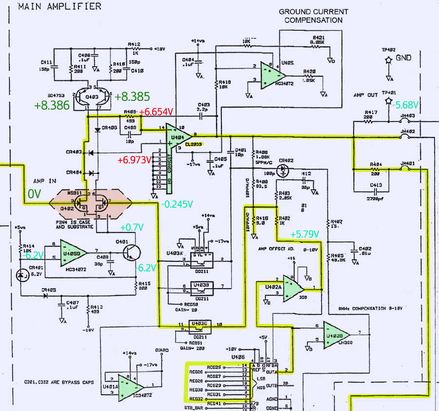
Image 2: HP 3458A AC board main amplifier schematics
Inverting input had +6.654 VDC, non-inverting input +6.973 VDC. Got it, here’s the problem. Normally functioning circuit with opamp cannot have such huge offset (319 mV!), so clearly opamp or related parts are faulty. These Elantec EL2039 600MHz op-amps are prone to fail in old units, so after replacement meter offset was gone and meter reported no problems!
Now as we have calibration ROM dump safely stored, we can try zero CAL 0 calibration. But started procedure reported failure promptly after start. Time to troubleshoot drift and offset sources, this time on A1 DC assembly board. Culprit was revealed in bad contact resistance between connecting wires from input terminal block to the socket pins on A11 Front/Rear selection board. Sorry for bad photo quality:
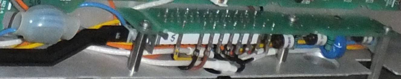
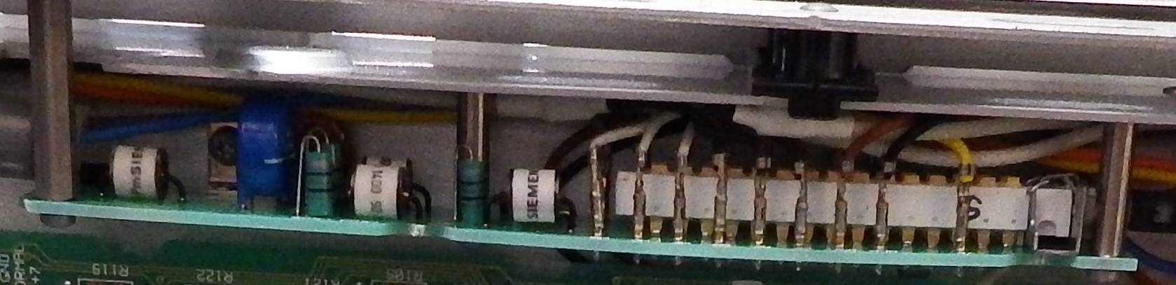
Image 3-4: A11 board with Front/Rear terminal switch and input protection network
After additional crimping of bad contacts now instrument show small, but stable NEGATIVE resistance. This is not surprising, considering initial “zero” resistance on 10 Ω range from the last calibration, which happen some 12 years ago, in 2005. This calibration constant can be read from front panel by CAL? 13 operation.
- Old CAL? 13 result : 685.324901E-03
- New CAL? 13 result : 577.790335E-03
More than 100 mΩ! Long life of the instrument, transportation did not improve these connections by any means, quite the opposite. So too big offset caused zero calibration procedure to fail, once it gets to resistance ranges self-check. After fixing and getting good connection, there were no more issues with zero calibration.
Now I’ve restored original calibration ROM contents, and used meter to test and record my most stable DCV and resistance transfer standards to obtain reference values. Now NVRAM were replaced and meter was freshly calibrated using standards and obtained values. Happy ending story, right?
Not for 8½-digit DMM monster. Like some say, “small kids – small problems…” similar apply to instrumentation. Small resolution – small problems, big resolution – big problems! After 6 month of use meter started to behave flaky and hanged often during reading TEMP? value over GPIB. Witch hunt with EMI/RFI like ferrite cores on USB cables, separate cables, shielding of instrument and PC chassis and other esoteric practices didn’t help.
Service note 3458-13A : GPIB Communication Failures Using the 3458A also didn’t help much, as it was already done on this meter before. Owner was already desperate and almost ready to give up. So as temporary solution additional LM135Z, powered from outguard logic board was added inside the meter to obtain internal temperature.
There was no drilling or chopping required, as 3458A have unused spot for BNC port for PASS/FAIL signal output.


Image 5-6: PASS/FAIL optional BNC location
After modification and port installation.

Image 7-8: Added BNC port for DIY internal temperature monitoring
Paper sticker was used to avoid confusion of connector purpose, in case service required in future. As temporary aid this additional temperature sensor did help, but not much. However additional sensor later was kept in meter permanently, as it allow to have detailed temperature log and characterization, without interrupting actual instrument operation or relay switching.
After few months of use, intermittent failures and hangs begin to occur even without any GPIB connection, right after power on. Meter started to throw RAM errors…
Gotcha!
Short dialog with owner happen promptly:
- Where did you got those Dallas NVRAMs, we used for replacement? In a trash bin?
- I got them at fleaBay…
- !..Where..?!$#@
- Some random seller, not the cheapest one. It looked legit, I promise!
Checking seller’s feedback.. Large Chinese seller, hundreds thousands sales, score over 99%, fancy nice ESD-protected packaging with shiny labels and stickers. What could be wrong…
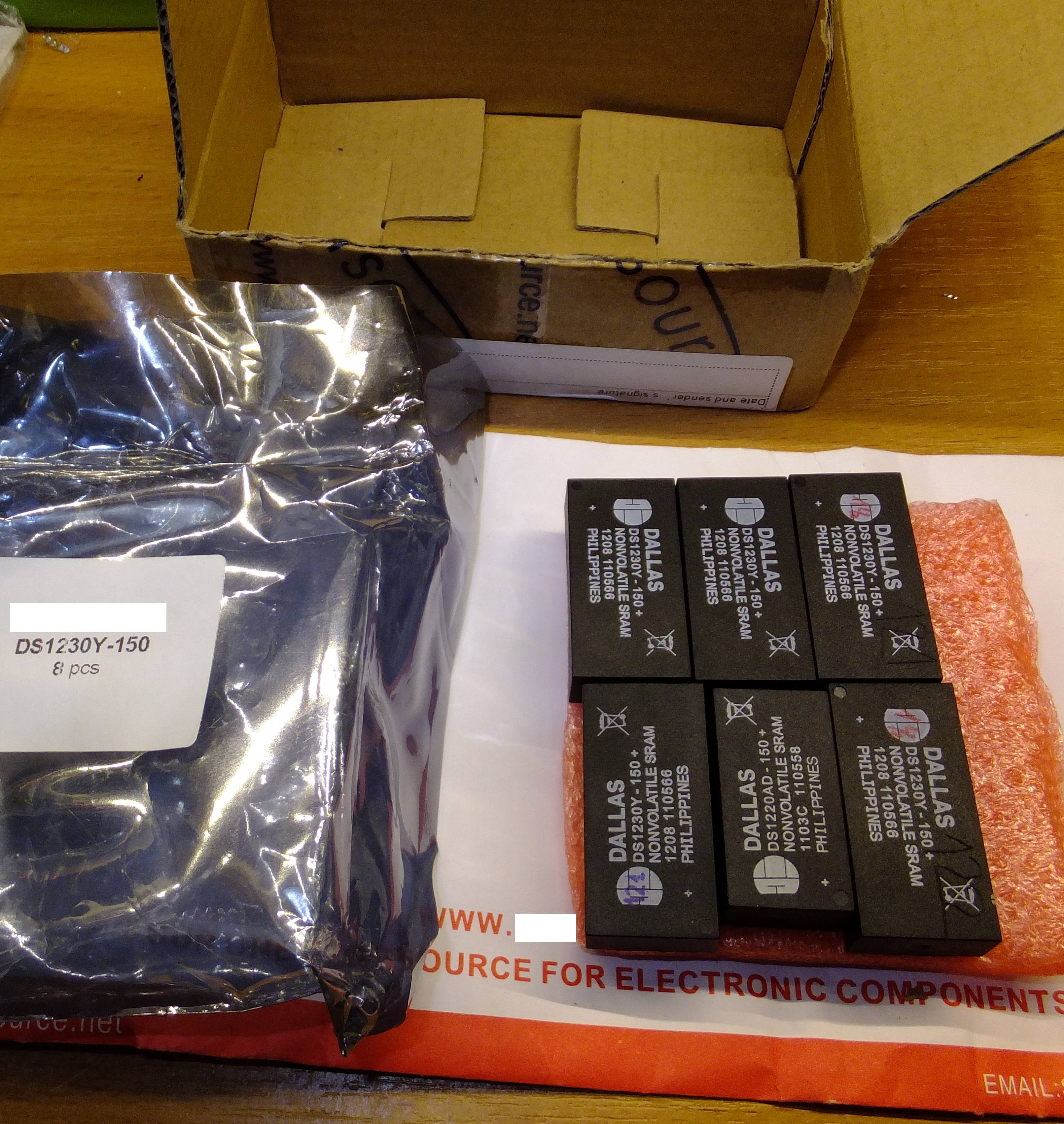
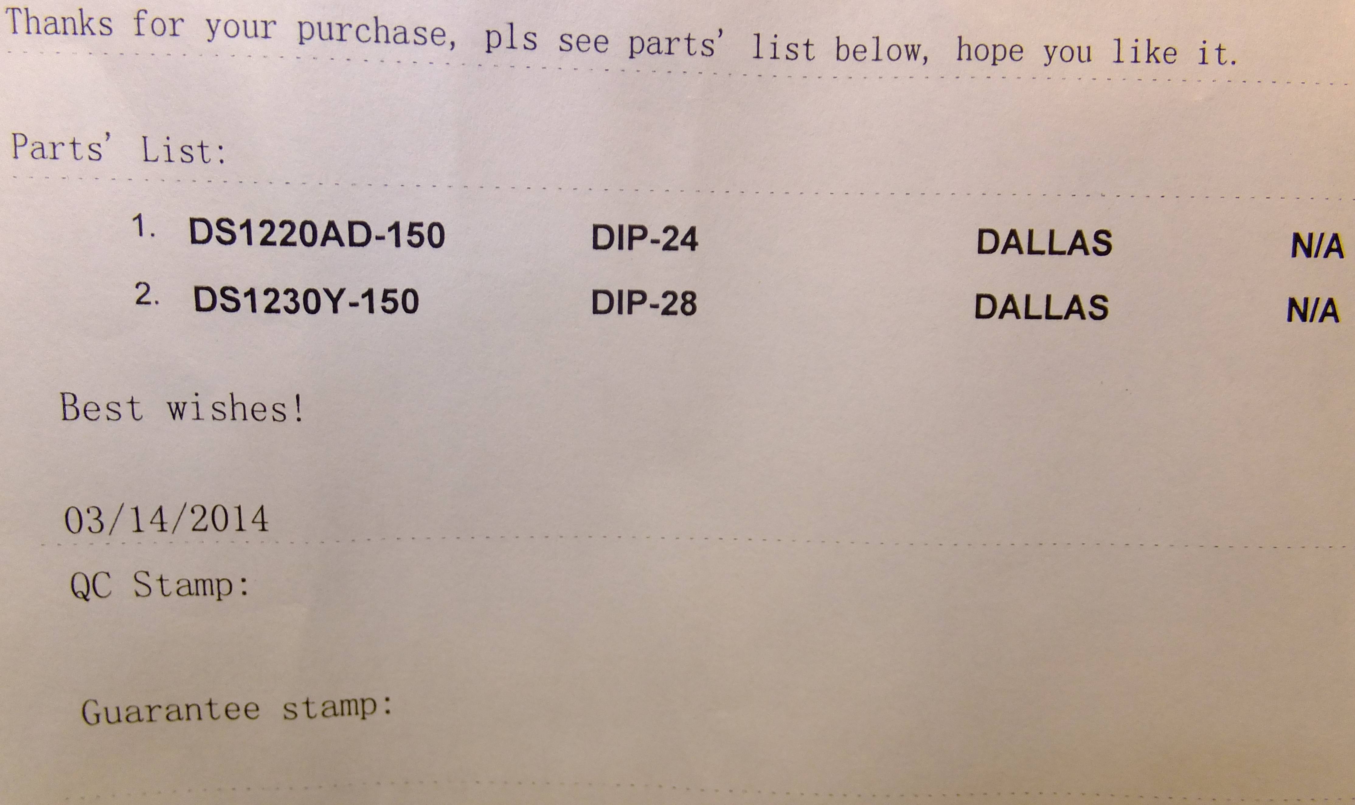

Image 9-11: Counterfeit NVRAMs from eBay
Well, everything nice and shiny, but under the wrap is just pure crappy counterfeit. There is no point to argue with seller, especially after half a year of the sale. So for applications like replacement in these expensive meters, it’s always worth to get a genuine part, right from the manufacturer. However price bit high at USD $17/pcs, and there is no fun buying new part and doing simple replacement.
So here we go for Plan B, removing Dallas NVRAM once and forever! No more dying battery or lost calibration data.
FRAM modification for HP 3458A
So what is required for this? Please relax, no need to cut or butcher HP 3458A boards. Owners who already have sockets for NVRAMs already don’t need any reworks on meter itself. Also need to buy FRAM chip FM16W08 and adapter board SO28-DIP28. All modifications will be performed on this adapter interposer board.
Now, follow step-by-step procedure, so nothing gets mixed up. Use ESD-safe tools and bench setup, so we don’t zap the meter’s board by accident.
1. Desolder original calibration NVRAM U132, read its contents and save dump on PC. Wise to backup dump somewhere else too, in case Dallas NVRAM/HDD gets damaged, etc.
2. Solder decent quality collet-type DIP24 panel on U132 location at A5 PCBA. Don’t try to cost down few cents, where it can cause loss of 2000$ worth calibration data.
3. Populate FM16W08 on SO28-DIP28 adapter board. Don’t cut or add anything at this point.
4. Install adapter board with FM16W08 into programmer and program dump we saved in step 1. As FM16W08 is four time larger capacity than DALLAS DS1220, write dump into lowest bank, or expand binary dump to fit larger size. If this step confuse you, better to leave 3458A unmodified and learn some firmware basics first. Better be safe than sorry…
5. Now take adapter with FRAM out and cut trace from FM16W08’s pin 23 to adapter pin. Again, this trace cut is done on adapter board, NOT the A5 meter’s controller.

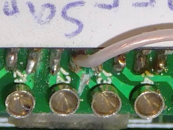
Image 28-29: Cut trace to pin 23 on adapter, AFTER programming ROM dump
6. Now jump-wire pin 23 of FRAM chip to adapter’s pin 1.
7. Turn adapter upside down and …
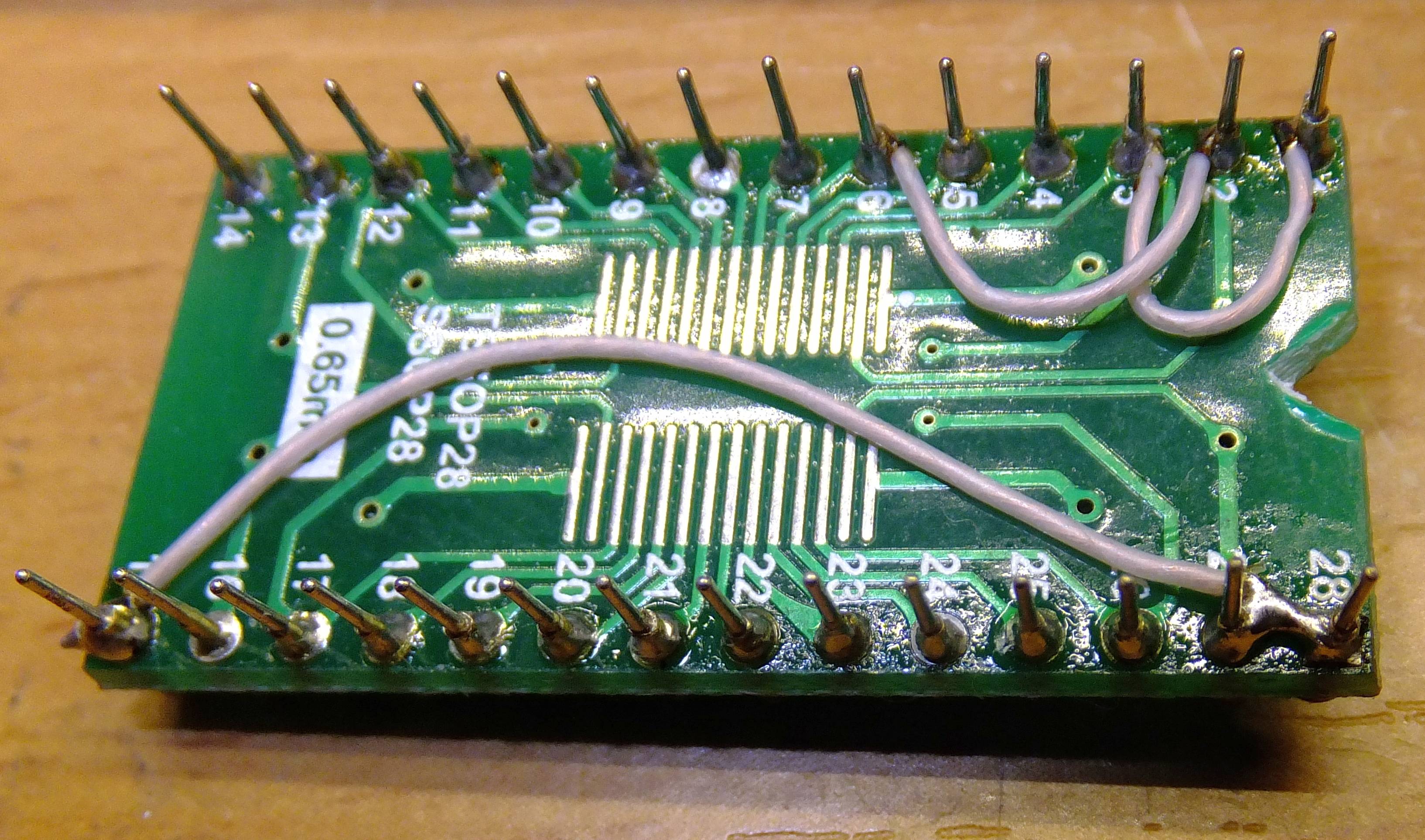
Image 30: Jump-wired connections on the bottom side
8. Connect adapter’s pin 1 and 2 together and jump wire it to pin 14 (GND). Don’t confuse pin numbering, on my adapter numbering on bottom side was mirrored! Better to check many times, than destroy expensive 3458A outguard controller once.
9. Jump-wire adapter’s pin 26 and 28 to supply power to FRAM IC.
10. Jump-wire adapter’s pin 23 and 27 to route ~WE signal to correct pin.
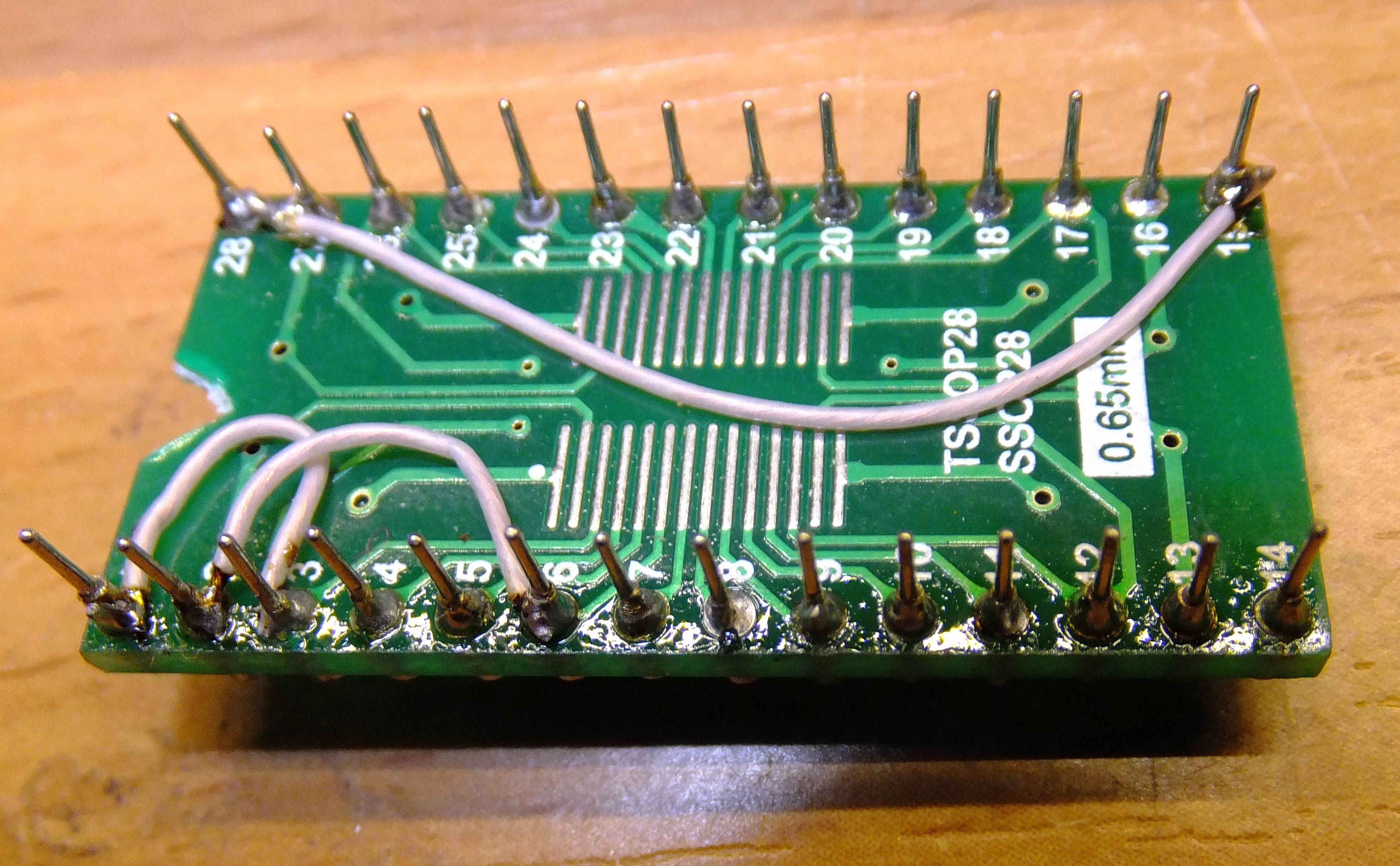
Image 31: Jump-wired connections on the bottom side
11. Check everything again, check pin numbering of IC and pin numbering of adapter. Make sure there are no shorts or open jump-wires. If everything looks good, install adapter into meter. Pin 14 of adapter fits pin 12 of socket on A5 PCBA, to match ground to ground. Pins 1,2,27 and 28 should be floating and hanging in the air, not connected.
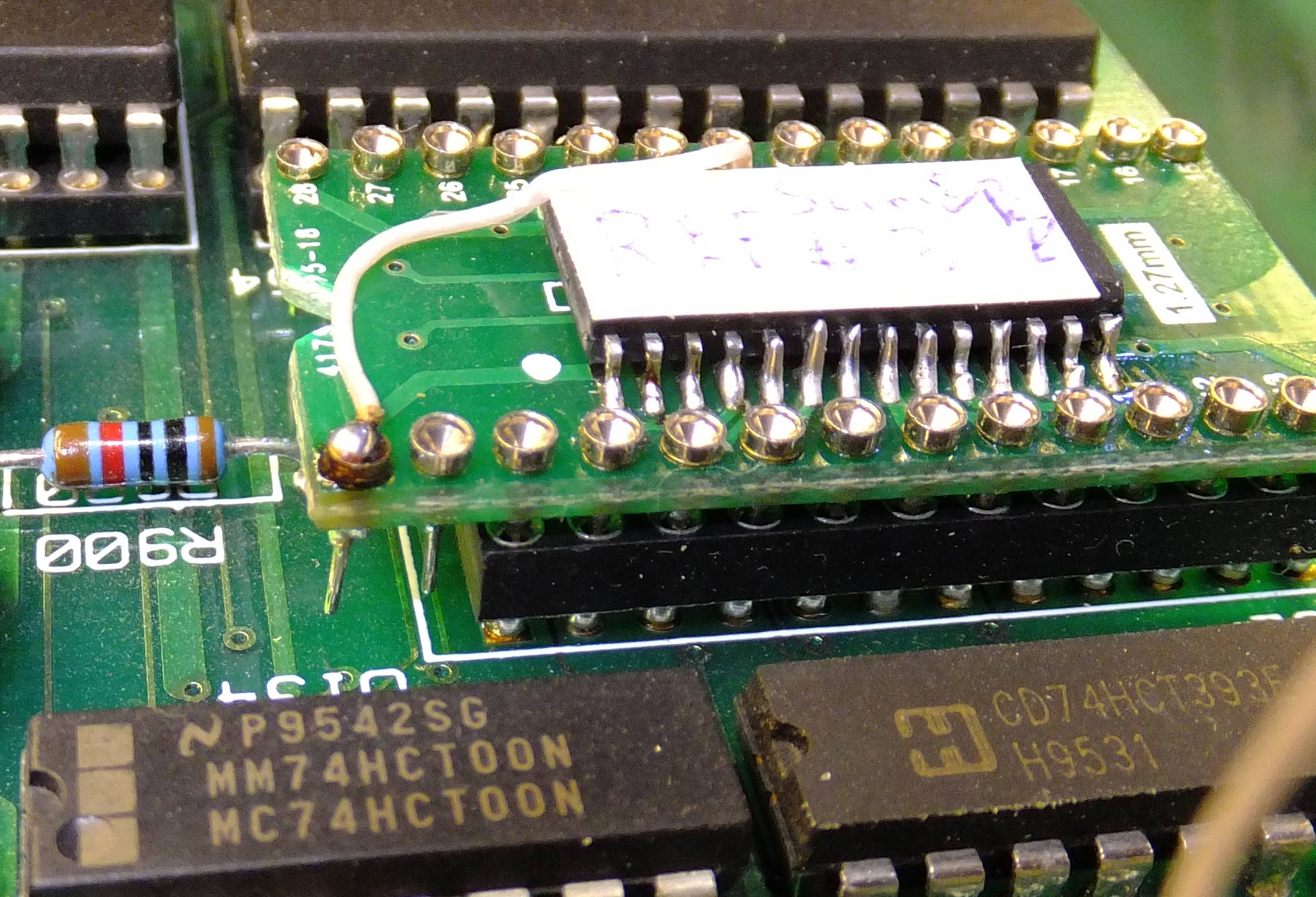
Image 32: Installed FRAM module in meter’s A5 PCBA
12. Check everything again. Power the meter on, and everything should be working well without any error messages. If something wrong, turn power off and locate mistake. I did this operation three times on three different adapters and it worked every time.
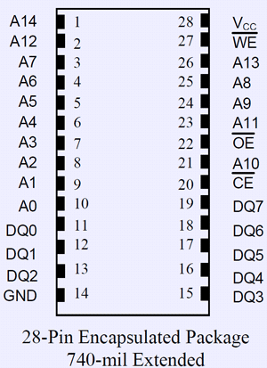
All these steps are shown in schematics below:
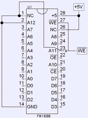
Image 33: Schematic for final CALROM adapter with FRAM RAMTRON FM16W08
Now, after a year of happy meter’s operation with FRAM in place of calibration ROM, time to go one step further and replace main U121,U122 RAMs similar way, using RAMTRON FM18W08 instead.
Procedure is next:
1. Install sockets, similar to previous step in case of calibration ROM. Only difference – sockets are DIP28 type.
2. Read original NVRAM contents. This is to keep same macros/meter settings intact. If you want start fresh, you can omit this step.
3. Populate FM18W08 on same adapters like in calibration ROM case. Pinout of FM18W08 matches original Dallas DS1230, so no reworks or jump-wiring necessary.
4. You can also do the same for additional RAM chips to install in empty Option 001 sockets.
| DS1230Y NVRAM | FM18W08 FRAM |
|---|---|
 |
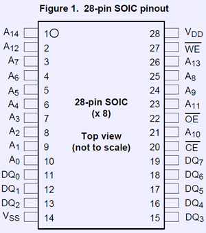 |
Table 1: DS1230Y vs FM18W08
5. Now install new FRAM adapters into meter, check correct orientation.
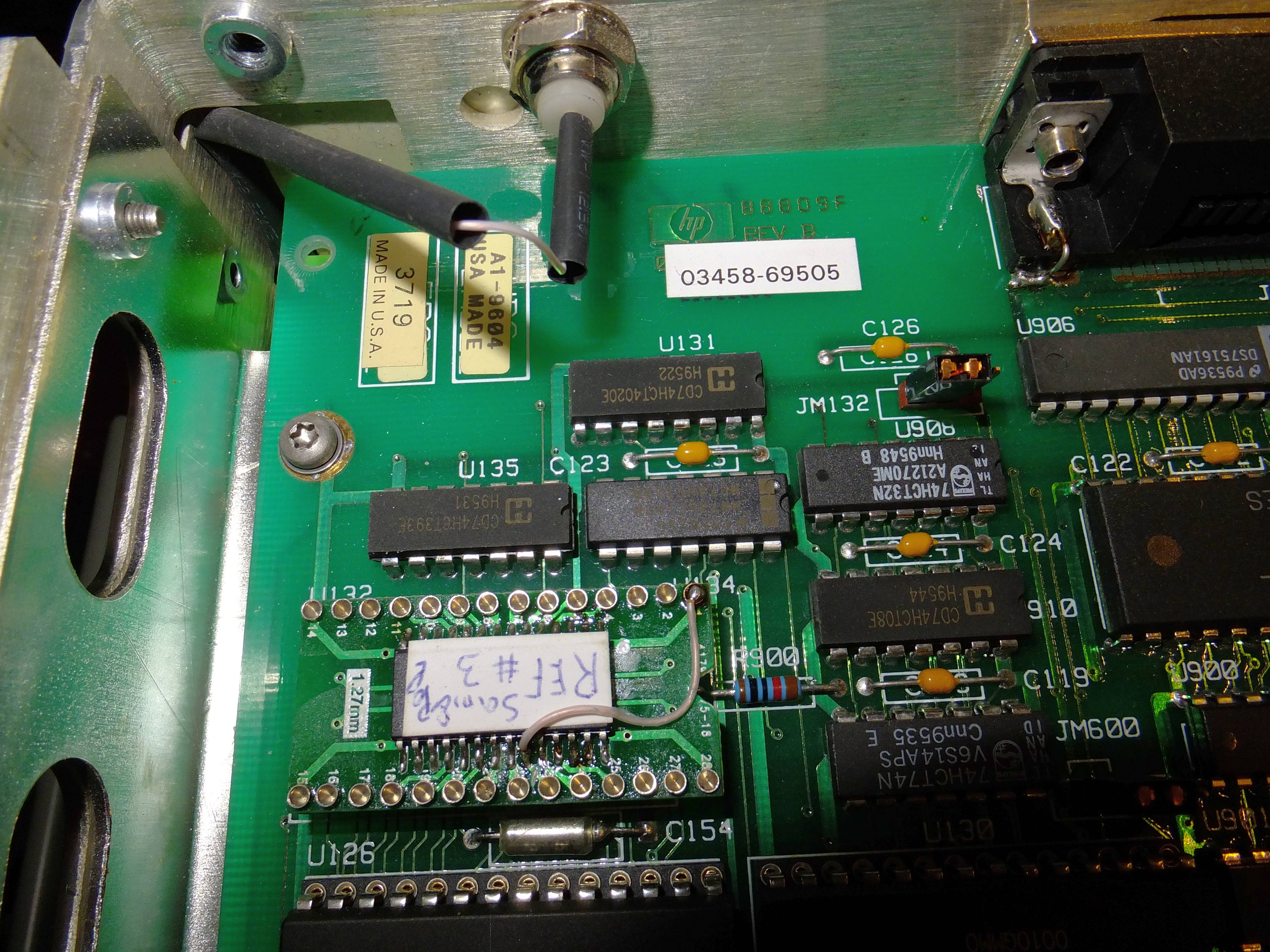

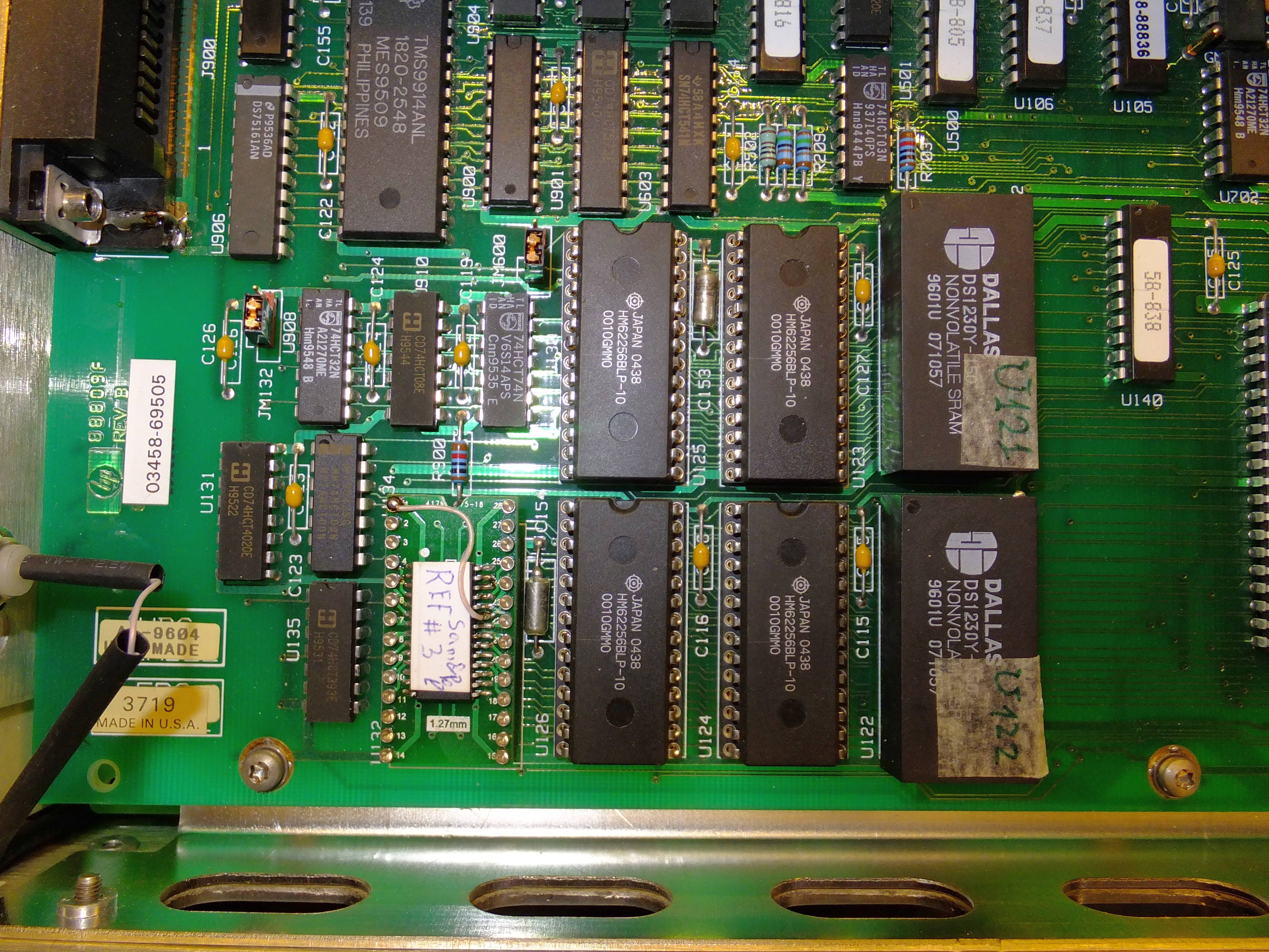
Image 34-35: FRAM replacement for Calibration ROM
6. Turn meter on, everything should work normally. Self-test should give correct SELF-TEST PASS. Now it’s time to celebrate!
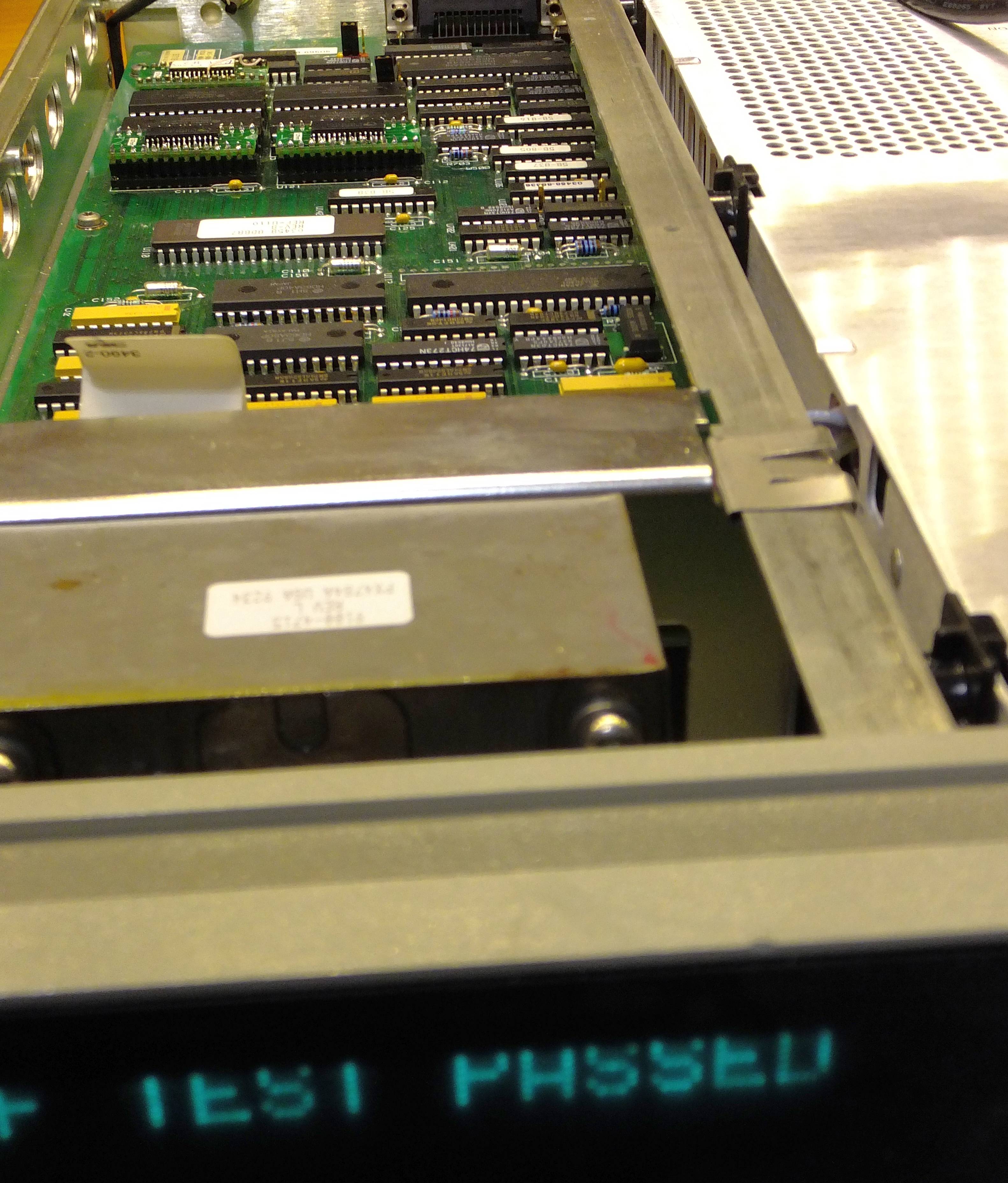
Image 36: Self-diagnostics result – PASS!
This meter works with FRAM memory since 31 December 2015, with zero issues so far. No more depleted battery worry.
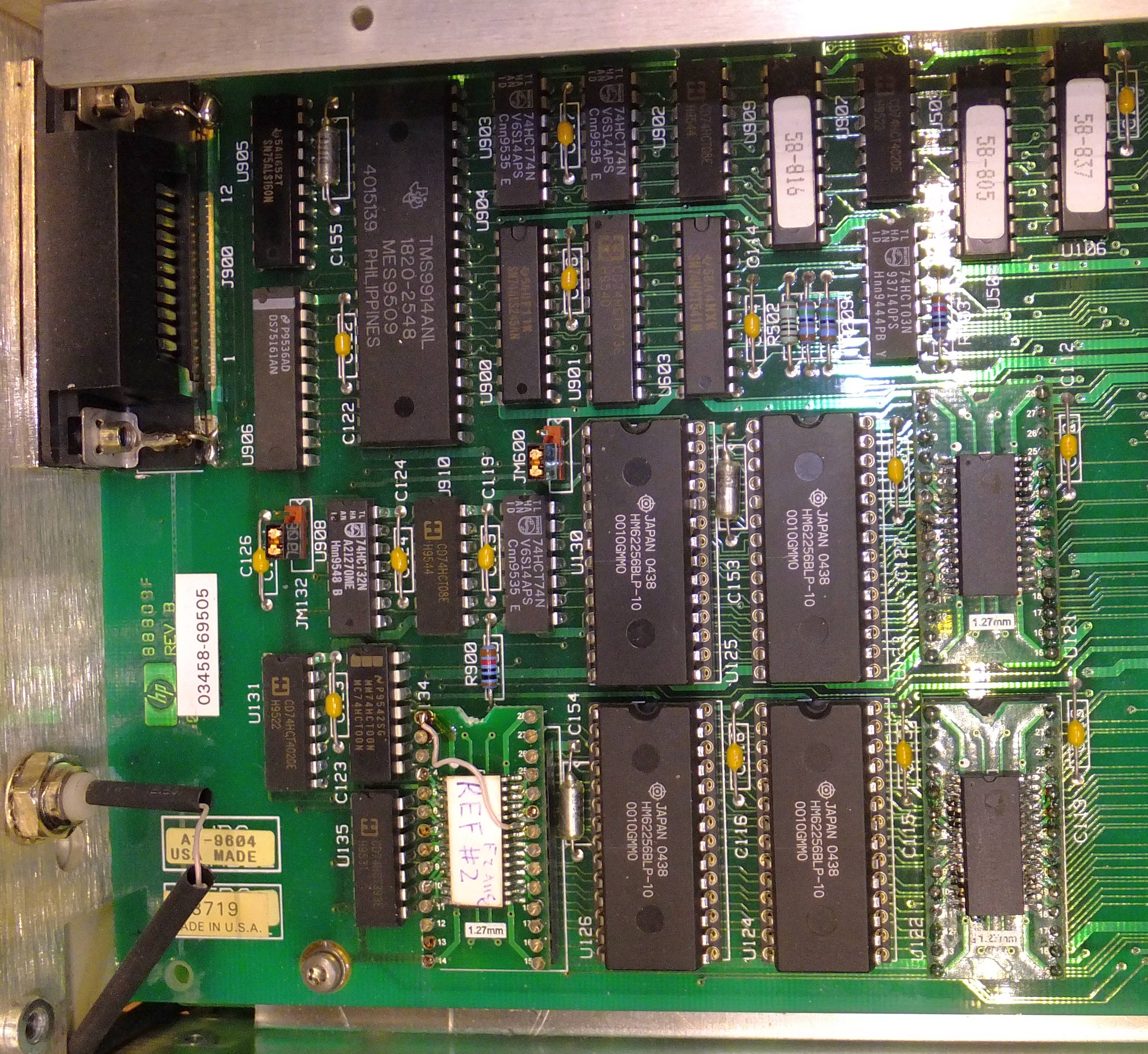

Image 23-26: Happy meter with battery-free FRAM modules
Reference boards tests
Tests? What reference tests? Ah, forgot about this…
Long story short, I already had experience with building LTZ1000-based DC voltage references. But I didn’t have small size precision 100 KΩ resistors. You might get the hint here, right? Thing is, it’s a known fact that original HP 3458A LTZ1000A reference have high oven temperature, almost +95 °C, which cause rather bad long-term stability and aging.
Common modification is to install extra 100 KΩ resistor in parallel with R411, to have oven temperature reduced. Lower temperature improves long-term stability of 3458A on DCV from <8 ppm/year to better than <2ppm/year. Example of this procedure was done and shown on first xDevs.com HP 3458A meter repair project.
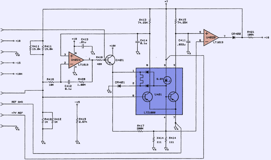
Image 12: Original A9 PCBA schematics from HP CLIP
But I did not have good <3 ppm/°C resistor, so decided to build own reference module with calculated temperature setting resistor network. Schematic differences from original design:
| Component Designator | New value |
|---|---|
| R411 | 13.3 KΩ |
| R412 | 1.01 KΩ |
| U402 | MAX44246 |
| R414 | 113 Ω |
| R413,R415 | 70 KΩ |
| R417 | Not installed |
Table 1: Different parts used in DIY LTZ1000A reference
R417 was not used, maybe that’s an issue, but to know for sure lot of time for testing required. I have location for this resistor on the board, so it can be added in future if such need arise.
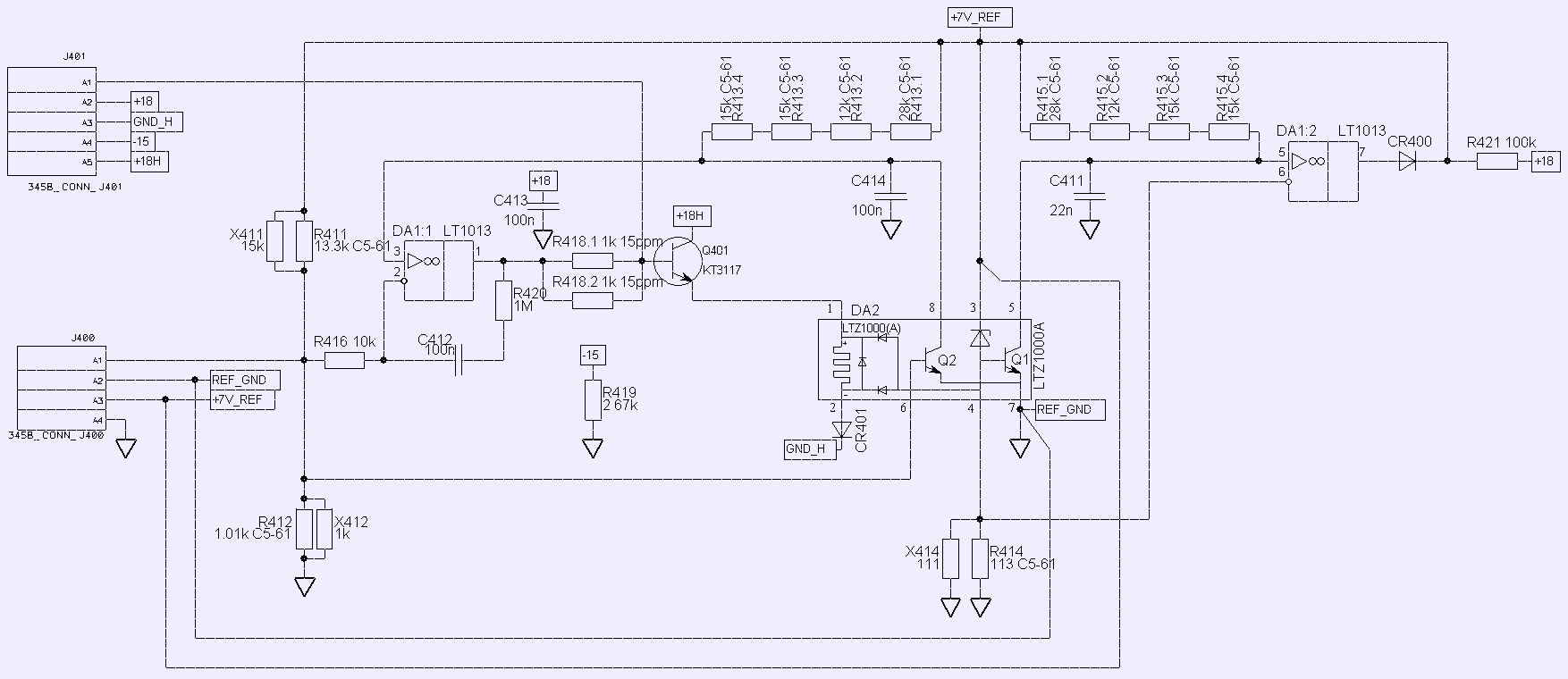
Image 13: DIY LTZ1000A-based voltage reference
Here’s the result of DIY module.
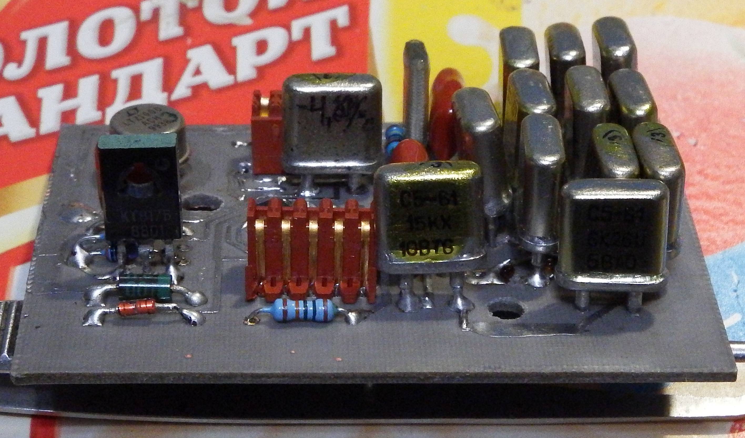
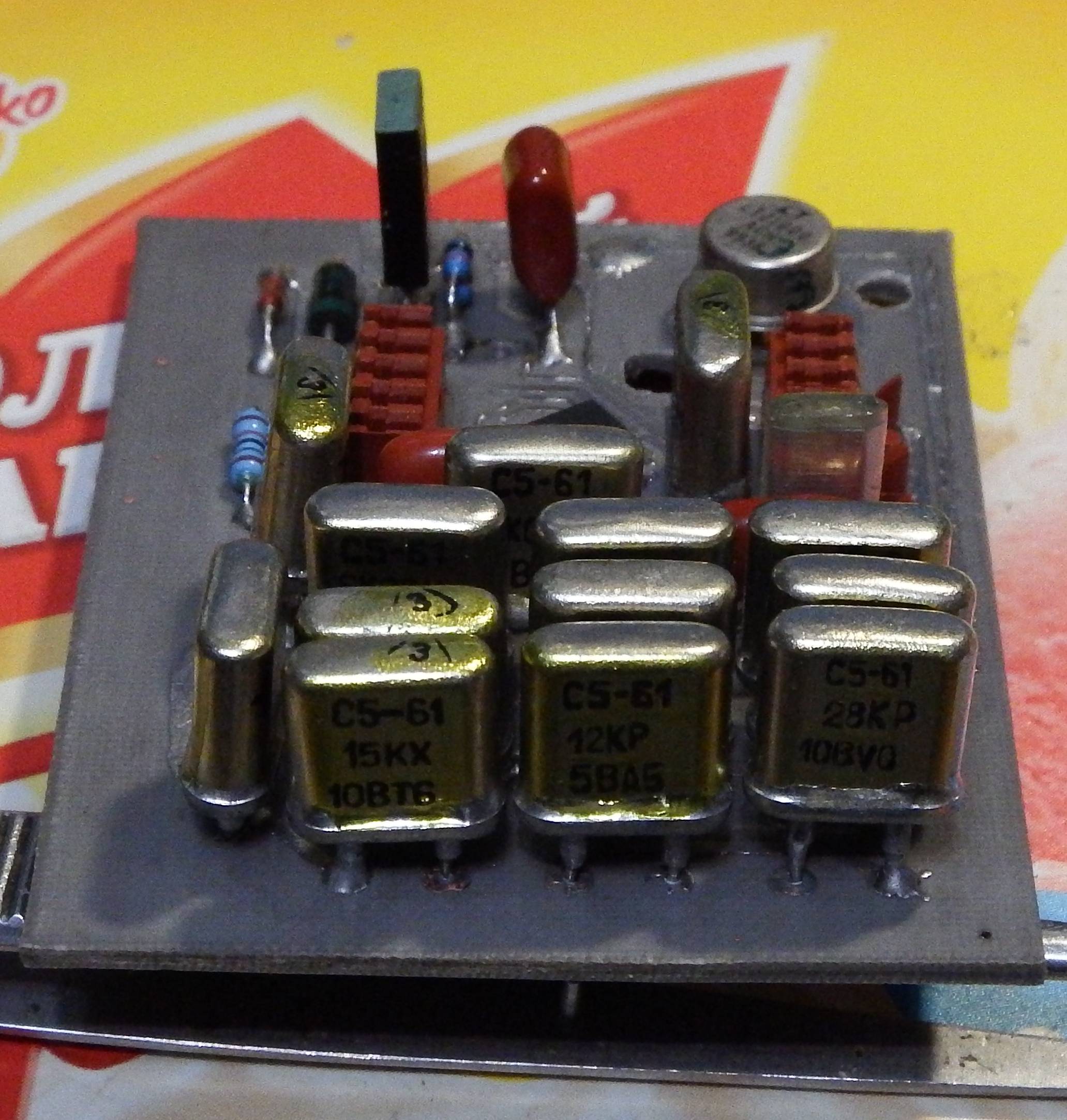

Image 14-16: Module construction and prototype assembly
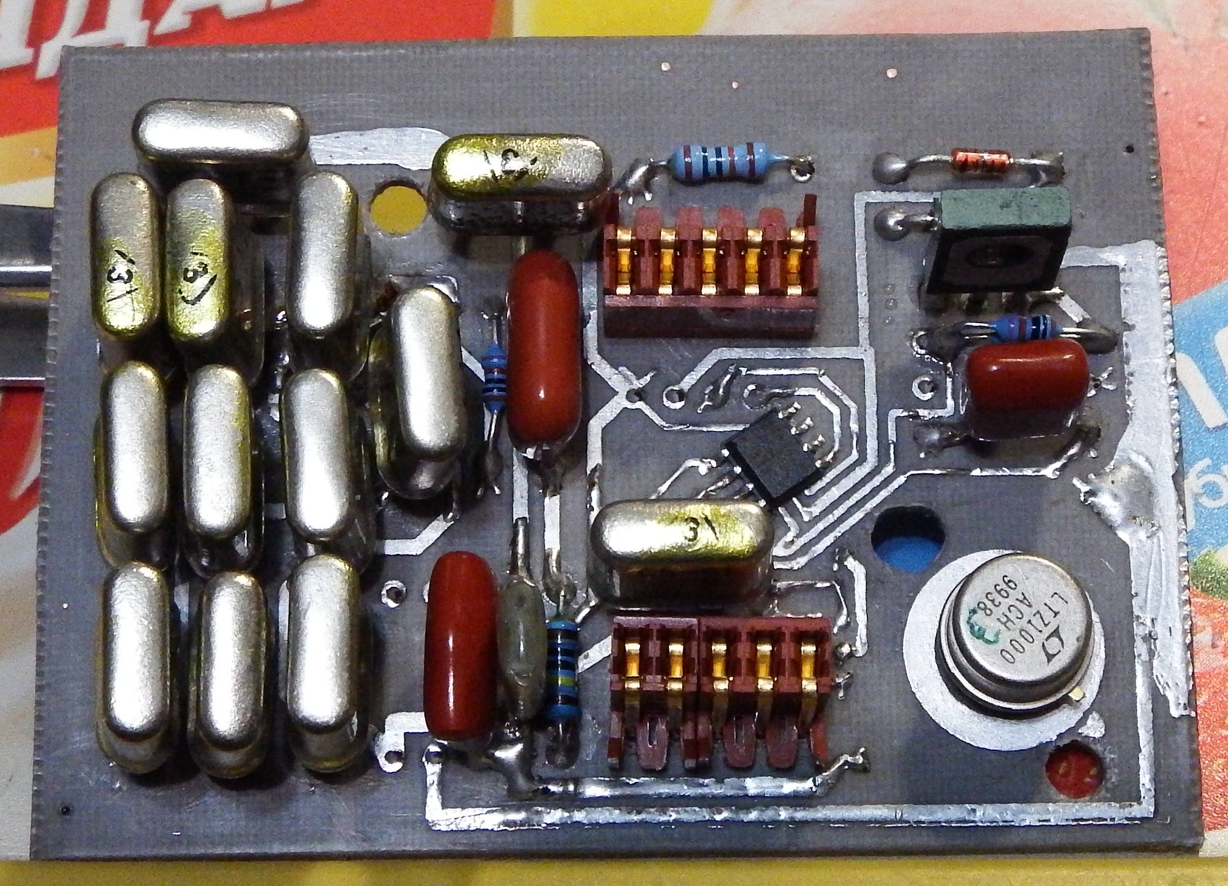
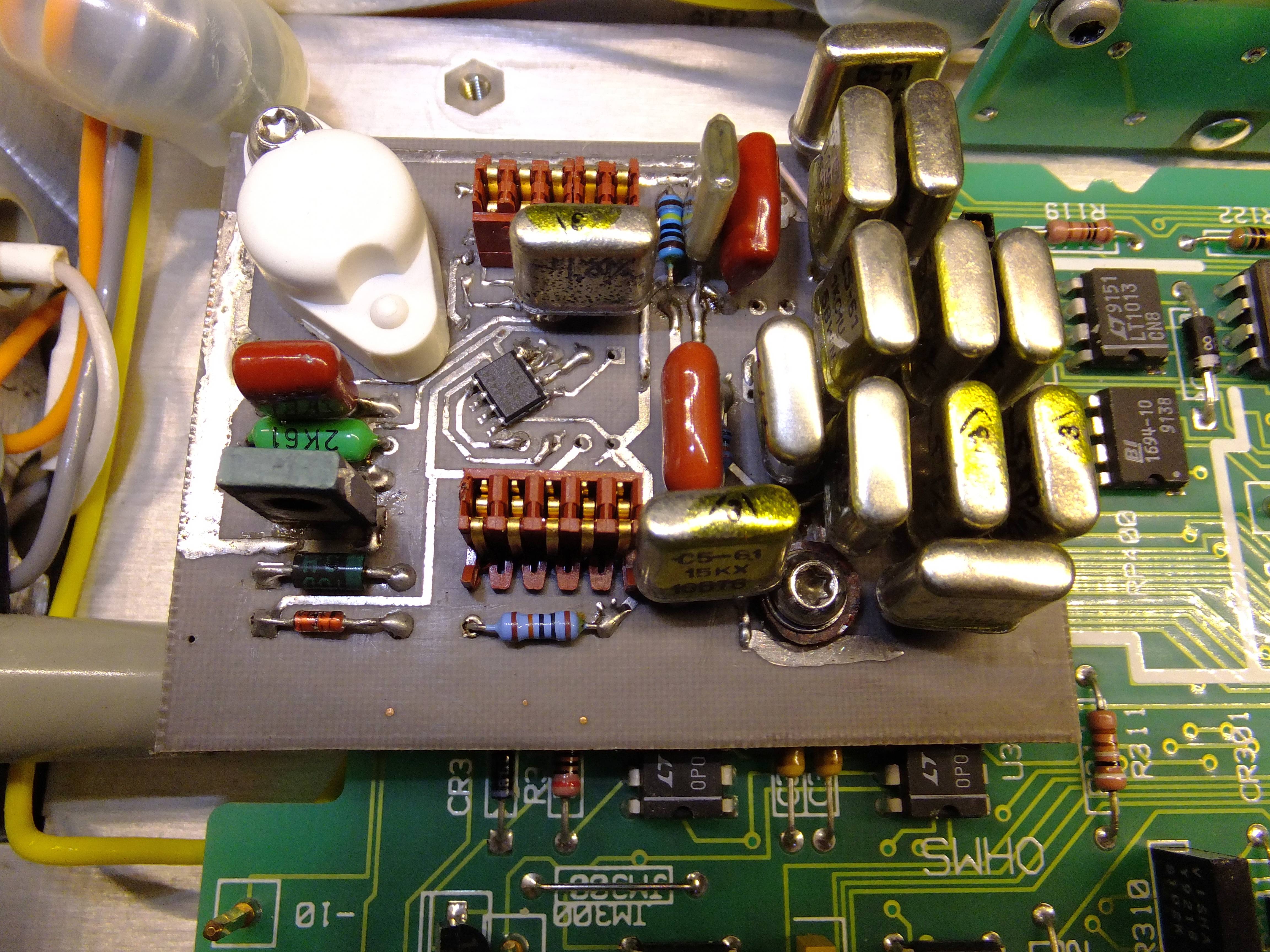
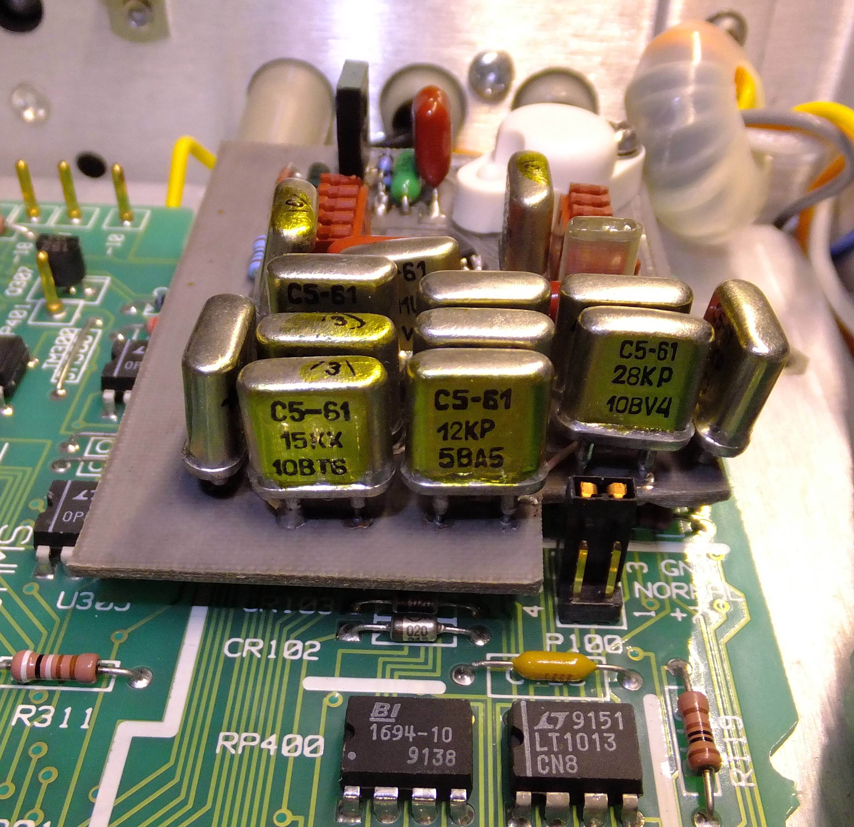
Image 17-19: DIY module installed in HP 3458A meter
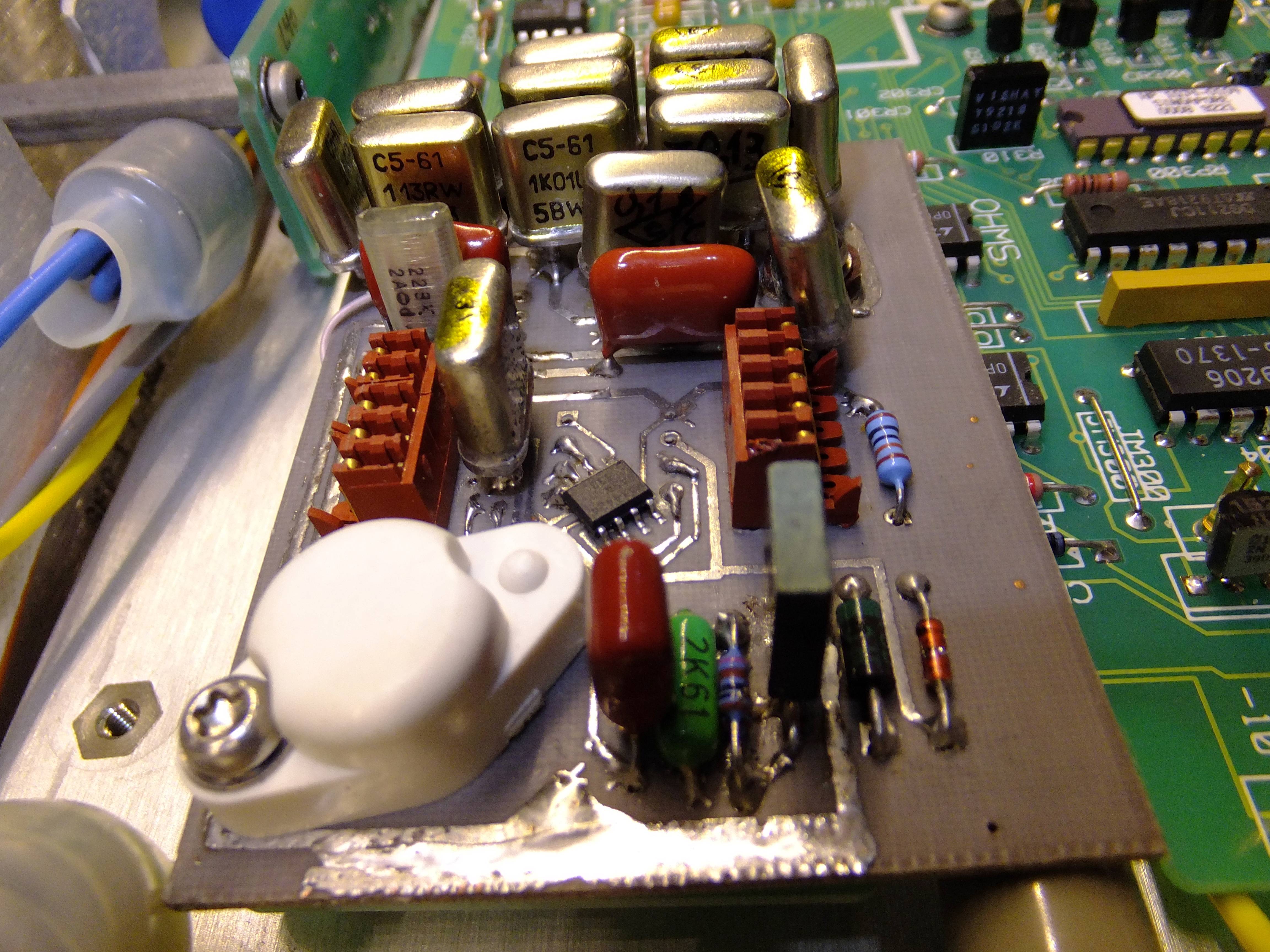
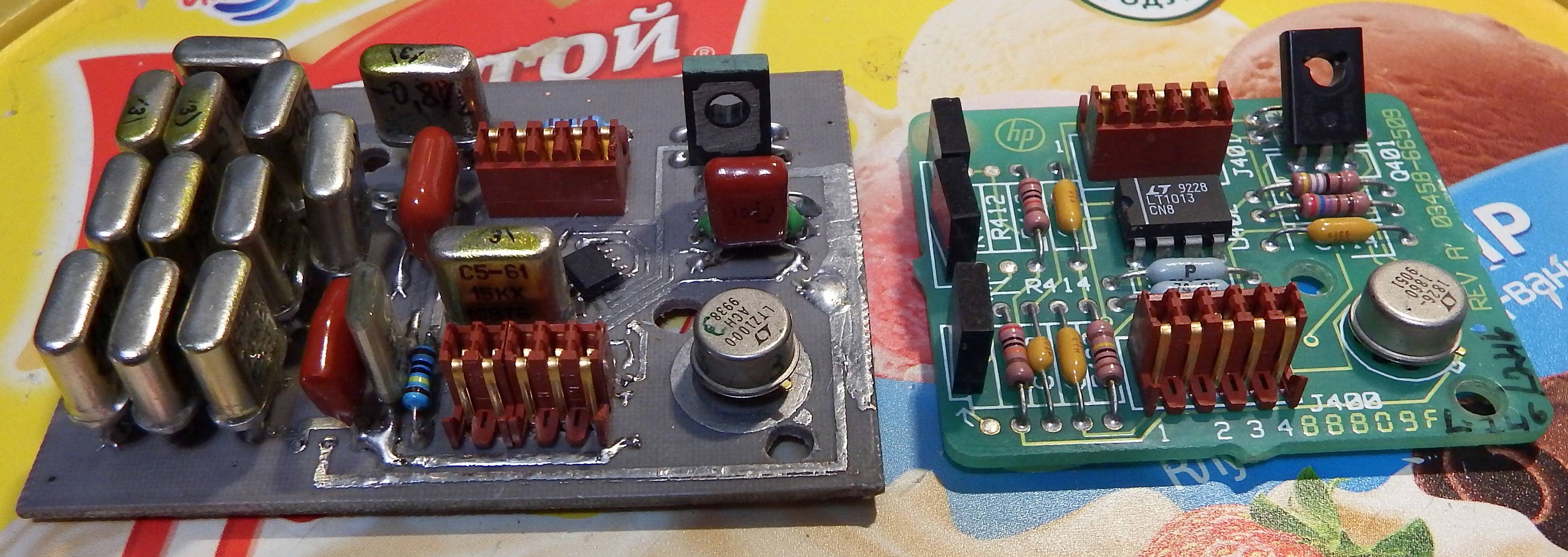
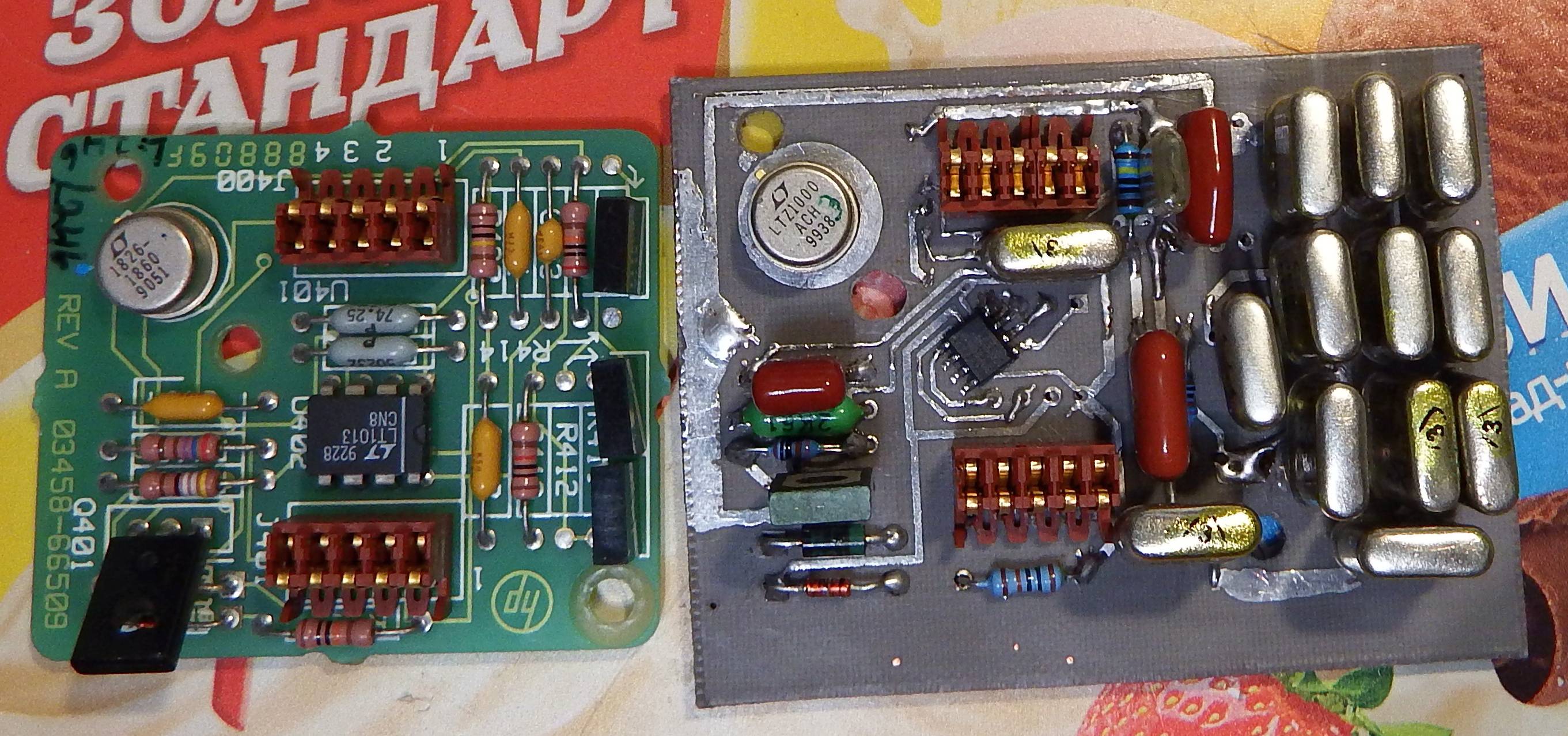
Image 20-22: DIY module comparison with HP A9 PCBA
As you can see, there was minor oversight with interference to jumper P100, so one of the resistors had to move to allow cutout. Glad I left some space open, it was just right.
After installation of new DIY module everything worked well, so I used spare FRAM CALROM adapter board (total 3 pcs made, so CALRAMs can be swapped for experiments).
I had two reference boards to test with. Two native A9’s standard 03458-66509, one of which is original from meter, second was bought on fleBay, and third one is DIY.

Image 27: Voltage references collection with related CALRAM modules
So now with replacement of just A9 board and CALRAM adapter we can do any experiments with the meter, calibrate, re-calibrate, over-calibrate. :) To revert back to original state – just install original A9 and original CALRAM data module, and valid calibration is back, even calibration counter stays same.
Temperature coefficient tests
Since meter is not mine, and available for limited amount of time, only this test for temperature coefficient of 10V DCV range function was performed. Test was repeated three times with all three voltage reference boards.
Such sub-ppm level tests are difficult and usually take long time. In this case small compromise on test time was done to speed things up. After each DC reference swap in 3458A, box was left on for few hours to get temperature equilibrium before actual data collection started, with re-calibration and checks. Usually after repair or long off-times few weeks of running time recommended time period, mentioned by Agilent in 3458A’s Service note 18-A.
To make best measurements one would collect external DC voltage reference with constant temperature or with same begin/end temperature, to get better confidence that we test stability of meter, not the source. I was not be able to perform this, closing up calibration cycle, as finishing data collection at same temperature as test started was not possible due to time reasons.
Temperature coefficient of used DC source (based on LTZ1000A as well) measured and calculated at -0.063 ppm/°C, so this correction was simply subtracted from voltmeter samples to get meter-only stability. Separate measurements of source reference temperature was not logged, but modified LT135Z thermal sensor data were used instead. This was possible to do because internal meter is closely tied to ambient temperature, with delay and bit of smoothing due to large thermal mass and thermal inertia.
Fan grill was also cleaned after each replacement of DC reference board, to make sure temperature delta stay same thru all comparisons. Normally 3458A with clean filter and good fan have ~11-14 °C difference between internal temperature, such as reported by TEMP? reading and ambient room temperature.
Summary results are provided in table below. All data confirms proper meter operation and temperature coefficient for 10V DC range well within specification.
| Used reference A9 for test , ppm/°C | Original A9, high Toven | Original A9, lowered Toven | Used A9, low Toven | DIY LTZ1000A REF, low Toven |
|---|---|---|---|---|
| DCV temperature coefficient, lowering temperature | 0.14 | 0.202 | 0.133 | DNT |
| DCV temperature coefficient, raising temperature | 0.198 | DNT | 0.202 | 0.176 |
| DCV temperature coefficient, averaged | 0.169 | DNT | 0.1675 | DNT |
Table 2: DCV Tempco measurement results
As we can see, reduced oven temperature for A9 reference does not actually improve temperature coefficient of the DC voltage function of the meter. This is expected, as tempco of reference itself is better than ±0.05 ppm/K and not a limiting factor. Other components like main input DC amplifier, ranging resistors and relays, physical PCB and wiring connections contribute larger errors into overall voltage temperature coefficient.
In this particular meter it was decided to keep original high oven temperature A9. Another used A9 reference will be used as standalone reference with lower temperature. Sometime later I’ll try different R417 values on DIY LTZ1000 reference to see more test data.
Some test result charts shown below. All measurements performed with NPLC 50 on fixed range.
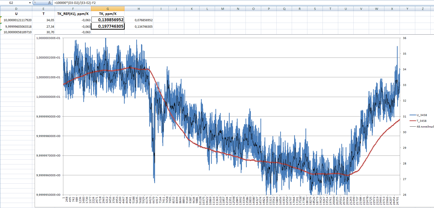
Chart 1: Test chart with original high-temp A9
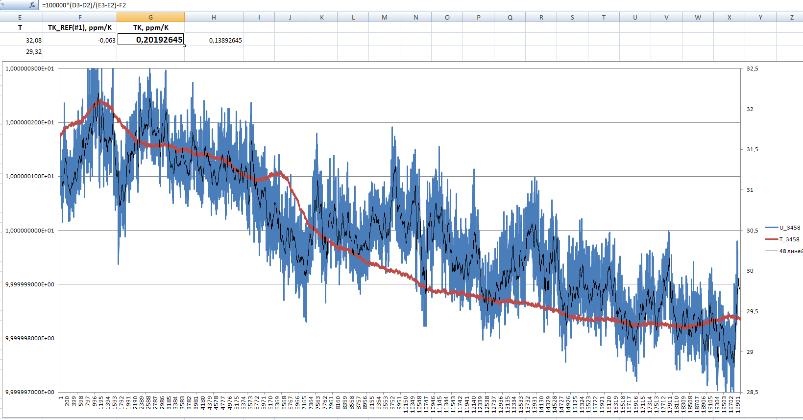
Chart 2: Test chart with original low-temp A9
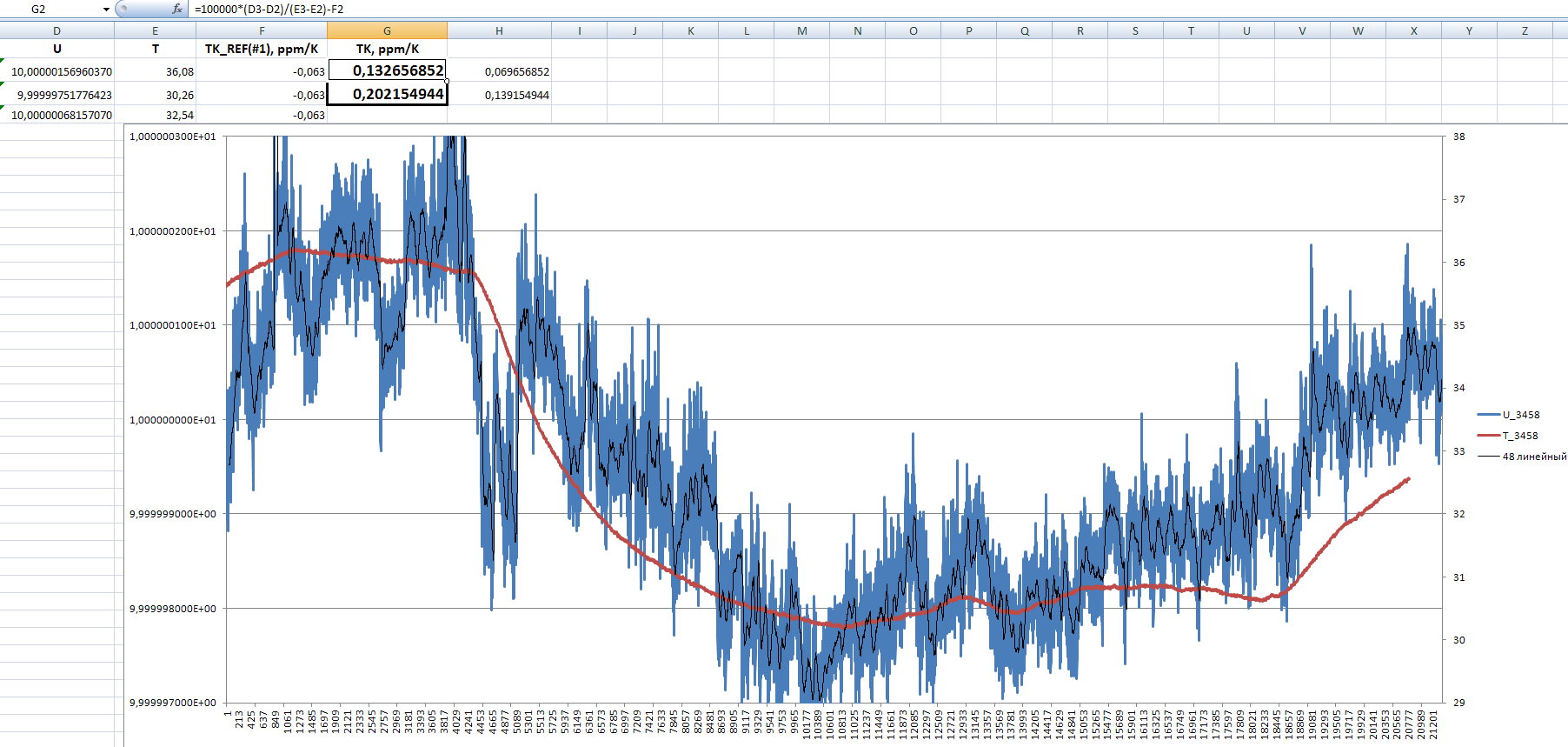
Chart 3: Test chart with used low-temp A9
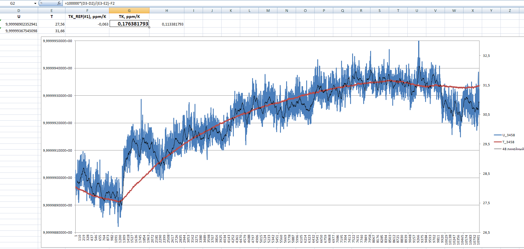
Chart 4: Test chart with DIY LTZ1000 reference
All data samples are spaced in 2.052 seconds interval, both temperature and voltage.
Summary and repair results
That’s it for now, and yet another old (but not obsolete!) HP 3458A is back into good service and owners happy use.
Other related HP 3458A articles and references
- HP 3458A CLIP
- HP 3458A Multimeter Assembly Level Repair Manual, Edition 2
- xDevs.com : HP 3458A restoration project worklog
- xDevs.com : Repair log of reader’s HP 3458A precision DMM
- xDevs.com : Repair of second HP 3458A metrology DMM
- xDevs.com : Testing of LTZ1000 reference, little jumper, or sharks in voltage references world
- Keysight 3458A Digital Multimeter, 8½ Digit
© TEKTRON, January 2017
Projects like this are born from passion and a desire to share how things work. Education is the foundation of a healthy society - especially important in today's volatile world. xDevs began as a personal project notepad in Kherson, Ukraine back in 2008 and has grown with support of passionate readers just like you. There are no (and never will be) any ads, sponsors or shareholders behind xDevs.com, just a commitment to inspire and help learning. If you are in a position to help others like us, please consider supporting xDevs.com’s home-country Ukraine in its defense of freedom to speak, freedom to live in peace and freedom to choose their way. You can use official site to support Ukraine – United24 or Help99. Every cent counts.
Modified: Oct. 26, 2025, 12:02 a.m.
References
- Cypress FM18W08
- Maxim/Dallas DS1230AB
- Cypress FM16W08
- LM135/335 temperature sensor
- 3458A Multimeter Assembly Level Repair Manual, Edition 2
- 3458A Multimeter CLIP with schematics
- Repair log of reader's HP 3458A precision DMM
- EEVBlog : HP3458A Schaffner mains line filter failure
- Keysight product page : 3458A Digital Multimeter, 8½ Digit
- xDevs.com HP 3458A restoration worklog (first unit)
- xDevs.com KX Voltage reference design based on LTZ1000
- EEVBlog : Discussion on repair of this meter