Contents
- Intro
- Disclaimer
- Manual references
- Initial inspection and basic disassembly
- Transformer hum
- Firmware
- Update from reader on newer DMM6500
Intro
Common industry-known 6½digit DMM from Keithley, Model 2000 just got refreshed with new -blingy fancy design, as Tektronix/Keithley DMM6500. However this is not just a simple facelift, but actually meter redesigned from scratch. Tektronix released this DMM6500 in April 2018. Let’s see what makes it tick.
Other brand competitors for this meter would be old Fluke 8846A and Keysight 3446x series.
| Function | Ranges | Accuracy |
|---|---|---|
| DC Voltage | ±10mV, ±100mV, ±1V, ±10V, ±100V | Best 1 Year Specification: ±25 ppm + 2 |
| AC Voltage | ±100mV, ±1V, ±10V | Best 1 Year Specification: ±25 ppm + 2 |
| DC Noise spec | 6 nV & 25s NPLC5, FILT, 10mV, 2.5µV & 1s NPLC1, FILT, 10V | |
| Resistance 4W | 1 Ω – 100 MΩ | |
| DC Current | 10, 100 µA, 1,10,100 mA, 1,3,10 A | |
| AC Current | 100 µA, 1,10,100 mA, 1,3,10 A | |
| Capacitance | 1,10,100 nF, 1,10,100 µF | |
| Digitizer | Up to 1 MSPS for V/I | |
| Diode | 10V clamp (10,100 µA, 1,10 mA) | |
| Temperature | -200°C to +1820°C, Type J,K,N,T,E,R,S,B | Accuracy: ±0.2 °C, 0.001°C resolution |
| ADC linearity | ±0.8ppm of reading + 0.5ppm of range | |
| Input impedance | >10 GΩ for 10mV-10V ranges |
Table 1: Model DMM6500 measurement functions

Image 1: Keithley DMM6500 front interface with touchscreen TFT LCD.
This meter
Let’s also look on other market competitors:
| Specification | Tektronix/Keithley DMM6500 | Keithley 2000 | Keysight 34465A | Keithley 2001 | Keithley DMM7510 | Keithley 2002 |
|---|---|---|---|---|---|---|
| Resolution | 6½ digits | 7½ digits | 8½ digits | |||
| ACAL function | No | No | Yes | ACV only | Yes | ACV only |
| Form-factor | Half-rack 2U 19” instrument | |||||
| MSRP | $1140 USD | $1140 USD | $1430 USD | $4600 USD | $4355 USD | $6150 USD |
Table 1: Comparison summary to other popular meters on market
Disclaimer
Redistribution and use of this article or any images or files referenced in it, in source and binary forms, with or without modification, are permitted provided that the following conditions are met:
- Redistribution of article must retain the above copyright notice, this list of conditions, link to this page (/review/dmm6500/) and the following disclaimer.
- Redistribution of files in binary form must reproduce the above copyright notice, this list of conditions, link to this page (/review/dmm6500/), and the following disclaimer in the documentation and/or other materials provided with the distribution, for example Read-me file.
All information posted here is hosted just for education purposes and provided AS IS. In no event shall the author, xDevs.com site, or any other 3rd party, including Keithley or Tektronix be liable for any special, direct, indirect, or consequential damages or any damages whatsoever resulting from loss of use, data or profits, whether in an action of contract, negligence or other tortuous action, arising out of or in connection with the use or performance of information published here.
If you willing to contribute or add your experience regarding instruments repairs or provide extra information, you can do so following these simple instructions
As usual, all photos are clickable for high-resolution version.
Manual references
Reference manual, Rev.A April 2018
Quick Start Guide, Rev.A April 2018
DMM6500 and DAQ6510 declassification manual
DMM6500 in a Model 2000 Application, emulation and migration
DMM6500 Specifications, Rev.A, April 2018
TSP Application Intro DMM6500 v1.0.0
Unfortunately, as with nearly all modern instruments, there is no more schematics or theory of operation information available in public manuals for Model DMM6500. Even service manual or calibration manual is not available at the time of writing this review.
Initial inspection and basic disassembly
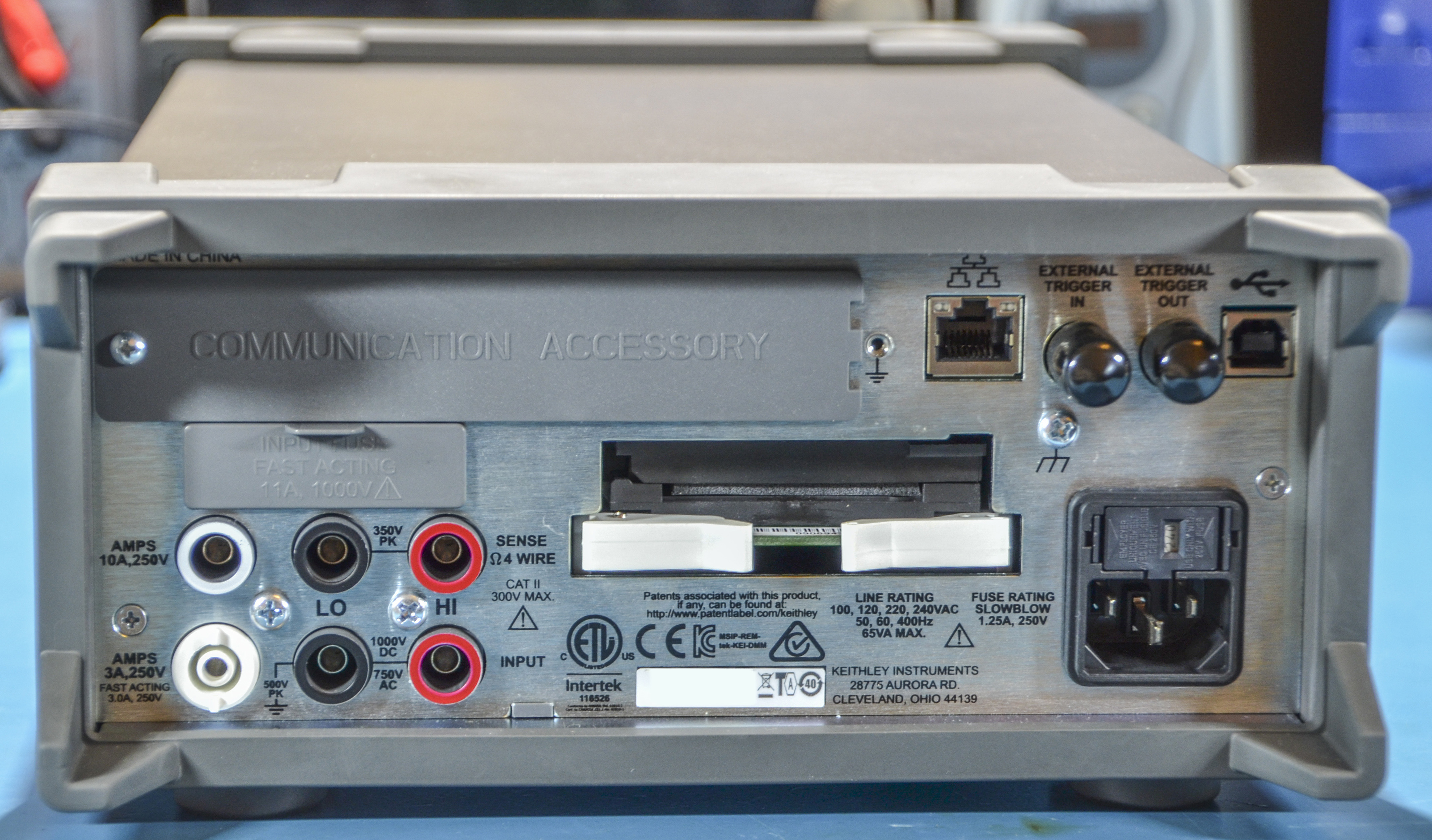
Image 2: Rear view on the unit
Rear side quite busy with connector and option ports. Communication option feature GPIB card. Smaller populated card in center is scanner option. Old scan cards like 2001-TCSCAN and 2000-SCAN are fully supported.
There is no hardware power switch for mains power, so meter is always have stand-by power present.
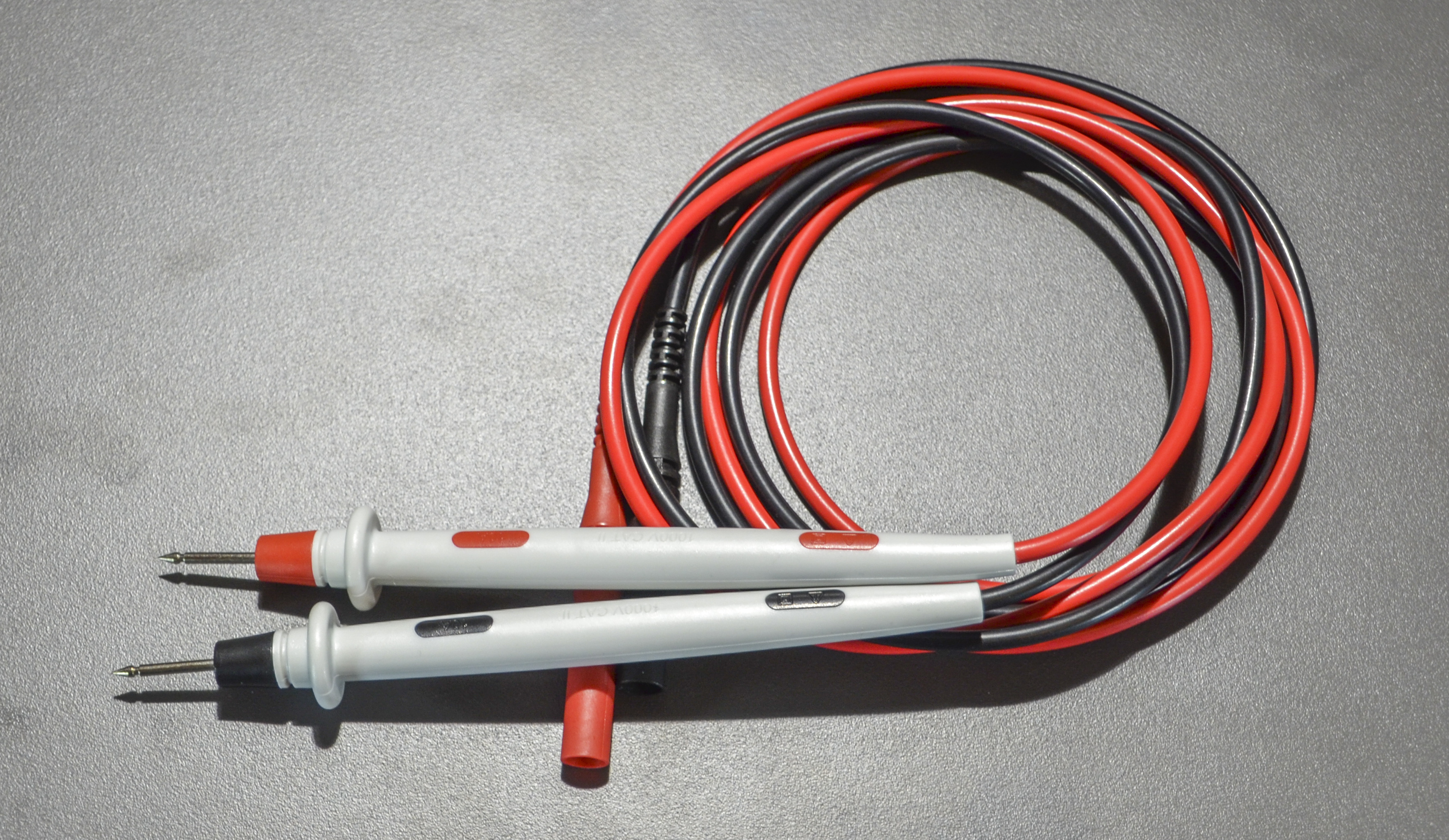
Image 3: Bundled probes, decent quality with shrouded banana ports
Probes are typical for benchtop meter.
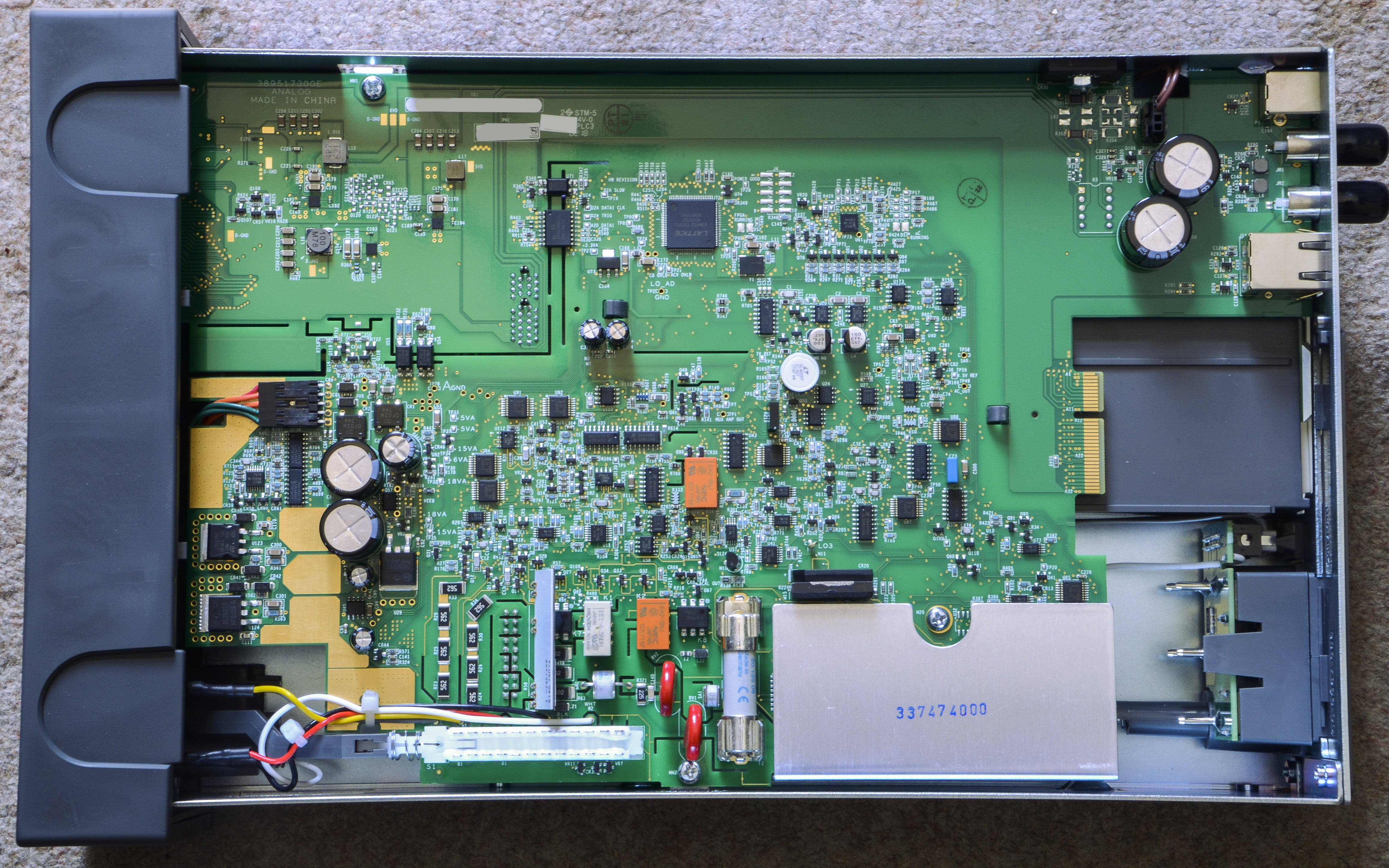
Image 4: Removed cover, top view
“We are in like Flynn”. Large mainboard with many slots and sections contain all the meter’s circuitry.

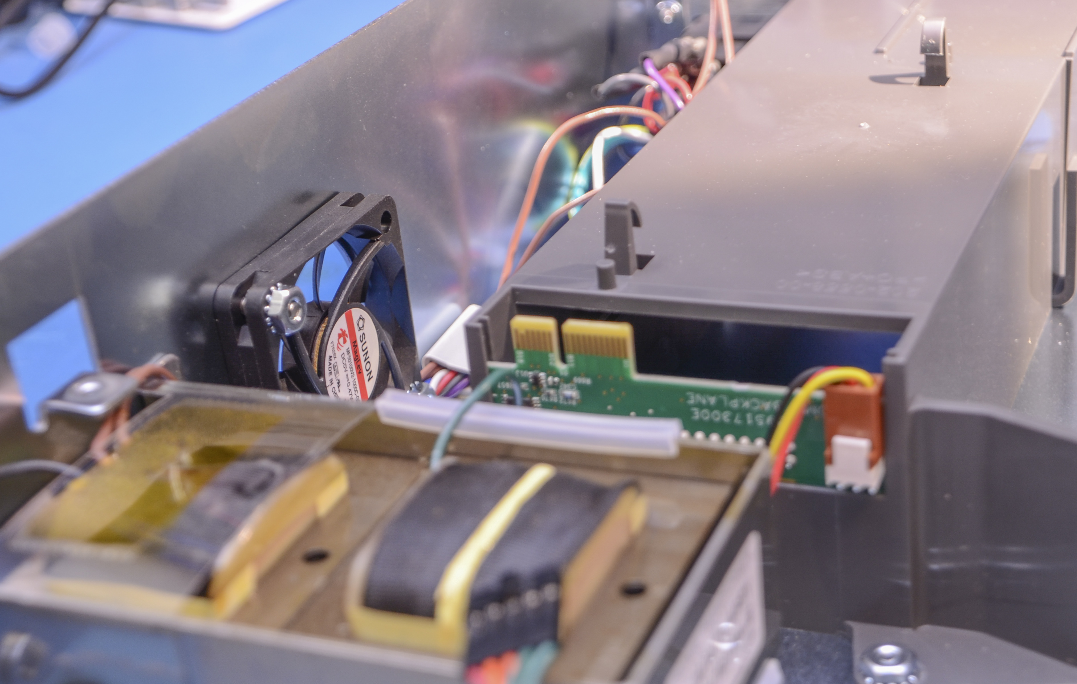
Image 5: Mainboard removed, mains transformer, option scanner card cage and wiring
Transformer is rigidly fixed to the chassis frame, which on early units caused some unwanted buzzing noise. Later units, according to Keithley, already addressed this.
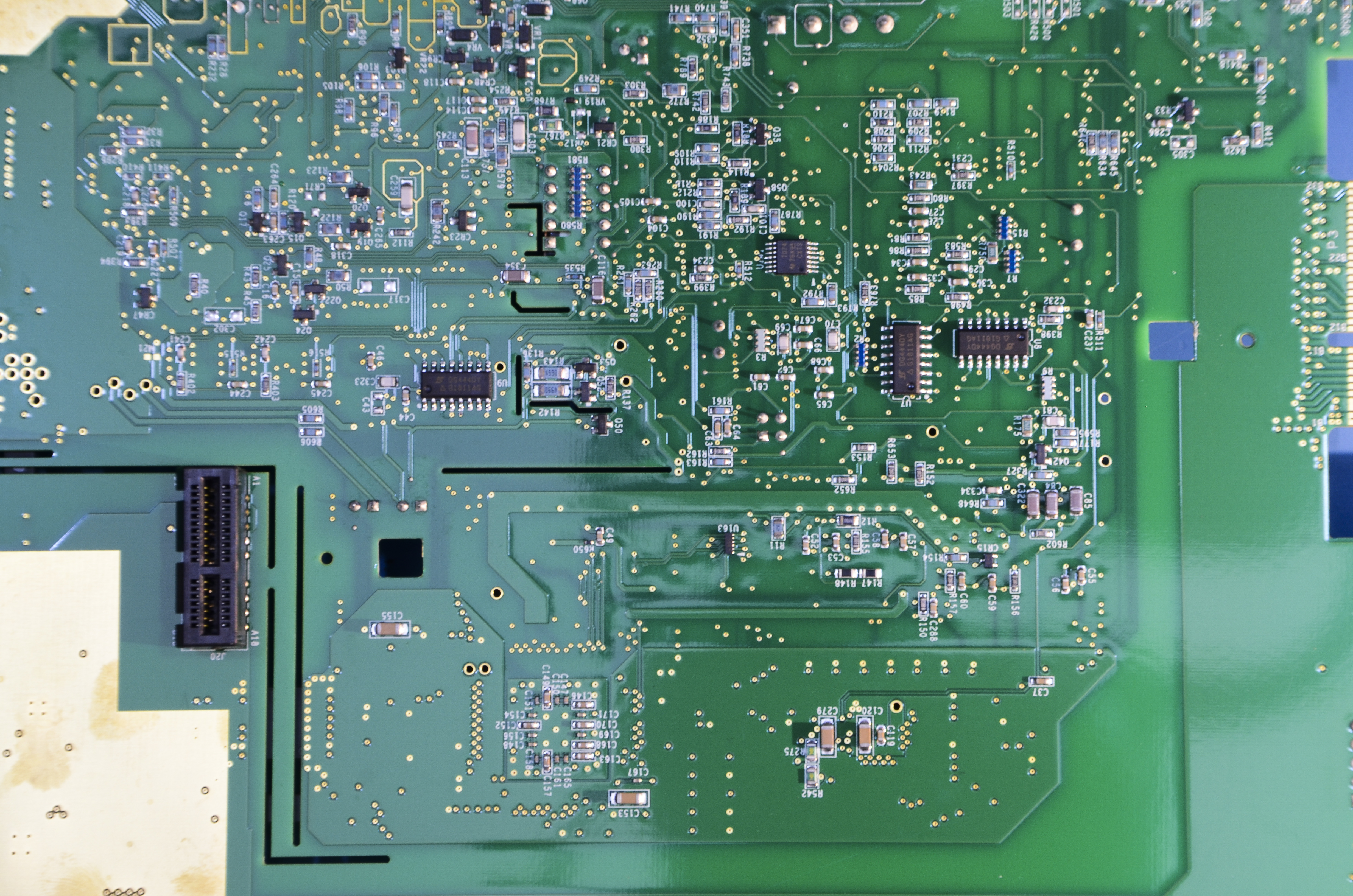
Image 6: Bottom side of the mainboard
Not much components on this side, mostly passives with few chips.
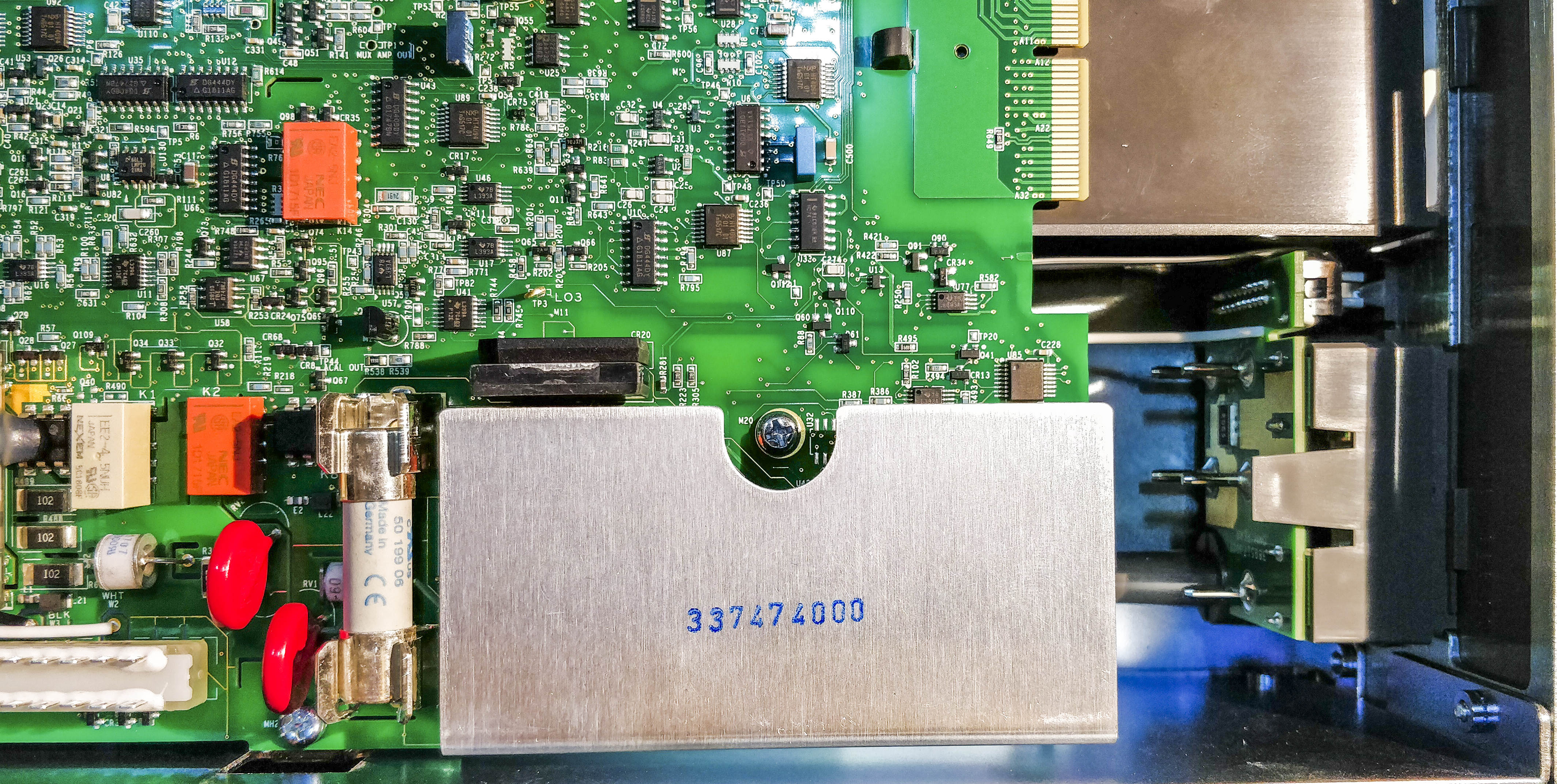
Image 7: Input section
Input DCI function is protected by large fuse in holder. Mechanical front/rear switch also visible on the corner, with rest of input protection parts.

Image 8: Rear side of the front panel assembly
Front panel PCBA busy with BGA chips, as big fancy LCD need lot of juice to process and refresh the images quickly. Two Freescale/NXP chips in center are MPC5125 32-bit microprocessors with e300c4 Power Architecture® core, display interface, 10/100 MAC, USB and all usual interfaces.

Image 9: Another angle
Not sure why need two processors. Perhaps once is handling display/front panel functionality only, while the second actually runs meter firmware/functions? Lattice LFE5U is ECP5 FPGA, featuring 24K LUT elements and about a megabit of onboard memory. It supports lot of high-speed interfaces, and may be the one responsible of driving LVDS LCD.
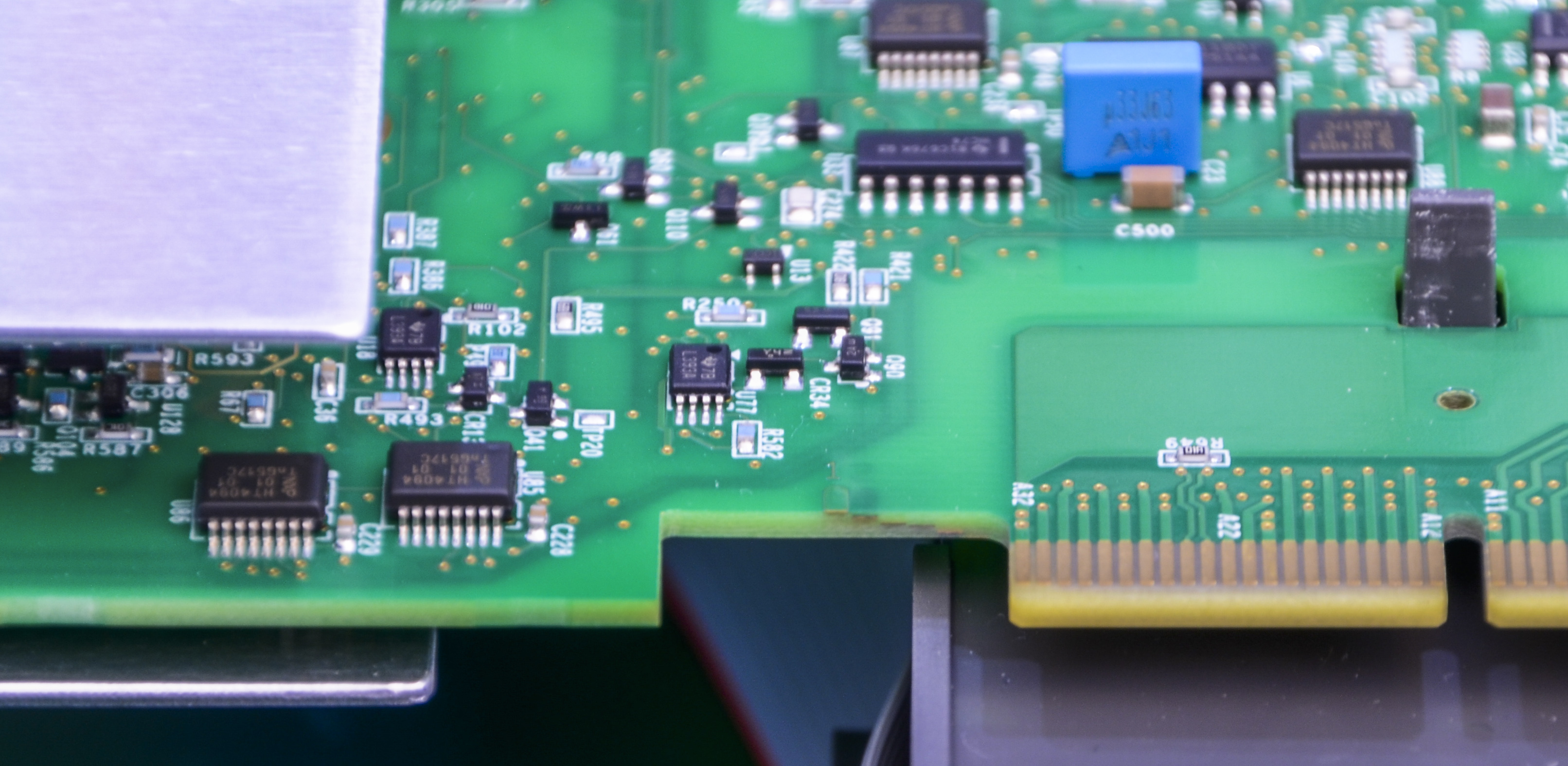
Image 10: Mainboard layer count
Mainboard PCB is designed with six layer metal interconnect. This is clear, thanks to edge PCBA layer marker.
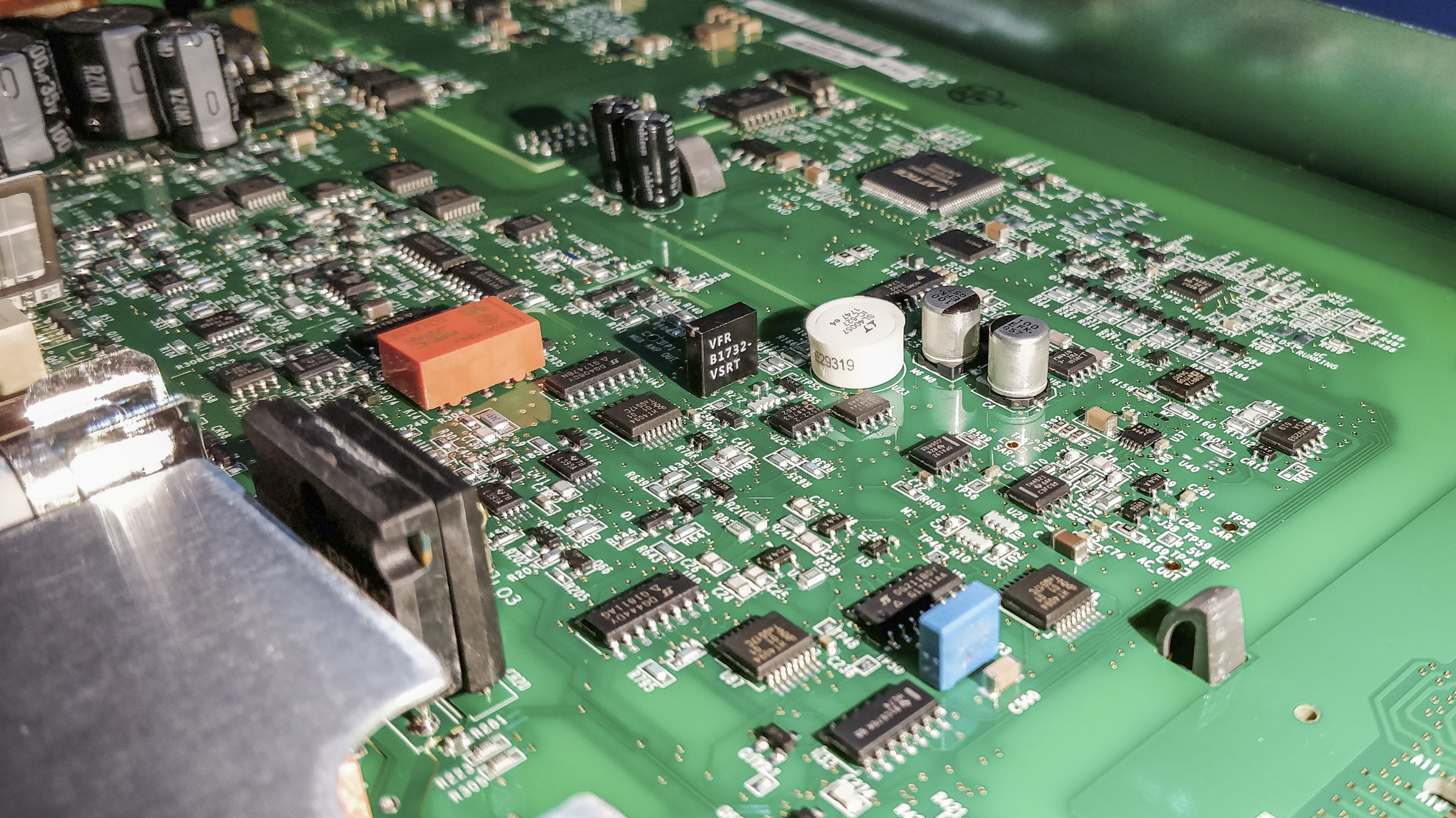
Image 11: Selected LM399AH voltage reference with Keithley marking on top
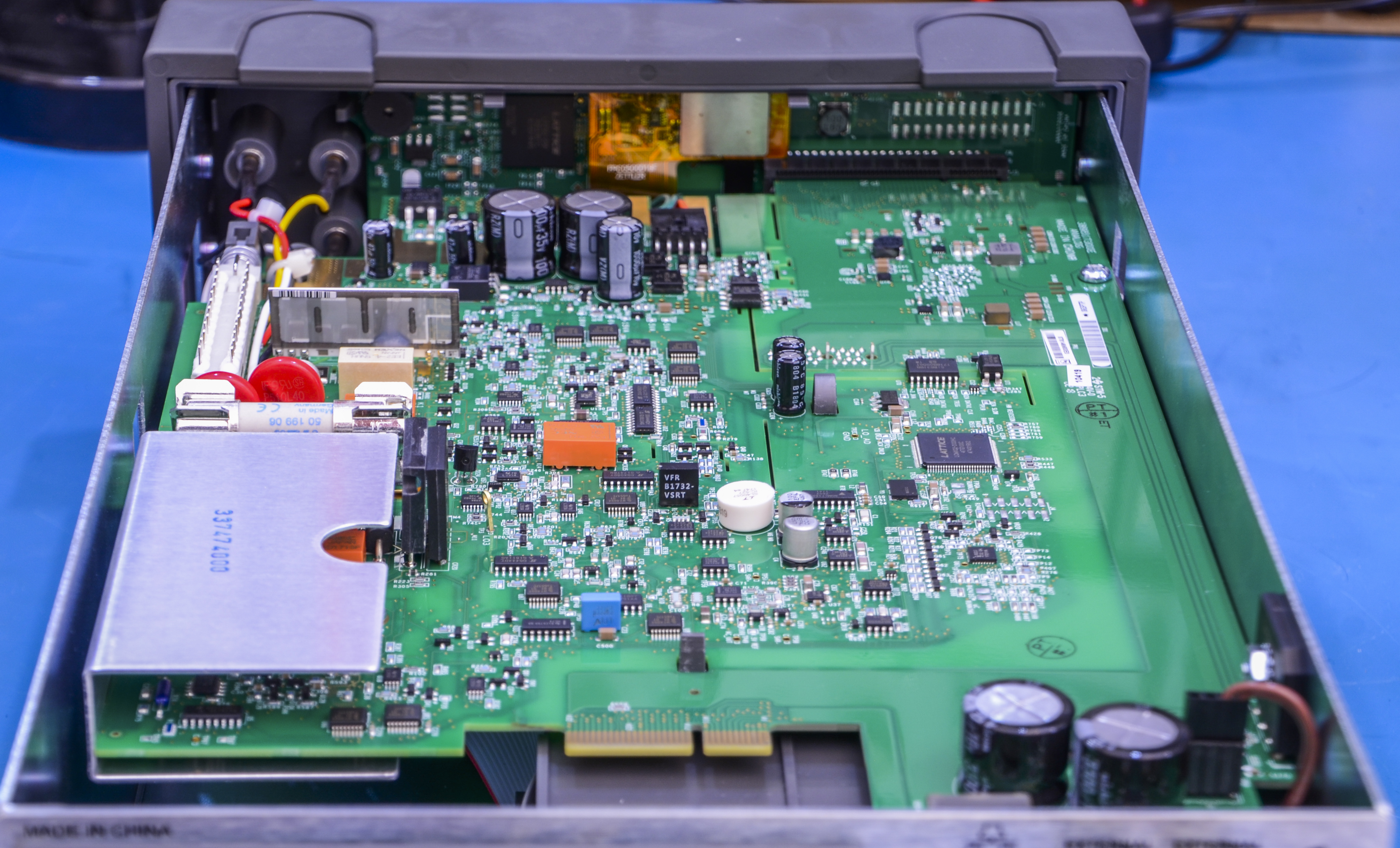
Image 12: Angle from the rear
Laser-trimmed hermetic film resistor visible on the left side. That is high-voltage divider for DCV/ACV ranges. Very common in Fluke meters and calibrators.
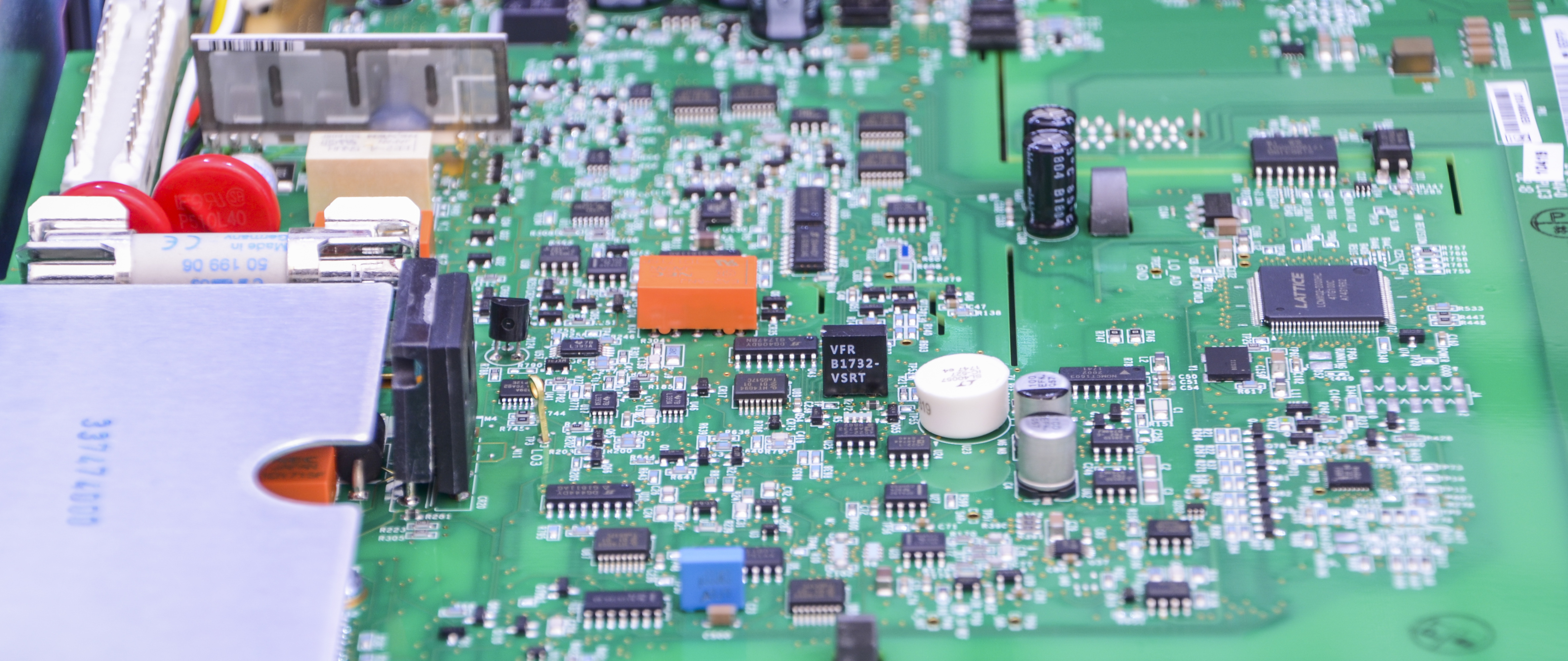
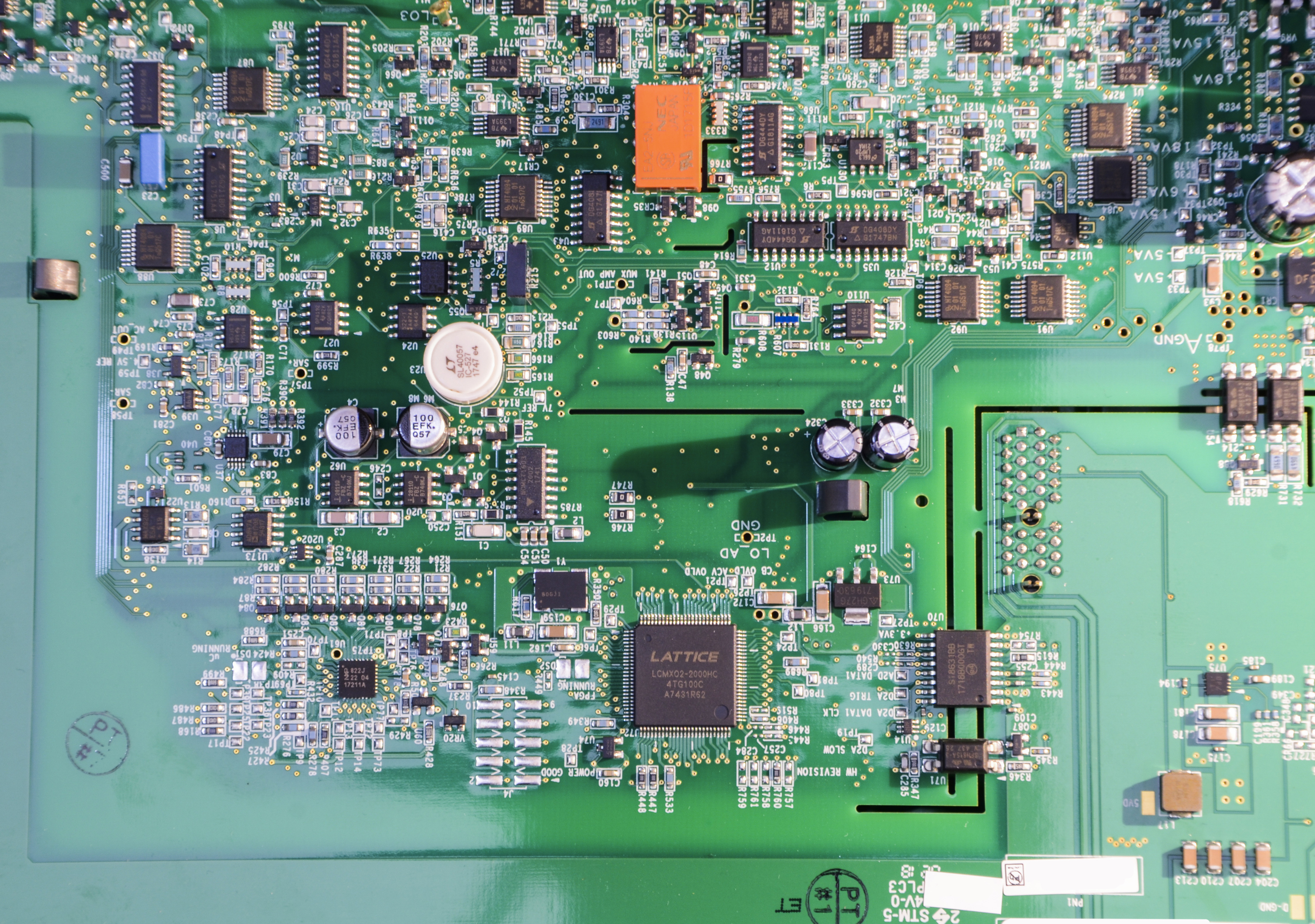
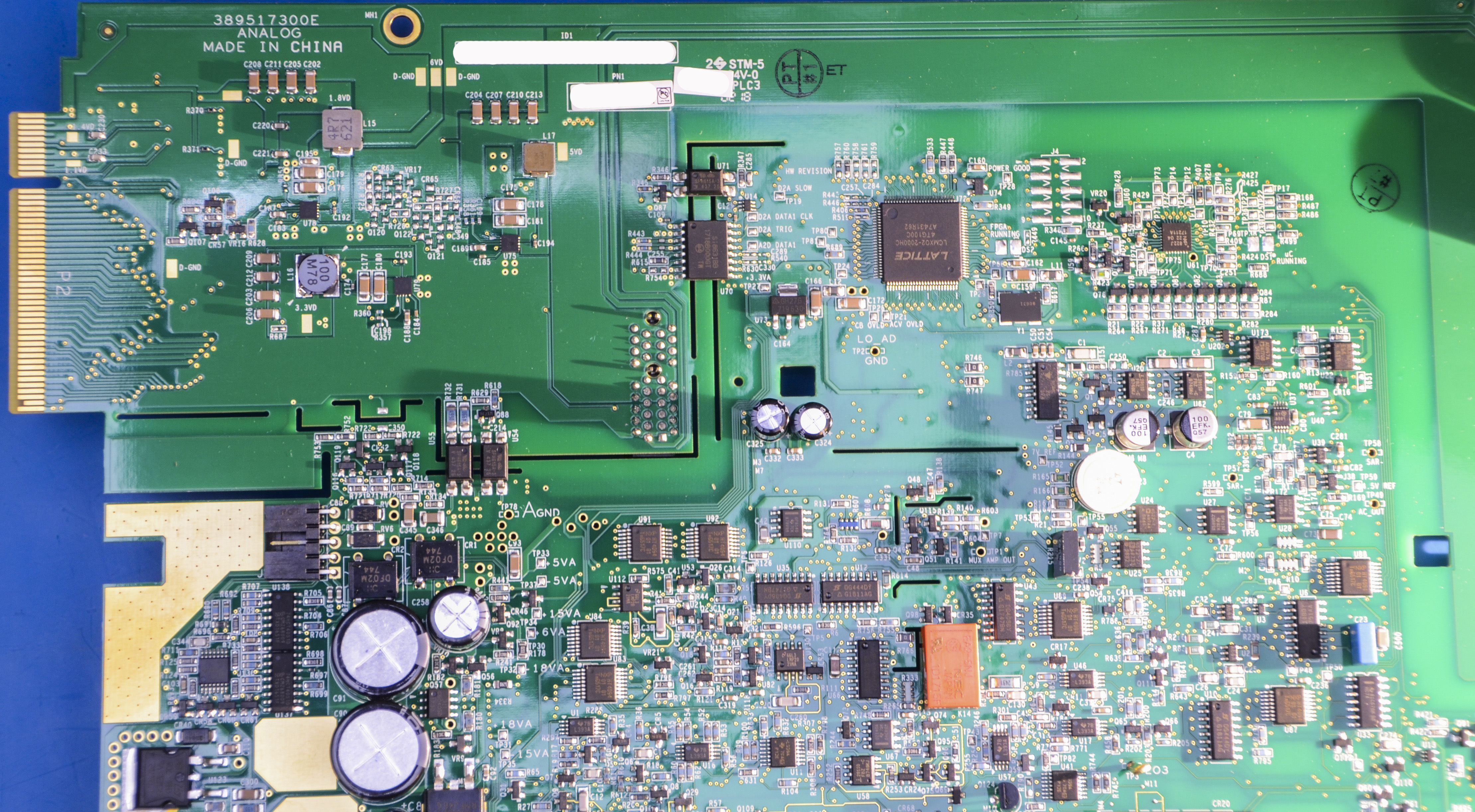
Image 13-15: Isolated sections
Si8631 and few opto’s take care of the insulation between outguard and inguard sides. Typical design for benchtop DMM, as these meters need to have front-end floating.
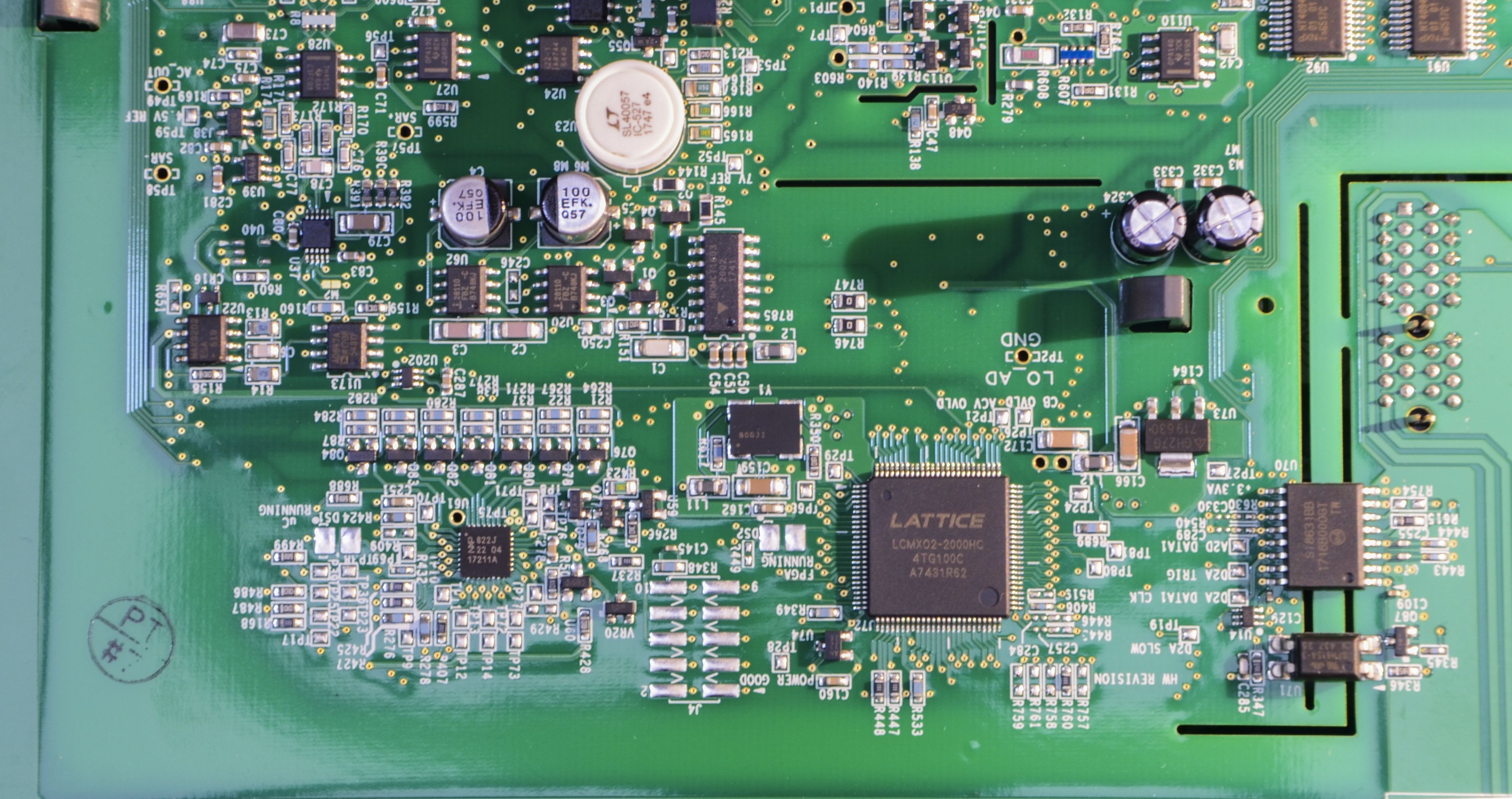
Image 16: Board
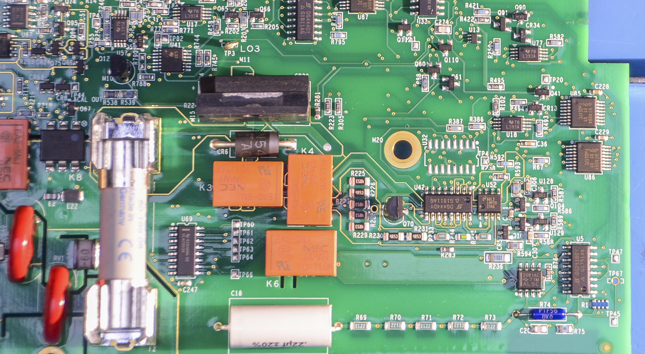
Image 17: Board
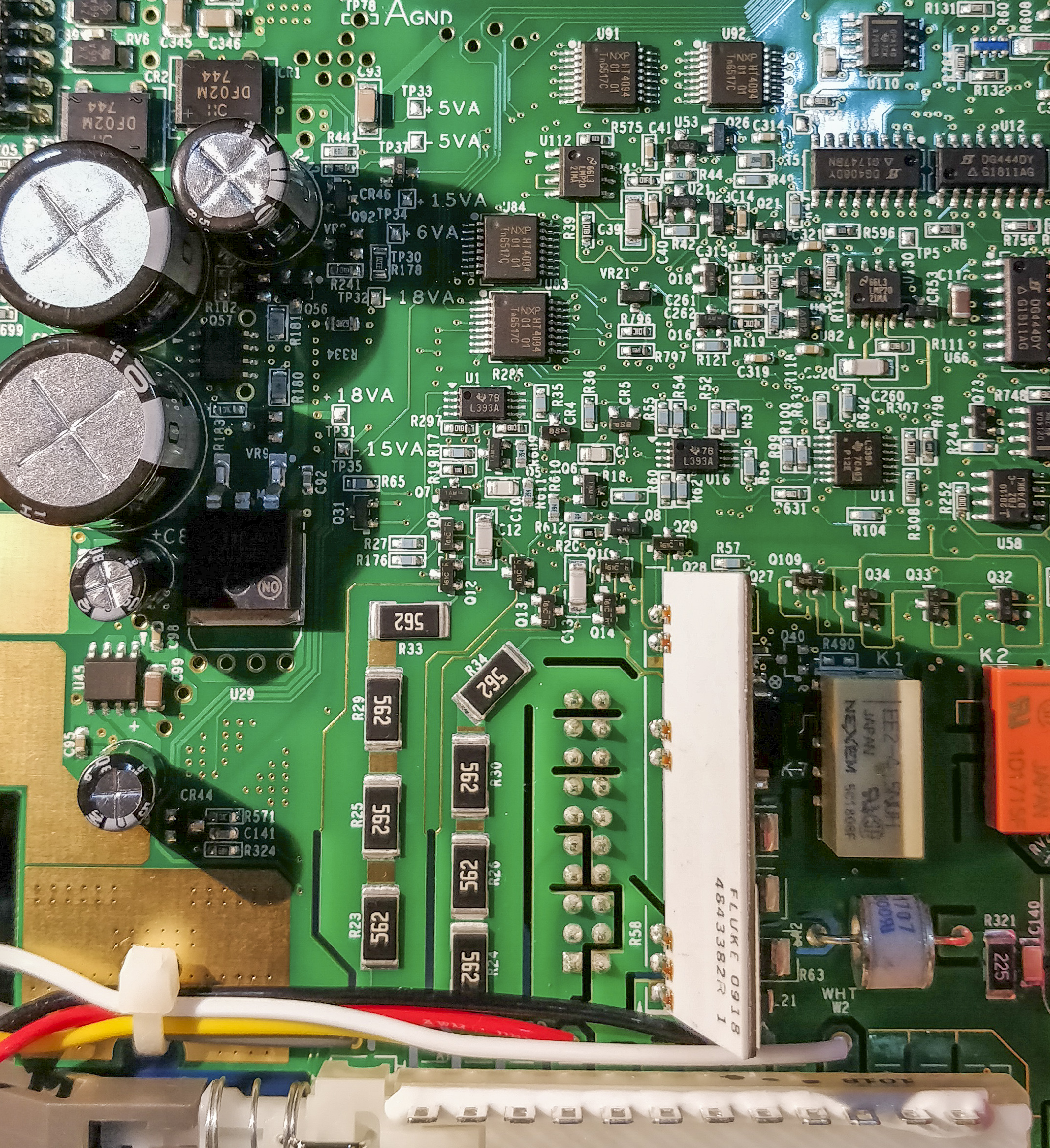

Image 18-19: Board


Image 20-21: Board
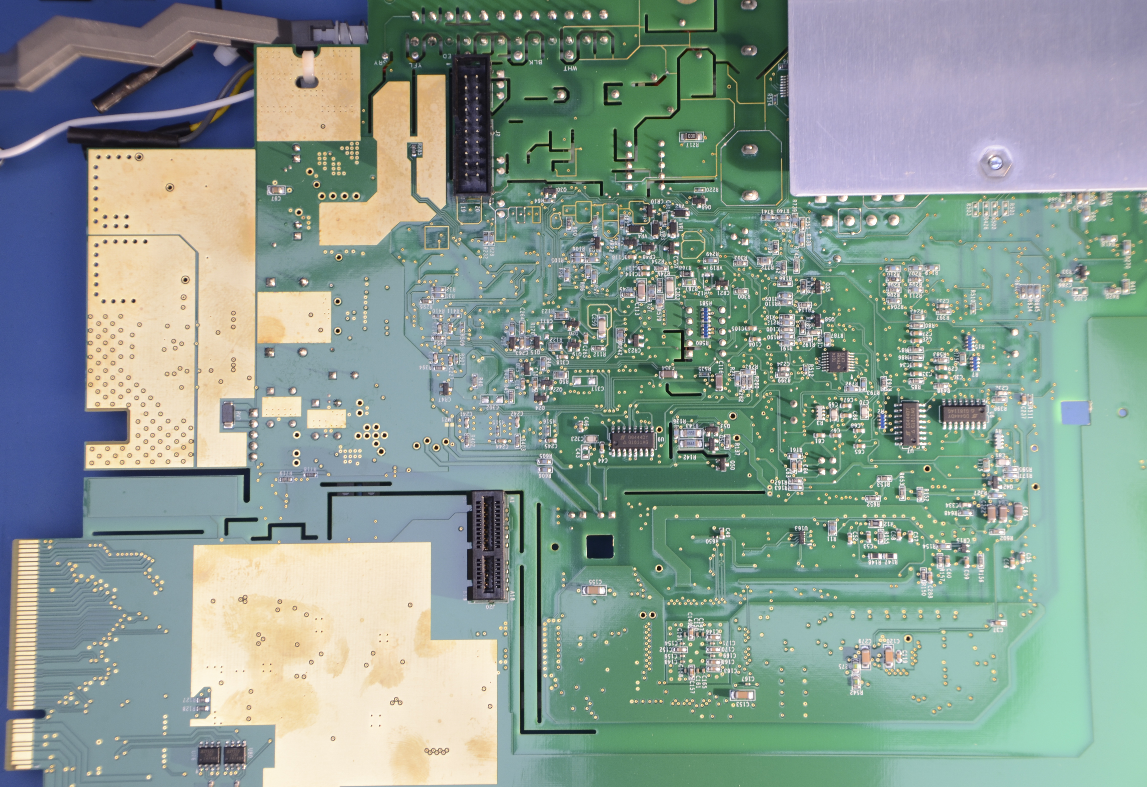
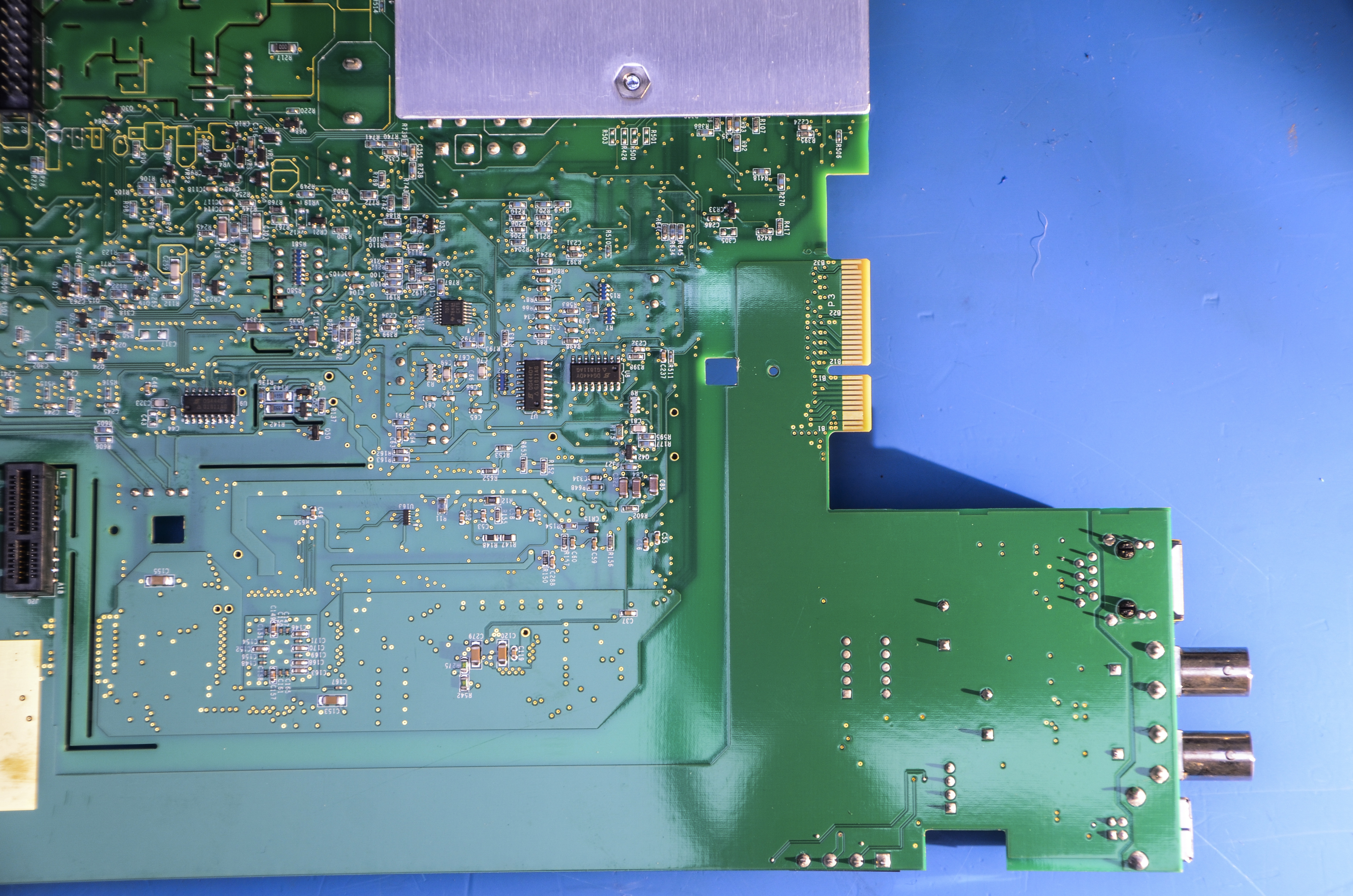
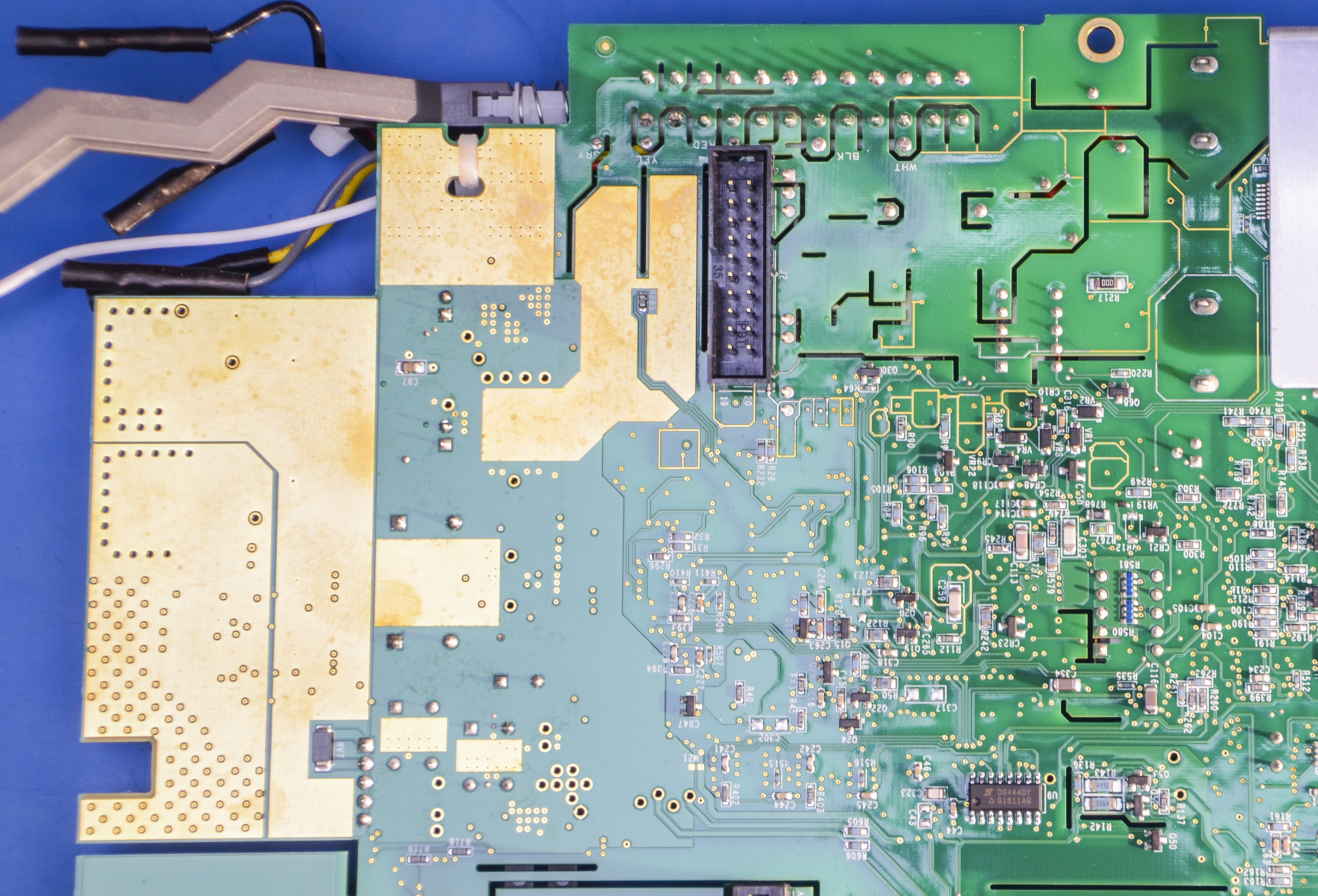

Image 22-25: Board
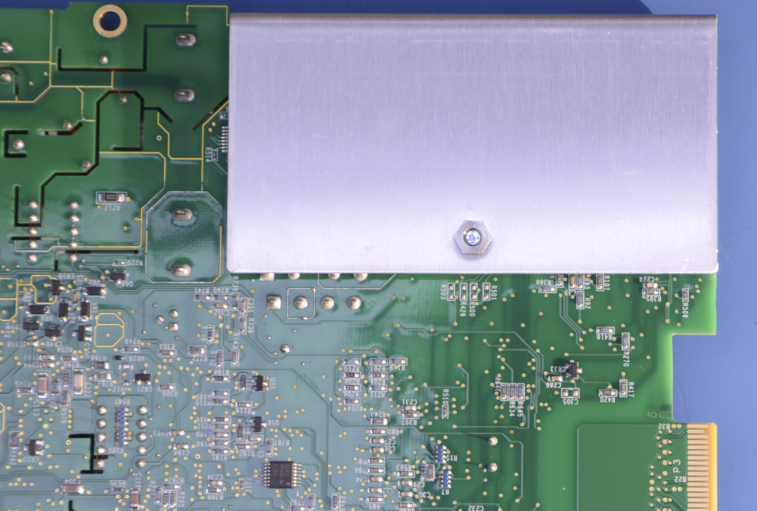
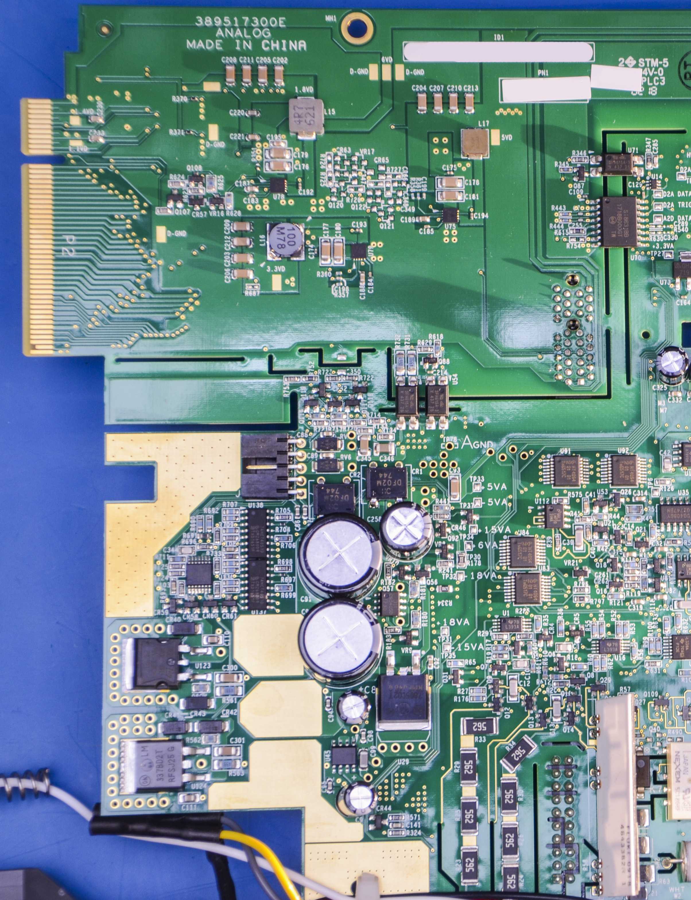
Image 26-27: Board
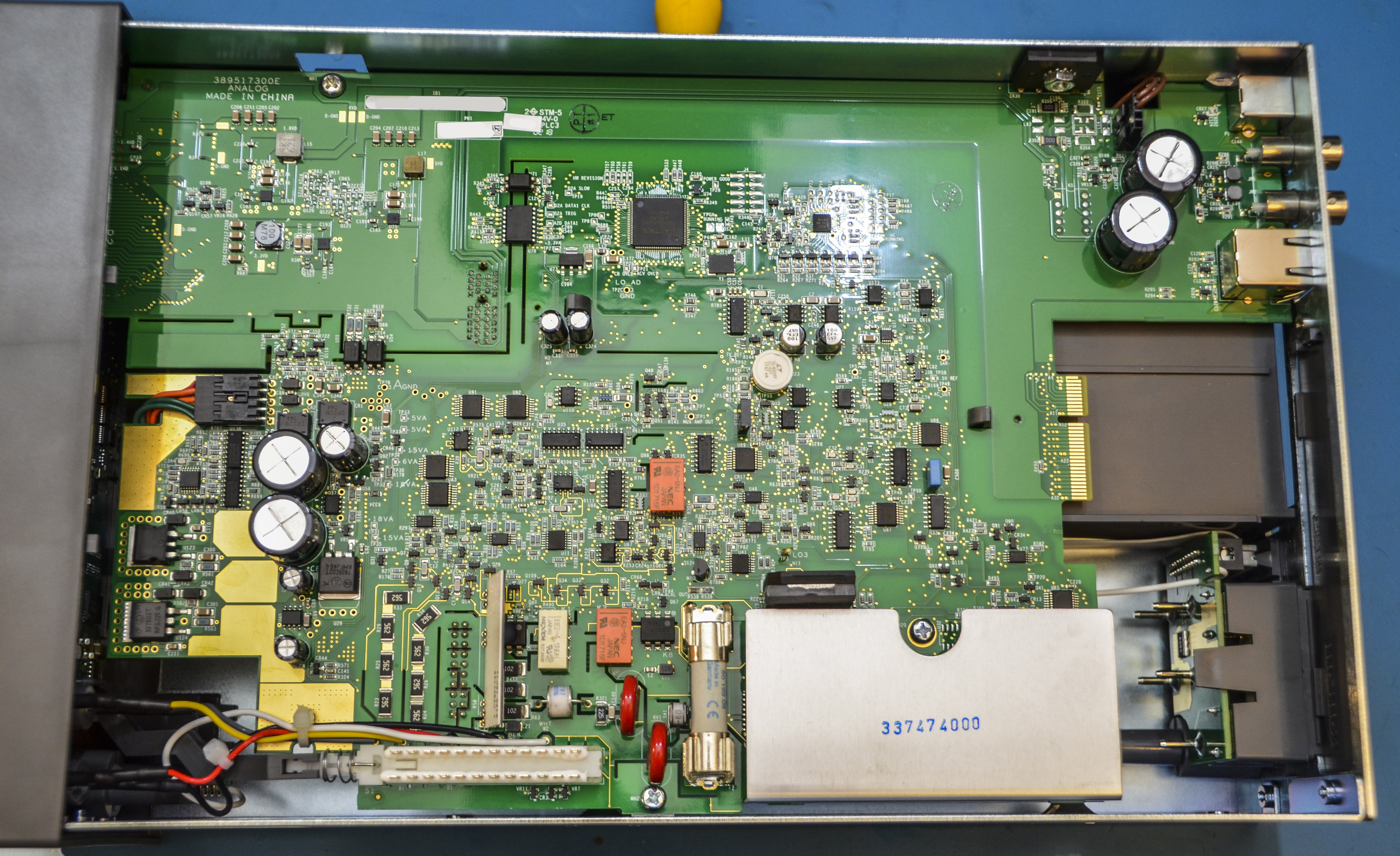
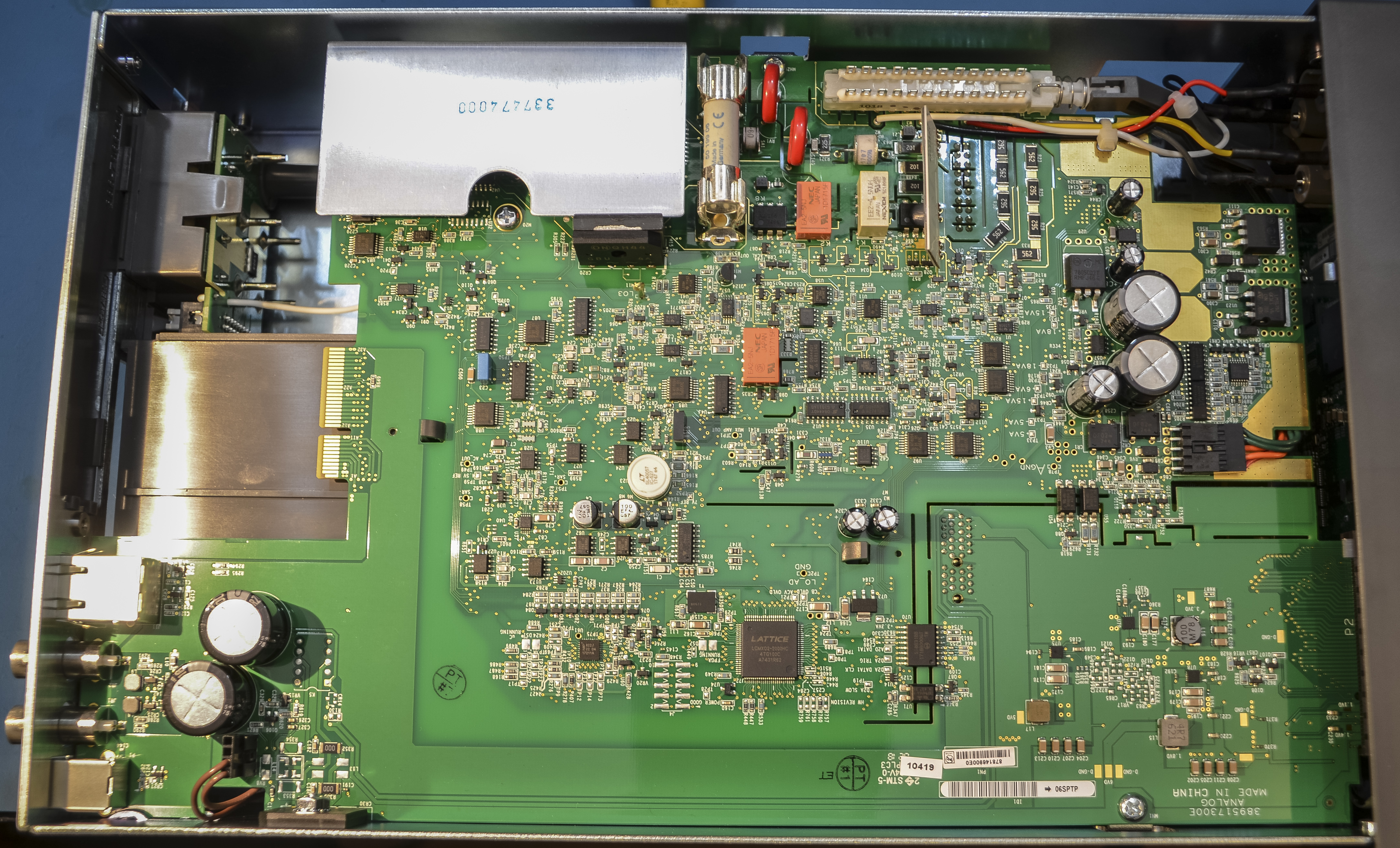
Image 28-29: Board
![]()
Image 30-31: View on the little fan
Small 40 × 40 mm DC fan located next to transformer. Hopefully this fan does not get too noisy after few years of use.

Image 32: Transformer assembly frame
Image 33-34: Second device next to transformer
Transformer shares same assembly block with inductor. Inductor is used for PFC correction for the mains input.
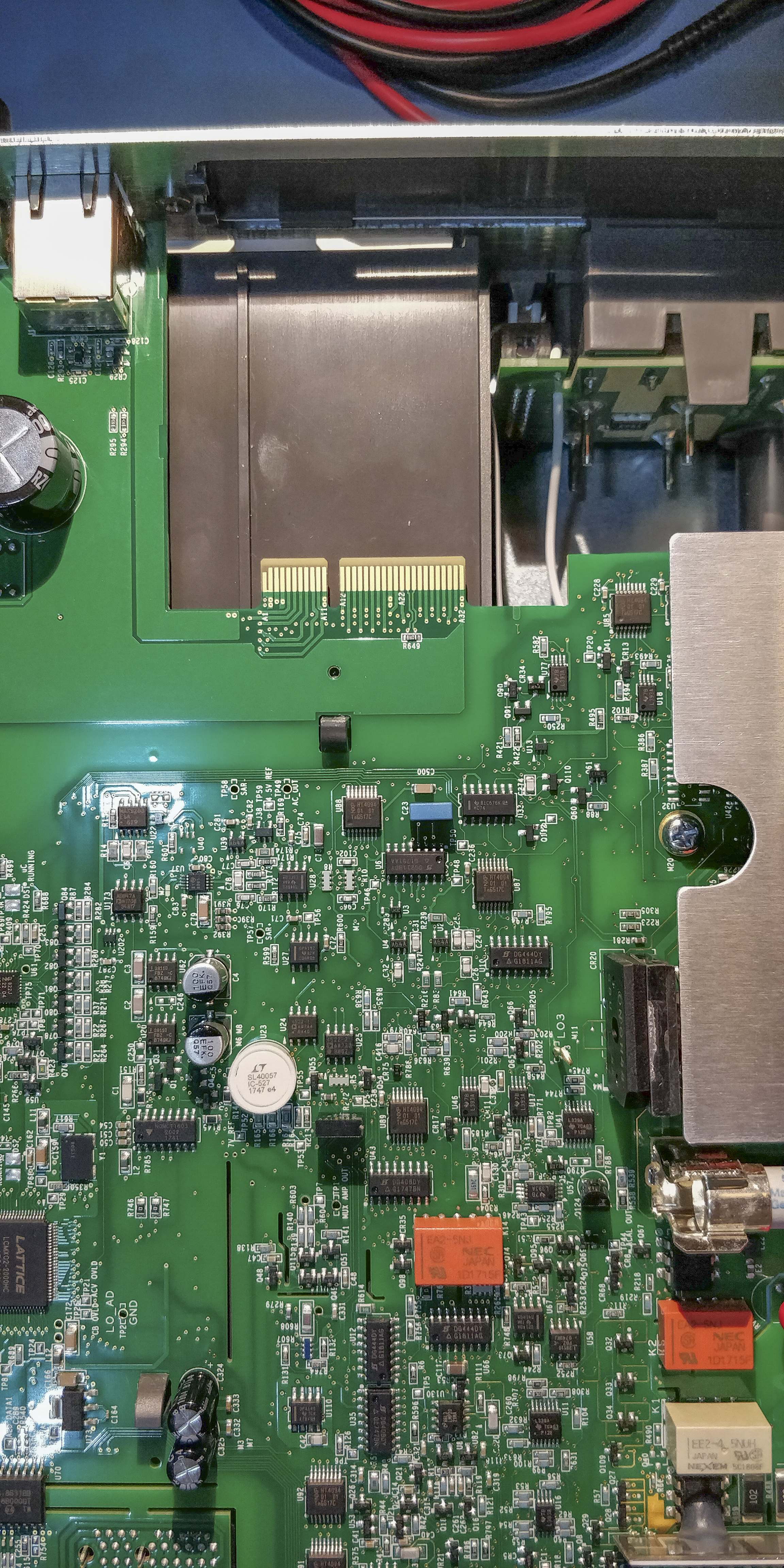
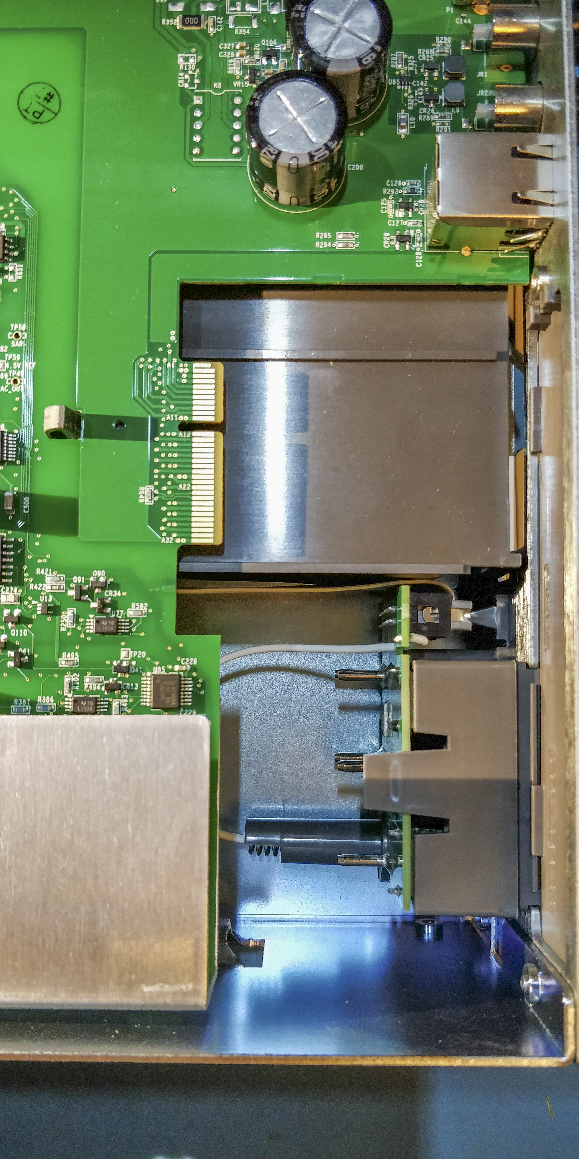
Image 35-36: Board
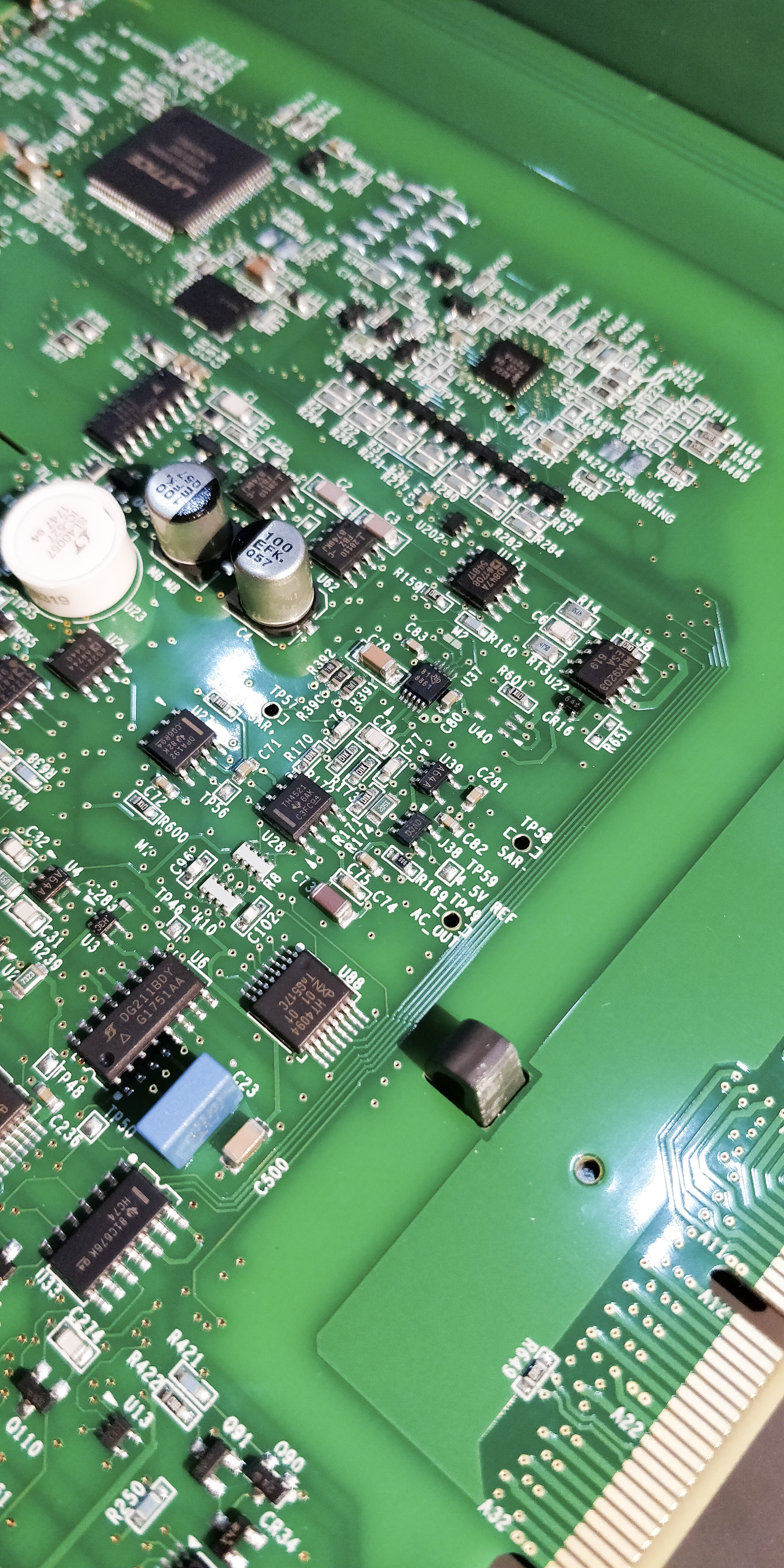
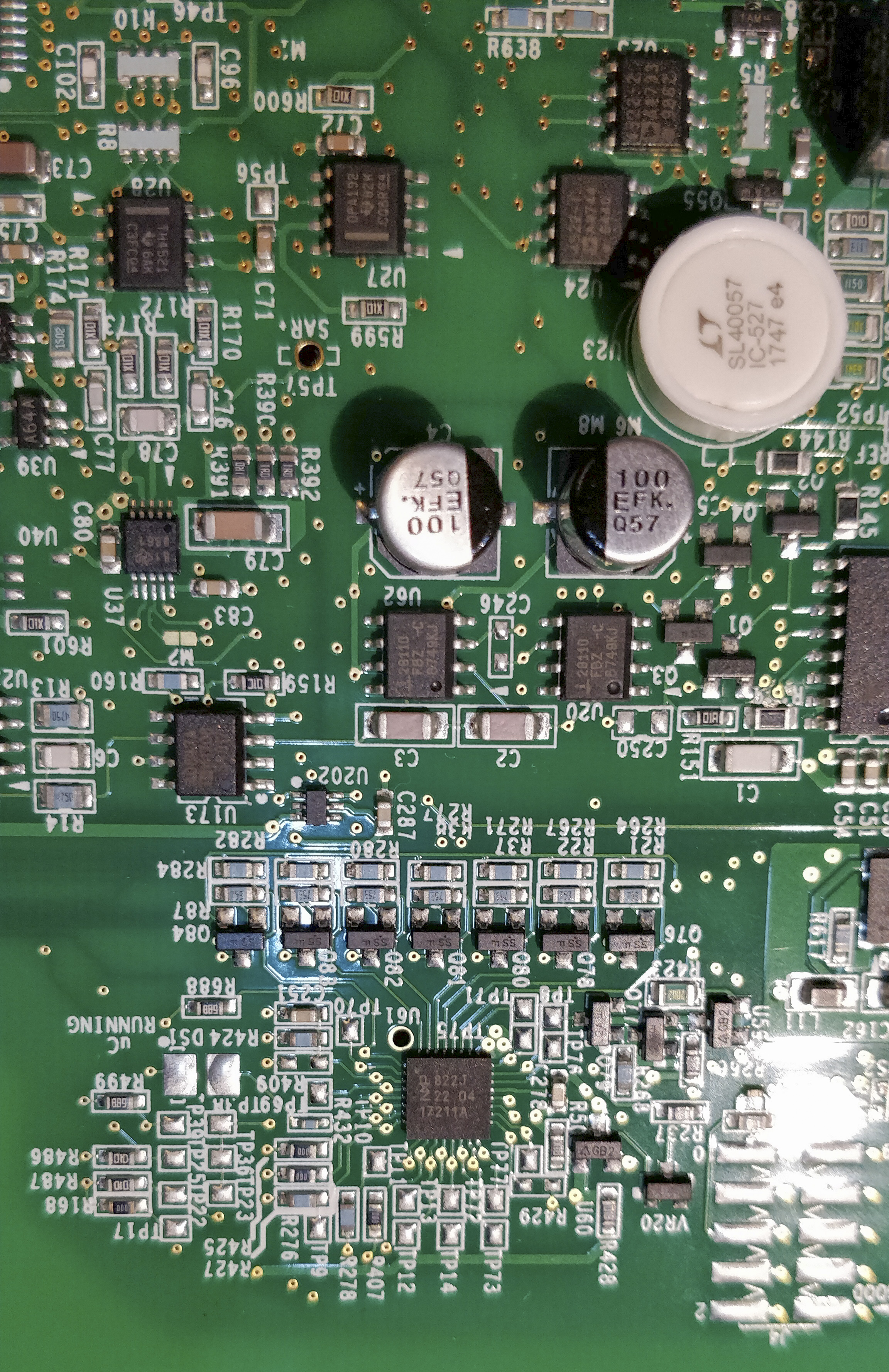
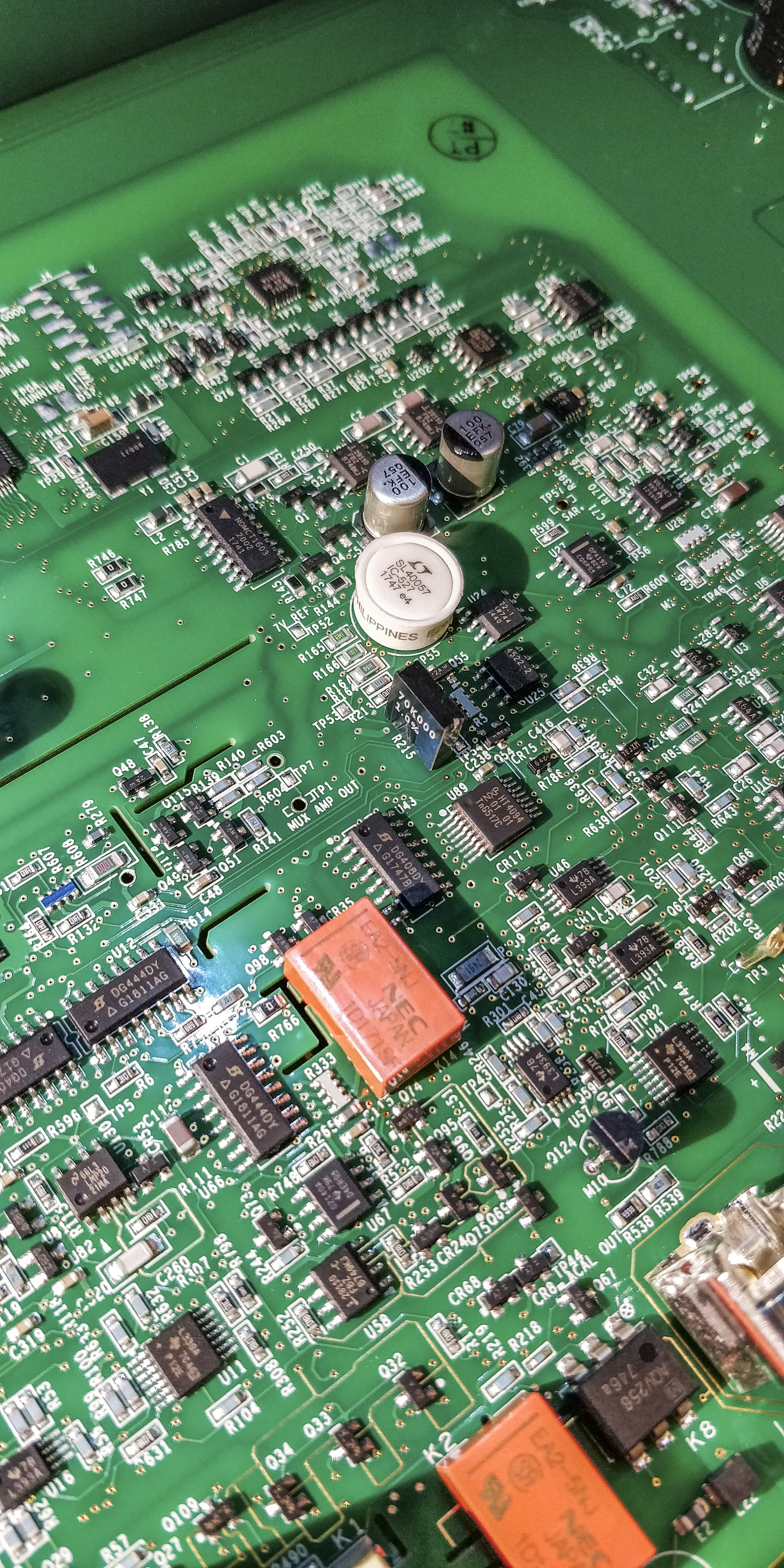
Image 37-39: Board
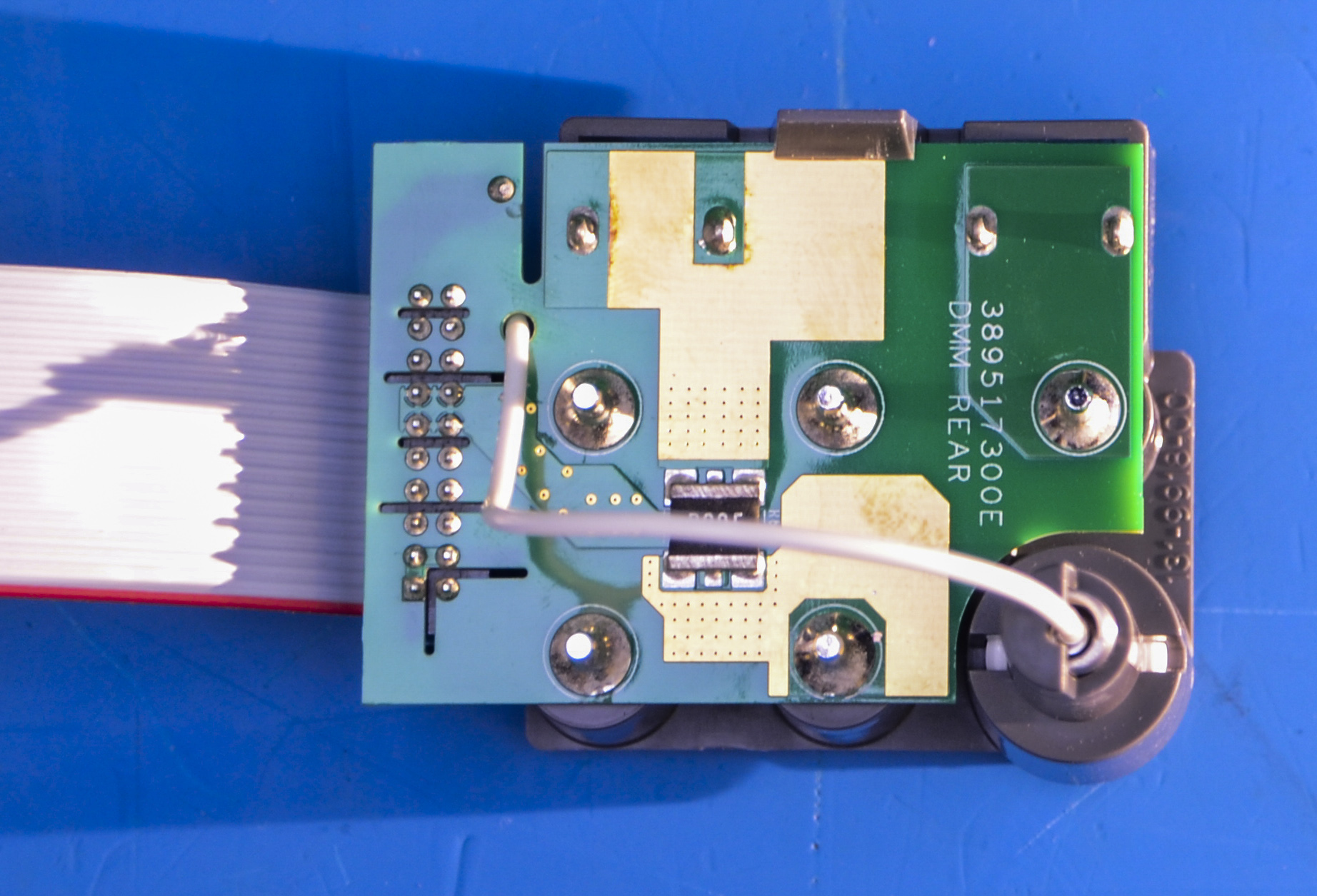
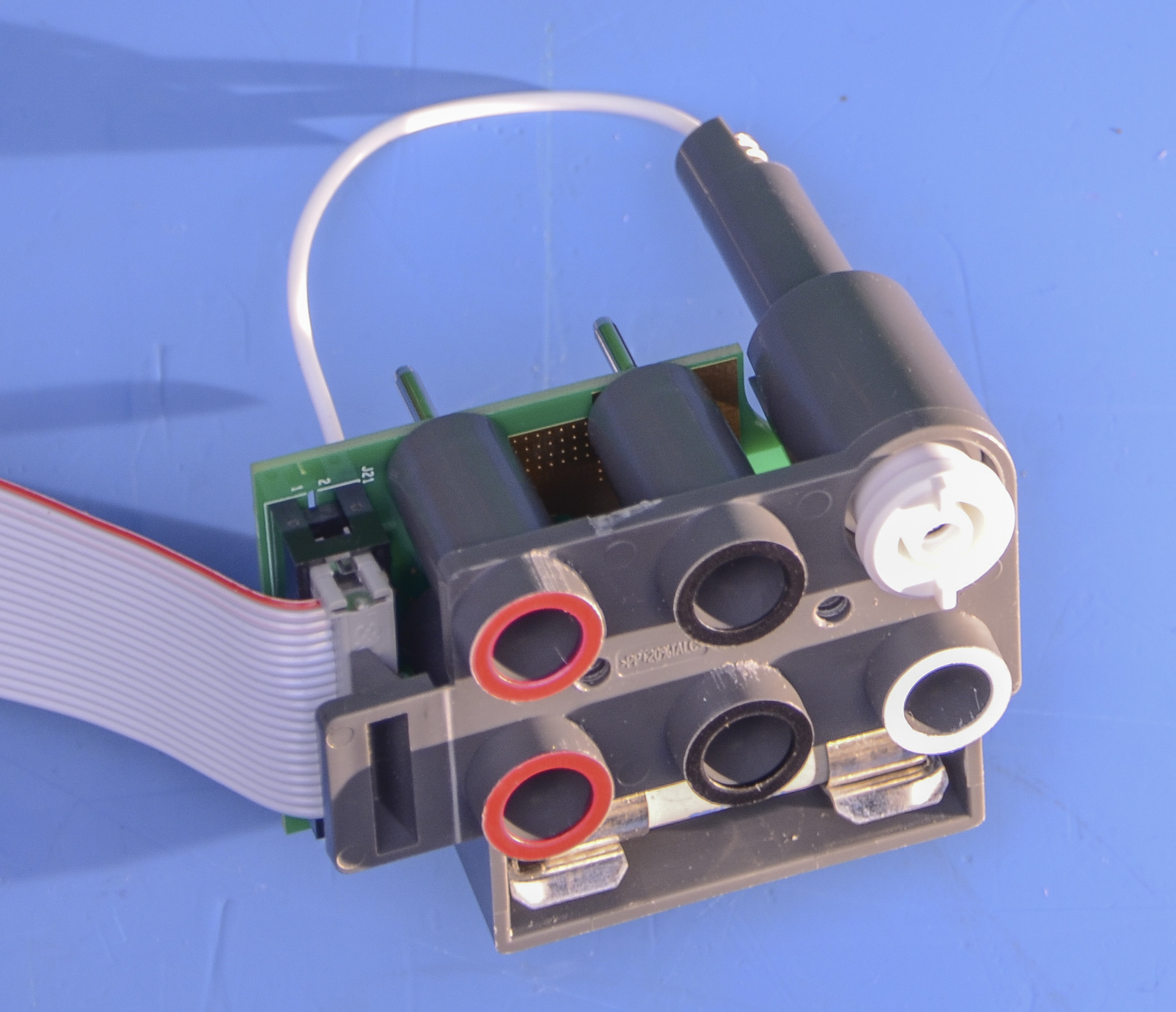
Image 40-41: Rear terminal jack
Rear terminal jack with IDC cable? That’s not really what we expected to see in 6½-digit meter with 10 µA current range.


Image 42-43: Board
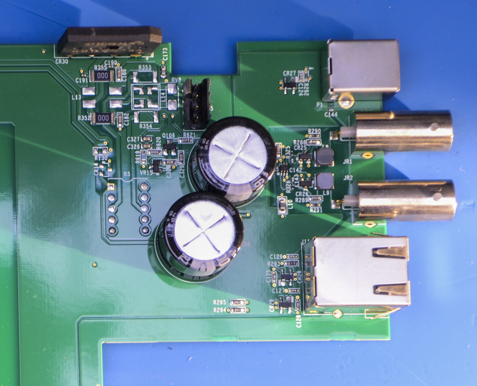
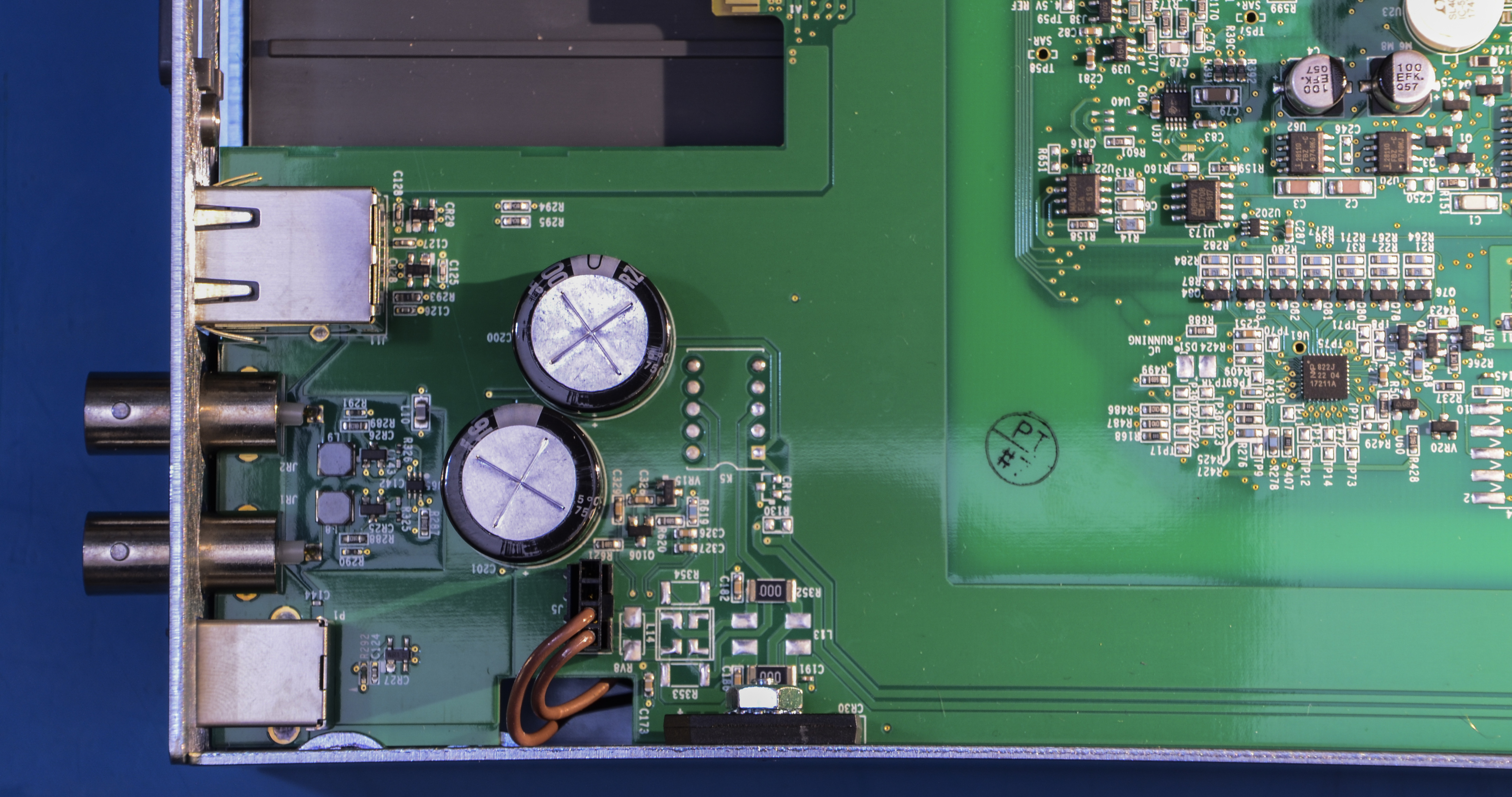
Image 44-45: RJ45 MagJack and interface ports
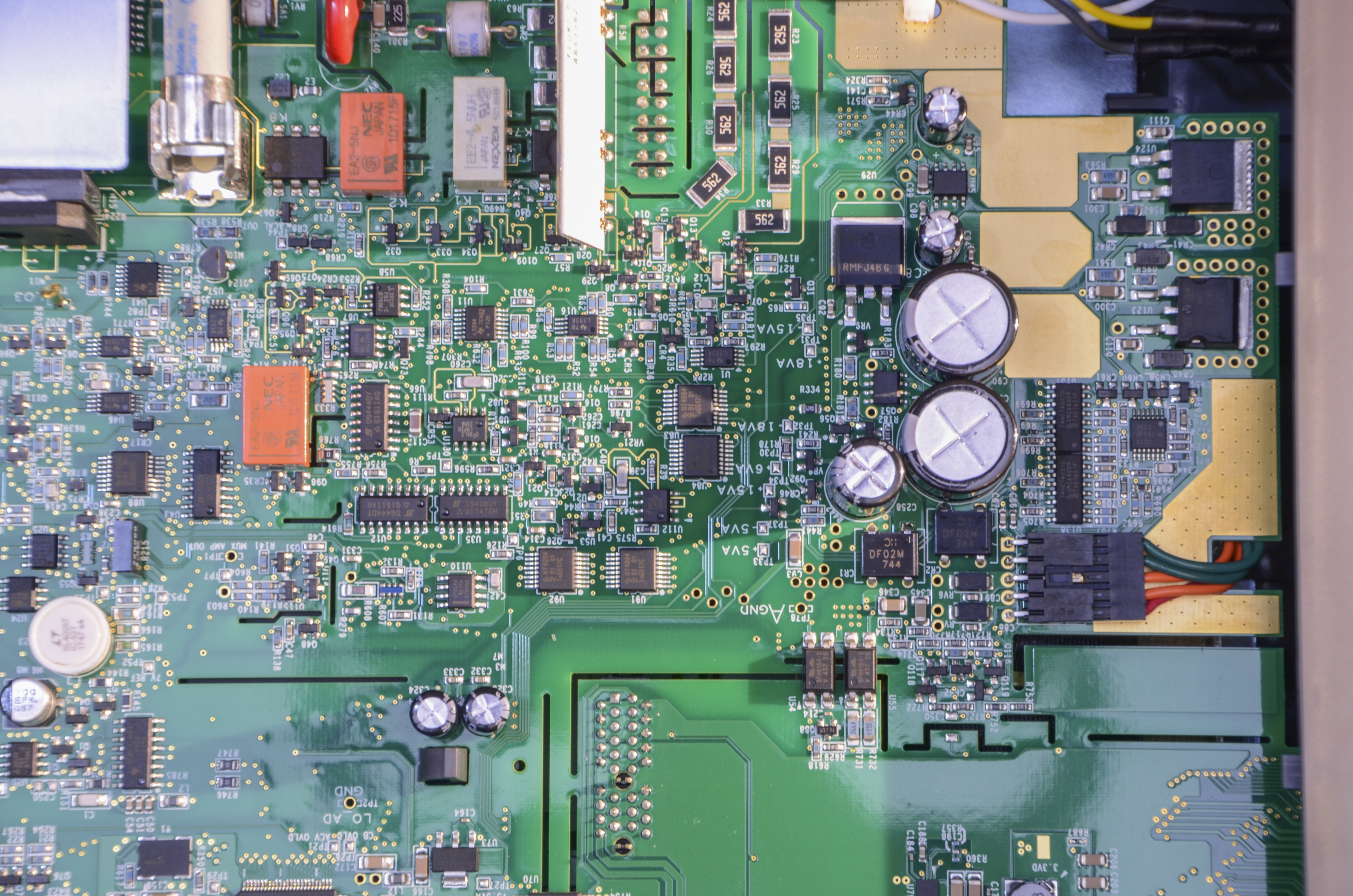
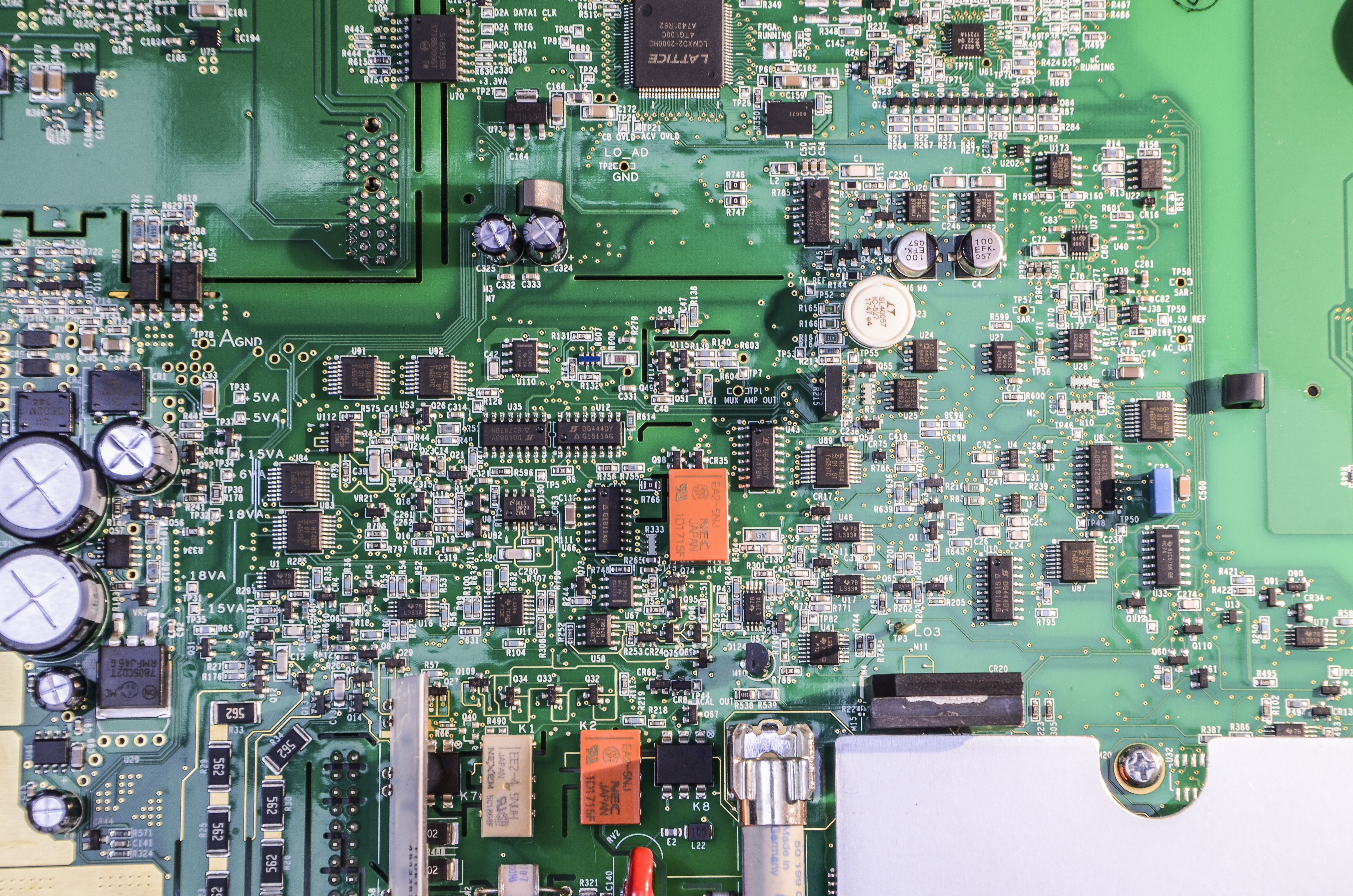
Image 46-47: Few last internal photos
Transformer hum
Early DMM6500 units had quite pronounced transformer 50/60Hz audible hum. This was reported as solved for later production units.
One of our readers, Vit S. suggested a mitigation for affected units humming. His unit came set to 220V (for EU geo). EU spec is 230V, ±10%. It was suggested that transformer might be saturated from bit overvoltage, as we generally have overvoltaged mains a bit. He measured mains and it read at 245 VAC, so switching input on DMM6500 to 240V reduced audible humming.
Performance results
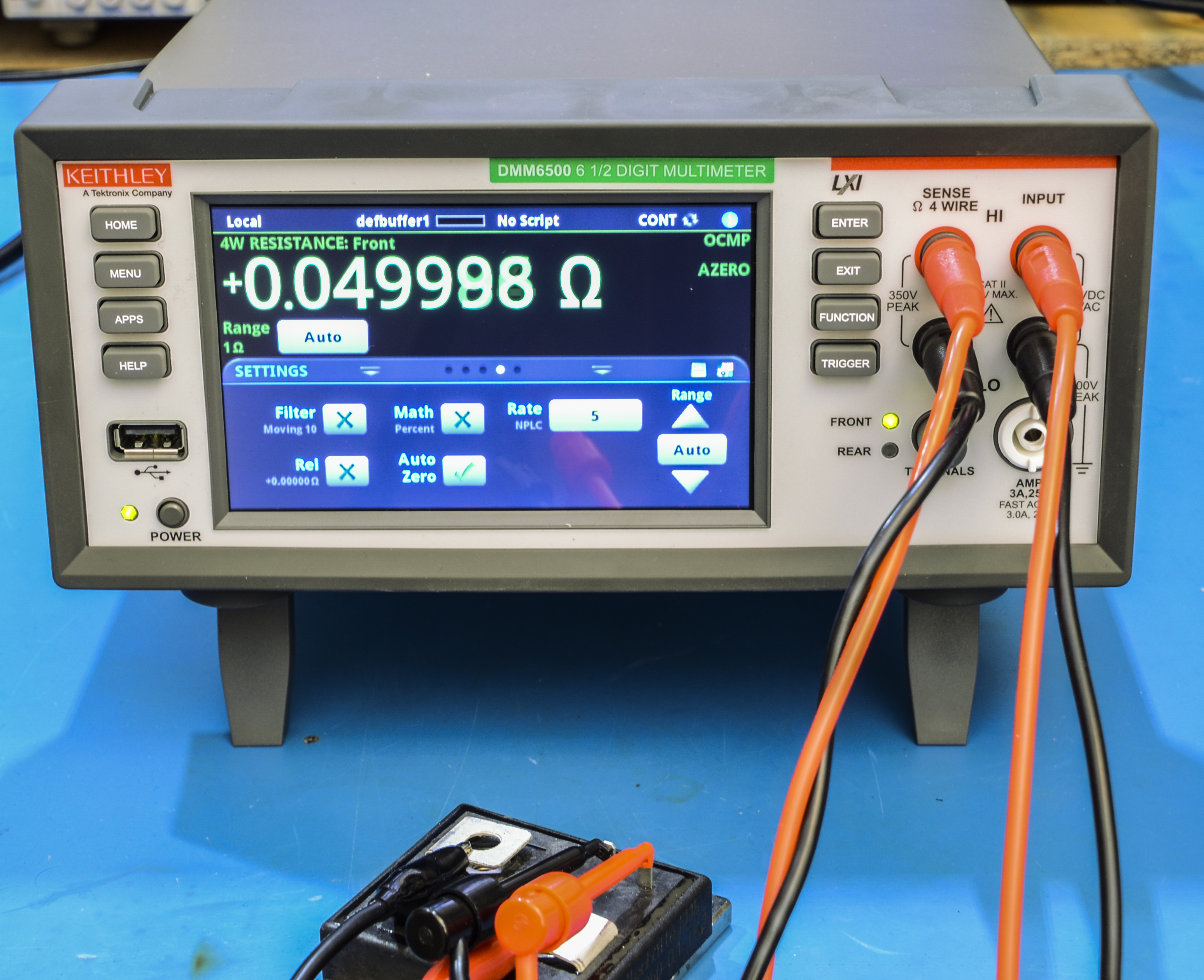
Image 48: DMM measuring 50 mΩ shunt in 4-wire mode
Update from a reader on his DMM6500
Robert S. sent us some more photos of Keithley DMM6500 inner workings. Thank you for contribution.
This DMM was purchased new in March 2021 and have few differences inside:
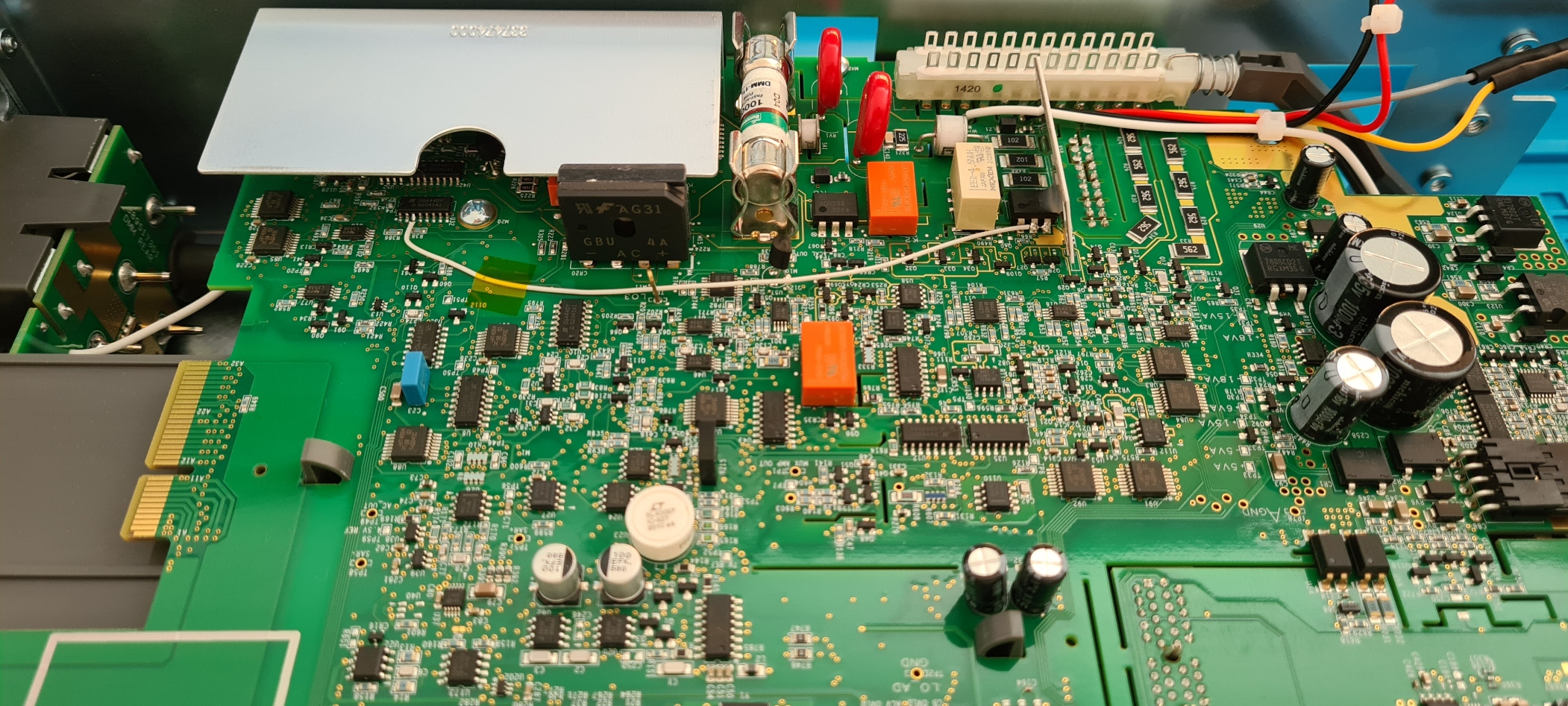
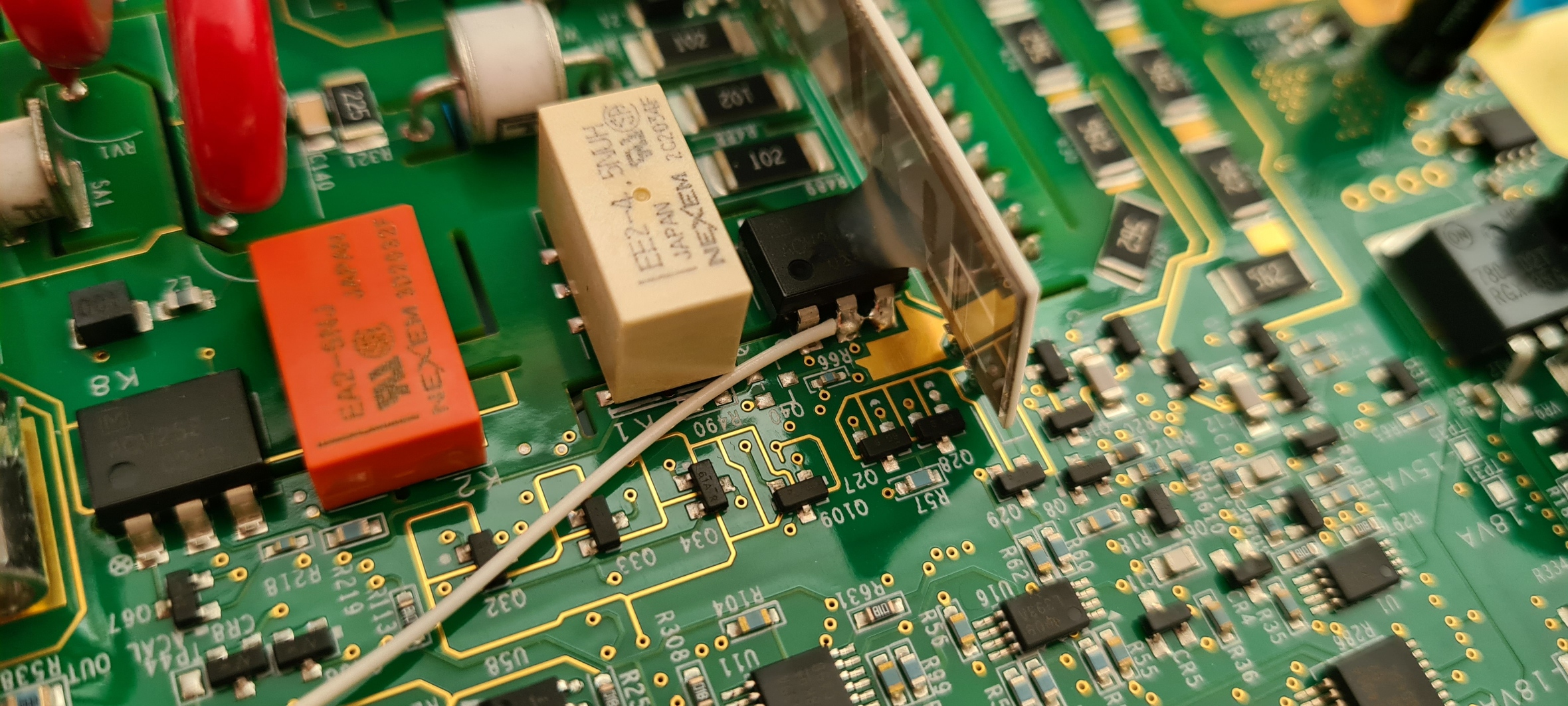
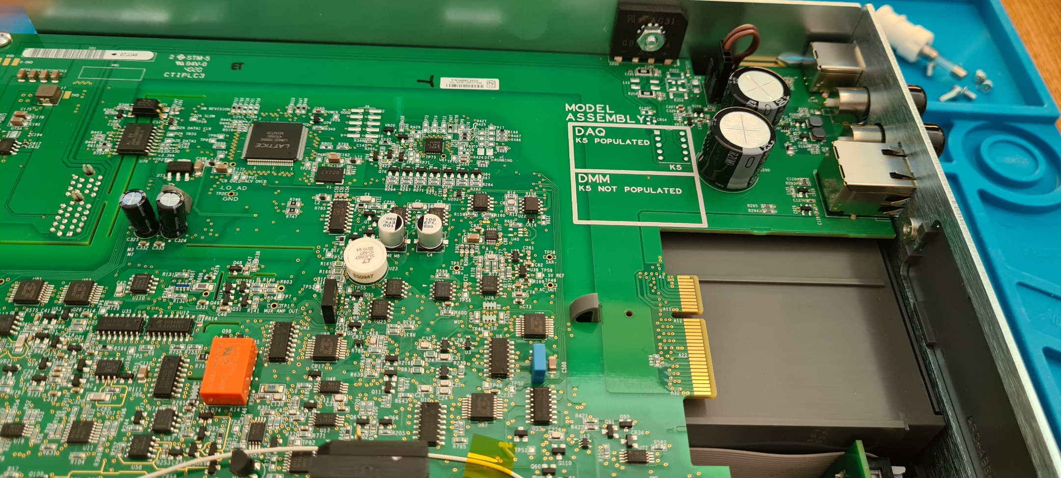
There is a mod wire soldered from U32.3 to K7.2-3. Also Keithley put a silkscreen labels on board to specify when K5 will be populated or not, depends on option model.

This DMM was assembled around 46th week of 2020. LM399A reference with special partnumber for Keithley was cooked around 10th week of 2020.
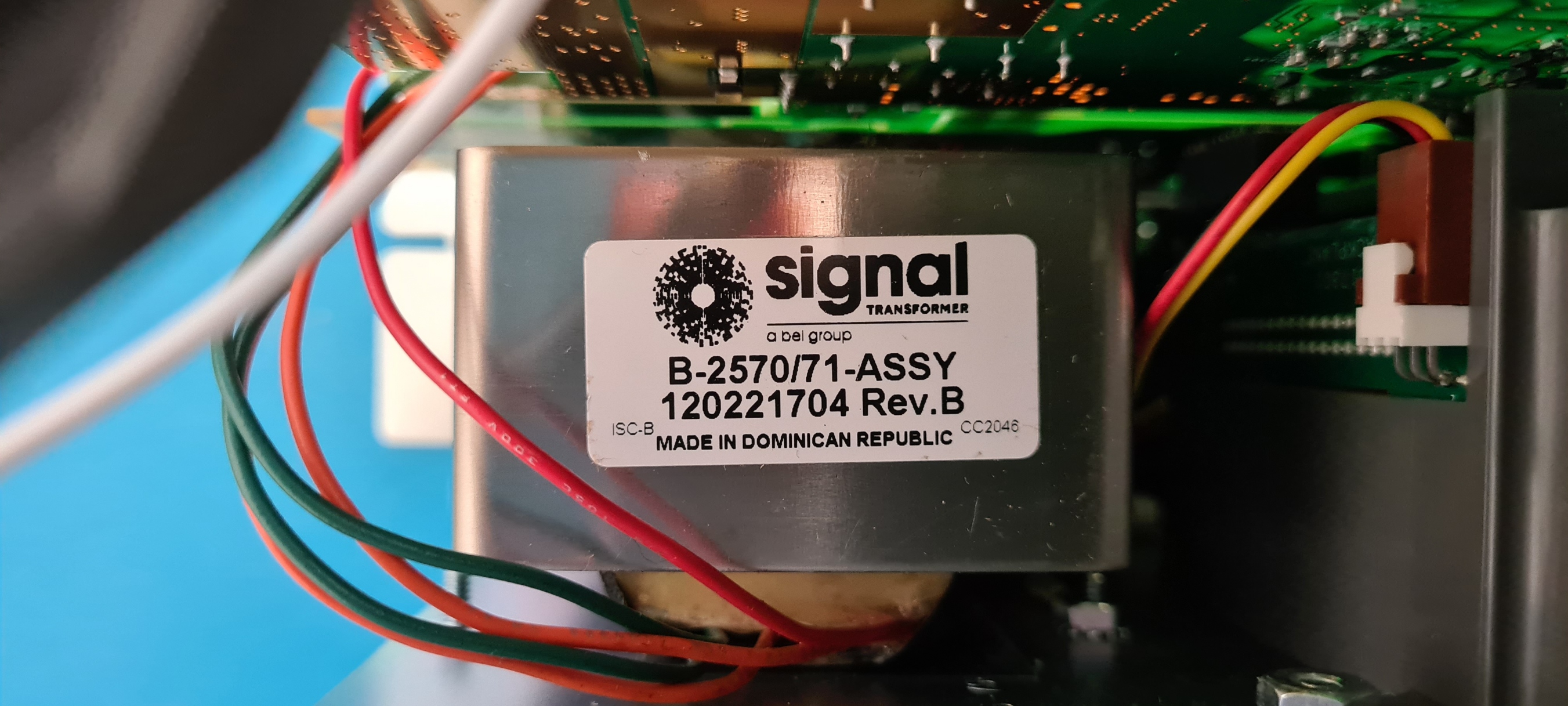
Sadly we can learn that transformer still makes the same horrible hum, no enhancements only the label has been styled. Transformer hum issues were supposed to be fixed since original DMM6500 release to market.
To be updated.
Discussion about this article and related stuff is welcome in comment section or at our own IRC chat server: irc.xdevs.com (standard port 6667, channel: #xDevs.com). Web-interface for access mirrored on this page.
Projects like this are born from passion and a desire to share how things work. Education is the foundation of a healthy society - especially important in today's volatile world. xDevs began as a personal project notepad in Kherson, Ukraine back in 2008 and has grown with support of passionate readers just like you. There are no (and never will be) any ads, sponsors or shareholders behind xDevs.com, just a commitment to inspire and help learning. If you are in a position to help others like us, please consider supporting xDevs.com’s home-country Ukraine in its defense of freedom to speak, freedom to live in peace and freedom to choose their way. You can use official site to support Ukraine – United24 or Help99. Every cent counts.
Modified: Aug. 31, 2022, 2:53 p.m.