Contents
- Intro
- Disclaimer
- Manual references
- Initial inspection and basic disassembly
- Repair workflow and diagnostics
- Firmware
- Other possible issues
- Calibration
- Performance verification
- Restoration summary
Intro
To complete collection, here is coverage and notes regarding likely most popular Keithley DMM, 6½-digit general purpose Model 2000.
This meter is a base for many other units as well, like Model 2015 THD meter, 2700 series. A/D converter from 2000 is also almost completely reused in 24xx series SMU, 2510 and other units.
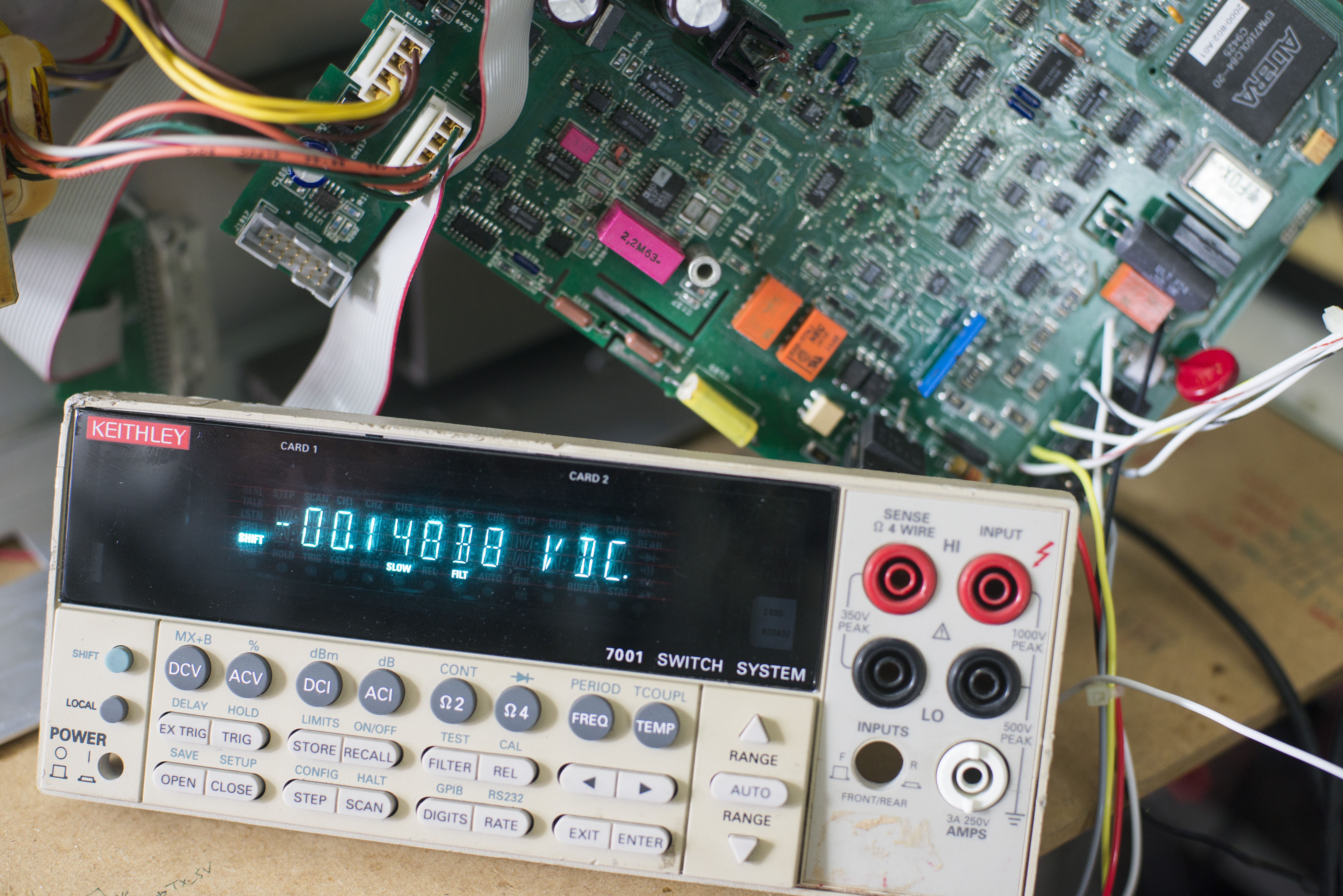
Got this unit as damaged, with physical damage on chassis and housing, but with undamaged VFD.
Compared to other Keithley’s high-end 7½ and 8½ digit DMM platform, Model 2000 using much simpler approach and construction to meet it’s spec.
| Item | Model 2000 | Model 2001 | Model 2002 | Units |
|---|---|---|---|---|
| Resolution | 6½ digits | 7½ digits | 8½ digits | digit |
| A/D converter | Keithley integrating ADC | Keithley multi-slope ADC | Keithley dual-ref multi-slope ADC | |
| Linearity | ±2ppm of reading + 1ppm of range | <1ppm of range typical, <2ppm max) | <0.1ppm of range typical, <0.2ppm maximum | ppm |
| A/D digital domain | ALTERA EPM7160 or custom ASIC | ALTERA EPM7064 or ACTEL | ALTERA EPM7160 | |
| Voltage reference | Selected LM399 | Selected LM399 | Selected LTZ1000ACH | |
| Ohm ISRC | TF-245 resistor network | Vishay thick film res | Vishay foil resistors | |
| Current RSHUNT | 0.1R 4W and 10R thick film | 0.1R and 0.91R wire-wound | 0.1R and 0.91R wire-wound | |
| AC True RMS | AD637 | AD637 | AD637 | |
| Digital board | Same PCB | Separate PCB | ||
| Interfaces | GPIB, RS232, digital I/O | GPIB only, Digital I/O | GPIB only, Digital I/O | |
| Cooling | None | 40×40mm fan | 40×40mm fan | |
| Front panel | Segment single-line VFD | Dual-line dot-matrix VFD | Dual-line dot-matrix VFD | |
| MSRP | $1140 MSRP base | $4690 MSRP base | $6270 MSRP base | $ USD |
Disclaimer
Redistribution and use of this article or any images or files referenced in it, in source and binary forms, with or without modification, are permitted provided that the following conditions are met:
- Redistribution of article must retain the above copyright notice, this list of conditions, link to this page (/fix/kei2000/) and the following disclaimer.
- Redistribution of files in binary form must reproduce the above copyright notice, this list of conditions, link to this page (/fix/kei2000/), and the following disclaimer in the documentation and/or other materials provided with the distribution, for example Readme file.
All information posted here is hosted just for education purposes and provided AS IS. In no event shall the author, xDevs.com site, or any other 3rd party, including Tektronix/Keithley be liable for any special, direct, indirect, or consequential damages or any damages whatsoever resulting from loss of use, data or profits, whether in an action of contract, negligence or other tortuous action, arising out of or in connection with the use or performance of information published here.
If you willing to contribute or add your experience regarding test instruments repairs or provide extra information, you can do so following these simple instructions
Manuals
Model 2000 Datasheet with specsheet
Model 2000 Specifications, Rev. L, / Aug 2011
Model 2000 User’s Manual, Rev. J / August 2010
Model 2000 User’s Manual, Rev. F / April 1999
Model 2000 Repair manual, Rev. B / March 1997
Model 2000 Calibration manual, Rev. F / August 2007
Model 2000 Calibration manual, Rev. С / January 2001
Model 2000 Quick reference guide, Rev. B / December 1999
Model 2000 Quick reference guide, Rev. C / October 2007
Model 2000-SCAN Card Instruction Manual, Rev. F / February 2014
Model 2000-SCAN-20 Scanner Option Specification, Rev. C
Model 2000 Support Software Release Note
Model 2000 KE2000 IVI Instrument Driver 2000-852C01 Release Note for Version C01
Owners of Model 2000 meter from bbs.38hot.net forums reversed schematics for it. Provided as is, use with caution.
Schematics in PDF – Credit jhzyou 126.com
Initial inspection and basic disassembly
Removing metal cover is simple, as with most of other Keithley instruments. There is only one main board installed, with both digital and analog components separated by isolation gap. THD meter Model 2015 does have one extra DSP board and extra transformer for it’s power, so there is lot of empty space in bare Model 2000.
Power supply is based around linear transformer, which have separate windings for analog and digital domains. Analog section power gets rectified by two bridges and further regulated by pair of linear LDOs 7815 and 7915 in TO220 package. These get rather hot, and placed right against input capacitors,
so I would not say it’s best solution. For any second hand unit there capacitors must be removed and replaced with fresh +105°C rated on day one.
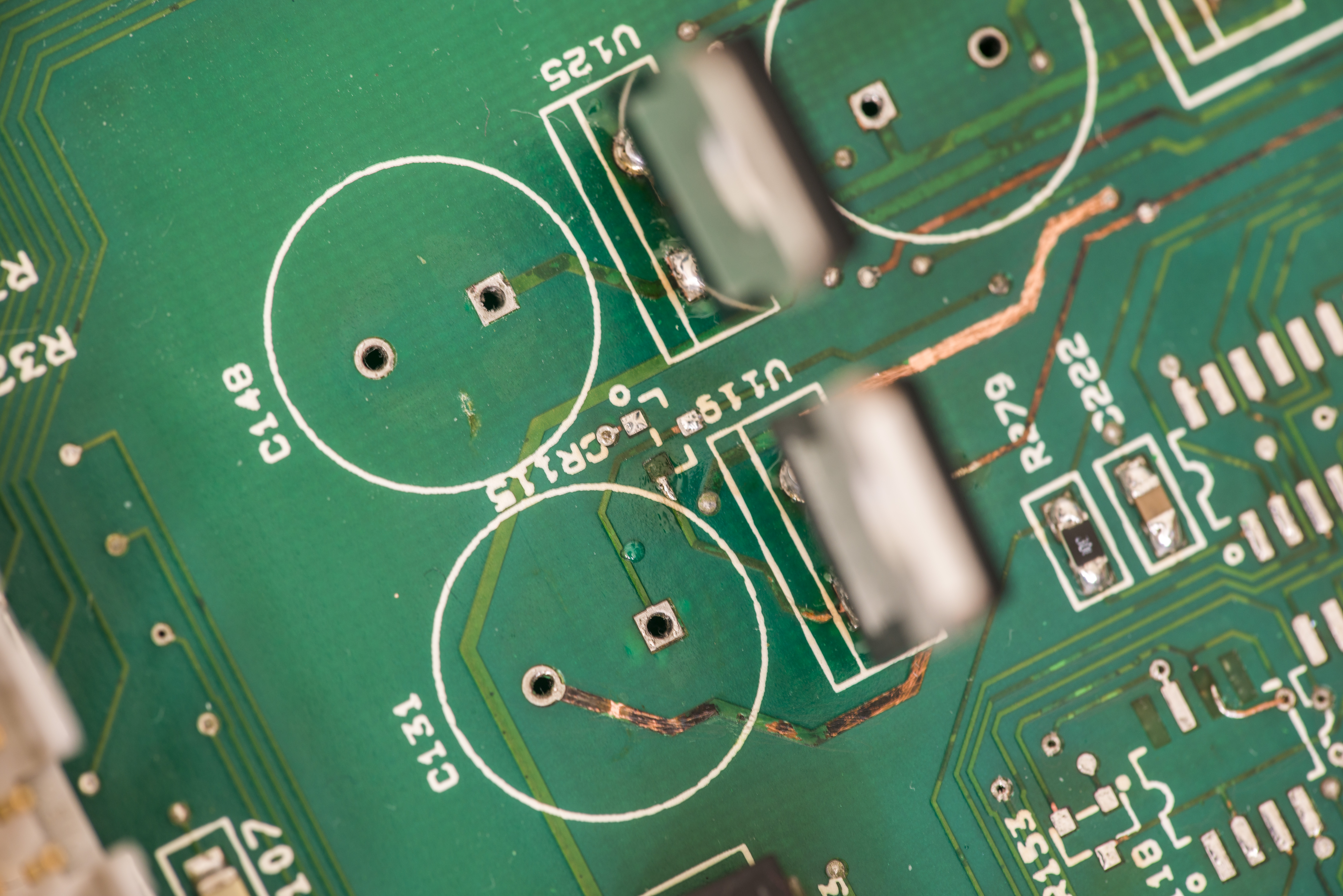
As expected in our old unit (date codes on IC’s are from 1994) capacitors leaked electrolyte and caused mess and damages everywhere around.
More details to that later in repair section.
Digital section have main Motorola 68000 based processor, with some SRAM, EPROM chips (separated by even and odd bytes) and interface chips.
Calibration constants, date and ID data stored in regular I2C EEPROM 24C16 near CPU. Unlike bigger brothers, there is no option for NVRAM storage option.
Expansion cards are accepted by option slot, which is connected to main board via ribbon cable.
Usual 2000-SCAN and 2001-SCAN/2001-TCSCAN cards are compatible with this meter, and operation is covered in user manuals well.
Meter also features both front and rear inputs, switched by big gang switch, in same fashion as 2001/2002.
There are simpler relays being used, in our unit made by NEC, instead of expensive low-leakage reed relays from COTO/AMREL.
Don’t turn it on, take it apart..

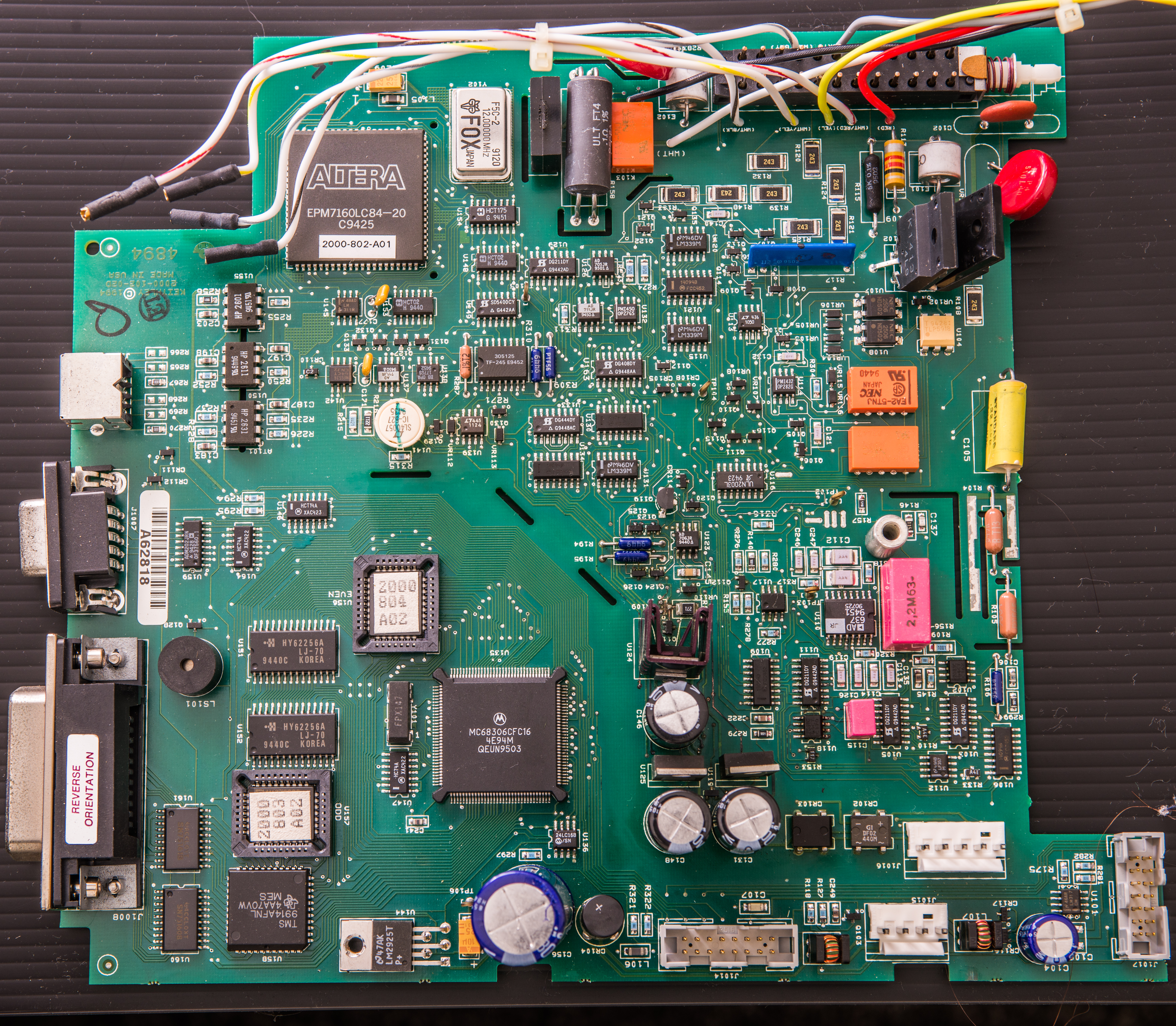
Top side of main-board
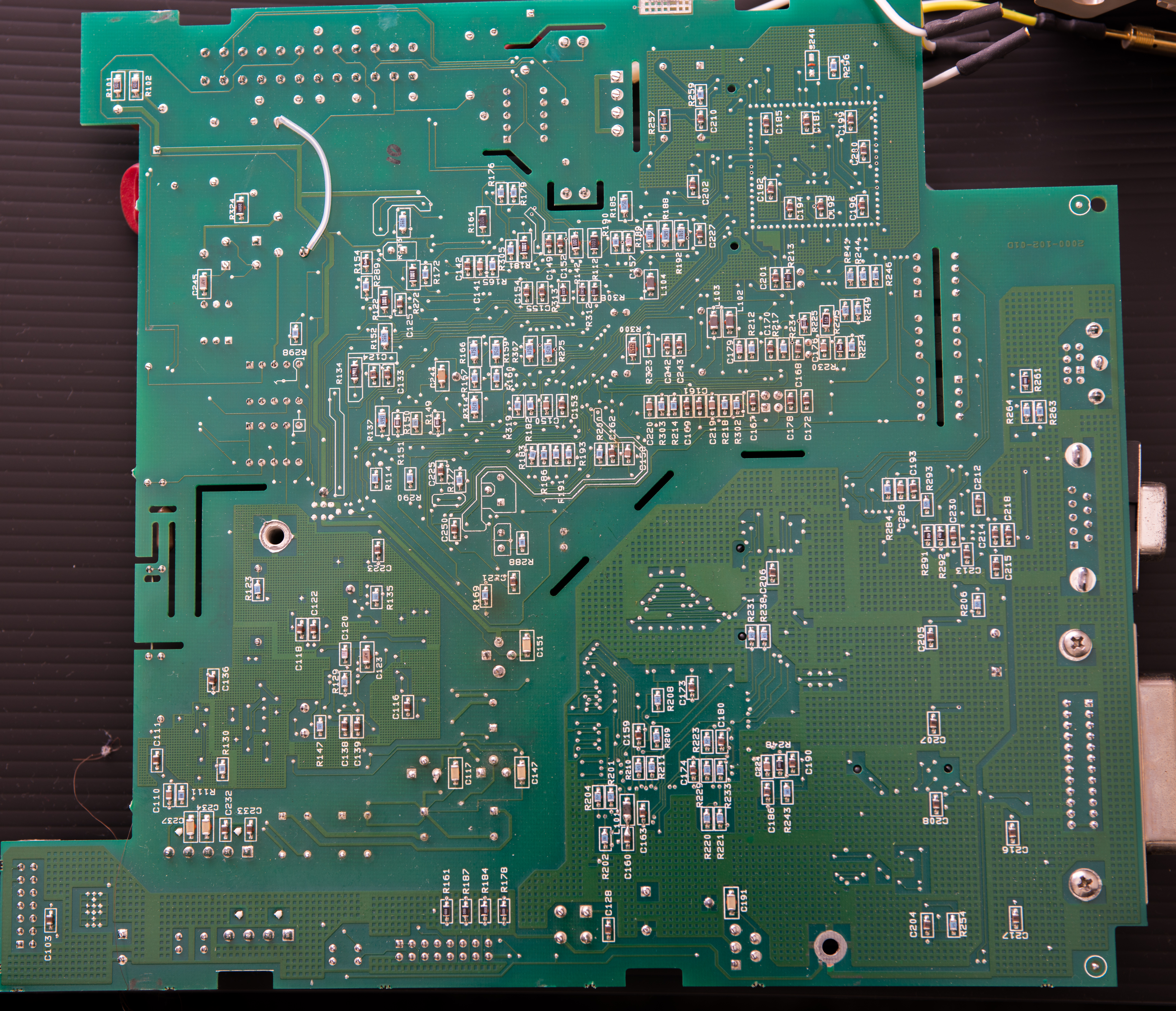
Bottom side of main-board
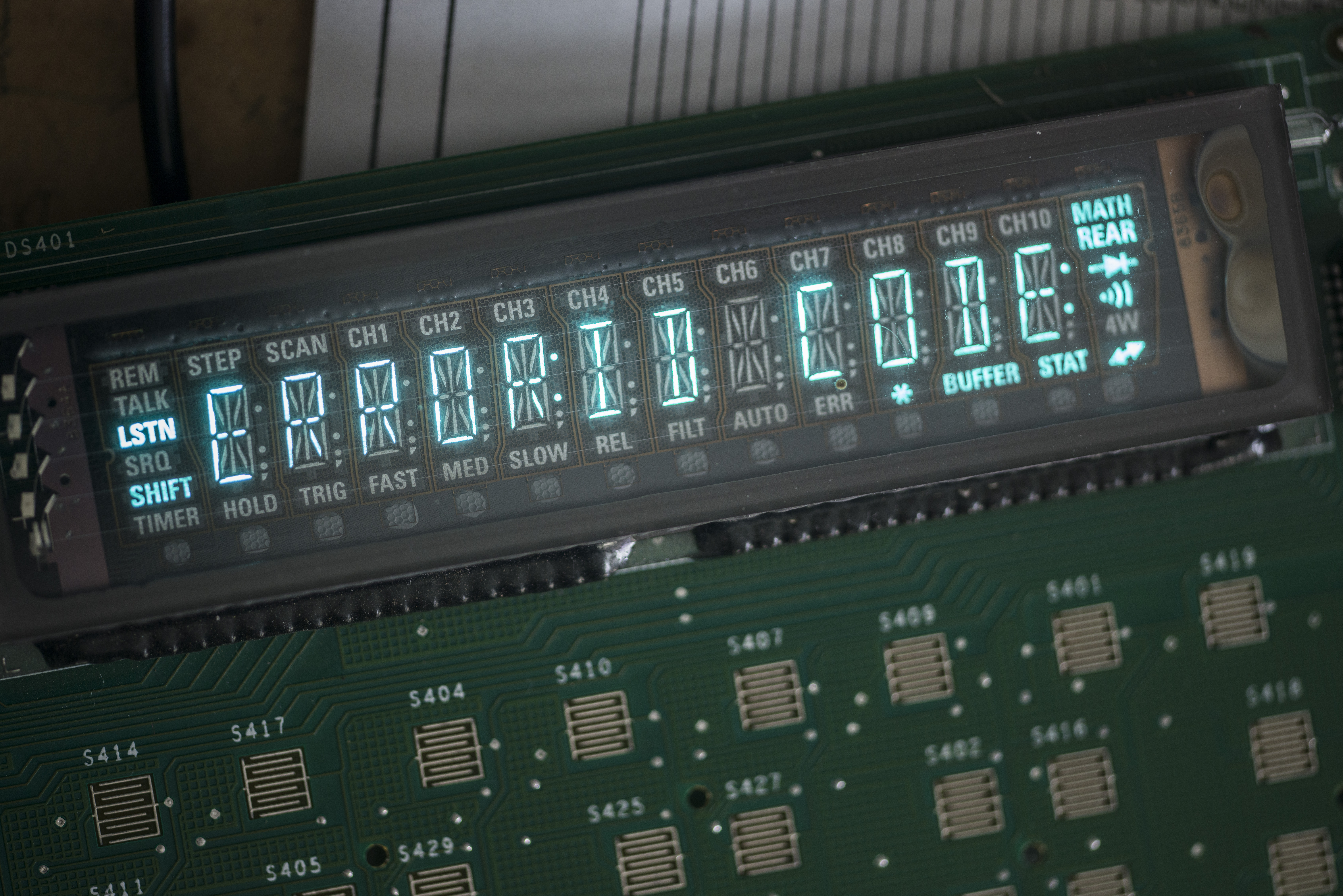
Back of front panel board

Self-test status as received:
Last calibration date: 03/13/1995
Calibration counts: 1
So it was never calibrated after purchase, or simply calibration data was lost.
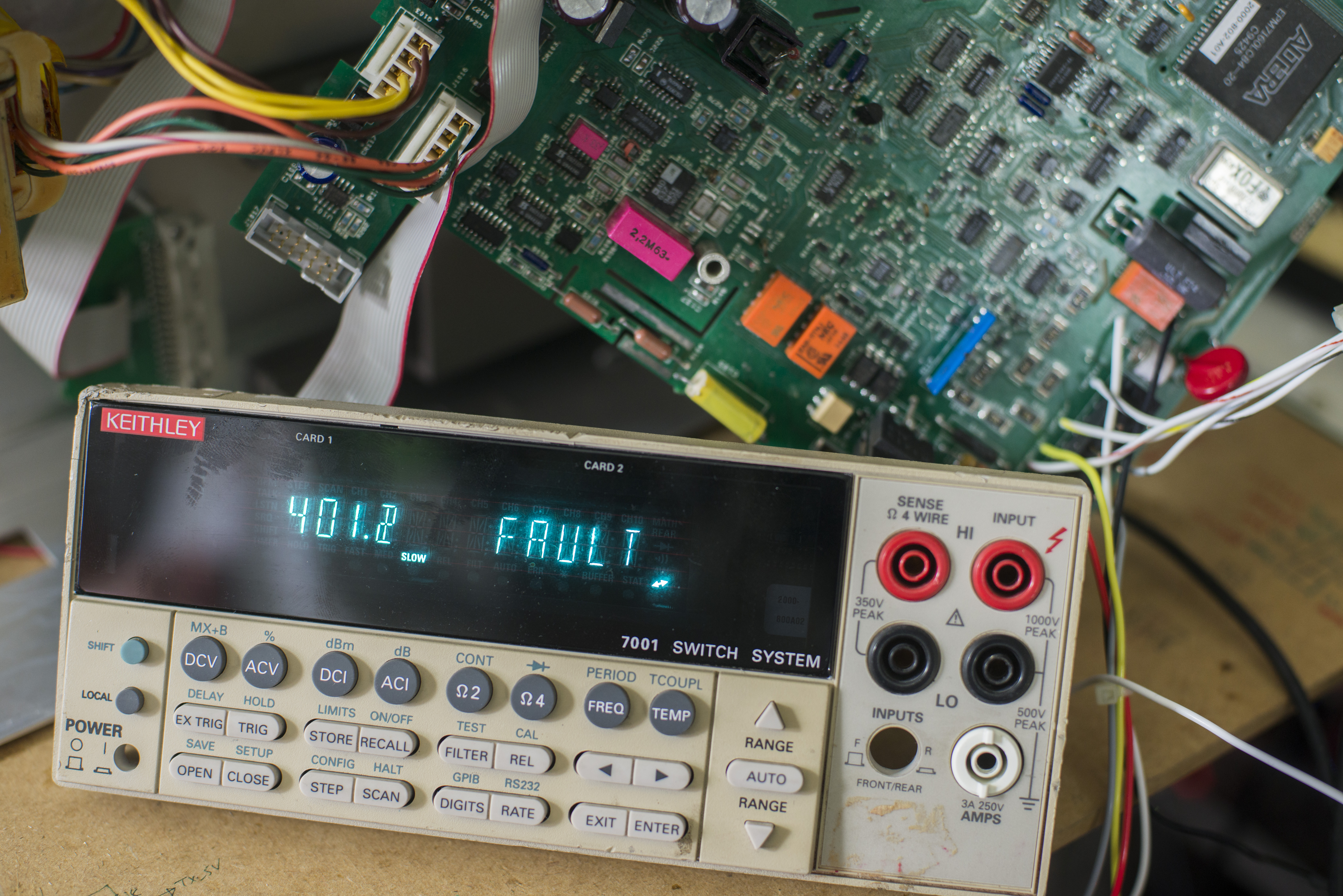
Failed self-test: 100.2, 201.1, 201.2, 300.1, 301.1, 301.2, 302.1, 302.2, 303.1, 303.2, 304.1, 400.2, 401.2, 402.2, 403.2, 500.1, 500.2, 600.1, 600.2, 601.2
Input VDC signals or resistances are not measured correctly, random values are displayed instead.
Repair workflow and diagnostics
Power supply repairs, board recap
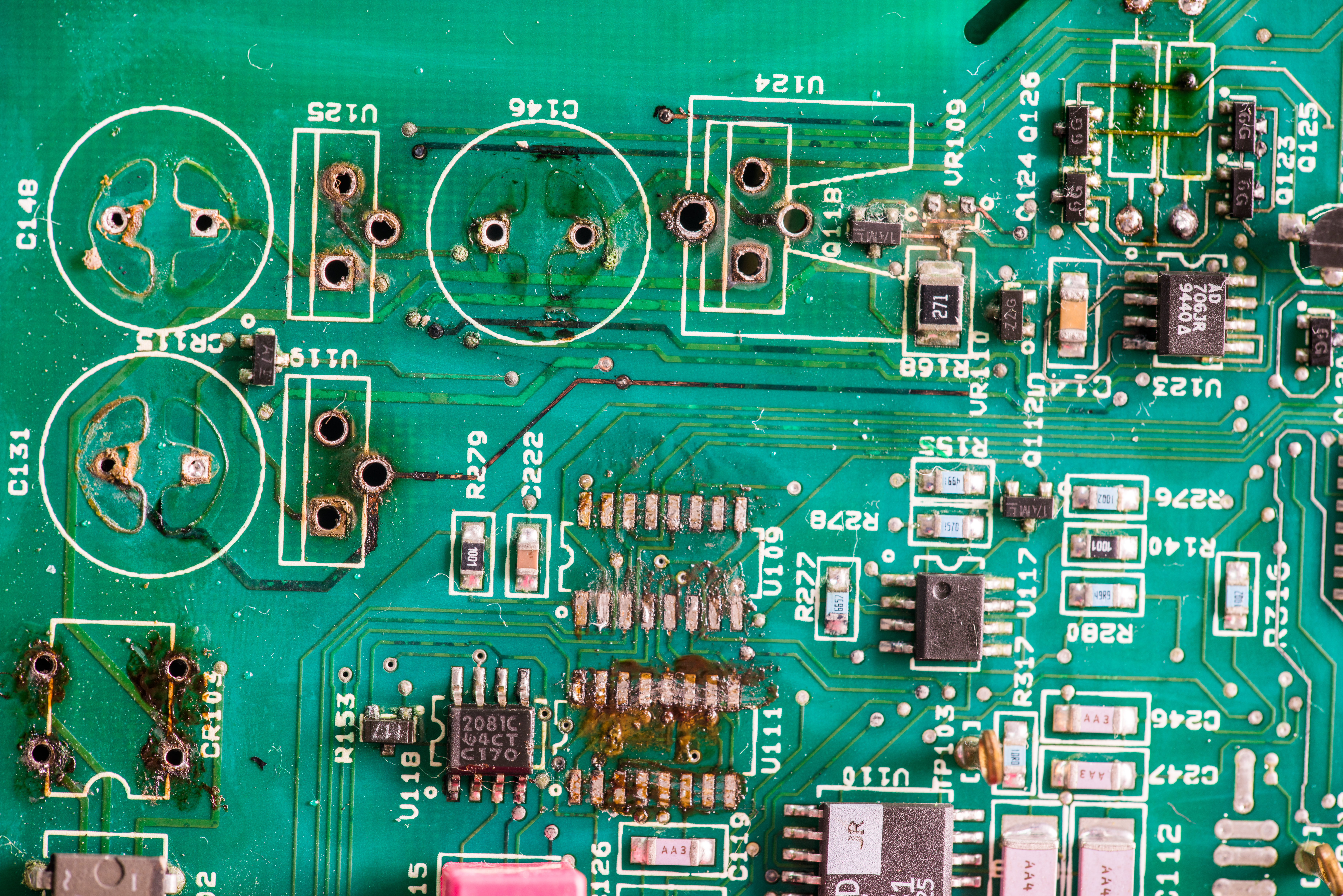
First we need clean electrolyte from leaked capacitors. To do so some stuff need to be desoldered first, and all traces around should be probed, to make sure they are not open/broken. Usual to have trace neck around small vias eaten, causing opens. Specially considering Model 2000 is using 4-layer PCB.


Installed new 7815, 7915, 7805, some passives, new DG211, DG411 (did not had extra DG211)
Checking components around area which was contaminated by electrolyte revealed dead R153 (instead of 3.6К+3.6К mine was reading 3.6К+9К).
Replaced it with temporary pair of generic 0603 3.6К to test. Did not have 17V zener in stock, so temporarily installed pair of 11V 6.2V zeners in series. That circuit together with BJT is used to provide +17V to AD706 op-amp.
Also replaced some JFETs, U109 (14094B register), U111 (DG211DY) from my donor 2001 yesterday night, few errors go away, such as 201.1, 201.2, 300.1, 301.2, 303.2.
Other tests still failed: 100.2, 301.1, 302.1, 302.2, 303.1, 304.1, 400.2, 401.2, 402.2, 403.2, 500.1, 500.2, 600.1, 600.2, 601.2
But still after these replacements DMM reading garbage and random reading, even with input shorted or given fixed voltage.
Switch replacement
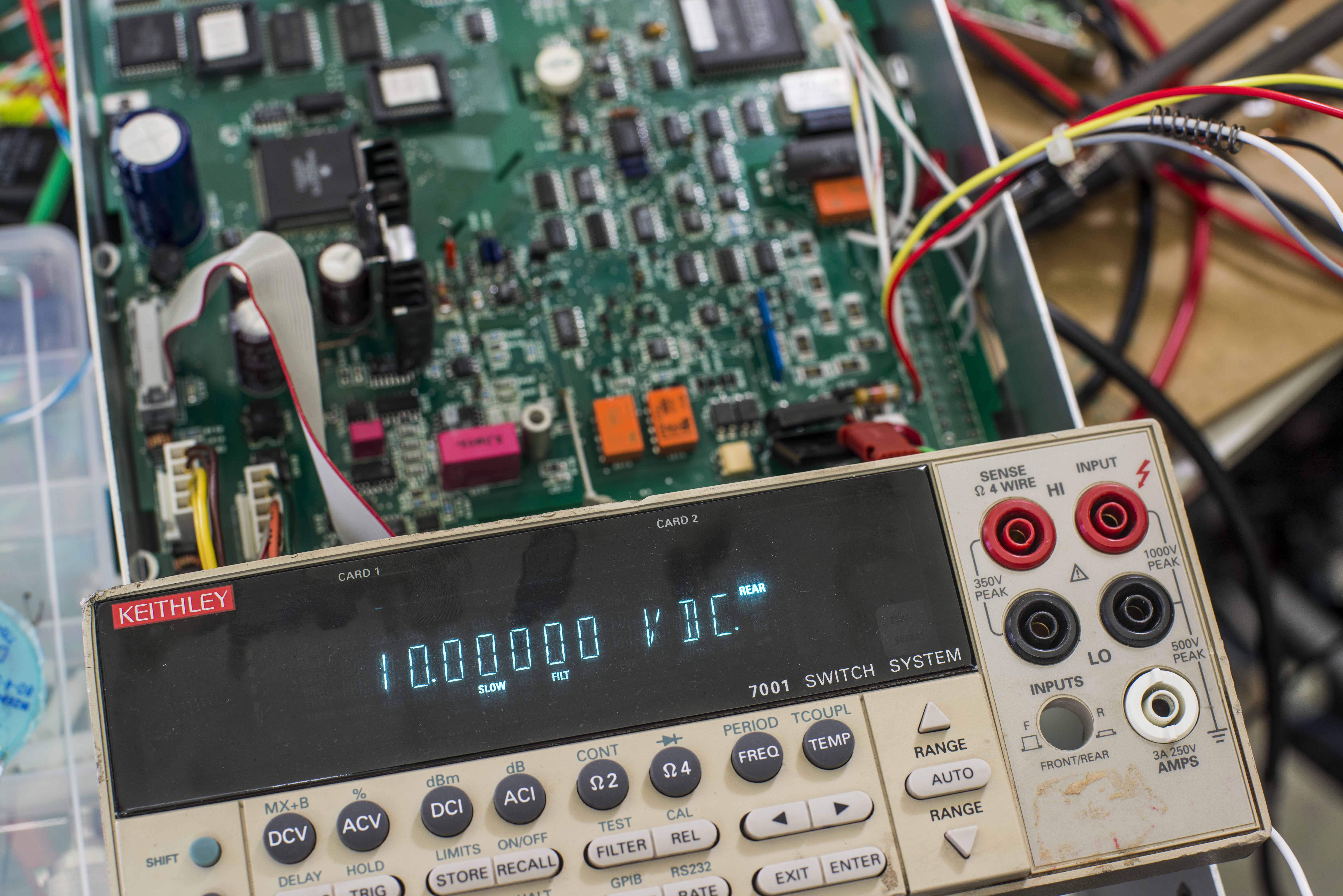
As next step of troubleshooting, let’s trace where input signal getting corrupted/lost. To do so, 10.0000VDC generated from DC standard EDC MV106 was applied to DMM’s input and voltage traced with Keithley Model 2001 along the signal path.
Actually any other stable voltage source and usual 4.5-digit DMM would do job also, so there are no requirements to use such precision gear for such simple troubleshooting, it was just what I had running on bench nearby during debug.
Connect input signal as 10 VDC, probes from external DMM connected to input probes of repair unit.
Input resistors – checked, measured 10V on other end.
Input divider – checked, OK.
Relay – check, OK
Protection MOSFETs, check, OK
So high input seem to be fine at least before all attenuating/ranging switch circuitry starts. Can it be negative terminal?
Connecting LO of external DMM to meters AGND (test point TP102) as it should be low resistance path to AGND anyway, as all input signal front-end referenced to AGND. Whoa, resistance between AGND and black wire for front panel is kiloohms range, which is not right.
Spotted problem quickly, it’s a gang switch responsive for rear/front terminals switching. I replaced switch with a new one. Keithley’s part number for ordering is SW-468.
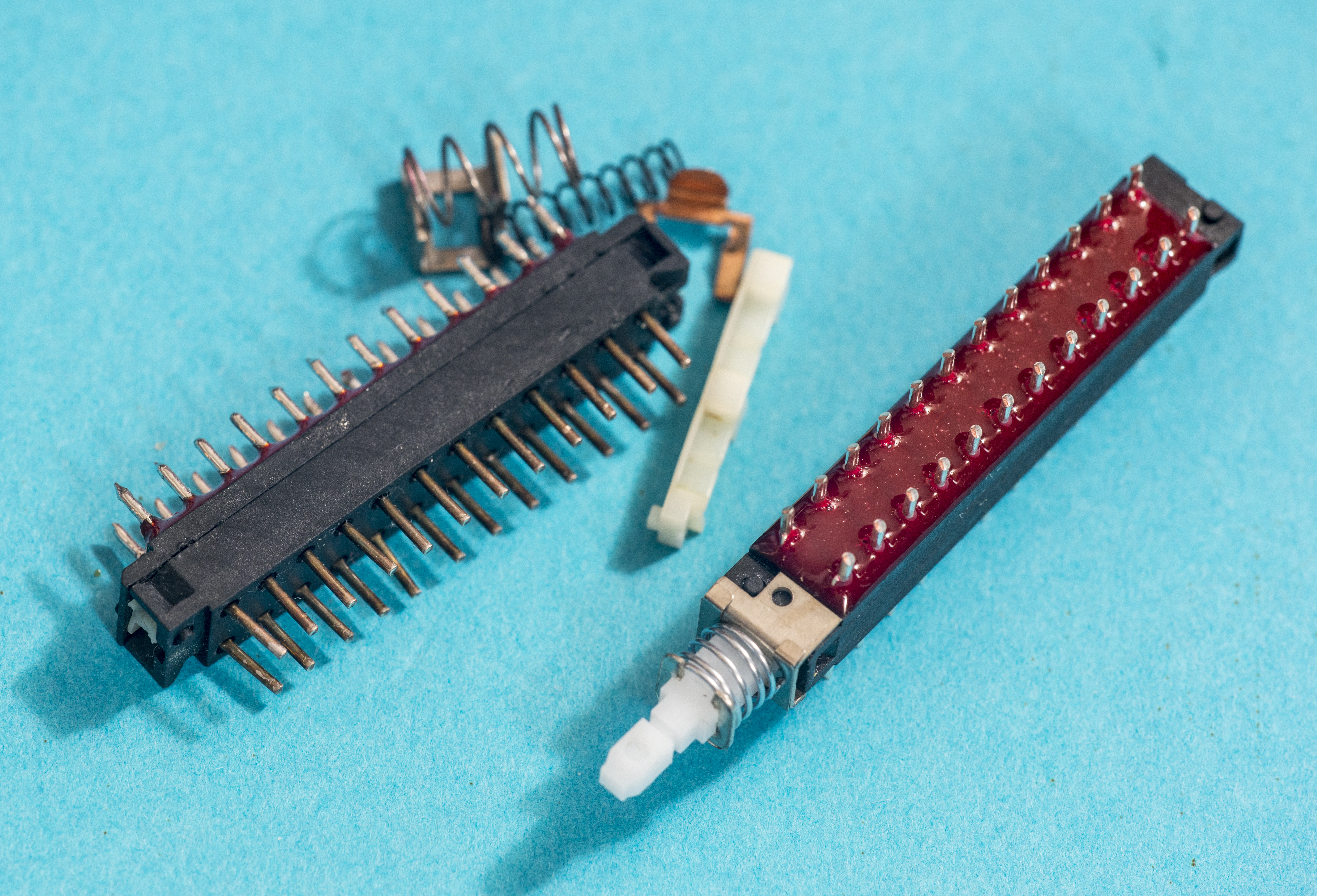

Or if you want to save some cost, you can carefully disassemble switch and clean it’s wipers, like shown on photo below:
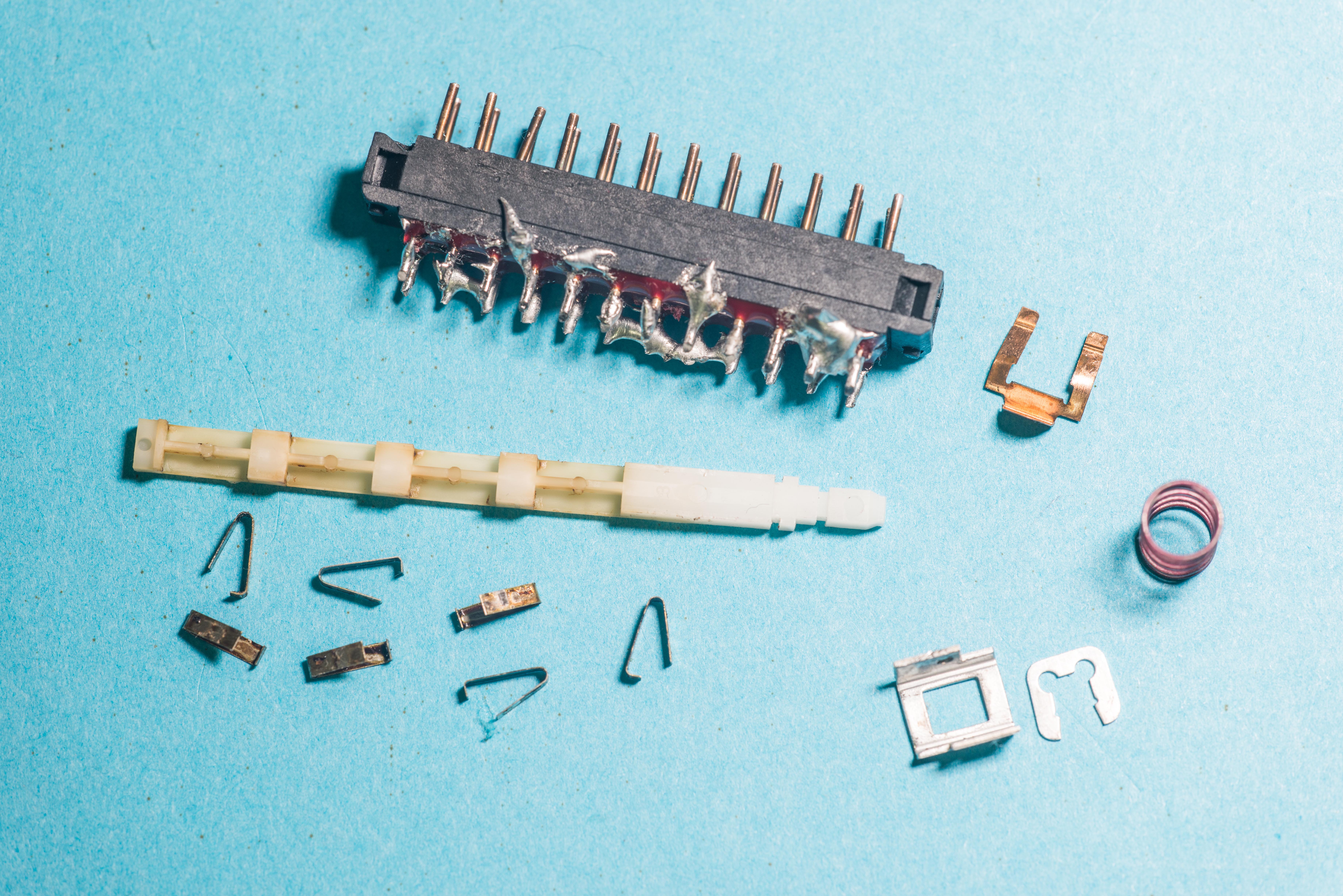
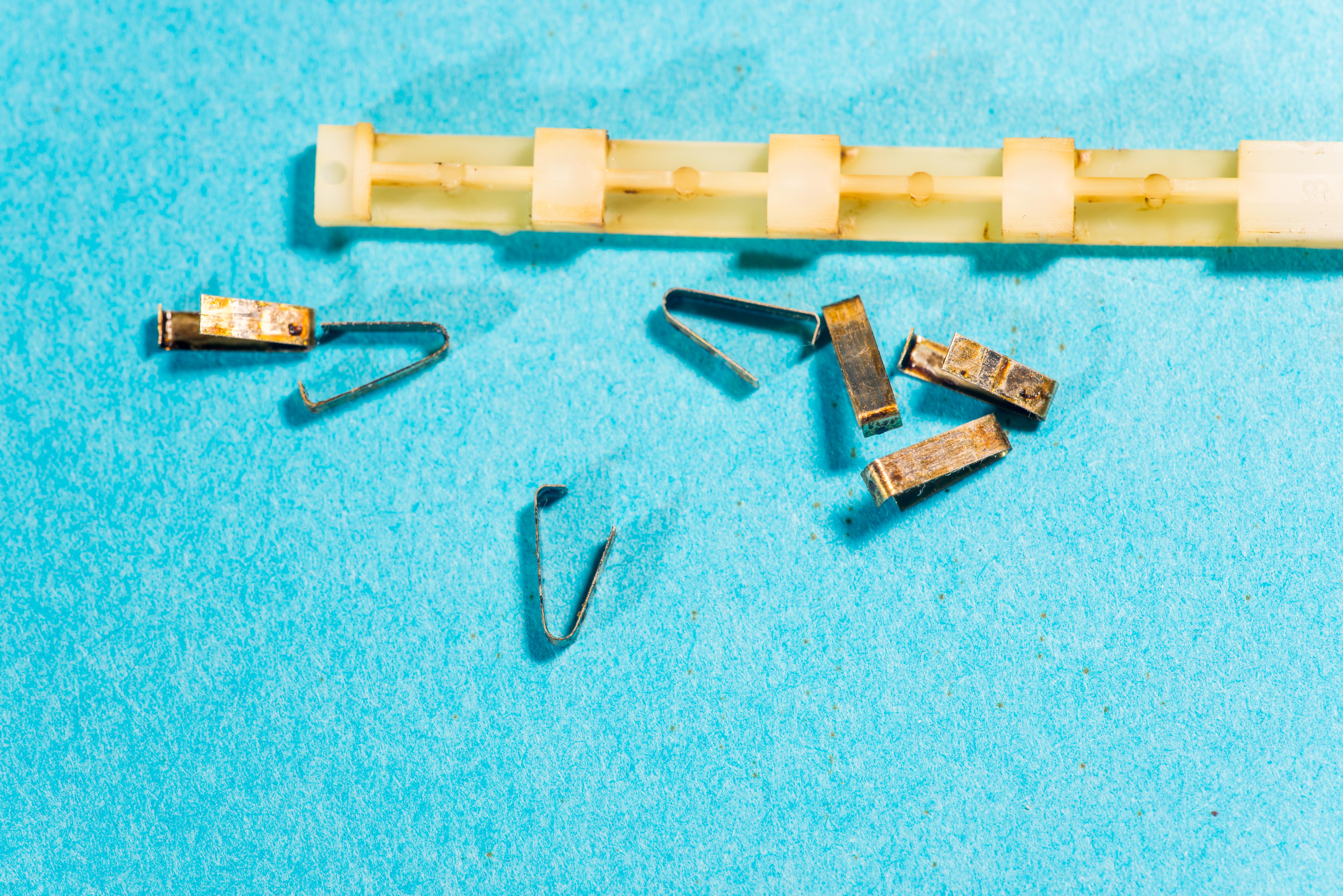
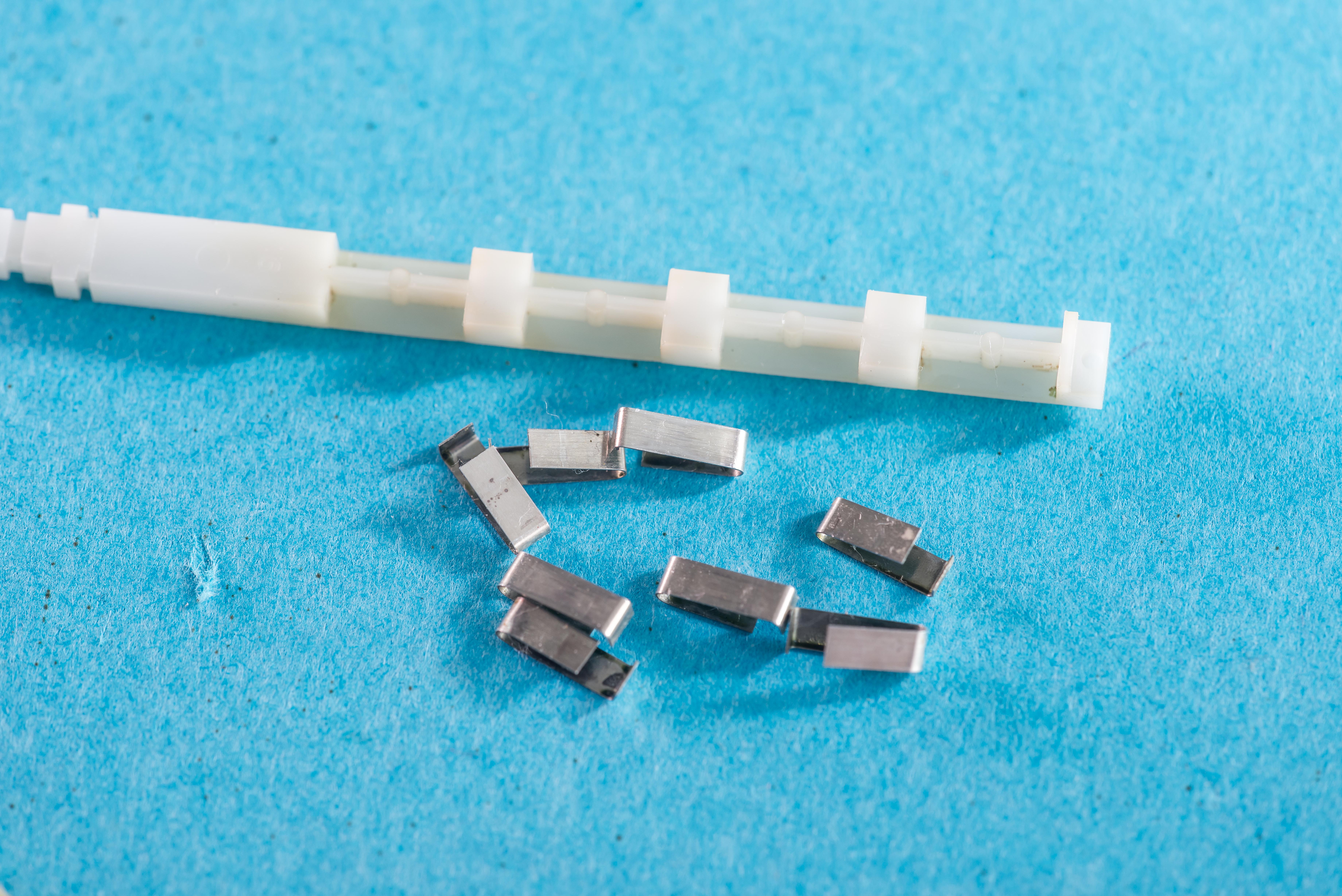
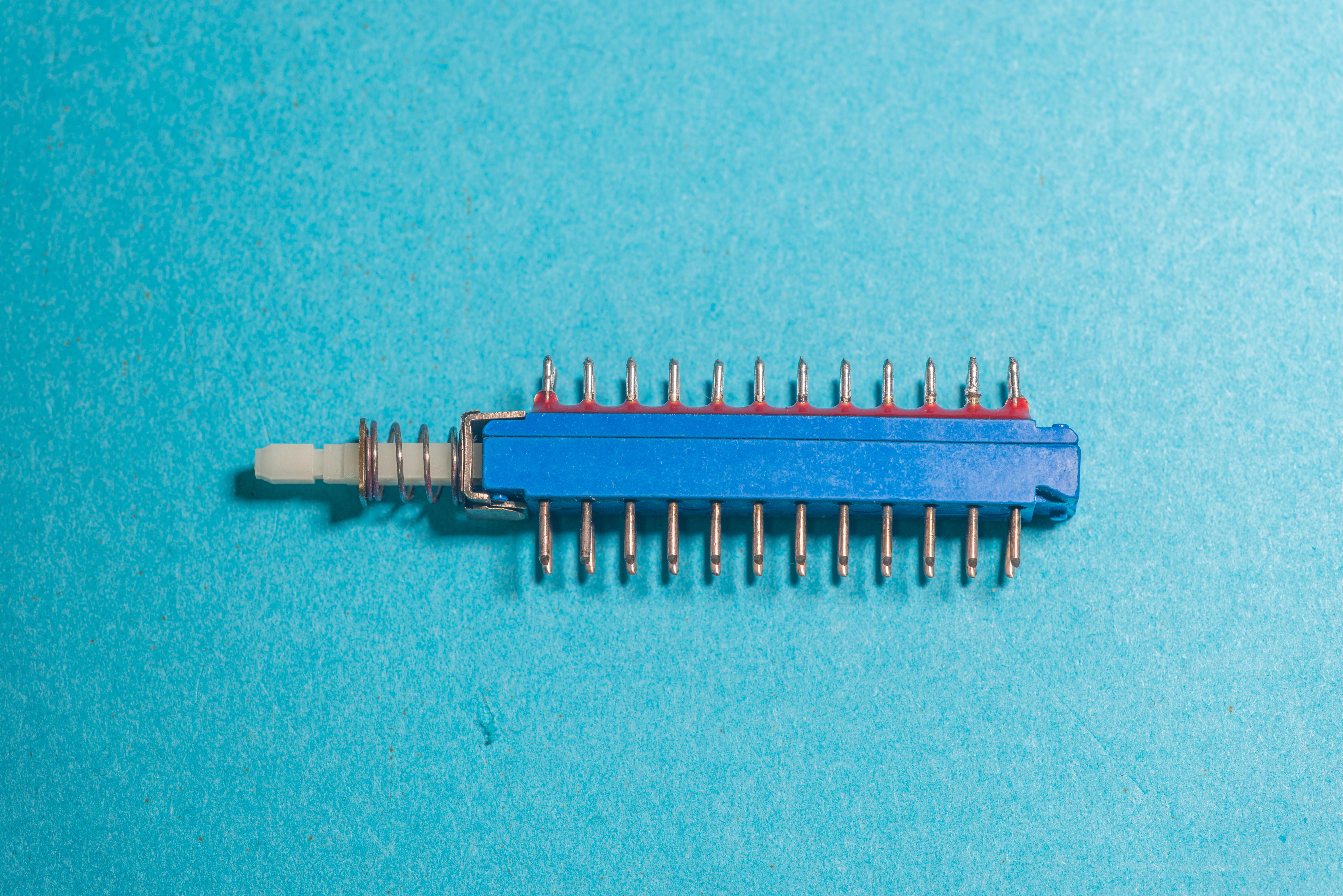
Beware wipers direction, it’s important to have them position right, otherwise they will lock inside and you will be never able to use switch again. Also make sure spring mechanism for lever lock working correctly. It pretty fragile and easy to damage.
After fixing issue with switch, we finally get some good measurements of signal at input terminals. It was also confirmed before new switch installation:
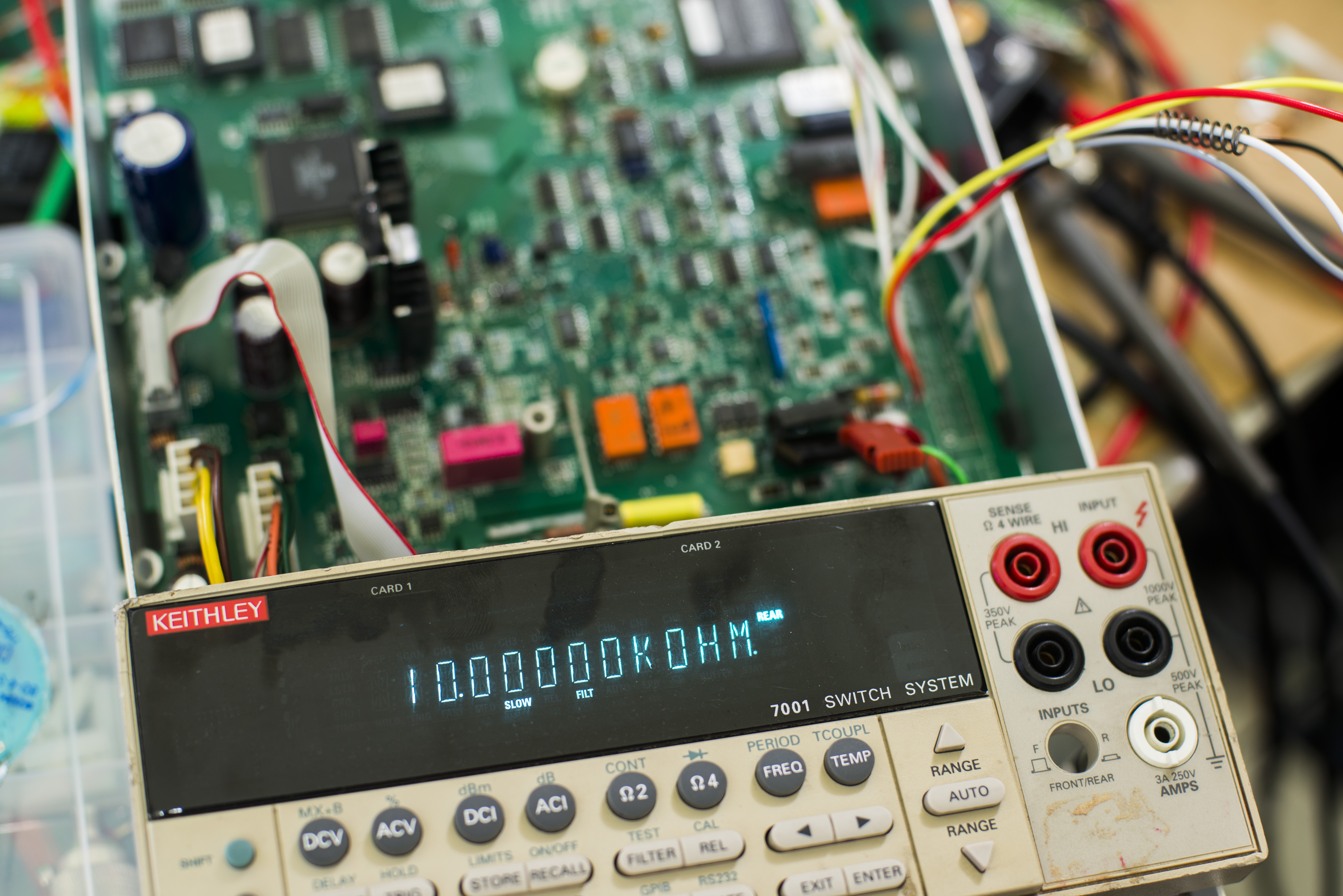
Self-test error 302.2 and 303.1 are fixed as well after switch removal.
Errors 4xx troubleshooting
One of common problems is TF-245 resistor network used in many 2000 series DMMs and 24xx series SMUs. So it was desoldered and values are measured and compared to other known good results. Test data summary is in table below:
| Pin A | Pin B | Schematic value | Measured value | Delta, ppm | #1 | #2 | #3 | #4 |
| 1 | 16 | 1.00000K | 1.00206K | +2060 | 0.9999K | 1.0002K | 1.0002K | 0.9997K |
| 16 | 2 | 9.00000K | 9.00905K | +1006 | 8.9999K | 8.9989K | 8.9999K | 8.9960K |
| 2 | 15 | 10.0000K | 10.00842K | +842 | 10.0001K | 9.9985K | 9.9995K | 10.0030K |
| 15 | 3 | 20.0000K | 20.00163K | +81.5 | 20.000K | 20.000K | 19.996K | 19.990K |
| 3 | 14 | 15.0000K | 15.00905K | +603 | 14.9995K | 15.0035K | 14.9973K | 15.0012K |
| 14 | 4 | 30.1768K | 30.21043K | +1115 | 30.173K | 30.168K | 30.173K | 30.176K |
| 4 | 13 | 29.7070K | 29.70606K | -31.5 | 29.708K | 29.697K | 29.700K | 29.704K |
| 5 | 11 | 30.1760K | 30.17733K | +44.2 | 30.178K | 30.166K | 30.176K | 30.174K |
| 6 | 9 | 1.00000K | 1.00188K | +1880 | 1.0003K | 1.0000K | 1.0001K | 1.0006K |
| 7 | 9 | 9.00000K | 9.00814K | +905 | 9.0040K | 8.9990K | 8.9993K | 9.0007K |
| 7 | 8 | 90.0000K | 90.00001K | +0.2 | 90.001K | 89.979K | 89.982K | 89.990K |
| 10 | 12 | 27.4200K | 27.42557K | +203 | 27.421K | 27.415K | 27.416K | 27.417K |
Also fragment of schematics from bbs.38hot.net reveal expected values and pinout inside TF-245:

Based on this information and measurements TF-245 in this case is fine.
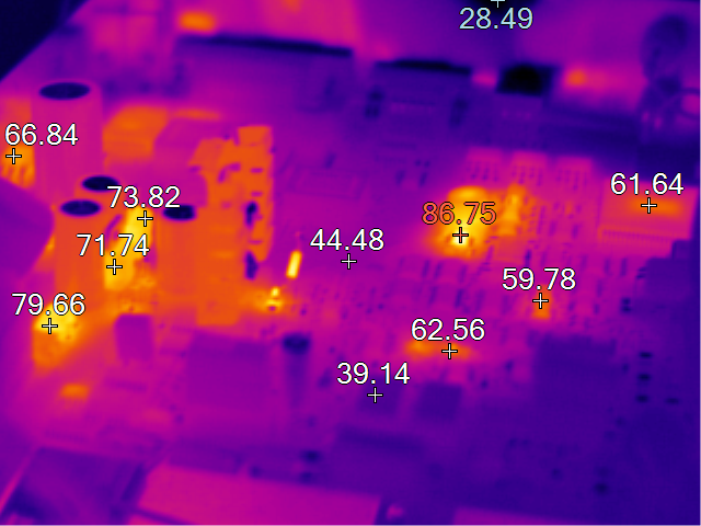
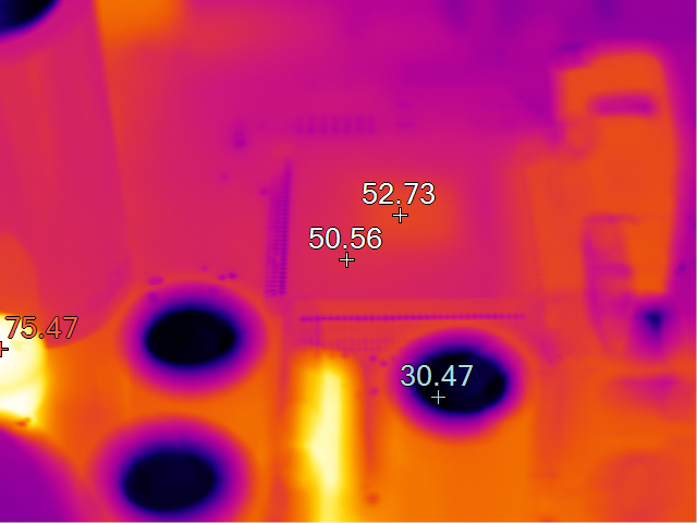
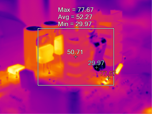
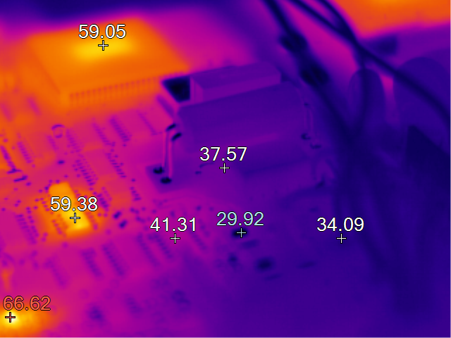
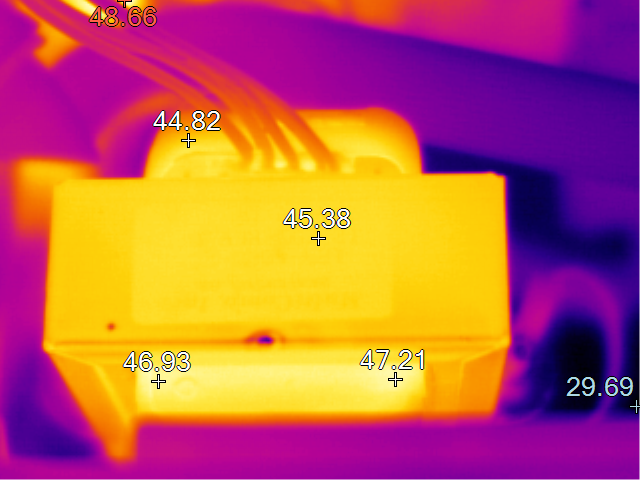
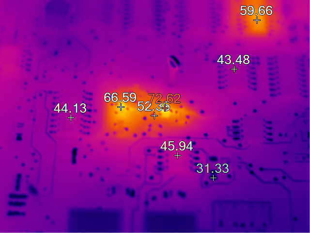
Thermal images of Keithley 2000 PCB
Here are current state thermal photographs of K2000’s internal components.
Overall view and ADC CPLD
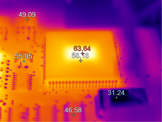
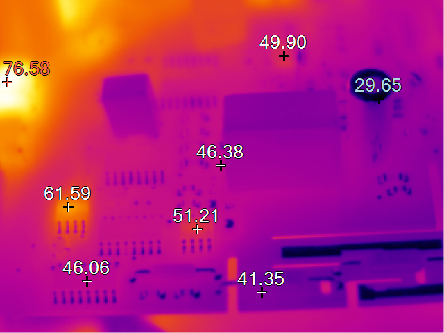
LM399 voltage reference and GPIB controller:
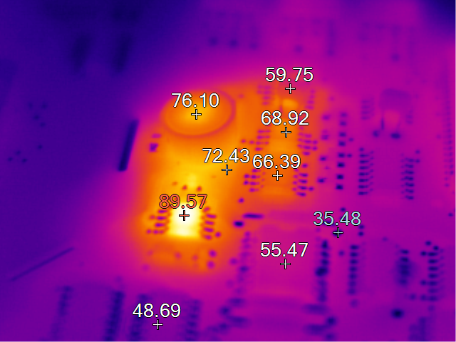
Processor and TRMS circuitry:
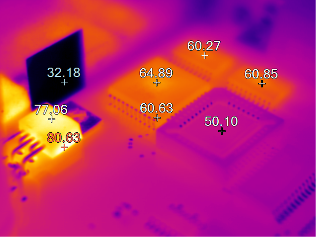
Powersupply and opamp reg:
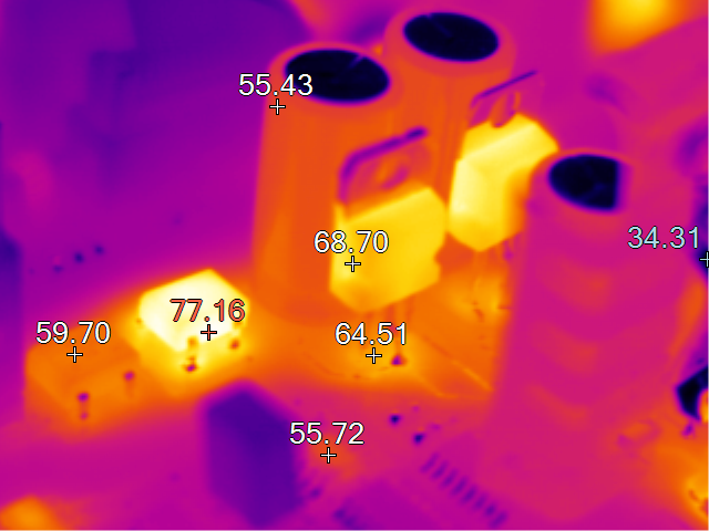
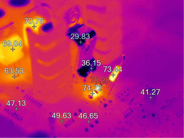
LDOs and input section:
Transformer and some discrete components.
After repairs and firmware upgrade to A19 meter still was throwing few self-test errors, 306.2 and 306.4 to be exact. Repair manual was based on older firmware and don’t have description of those tests, but on Keithley/Tektronix forums someone had same issue and here’s bits of information about these error codes:
This error can happen when relative humidity is too high. Try to dry out the 2000 and operate it in lower humidity.

Below is a description of error 306.2

Recommendation is to clean the PCB area around the components with IPA and clean all the related components. See if this cleaning eliminates the error. pA level errors can be induced by finger oil smudges on circuit boards.
306.2
The +7V reference is switched to REFBOOT. This +7V, which is used as the ohms circuit as a voltage reference, is switched by U133 pins 2 to 3 (/7V control line low) to op amp U123 unity gain buffer. +7V now appears as REFBOOT and is routed through R272, Q109 (/HIOHM control line is low), the 9.9M half of R117, R115, Q101, Q102, K101 pins 3 to 4 (/RESETK2 control line is high), R304, Q104 (LOV control line is high) to U113 BUFCOM. To actually calculate the bias current use the formula;

Bias current in pA = (306.2 reading - 306.1 reading) / 9.9E6
So I’ll try cleaning board and see if these issues get fixed.
Nope, still there. Initially meter PASS self-test, but after warm-up after about 15 minutes errors 306.2 and 306.4 are back. Further investigation revealed, that new firmware on older hardware board will always cause these errors due to leakage. These do not affect calibration or accuracy of the meter directly, however.
Firmware
| Model 2000 firmware version | Complete binary | 2000-803-xxx ODD | 2000-804-xxx EVEN |
|---|---|---|---|
| Version A01 | 2000-803-A01 Bin | 2000-804-A01 Bin | |
| Version A02 | 2000-803-A02 Bin | 2000-804-A02 Bin | |
| Version A05 – Thanks to K04BB | Full binary | 2000-803-A05 Bin | 2000-804-A05 Bin |
| Version A06 | 2000-803-A06 Bin | 2000-804-A06 Bin | |
| Version A07 – Thanks EdoNork | 2000-803-A07 Bin | 2000-804-A07 Bin | |
| Version A12 | 2000-803-A12 Bin | 2000-804-A12 Bin | |
| Version A13 | 2000-803-A13 Bin | 2000-804-A13 Bin | |
| Version A14 – Thanks Marcus G. | 2000-803-A14 Bin | 2000-804-A14 Bin | |
| Version A15 | 2000-803-A15 Bin | 2000-804-A15 Bin | |
| Version A17 | 2000-803-A17 Bin | 2000-804-A17 Bin | |
| Version A19 | 2003-803-A19 Bin | 2000-804-A19 Bin | |
| Version A20 | Full binary, alternative | 2000-803-A20 Bin | 2000-804-A20 Bin |
Firmware upgrade A20 require recalibration of the instrument, if your original firmware version was A19 or below! If you replace firmware on older unit to A20 original calibration will be lost/corrupted.
If you have firmware version dumps which are not listed in table above, please upload them to our FTP.
One of members on EEVBlog forums reported successful using of SST39SF020A-70 FLASH ROMs instead of old EEPROMs in his Model 2000.
I bought some of these FLASH EEPROMs and can indeed confirm correct operation of Model 2000 with these FLASH firmware chips. It makes further upgrades easy with generic programmer like TL866. Photo below show TL866 programmer with Flash chip in the PLCC-DIP adapter.
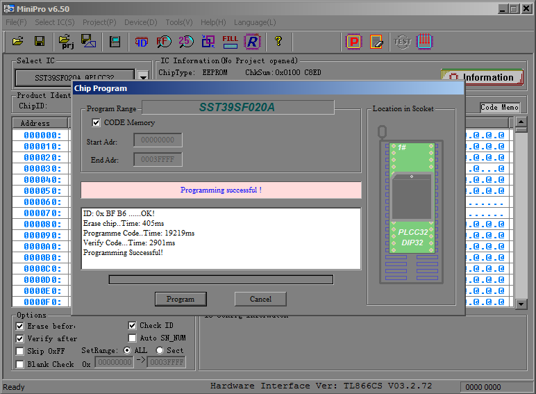
Other similar NOR Flash 2Mbit devices in PLCC32 package should be possible to use as well, because interface and pinout are common standard. Make sure chip interface is plain parallel I/O, not LPC or FW protocol as often found in PC motherboards as BIOS ROMs. Those ICs usually have partnumber starting from x49Fxxx. Such ROMs will NOT work in Keithley 2000!
Other possible issues
Series resistors on from input terminals (large 24K SMT networks near front/rear switch) are often get damaged and invisible pads peeling off, preventing good contact. This is diagnosed by random readings or unstable operation with known good input signal.
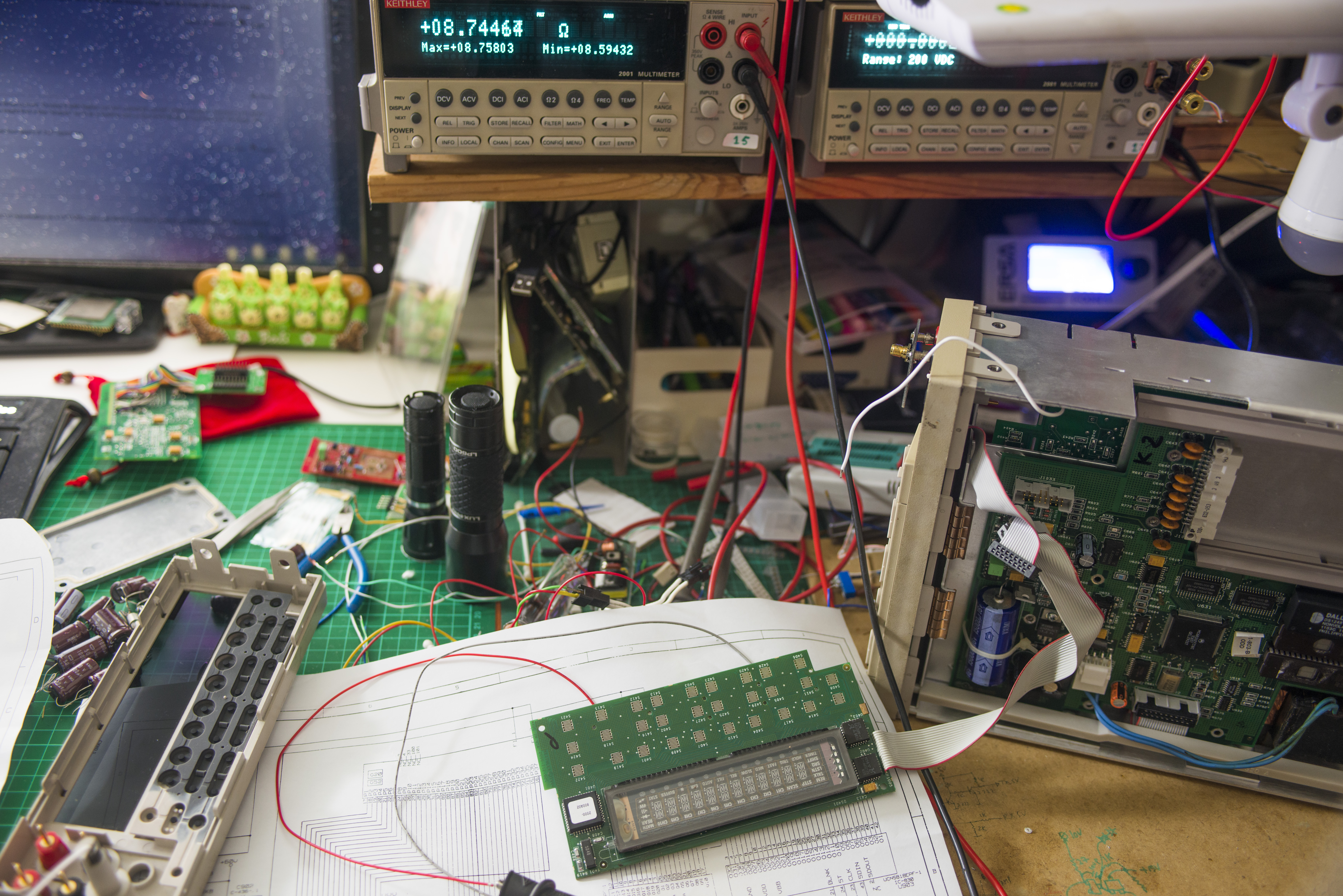
VFD brightness fix/workaround
Today seem to be a good day for some fiddling with my broken 2000. One of issues, disregarding broken analog circuits is really really dim display. On usual daylight it was completely invisible, even without dark plastic plexiglass screen.
I tried to take photo of original state:
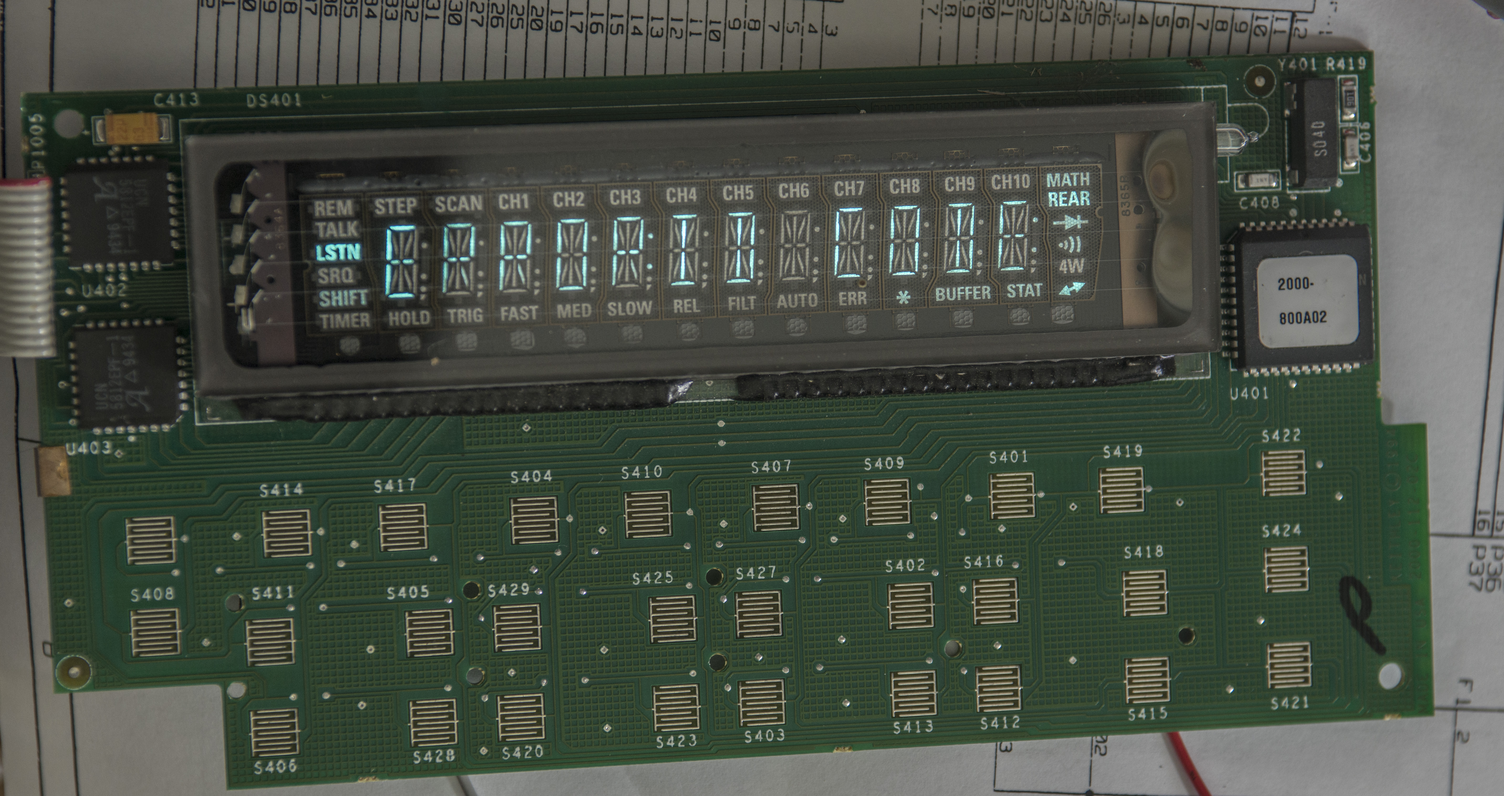
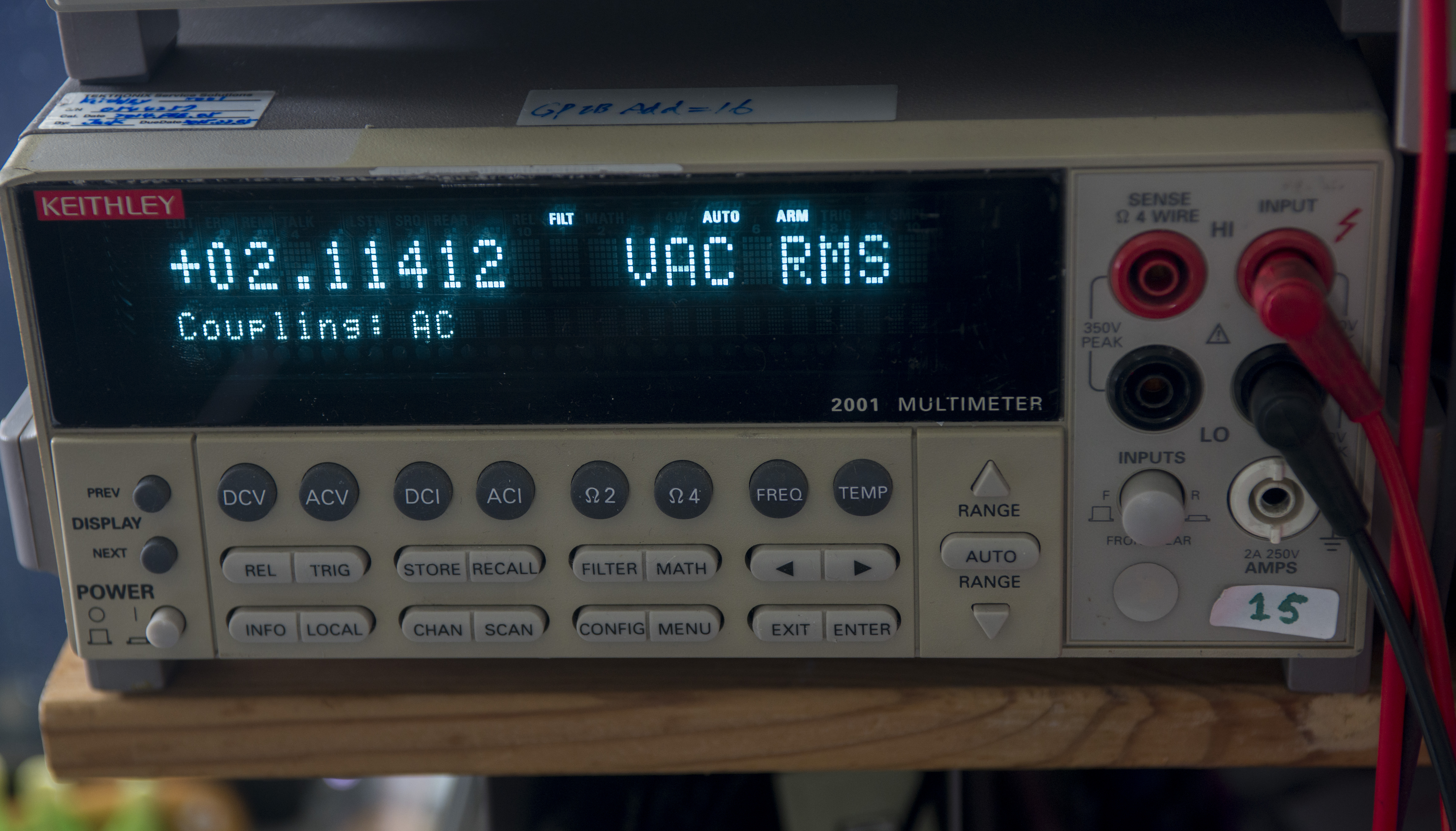
Filament had 8.75 ohm resistance and had 2.11VAC across it during operation.
VFD brightness drop from two reasons:
- Phosphorus become aged if segments are on for long periods. This is visible by dim patterns on screen.
- Filament loose emission due oxidation
Not much can do for fixing segments itself, but we can try deoxidize filament and increase current across it to have more emission.
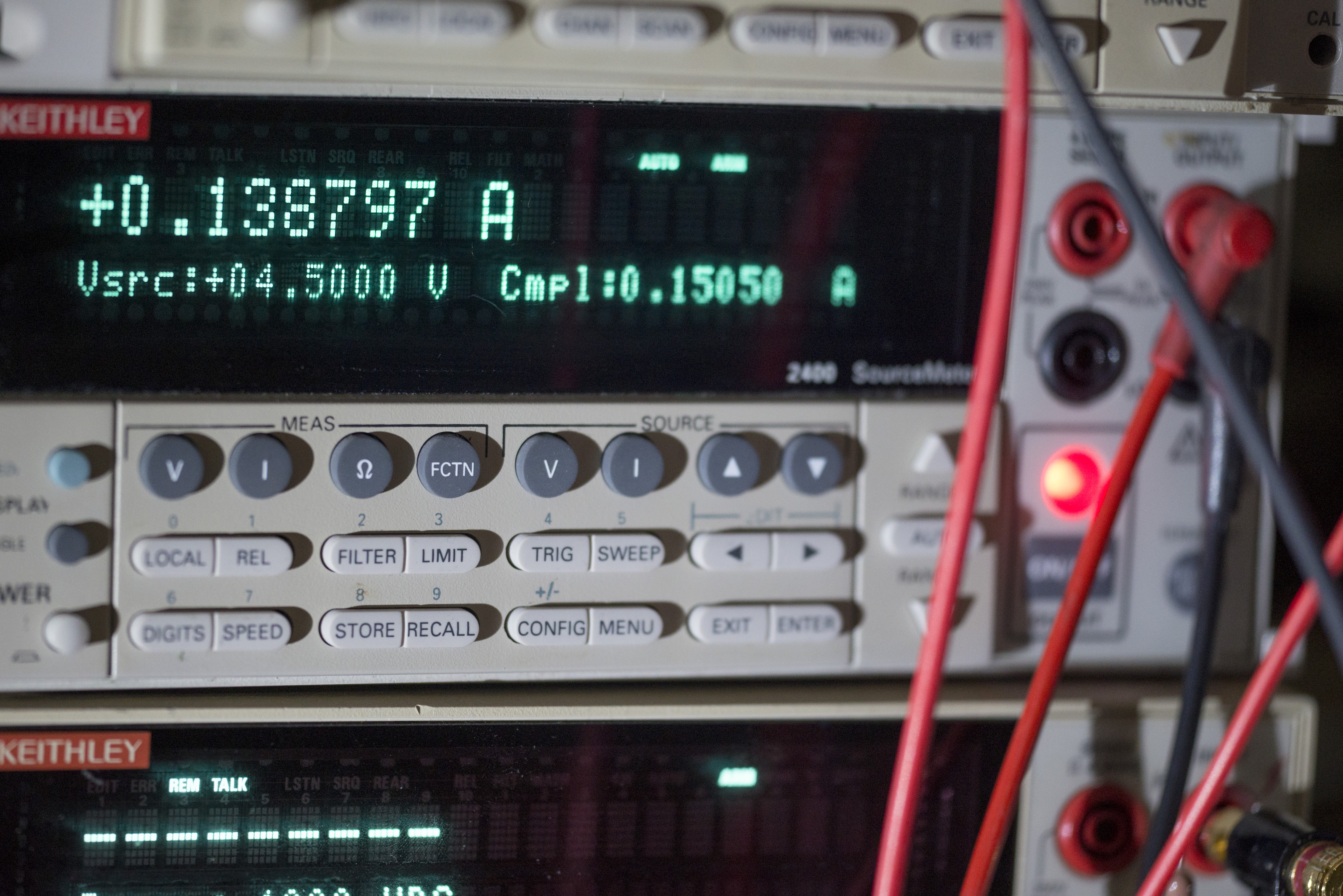
To do so, we used trusty Keithley 2400 SMU in source current mode with compliance at 4 VDC. Started with 140mA and raised up to 180mA (6.5VDC compliance voltage) for couple minutes to heat up filament.
If you use regular power supply, it’s best to use constant voltage mode, as when filament get hot, it’s resistance change, and you may end up
having more power provided to filament, and at one point it could reach point where filament would be damaged. Also do not shake or stress display with
hot filaments, as those tiny metal strings get some tension under power and could snap if exposed to excessive vibration.

Back to our display, now it become little better, but still not even close to fresh display.

There are current limiting resistors near each filament pin on PCB, stock resistors R405,R412 12.1 Ω and similar on other side. We can increase operation current by adding parallel resistors on top of original ones. I used three 22.1 Ω in 1206 size on top of each location.
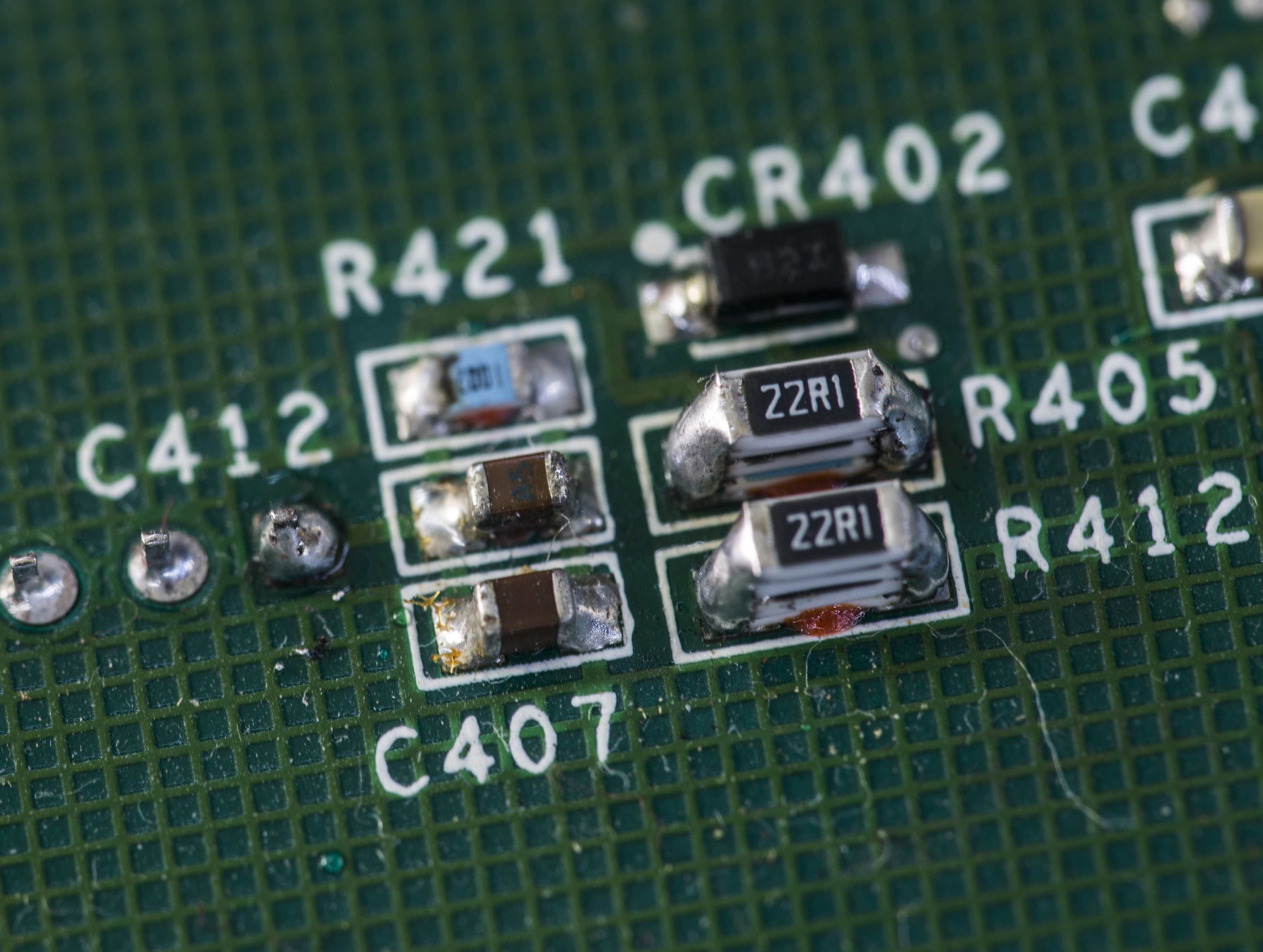

Good results achieved.

Now even with panel display can be read easily.
Of course this is temporary improvement, and after few years brightness will drop again, but it’s not much else to loose. After all VFDs are giving you that warm fuzzy feeling, and have awesome viewing angles and contrast.
Calibration
Calibration log to our reference HP 3458A using Time Electronics 9823 MFC as transfer standard:
Keithley Model 2000 - detected, S/N ???????, Version: A20  /A02
Environment temperature = 31.69 C, humidity = 35.40 RH, pressure = 1005.4830 hPa
HP 3458A detected
 TEMP? = 37.7 C
 Ambient temp = +26.9C
Calibrations count = 4
Calibration last date = 2016,07,21
:CAL:PROT:CODE 'KI002000'
Error status =  0,"No error"
CAL MFC error = -3.668 ppm
:CAL:PROT:DC:STEP3 9.999984
Error status =  0,"No error"
CAL MFC error = -18.421 ppm
:CAL:PROT:DC:STEP4 -9.999976
Error status =  0,"No error"
CAL MFC error = 5.642 ppm
:CAL:PROT:DC:STEP5 100.001513
Error status =  0,"No error"
:CAL:PROT:DC:STEP6 999.687270
Error status =  0,"No error"
:CAL:PROT:DC:STEP7 9999.419994
Error status =  0,"No error"
:CAL:PROT:DC:STEP8 99997.920833
Error status =  0,"No error"
:CAL:PROT:DC:STEP9 1000078.462000
Error status =  0,"No error"
:CAL:PROT:DC:STEP10 10010462.023333
Error status =  0,"No error"
:CAL:PROT:DC:STEP11 0.010000
Error status =  0,"No error"
:CAL:PROT:DC:STEP12 0.100000
Error status =  0,"No error"
:CAL:PROT:DC:STEP13 0.999994
Error status =  0,"No error"
K2000 CAL complete
Error status =  0,"No error"
Calibration takes about 20 minutes and automated using very rough python script. Sorry for crude code.
Performance verification
Performance test result after calibration:
| Test value | Reference meter reading | K2000 DUT reading | Deviation | K2000 spec 1Y |
|---|---|---|---|---|
| Zero V | 4.491791632E-07 VDC | 4.524117620E-06 VDC | +4.07 µV | |
| 10 mVDC | 9.999771025E-03 VDC | 1.000227407E-02 VDC | +250.247 ppm | ± 50+35 |
| 100 mVDC | 9.999966408E-02 VDC | 1.000016543E-01 VDC | +19.902 ppm | ± 50+35 |
| 1 VDC | 9.999992243E-01 VDC | 1.000006293E+00 VDC | +7.069 ppm | ± 30+7 |
| 10 VDC | 9.999985257E+00 VDC | 9.999995660E+00 VDC | +1.040 ppm | ± 30+5 |
| -10 VDC | -9.9998207 VDC | -9.99982 VDC | -0.07 ppm | ± 30+5 |
| 100 VDC | 1.000009096E+02 VDC | 1.000001532E+02 VDC | -7.564 ppm | ± 45+6 |
| 1000 VDC | 1.000003997E+03 VDC | 1.000006193E+03 VDC | +2.197 ppm | ± 45+6 |
| 10 Ω | 10.00018 Ω | 9.9970 Ω | -317.99 ppm | ± 100+40 |
| 100 Ω | 99.96888 Ω | 99.9672 Ω | -16.81 ppm | ± 100+40 |
| 1 KΩ | 999.6869 Ω | 999.688 Ω | +1.1 ppm | ± 100+10 |
| 10 KΩ | 9999.420 Ω | 9999.45 Ω | +3.0 ppm | ± 100+10 |
| 100 KΩ | 99997.82 Ω | 99997.6 Ω | -2.2 ppm | ± 100+10 |
| 1 MΩ | 1000076.1 Ω | 1000046 Ω | -30.1 ppm | ± 100+10 |
| 10 MΩ | 10010629 Ω | 10.01095 MΩ | +32.1 ppm | ± 400+10 |
| 100 µADC | 100.01537E-6 ADC | 100.01E-6 ADC | -54 ppm | ± 500+80 |
| 1 mADC | 1.0000046E-3 ADC | 1.00002E-3 ADC | +15.4 ppm | ± 500+80 |
| 10 mADC | 10.000132E-3 ADC | 10.00020E-3 ADC | +6.8 ppm | ± 500+80 |
| 100 mADC | 99.99881E-3 ADC | 99.9984E-3 ADC | -4.1 ppm | ±500+800 |
| 1 ADC | 0.9999221 ADC | 0.999919 ADC | -3.1 ppm | ±1200+40 |
| 100mAAC (60Hz) | 100.0059E-3 AAC | 99.94E-3 AAC | -658.9 ppm | ±1000+400 |
| 10VAC (60Hz) | 10.00084 VAC | 9.9993 VAC | -154 ppm | ±500+300 |
| 60Hz | 59.99632 Hz | 59.99627 Hz | -0.83 ppm | ±100 |
DCV Noise evaluation at shorted inputs
Restoration summary
Meter is returned to operation state and passed calibration with good margins compared to HP 3458A, so was an interesting project to work with, considering the relatively affordable pricing on Keithley 2000’s.
Hopefully we will hear more about this unit in future by new owner.
Modified: Sept. 2, 2023, 4:42 p.m.
References
- Kuba blog : Keithley 2000 bench multimeter repair part2
- Kuba blog : Keithley 2000 bench multimeter repair part1
- EEVBlog : Model 2015 Firmware
- EEVBlog : Repair 2000 thread
- EEVBlog : Repair 2000, leaked caps thread
- EEVBlog : xDevs's Repair 2000 thread
- EEVBlog : Wacky ohms repair thread
- Keithley 2000 DMM Repair (Andy Bardagjy)
- Keithley 2000 repair (dEdIUS)
- Reversed schematics from jhzyou 126.com
- EEVBlog : Repair of Keithley 2000, faulty TF-245