- Recommended calibration methods
- xDevs.com 792X Calibration procedure – using solid-state reference
- xDevs.com 792X Calibration procedure – using Quantum JVS
- Calibration results and performance tracking
- Conclusion
Intro
![]()
![]()
![]()
![]()
![]()
![]()
This article provides calibration method, with verification procedure for prototype xDevs.com 10V DC Voltage Reference, assembled in standard Fluke 792A Power Pack chassis. Reference has permanent battery backup power with integrated charger, to maintain internal oven temperature and prevent output power cycle hysteresis effect.
Charger/power supply is originally manufactured Fluke 792A Power Pack, only difference is added ultra-stable 10V reference module, mounted in own shielded enclosure, internal to the power pack. Reference is based on proven Linear LTZ1000A super-zener design, build details are shown in this article. Reference was running on constant power since January 2018.
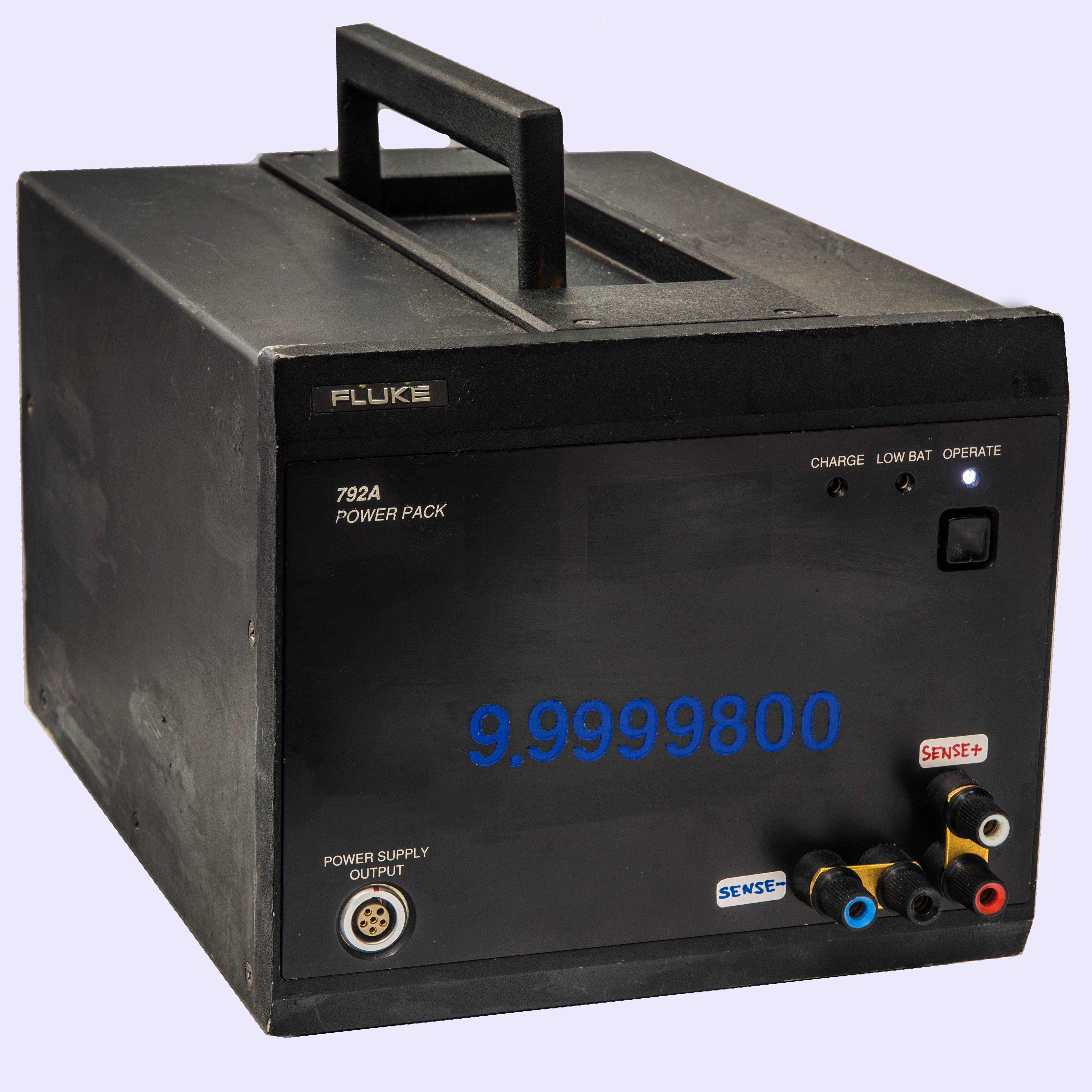


Front panel of Fluke 792A Power Pack was modified to install additional four 5-way low-thermal copper connectors. These connectors provide 4-wire +10 VDC output. Both current and sense terminals are present, and DC reference capable sourcing or sinking currents up to 20 mA, while remote sense helps maintaining output accuracy within 1 µV/V or better.
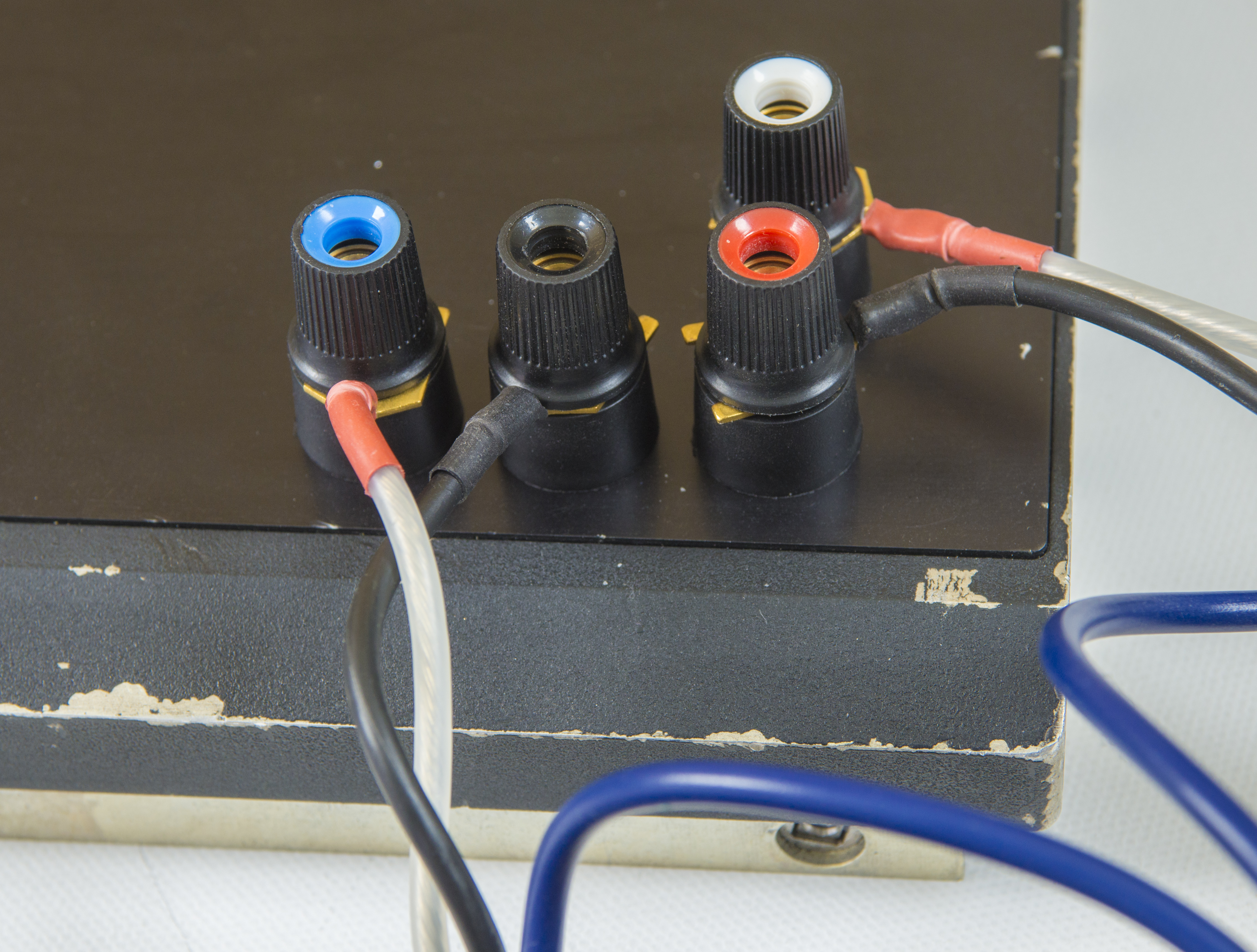
Output definition:
- RED terminal – FORCE HIGH +10V
- WHITE terminal – SENSE HIGH +10V
- BLACK terminal – FORCE LOW / COMMON
- BLUE terminal – SENSE LOW
*For high-impedance loads, such as 8½-digit DMM or Fluke 5720A calibrator output terminals sense must be shorted with force, using heavy gauge copper bars.
Bars are included with standard when it’s shipped to calibration.*
Disclaimer
Redistribution and use of this article, any part of it or any images or files referenced in it, in source and binary forms, with or without modification, are permitted provided that the following conditions are met:
- Redistributions of article must retain the above copyright notice, this list of conditions, link to this page (https://xdevs.com/article/792x_cal/) and the following disclaimer.
- Redistributions of files in binary form must reproduce the above copyright notice, this list of conditions, link to this page (https://xdevs.com/article/792x_cal/), and the following disclaimer in the documentation and/or other materials provided with the distribution, for example Readme file.
All information posted here is hosted just for education purposes and provided AS IS. In no event shall the author, xDevs.com site, or any other 3rd party be liable for any special, direct, indirect, or consequential damages or any damages whatsoever resulting from loss of use, data or profits, whether in an action of contract, negligence or other tortuous action, arising out of or in connection with the use or performance of information published here.
If you willing to contribute or add your experience regarding instrument repairs or provide extra information, you can do so following these simple instructions.
Specifications define
Reference is portable and designed to fit into transport case, such as Pelican 0340 or similar. It contains all necessary hardware and only require AC 110/230 VAC mains power for continuous operation.
| xDevs.com/Fluke 792X | Specification |
| DC Output | 4-wire with dedicated sense and force terminals |
| Nominal output | +10.00000 VDC |
| Initial accuracy | ±2 µV/V |
| Annual stability | ±2 µV/V, ±1 °C from calibration temperature |
| Transfer stability | ±0.3 ppm, ±0.5 °C for 1 hour |
| Temperature coefficient | less than 0.1 ppm/°C |
| Calibration temperature | +23 ±1 °C |
| Adjustment range | None, fixed output only |
| Overload protection | indefinite with shorted output |
| Maximum output current | ± 30 mA , both source or sink mode |
| Loading for 1 µV/V error | 100 µA with sense-force short on output or 20mA with remote sense |
| Battery type | 4 × 6V Panasonic sealed VRLA 4.5 Wh |
| Battery life | at least 72 hours with 792A power output in standby |
| Dimensions | 18 × 22 × 31 cm |
| Weight | 9.1 kg (20 lbs) |
| Operation temperature | +18 °C to +28 °C |
Battery operation
For most critical use cases, such as reference calibration or long-scale DMM verification xDevs.com 792X supports fully floating operation with internal battery power. Floating battery operation prevents ground loop currents and ensure lowest possible noise for +10 V output. Battery power is also important enabling factor for calibration against cryocooled Quantum Voltage Standards, such as NIST PJVS.
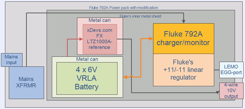
To maintain battery charge unit has original Fluke 792A power pack charger. Unit provides two modes of operation, exactly like standard Fluke 792A Power Pack. Linear power supply can provide ±11 VDC output at the LEMO port for use with Fluke 792A Transfer unit. While unit is in OPERATE (WHITE LED is ON) – mains power is disconnected by relay from the battery charging circuit. If battery charge level too low, WHITE “OPERATE” LED will be turned off and “LOW BATT” RED LED will be activated instead. If this happens, connect AC mains power AND switch unit to STANDBY MODE.
When unit is switched to STANDBY mains power will be connected to charger, and batteries will be charged until full. Low-Dropout Regulators provide stabilized power for the +/-11 V output supply only when unit is in OPERATE. However LTZ1000A-based reference is powered directly from the internal batteries and POWERED ALWAYS, disregarding what is the mode of 792A power output.
Caution! There is no low battery shut-down function in xDevs.com 792X reference. If unit left on battery power or OPERATE mode (WHITE LED ON) for more than 72 hours, batteries will be depleted. There is no automatic switching to charging, even if mains power is connected!
Do not leave standard unpowered after LOW BATT red LED is active. This condition will invalidate +10 V output calibration history and cause catastrophic damage the unit and require battery replacement!
Recommended calibration methods
This section outline output calibration procedure. Procedures use direct comparison between xDevs.com 792X, called later the Unit Under Test (UUT), and a certified and traceably calibrated Fluke 732A/B/C or Datron 4910 standard called Standard Reference (SR) to calibrate the 10V output. There are no means for output adjustments for xDevs.com 792X reference and calibration include measurement comparison only.
Table below shows complete list of the equipment you will need to calibrate the 792X output.
| Equipment required | Manufacturer / Model number | Calibration period |
| DC Nanovoltmeter | Keithley 2182A | Within 1 year from last calibration |
| DC Nanovoltmeter (alternative) | Agilent or Keysight 34420A | Within 1 year from last calibration |
| Standard reference | Fluke 732A or 732B or 732C | +10 V output, Less than 1 µV/V uncertainty, 95% |
| Standard reference (alternative) | Datron 4910 or 4911 | +10 V output, Less than 1 µV/V uncertainty, 95% |
| Standard reference (alternative) | Fluke 7004N or 734A/C | +10 V output, Less than 1 µV/V uncertainty, 95% |
| Low thermal EMF cable | Fluke 5440A-7002 2 terminal + guard | Alternative pure copper spade lug cable is OK |
| Low thermal EMF cable | Fluke 5440A-7002 2 terminal + guard | Alternative pure copper spade lug cable is OK |
Before proceed, leave xDevs.com 792X UUT and Fluke 732 SR powered on with the BAT switch set to [|] and the standard plugged into AC mains line power for at least 24 hours. Make sure UUT is in STANDBY mode, indicated by left RED LED. This ensure stabilized oven temperature in standards and fully charge the internal battery.
xDevs.com 792X is shipped with two heavy gauge copper bars between SENSE and FORCE terminals. Do not remove the shorts for calibration procedures.
Make sure both standards are located away from any equipment that generate heat or airflow, such as calibrators, DMMs or lab power supplies.
Ensure absence of forced airflow or drafts near both UUT and SR output terminals to avoid excessive noise due to thermal EMF.
Avoid the use of ordinary, nickel-plated, banana plugs for equipment interconnections. These will cause errors that negatively affect calibration accuracy. Use only copper connectors that have small thermal emf’s with respect to copper posts on standards.
Use the Fluke 5440A-7002 Low Thermal EMF Cable Set or alternative low-thermal EMF wiring. Use #24 AWG or larger bare copper Teflon®-insulated connecting wires. It is preferable to use shielded, twisted pair cable. Avoid splices or any adapters between standards. Use low thermal emf copper spade lugs. Crimp the lug onto the wire and solder the connection.
Loosen the top of the binding post, insert the lug, and tighten the binding post on the lug with fingers only.
xDevs.com 792X Calibration procedure – using solid-state reference
Inspect standards, ensure there is no physical damage. Preserve packaging, and let standard sit for at least 24 hours after transport. Mains power should be provided to unit, and “CHARGE” LED should lit red.
Keep included shorting bar between SENSE and FORCE terminals on 792X standard connected at all times.
1. Disconnect mains power cable from xDevs.com 792X UUT. Switch power button until white “OPERATE” LED is activated.
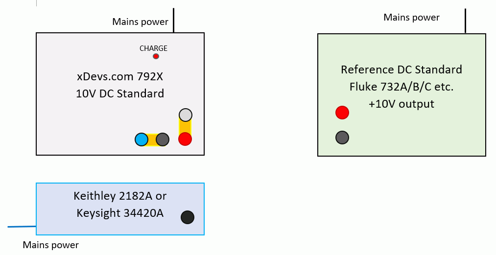
2. Connect calibrated Fluke 732 SR and DC Nanovoltmeter as shown in figure below. Use most sensitive range without overflow on the nanovoltmeter.
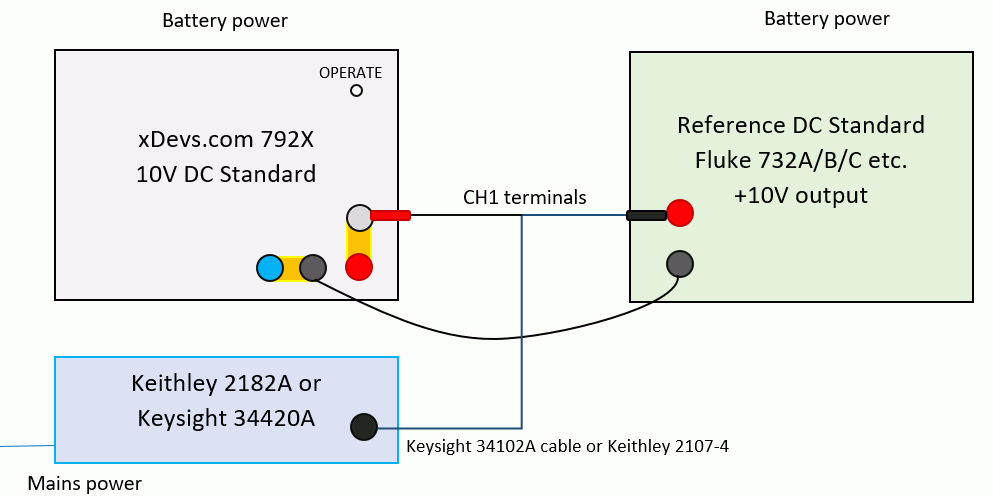
3. Monitor the meter readings and allow the thermals to stabilize. 10 minutes is reasonable time frame for this operation.
4. Average the meter readings over a period of at least 1 minute. Record these values. Recommended to take median of 5 last readings.
5. Reverse the HI (RED) and LO (BLACK) (positive and negative) leads on the meter.
6. Monitor the meter readings and allow the thermals to stabilize. 10 minutes is reasonable time frame for this operation.
7. Average the meter readings over a period of at least 1 minute. Record these values. Recommended to take median of 5 last readings.
8. Subtract the readings from step 4 from the readings from step 7 and divide this result by 2. This is the difference EMF between the two devices. The value could be negative.
9. Add the value from step 8 to the value from the certificate for the calibrated Fluke 732 (SR). This is the value of the xDevs.com 792X UUT.
10. Disconnect all test equipment. Connected mains power cable back to xDevs.com 792X and 732 standard. Make sure to switch xDevs.com 792X to CHARGE mode with RED led on.
Calculate expanded uncertainty, using DC Nanovoltmeter results, calibration reports and instruments specifications, as outlined by ISO 17025 and GUM.
Keep xDevs.com 792X standard plugged to mains 110 VAC power AND red CHARGE LED activated until it’s ready to ship.
xDevs.com 792X Calibration procedure – using Quantum JVS
UUT can be calibrated directly against SI Volt realization by JVS system, when operated floating and has output noise and stability similar to industry standard Fluke 732B.
1. Disconnect mains power cable from xDevs.com 792X UUT. Switch power button until white “OPERATE” LED is activated.
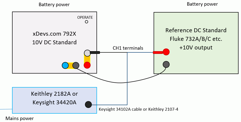
2. Connect JVS array output LO and UUT LO together with low thermal EMF cable.
3. Connect DC Nanovoltmeter as shown in figure below, CH1 between JVS HI and 792X UUT HI.
4. Program JVS output to +10V output. Note meter readings and adjust JVS output for smallest differential on 10mV range.
5. Monitor the meter readings and allow the thermals to stabilize. 10 minutes is reasonable time frame for this operation.
6. Average the meter readings over a period of at least 1 minute. Record these values. Recommended to take median of 5 last readings.
7. Reverse the HI and LO (positive and negative) leads on the meter.
8. Monitor the meter readings and allow the thermals to stabilize. 10 minutes is reasonable time frame for this operation.
9. Average the meter readings over a period of at least 1 minute. Record these values. Recommended to take median of 5 last readings.
10. Subtract the readings from step 6 from the readings from step 9 and divide this result by 2. This is the difference between the two devices. The value could be negative.
11. Correct for thermal EMF differential from JVS system. Calculate final value of the xDevs.com 792X UUT.
12. Disconnect all test equipment outputs. Connected mains power cable to xDevs.com 792X. Make sure to switch xDevs.com 792X to CHARGE mode with RED led on.
Calculate expanded uncertainty, using DC Nanovoltmeter data, calibration reports and instruments specifications, as outlined by ISO 17025 and GUM.
Now calibration of the UUT xDevs.com 792X is complete.
Final assembled reference, ready for use as working standard
Here is finally assembled DC Voltage reference, reusing Fluke 792A Power Pack to provide battery power to the xDevs.com FX 10V module, as well as charge battery. DC reference outputs are full 4-wire kelvin connection with Low Thermal posts, with current source/sink capability over 20 mA. In normal operation SENSE HI and SENSE LO posts should be shorted to CURR HI / LO posts to close the output feedback loop.
Charger / power supply for 792A AC/DC transfer unit is also allowed independently, using original LEMO port and cable.

Back and side of the unit as fully shielded, just like original Fluke 792A, no alterations made on these sides.


This DC reference is constantly powered after assembly on since January 2018.
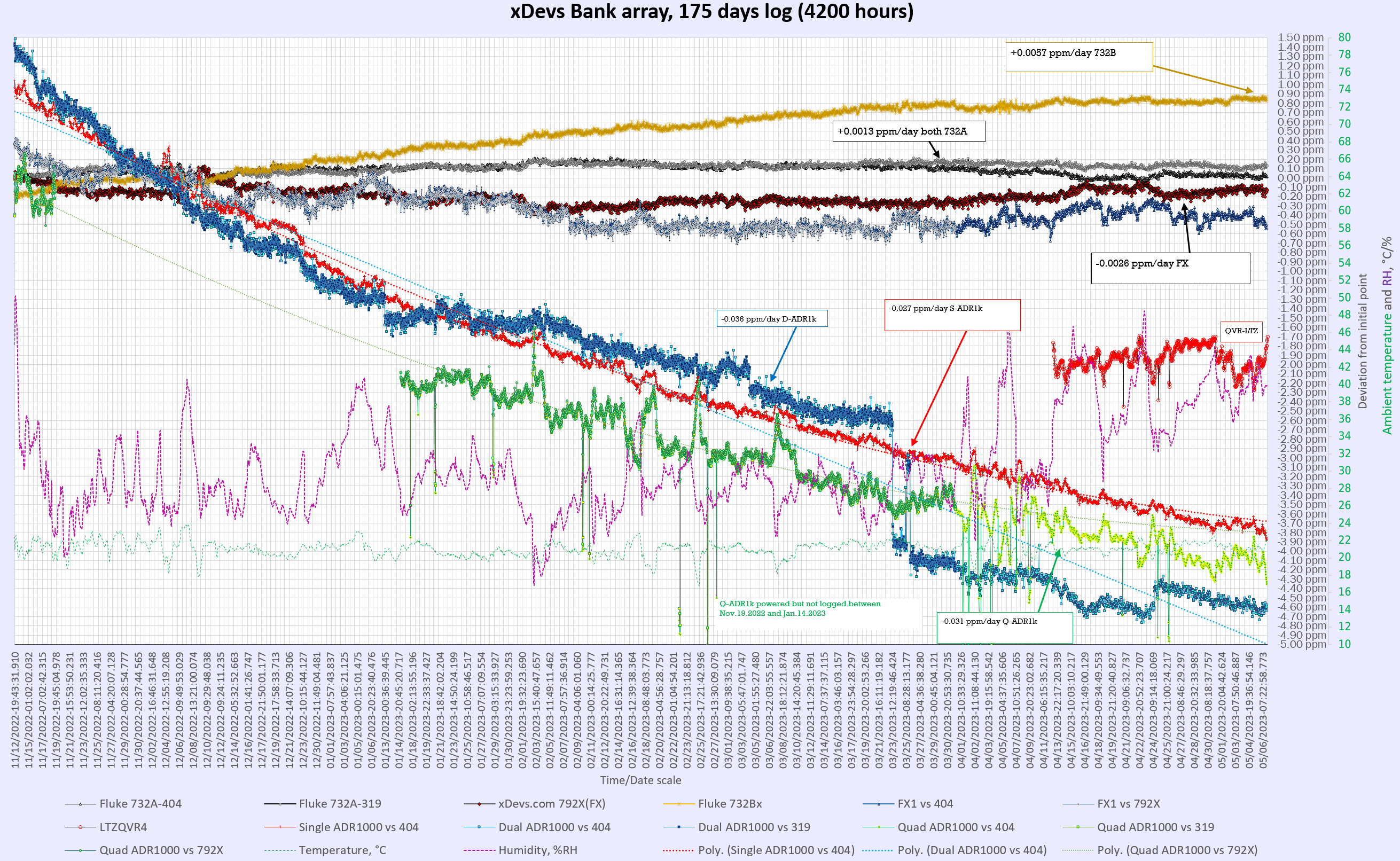
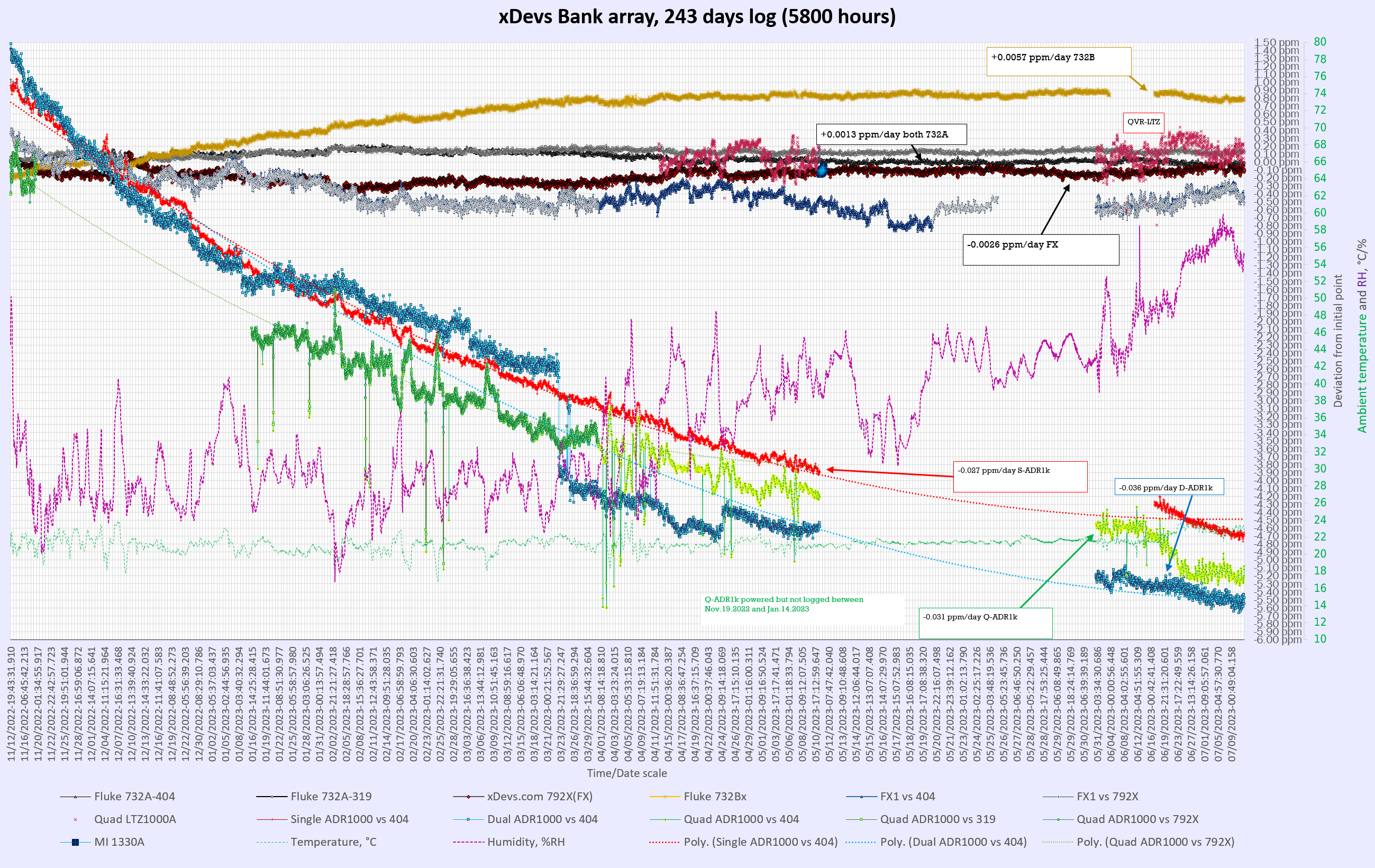
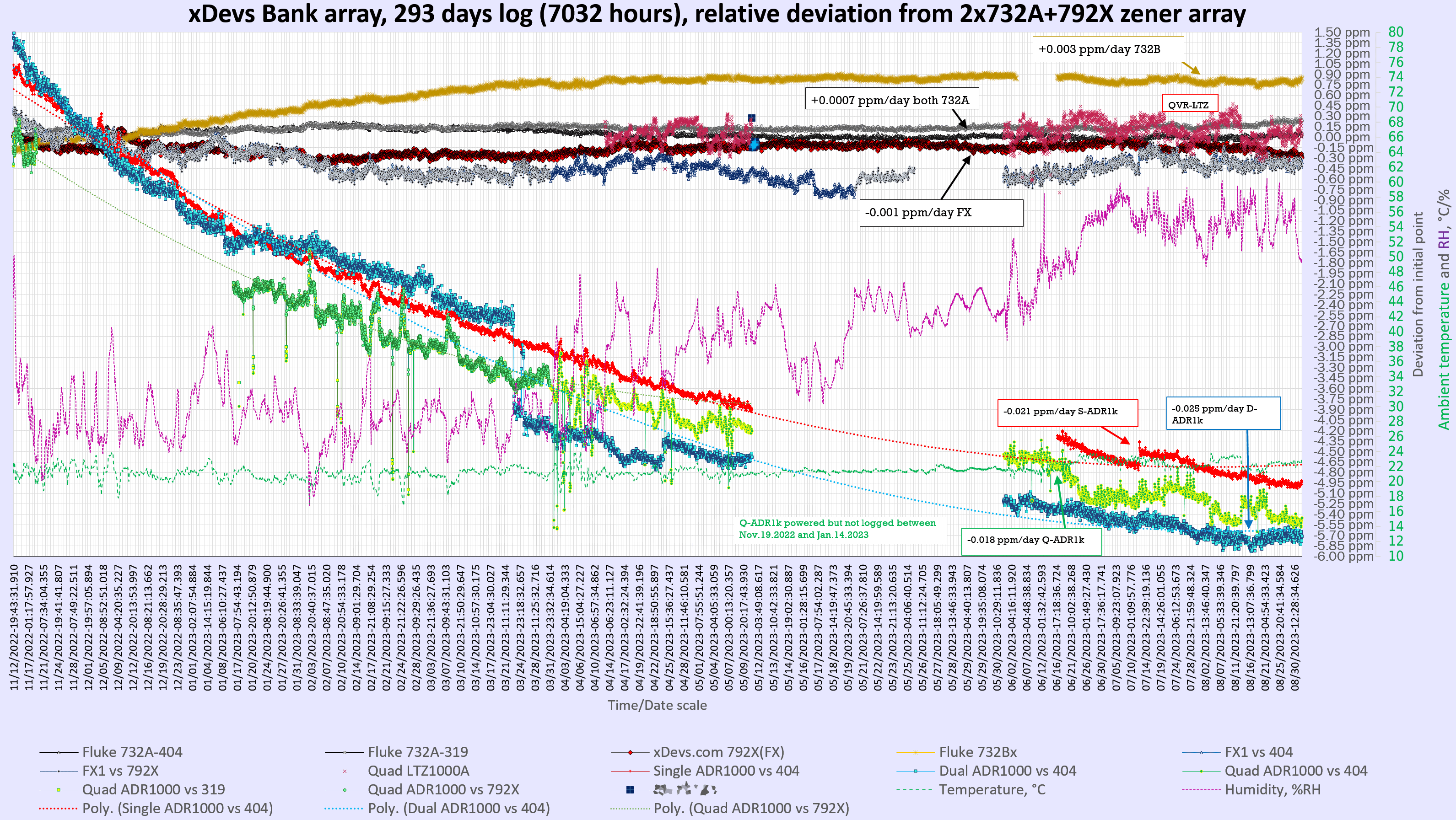
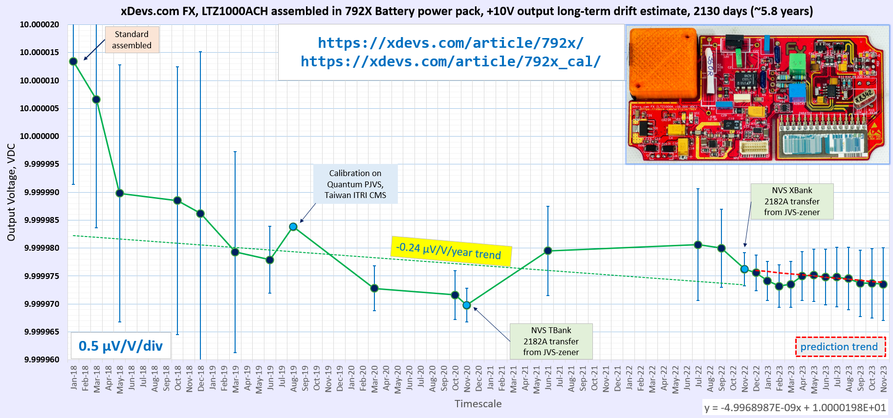
Calibration results and performance tracking
This reference was calibrated by Taiwan’s National Measurements Institute in August 2019 . NIST SRI6000 PJVS system was used as a primary traceable reference during that key calibration.
Calibration report for xDevs.com 792× 10V DC Voltage Reference, August 8 2019, Taiwan NMI
Calibration report for xDevs.com 792× 10V DC Voltage Reference, March 3 2020, TMI Lab, FL, USA
Accredited external calibration history so far:
| xDevs.com 792X | Calibration Date | Assigned value | Uncertainty | Shift | Shift/year | Days |
| TW NMI calibration (NIST PJVS Quantum system) | 08/08/2019 | 9.9999838 VDC | 0.03 µV/V | -1.82 µV/V | -1.16 µV/V | +573 |
| TMI calibration | 03/03/2020 | 9.9999751 VDC | 0.39 µV/V | -2.69 µV/V | -1.26 µV/V | +208 |
Here we have all list of traceable calibrations to other references of similar grade, and estimate annual stability of finished 792X project.
| Calibration date | Method | Measurement result | Uncertainty | Conditions | Accredited | Δ to predicted |
|---|---|---|---|---|---|---|
| January 2018 | Direct 3458A+3458B, K2002 measurement | +10.0000134 V | ±2.20 µV/V | Battery power | No | No data |
| March 2018 | Direct 3458B | +10.0000066 V | ±2.30 µV/V | Battery power | No | No data |
| May 2018 | Direct 3458A | +9.99998983 V | ±2.30 µV/V | Battery power | No | No data |
| October 2018 | Direct 3458B | +9.9999885 V | ±2.40 µV/V | Battery power | No | No data |
| December 2018 | Direct 3458A, corrected | +9.9999862 V | ±2.90 µV/V | Battery power | No | No data |
| March 2019 | Direct 3458s,2002 | +9.9999793 V | ±1.80 µV/V | AC power | No | No data |
| June 2019 | K155 vs F732B SI | +9.9999779 V | ±0.60 µV/V | Battery power | No | No data |
| 8 August 2019 | PJVS SRI6000 transfer @ CMS ITRI | +9.99998382 V | ±0.03 µV/V | Battery power | NMI | Zero reference |
| March 2020 | HP34420A vs F732B | +9.9999728 V | ±0.40 µV/V | Battery power | Yes | No data |
| October 2020 | 3458A transfer from 732B | +9.9999716 V | ±0.44 µV/V | Battery power | No | No data |
| November 2020 | JJ-referenced D4910 array | +9.9999698 V | ±0.30 µV/V | Battery power | No | 1st reference |
| September 2021 | NLab VBank system | +9.9999800 V | ±0.70 µV/V | AC Power | No | No data |
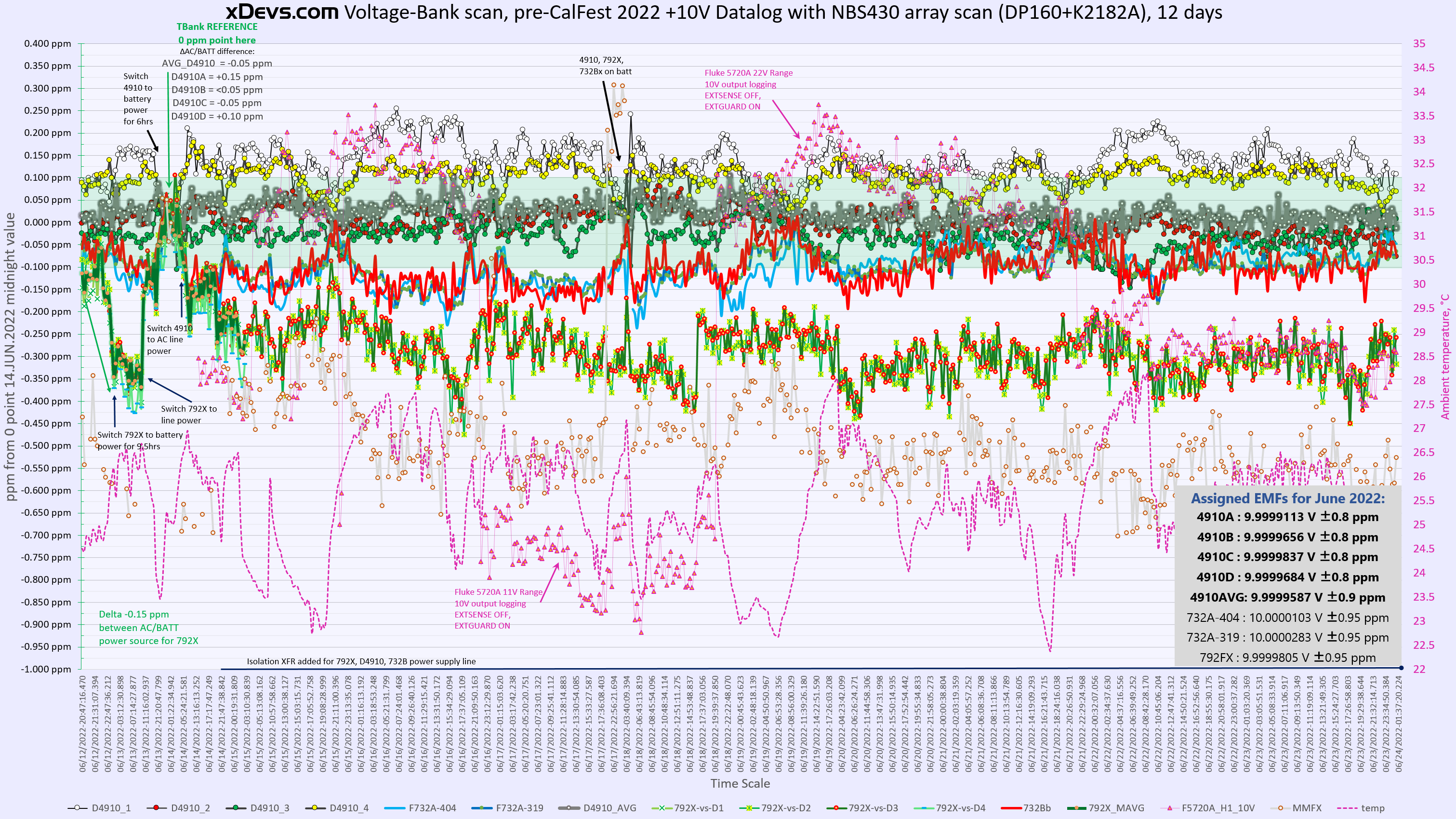
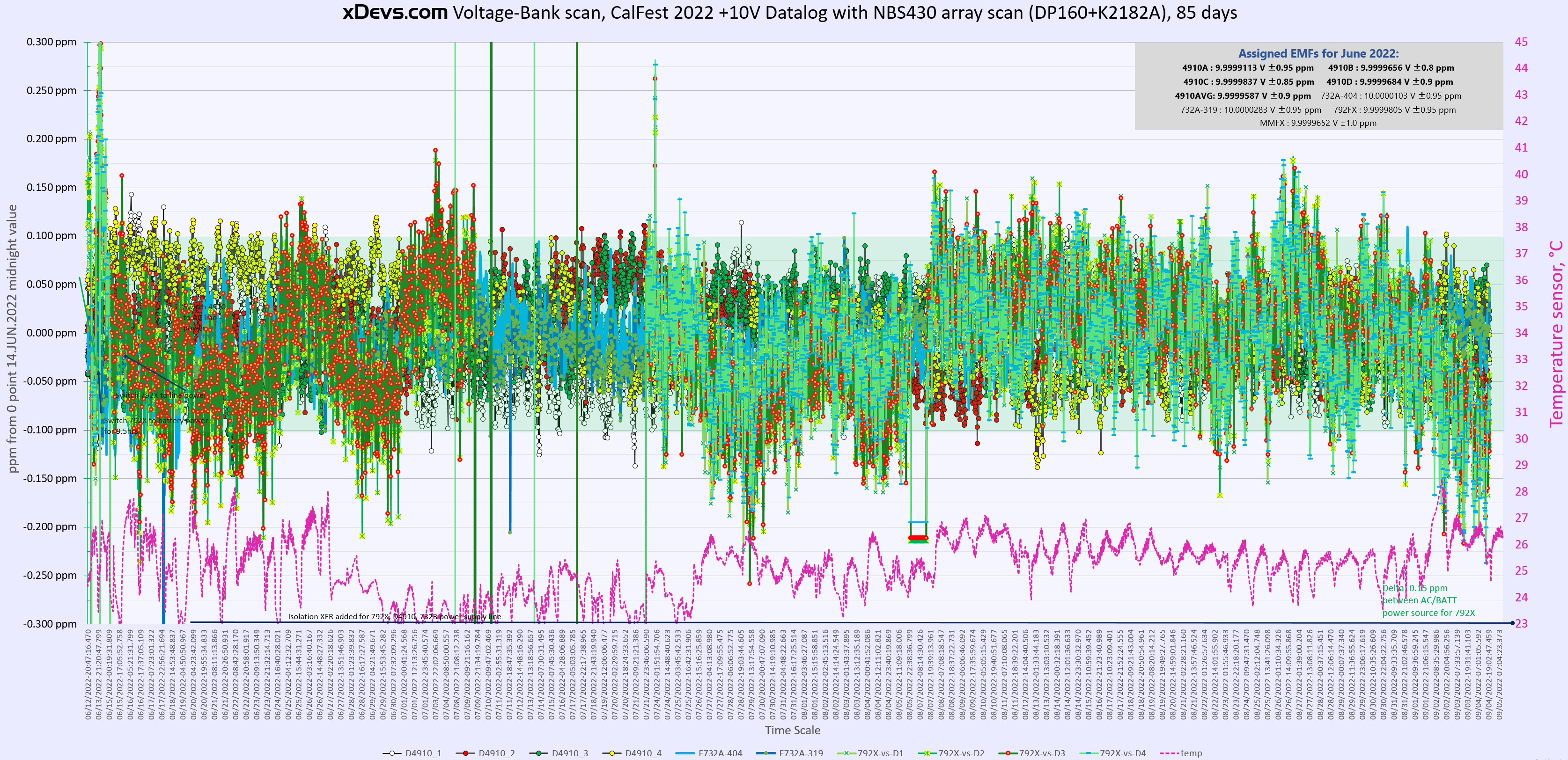
| June 2022 | D4910 TBank system | +9.9999795 V | ±0.80 µV/V | Battery Power | No | No data |
| July 2022 | D4910 TBank | +9.9999806 V | ±1.00 µV/V | Battery Power | No | No data |
| November 2022 | JJ-referenced D4910 XBank | +9.99997612 V | ±0.30 µV/V | Line Power | No | 2nd reference, +0.42 µV/V |
| December 2022 | X-Bank array + nVM | +9.99997557 V | ±0.32 µV/V | Line power | No | 0.04 µV/V |
| January 2023 | X-Bank array + nVM | +9.99997414 V | ±0.35 µV/V | Line power | No | 0.16 µV/V |
| February 2023 | X-Bank array + nVM | +9.99997320 V | ±0.38 µV/V | Line power | No | 0.24 µV/V |
| March 2023 | X-Bank array + nVM | +9.99997353 V | ±0.41 µV/V | Line power | No | 0.18 µV/V |
| April 2023 | X-Bank array + nVM | +9.99997500 V | ±0.44 µV/V | Line power | No | 0.02 µV/V |
| May 2023 | X-Bank array + nVM | +9.99997514 V | ±0.47 µV/V | Line power | No | -0.01 µV/V |
| June 2023 | X-Bank array + nVM | +9.99997482 V | ±0.50 µV/V | Line power | No | 0.00 µV/V |
| July 2023 | X-Bank array + nVM | +9.99997481 V | ±0.53 µV/V | Line power | No | -0.01 µV/V |
| August 2023 | X-Bank array + nVM | +9.99997453 V | ±0.56 µV/V | Line power | No | -0.01 µV/V |
| September 2023 | X-Bank array + nVM | +9.99997369 V | ±0.59 µV/V | Line power | No | 0.05 µV/V |
| October 2023 | X-Bank array + nVM | +9.99997373 V | ±0.62 µV/V | Line power | No | 0.03 µV/V |
| November 2023 | X-Bank array + nVM | +9.99997355 V | ±0.65 µV/V | Line power | No | 0.03 µV/V |
| June 2024 | X-Bank array + nVM | +9.9999762 V | ±0.8 µV/V | Line power | No | 0.? µV/V |
| 25 October 2024 | JJ-referenced D4910 XBank | +9.99997031 V | ±0.3 µV/V | Line power | No | 3rd reference, 0.? µV/V |
Drift of this custom LTZ1000A-based referenced in 1181 days between two JVS-referenced points in 25 October 2024 and 8 August 2019 is -1.351 µV/V. This translates into voltage drop at rate -0.259 µV/V/year, which is pretty good for DIY single-device zener reference that is being constantly powered.
Such long-term drift study also highlights importance of periodic calibrations with very good uncertainty, ideally directly referenced to quantum standards such as Josephson Voltage System with minimal amount of intermediate transfer standards or transportation. Table and chart in this section represent only condensed key summary of all the measurements and long-term data captured by xDevs.com members and in-house automation software. We have gigabytes of data points captured on this and other standards including commercial units like Fluke 732A/B, Datron 491x and others. Due to magnitude of sources used and complexity of such large dataset analysis with logistic challenges this data it is not available to public at this time.
One also can notice important evolution of our in-house voltage measurement and monitoring capability improvements over the years time span, which is also reflected in improved uncertainty of the points. Current setup is built around array of various zener standard, DataProof 160A low-thermal scanner , Keithley 2182A nanovoltmeter and in-house software implementing modified algorithm measuring matrix opposite polarity of each zener cell, heavily inspired by NIST/NBS Technical Note 430. All measurements are done in both polarities to cancel thermal EMF errors. Use of dedicated nanovoltmeter on most sensitive range instead of long-scale DMM such as HP3458A helps to remove the contribution of the meter’s tempco and noise from zener voltage result.
Conclusion
In this article we looked at calibration procedure for LTZ1000A-based reference and reviewed performance verification results of this custom standard. Performance of device was confirmed expectations and we’ll keep monitoring long-term drift in future to maintain low uncertainty of xDevs.com Volt, together with commercial references such as Fluke 732A and 732B.
Discussion is very welcome thru comment section or at our own IRC chat server: irc.xdevs.com (port six-zero-one-zero; channel: #xDevs.com). Web-interface for access mirrored on this page. If you have information and performance reports of various standards not mentioned or listed in this article, feel free to provide them and we will showcase them on site.
Projects like this are born from passion and a desire to share how things work. Education is the foundation of a healthy society - especially important in today's volatile world. xDevs began as a personal project notepad in Kherson, Ukraine back in 2008 and has grown with support of passionate readers just like you. There are no (and never will be) any ads, sponsors or shareholders behind xDevs.com, just a commitment to inspire and help learning. If you are in a position to help others like us, please consider supporting xDevs.com’s home-country Ukraine in its defense of freedom to speak, freedom to live in peace and freedom to choose their way. You can use official site to support Ukraine – United24 or Help99. Every cent counts.
Modified: Jan. 1, 2026, 4:59 a.m.