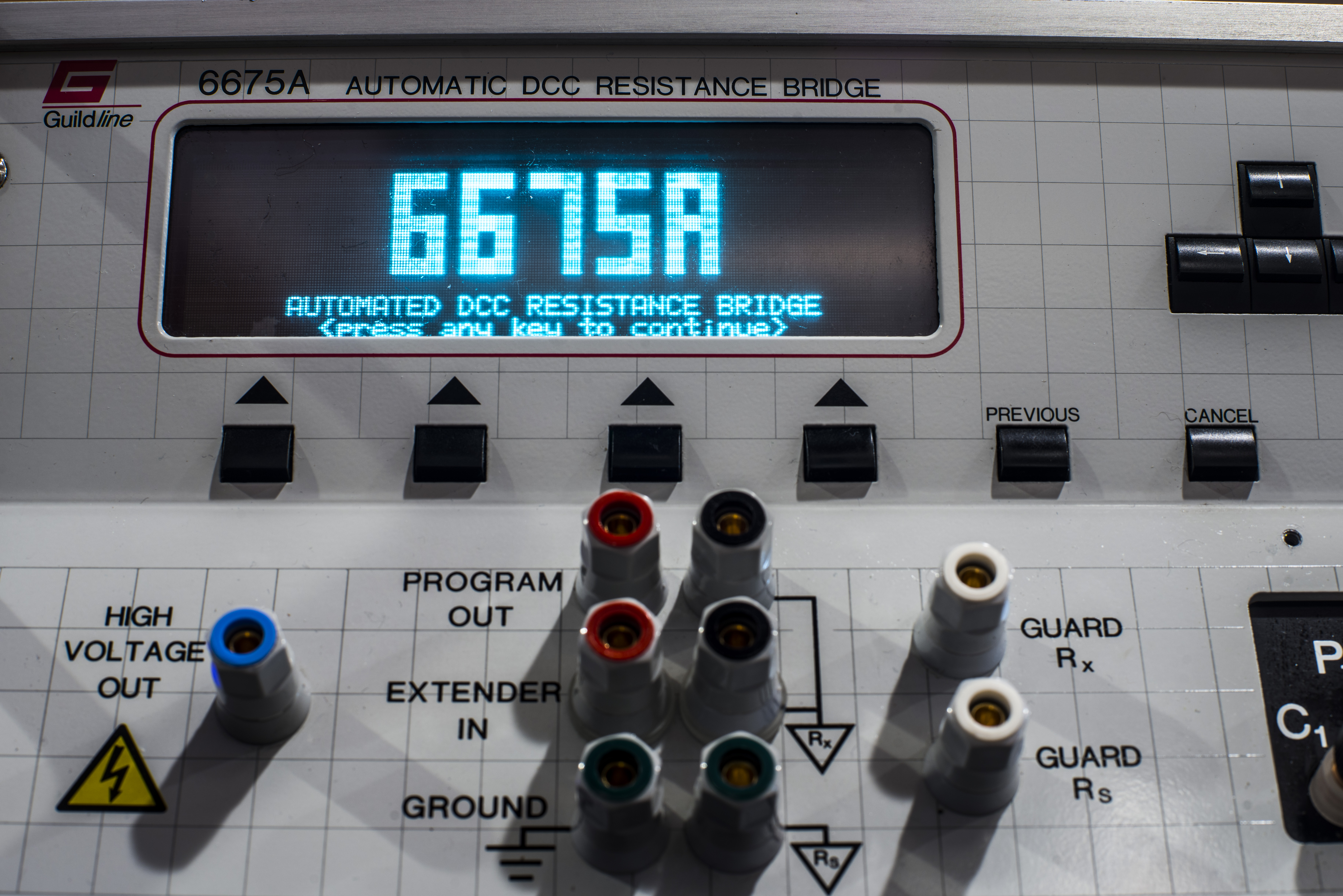
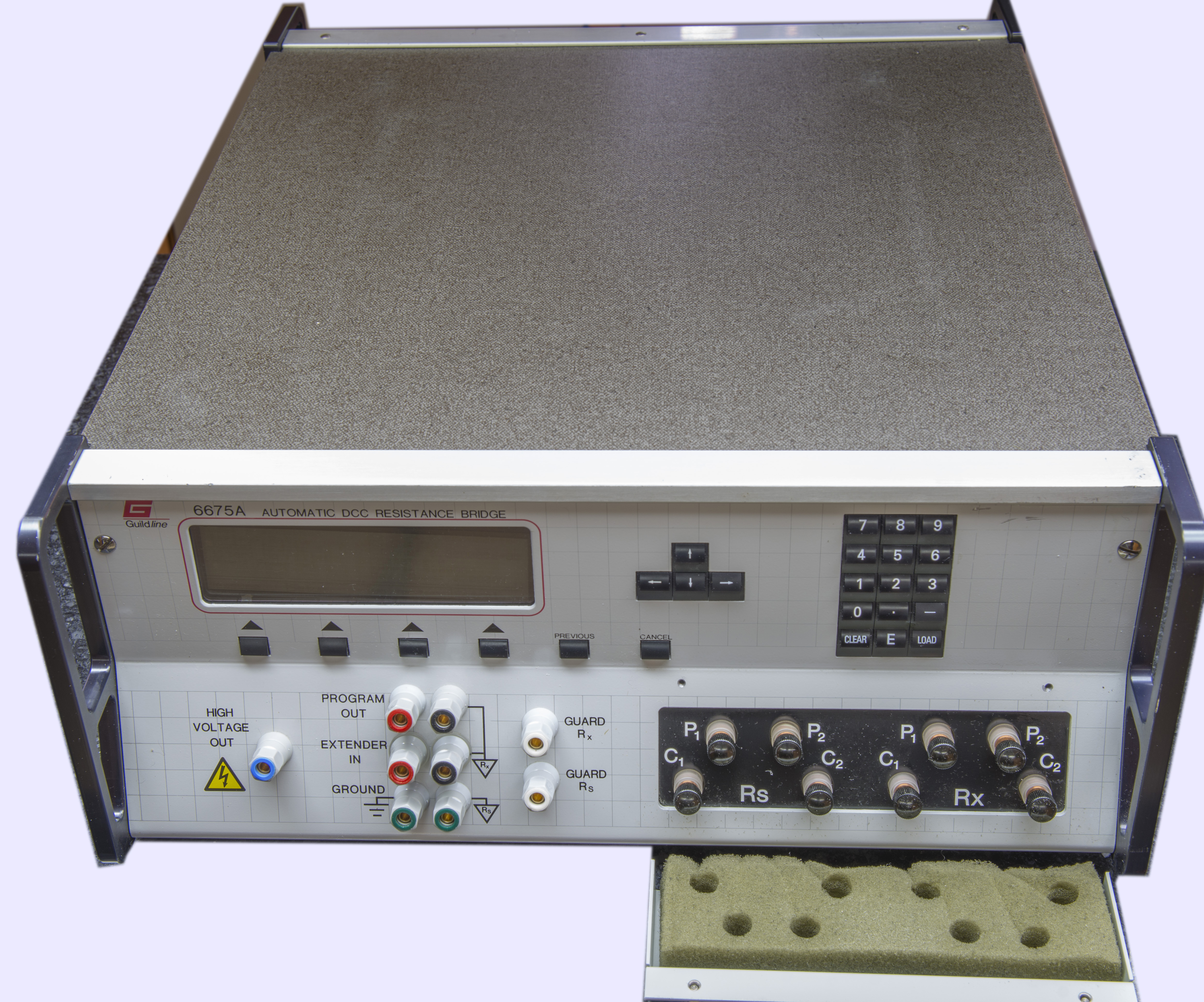
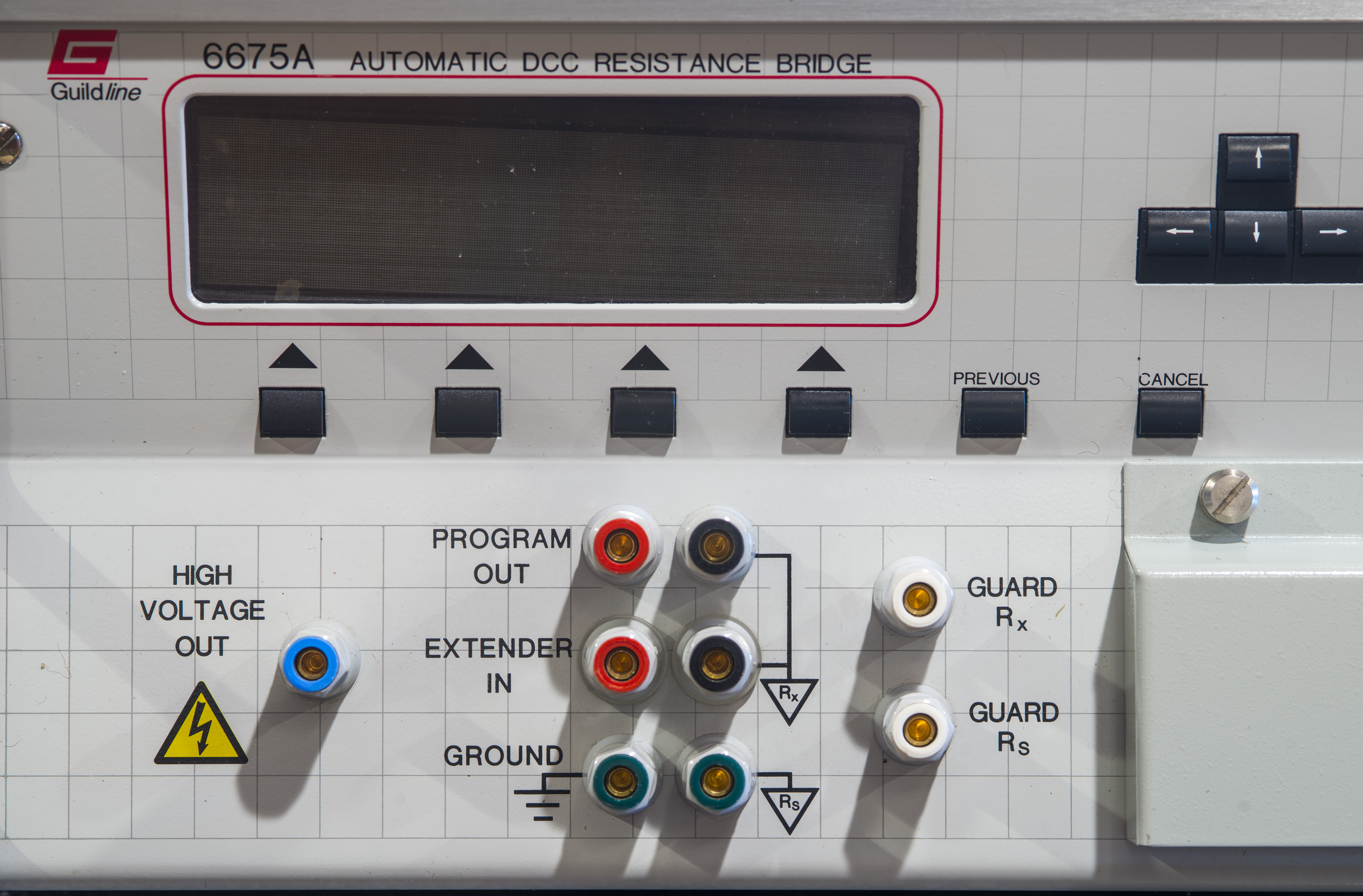
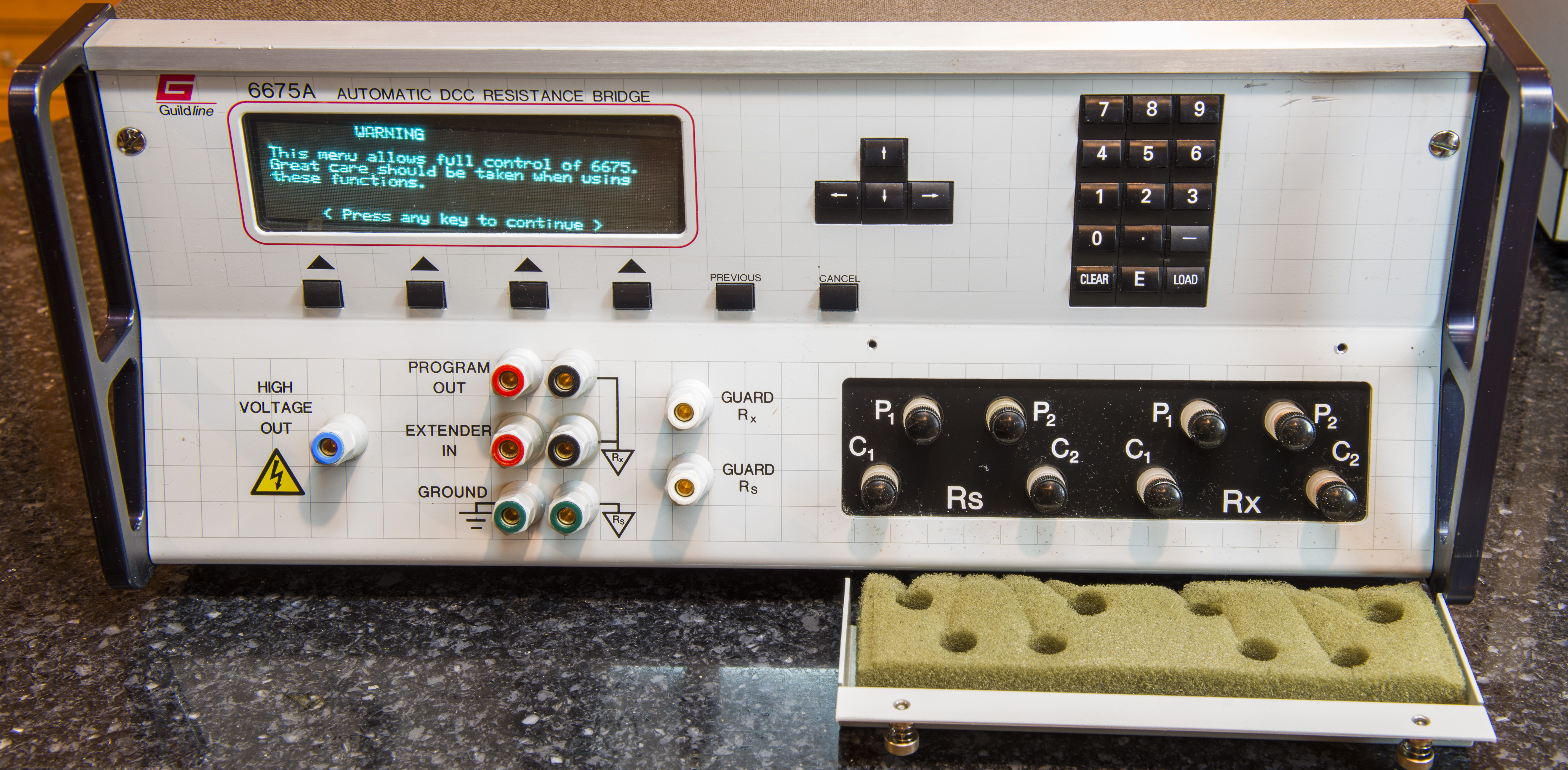
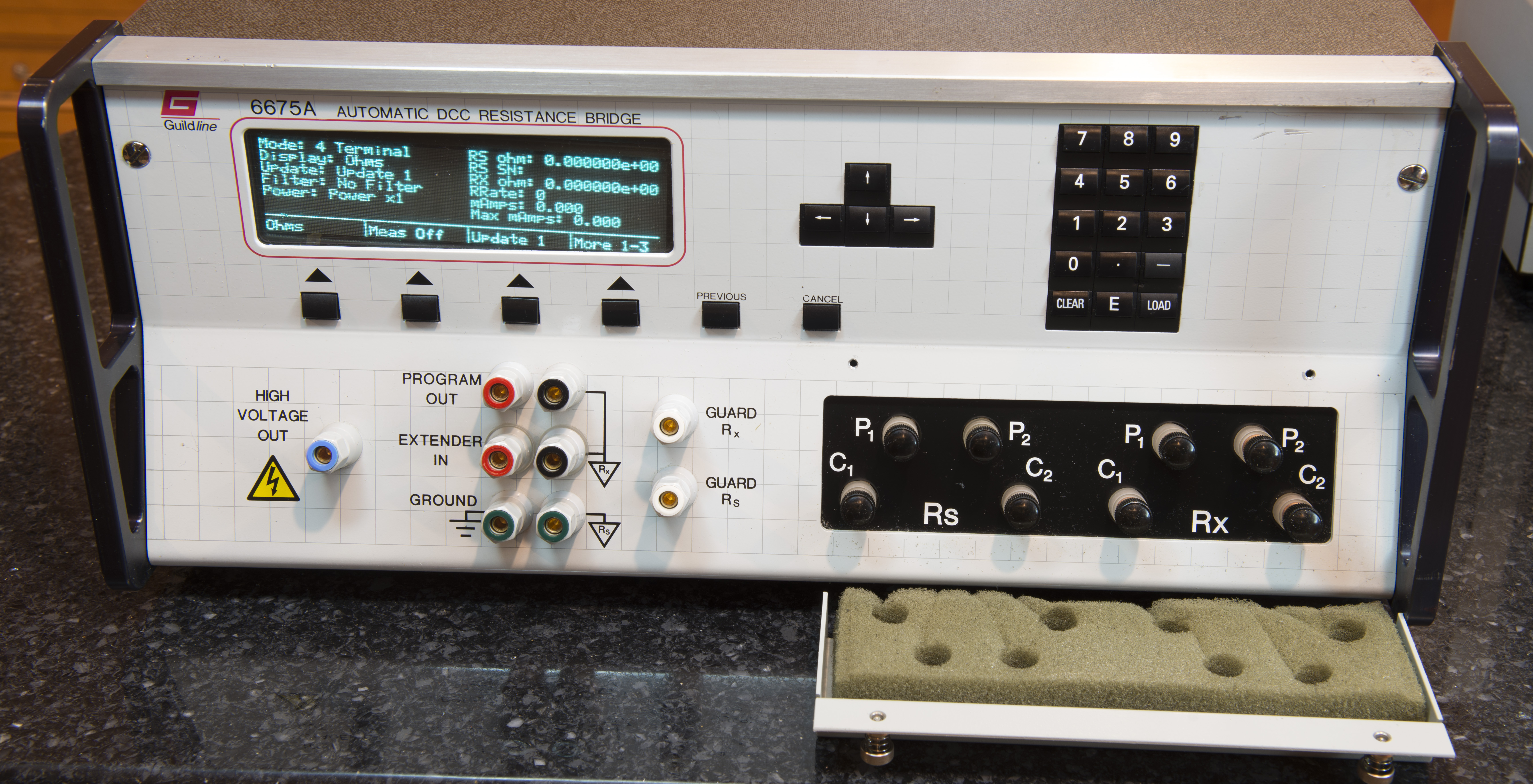
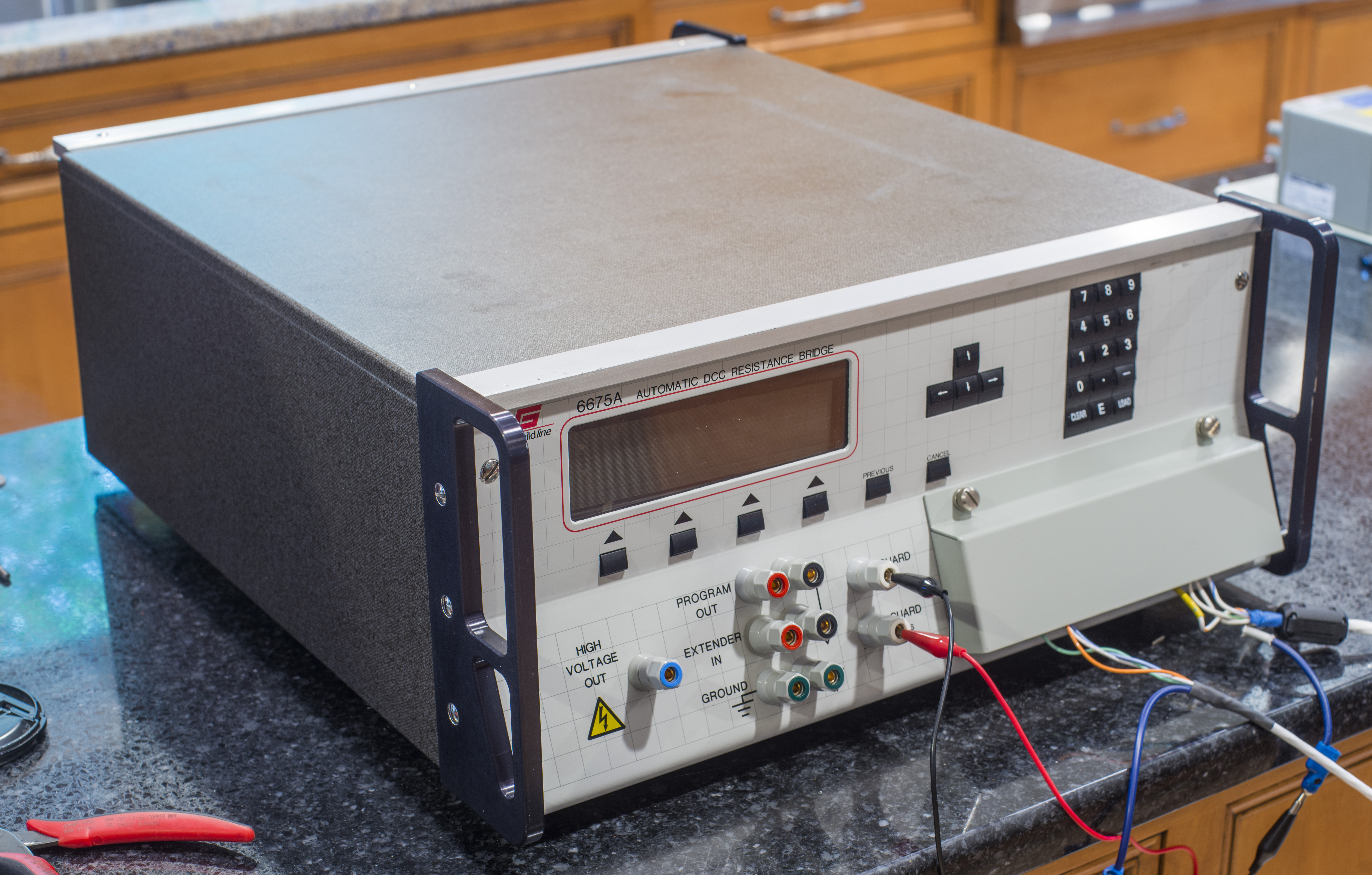
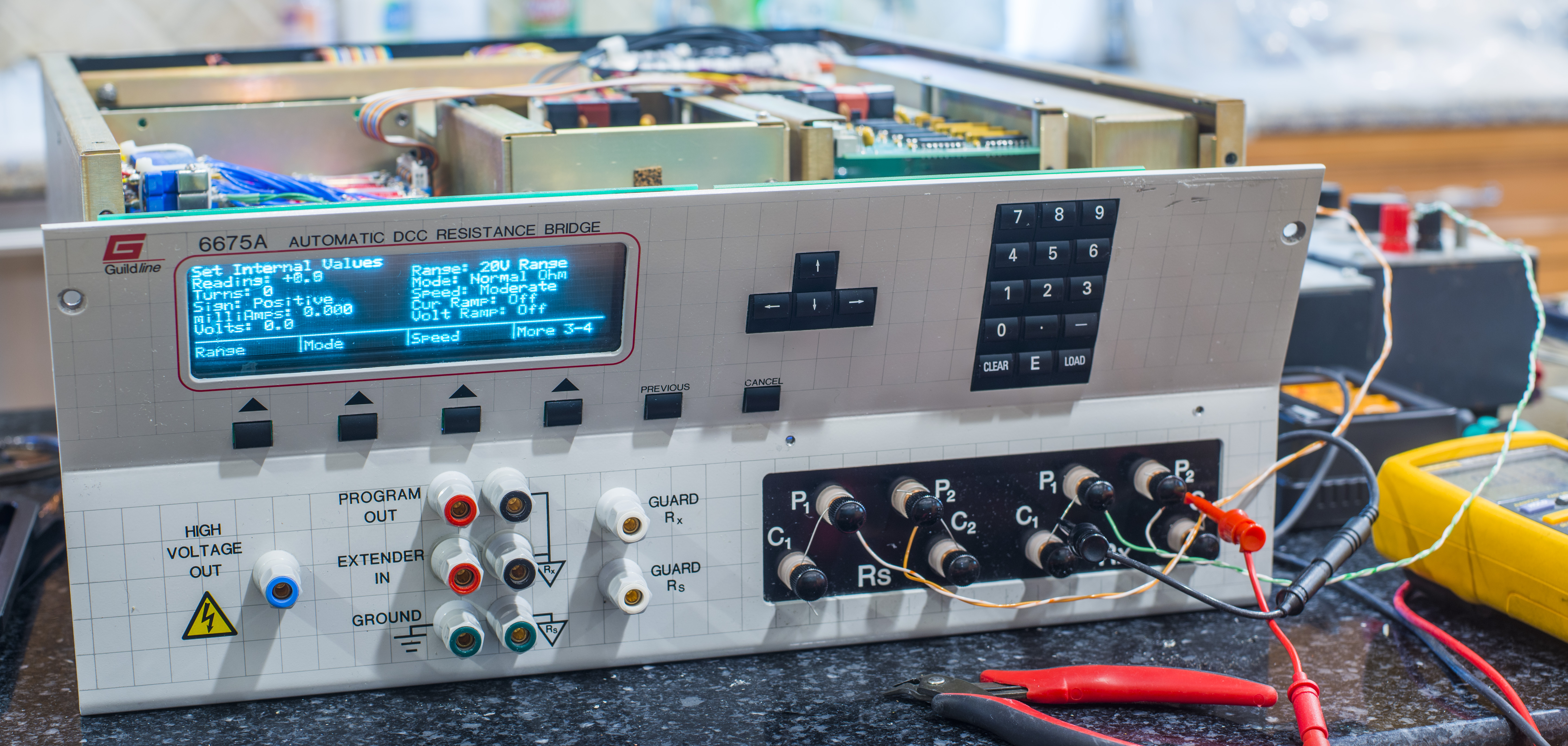
- Guildline 6675A DCC bridge
- Guildline 6623 100A high current extender for low resistance measurements
Intro
Model Guildline 6675A is an automated Direct Current Comparator (DCC) bridge designed for ultra-precision resistance and thermometer applications. It is evolution of well-recognized Guildline model 9975 that was and still is in use in many Standards Laboratories around the world. Today this model is obsoleted and replaced by the improved 10½-digit Model 6622A DCC bridge . Typical MSRP for these impressive instruments is around $50k USD or more. There is very limited competition in the world for such high precision resistance measurements, with another known player being Measurement International and their 6010 line DCC bridges.
The bridge can be used in Normal or High Ohms while maintaining automatic ampere turn balancing. Automatic current reversal is selectable from 4 seconds to greater than 1 hour. The built in stable to 1 ppm current supply permits selection of output currents between 1μA and 150 mA. Standard on the 6675A is a built in voltage source enabling selection from 16 volts to 990 volts with automatic voltage reversal for measurements above 10kΩ. It is micro-processor based and shows the ratio measurement results to an accuracy of better than 0.1 ppm. The linearity of the bridge is better than 0.01 ppm of full scale and the resolution is amazing 1 ppb, essentially providing 9½ digits for user.
Disclaimer
Redistribution and use of this article or any images or files referenced in it, in source and binary forms, with or without modification, are permitted provided that the following conditions are met:
- Redistributions of article must retain the above copyright notice, this list of conditions, link to this page (https://xdevs.com/article/g6675a/) and the following disclaimer.
- Redistributions of files in binary form must reproduce the above copyright notice, this list of conditions, link to this page (https://xdevs.com/article/g6675a/), and the following disclaimer in the documentation and/or other materials provided with the distribution, for example Readme file.
All information posted here is hosted just for education purposes and provided AS IS. In no event shall the author, xDevs.com site, or Guildline or any other 3rd party be liable for any special, direct, indirect, or consequential damages or any damages whatsoever resulting from loss of use, data or profits, whether in an action of contract, negligence or other tortuous action, arising out of or in connection with the use or performance of information published here.
If you willing to contribute or have interesting documentation to share regarding pressure measurements or metrology and electronics in general, you can do so by following these simple instructions.
Manuals
Model 6675A Automatic DCC Resistance/Temperature Bridge datasheet
TECHNICAL MANUAL FOR MODEL 6675A AUTOMATIC DCC BRIDGE, VOL I, TM6675A-C-00, January 30, 2001
ADDENDUM, Issue September 24, 2007
ADDENDUM, Issue April 29, 2008
TECHNICAL MANUAL FOR ResCal™ 3.4 MODEL 6675/A, VOL II, TM6675A-D-00, October 25, 2002
Reverse-engineered primary PCB schematics, by pipelie
Guildline 6675 Direct Current Comparator bridge

First tests and operational checks

First transfer experiments
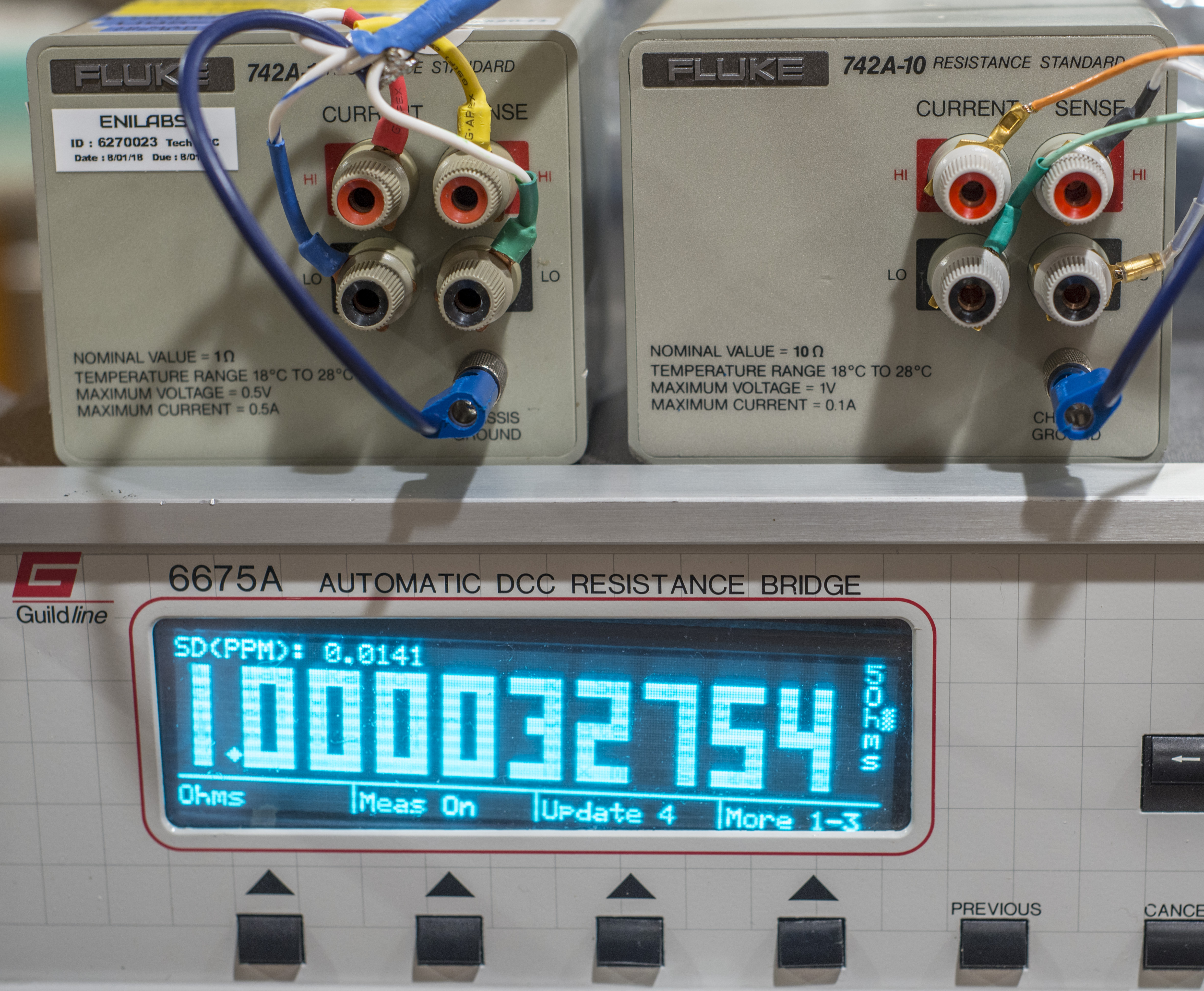
Photo above shows ratio measured between calibrated Fluke 742A-1 resistance standard (1.00004374 Ω on October 27, 2020 with uncertainty ±0.46 ppm by IET Labs) to Fluke 742A-10 standard that we repaired some time ago.
10 Ω resistance was calibrated back then using Fluke 5720A as +10/-10/+10 mA current source and Keysight 34420A nanovoltmeter
Obtained value then was equal to 10.000121 Ω.
By using measured ratio from Guildline 6675A DCC and known resistance standard 1.00004374 Ω we can calculate 10 Ω standard as below:
1.00004374 Ω / (1.000032754 × x10 (ratio) ) = 10.0001098 Ω ±0.15 ppm of transfer
This agrees quite well with previous result obtained with 5720A/34420A : ((10.0001098 / 10.000121) – 1) * 106 = -1.120 ppm.

Used settings were 30 second reversal ratio time, 20 mA current and Update 4 mode.
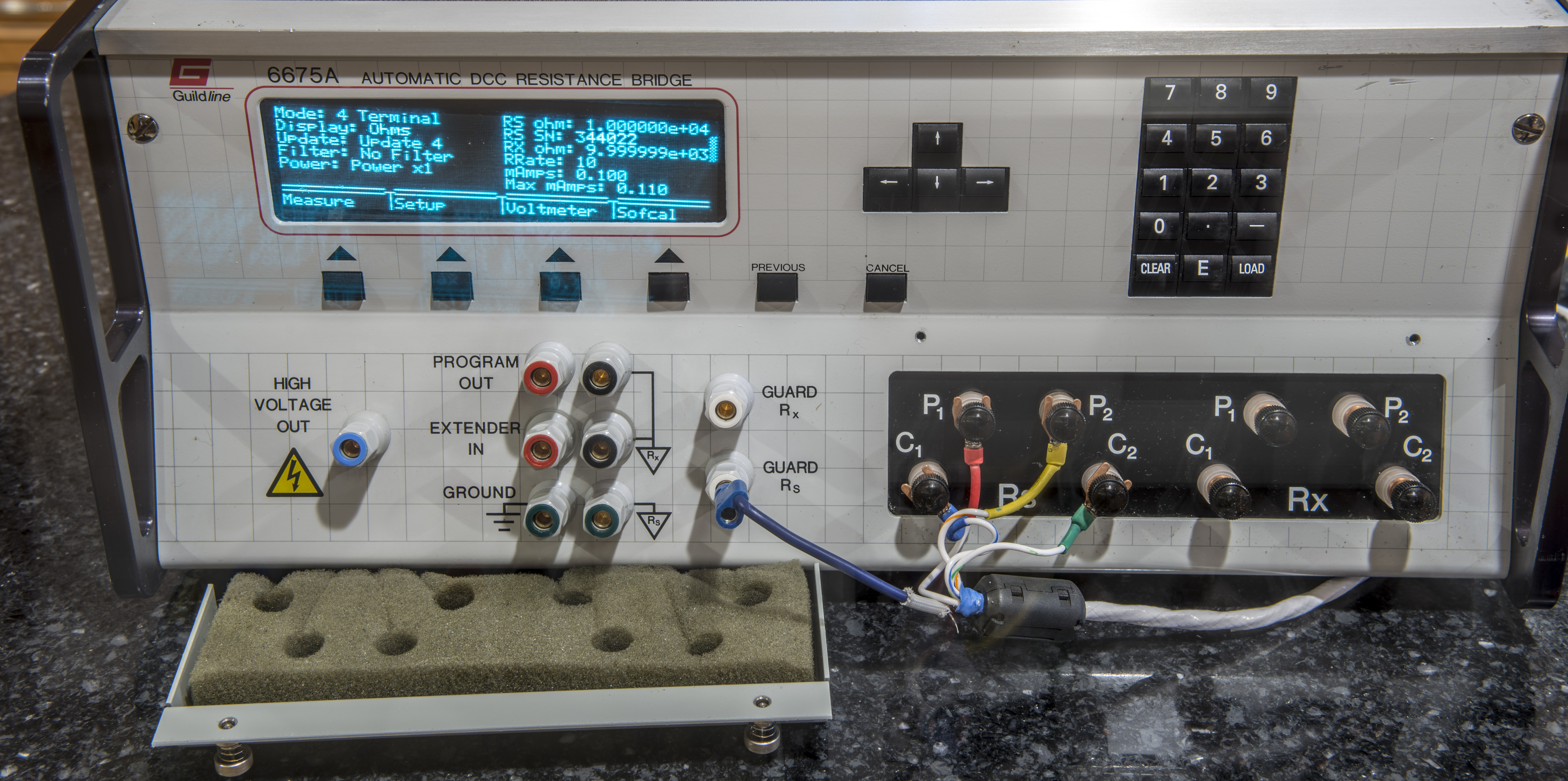
Second experiment was done measuring ratio between two ESI SR104 10000 Ω resistance standards. These two standards were calibrated August 8, 2021 using characterized Datron 1281 and calibrated tandem of ESI SR104, known to ±0.1 ppm.
Obtained value for standard N1 = 9999.9988 Ω and for N2 = 10000.0332 Ω
By using measured ratio from Guildline 6675A DCC and reference resistance 9999.9988 Ω we can calculate second SR104 standard as below. Standard deviation of multiple ratio readings was pretty impressive 0.029 ppm:
9999.9988 Ω / (0.9999964952 × x1 (ratio) ) = 10000.03385 Ω ±0.15 ppm of transfer
This agrees quite well with previous result obtained with Datron 1281 : ((10000.03385 / 10000.0332) – 1) * 106 = +0.0648 ppm.
Settings used were 100 µA current and reversal ratio 25.
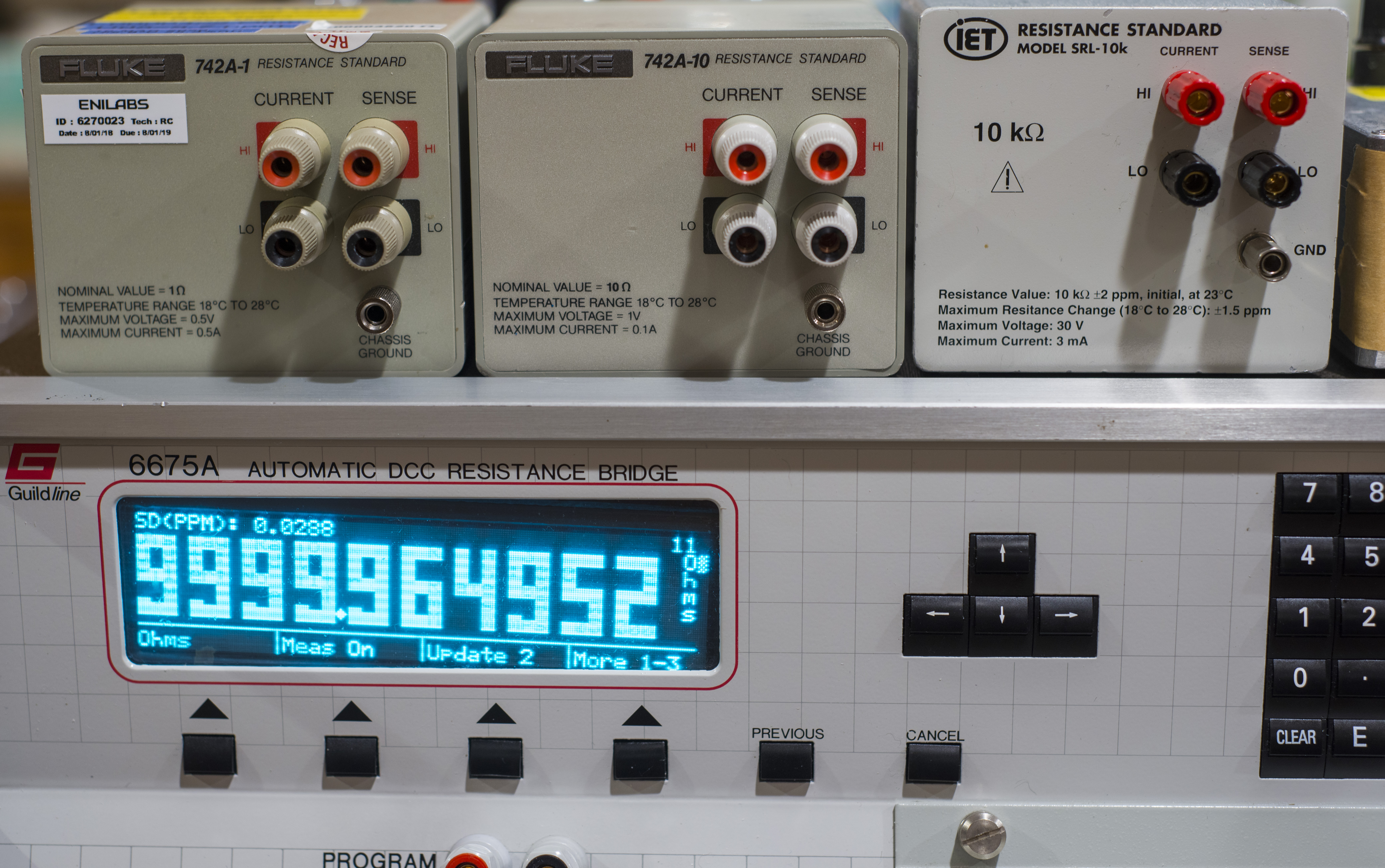
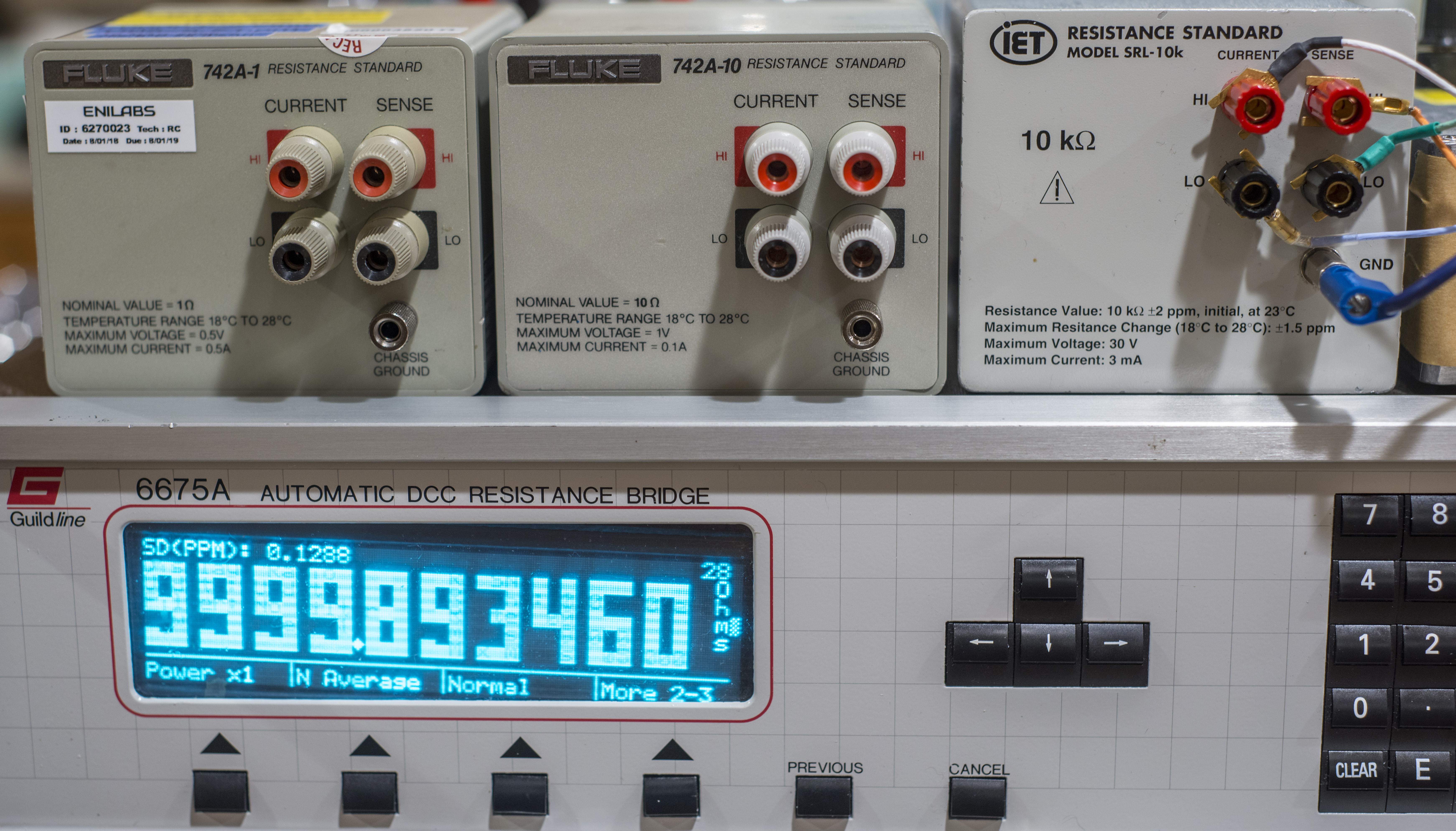
Third experiment was done measuring ratio between same 9999.9988 Ω ESI SR104 10000 Ω resistance standard and IET SRL-10kΩ. IET SRL was calibrated by transfer from reference xDevs.com’s ESI SR104 with help of Keysight 3458A. This transfer established SRL-10k value at 10000.095 Ω and was completed on 30 December 2020.
By using measured ratio from Guildline 6675A DCC and reference resistance 9999.9988 Ω we can calculate current IET SRL-10k standard as below. Standard deviation of multiple ratio readings was 0.129 ppm:
9999.9988 Ω / (0.9999893460 × x1 (ratio) ) = 10000.10534 Ω ±0.15 ppm of transfer
This agrees with previous result obtained with Keysight 3458A within ((10000.10534 / 10000.095) – 1) * 106 = +1.034 ppm.
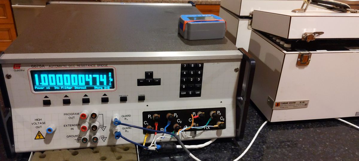
Another dual ESI SR104 ratio test between 10000 Ω resistance standards. Reference standard were calibrated June 8, 2021 at Measurement International lab using their transfer methods and MI 6010D bridge, resulting 10000.0013 Ω with very low uncertainty ±0.1 ppm.
10000.0013 Ω / (1.000000474 × x1 (ratio) ) = 9999.99656 Ω ±0.15 ppm of transfer
This agrees quite well with previous result obtained with Datron 1281 : ((9999.99656 / 9999.9988) – 1) * 106 = -0.224 ppm.
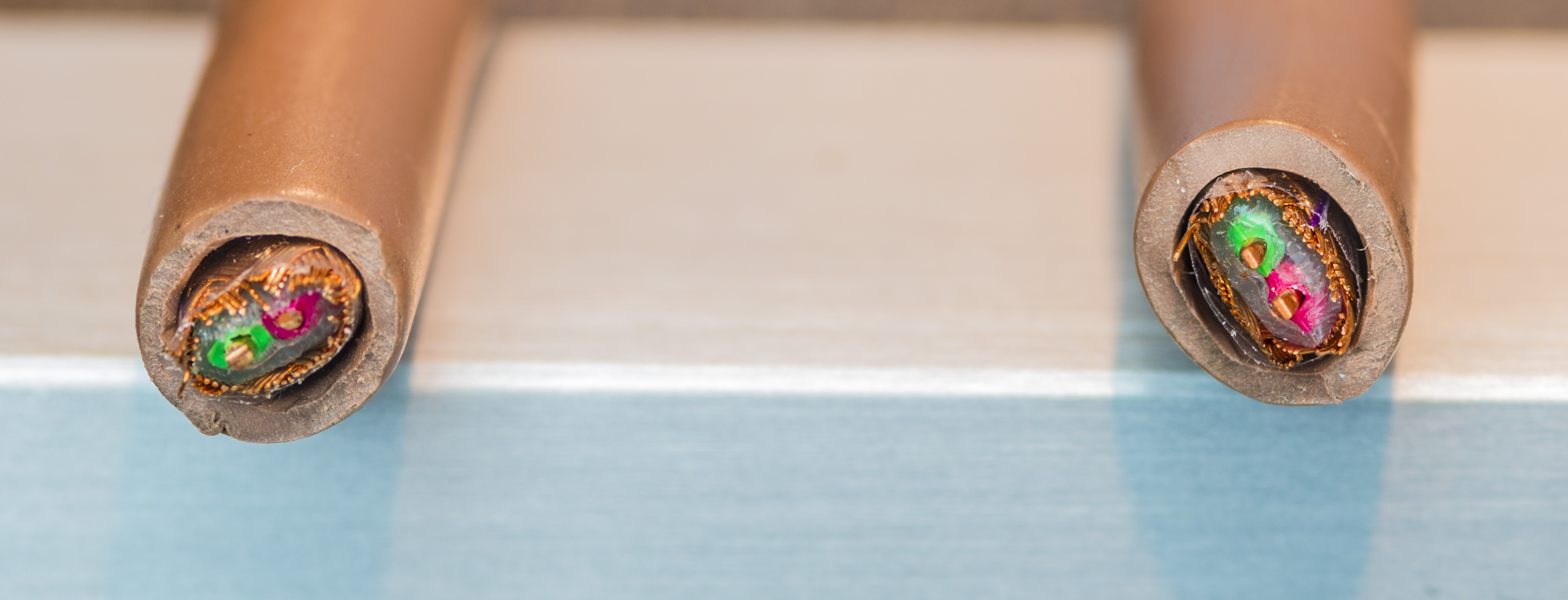
Guildline also used solid single-core copper wire with copper shielding internally in their DCC bridges. Here’s example of cable cut out of older model 9975A bridge for reference:
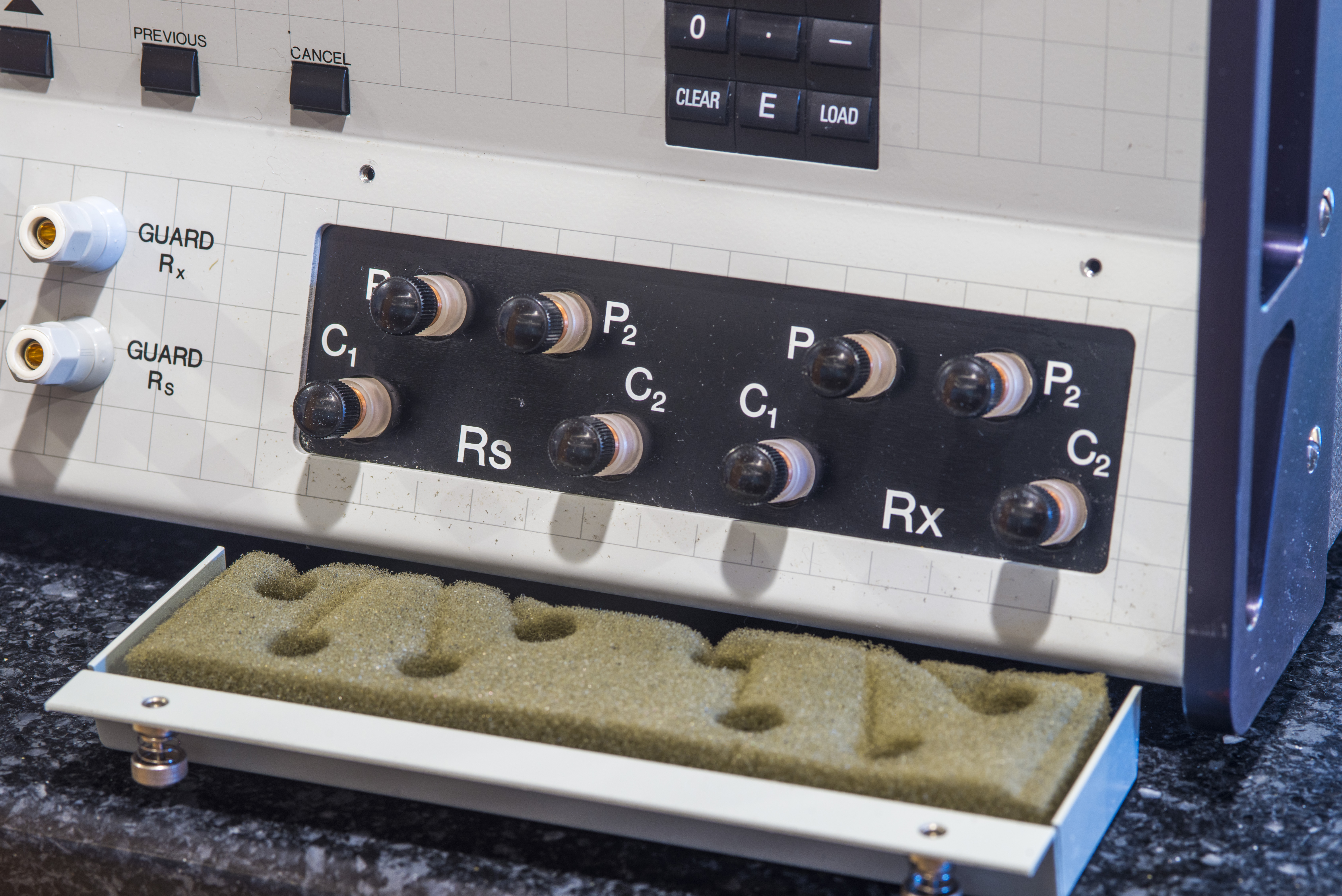
Teardown and repair
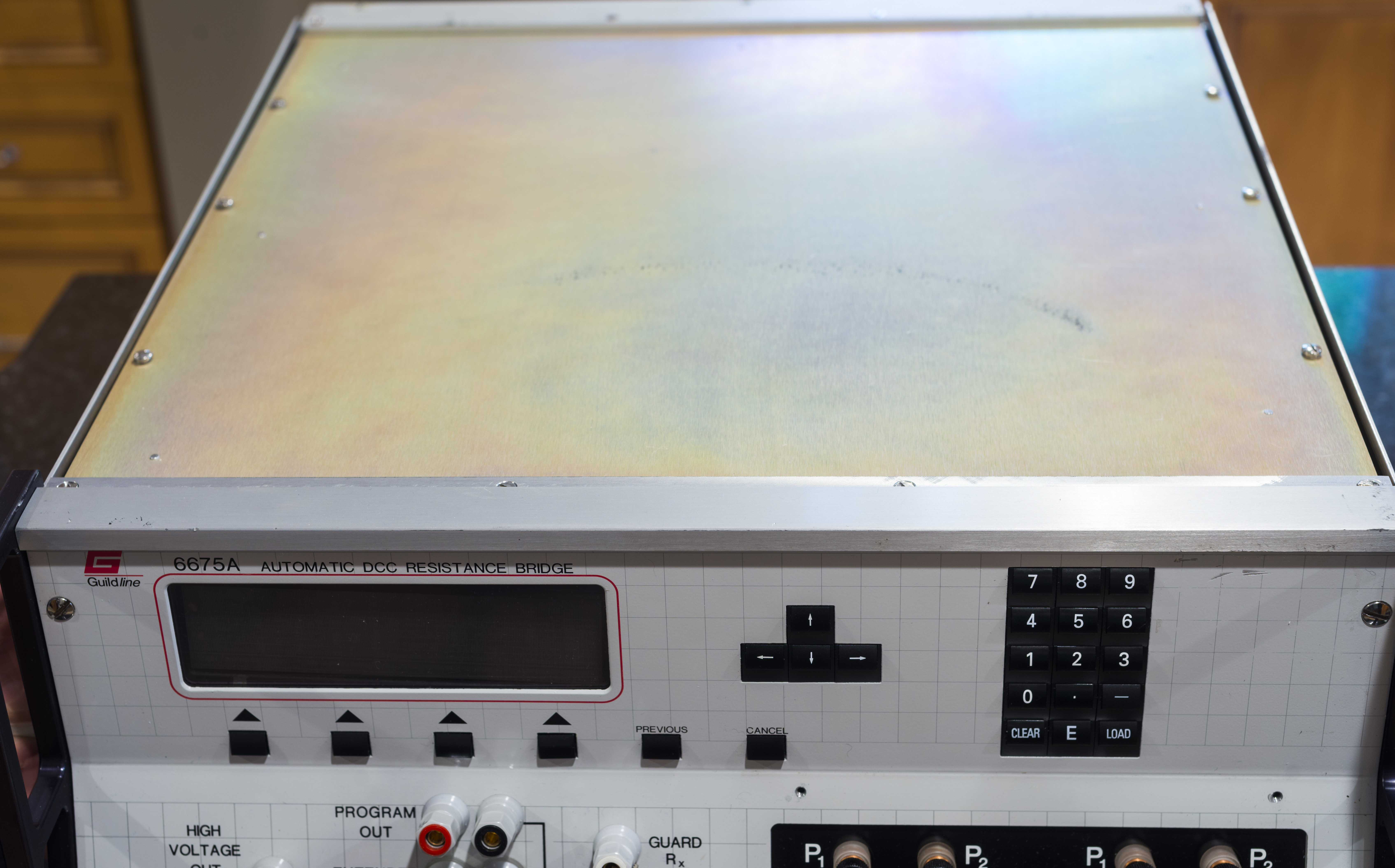
This unit came not without the issue. And it’s obvious one, front panel VFD screen is very croocked, suggesting mechanical issues with mount. We will need to remove front panel to correct for that. Condition before:
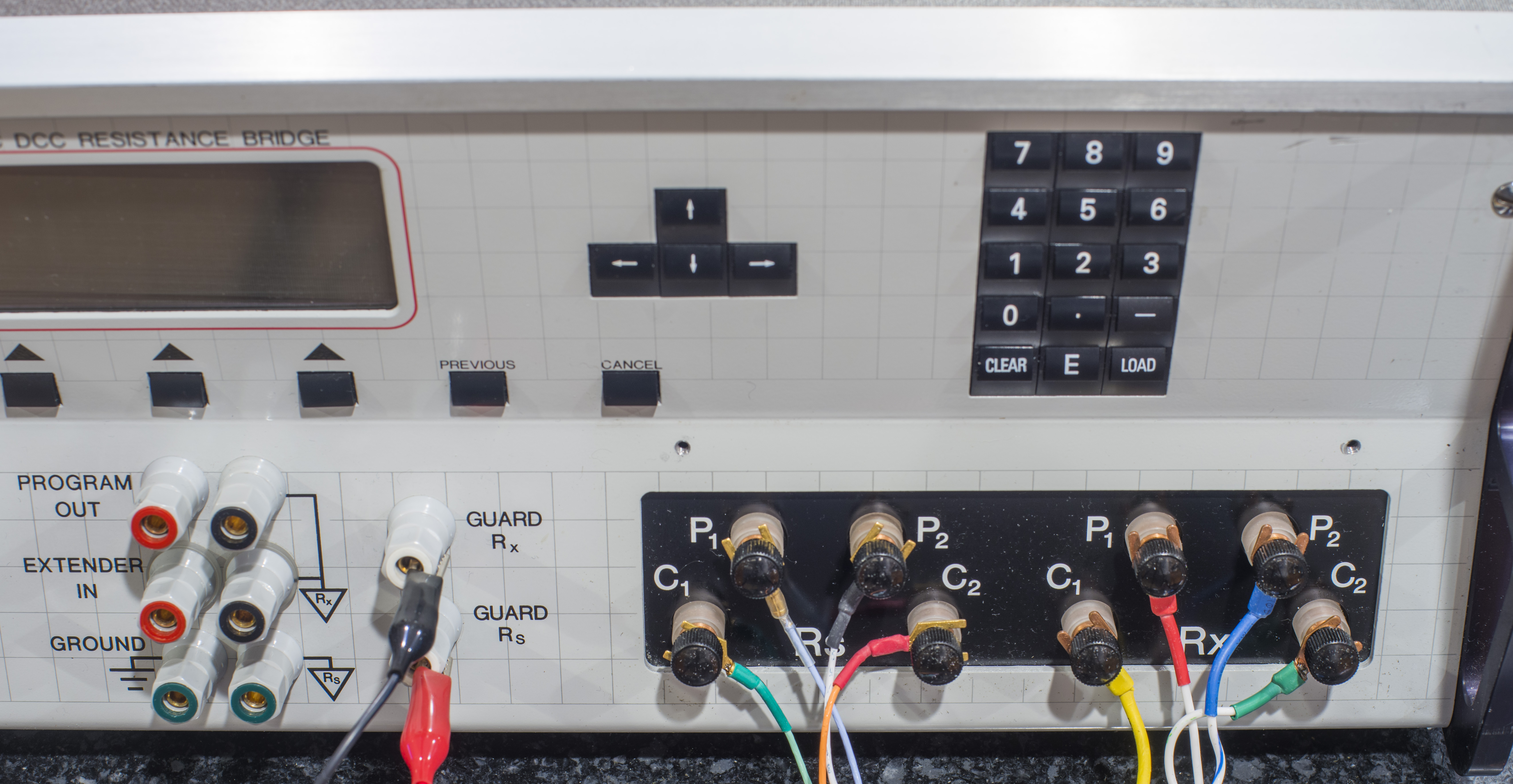
Wiring for test PTFE-insulated cables also shown for reference.
Disassembly is fairly easy with all flat-head screws. They were locked in place by blue loctite epoxy and tighten really well, be sure to you properly sized screwdriver.
There is inner shielding with µ-metal sheet lining to provide additional magnetic shielding.

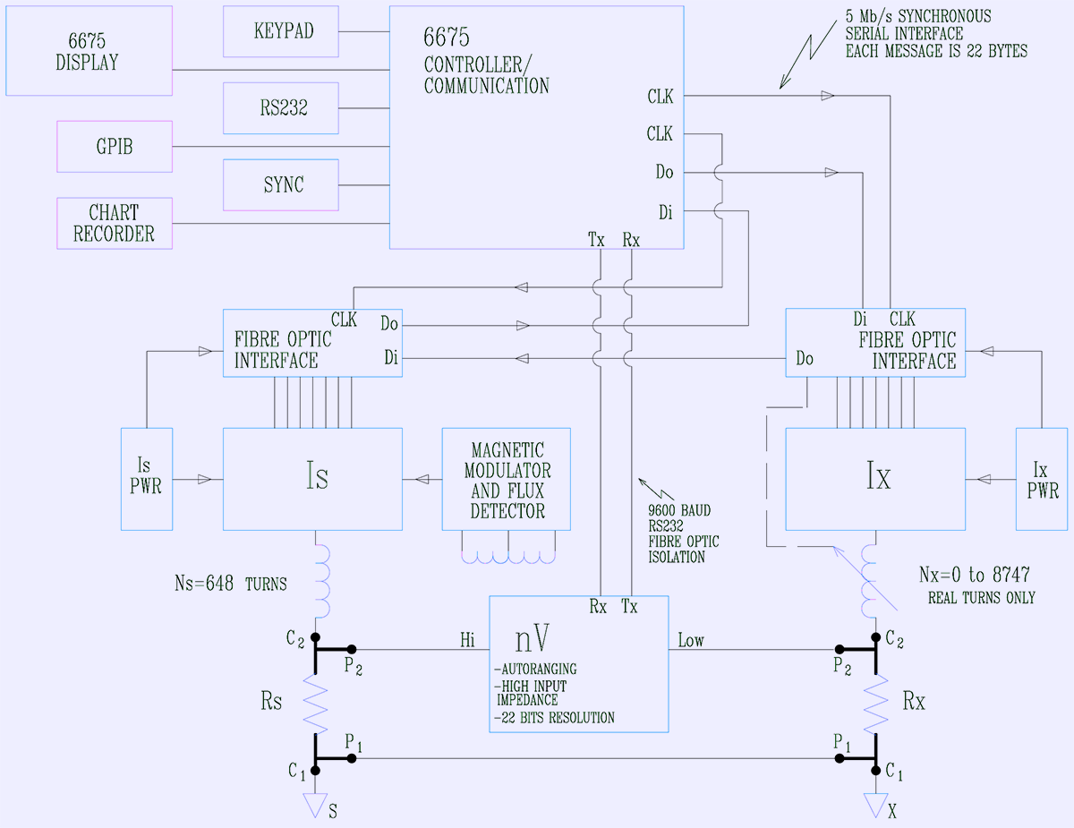
Take a moment to review Guildline 6675A block diagram from user manual.
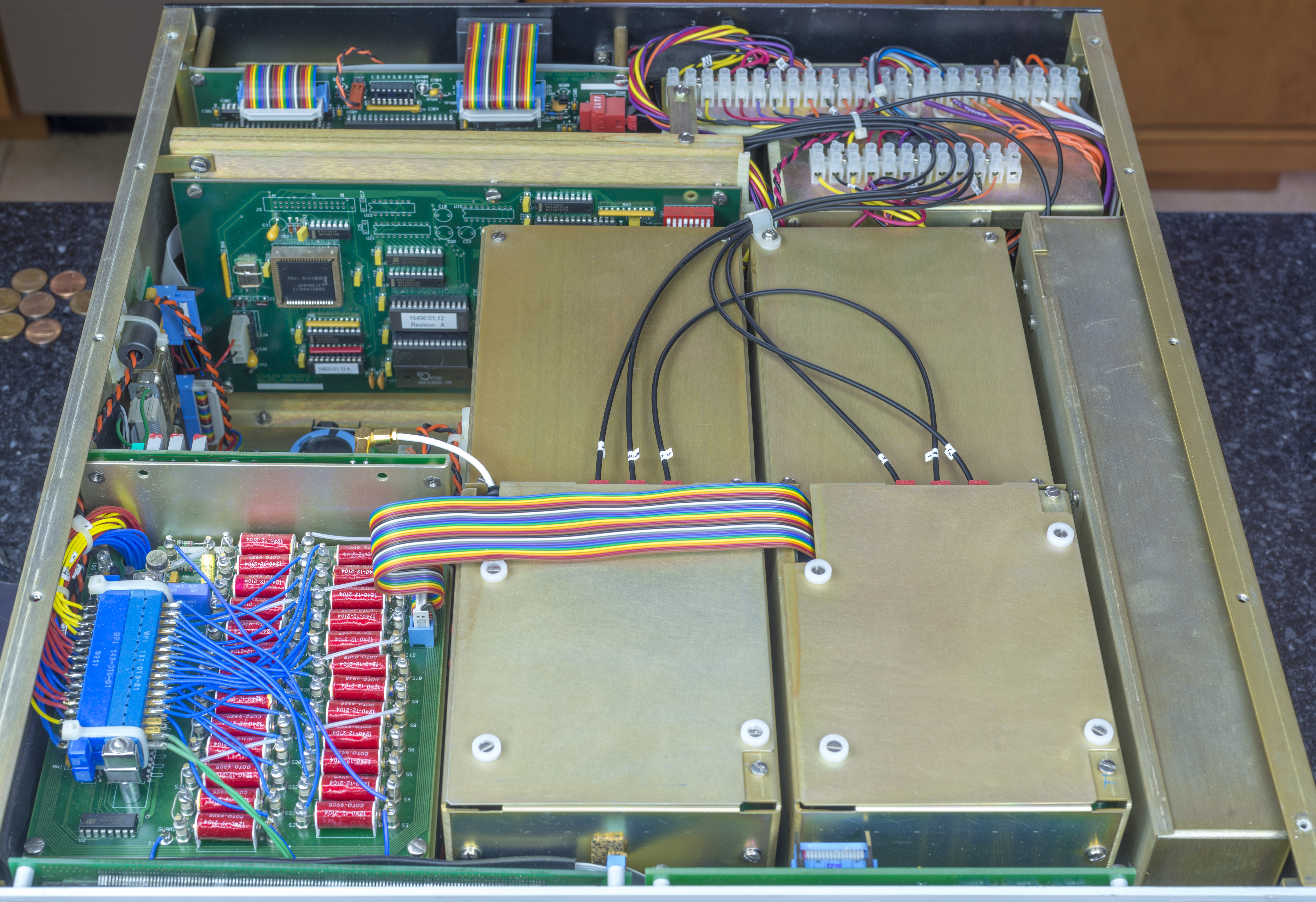
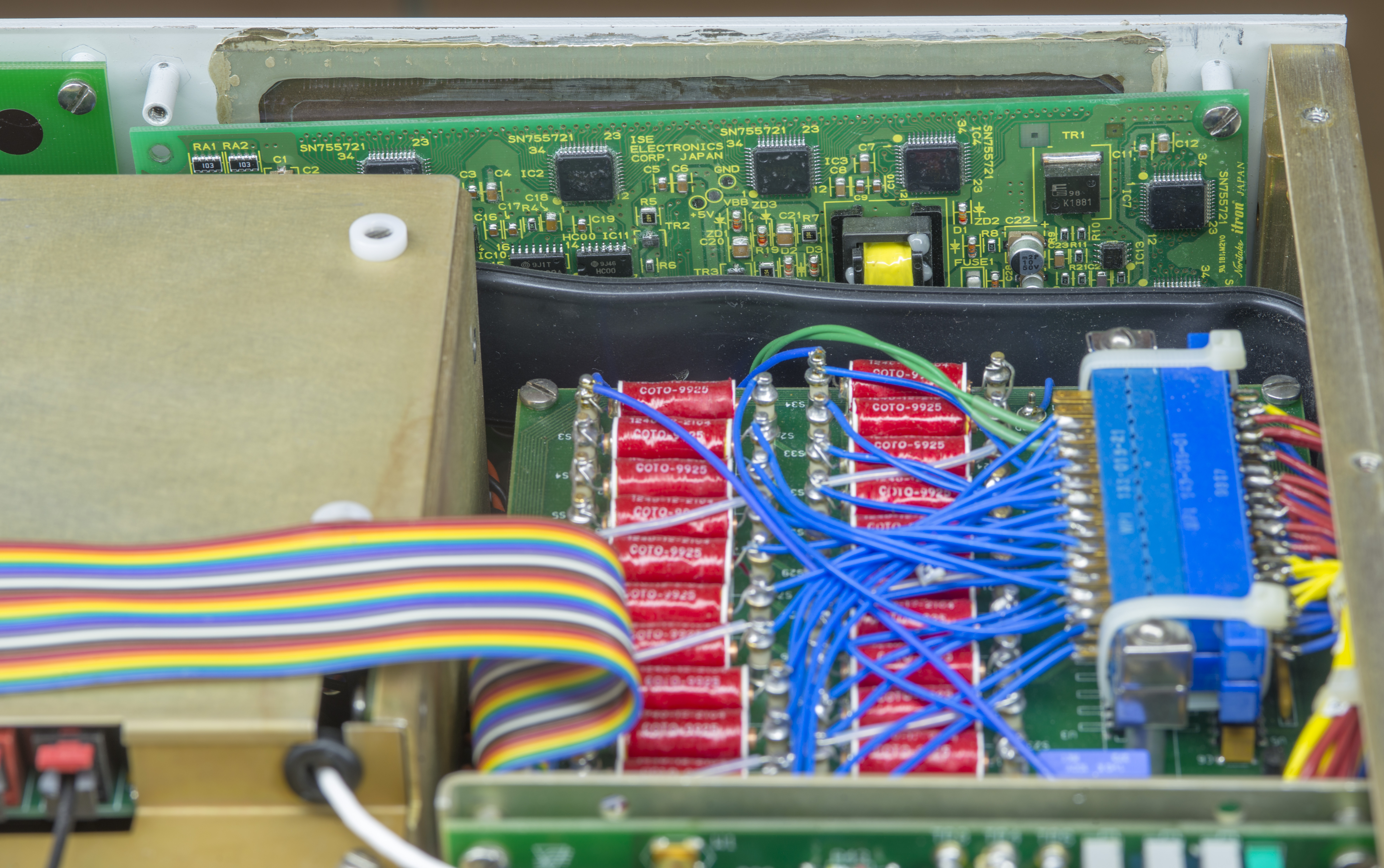
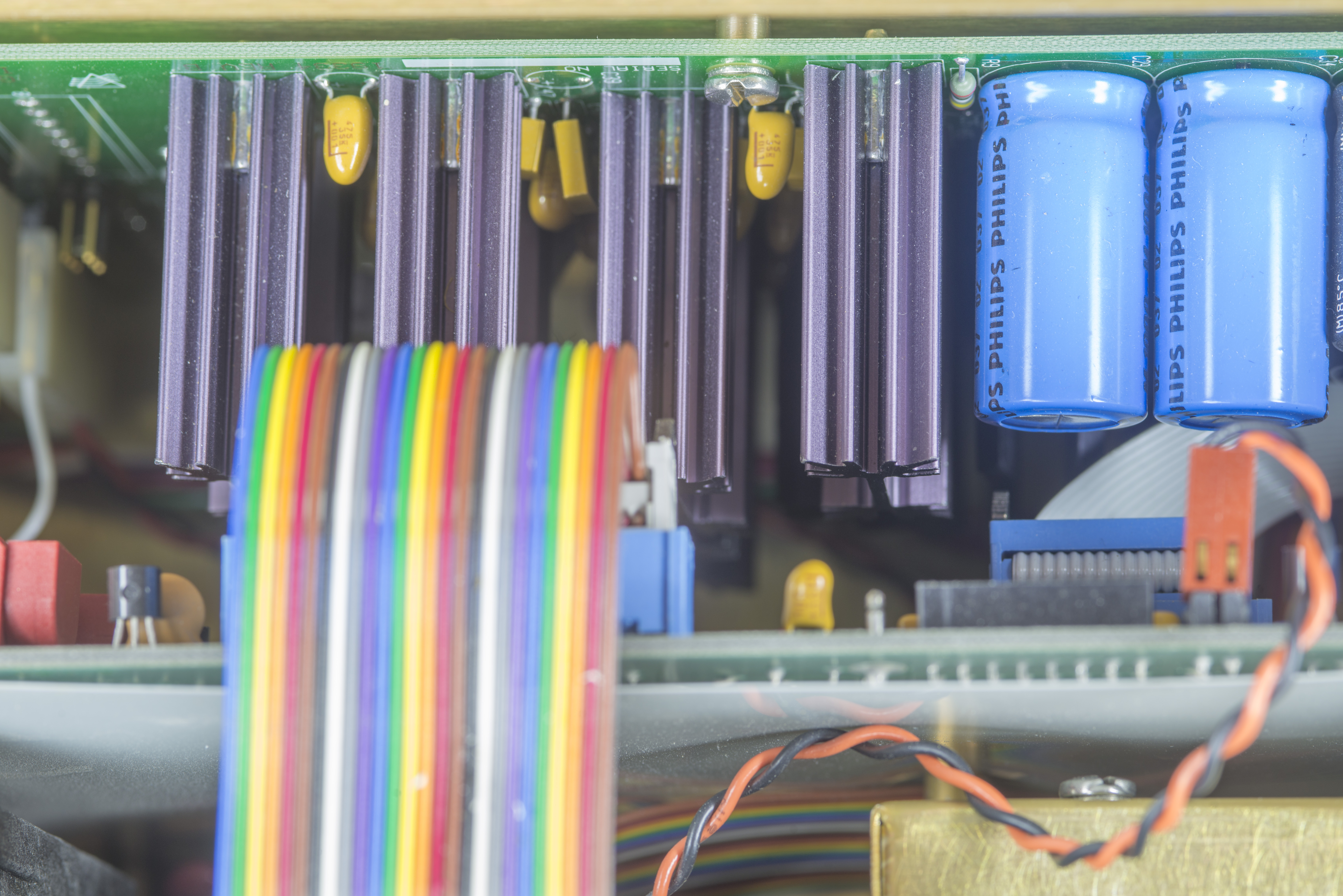
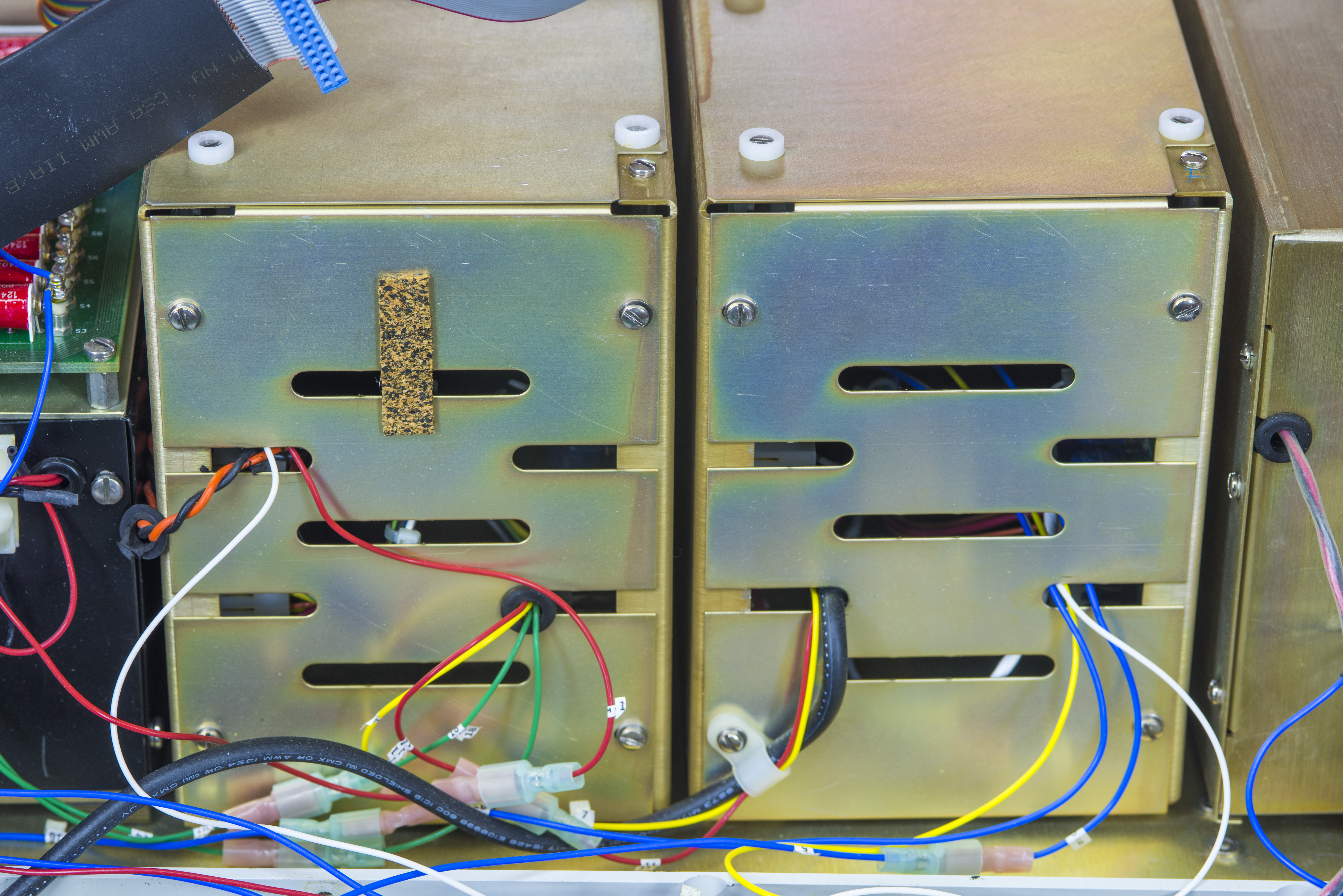
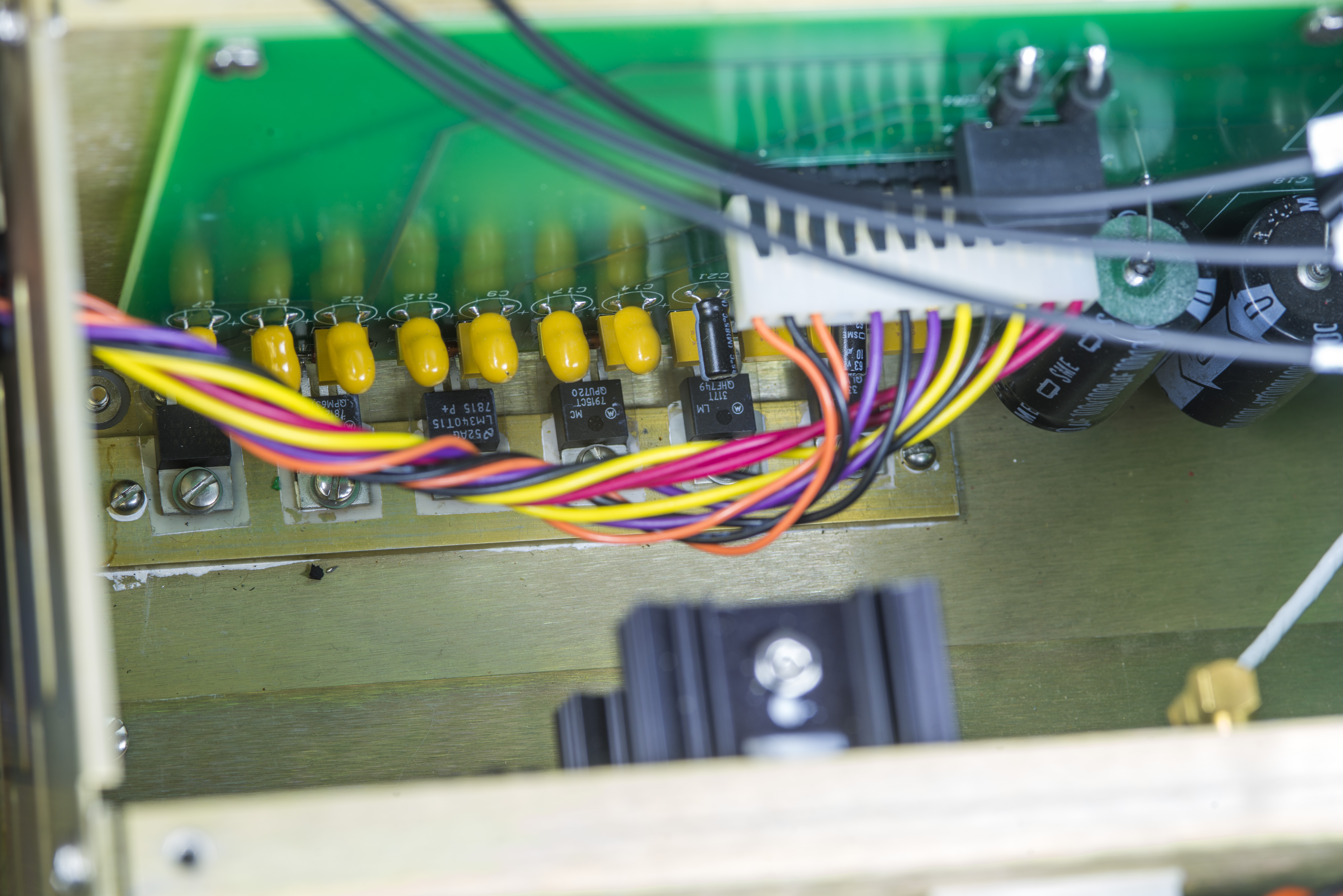
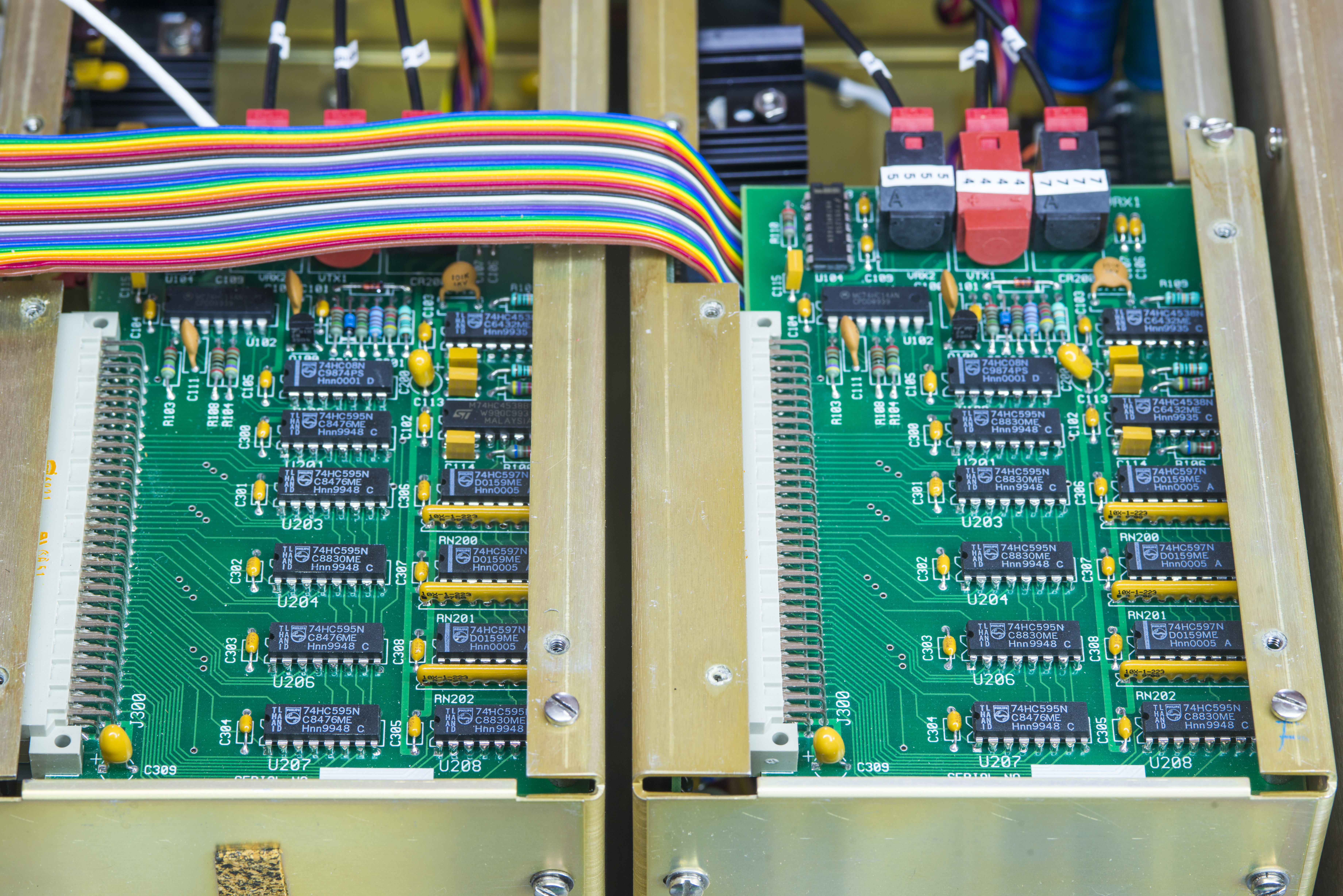
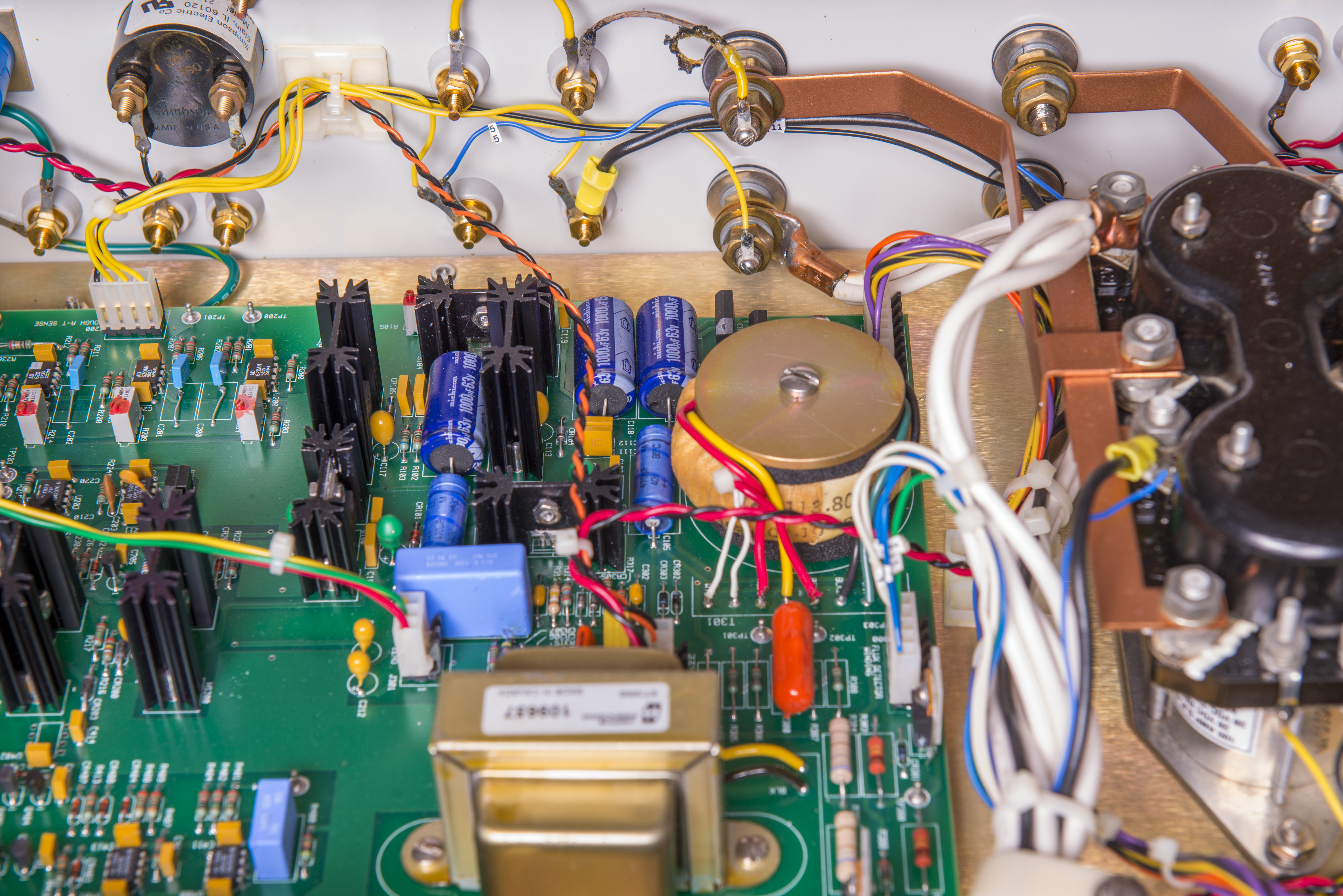
Internals are rather packed but everything is nice and tidy here. Two large enclosure boxes are isolated current sources IX and IS with their related isolated power regulator boards. Sensitive nanovolt detector is located in its own shallow enclosure mounted to the side wall of the unit. Magical DCC transformer is mounted in own insulated box under reed relay PCBA.
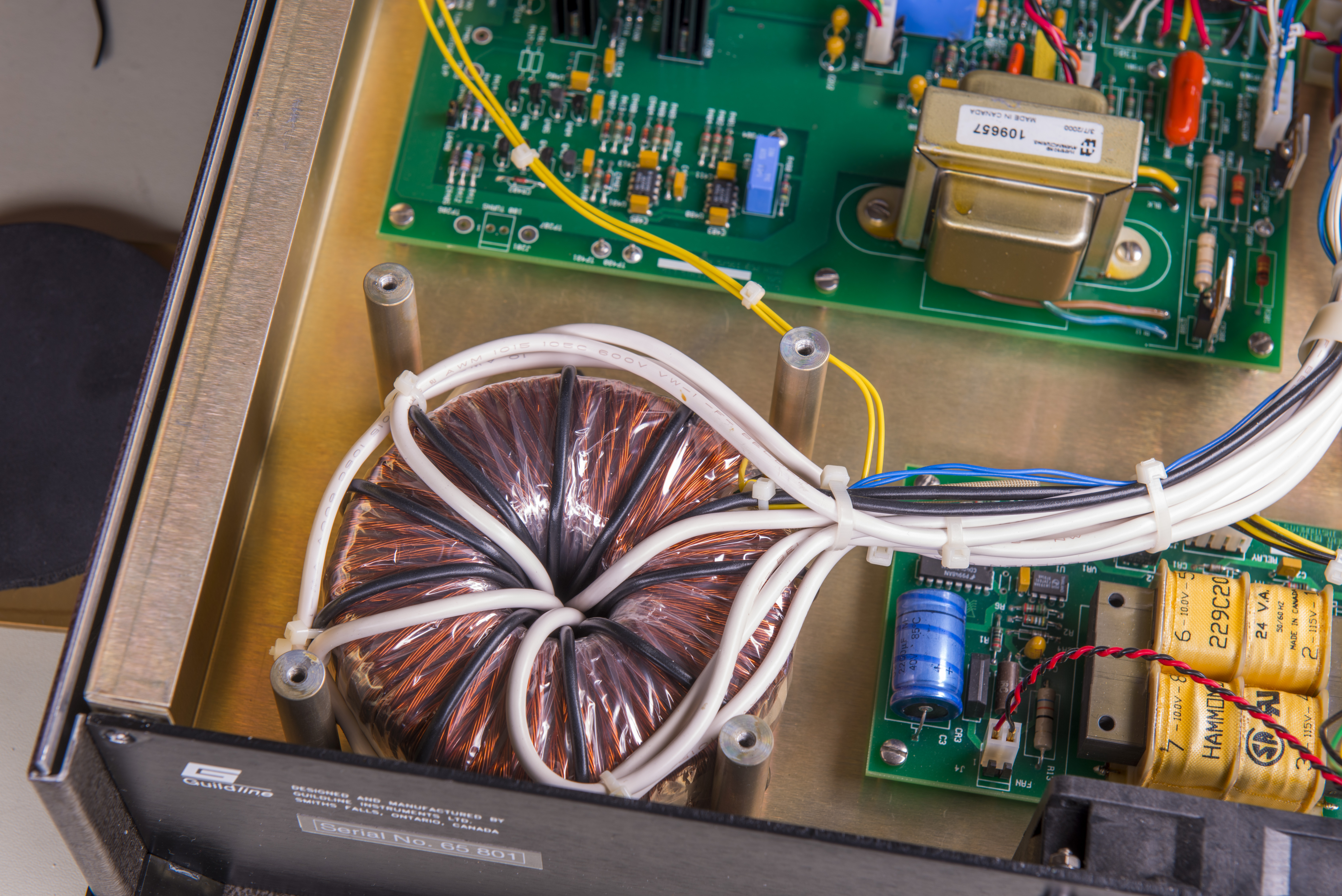
All power supplies and at least three mains transformers are all packed at the back of the instrument, together with digital processor board.
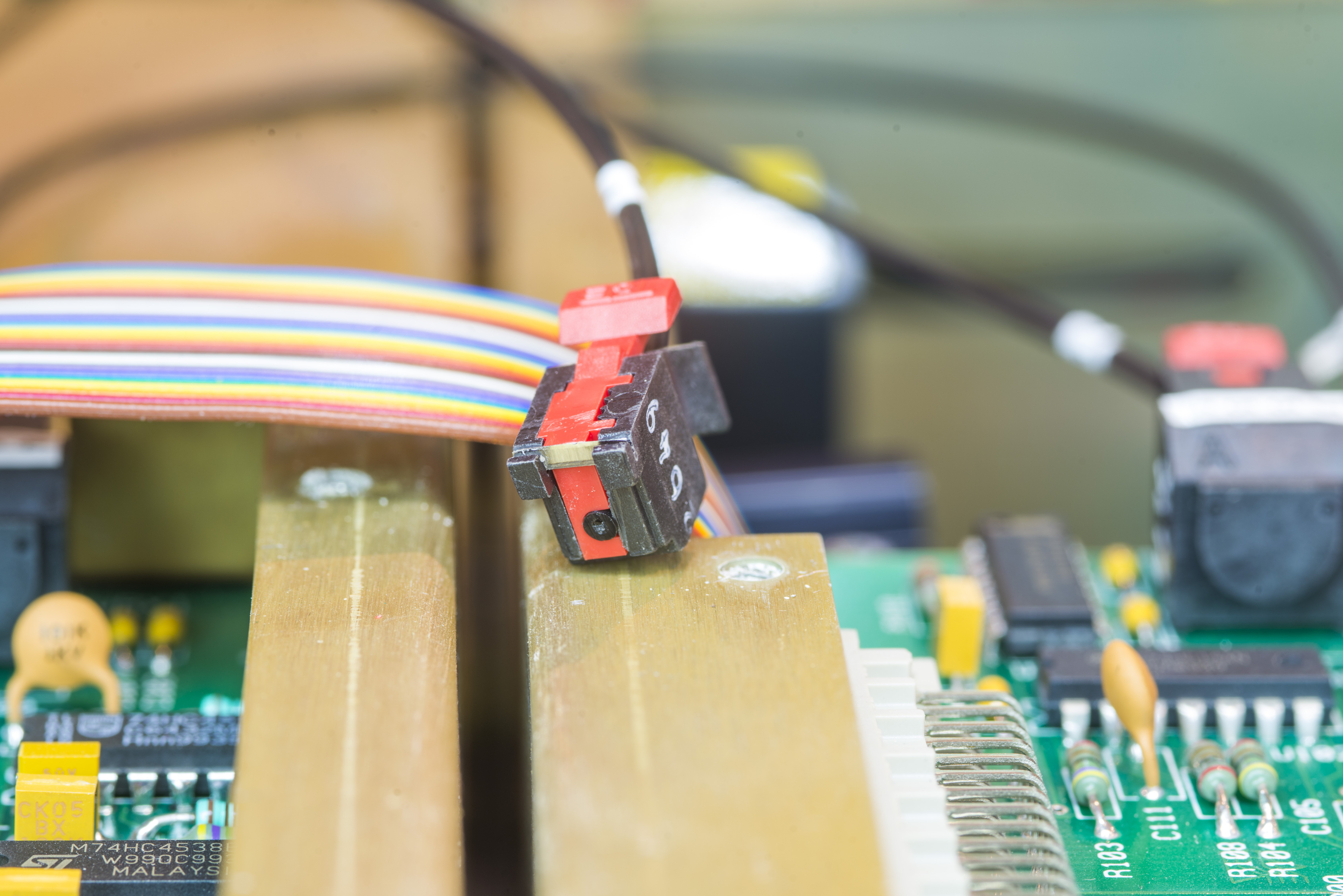
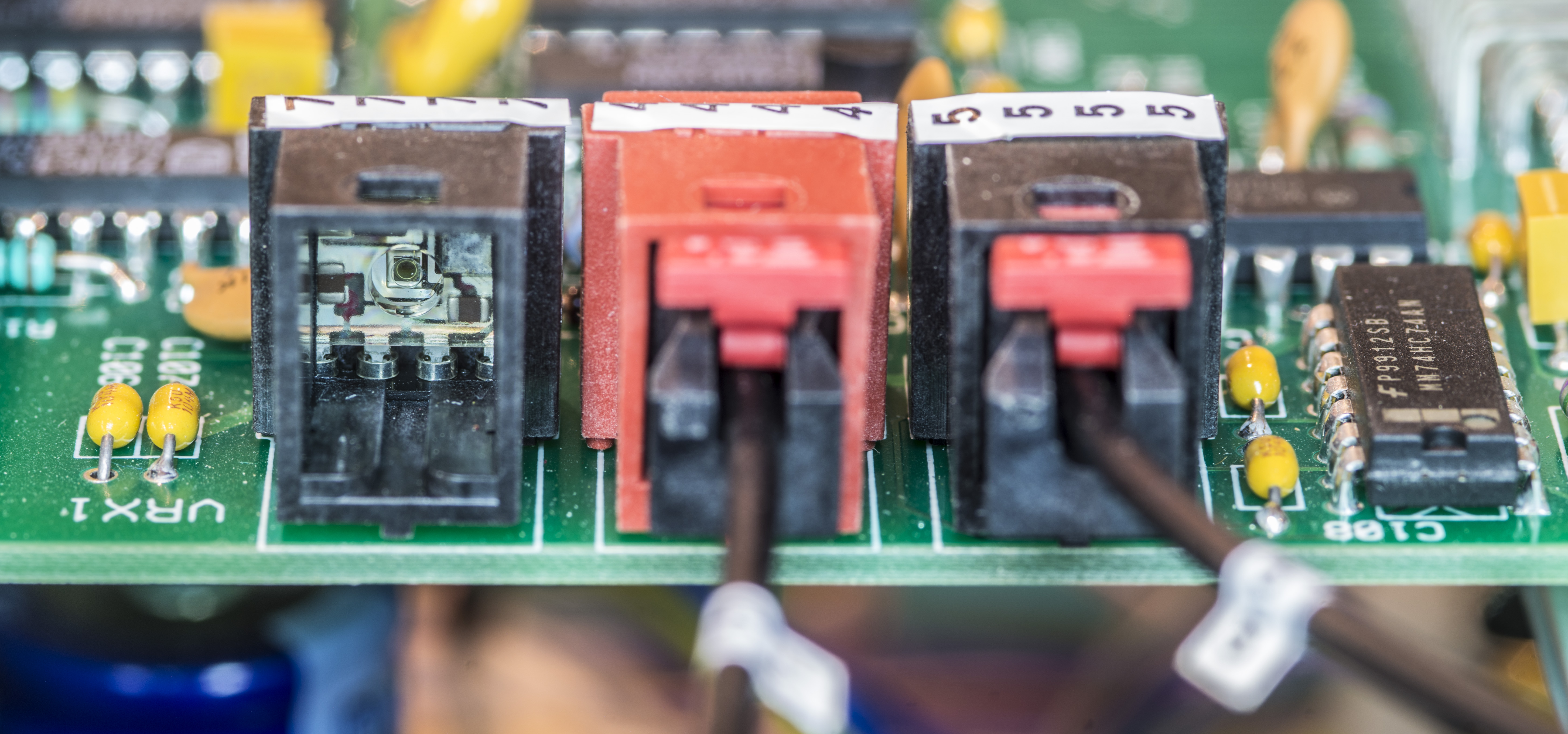
Fiberoptic cables are typical POF type, similar to what is used by HP 3458A DMM and Fluke 57** series instruments. I’m not familiar with these optical transmitter/receiver pairs however, perhaps someone can shed some light on type/brand?
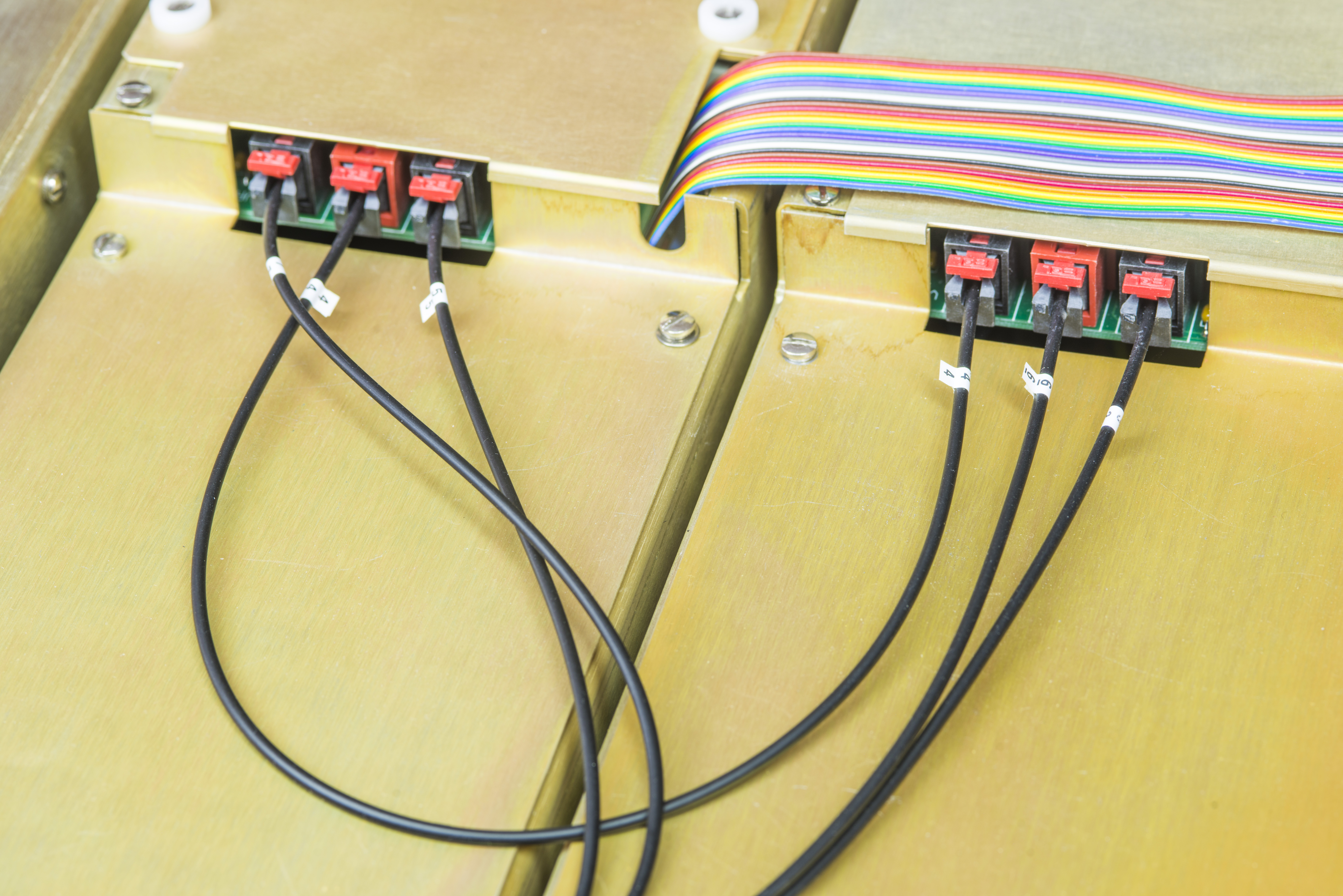
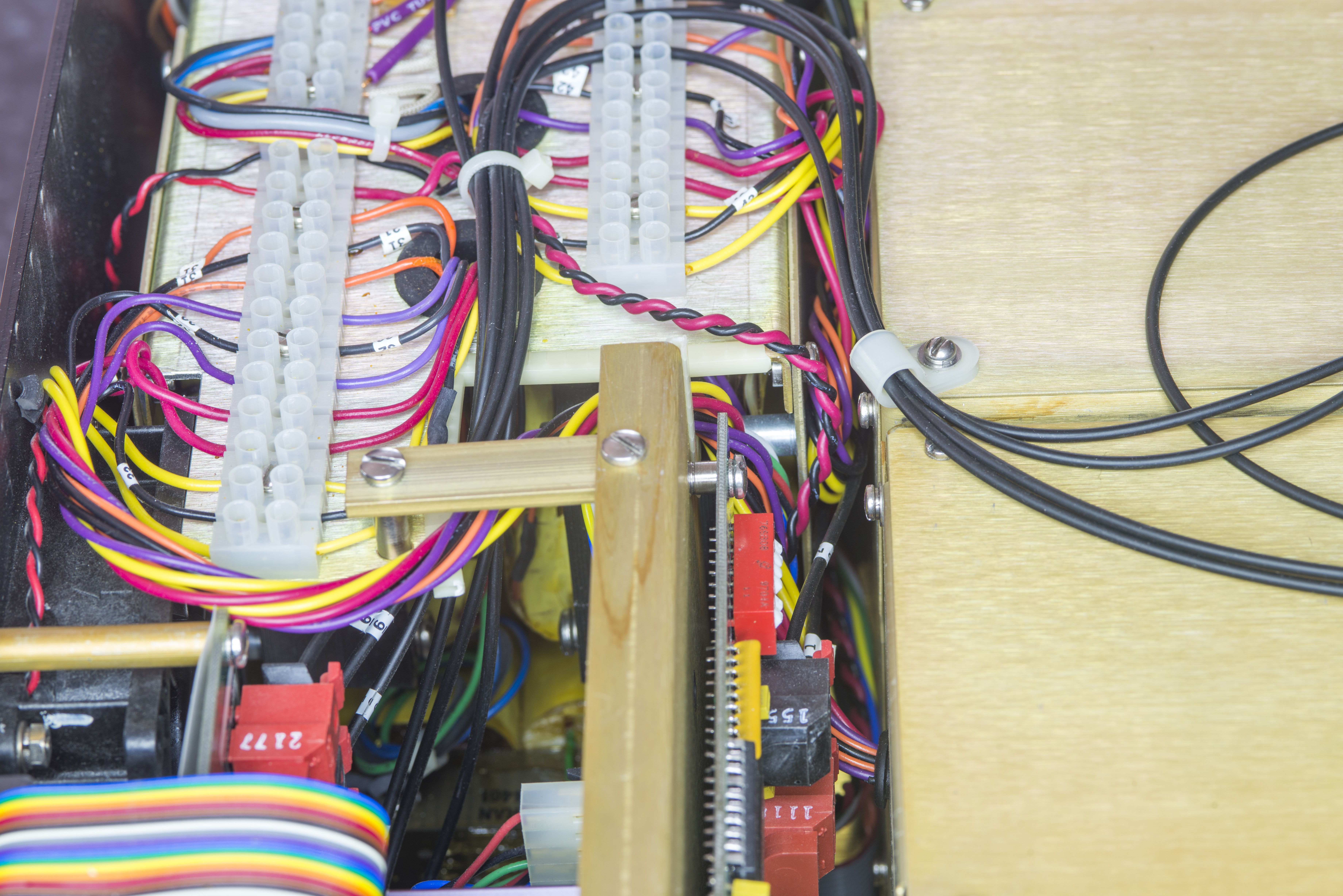
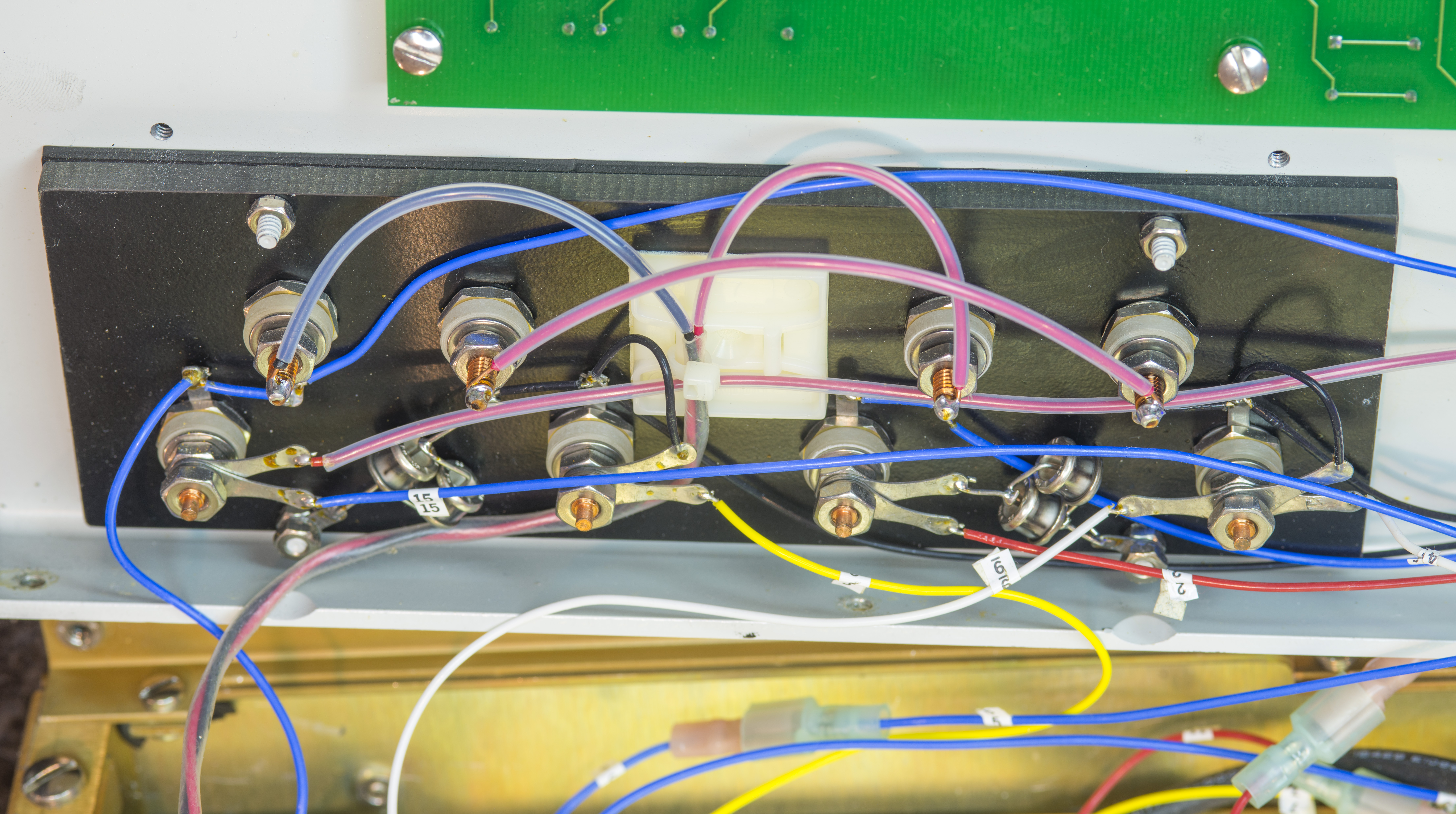
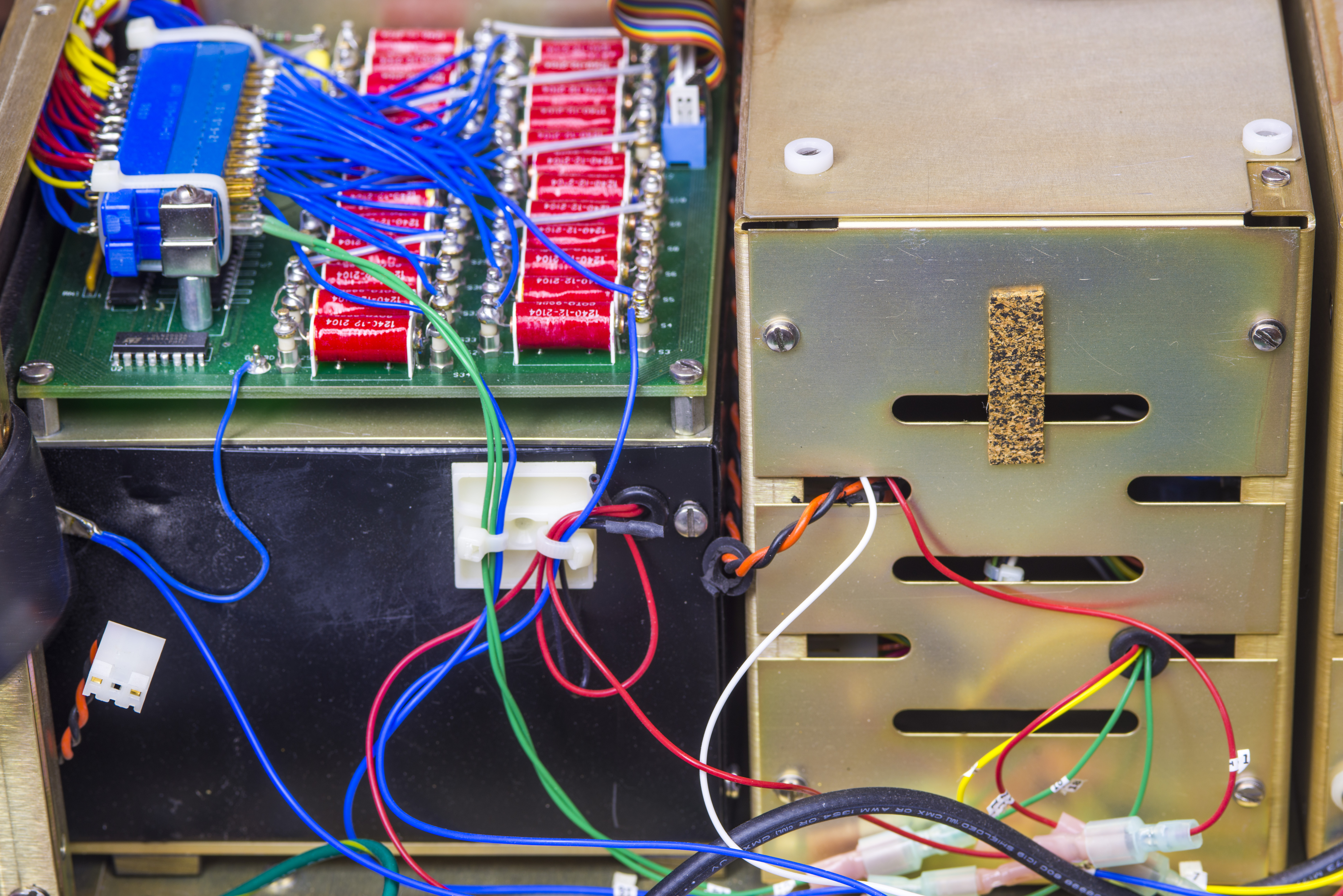
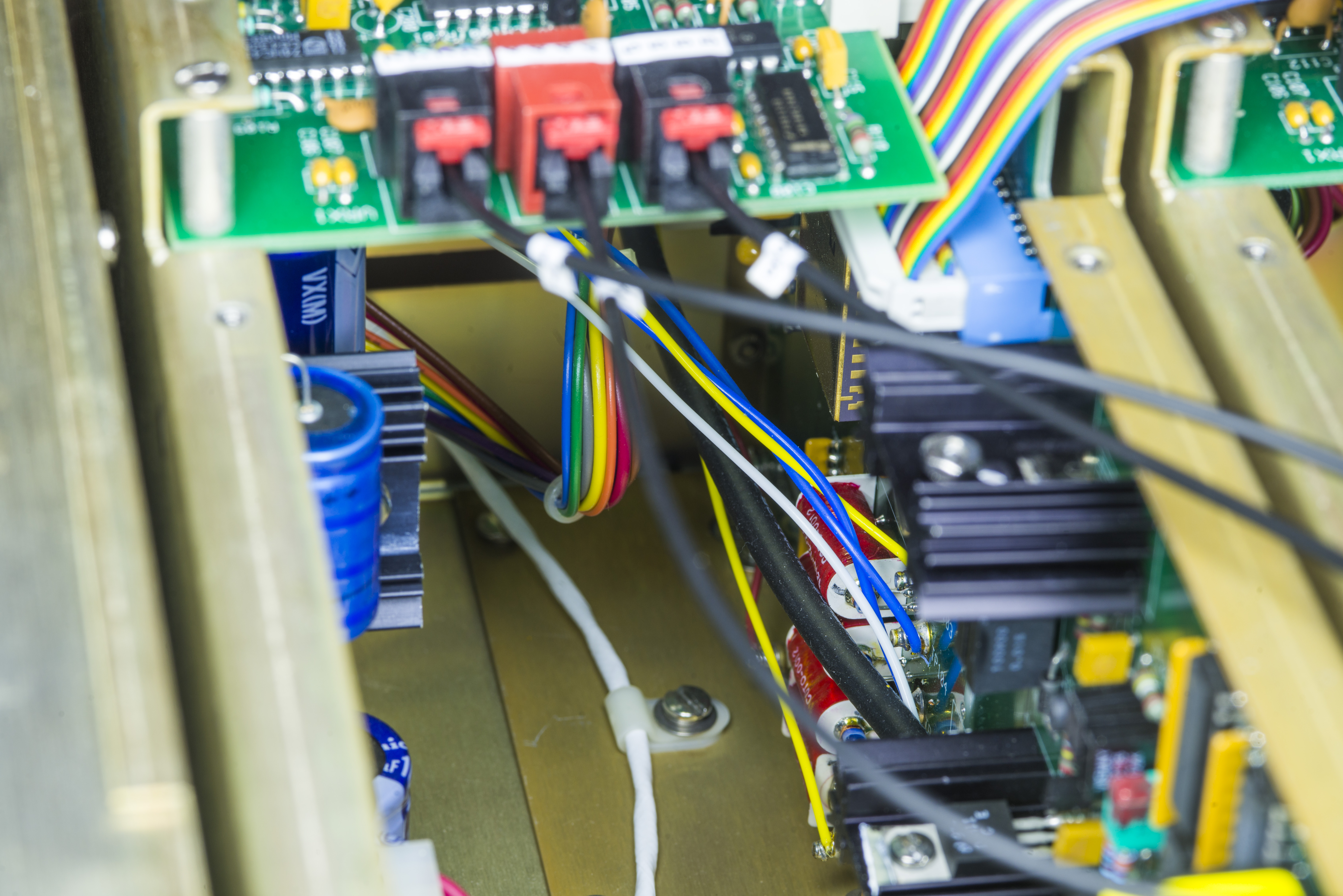
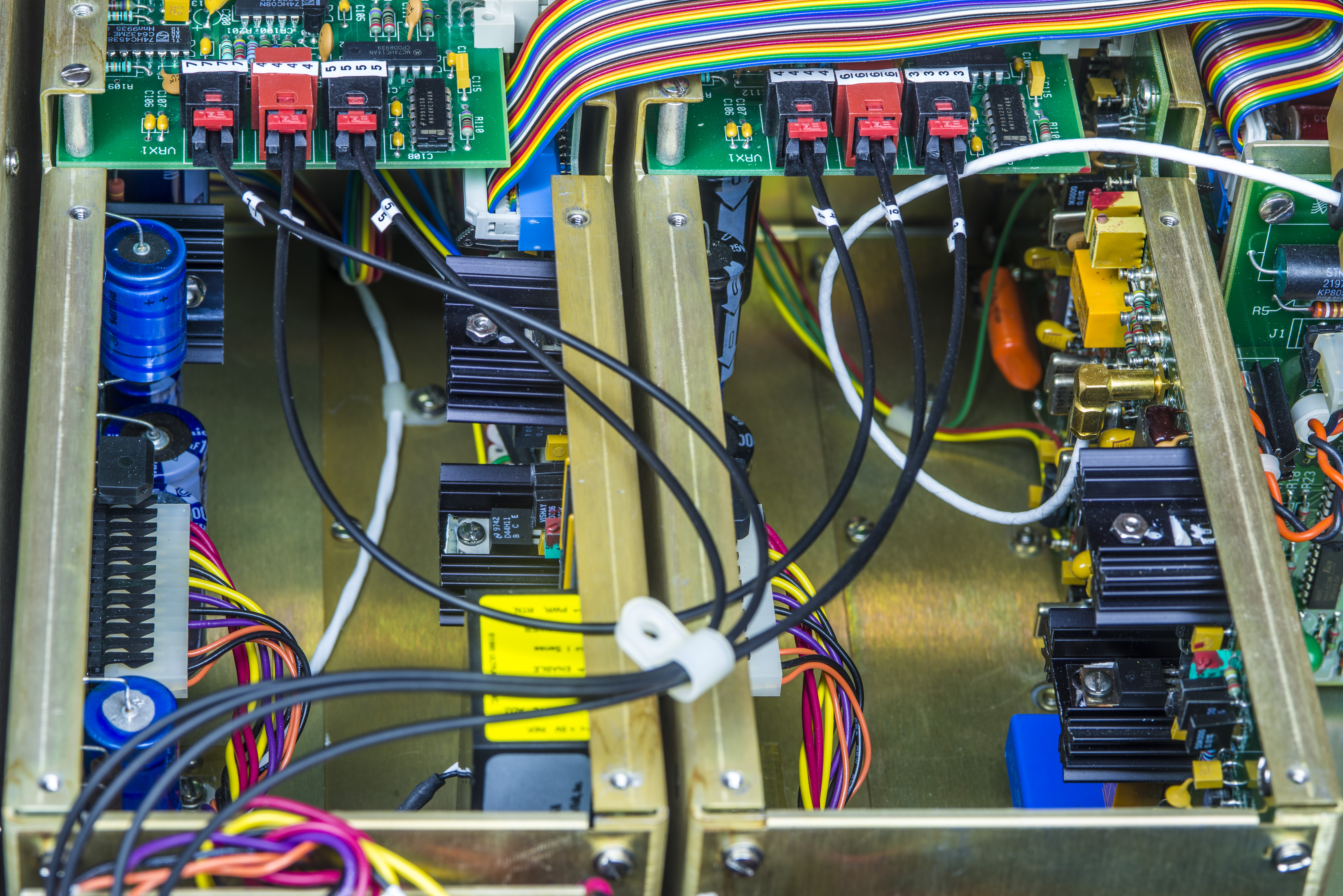
Moving on, there is whole lot of wiring around relay board with pretty COTO reed relays. Date code of manufacturing on them is 26 week 1999.
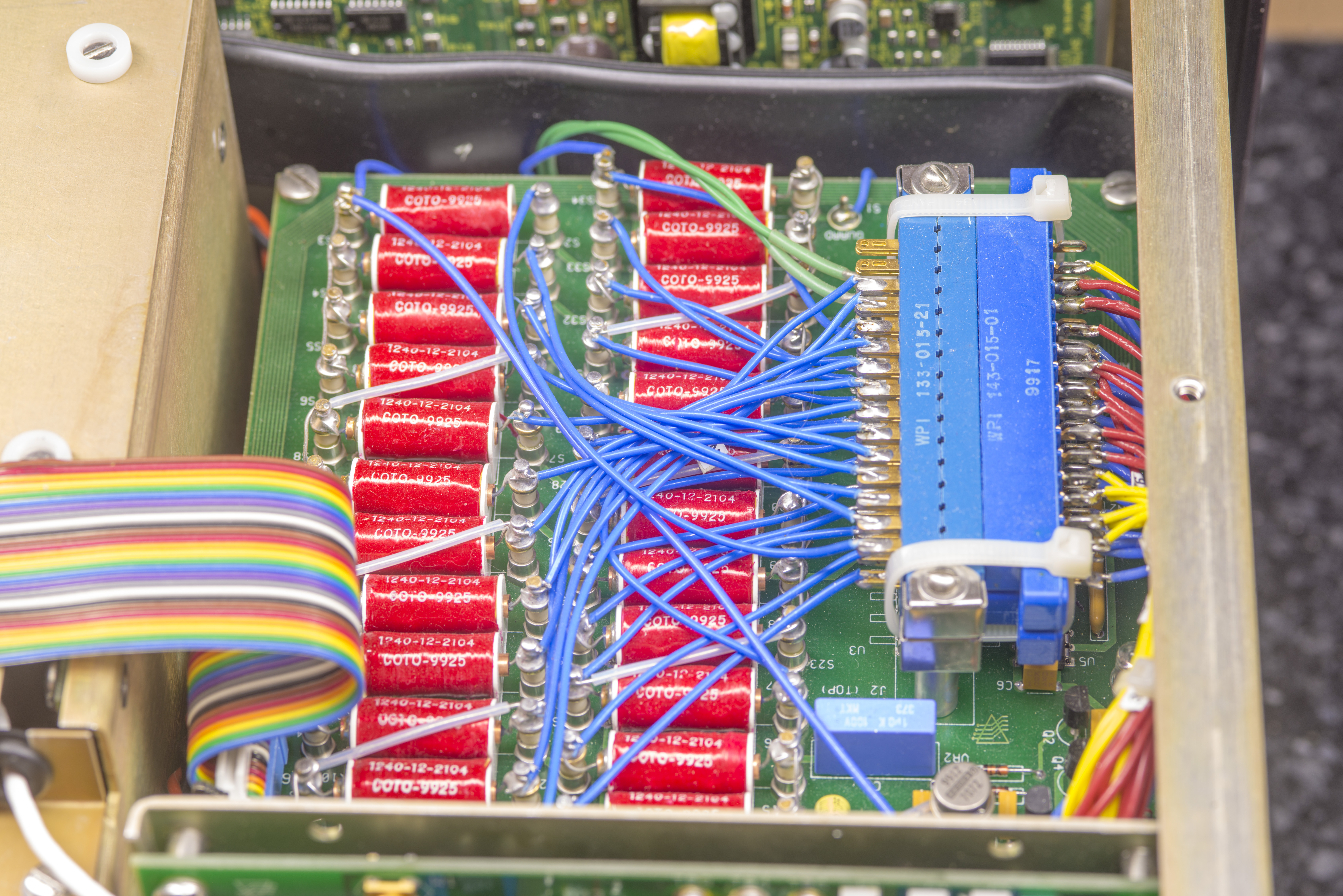
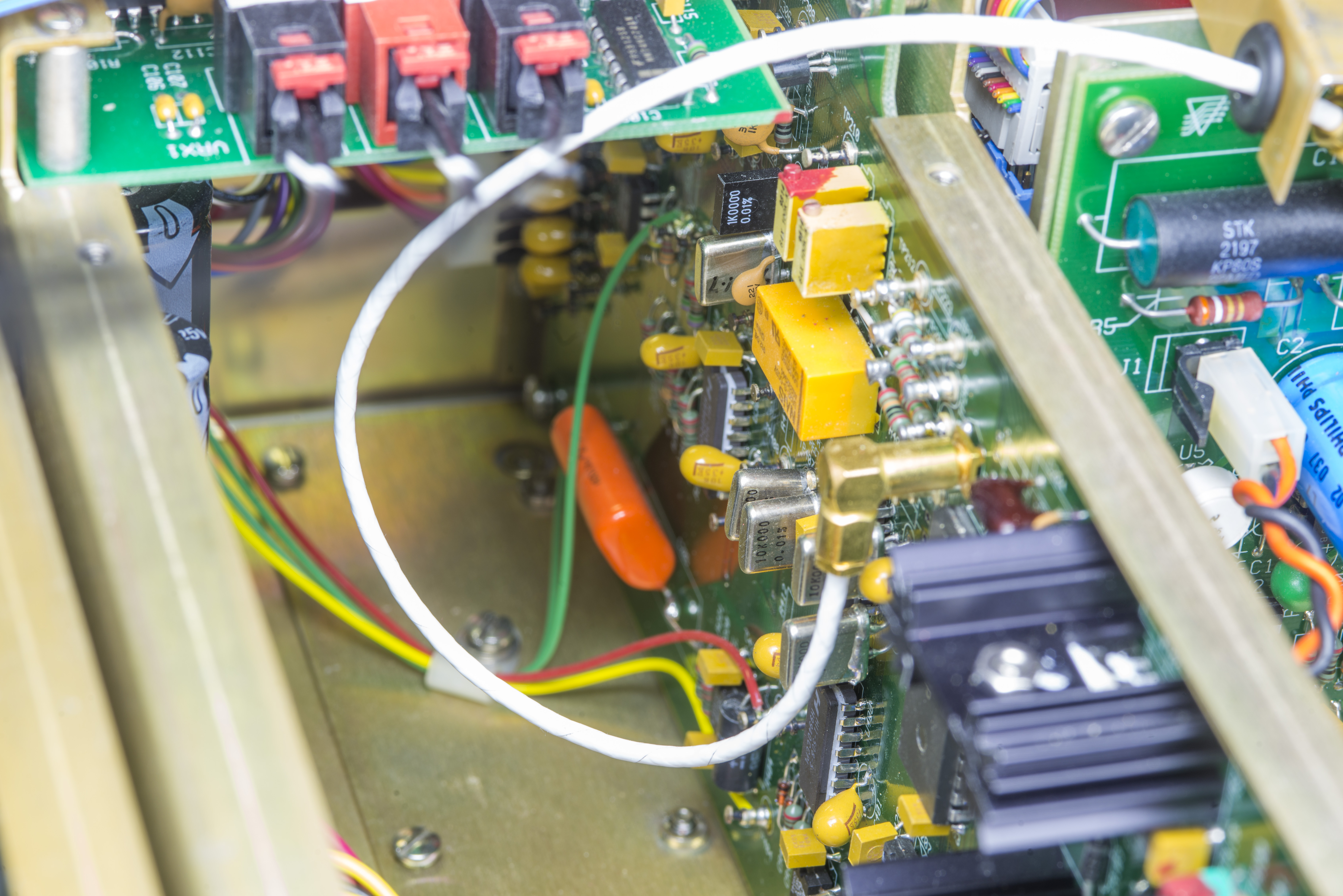
All these wires are from separate windings of ratio transformer. Transformer has 648 turns in standard resistor current loop and selectable turn number from 0 to 8747 for unknown resistor current loop. There are some additional windings for magnetic modulator and flux detector. This allows bridge operation with precise and stable ratio between Rx/Rs, where resolution is further increased by long-scale nanovolt detector. All these components talking to each other using fiber optics to ensure very good insulation and floated operation.
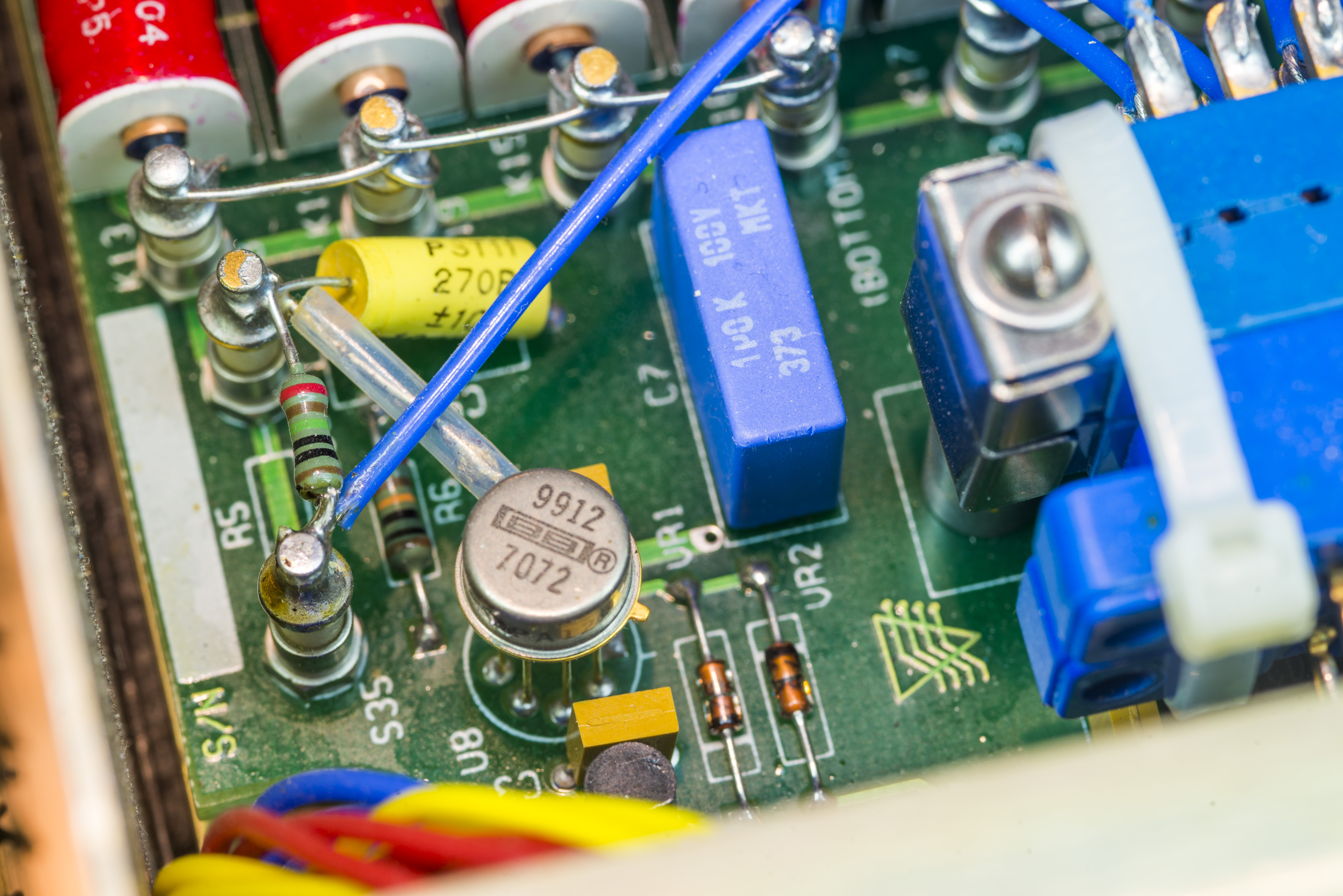
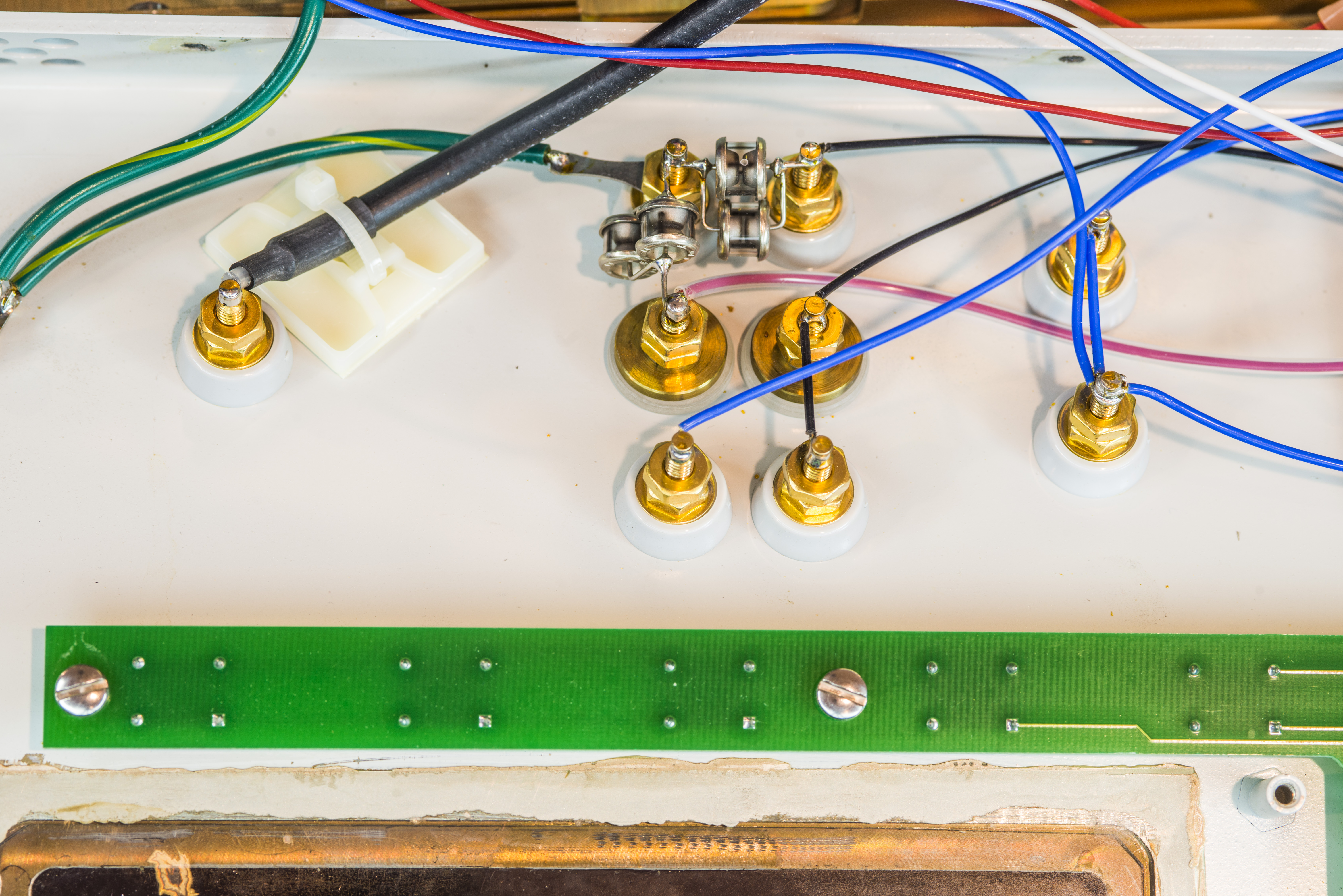
Some typical high-impedance wiring and PTFE standoffs can be found :).
On last photo we can see a culprit with VFD misalignment. It is missing a mount screw!

Not even just one screw but three, poor thing was hanging to it’s life on single screw. This was quick and easy fix by using three new 6/32” screws.
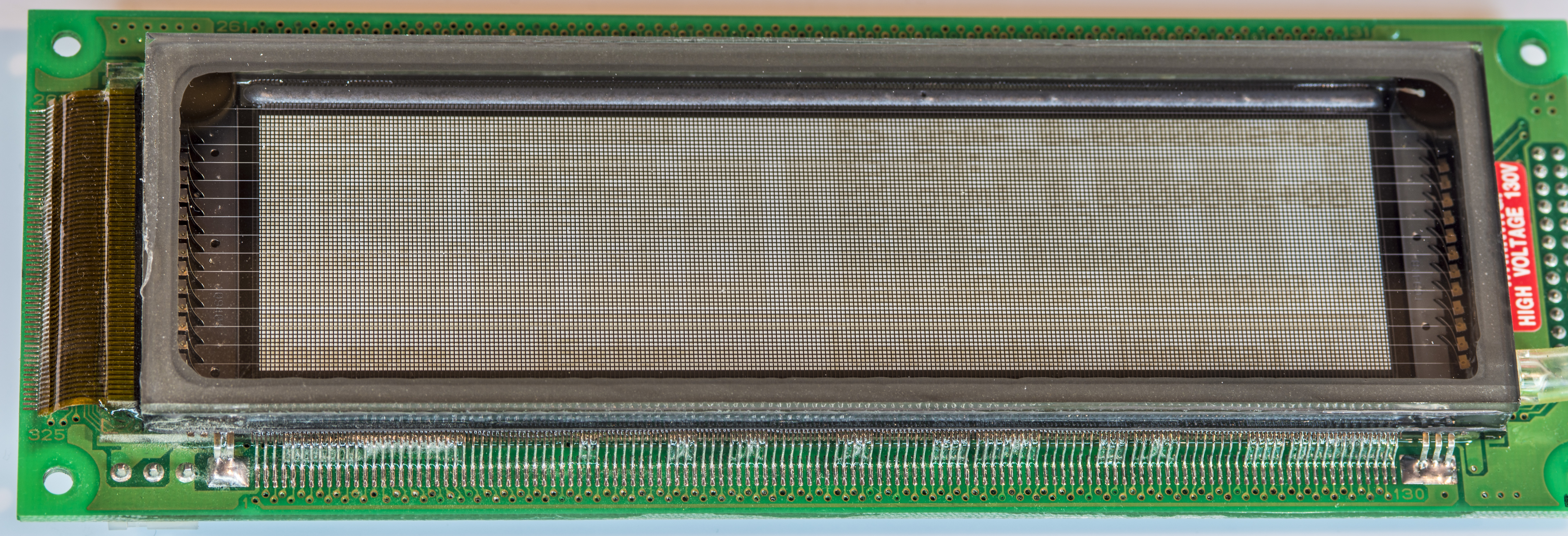
Display itself is standard Noritake Itron GU256×64-334, which uses +5V 2A supply and parallel bus for interfacing.
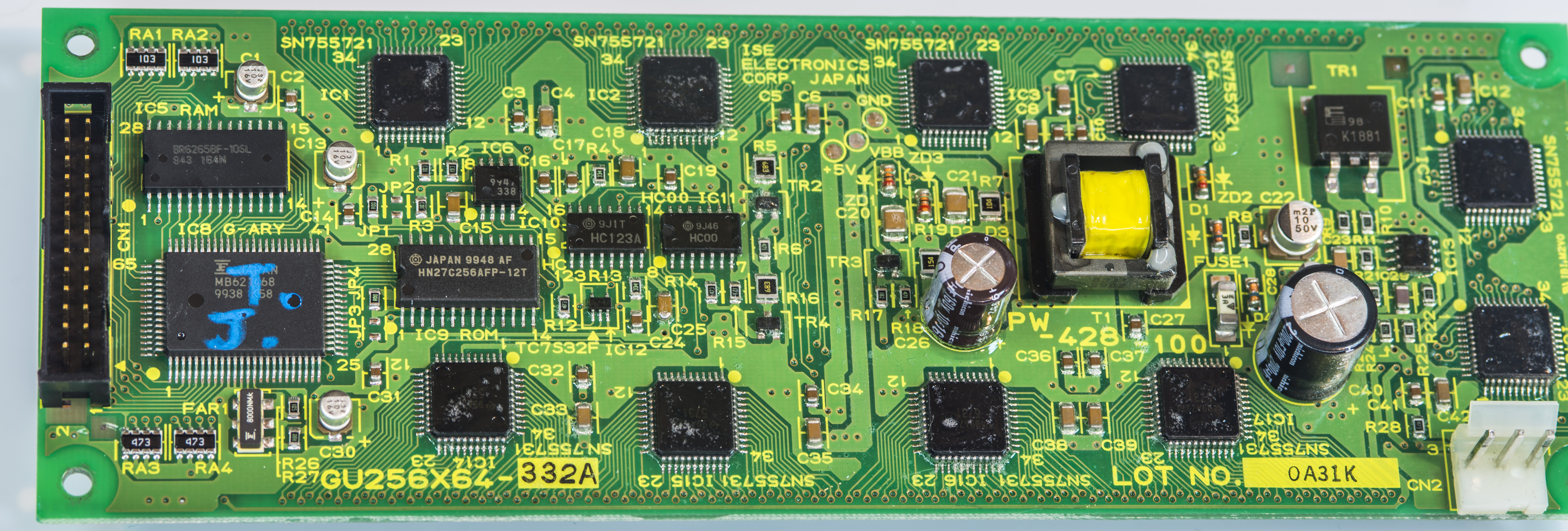
Bit surprising that there was no any metal shielding around VFD electronics, as there are high-voltage supplies on it to provide electrode voltages.

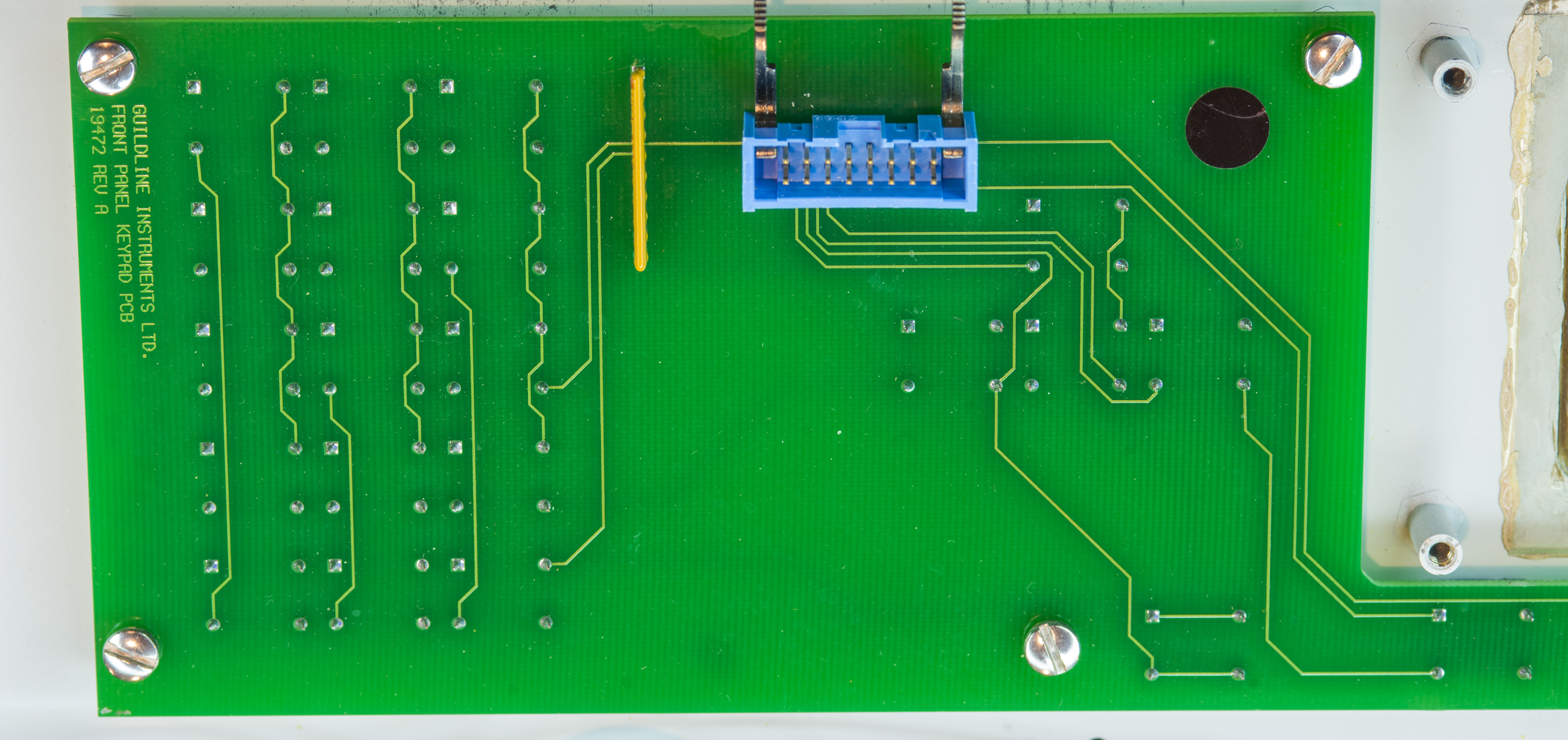
Power +5V for VFD provided by separate linear regulator PCB mounted on the chassis bottom.
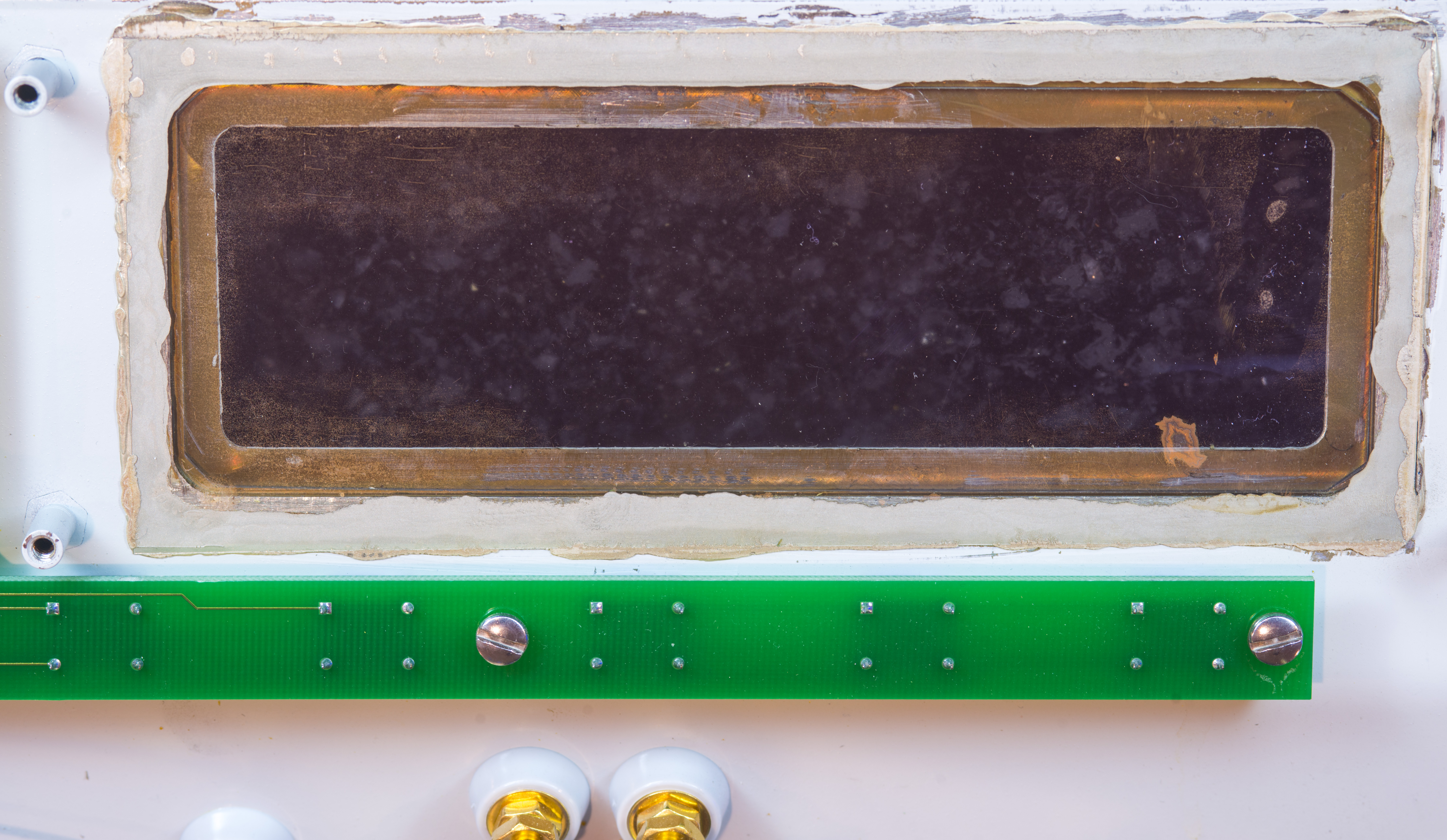
Display lens is conductive piece of glass mounted onto metal front panel frame with some kind of silver glue.
Magnetic modulator board is located behind relay and transformer box with it’s own little transformer.
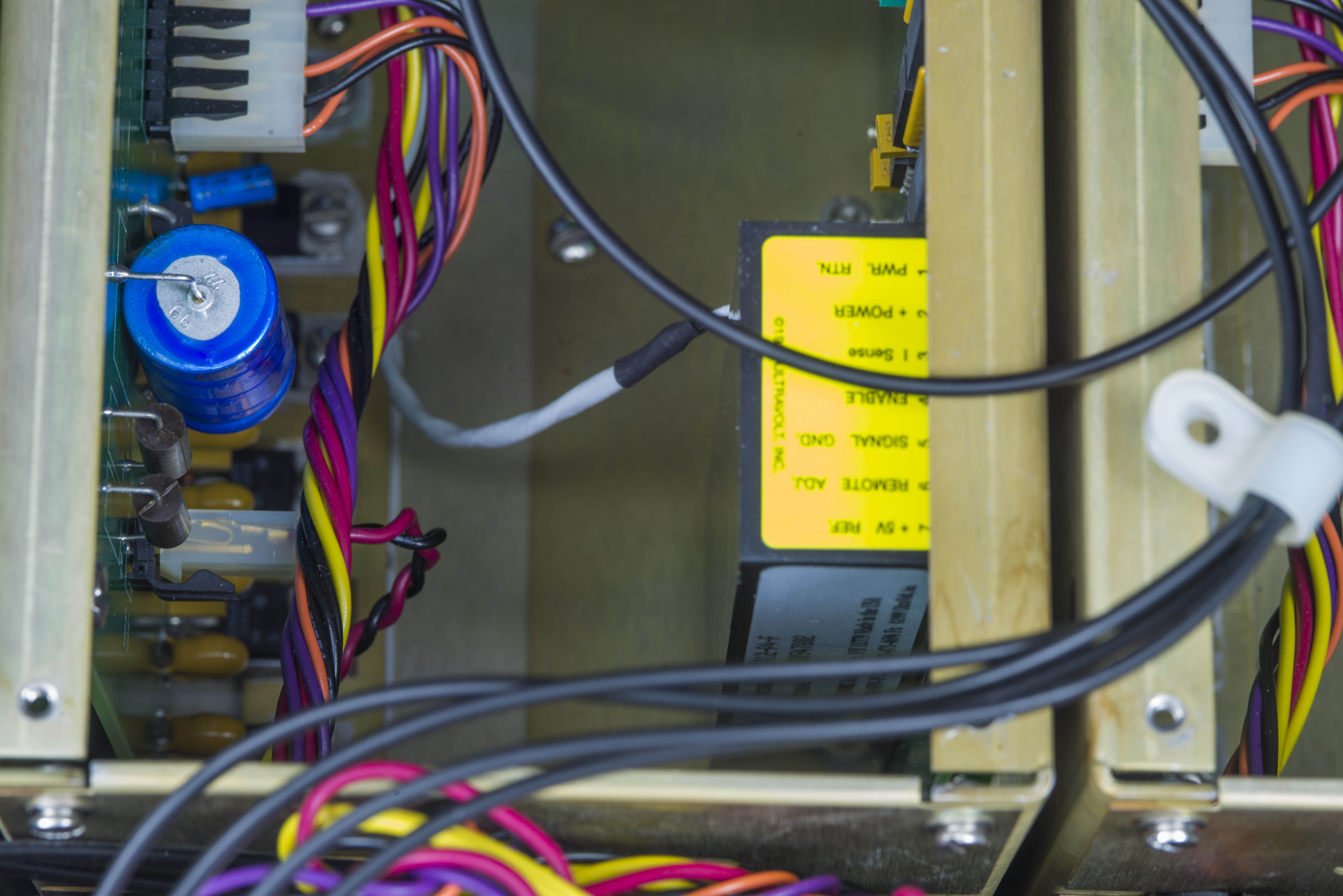
High voltage up to 990V provided by commercial DC-DC module, manufactured by UltraVolt, Model 1A12-P4-F . This 4 Watt DC/DC can supply 1kV at 4mADC current from +12V input and impements filter (output noise <1mV pk-pk) and offer 0.01% stability. Such sealed module also have monitor outputs and feedback sense inputs, allowing external control and adjustment.
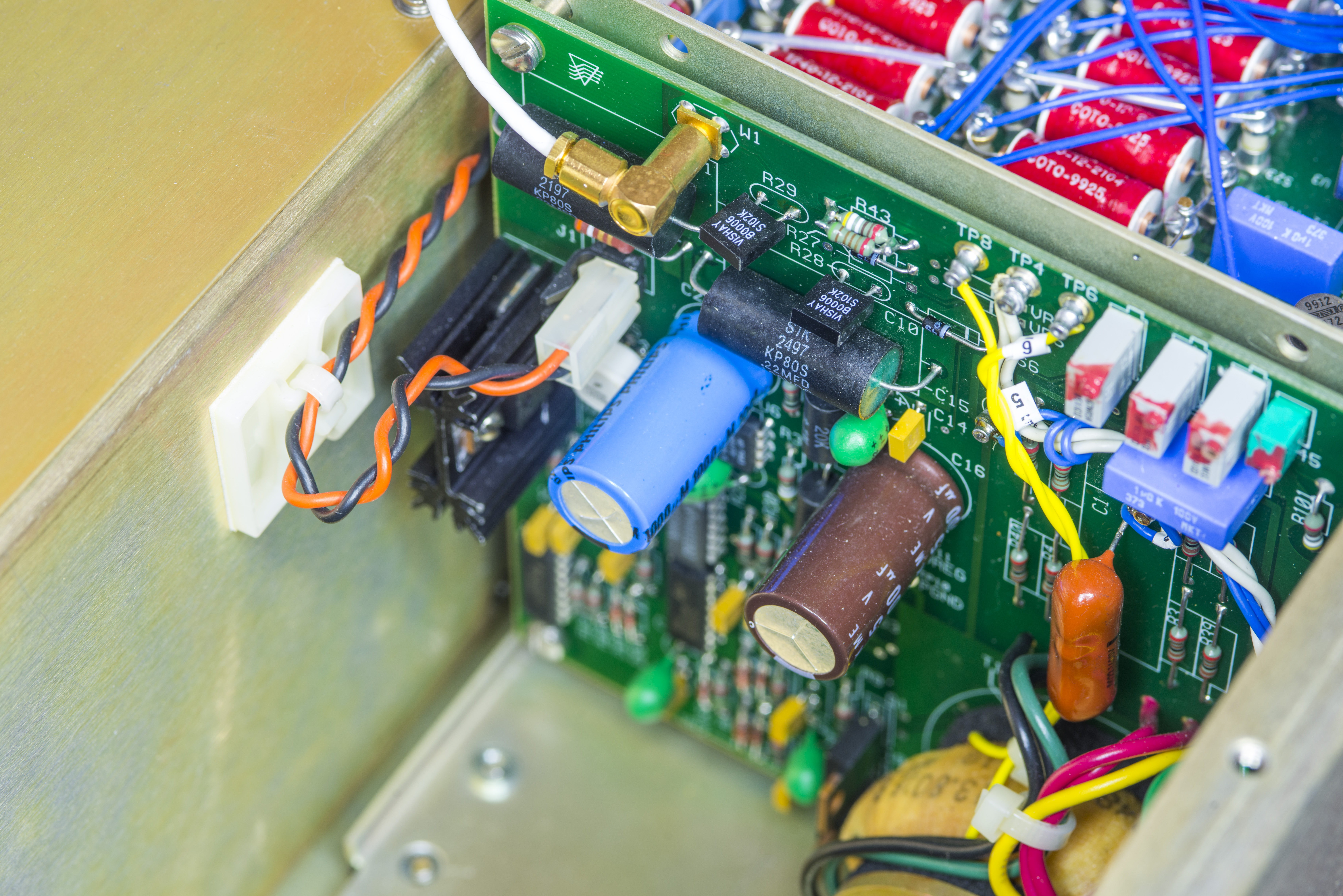
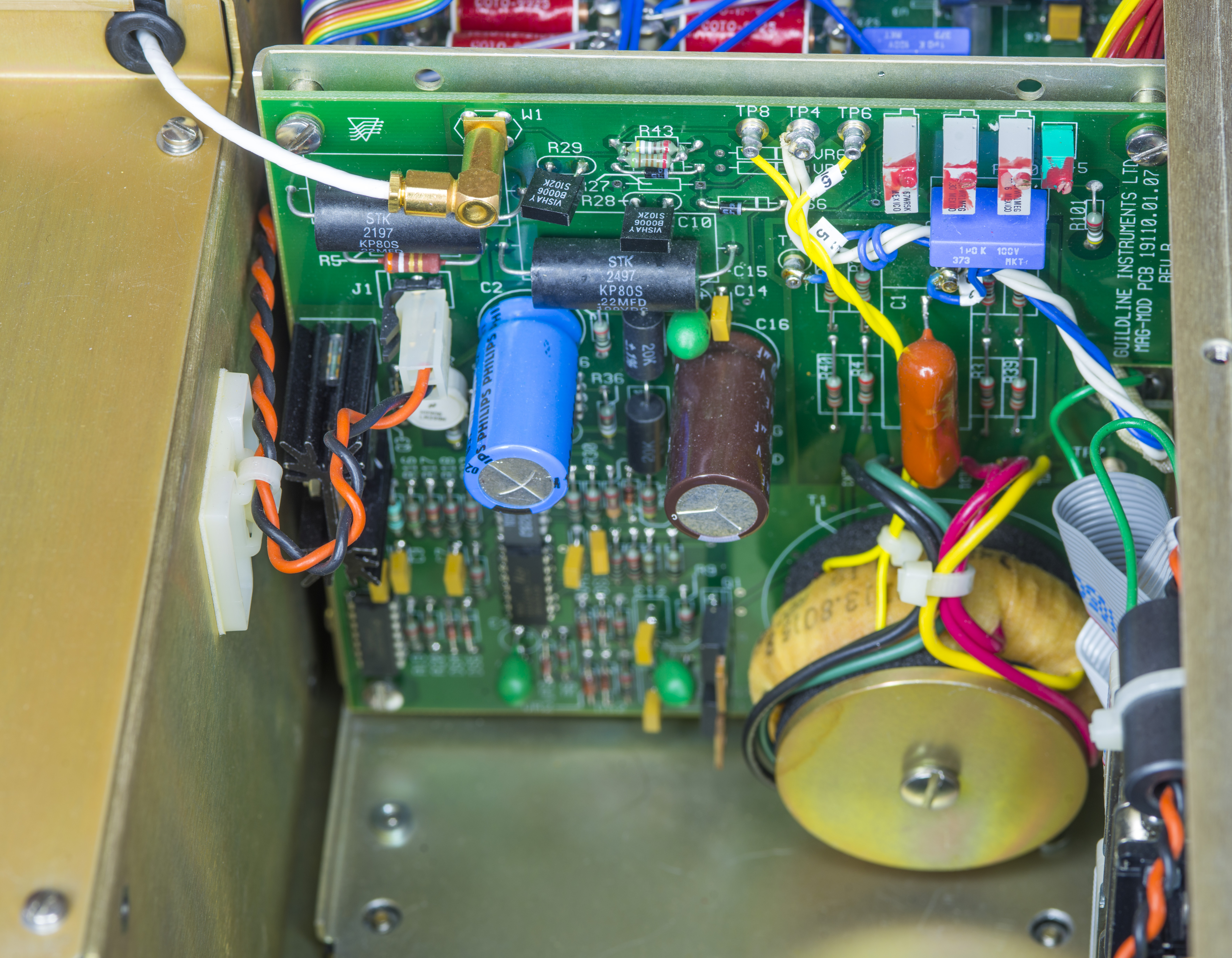
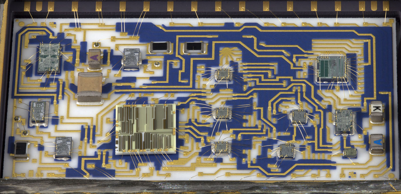
There are multiple VPG BMF resistors around the unit, both S102 epoxy and VHS hermetic type. But star of the current source board is indeed ceramic Analog Devices AD1139 18-bit current DAC . It’s gorgeous ceramic package with metal lid is installed in collet socket, so perhaps it was selected and tested by Guildline before being worthy for 6675A DCC.

In case you wonder about price of this high performance 18-bit DAC, to get few into next hobby project? Well, can’t afford such toys, being at $1706.58 USD in 100pcs qty. Can also get last one on Digikey if you don’t mind $2449.8 USD.
If one wondering about why package is so huge and expensive, Richi’s Lab have this extensive teardown and beautiful photographs of AD1139J sample. Just look at all this fine work, it brings a tear into any engineer eyes:
More to be added once we get replacement electrolytic capacitors to pimp up all of these 20 year old PCBs.
Guildline 6623 100A high current extender for low resistance measurements
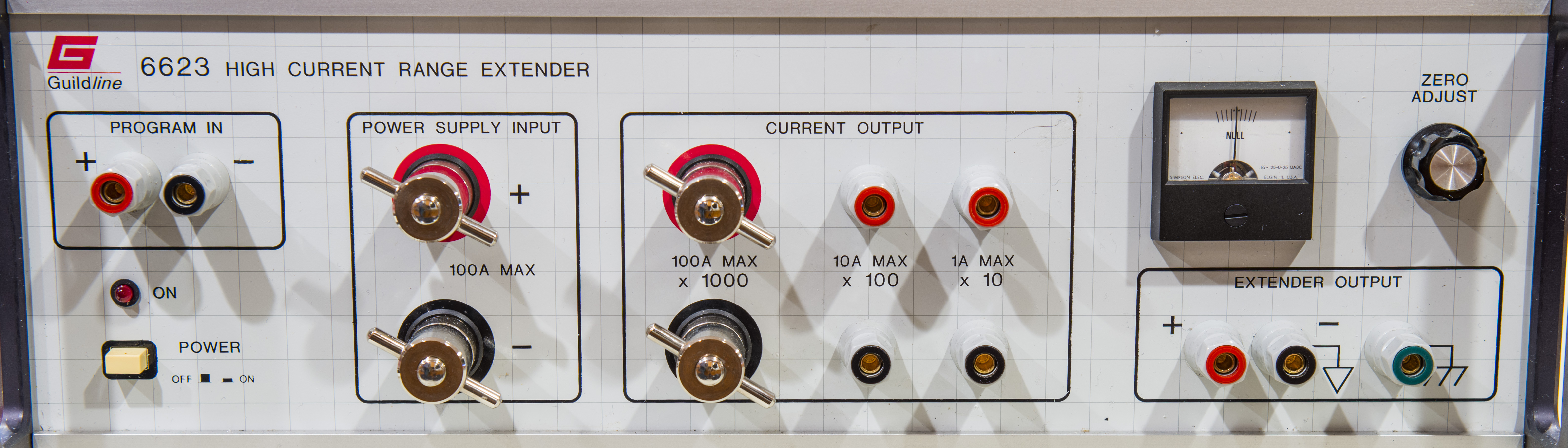
This unit acts as 100 Amp current reversal and current booster unit for 6675A. It has high-current flux comparator, high-current reversal switch for thermal EMF cancellation and some auxilary electronics. It does not generate high current by itself and must use external 100A low-noise power supply to operate.
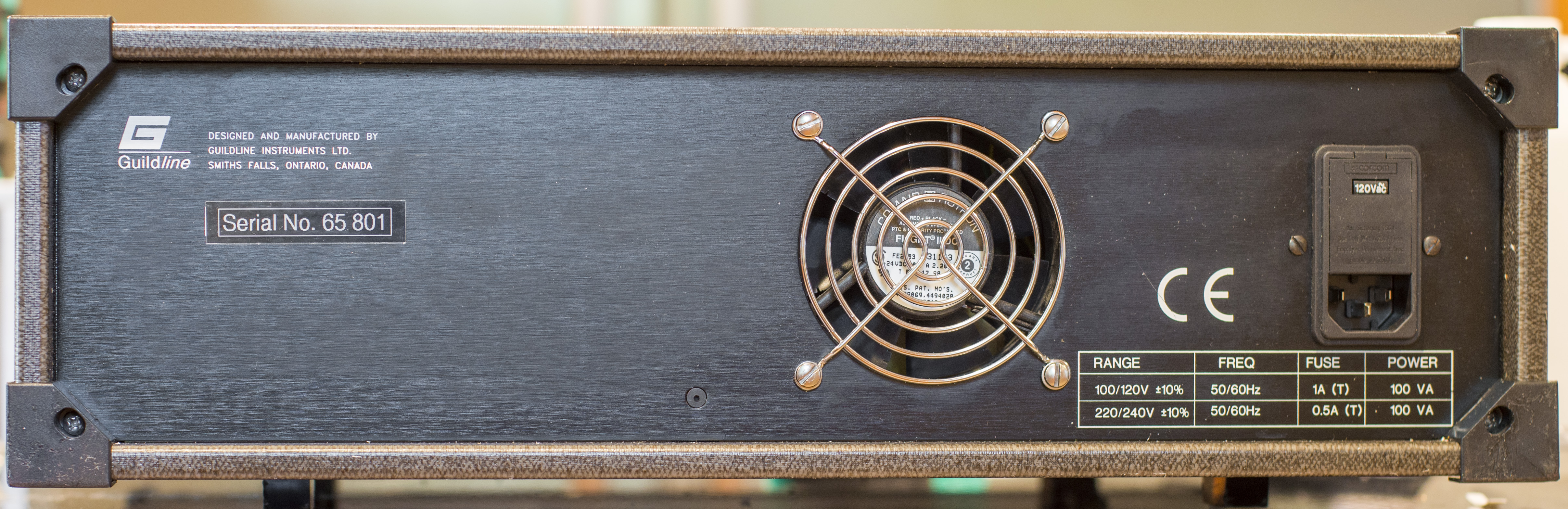
Back has just mains input jack with fuse and voltage selector and fan vent opening for cooling. 6623 operation is controlled by DCC bridge.
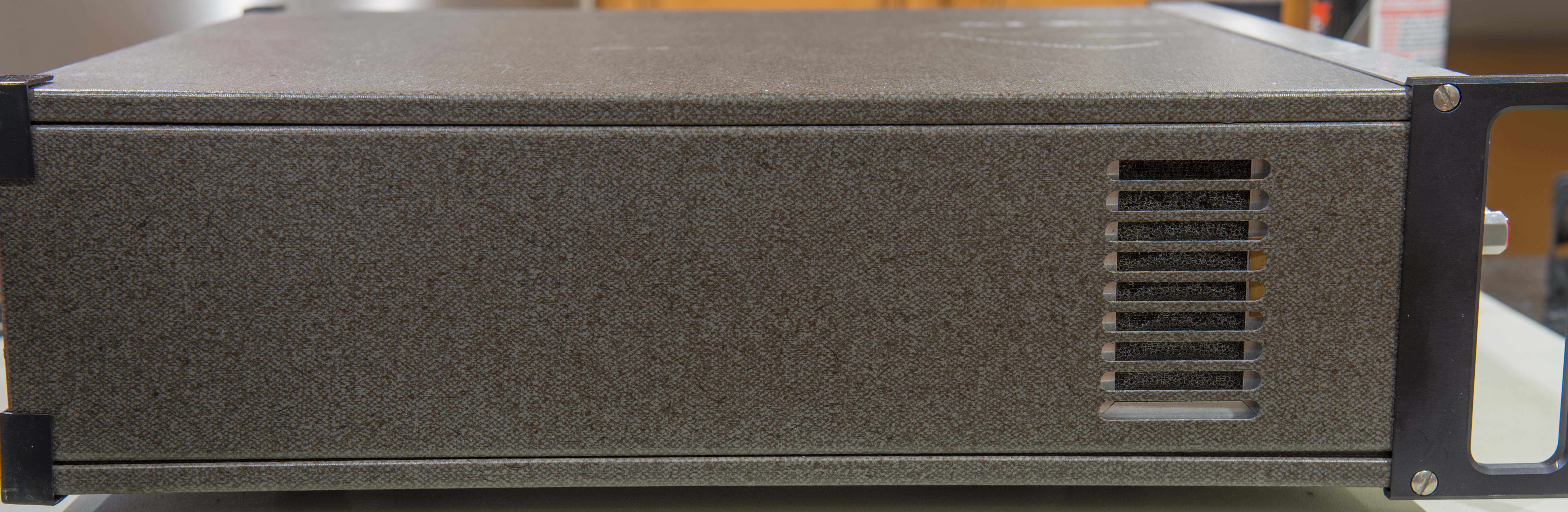
There is a vent on left side as well.


HP System power supply is used to provide needed current. Model 6031A is older unit, but well capable to provide up to 20V and 120A current with power limited at 1kW. PSU was previously tested with HP 6050A DC load mainframe.

At 100 amps wires must be big enough to support these levels of current. In this case two AWG 0/1 premade cables were used.

There was no easy way for DC load connection, so temporary wire bodge was installed to allow short-term supervised tests.
Now time to open up the 6623 extender cover and look inside.
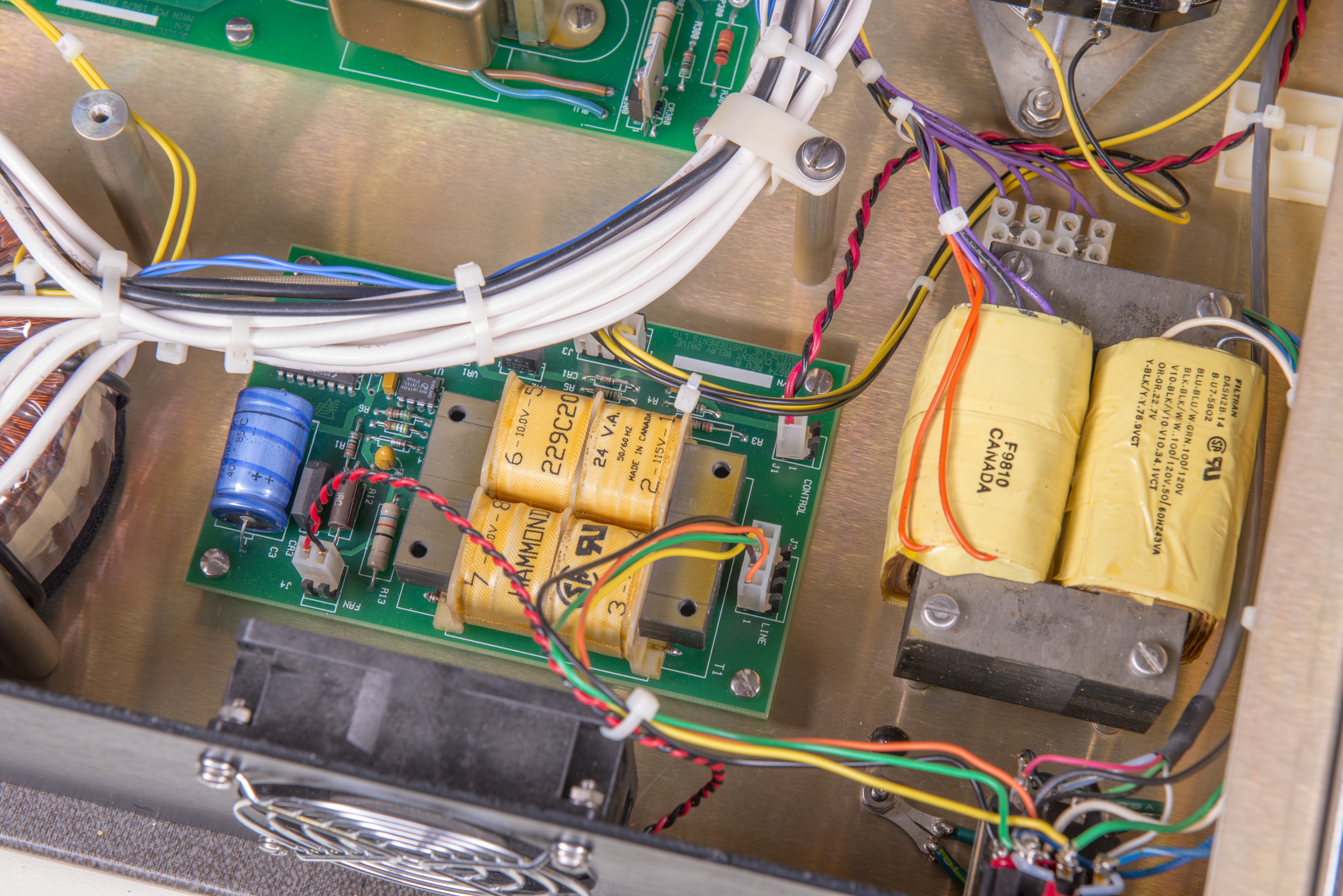
Overall very nice and clean construction with wires secured in place, good access to components thanks to modular approach.
Plenty of linear regulators and yellow/green tantalum friends to check around.
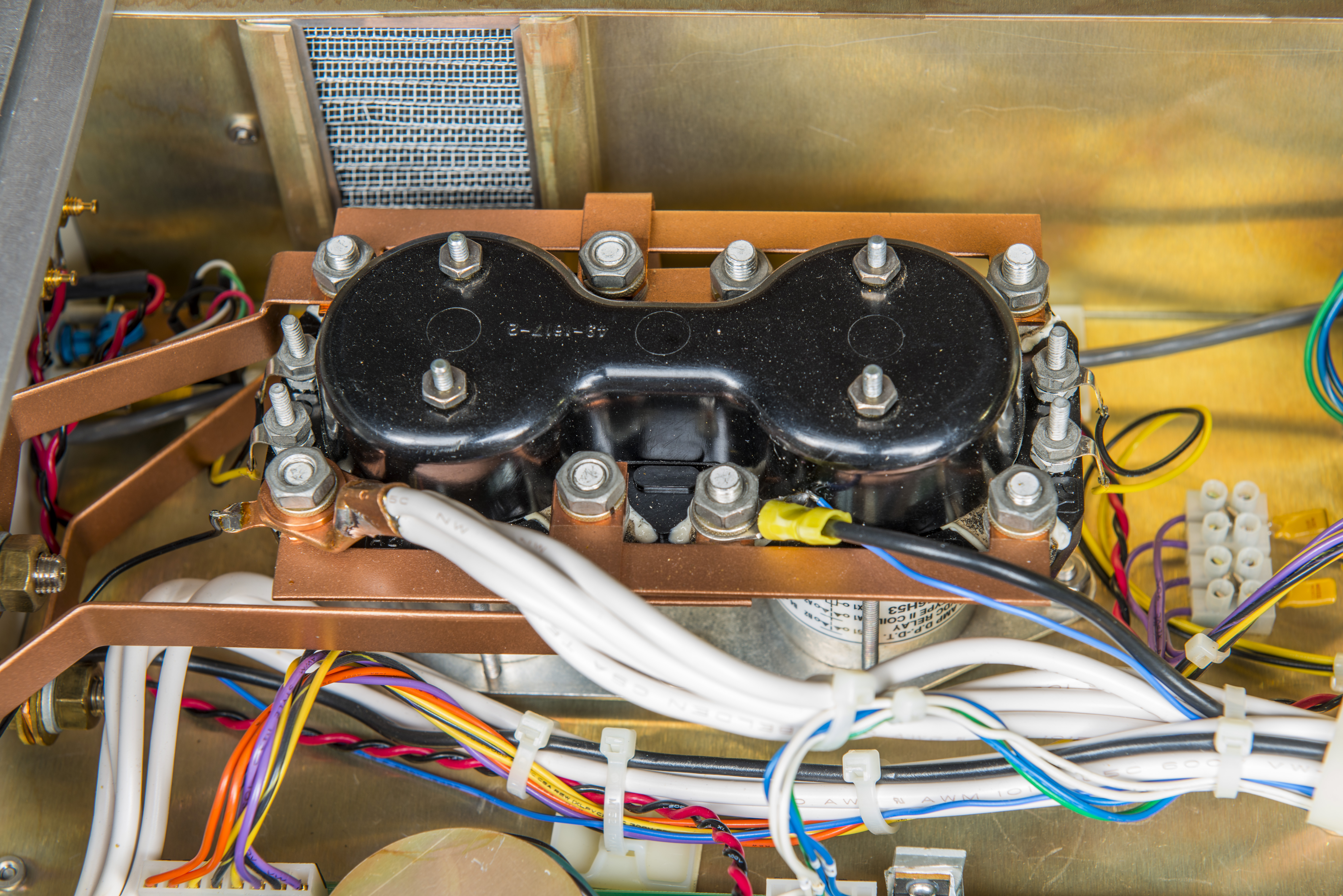
Huge DPDT relay with massive copper busbars aid current polarity reversal. Each relay have 24VDC control voltage. Auxilary 24VA 12V regulator PCBA provides power for a fan and relay coils.

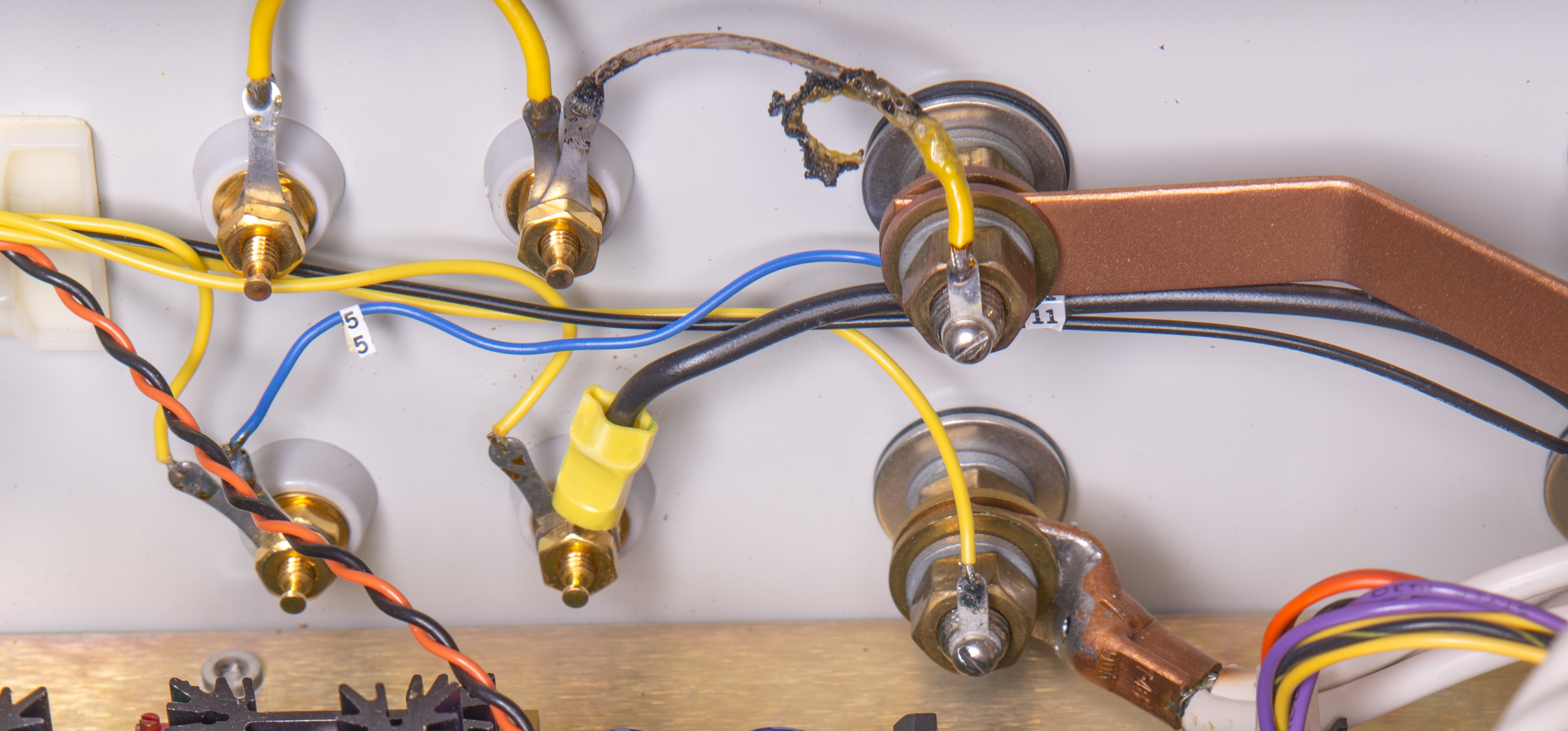
There is also obvious damage visible, wire between current output 100A and 10A terminal was burned to crisp. Perhaps previous user used 10A output jack while much higher 100A current was applied. Should be easy to repair and replace.
TBD…
Verification of Fluke 5700A’s resistance artifact calibration with 6675A DCC Bridge.
TBD…
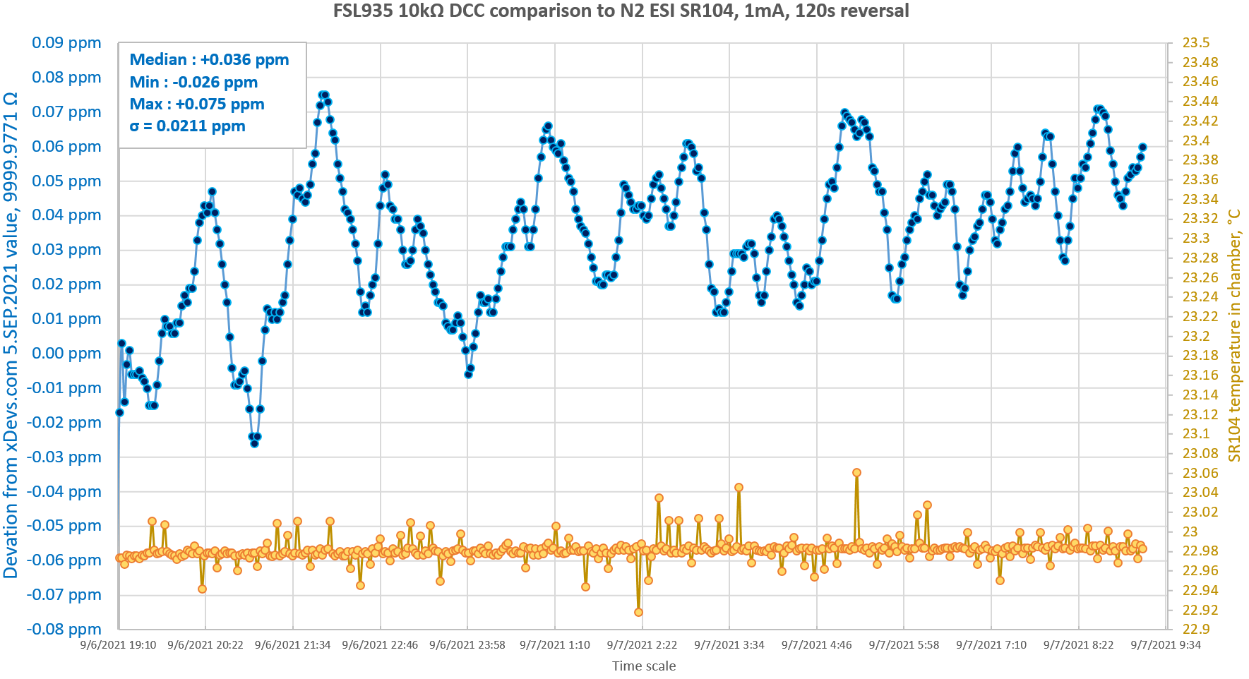
Verification of ovenized Fluke SL935 1 Ω/10 kΩ with bridge.
TBD…
High resistance transfers using bridge.
Projects like this are born from passion and a desire to share how things work. Education is the foundation of a healthy society - especially important in today's volatile world. xDevs began as a personal project notepad in Kherson, Ukraine back in 2008 and has grown with support of passionate readers just like you. There are no (and never will be) any ads, sponsors or shareholders behind xDevs.com, just a commitment to inspire and help learning. If you are in a position to help others like us, please consider supporting xDevs.com’s home-country Ukraine in its defense of freedom to speak, freedom to live in peace and freedom to choose their way. You can use official site to support Ukraine – United24 or Help99. Every cent counts.
Modified: Oct. 3, 2021, 8:20 p.m.