Contents
- Intro
- Disclaimer
- Manuals references
- Initial inspection
- Repair workflow
- Firmware
- Calibration January 17, 2016
- Calibration February 10, 2019
- Restoration summary
Intro
Following recent trend with Hewlett-Packard equipment repair, welcome new article for more popular bench DMM repair worklog. One of EEVBlog forum members acquired broken 6½-digit bench DMM, classic HP 34401A. This model was designed in same era as instruments like HP 3458A, and using similar topology to most of 6½-digit multimeters, such as Keithley 2000. In this article initial diagnostics, repair attempt and calibration will be covered.
34401A features:
- 6½-digit resolution
- 10 measurement functions: DC/AC voltage, DC/AC current, 2- and 4-wire resistance, diode, continuity, frequency, period
- Basic accuracy: 0.0035% DC, 0.06% AC
- 1000 V max voltage input, 3 A max current input
- 1000 readings/second
- 512 reading memory
Unlike modern Keysight’s 3446x/34470A which all use big fancy LCD, this meter have nice old-school warm tube VFD-type display, which is visible from any angle and have great contrast.
Disclaimer
Redistribution and use of this article or any images or files referenced in it, in source and binary forms, with or without modification, are permitted provided that the following conditions are met:
- Redistributions of article must retain the above copyright notice, this list of conditions, link to this page (/fix/hp34401a/) and the following disclaimer.
- Redistributions of files in binary form must reproduce the above copyright notice, this list of conditions, link to this page (/fix/hp34401a/), and the following disclaimer in the documentation and/or other materials provided with the distribution, for example Readme file.
All information posted here is hosted just for education purposes and provided AS IS. In no event shall the author, xDevs.com site, or any other 3rd party, including HP/Agilent/Keysight be liable for any special, direct, indirect, or consequential damages or any damages whatsoever resulting from loss of use, data or profits, whether in an action of contract, negligence or other tortuous action, arising out of or in connection with the use or performance of information published here.
If you willing to contribute or add your experience regarding HP/Agilent/Keysight instruments repairs or provide extra information, you can do so following these simple instructions
Manuals references
Keysight 34401A Digital Multimeter – Datasheet
Keysight 34401A, 34405A, 34410A, and 34411A Digital Multimeters – Product fact sheet
Compatibility and Differences – 34461A and 34401A Digital Multimeters
Agilent 34401A Multimeter – Product overview
And most valuable in this repair:
Agilent 34401A 6½ Digit Multimeter – Service manual, with schematics
Initial inspection
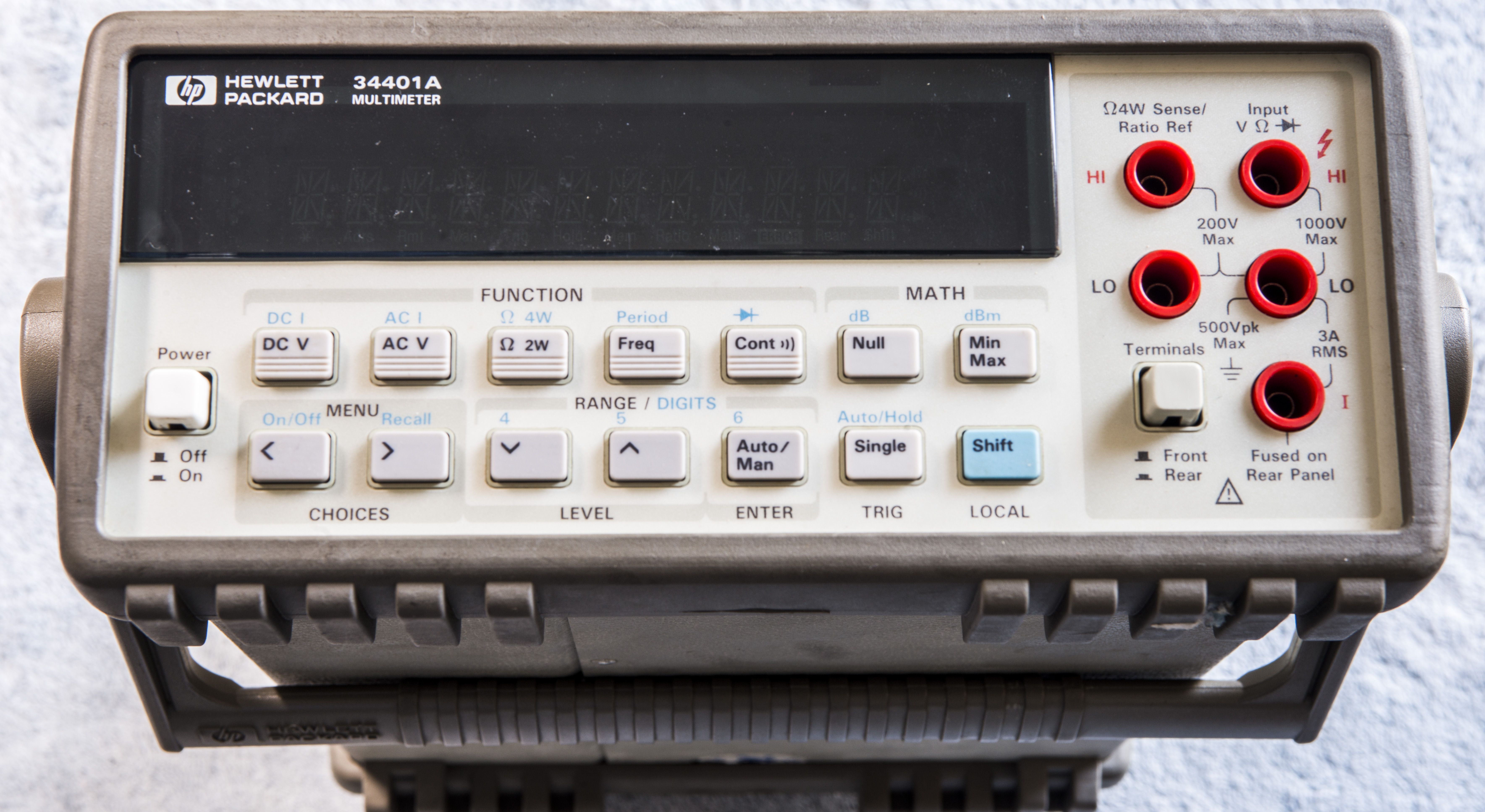
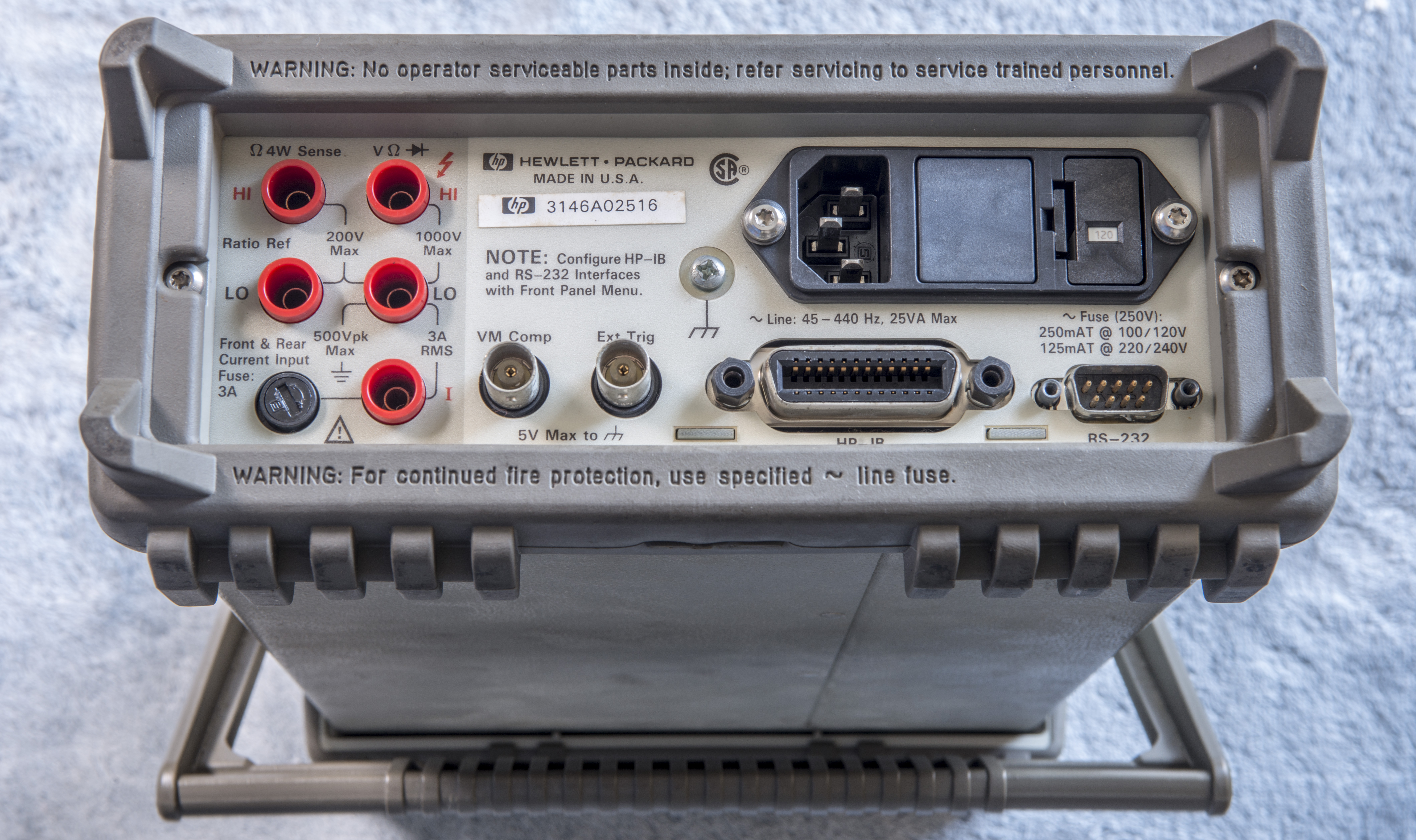
Image 1,2: HP 34401A front and rear.
DMM is very dirty outside, and definitely need good deal of scrubbing with alcohol and cleaning.
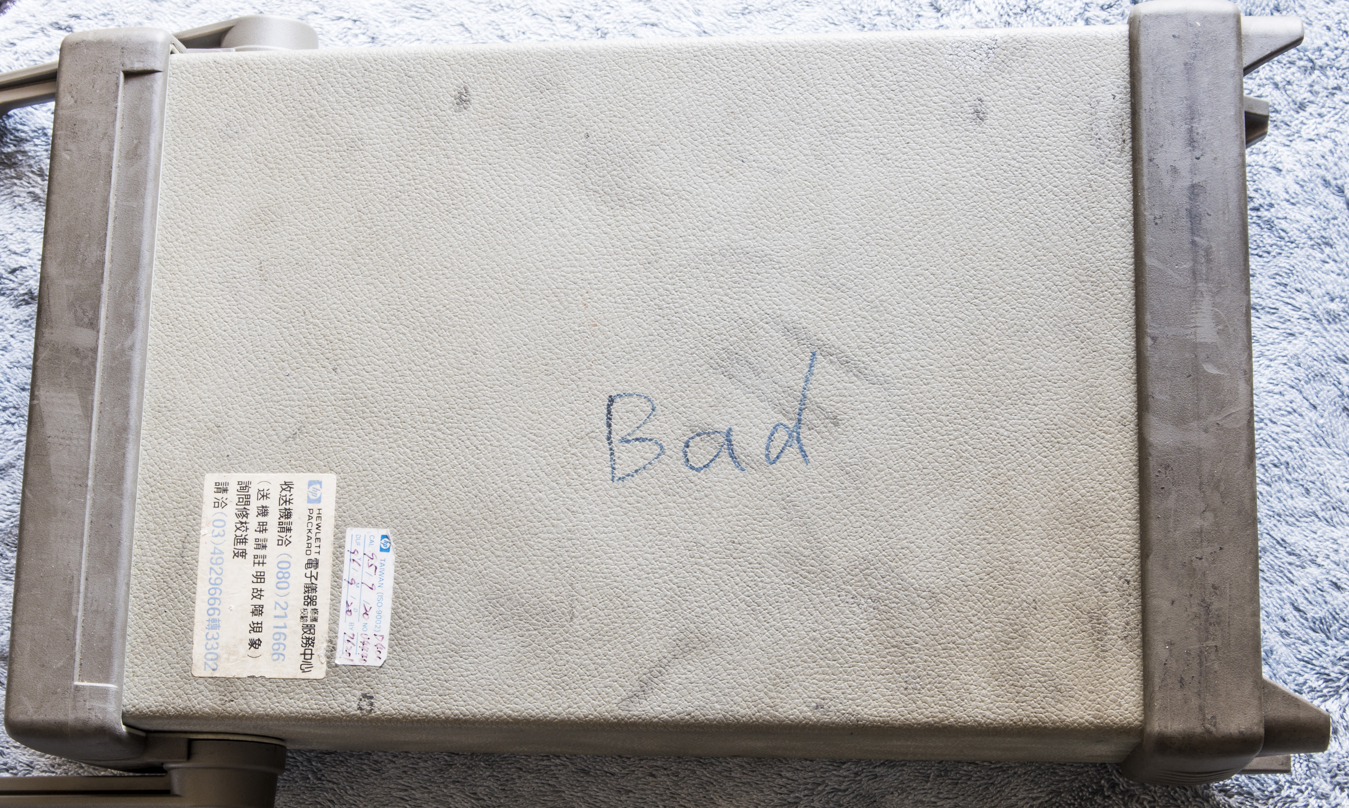
Image 3: HP 34401A top cover marking “BAD”.
Meter does power on, VFD screen lit up and keypad working normally. But readings are incorrect, +10VDC supplied to input showing as 3.607VDC, and changes to 0.0000VDC if change range to 100 or 1kV. Ohms reading nothing as well, and ACV reads just 28µV no matter what is supplied on input.
Selftest brings only single error – ERROR 1 : 604, which is related to A/D:
ERROR 604 : A/D slope convergence failed The dc section is configured to the measure zero state (MZ) in the 10 V range. This test checks whether the ADC integrator produces nominally the same number of positive and negative slope decisions (±10%) during a 20 ms interval.
Usually errors of this kind not good, as multi-slope integrating A/D converter used in such DMMs is often using custom chips and selected components, but let’s hope it’s something simple as power supplies or dead resistor/opamp. We will go into details of A/D operation during debug in next section.
Let’s open and see what’s inside.
Repair workflow
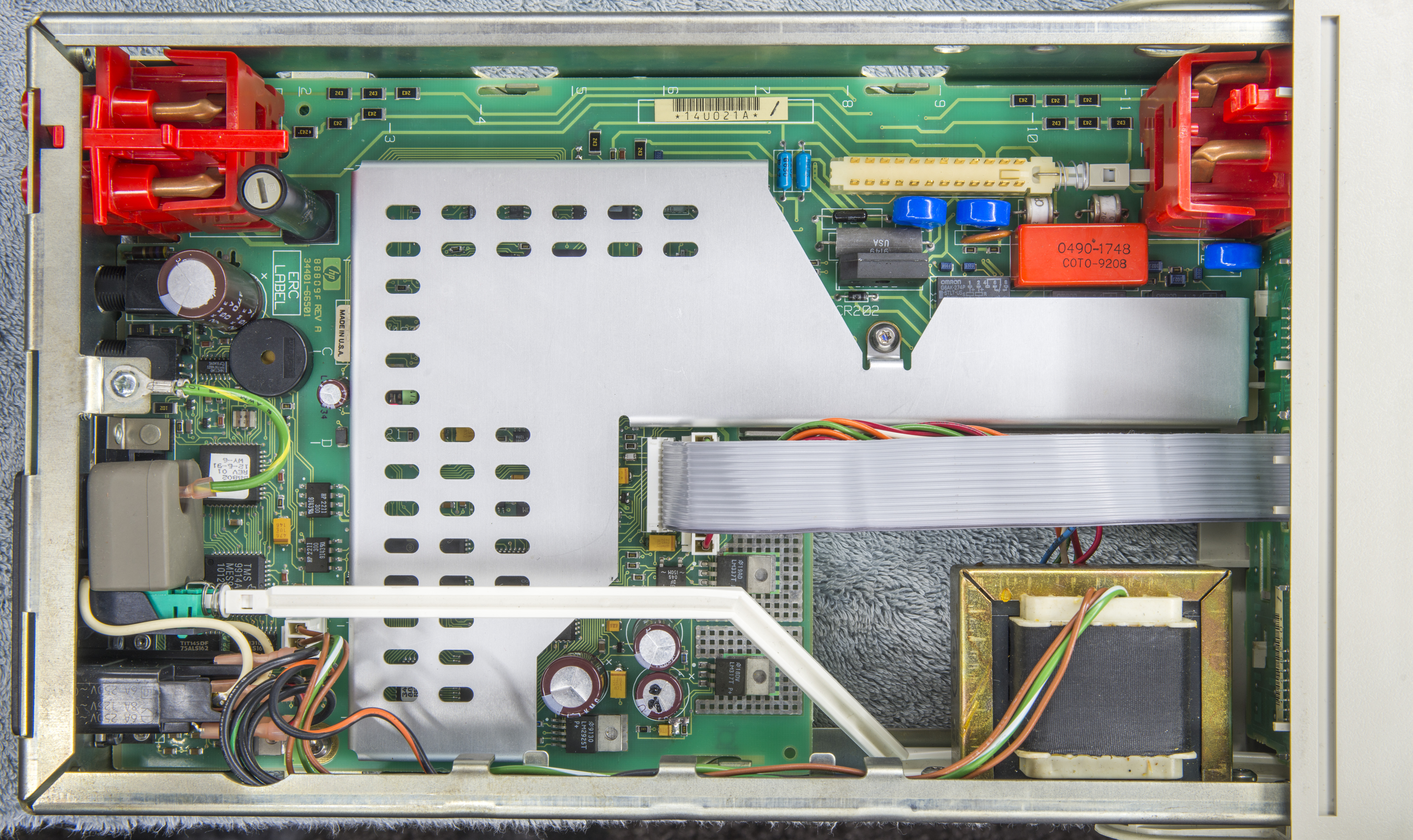
Image 4: HP 34401A after cover removed.
PCB and all inner in DMM are very clean, no spider webs or dust anywhere. That is likely due to absence of fan or vent holes anywhere in the chassis. 34401A take only ~10W from mains power, and does not require active airflow inside. It’s also reason why lot of engineers like this instrument, it’s quiet, stable and have solid performance.
Removed front panel, to get easier access to mainboard. It’s similar to other HP instruments, just slides at sides by removing locking mechanisms and two screws.
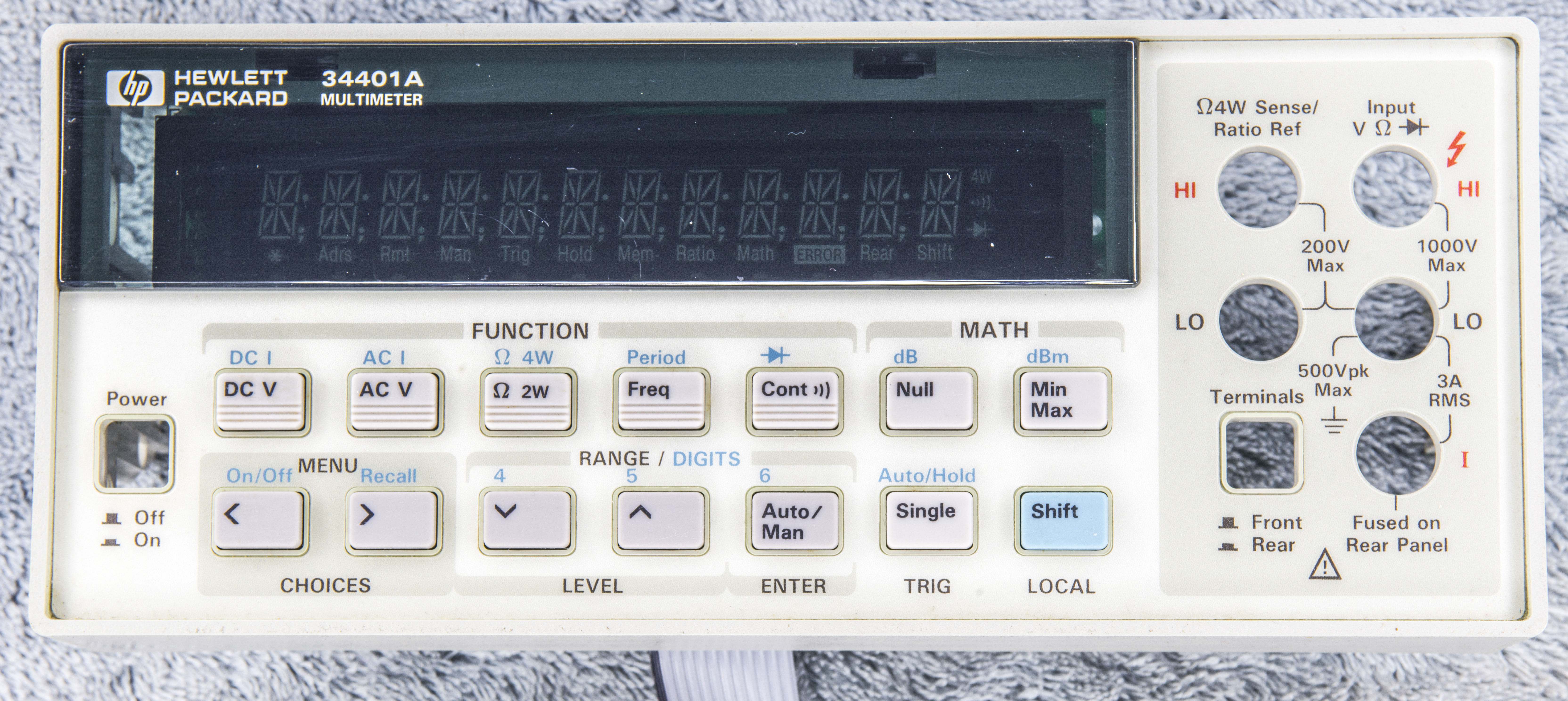

Image 5,6: HP 34401A front panel removed, front and rear.
Front panel board 34401-66502 REV.A have ERC code 3140, and is made in USA. No problem with it, so I’ll not remove it from the front panel bezel. FP connects to main board thru semi-rigid ribbon cable, same as 33120A ARB generator. I personally don’t like this connection type, as it’s not that reliable.
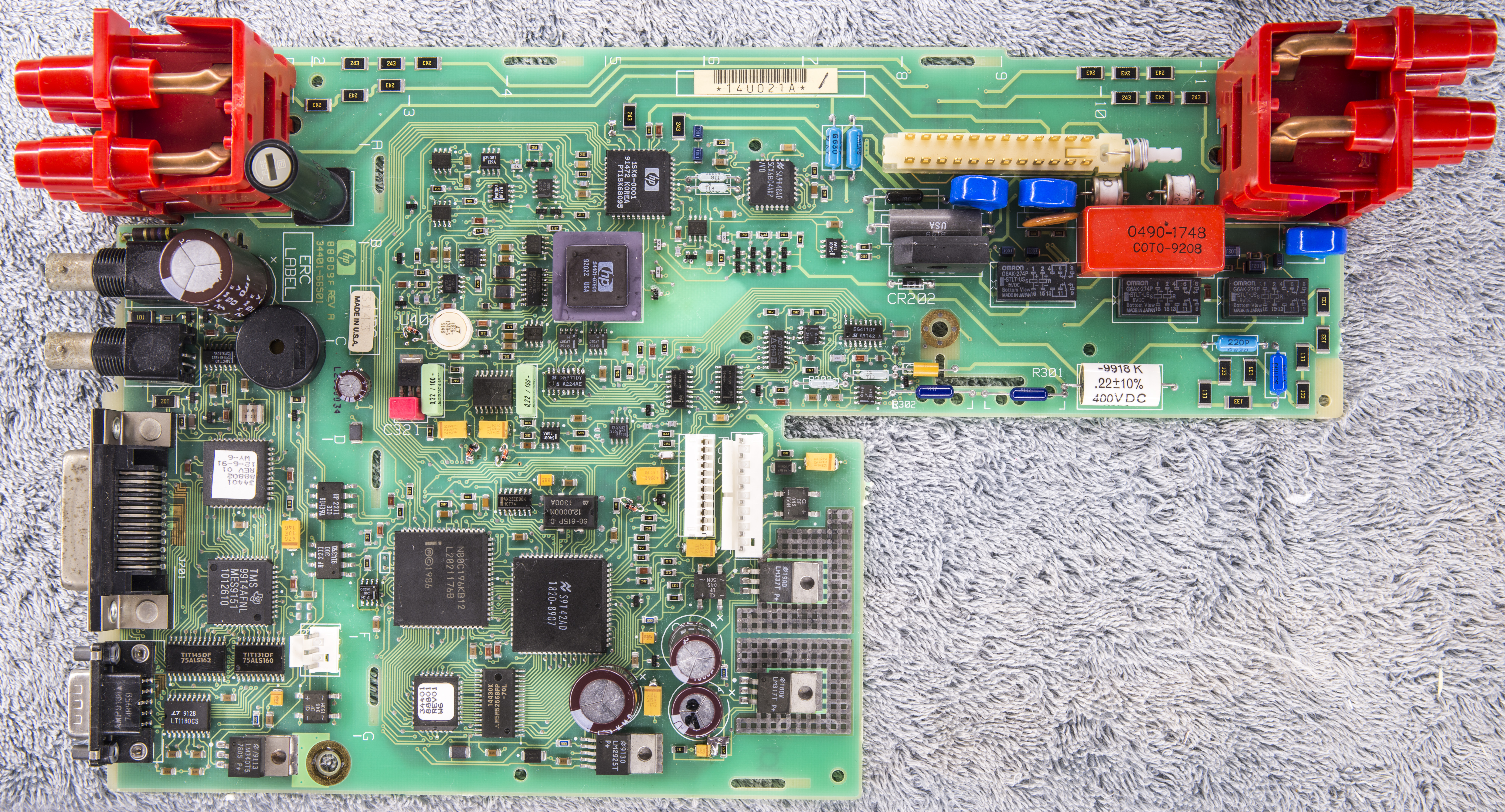
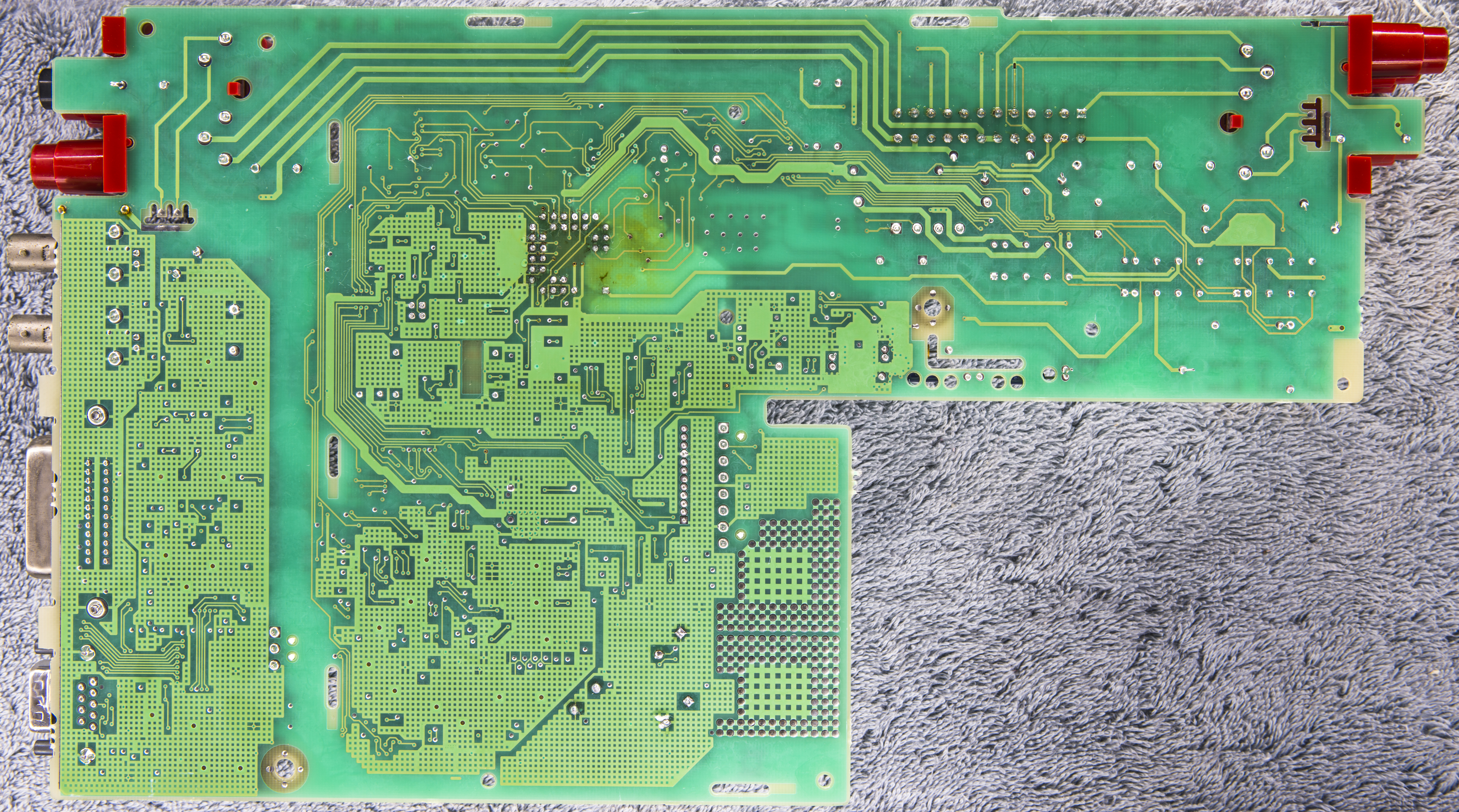
Image 7,8: HP 34401A mainboard, top and bottom side photographs.
All the magic and active parts are located on single mainboard. Banana input terminal jacks are custom-made parts, with big solid copper tube sockets bent and soldered directly to motherboard. This is one of best connections, and look really clean.
Input signals goes into front/rear input multipole mechanical switch. These are often a problem on old instruments, if contacts got contamination and unable to maintain low resistance connections. Not this time though, no problems detected with a switch, probed input 1.0000V, 10.0000V test voltages are perfectly stable after switch.
Voltage reference IC is good, verified by decades, LM399 with custom HP marking. Measured it’s output, making sure of correct 6.98VDC voltage presence. LM399 is socketed, just like more recent 3446xA instruments. Some of hobbyists were even upgrading reference to LTZ1000 circuit for better 34401A stability.
As usual, every repair should start from local power supply diagnostics and debug.
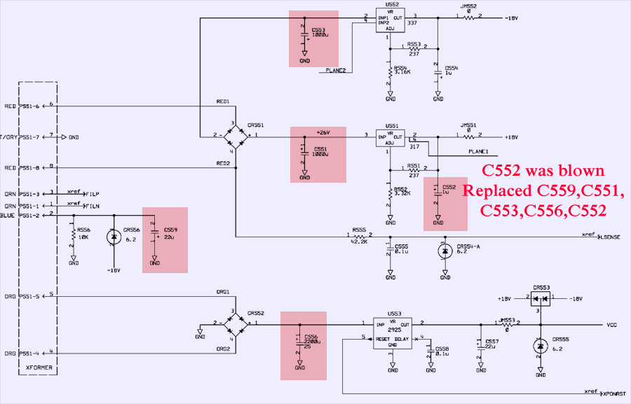
Schematics 1: HP 34401A power supplies.
Careful look revealed blown C552 tantalum 1µF capacitor on +18VDC rail. Removed remnants, cleaned and repaired PCB using copper foil and installed fresh capacitor of same size and spec.
Based on date codes on IC’s, this 34401A manufactured in 1992, and already 20 year old. This means all electrolytic capacitors must be replaced, no questions asked. Simple task which takes only 10 minutes and 2 × 1000uF 50V + 2200uF 35V +105°C C551,C553,C556 capacitors. I had some left from other repairs, so you can see already new caps on photo above.
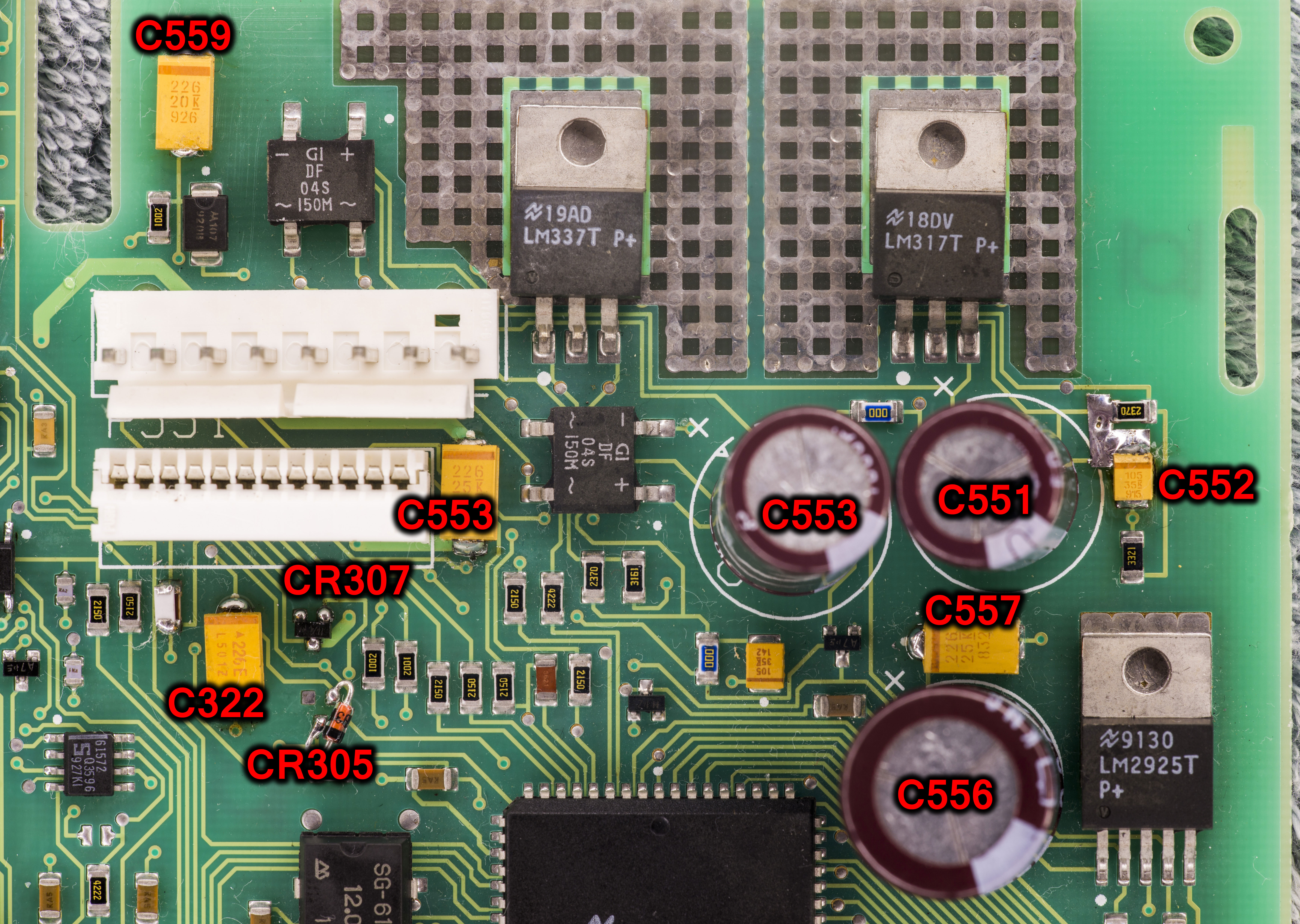
Image 9: HP 34401A PSU with replaced capacitors.
Now thinking about possible cause and overvoltage on this rail, I checked 3.3V zener diodes, which used to provide local ±15V supplies to opamps and analog circuits. And yes, some were dead short, and some were missing, likely due previous owner repair attempts.
Installed missing and replaced broken zeners CR304,CR305,CR306,CR307,CR402 with new diodes. I did not have SOT23-3 packaged type, so used leaded ones instead. No function impact anyway.
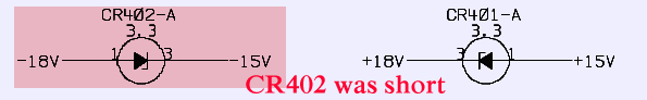
Schematics 2: HP 34401A local 15V zener regulator.
Further testing on voltage rails shown absence of -15A voltage (reading was ~0.6-1.3 VDC) and +5A voltage after resistor R310 was too low (~4.3VDC). Cause for this was again bad tantalum capacitors, C311, C312, C322, C323. These caps had resistance just about kiloohm to ground, causing excessive current flow (~15mADC) on low-power zener regulated nets. Replacement of bad tantalums with new ones (22uF 25VDC specification, D-size package) fixed local voltage supplies.
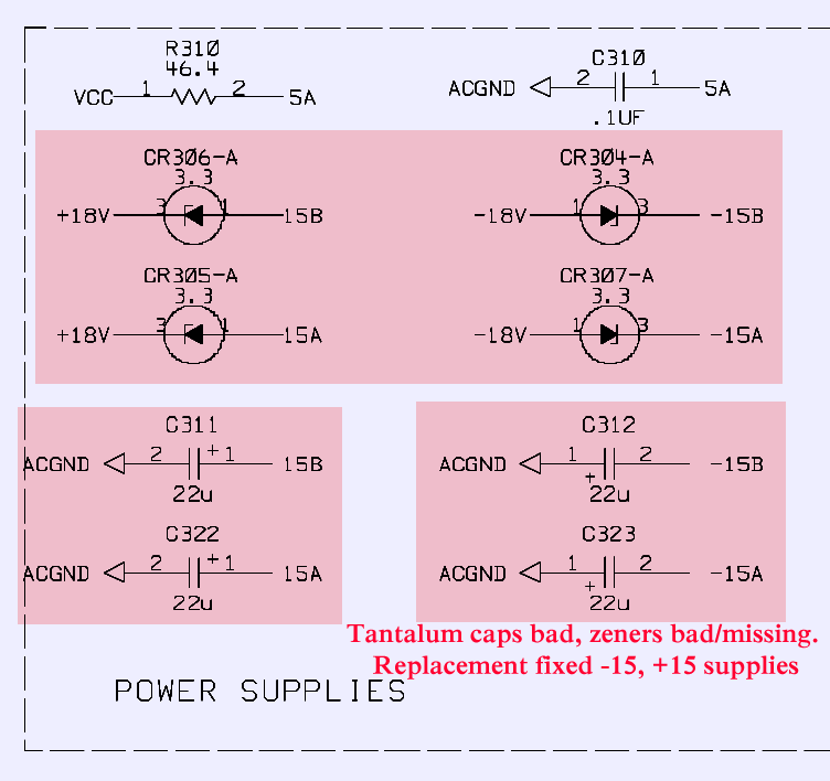
Schematics 3: HP 34401A more zener regulators and capacitors.
Now all voltages are fine, but meter still not working, with exactly same test results, wrong DCV readings and failure on any other function.
There were some cases of input protection resistors in 2512 size failure on 34401A, but check revealed no problem with input circuitry as well. Overall signal path is rather simple to read on board, even without reference to service manual or schematics. Layout is tidy and nicely done for this instrument, thumbs up to HP engineers.
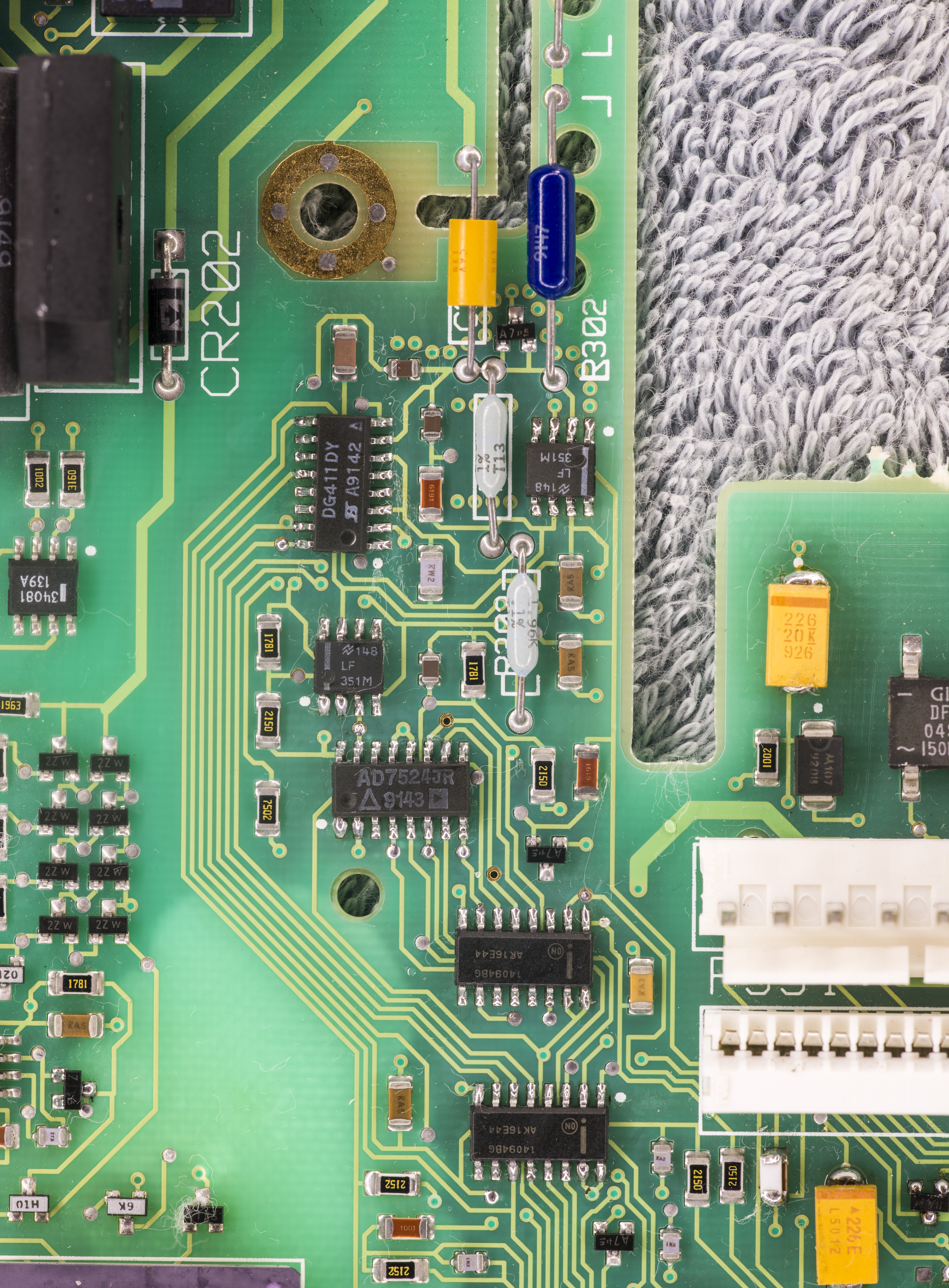
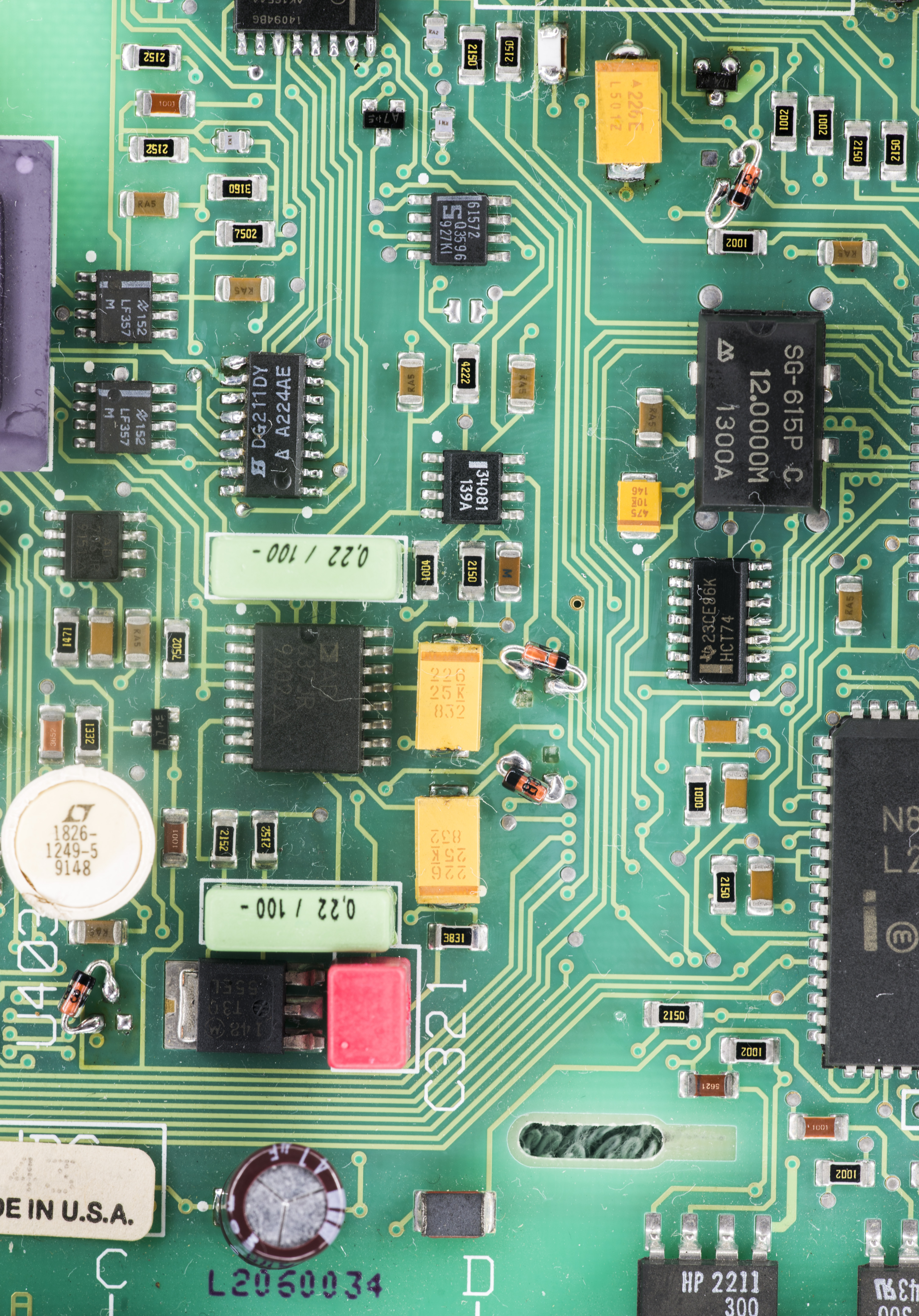
Image 10,11: HP 34401A AC circuitry and RMS converter.
Next step would be testing input front end, by tracing input signal and making sure it’s getting nice and stable right to A/D input, after all multiplexing, attenuation and gain circuitry. There is a caveat, as 34401A by default working with auto-zero enabled, so A/D input is switched between input and zero with sample rate frequency. To disable auto-zero, enter MEAS menu and select FAST 5 DIGIT resolution mode. Now we can test A/D input, with easy probing location at U106 pin 6 output opamp.
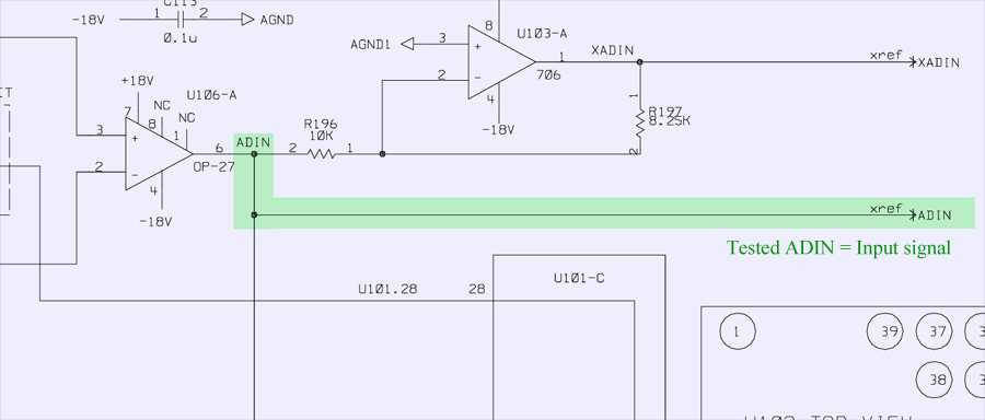
Schematics 4: HP 34401A A/D converter input test.
And test result here is good, input signal voltage is precisely match A/D input, clean and stable. Switching to different gains and DCV ranges had input adjusted properly. This results conclusion that input circuitry and front-end is OK, and bring our attention to A/D itself.
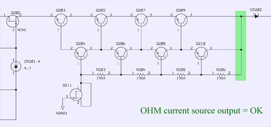
Schematics 5: HP 34401A current source for resistance function test.
I checked resistance function current source as well, by measuring current to LO ground from CR202 anode with external DMM. All currents were stable and spot on expected values. No issues here.
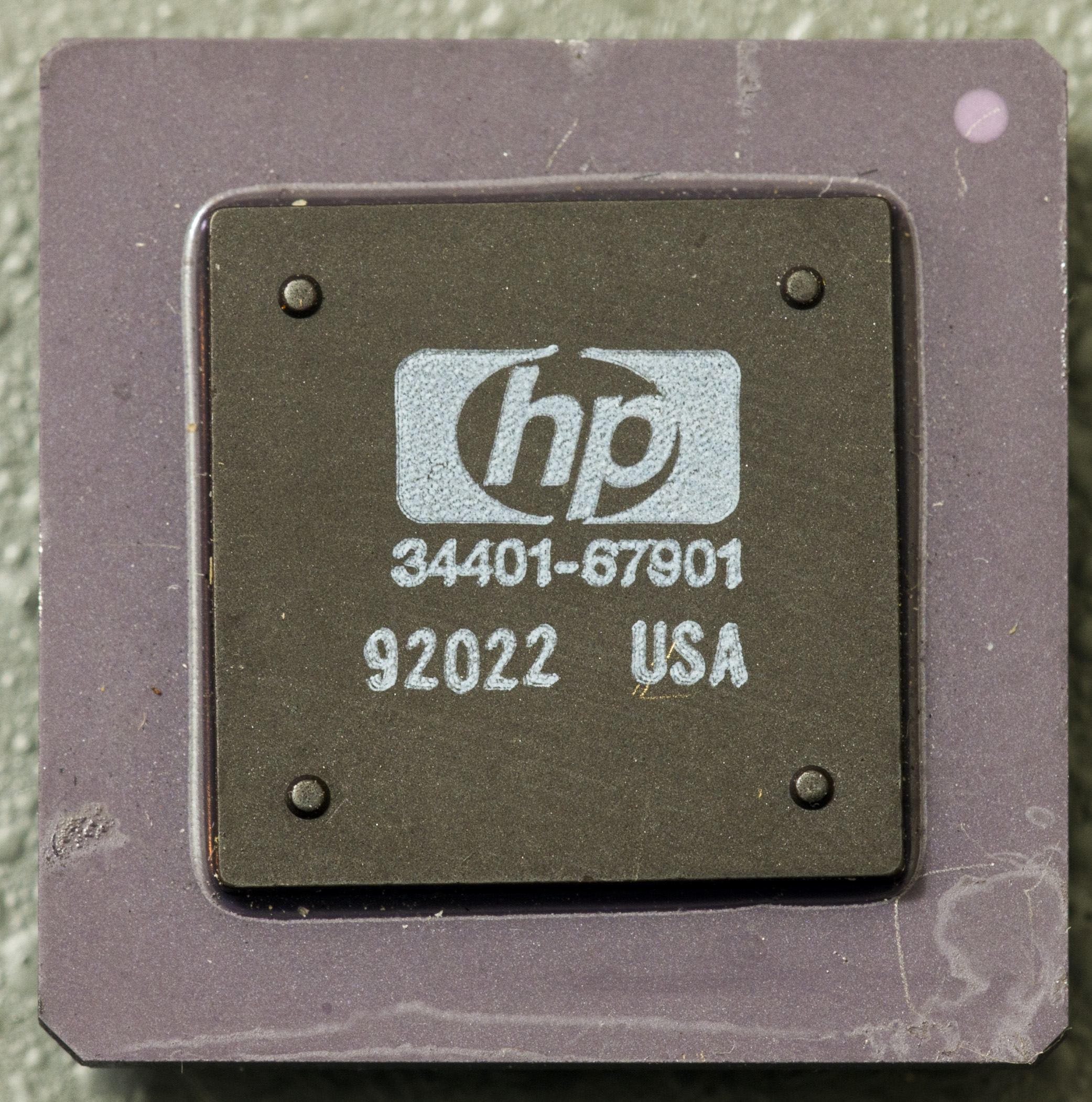
Now let’s take a closer look on A/D converter itself. Learnt from HP3458A repair it can be trouble to debug, so I suspected custom resistor network hybrid ASIC U102, even though initial measurements was showing that it is likely to be OK.
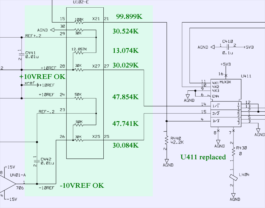
Schematics 6: HP 34401A resistor network U102 and references test.
Signals after voltage divider and reference voltage +10REF, -10REF generated off 7V from LM399 were correct, but nevertheless I desoldered U102 and measured it separately, just to be sure. As you may already guess, all resistances were fine. It’s important to have U102 resistor network ASIC removed from PCB, as other circuits onboard would make measuring not accurate.
| ASIC U102 resistor element | Specification | Measured resistance | |
| 1-12 | 9.903 MΩ | 9.9MΩ |  |
| 12-39 | 100 KΩ | 99.963 KΩ | |
| 18-19 | 2 KΩ | 2.0004 KΩ | |
| 19-17 | 2 KΩ | 2.0008 KΩ | |
| 16-19 | 2 KΩ | 2.0228 KΩ | |
| 3-7 | 500 KΩ | 505.059 KΩ | |
| 3-9 | 1 MΩ | 1.009 MΩ | |
| 3-6 | 50 KΩ | 50.387 KΩ | |
| 3-5 | 5 KΩ | 5.0539 KΩ | |
| 3-4 | 28 KΩ | 28.8125 KΩ | |
| 26-25 | 30 KΩ | 30.084 KΩ | |
| 23-26 | 50 KΩ | 47.741 KΩ | |
| 24-23 | 50 KΩ | 47.854 KΩ | |
| 28-29 | 12.857 KΩ | 13.074 KΩ | |
| 13-11 | 2 KΩ | 2.0115 KΩ | |
| 13-14 | 18.1 KΩ | 18.1422 KΩ | |
| 35-36 | 4.4 KΩ | 4.4318 KΩ | |
| 36-33 | 500 KΩ | 493.95 KΩ | |
| 28-27 | 30 KΩ | 30.029 KΩ | |
| 30-29 | 30 KΩ | 30.524 KΩ | |
| 37-38 | 4.4 KΩ | 4.4590 KΩ | |
| 38-31 | 500 Ω | 496.72 Ω |
Table 1: U102 ASIC resistor network measurement results
U411 multiplexer 74HC4053 was replaced as well, but issue was same. There are two things left to test, U101 switching ASIC and control logic. Since input and gain switches inside U101 HP 15K6-0001 were operating correctly, I traced control to A/D from digital side, and quickly found that integrating switch U411 is controlled by 74HC74 Dual DFF.
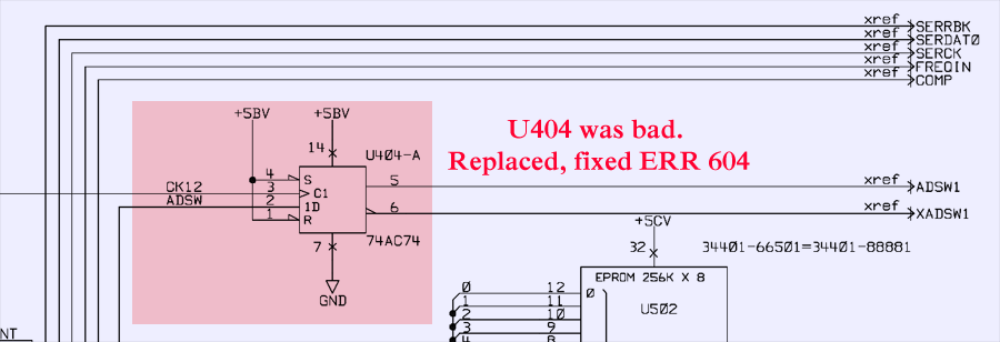
Schematics 7: HP 34401A bad DFF part, which caused failure on A/D integrator.
Since it’s very cheap and popular component, I did not bother checking it and just replaced with new IC.
Tada….reading correct voltage now!
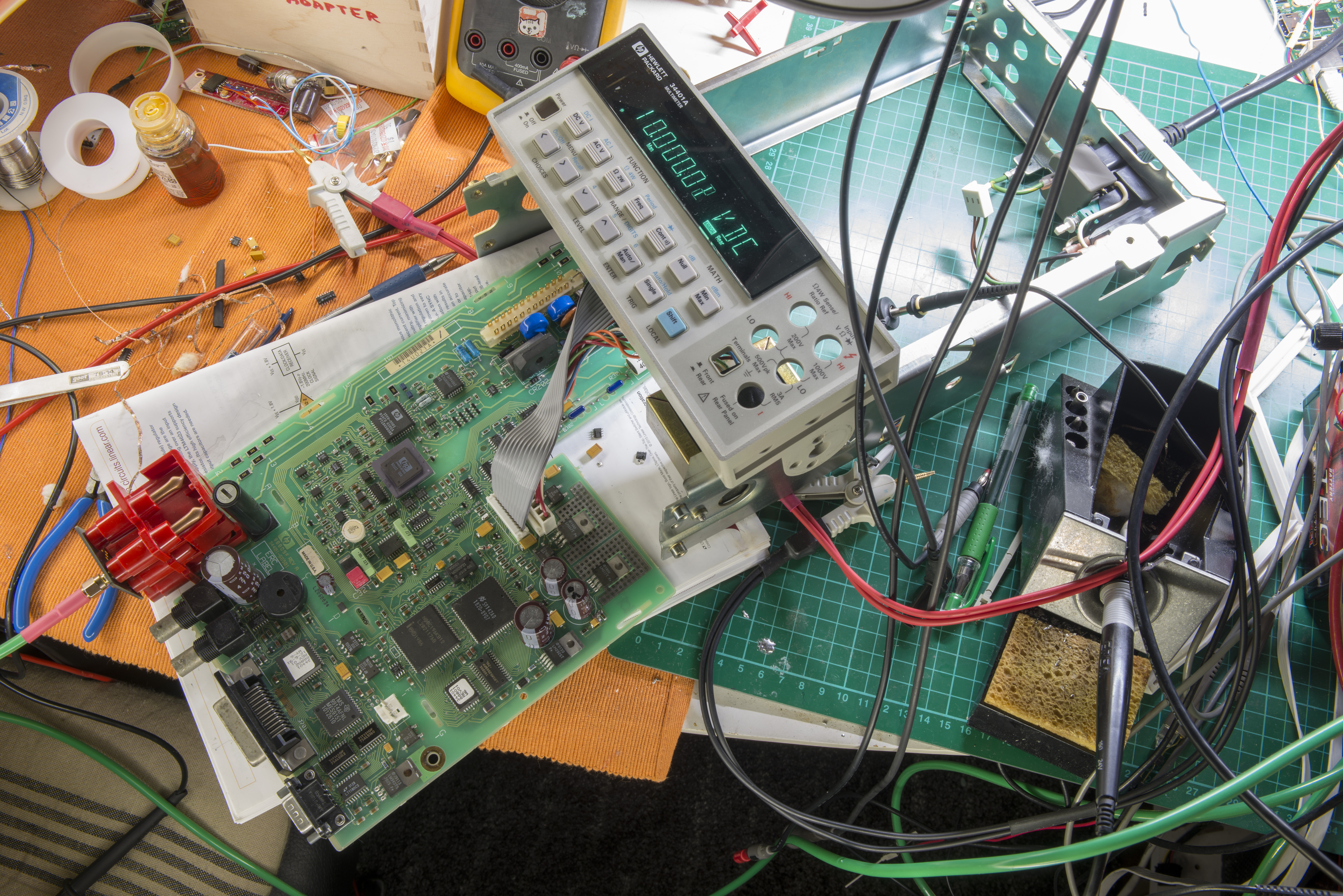
Image 12: HP 34401A DMM is reading voltage.
Since board does not have RefDes markings around parts, I did highlights on photo to summarize on changed parts during debug and test:
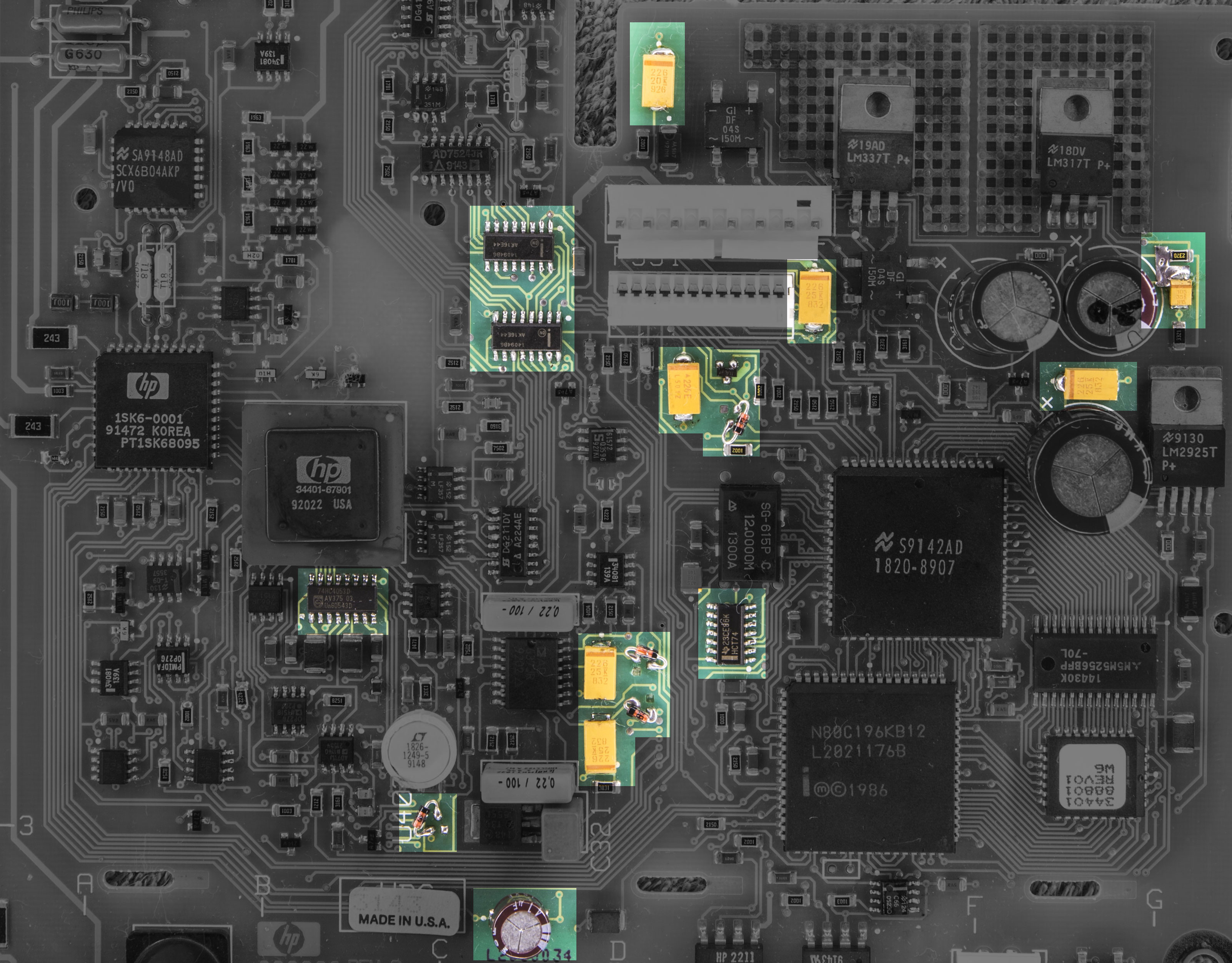
Image 13: HP 34401A Replaced components locations.
Shift registers 4094 on AC circuitry and few other opamps were replaced as well, but that was actually unnecessary.
Firmware
U502 PLCC ROM chips are soldered down on PCB, as since meter is not mine, I did not bothered to remove them and read, sorry.
| Firmware | HPAK P/N | Binary | Checksum |
|---|---|---|---|
| 34401A Firmware Rev.10 | 34401-88891 | ZIP-file | 01B9AE43 |
Calibration ROM contents from 93C66 SO8 was dumped in this binary
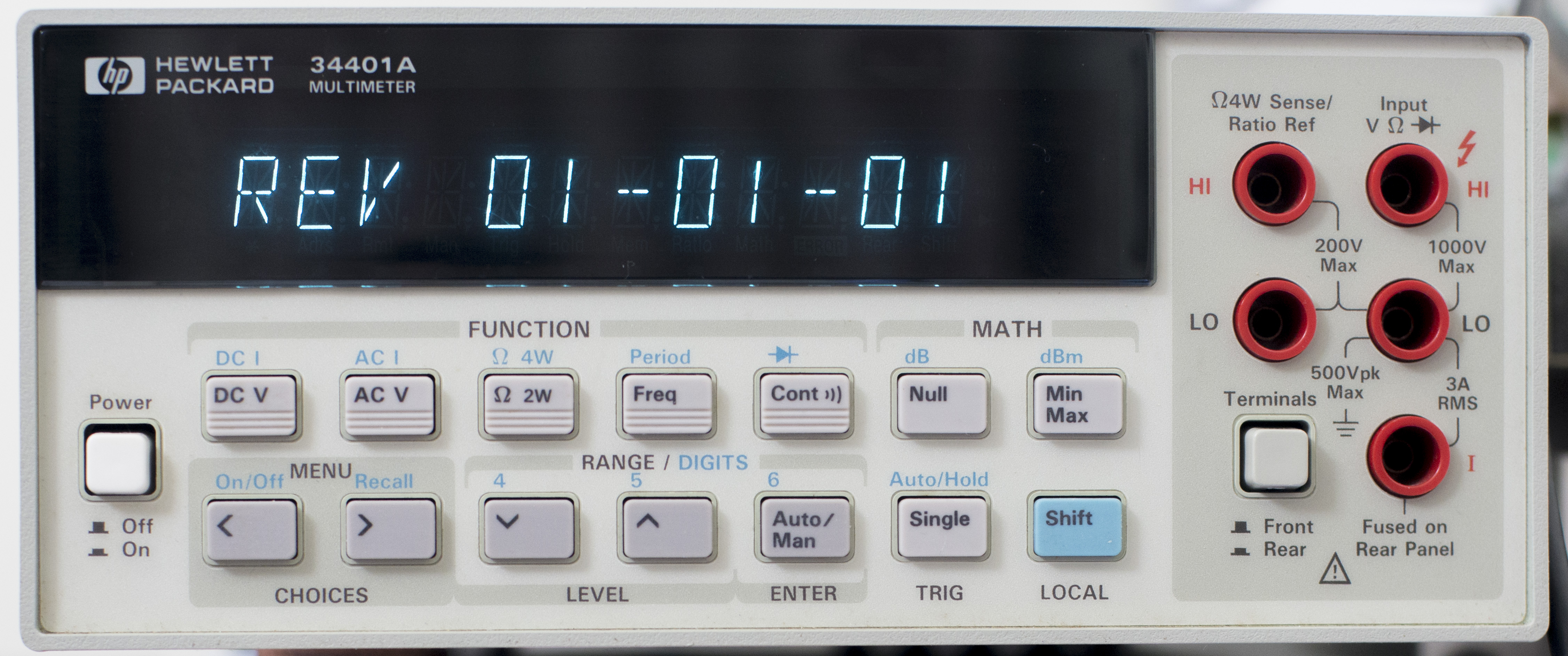
Image 14: HP 34401A Firmware revision 1.
Calibration January 17, 2016
After repair, it’s important to have proper calibration, as it’s the only way to ensure meter is providing correct readings on input signals. To do so I will use number of DCV and DCI sources, as well as set of fixed precision resistors. All this signals are measured by reference meter, to get actual value, and then transferred to 34401A under calibration, by switching probes and entering measured value as reference point. After calibration, values are compared to Keithley meter to ensure they agree on readings.
Calibration was referenced to measurement results of my Keithley 2001 (which was calibrated in February 2014 by Tektronix, and is most accurate meter I currently have up to date)
Few photos of calibration steps for better understanding. First step – zero calibration with 4W short
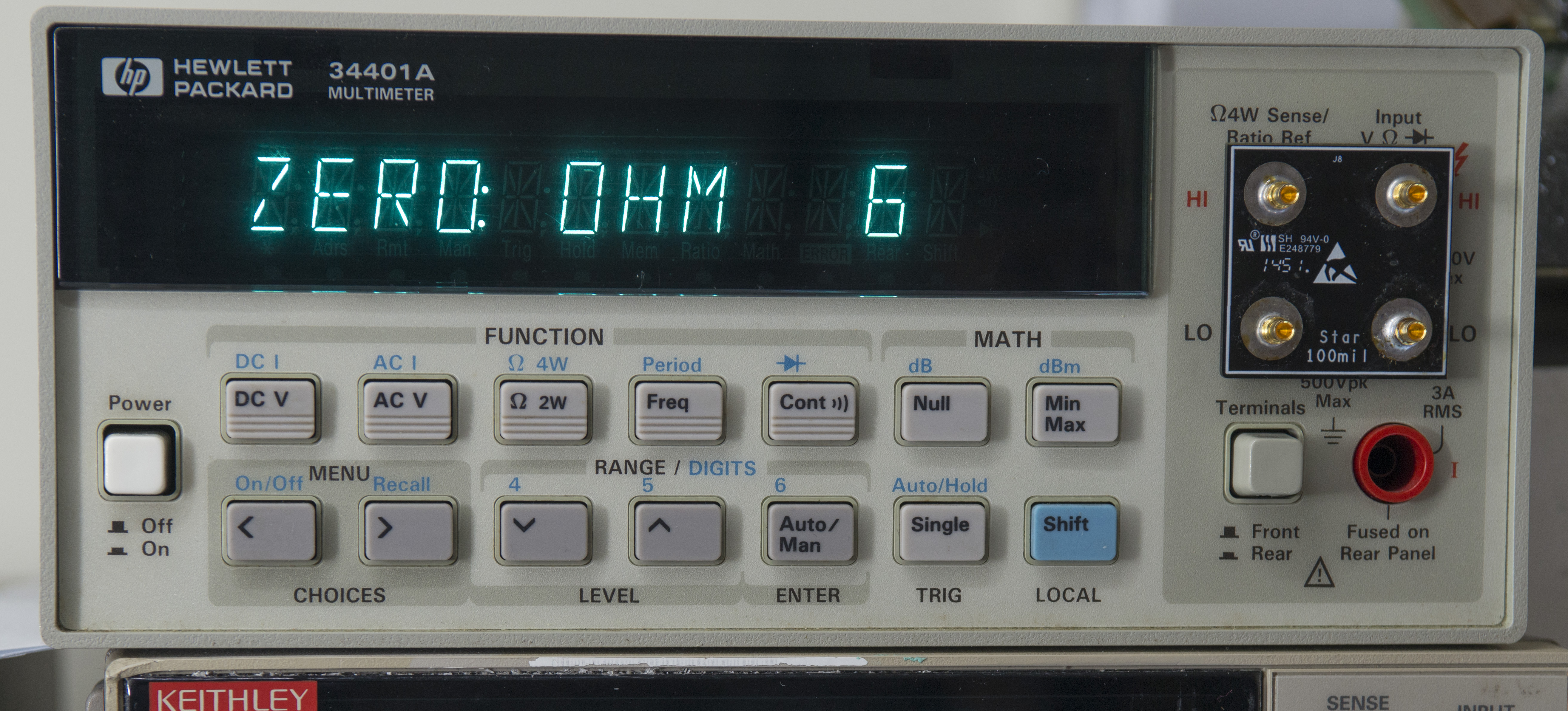
Image 15: HP 34401A Zero calibration with 4W short.
DCV calibration, 100mV, 1V, 10V.
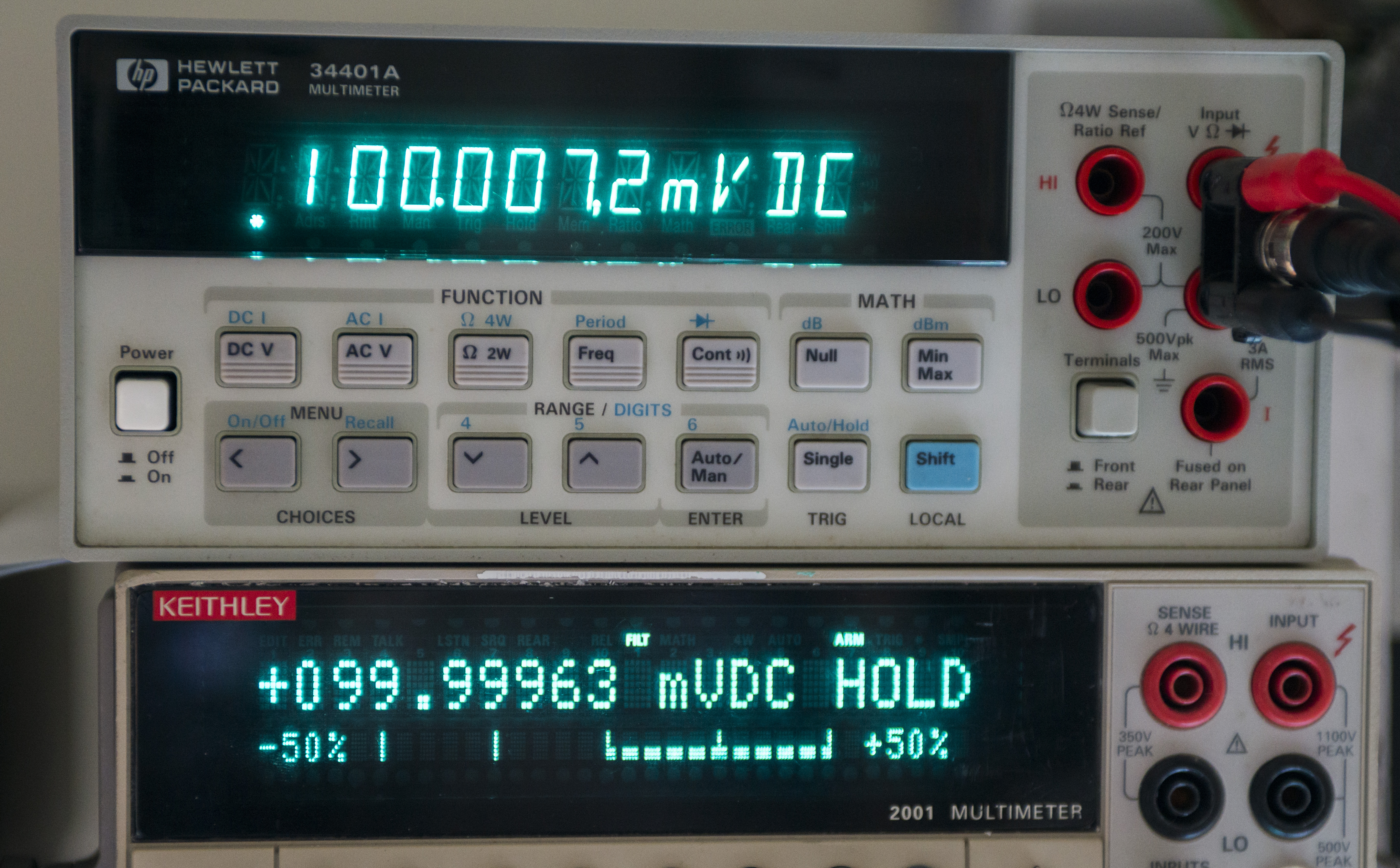

Image 16,17: HP 34401A DCV calibration with 100mVDC, 10VDC.
Higher voltages calibration. I used HP 3245 with x10 option 001 as 100VDC source, and Ultravolt DC-DC as 1000VDC source for this task:
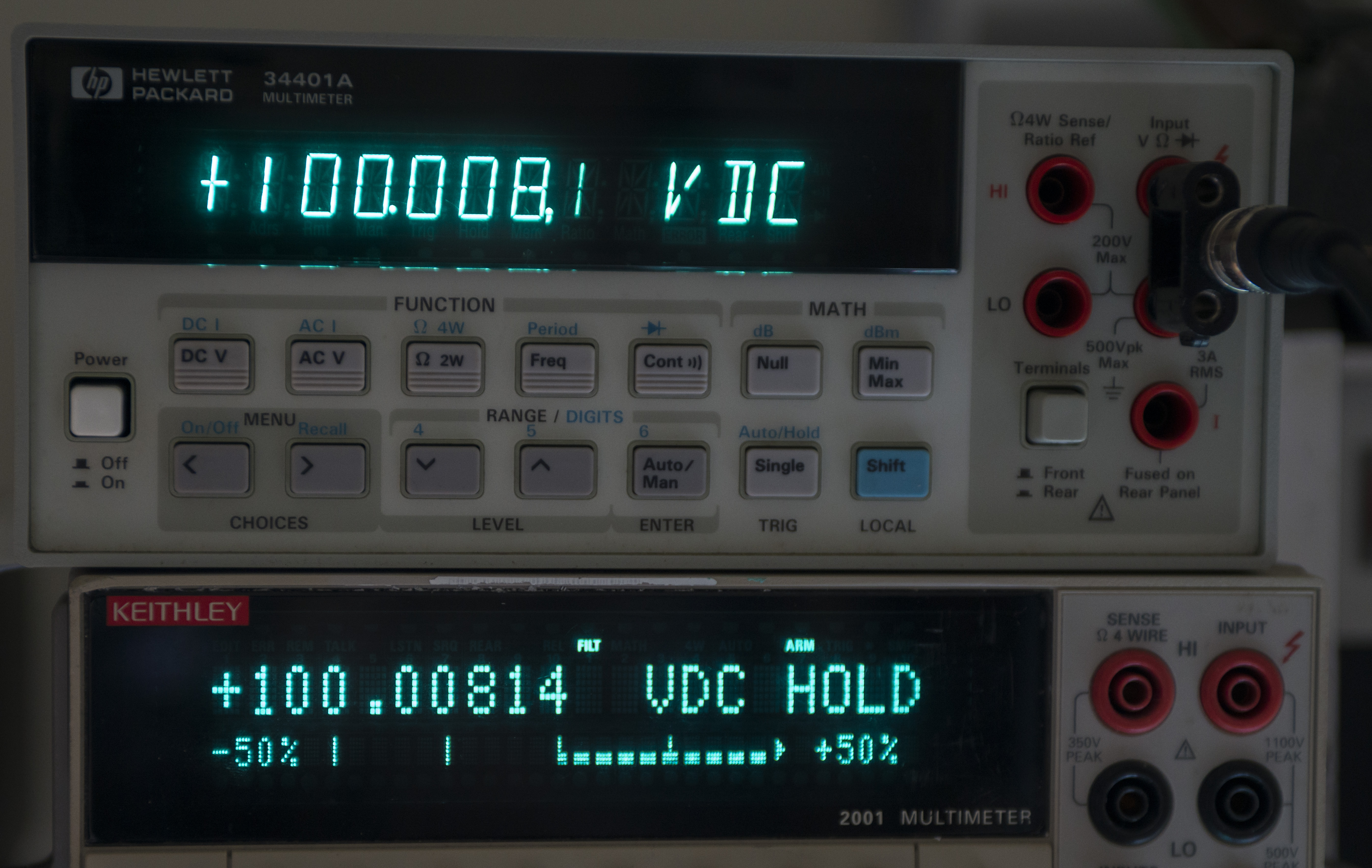
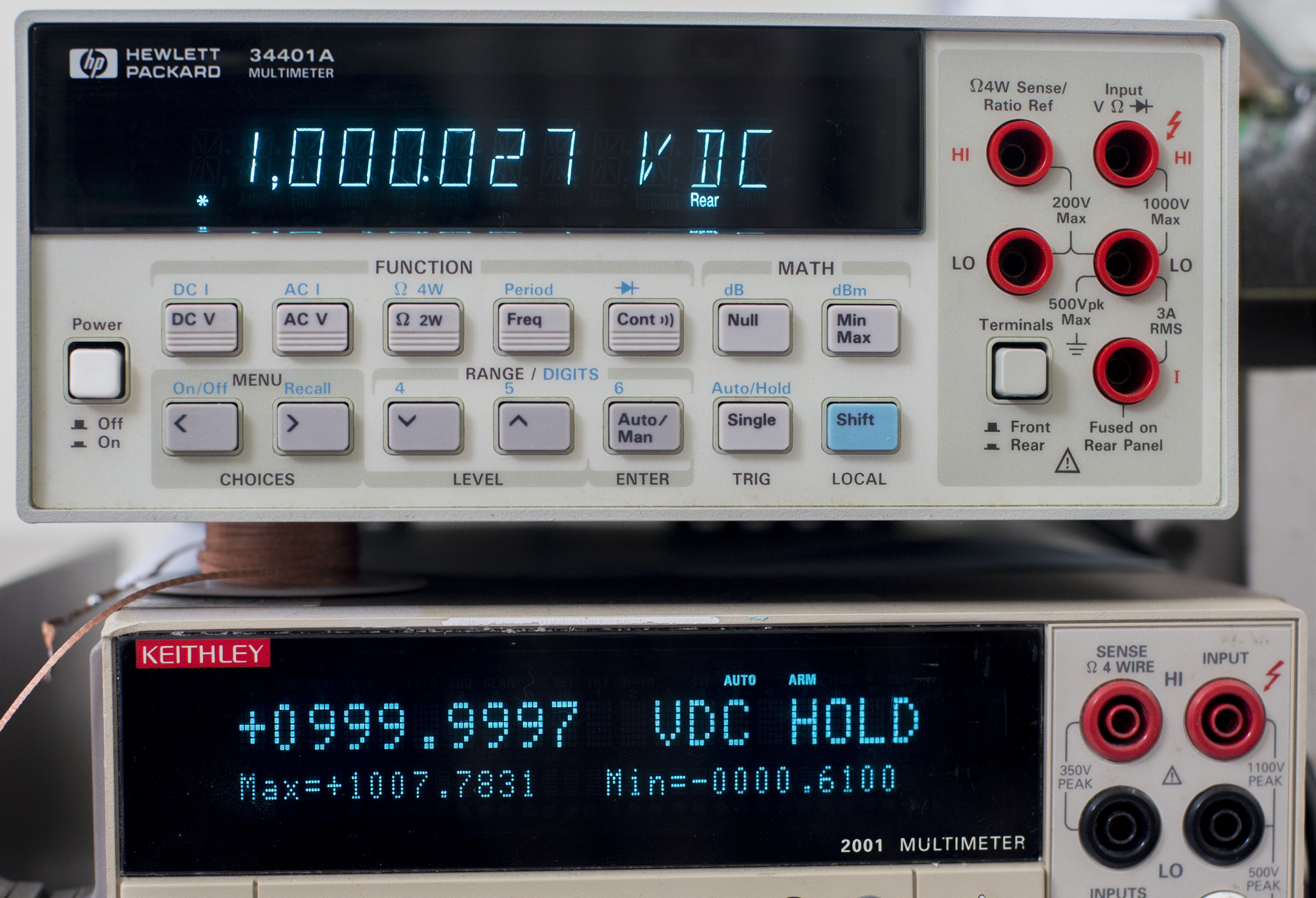
Image 18,19: HP 34401A DCV calibration with 100VDC, 1KVDC.
Vishay BMF resistors and ESI DB52 decade resistor were used to calibrate resistance 4W mode:

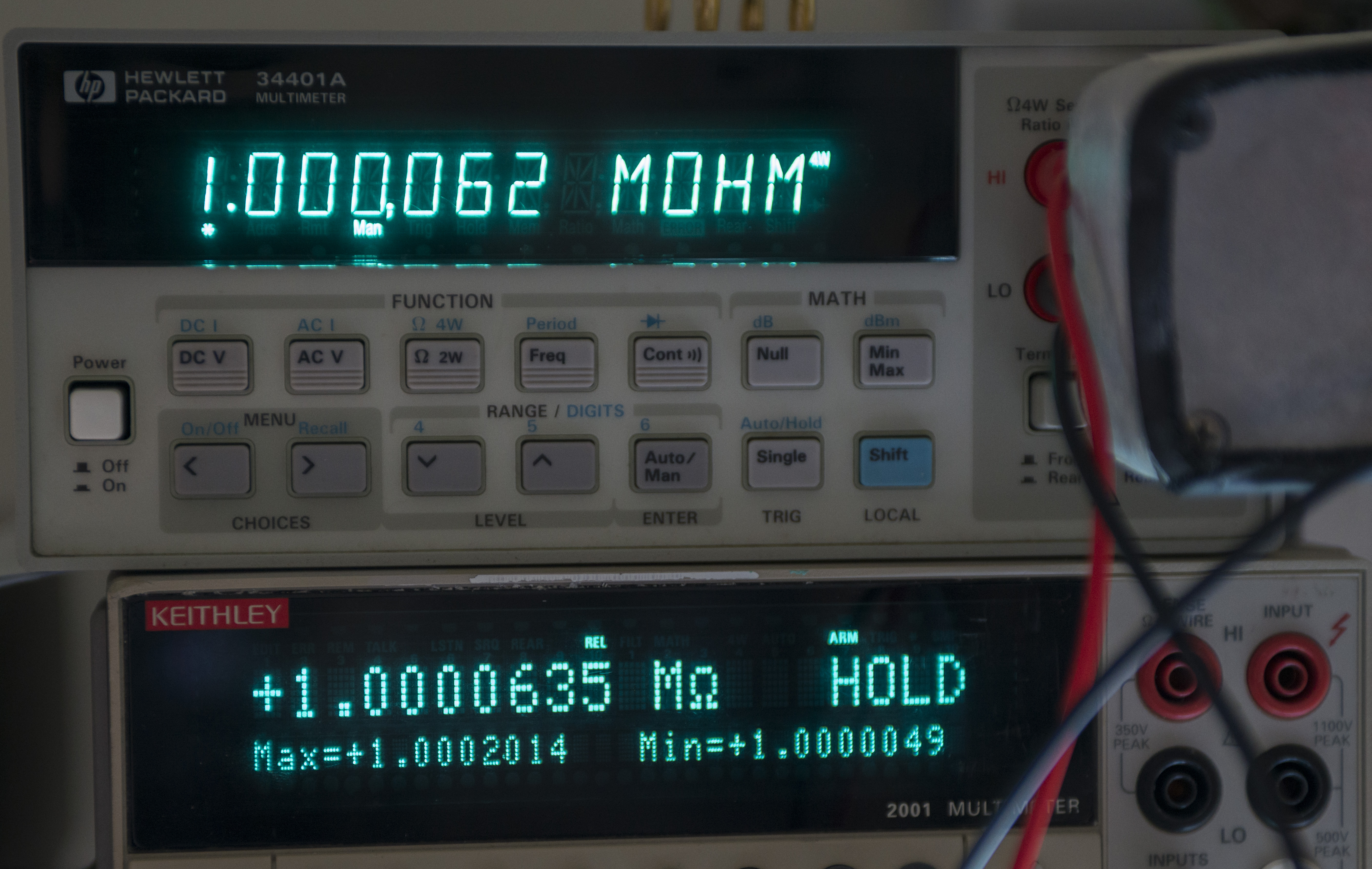
Image 20,21: HP 34401A 4W resistance calibration with 10KΩ and 1MΩ resistors.
Final test with 10VDC:
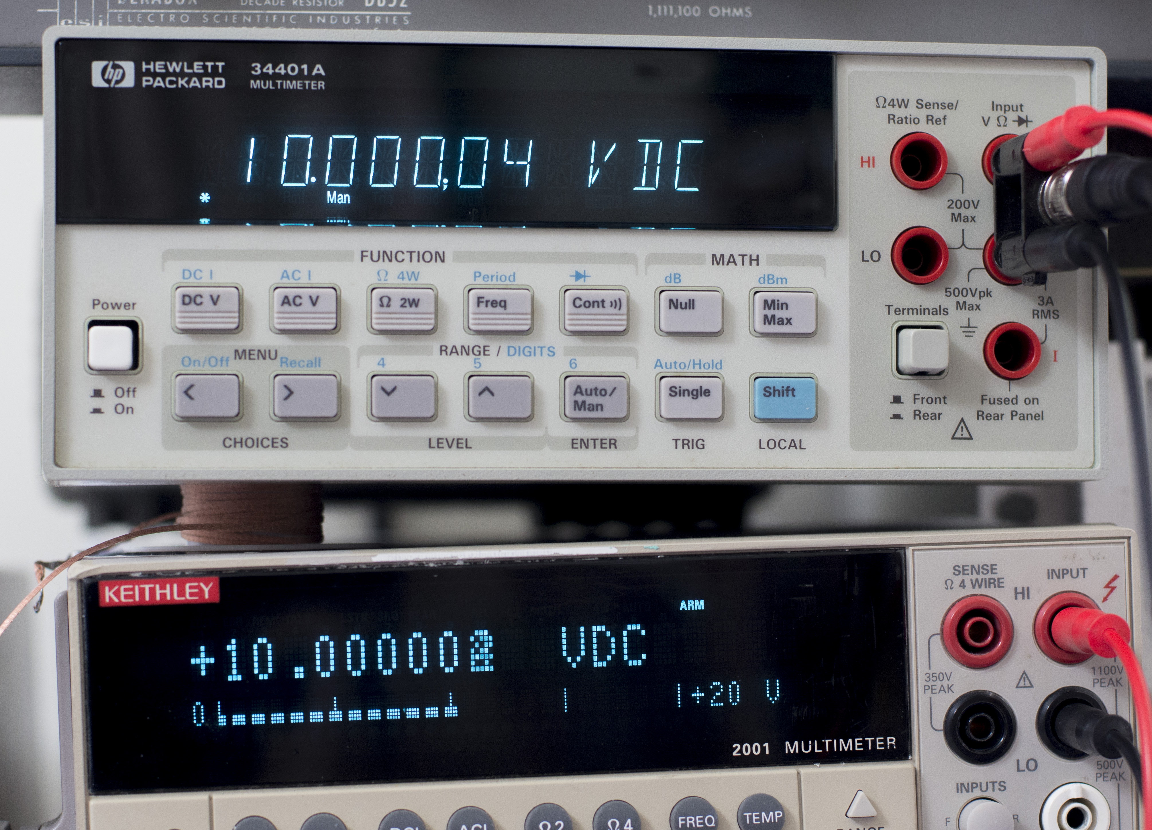
Image 22: HP 34401A Final test with 10VDC.
Short video covering calibration and testing for HP 34401 using standards available:
Calibration February 10, 2019
Almost exactly 3 years or 1120 days since previous calibration we got this meter back for the quick verification test. xDevs.com lab capability and accuracy enhanced a lot over this period. This enabled much better TUR for benchtop meter verification, like this 6½-digit HP 34401A.
DUT meter was left to warm up for few hours to stabilize before actual tests were performed. Calibration points selected in according with Agilent 34401A Service manual. Freshly calibrated Fluke 5720A/HLK calibrator boosted with Fluke 5725A amplifier used to execute full adjustment and calibration of the 34401A.
Automated procedure in python linux-gpib application was used to perform verification and data collection of all key multimeter functions.

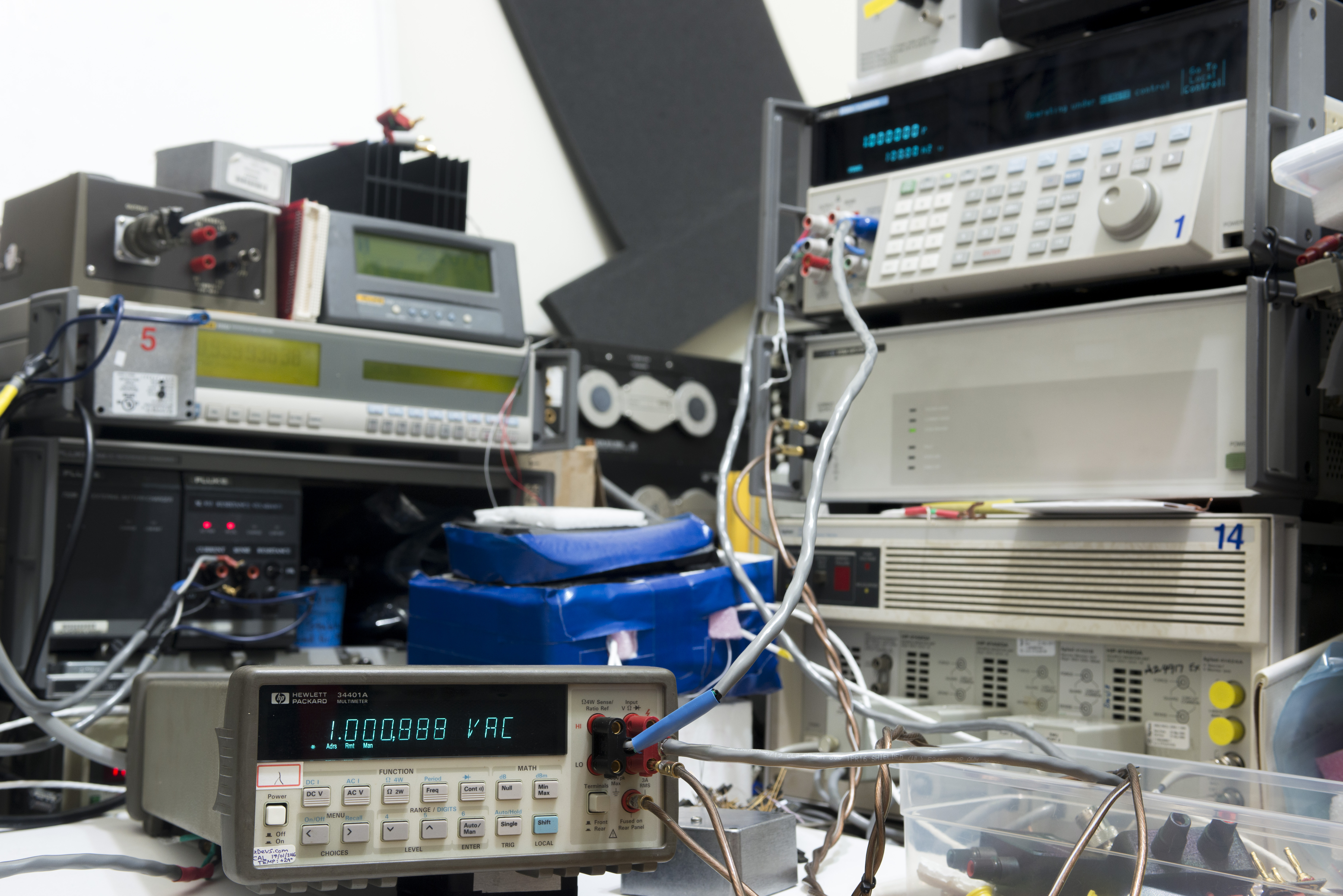
Image 23,24: HP 34401A calibration setup at xDevs.com, 2019 version
This test however is NOT traceable calibration report and cannot be used as such for any legal purposes, it is mere indicator of equipment agreement, using these particular samples. Do not assume that measurement is correct just because meter and source are in agreement, account for uncertainty and all possible error sources. Refer to A Beginner’s Guide to Uncertainty of Measurement from NPL for better introduction on these aspects.
For each test equipment was interconnected using low-thermal cables. Calibrator was artifact-calibrated to Fluke SL935 and 792× 10V reference.
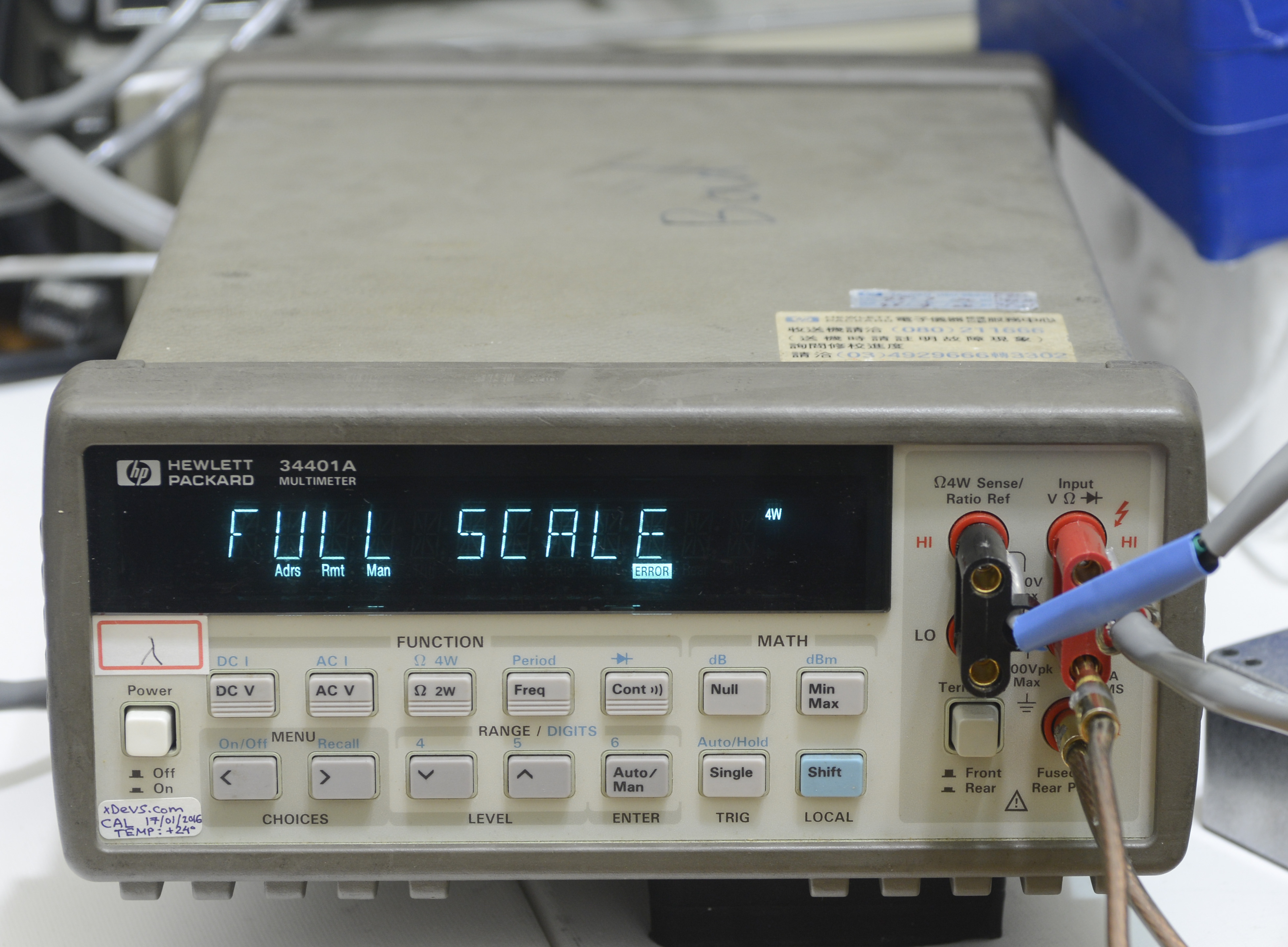
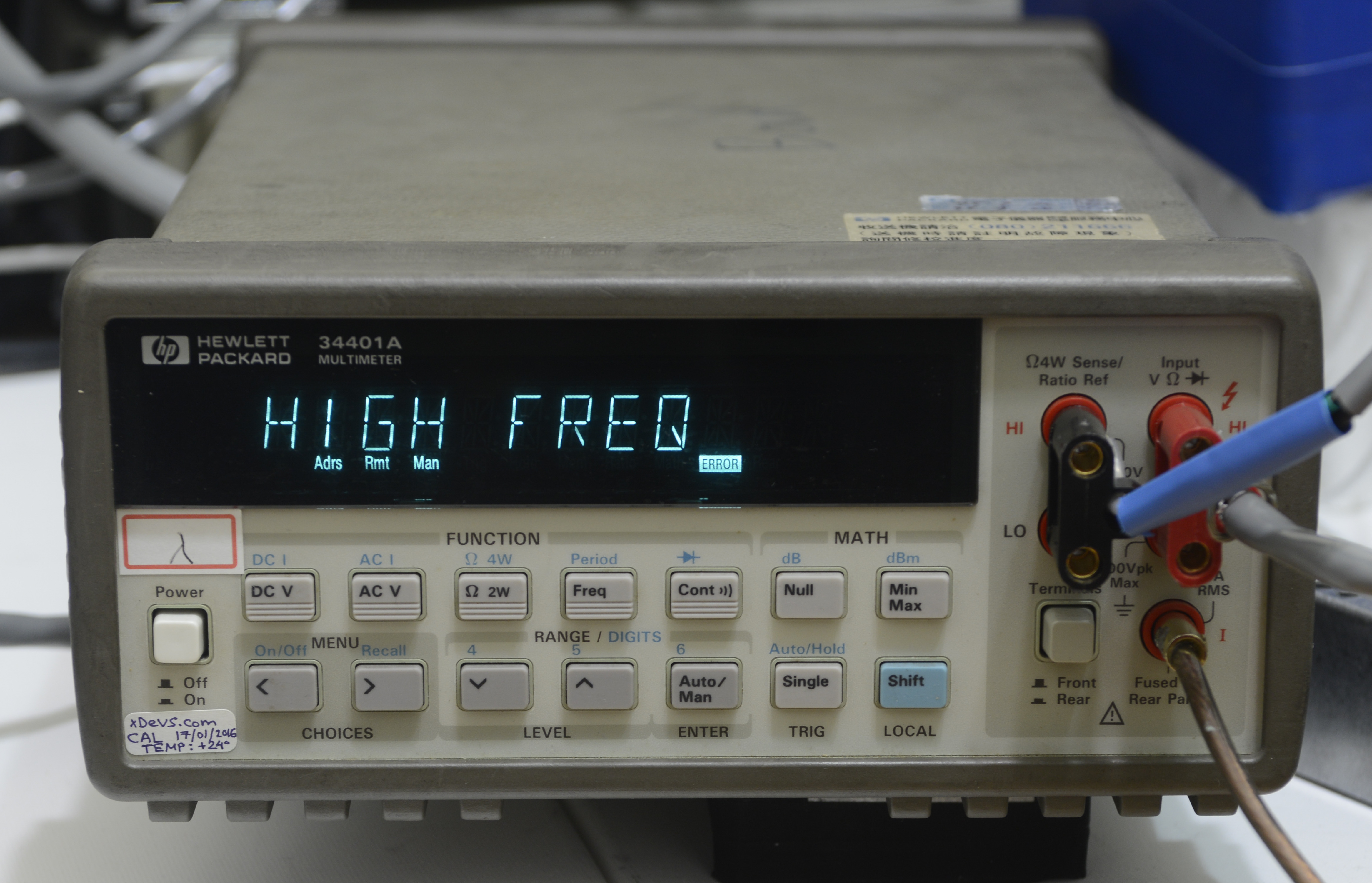
Image 25,26: HP 34401A calibration steps during adjustment
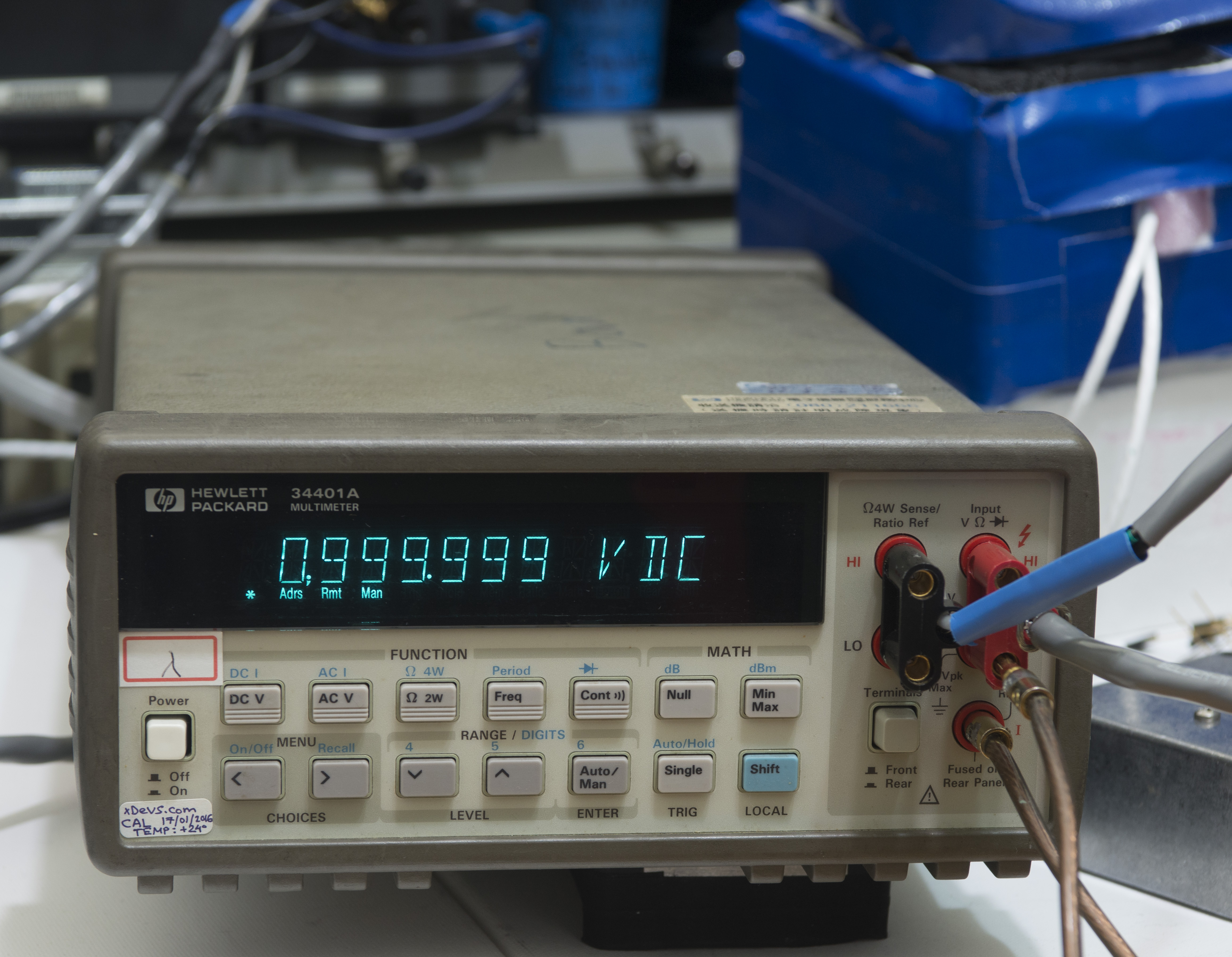
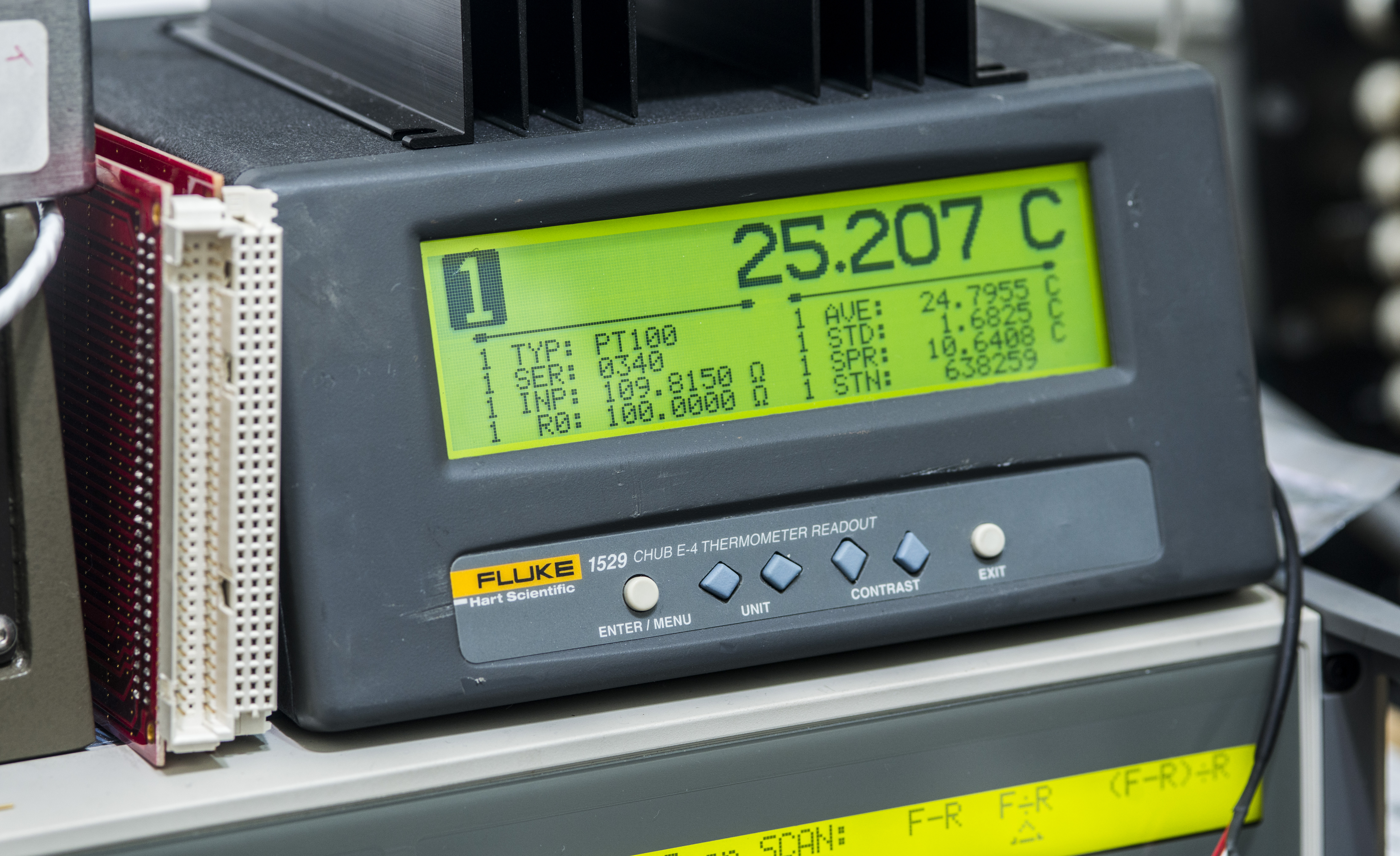
Image 27,28: HP 34401A 1VDC check and ambient temperature monitoring with Fluke 1529 and RTD
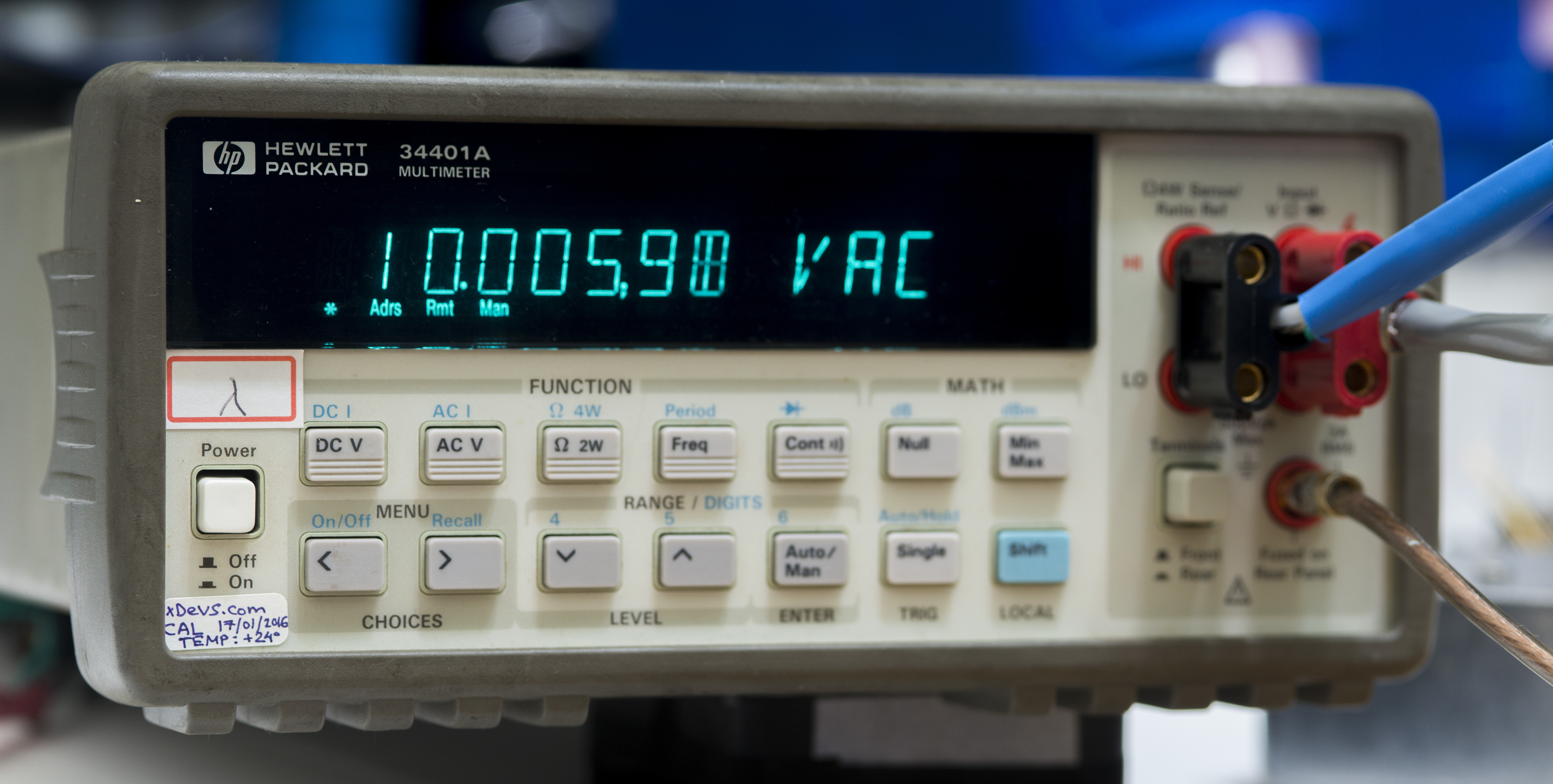
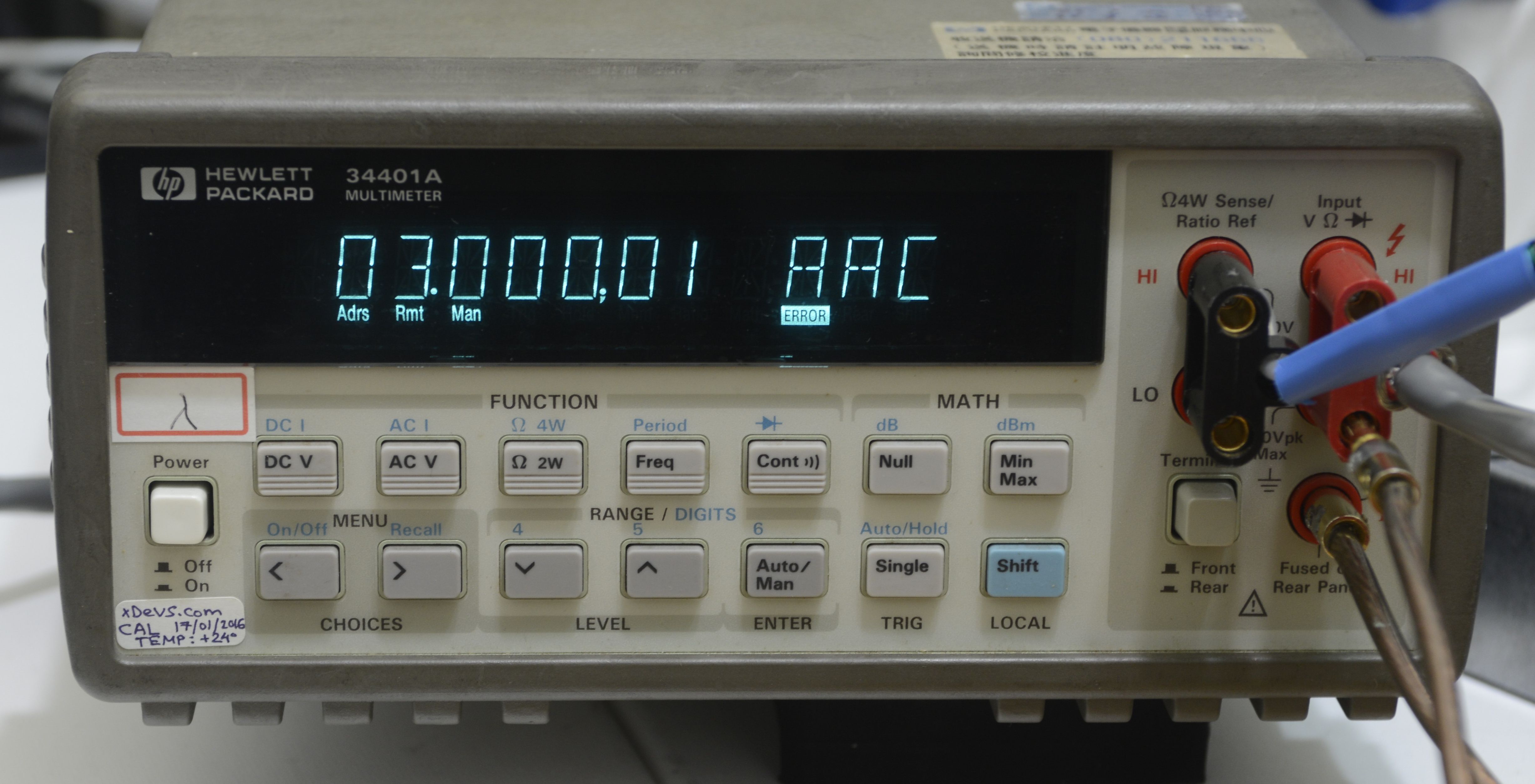
Image 29,30: 10VAC 50kHz and 3 AAC 1kHz measurement points
Linearity verification on base 10VDC range, using first Keysight 3458A and second Keysight 3458A as reference:
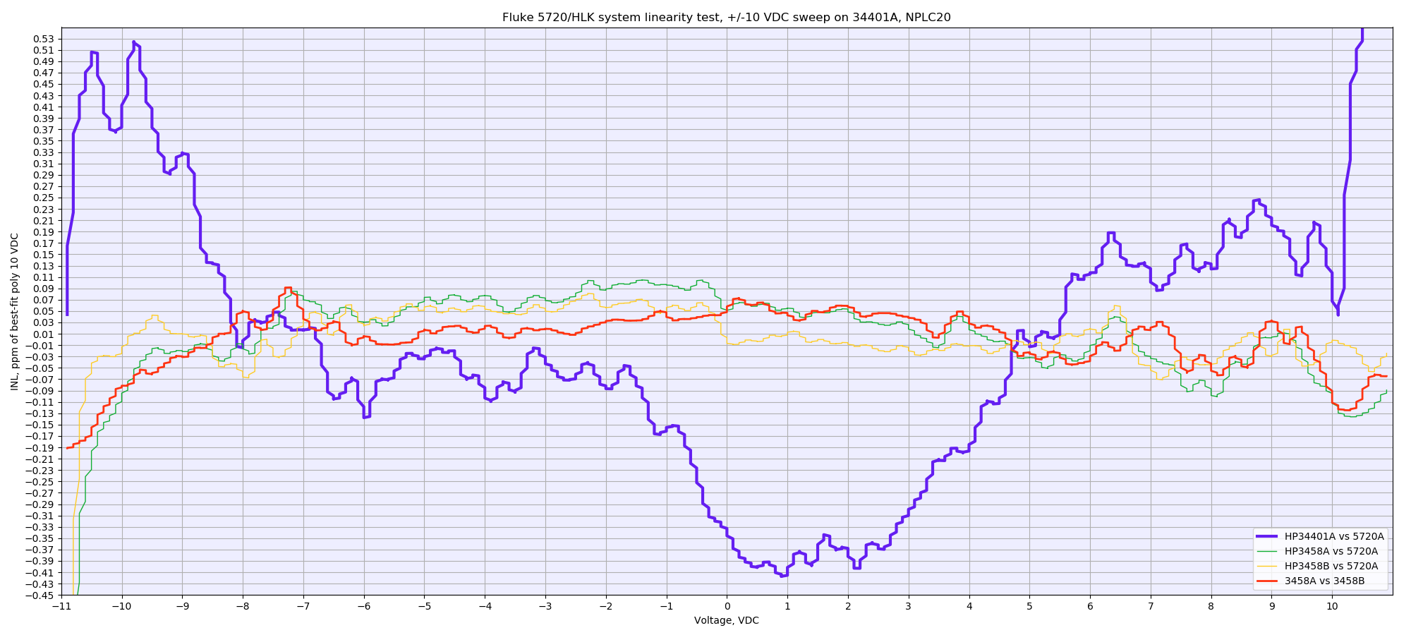
Image 31: HP 34401A DC voltage linearity verification on 10V range
No problems with ADC linearity were detected, meter well within manufacturer’s 2 ppm of measurement + 1 ppm of the range specification.
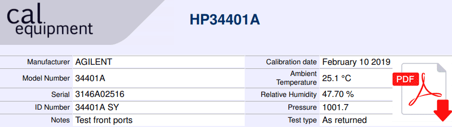
Generated calibration report, condition as received. Check only DCV and 4W resistance functions:
HP 34401A calibration test, February 10, 2019. As received DCV/4W resistance.
And as returned back to owner, with report covering all major functions:
HP 34401A calibration test after adjustment, February 10, 2019.
These reports cover 24 hour specification limits, not 1 year.
Restoration summary
| Item | Cost | Shipping | Supplier |
| Dead HP 34401A saved from dumpster | 10$ | None | Local dumpster |
| 5pcs 3.3V zeners | 2$ | Free | DigiKey |
| Capacitors | 5$ | Free | DigiKey |
| 74HC74 SOIC | 0.5$ | Free | Digikey |
| 74HC4053 MUX SOIC | 0.5$ | Free | Digikey |
Table 2: Time worklog summary
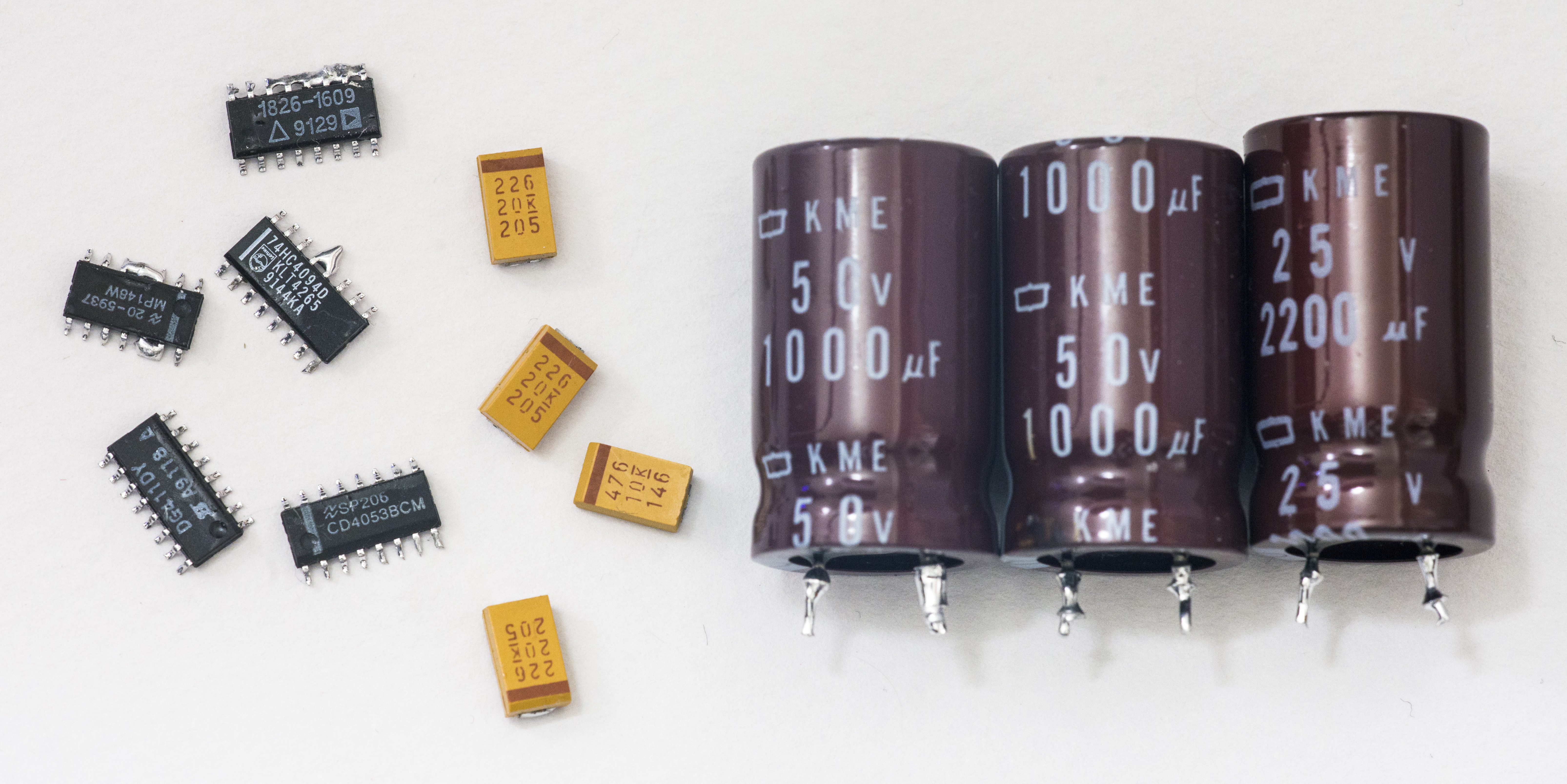
Image 32: Bad parts from meter.
Total man-hours spent on this project around 20 hours, give or take few. As meter cost, and end result, I’m satisfied with outcome and time spent on this repair. Especially considering, that I never had 34401A before.
Equipment used during restoration project:
- Fluke 5720A/HLK Calibrator with 5725A Amplifier (calibration 02/2019)
- Keysight 3458A (calibration 02/2019) as reference DMM and linearity standard
- Keithley 2001 DMM (calibration 02/2014) as calibration transfer standard
- Keithley 2400 SMU (calibration 05/2015) as current calibration source
- Soldering gear, ERSA I-CON station
- MiniPro TL866CS programmer to read/write ROMs/RAMs
- Ultravolt 1A12-P4-F-M adjustable DC-DC module as 1000V calibration source
- HP 3245A as 100V calibration source
- ±30 ppm/K EDC MV106 DC voltage standard (calibrated 02/2014 from K2001) as 100mV, 1V, 10V calibration source
- ESI DB52 resistance decade to test OHM operation
- Set of Vishay foil resistors for resistance artifact calibration
- Nikon D800 with 28-70/2.8D, Sigma 150/2.8 Macro, tripod
- 100 mL of IPA and alcohol to clean PCB
Credits to EEVBlog member sonicyang which own this meter, for making this repair article possible.
Discussion about this article and related stuff is welcome in comment section or at our own IRC chat server: irc.xdevs.com (standard port 6667, channel: #xDevs.com). Web-interface for access mirrored on this page.
Projects like this are born from passion and a desire to share how things work. Education is the foundation of a healthy society - especially important in today's volatile world. xDevs began as a personal project notepad in Kherson, Ukraine back in 2008 and has grown with support of passionate readers just like you. There are no (and never will be) any ads, sponsors or shareholders behind xDevs.com, just a commitment to inspire and help learning. If you are in a position to help others like us, please consider supporting xDevs.com’s home-country Ukraine in its defense of freedom to speak, freedom to live in peace and freedom to choose their way. You can use official site to support Ukraine – United24 or Help99. Every cent counts.
Modified: Jan. 18, 2026, 3:21 p.m.