Contents
- Intro
- Disclaimer
- Manual references
- Initial inspection and basic disassembly and service
- Firmware
- Custom FRAM adapters and EEPROM programmer adapter
- Other possible issues
- Tweaks and tricks
- Calibration
- Performance verification
- Restoration summary
Intro
We all know Keithley/Tektronix, HP/Agilent/Keysight, LeCroy and Fluke. However few decades back bit less known T&M manufacturer Datron was also famous for their high-performance DMM and calibrators lineup. Datron was acquired by Wavetek in 1987 for $15.8M US Dollars. Wavetek was still manufacturing original Datron DMMs and calibrators, and eventually sold it’s T&M division in year 2000 to Fluke for $40M. Fluke was happy to obsolete all and everything, replacing the void in the market with their own products. As of today there is no service provided for Datron legacy lineup, but lot of knowledge and technology from Datron was still reused in Fluke’s high-performance products, such as 8508A 8½ DMM and obsoleted now unique 7001 DC standard.
However Wavetek also made some niche specialized metrology gear, such as Datron/Wavetek 4920 AC Voltage Measurement Standard and Wavetek 4950 Measurement Transfer Standard. In this article the latter unit will be taken apart and serviced.
What is Measurement Transfer Standard exactly? It’s a special version meter, that is tweaked to deliver best accuracy on very limited range around full-scale of the measurement range. So as result this unit does not have full measurement ranges as a DMM, ranges of the 4950 MTS are limited to narrow bands both in amplitude and in frequency (for ACV and ACI) to meet only calibration points of the calibrator/DUT. With sacrifice of wide dynamic range and use additional circuitry and adding self-calibration parameters, it become possible to improve transfer accuracy for short term transfers, with it’s main application for metrology labs. Internally Datron 4950 resemble a love story between Model 1281 8½-digit DMM unit and Model 4920 AVMS for AC measurements.
Typical use for The Wavetek 4950 MTS is to allow the automated calibration of Wavetek 4800 series and other Wavetek calibrators on-site. The 4950 MTS is initially calibrated to traceable standards, then a pre-transport calibration check is done. The 4950 will then be transported to the calibrator, and the calibrator will be calibrated against the 4950 MTS (transferring the traceable standards to the calibrator). A post-transport calibration check is done on the 4950 MTS after it is received back at the issuing laboratory to verify the unit is still in specification. If it is in spec a calibration certification can be issued with good confidence.
| Transfer Function | Transfer points | Accuracy, 30 day, within ±1 °C TCAL |
|---|---|---|
| DC Voltage | ±100 mV | ±3 ppm |
| DC Voltage | ± 1, 10 and 19 V | ±1.5 ppm |
| DC Voltage | ± 100 and 190 V | ±2 ppm |
| AC Voltage | 10 Hz – 30 kHz, 1 V, 10 V, 19 V, 100 V | ±10 ppm |
| AC Voltage | 55 Hz – 30 kHz, 1000 V | ±15 ppm |
| DC Current | ±100 µA, ±1 mA, ±10 mA, ±100 mA | ±7 ppm |
| DC Current | ±1 A | ±15 ppm |
| DC Current | ±10 A | ±20 ppm |
| Resistance | 1-2 Ω, 10-19 Ω, 30-19000 Ω, 30-190 kΩ, 300 kΩ – 100 MΩ | ±20-15, 5, 3, 5, 8-180 ppm |
| AC Current | 100 µA, 1 mA to 1A, 10 A @ 10 Hz to 10 kHz | ±40 – 200, ±200 – 1000 ppm |
Table 2: Brief specifications for Model 4950
There are different options for 4950, such as:
| Option ID | Description |
|---|---|
| Option 80 | 115V, 60Hz Line Operation |
| Option 81 | 115V, 50Hz Line Operation |
| Option 90 | Rack Mounting Kit |
| Option 95 | Rack Slide Kit |
| Model 4953 | 10 A shunt |
Table 3: Wavetek/Datron 4950 options and versions
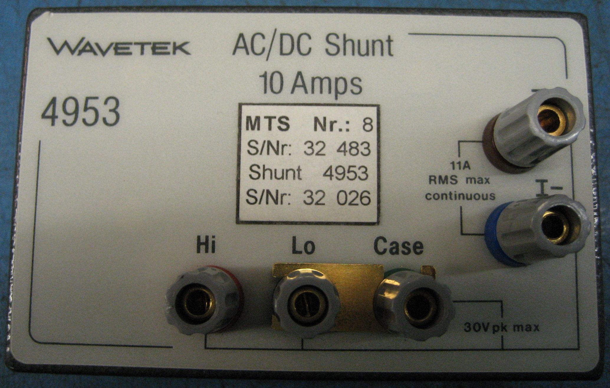
Unit in this article came with full package, including Datron 4953 10A shunt and original Wavetek shipping box.
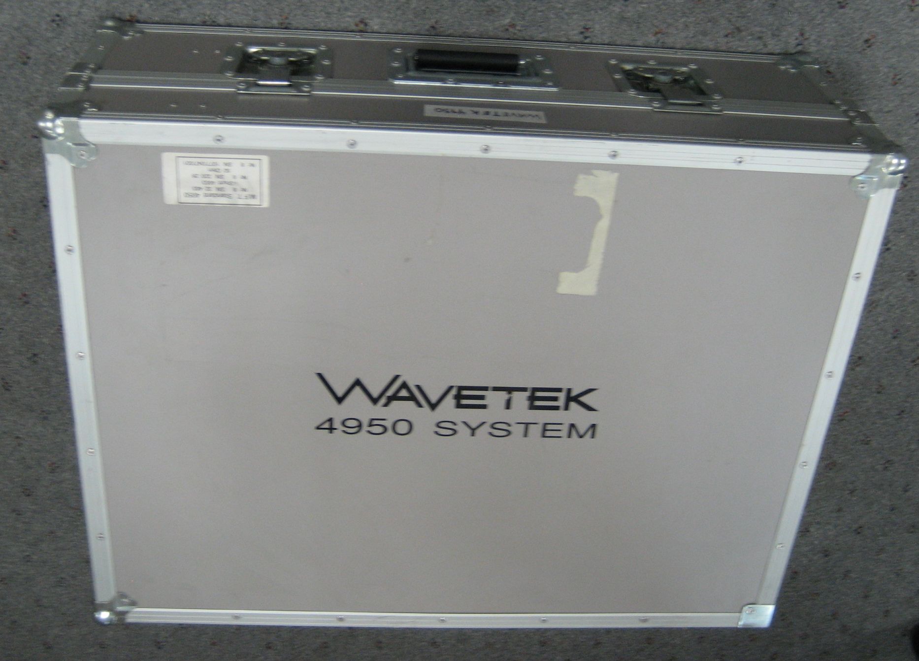
Box also have temperature and humidity meter. Nice touch!
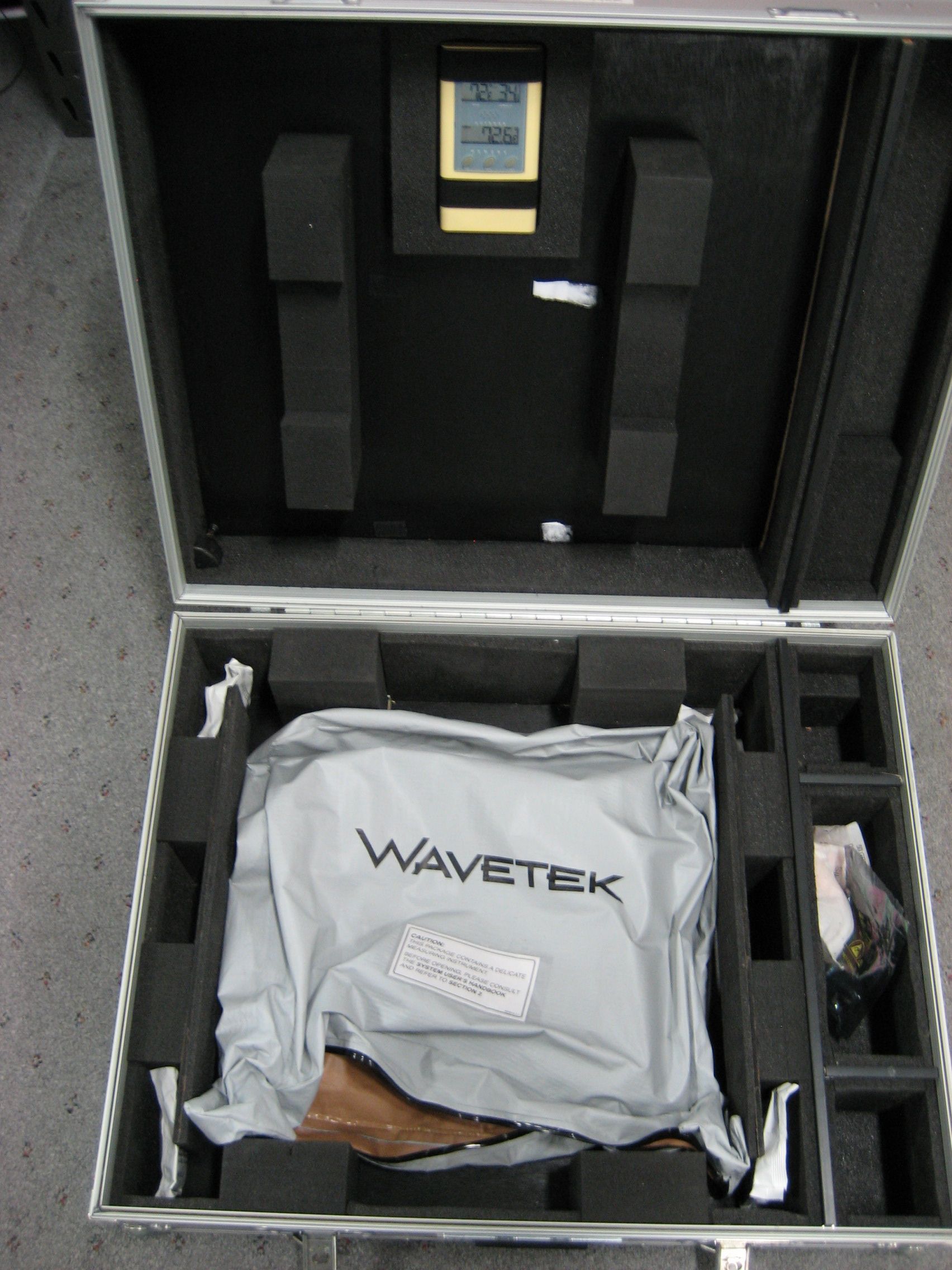
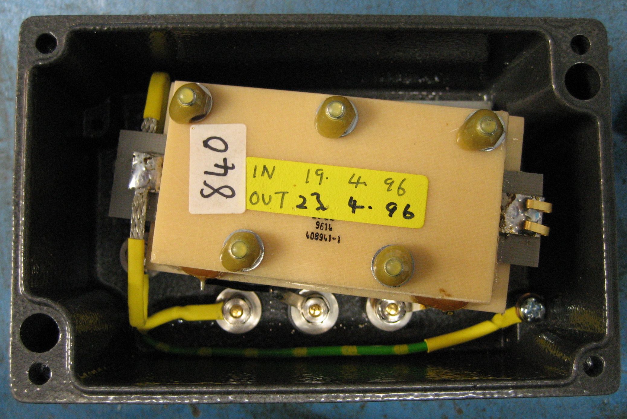
Shunt photos and peek inside:
Disclaimer
Redistribution and use of this article or any images or files referenced in it, in source and binary forms, with or without modification, are permitted provided that the following conditions are met:
- Redistribution of article must retain the above copyright notice, this list of conditions, link to this page (/fix/w4950/) and the following disclaimer.
- Redistribution of files in binary form must reproduce the above copyright notice, this list of conditions, link to this page (/fix/w4950/), and the following disclaimer in the documentation and/or other materials provided with the distribution, for example Readme file.
All information posted here is hosted just for education purposes and provided AS IS. In no event shall the author, xDevs.com site, or any other 3rd party, including Fluke be liable for any special, direct, indirect, or consequential damages or any damages whatsoever resulting from loss of use, data or profits, whether in an action of contract, negligence or other tortuous action, arising out of or in connection with the use or performance of information published here.
Manual references related to Datron 1281/1271, 4920 and 4950
Wavetek Model 4950, Instrument User’s Handbook, Issue 4, December 1998
Wavetek Model 4950 Specifications
We are not lucky enough to have schematics or service manual for Model 4950 MTS. If you have this information, please upload to our repository by following these simple instructions
Datron 1281 DMM documentation.
Datron Model 1281/1271 Datasheet and specification
Datron 1281 Users manual, Issue 6, Feb 1999
Datron 1281 Calibration and service manual, Volume 1 and 2, Issue 1, July 1989
Datron 1281 Calibration and service manual with schematics, Volume 2, Issue 2, January 1989
Datron 1281 Calibration and service manual with schematics, Volume 2
There are also useful manuals for similar Datron DMM, Model 1271. Credits for storing these manuals goes to KO4BB. Here’s mirror of them:
Datron 1271 Service manual, Calibration and servicing
DJVU-format files can be opened with freeware WinDjView from Djvu.org.
Initial inspection and basic disassembly and service
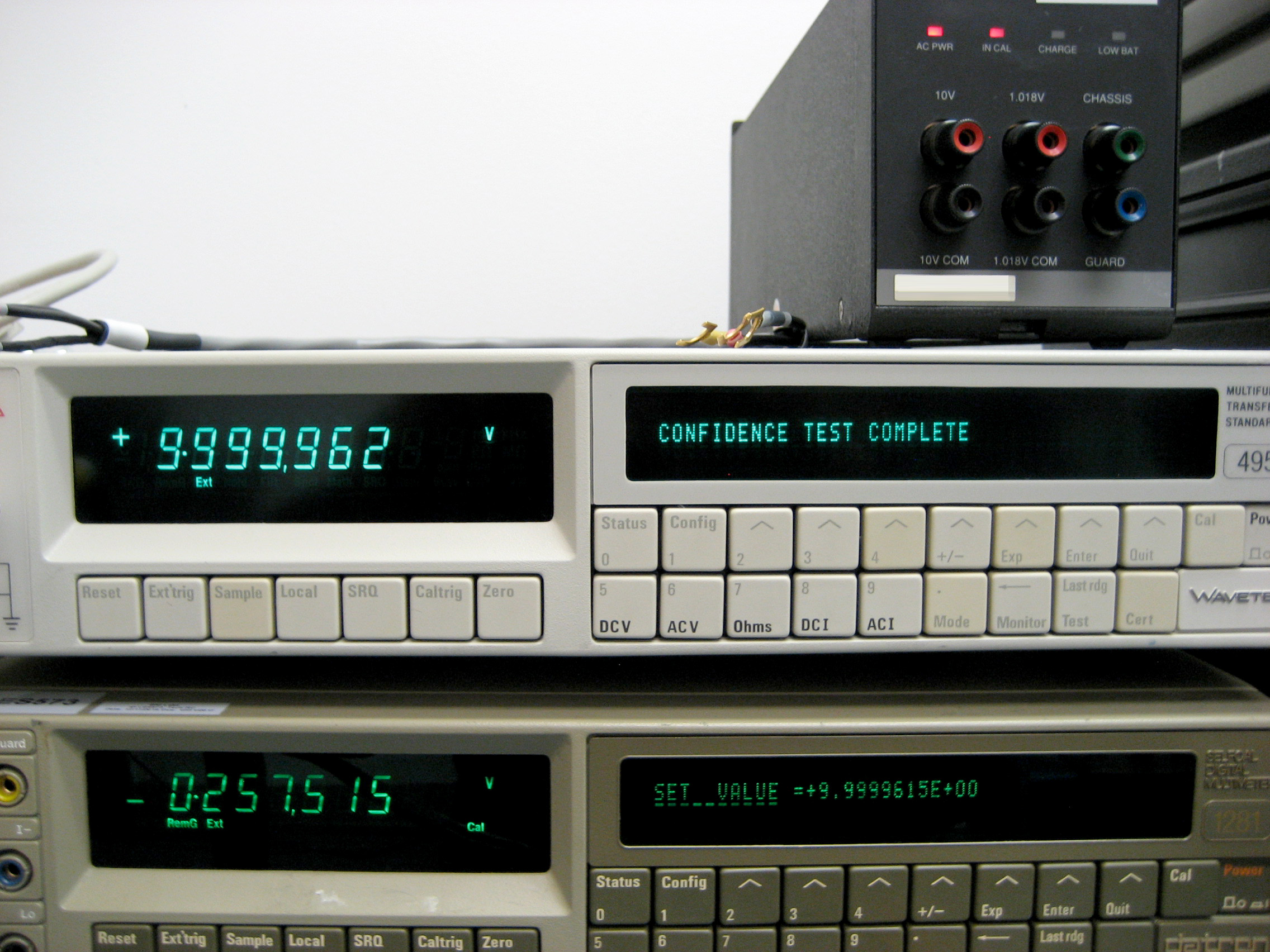
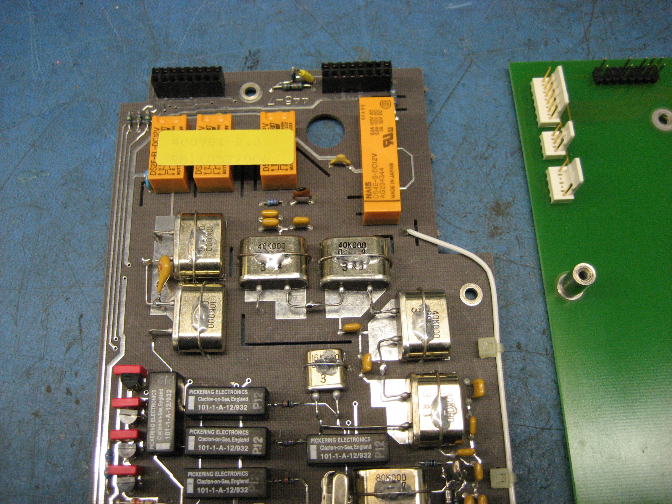
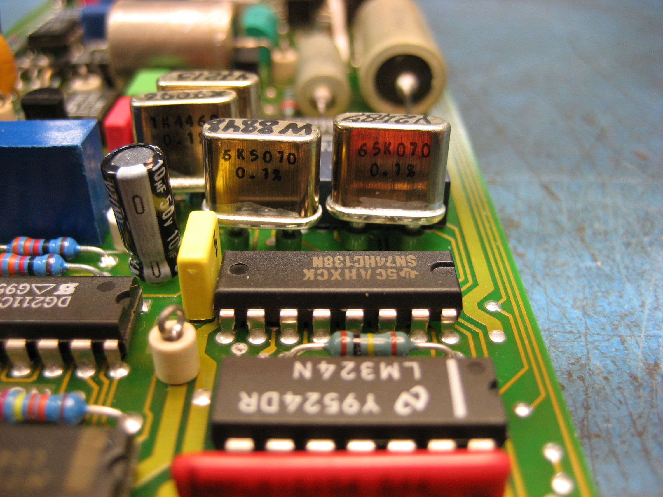
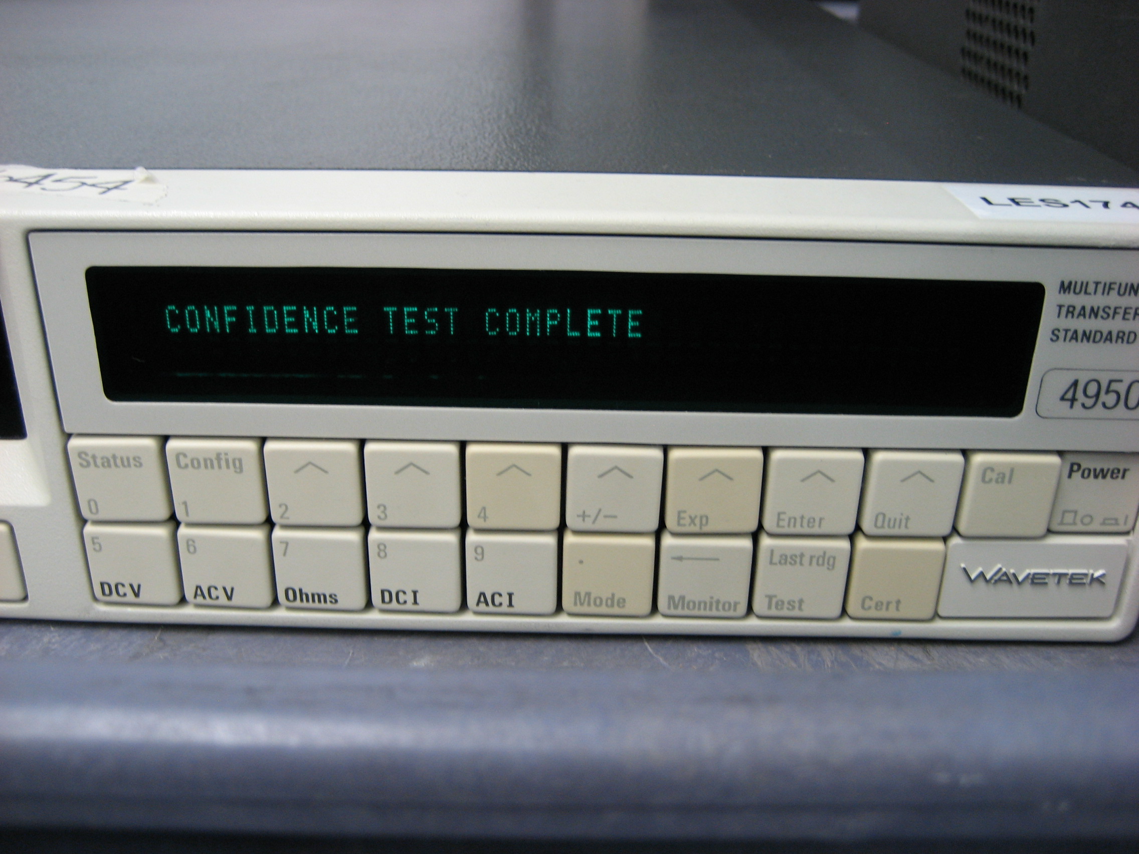
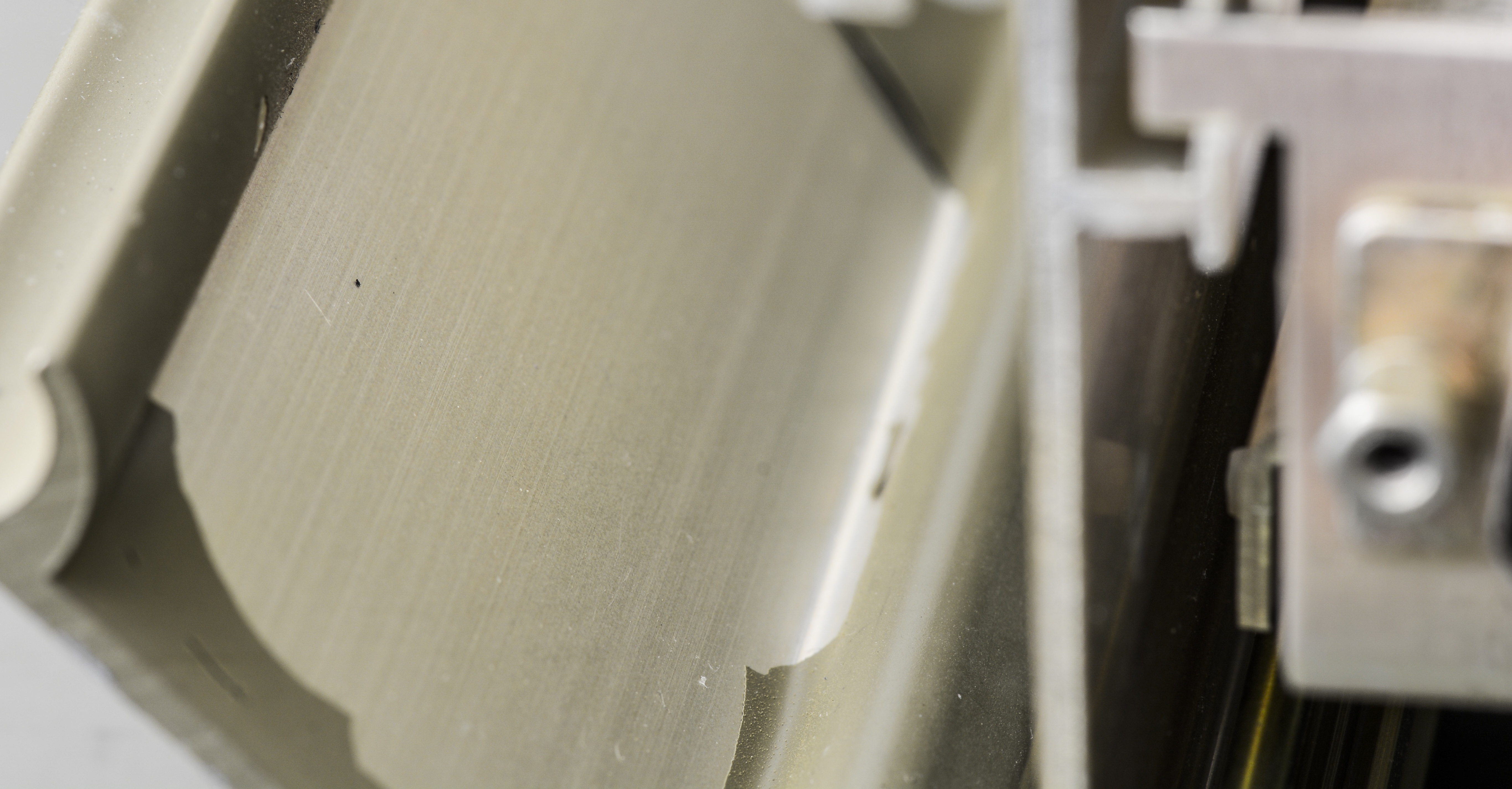
The unit was purchased used, in operational condition. I was asked to go over the unit before it was put into service in our calibration lab. Physically the unit was found to be in very good condition. There was no damage to the exterior, all of the hardware was present, and all of the buttons mechanically operated OK. The covers were then removed for a visual internal inspection. The covers of 5 ceramic DIP ICS were separated from the body of the IC. According to the schematics these are resistor arrays. I inspected them under the microscope and no obvious damage was apparent to the bonding wires and the resistors measured good with a DVM. I located the missing covers in the bottom of the unit and reinstalled them using epoxy. Further inspection of the interior of the unit looked good, this unit does not have any vents to allow dirt or dust accumulation. All of the hardware was present, there was no obvious damage (IE burn marks or excess heat), and there was no leaking or bulging of the electrolytic capacitors. I powered the unit up for an initial functional test. There is a 6 hour warm-up period for the 4950. A battery backed ICM7170 real time clock keeps the time, and if the unit has been turned off for a short period of time a new warm up period will be calculated, so a full 6 hours will not be required every time the unit is powered off. After warm up I successfully ran the confidence test and took a couple of quick measurements to test the unit.
I usually replace all electrolytic capacitors, opto-isolators, single wipe sockets, batteries and fans during a refurbish. I also visually inspect the boards, and remove and reapply thermal compound. This unit only required new capacitors, opto-isolators, and back-up battery. Several of the 1uf capacitors had low capacitance and high ESR. Visual inspection revealed bad solder connections on the ??? board.
After assembly the unit would not pass its confidence test. Troubleshooting revealed a solder bridge on one of the capacitors. I re-soldered the connection and the unit passed all of its confidence tests.
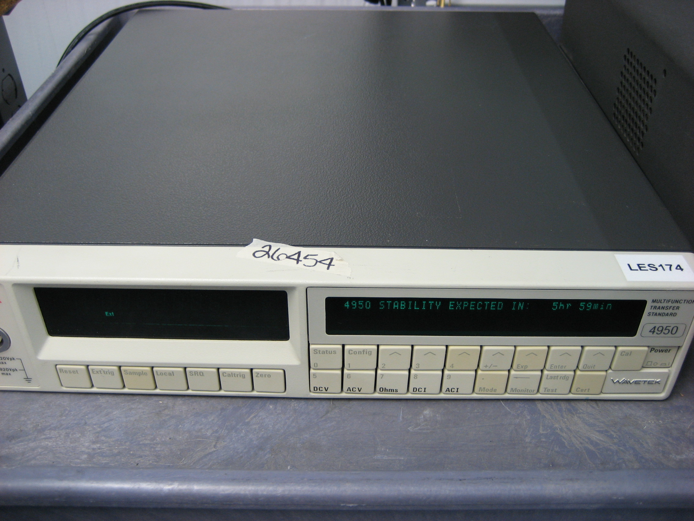
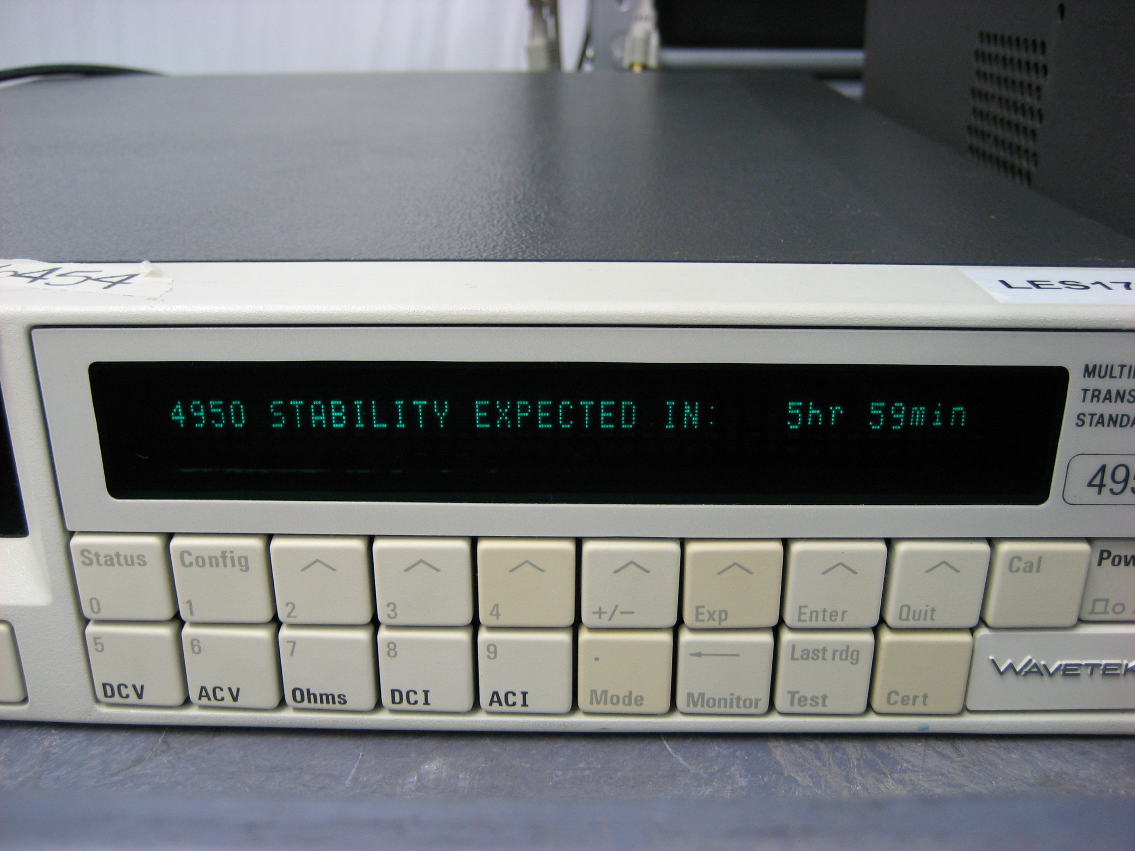
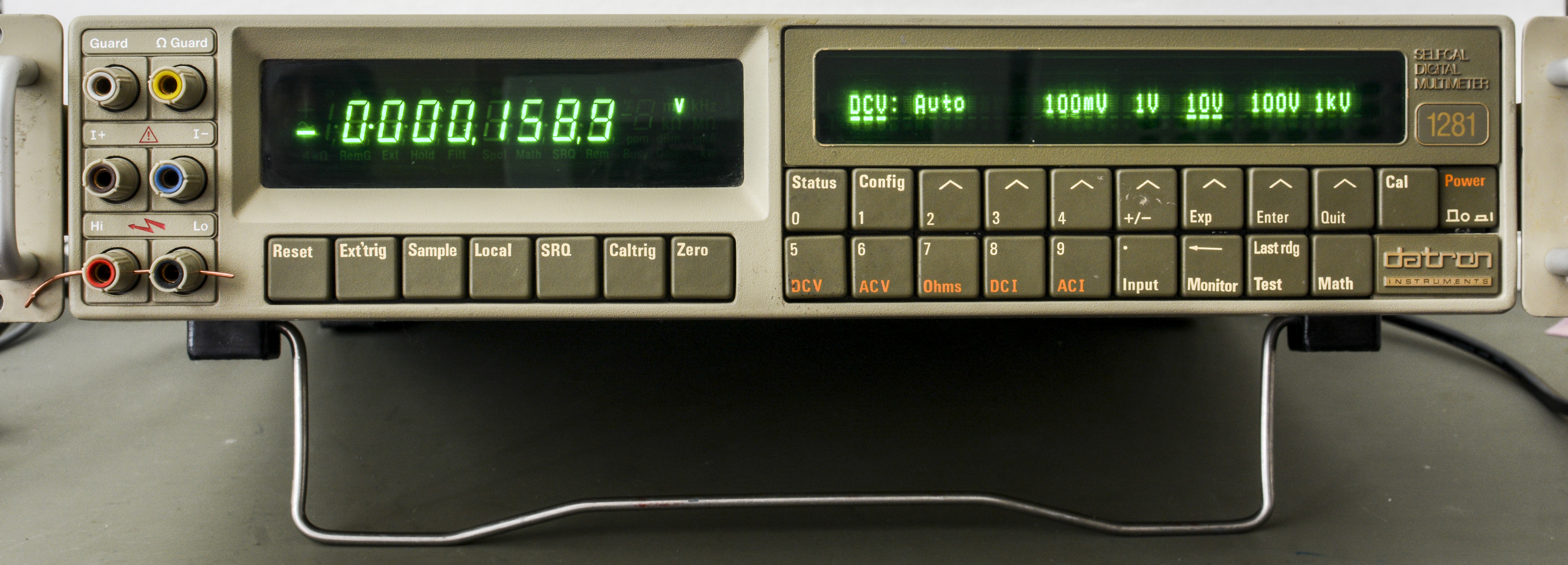
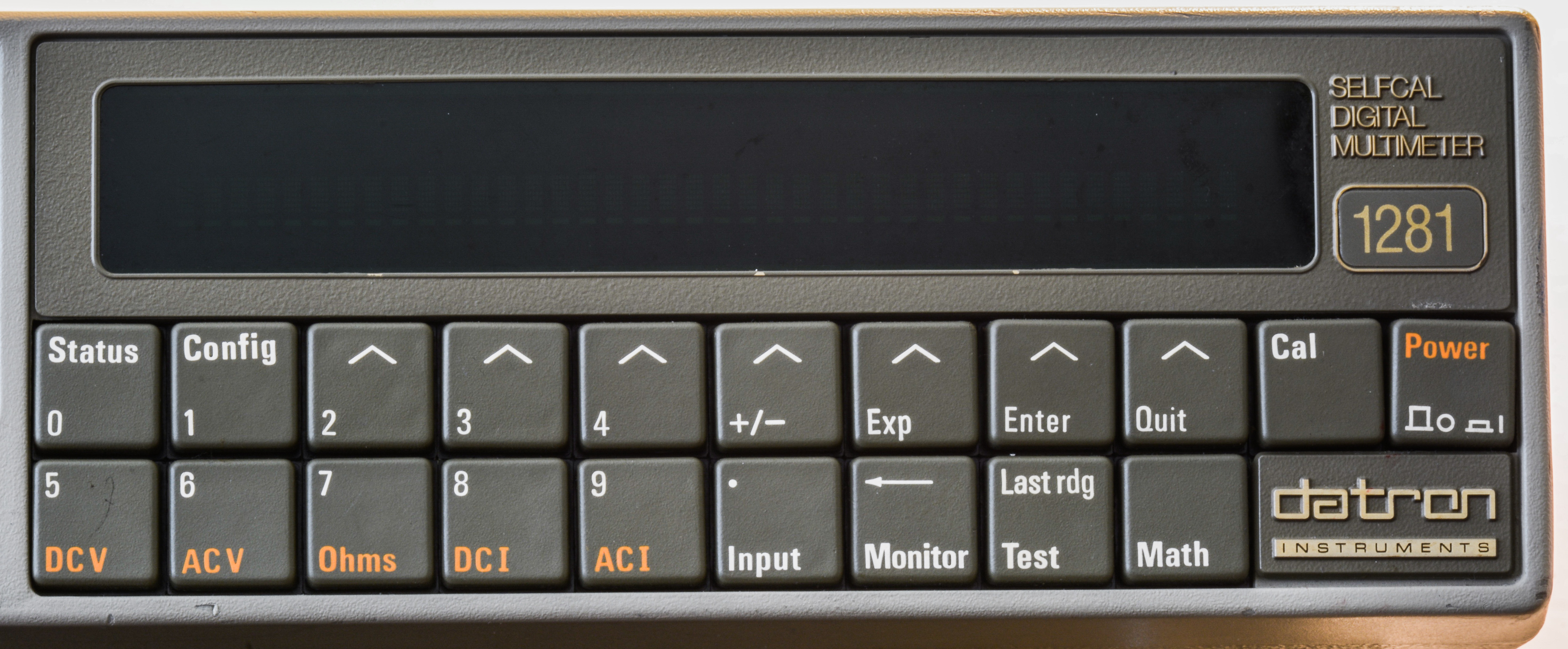
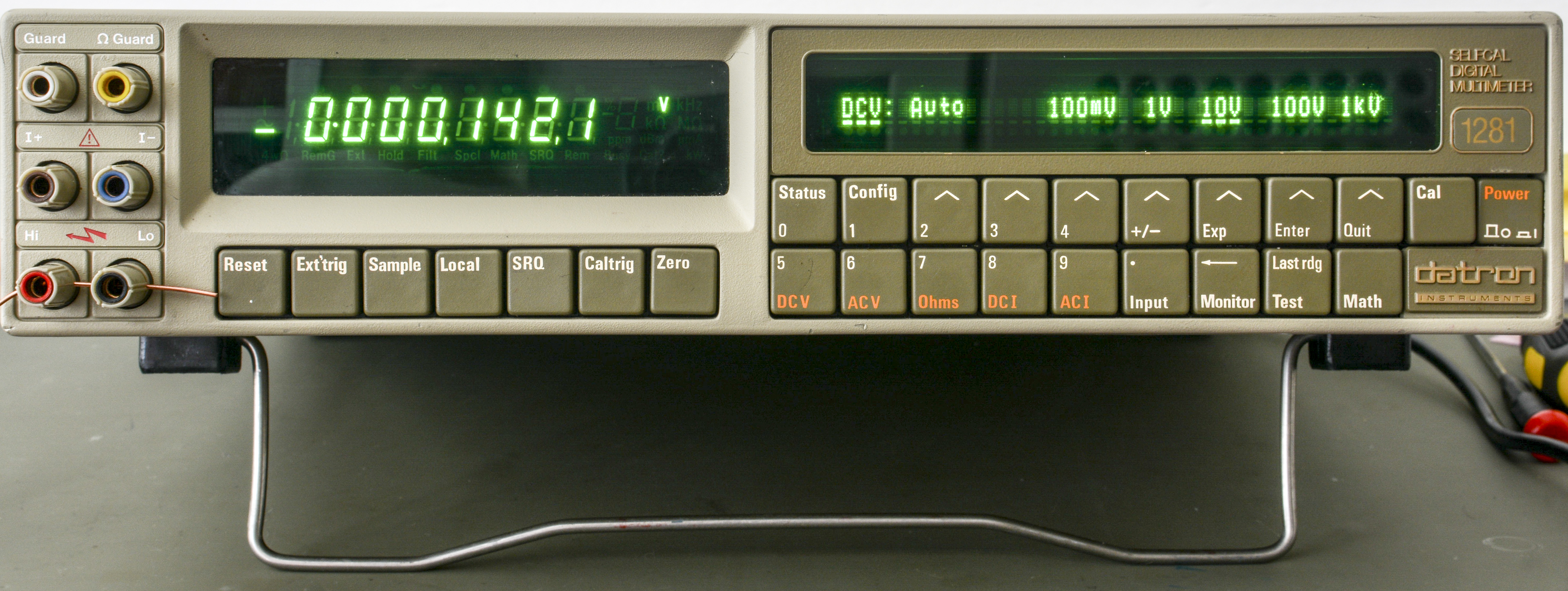
Image 1: Wavetek 4950 front face
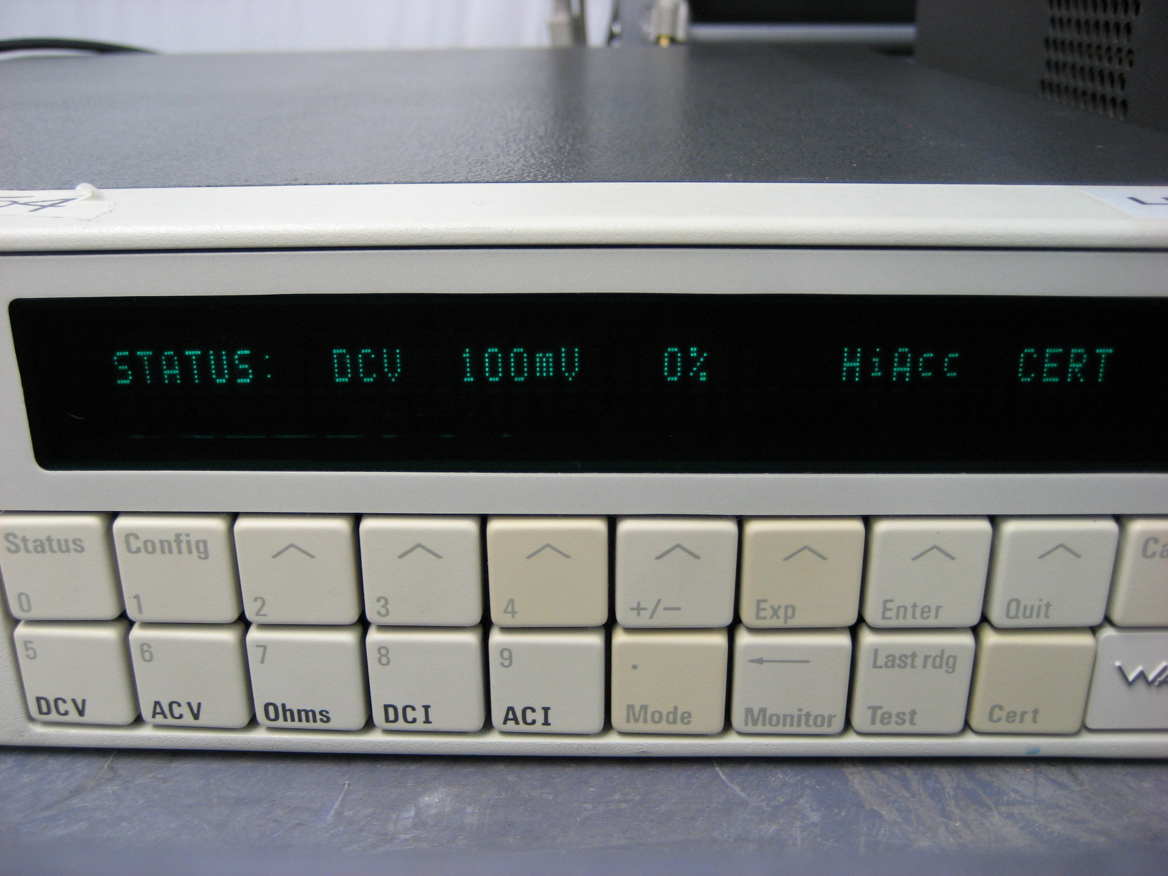
Display is custom, model DC405E2 from ITRON/Japan, same used in Datron 1271/1281 and 4920/4920M. Display size is 1×40 char, 5×7 DOT matrix, 5mm height. Itron does not have any stock for the display and do not have public documentation for it. But thankfully, we got and able to share full datasheet for DC405E2.

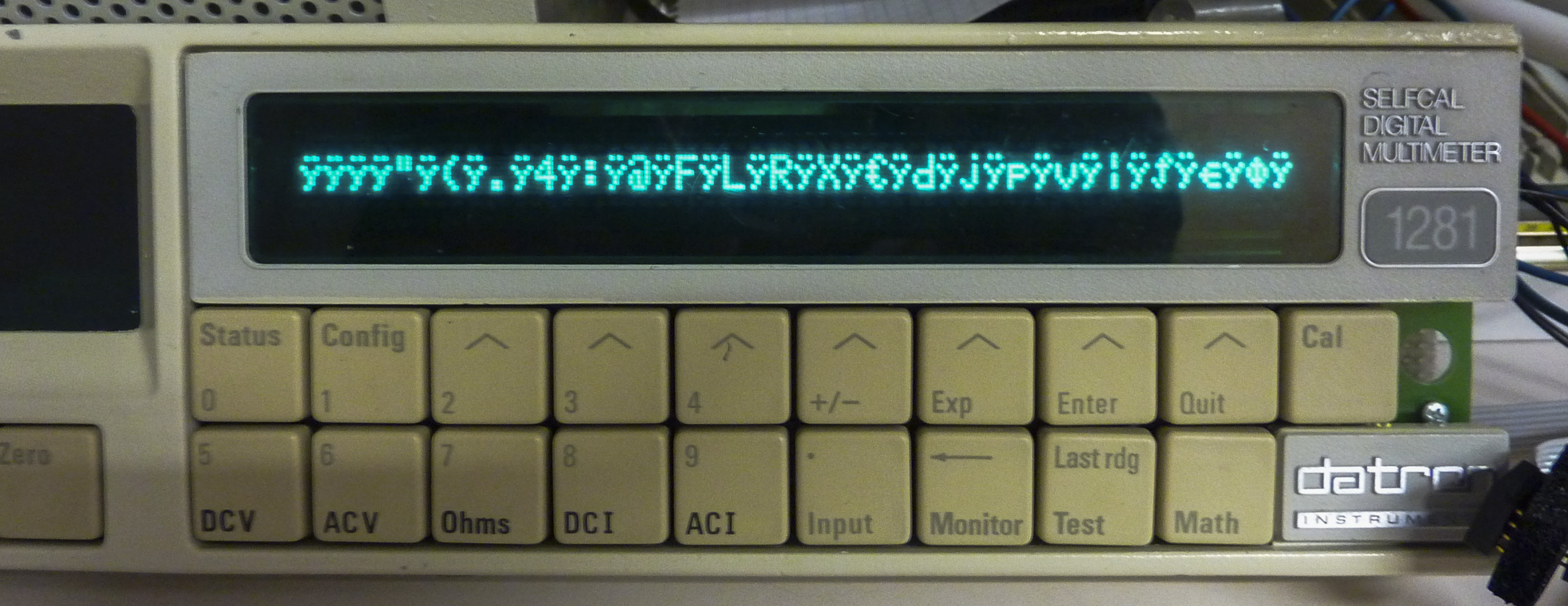
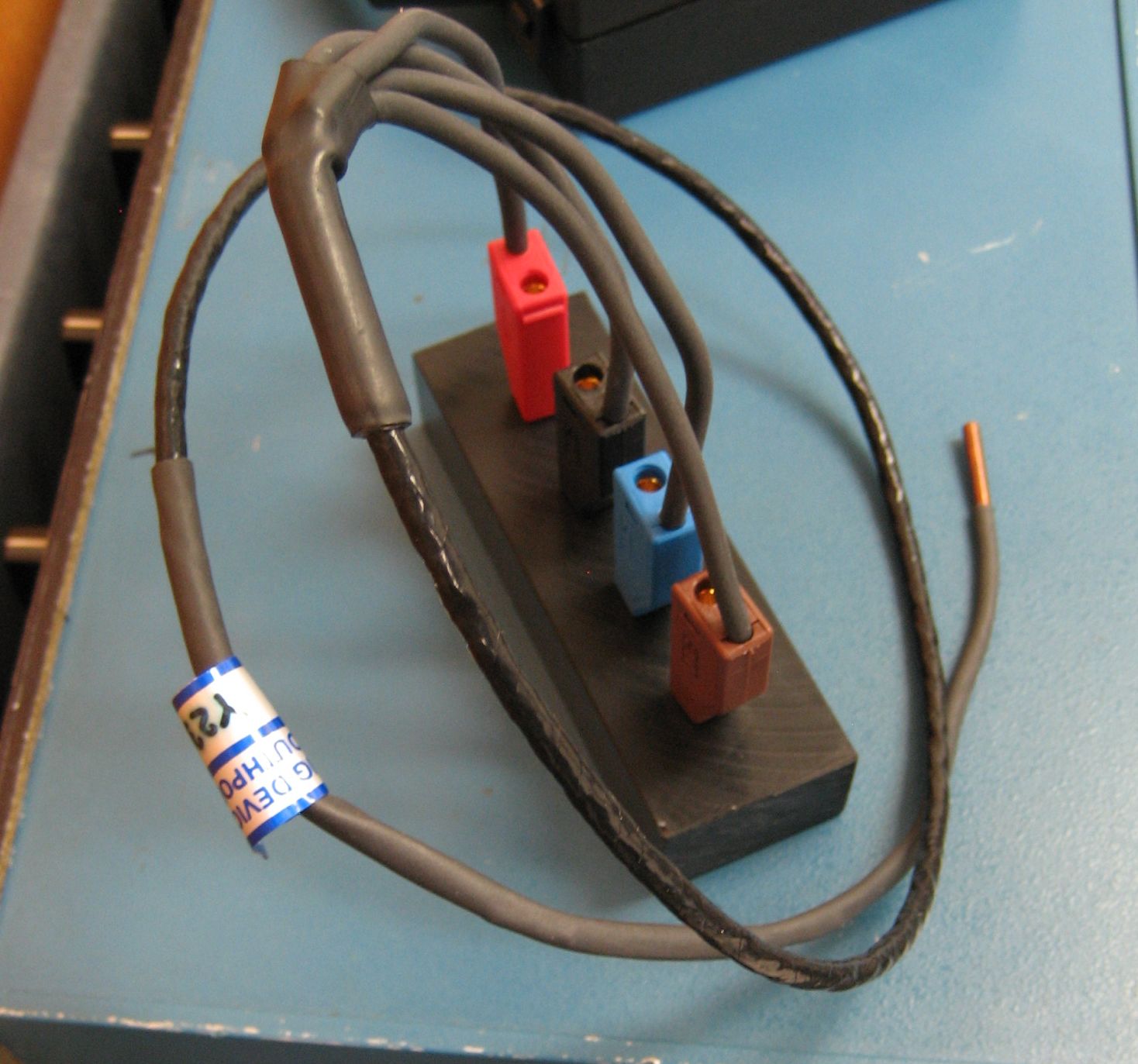
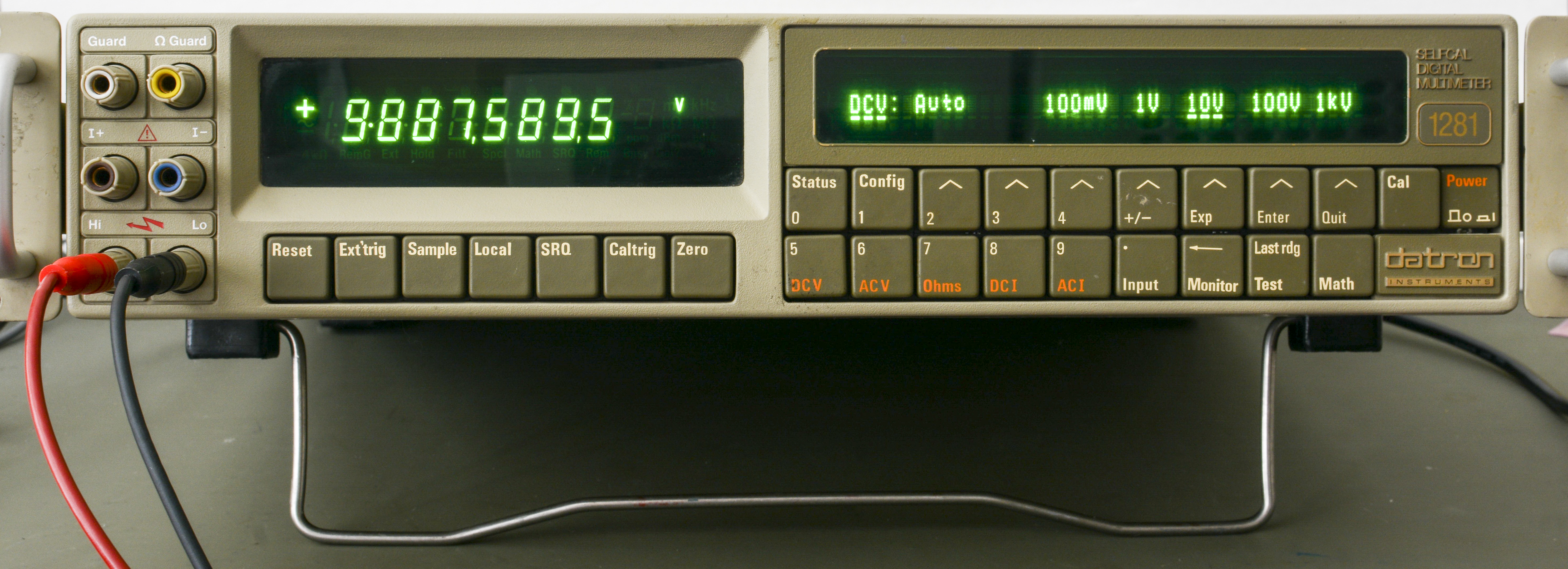
Image 3: Testing VFD display output and test connections
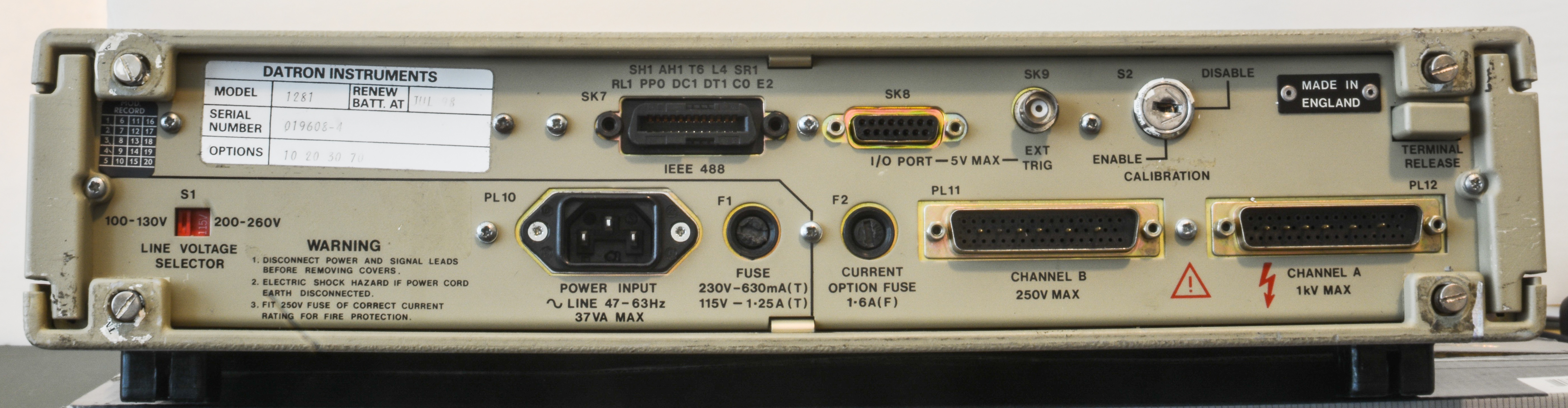
Image 4: DMM rear face
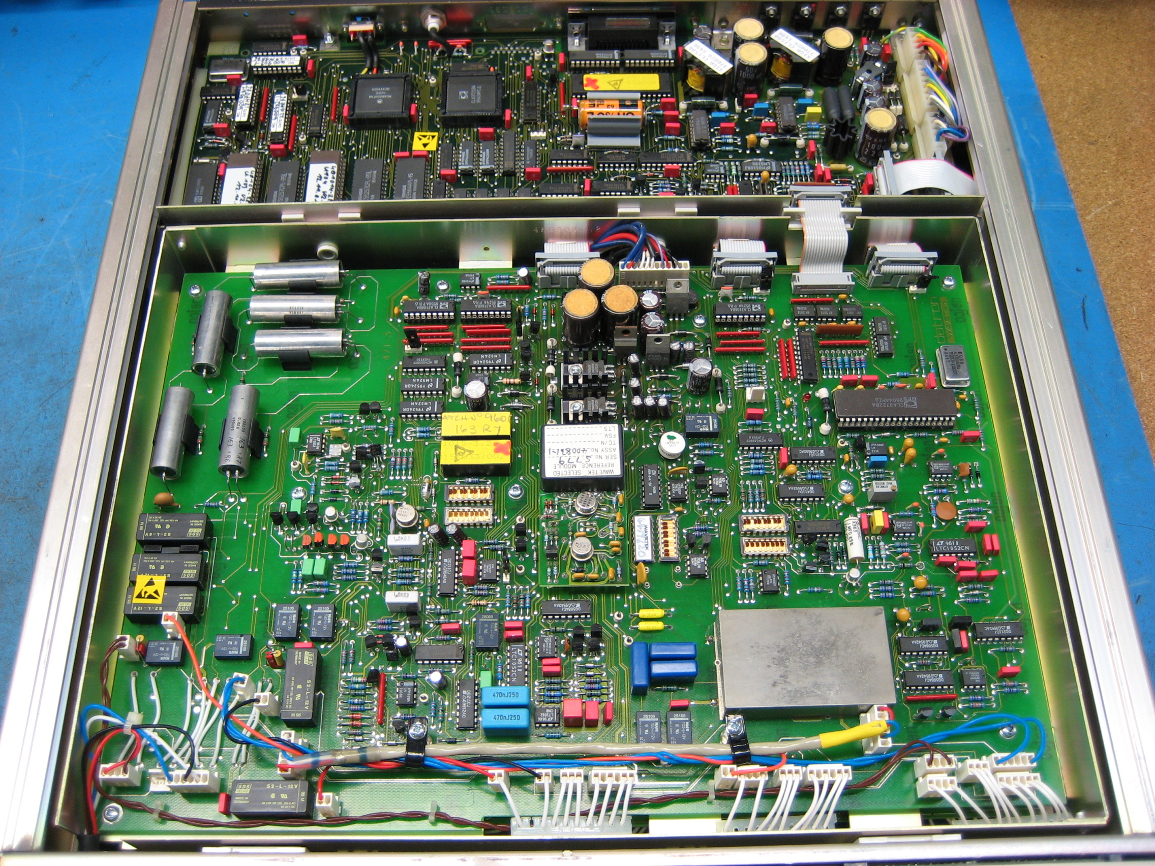
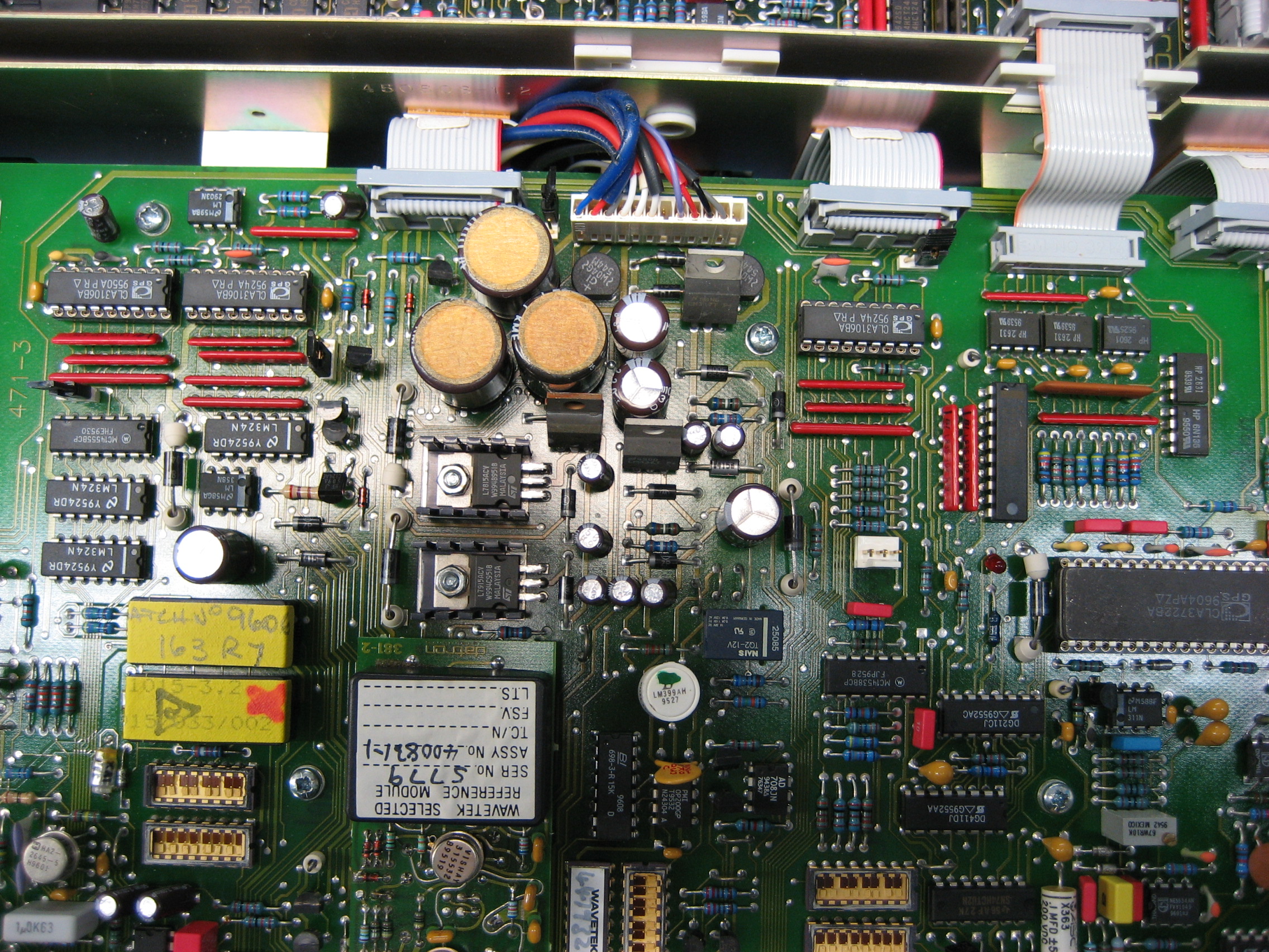
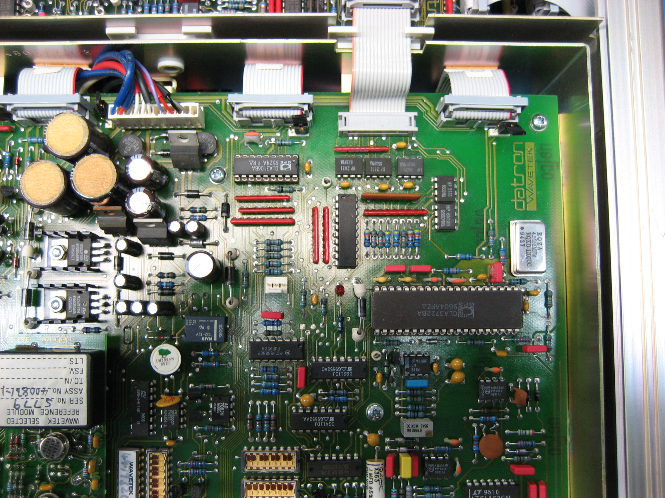
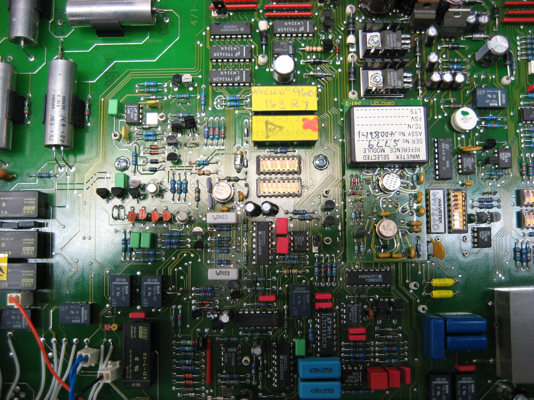
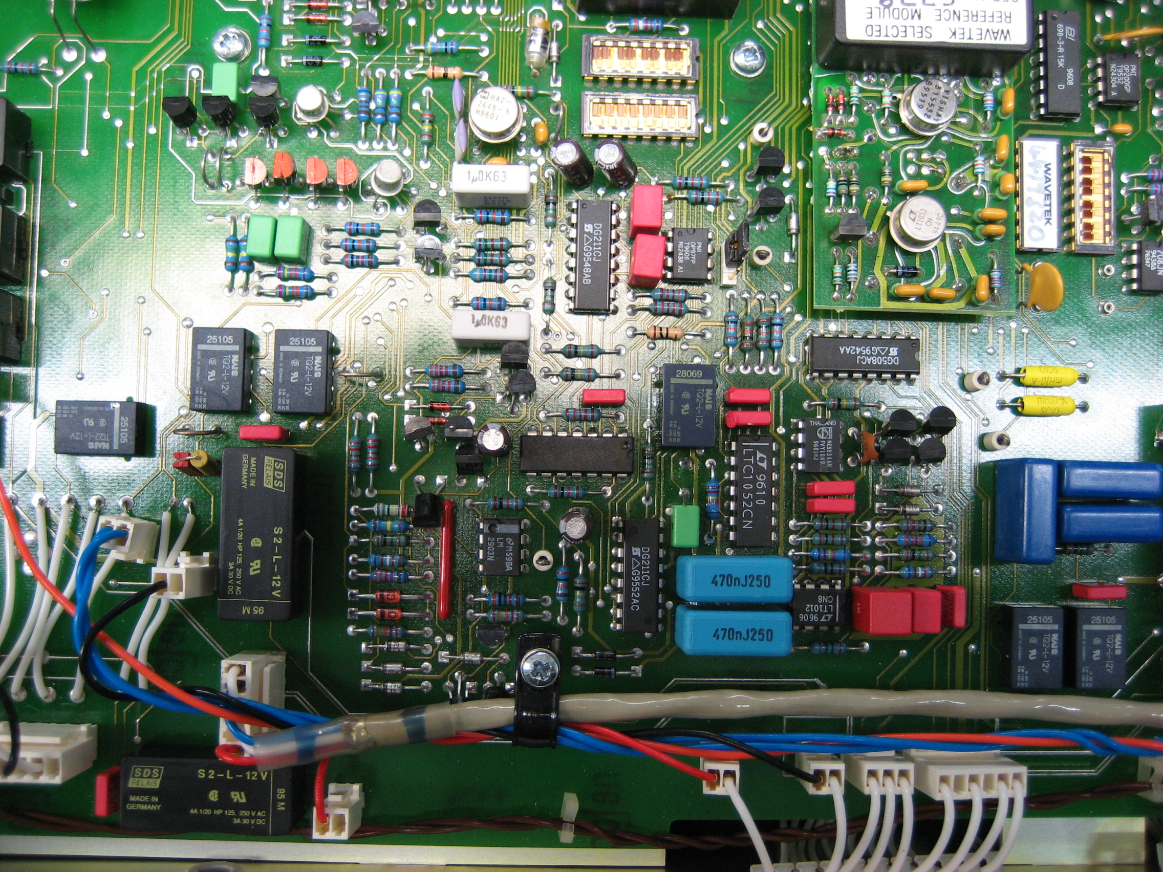
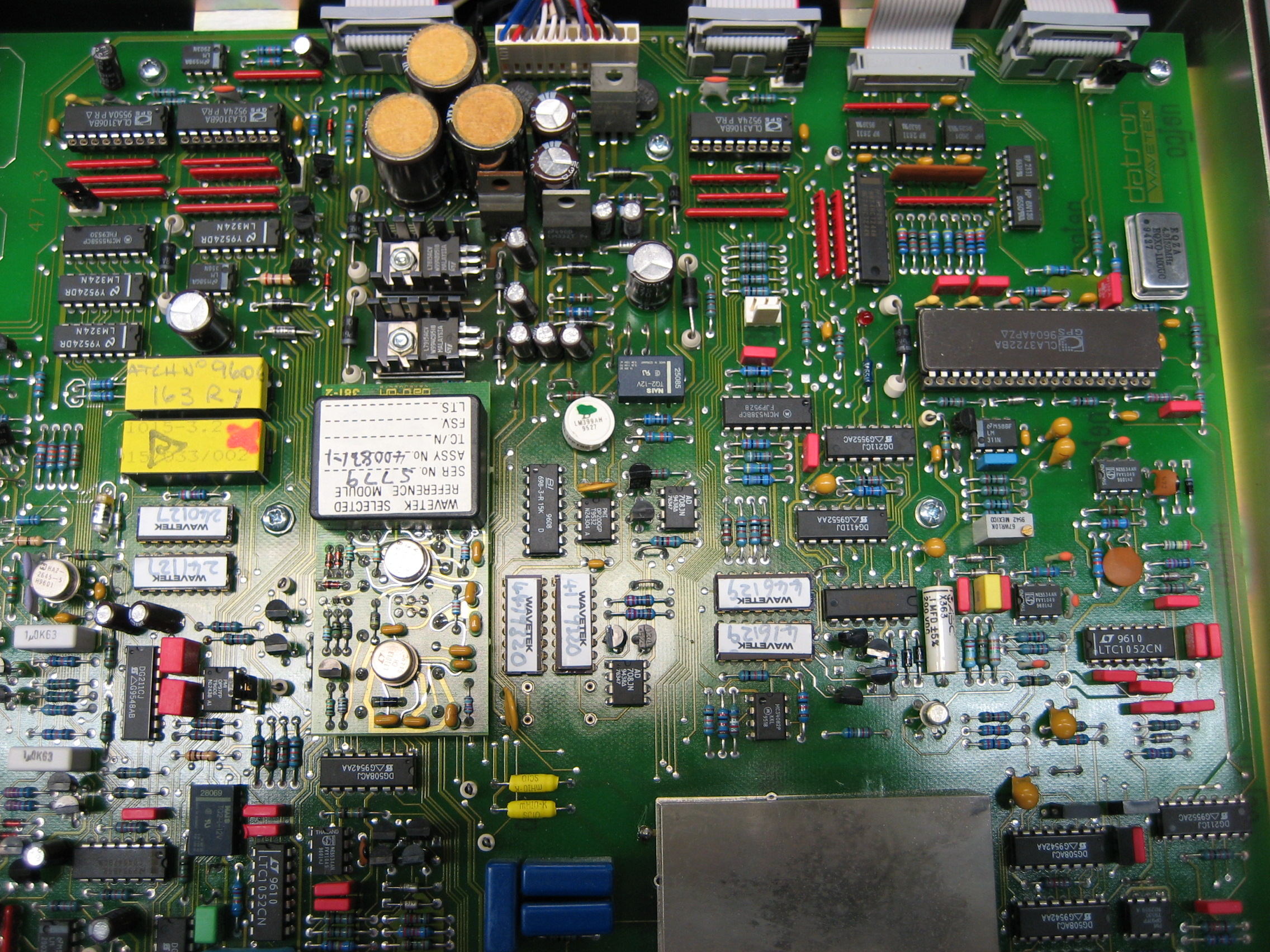
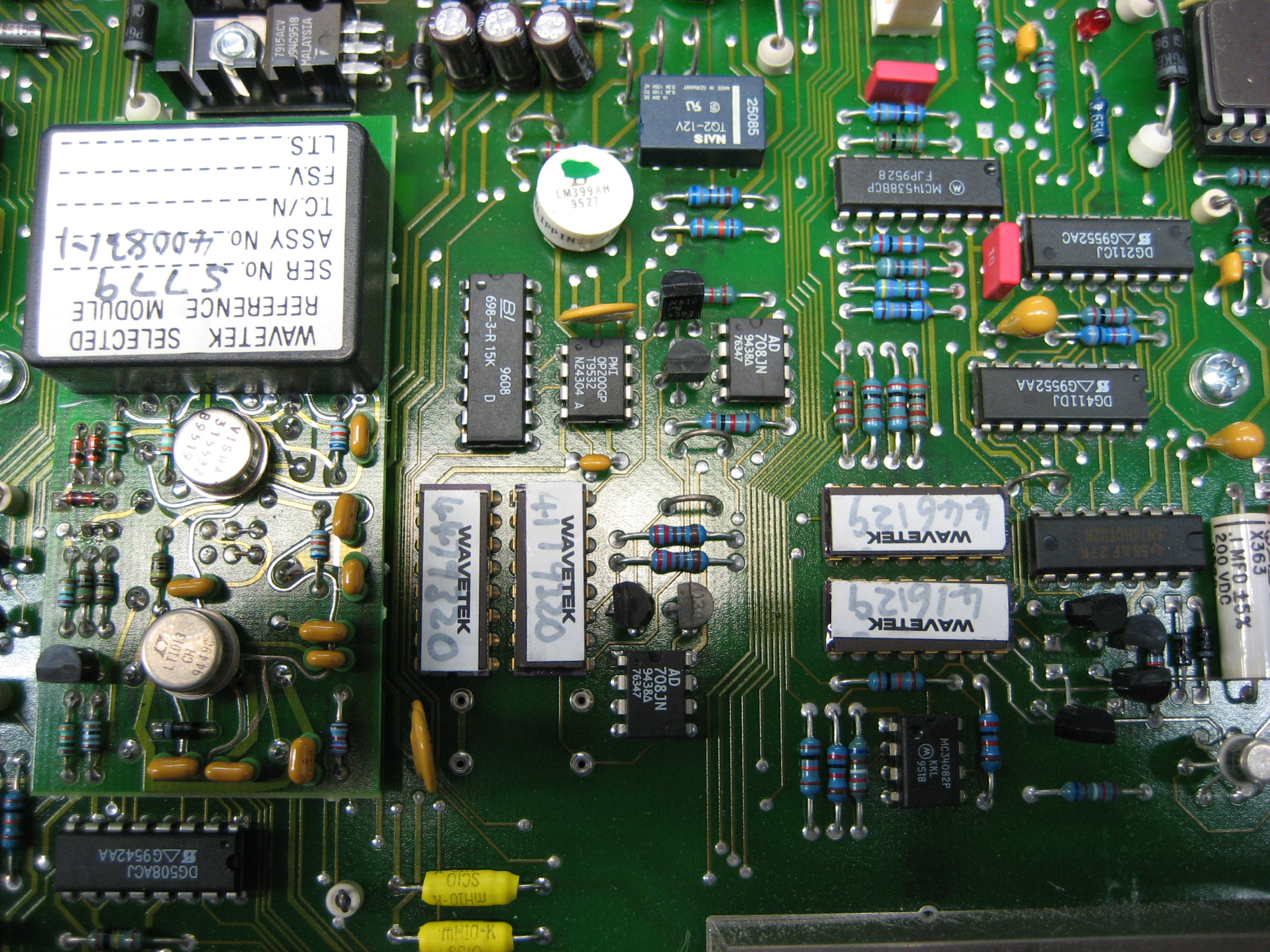
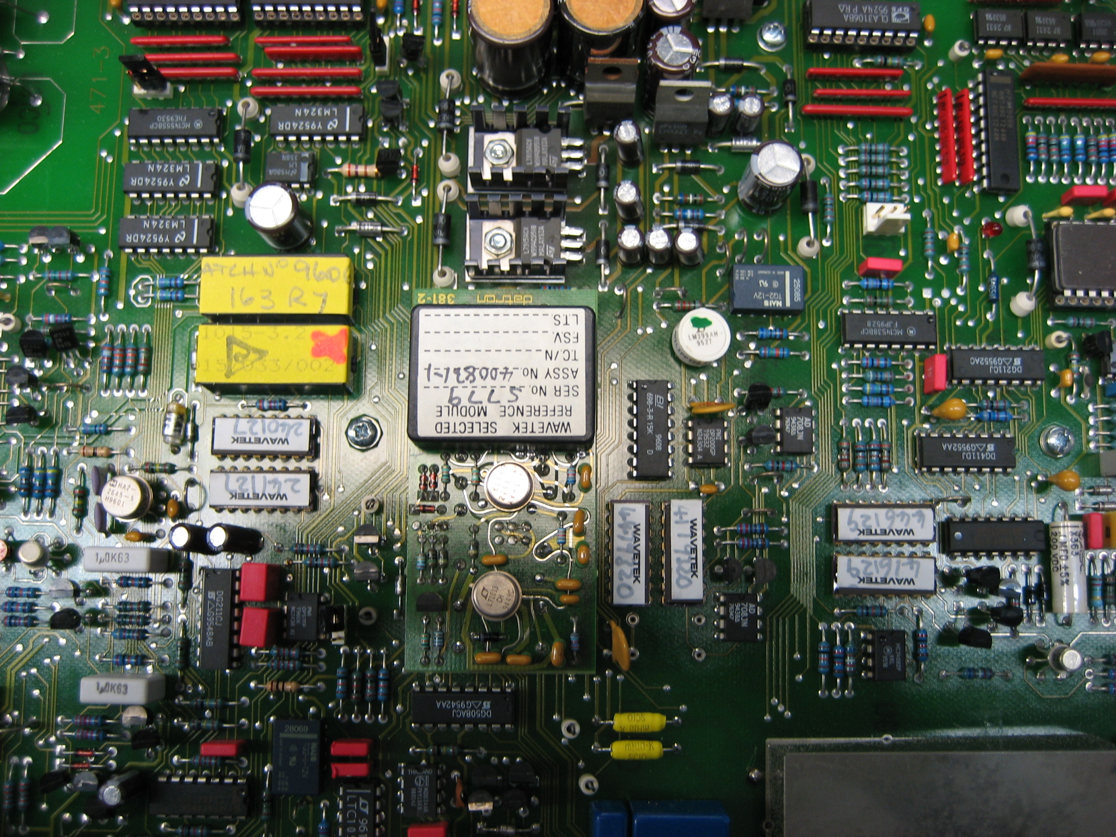
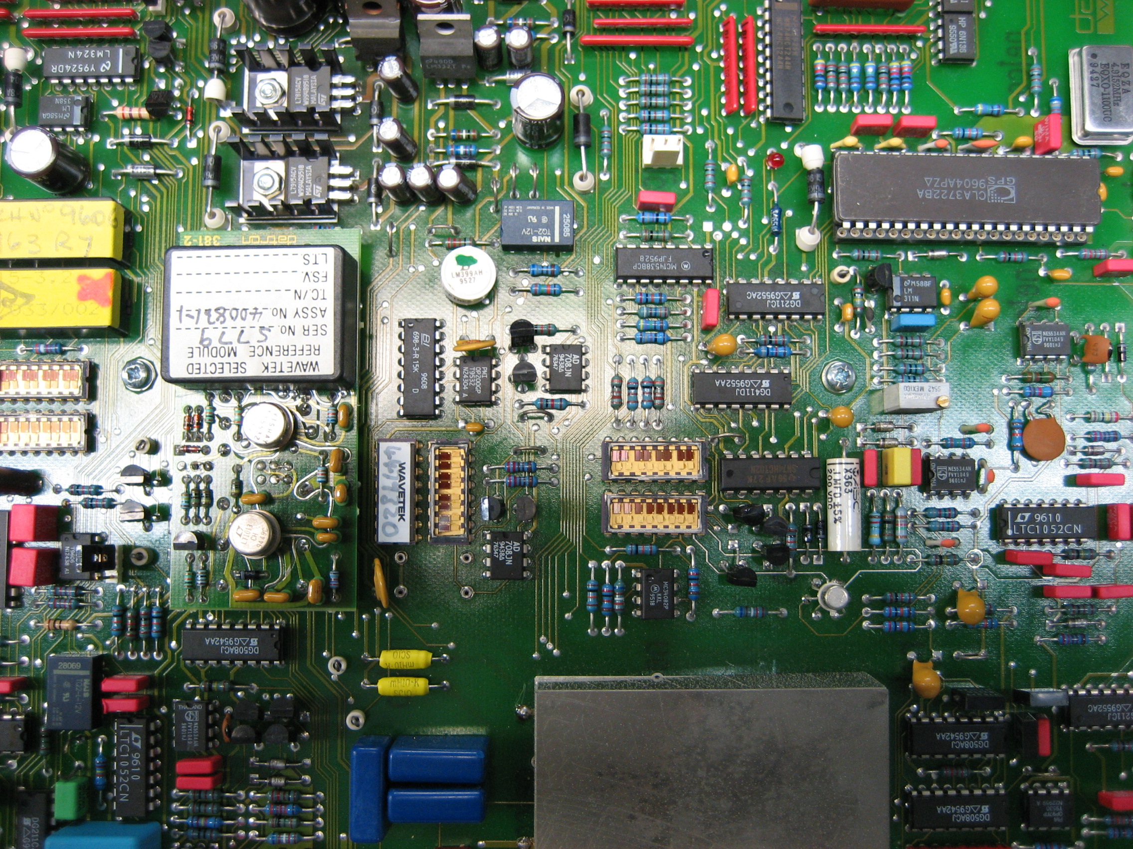
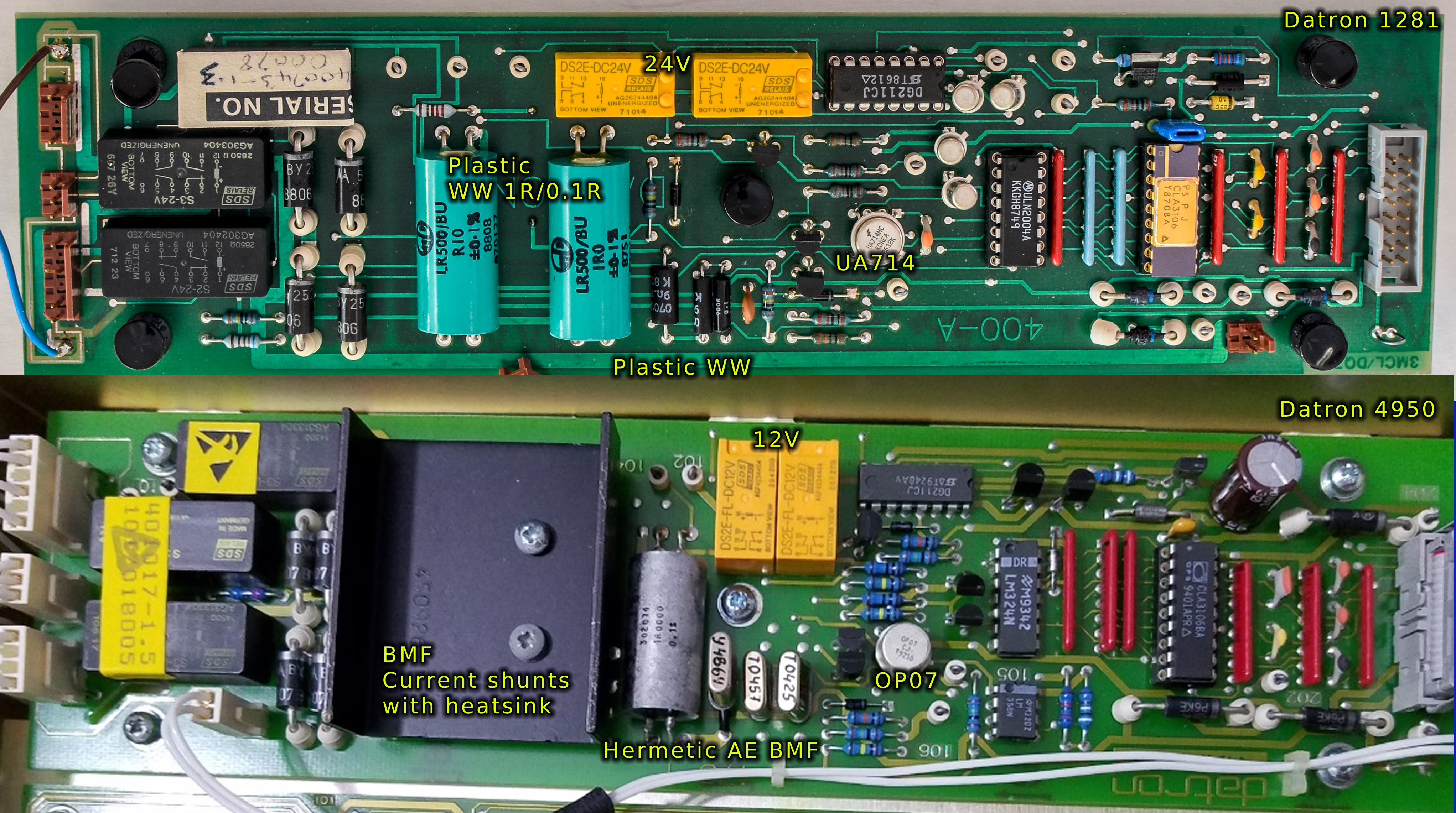
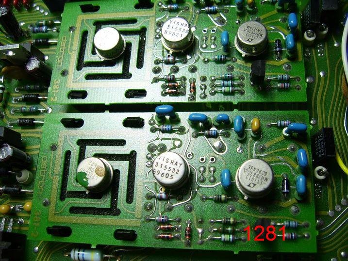
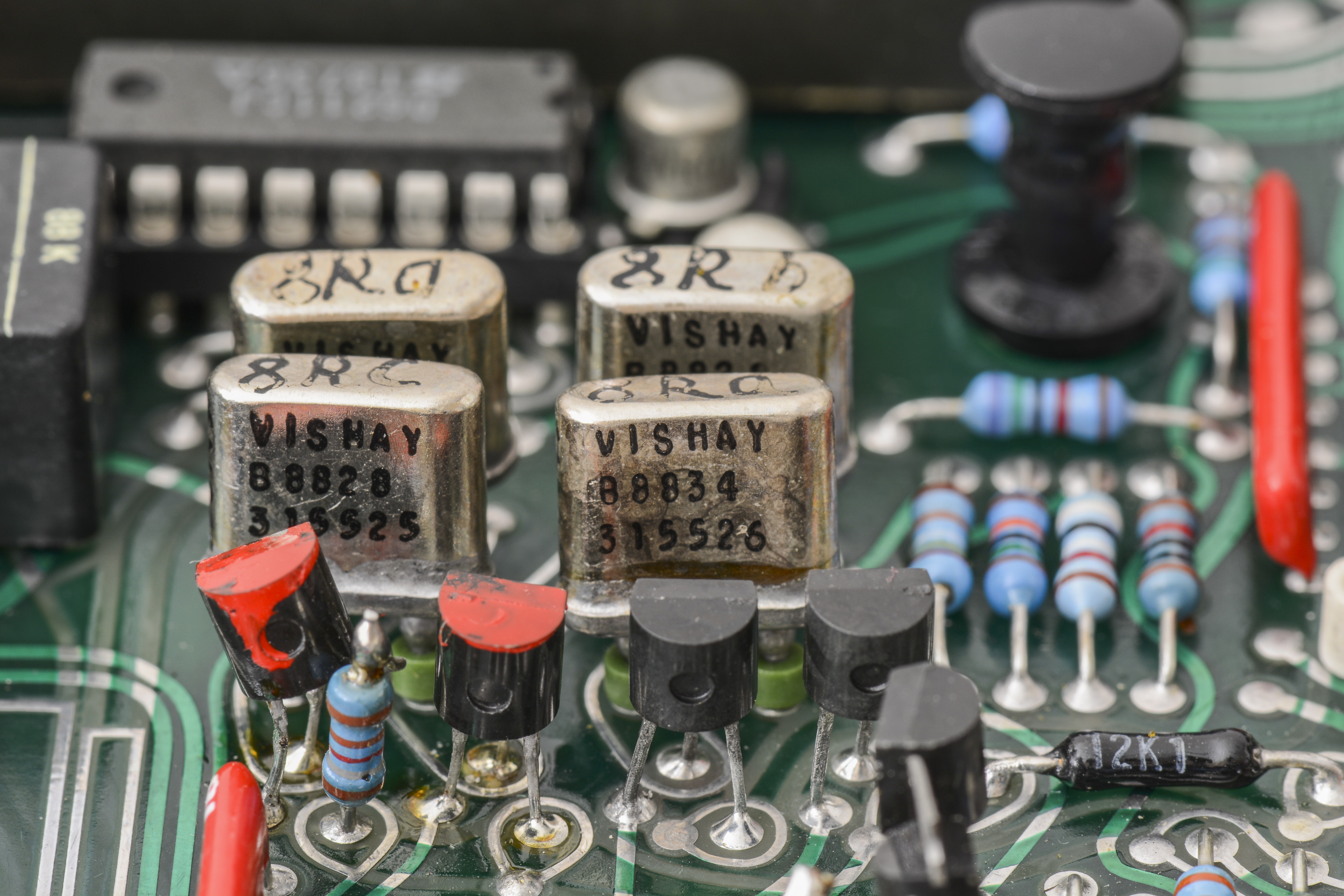
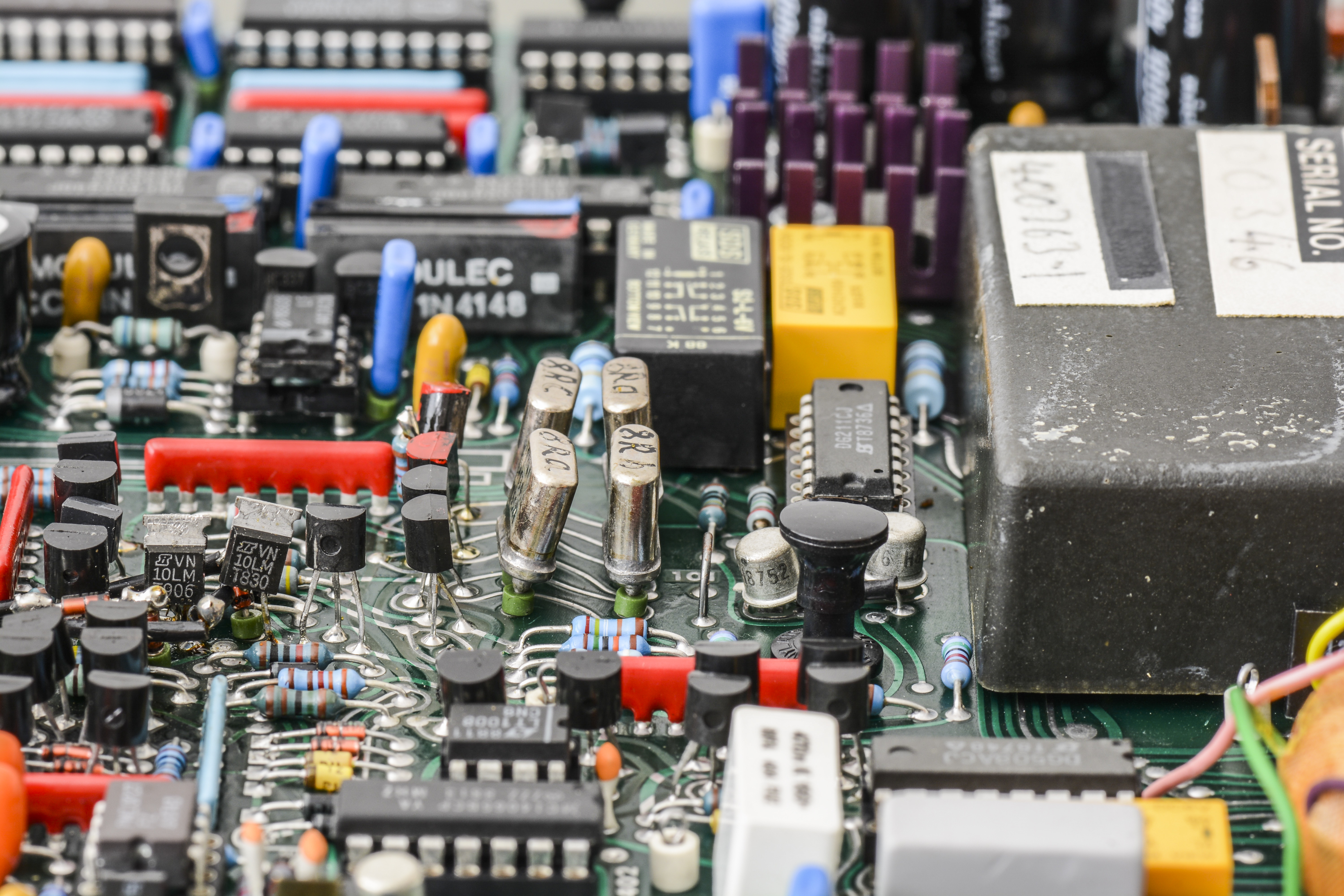
The reference used in the analog to digital conversion is derived from a specially conditioned Linear LTZ1000-based buried zener reference module. It contains the reference device and its associated support circuits, such as Linear LT1013 opamp and Vishay Precision Group BMF resistor network. All critical parts are packaged in hermetic metal cans to avoid humidity effects. The module is tested to be stable within ±4 ppm per year, produces noise less than 0.1 ppmpeak-peak, and has a temperature coefficient better than 0.15 ppm/°C. This temperature coefficient is held over a wide temperature span of 0°C to +70°C, and the reference exhibits negligible temperature shock hysteresis.
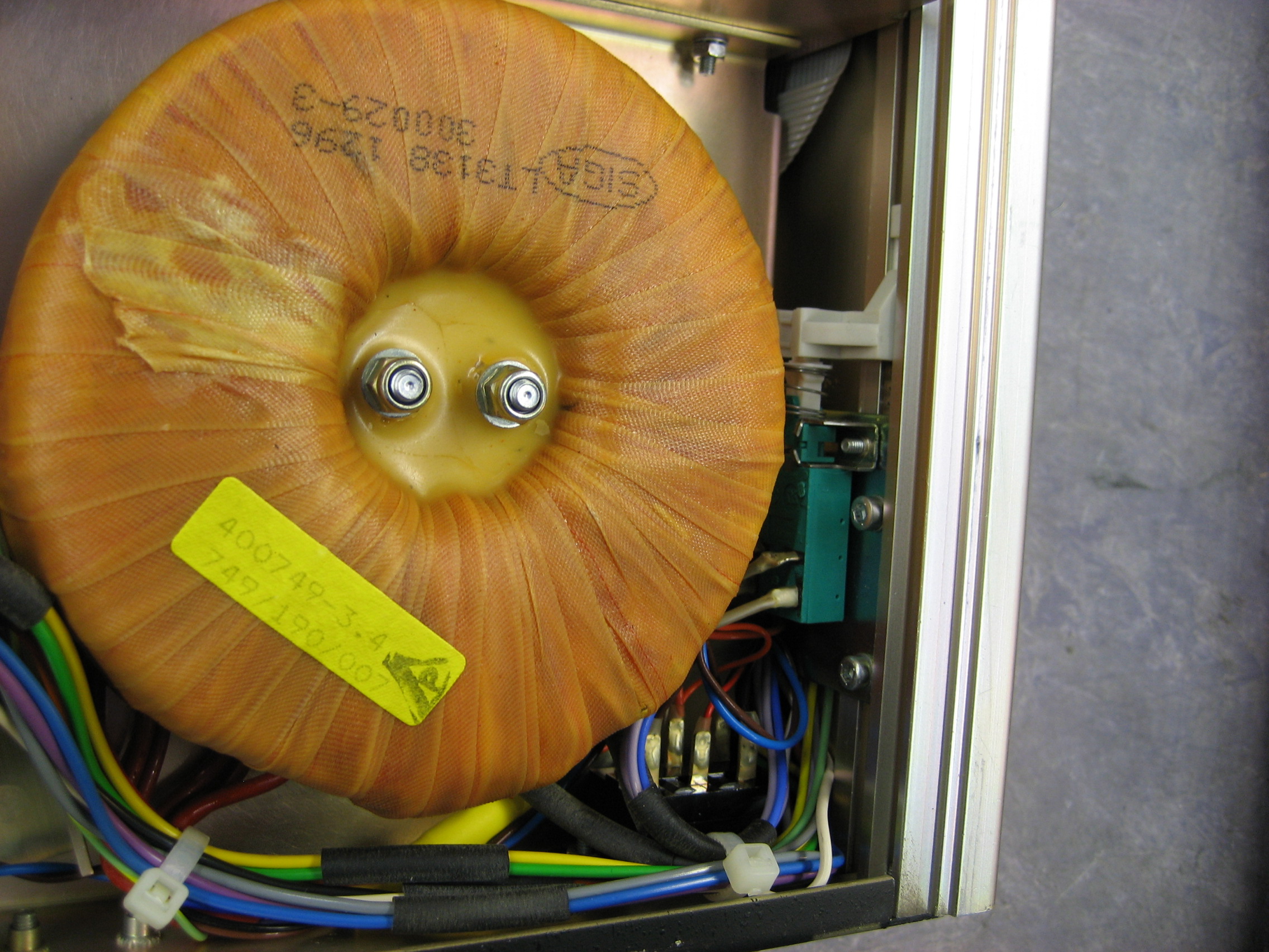
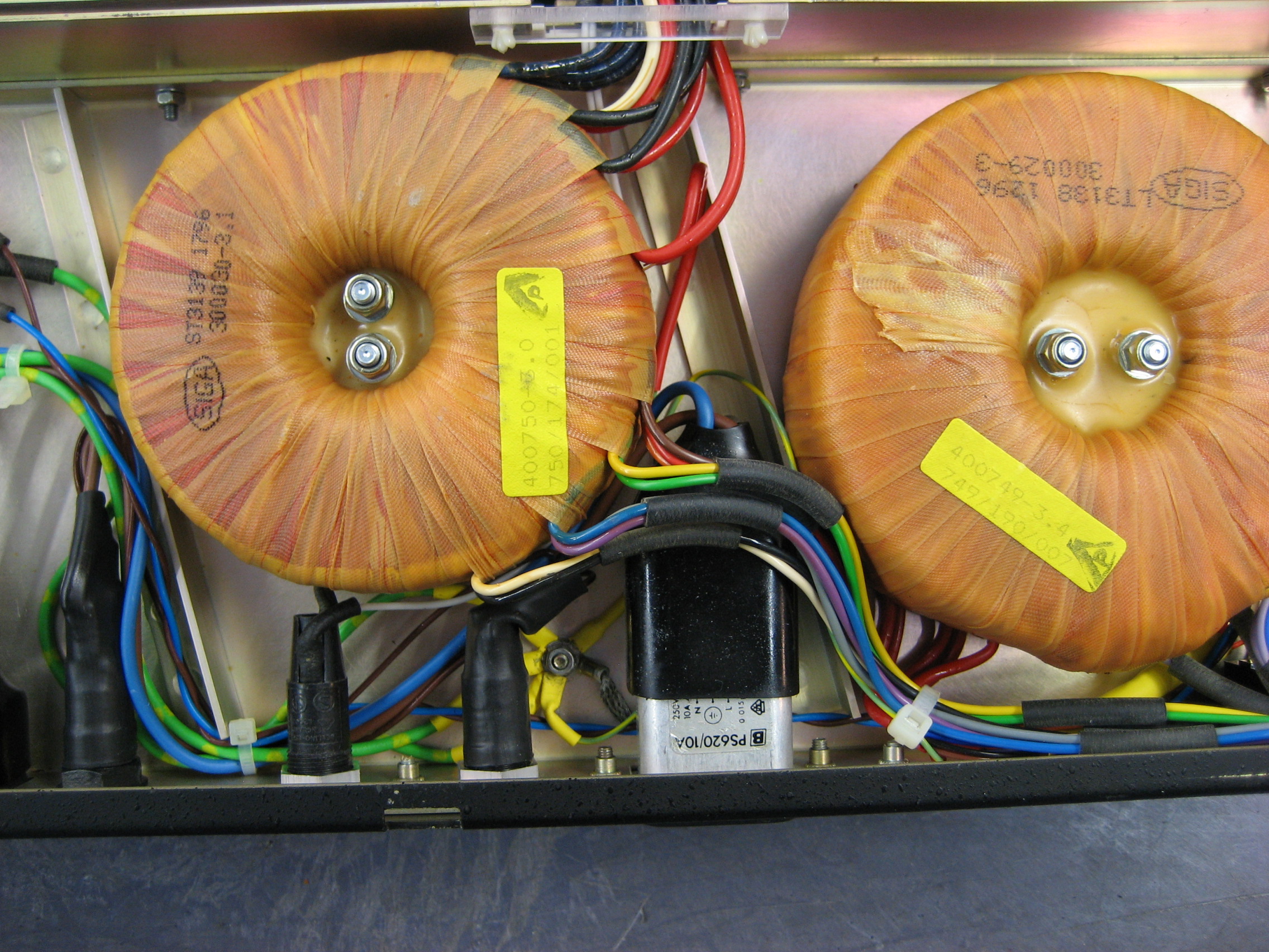
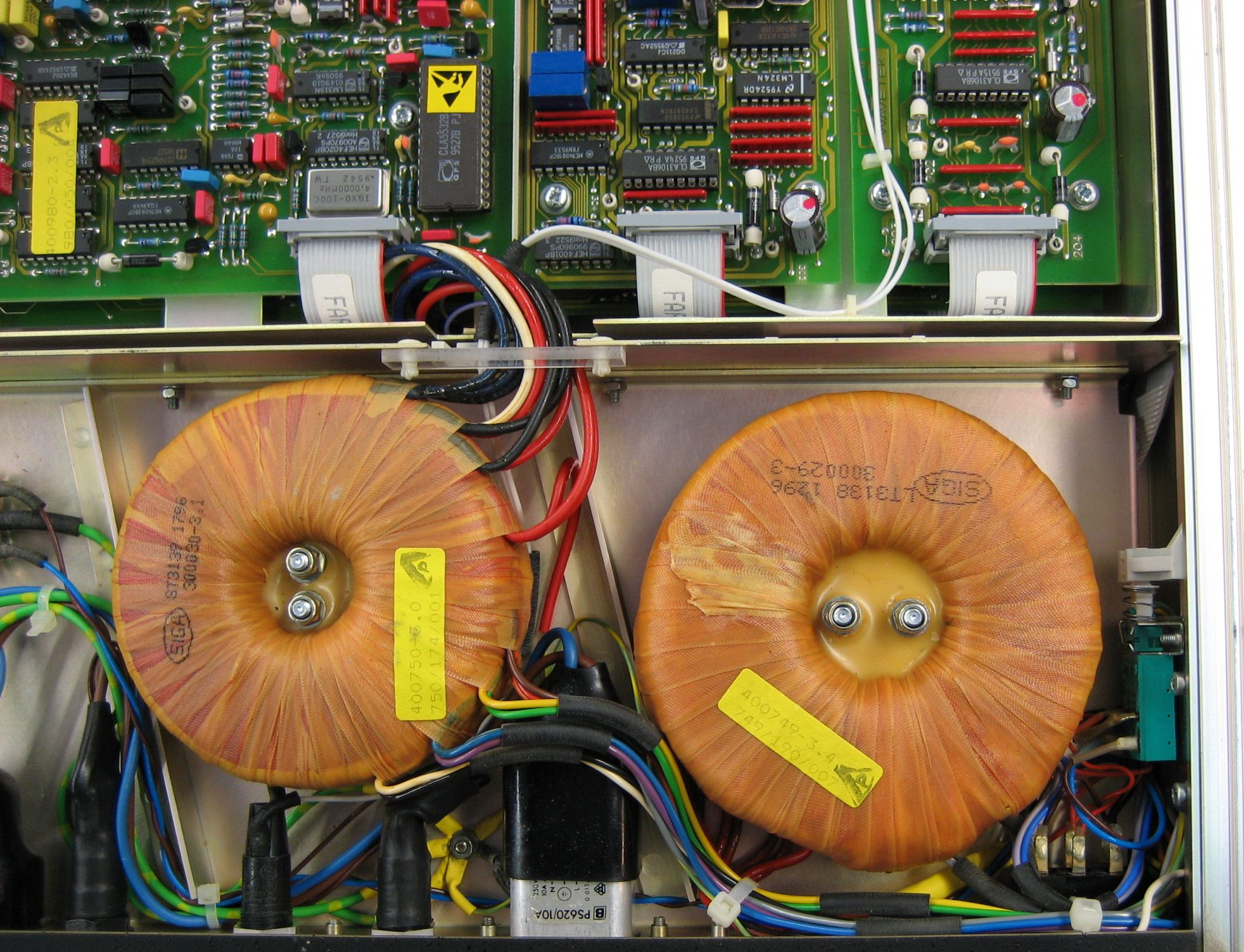
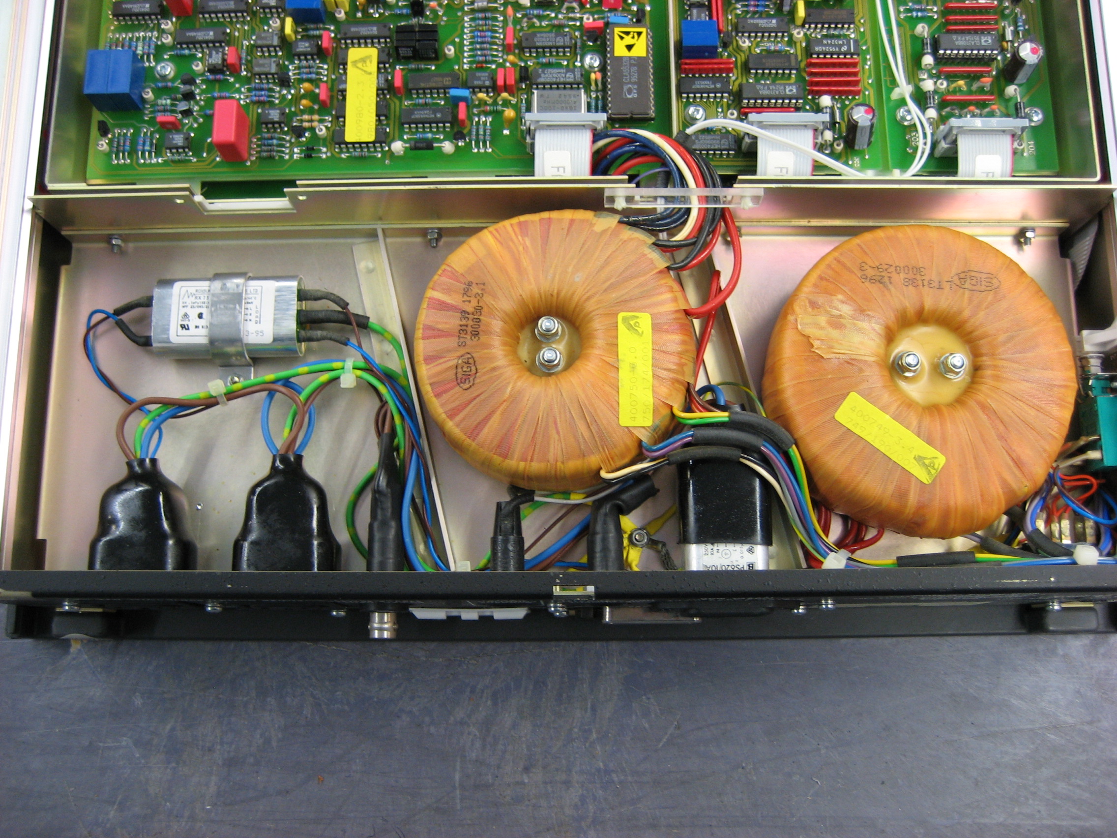

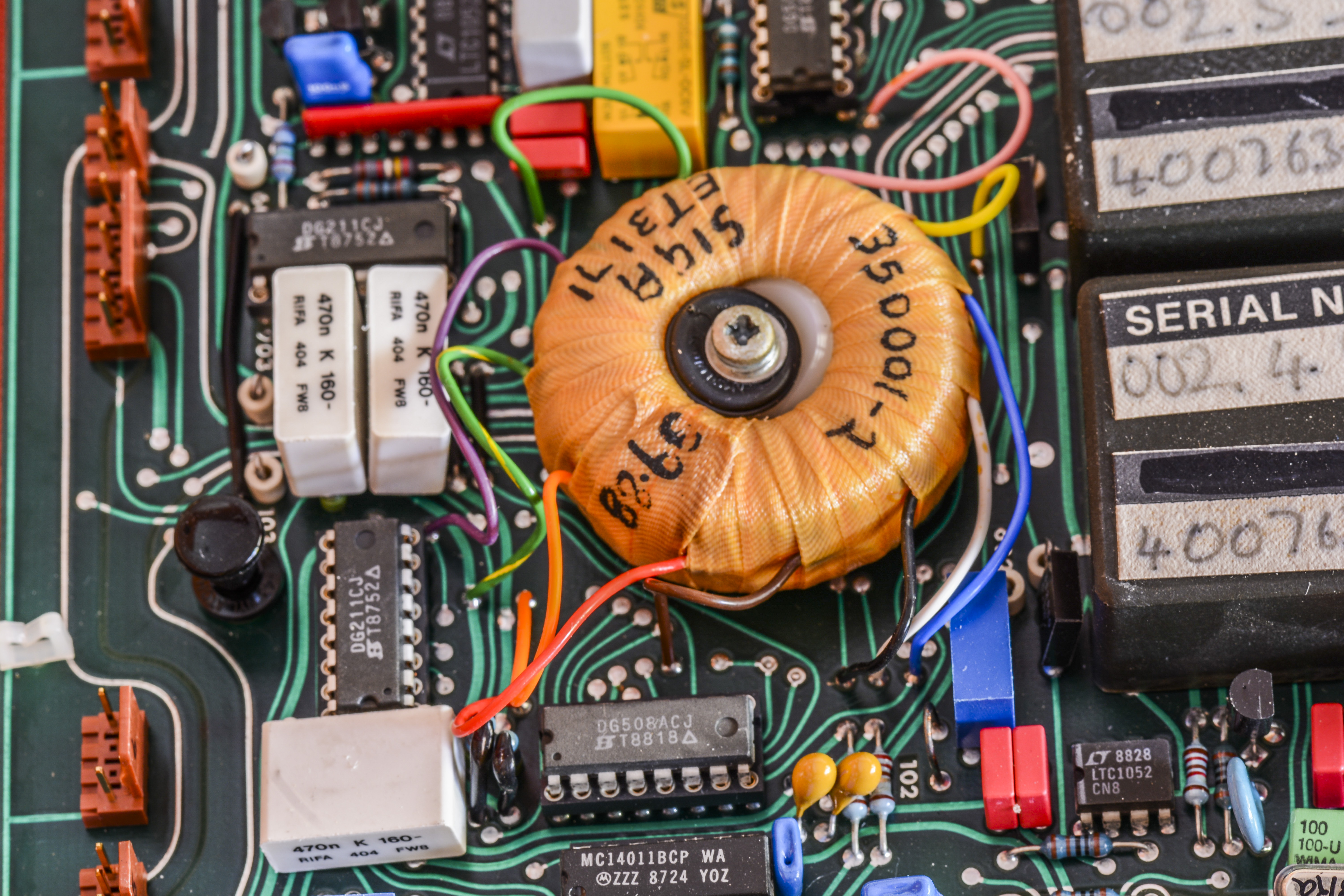
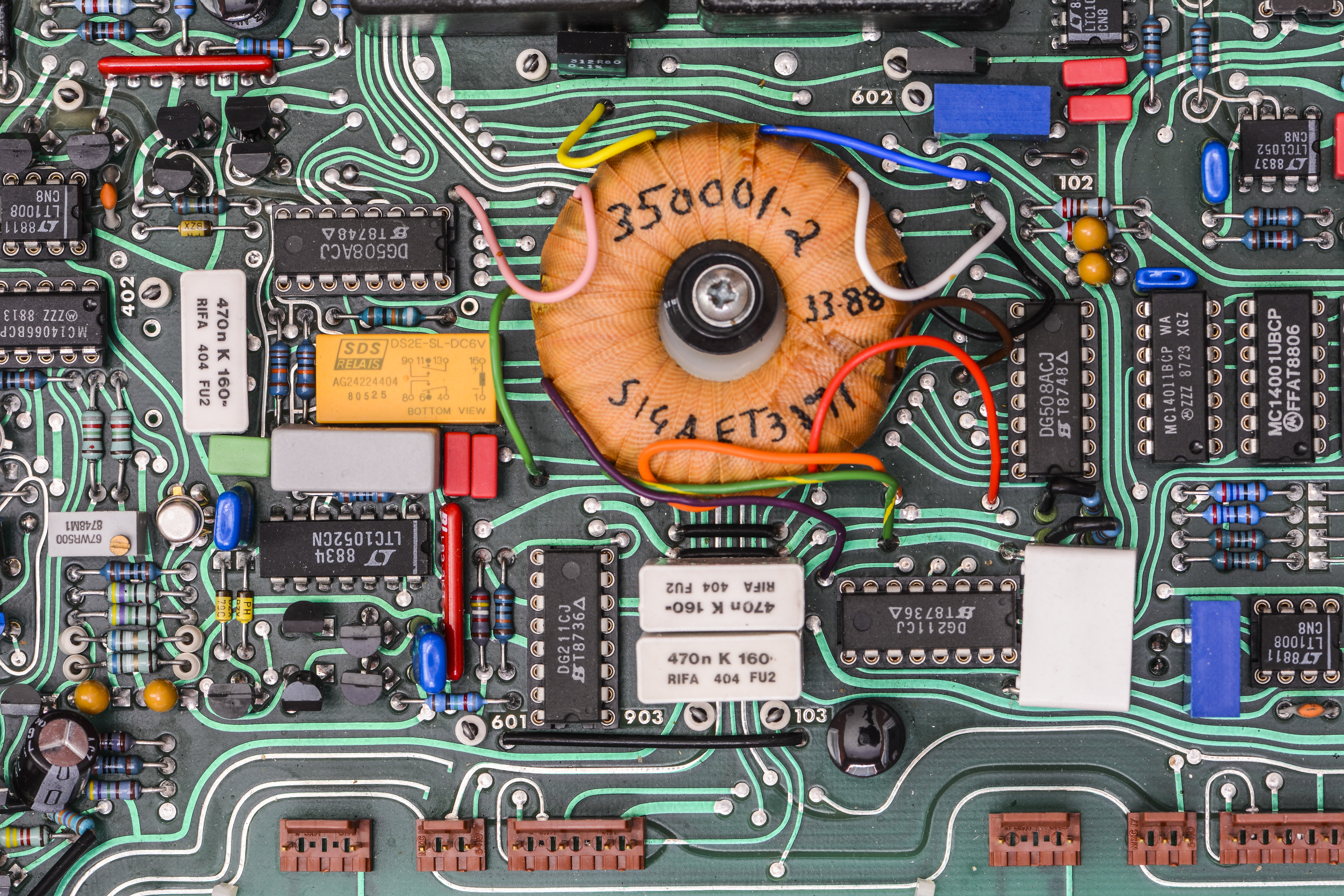
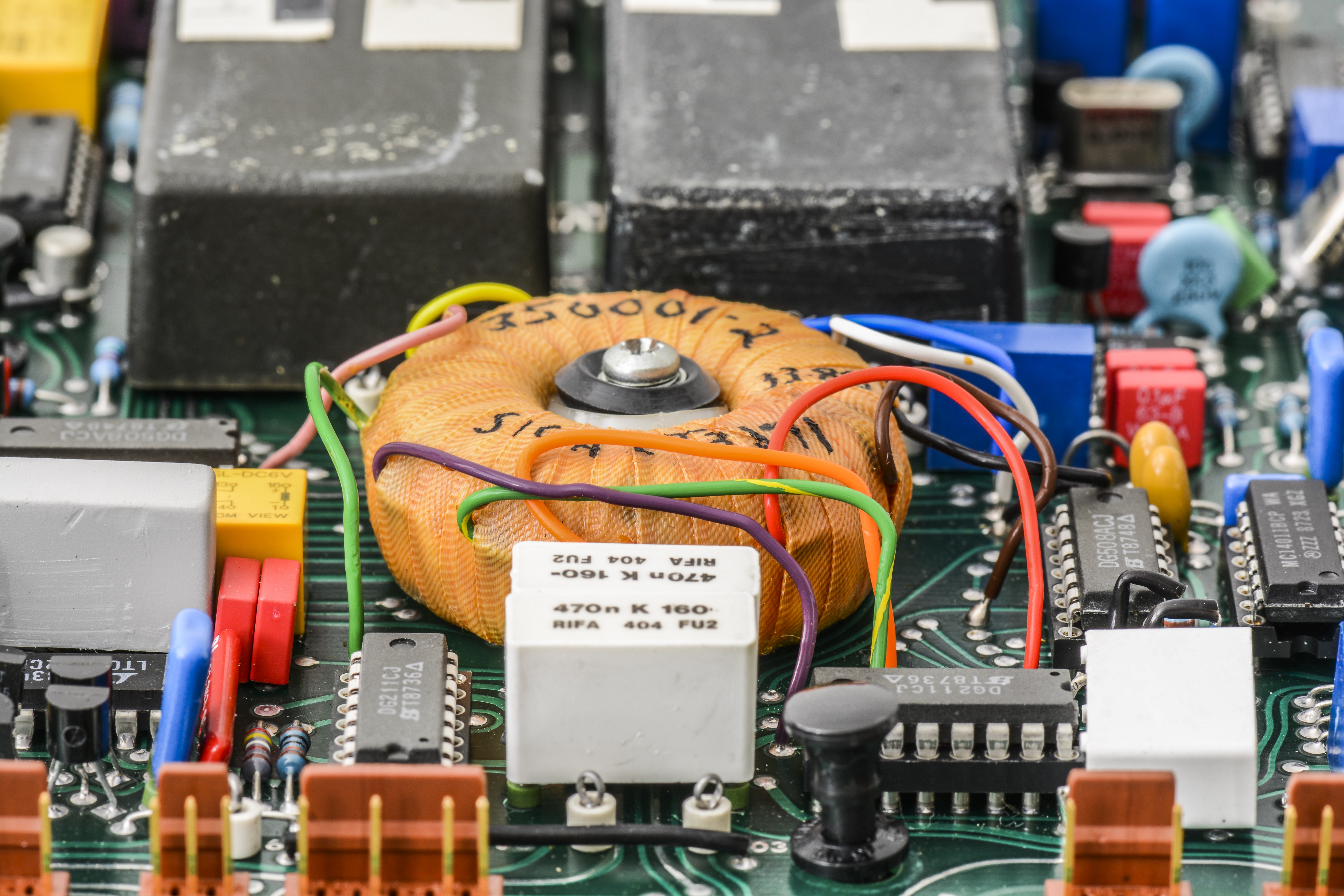
Datron 1281 (and lesser brother 1271) using interesting arrangement for primary power supply with two big toroidal transformers. First transformer converts mains to low voltage supply for earth-referenced digital domain, and powers low-voltage PWM DC-DC around second transformer, with switching frequency in sync with mains.
Secondary outputs of this low voltage transformer are rectified and regulated with usual LDOs to provide clean analog supply voltages. What is the benefit in such double conversion? This design approach targeted to reduce capacitive coupling and keep power consumption by linear power supplies constant, so temperature inside meter’s chassis does not change in different conditions.
We already know, that temperature changes are our main enemy in high precision voltage and current measurements, so Datron had to make extra effort to reduce instability of temperature contributors, instead of adding fans or heat sinks around critical components. Similar idea technology was also used in Fluke’s 7000 DC reference standard and recent Keithley’s 7½-digit DMM7510.
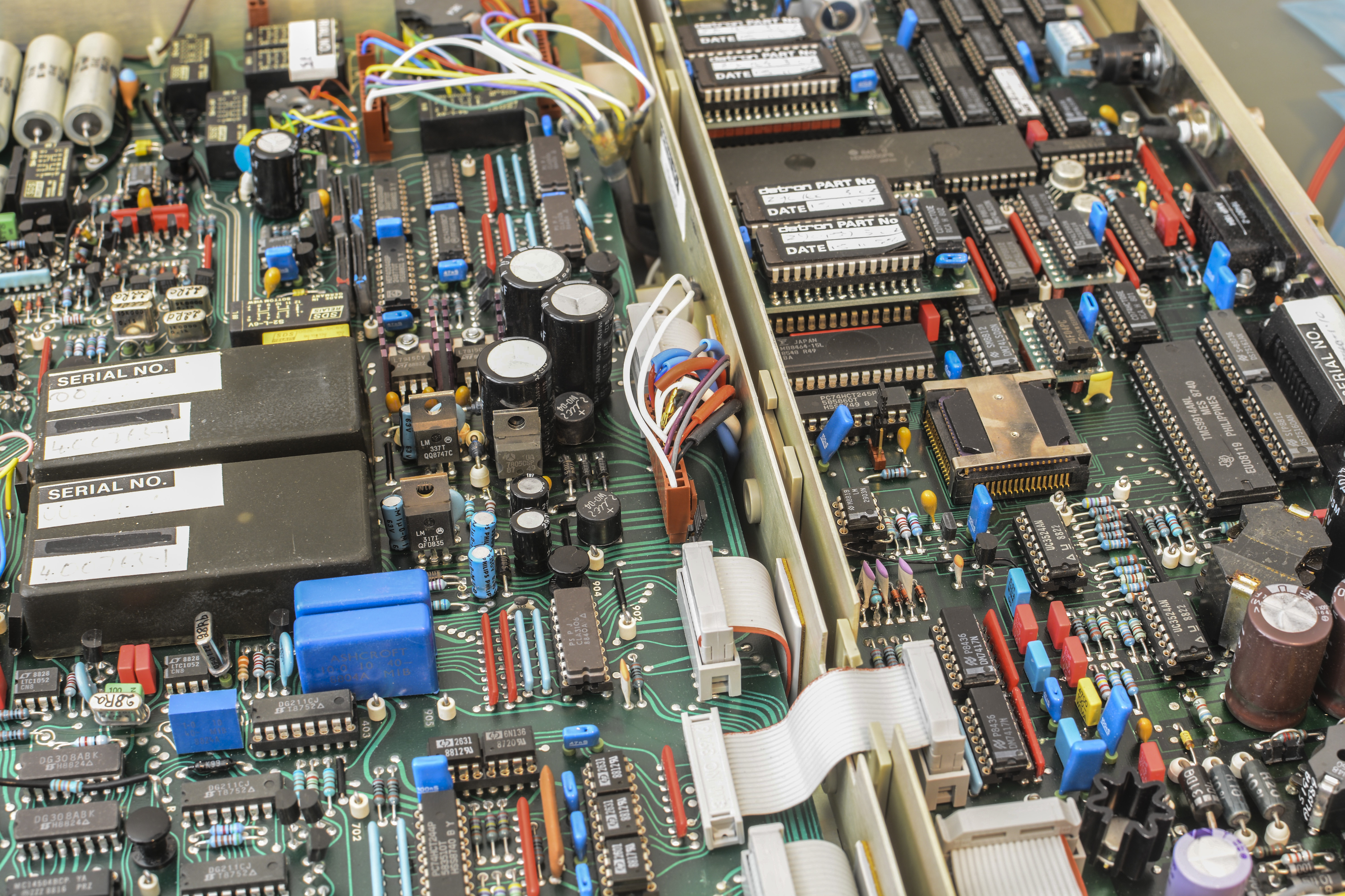
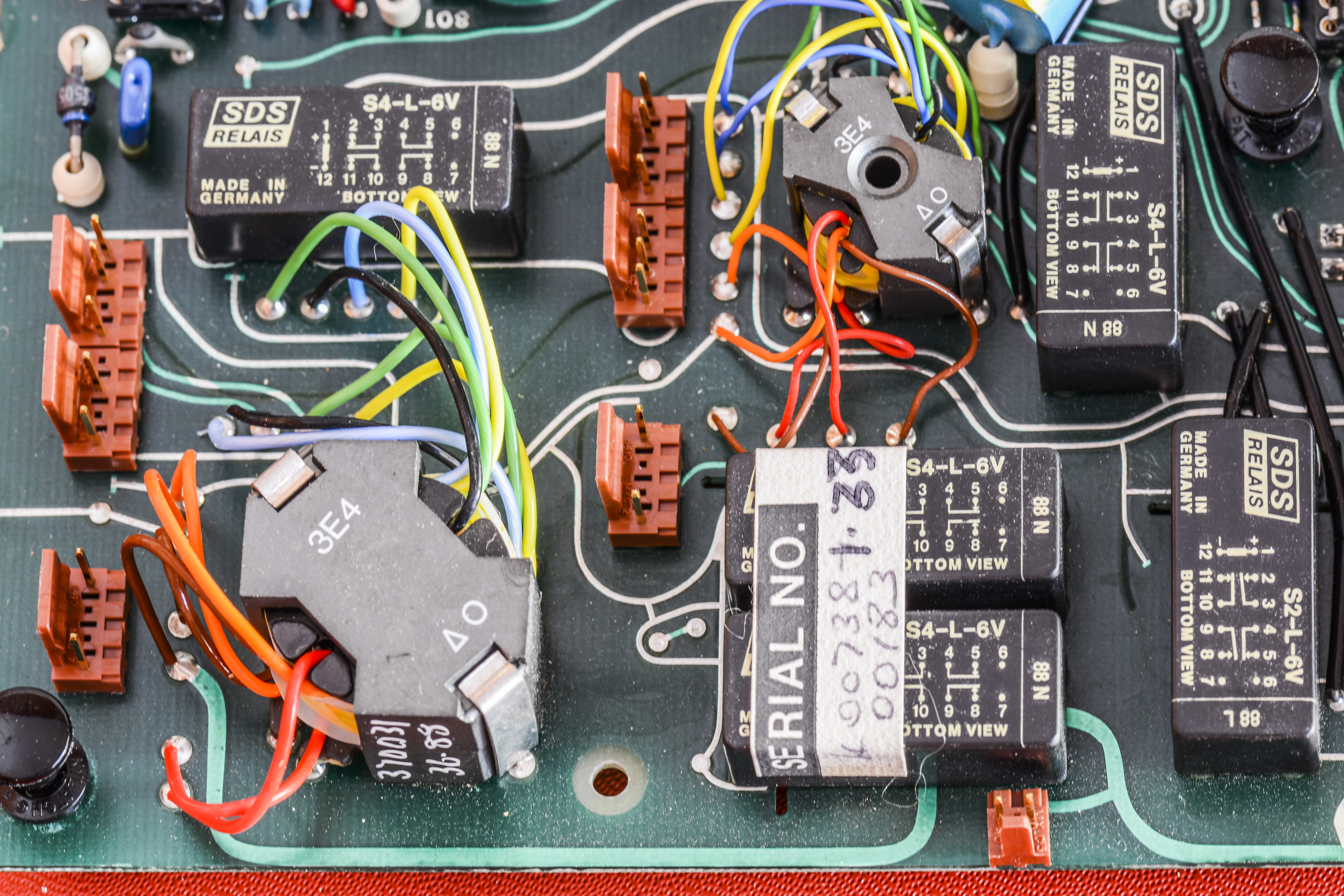
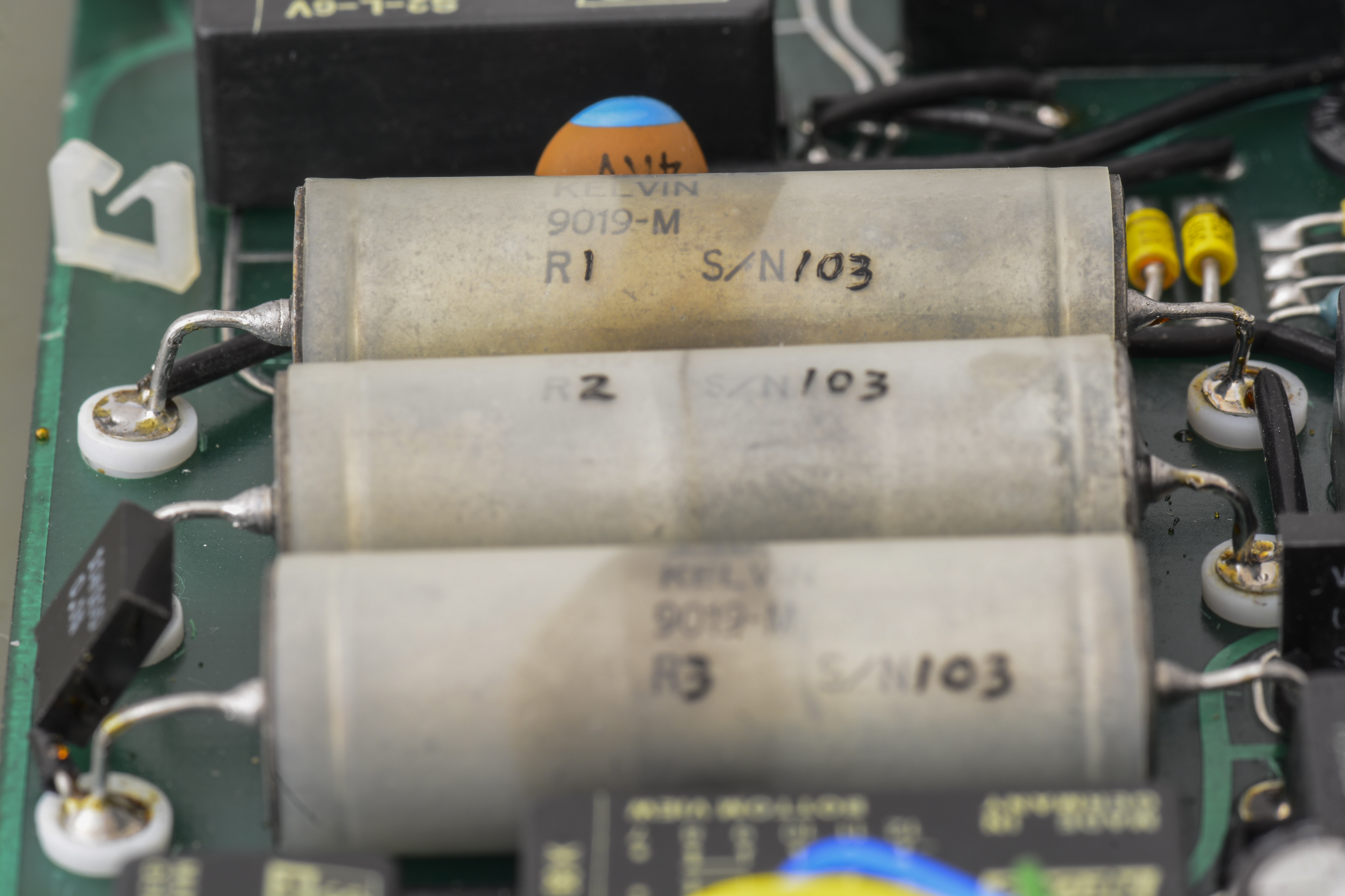
Datron 1281 and 1271 are the using unusual arrangmenet for main voltage reference. Model 1281 using two identical Linear LTZ1000 based modules, labeled Datron 400763-1, with custom hermetically sealed Vishay metal foil resistor network, while Model 1271 using LTZ1000 module and LM399 module to save cost. In out units refereces were enclosed in black epoxy, and would be troublesome to remove from PCB for teardown.


Ehile testing optocouplers with second Datron 1281, it was noticed that error codes were different on second meter if optocouplers were left out of circuit. Possibly one of the daughterboards was failing? A quick check of all cables to the main DC board showed one that was not connected and stuffed under the main board. Not good, as this shows someone was diagnosing an issue that required the board to be possibly removed from the frame.
After reconnection cable, this 9005 error code went away and first DCV readings were acquired. It looked good with the input shorted, however the OHMs readings were open. Another search for connector issues showed the input connector was hastily plugged in and had missed a pin on the DC board, pushing it aside. A quick reconnection and all the ranges appeared to respond as expected with the short on the input. A screw was also missing that held the connector in place.
A quick self-test gave what probably were the original errors, DCV ERROR 2182 DC 100mV range zero magnitude and NVRAM error. The errors are broken down based on the type of test. The Fast test failure code is explained in section 2.7.3 for True Zero Checks. It tests the mean value with the inputs shorted on the 100mV range.
Conditions are for test 2182 are : -250µV < Mean 100mV Zero < +250µV.
The NVRAM error is most likely due to a bad old battery, similar to what we already know from repairing old instruments like HP 3458A, scope CSA7404 and R&S SMT03. Good rule of thumb is to replace all batteries if instrument is older than 10 years.
Without further diagnosing of the error, the inguard and outguard supplies needed to be tested as the parts have datecodes from 1988 and the lithium backup battery is dated from 1987. Its voltage was measured at 3.7V which is pretty good for a nearly 30yr old battery.
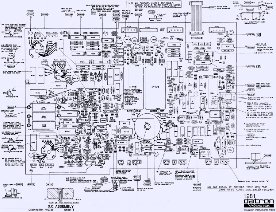
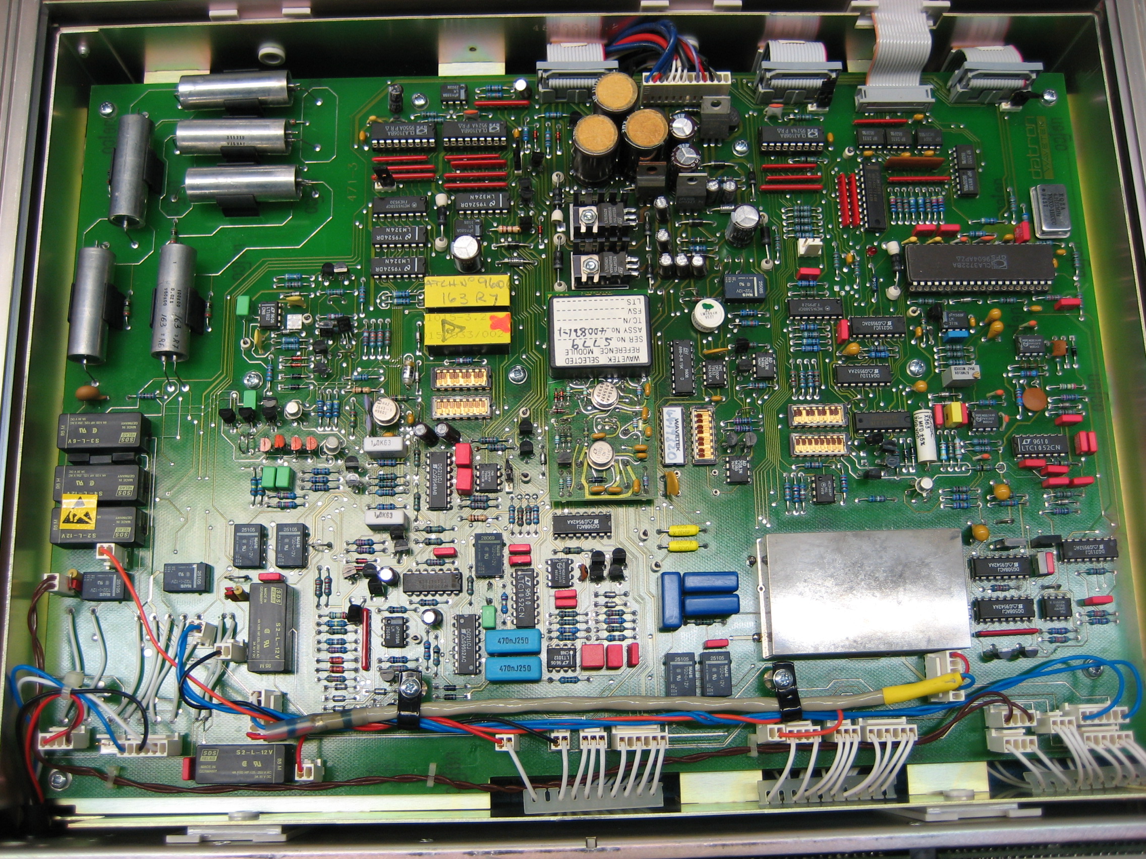
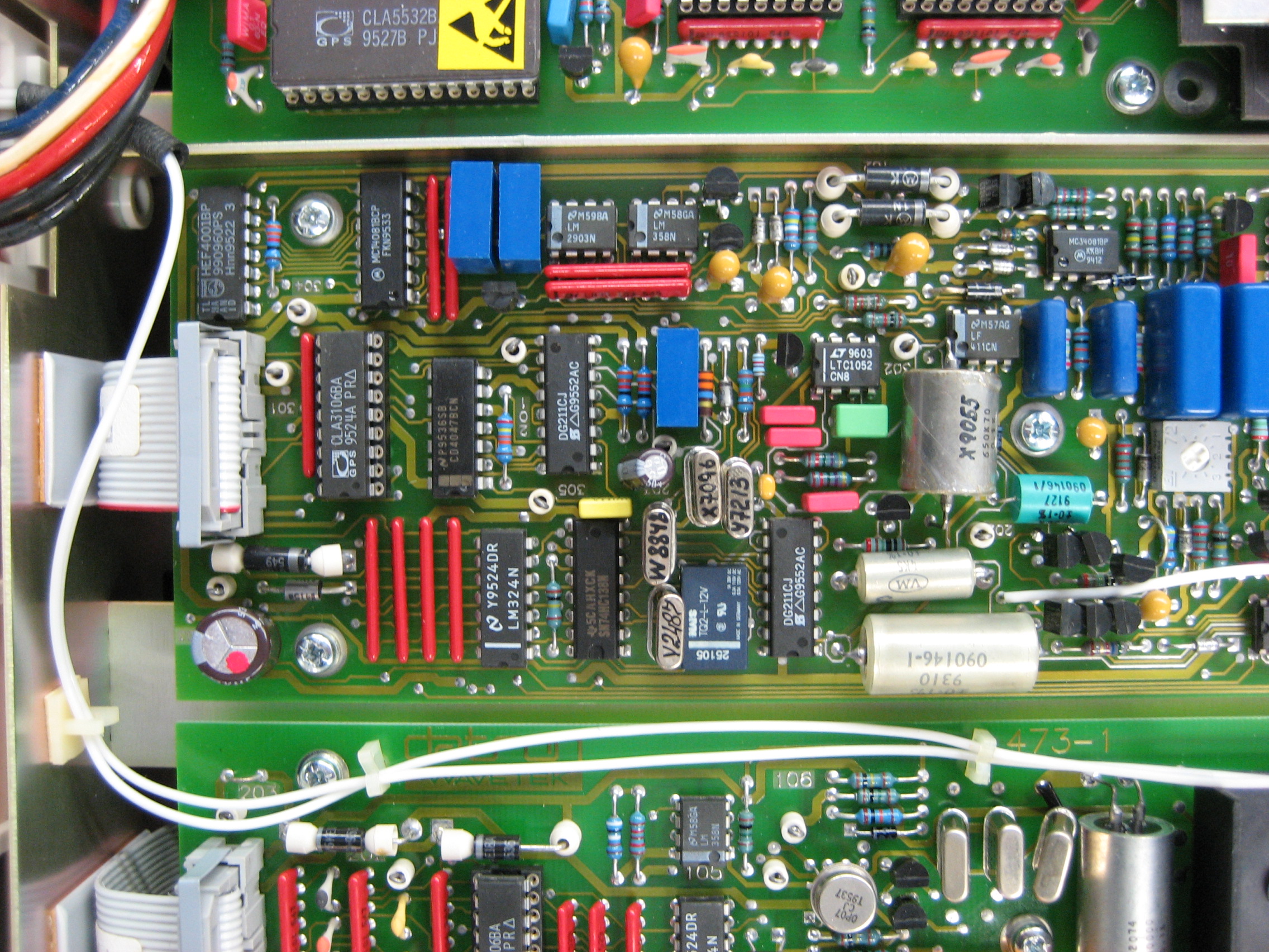
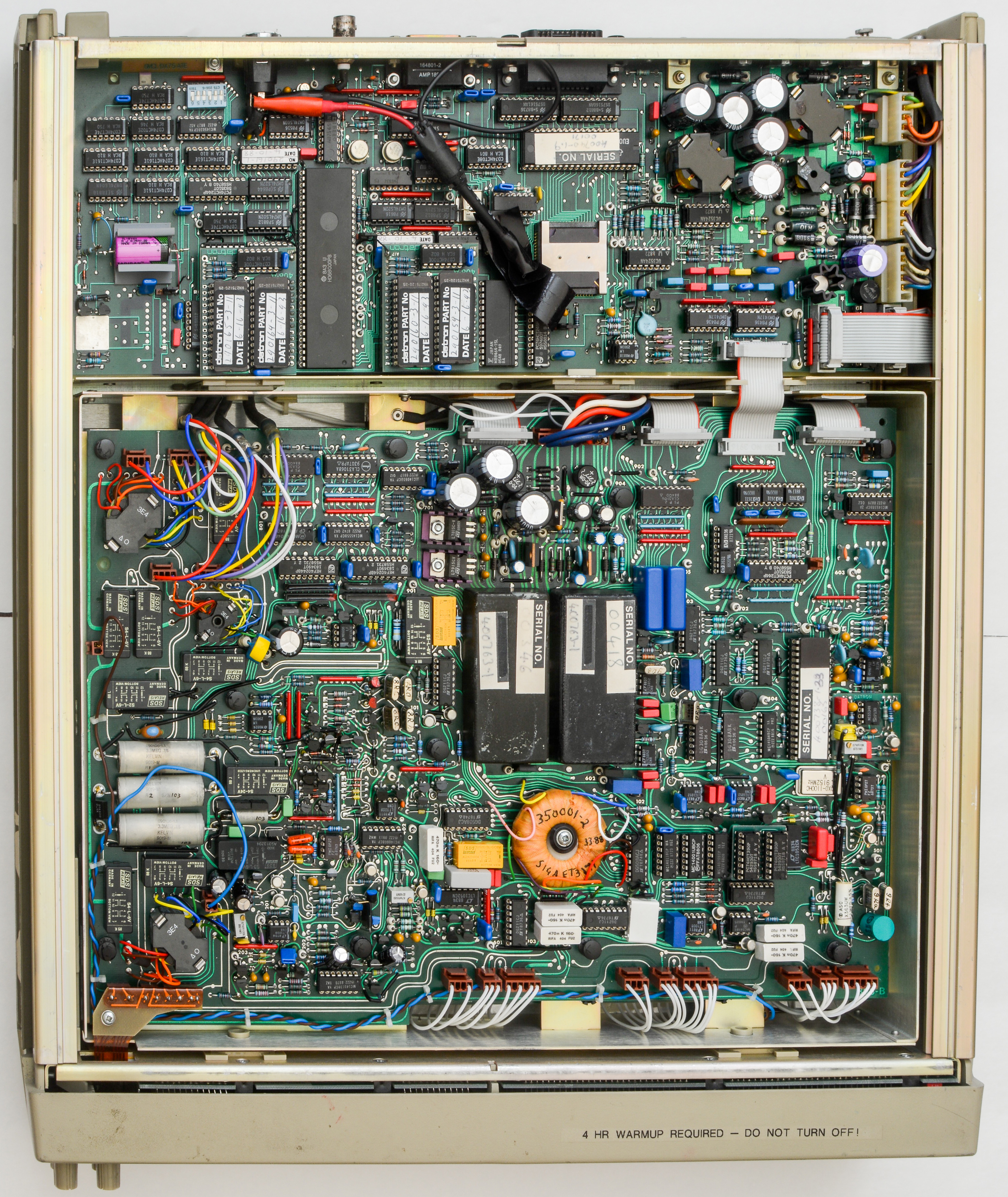
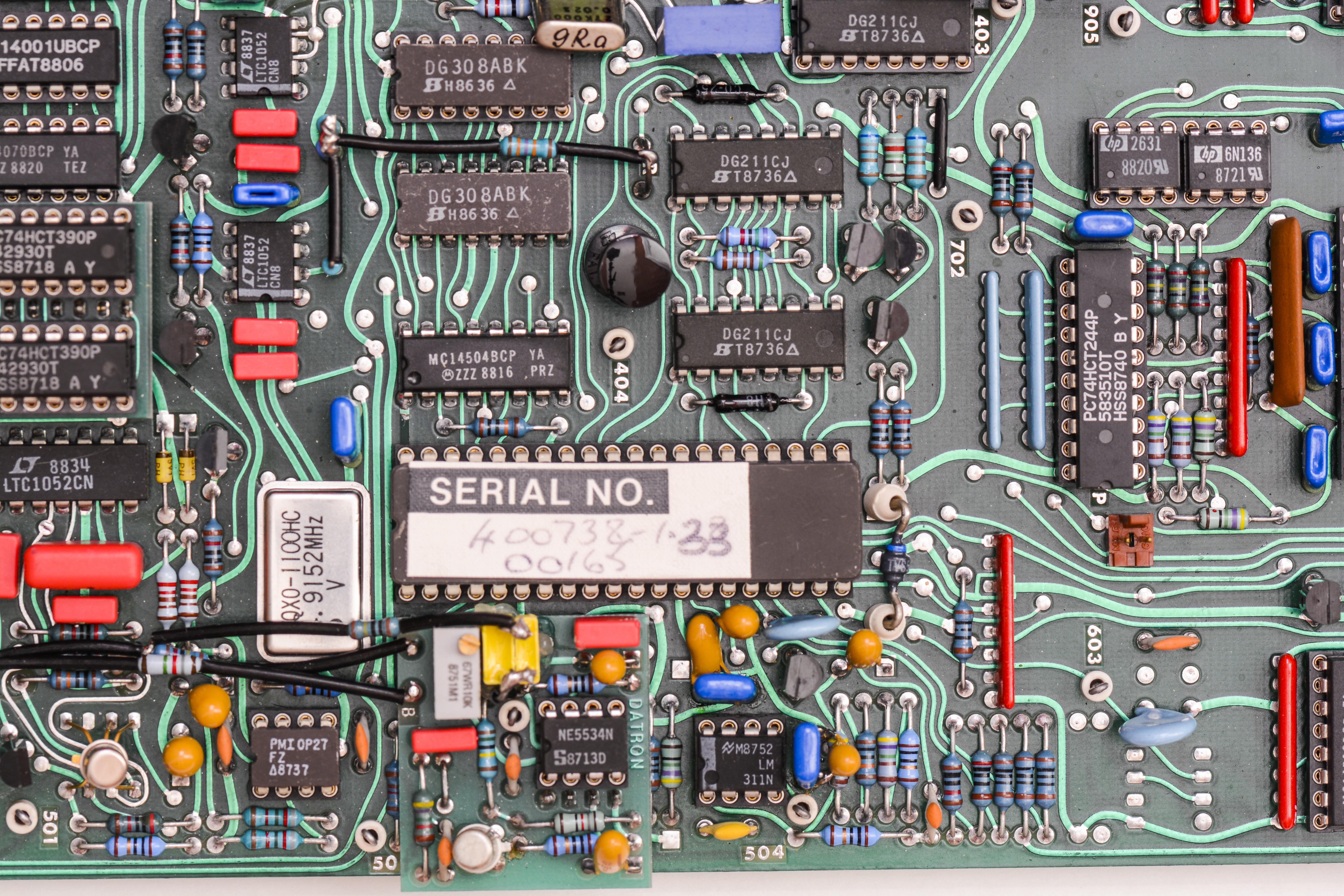
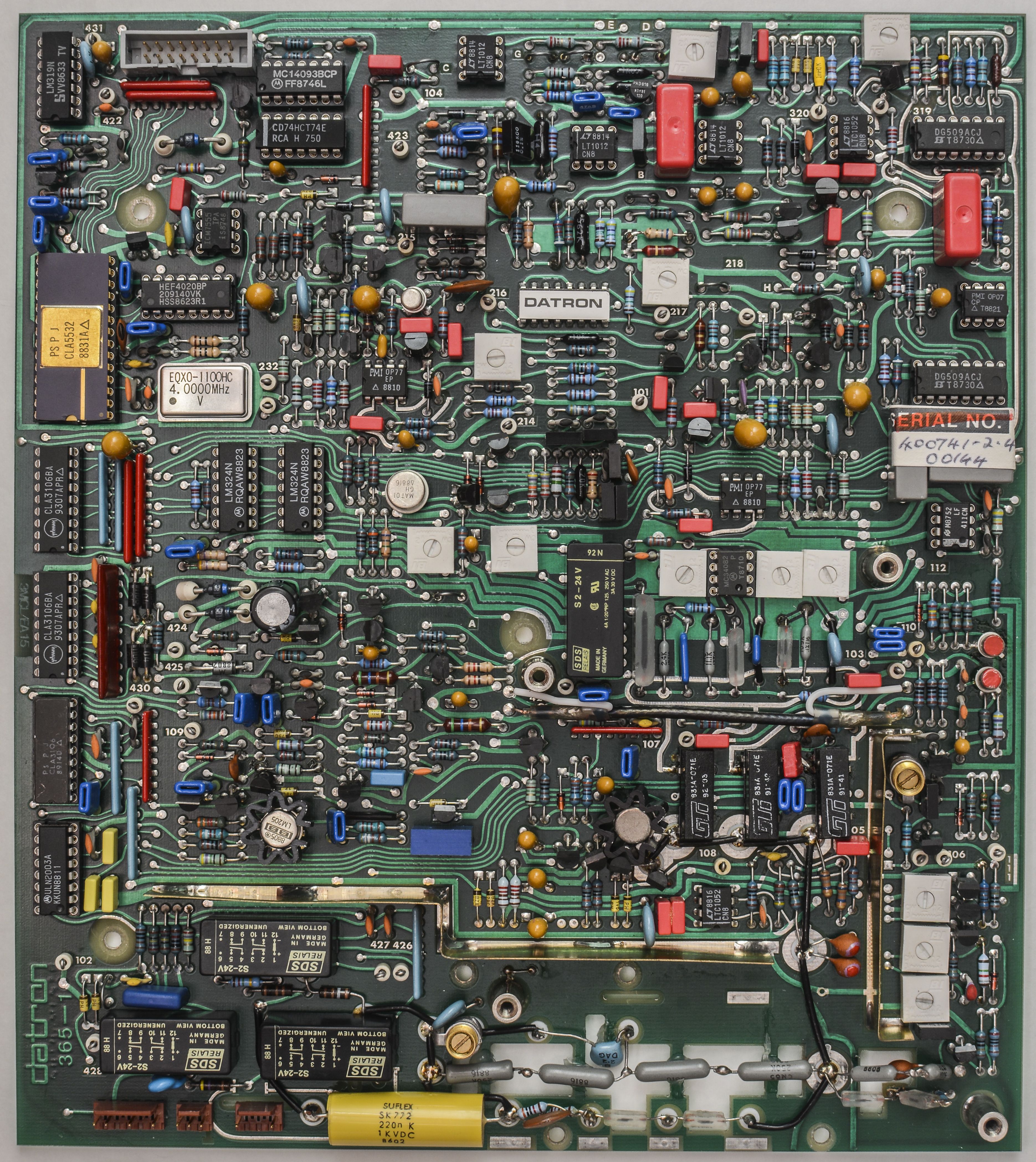
The schematics for both the inguard and outguard supplies were scanned. Test points for the DC board were easily found as Datron did not use silkscreening on their boards and used unmasked copper for the TP numbers on the DC board. The Digital board, however, has no markings and does not match the component layout drawing in the service manual.
Neither boards have any REV markings on the top, but might be located on the bottom side.
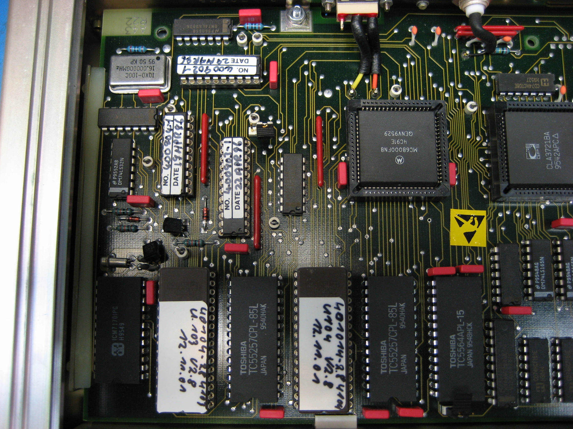
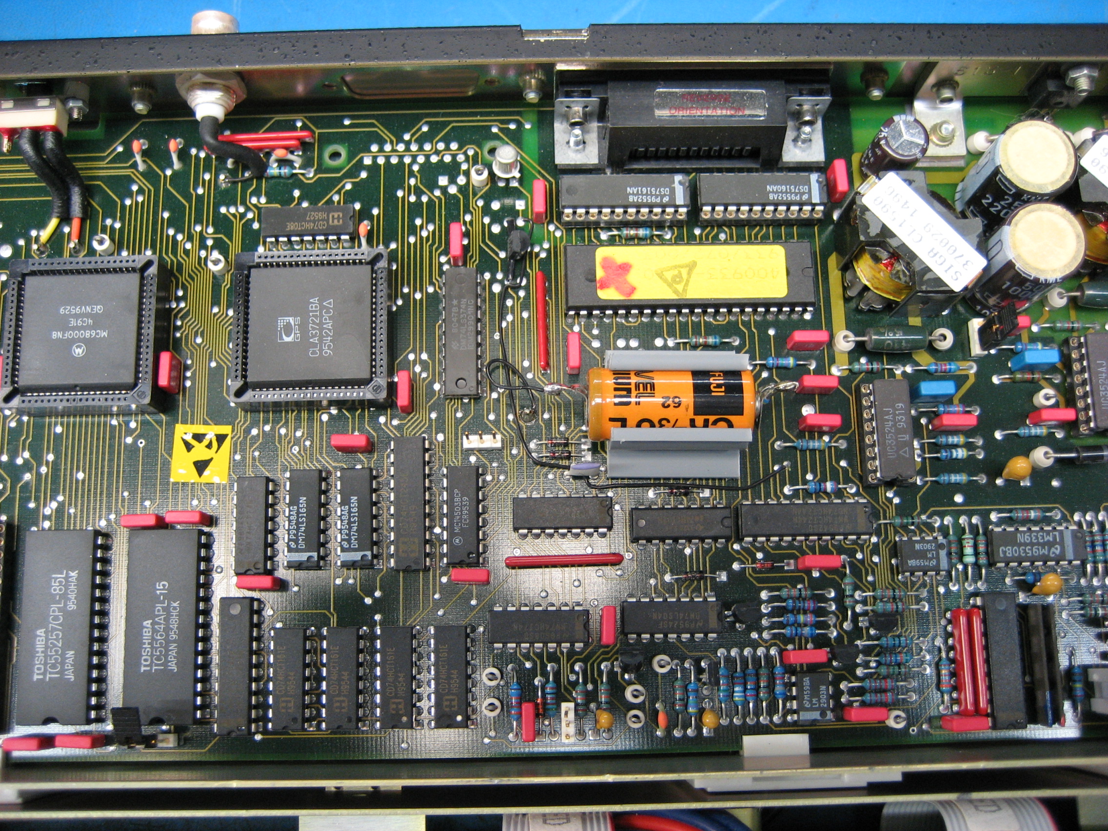
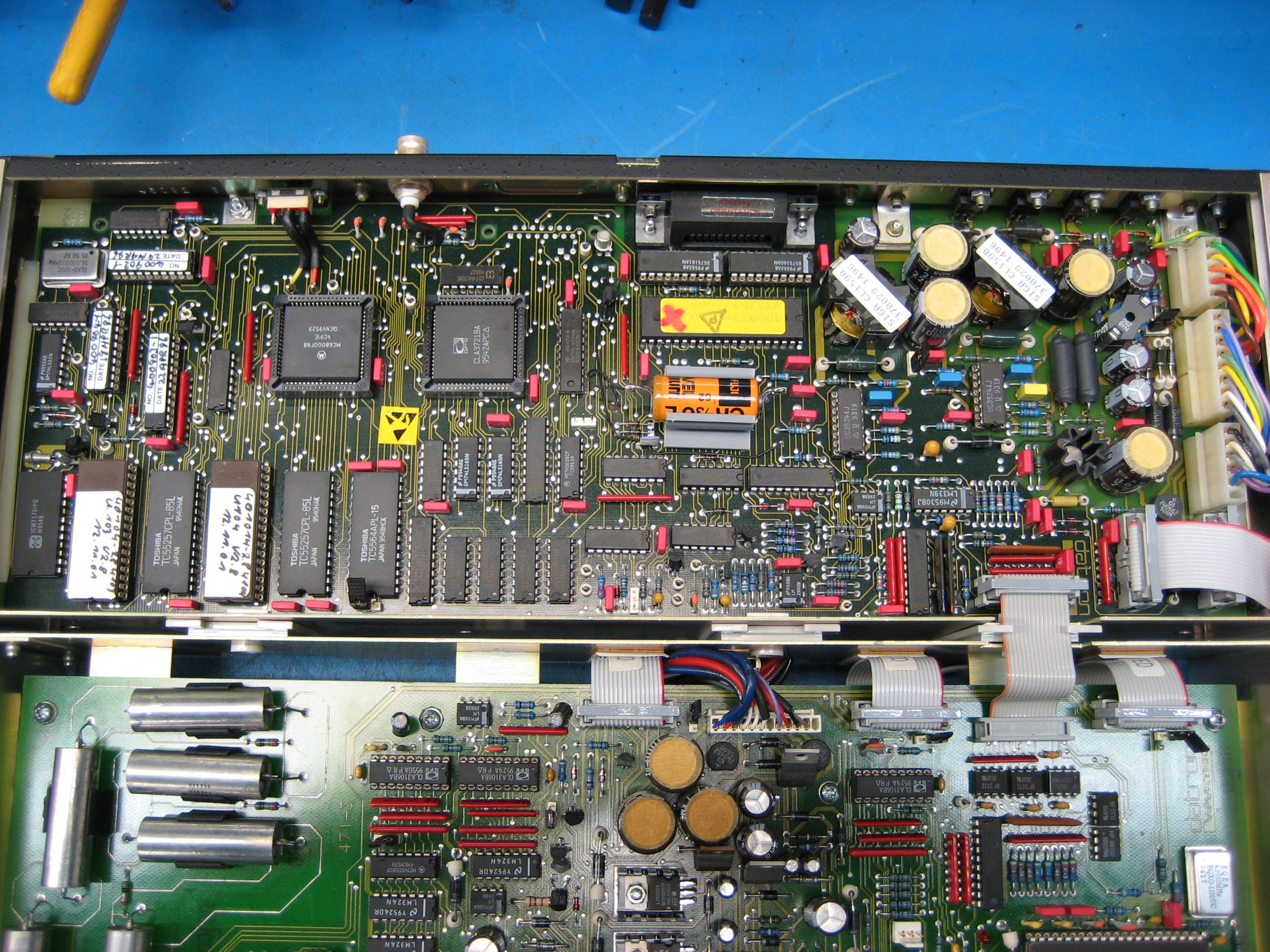
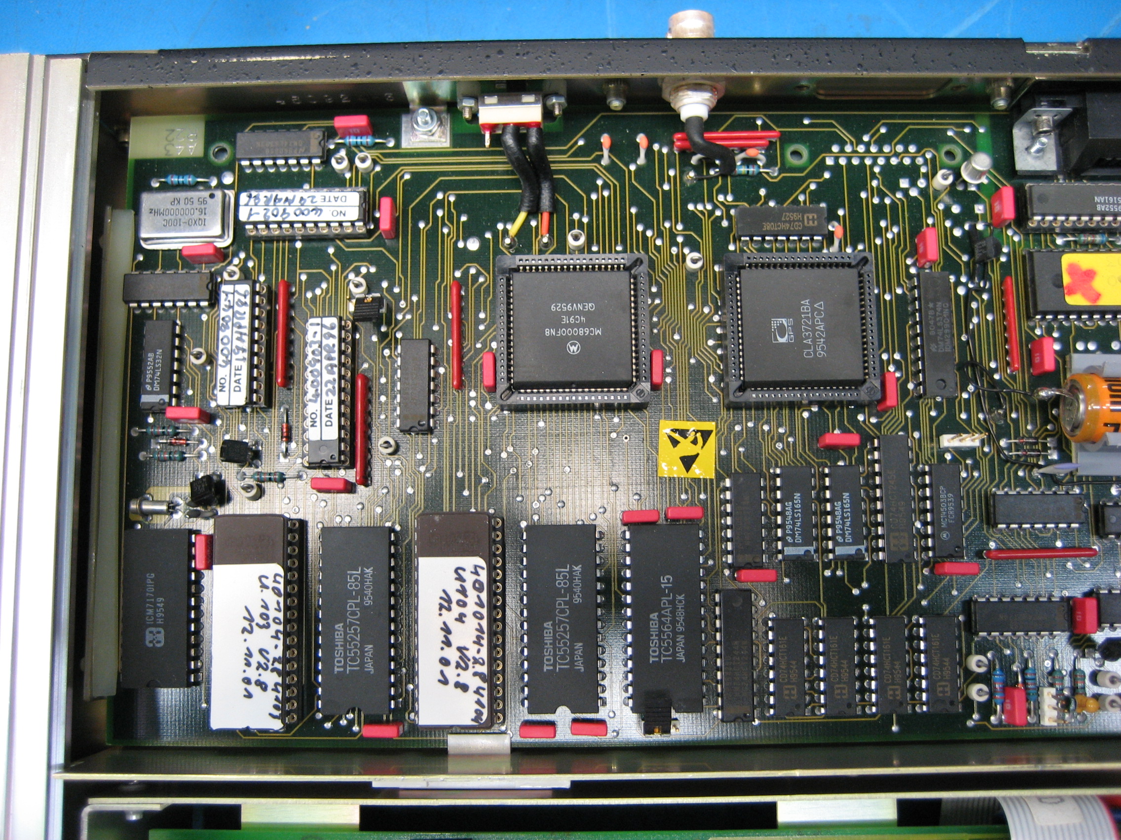
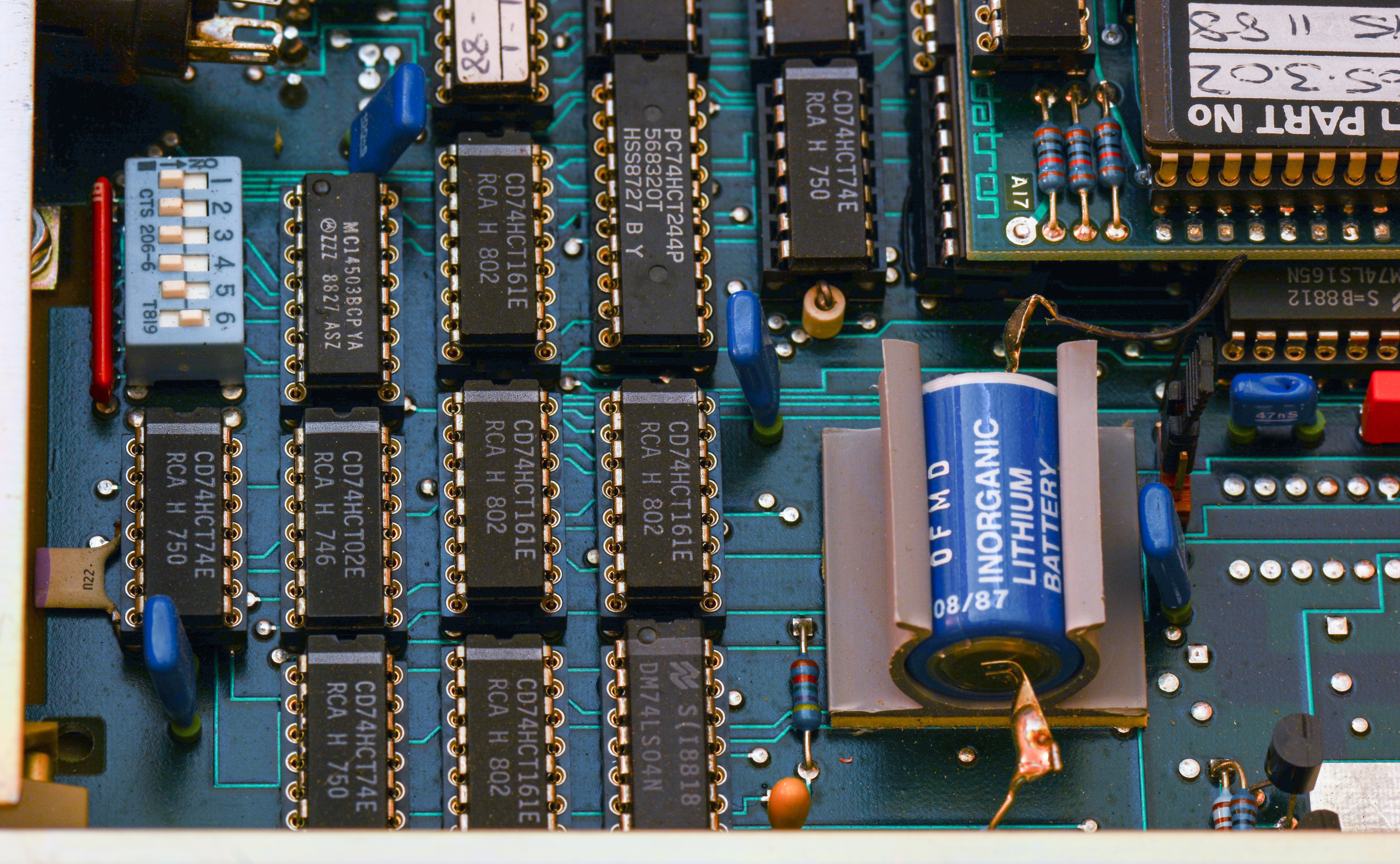
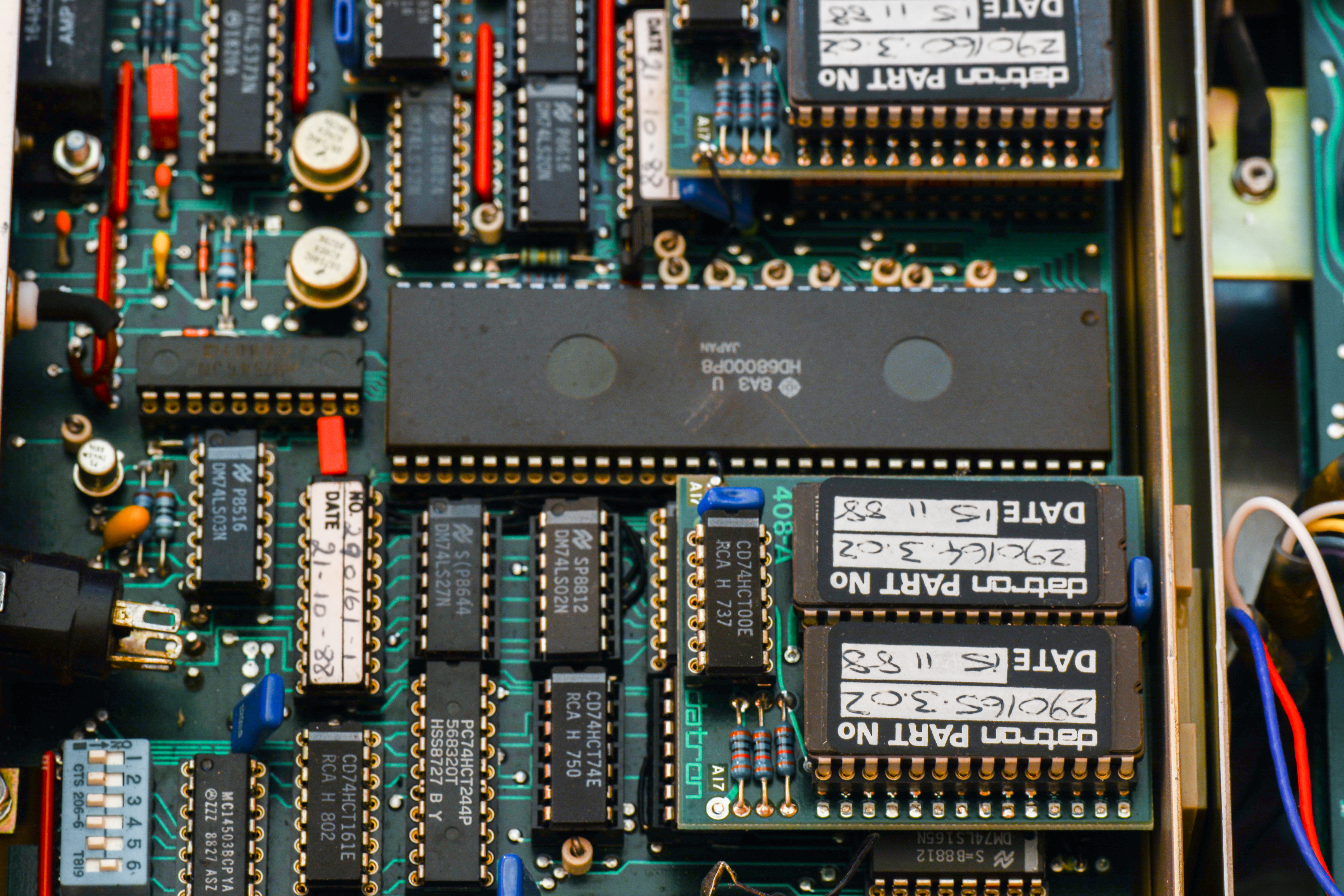
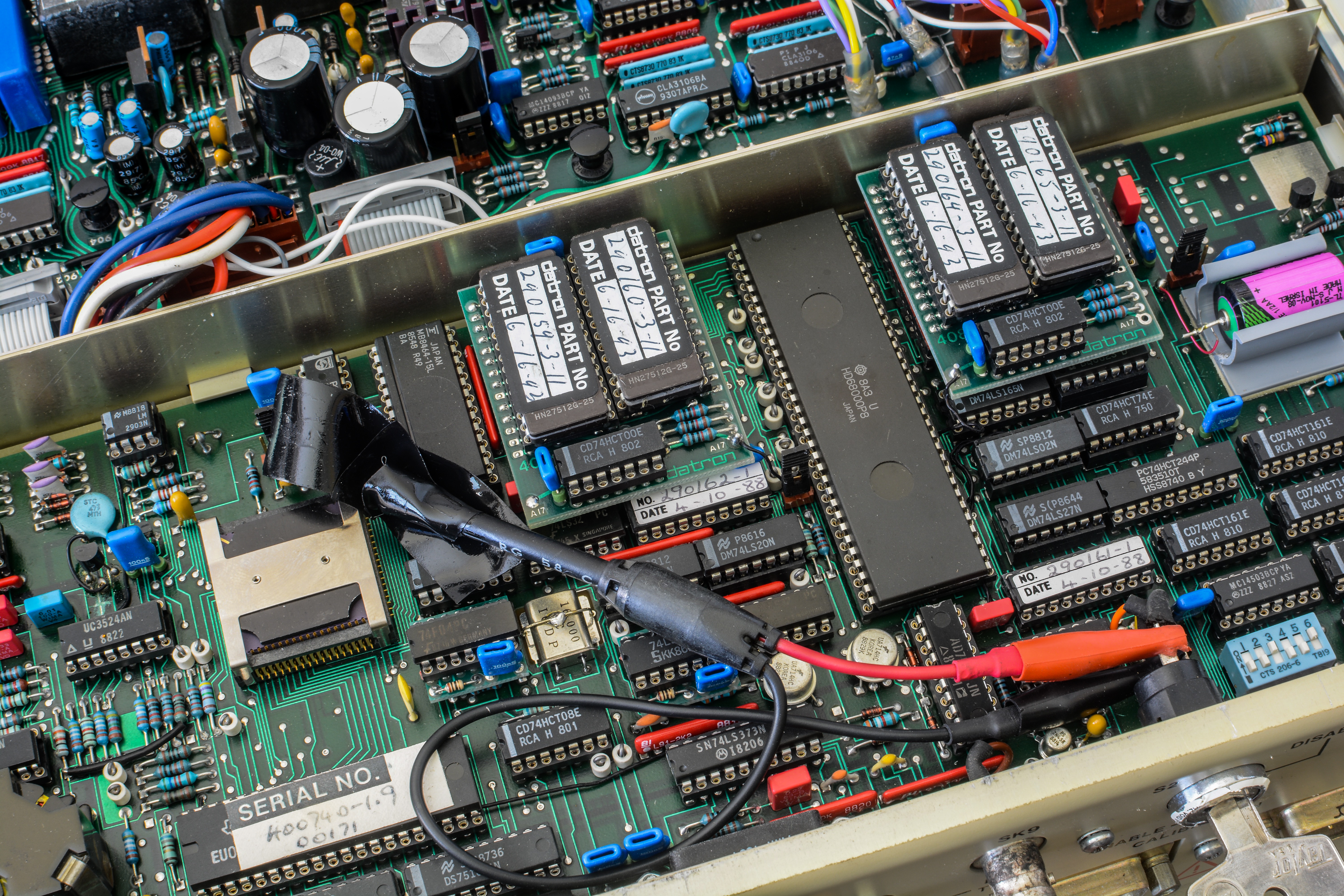
Digital board
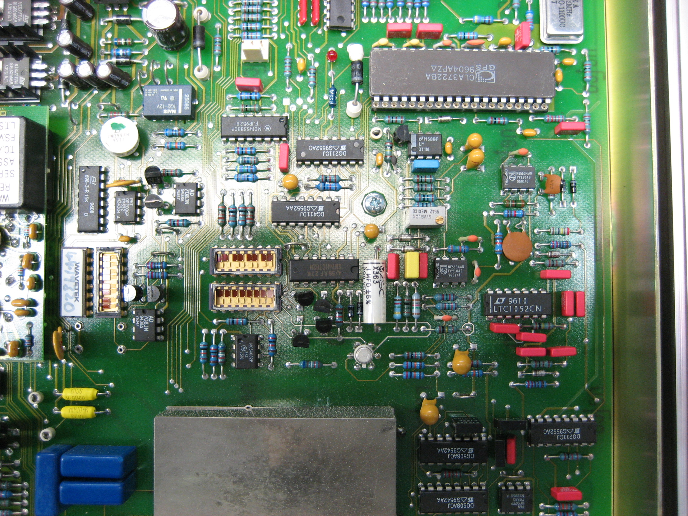
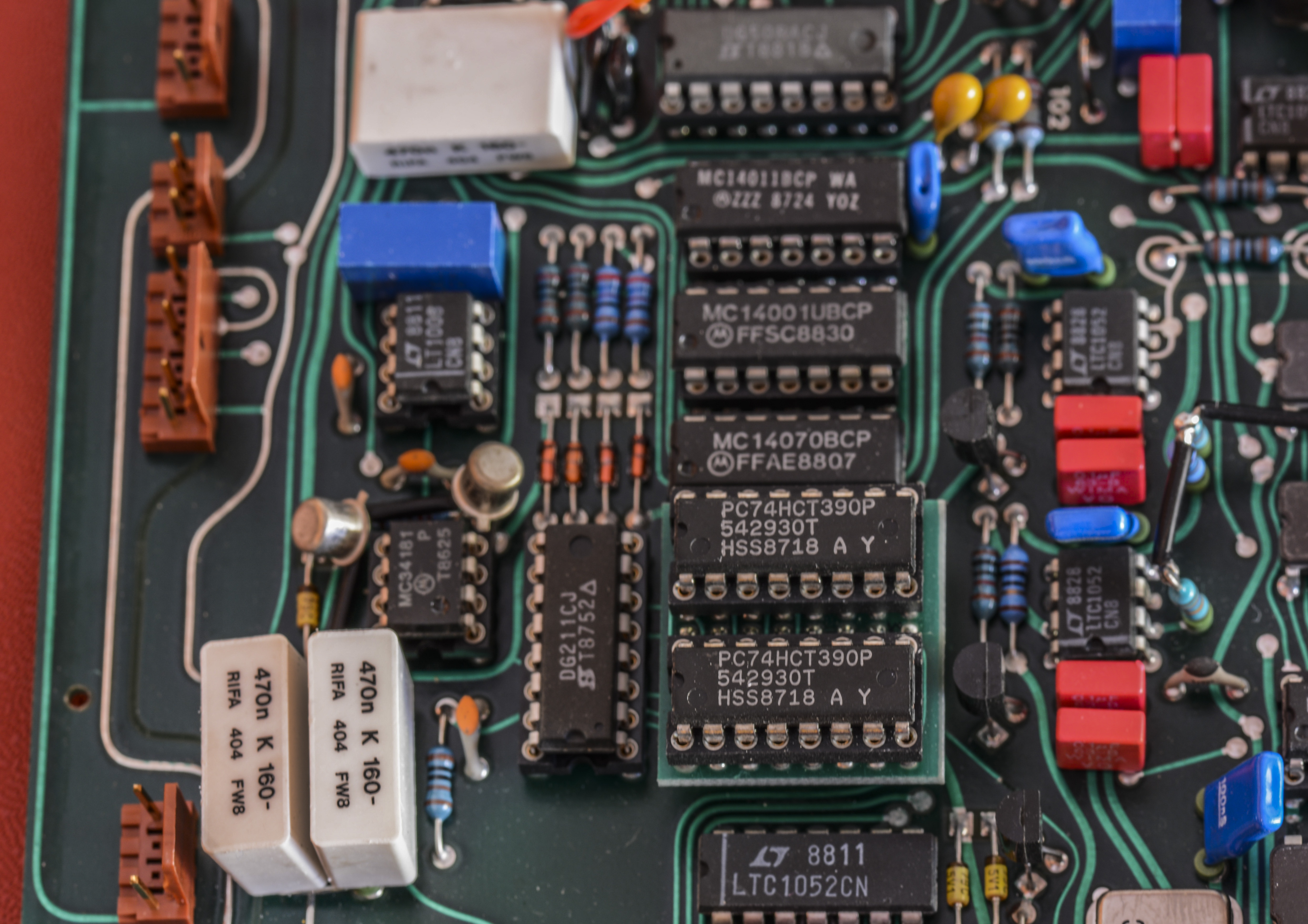
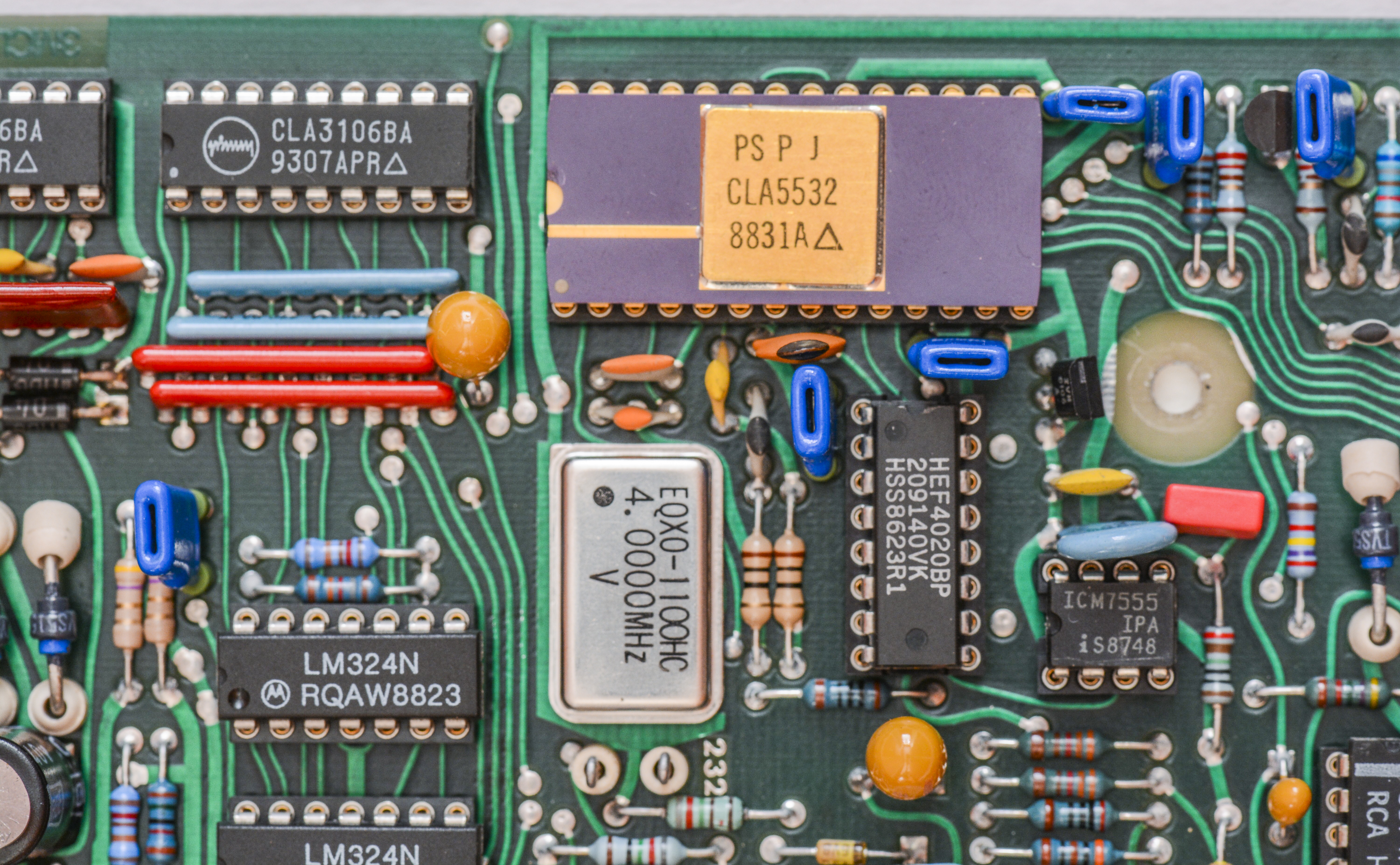
This PCBA have main meter’s brain, good old 16 bit Motorola HD68000P8 processor, manufactured by Hitachi. It’s indeed very popular chip, present in many instruments of those years, such as HP 3458A, Keithley 200x, etc. It is NMOS based 5V ASIC, specified to run at 8.0 MHz clock and able to address 16 MBytes of memory space.
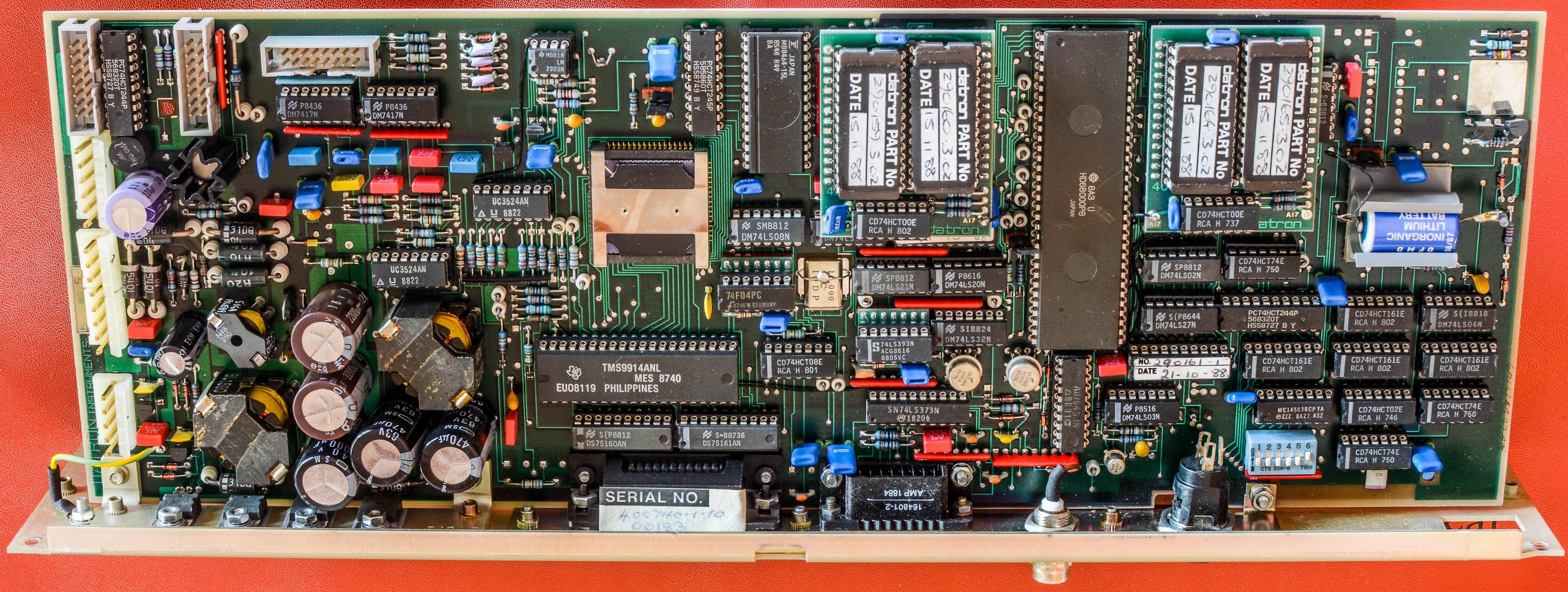

There are multiple different versions of this PCBA for Datron 1281. Another kind of board is shown below:
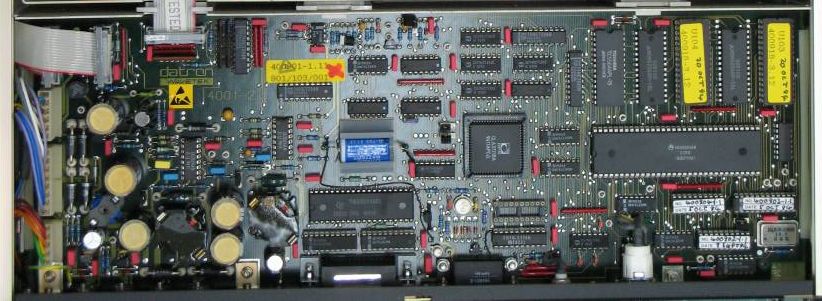
%(imgref)Image X: Digital board, courtesy of www.amplifier.cd
Lot of 7400 series logic can be found around processor, having glue function for various I/O interfaces and control signals. All DIP-packaged ICs are replaceable, with using nice collet-type sockets. Re-seating all chips would be a good idea, considering age of the instrument and unknown history.
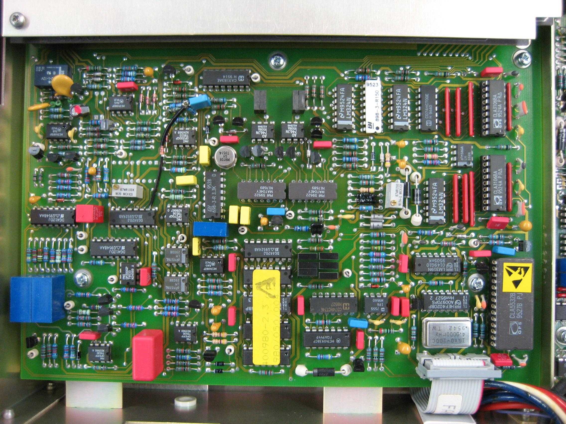
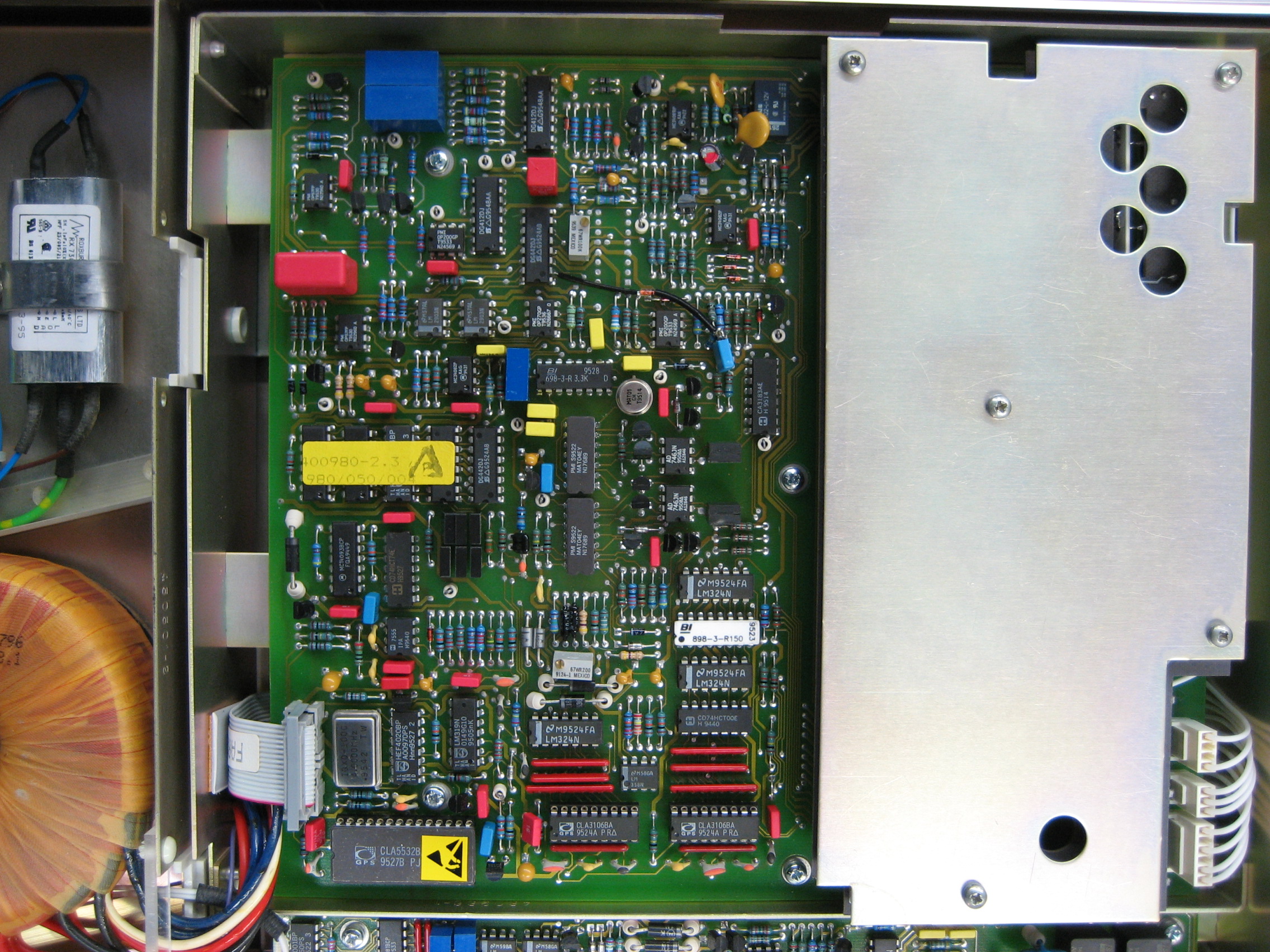
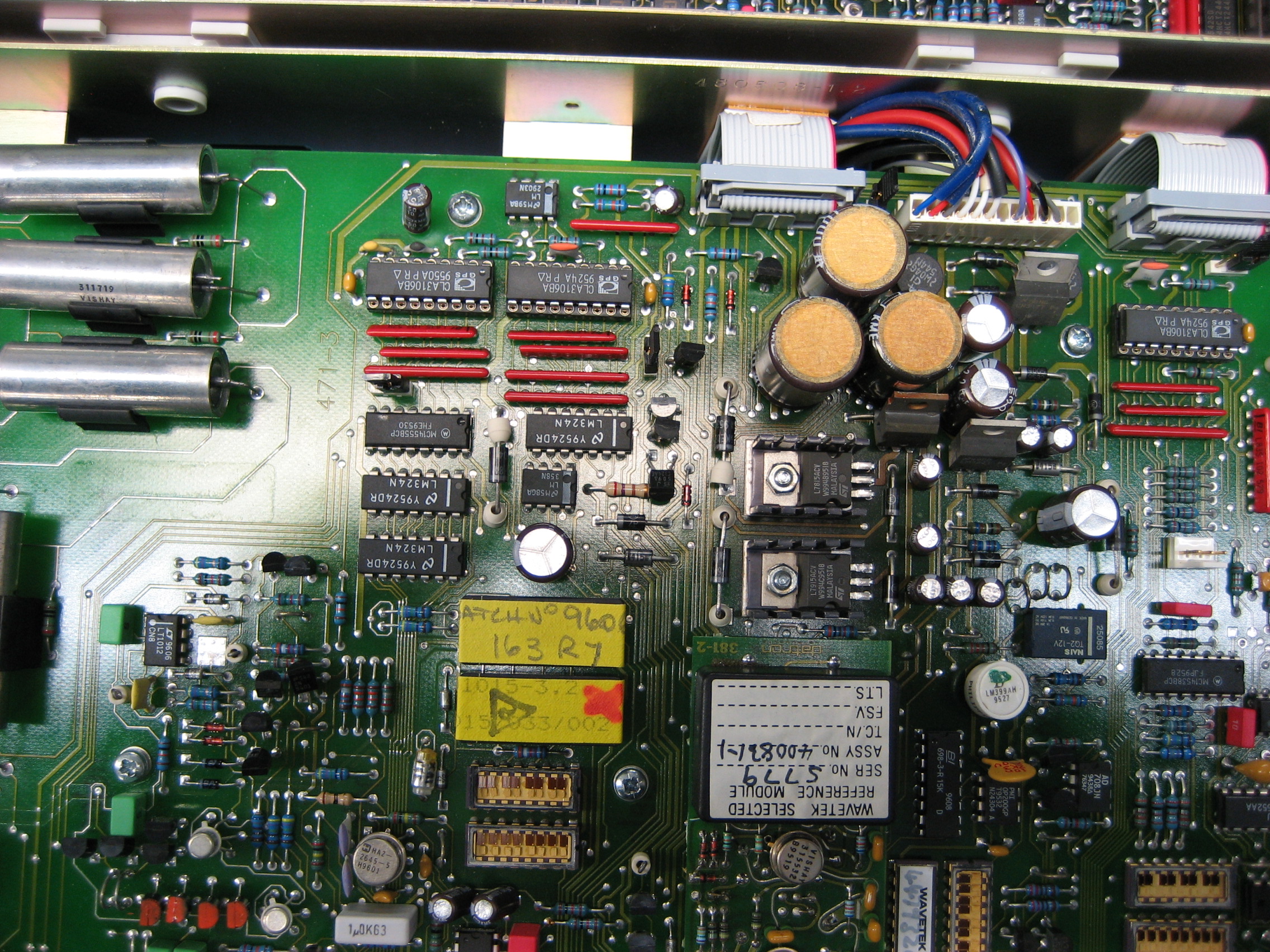
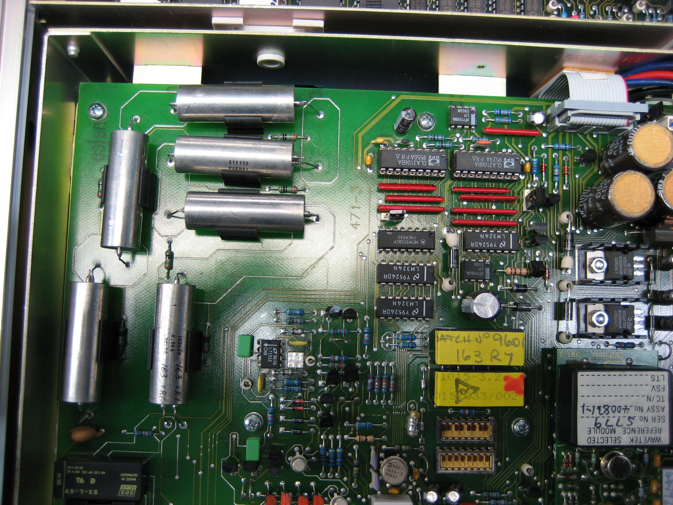
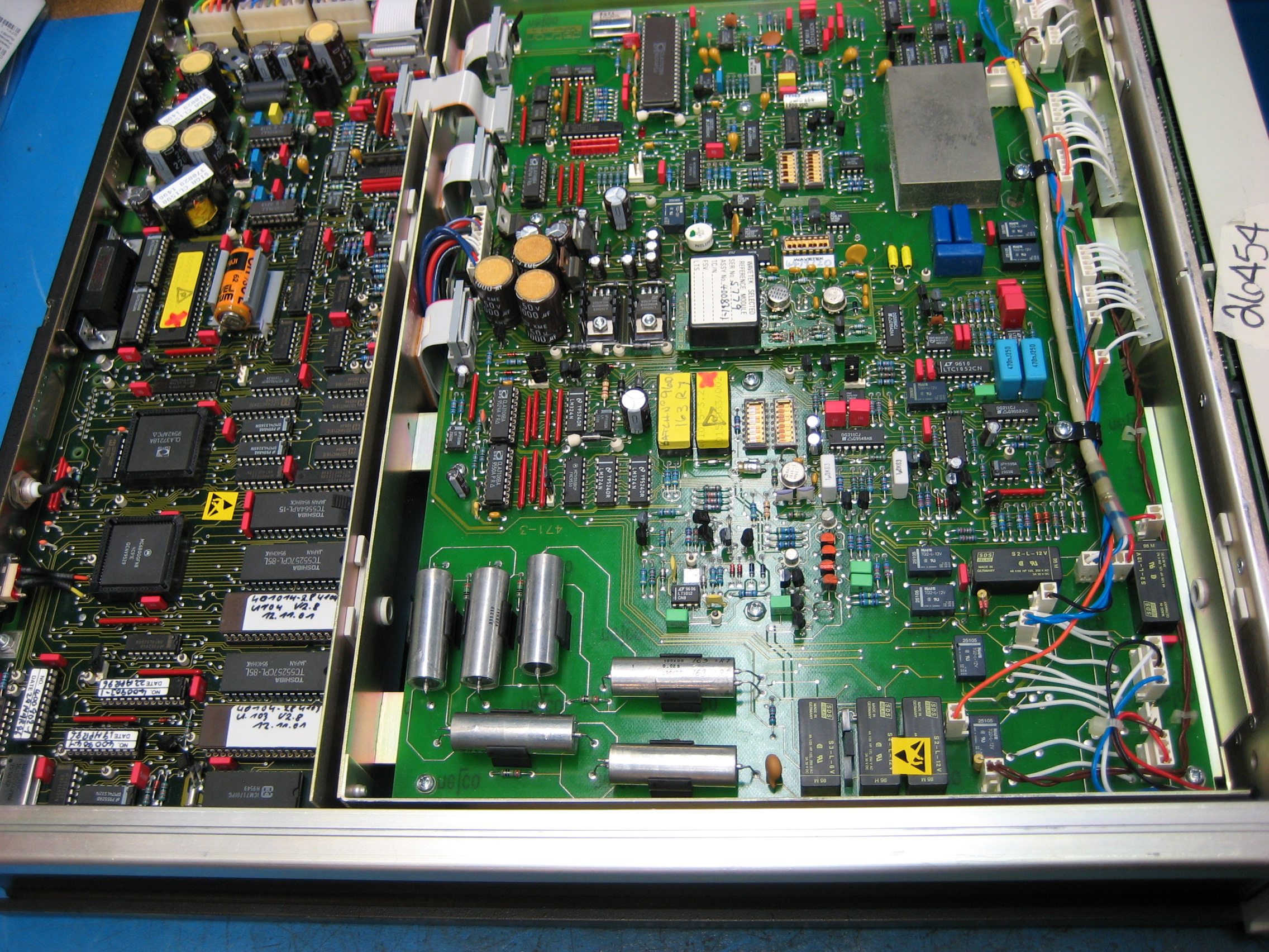
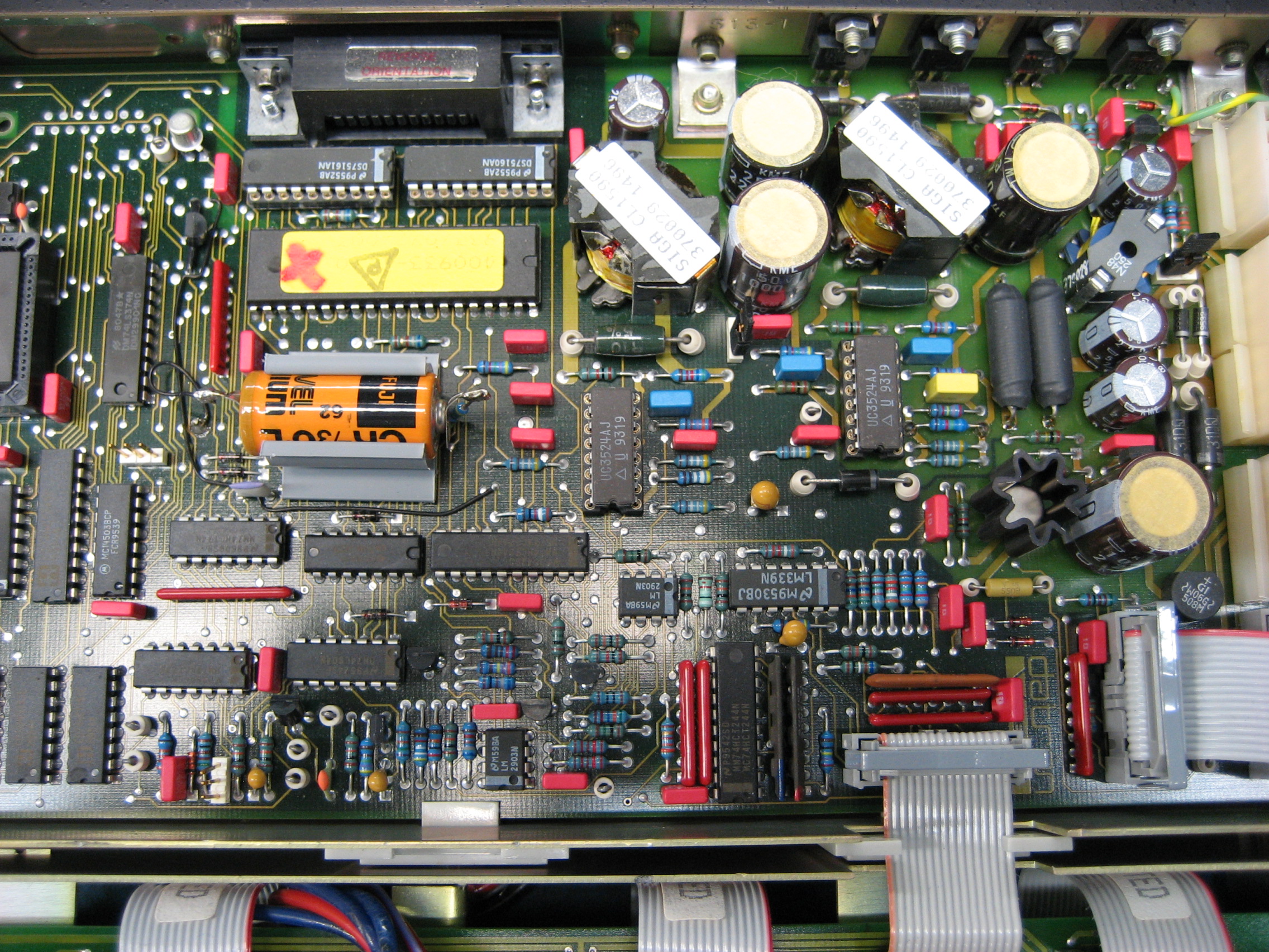
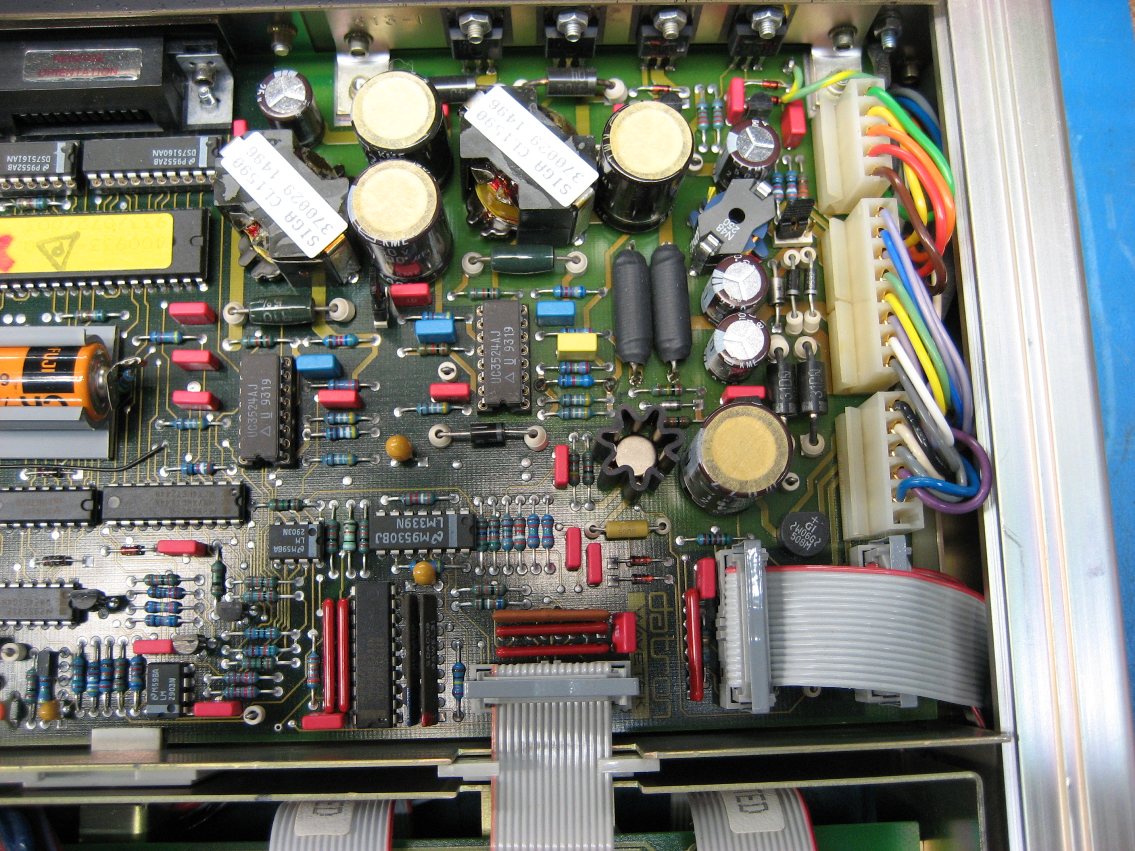
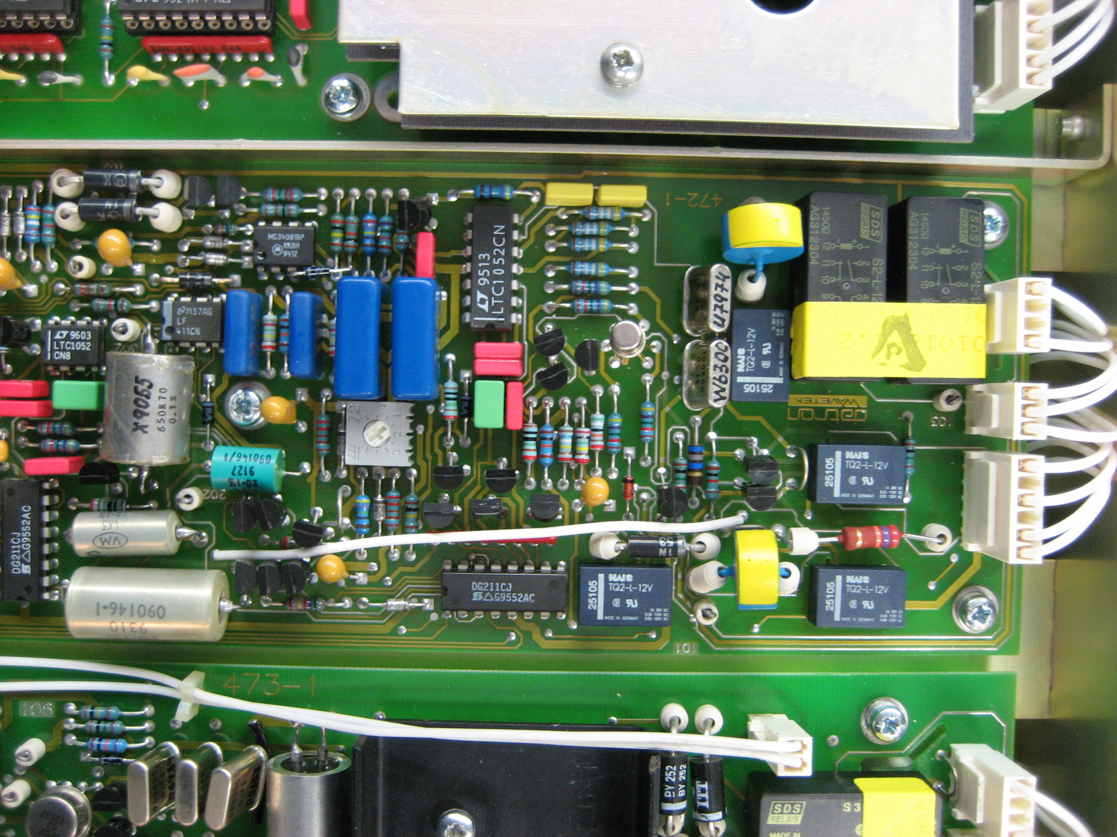
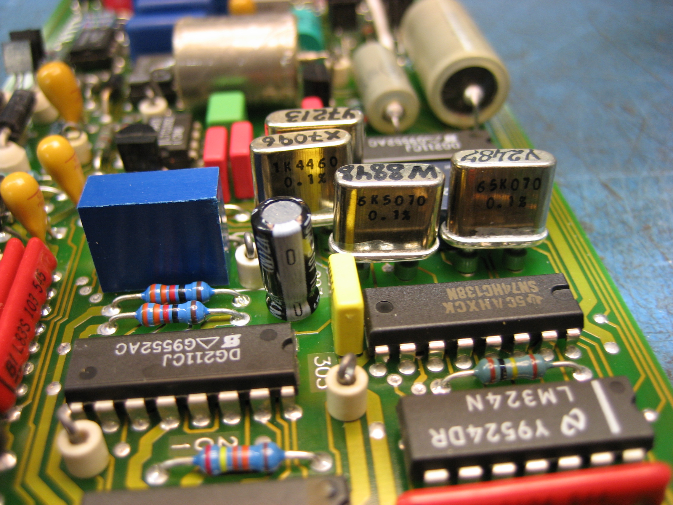
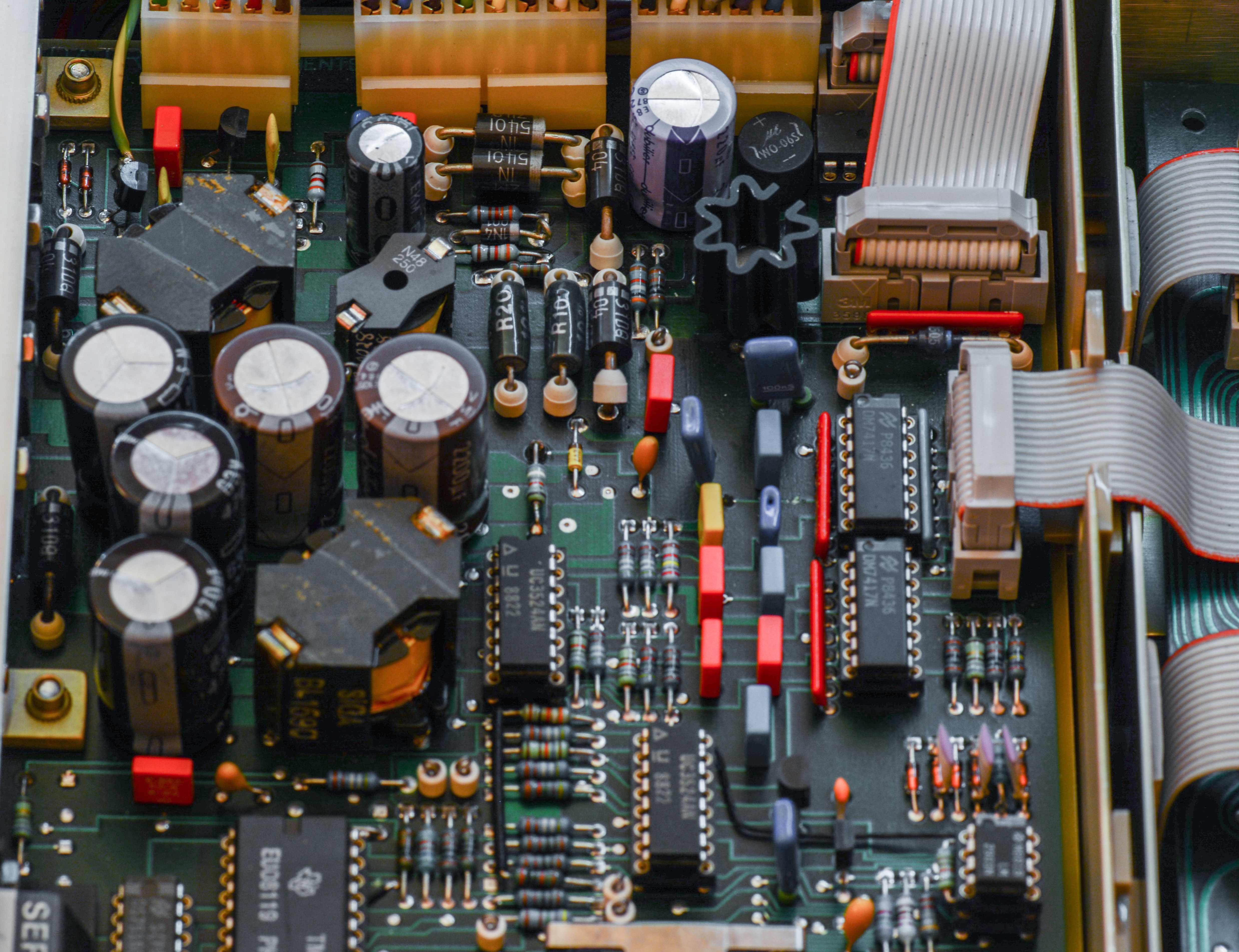
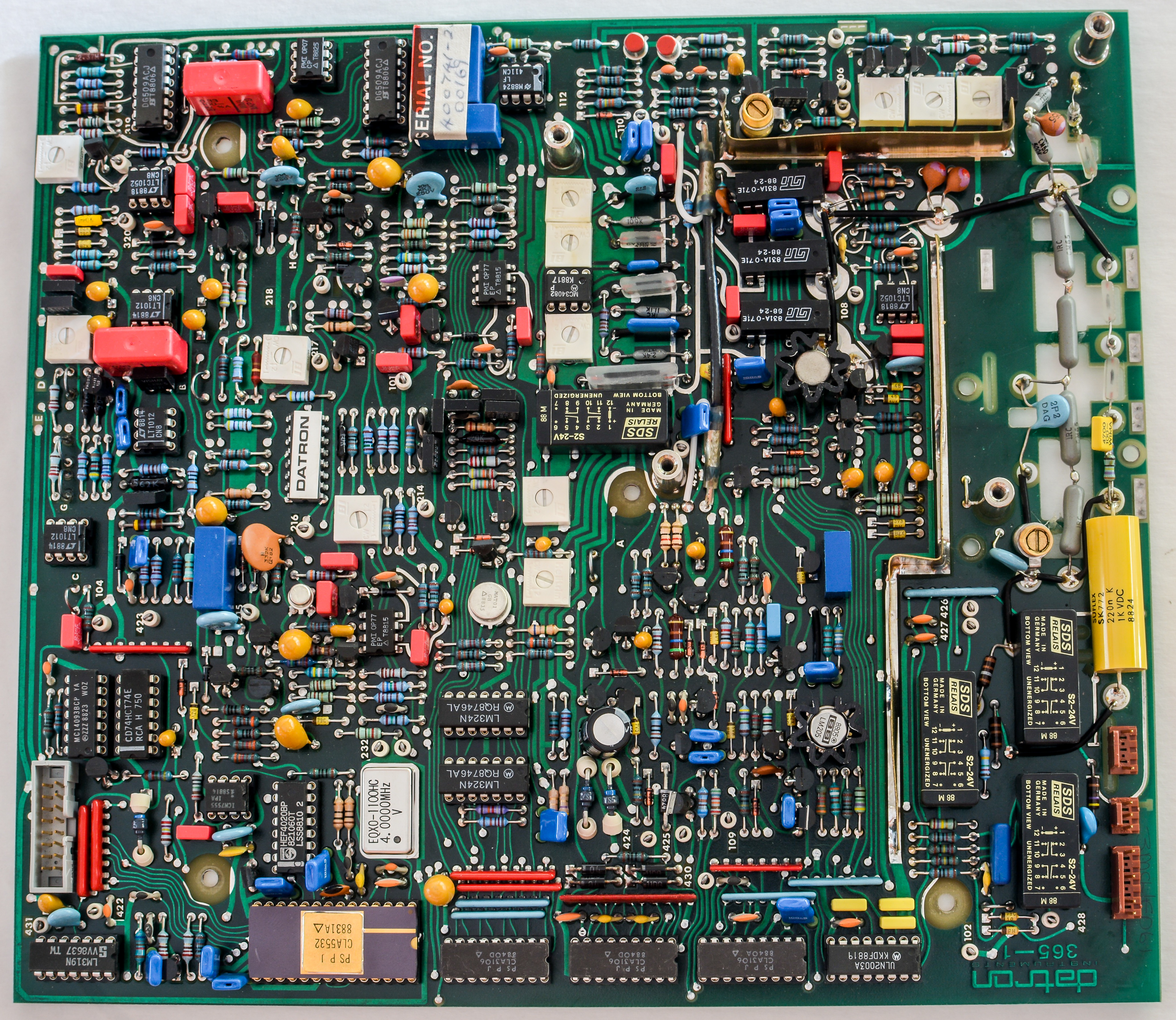
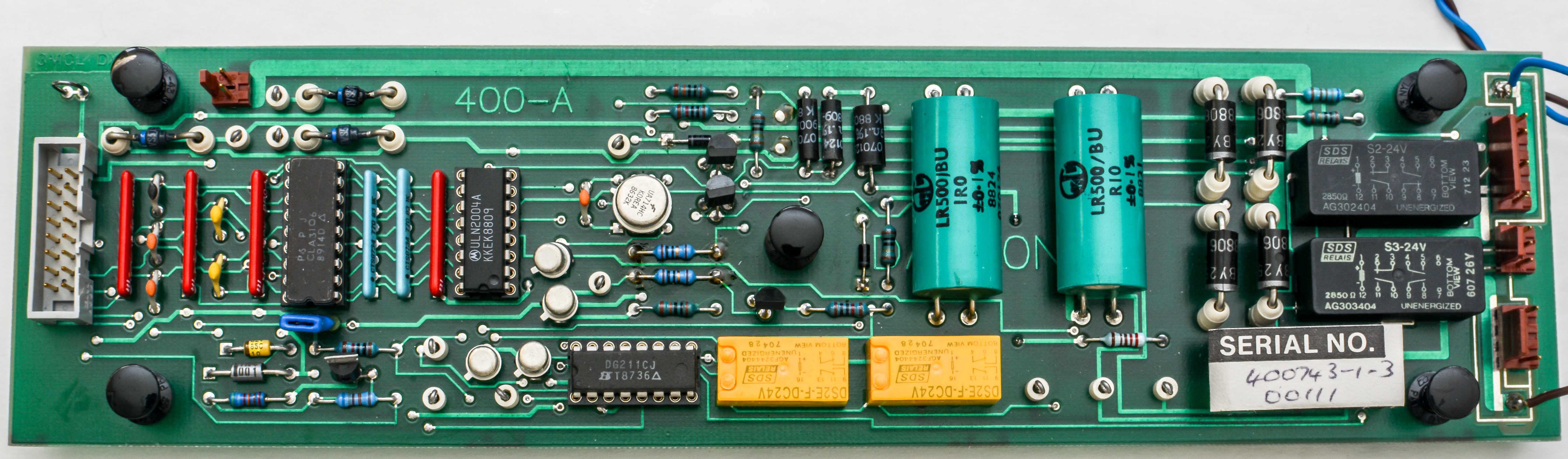
DCV board assembly
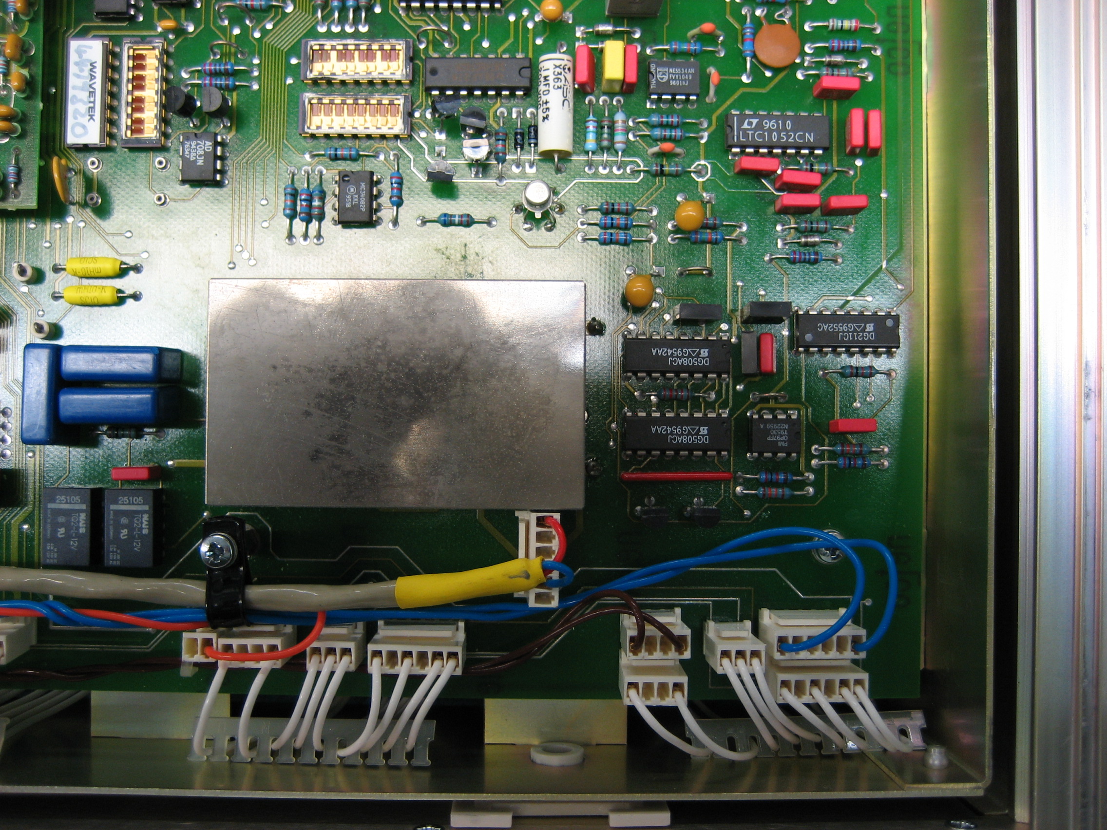
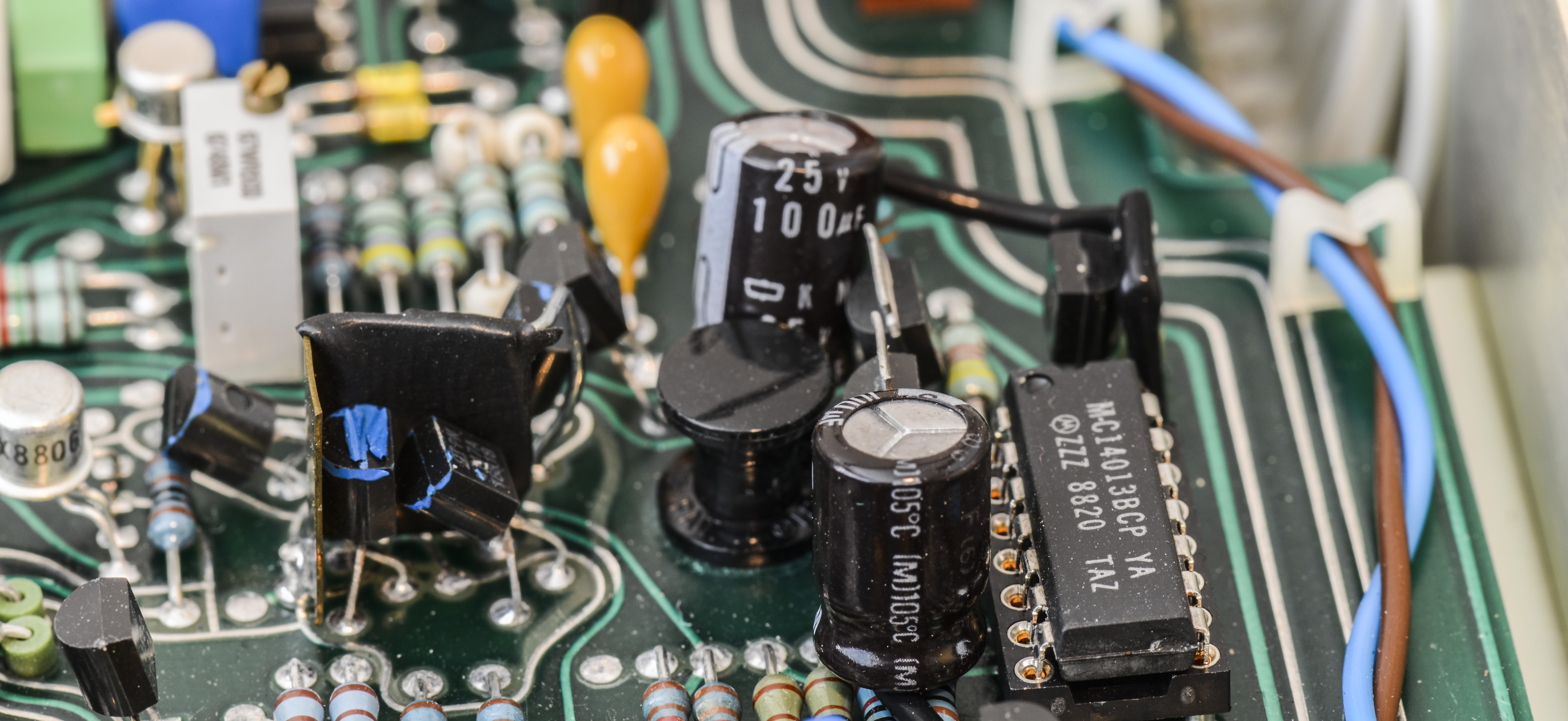
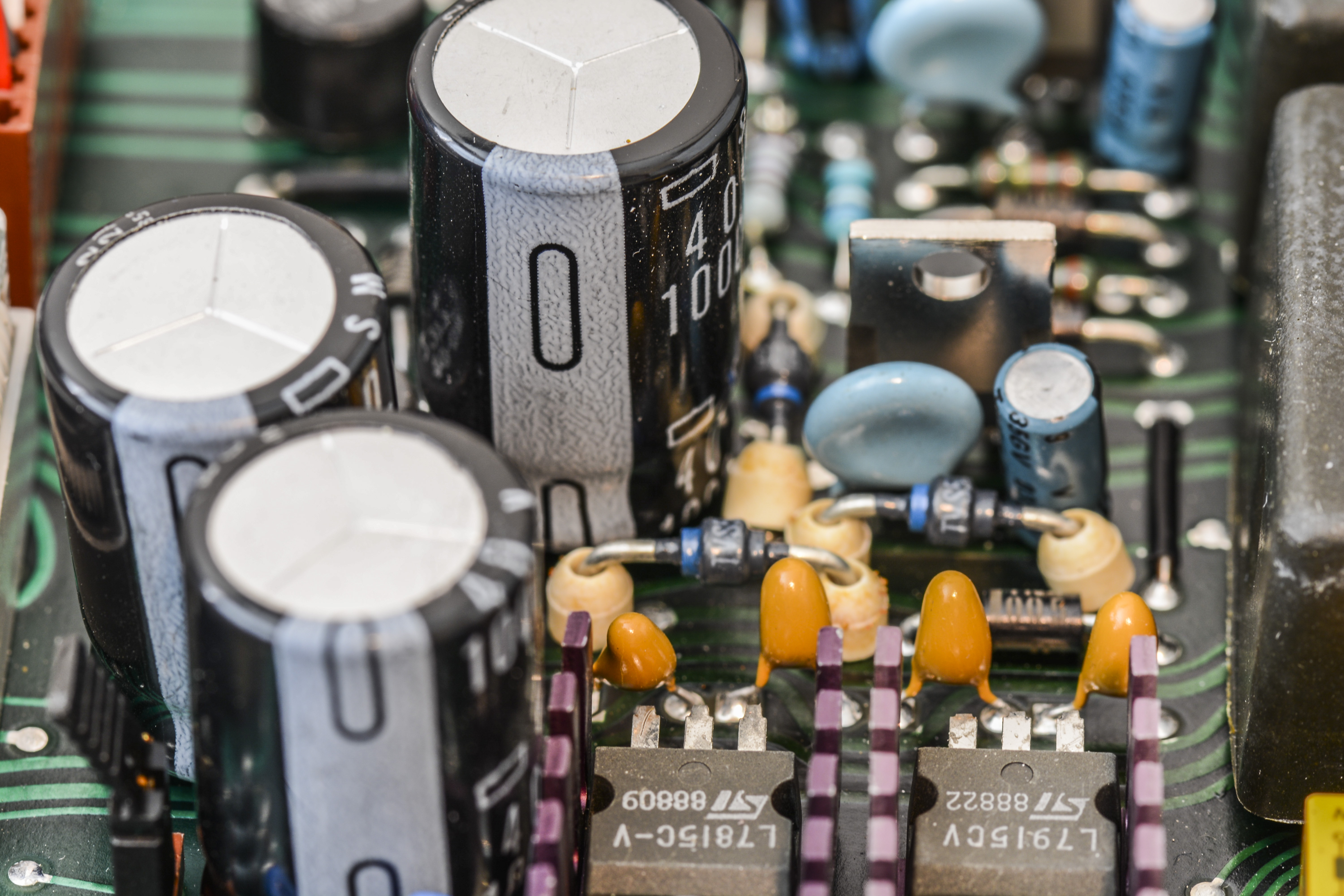
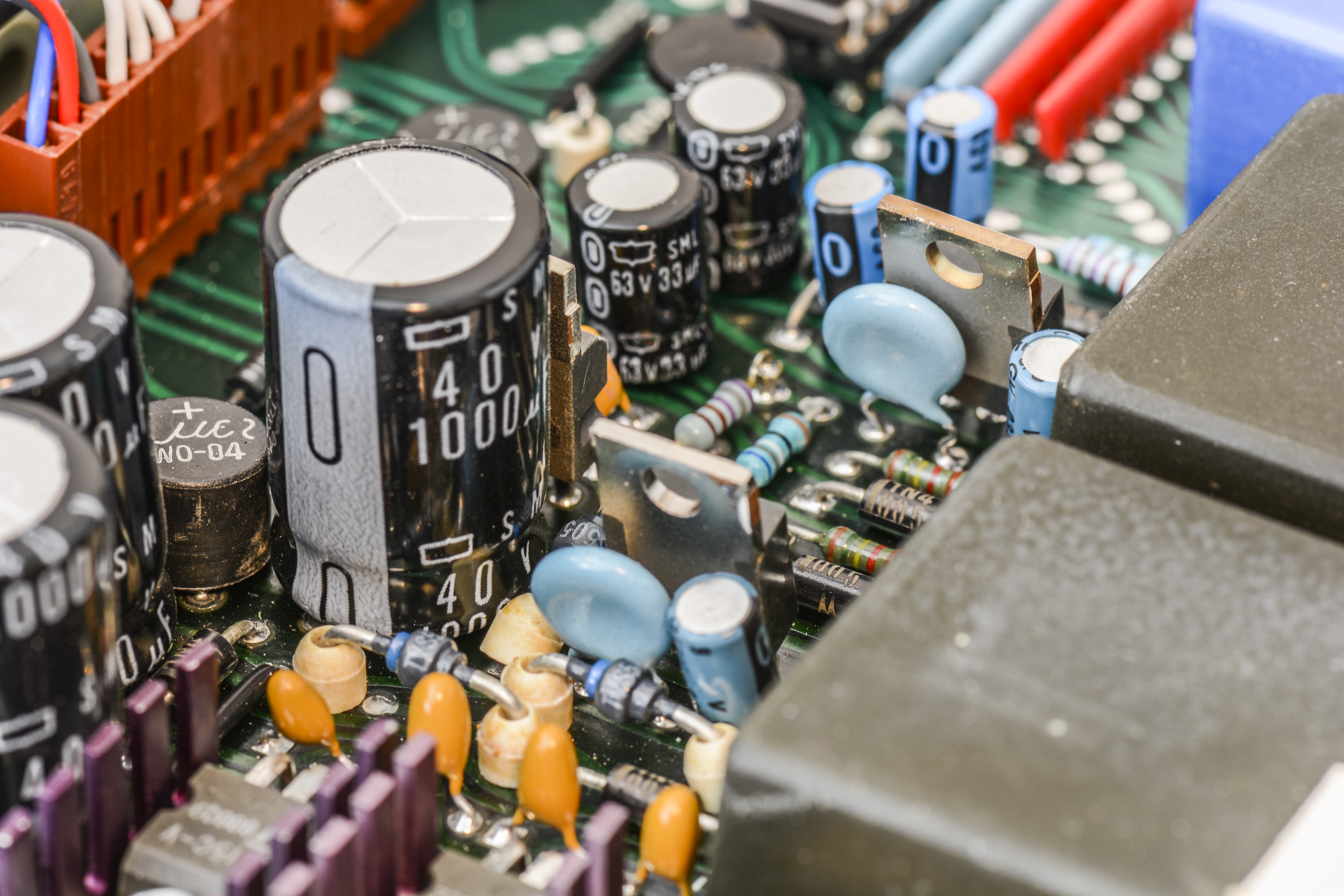
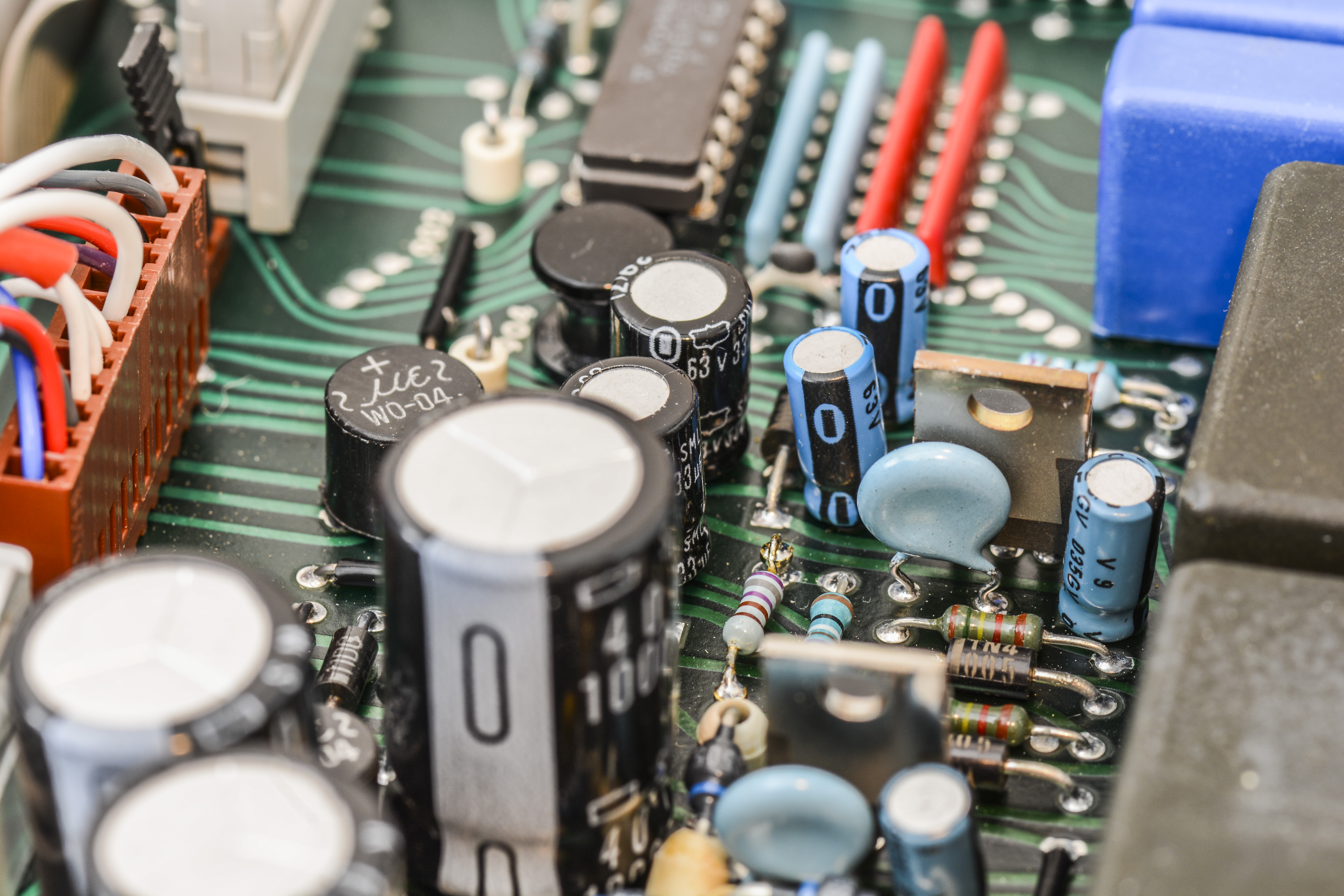
All but two capacitors were replaced on the DC board (12 of 14). A couple of gotchas were found during the change out. The three 1000 µF caps had one lead bent offset to the bottom. It appears the mounting holes were too close together and did not match capacitor pin spacing. Another gotcha is that it is important to note which lead is offset as there are some components that will prevent it from going in properly. Two of the capacitors actually would touch each other and this is solved with the offset leads.
Another gotcha is that most of the four 100 µF capacitors leads are not soldered straight to the board. At least one positive lead is soldered to the pcb in through a pad but it is not usually shaped for the polarity (square-vs-round). The other leads are soldered straight to components with insulating sleeves. Two of these capacitors were relatively easy to remove by clipping them at the mating lead. The old lead was left on the part and the new lead was soldered next to it. There was concern that additional heat could have caused issues with the aging parts. The other two capacitors were surrounded by other parts preventing them from being changed easily. It was decided to continue troubleshooting at this moment and replacing them would have been done later.
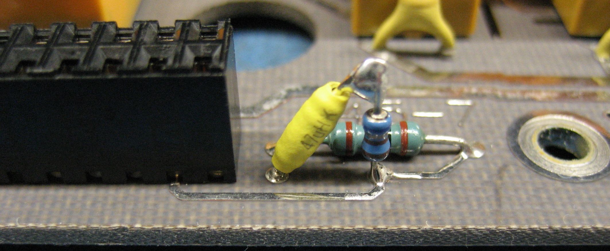
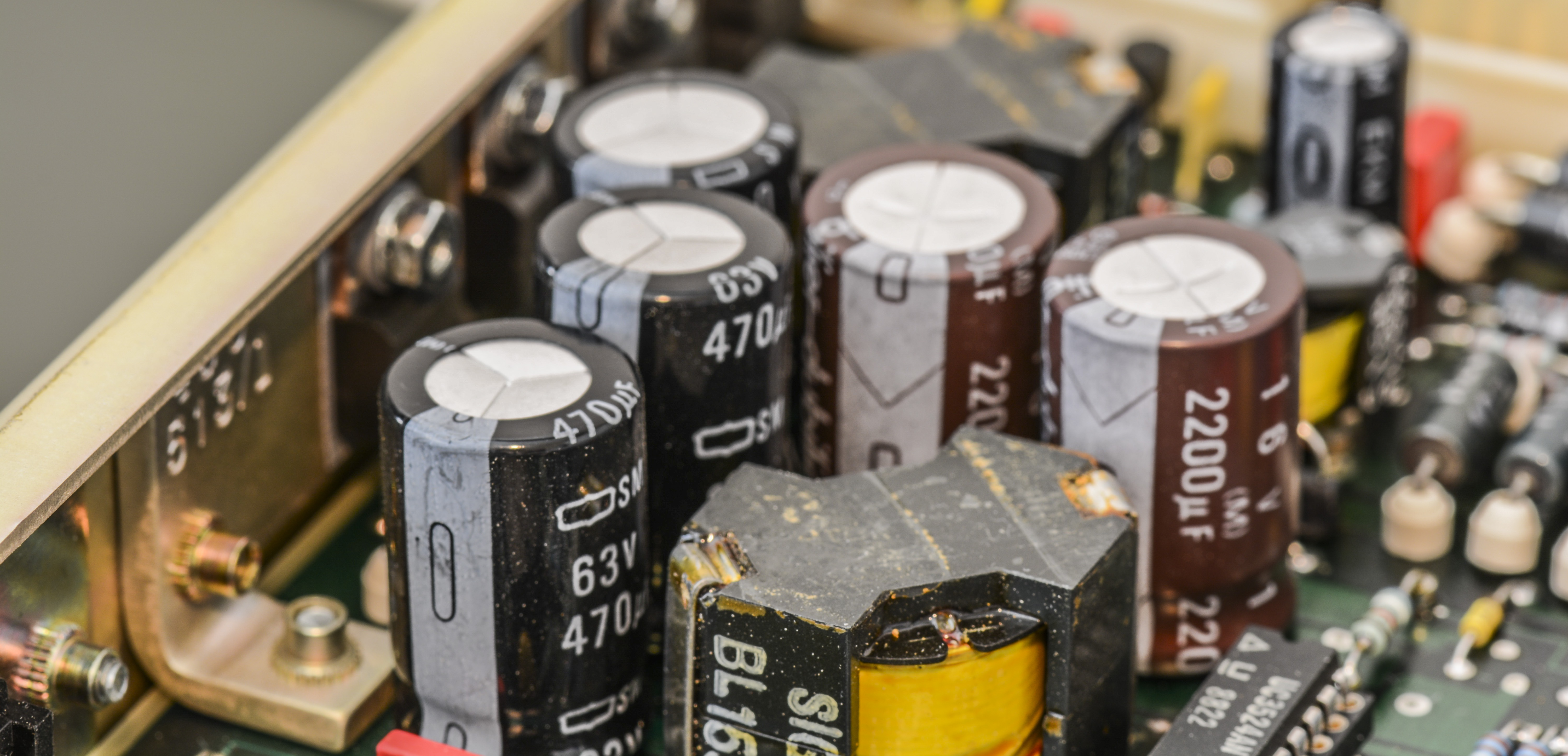
The 470 µF cap was replaced with a higher rated voltage. The new part is as tall as the three 1000 µF caps. The lid has polymide tape directly above the three parts so the same precaution was added above the 100 µF cap.
The remaining capacitors had no additional gotchas.
An IET DE-5000 was used to measure the 1000 µF capacitors for value and ESR. The old parts were at least 20% below rated capacitance and the ESR was approx 1Ω @ 120Hz. In comparison, the new parts were all within 10% and the ESR was < 0.1 Ω.
Compressed air was used to clean the dust and debris from the DC PCB. The board was reinstalled in meter and the FAST SELF-TEST was performed several times over the period of several hours. All tests completed now without errors.
Here’s BOM list of parts used for repairs:
| Digikey Part Number | Vendor | Part Number | Specification | Customer Description | Quantity |
|---|---|---|---|---|---|
| 493-1647-ND | Nichicon | UHE1J471MHD6 | 470 µF/63V | 10000H/105 °C 7.5mm/sp | 2 |
| 493-1622-ND | Nichicon | UHE1H102MHD6 | 1000 µF/50V | 10000H/105 °C 7.5mm/sp | 4 |
| 493-6802-ND | Nichicon | UHW1E222MHD6 | 2200 µF/25V | 10000H/105 °C 7.5mm/sp | 2 |
| 732-9242-1-ND | Wurth Electronics | 860040778011 | 270 µF/63V | 10000H/105 °C 5mm/sp | 1 |
| 493-6817-ND | Nichicon | UHW1H221MPD | 220 µF/50V | 10000H/105 °C 5mm/sp | 1 |
| 732-9325-1-ND | Wurth Electronics | 860240578010 | 470 µF/35V | 10000H/105 °C 5mm/sp | 1 |
| 732-9281-1-ND | Wurth Electronics | 860240474005 | 100 µF/25V | 8000H/105 °C 3.5mm/sp | 4 |
| 493-14361-ND | Nichicon | UBT1J330MPD | 33 µF/63V | 2000H/125 °C 3.5mm/sp | 2 |
| 732-8966-1-ND | Wurth Electronics | 860020772005 | 1 µF/63V | 2000H/105 °C 2mm/sp | 4 |
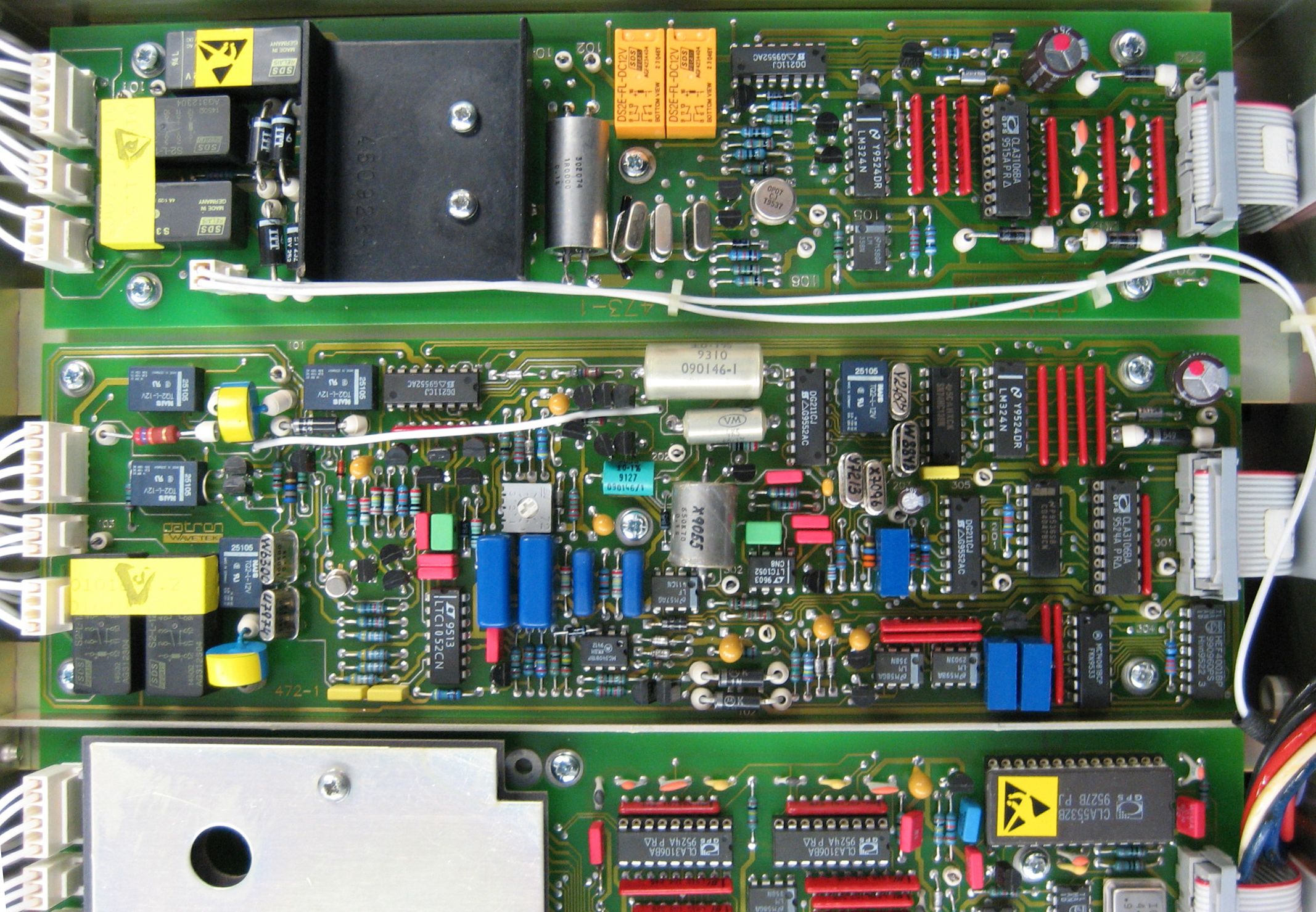
Now time for option boards, located on bottom side of instrument chassis

Option 10 – True RMS AC Converter

No issues were noted with the AC assy. It was inspected, photographed, and dust/debris were removed before it was reinstalled.
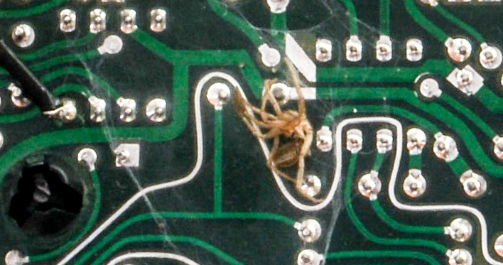
Option 20 – 2-Wire & 4-Wire Resistance Converter
After removal of Option 20 PCBA remnants of spider with it’s home was detected. That likely caused some excessive currents flow thru webs and poor bug, causing measurement issues.
No issues were noted with the Ohms assy. It was inspected, photographed, and dust/debris were removed before it was reinstalled.
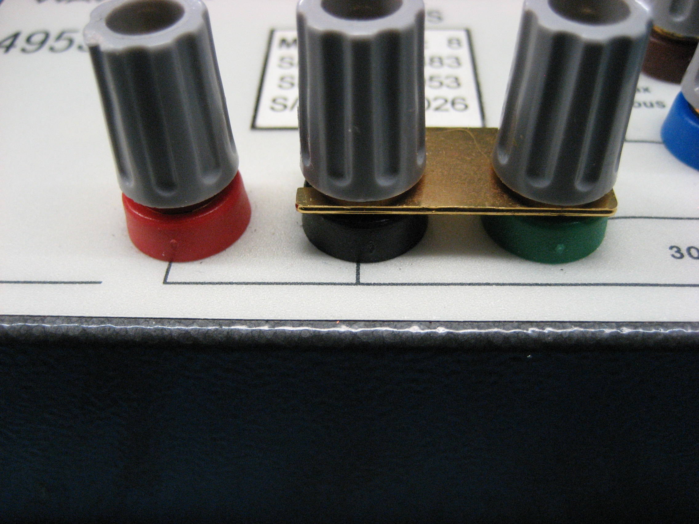
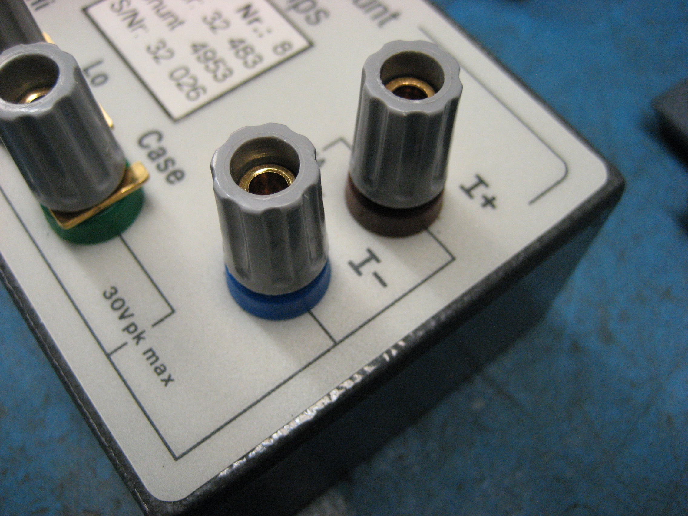
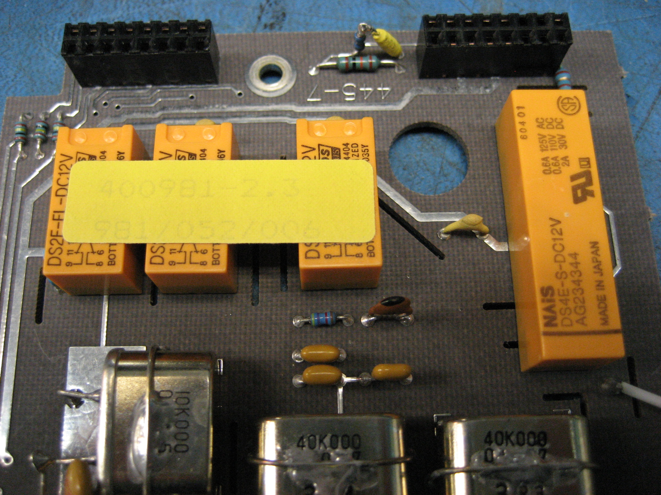
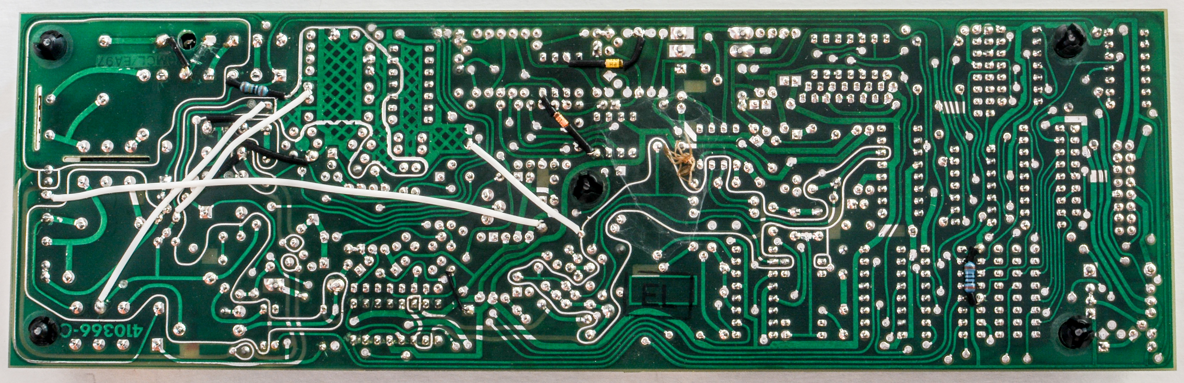
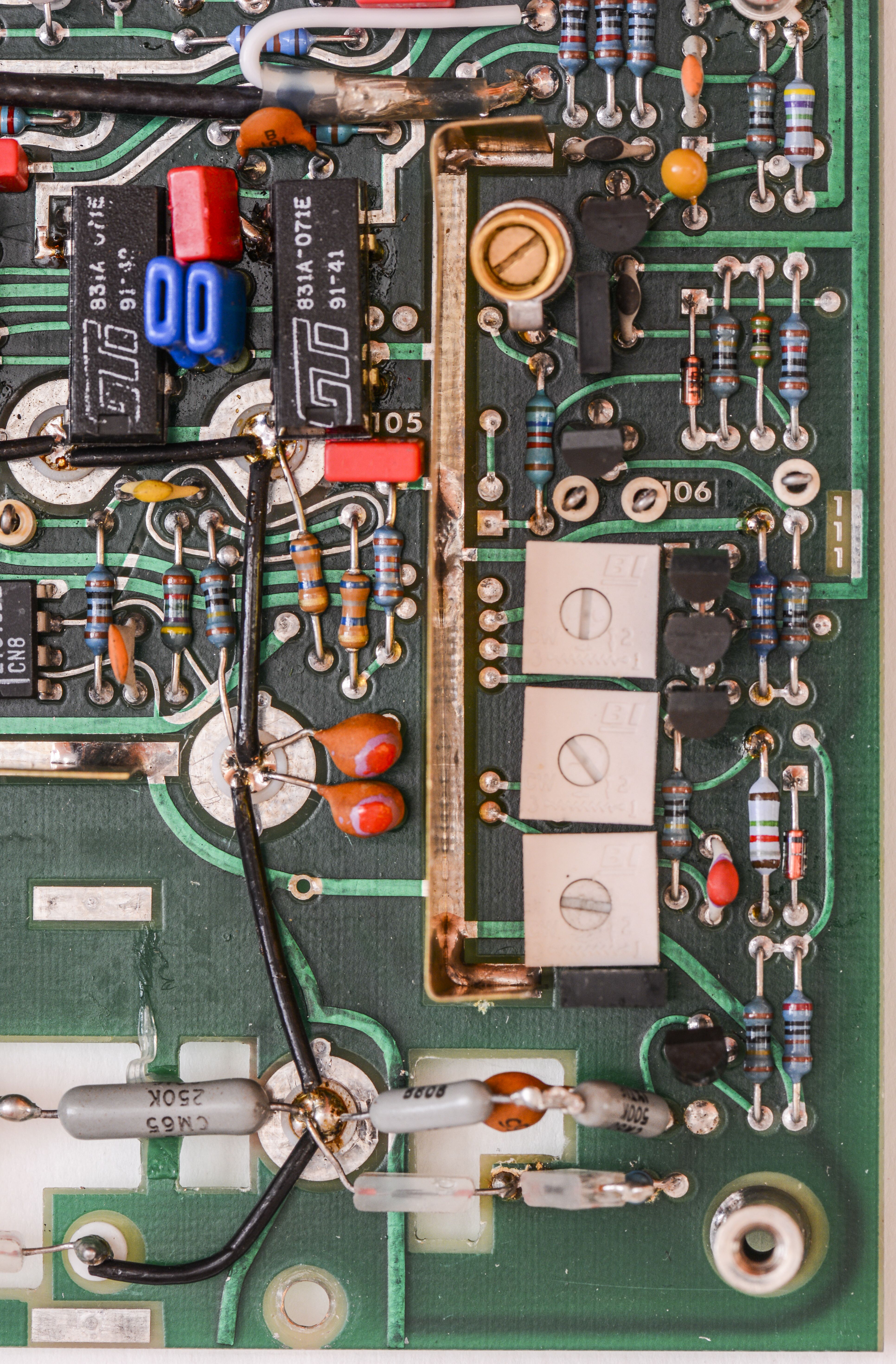
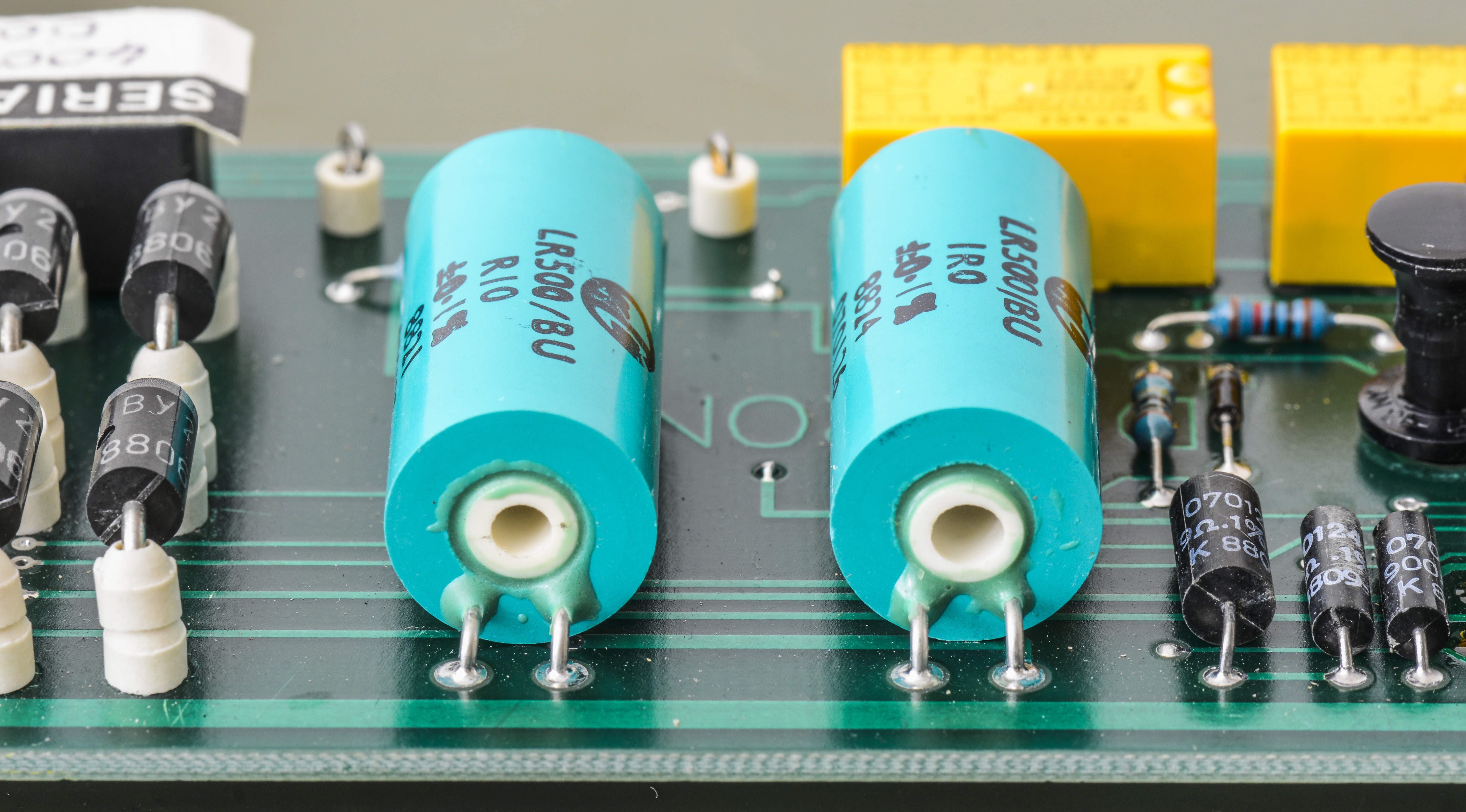
Option 30 – Current Converter

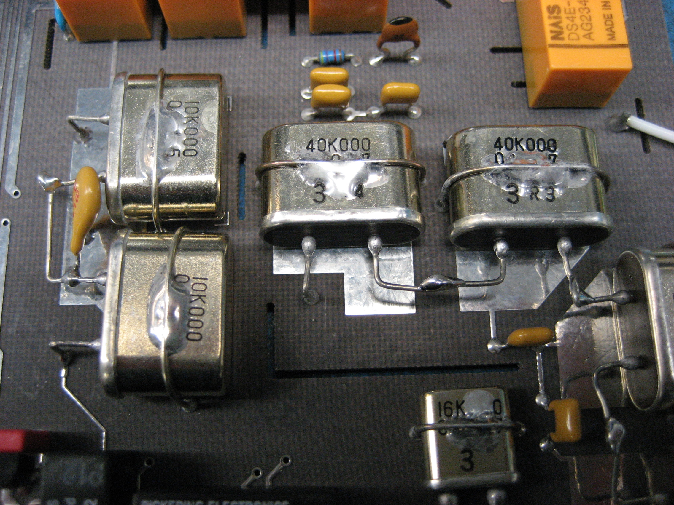
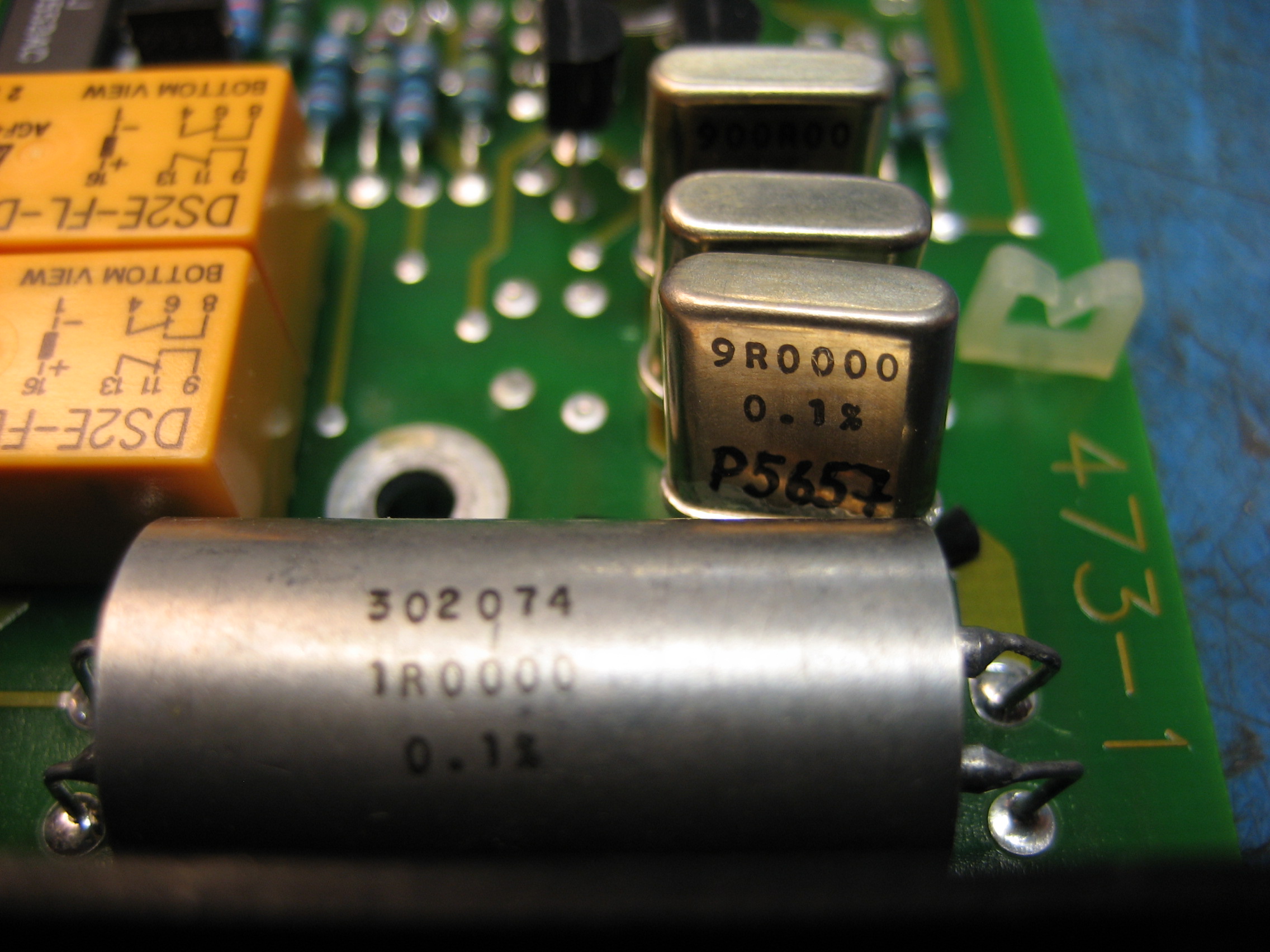
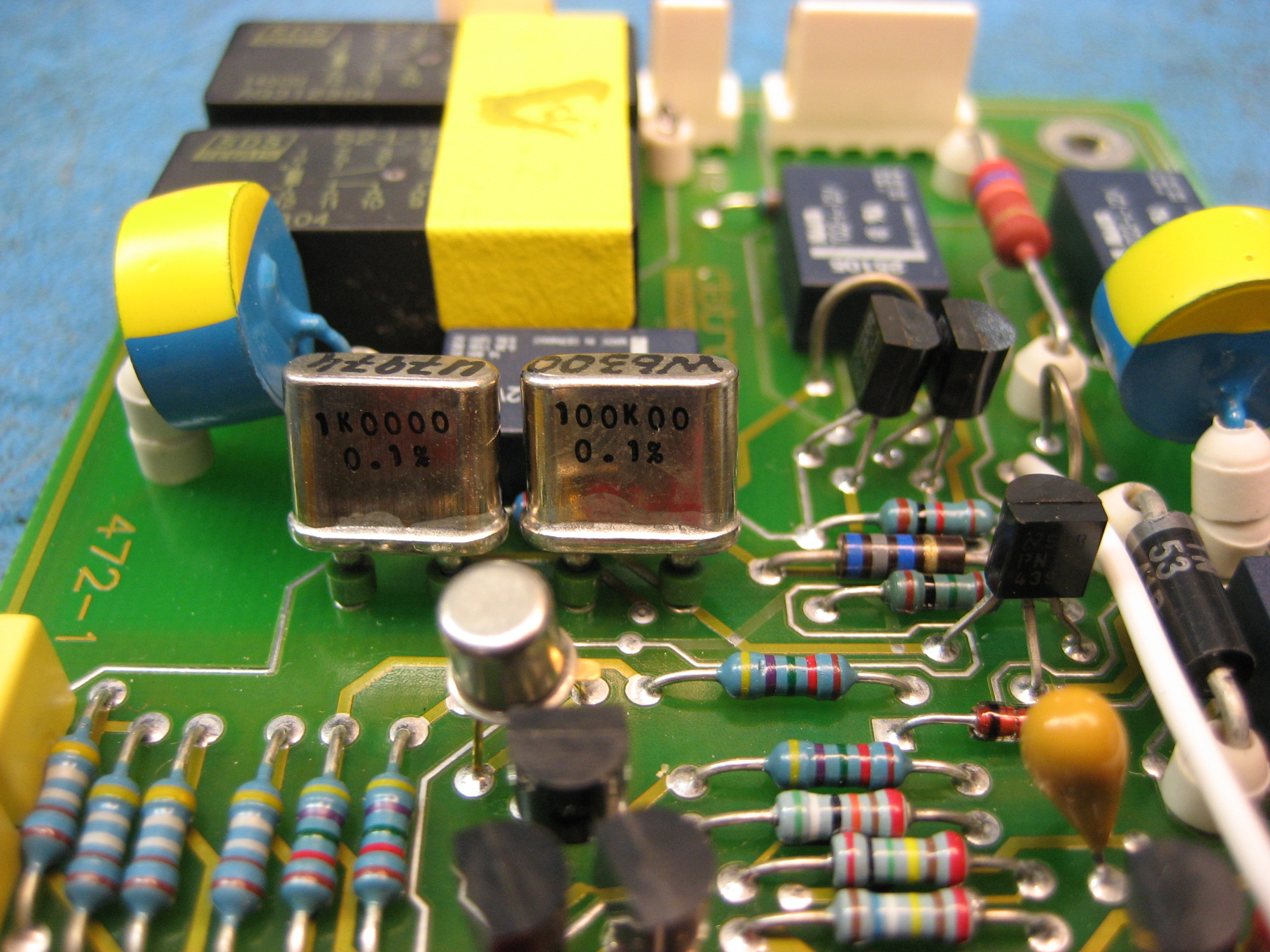
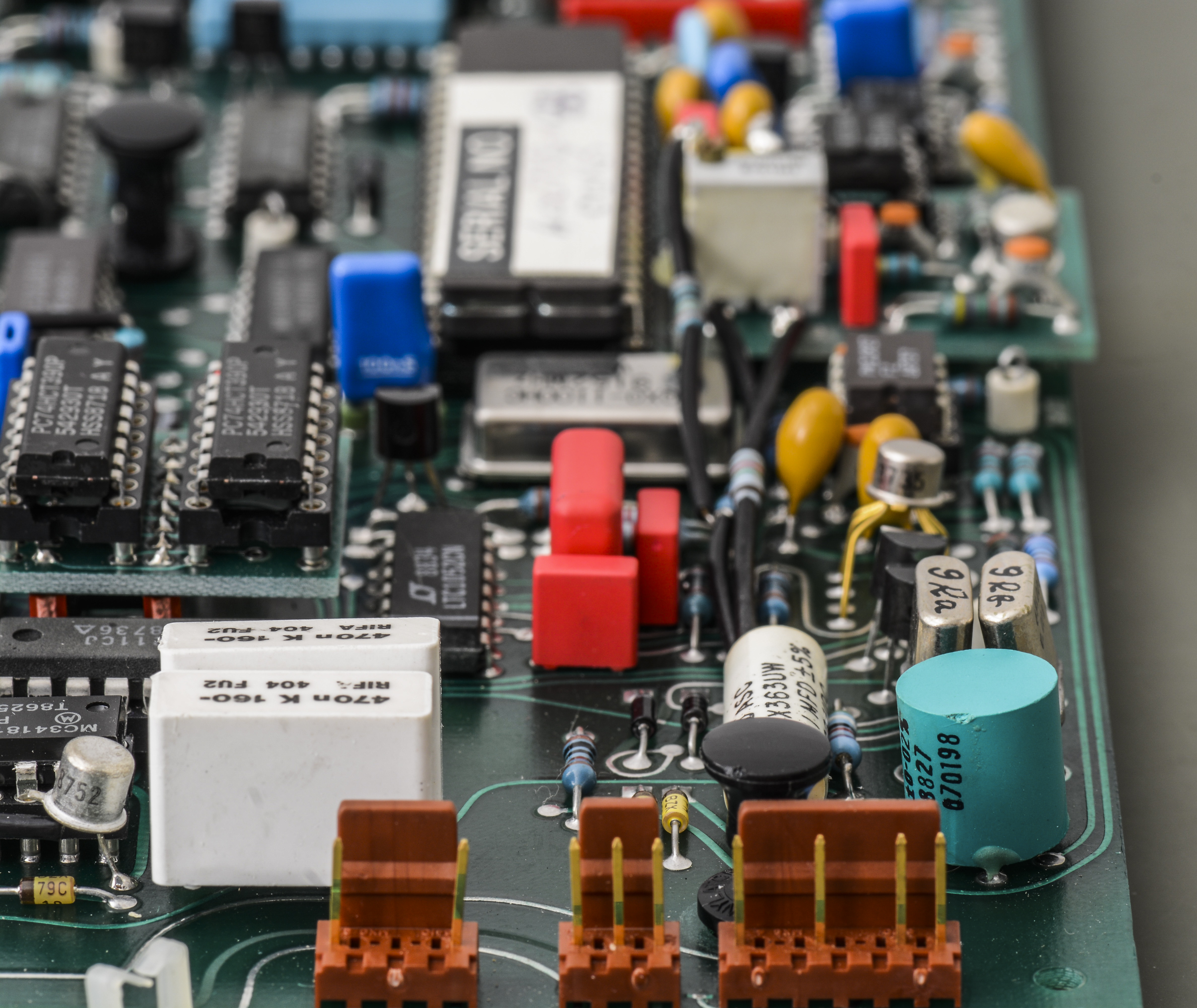
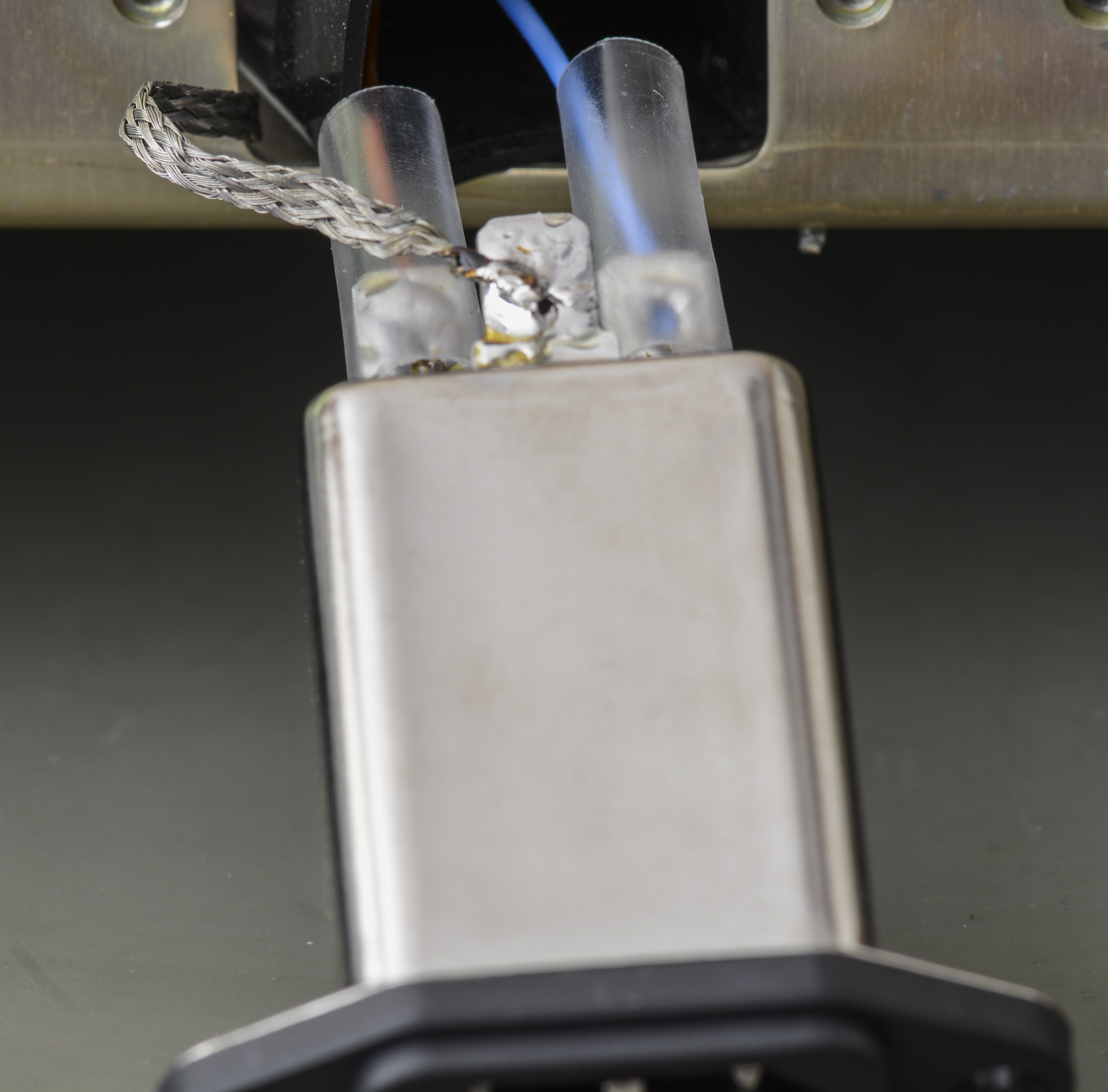
Current shunt resistor network consist of separate set of resistors:
| RefDes | Value | Specification | Manufacturer |
|---|---|---|---|
| R111 | 800 Ω | 0.1% | |
| R112 | 90 Ω | 0.1% | |
| R113 | 9 Ω | 0.1% | |
| R114 | 1.0 Ω | 0.1% | Mann Components |
| R115 | 0.1 Ω | 0.1% | Mann Components |
Pair of teal colored precision 4-wire shunts are manufactured by Mann Components Ltd (Ayton Road, Wymondham). Mann Components was an English resistor manufacturer with sales of about $2M. It was bought by Vishay in early 1983.
During reassembly of the bottom half of the meter, it was discovered that the Current assembly had some difficulty with the three connectors at the front of the pcb. Looking at the wires an interesting issue was found. It appears that the two outside connectors were placed in the opposite location. The wires are a little short and there is some noticeable stress. Looking for other photos on the internet, a ’94 era 1281 had the connectors located in the right position.
Other repairs
The lithium battery was replaced with a TL-5101P. The power was left on and a battery powered soldering iron was used.
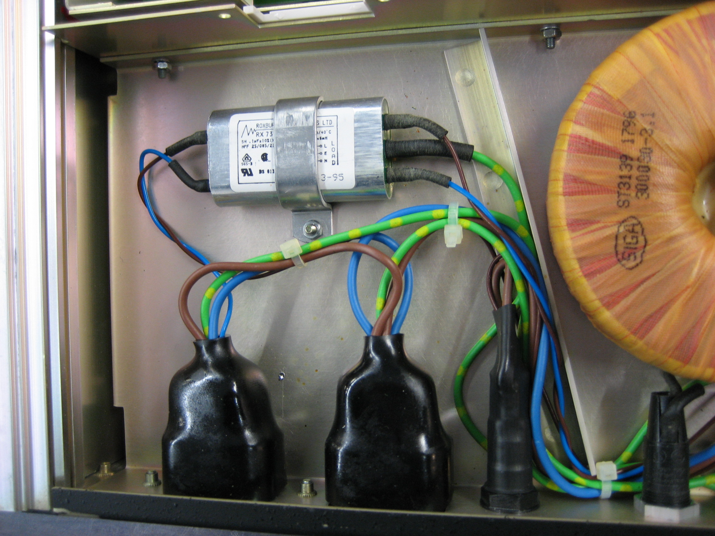
The power input filter was also replaced as a precaution. The old part is a Waycom WF 120-3/05 and it was replaced with a Schaffner FN9222-3-06. The ground cable is exposed so additional heat shrink was added to the P and N terminals.
The power supplies were remeasured. All supplies are close to as-found except the -35V supply. It was now measuring -35.6VDC with 0.13Vp-p noise. The +15V supply measured 15.1 with 0.22Vp-p.
Quick check after assembly, with short on input terminals:
Input DCV +10V test:
Repair workflow, unit #2
This second unit actually happens to be the the first Datron 1281 acquired. It was chosen to repair last repair due to the number of errors.
The NVRAM in this meter is the same as the first 1281 but the battery is a few years newer.

Repair procedure is very similar to previous box. This unit comes with Options 10, 20, 30 and 70, so it have full set of boards and modules to play with.

This unit does not have mount hardware for 19” rack (Option 80) like previous, but comes with foot to angle it on the bench for easier operation. It is still older version of Model 1281, still carry Datron Instruments logo, not Wavetek-Datron like on newer meters.

Model 1281 is rare DMM providing separate active resistance guard terminal, unlike HP 3458A or Keithley 2002. Fluke 8508A have combined Guard terminal, switchable between passive or active mode.
Rear panel is same as first unit, with all the usual connectors and without any fans or vent holes. Keylock to enable calibration mode on this unit is damaged by previous owner, likely by attempts of using wrong key. This is rather unusual today to see such hard keylock to protect calibration, but back then it was easy go-to solution.
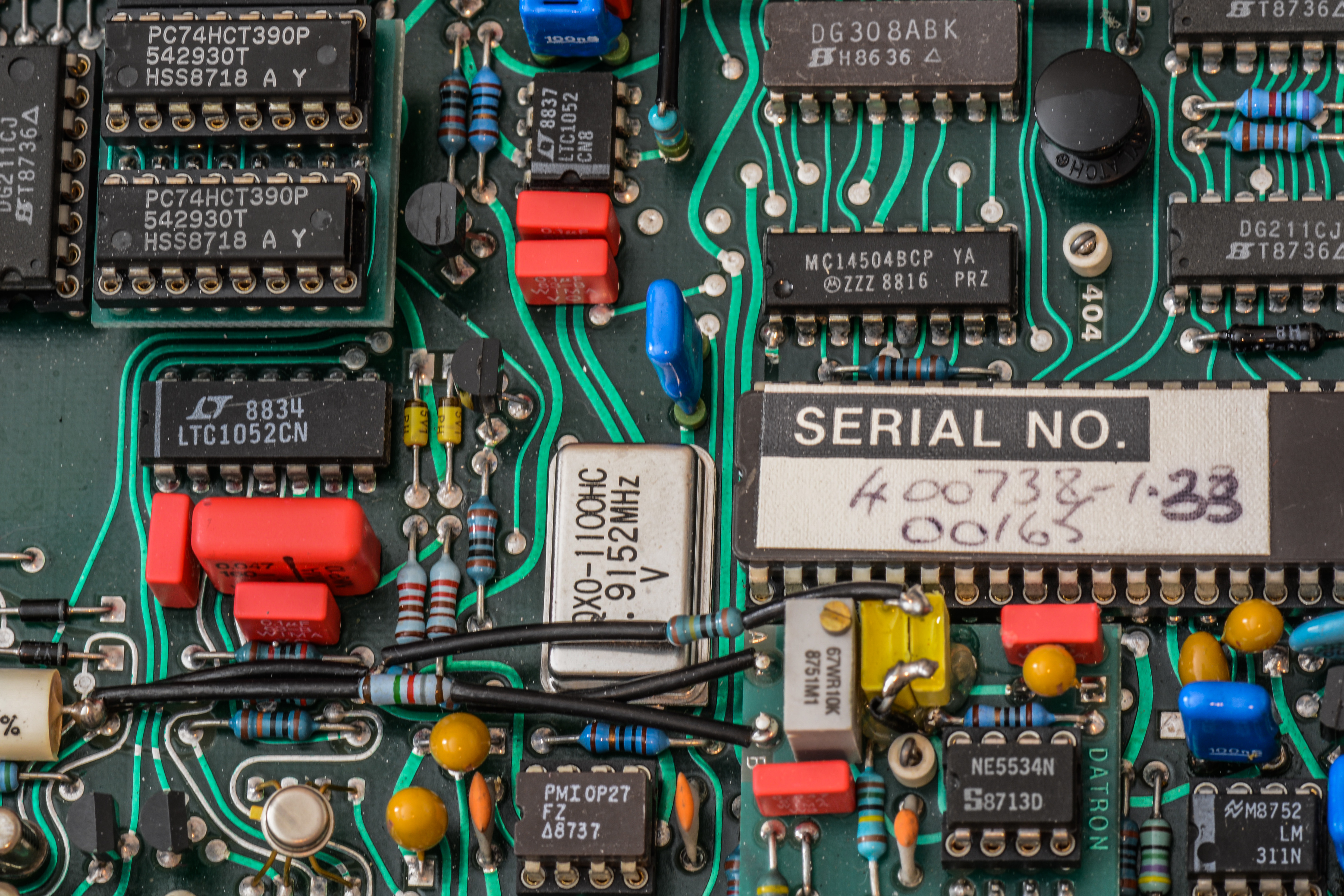
Of course it’s just single pole switch and any dedicated calibration pirate cannot be stopped by simple lock, as photo above able to indicate well. ROM/RAM chips have same style paper-written labels with version/serial number.
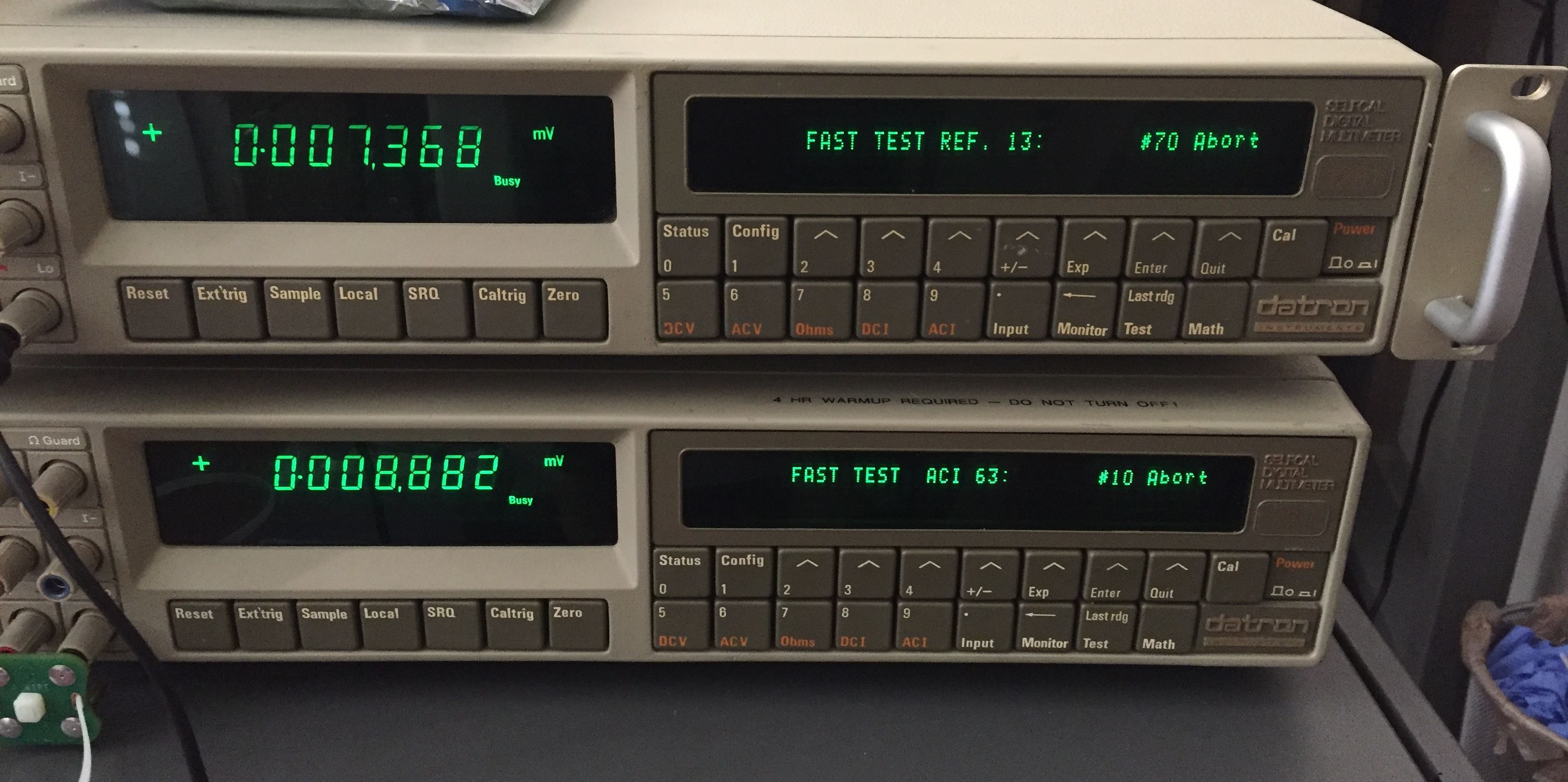
The fast self-test returned the following errors including test limits from the service manual:
| Error code | Limit min | Value description | Limit max |
|---|---|---|---|
| DCV 2182 | -250uV | Mean 100mV Zero | +250uV |
| Ohms 2752 | +0.01FR – 4% | Mean Magnitude | +0.01FR + 4% |
| DCI 2572 | -50ppm of FS | Mean Magnitude | +50ppm of FS |
The 2752 and 2572 test both use the Ohms 10mA current source. The current source was tested using Keithley Model 2002 as control meter. The 2002 showed a low noise source but the value was nowhere near specifications. Most likely the calibration constants are too far off.
It is hoped that the capacitor replacement will cure the DCV 2182 Error as it did on the first meter. The power supplies will need to be checked first, as usual with old equipment repairs.
Digital board
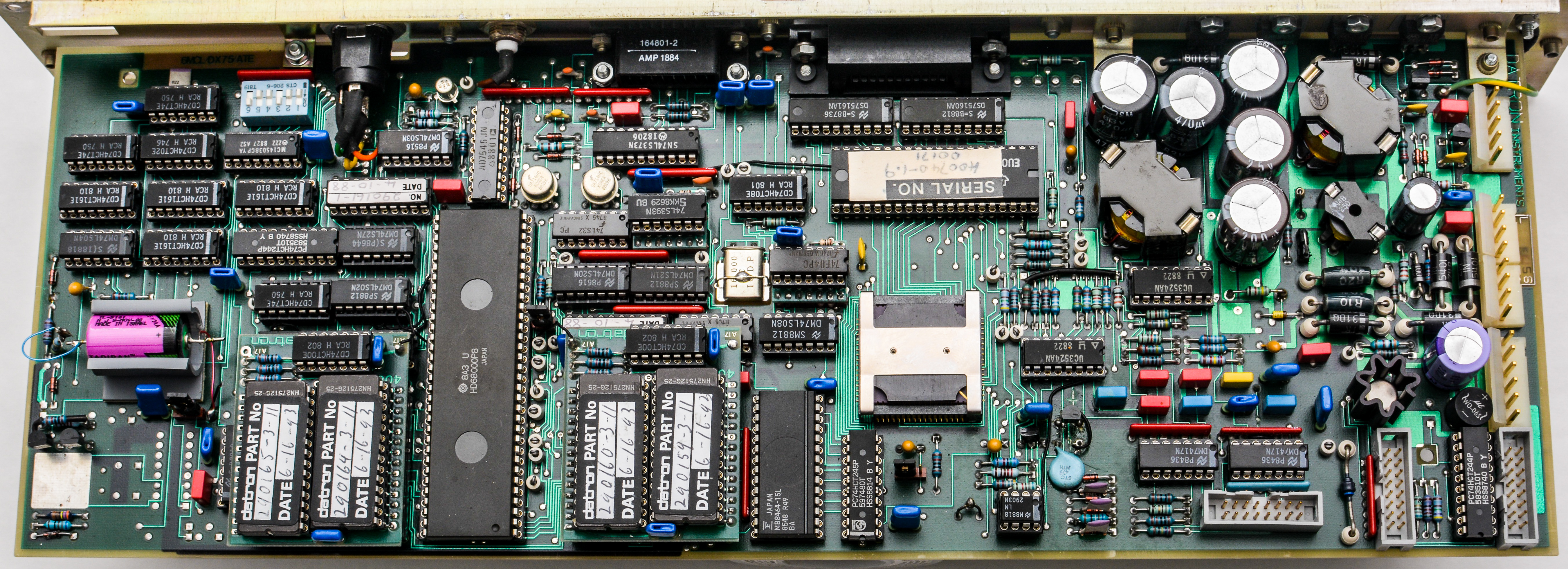
The outguard supplies were measured:

| Test voltage | Ripple on rail | Measured voltage |
|---|---|---|
| +5 V | 0.32 Vpk-pk | +5.02 VDC |
| +45 V | 0.23 Vpk-pk | +47.4 VDC |
The Digital board has firmware version 3.11 installed and is the same configuration as the previous meter with four EPROMs.
All seven capacitors were changed just like the first 1281 while observing if any of the leads needed to be bent to fit the holes in the pcb.
DCV board assembly


A quick test of the inguard supplies on the DC board showed the following values:
| Test voltage | Ripple on rail | Measured voltage |
|---|---|---|
| TP901 (+15V) | 0.1 Vpk-pk | +15.1 VDC |
| TP902 (-15V) | 0.06 Vpk-pk | -15.0 VDC |
| TP903 (+35V) | 0.10 Vpk-pk | +35.5 VDC |
| TP904 (-35V) | 1 Vpk-pk | -28.9 VDC |
| TP905 (+5V) | 0.08 Vpk-pk | +5.0 VDC |
The -35V supply is ~6V low and needs to be retested after cap replacement. The supply uses a standard LM337T negative adjustable 3-terminal regulator. Based on the DC Assy schematics, the -35V only goes to the Current assy.
All electrolytics were replaced except the four 100µF caps. After the first repair, it was determined to wait and see if the meter would still pass diagnostics based on the chances of damaging another part. It was noticed that the capacitors from both meters were the same make/model/value so it is likely they were original parts from around 1988.
Compressed air was used to clean the dust and debris from the DC pcb. Some cobwebs were also found around the power supply area. The board was reinstalled and the fast self-test was performed. The original three errors were gone, but a new error had been added from the AC assy.
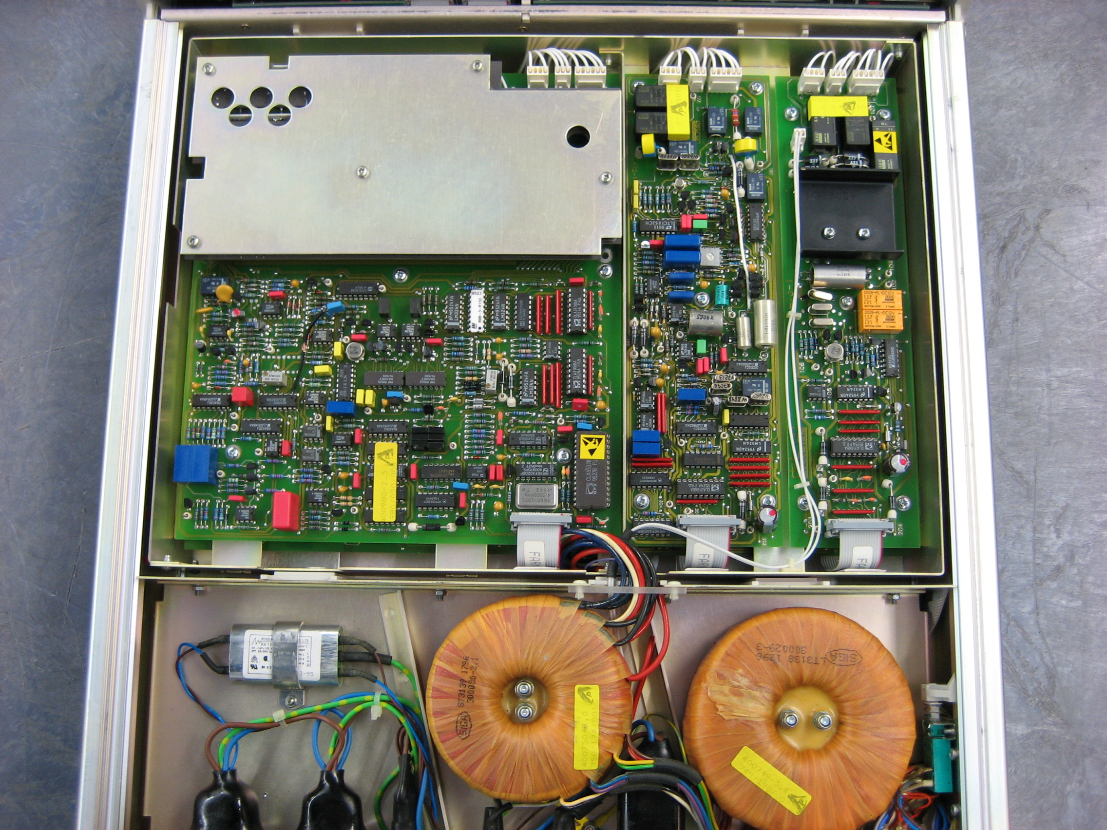
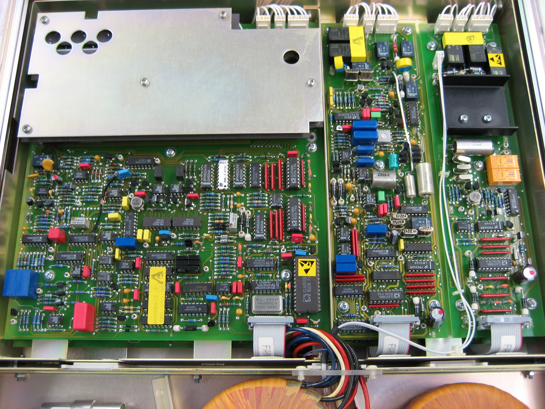
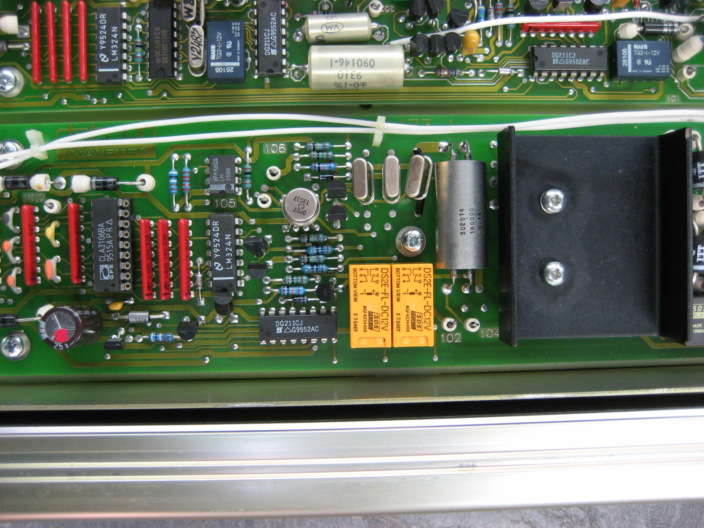
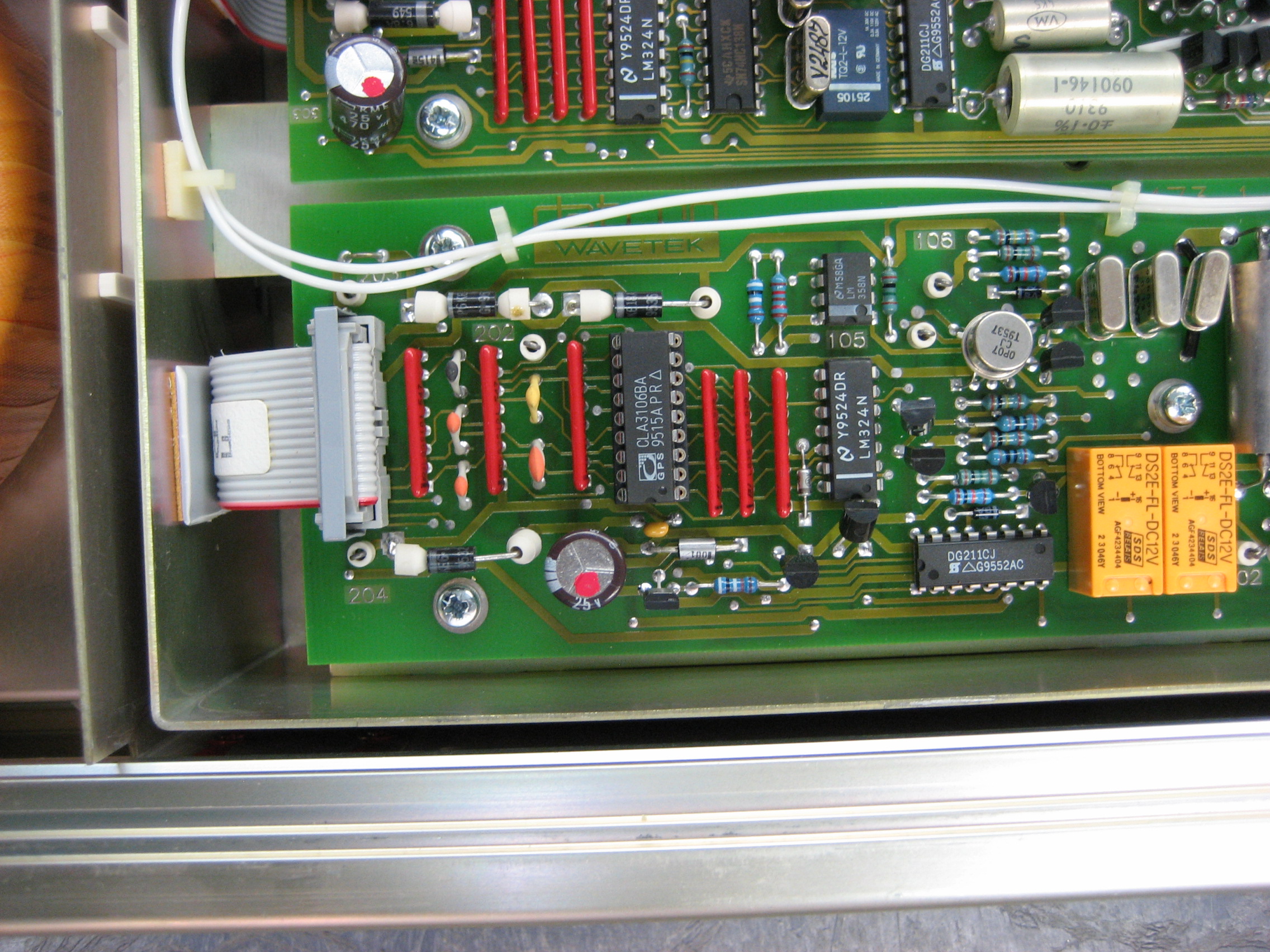
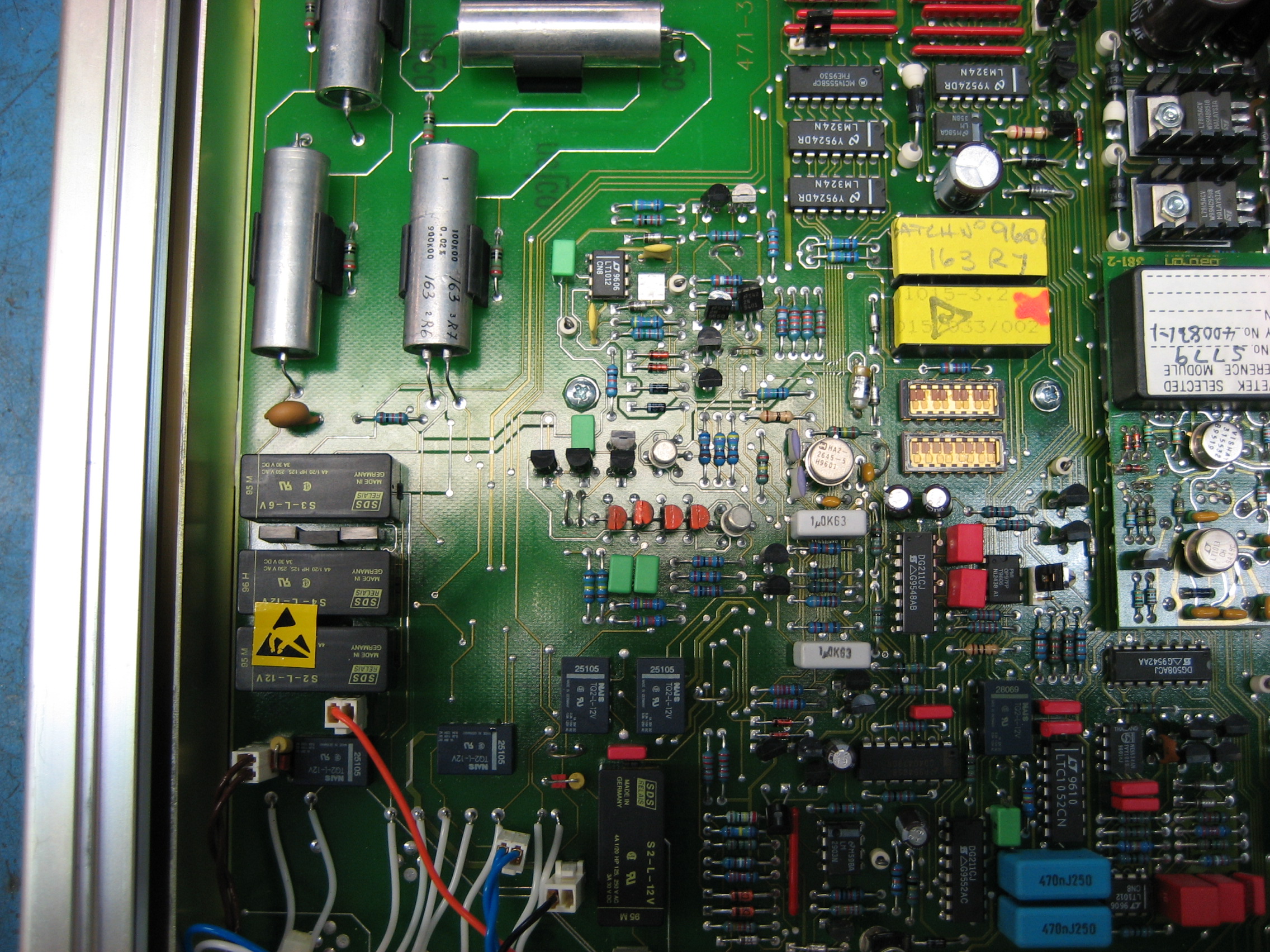
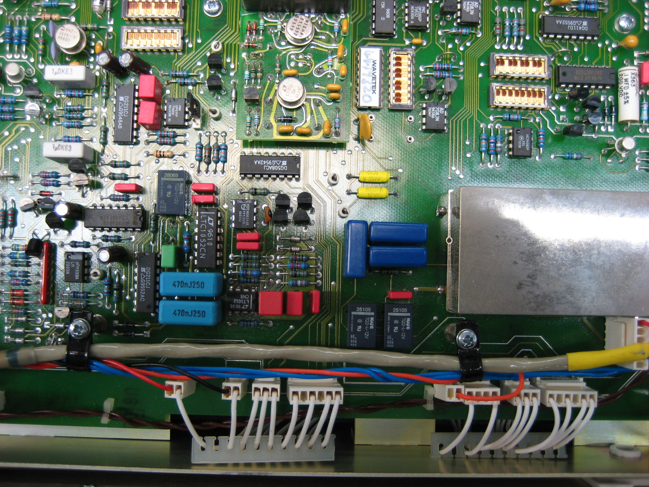
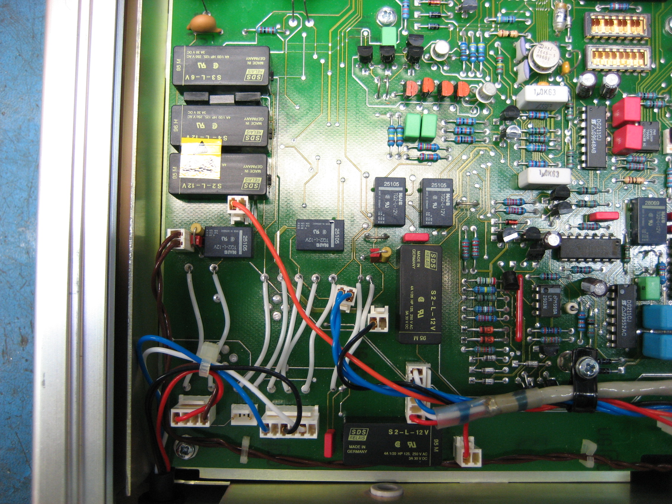
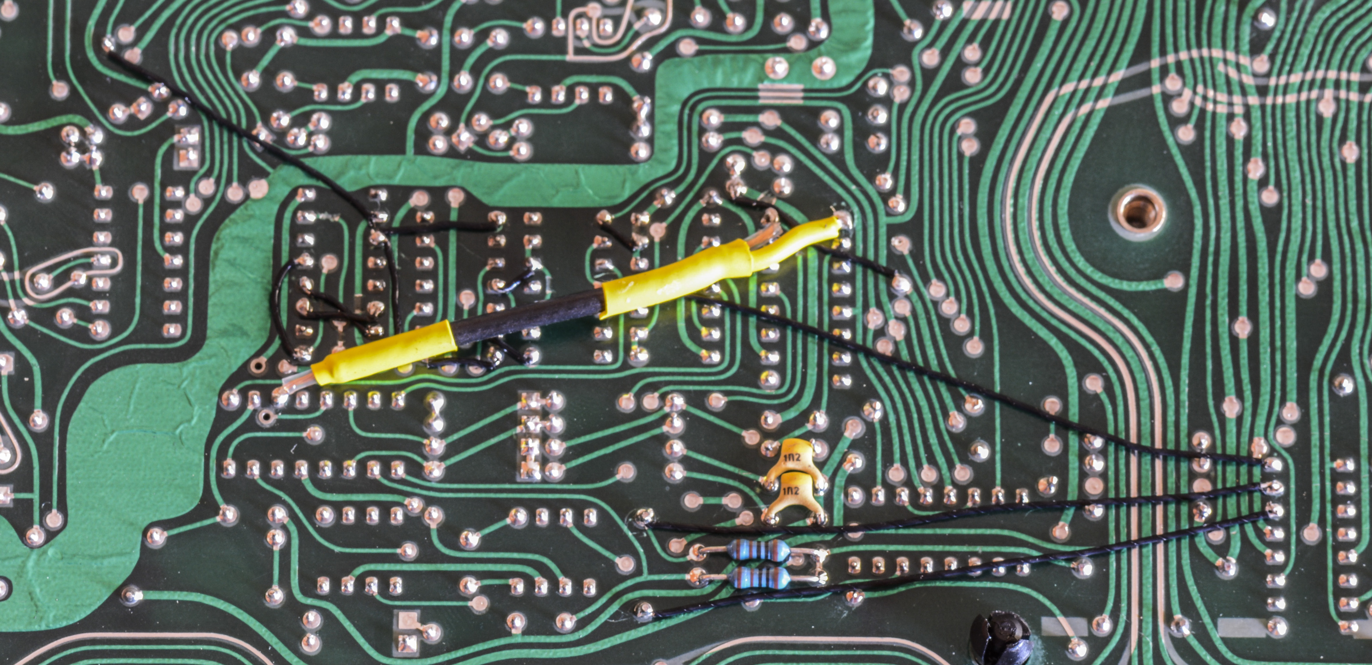
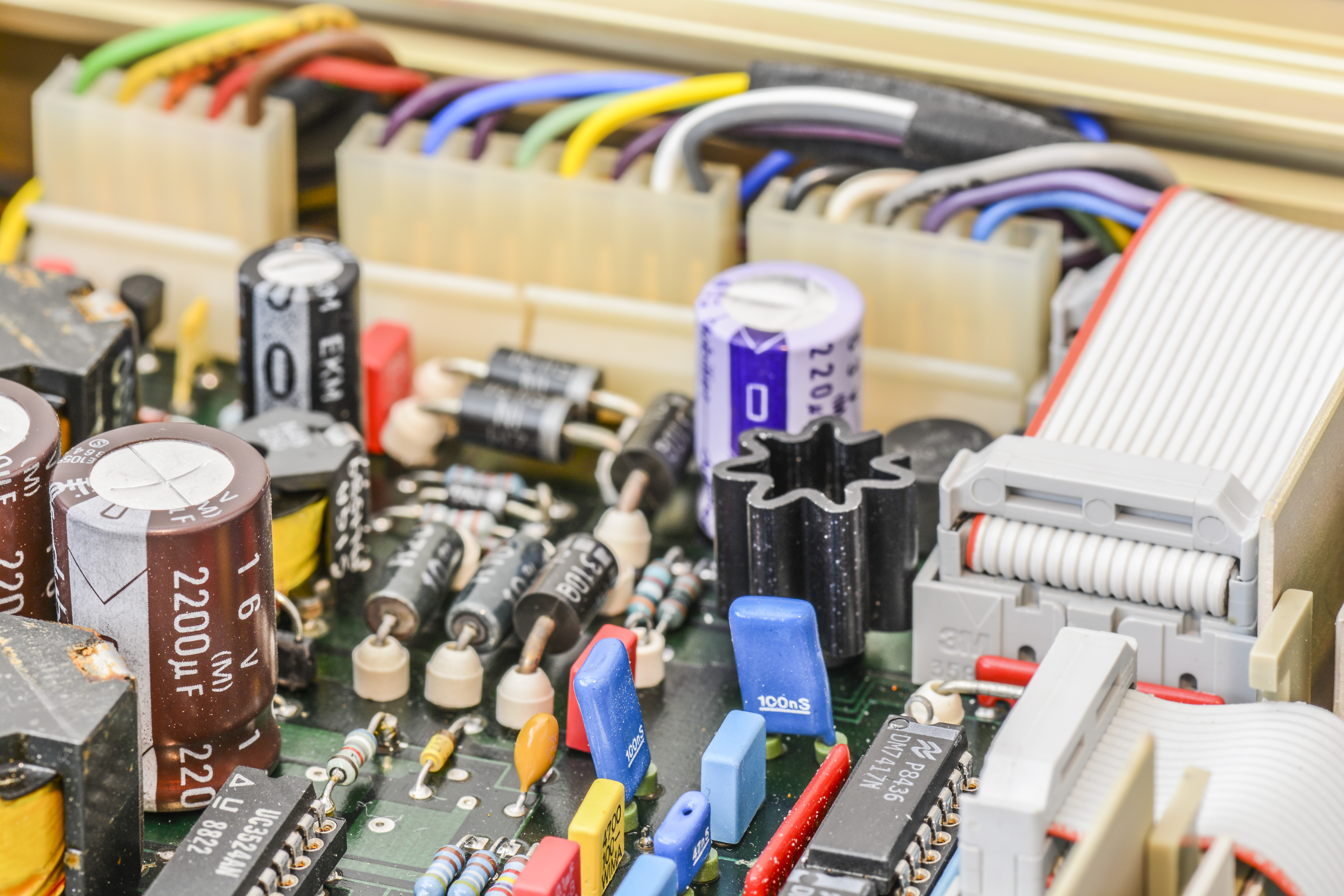
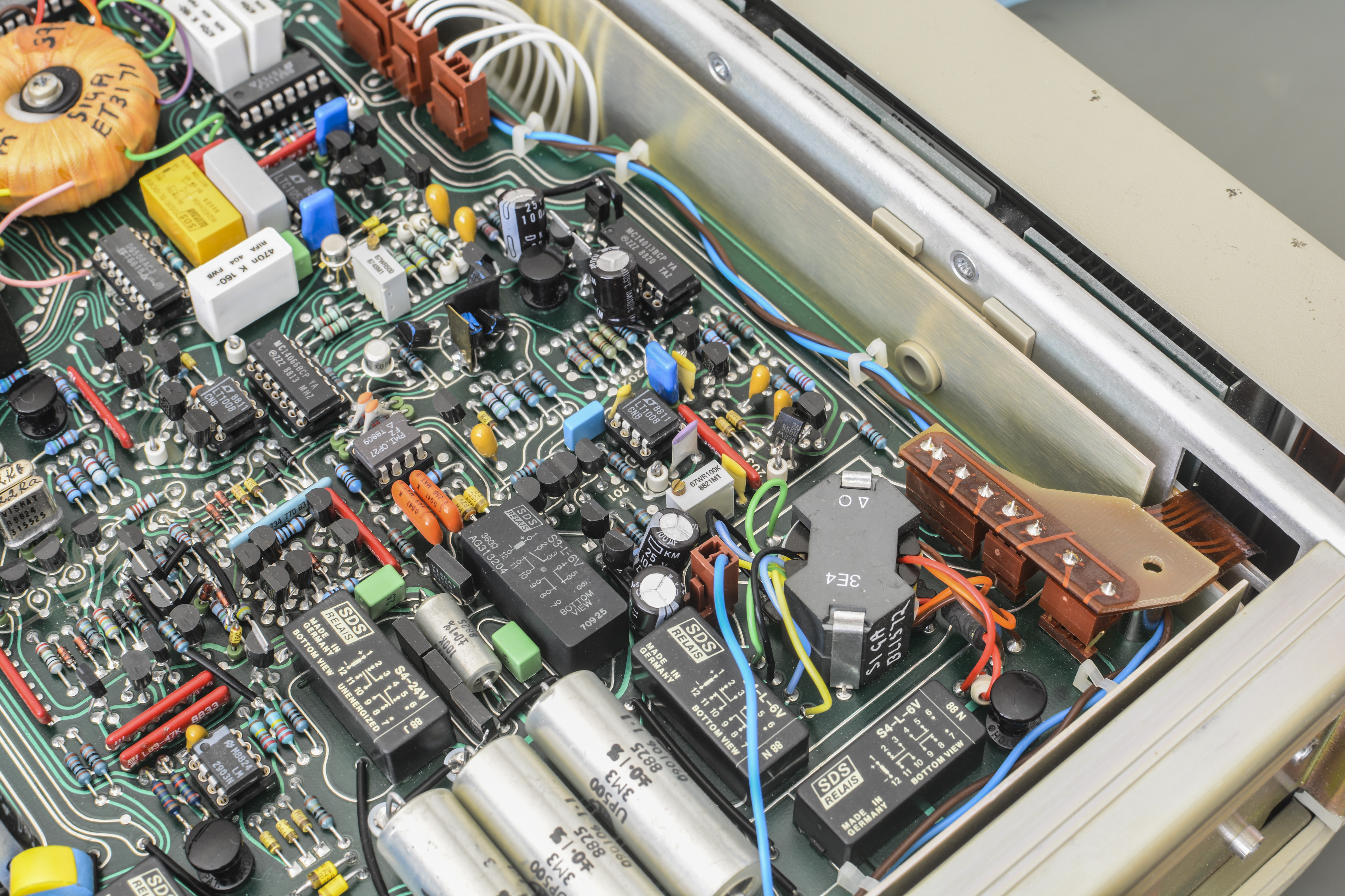
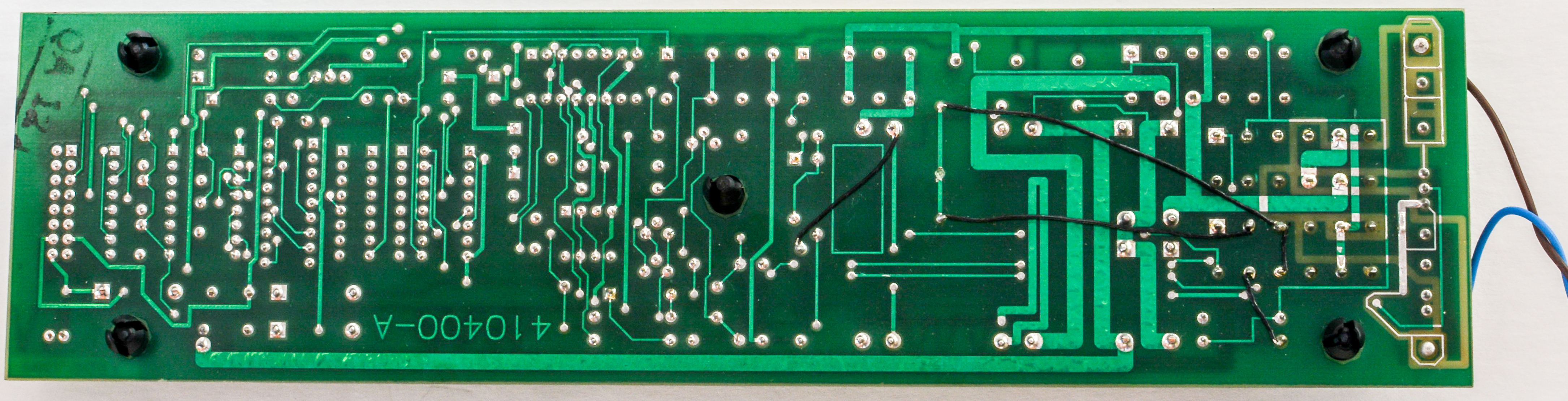
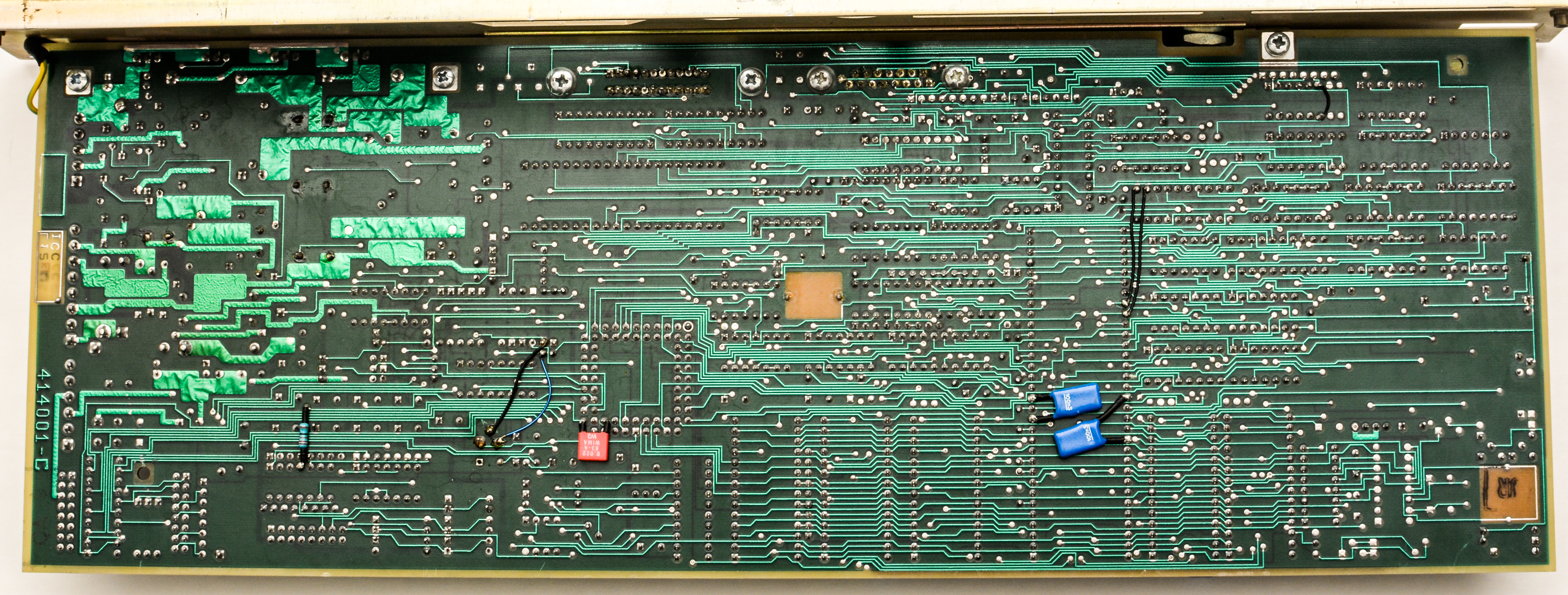
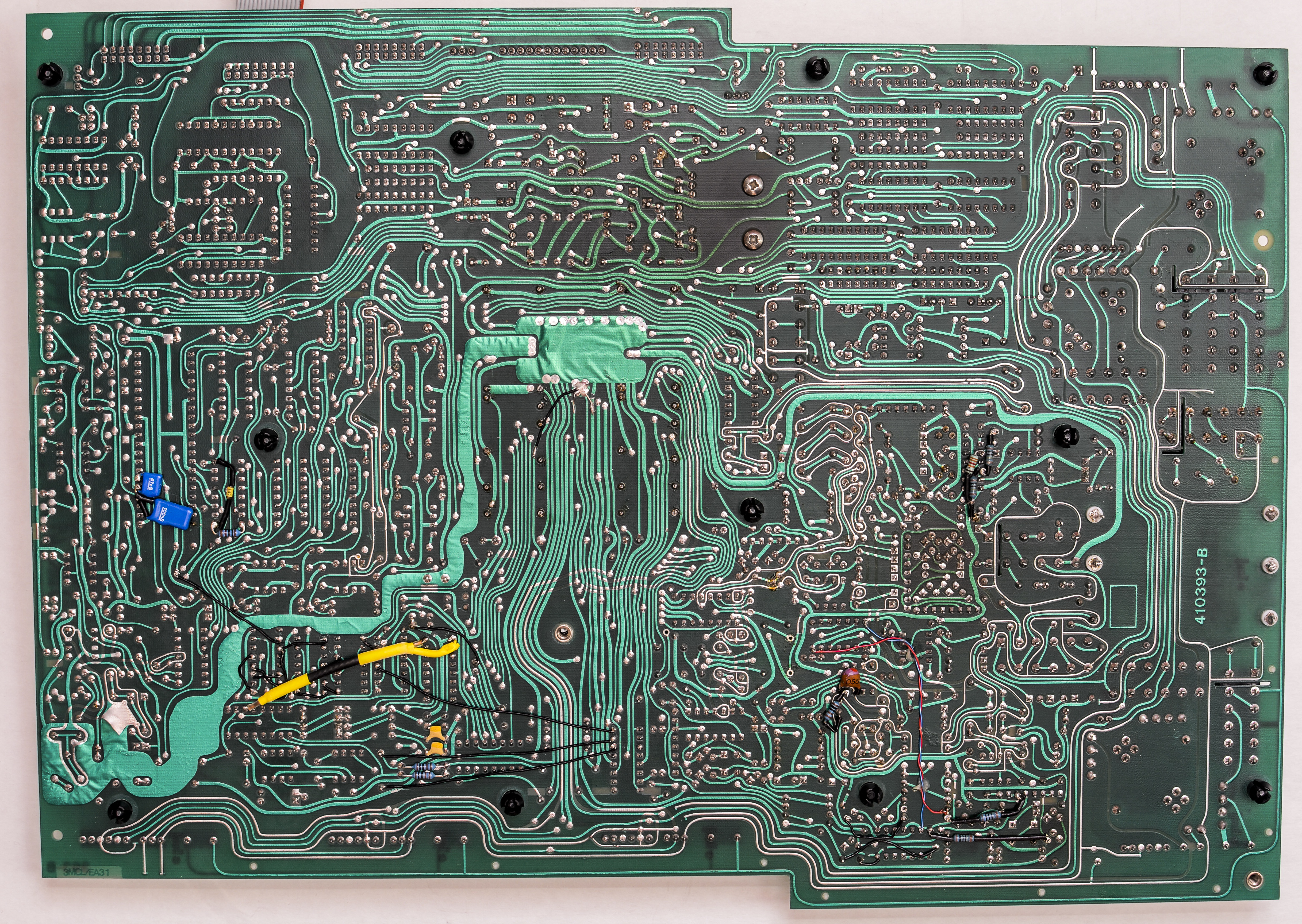
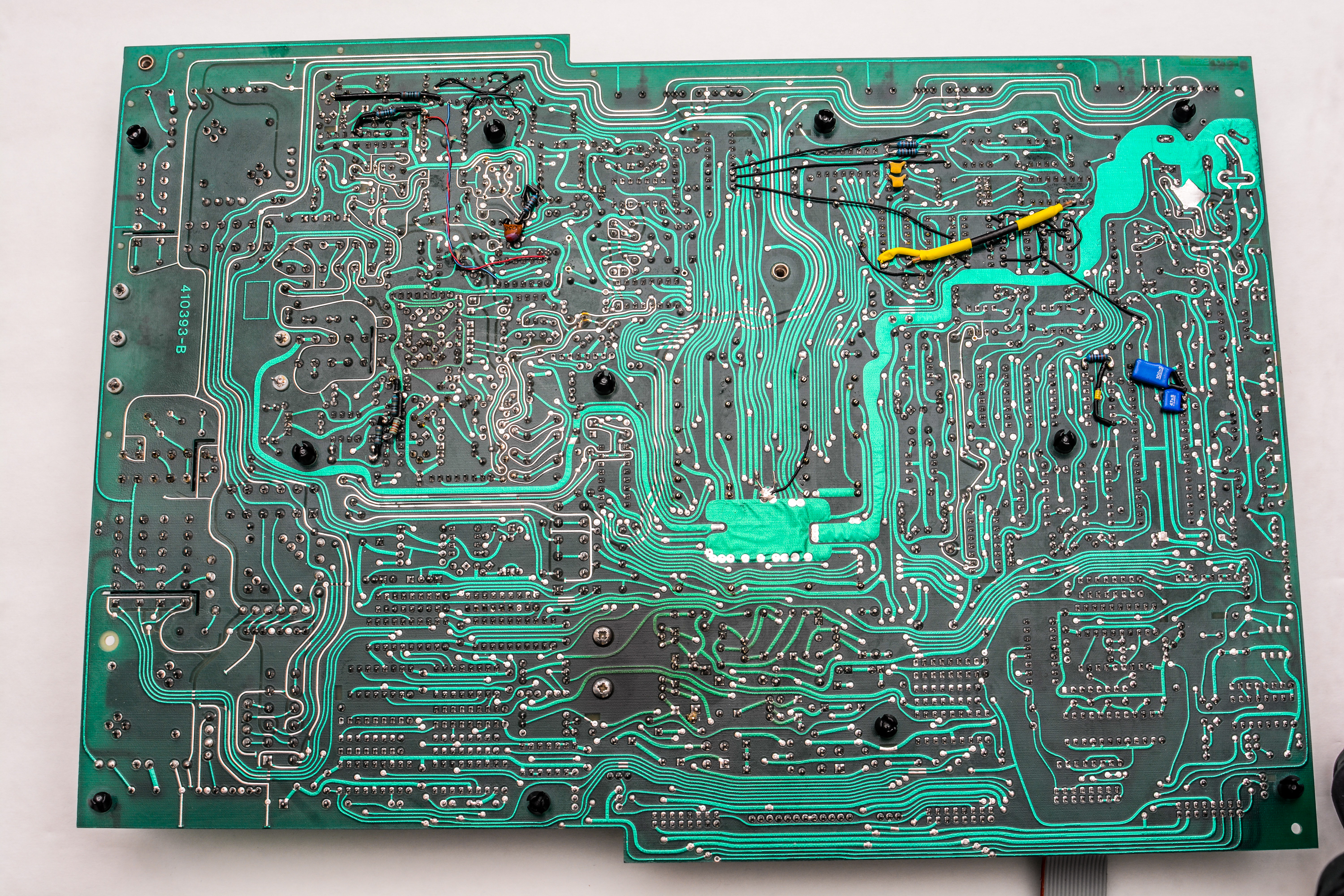
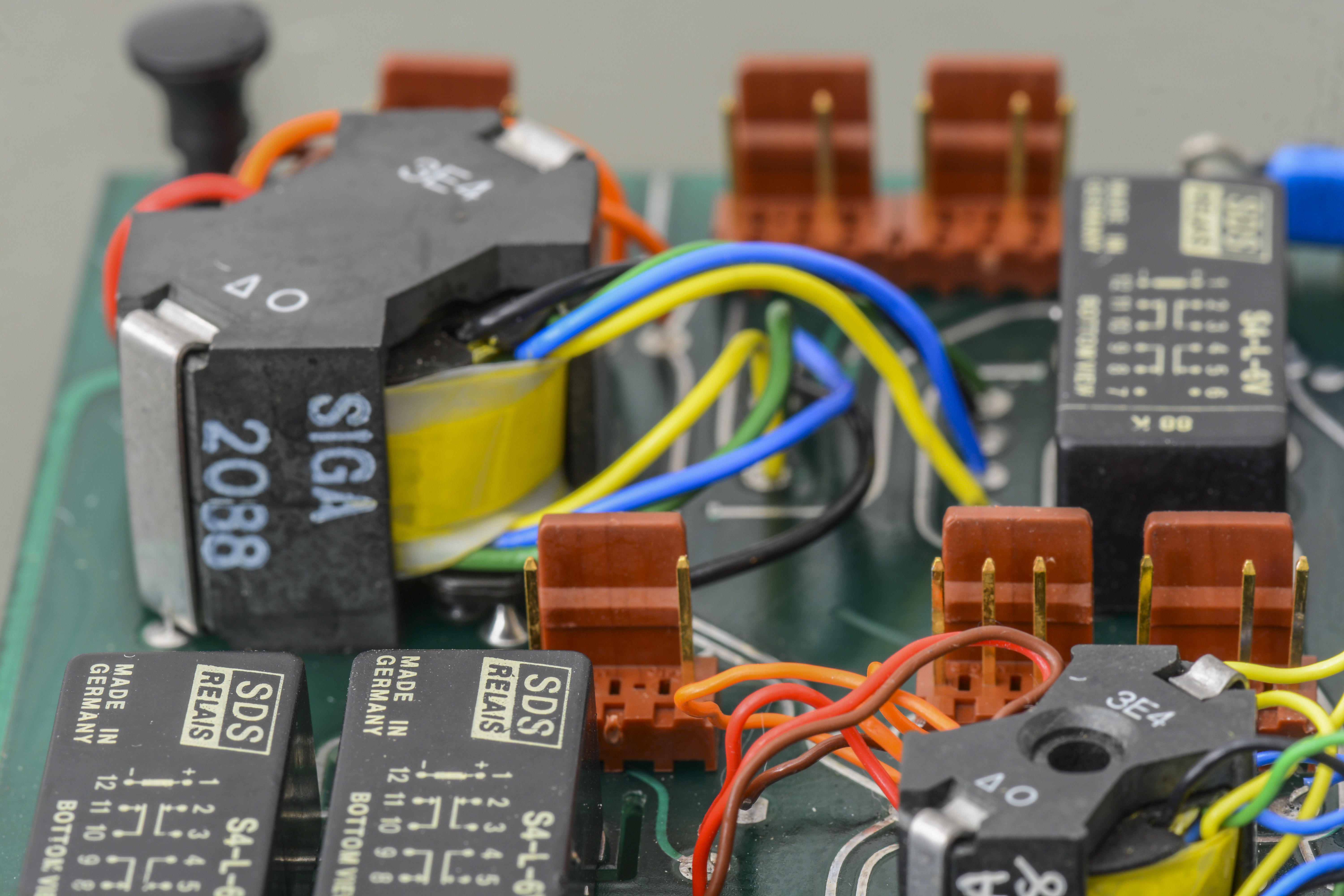
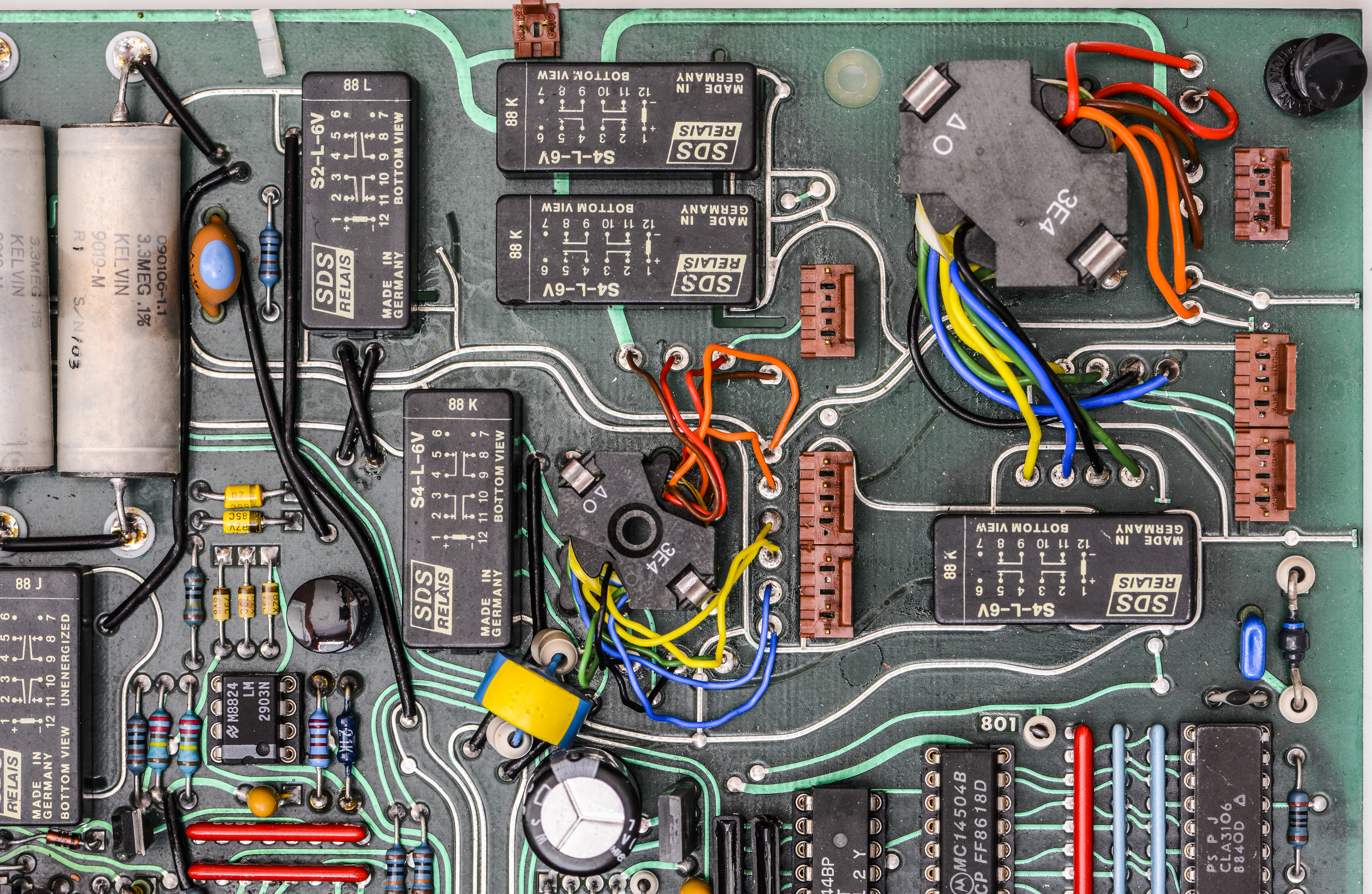
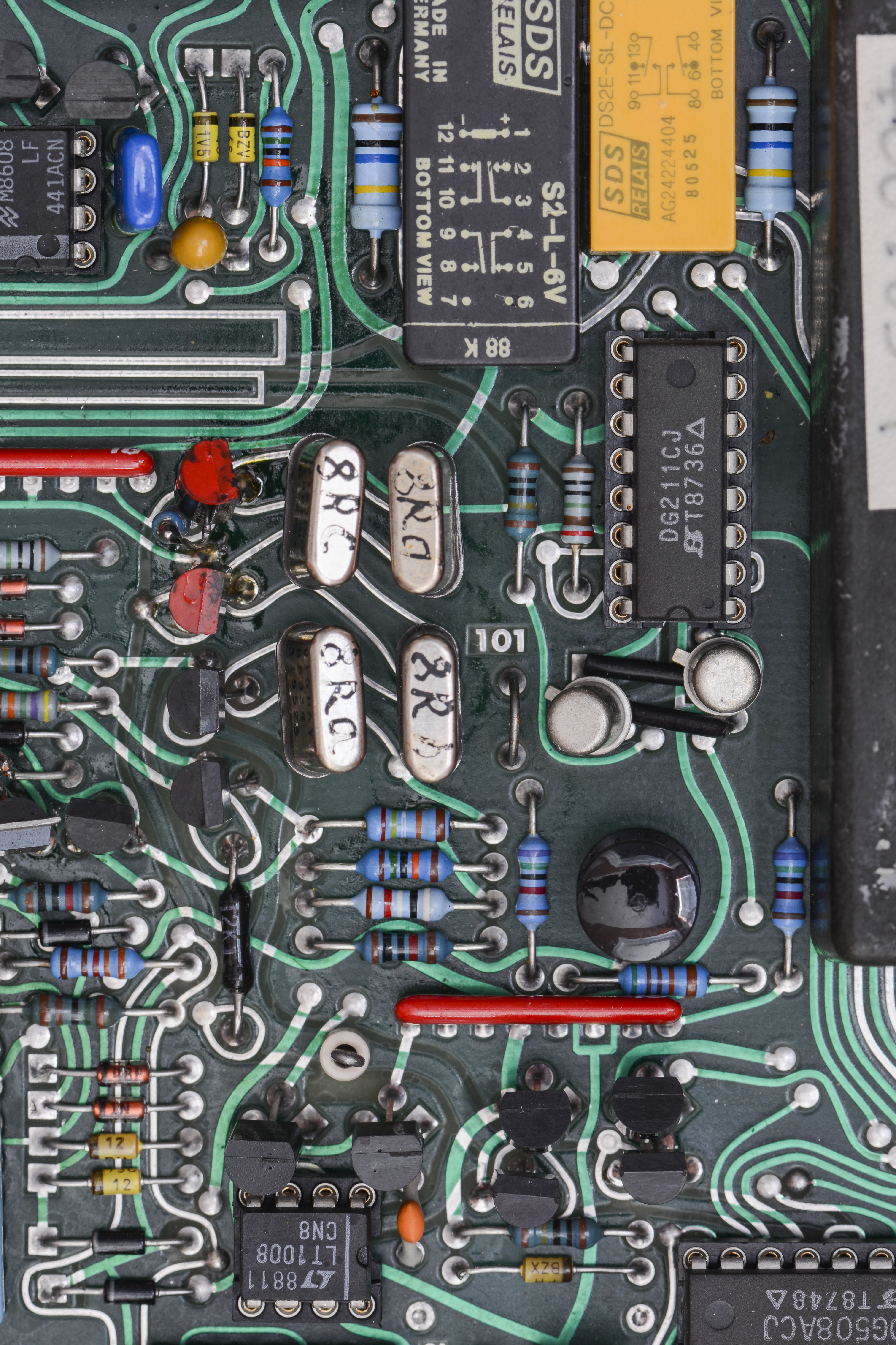
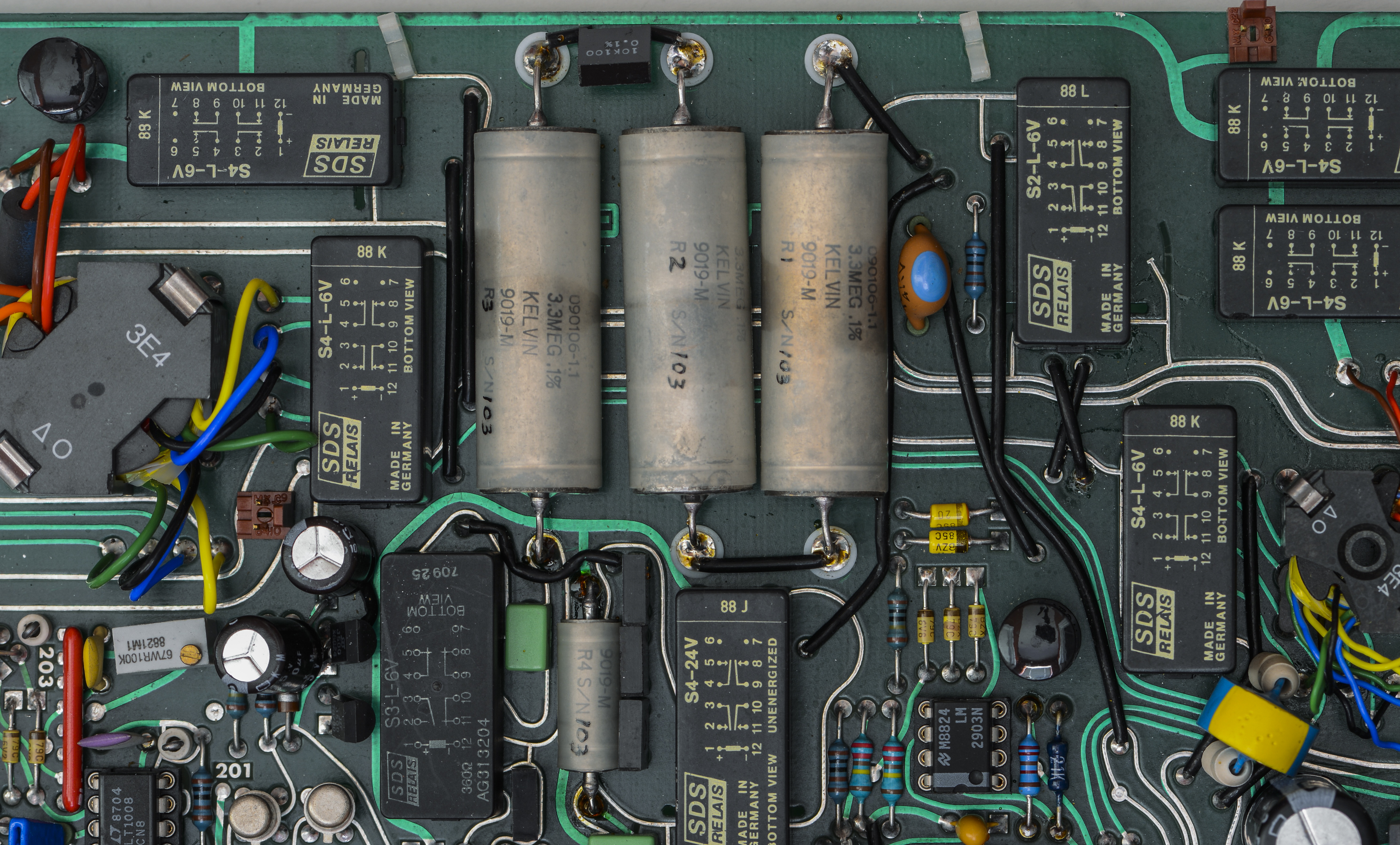
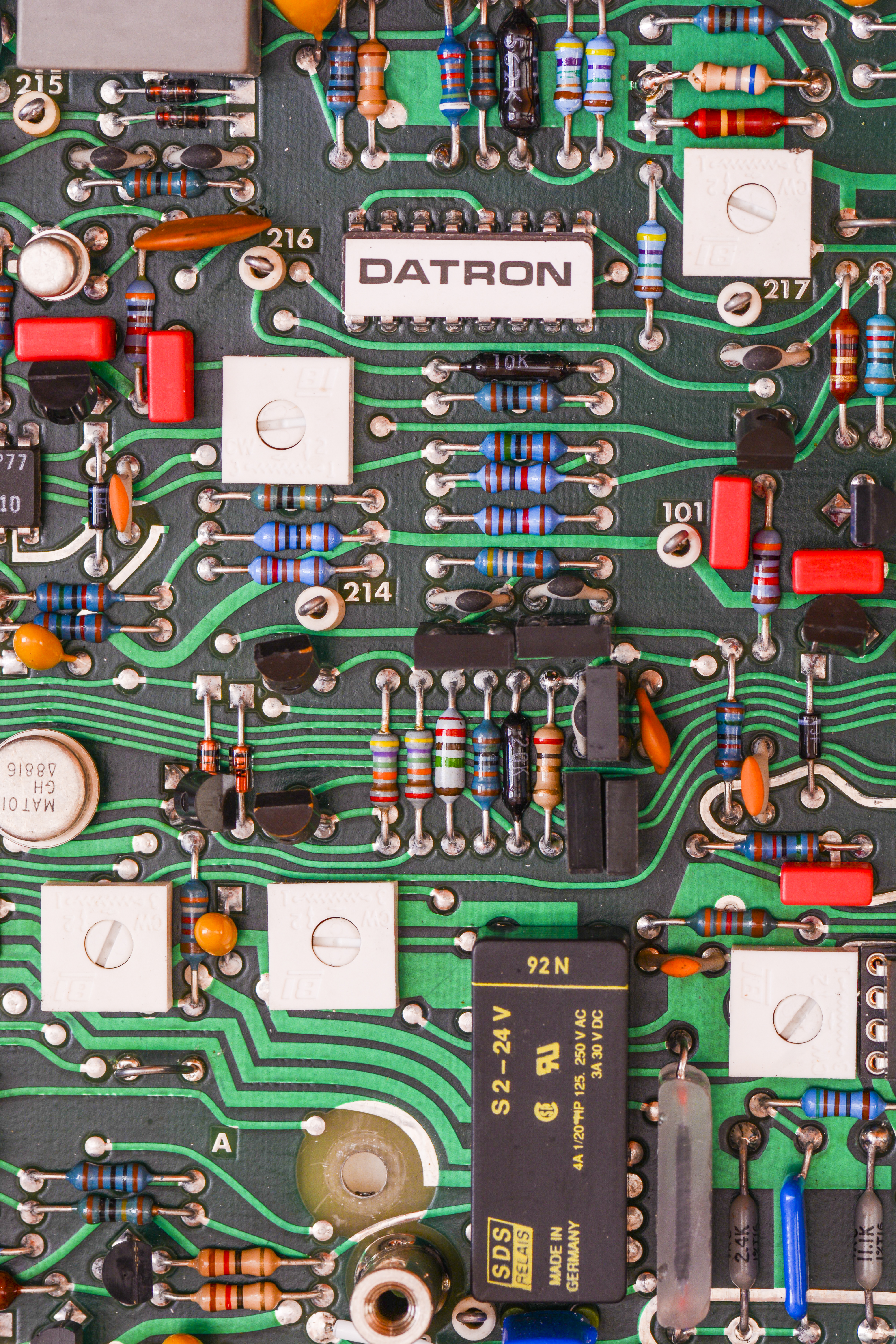
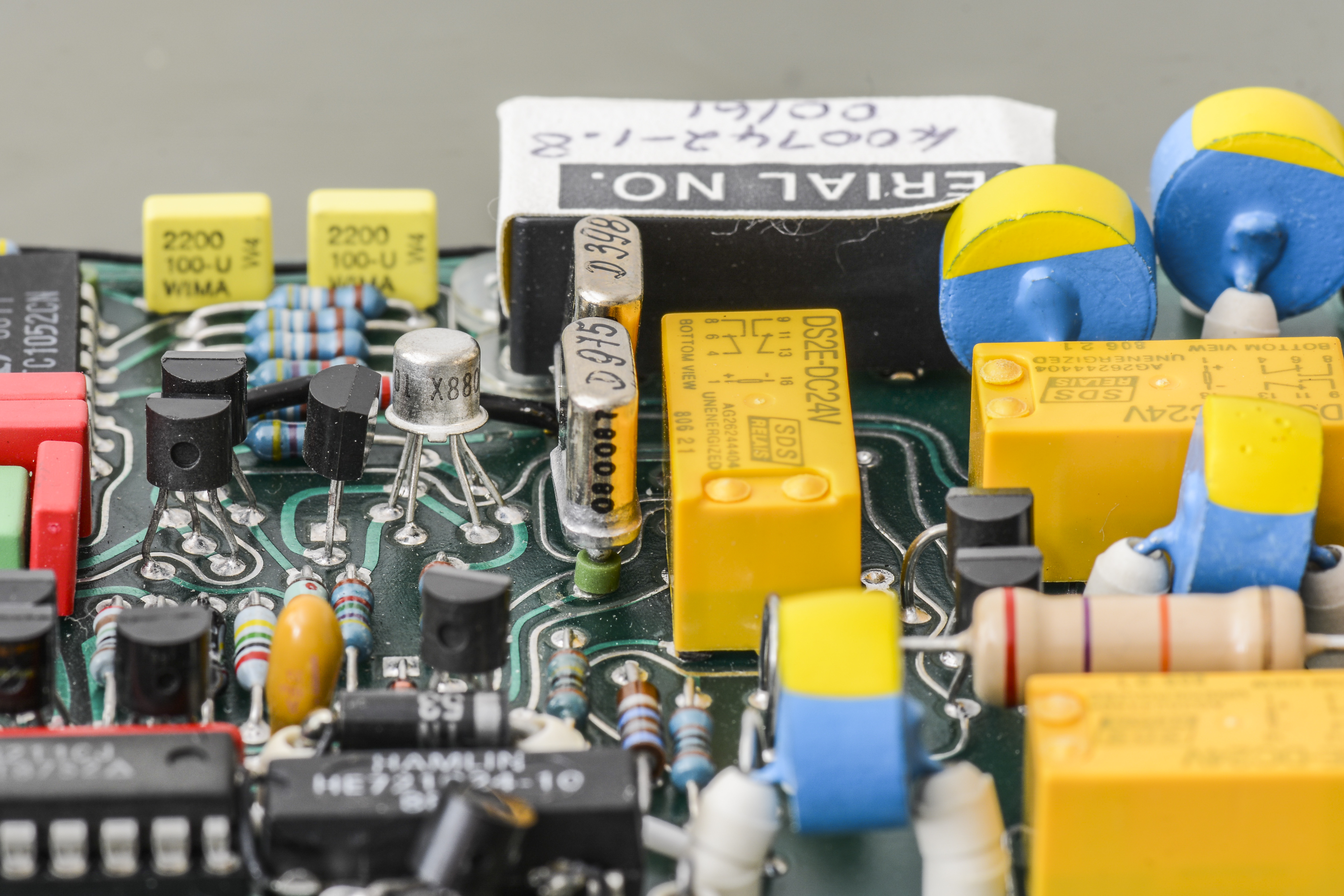
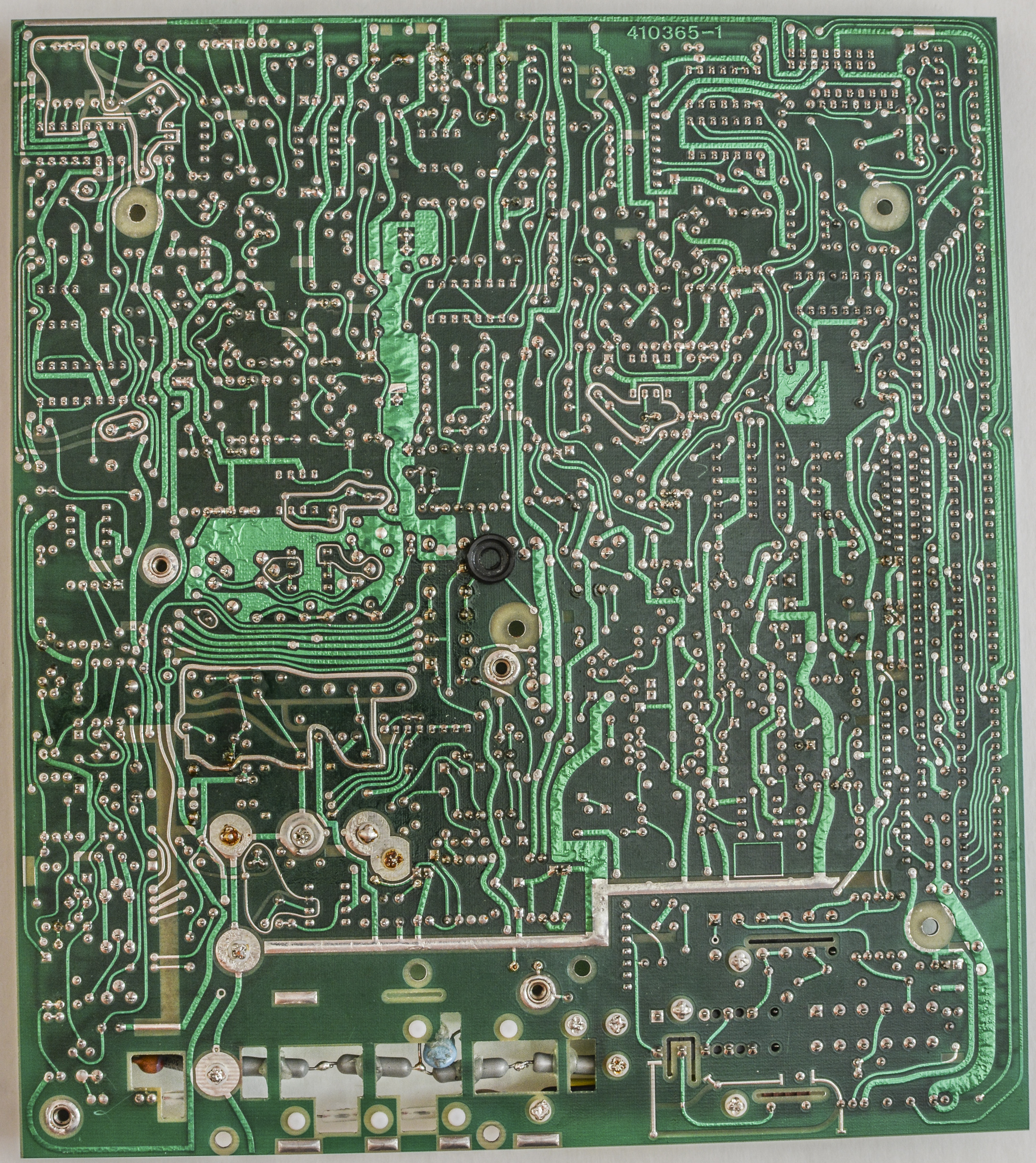
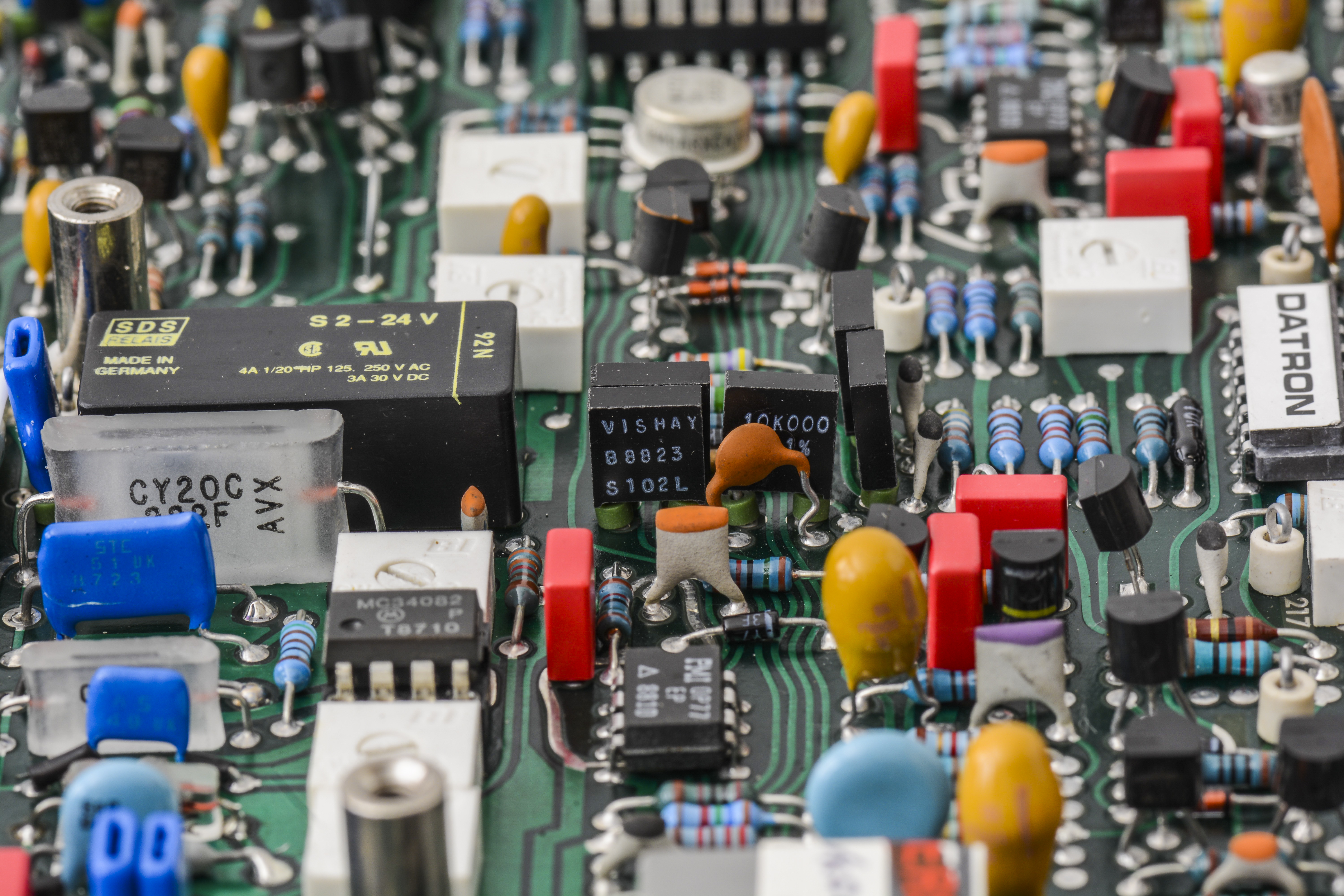
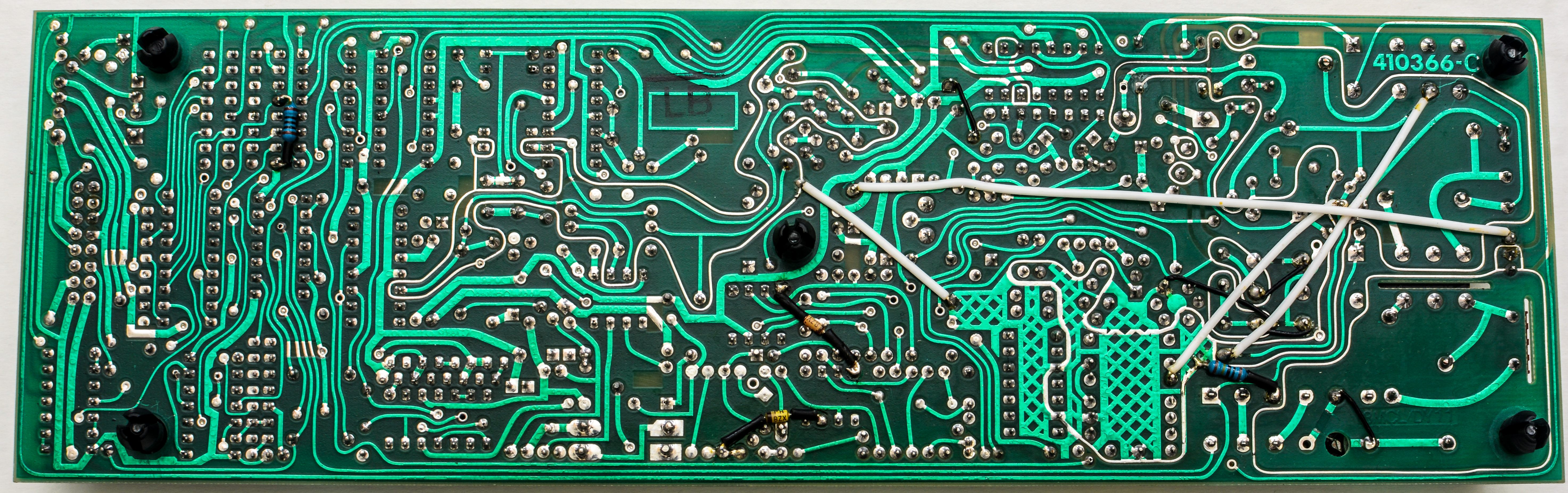
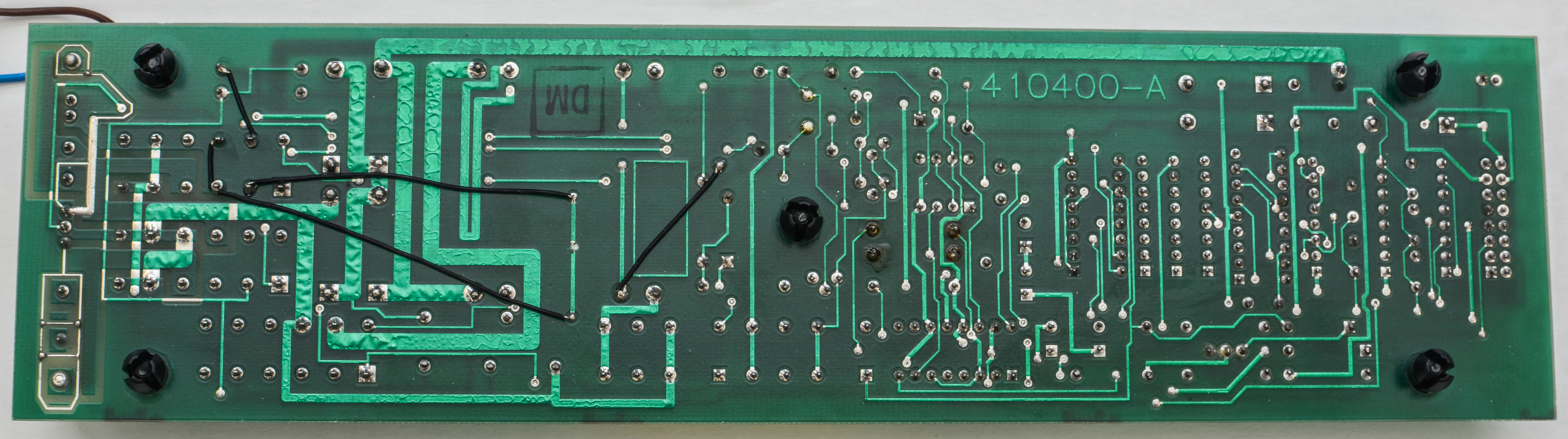
This board features same jump-wired reworks and patches on bottom side:

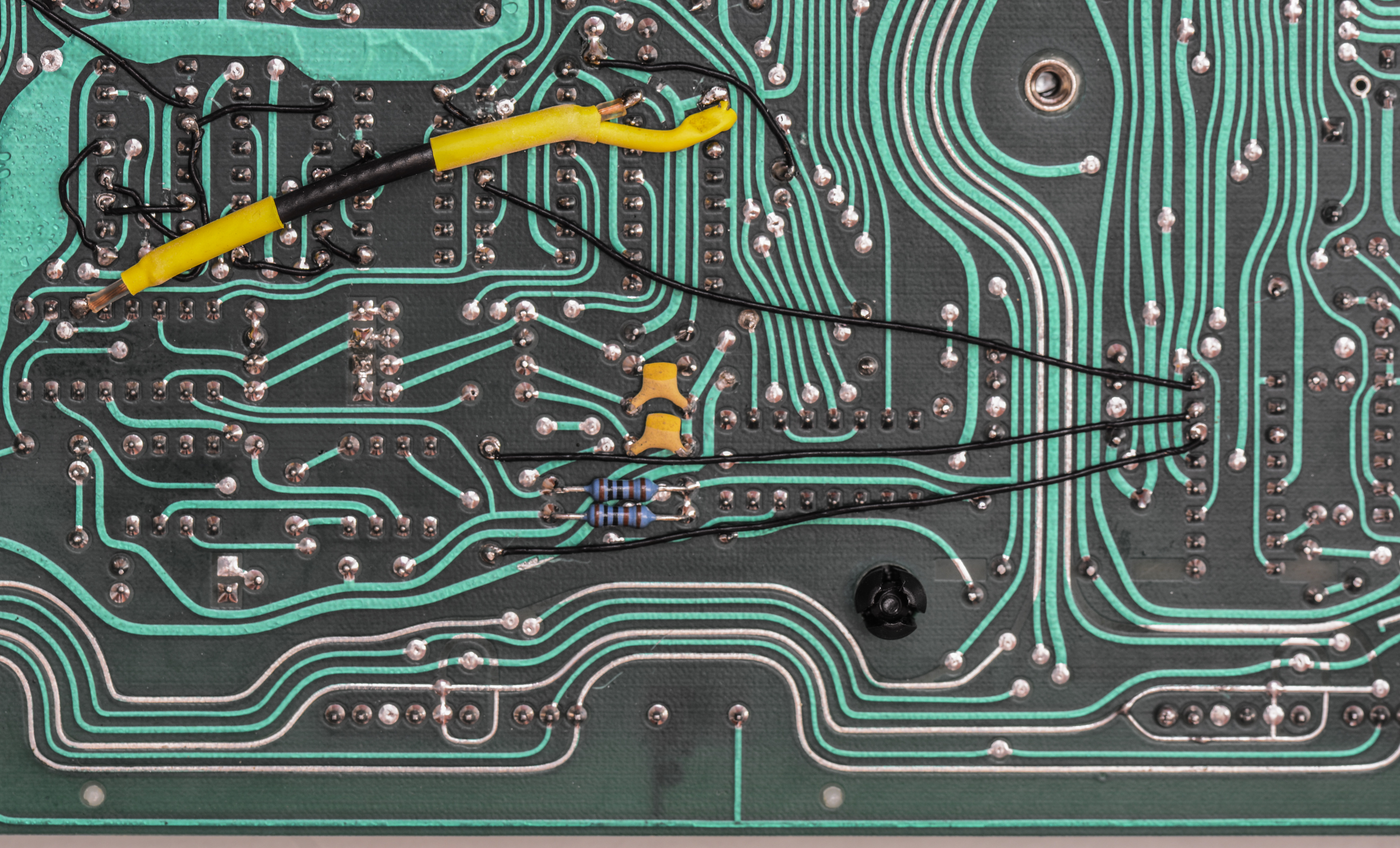
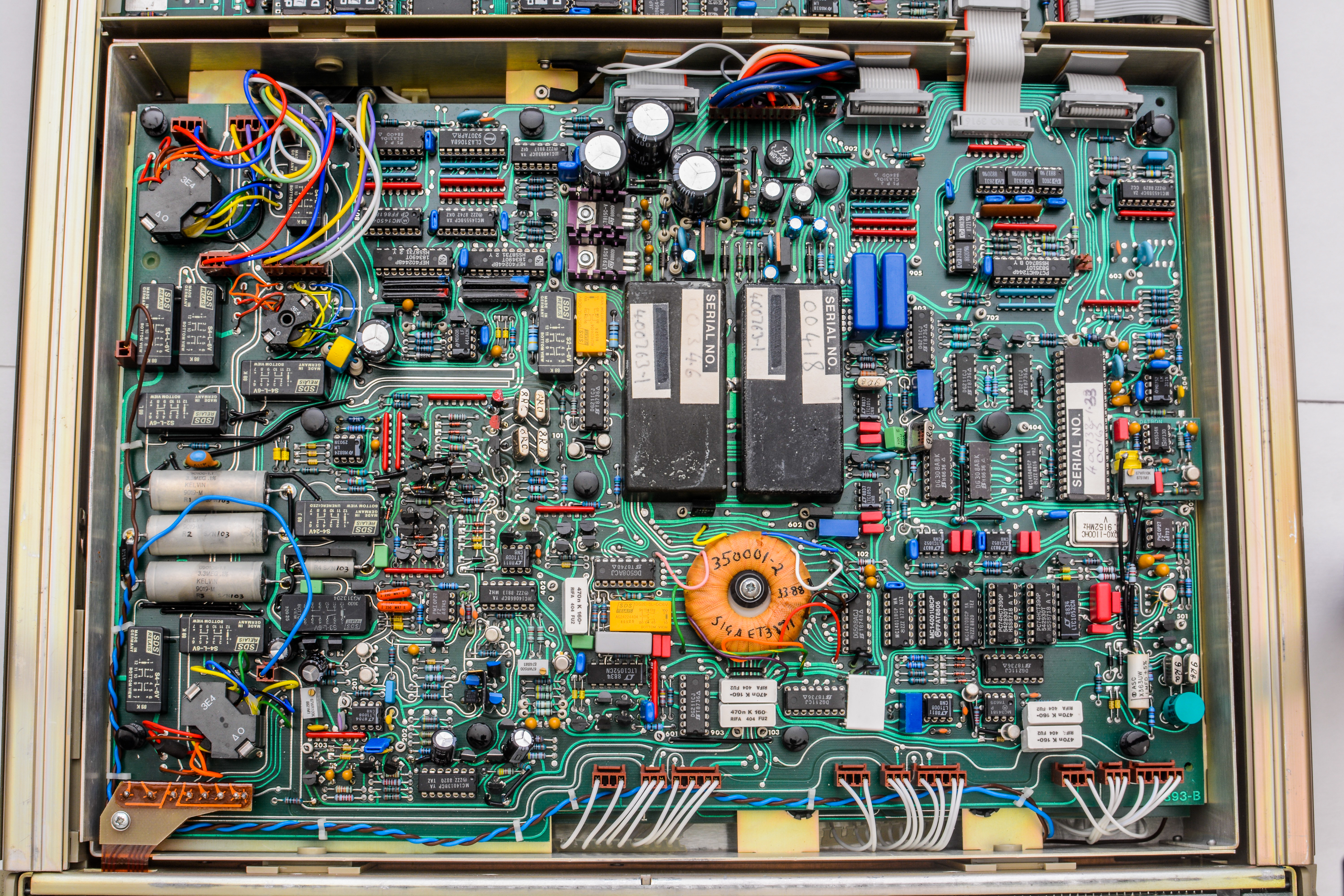

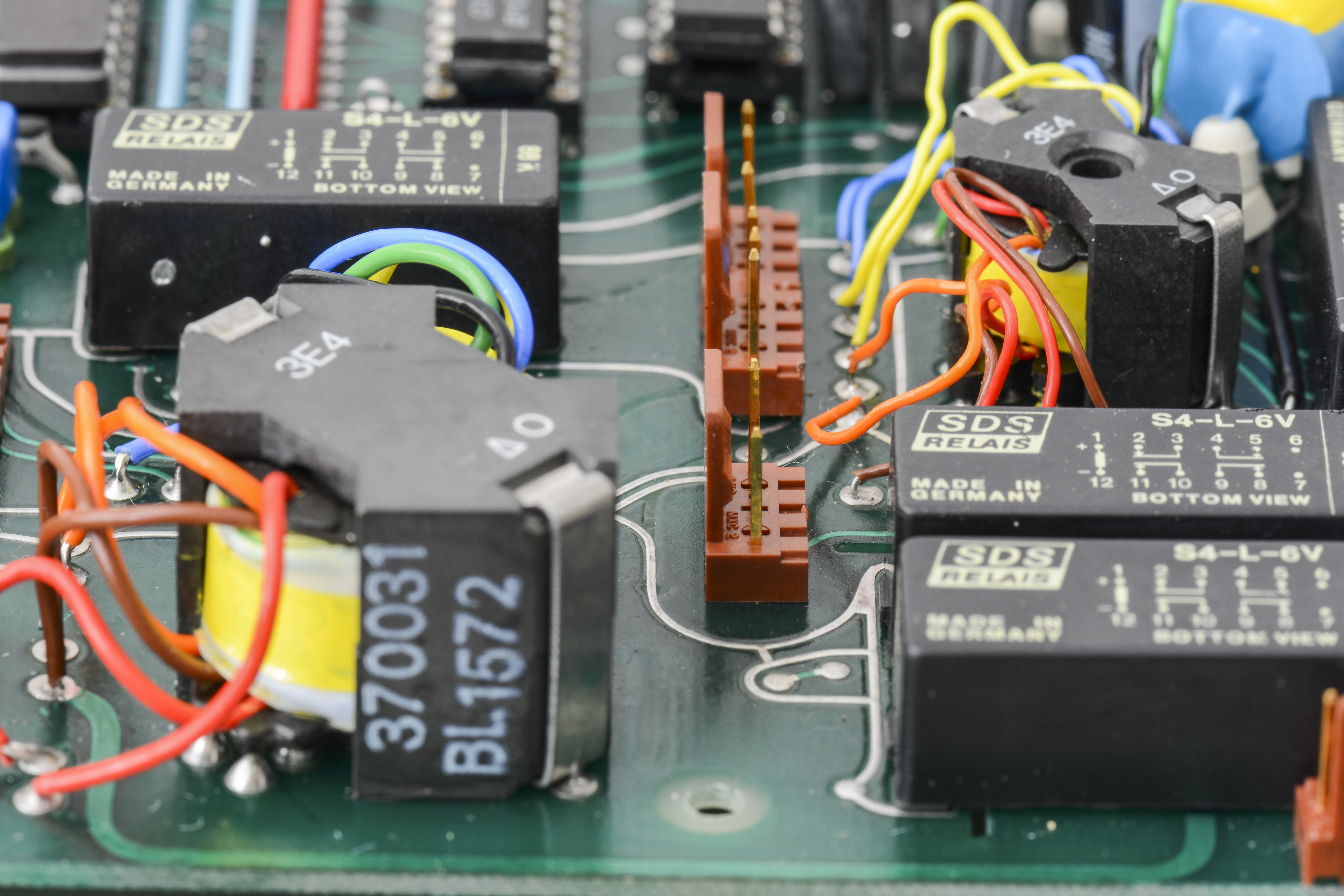
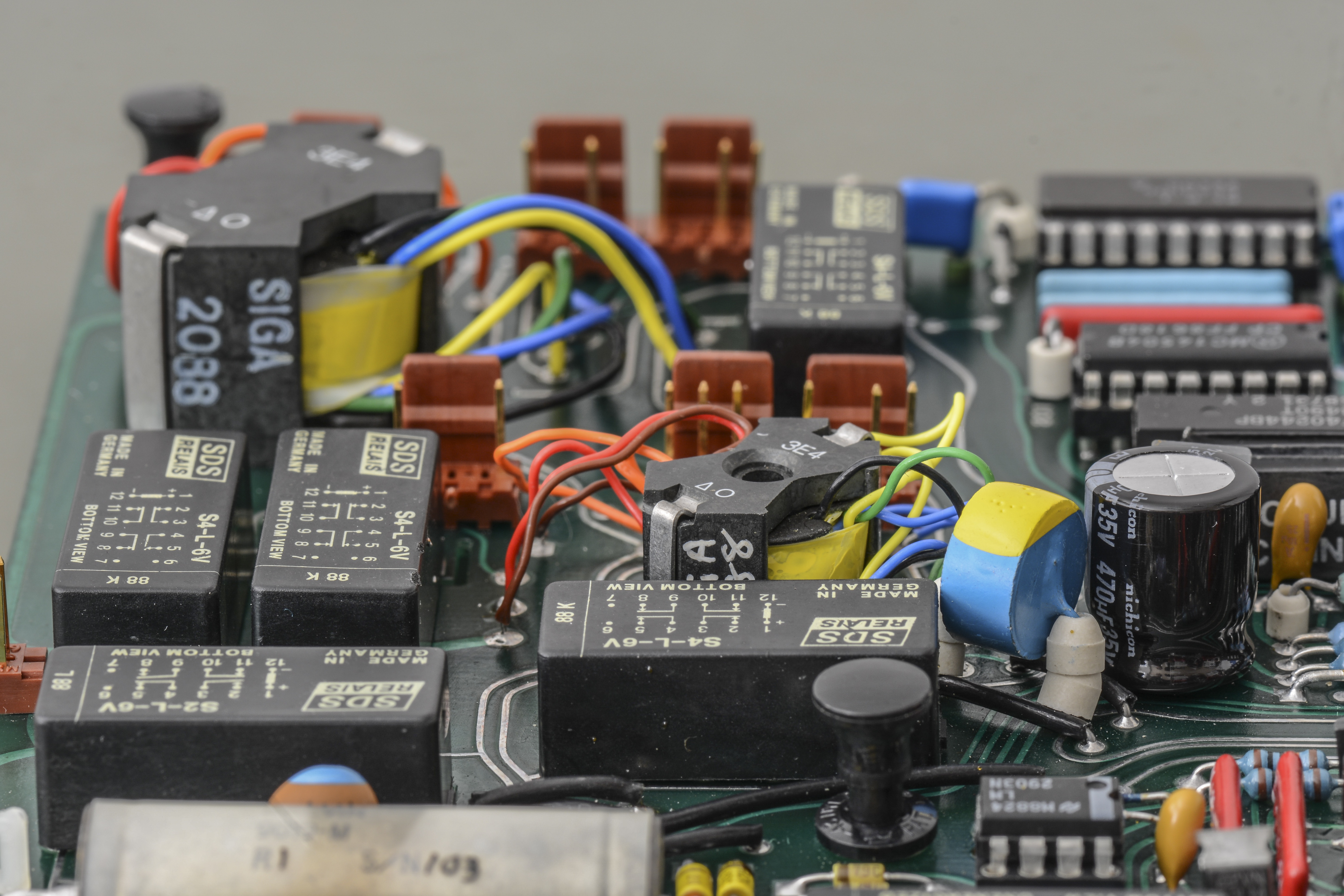
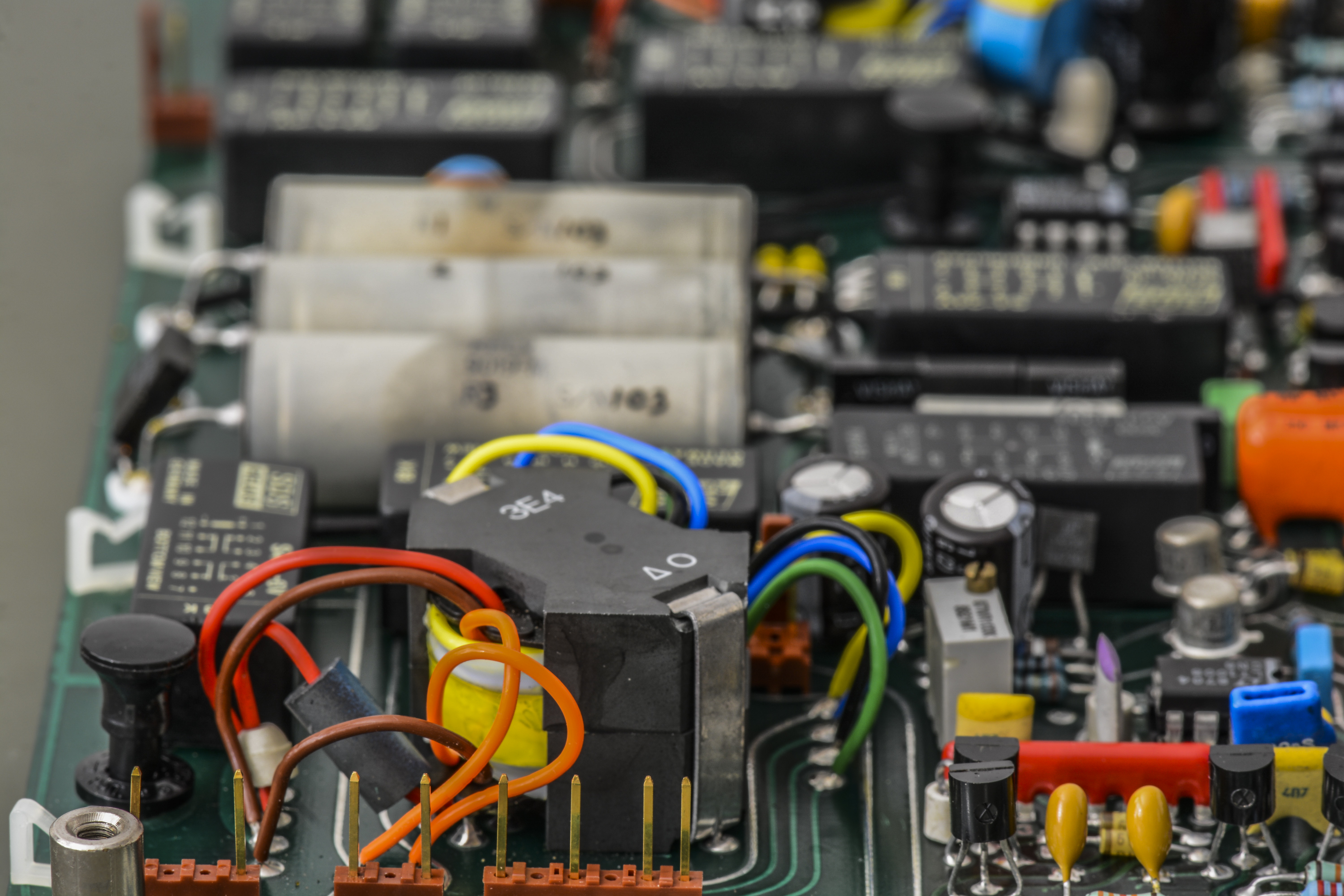
Looks at all those transformers!


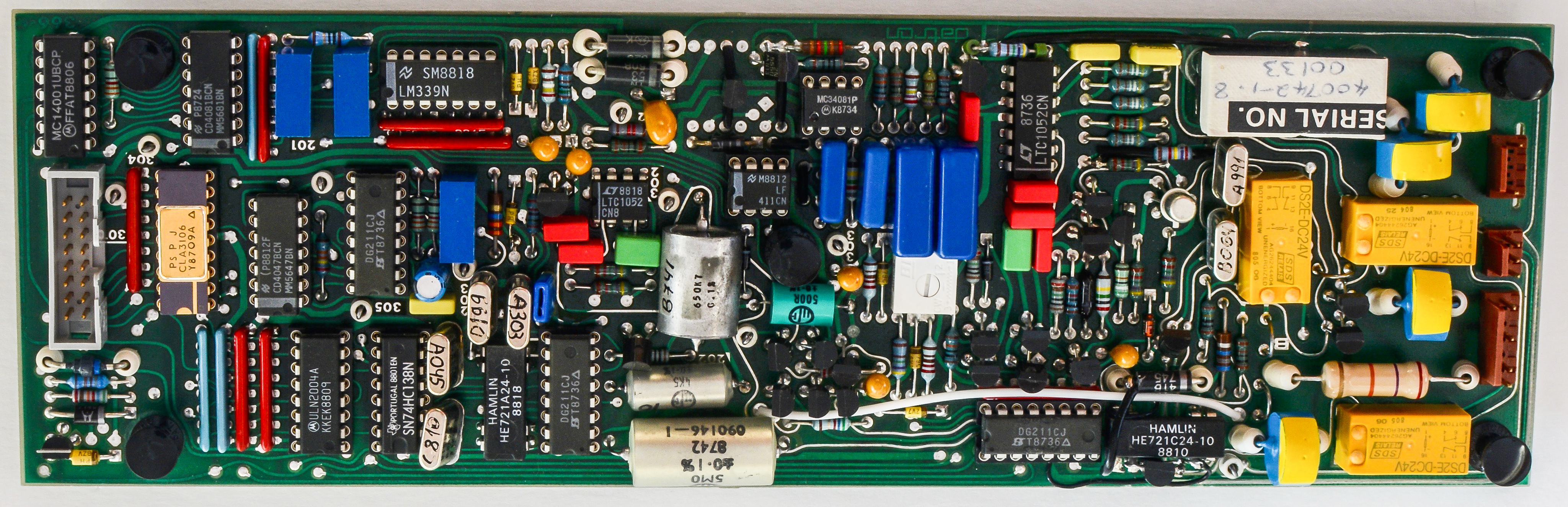
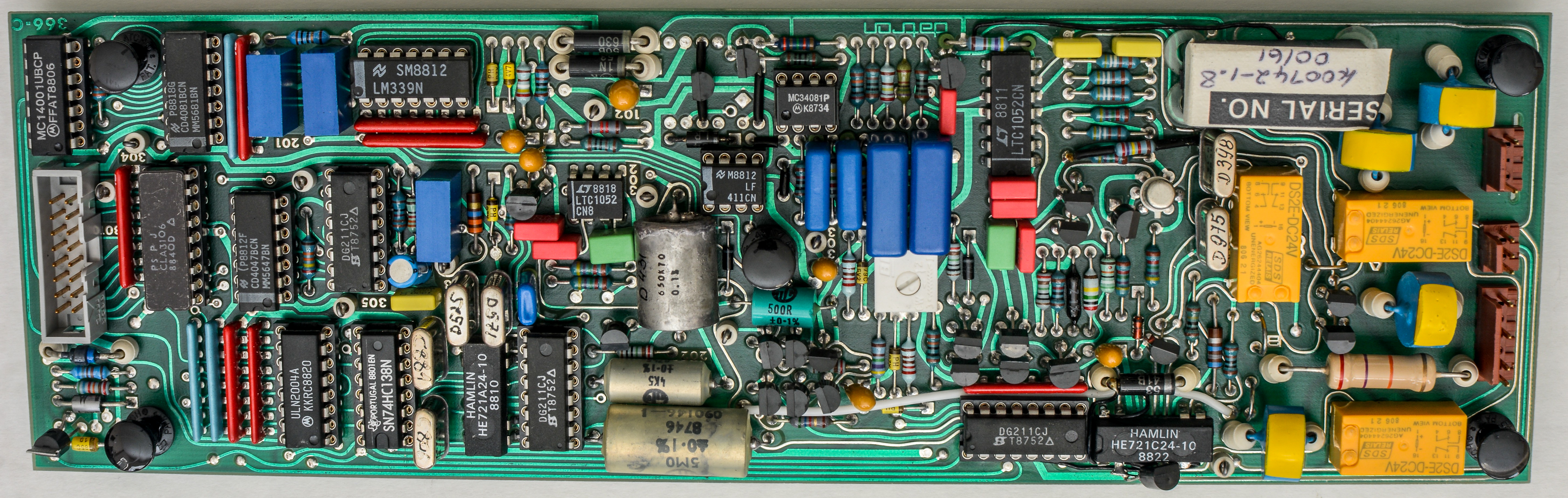
Option 10 – True RMS AC Converter

After capacitor replacement and reassembly meter throwing Error code 2512 : 1KV range which is related to AC board. Calibration on 100 mV DC range is off by ~2mV. It is measuring value through DC range, so it is a good possibility that offset on DCV measurement causing self-test for 2512 fail.
It appears that the diagnostic test for the failing step is low by 1.9 mVDC. It is supposed to be between 18.6 mV and 20.2 mV. I am reading 16.7 mV so gain loop of preamp is a little low or reference is low. Gain resistors were already measured and with shorted relay contacts to make sure they are working. Relays were also changed by previous owner so there must have been an “event” on the AC input side, which required repair/service of the unit. No signs of burning though.
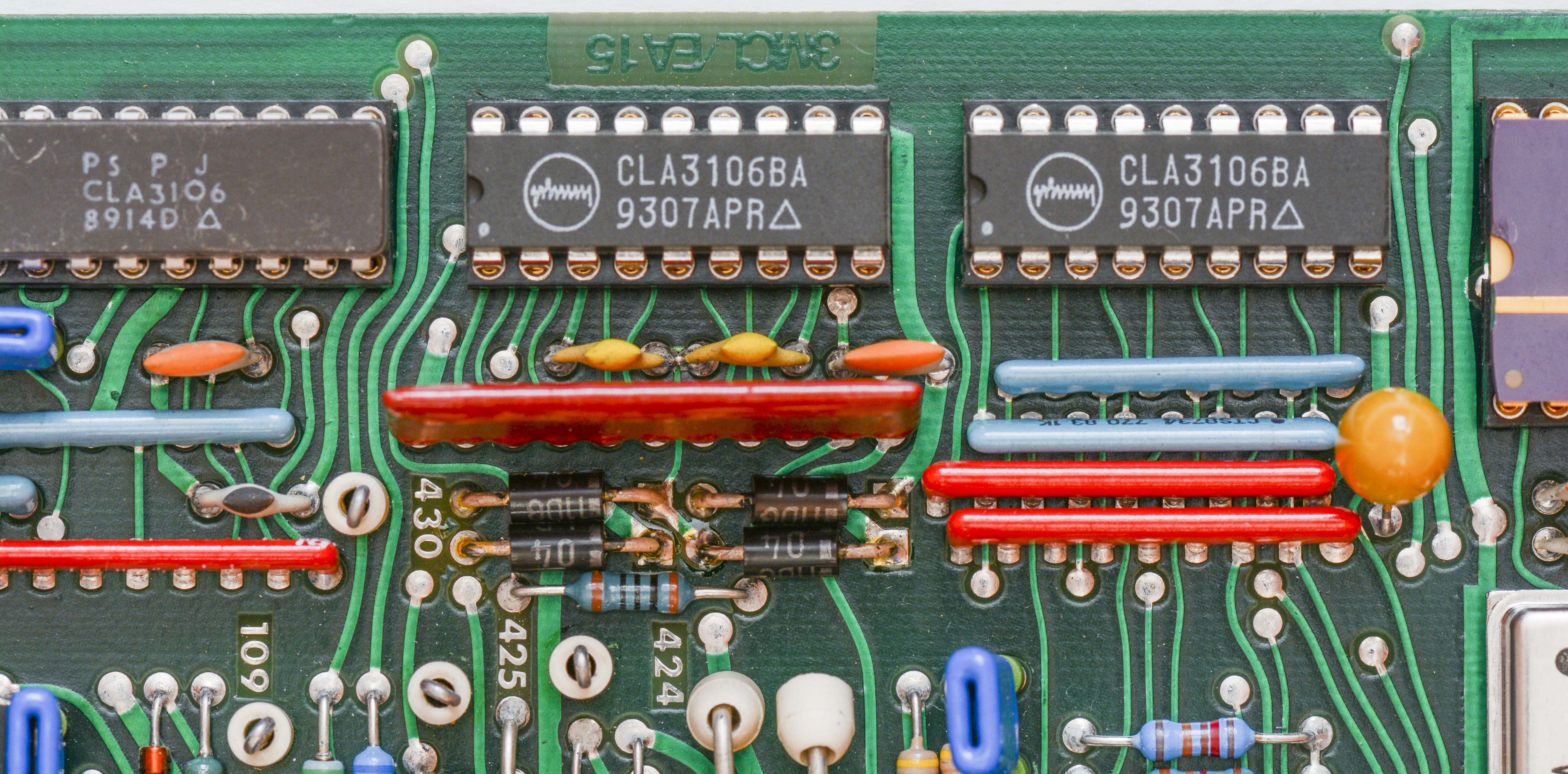
Error 2512 was added after repairing Digital and DC assys. After going over all cable connections nothing obvious was found. However, after closer inspection, it was discovered that a couple of parts had been replaced sometime back in 1993. A couple of Mitel CLA parts and some reed relays all indicated that the AC assy had failed around that time. It also agrees with the EPROM firmware date codes.
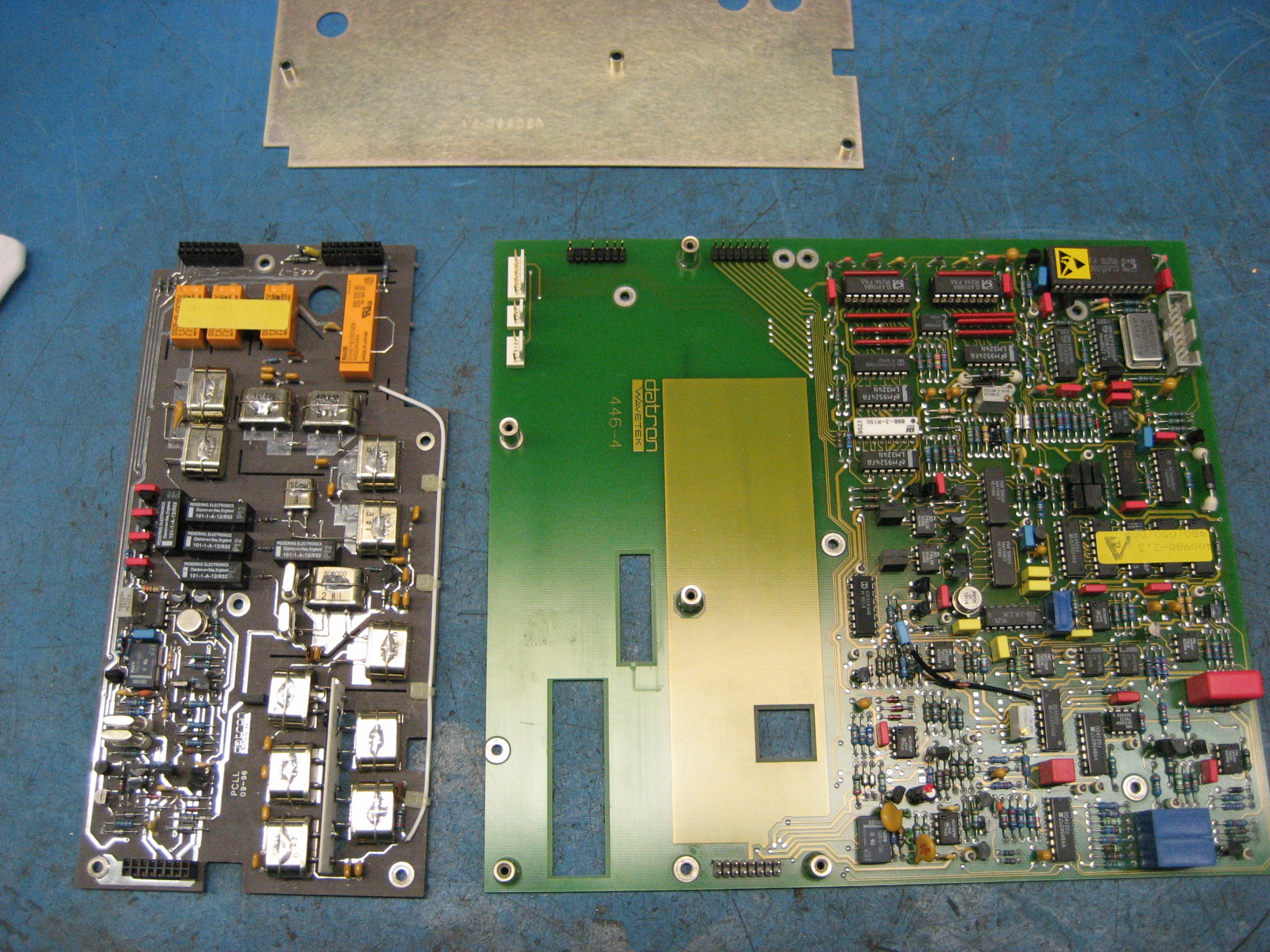
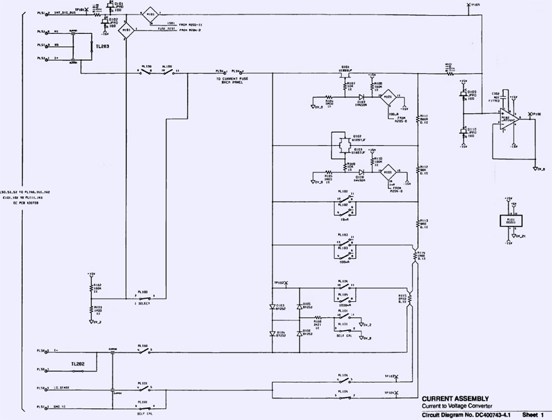
The service manual includes diagrams of the circuit board parts involved with specific tests. It is also separated between the full or fast self-test. The “pathway” codes are included as well as how to select them. P076 is the pathway for test 2512. After recording several different pathway readings of full and fast tests, it was was the only test that was failing. The board was removed and inspected closer under magnification. A few solder joints on the board were suspicious and reflowed. The relays involved with the 10/100/1kV range preamp were reflowed as were the range resistors. It was also found that a plastic spacer that sits between the board and one of the standoffs was no longer in place. After cleaning a large amount of flux residue from the surface of the board, it was reinstalled and retested. All errors were now gone and a fast looptest passed after 24 iterations.

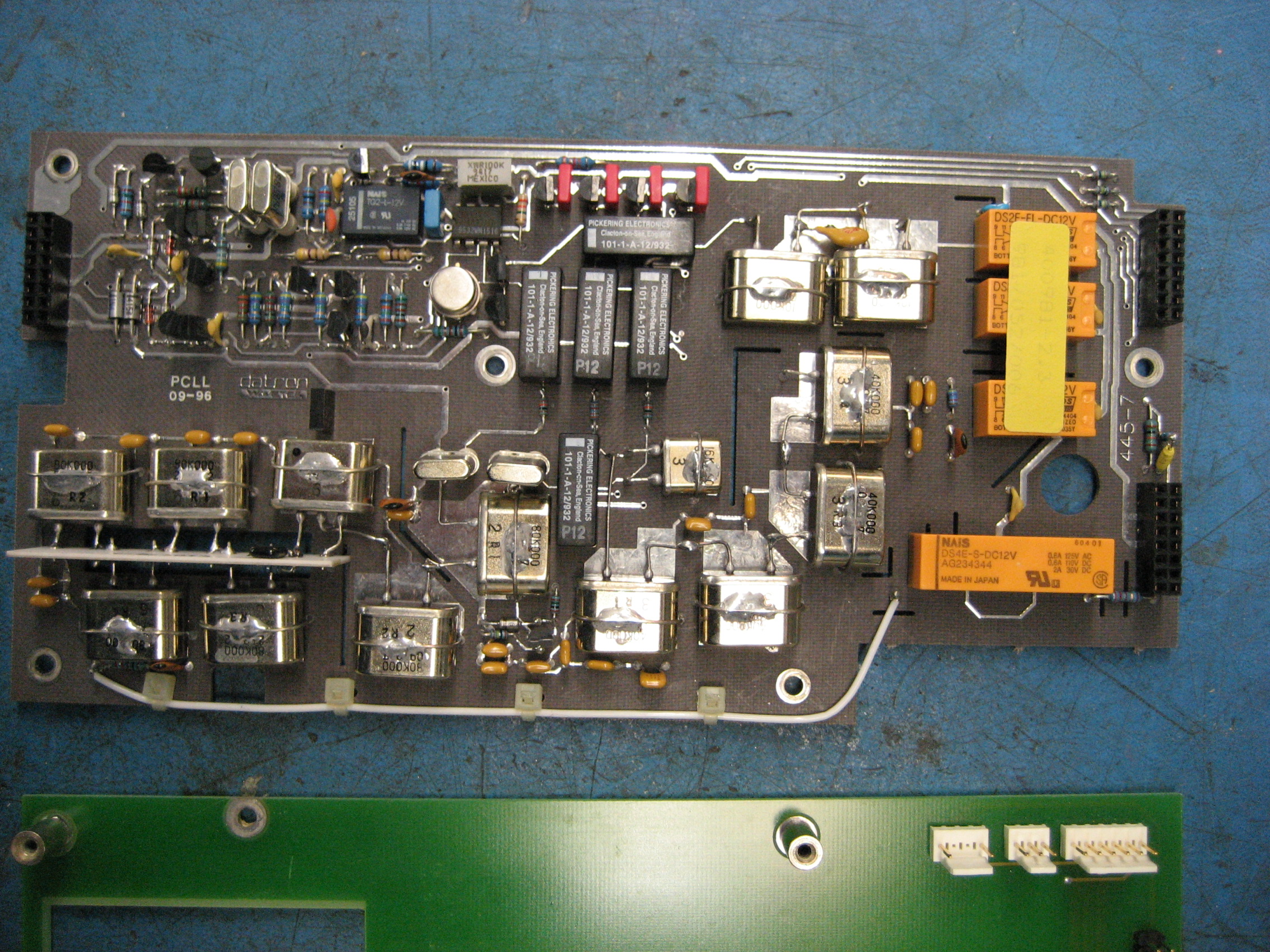
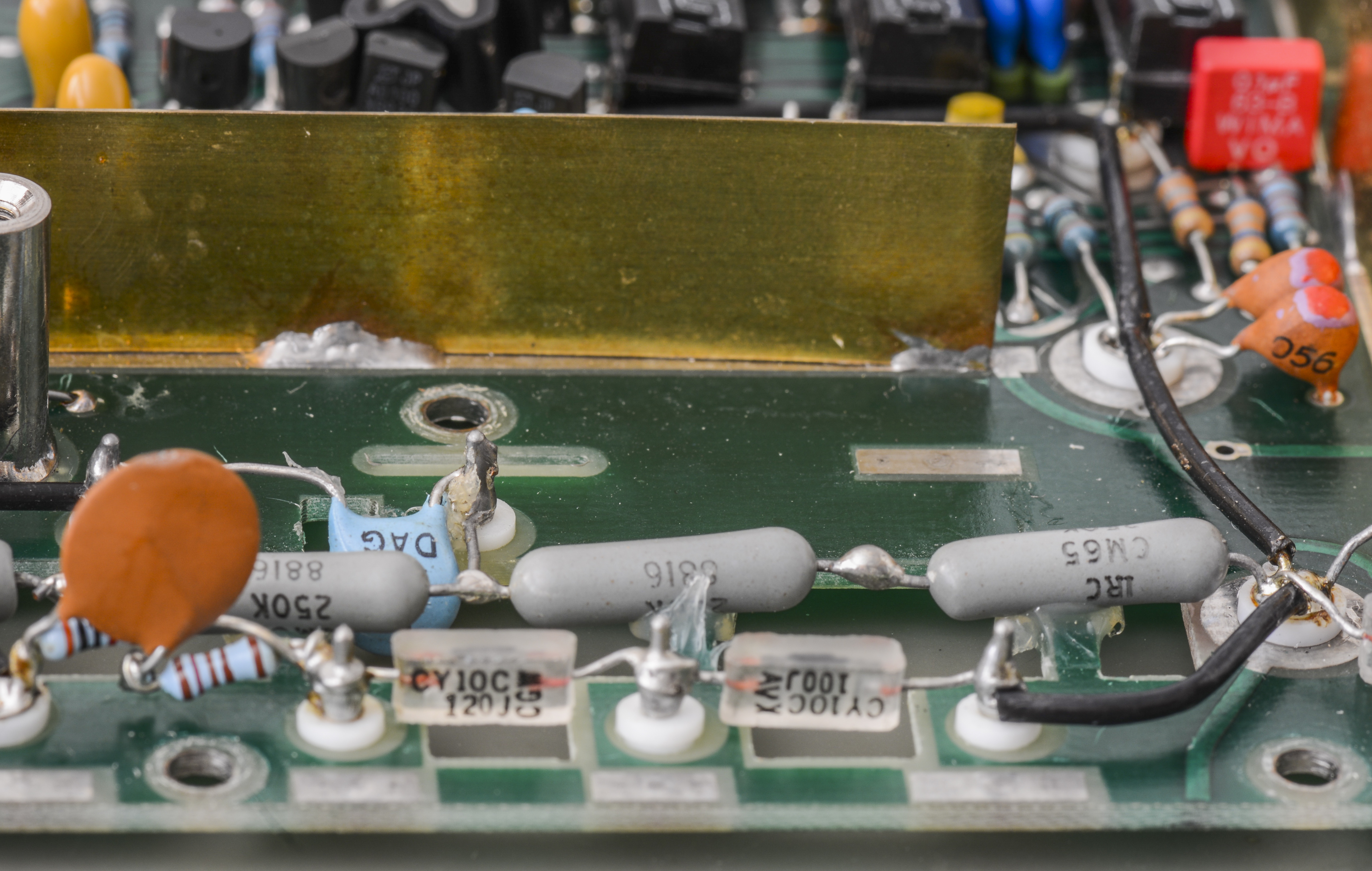
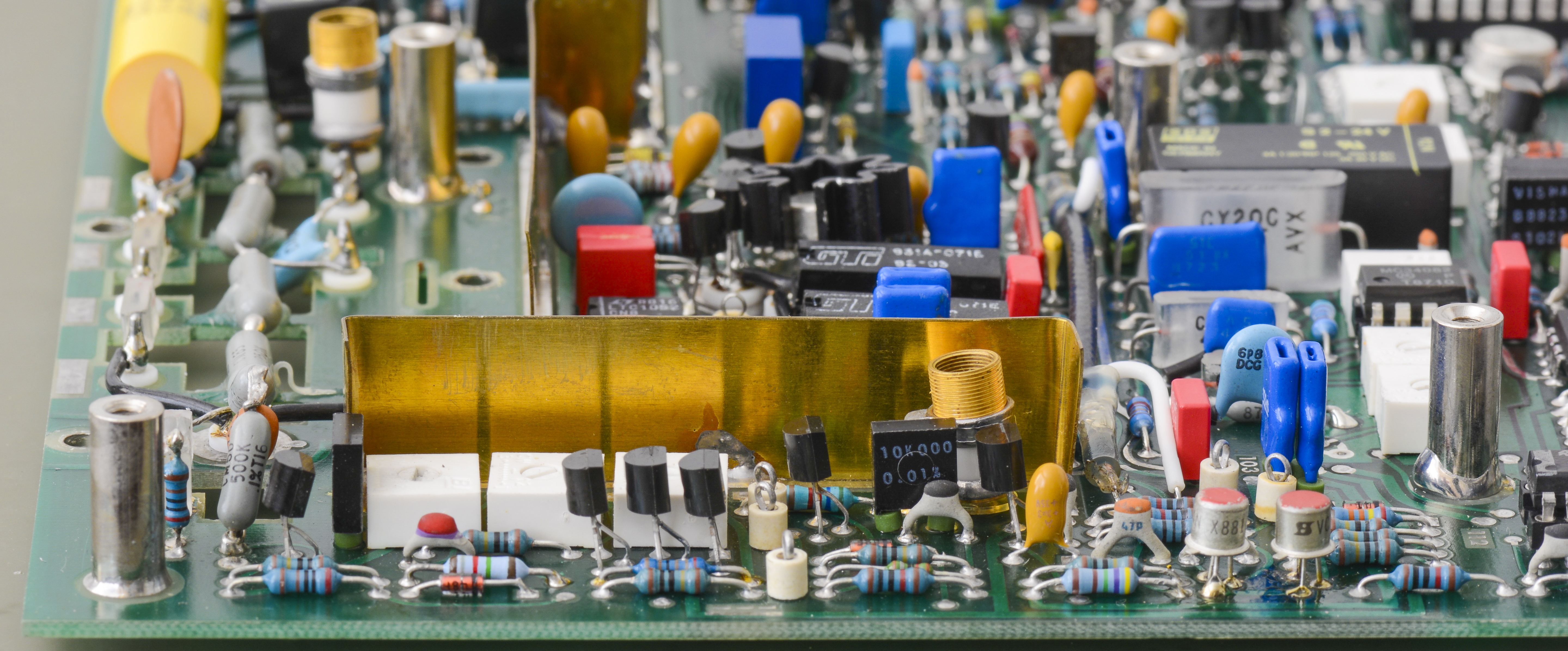
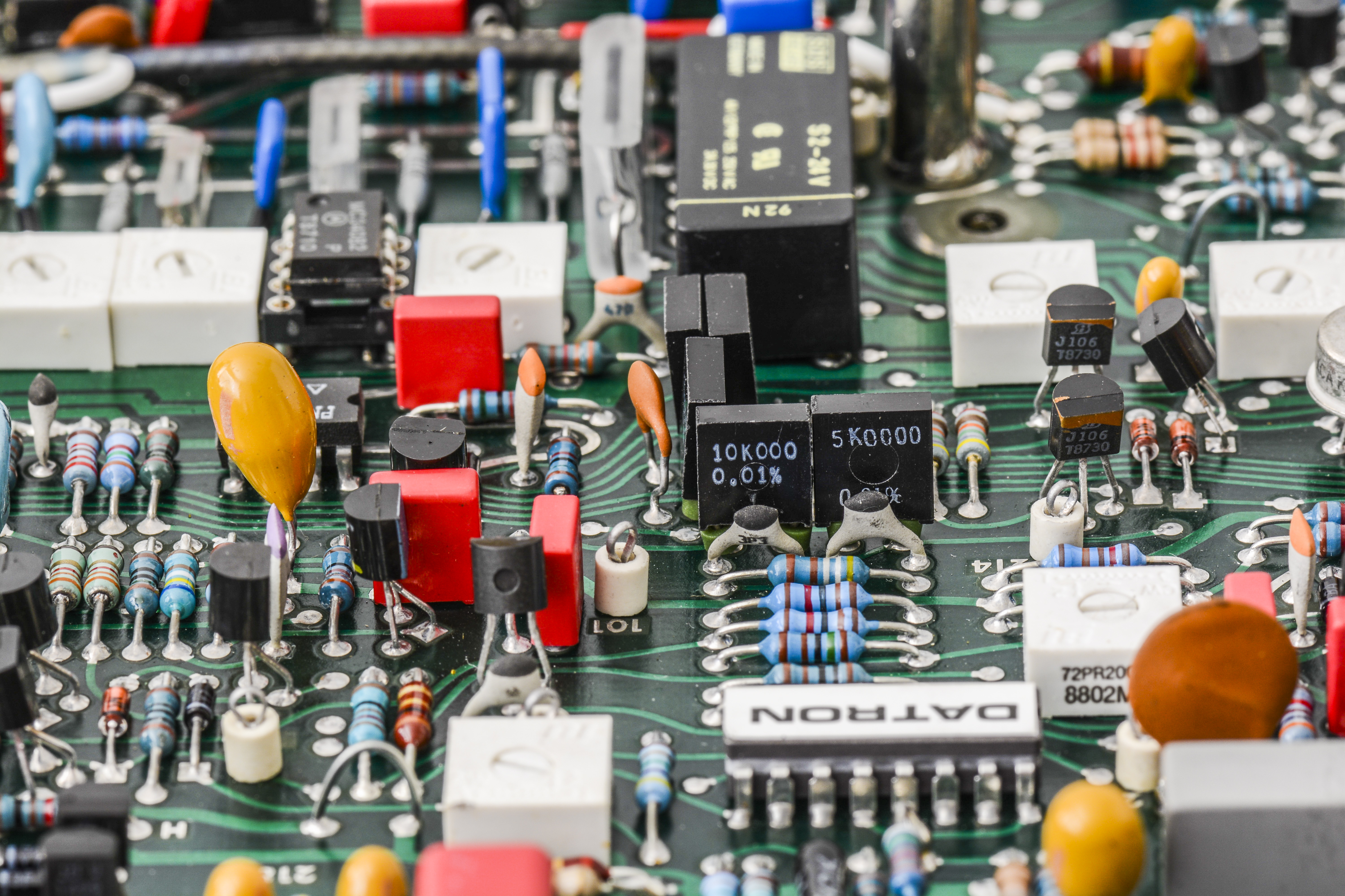
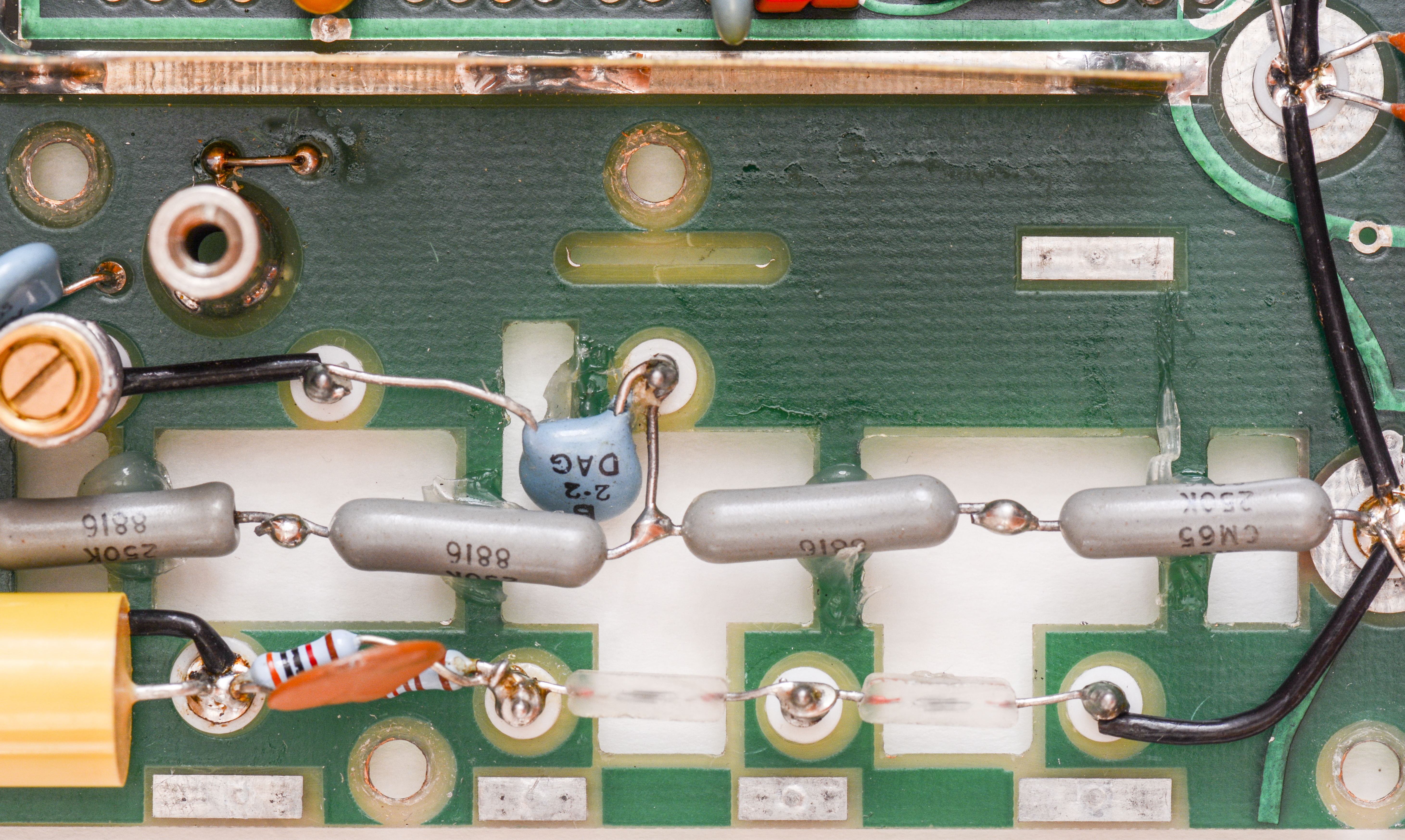
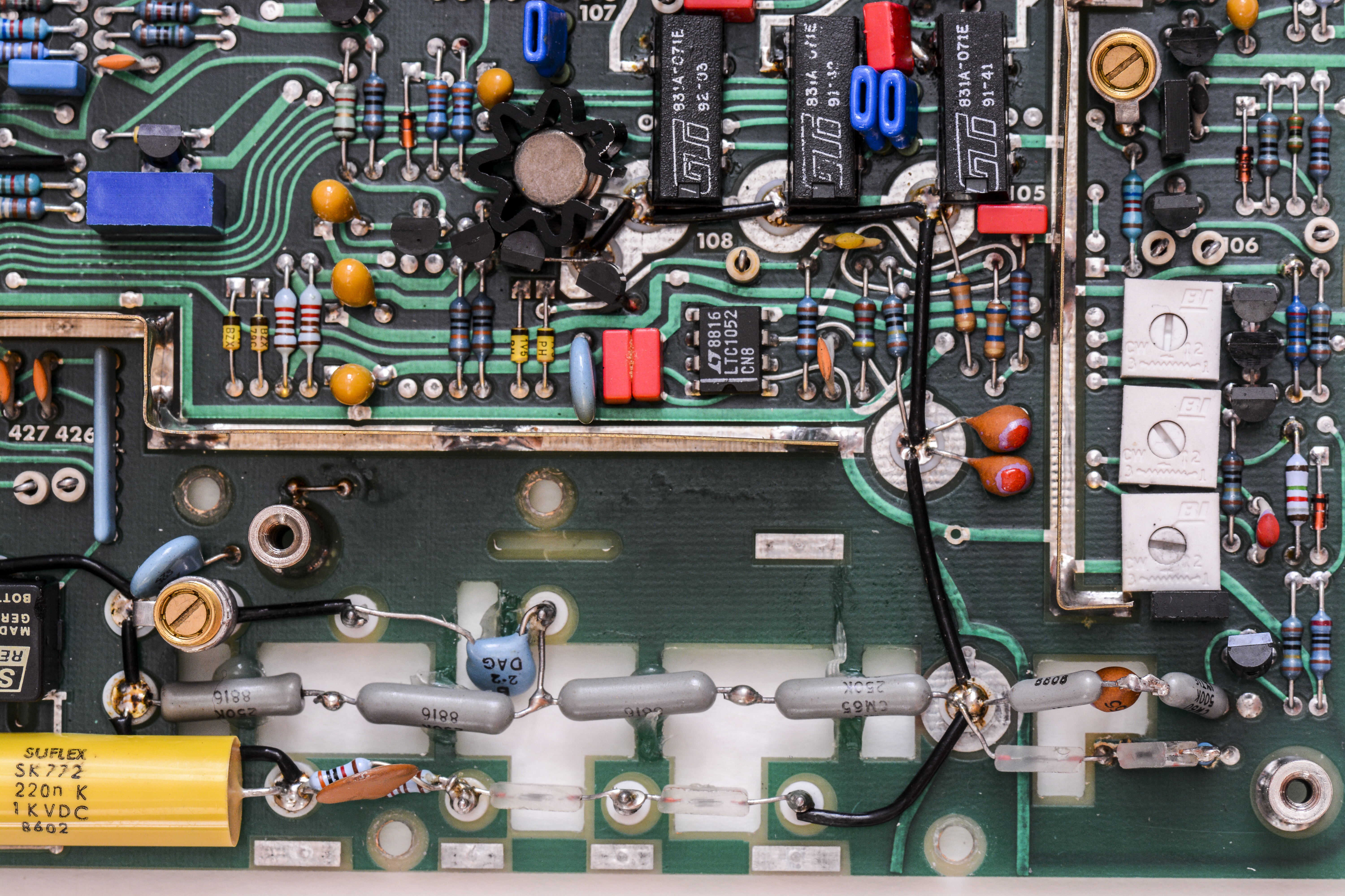
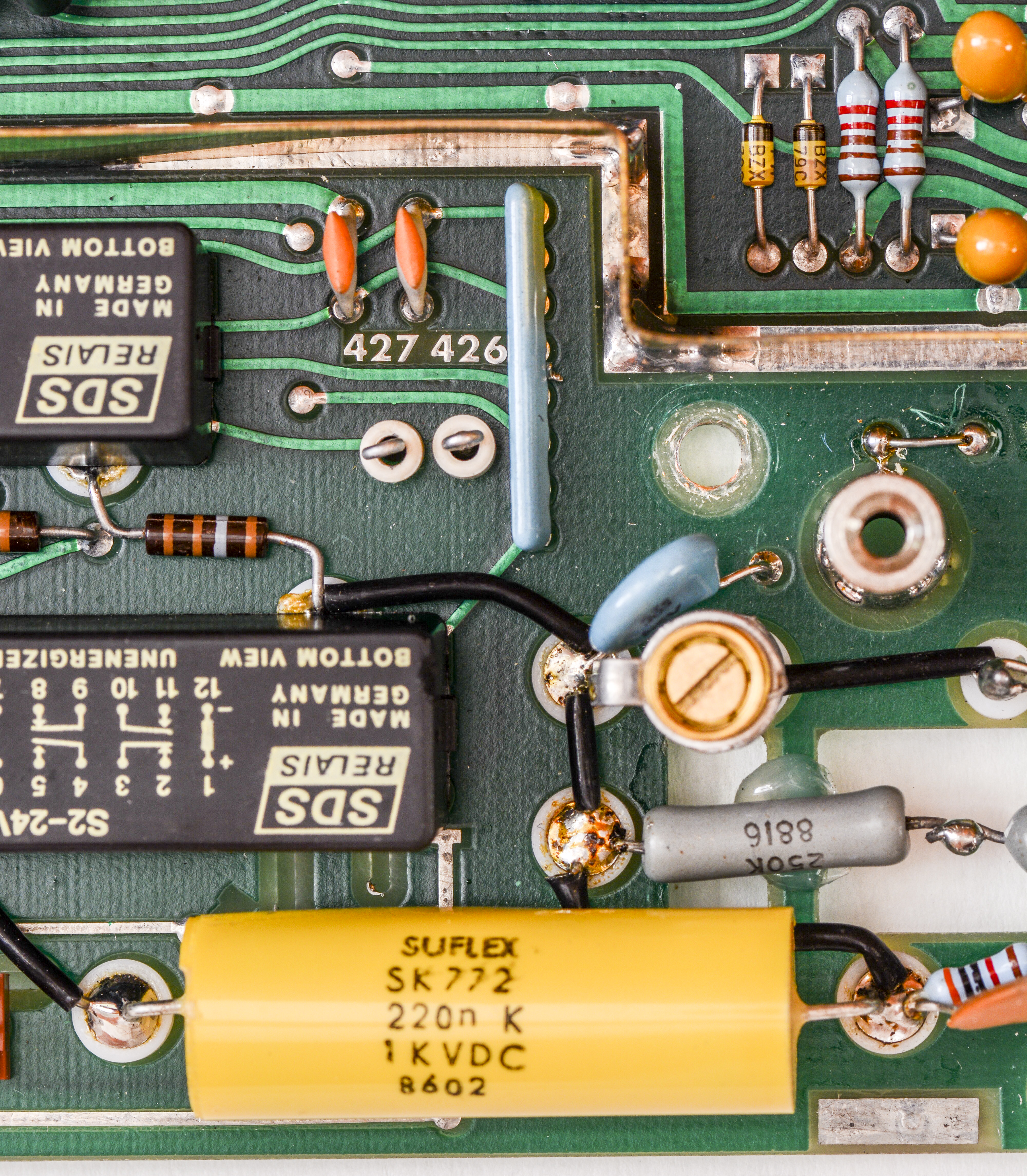
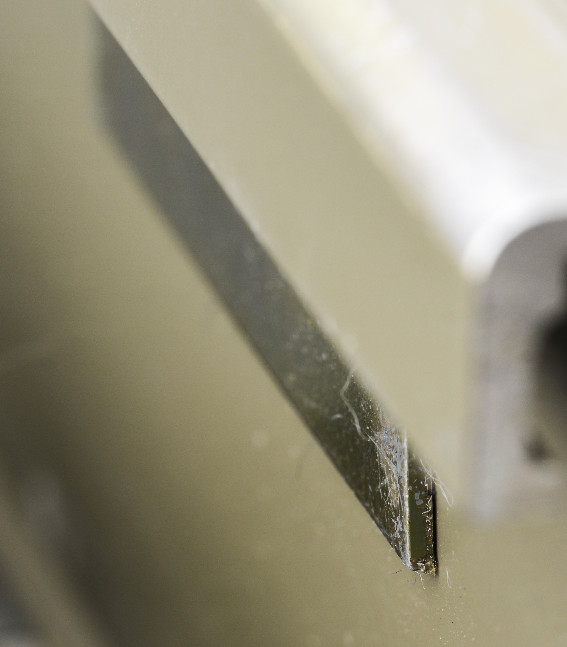
High-impedance signal routed thru array of 250KΩ high-voltage resistors with large cutouts in PCB to avoid leakage and capacitive coupling. It does not look good, but Datron engineers knew what they are doing.
Option 20 – 2-Wire & 4-Wire Resistance Converter
The Ohms assy was installed in the previous 1281 and a fast self-test was performed without errors. The board was inspected, cleaned of dust/debris, and photographed before it was reinstalled. No repair required here.

Option 30 – Current Converter
The Current assy was installed in the previous 1281 and a fast self-test was performed without errors. The board was inspected, cleaned of dust/debris, and photographed before it was reinstalled. No repair required here.
Front panel
No issues with front panel or display. It’s dark-gray color still with old Datron Instruments logo.
Other repairs
The lithium battery was not replaced. It is the same make as the first 1281 but an adapter board had been designed with FRAM so it was going to be installed in this meter first after it has been tested.
Paint on handles did not last well, having visible peeling now. There used to be magnets to keep handles locked in place.

The power input filter was replaced. Heatshrink was added to the P and N wires. Mains filter have soldered earth, just like in case with HP 3245A
The power supplies were remeasured. All supplies are close to as-found except the -35V supply. It was now measuring -35.3VDC with 0.11Vp-p noise. Just like the first 1281 nothing else had changed so it will be recommended that all supplies be checked even if the manual states they are not part of the affected assembly.
Quick check after assembly, with short on input terminals:
Input DCV +10V test:

Firmware
Firmware is stored in JEDEC-standard compatible ROM chips, such as:
- Hitachi Semiconductor HN27512G-25 DIP28
- ATMEL AT27C512 DIP28
| Firmware version | ROM1 U103, Part 1A | ROM2 U103, Part 1B | ROM3 U104, Part 2A | ROM4 U104, Part 2B |
|---|---|---|---|---|
| Model 1281, Version 3.02, Date 15-11-1988 | 1281 290159 CHK:0064A3A2 | 1281 290160 CHK:00B023DA | 1281 290164 CHK:0054F663 | 1281 290165 CHK:00AEE01B |
| Model 1281, Version 3.11, Date 16-6-1993 | 1281 290159 CHK:005CD06D | 1281 290160 CHK:00AD51DB | 1281 290164 CHK:004A7B3A | 1281 290165 CHK:00ACC784 |
| Model 1281, Version 3.12, Date 5-11-1996 | 1281 290159 | 1281 290160 | 1281 290164 | 1281 290165 |
Re-calibration after update 3.02 to 3.12 is not required.
Version 3.12 is also have faster self-test procedure with different amount of steps to run. Both meters show zero errors after tests.
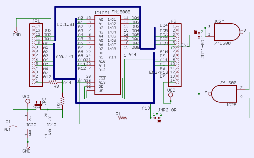
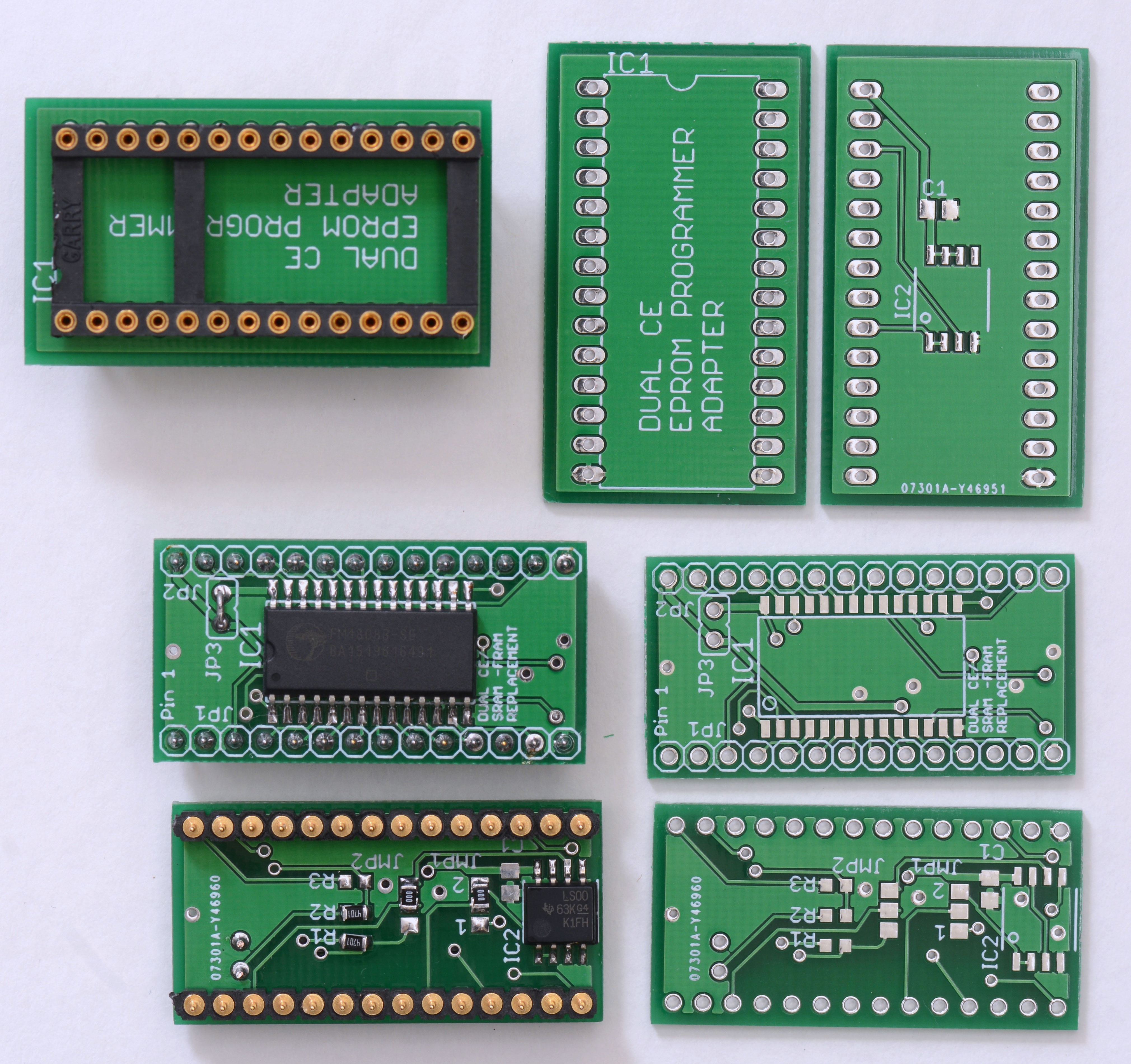
Custom FRAM adapters and EEPROM programmer adapter
To avoid issues with battery, simple FRAM adapter board was designed and manufactured. Tested them using different bit patterns, without any problems. Also EPROM programmer adapter board was designed to allow read/write of the new modules for backing up calibration data.
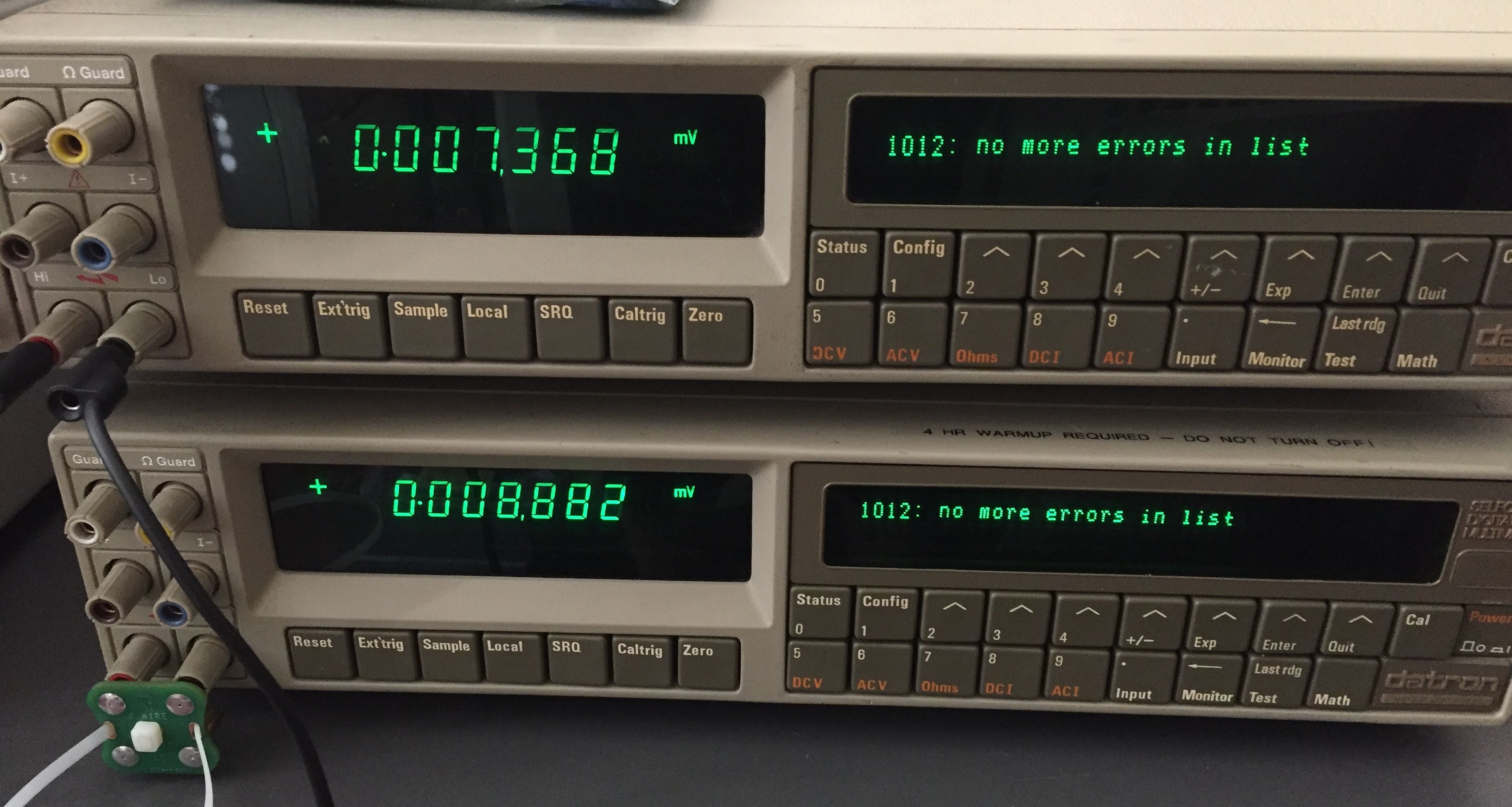
To test correct detection and operation Datron/Wavetek 1281 with FRAM special test binary was created, in which constants were reset and only the serial number + line freq were written, to let meter initialize EEPROM. The FRAM board was read and then programmed.
The meter came up with no checksum errors. The serial number was still correct as was the line frequency, as expected.
Schematics clickable for PDF.
FRAM adapter:
GERBERs ready for ordering at ITEAD Studio are also available:
Datron/HP NVRAM FRAM adapter board
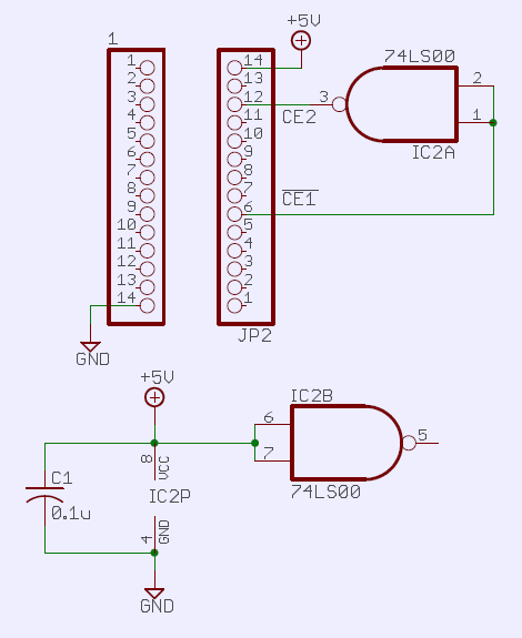
EEPROM programmer adapter:
GERBER:
EEPROM Programmer adapter for dual CE ROM chip
PCB prototype boards used for test:
Other possible issues
Block-diagram of serial communications data path from service manual can be handy to troubleshoot errors like 9005,9 pon tru/compl 001736. This 9005 series error usually means bad communication with one of option boards.

Jumpers LK704, LK703, LK702 can be used to bypass interface from optional boards to isolate and narrow down faulty module.
Happy meters now ready for calibration:
Tweaks and tricks
TBD..
Calibration
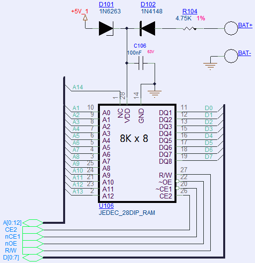
Calibration data is stored in U106 Toshiba TL5564PL-15 SRAM with Lithium battery backed up power supply. This is dual chip select (CE1 and CE2) 64Kb (8192 × 8 bits) 150ns CMOS SRAM, rated for +5V power in DIP28 package. Second chip select CE2 can be provided by inverting CE1 with external logic chip, such as 74HC00.
Performance verification
TBD
DCV Noise evaluation at shorted inputs
TBD
Restoration summary
Age difference between these Datron 1281 DMMs and more modern designs such as HP 3458A or Keithley 2002 is definately visible. Many bodge wires, reworks, hanging components from bottom PCB side, cut traces show amazing lot of debug and service on these instruments even after they went on market. Looks like these Datron/Wavetek 1271/1281’s are the most voodoo-intensive DMMs on the market with many custom today-obsolete components on every board.
It is even more amazing to see just few problems with both DMMs, most of which were resolved after simple capacitor replacement and reassembly. Hopefully they will continue to work few more decades.
This article would be impossible without Todd’s work, both units owner. All credits with discussion and raw content, photographs and testing go to him. Decision to make this article public was done to aid other owners of these precision multimeters from Datron. Also big credits to PeLuLe for complete service manuals, firmware v3.12 and his findings.
If you do have any questions, jump in comments! All the feedback is valued and can be added into article.
Projects like this are born from passion and a desire to share how things work. Education is the foundation of a healthy society - especially important in today's volatile world. xDevs began as a personal project notepad in Kherson, Ukraine back in 2008 and has grown with support of passionate readers just like you. There are no (and never will be) any ads, sponsors or shareholders behind xDevs.com, just a commitment to inspire and help learning. If you are in a position to help others like us, please consider supporting xDevs.com’s home-country Ukraine in its defense of freedom to speak, freedom to live in peace and freedom to choose their way. You can use official site to support Ukraine – United24 or Help99. Every cent counts.
Modified: Feb. 23, 2026, 5:32 a.m.