
Warnings & Disclaimers
Overclocking/overvoltaging your EVGA GeForce GTX 980 Ti KINGPIN graphics card on air, water, and LN2 temperatures can be fun and most of all pretty safe for the hardware, as long as it’s done correctly. This includes not only card PCB preparation for extreme conditions, but having the right software tools + capable supporting hardware(PSU) and a stable platform to test on. Taking the time and effort to prepare the VGA properly for more extreme forms of cooling and knowing some of the basics of overclocking, can go a long way to give a better understanding of exactly what is going on when you overclock your VGA at any temperature. Consider everything given below as “self-educational” and provided to assist in getting the most out of your shiny new KP card. Not only EVGA, but I think most vendors won’t warranty any hardware if it shows signs of being used and abused. Proceed with caution and at your own risk. Having patience and doing things in small steps can work wonders in providing the best user experience while keeping your hardware safe and benching over and over again.
Maxwell overclocking guidelines
Overclocking VGA’s today is made easy through a design like EVGA 980 Ti KINGPIN or other similar custom card. The voltage regulation components on the card and overall design/layout are much more capable than reference designs. There are also many different software tools available for adjusting voltages, fan limits, and clock speeds. Anyone can do it with a little basic knowledge of some key terms and practice. First, let’s talk about some of the major components of NVIDIA VGA overclocking software controls. Then some basic terminology/behavior of what’s going on with the GPU when you use those tools to overclock and overvolt the graphics card.
Power target and OC settings
This is main item limiting performance usually, as every NVIDIA card since the Kepler era has a power limit and circuitry on the PCB to measure input power. This control does not give you any amps or Watts value, but instead provides a percentage over design specification (which varies depending on card SKU/vendor!).
980 Ti KP has three different BIOS modes, which all have different maximum power targets keeping nominal power spec the same. If you want maximum OC headroom on air/water, you can just max this setting out and it will be enough.
Next up are the usual controls we use in EVGA Precision X for adjusting everything on the card in windows:
- GPU Clock offset – This is GPU core clock adjustment setting.
- MEM Clock offset – This is memory clock adjustment setting.
- Voltage – for increasing the power to the core (1.212V limit in Precision X) or use classified voltage controller/EVBot for higher.
- Fan speed – Always max these when pushing the card on air
- KBoost – This is critical for getting the best scores when pushing the limits. It forces the driver to P0 state on a SW level and can prevent the card from sticking low at 2D clocks in between game tests while running benches. This can hurt the overall FPS in a benchmark a lot, and usually results in slightly lower score. On LN2, its most necessary.
Always use K-boost when doing any kind of benching!
Also if you benching with VGA cable (some cards might have no display issue on digital interfaces, such as DVI, HDMI, DP when running very low temperatures), you will need use secret menu in EVGA Precision X to make KBoost working. To access secret menu open Precision X, press Ctrl+Shift+Middle wheel on mouse and extra window with experimental features will pop up.
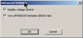
- Disable voltage control – this feature prevent Precision X to control any voltage settings.
- Turn off KBOOST limitation – this feature allow you to still enable KBoost even if using VGA output (normally it’s disabled, due rare compatibility issues)
Enabling real voltage monitor
There is one more trick, regarding voltage readout in Precision X and K|NGP|N Edition cards (both 980 and 980Ti flavours). As you all already know, software is unable to show real voltage supplied to GPU, it shows what GPU VID setting currently is, not actual voltage. Most of users are not aware of this detail, and expect to see real voltage. That’s why we often get confused people in forums, who see LN2 records with 2000MHz clocks and asking how is that possible with only 1.212V?
Well, KPE cards have a solution for this, as Precision X can actually read real voltage. KPE PCB have special circuitry to measure real voltage delivered to GPU chip and Precision X can get that reading. This is not default enabled feature, so to enable real GPU voltage monitoring, follow few simple steps before you start your session:
- Download latest Precision X, at moment of writing it was 5.3.6
- Set both OVERVOLTAGE and OVERBOOST mode in Voltage section top right. No need change voltages.
- Now VOLTAGE in center section will read actual voltage delivered by hardware.
- You can disable voltage control via secret menu after, reading still will work.
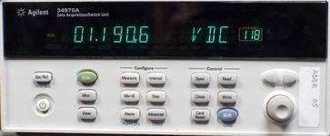
Screenshot below shows example usage with 1.400V set. GPU Voltage is reported correctly in hardware monitor graph, log and OSD as well, which can be handy to monitor voltage droop/change during benchmark sessions. And after you found sweet spot for voltage, disable OSD and run for records (OSD have little performance hit when running, so you want it OFF when benching for records).
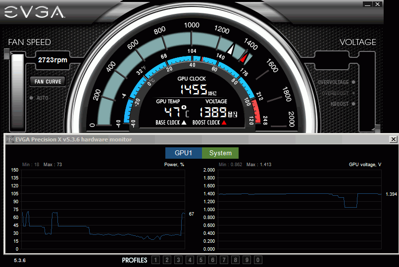
There is no limit on reading, so even 1.8V will be reported correctly. Again, this works only for EVGA GeForce GTX 980 KPE and EVGA GeForce GTX 980Ti KPE cards.
Overclocking methodology for Big Maxwell (GM200)
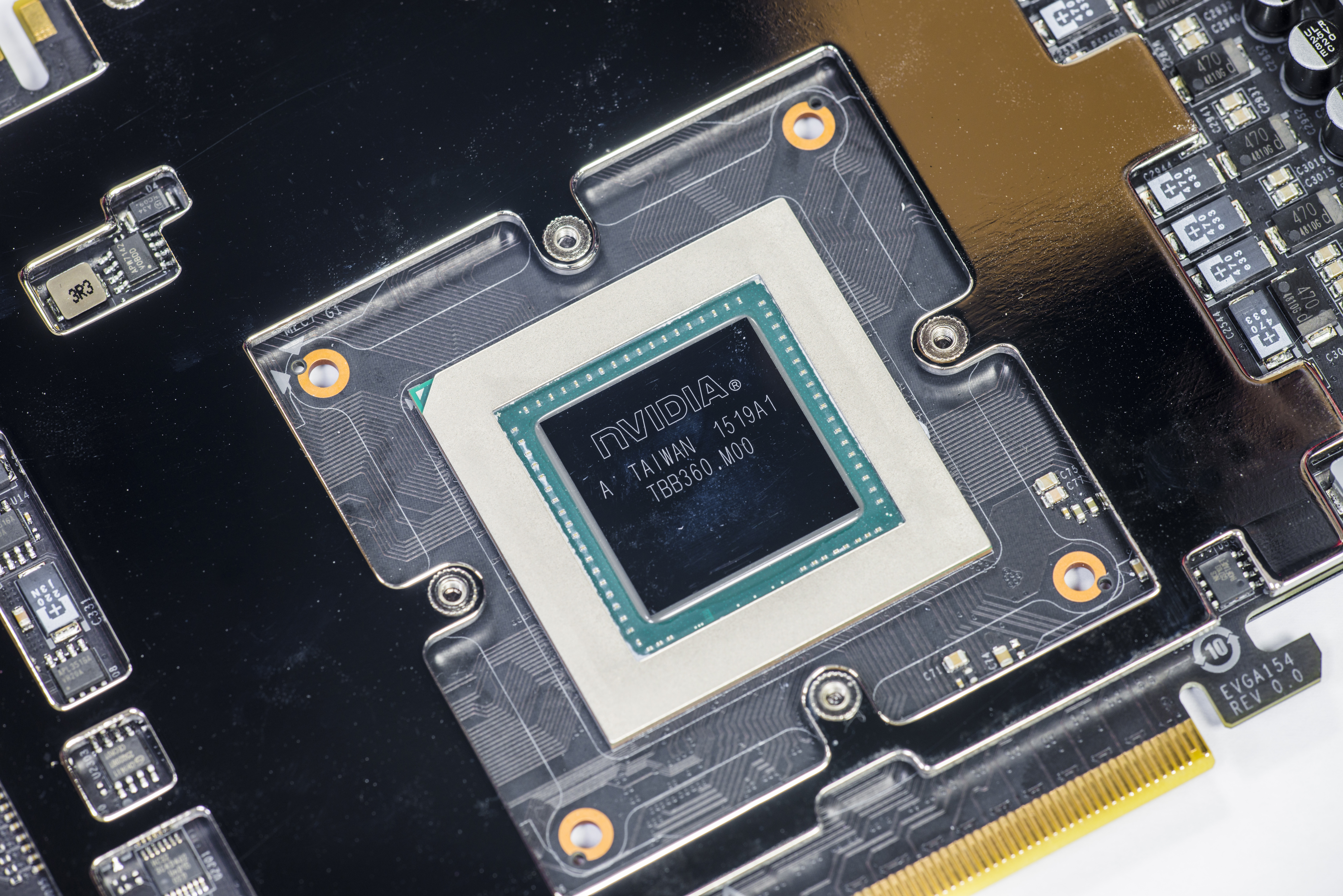
EVGA 980 Ti KINGPIN as well as all other 980 Ti, 980 and Titan-X cards use a GPU featuring the NVIDIA Maxwell architecture. Given what we already know about it highlighted here before, we know that Maxwell GPUs don’t really benefit from much overvoltage on air and water cooling temps. If you give it some thought, it’s due to fact that power-efficient Maxwell is already close to pushing frequency boundaries when running at ambient temperatures. So then it seems Maxwell doesn’t seem to like much applied voltage at ambient temperatures. Well, how does applied GPU voltage normally work on other GPUs normally? There are two ways:
Voltage relation to chip operation
As your card clocks go up, it’s harder for the electrical gates in the GPU to switch due to more noise generated and the increased demand for current from the power supply. There is also an overall increase of temperatures inside the chip structures internally on the GPU. At some point, the applied voltage is just not enough to keep the internal gates switching reliably and this creates errors/artifacts. The result is the GPU will crash. Raising voltage will provide that extra power the GPU needs, but it will also skyrocket GPUs temperatures internally. If you are still below “maximum” temperatures for a specific frequency, the GPU will remain stable and continue working well. There are safe typical temperature ranges for different voltages. These are like “sweet spots” with regards to voltage/frequency/temperature.
Voltage in relation to power consumption and temperature
Increasing voltages and improving the cooling to reach max clocks, this is basic overclocking. Keep in mind increasing voltages always brings an increase in power consumption and internal GPU temperatures. This is not a linear relationship, but more like an exponential one. When you increase voltage 10%, your power usage and temperatures will not increase just 10%, but more like 25-30%. This is very different to frequency gains, which are more linear (10% faster clock gives close to same 10% power increase). Even at extreme cooling temperatures, this rule still applies because -100 °C at die contact surface is still not enough to cool down heavily overvolted chip logic structures buried deep in the silicon. It will still overheat at one point no matter how cold temperature is, if voltage and power consumption is too high. This behavior is important to know, as it is the basis for all overclocking, extreme or not.
Maxwell is designed and optimized very well to run at high frequencies. This means that while keeping voltages and temperatures at normal default levels, you can get amazing clocks. Most of the GM200 GPUs on Titan X and 980 Ti cards can run 1450+ MHz, which is already considered very high clocks given the chip complexity and size. There is some headroom left for scaling at ambient temps, but not much.
Overclocking at frequencies beyond 1450 MHz really depends on quality of silicon and how high it can scale. Another important thing is whether the GPU is taking more or less power at default spec.
BIOS & Tools
BIOSes in this section compatible only with EVGA GeForce GTX 980 Ti KINGPIN, and will not work on regular 980 Ti CLASSIFIED or any other card.
Card is shipped with three different BIOSes:
Normal BIOS – This BIOS is stock baseline, +130% Power target limit
OC BIOS – This BIOS similar to Normal but with 7096MHz memory, +150% Power target limit
LN2 BIOS – This BIOS have similar to OC, but with 170% Power target limit
Custom BIOS
This OC BIOS have next features
- Unlocked maxed-out power limit
- 100% unlocked fan speed
- 3591 MHz memory clock as base
- Disable protection for subzero
If you plan to run LN2 temps (below -60°C) should use LN2 switch position (Red LED BIOS), to disable hardware thermal protection mechanism.
Overclocking
Clockspeeds, voltages, and temperatures. All these variables work together and must be dialed in correctly for the best results. The following are the normal overclocking ranges you can expect for the majority of cards, however every card is not exactly the same. More fine tuning will always get the best results on your card. Some cards will use more/less voltage and for sure some cards will go colder than others on top end. As suggested earlier, overclocking in small steps helps to learn exactly what your particular GPU needs for every MHz upward.
Air/water cooling clock/voltage/temperature range
The cards clock range on AIR cooling using the default 980 Ti KINGPIN cooler will vary and these are only guidelines of what the average card will do. ASIC level and ambient temps can have an impact on how high the card clocks on air. Every card will be different and ASIC is NOT a guarantee of anything, especially at air cooling. It is just a indicator as mentioned before. Generally, most cards with an ASIC of 70% or more should hit 1500 and up on air using DEFAULT CORE VOLTAGE. Cards with ASIC ranges up to 74% can hit the low 1500-1530’s, and cards with ASIC of 76% and higher have the greatest chance usually to hit 1550 MHz+.
Because of Maxwell voltage scaling as discussed before, in most cases adding only a small amount of voltage can help. 1.21-1.22v under load at DMM is about the most you can go on air before you will get artifacts on screen. I find 1.19-1.2 V to be nice sweet spot on most GPUs. Adding voltage in most cases just results in more artifacts and instability. Find the limit of your GPU by using default voltage first, then see if adding voltage helps at all.
LN2 cooling clock/voltage/temperature range
The card scales Maxwell GPUs to the limit and is capable to hit 2 GHz and beyond core frequency with the right amounts of voltage and temperature. Fully maxing out these GPUs on LN2 usually requires around -125 to -135c on the GPU container, and roughly 1.72v-176v under load at DMM with the correct Vdroop to balance the GPU switching from idle/load. The higher the current usage, the more the Vdroop can help with smoothing out the cards power usage from idle to load. Core and memory voltage droop settings will be covered more specifically later on in this guide. The thermal grease you use and the mounting accuracy/pressure also has a big impact on max clocks. It’s critical that the contact surface areas of the pot and the GPU are aligned and mounted correctly, or you can lose 150 MHz+ on top end. I’ve gotten 2000 MHz on cards that previously could only do 1850 MHz due to only bad mounting on previous runs. Bad mounting causes a poor temperature delta between the GPU pot temp and the die temp on the GPU itself. With 980 Ti KINGPIN, there is an internal monitor so you can actually check the delta of the card to see the contact accuracy and grease viability (frozen or not). These two aspects are CRUCIAL to top end extreme overclocking. Both are covered later in the guide.
This guide doesn’t cover insulation and condensation preparation of the card itself, as there are different ways to do this and everyone has a preferred method. I figured maybe it’s best to let some guys post their own methods here that work well. This lets you decide how you want to insulate your card your own individual way. Check around KPC or the usual internet forums for insulation guides for your graphics cards. Once the 980 Ti KP is prepped, container is mounted, and card installed into the system, you’re ready. Do a quick post/boot before putting ANY LN2 into the container just to be sure everything is still 100% functional on the card after you mounted it. Check that the drivers are still working/installed, check for artifacts on the screen, even run a 3Dmark at default settings. If the container warms to 30-40 °C under load, just splash it with some LN2, don’t let it overheat is all you need to worry about. If it can’t pass this, it will never overclock. That means it’s time to break down the rig, see what the problem is, and start over.
If everything is OK, then let’s move on. Word to the wise, you can NEVER just pull the card down to min temp (-125 °C), set max voltage(1.65v+) and think it will run alright. This is NEVER recommended and something I’ve always preached against since the beginning. Impatience will lead to bad extreme overclocking sessions. The proper way to overclock a VGA to the max clocks it can run is to go in steps, working your way up in voltage and down in temperature, like the following. Adjustable on the fly Vdroop changes can help when tuning in max clocks. Voltages shown are measurements taken at the probe it reading point for core voltage:
| 1st boot/check | Ambient | Default voltage |
| -50 to -60 °C | 1650 MHz | 1.55 V,droop disable |
| -80 to -90 °C | 1750 MHz | 1.65 V,droop disable |
| -90 to -115 °C | 1850 MHz – 1900 MHz | 1.7 V, mild droop |
| -115 °C and beyond | 2000 MHz+ | 1.75+ V, med-most droop |
Again these are typical LN2 scaling numbers of what most cards can achieve. While all KP980Ti PCB ‘s are capable to push Maxwell 980 Ti GPU to well beyond the limits, all GPUs are different. Factors such as ASIC, leakage, and container mounting can have a big impact on the end result.
Memory overclocking
In modern benchmarks like 3Dmark Firestrike or Heaven, graphics memory overclocking is just as important as the GPU.
Much thought was given on 980 Ti KINGPIN with regards to memory during the card design to optimize memory performance to its fullest.
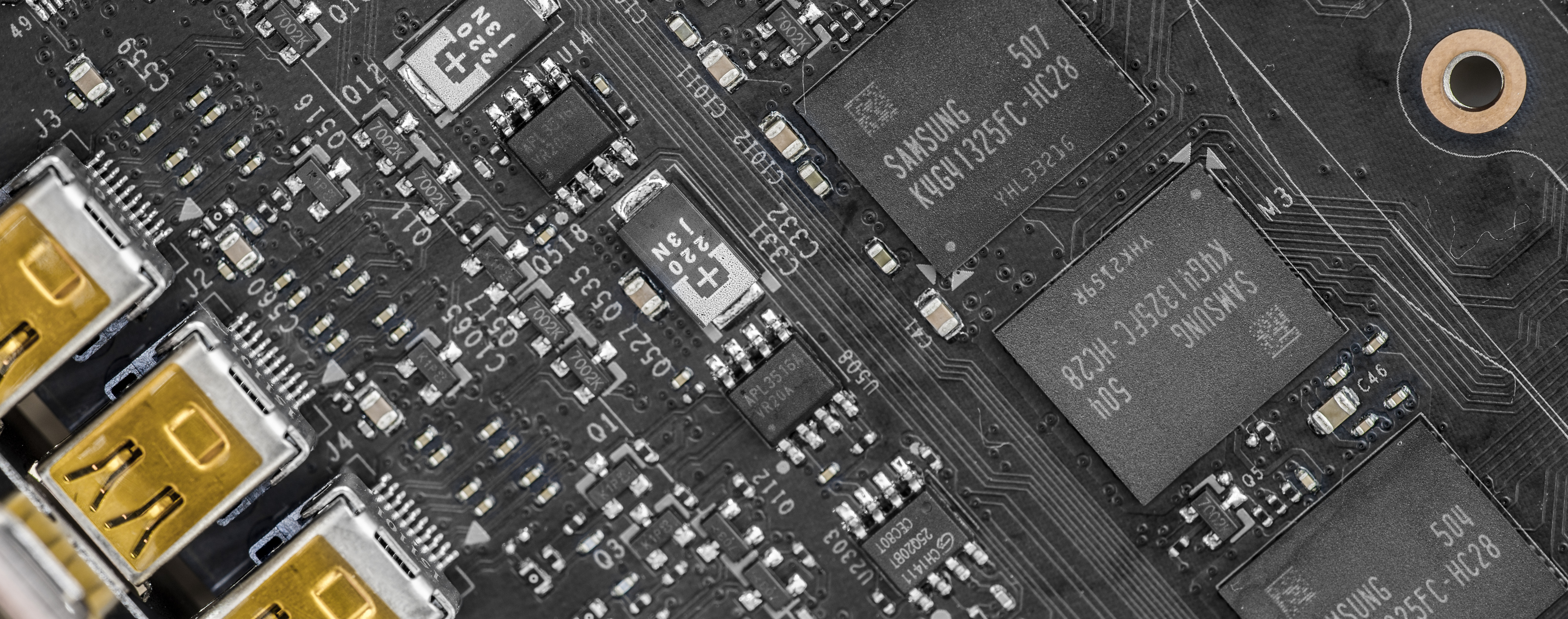
To start, all 980 Ti KPE cards are equipped with SAMSUNG 7Gbps memory chips. Currently, this is the only 980 Ti card available which features Samsung memory. Why the buzz about it?
Two main reasons:
1. Samsung is faster clock-per-clock against Hynix due to some tighter latencies and the ability to run higher voltage. This improves the performance a bit over that of the reference 980Ti.
2. Samsung memory can scale nicely with memory voltage. This means that if you provide more voltage to memory than stock 1.60V, you will very likely get higher overclocking on memory. Hynix memory fails at this as most IC’s are usually unable to cope with elevated voltages. 3D apps will crash on cards using Hynix memory even at stock 7Gbps clock if you raise the memory voltage. Usually over 1.7v is enough to make it unstable. Because of this, Samsung memory is THE BEST choice for a high end overclocking card and why 980 Ti KINGPIN is built only with Samsung IC’s. When you are overclocking on LN2, you want to match the highest core speed + highest memory speed. This is what gives the best score and Maxwell GPU cores actually need higher memory voltage to keep the memory controller portion of the GPU from bugging on cold and limiting max memory OC. Hynix memory can’t scale with voltage, so a lot of Ti’s and Titan-X GPUs end up NOT being able to hit their max core clock due to this. We saw this behavior over and over again in the lab on many Titan-X and reference 980ti as well as some ES experimental 980 Ti KINGPIN cards with Hynix memory.
When pushing your card hard on LN2, always raise the memory voltage about 1.80 V TO START, and the GPU will require more like around 1.85 V or higher depending on the GPU to keep the memory clocks high on LN2 and scoring correctly. This is critical for 980 Ti overclocking and getting the best results.
You may find that your card can do ++700 on air even using default voltage. This same GPU on LN2 will require more memory voltage to keep the same memory overclock stable when GPU is being pushed 1850+. That’s how it works.
Keep in mind that the cards memory is calibrated when it initializes and the boots windows. Sometimes when raising memory voltage for example to 1.8v at idle desktop, it can cause the GPU to lock and artifact. This is normal and happens because the memory has already been calibrated at lower voltage, long before you got into windows. A simple reboot after desired voltage is set, and everything will be working 100% fine on next boot into windows with raised memory voltage. Running very high voltages on your cards memory for extended periods of time may degrade the IC’s slightly, so be careful not to overvolt when not necessary. Spend some time finding out exactly what memory voltage your cards needs to run at different temperatures, so it’s not set too high for the clock and all should be good. I run 1.82-1.85 V on cards on LN2 temps always. For air cooling, usually I don’t go over 1.8 V and it seems to be able to handle it so far. The memory can scale very high on some card using higher than 1.90+ V, but please do so carefully. I have seen some cards IC’s degrade at voltage over 1.94 V/air and running extremely high frequencies (750+ offset on memory, = 2250+)
Power limit & requirements
This was already covered many times on web , so we will link it in this guide too. However KP980Ti does not need a power limit mod or any thermal limiting mods. It can overcome the power limit or any thermal limit with a simple BIOS flash. It is 100% designed to not need any additional modding at all to run @full speed.
Card overclocked with LN2 and running 1800+MHz can take some serious power, so ensure your PSU is adequate for the job. We highly recommend running system (CPU, peripherals, fans, motherboard) from one PSU, and VGA card from separate second PSU, with at least 1200W of power on +12V rail.
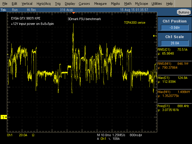
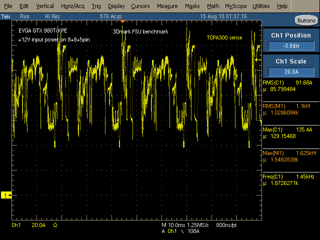
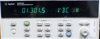
To show what card is capable of, here are measurement results of +12V current consumption at 8+8+6pin plugs during 3Dmark FireStrike Ultra runs:
Idle power during benchmark loading screen, ~30A taken, near 400W, 1800MHz 1.65V
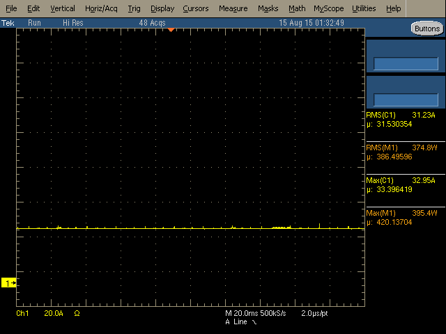
Running GT1 test, ~71A taken (850W), max peak is 125A (1500W), 1800MHz 1.65V
Running GT1 test with higher clocks&voltage, ~92A (1100W), max peak is 135A (1625W!), 1950MHz 1.74V
Running GT2 test with same settings as above, ~77A (927W), max peak is 133A (1603W).
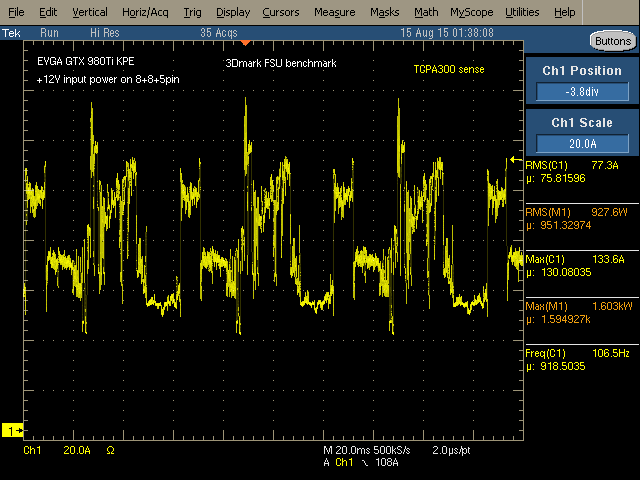
All results were captured with GPU cooled to -100°C, using Tektronix TDS5034B scope and TCPA303 current probe.
Alternative functions
If you are a first timer to the extreme world, you might not have lot of experience about what hardware mods to do on your card, or what traces you need to cut to disable overtemperature/overcurrent protections.
No worries, you can use KPE just as it is for the ALL your LN2 sessions. You only need voltage control tools, which could be either EVBOT, SW tool such as classified voltage controller, or even fancy Raspberry Pi. As already mentioned, 980 Ti KINGPIN is designed so there are no hardware modifications or soldering required to reach maximum clocks with your GPU and VMEM, just like all other Kingpin edition cards.
However, If you want a little more fun than just max clocks and performance, we have included a few extra tricks/mods to help you out and get even more from the card with some easy soldering.
Card PCB surface heater
One common enemy of extreme LN2 overclocking is condensation and water. Water gets everywhere when LN2 overclocking. It gets between tiny components, it can run into the PCIe slot. When it does this it can short power circuits and cause all kinds of problems and possible disasters. It’s not good to have card wet during operation, and condensation is an age old common problem when running GPU subzero.
The point of LN2 overclocking on a GPU is to freeze the GPU and nothing else. Everything else on the card, such as discrete components in display output area, is much better working at ambient temperatures. And for many years extreme overclockers were using heatguns to keep that area warm, as there are no parts which dissipate much power and without external heating front area of PCB get cold really quick. Warm PCB keep the GPU signaling correct and reduce icing on critical areas.
So is there a solution without external heatgun? It’s possible with 980 Ti KINGPIN cards to use dedicated design feature that keeps PCB layers always above negative temperatures. It also keeps the memory IC’s from bugging out due to cold. While Samsung is the least buggy of GDDR5, it still runs best when it is not frozen solid. This PCB heating feature is needed only for hard-core LN2 overclocking, so we fully de-activated it by default in stock condition.
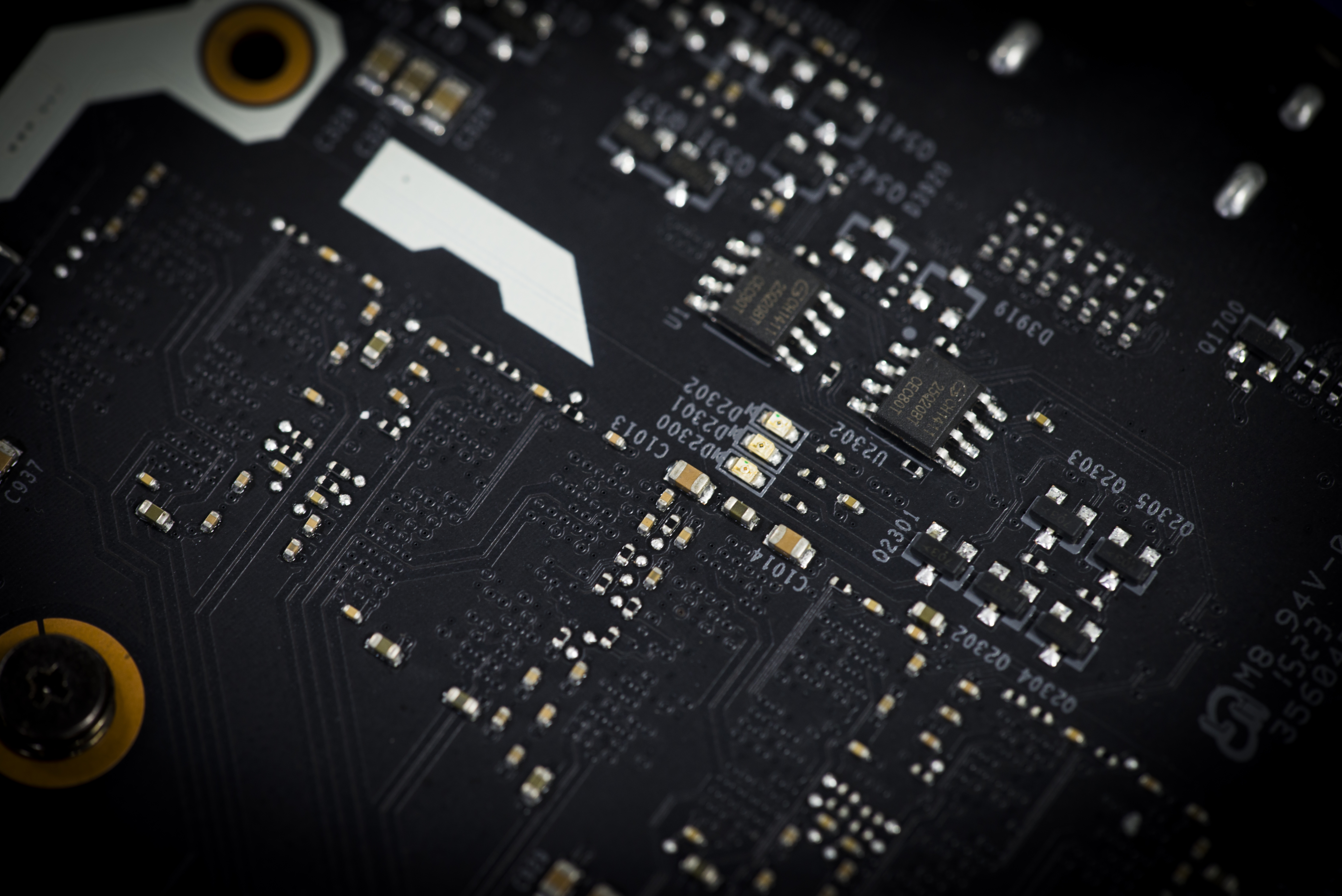
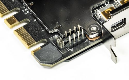
It’s a hardware-based solution, which means it will be automatically on when activated. To enable the KP PCB heating element, you will need to put 5 shorting points at top PCB surface as marked and shown on photo below:
That’s it. Now card will automatically pre-heat PCB when GPU reach a specific temperature. You don’t need to do anything else, it is a “smart” heater :). The heat load will be adjusted automatically depending on your GPU load, PCB temperature, ambient temperature, and PWM power loading. All you need to worry about is to have enough supply on PSU side.
PCB Heater may take up to 150W. A fully overclocked 2GHz card with -120 °C usually will draw around 1000W power from +12V, so if you use heater make sure your power supply powering card is at least 1200-1300W to have some safe margin.
That’s for single-card power ONLY. This doesn’t account for CPU, peripherals, any high-speed high-power fans, etc.
Integrated monitoring
This feature can be used by connecting any popular TTL UART to USB converter to serial port on card. Server crowd sure knows about serial consoles, as these used widely to remotely control rack mount hardware. This is a new thing on gaming VGA cards however. If you don’t have serial dongle, you can get all-ready-to-go solution here or little DIY module here . Both are pretty cheap, and likely to be less than 5$ at sites such as ebay. Pay close attention that you need UART-USB adapter, not RS232-USB (RS232 is same protocol, but much higher voltage).
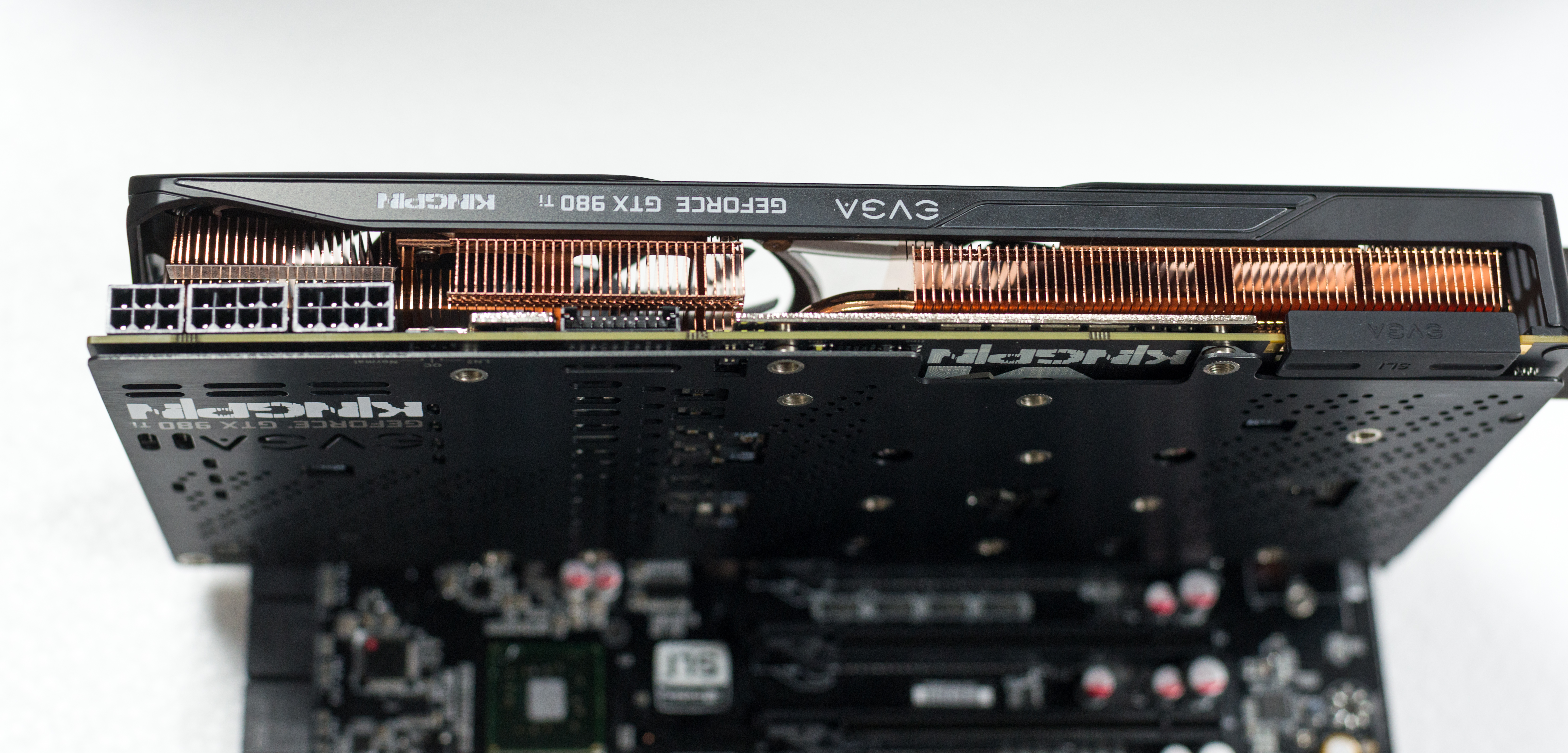
Interfacing is done via onboard header located near SLI edge ports.
You have access to this port with both stock fansink operation and watercooling/LN2.
Connect UART cable to VGA’s serial port like this photo below. It could be little tricky to get cable between fansink cover, so use twizzers to fix cable in position.
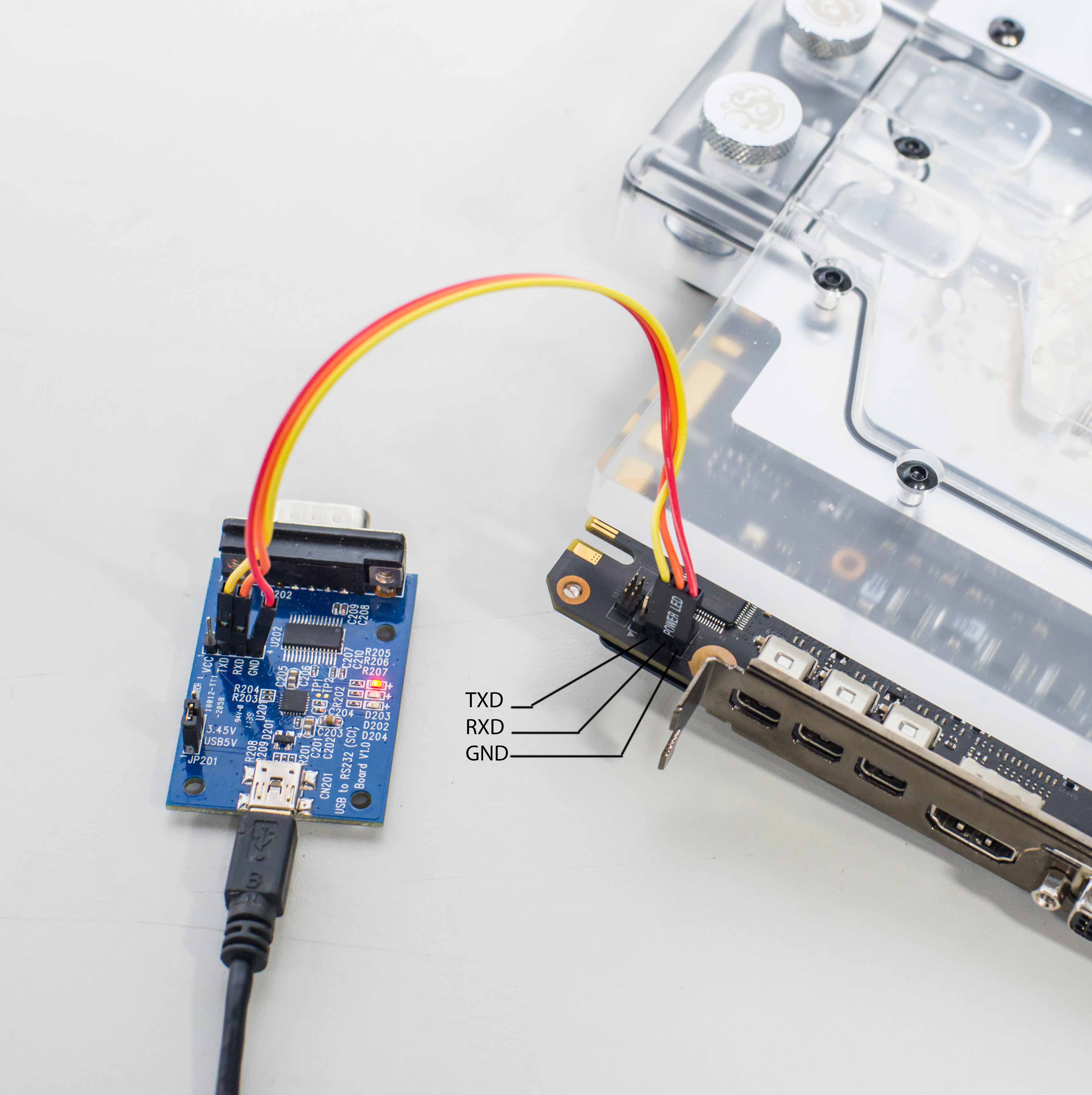

USB end of serial cable goes to your PC or smartphone via OTG, or any other device able to capture serial stream at 115200 8N1 speed.
We use the popular putty , and if everything is connected properly, you should see this :
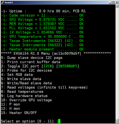
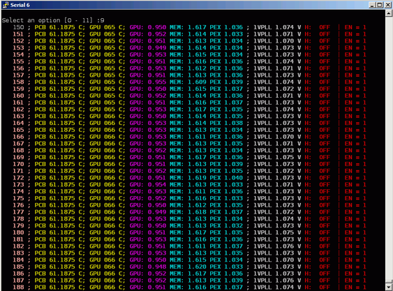
Useful menu items function are as below:
4. Set RGB data, which will let you configure LED RGB setting, just like Precision X does.
7. Monitors key voltages
8. Monitors GPU and PCB temperatures every second. Both GPU and PCB temperature can be measured in range from -64°C to +100°C. Works until any key press received
9. Monitors voltages, temperatures, and status 5 times a second, until any key press received
10. Self-explanatory setting, just like EVBOT, can be used to change GPU voltage. Entering value 0 will switch back to automatic control, 1-799 will return to menu without reverting to automatic control.
11-12. Power and heat monitoring
15. Activate or deactivate LN2 XOC heater coils. (works only if enabled by PCB mod)
Power tuning and controls
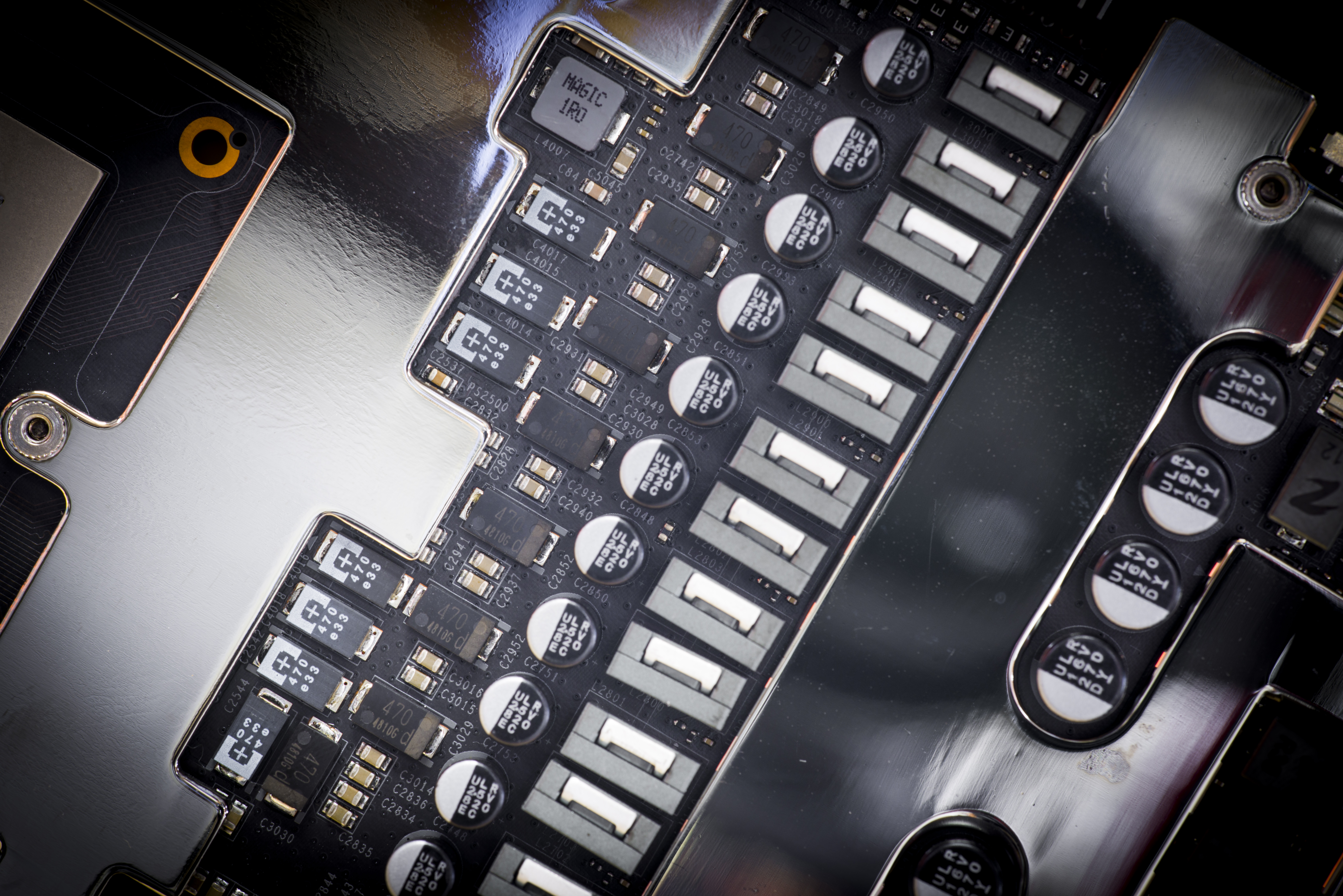
VRM on 980 Ti KPE take its roots from predecessor, 980 KPE, featuring next domains:
- NVVDD, GPU Voltage – IR3595A digital controller with 14-phases using latest generation IR3575M PowerIRStage
- FBVDD, Memory voltage – IR3570B digital controller with 3-phases using latest generation IR3575M PowerIRStage
- PEXVDD, Digital-controlled IR 10A SupIRBuck
- 1VPVDD, Digital-controlled IR 10A SupIRBuck
Each phase with IR3575M can deliver ~45 Amps of current with operation temperature +80 °C. And it’s unlikely to get so hot, as loading is spread across all phases. Thanks to exposed metal top of IR3575M, thermal heat is dissipated not just thru PCB copper, but also directly to VRM heatsink plate. It helps to keep VRM cool, and loss less power, so that improve margin on power target limit used by NVIDIA Boost function.
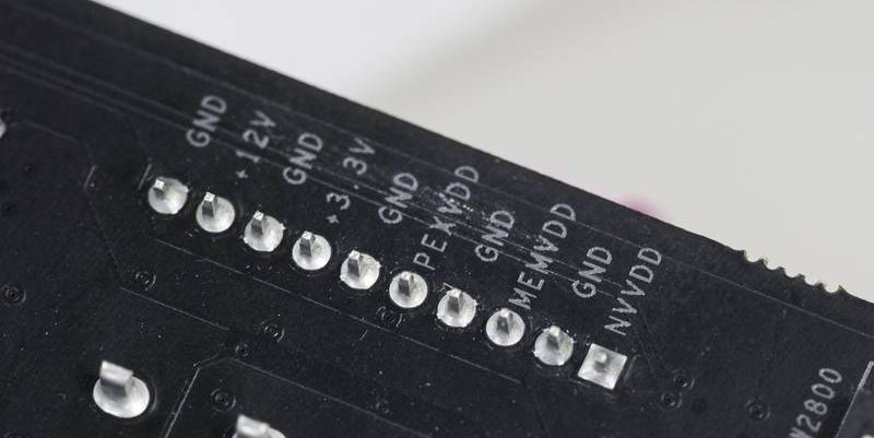
For voltage monitoring purposes EVGA GEFORCE GTX 980 Ti KINGPIN have 10-pin 2mm pitch PH-type connector near top PCB edge.
Pin definition as below:
| Pin 1 | GPU voltage |
| Pin 2 | Ground |
| Pin 3 | MEM voltage |
| Pin 4 | Ground |
| Pin 5 | PLL voltage |
| Pin 6 | Ground |
| Pin 7 | Onboard +3.3V power voltage |
| Pin 8 | Ground |
| Pin 9 | Onboard +12V PCIe power voltage |
| Pin 10 | Ground |
This pinout is same since GTX 680 era, so you still can use your ProbeIt setup if you had it done before. Also helpful labels are located on bottom side of PCB, near each connector pin to aid connection:
You can use bundled ProbeIt adapter to your usual multimeter probes, or in case you want to have custom cable connection to your specific meter, you can grab connector separately, for example here from Digikey.com . You will also need these contacts. If you want less pins (for example only 4 to monitor GPU and MEM voltage) you can get needed housings right here .
In addition to monitoring, this time around KPE card provides also extra hardware-based controls:
V-Tune switches
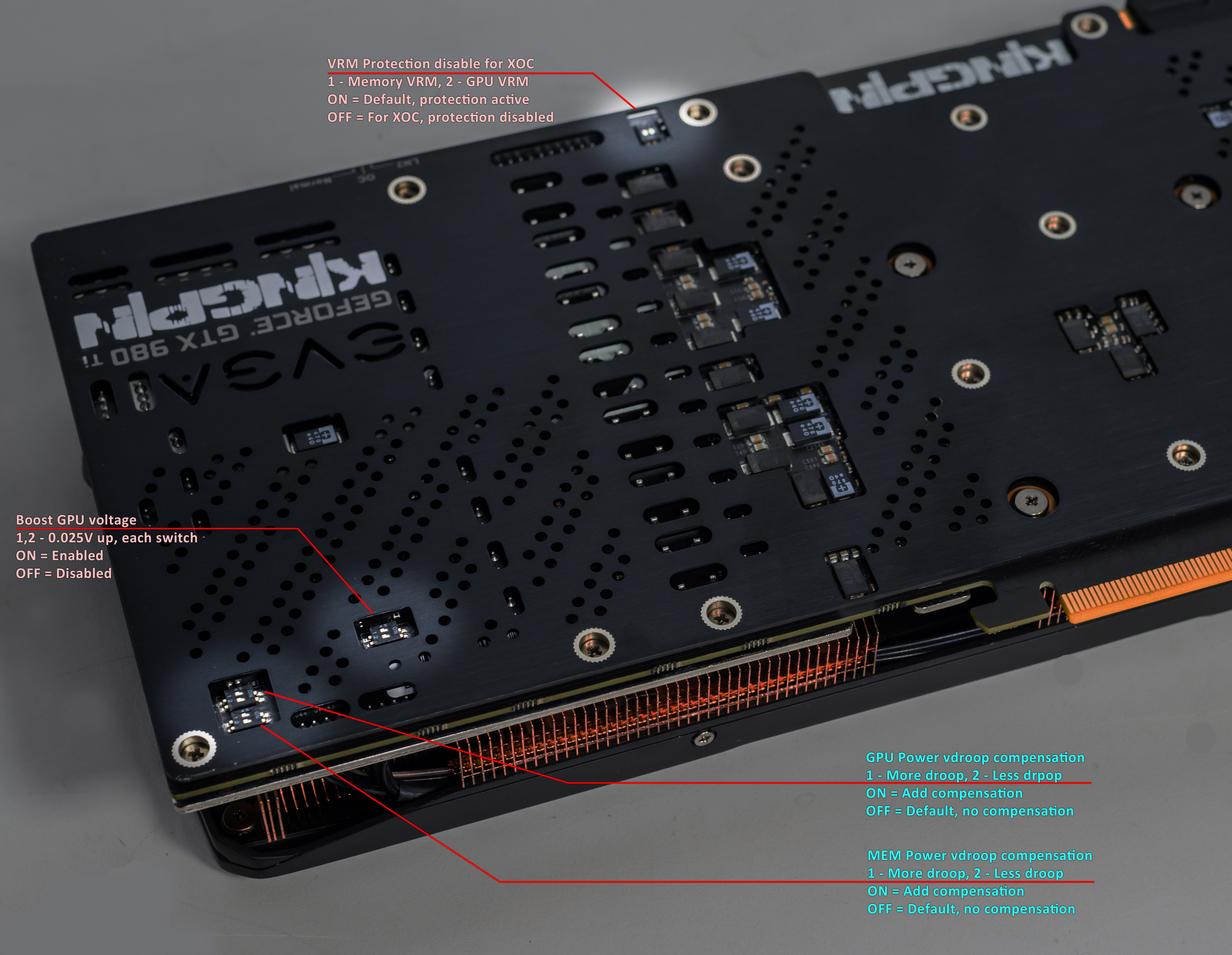
Top switch near ProbeIt port dedicated to LN2 operation, to eliminate possibility of voltage shutdown when benching with GPU temperatures below -100 °C. First switch position disable thermal protection for memory VRM, and second switch position does same for GPU voltage VRM.
Another switch on bottom lower side, can be used to boost GPU voltage +25 or +50mV above current setting. It’s different to software or EVBOT override control, as offset will be applied any time, even if GPU uses stock mechanism to control voltage. It could be useful if you wanted little bit extra voltage for everyday gaming, without any use of EVBOT or other voltage override methods. Each switch position at ON will add +25mV, so both will give +50.
Two switches near bottom corner dedicated for Vdroop fine tune. It’s can be used in ADDITION to EVBOT’s Vdroop enable/disable control, giving you at least 8 different Vdroop settings for GPU Voltage and three Vdroop settings for memory voltage.
EVBOT way
For lucky people who still have EVBOT controller, there is P55 EVBOT Firmware for EVGA GeForce GTX 980 Ti KPE
You can update your BOT with EVBOT Flash tool supporting Kepler & Maxwell GPU
This firmware allows you to control next settings:
| NVVDD | GPU Voltage, range is from 800 to 1850 mV |
| NVVDD Vdroop | can be enabled or disabled |
| NVOCP | OCP protection for LN2 benching, can be enabled or disabled |
| NVOC Mode | Should be set Extreme for LN2 benching, can be Normal or Extreme |
| NVPWM | Sets PWM frequency for GPU VRM, from 750kHz to 1333kHz |
| FBVDD | Memory voltage, from 1500 to 2100mV. Best for LN2 around 1850-1900mV |
| PEXVDD | PCIe PLL voltage, from 1045mV to 1400mV |
| 1VPVDD | GPU PLL voltage, from 1065mV to 1300mV |
| VIDVDD | Clock PLL voltage, from 1045mV to 1500mV |
This is it, these settings and ranges are more than enough to max out GM200 GPU, even on LN2 cooling.
DIY way
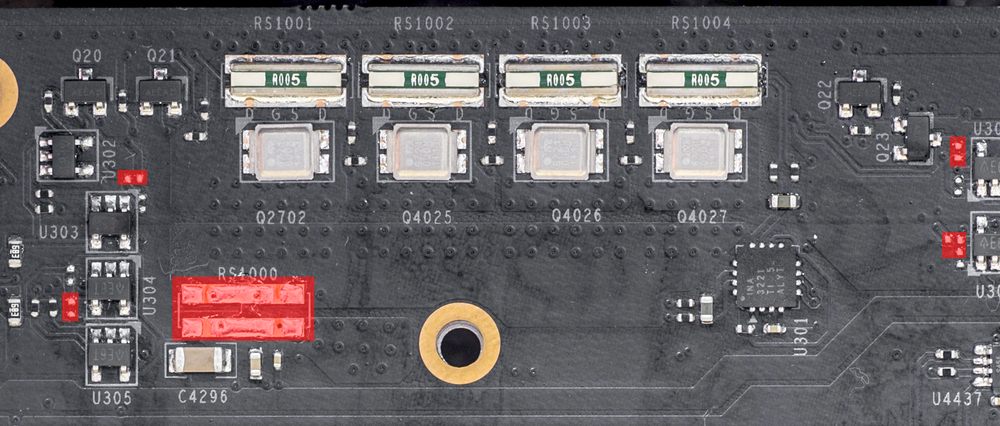
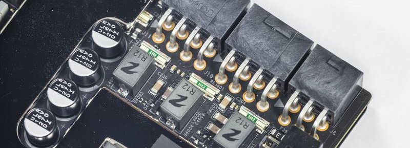
Same as 980KPE, there are pads for commonly used 3296W-type trimpots.
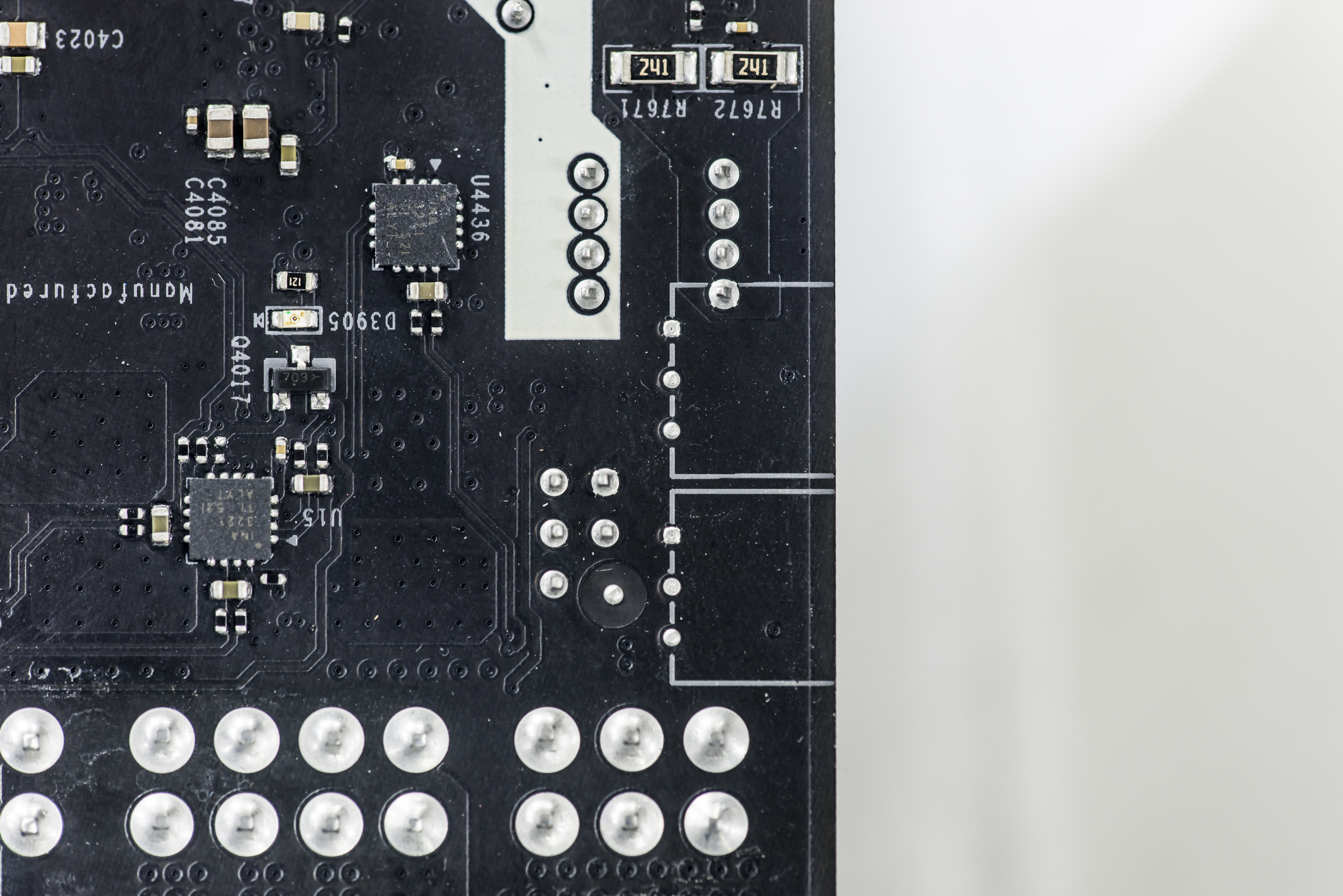
To activate this mod, put two shorts in area marked on photo below.
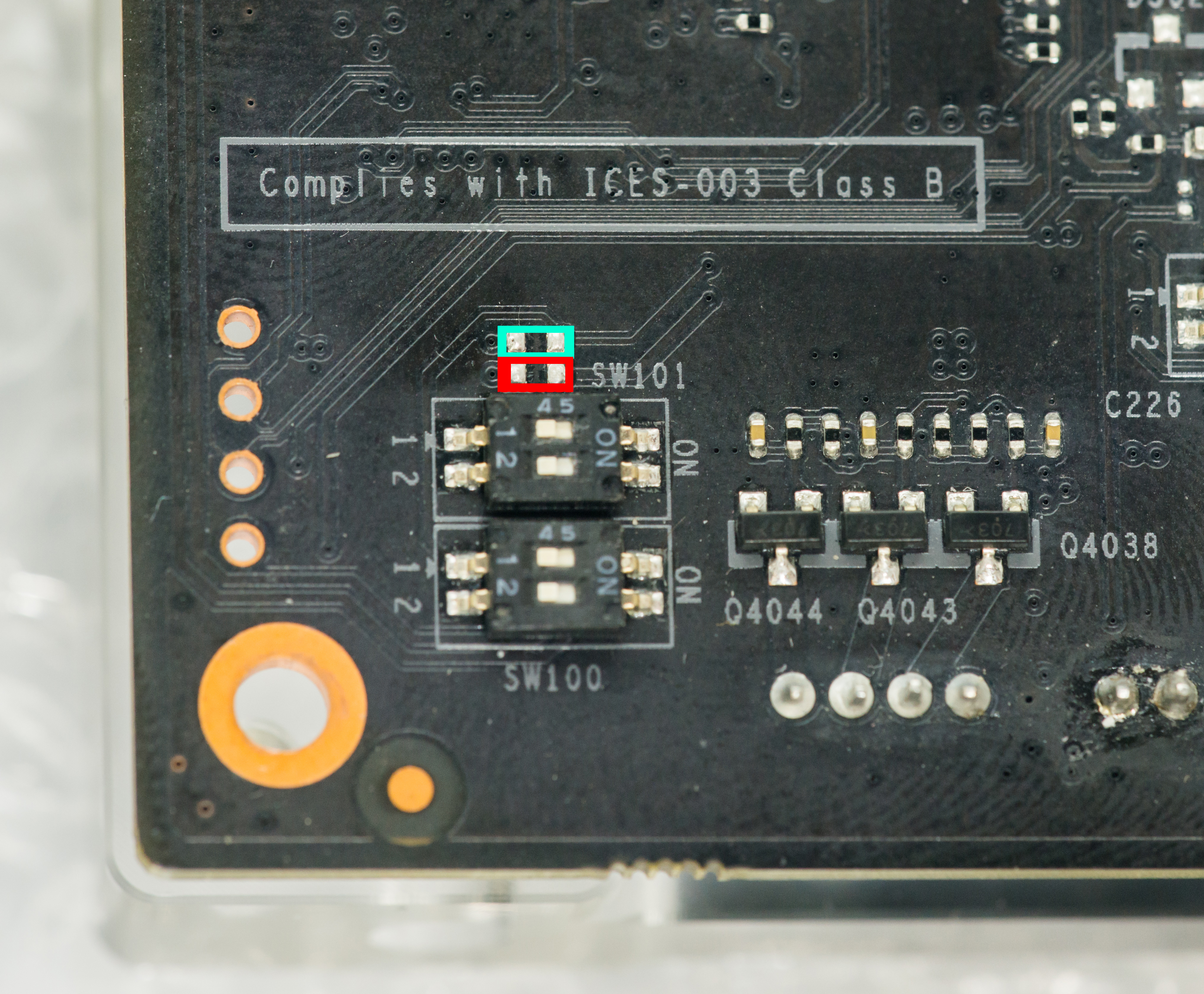
Shorted pads in cyan box enable memory voltage trimmer, while red pads short enable GPU voltage trimmer.
Do not short red to cyan, as these pads drive different signals.
Now you can add trimmers, like on photo example:
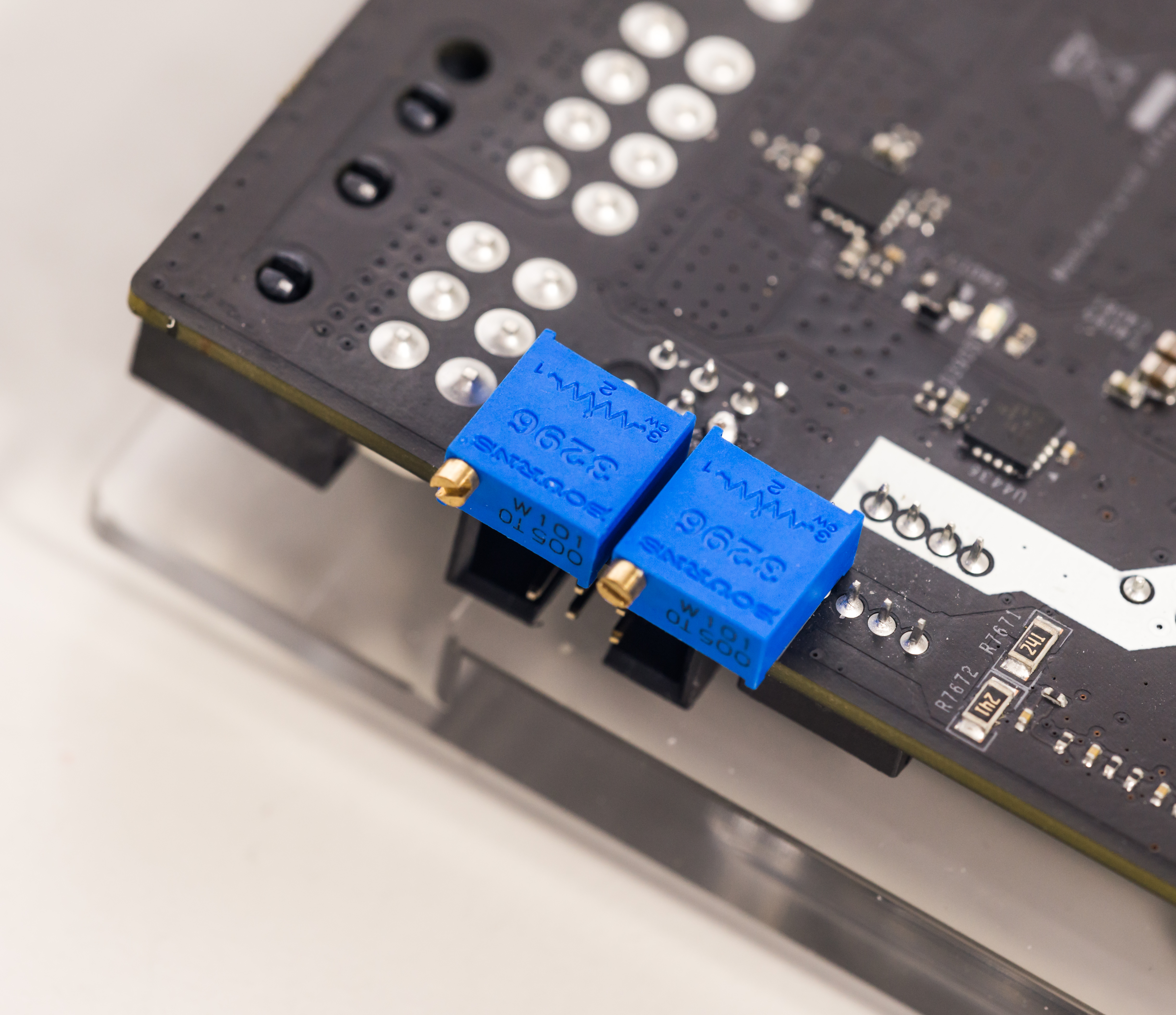
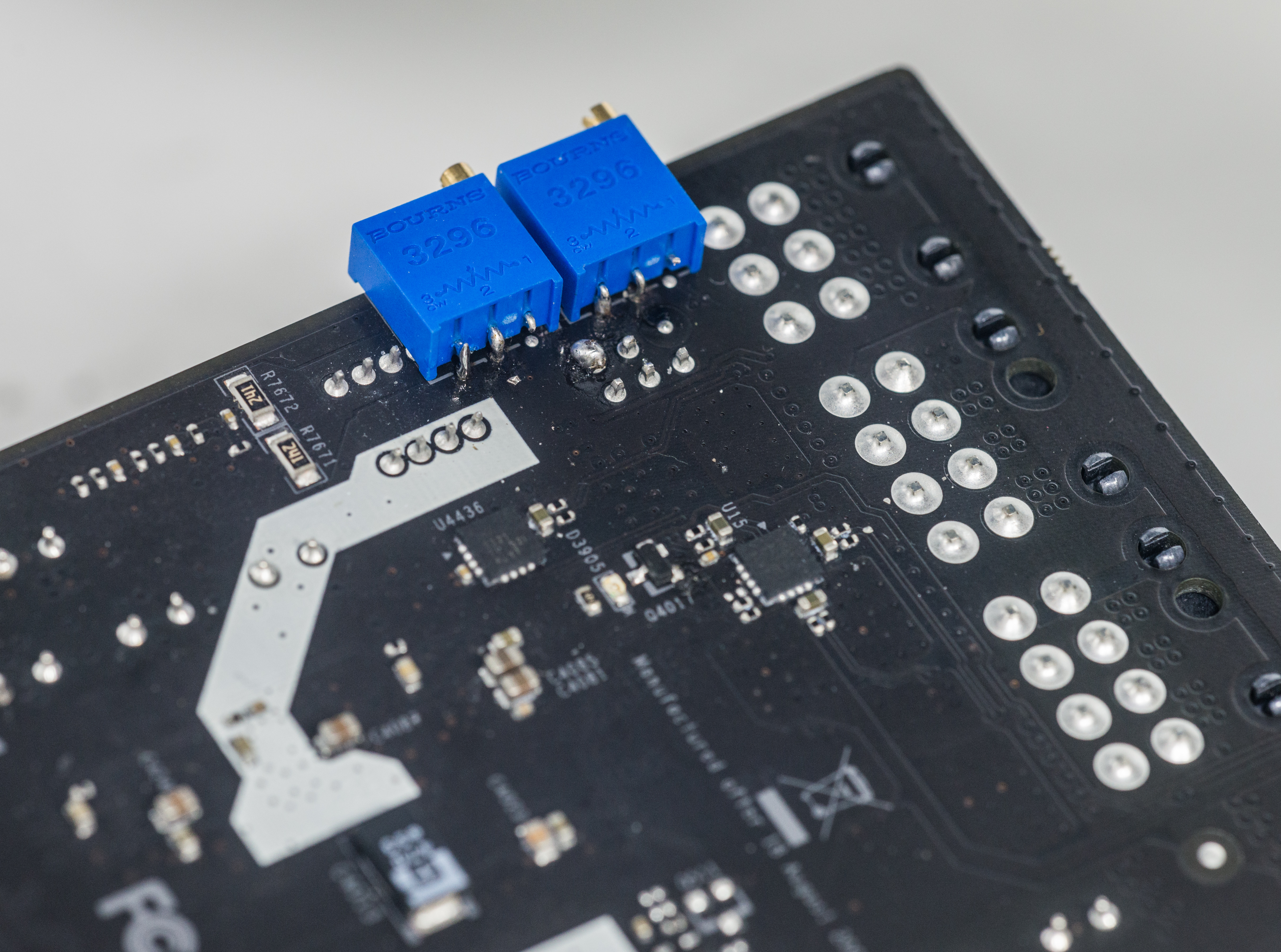
For GPU (top) should use 100 ohm resistance , like 3296W-1-101ALF.
Top trimpot (closer to 6-pin power plug) is for increasing GPU voltage (lower resistance increses voltage).
For Memory (bottom) should use 1 kOhm resistance, like 3296W-1-102LF.
Bottom trimpot is for increasing MEM voltage (lower resistance increases voltage).
Adjusting resistance down to 550 ohm will increase memory voltage to ~1.7V.
Software way
FTW12345’s little tool 2.1.2 also working on 980 Ti KPE.
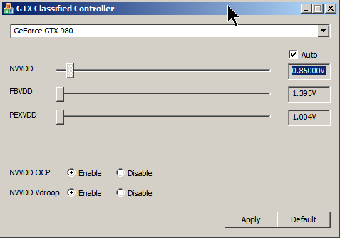
There is one drawback for software, as settings can be adjusted any time, and will keep but will be reset on power cycle (card power turn off/turn on).
So if your system shutdown, then all voltages and OCP/Vdroop setting will be reset to default.
That’s one of reasons why other ways, like EVBOT/RPI or hardware mod are prefferable for hardcore LN2 benching.
Raspberry Pi way
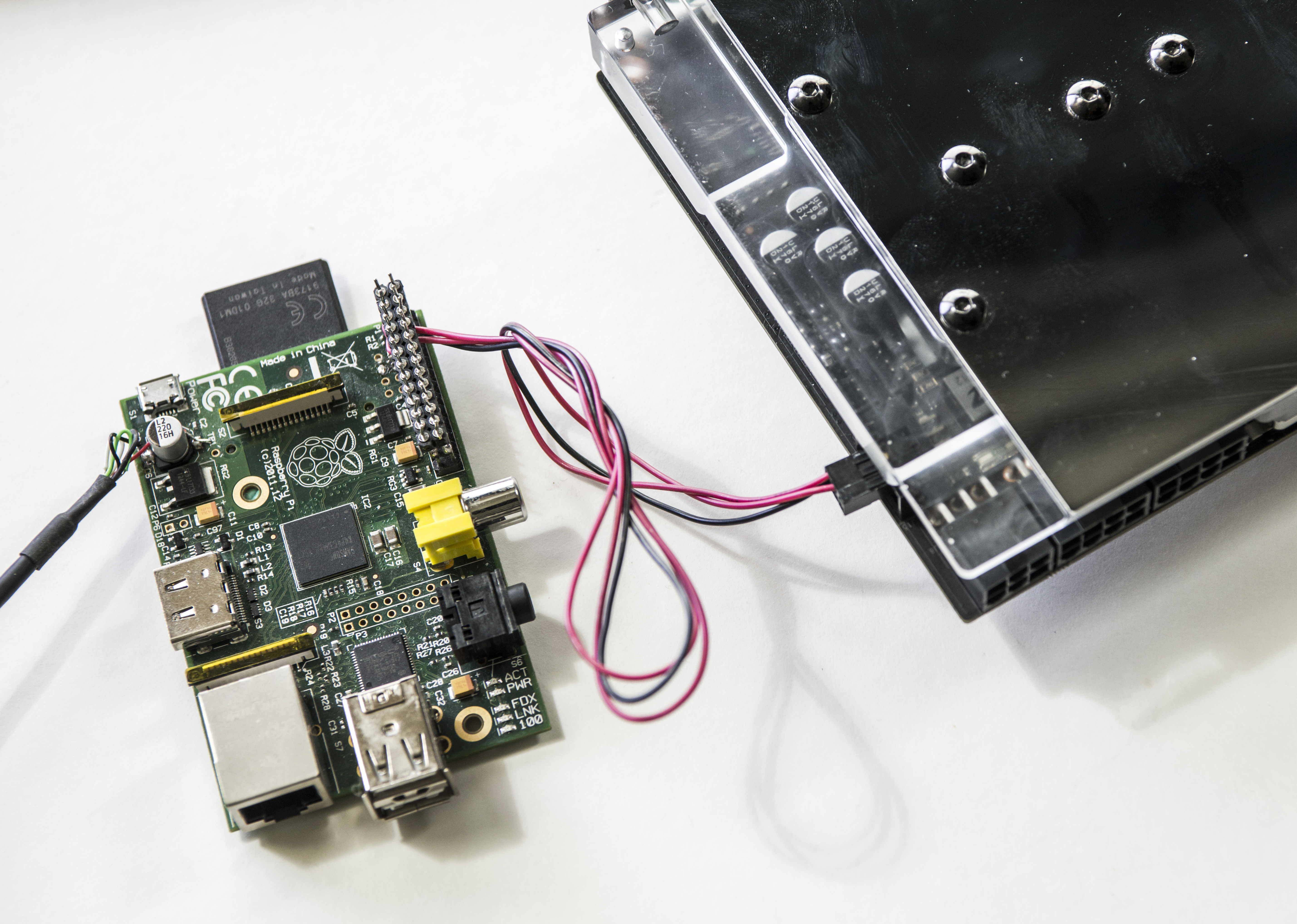
You can use widely available RPI to set voltage via EVBOT port on the card. To do so you will need connect three wires from Raspberry Pi to VGA’s EVBOT connector.
| Raspberry Pi signal name | Raspberry Pi Pin | EVBOT Port pin |
| Ground | Pin 9 on header P1 | Pin 6 on header J15 |
| SDA | Pin 3 on header P1 | Pin 5 on header J15 |
| SCL | Pin 5 on header P1 | Pin 3 on header J15 |
EVBOT Pinout is next (looking at connector’s face):
| Pin 1 | |
| Pin 3 SCL | Pin 4 |
| Pin 5 SDA | Pin 6 GND |
After connection, check that all pins are correct and try to detect card on RPI.
root@raspberry-pi:~# i2cdetect -y 1
     0  1  2  3  4  5  6  7  8  9  a  b  c  d  e  f
00:          -- -- -- -- -- 08 -- 0a -- -- -- -- --
10: -- -- -- -- -- -- -- -- -- -- -- -- -- -- -- --
20: -- -- -- -- -- -- -- -- -- -- -- -- -- -- -- --
30: -- 31 -- -- 34 -- -- -- -- -- -- -- -- -- -- --
40: -- -- -- -- -- -- -- -- -- 49 -- -- -- -- -- --
50: -- -- -- -- -- -- -- -- -- -- -- -- -- -- -- --
60: -- -- -- -- -- -- -- -- -- -- -- -- -- -- -- --
70: -- -- 72 -- -- -- -- --
Correct output is shown on terminal capture above.
Now, you can run download tool here to your Pi and run it to set GPU voltage.
root@raspberry-pi:/home# ./tikpe_vcore
/******** Manual VID setting tool :) **********/
Voltage monitored = 1000 mV
 Enter voltage, in millivolts (800...1850): 1000
Voltage monitored = 1000 mV
 Enter voltage, in millivolts (800...1850): 1100
Voltage monitored = 1100 mV
 Enter voltage, in millivolts (800...1850): 1200
Voltage monitored = 1197 mV
 Enter voltage, in millivolts (800...1850): 1300
Voltage monitored = 1293 mV
 Enter voltage, in millivolts (800...1850): 1400
Voltage monitored = 1388 mV
 Enter voltage, in millivolts (800...1850): 0
Incorrect voltage input!
Here voltages in 100mV steps were entered, and actual readout values for input, output voltage after each change also reported back.
Watercooling compatibility
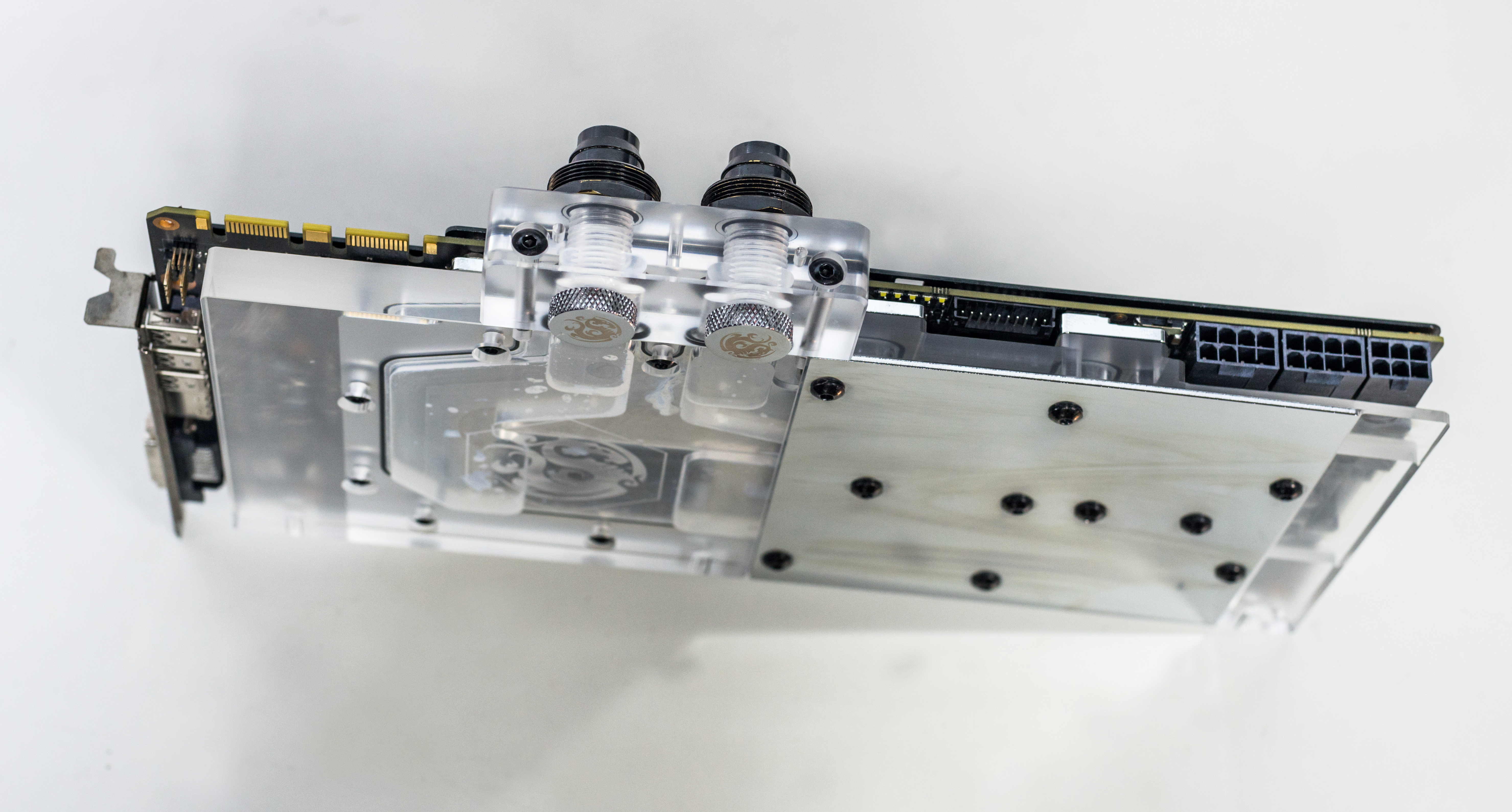
Bitspower 980 KINGPIN waterblocks are compatible with GTX980Ti KPE as well, with minor limitation:
Due to different memory chip layout – few memory chips will not be in direct contact with block. That’s not big issue from performance, as memory is not power hungry device and does not need direct active cooling. You can add thermal pad between extra chips and block, so nothing to worry about there.
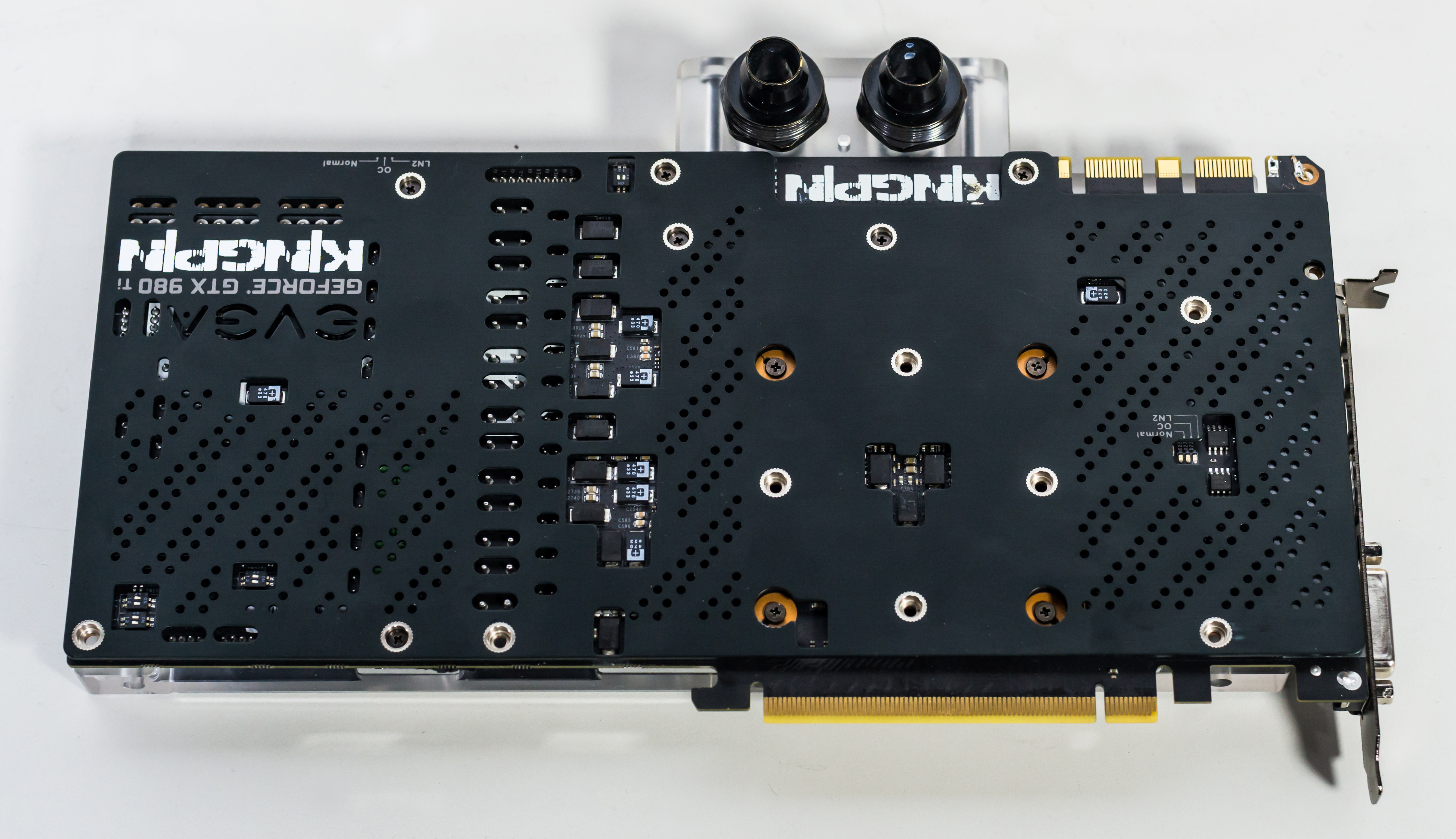
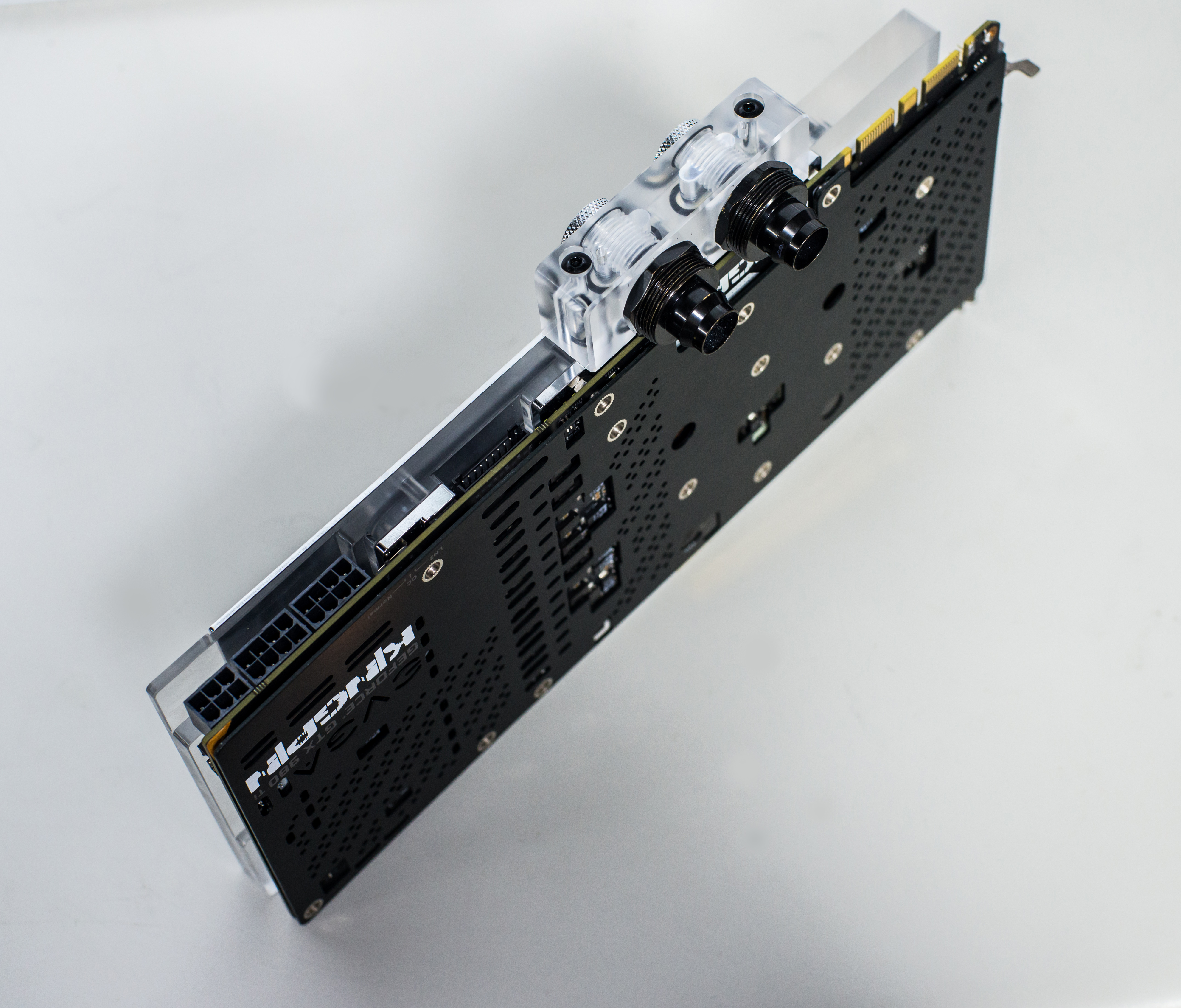
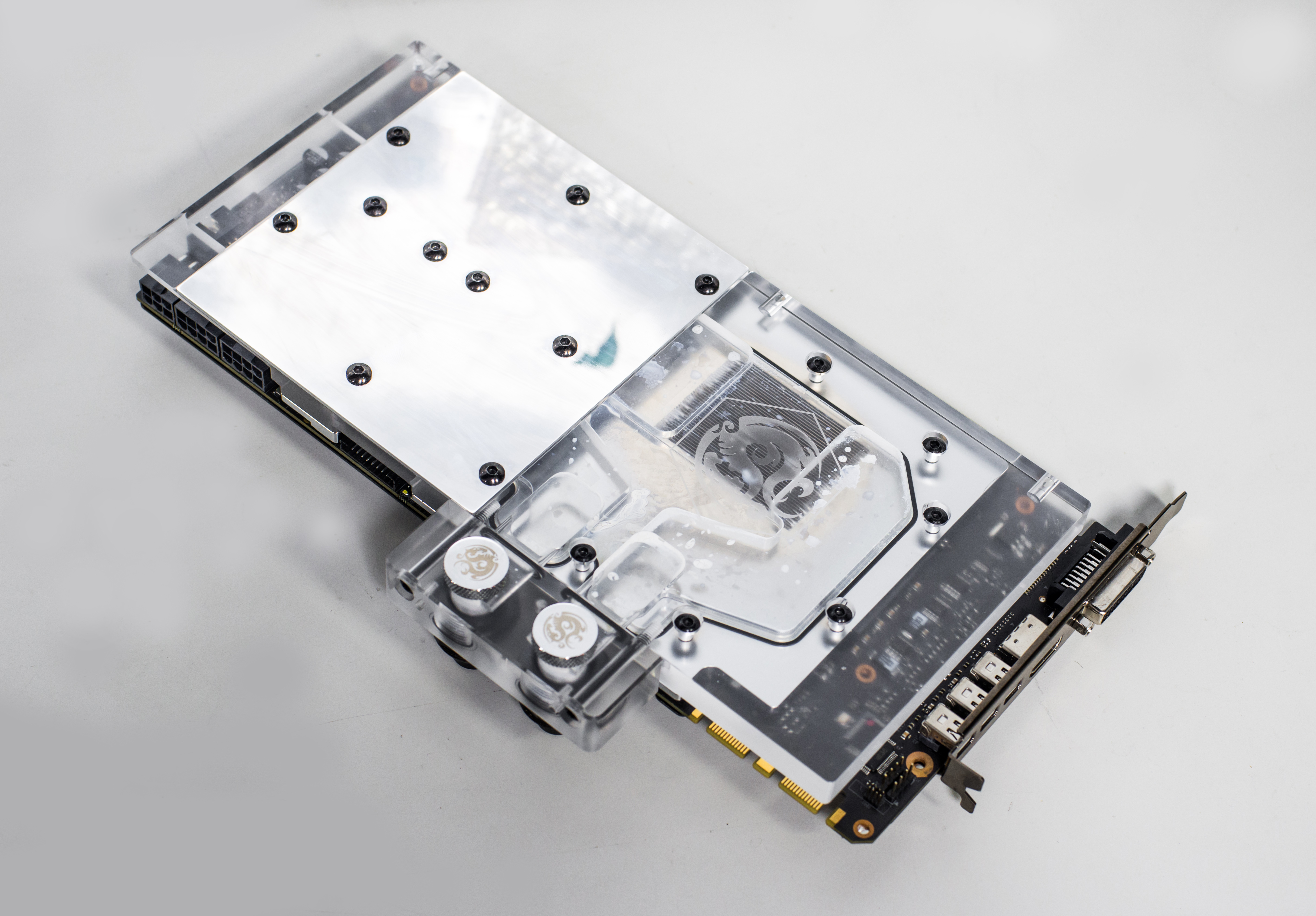
Here’s example with BP 980KPE block installed on 980 Ti KPE:

We will use native EVGA KPE backplate, to keep access for switches and LEDs. In such case stock screws should be used to mount block, as Bitspower screws are made longer to fit with thicker BP backplate.
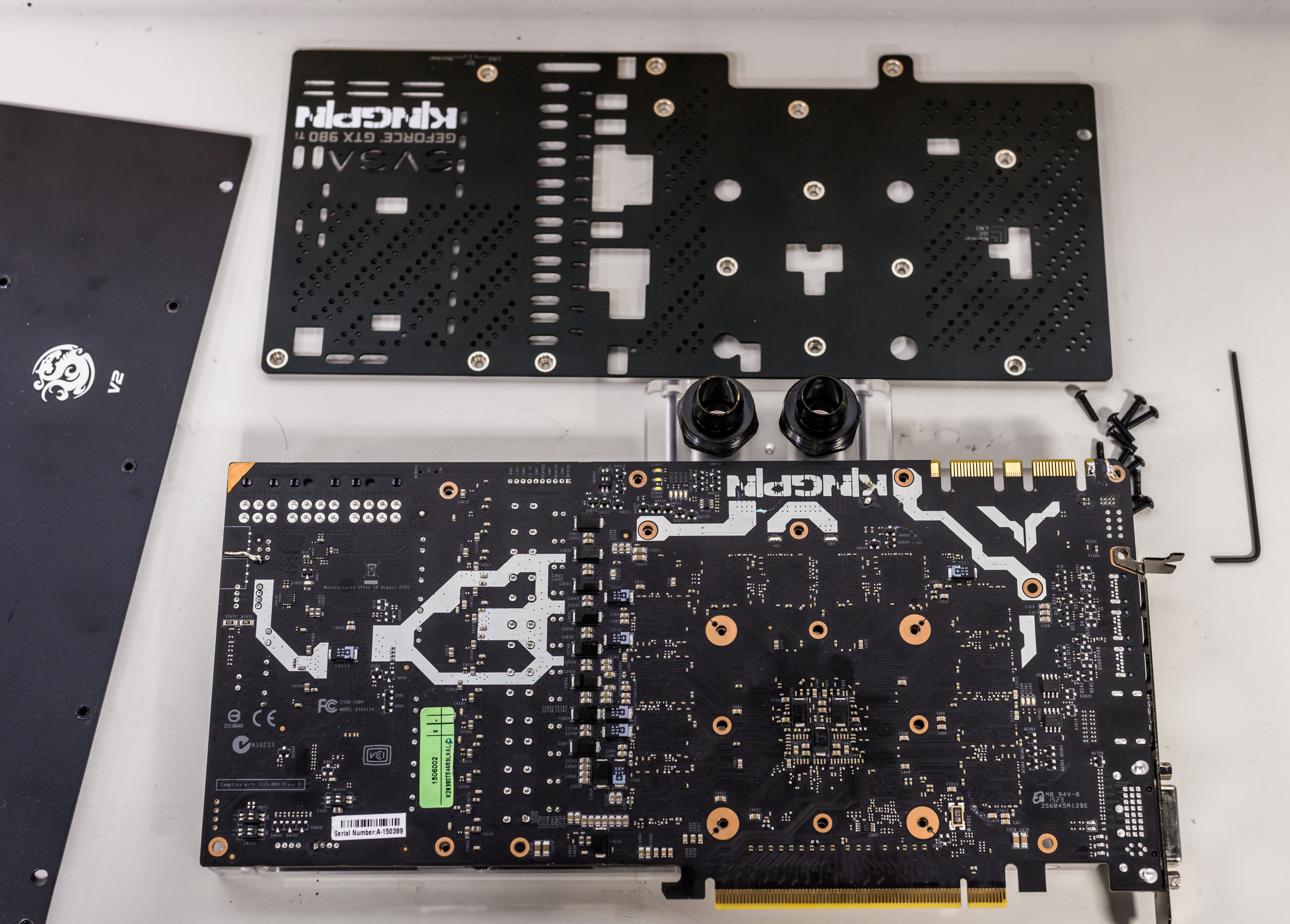
Installed block, front & back side
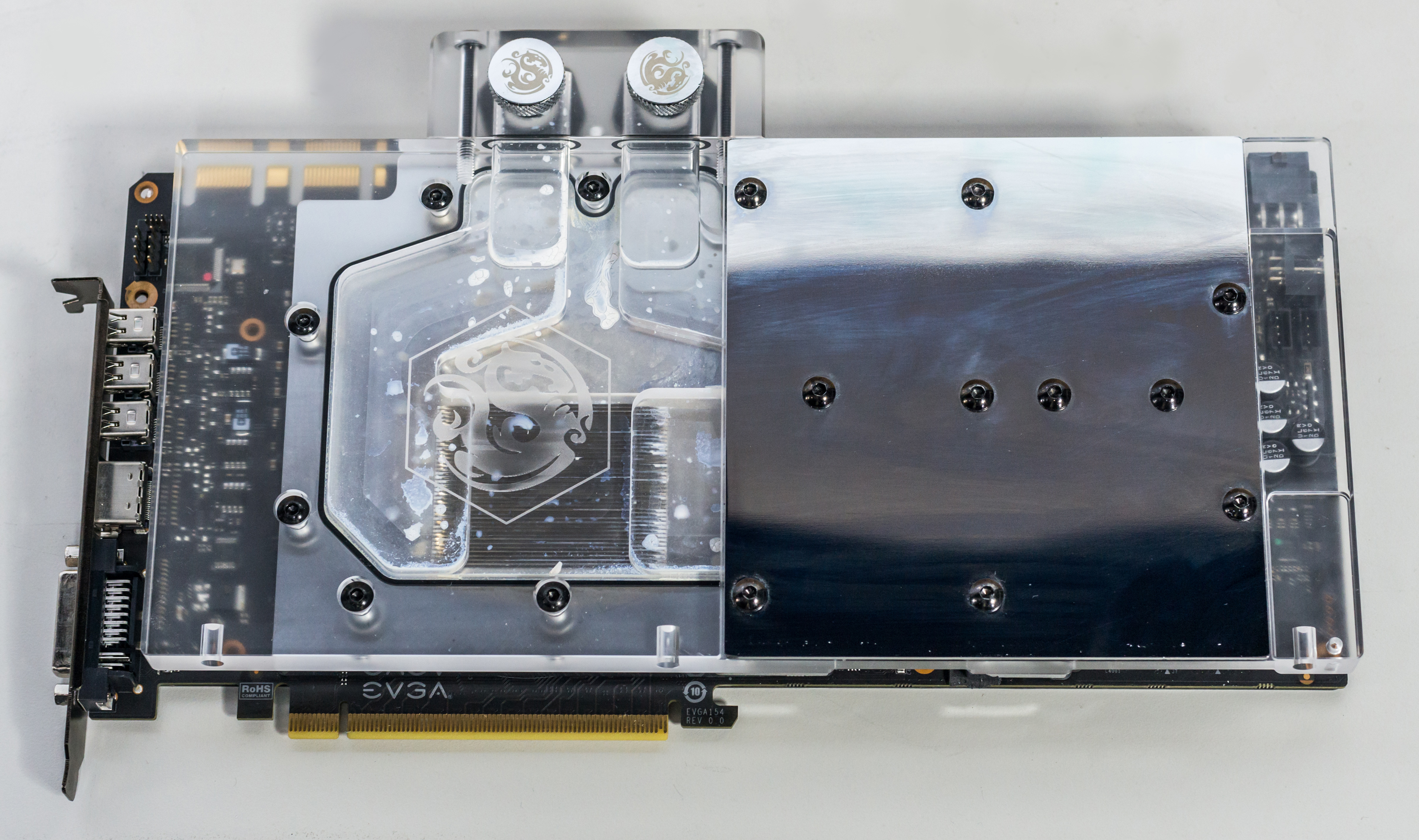
BP block is not exactly single-slot, like EK, but still much thinner than stock fansink solution.
DIY RGB lights for waterblock setup (BP) or casemodding
Bitspower waterblock have spots for 5mm LEDs on bottom edge, so it’s a perfect candidate for these RGB LEDs , for casemodding and custom chassis systems.
To connect LEDs, we use same connector type as ProbeIt , but with 4-pins only.
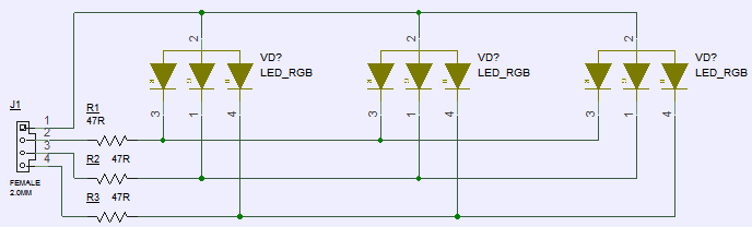
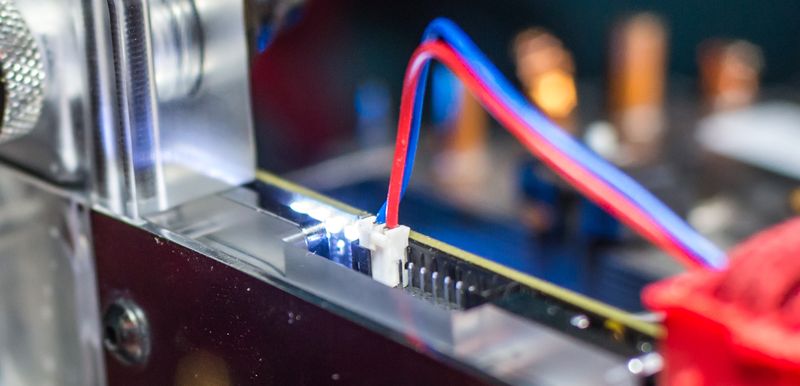
Following simple schematics as shown, connect your custom RGB LEDs with 20-47 Ohm resistor in series. I had no 5mm RGB LEDs, so used 5050 SMD ones instead.


Now you can use Precision X to adjust LED settings. As example, to set rainbow effect, cycling all colors, use Demo2 setting:
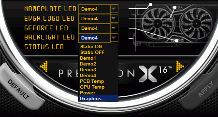
Result could be similar to photo below:
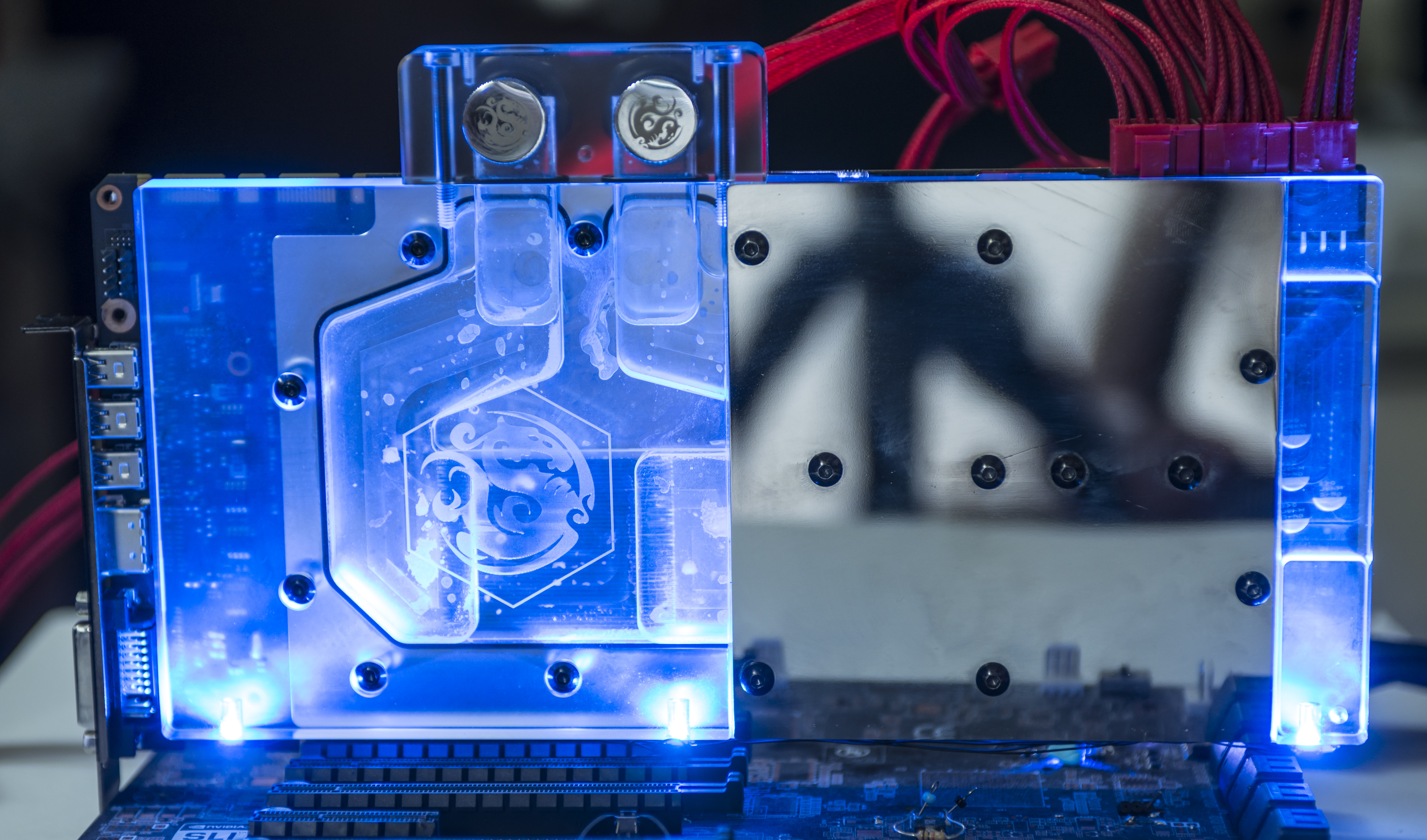
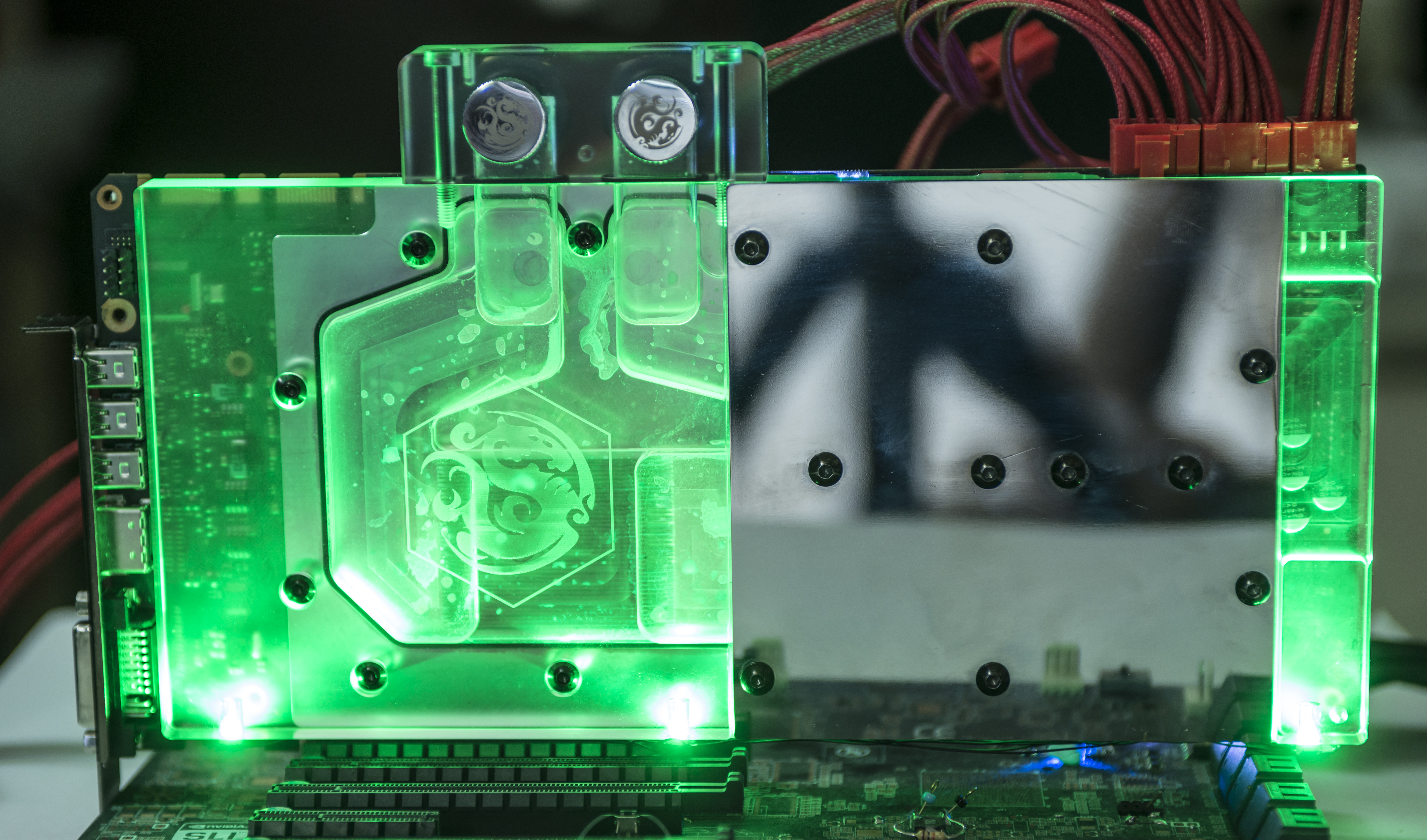


You can connect each LED to separate port (connectors J17,J18,J19) to control LEDs individually. Only your imagination is a limit for color scheme.
Here’s prompt YouTube video on click showing completed mod with three RGB LEDs fixed on BP block and controlled by RGB connector on PCB.
Fix LED blinking issue for early cards when running hot
Some cards may have random RGB LED blinking if PCB temperature is higher than +70°C.
This issue can be fixed by user update, by following instructions listed in steps below.
Tools required:
- Standard USB Bracket or 2.54mm (0.1”) pitch wire harness with two 4-contacts plugs.
- USB Cable Type-A to Type-A in case of using Standard USB Bracket
- Thin twizzer to modify bracket pinout
- Software update tool and firmware V12
- Philips screwdriver
- Laptop or other PC if system with VGA don’t have OS/cannot boot. VGA card need only power needed to update code. (optional)
Estimated time required: 30 minutes.
STEP 1. Prepare update cable and toolkit
Download and copy tool and firmware file to local folder on your drive (for example, C:/5998_FW).
Get standard dual-port USB 2.0 bracket for chassis.
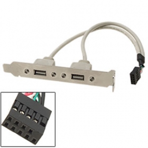
Change pinout as on diagram below:
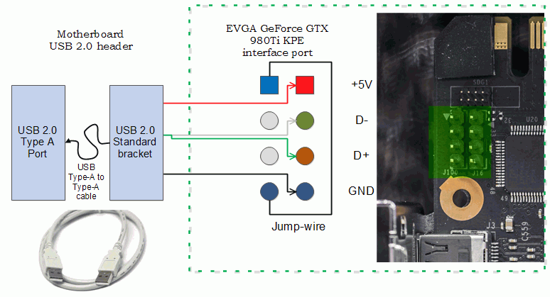
To do so:
- Remove pins 1 (Red wire),3 (White wire),5 (Green wire),7 (black wire) from dual-row header plastic.
- Install jump-wire to position 1-7.
- Cut free red,white and green wires, as these not needed
- Cut extra plastic housing for pins 9 and 10, using paper blade knife.
End result should look like this:
With Type-A cable:
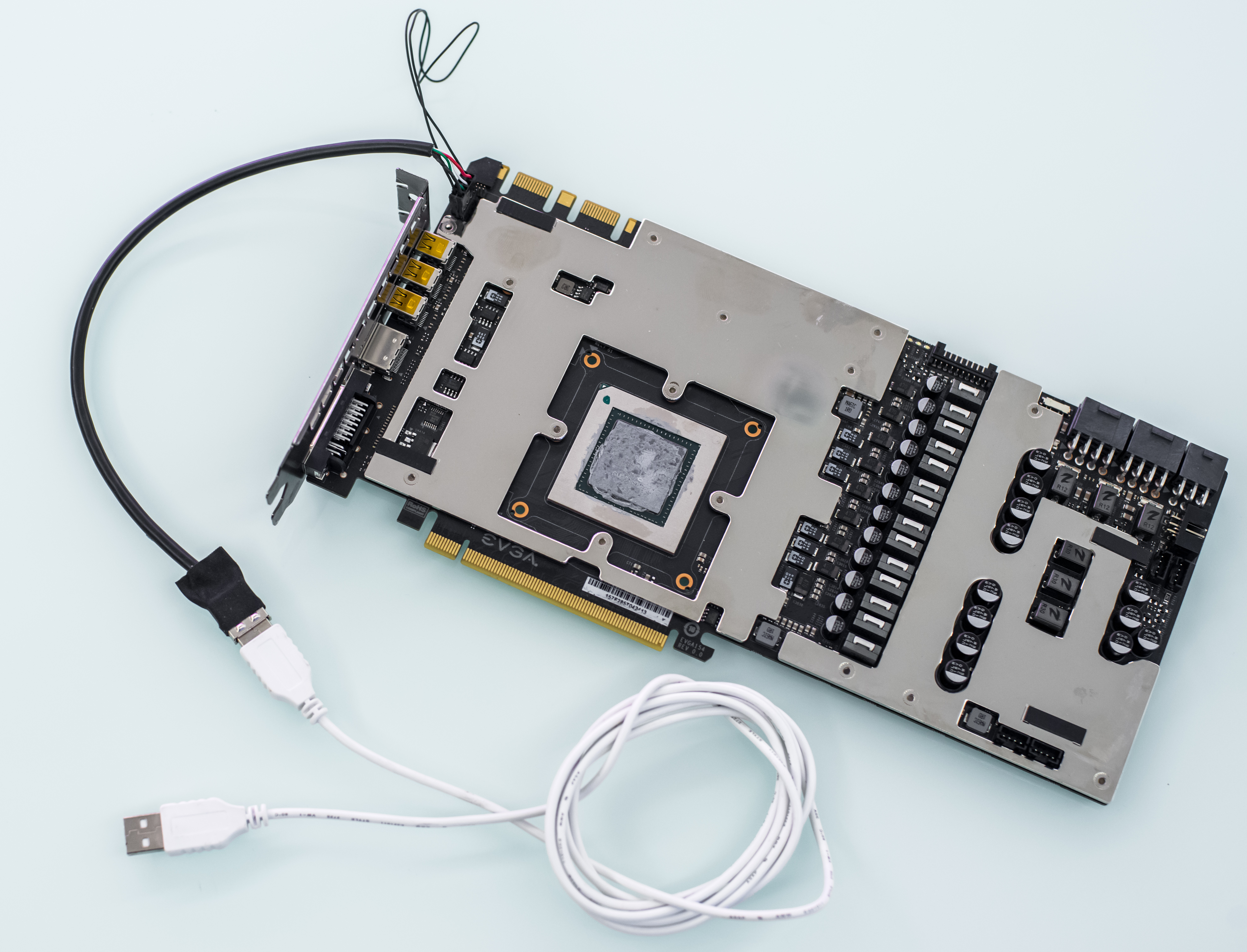
Fansink not shown for clarity only.
Alternative STEP 1b.
You can use standard 2.54mm pitch cable to connect port on VGA to your motherboard USB 2.0 chassis pin header.
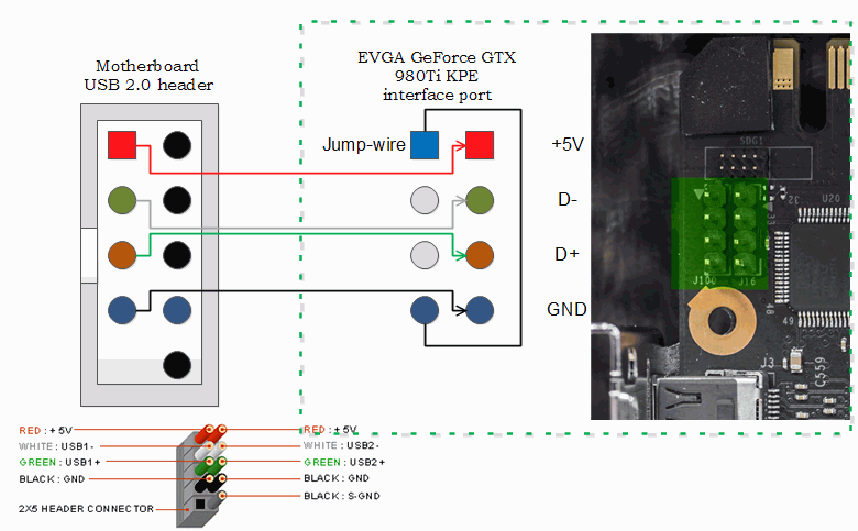
In this case you can just use direct header-to-header connection to MB’s USB port:
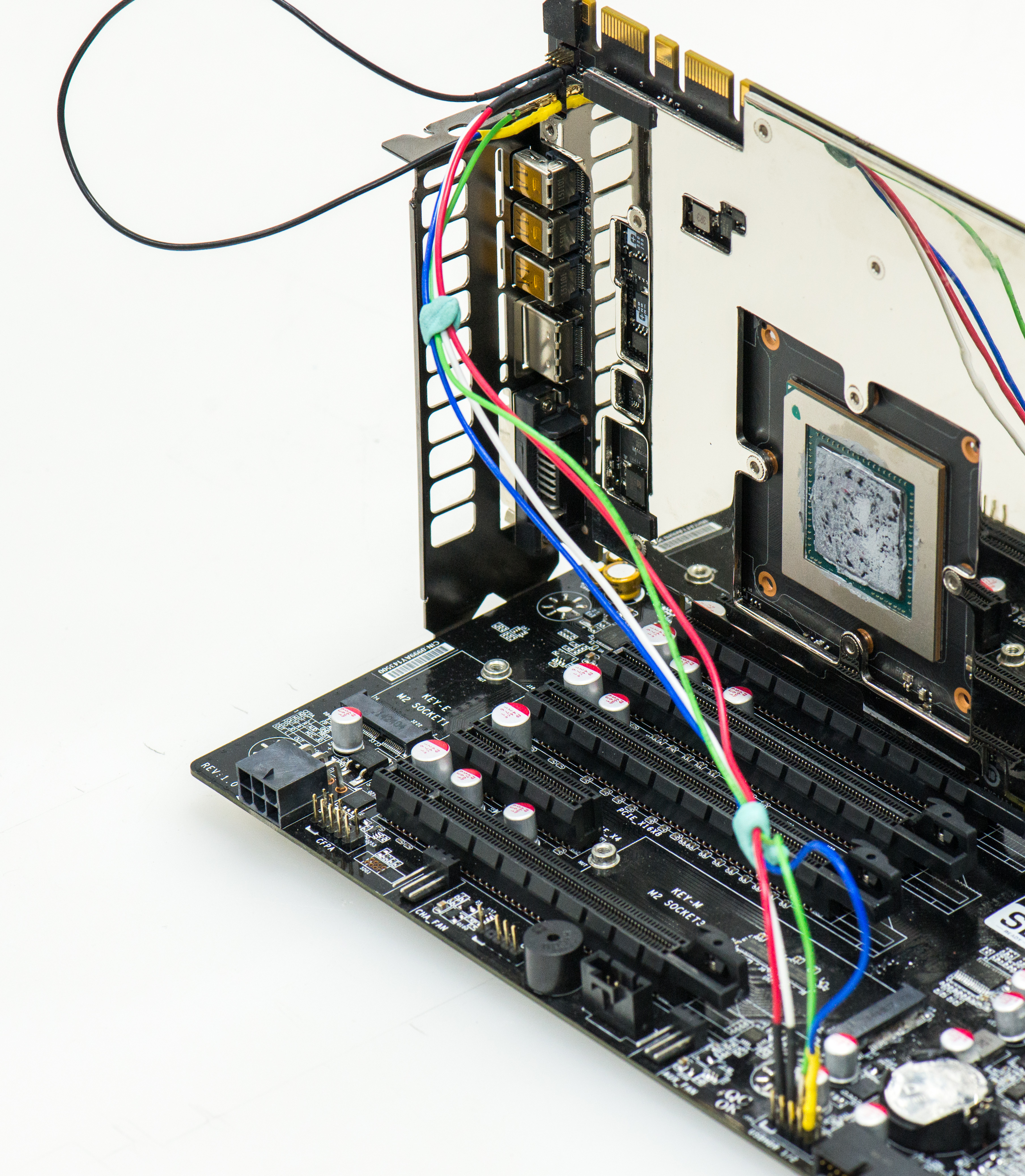
MB side:

Fansink not shown for clarity only.
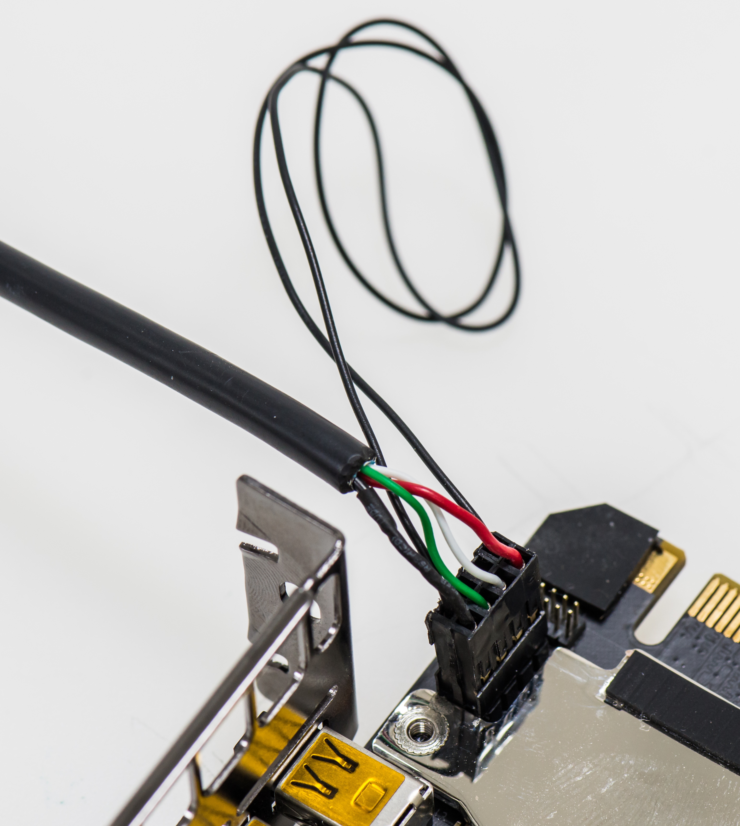
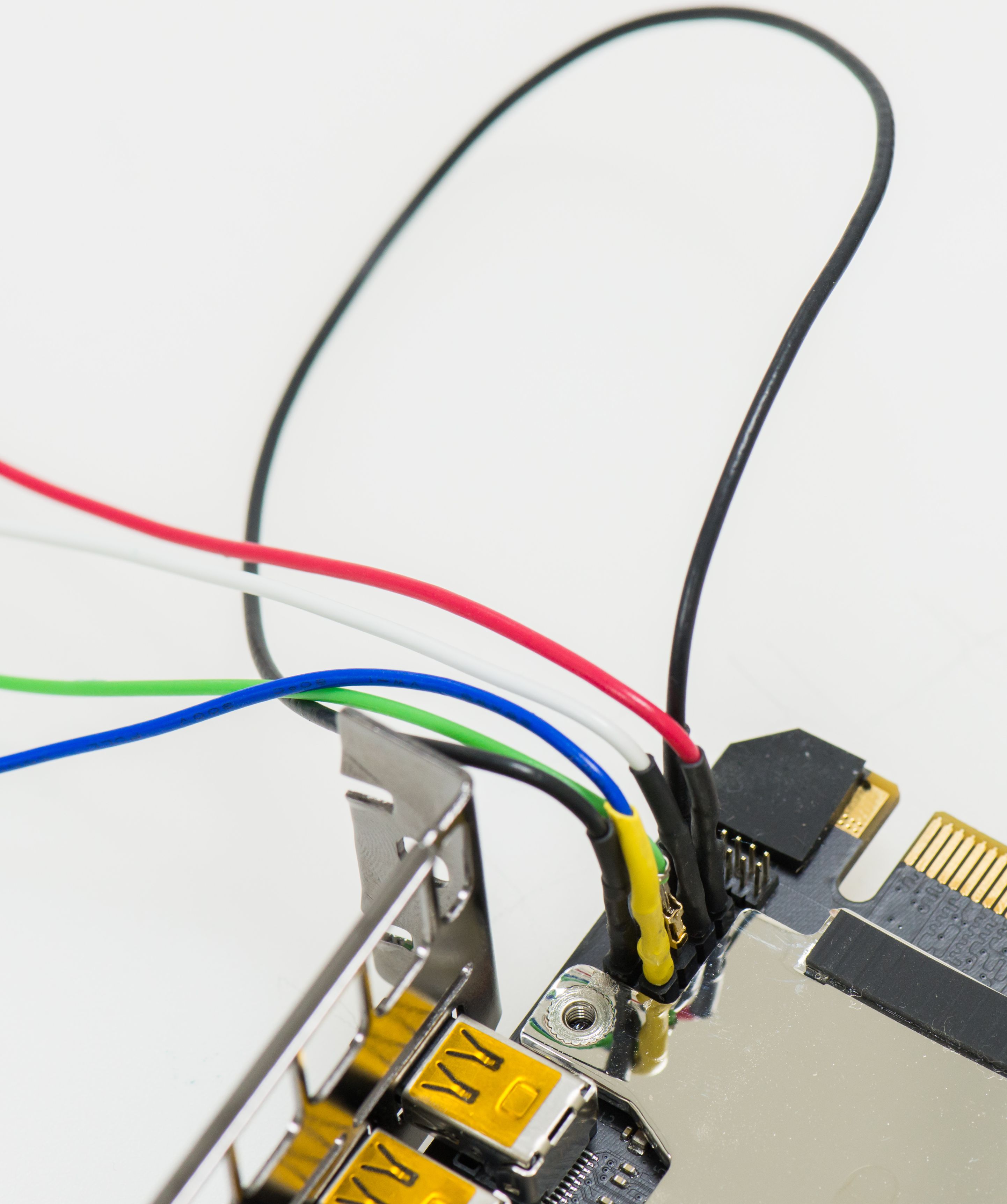
STEP 2. Connect cable to VGA card header
Use Philips screwdriver to remove fansink (need only unscrew four big screws for thermal module, no need to touch backplate mounts).
Now plug header end to VGA card port near SLI, like shown on diagrams above.
Carefully install fansink thermal module back. Thermal pipe will push against cable, but that’s OK.
Make sure fansink sits flat and firm on card GPU. Fasten 4 screws and install card into system.
STEP 3. Power on and boot Windows normally.
VGA card now will be in update mode, and RGB LED would not function at this moment. Five status LEDs will be also lit bright white.
It’s recommended to keep system at stock clocks, to ensure proper update without interrupt.
STEP 4.
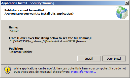
Unpack WinISP.zip and run setup.exe
If security warning pop-up, you can just ignore it and let it go by pressing Install button.
After successful installation, just run setup.exe once more.
Simple GUI will be opened.
Load firmware binary by pressing button “Select firmware” and choose proper path to 5998 KPE firmware V12
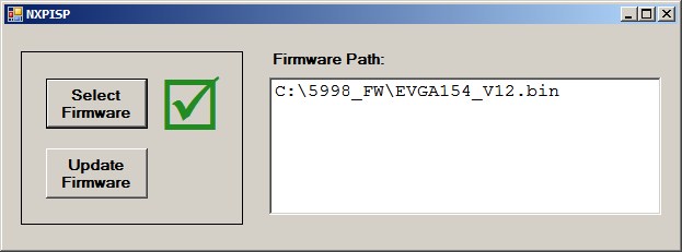
Green mark will be shown near button if firmware loaded correctly.
STEP 5.
Now press “Update Firmware”
Card will be programmed with new code automatically. This takes just few seconds to complete.
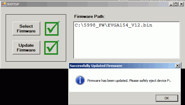
If update fails, retry again from checking connection at STEP 2.
Safely eject virtual disk drive and power down PC. Disconnect cable from card. Update procedure is now complete.
All newer cards are coming already with updated firmware, so this fix only for 980Ti KPE cards sold before September 2015.
If your card was used for extreme overclocking and have heater circuitry enabled, you must disable it prior to doing this fix for a safety measure. This can be done by removing RS4000 short.
This fix does not affect any overclocking aspects of the card.
Feel free to share link to this guide, but keep links and references intact, as guide might be updated in future.
© Vince “K|NGP|N” Lucido & Illya “TiN” Tsemenko
Projects like this are born from passion and a desire to share how things work. Education is the foundation of a healthy society - especially important in today's volatile world. xDevs began as a personal project notepad in Kherson, Ukraine back in 2008 and has grown with support of passionate readers just like you. There are no (and never will be) any ads, sponsors or shareholders behind xDevs.com, just a commitment to inspire and help learning. If you are in a position to help others like us, please consider supporting xDevs.com’s home-country Ukraine in its defense of freedom to speak, freedom to live in peace and freedom to choose their way. You can use official site to support Ukraine – United24 or Help99. Every cent counts.
Modified: May 26, 2022, 4:45 a.m.
References
- Uncorking reference EVGA GeForce GTX 980 for overclocking
- P55 EVBOT Firmware for EVGA GeForce GTX 980 Ti KPE
- Override NV Power limit by hardware
- EVGA Precision X OC toolkit
- EVGA GeForce GTX 980Ti KINGPIN Pics
- EVBOT Flash tool supporting Kepler & Maxwell GPU
- PDF-version of this article
- PDF-variant of this article, Russian language
- Guide for GTX 980 XOC modifications
- Adjusting voltage on EVGA EPOWER Classified module
- PuTTy terminal