- Intro
- Warnings & Disclaimers
- Raspberry Pi Overclocking methodology
- Frequency and voltage control settings
- Benchmark software setup
- Base-line stock results
- Overclocking results
- Summary and conclusion
Intro
ARM today is one of the most popular architectures in embedded systems and used in many applications and fields. Modern ARM-based systems have all the means to run fully-featured Linux OS, and allow quick start on own project development even without any background knowledge in hardware design. Software developers now can build own devices without even touching the soldering iron.
Compact (85 × 56 mm) Raspberry Pi single-board computer represent this concept as affordable educational platform. Here at xDevs.com various versions of Raspberry Pi are already widely used as test equipment controllers and live data-logging platform. Low cost (around $40 USD for fully-featured Raspberry Pi 3) and compact size allow easy adding of standalone modules for running different experiments, and invisible to total project budget since involved test equipment often costs many times more. Separate traditional PC or even laptop for such needs would occupy too much space, power and programming effort, as low level interfaces such as I2C, SPI are rarely available without additional hardware.
I’m well used to traditional desktop computer performance tuning and overclocking as a hardware enthusiast. Overclocking can take many forms and shapes, from useful everyday boost of few hundred MHz (think of tuning car engine to get better acceleration performance) to insane cryo-cooled rigs for international OC competitions (drag-racing cars with jet engines, no less). After few years of pushing performance of desktop computer as a hobby it become part of my daily profession, designing products that implement overclocking features and ability at their core, such as high-performance PC graphic cards and high-performance motherboards for Intel CPUs. To explain some concepts and design features that help users to achieve better overclocking many detailed OC guides were posted, such as here or here. Hardcore overclockers even create demand for special power supply modules that allow use of higher voltages to gain that last bit of performance possible.
Overclocking is not limited just to personal computer, same concept applies well for nearly any digital system, including mobile processors and embedded SOC devices, such as Raspberry Pi 3. It is not new, other people were already successfully overclocking their Pi1’s years ago, yet it’s still fun to do.
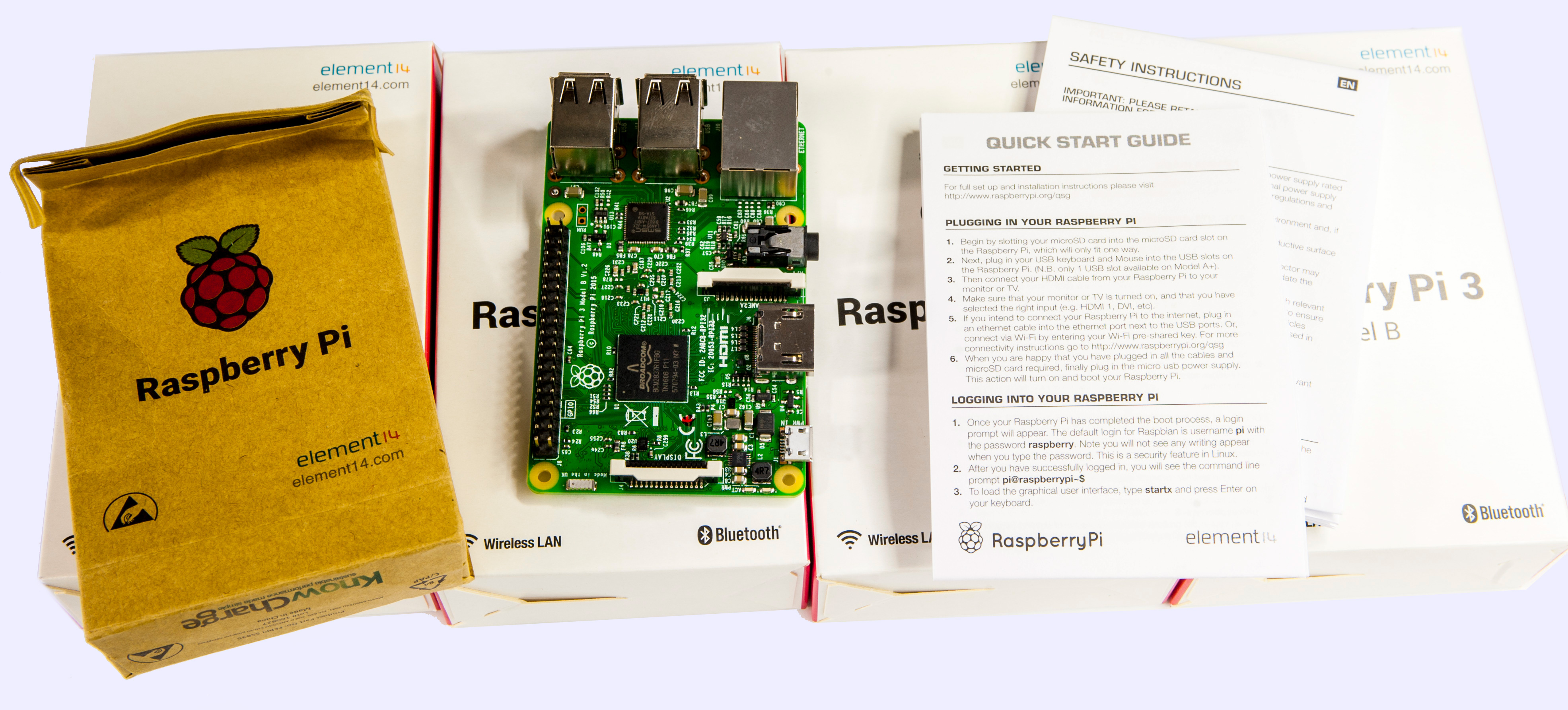
Image 1: Raspberry Pi 3 computer with its retail package
In this article we are not covering interfacing or data processing ability of Raspberry Pi SBC, but rather attempt to squeeze some more performance out it. One of the common ways to get performance gains are increasing running frequency of the processor, memory and storage interface. More frequency – faster computation. That comes at price of increased power consumption and possibly, reducing stability as erroneous operation is more likely under stress. Process of increasing processor speed called overclocking, which is known for few decades already, since the beginning of the digital computing.
Overclocking is not useless as many think, it gives us a glimpse of what can be achieved by better manufacturing process and higher performance parts now, without waiting for the developers and fabs to make actual improved parts. It’s also a measure for reliability, as better overclocking means there is more safety margin available in the design. It’s like destructive impact testing for cars, reveals hardware limits today and let us prepare improvement direction for future products.
Warnings & Disclaimers
All information posted here is hosted just for education purposes and provided AS IS. In no event shall the author, xDevs.com site, or any other 3rd party, including Raspberry Pi foundation be liable for any special, direct, indirect, or consequential damages or any damages whatsoever resulting from loss of use, data or profits, whether in an action of contract, negligence or other action, arising out of or in connection with the use or performance of information published here.
Data provided in this article was verified on actual hardware and software configuration, but there is still room for slight variations in results. Always be honest and responsible of your actions with modifications demonstrated below.
Redistribution and use of this article or any files referenced in it, in source and binary forms, with or without modification, are permitted provided that the following conditions are met:
- Redistribution of article must retain the above copyright notice, this list of conditions, link to this page (https://xdevs.com/article/rpi3_oc/) and the following disclaimer.
- Redistribution of files in binary form must reproduce the above copyright notice, this list of conditions, link to this page (https://xdevs.com/article/rpi3_oc/), and the following disclaimer in the documentation and/or other materials provided with the distribution, for example Readme file.
If you willing to contribute or add your experience regarding your RPi or provide any extra information, such as kernel settings, setup photographs, you can do so following these simple instructions. We also welcome discussion at our own IRC channel.
Raspberry Pi Overclocking methodology
Okay, we want to push some serious speed out of Raspberry Pi 3, where do we start? Great idea would be to study overall system design, what components are present on computer’s PCBA and how we can increase their performance. Take a look on the block diagram below.
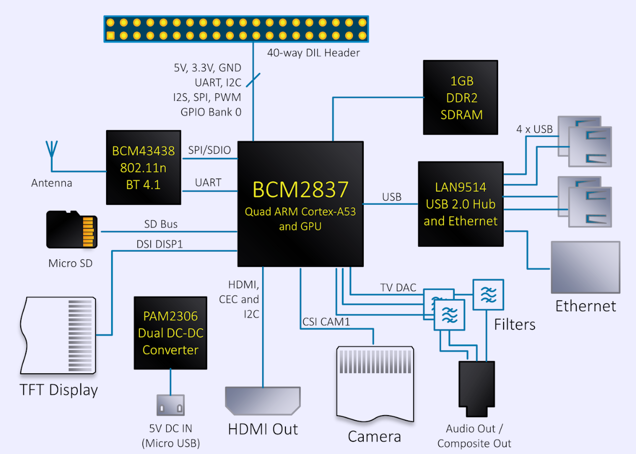
Image 2: Raspberry Pi 3 block diagram with key components
Heart of the Pi is the Broadcom BCM2837 SOC which has quad-core Cortex-A53 ARM processor and VideoCore IV GPU. As these implementations are proprietary to Broadcom, we don’t know exact details, however for purpose of overclocking it’s less important. GPU supports OpenGL ES standard and capable to decode Full-HD 60fps video content in real-time.
Separate 1GB LPDDR2 SDRAM memory chip EDB8132B4PB-8D-F from Elpida (Micron) located on the bottom side. Memory is allocated dynamically between CPU and GPU use, depending on settings from raspi-config tool.
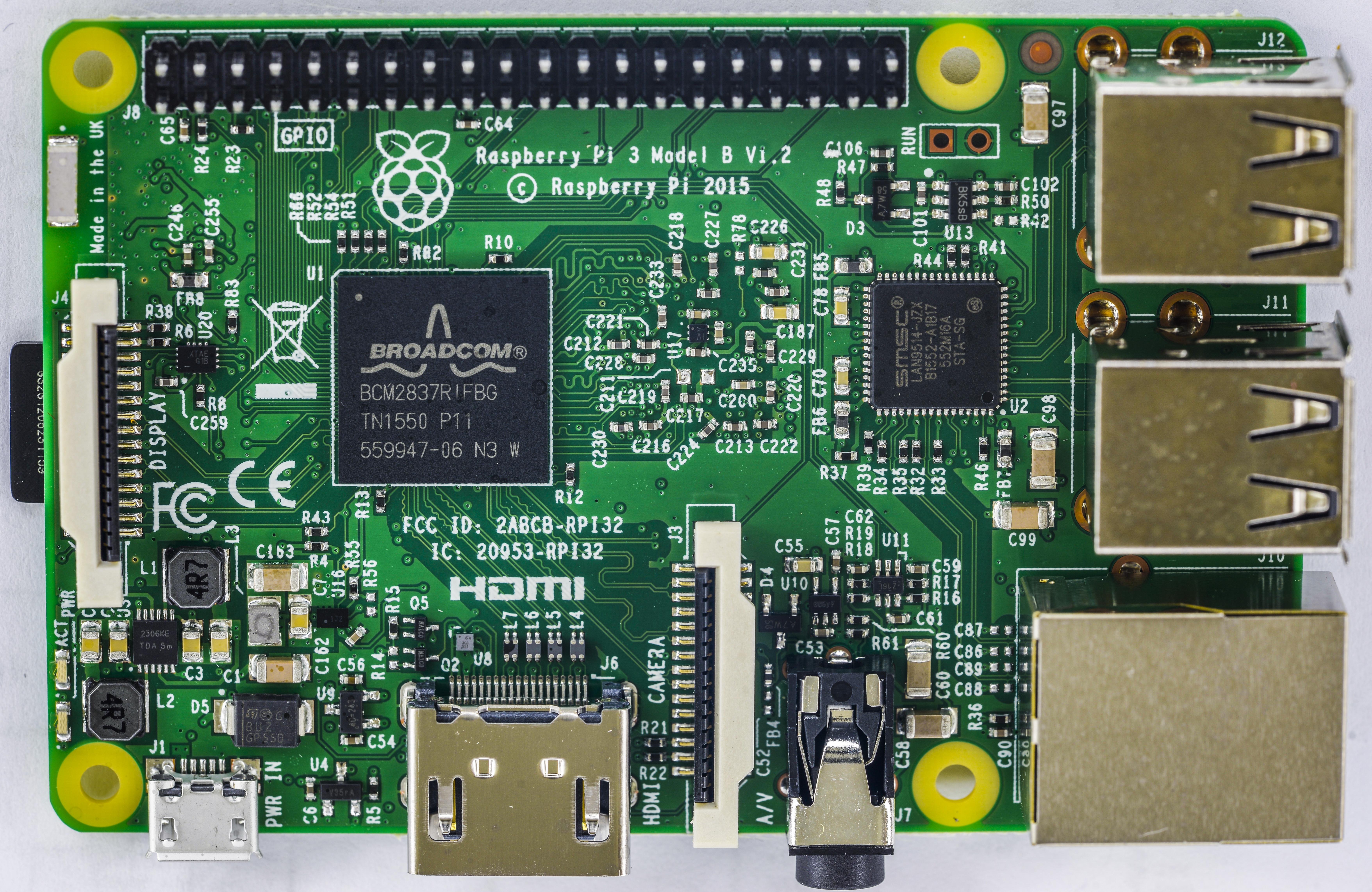
Image 3: Raspberry Pi 3 component side with processor, interface chip and I/O connectors
Connectivity provided by Broadcom BCM43438 WiFi/Bluetooth chip and SMSC LAN9514 USB/LAN Hub. We need to keep these chips alive during overclocking to keep ability of communications with Pi.

Image 4: Raspberry Pi 3 bottom side with LPDDR2 memory chip, WiFi/BT controller and passive components
Bottom side features also micro-SD slot that accepts standard memory cards with Linux OS and lot of various passive components, such as resistors and power decoupling capacitors even in tiny 0201 package. Hopefully we would not need to rework much to reach maximum overclocking speeds.
Now time to check nominal clocks and voltages, for each of the components:
- Nominal max CPU clock is 1200 MHz, with active power management.
- Nominal max GPU 3D-core clock is 300 MHz and 2D-core at 400 MHz.
- LPDDR2 memory clock is 400 MHz (800 MT/s), 2.5ns cycle time.
All clocks are generated internally by PLL section of the SOC, which takes 19.2 MHz input clock from tiny oscillator on the back of the board and multiply that to get higher frequency.
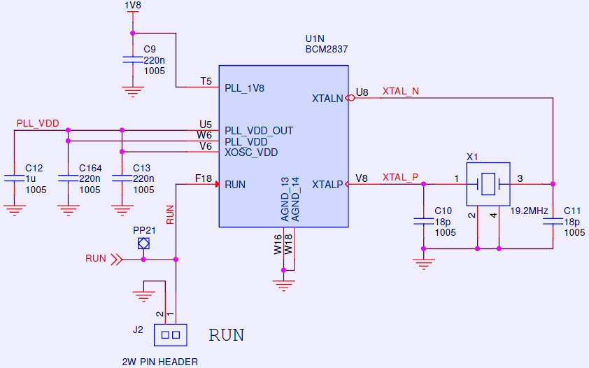
Image 5: Raspberry Pi 3 clock input schematics and PLL power connections
Pi taking all the power from single input – micro-USB connector PWR_IN and have on-board regulators to generate low voltages required by CPU, GPU, LPDDR2 memory and peripherals. It’s important to know the what are these voltages, as higher clocks may require higher voltages to maintain stability and error-free operation. If we know where are these voltages on the board, we can monitor them or even increase by hardware if such requirement appears.
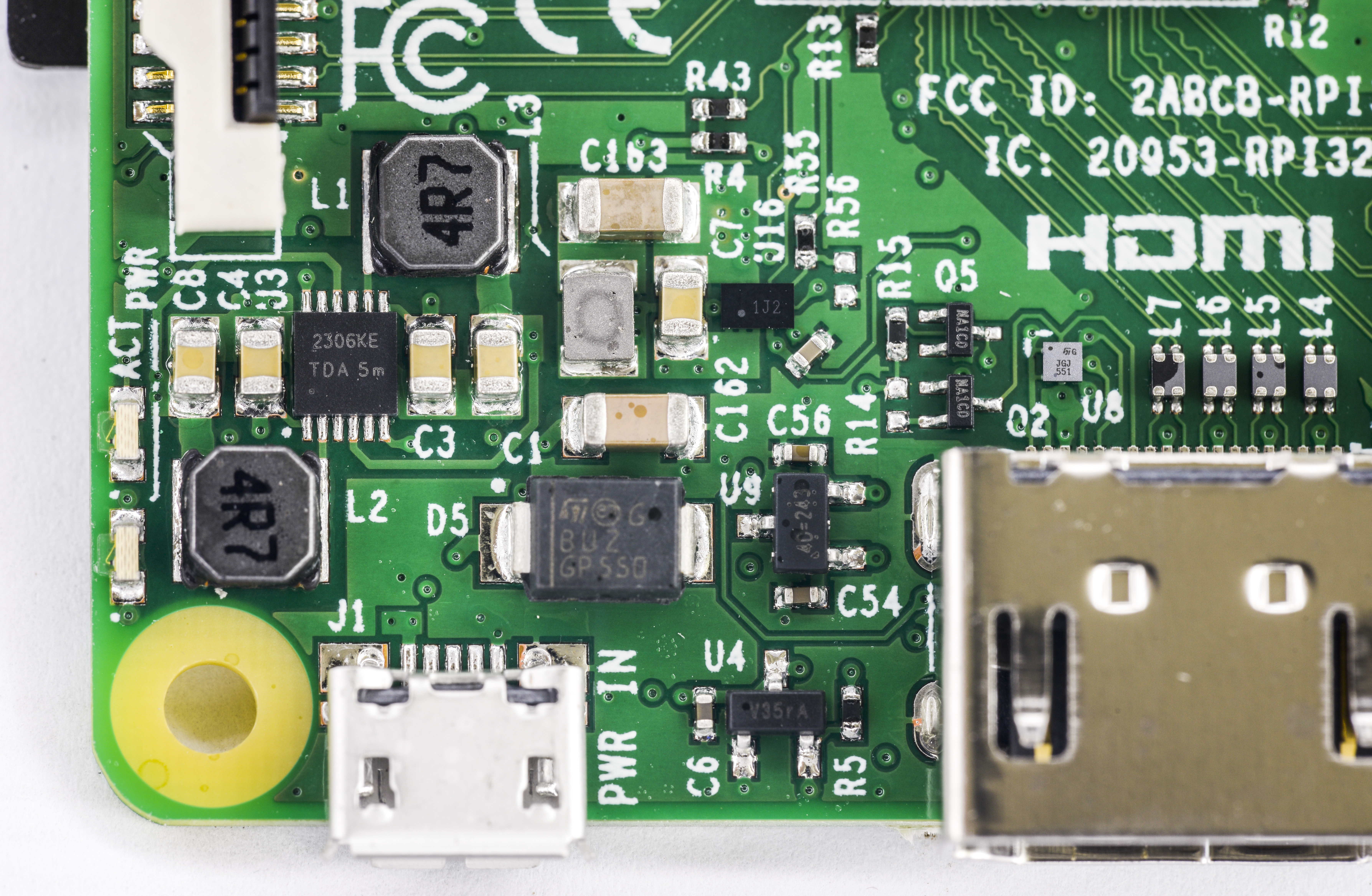
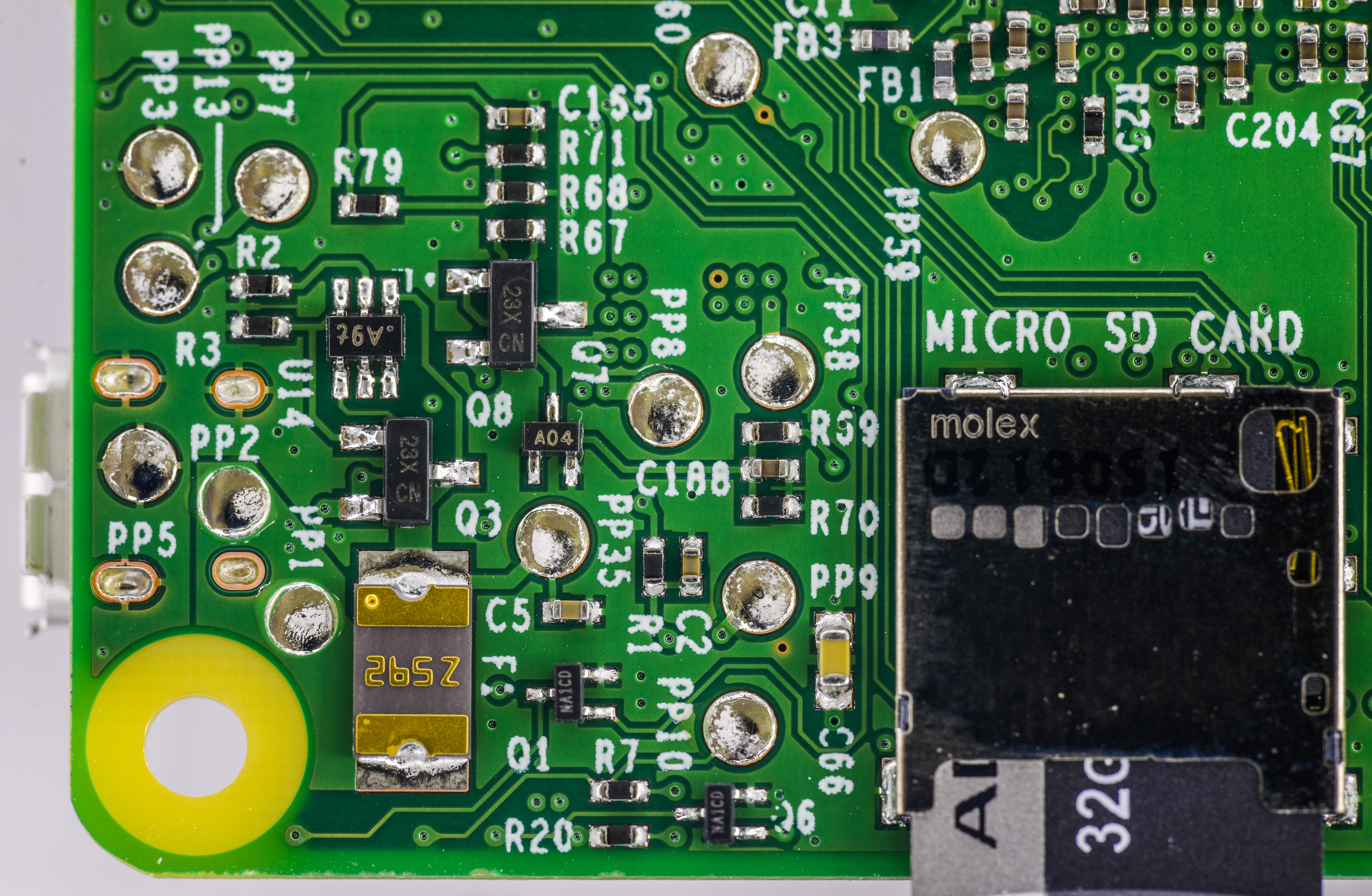
Image 6-7: Close-up on power regulation circuitry on both sides
| Voltage | Source | Usage | Controller | Note |
|---|---|---|---|---|
| +5VDC Input | External PSU | Main power input | Can be alternatively sourced from pin header J8 | |
| +3.3VDC | +5VDC | Main I/O voltage | Diodes PAM2306 | Switching VREG Channel 1 |
| +1.8VDC | +5VDC | DRAM/CPU/GPU voltage | Diodes PAM2306 | Switching VREG Channel 2 |
| PLL, +3.3VDC | SOC LDO | Internal PLL voltage | Internal from BCM2837 | Linear regulator for PLL clock power |
| CPU, +1.0VDC | +5VDC | Main CPU voltage | Richtek RT8088A | Switching VREG |
Table 1: Onboard voltage topology with used controllers spec
Leaned about RPI3 key clocks and voltages, next step would be to boot SBC and install some benchmarks to establish the base line performance, after which we can try to use existing knobs to increase clocks/voltages to compare how much performance difference we gain. It’s important to test actual performance, not just reported MHz speed, since if CPU overheats it could reduce actual running clock to lower values and we get worse performance than expected, often even lower than non-overclocked result. Very same methods apply to “traditional” PC overclocking and benchmarking.
Overclocking is not a magic or voodoo knowledge. Engineers use it all the time during design process, to estimate system reliability margins and limits. It is essential and integral part of every digital system, which have processor, memory and I/O devices. All these building blocks require sync clock signal to receive/send and process all those digital ones and zeroes.
Many of us heard that vendor X or Y have low yield of processors/memory chips. That usually means that large percentage of manufactured silicon dies are not able to meet required design clock. Often that can be tweaked and improved as the production process is tweaked, but sometimes even expensive chip design change is required. Running test clocks during silicon chip manufacturing process are increased to evaluate quality of the chip. If most chips pass design spec tests well, clocks can be increased further to evaluate how much margin process have before transistors stop working reliably. Production of the silicon wafers with billions of transistors is very expensive (think hundreds of M$USD), so often manufacturer sort chips per clock bins and sell slower chips for cheaper SKU while faster ones go for expensive high-end SKUs.
This way more chips can be sold. As time goes, factory process can be improved, and then “slow” SKUs are made just from marketing demand, meaning that overclocking of those can give large gains for free. History knew examples of CPUs that could overclock 50%+ more or even 2 times to their rated frequency. Since test time for silicon fab is very expensive, it can be cheaper to make all chips same “fast” silicon, then specifically manufacture “slow” and “fast” models. Model number and rated speeds are programmed and marked on the finished IC as last step of the manufacturing process.
It also works in opposite direction, to save power and reduce cooling requirements clocks and voltages can be reduced. If you just want to browse web-page or write a text document, you don’t need all those gigahertz clocks and gigabytes/second bandwidths. This is especially important on battery-powered devices, like laptops or phones.
Also running benchmarks for longer time can ensure that there are no errors in operation and device is stable at achieved speeds. There is little help of overclocking if the processor/GPU cannot actually provide correct computation result or crashes half-way the test. Unstable graphics engine can also produce distorted or corrupted images, which can be visible as image artifacts.
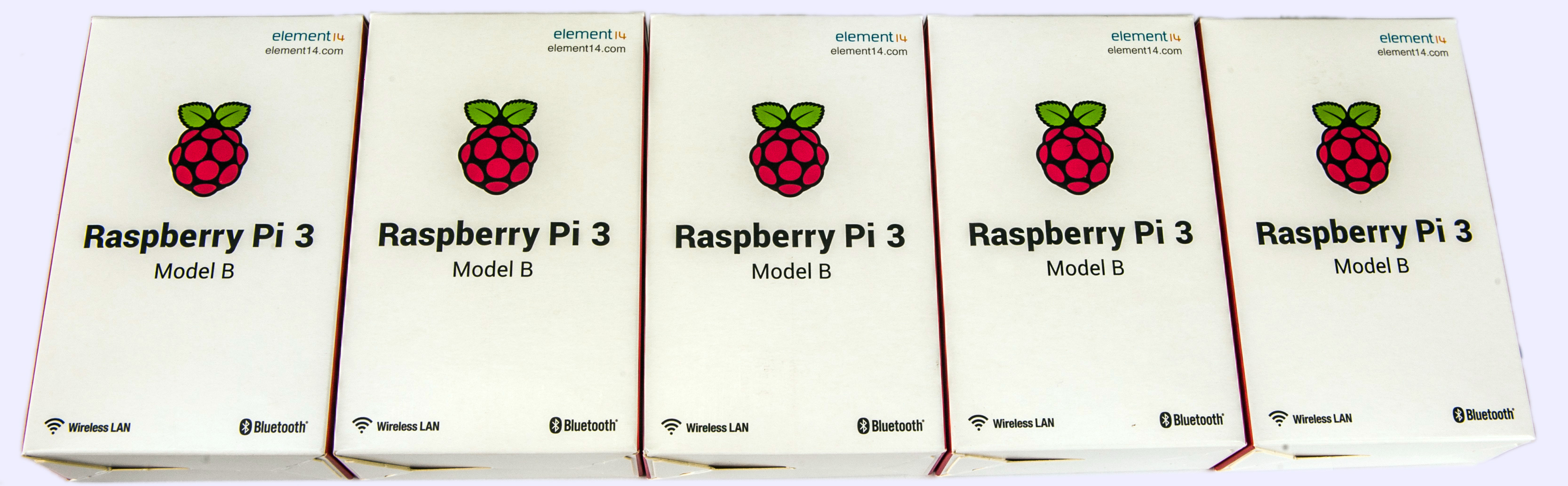
Image 8: Computers received for overclocking experiments
Important note on the actual used sample results. Due to variation in manufacturing process, every piece of silicon, be it processor core or memory have different margin (overclocking ability before data get corrupted). This mean that theoretical chip A may overclock to 1400 MHz, but chip B of the same model and in same condition could reach only 1350 MHz. Chip C on the opposite may be capable to running 1450 MHz. To test this in practice, we get not just one RPI3 module, but five of them to find the best specimen!
Frequency and voltage control settings
To adjust clocks and voltages in traditional computer you have special BIOS Setup interface. Boot settings, low-level device configurations, various memory settings and power management settings are often available in PC BIOS. Little Pi have much smaller room and power in its internal boot-loader, so actual overclocking settings, like clocks are set by special kernel configuration file, located on FAT section of Pi SD card, /boot/config.txt. This file is also accessible without RPi, just by plugging SD card into computer reader, just like standard USB drive.
Table below shows details about each Pi clock and settings range.
| Clock domain | Parameter in /boot/config.txt | Minimum | Default | Maximum |
|---|---|---|---|---|
| CPU/logic clock | arm_freq | 100 | 1200 (for Pi3) | 1600 |
| 2D GPU/L2 cache clock | core_freq | 250 | 400 | 600? |
| Video decoder clock | h264_freq | 300 | ||
| Imaging pipeline clock | isp_freq | 300 | ||
| 3D engine clock | v3d_freq | 300 | ||
| LPDDR2 memory clock | sdram_freq | 200 | 450 | 600? |
Table 2: Available clocks and kernel parameters for adjustment
All these clocks are separate with own clock generation, so they can be adjusted independently. There are also few additional settings that can be tweaked during overclocking endeavors.
- arm_freq_min – Minimum value of arm_freq used in low power state. Default is 600 for Pi3.
- core_freq_min – Minimum value of core_freq used in low power state. Default is 250 for Pi3.
- sdram_freq_min – Minimum value of sdram_freq used in low power state. Default is 400 for Pi3.
- temp_limit – Thermal limit protection threshold. Sets clocks/voltages to default once reached. Default limit is 85 (°C).
- sdram_schmoo=0×02000020 – Memory training tweak. Schmoo name used since shmoo plots are often used for validate semiconductor performance, like memory with variable environment settings.
- over_voltage – Processor logic voltage offset, in 25mV/bit steps. Allowed range from -16 to 8 (8 * 25 = 1.200 VDD_COREDEFAULT + 0.2 = 1.400 V).
- over_voltage_sdram_p – memory cell level voltage offset. Same range math as over_voltage.
- over_voltage_sdram_i – memory I/O voltage offset. Same range math as over_voltage.
- over_voltage_sdram_c – memory logic level voltage offset. Same range math as over_voltage.
- force_turbo – Disable dynamic low power states for RPI SoC. This setting also voids your warranty.
- boot_delay – Some owners reported helpful in case of SD-card data corruption when used with force_turbo.
Overriding temp_limit and force_turbo setting flags void warranty bit on Raspberry Pi 3 computer. Do not try to attempt RMA of overclocked Pi’s.
Now using these knobs, let’s download some benchmarks and run them to see if we can get RPi go fast.
Due to PLL maximum clock range limitation at 3200 MHz on RPi3, there is no known possibility to push real CPU frequency past 1600 MHz. If one to configure higher value, actual real clock that processor running programmed to much lower clock, which is visible by simple performance test:
root@rpi-oc1:/home/pi# java -jar hwbotprime.jar
--------- HWBOT Prime 0.8.3 ----------

Processor detected:
ARMv7 Processor rev 4 (v7l) BCM2835
Estimating speed... 4x 1,650MHz @ -86.187 C
976 MB memory
Running benchmark using 4 threads.
Starting benchmark...
Warm up phase:   .....................................................................................................
Benchmark phase: .....................................................................................................
All done! Current CPU temperature: -84.035 C
Score: 304.56.

Score here should be around 520, if the clock 1650 MHz would be correct, but it's even 44% slower than nominal 1200 MHz clock, about equal to half of desired frequency, 825 MHz CPU clock.
Benchmark software setup
First, download latest Raspbian Stretch official operating system image build. For all testing presented here version from 7 September 2017 with kernel 4.9.41 was used.
# uname -a
Linux rpi-oc1 4.9.41-v7+ #1023 SMP Tue Aug 8 16:00:15 BST 2017 armv7l GNU/Linux
Worth to set CPU power governor in performance mode, to favour less switching from idle state to full-performance state:
echo "performance" |sudo tee /sys/devices/system/cpu/cpu0/cpufreq/scaling_governor
Handy script to measure current CPU frequency and report die temperature:
root@rpi-oc1:/home/pi# cat ./check_cpu_speed_temp.sh
cat /sys/devices/system/cpu/cpu0/cpufreq/scaling_cur_freq
/opt/vc/bin/vcgencmd measure_temp
It is also working good to report negative temperatures (below 0 °C) which is very handy for extreme overclocking.
root@rpi-oc1:/home/pi# ./check_cpu_speed_temp.sh
600000
temp=-35.1'C
First number is running CPU frequency, second temp value is SoC thermal sensor reading. Running frequency drop to 600 MHz when Pi3 is idle to save energy, but will kick to max value once workload is running. Now we ready to install the benchmarks.
HWBOT Prime benchmark
There is OC guide for HWBot Prime benchmark available, which we can try to measure performance in prime numbers calculation. Prime number is a natural number that is greater than 1 and also has no positive divisors other than 1 and itself. For example, 5 is a prime number, but 6 is complex, as it also can be divided by 2 and 3. Large prime numbers are used in many practical applications, such as cryptography, random number generators.
To setup benchmark download the JAR-file:
# wget http://downloads.hwbot.org/hwbotprime.jar
To execute this JAVA-based benchmark we need to preinstall openJDK:http://openjdk.java.net/.
# apt-get install openjdk-8-jre
Starting the benchmark is just simple call for .jar from java environment:
# java -jar hwbotprime.jar
--------- HWBOT Prime 0.8.3 ----------

Processor detected:
ARMv7 Processor rev 4 (v7l) BCM2835
Estimating speed... 4x 1,200MHz @ 61.224 C
970 MB memory
Running benchmark using 4 threads.
Starting benchmark...
Warm up phase:   ..................................................................................................... done!
Benchmark phase: .................................................................................................... done!
All done! Current CPU temperature: 72.522 C
Score: 440.96.
Here’s our example score 440.96. Utility also reports CPU temperature, which can be handy for checks.
OpenJDK library build version have very big impact on the score, so test results can be compared only when using same package versions. You may see many faster results online, using different JDK version.
It’s good idea to run the benchmark multiple times to make sure scores are consistent. Some small variation about few percent is normal.
If the module is unstable, you can get random locks or kernel panic messages, or just bad scores. Few examples presented in logs below:
Message from syslogd@rpi-oc1 at Oct 25 17:41:40 ...
 kernel:[   97.266669] 7fe0: 62442dfc 62442e08 00000000 76f19950 80000010 63208a94 55555d80 55555547
Message from syslogd@rpi-oc1 at Oct 25 17:41:40 ...
 kernel:[   97.296319] Code: 0a00000a f57ff05b e2853028 f593f000 (e1932f9f)
........................................................................................ done!
All done! Current CPU temperature: 9.576 C
Score: 260.77.
Score is two times less than what it’s supposed to be.
root@rpi-oc1:/home/pi# java -jar ./hwbotprime.jar
--------- HWBOT Prime 0.8.3 ----------

Processor detected:
ARMv7 Processor rev 4 (v7l) BCM2835
Estimating speed... 4x 1,500MHz @ 44.007 C
976 MB memory
Running benchmark using 4 threads.
Starting benchmark...
Warm up phase:   .................................................................................................... done!
Benchmark phase: ..................#
# A fatal error has been detected by the Java Runtime Environment:
#
#  Internal Error (os_linux_zero.cpp:254), pid=680, tid=0x624ff470
#  fatal error: caught unhandled signal 11
#
# JRE version: OpenJDK Runtime Environment (8.0_141-b15) (build 1.8.0_141-8u141-b15-1~deb9u1-b15)
# Java VM: OpenJDK Zero VM (25.141-b15 interpreted mode linux-arm )
# Failed to write core dump. Core dumps have been disabled. To enable core dumping, try "ulimit -c unlimited" before starting Java again
#
# An error report file with more information is saved as:
# /home/pi/hs_err_pid680.log
#
# If you would like to submit a bug report, please visit:
#   http://bugreport.java.com/bugreport/crash.jsp
#
Aborted
Here test just crashed due to processor instability.
Sysbench benchmark
Benchmark utility sysbench allow to benchmark processor, memory, file I/O, mutex performance on Linux platforms. It runs in command line interface as console tool.
To install this benchmark on Raspbian OS apt-get tool can be used:
# apt-get install sysbench
Once installation successful, usage is simple execution by single command with desired test parameters. Available parameters for benchmarking:
- —num-threads=N number of threads to use [1]
- —max-requests=N limit for total number of requests [10000]
- —max-time=N limit for total execution time in seconds [0]
- —thread-stack-size=SIZE size of stack per thread [32K]
- —init-rng=[on|off] initialize random number generator [off]
- —test=STRING test to run
Since we have 4 cores, best performance can be achieved with —num-threads=4. Available tests for —test:
- fileio – File I/O test
- cpu – CPU performance test
- memory – Memory functions speed test
- threads – Threads subsystem performance test
- mutex – Mutex performance test
- oltp – OLTP test
Processor test workload, sysbench will verify prime numbers by doing standard division of the number by all numbers between 2 and the square root of the number. CPU benchmark to calculate 20000 prime numbers can be executed like so:
# sysbench --test=cpu --cpu-max-prime=20000 --num-threads=4 run
sysbench 0.4.12:  multi-threaded system evaluation benchmark

Running the test with following options:
Number of threads: 4

Doing CPU performance benchmark

Threads started!
Done.

Maximum prime number checked in CPU test: 20000

Test execution summary:
    total time:                          *110.2904s*
    total number of events:              10000
    total time taken by event execution: 441.0732
Memory test workload benchmark will allocate a memory buffer and then read/write from it. This is then repeated until the provided volume (—memory-total-size) is reached. Users can provide multiple threads (—num-threads), different sizes in buffer (—memory-block-size) and the type of requests (read or write, sequential or random).
# sysbench --test=memory --num-threads=4 --memory-access-mode=rnd --memory-total-size=800M run
sysbench 0.4.12:  multi-threaded system evaluation benchmark

Running the test with following options:
Number of threads: 4

Doing memory operations speed test
Memory block size: 1K

Memory transfer size: 800M

Memory operations type: write
Memory scope type: global
Threads started!
Done.

Operations performed: 819200 (2263497.25 ops/sec)
800.00 MB transferred (2210.45 MB/sec)
For comparison reasons it’s important to keep same settings across the benchmark, so we get apple to apple results.
OpenQuake graphics benchmark
Graphics core in Raspberry Pi is powerful enough to run special version of famous Quake 3! So we can use it to benchmark combined processor and graphics core performance.
wget http://www.berryterminal.com/dl/ioquake3_99.1.36-rpi01_armhf.deb
sudo dpkg -i ./ioquake3_99.1.36-rpi01_armhf.deb
sudo apt-get install openarena
sudo apt-get clean
cp /opt/vc/lib/libbrcmEGL.so /lib/libEGL.so
cp /opt/vc/lib/libbrcmGLESv2.so /lib/libGLESv2.so
Make sure you have set GPU memory size at least 224 MB in raspi-config otherwise game will not start.
To start the benchmark just run /usr/games/openarena
Base-line stock results
| Benchmark test | CPU Frequency | GPU/L2 Frequency | DRAM Frequency | Result | Temperature |
|---|---|---|---|---|---|
| HWBot Prime | Default | Default | Default | 440 | +69.3 |
| Sysbench CPU 20000 | Default | Default | Default | 110.3 sec | +73.6 |
| Sysbench memory 800MB | Default | Default | Default | 2025.5 MB/sec | +49.3 |
Table 3: Baseline benchmark results without overclocking
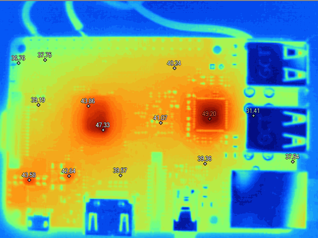

Image 9-10: Thermal images of RPi3 idle, top and bottom sides
Raspberry Pi 3 get rather hot running bare metal, without any heatsinks in still air. Few thermal images taken with Fluke Ti32 camera reveal temperature gradients well. Memory does not get hot at all, barely differ from the board surface temperature. Broadcom SoC runs around +47 °C at idle, and going up to scorching +75 °C under full load.
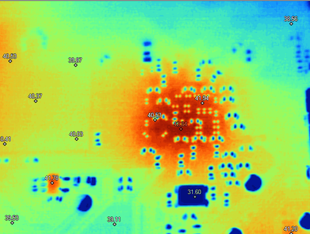
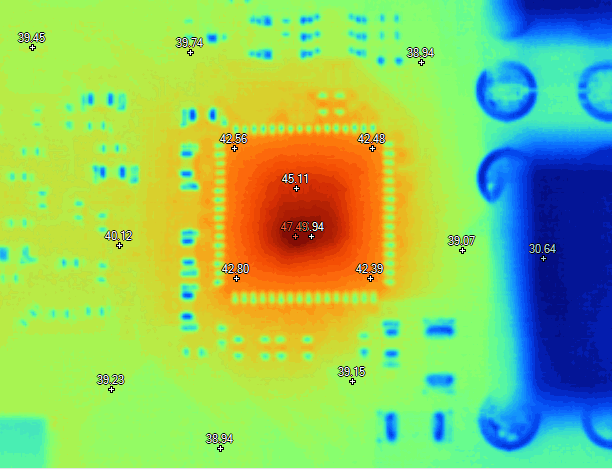
Image 11-12: Thermal images of RPi3 idle, close-up at back side of SoC and USB-LAN hub controller
Based on this images, there is no need to have dedicated heatsinks for memory chip, as it would be cooled from PCB thermal conduction once we get main SoC colder.
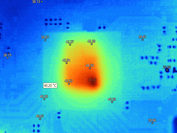
Image 13: Thermal image of Broadcom SoC chip in idle. Can see active core hotspot.
Overclocking results
Initial check was to see what max frequency Pi can boot into console. To perform all CPU and memory speed benchmarks plain headless configuration was used. That means Pi was connected to network over RJ45 port, with sshd running to provide access to console remotely.
To avoid limitations from power supply input, high-end EVGA NEX 1500W PSU was used as power source, which can supply serious 25A on +5V output. Measured voltage was +5.120 V at RPi pins. Connection between Pi and PSU was done using short cable with AWG18 wires.
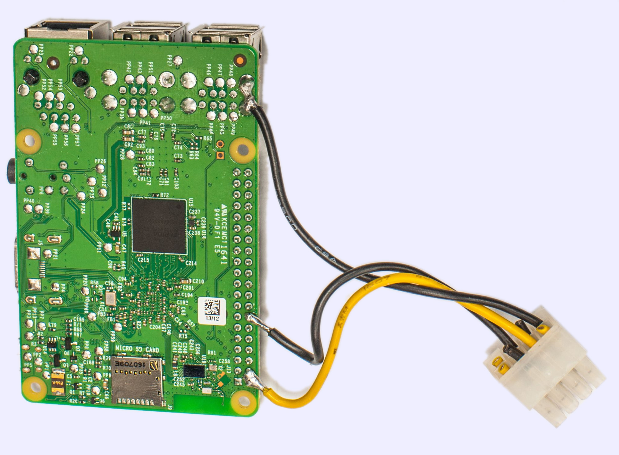
Image 14: Power cable for PSU attached to the Pi
Here are test results per Pi instance:
| Pi sample | Max CPU Frequency | Condition |
|---|---|---|
| 1312 #1 | 1370 MHz, cannot boot 1400MHz | CPU Vcore = 1.4V, memory clock default |
| 3011 #2 | 1470 MHz, cannot boot 1500MHz | CPU Vcore = 1.4V, memory clock default |
| 1911 #3 | 1450 MHz, cannot boot 1500MHz | CPU Vcore = 1.4V, memory clock default |
| 0603 #4 | 1550 MHz, cannot boot 1600MHz | CPU Vcore = 1.4V, memory clock default |
| 1901 #5 | 1500 MHz, cannot boot 1550MHz | CPU Vcore = 1.4V, memory clock default |
Table 4: Board samples and their boot clock ability
Now we know which Pi is the best, and we can take that one for full modification and cooling workout. So all further testing was performed on promising unit #4. Thermal image of Pi overclocked to 1500MHz reveals hot spot at +92 °C! With default throttling settings, that is 7 °C over the throttle limit temperature, when CPU drops speed to reduce stress.

Image 15: Thermal image of RPi3 running HWBOT Prime with overclocking
Improving cooling – air
During typical operation without overclocking Raspberry Pi 3 does not require special heat-sinks or additional cooling. However, with overclocked settings, especially with increased voltage for processor it will get too hot for reliable operation.
Attaching simple aluminum finned heat-sink and additional airflow from fan can provide much better thermal conditions, securing better stability and overclocking headroom. PCB design quite friendly to this simple modifications, as there are no tall components in close proximity to the processor. Thin sticky thermal pad for heat-sink attach will get job done.
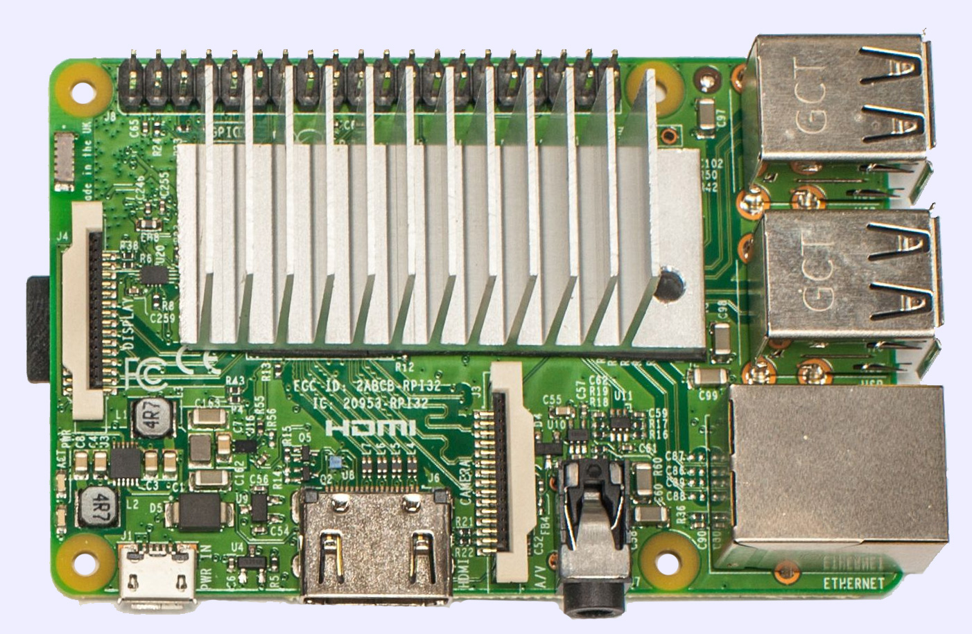
Image 16: Raspberry Pi and massive aluminum heat-sink
With this simple heatsink treatment, Pi was able to run around 1500MHz in loops, stable enough to pass any benchmark benchmarks multiple times.
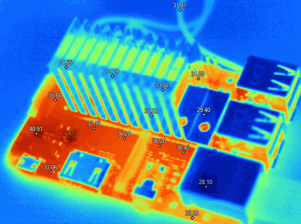
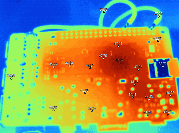
Image 17-18: Thermal image of RPi3 overclocked under load, with additional heatsink
Thermals are now much better, with SoC area reduced to around +57 °C, instead of over +90 °C.
| Benchmark test | CPU Frequency | GPU/L2 Frequency | DRAM Frequency | Result | Temperature |
|---|---|---|---|---|---|
| HWBot Prime | Default | Default | Default | 446 | +51.0 |
| HWBot Prime | 1300 MHz | 450 MHz | 550 MHz | 460 | +53.6 |
| HWBot Prime | 1400 MHz | 450 MHz | 550 MHz | 477 | +54.0 |
| HWBot Prime | 1450 MHz | 450 MHz | 550 MHz | 484 | +50.9 |
| HWBot Prime | 1500 MHz | 450 MHz | 550 MHz | 492 | +52.9 |
| HWBot Prime | 1550 MHz | 450 MHz | 550 MHz | 504 | +51.0 |
| Sysbench CPU 20000 | Default | Default | Default | 92.5 sec | +54.5 |
| Sysbench CPU 20000 | 1400 MHz | 450 MHz | 550 MHz | 79.3 sec | +56.4 |
| Sysbench CPU 20000 | 1500 MHz | 450 MHz | 550 MHz | 73.9 sec | +58.5 |
| Sysbench memory 800MB | Default | Default | Default | 2027.3 MB/sec | +41.3 |
| Sysbench memory 800MB | 1400 MHz | 450 MHz | 550 MHz | 2348.6 MB/sec | +38.6 |
| Sysbench memory 800MB | 1450 MHz | 450 MHz | 550 MHz | 2428.0 MB/sec | +39.1 |
| Sysbench memory 800MB | 1500 MHz | 450 MHz | 550 MHz | 2549.5 MB/sec | +40.0 |
Table 5: Overclocking results using aircooling and additional heatsink with minor airflow
Best score in HWBot Prime benchmark around +15% faster, and memory benchmark yield +26% performance increase. Can it go further?
Voltage modification
To improve stability under extreme operation with 1600 MHz processor clock, VDD_VCORE voltage was supplied externally from EVGA EPOWER V, programmed to 1.500 V. EVGA EPOWER V module can supply up to 2.000 V, which is plenty headroom for needs of this experiment.
This way we are also not limited by over_voltage range 1.400 V maximum limit (setting 8) and can apply arbitrary high voltages.
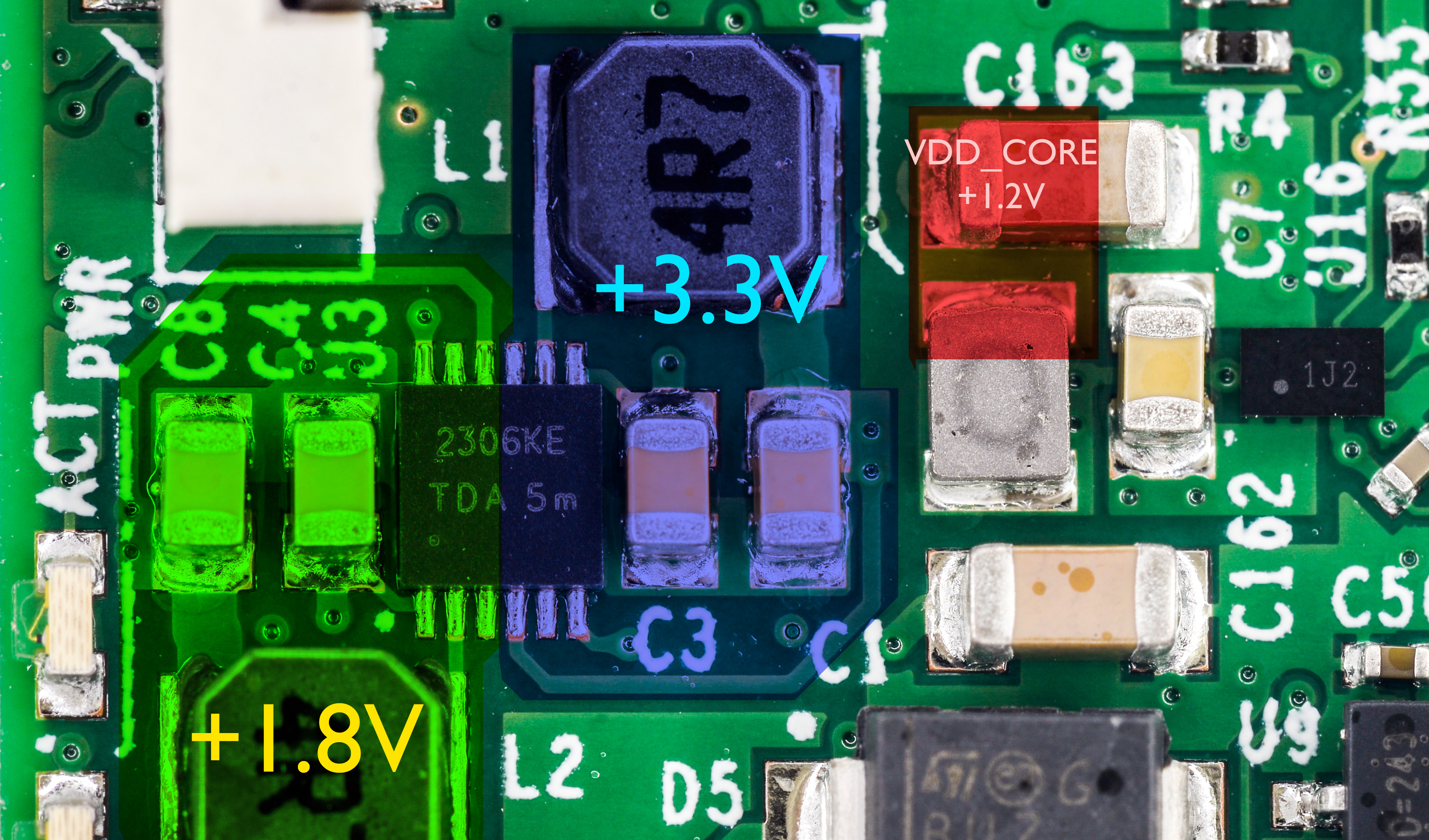
Image 19: Voltage regulator onboard of RPi 3 Model B
To connect external power source, one will need to hook thick enough wire to C163 positive terminal. It’s easy to guess one by looking at connection with little power inductor. This is confirmed by schematic section as well.
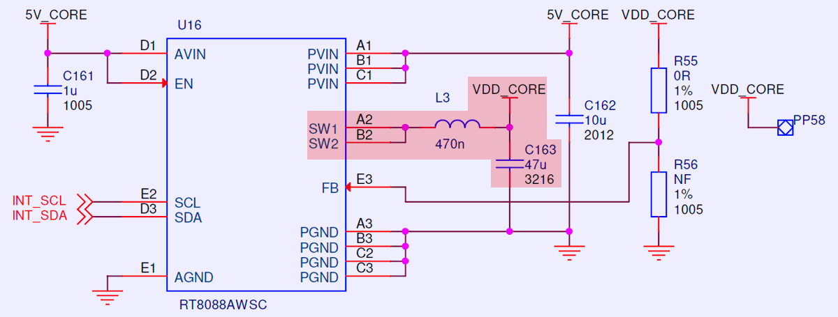
Image 20: Power regulator schematics section
External source connected to this point by AWG18 wire. Since nominal current is barely few amps, just one wire would work well enough. Also return ground wire is important so I’ve used large HDMI connector body to get low-resistance ground connection.
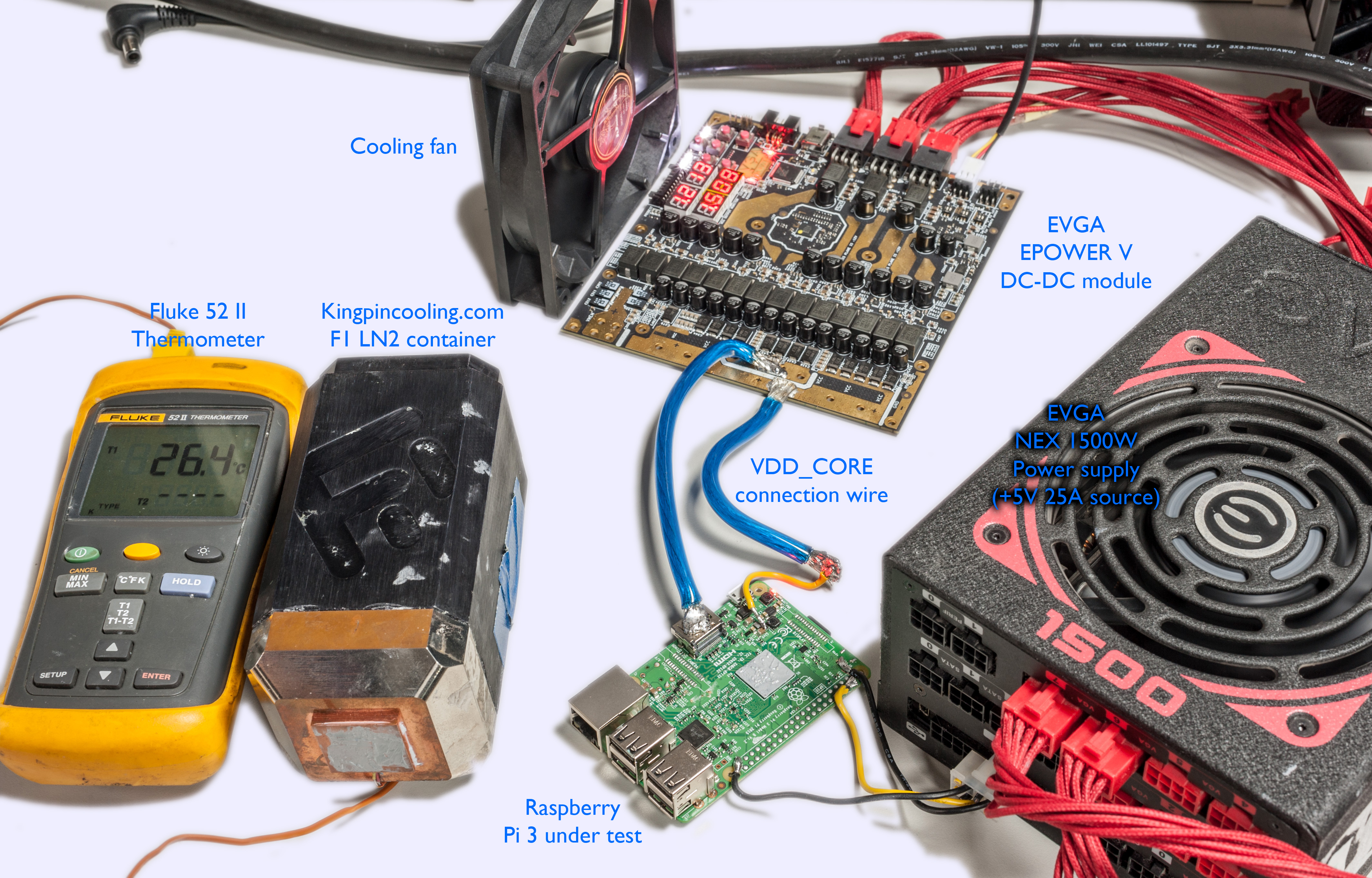
Image 21: Overall overclocking setup with all equipment
Another benefit of using external Core voltage supply is that this voltage not controlled by Pi’s dynamic power management, so we will have constant and stable voltage on the rail, no matter if CPU is idle or busy crunching numbers.
Extreme cooling – liquid nitrogen
Now heatsink was replaced with massive Kingpincooling.com F1 extreme cooling evaporator block. To make it fit Raspberry Pi had some modifications:
- Removed J8 pin header due to interference with the cooling base.
- Removed J3 and J4 FPC and J7 A/V connectors due to interference with the cooling base.
- Both PCBA sides coated with petroleum jelly to avoid water condensate and ice shorting components on the board.
Thermal grease was applied on top of CPU and heavy copper was just standing on top of it. Bottom side was supported by small rubber mat to keep everything flat and steady.
Benefit of using massive copper block for LN2 cooling instead of smaller tube is thermal response time of such system. It will take minutes for small CPU to warm such a large block of cold copper, so as result operation of the whole jig is simple. No need to pour liquid nitrogen all the time to keep stable temperature. Instead just give it a splash to keep temperatures within desired window. Same way extreme overclockers cool traditional PC processors and graphic cards, but at faster rate, as thermal loading of modern multi-core Intel/AMD CPU or NVIDIA/AMD GPU can reach hundreds of watts, unlike little Raspberry Pi 3 SoC. If you interested to see it in action, this video may help to get the idea.

Image 22: LN2 container installed on the Pi’s processor
Since thermal image camera cannot capture temperatures below -30 °C, we will have to use software temperature reporting as a base measure, together with Fluke 52-II thermometer to keep stable container temperature during the benchmark runs.
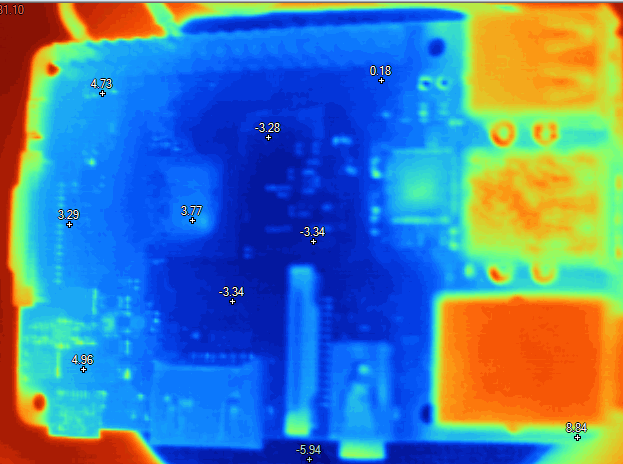
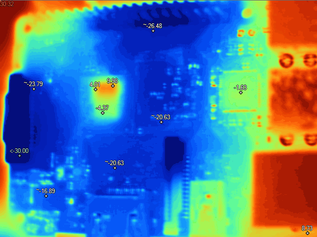
Image 23-24: Thermal image of RPi3 frozen to below zero °C idle and under load
Broadcom SOC chip have cold-bug around -100 °C (by software monitoring value), which means that it will stop working once temperature drops below that. Since LN2 boiling temperature is -196 °C, we need to maintain variable temperature control. This can be done manually, by dozing liquid nitrogen amount supplied to the evaporator block.
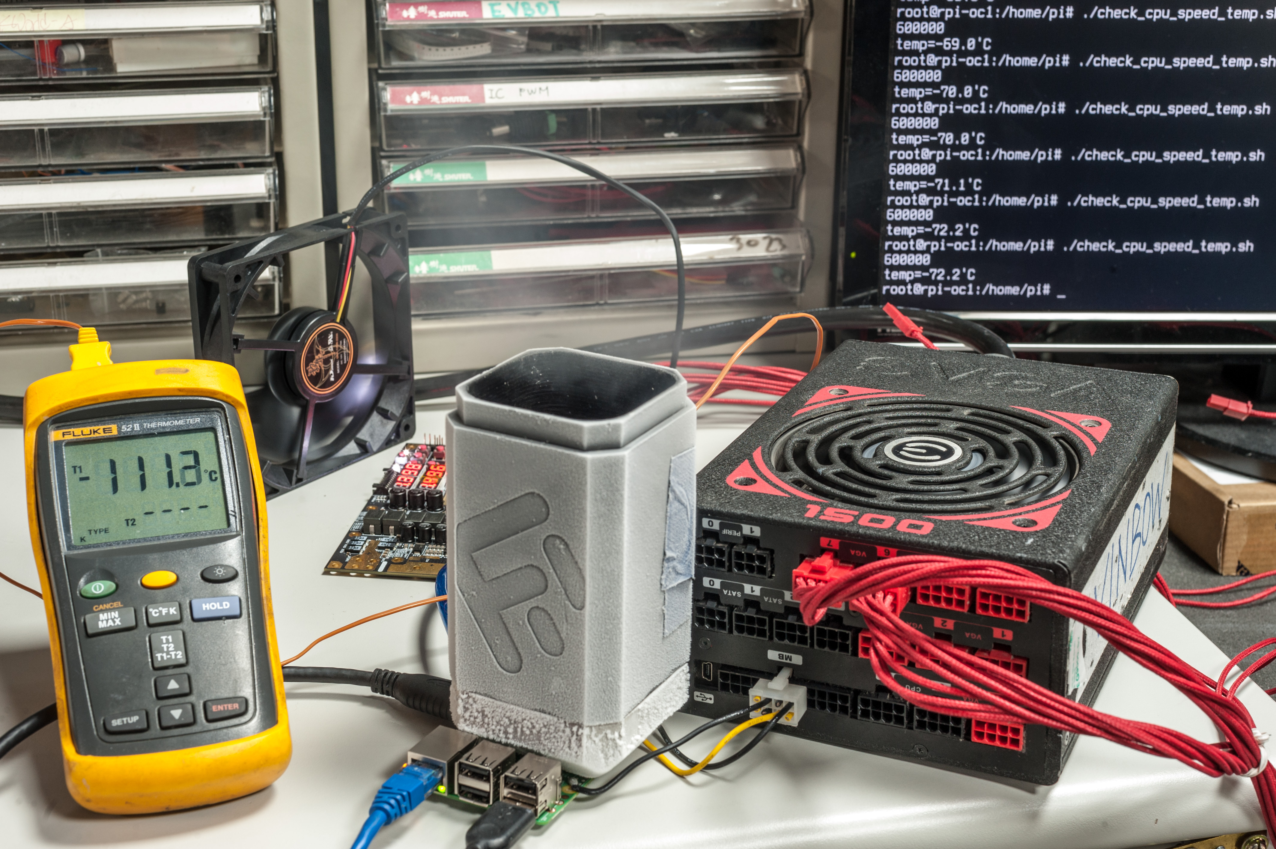
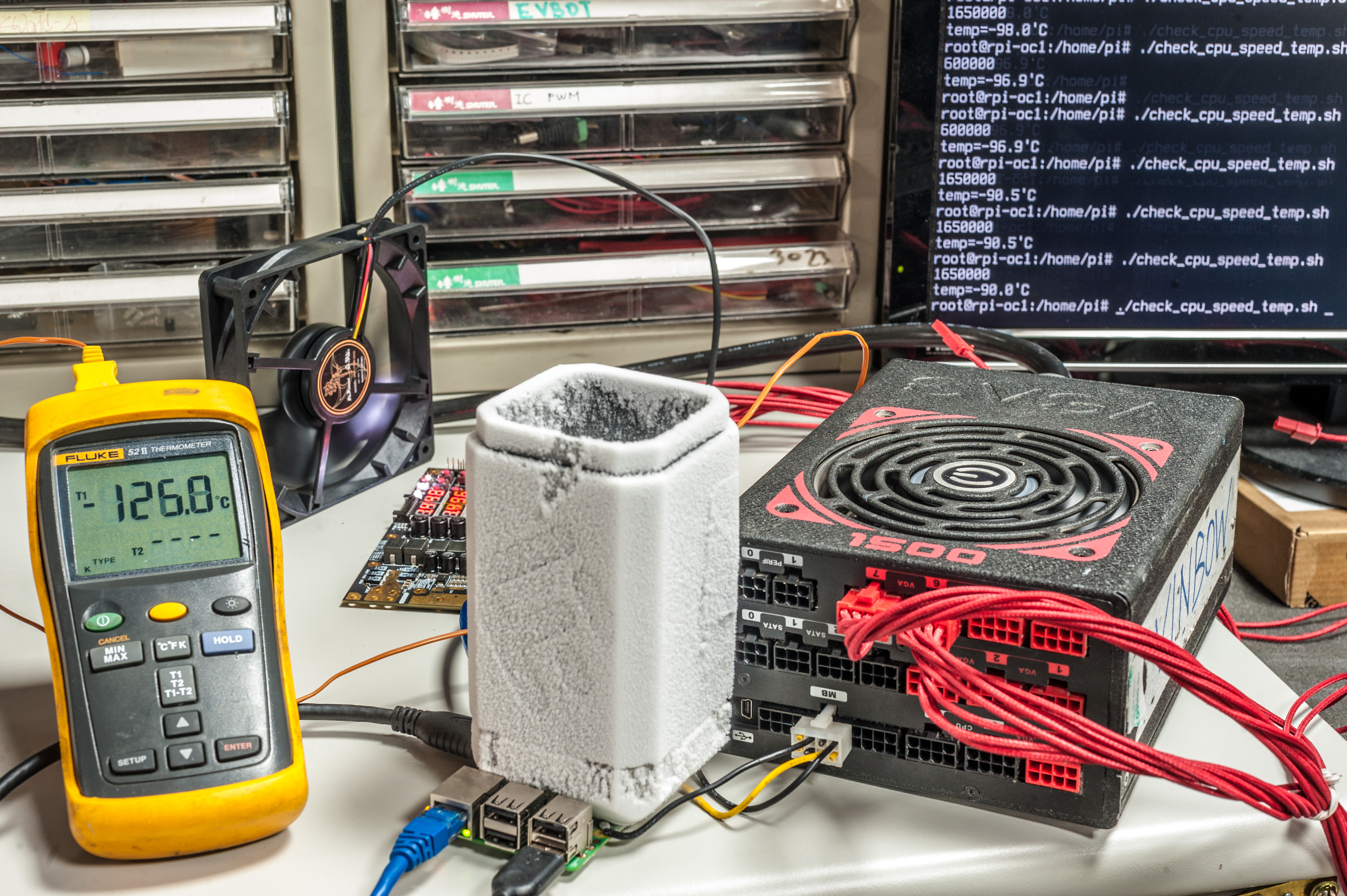
Image 25-26: Graceful cooling procedure to determine possible cold-bug issues
Experimentally it was determined to keep copper block temperature around -120..-140°C to maintain stable Pi temperature close to -80..-90 °C area.
| Benchmark test | CPU Frequency | GPU/L2 Frequency | DRAM Frequency | Result | Temperature |
|---|---|---|---|---|---|
| HWBot Prime | 1550 MHz | 450 MHz | 550 MHz | 504 | -49.0 |
| HWBot Prime | 1600 MHz | 450 MHz | 550 MHz | 512 | -89.9 |
| HWBot Prime | 1600 MHz | 500 MHz | 550 MHz | 514 | -86.8 |
| Sysbench CPU 20000 | 1550 MHz | 450 MHz | 550 MHz | 71.5 sec | -25.2 |
| Sysbench CPU 20000 | 1600 MHz | 450 MHz | 550 MHz | 69.3 sec | -77.4 |
| Sysbench memory 800MB | 1550 MHz | 450 MHz | 550 MHz | 2582.1 MB/sec | -21.0 |
| Sysbench memory 800MB | 1600 MHz | 500 MHz | 600 MHz | 2772.7 MB/sec | -86.3 |
Table 6: Extreme overclocking results with maxed out CPU frequency.
Getting 1550 MHz stable did not require very cold temperatures, chip was functioning fine even with just -20 °C. 1600 MHz was stable once temperatures are below -45…-50 °C.
Quake 3D game demo was also running flawless on maximum CPU frequency, however due to software configurations there was no benchmark data to compare with.
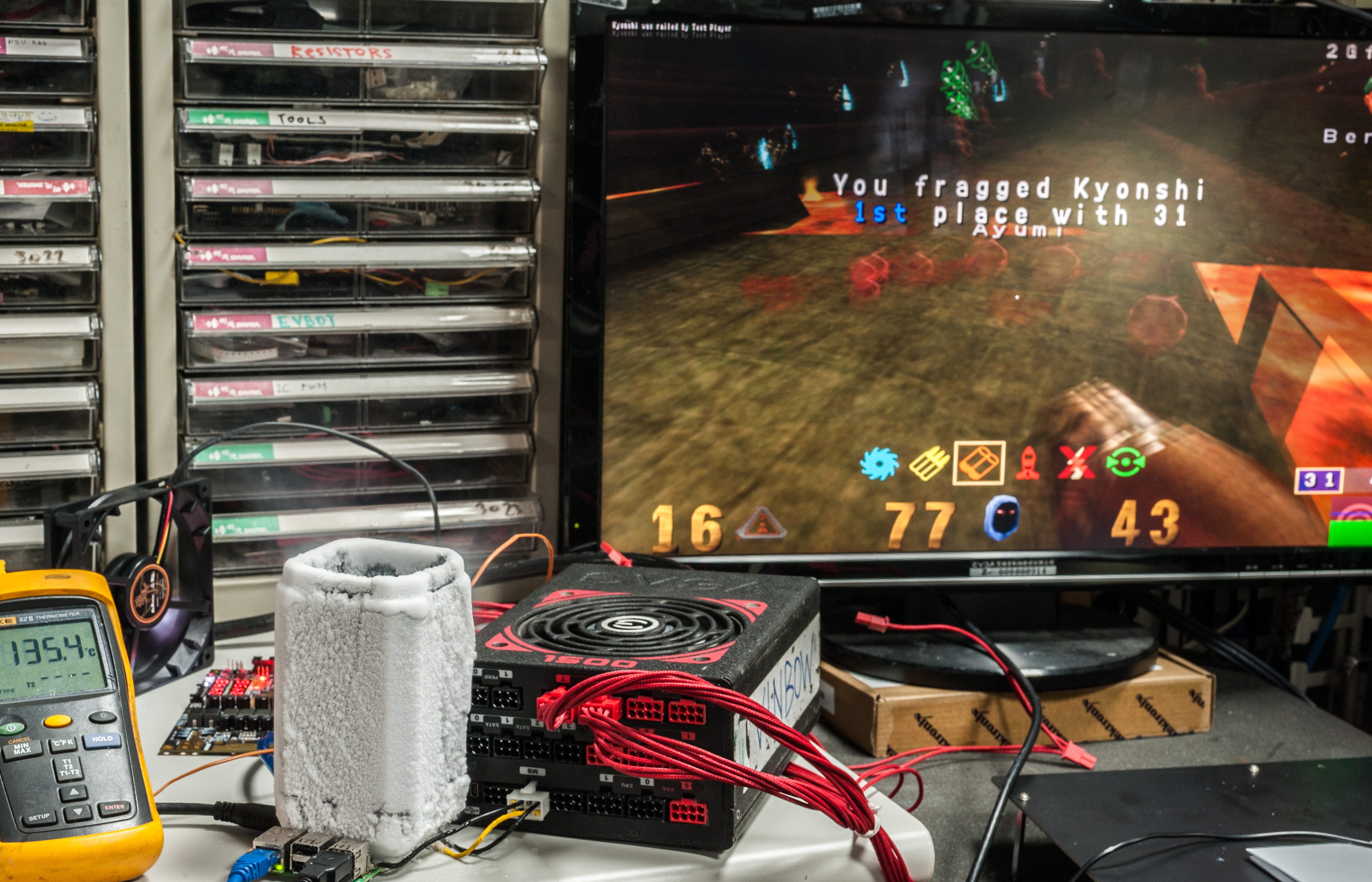
Image 27: Running OpenQuake 3 on Raspberry Pi 3 cooled at -90 °C
Fastest run logs presented below.
HWBOT Prime test
This test completed without issues at maximum 1600 MHz clock.
root@rpi-oc1:/home/pi# java -jar ./hwbotprime.jar
--------- HWBOT Prime 0.8.3 ----------

Processor detected:
ARMv7 Processor rev 4 (v7l) BCM2835
Estimating speed... 4x 1,600MHz @ -88.34 C
976 MB memory
Running benchmark using 4 threads.
Starting benchmark...
Warm up phase:   ..................................................................................................... done!
Benchmark phase: ..................................................................................................... done!
All done! Current CPU temperature: -82.959 C
Score: 514.53.
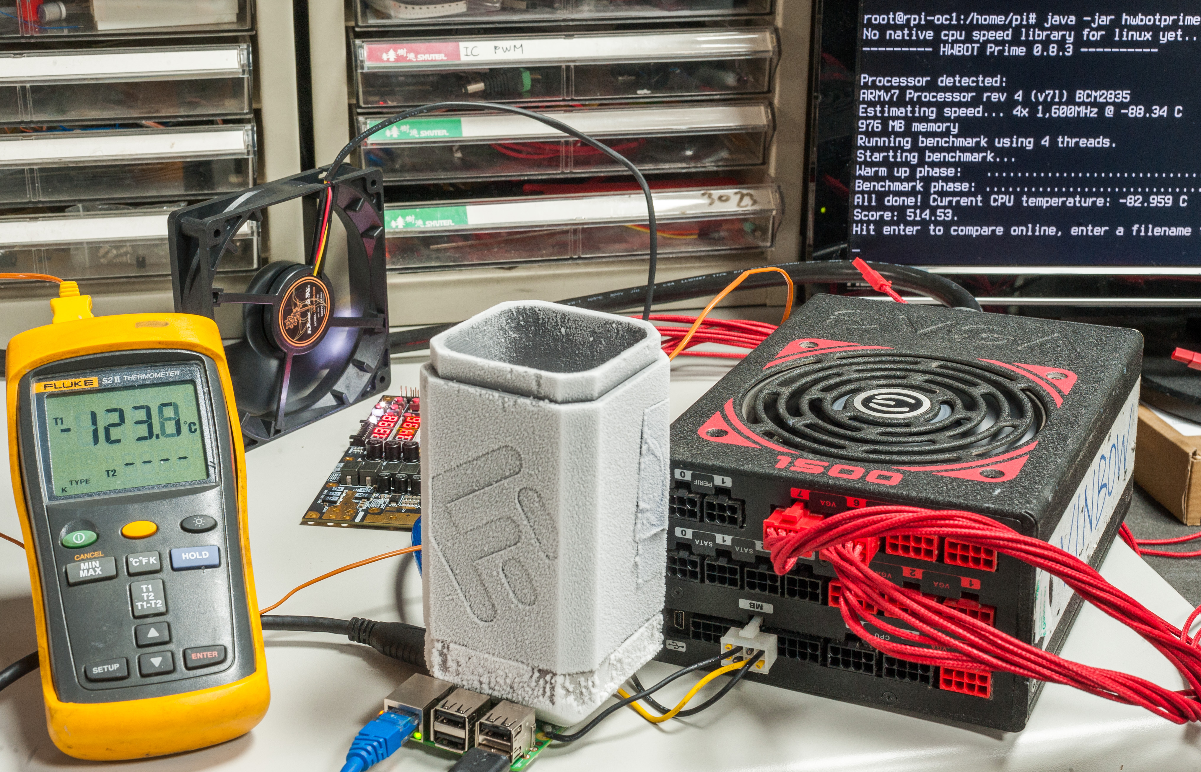
Image 28: Running HWBOT Prime on Raspberry Pi 3 cooled at -90 °C
CPU Prime test
Same CPU clock = 1600MHz.
root@rpi-oc1:/home/pi# sysbench --test=cpu --cpu-max-prime=20000 --num-threads=4 run
sysbench 0.4.12:  multi-threaded system evaluation benchmark

Running the test with following options:
Number of threads: 4

Doing CPU performance benchmark

Threads started!
Done.

Maximum prime number checked in CPU test: 20000


Test execution summary:
    total time:                          69.3621s
    total number of events:              10000
    total time taken by event execution: 277.3169
    per-request statistics:
         min:                                 27.66ms
         avg:                                 27.73ms
         max:                                 67.71ms
         approx.  95 percentile:              27.76ms

Threads fairness:
    events (avg/stddev):           2500.0000/3.00
    execution time (avg/stddev):   69.3292/0.01
Memory test
root@rpi-oc1:/home/pi# sysbench --test=memory --num-threads=4 --memory-access-mode=rnd --memory-total-size=800M run
sysbench 0.4.12:  multi-threaded system evaluation benchmark

Running the test with following options:
Number of threads: 4

Doing memory operations speed test
Memory block size: 1K

Memory transfer size: 800M

Memory operations type: write
Memory scope type: global
Threads started!
Done.

Operations performed: 819200 (2839246.15 ops/sec)

800.00 MB transferred (2772.70 MB/sec)
Are these numbers worth the nitrogen used? Not really, but it was fun to see how can it run and what limitations are in ARM-based computer overclocking. If CPU clock frequency could be increased higher than 1600 MHz, we would likely to see much bigger impact from going to extreme overclocking.
But until then, that’s all for now.
Summary and conclusion
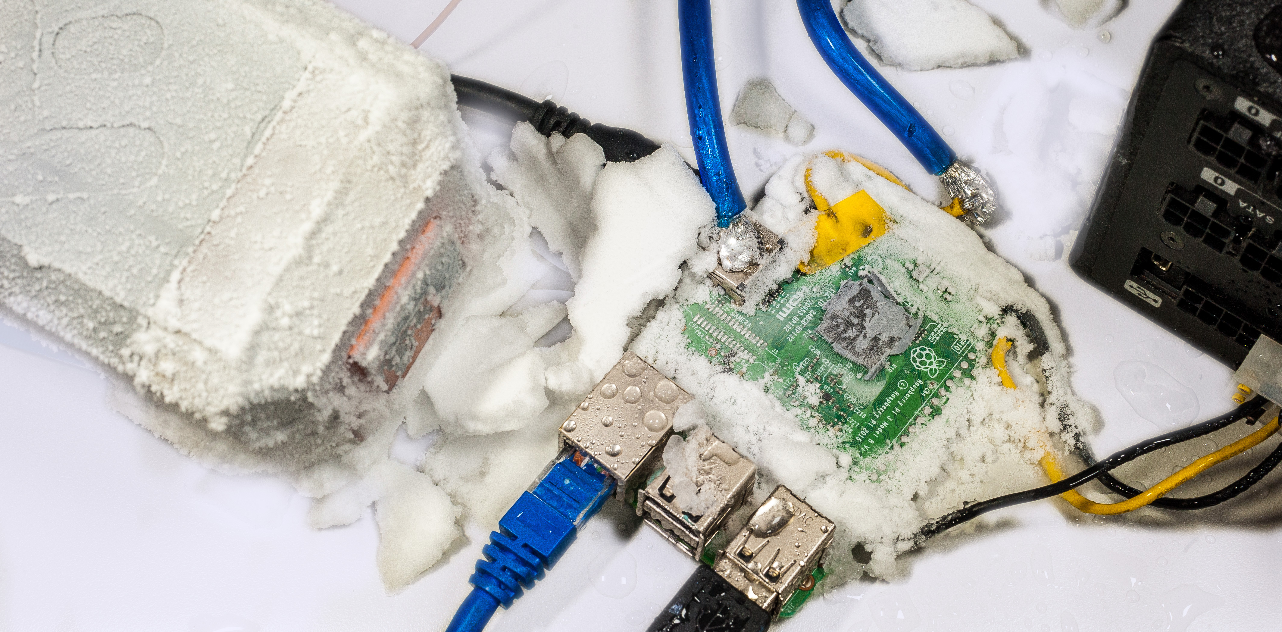
Image 29: Frozen Raspberry Pi 3 in snow after extreme OC session.
Overclocking is fun as hobby, but it can also be useful in practical applications. Jack Zimmermann show excellent example how overclocking Raspberry Pi 3 in role of Stratum-1 NTP time server help to reduce uncertainty of GPS time syncronization.
Another possible use for overclocked Raspberry Pi is various cross-platform emulators and game console emulators, where performance is never enough. Scientific applications with heavy math may also enjoy few seconds of computation time shaved, however you need to be sure data is not very important, as chance to get errors in results with faster clocks are only increasing.
With little help of liquid nitrogen, we managed to overclock Raspberry Pi 3 Model B to its maximum 1600 MHz limit without much trouble. This article reveals few basic bits about overclocking theory and methods. It’s not a rocket science, so anyone can do it, and getting cryogenic liquids is not mandatory. In the end, it’s another way to have some fun with this little capable microcomputer. Feel free to share and link to this page, but keep links and all references intact, as this guide may be updated in future.
If there are any questions remain open, you can also join our IRC chat to discuss.
Projects like this are born from passion and a desire to share how things work. Education is the foundation of a healthy society - especially important in today's volatile world. xDevs began as a personal project notepad in Kherson, Ukraine back in 2008 and has grown with support of passionate readers just like you. There are no (and never will be) any ads, sponsors or shareholders behind xDevs.com, just a commitment to inspire and help learning. If you are in a position to help others like us, please consider supporting xDevs.com’s home-country Ukraine in its defense of freedom to speak, freedom to live in peace and freedom to choose their way. You can use official site to support Ukraine – United24 or Help99. Every cent counts.
Modified: Jan. 5, 2023, 1:01 a.m.
References
- Raspberry Pi 3B Product page
- Raspbian OS download page
- Raspberry Pi : Overclocking parameters
- Retroresolution.com : Raspberry Pi 3 – Stable and Unstable Overclock Values
- Jackenhack : Raspberry Pi 3 Overclocking and NTP benchmarks
- Jeremy Morgan : How to Overclock Your Raspberry Pi
- Kingpincooling.com Forum : RRainbo's RaspberryPi OC Adventure
- This article in printable PDF-format
- HackSpace : Ultimate Overclocking RPi3