Contents
- Intro
- Disclaimer
- Manual references
- Parts donor meter teardown
- Teardown and repair
- Firmware versions
- Calibration and accuracy verification
- Summary
Intro
One of the readers contacted us to assist with repair of old Fluke DMM, and as we currently doing some work on 8846A/8508A meters, adding old Fluke also felt right, even just for sake of complete coverage.
In this short article benchtop multimeter from Fluke, Model 8842A will be repaired, calibrated and tested. This is old but still nice and easy to use lab workhorse. It may not have fancy touchscreen TFT display, or Linux-based OS with megabytes of storage, but it is fast, powers on instantly and holds the accuracy well. All measurement functions are provided in 5½-digit or fast 4½-digit resolution.
There is also lower grade Fluke 8840A, which does not have 20mV/20Ω ranges, have bit worse accuracy, but otherwise based on same design with fewer selected parts.
Fluke 8842A’s key feature highlights:
- 5½ digit resolution for all key functions, maximum input voltage 1000VDC/700VAC.
- Best DCV absolute accuracy 25 ppm for 2V and 20V ranges
- Large digit vacuum display with excellent viewing angles and contrast
- A/D internal linearity 2 ppm of measurement + 1 ppm of range
- 200 mA to 2 A current range (also protected with internal HRC fuse)
- 2-wire and 4-wire resistance ranges from 20 Ω to 20 MΩ
- Optional GPIB interface with external triggering for remote connection/control
Best accuracy specifications on main functions:
| Measurement Function | Range | Best accuracy, 90 day, within ±1 °C TCAL |
|---|---|---|
| DC Voltage | ±19.9999 mV to 1000 V | ±25 ppm of reading + 2 ppm on the 2V range, High-impedance mode for 20mV-20V ranges |
| DC Current | ±200 mA and ±2 A | ±400+ ppm for 200mA |
| AC Voltage True RMS | 200 mV to 700 V, 20 Hz to 100 kHz | ±700+ ppm for 2V-200V |
| AC Current | 200 mA and 2 A, 20 Hz to 5 kHz | ±1000+ ppm |
| Resistance 4W/2W | 20 Ω – 20 MΩ | ±50+ ppm on 2 kΩ and 20 kΩ ranges |
Table 1: 8842A function list best accuracy for 90 days
Front panel is simple and easy to use. Front/rear and power buttons are fully mechanical, no stand-by or soft-buttons like in modern gear. OFFSET button operate like NULL, taking current reading as a reference and subtracts it from all further measurements, until deactivated by second keypress. Calibration mode switch is accessible thru small hole on bottom right side of the screen lens.

Image 1: Front panel of 8842A 5½-digit DMM.
Exterior visual inspection revealed no damages. Rear side feature just power input block, mains voltage selector and rear inputs for voltage/resistance functions. Current input accepted only at the front inputs.
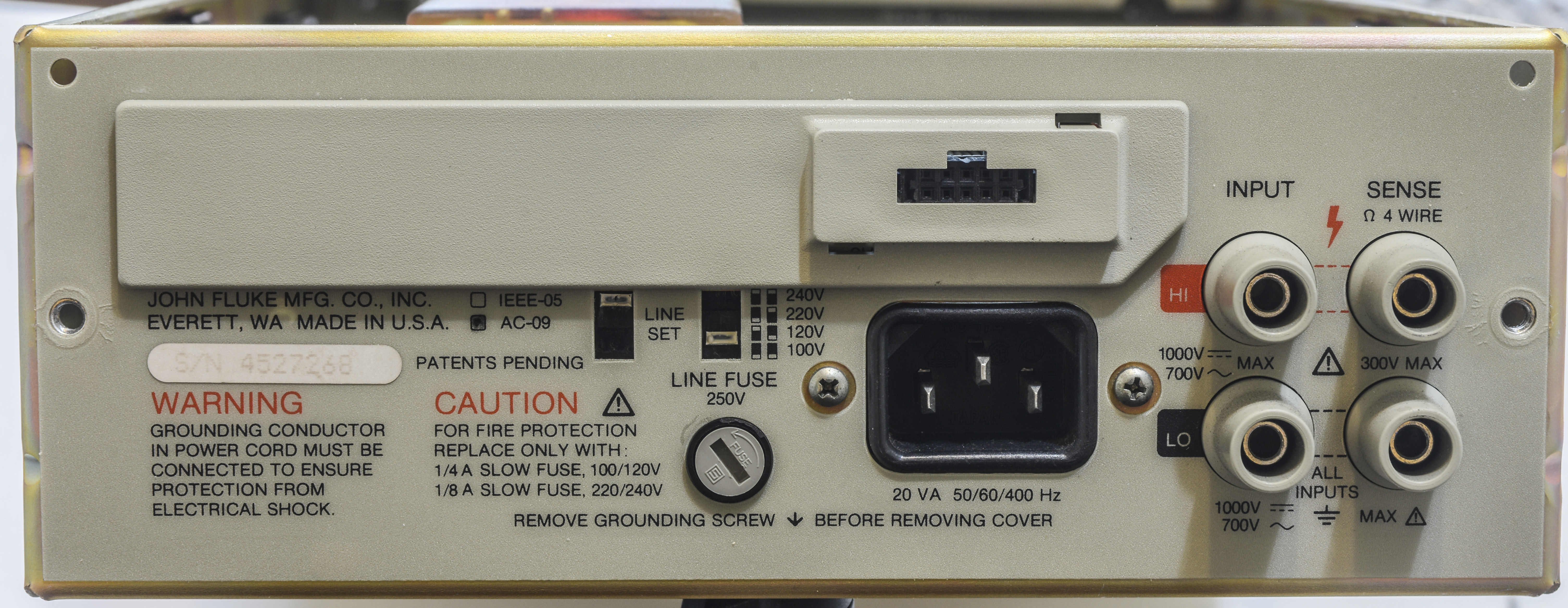
Image 2: 8842A rear side. GPIB interface card would be present in place of plastic cover
There are also few options for this meter. Sadly, base meter configuration does not have any remote interface.
| Option P/N | Description |
|---|---|
| 8842A-09 | ACV and ACI functions module |
| 8842A-05 | Remote IEEE-488 GPIB interface module |
Table 2: 8842A options
But we have TrueRMS ACV/ACI module, so that operation of that option will be tested.
Disclaimer
Redistribution and use of this article, any part of it or/and any images or files referenced in it, in source and binary forms, with or without modification, are permitted provided that the following conditions are met:
- Redistributions of article must retain the above copyright notice, this list of conditions, link to this page (/fix/f8842a) and the following disclaimer.
- Redistributions of files in binary form must reproduce the above copyright notice, this list of conditions, link to this page (/fix/f8842a), and the following disclaimer in the documentation and/or other materials provided with the distribution, for example Readme file.
All information posted here is hosted just for education purposes and provided AS IS. In no event shall the author, xDevs.com site, or any other 3rd party, including Fluke/Tektronix be liable for any special, direct, indirect, or consequential damages or any damages whatsoever resulting from loss of use, data or profits, whether in an action of contract, negligence or other tortuous action, arising out of or in connection with the use or performance of information published here.
If you willing to contribute or add your experience regarding instruments repairs or provide extra information, you can do so following these simple instructions
Manuals and documentation
8842A Instruction manual with schematics
8840A Instruction manual with schematics
Manuals have very good coverage on service information, fully featured schematics and BOM lists, and well explained theory of operation. It’s a joy to use old instruments manuals like this, made to much higher standards than accepted today.
Parts donor meter teardown
xDevs.com team got another 8842A meter with broken VFD glass for donor interesting parts for another metrology project. There are some nice projects out there with LED replacement displays, such as this one but I didn’t think it is worth the time for me to spend time restoring donor instrument.
Let’s take donor meter apart first:
There is no GPIB remote interface option on either meters, so while this unit might be fixable, there is no easy way to readout/display readings on unit with broken display.
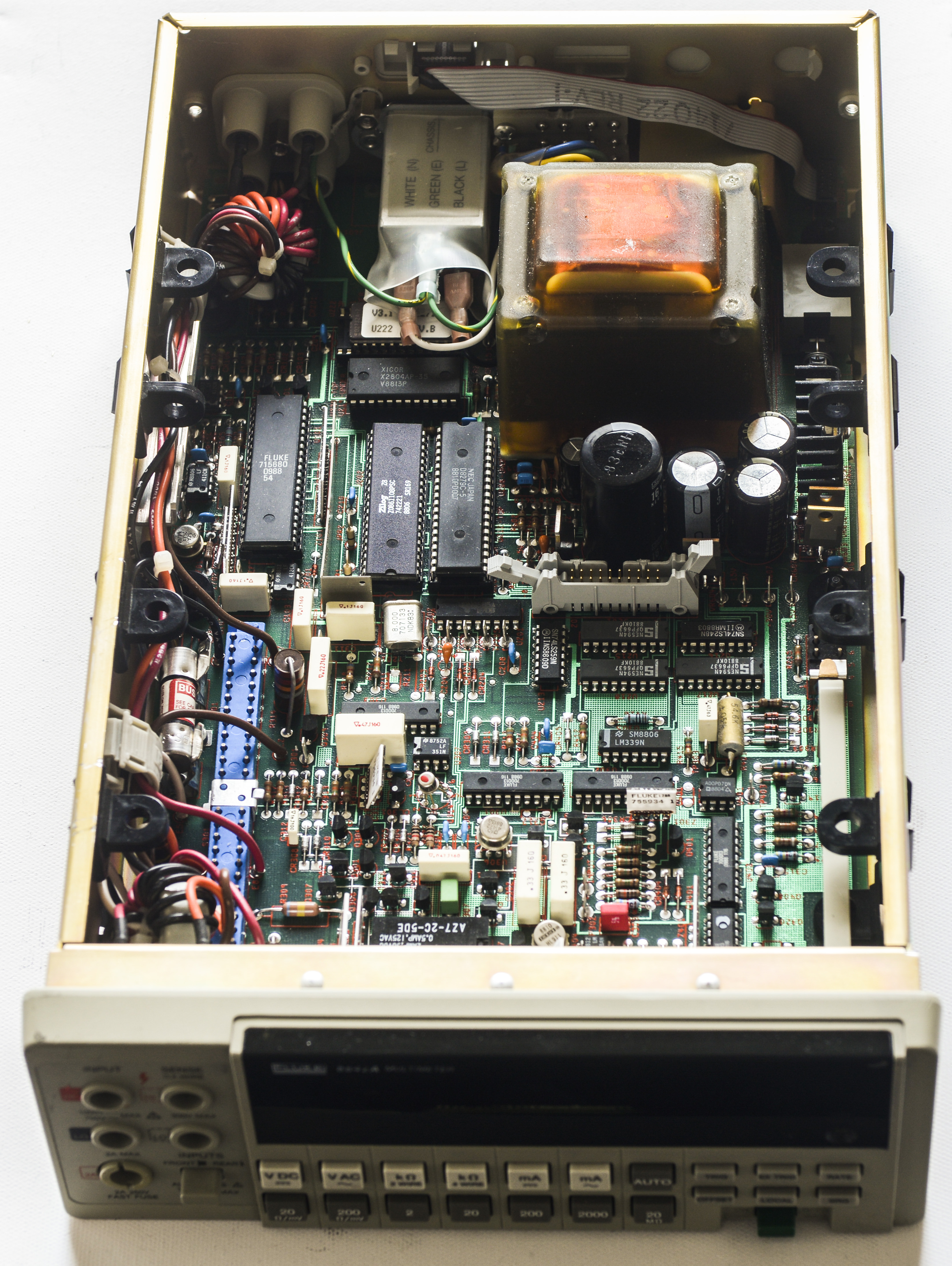
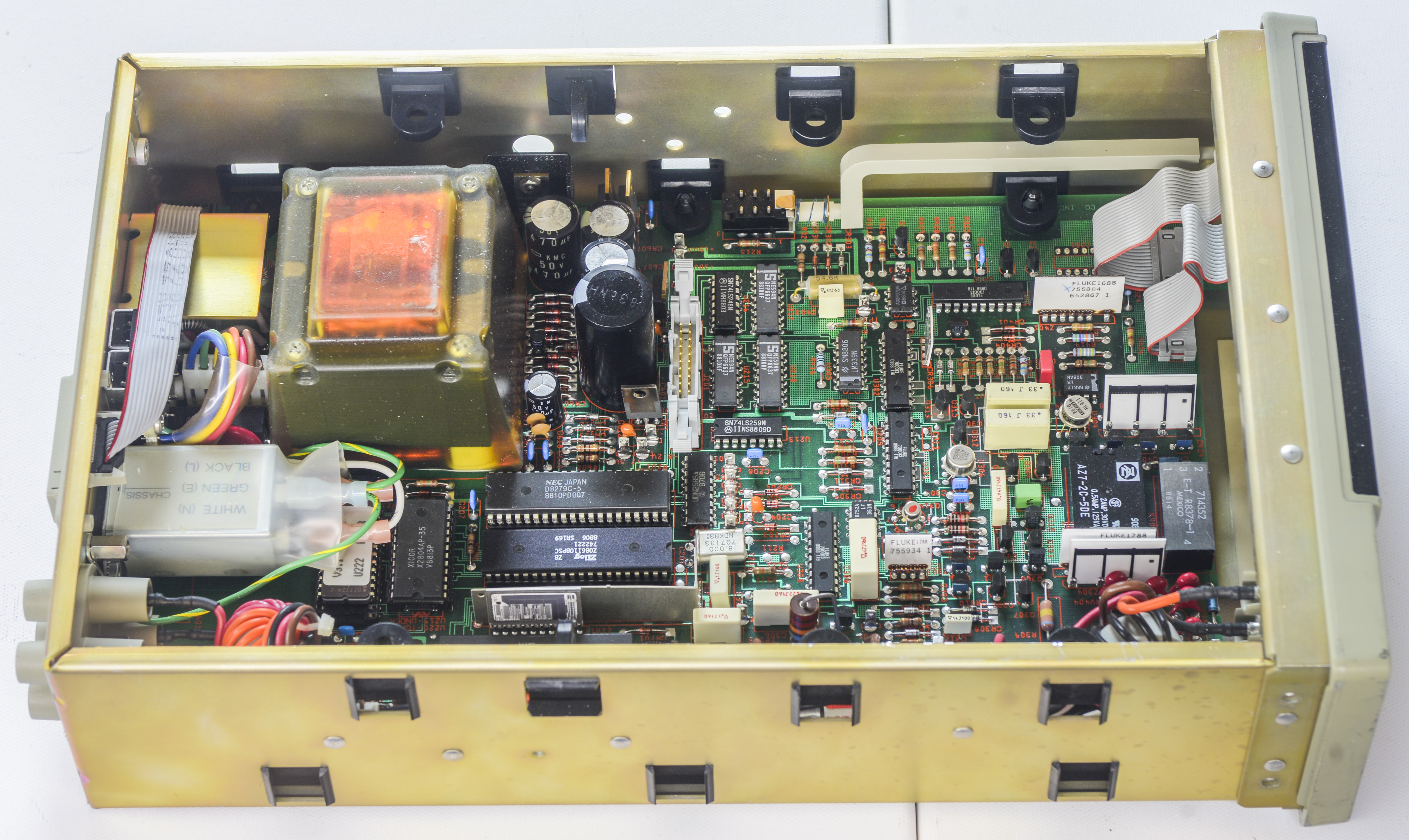
Image 3-4: 8842A with metal cover and AC board option removed
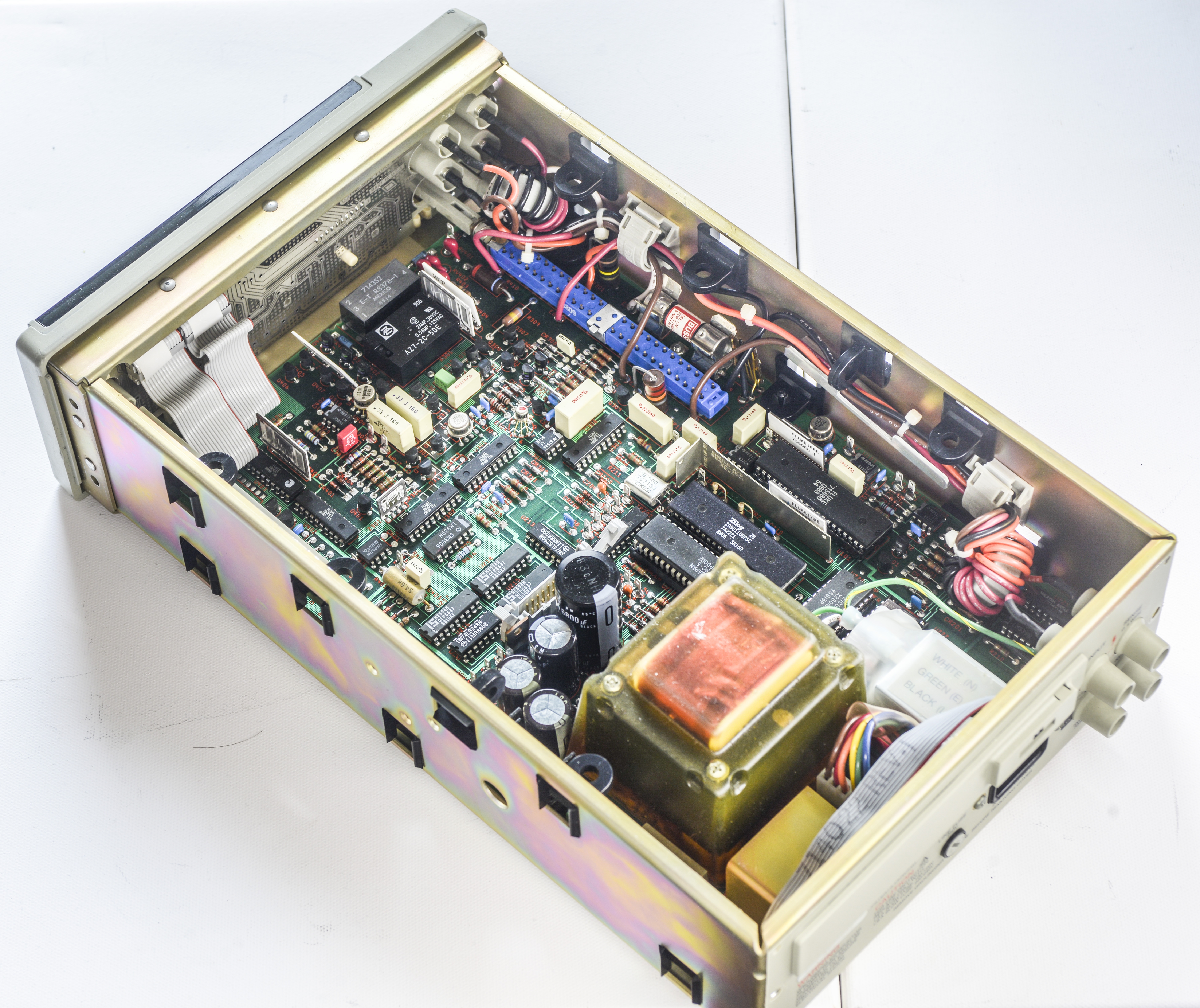
Image 5: 8842A overview from other side
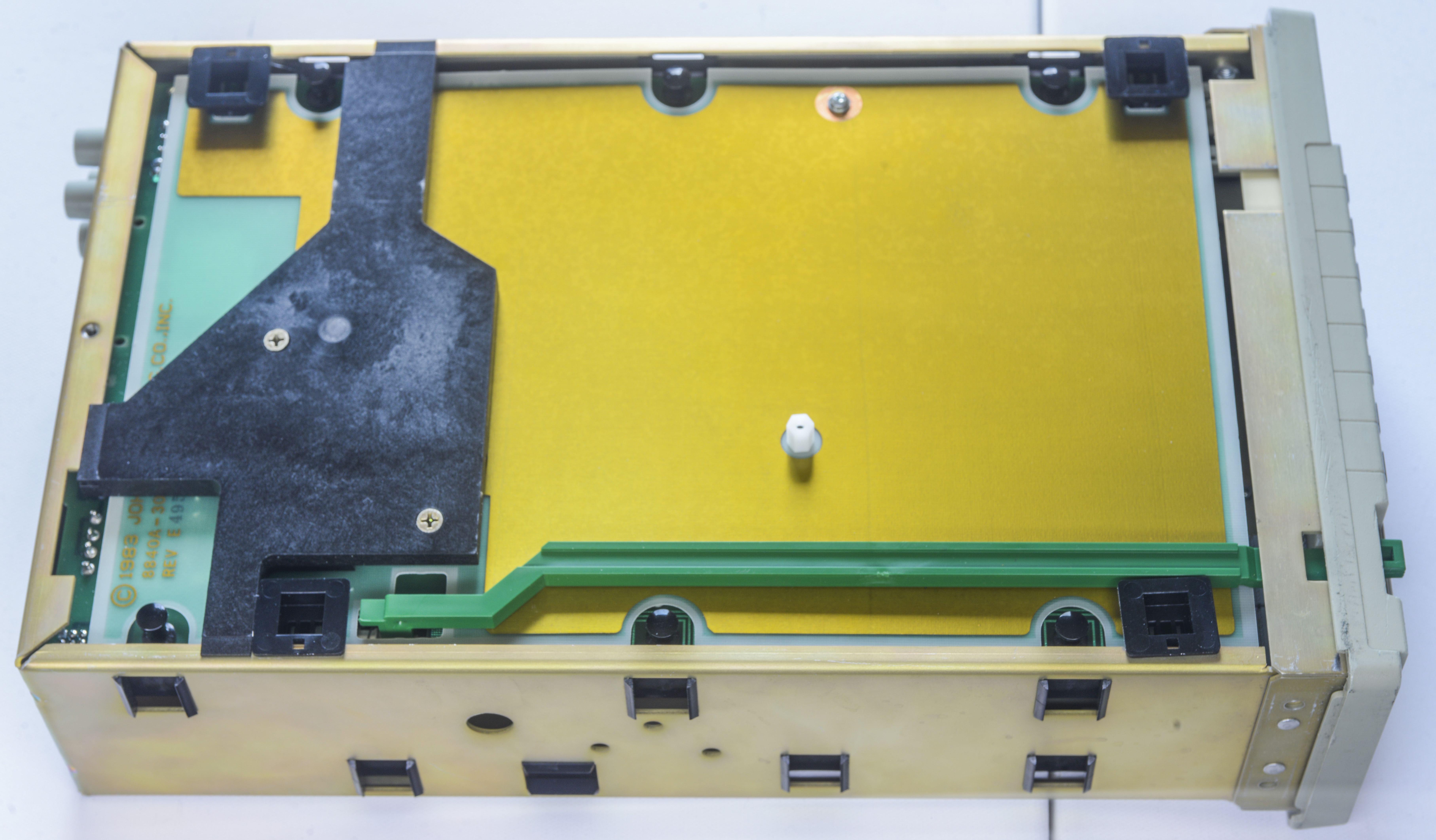
Image 6: 8842A bottom side shield
After removing front panel plastic, it becomes very clear, why repair of this unit make no economic sense.
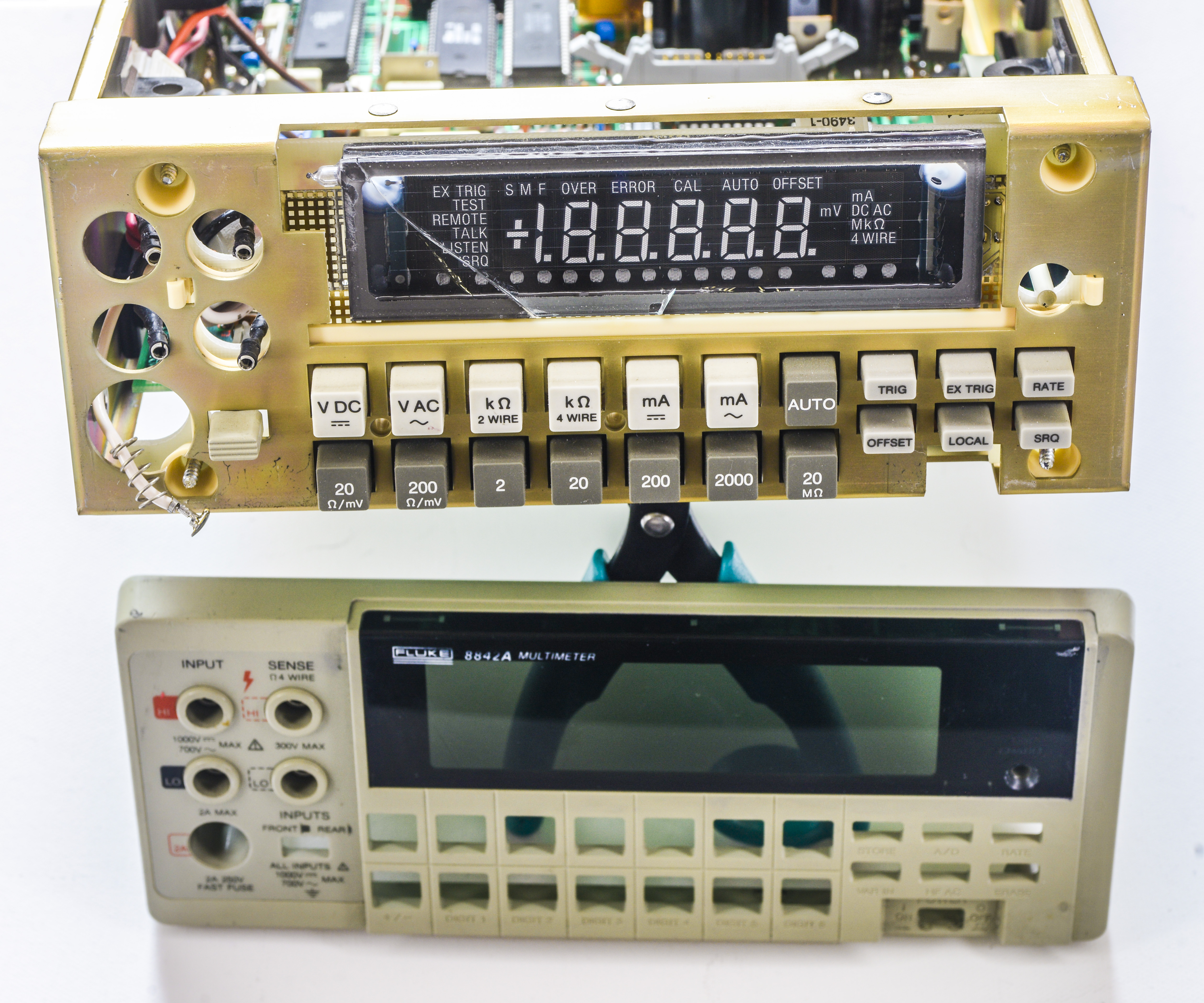
Image 7: 8842A front panel plastic removed. Damage of VFD glass is now very visible.
Buying VFD glass panel or interface card would make this 66$ meter double of the price, due to international shipping costs, so it will be sacrificed for science purposes and donor parts.
Teardown and repair
Now we back to our reader’s meter. It was able to power on, display on it really nice and bright, but on any range and function it would just report OVERFLOW, disregarding state of the input signal. That happened after owner changed track/hold amplifier in attempt of troubleshooting some functions not working right/giving noisy readings.
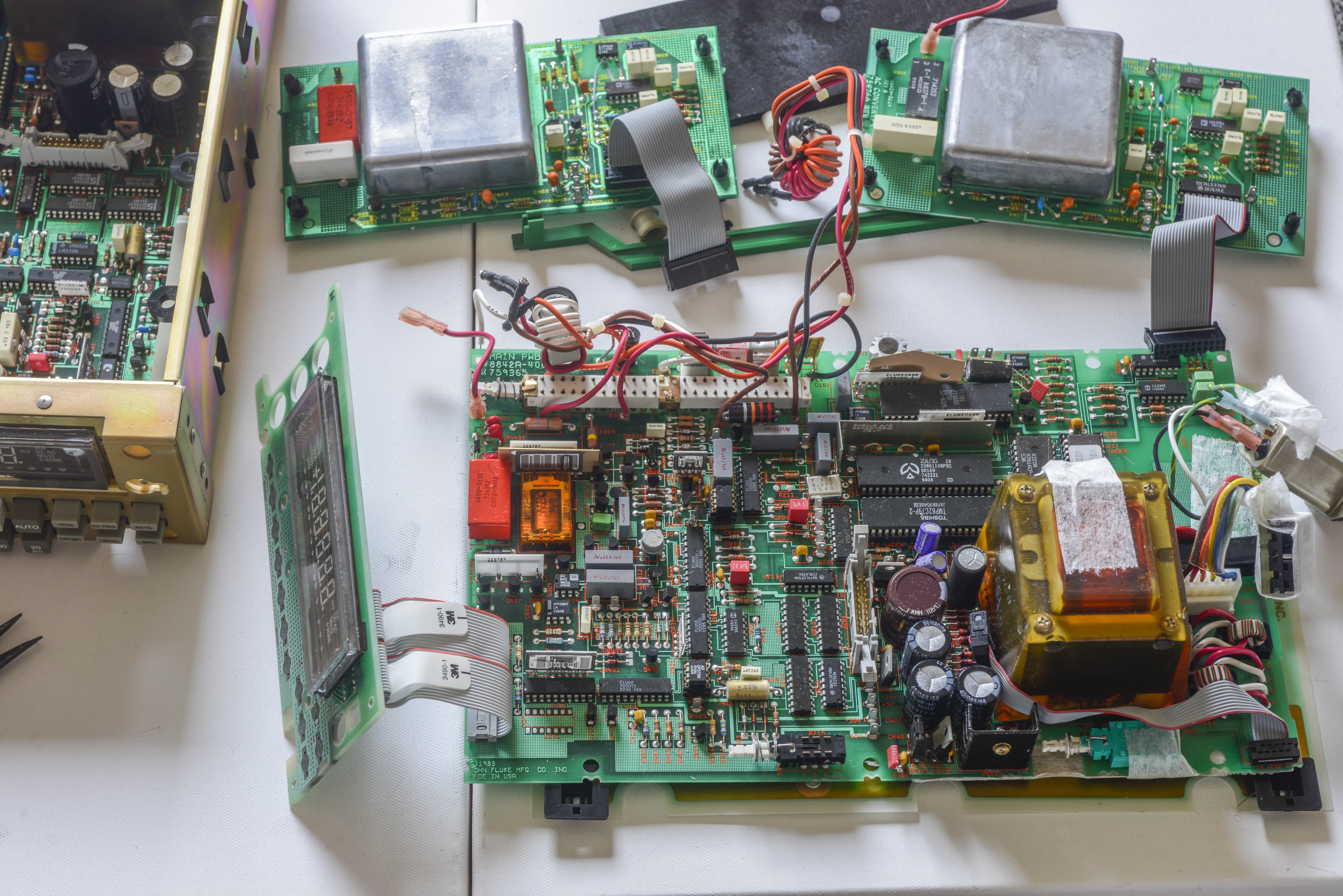
Image 8: 8842A board removed from chassis. TrueRMS AC boards shown on top side
Usually repairing equipment that was serviced before by 3rd party is not such a great idea, however here we knew what was changed, so it’s bit easier. Bulk input power capacitors were replaced with decent series 1st tier brands, some other parts were changed as well, but main question here now is signal path and analog frontend, as we have no readings at all.
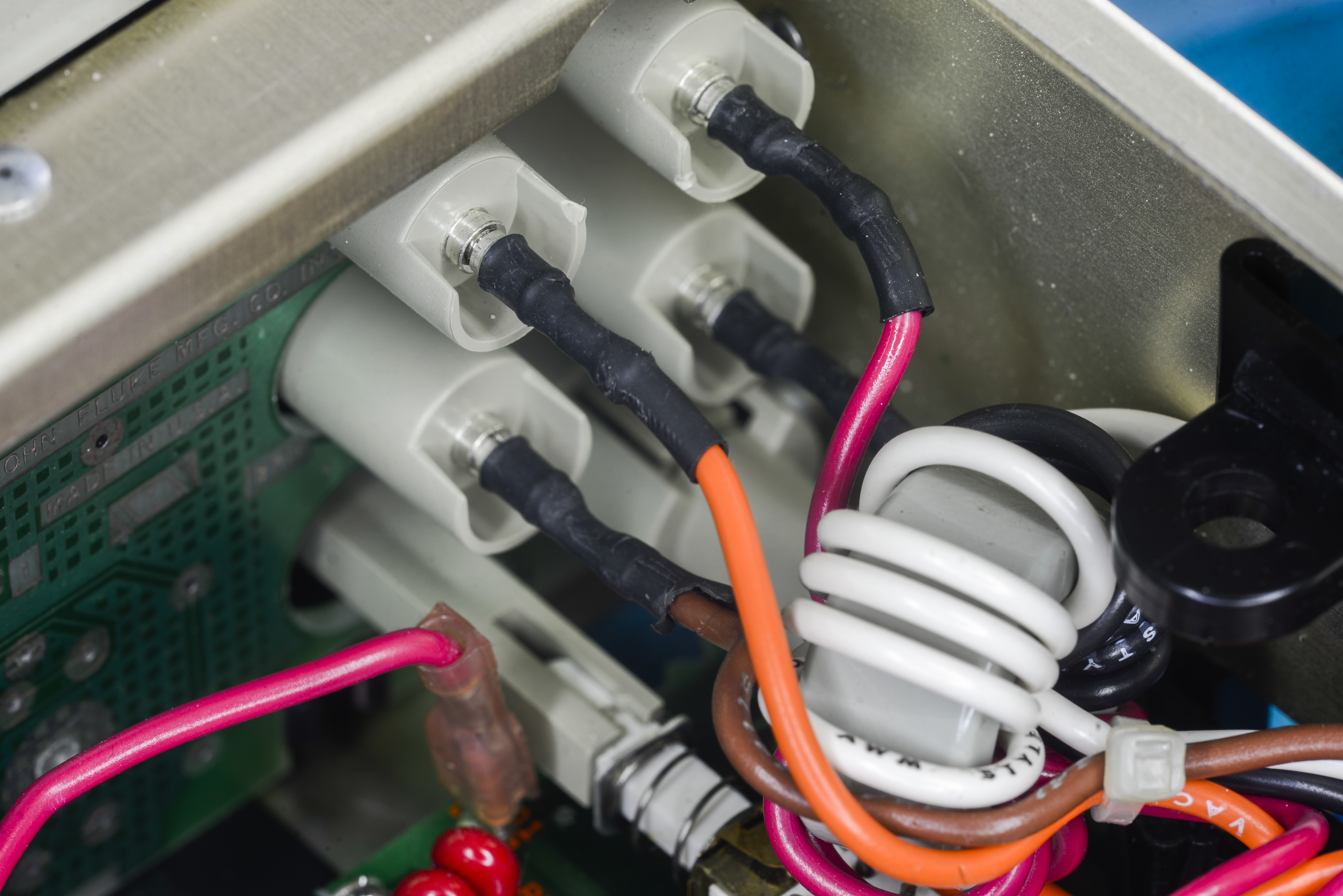
Image 9: Inputs are connected to wiring with silver-plated latching jacks
Because of the accuracy specs of this meter, there is no much need in expensive bare-copper connections. Light layer of plating over the posts will not do much damage at this level of precision, this is low-cost benchtop meter after all, not a metrology beast like Datron/Wavetek 1281 or Fluke 8508A.


Image 10-11: Overview on A/D Converter and input front-end areas
All components in the meter are thru-hole type, none of this modern SMD stuff. It makes probing and testing somewhat easy.
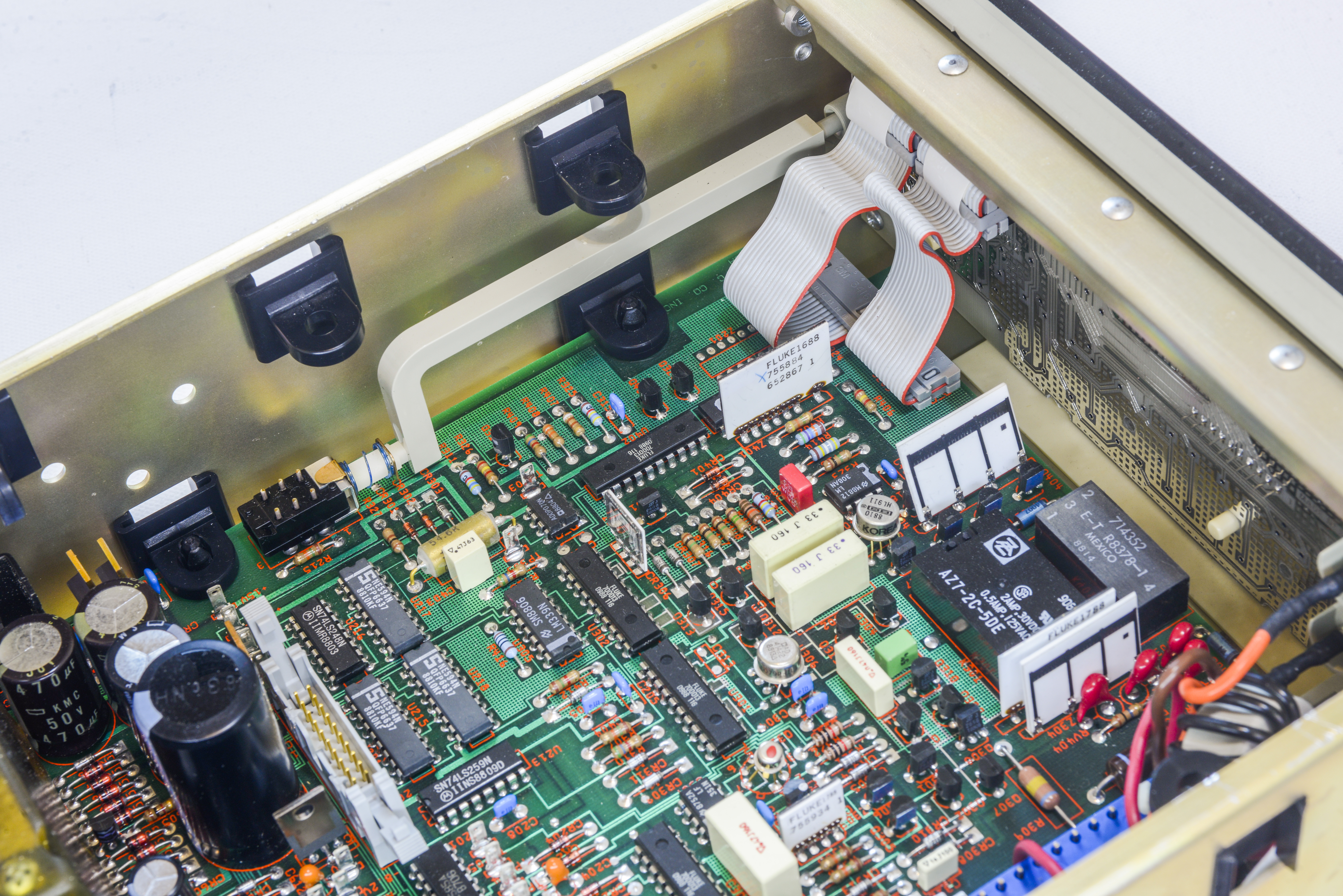
Image 12: Custom Fluke 700013 packages are switches for front-end
Main voltage reference here in 8842A is almighty Linear LTFLU-1, manufactured exclusively for Fluke, based on ideas of Motorola SZA263 REFAMP chip. Older 8842A/8840A meters have Motorola SZA263, while this one have Linear LTFLU-1CH chip, with manufacture code 9050 from week 50, year 1990. That is 28 years ago, and I’m sure this reference can still deliver its stability another 28 years from now.
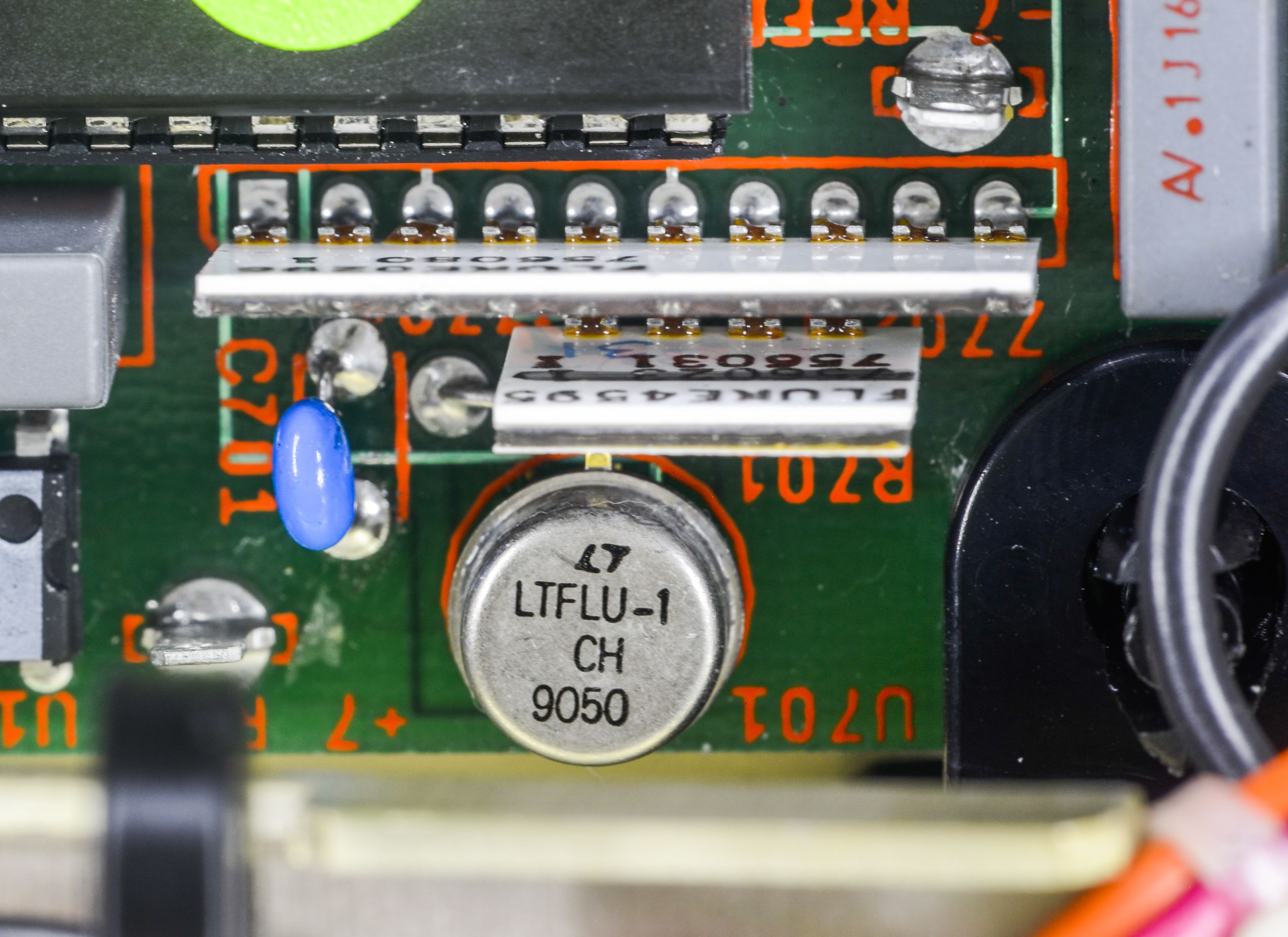
Image 13: LTFLU-1 reference from Linear (now ADI) and Fluke hermetical resistor networks
LTFLU Ref-Amp on high-level consists of an NPN transistor in series with a zener element. When biased properly with correct current, this combination has an extremely low voltage/temperature coefficient. The reference voltage that the can vary from +6.5 VDC to +7 VDC, depends on used working current and actual chip production batch. Also since both zener and transistor are located on same silicon substrate and enclosed in hermetic package, they are well thermally coupled and protected from ambient humidity. This allows to improve stability over long time spans, isolating reference chip from ambient environment variations.
Unlike LM399 used in Fluke 8846 this non-ovenized REFAMP reference together with matched precision resistor network have potential to provide 7½-digit stability and used in many high-end Fluke instruments. In fact, absence of oven also means there is very little time needed for meter to reach the specified uncertainty from cold powered off state. Hours long warm-up time is not an issue for long-scale 8½-digit meters as they meant to be running 24/7, but is not a welcome thing in benchtop daily meter. And 8842A takes care of that with fast ready to work speeds.
The most known examples of what LTFLU/SZA263 chips are capable of are top-level Fluke 732A/732B/732C DC Voltage reference standards, Fluke 55xxA and 57xxA series calibrators, Fluke 8508A DMM and 5790A/5790B AC measuring systems.
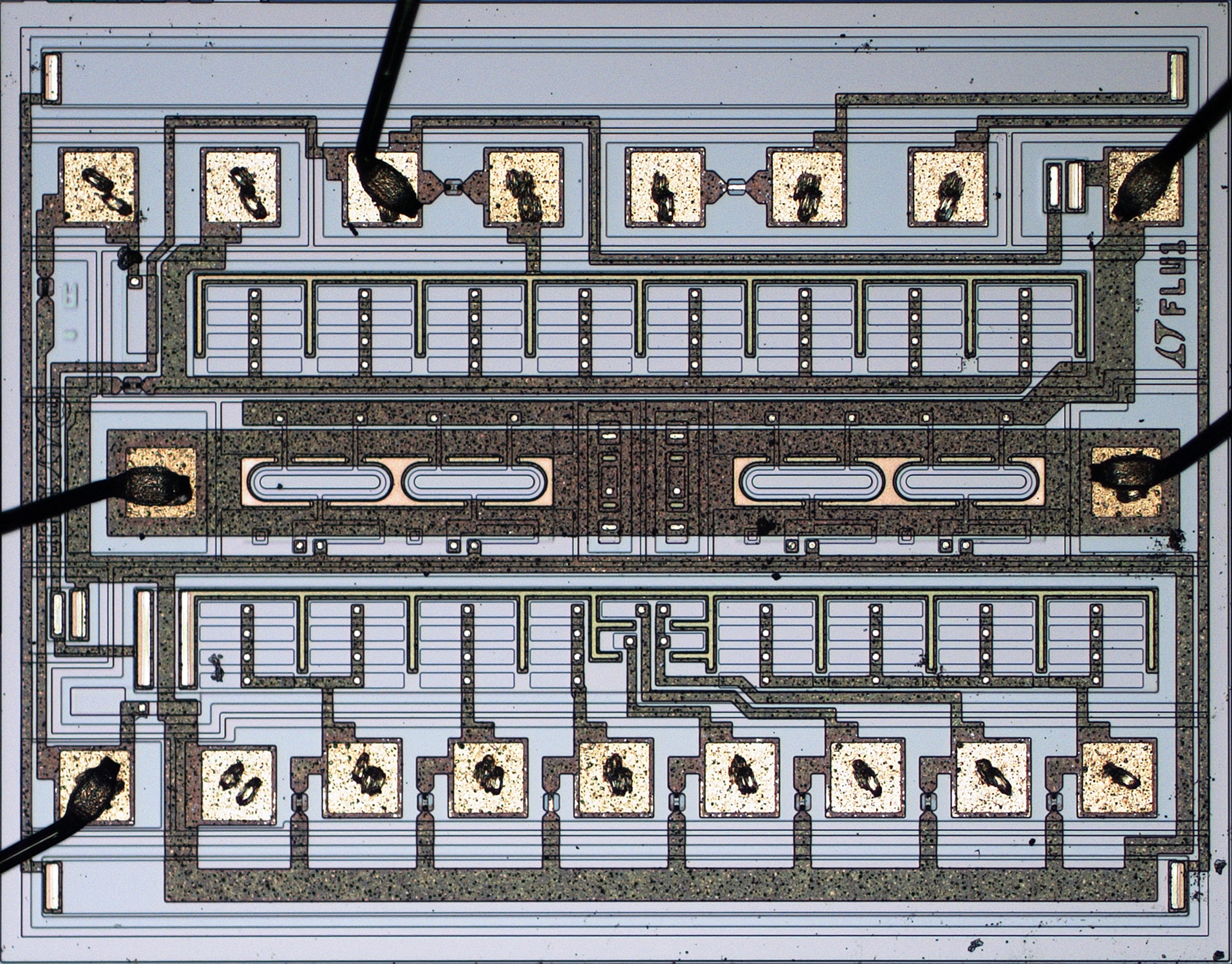
Image 14: LTFLU-1CH die photo. Courtesy branadic (Dipl.-Ing. A. Bülau) from the EEVBlog forum
On the die photo we can see much more complex design than just diode and transistor. Devil is in details, when it comes to most stable voltage reference designs.
Also for educational purpose schematic section from Fluke 57LFC calibrator shown below, confirming even very same 8842A resistor part numbers. Reuse of same design blocks by professional analog engineers often a common practice, instead of reinventing the same wheel every time from the scratch. Also this helps to unify the production and testing process, as these chips are not cheap to performance grade and validate.
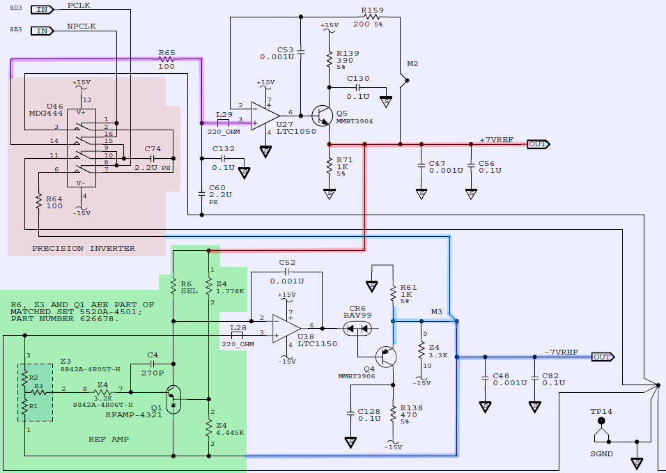
Image 15: Fluke 57LFC using same reference REFAMP and resistor networks Z3,Z4 as 8842A
First troubleshooting step is to check all power supply rails to confirm all power is OK.
Capacitors and voltage regulators were already replaced by the meter’s owner, so this was just a quick check to make sure we have no power issues.
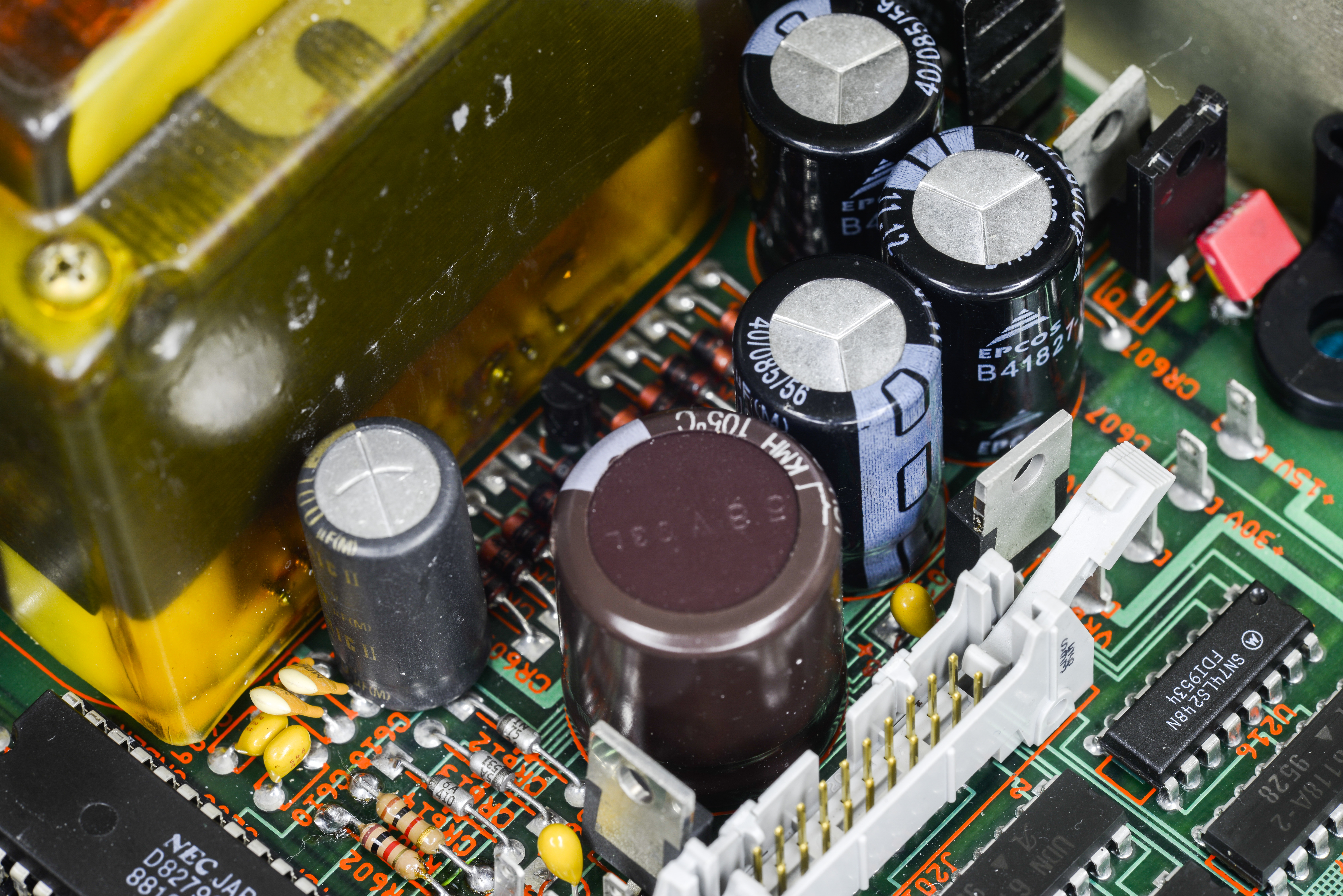
Image 16-17: Linear power supply regulator and calibration switch
Power tested just fine, no problems detected with any of the rails, tested according to instruction manual.
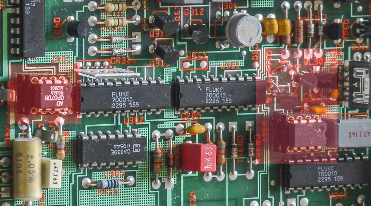
Image 18: Sick 8842A close-up on altered components, marked red
Next circuit in the list is special input JFET stage Q314, used in track/hold main amplifier. It was a suspect, because original quad-JFET hermetically packaged hybrid was replaced with pair of 2SK170 JFETs.
Using discrete unmatched JFETs is immediate red flag for precision design, as JFETs and MOSFET devices usually have bad matching, which usually is in percent. For differential amplifier input stage like here this will cause large offsets and ruin the performance.
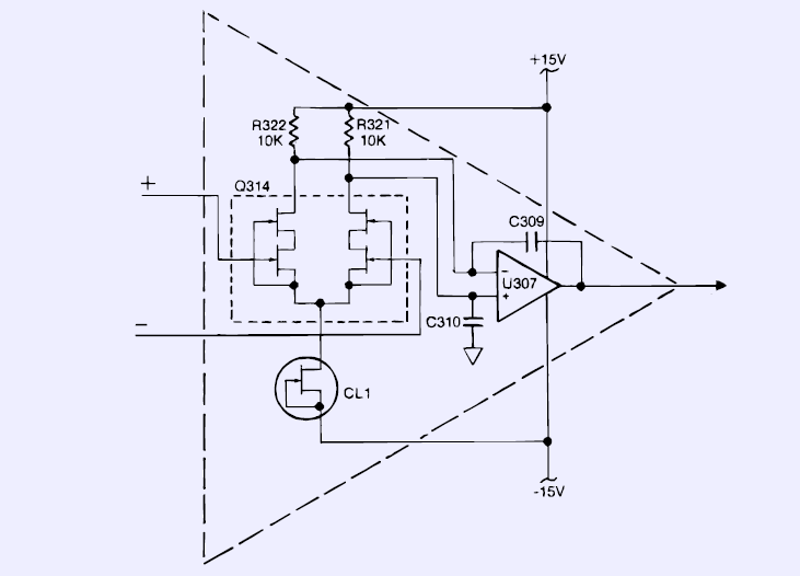
Image 19: Track/Hold composite amplifier overall design concept
But before we dive in deep, here is block diagram of the composite amplifier for track/hold circuit, that sits between analog front-end section and ADC itself. Purpose of the T/H amp is to provide stable signal representing unknown input for A/D while latter is busy with conversion cycle. This circuit also provide gain of 100 for 20 mVDC, 20 Ω and 200 mA ranges and a gain of 10 in the 200 mVDC, 200 Ω, and 2 ADC ranges. For this different sections of custom Fluke hermetical thin-film hybrid resistor Z303 connected to feedback. Take a look on detailed circuit diagram from service schematics:
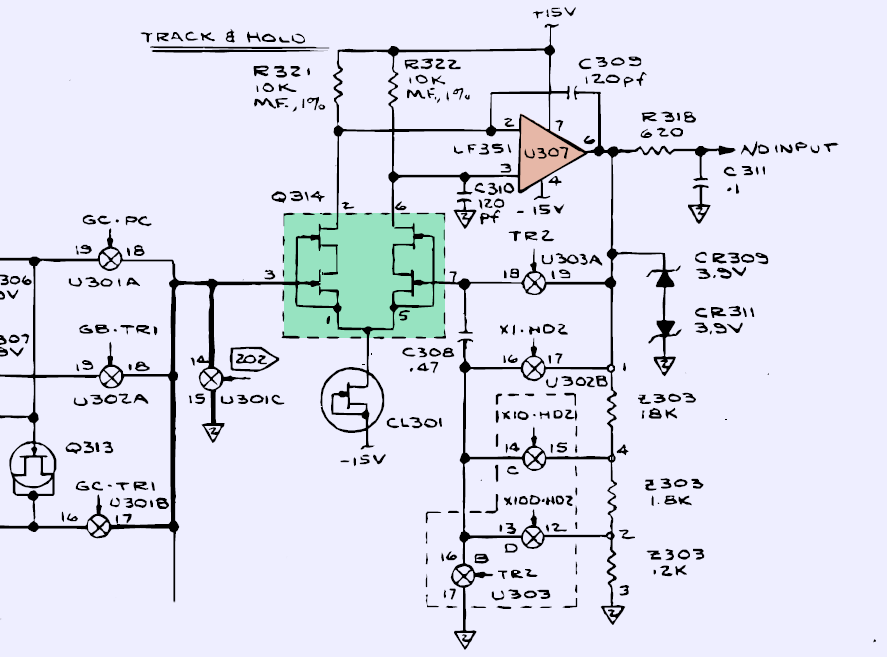
Image 20: Schematics of T/H amplifier. Custom quad JFET assembly is marked in green box.
Q314 is the special JFET array, carefully selected by Fluke for balanced inputs. It is not cheap to find and match four JFETs in discrete array, due to differences in manufacturing and even JFET die temperatures. The rest of T/H circuit consists of the amplifier U307 LF351 in DIP8, T/H film capacitor C308, custom Fluke-branded quad analog switches U301, U302, U303, current sink CL301 and rest of associated components.
As shown on schematics the whole block functions as an op amp, with Q314 supplying additional gain with low noise. Q314 is custom obsolete JFET array, rather impossible to buy today as exact replacement. But no worry, donor unit to the rescue. With help of oscilloscope output of the U307 was measured and was found at -8.x VDC, no matter what input signal is applied. No good at all, A/D Converter input working range is +/-2V only!
So as first attempt for hopefully easy and quick repair, we have replaced transistors in position Q314 with the donor quad JFET from broken Fluke 8842A. However, that does not help, and conditions in meter and output voltage remained same -8.x VDC. Next step – replace the opamp U307. It was socketed by the owner in hope to try different opamps (in hope to resolve other issues, perhaps?). Use of sockets in precision circuits often not a very good practice, except for prototyping purposes. We will see why later on, I promise. For now, just replaced opamp in socket with LF351 from the donor meter, but outcome was same, and this effort was futile.
Now let’s take a step back and check the overall diagram of the unit.
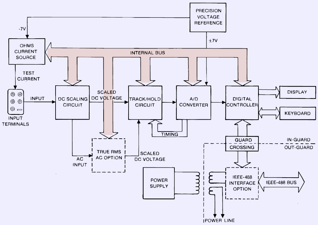
Image 21: Block diagram of Fluke 8842A multimeter
We have input front-end that handle signal levels and switching of the ranges/functions and include protection circuits and components. It sits right before the T/H amplifier so if the input signal is clamped to either rail or wrong level, then our T/H amplifier will not give correct levels either. Just as a precaution, switches U301, U302, U303 were also replaced, but as expected that did not provide any improvements.
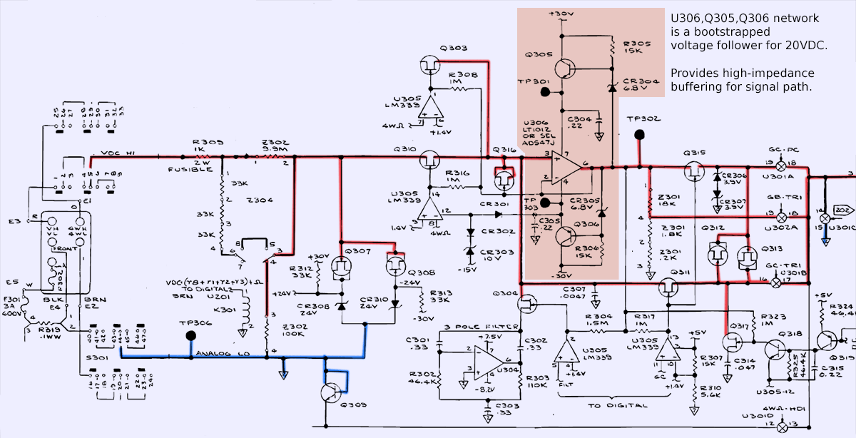
Image 22: Schematics of the input front end amplifier and circuitry. VDC HI path highlighted in red.
Time for a closer look on the input stage. One way to troubleshoot input front-end is with known and stable DC voltage at the input, and tracing each step to see what happens to signal along the path. Because we understand the expected behavior of the circuit, it is possible to compare actual circuit measurements with correct expected values, to determine if there is a problem with input front-end. We used calibrated 3458A as check standard to verify that input signal is correct, but any second DMM will work in this case.
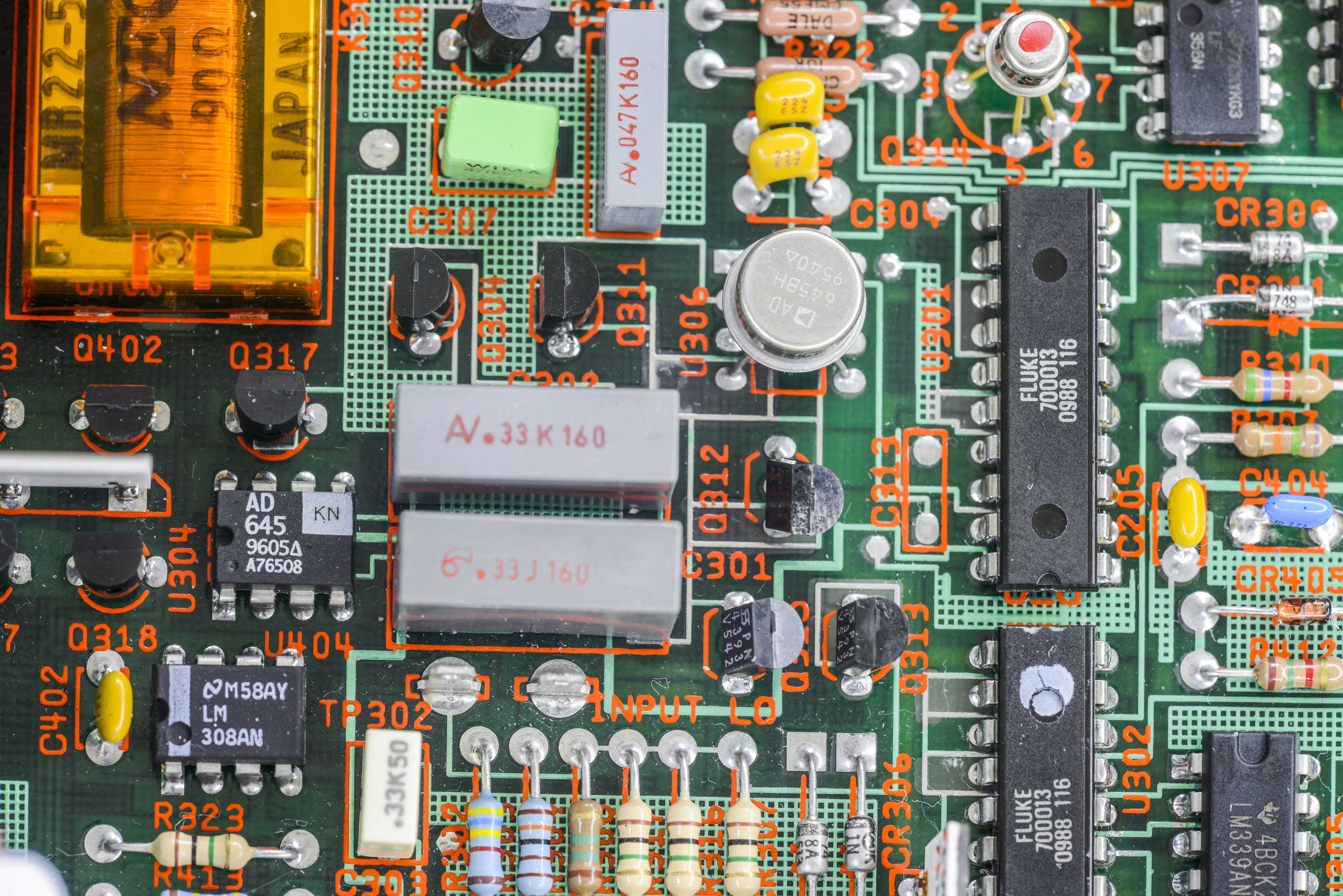
Image 23: Bootstrapped input amplifier in hermetic package
U306 in meter actually do not match the schematics in the manual, it is hermetically packaged Analog Devices AD645BH. This device sports with less than 15 fApk-pk current noise and 2.5 µVmax voltage noise in 0.1-10 Hz band, which is very good for FET amplifier. Stability of this opamp is also very good, at less than 2 µV/°C, which translates into max drift ±1 ppm/°C of the input amplifier. This kind of performance is overkill for just a 5½-digit DMM.
Known DC Voltage was supplied to the input HI and LO terminals, and about same DC voltage was measured at the amplifier output test points TP302 and LO TP306. Voltage levels 100mV, 1V and 10V were tested, and range switching output was also confirmed OK. So no problem with the input switching and high impedance bootstrapped input amplifier, the signal levels delivered to T/H amp are correct, and the problem is inside T/H or A/D converter. Just to rule out digital control issues, swapping A/D ASIC, digital memory and LM339 comparator was done, but that didn’t change anything either, meter still show OVERFLOW state in all ranges.
Now remember, we had socket on top of the socket in the T/H amplifier and current source opamp? It did not occur to me at first, that there could be life or death issue, so only few hours after deep into troubleshooting, sockets were actually desoldered to check if any PCB problems under them. And yes, there was some scary looking flux goo residues under the DIP socket. PCB was immediately cleaned with IPA and new opamps for T/H amplifier and ohm source were soldered directly into PCBA. I did not have LF351 in stock, so used bit better LF356 instead.
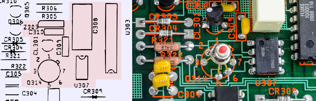
Image 24: 8842A T/H without any sockets and with new good parts. Q314 borrowed from donor 8842A and tested OK by SMU .
And bingo, we got the readings on display now!
Now that the input front-end and track/hold amplifier working correctly, known stable reference voltages can be supplied to the meter A/D converter to perform further tests.
| Test signal | Measured value | Comment |
|---|---|---|
| +1.0000000 VDC | +0.96353 V on 2V range | -3.65% error, way too big even for uncalibrated meter |
| -1.0000000 VDC | -1.03405 V on 2V range | +3.41% error, way too big even for uncalibrated meter |
| +1.0000000 VDC | +0.6135 V on 20V range | This voltage should be close to 2V range result |
| -1.0000000 VDC | -1.0024 V on 20V range | Only this configuration is somewhat close to true value |
| +10.000000 VDC | +9.63564 V on 20V range | Same reading error as 2V |
| -10.000000 VDC | -10.3422 V on 20V range | Same reading error as 2V |
Table 3: Bad A/D test results with voltage externally supplied to TP203 and LO.
Perhaps bad calibration after replacement new parts? Well, self-test procedure does not agree with that weak theory, self-test steps 7, 15,16,17,18,19 fail hard every time, and attempted calibration also was giving permanent errors on -1.01 A/D linearity calibration. So no, meter is still not functioning as expected.
Time to test signals again with external meter, by measuring voltage at Track/Hold input and outputs. That test confirmed that signal is correct level after front end in 8842A, but output of the T/H amplifier was jumping back and forth at lower incorrect voltages. So next suspect is A/D converter itself.
Fluke uses special patented recirculating remainder A/D conversion technique. Patents are great resource for better understanding this low-cost precise A/D converter design.
Patent US3703002 – A/D converter using recirculation of remainder, Nov 14, 1972
Patent US4539550 – A/D converter using recirculation of remainder, Sep 3, 1985
Patent US4535318 – Calibration Apparatus For Systems Such As A/D Converters, Aug 13, 1985
Patent US4555692 – Error Correcting Apparatus For Systems Such As A/D Converters, Nov 26, 1985
Interesting side note – this exact recirculating remainder A/D converter is also used in 5700 series calibrators. Those machines able to produce 7½ setting resolution because ADC is only used as null detector, so it’s full-scale accuracy, own resolution and linearity is not too important factors. Ultra-linear PWM DAC in those instruments and references are the performance determining parts.
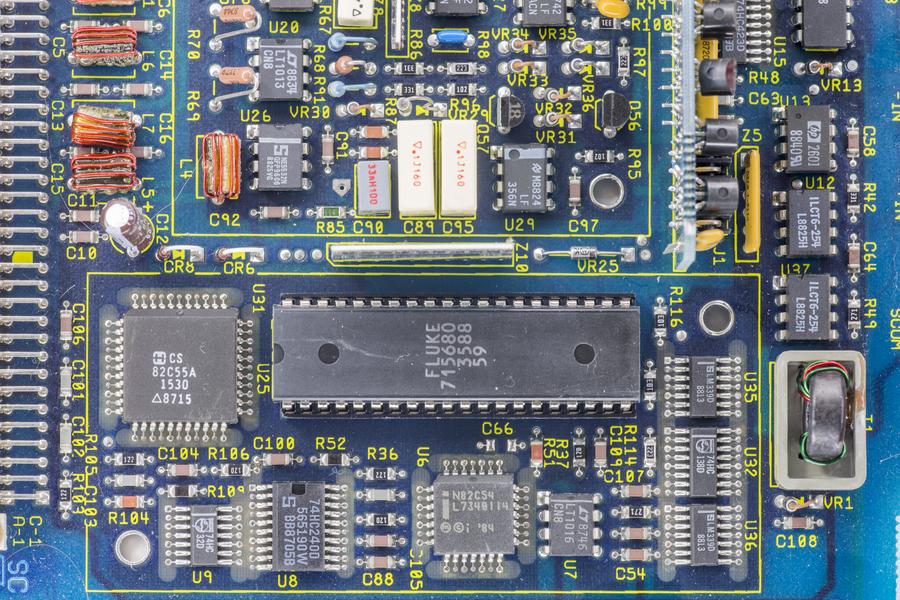
Image 25: Same A/D converter, used as null detector in Fluke 5700A calibrator DAC A11 assembly
Now, back to the sick meter. We have proven that A/D converter chip is working correctly, by using known good chip. LTFLU-1 reference outputs and related inverter also provided clean and stable +6.9998 and -6.9996 voltages, no problem with voltage reference.
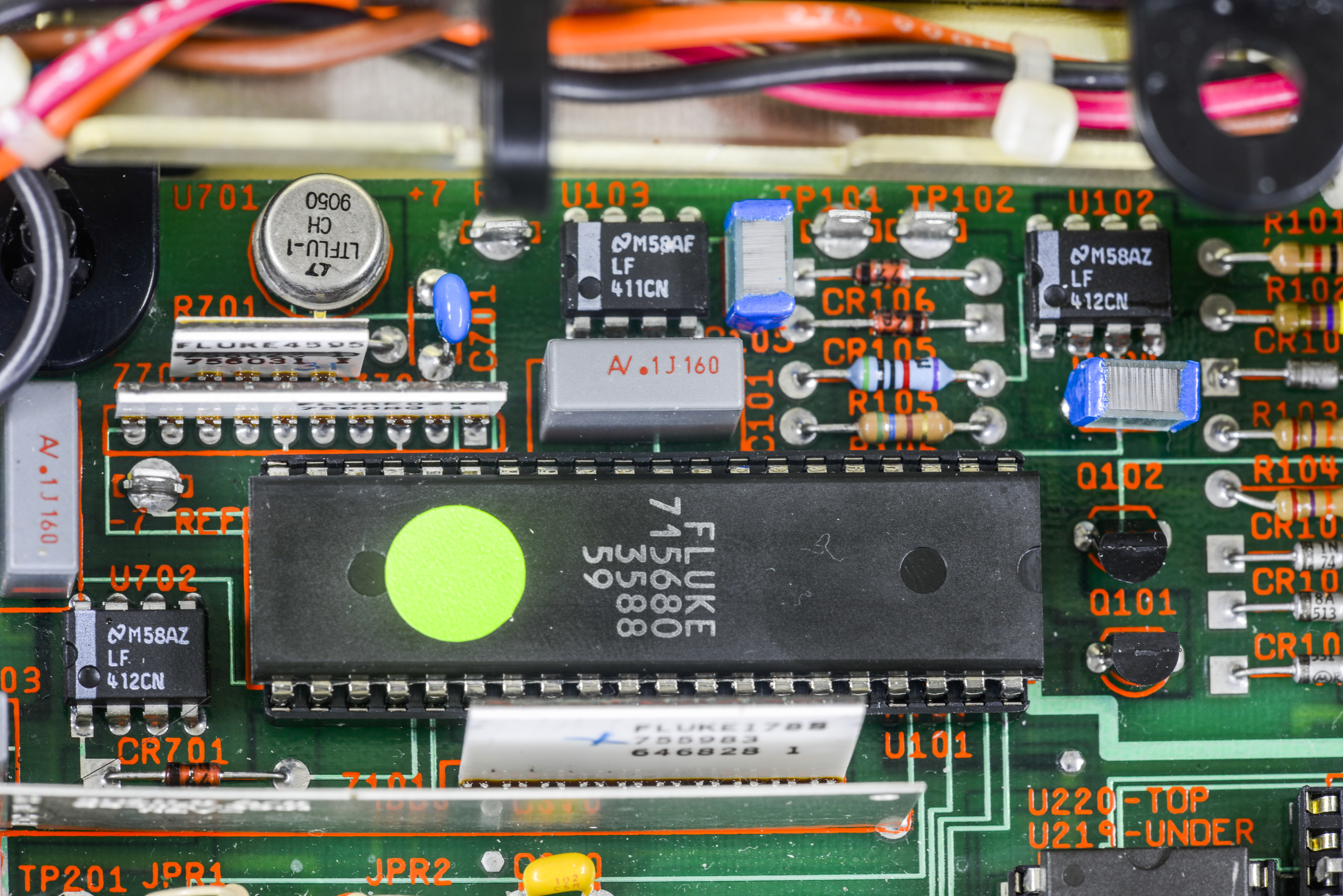
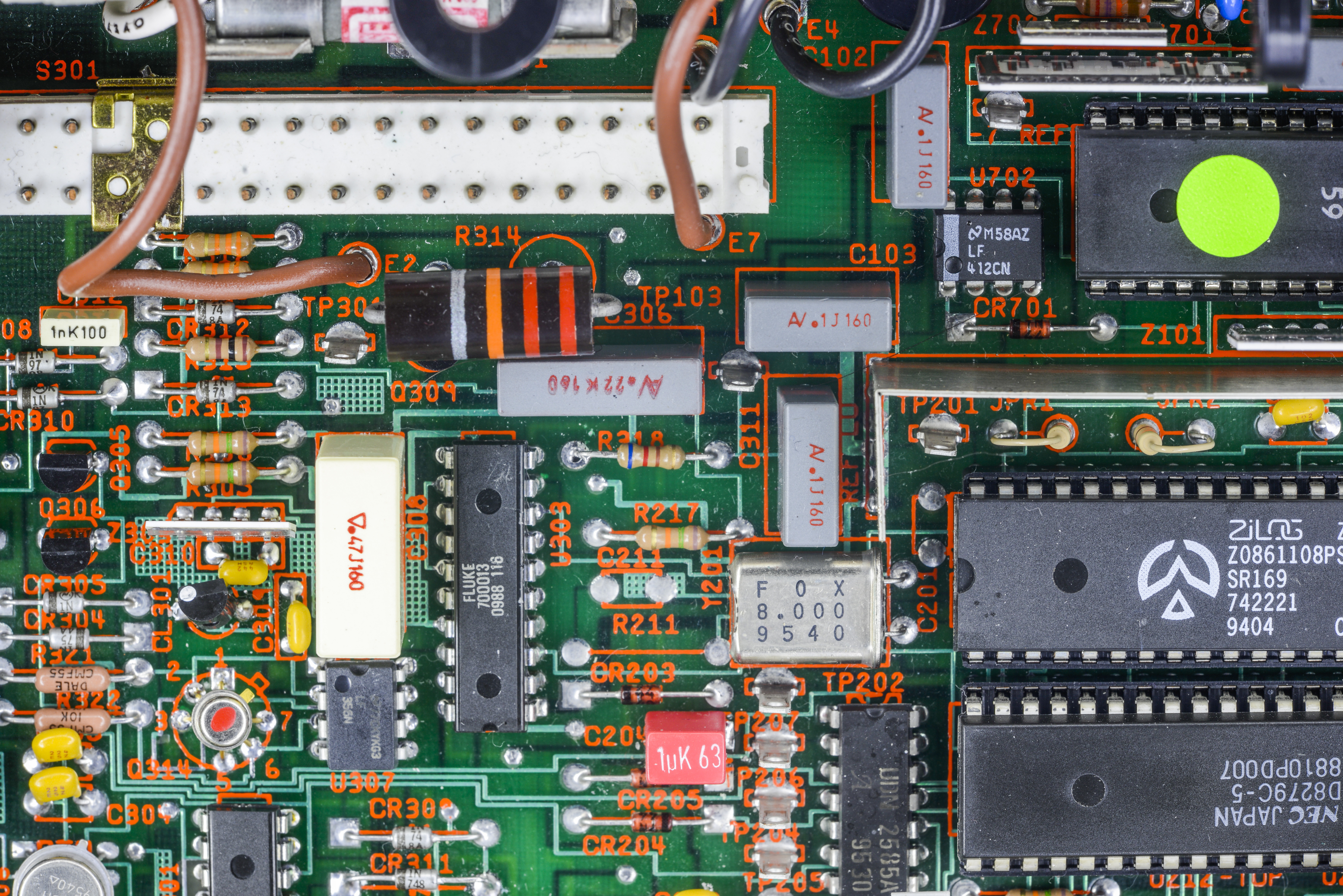
Image 26-27: A/D converter ASIC, voltage reference and network resistors arrays.
The remaining question goes to Fluke 755983 resistor network Z101 that sits right next to A/D ASIC Fluke P/N 715680. This network determines linearity of the A/D conversions by providing very stable resistance ratios. This network consists of bit resistor ratios for binary ladder network, DAC amplifier resistors and A/D amplifier for unknown signal comparison.
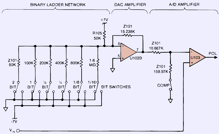
Image 28: Diagram of A/D converter stages. Z101 resistor network is the culprit
Careful inspection hints to the obvious problem, highlight by red arrows. Oops!
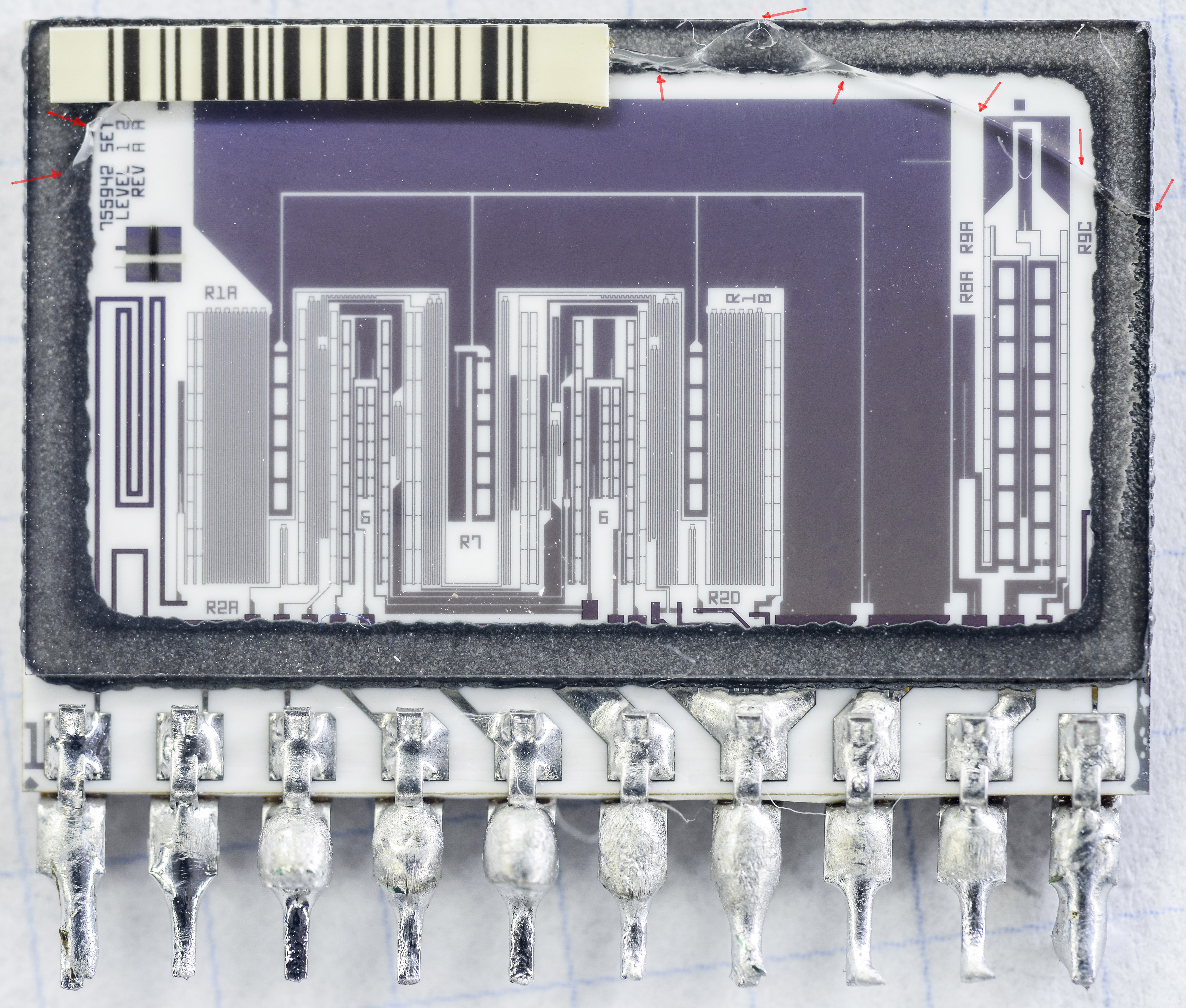
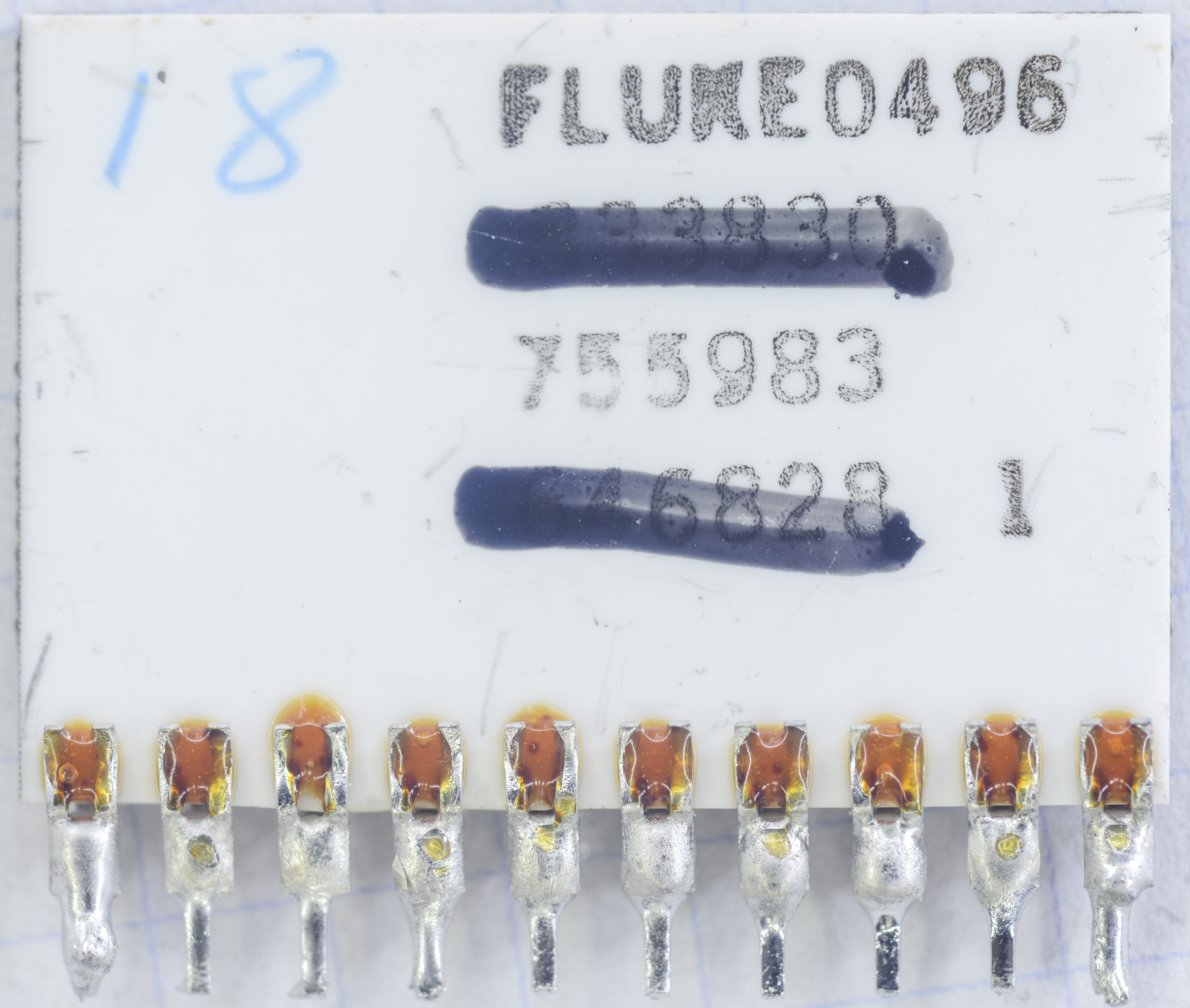
Image 29-30: Damaged Fluke 755983 resistor network hybrid, made in 1996, week 4
Indeed, top glass cover has major cracks, so the seal is broken and ambient humidity affected the stability of thin-film resistive layer. Can this be a solution for our problems? Lucky us, we have donor meter with this resistor network to replace.
After replacement of this network with good one from the donor meter, correct readings from the meter were obtained, yay!
| Test signal | Measured value | Comment |
|---|---|---|
| +1.0000000 VDC | +1.00015 V on 2V range | +0.015% error before calibration |
| -1.0000000 VDC | -1.00014 V on 2V range | +0.014% error before calibration |
| +1.0000000 VDC | +0.9995 V on 20V range | -0.05% error before calibration |
| -1.0000000 VDC | -0.9998 V on 20V range | +0.02% error before calibration |
| +10.000000 VDC | +9.99986 V on 20V range | +0.0014% error before calibration |
| -10.000000 VDC | -9.99988 V on 20V range | +0.0012% error before calibration |
Table 4: Fixed A/D test results with same voltage externally supplied to TP203 and LO.
No more self-test errors detected, even before the calibration adjustment, every test is good!
Few other magical custom resistor networks were removed from donor meter for further in-house projects and experiments. Those will be covered in separate articles later.

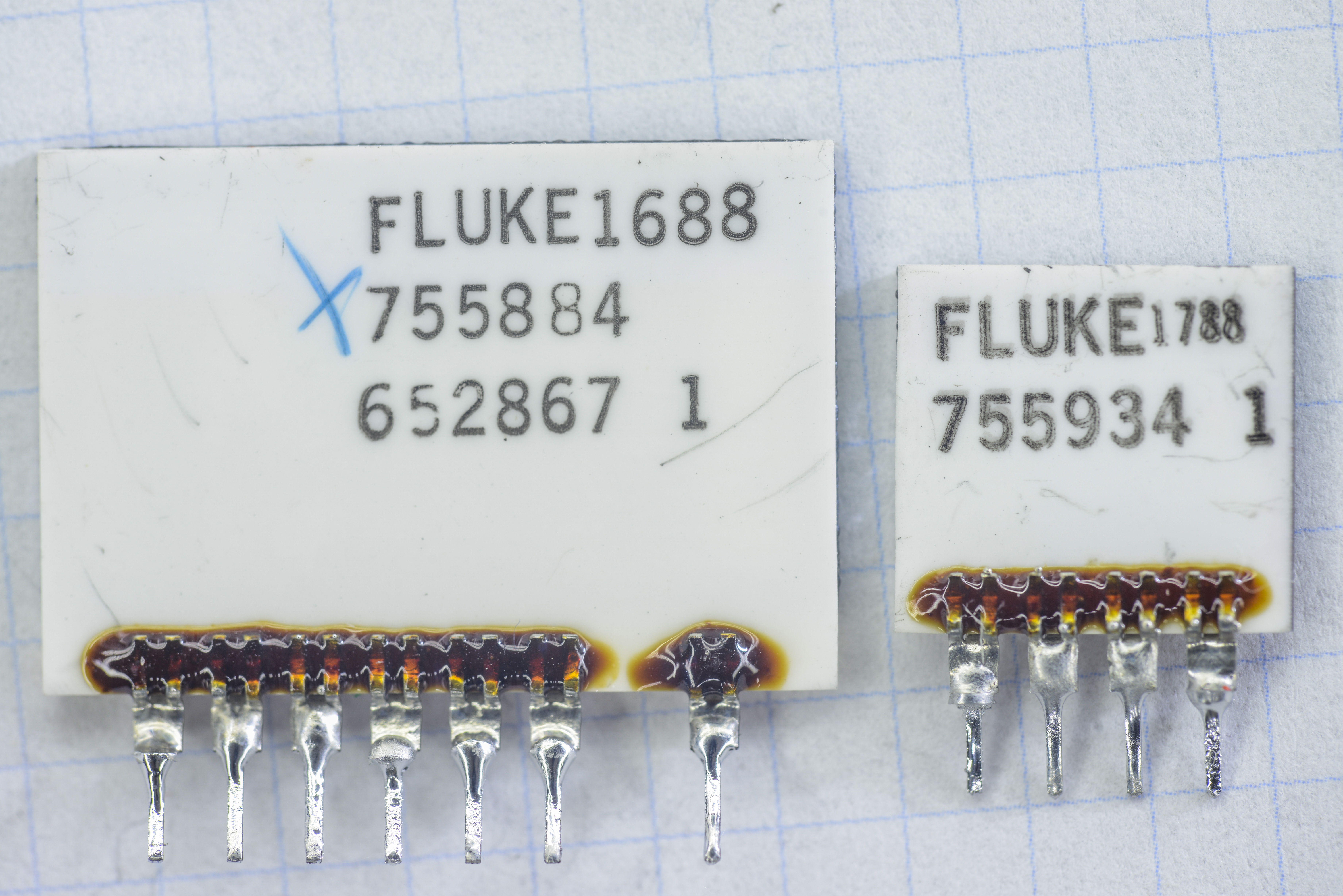
Image 31-32: Few more resistor networks from donor Fluke 8842A unit. Fluke P/N 755884 and 755934
Now we can connect AC TrueRMS option module and test it as well. Take a look on it first:
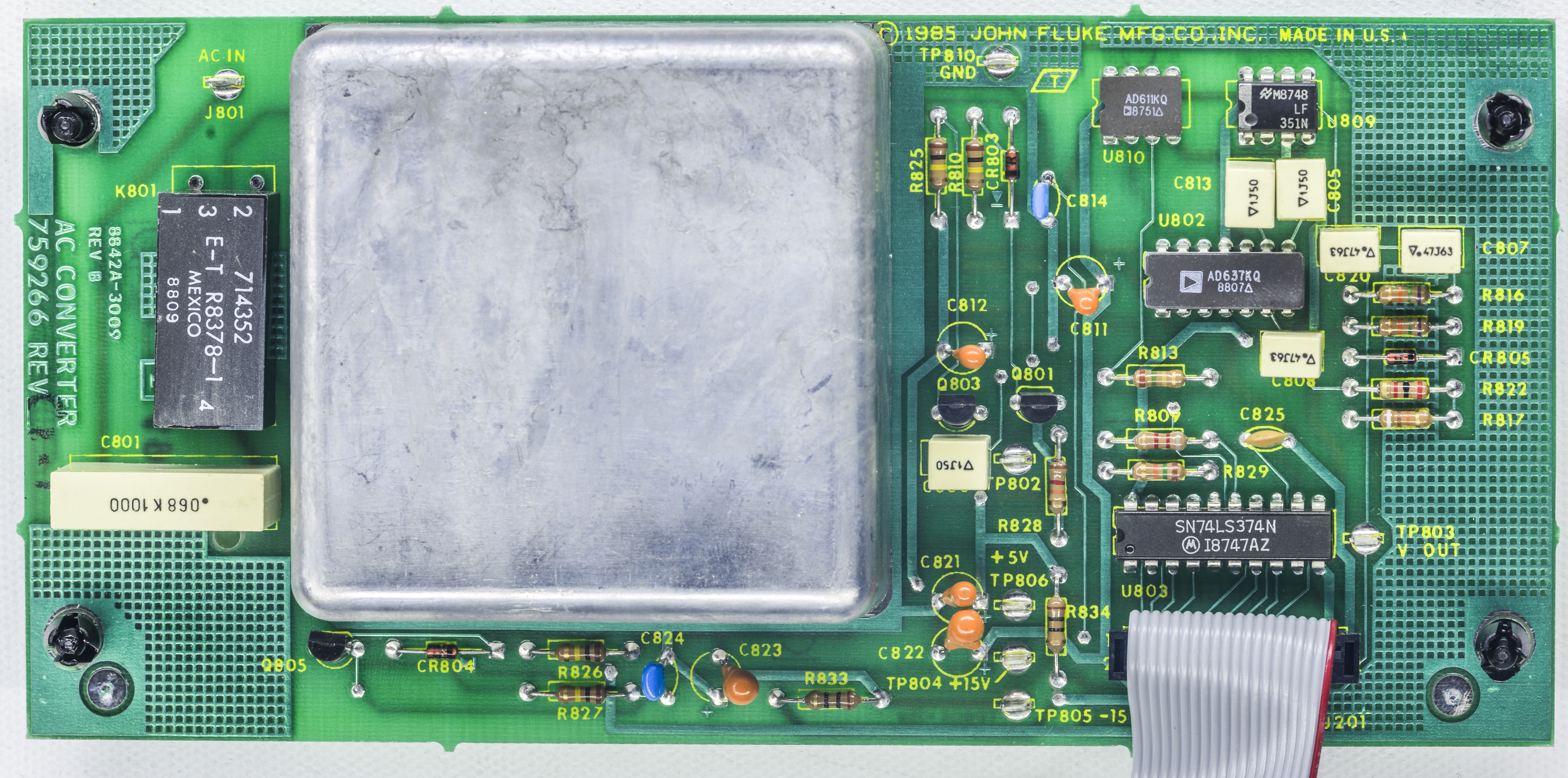
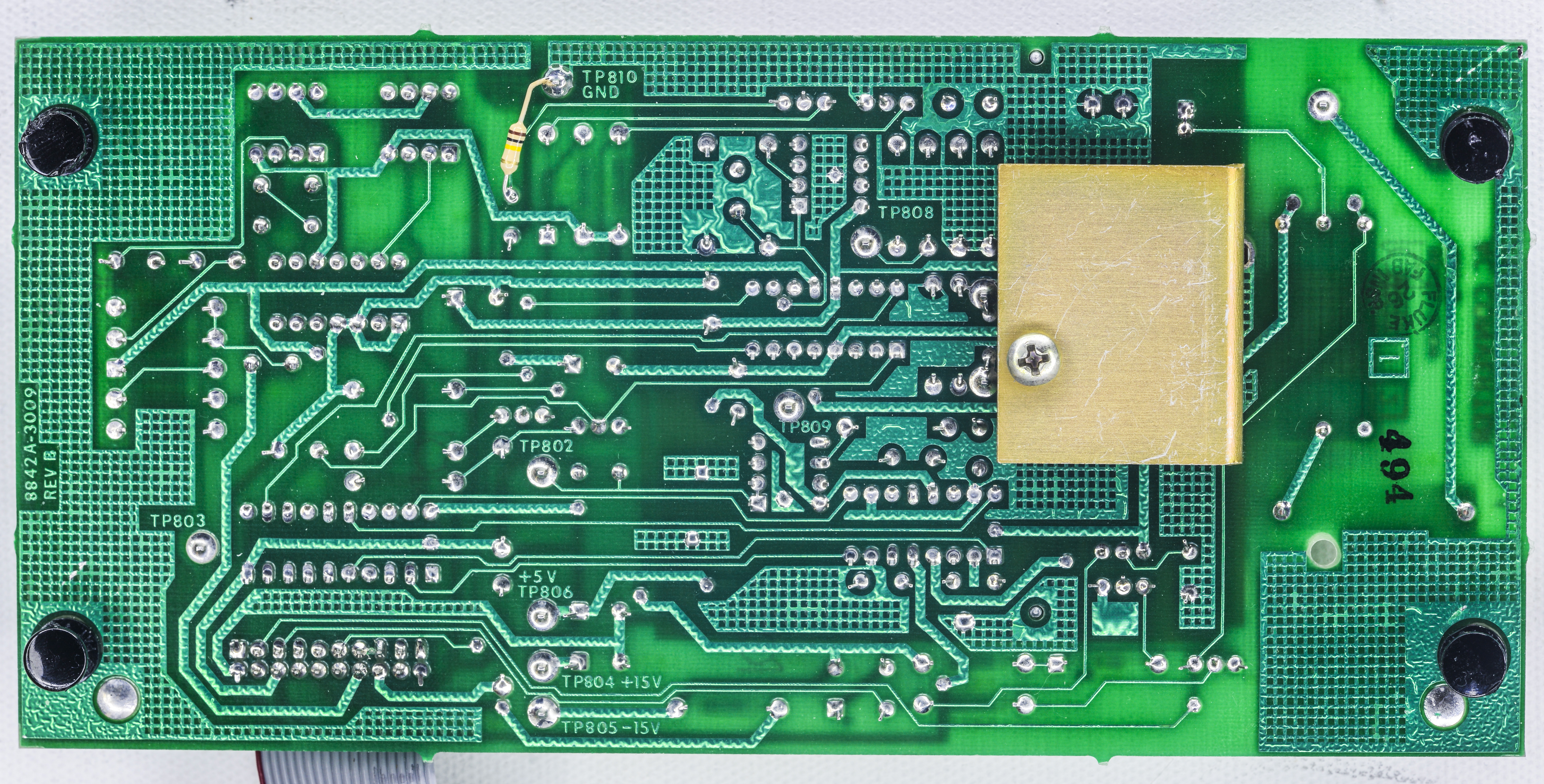
Image 33-34: Fluke 8842A-09 TrueRMS option module PCBA for ACV/ACI functions
Purpose of this module is to accurately convert input AC voltage signal into accurate DC level that is presented to DMM measurement circuit.
Heart of the module is Analog Devices AD637KQ TrueRMS AC to DC converter IC. There is also AD611KQ and LF351 opamps sit nearby. Black rectangle part on the left side is ELECTROL reed relay. Newer version of AC board has COTO reed relay instead.
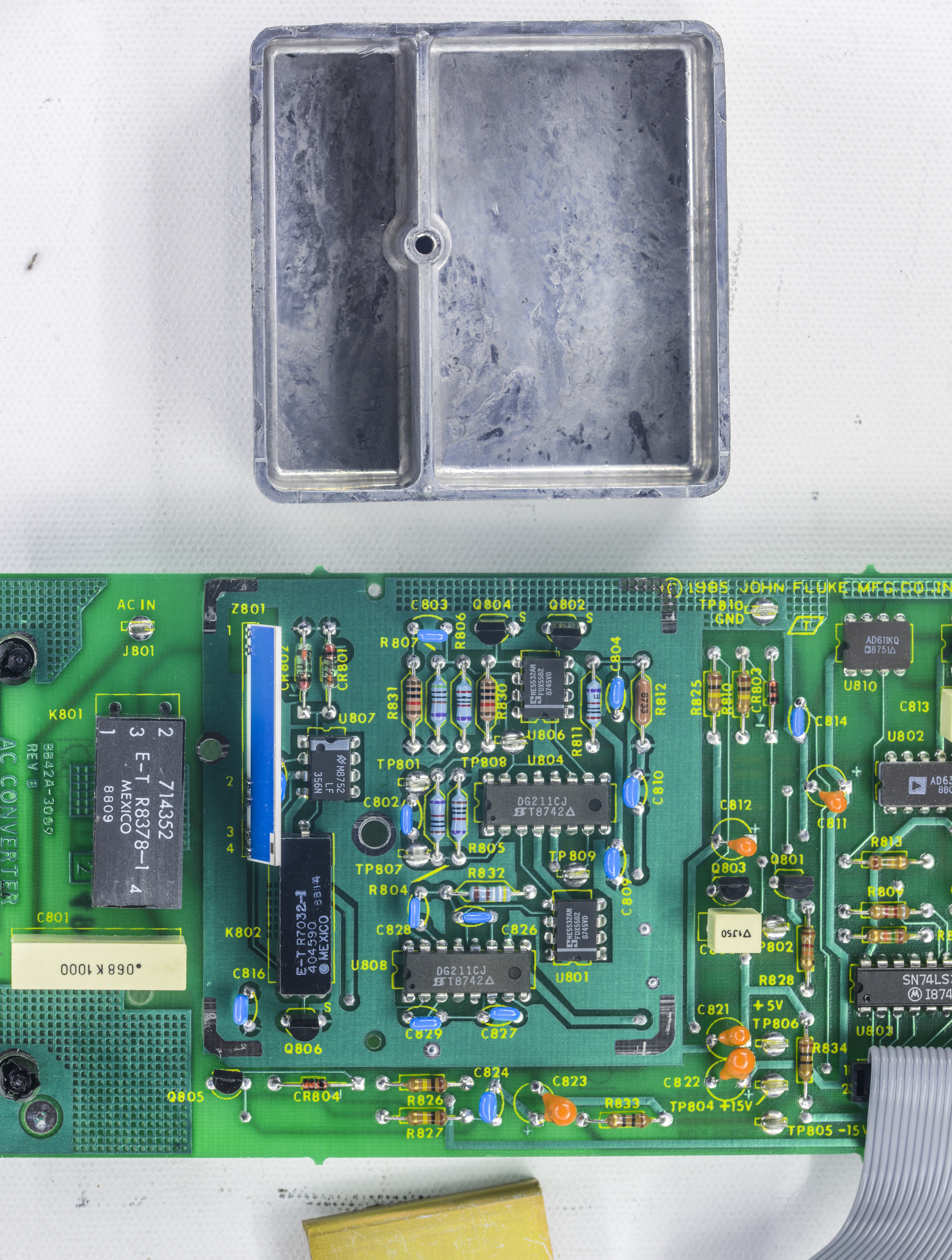
Image 35: AC board shield removed
Removing shield reveal us one more ELECTROL reed relay, ceramic hybrid Z801, few DG211 CMOS switches and three opamps.
NE5532AN opamps are rather popular ones. This whole area on PCB is also filled with copper layer metal to reduce coupling and shield sensitive nodes on higher frequency AC voltages.

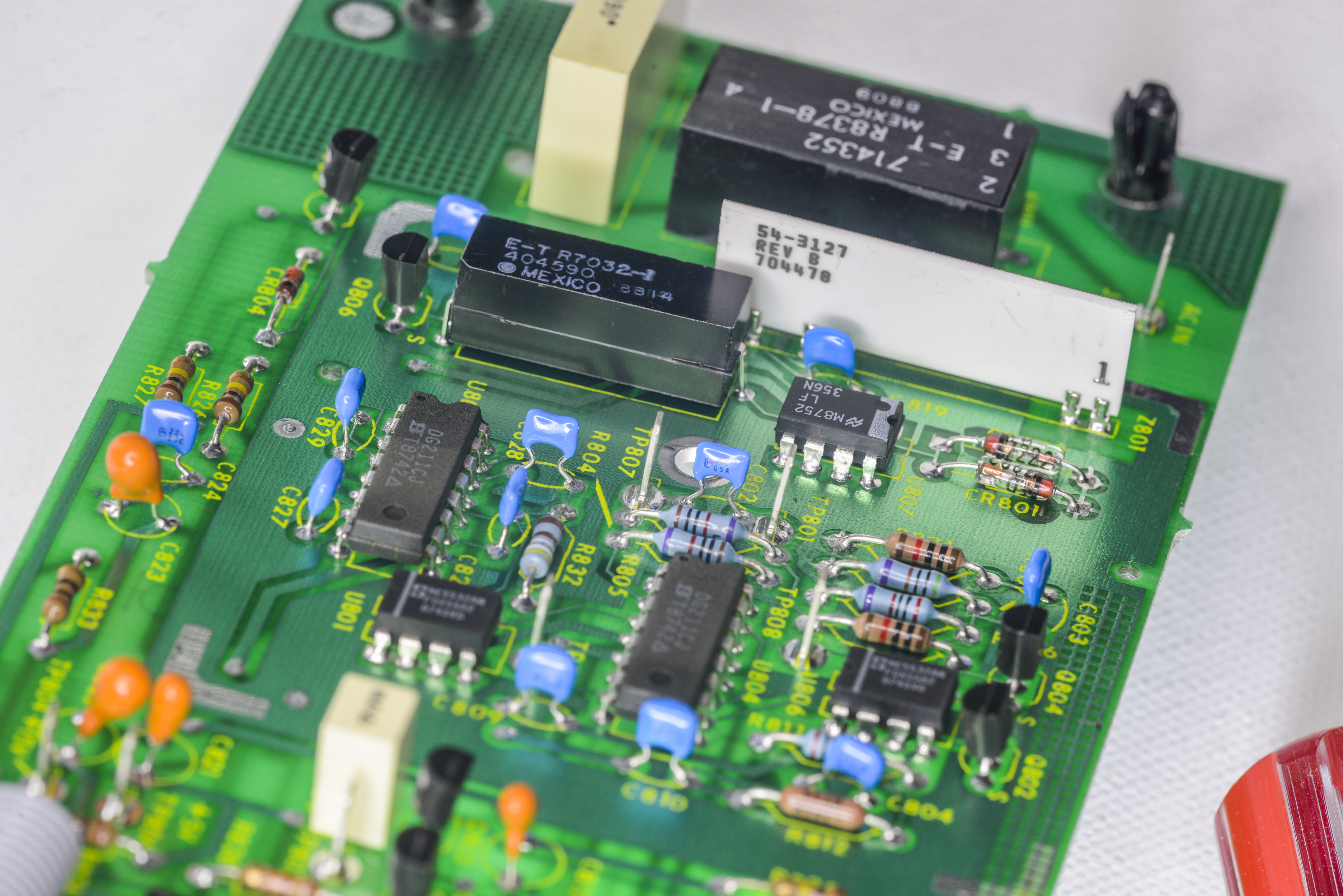
Image 36-37: Other view on shielded parts on AC board
Current measurement also was checked, and both front removable jack and onboard HRC-type fuses are confirmed OK.
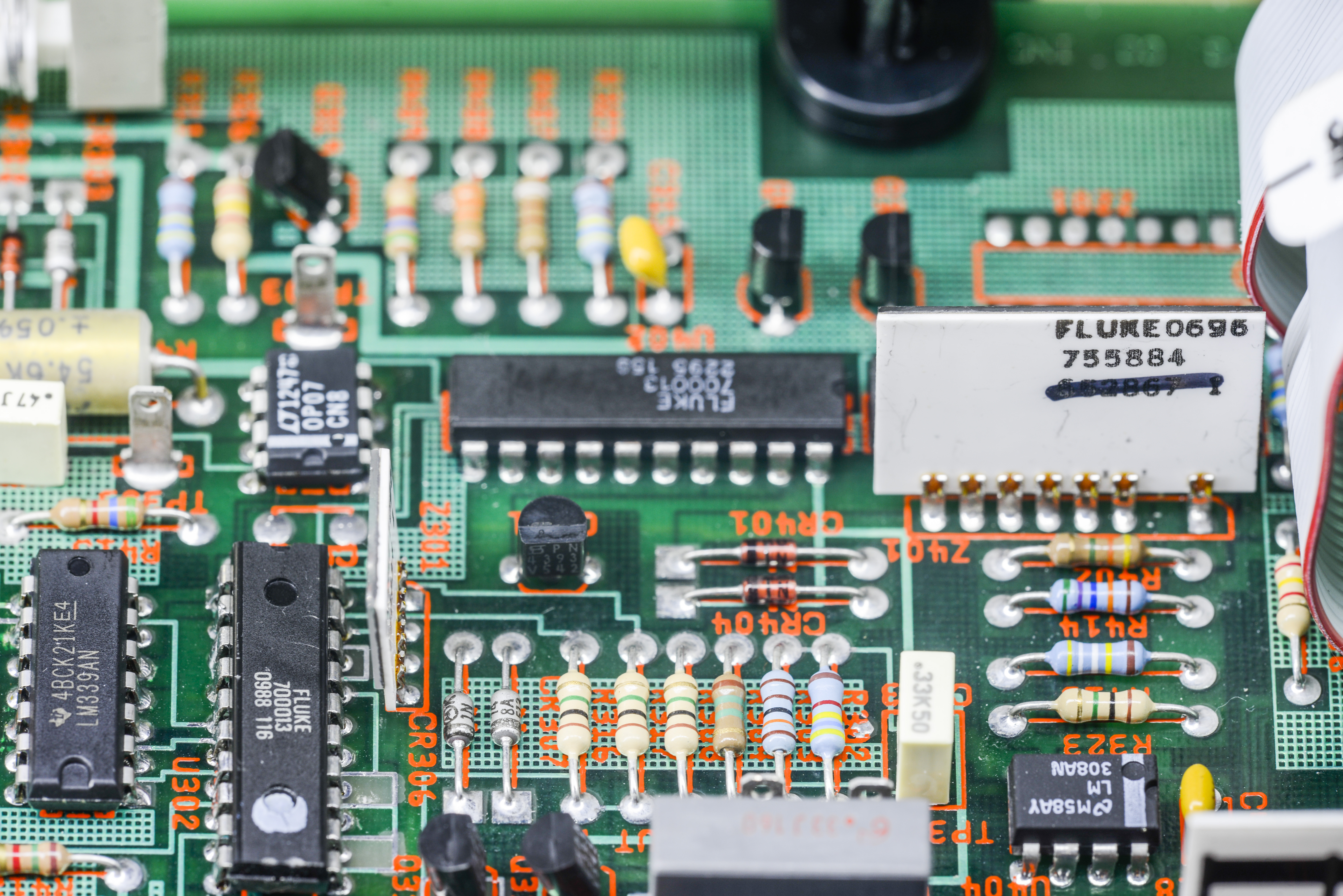

Image 38-39: DAC for A/D conversion operation with its network and current source circuit
You can see new OP07 installed for current source here as well.

Image 40: HRC-type fuse near front/rear input switch. Current shunt also visible nearby.
One last thing – would be good idea to replace input mains filter, as it is famous prone to failures Paffner type. There are multiple cases of these filters exploding in the instruments, filling the room with nasty smells and smokes.
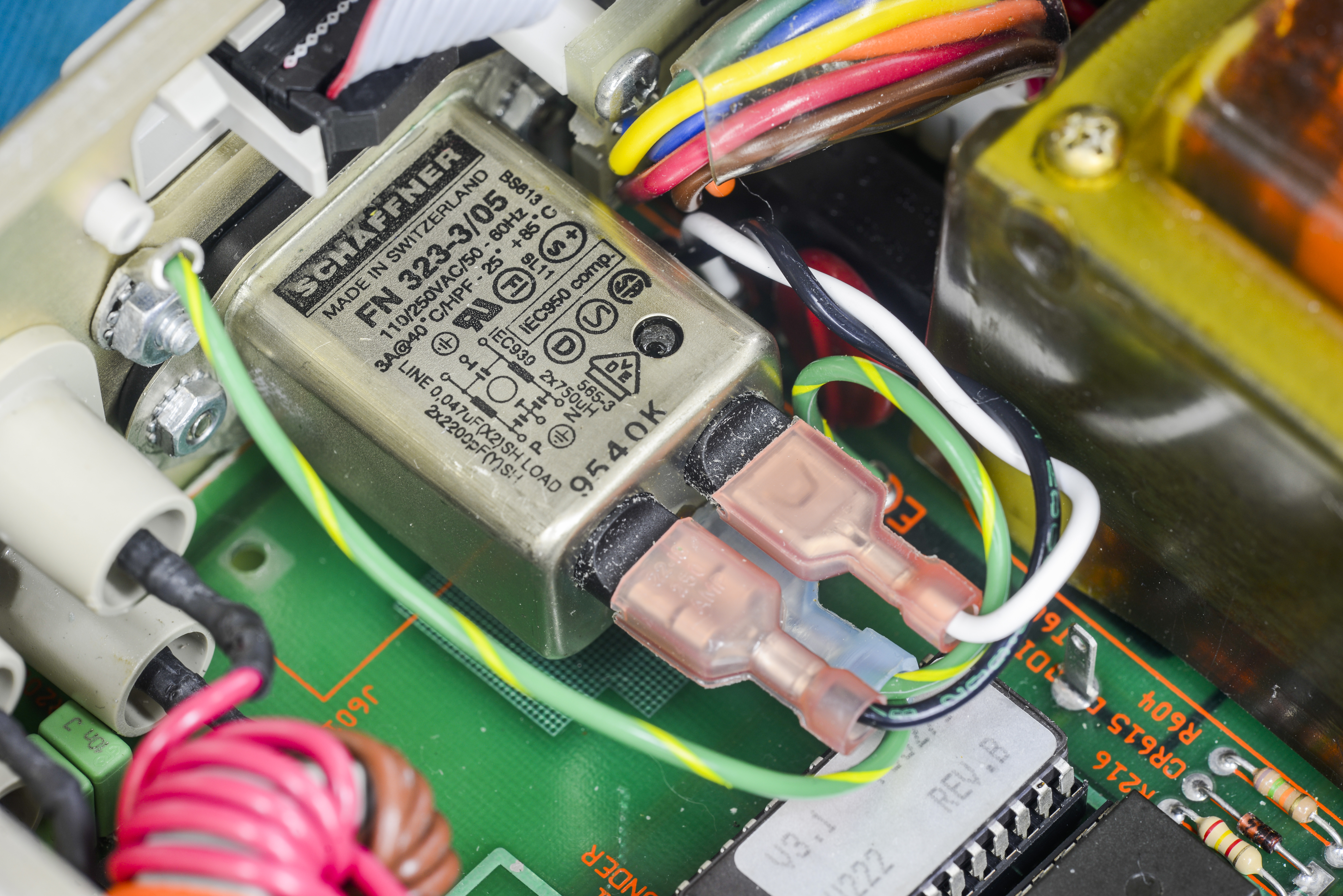
Image 41: Questionable mains power filter
Firmware versions and backups
All meter’s firmware is stored in socketed 4 Kbytes standard ROM, 2732A type. Fluke 8842A using Zilog Z8 MCU which can run on +5V supply and up to 12.5 MHz clock speed. It has just UART, few counter/timers and parallel I/O ports as peripherals.
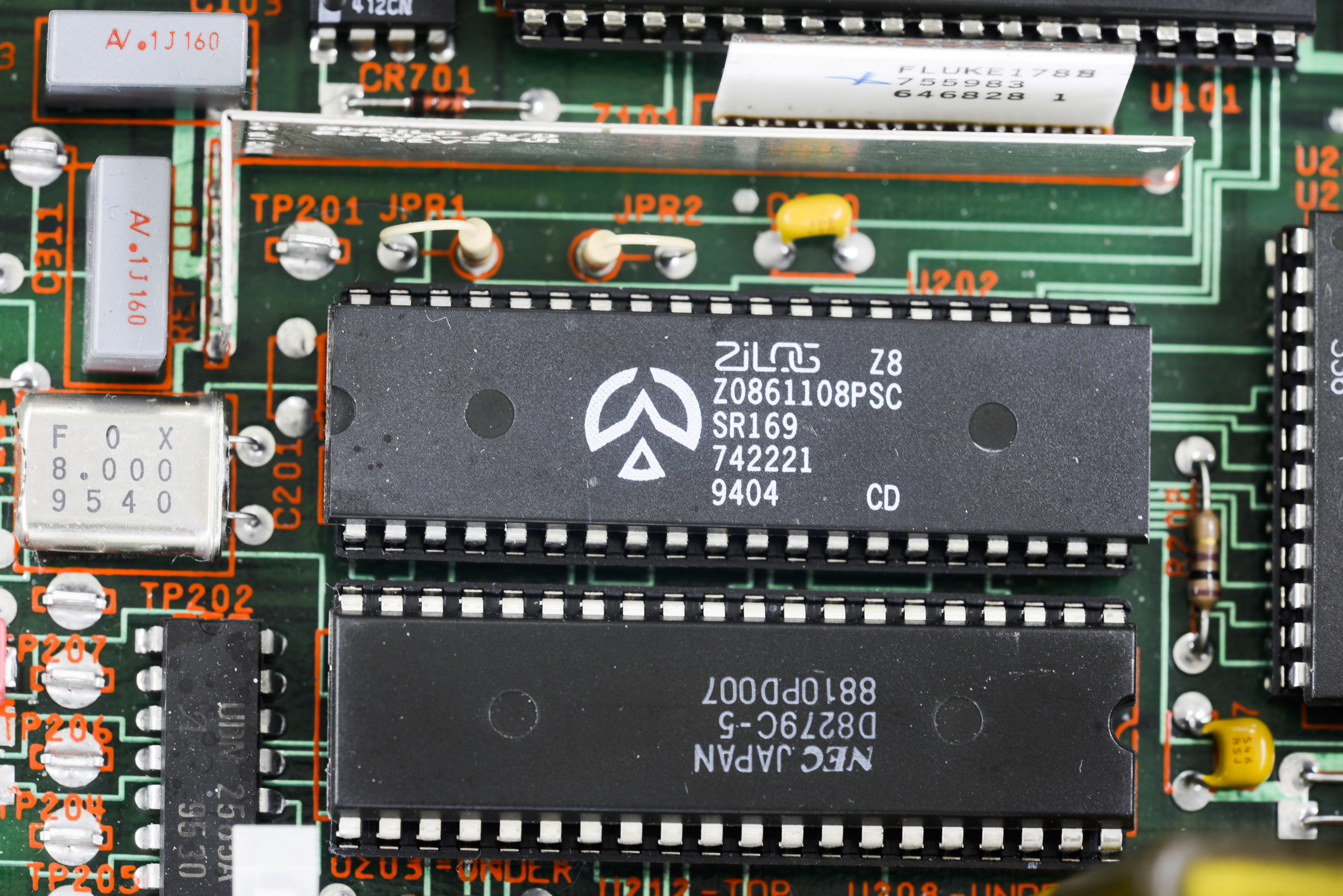
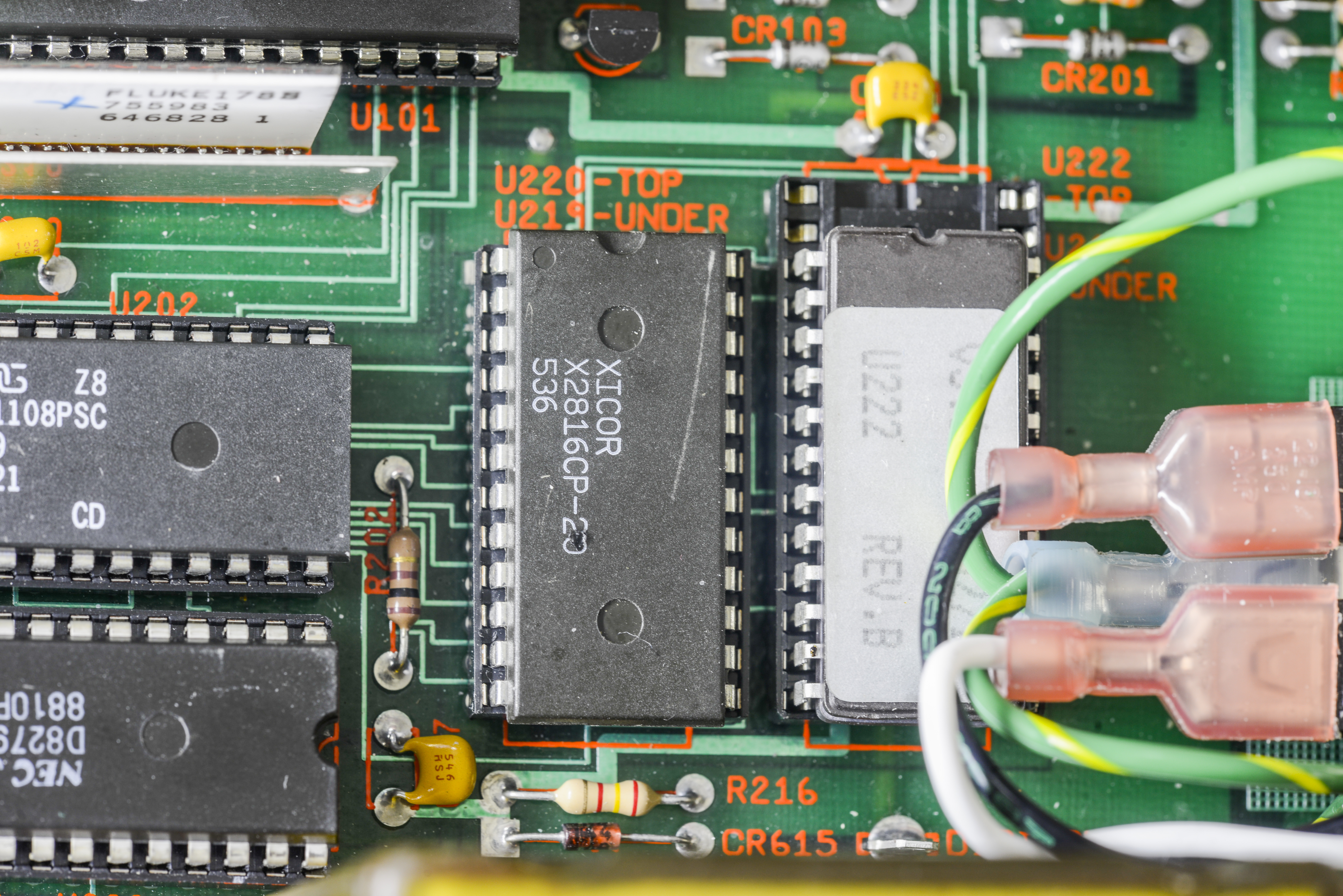
Image 42-43: CPU with external RAM chip in sockets and calibration + firmware ROMs
These ROMs as the 8842A are obsoleted long ago and not available from Fluke.
| Version | Binary | Checksum |
|---|---|---|
| U222 Fluke P/N 765271, version 3.1 | Binary file | 0×00067C4B |
Table 5: Firmware version table and release notes
Credits to Tom Miller (WA3PZI) for the firmware dump.
Calibration and accuracy verification
Just like any other complex electronic measurement equipment this DMM repair project cannot be completed without proper verification of measurement uncertainty and calibration. So to do required performance tests we will follow instruction manual procedures.
Manual recommends use of the 90-day specifications for performance test after calibration, but we can restrict conditions further for better confidence and test against 24-hour specifications. This is possible because no shipping stress or other major disturbances are involved, as meter adjusted, calibrated and tested on the same station. Properly working meter must be able to pass all 24-hour specifications with good margin, to provide confidence of the test result data.
To test performance, and do calibration adjustments we will utilize what is available in lab:
- Fluke 5720A for DCV, ACV, DCI, ACI and Resistance tests
- Keysight 3458A as reference meter for DCV, DCI, ACI and resistance functions.
- Wavetek 4920M as reference meter for ACV function
- Keithley 262 low-thermal divider for 20mV range calibrations
- 4-wire short PCB
- Set of shielded PTFE wires with copper spade lug on MFC side and Pomona low-thermal dual banana jack on meter side.
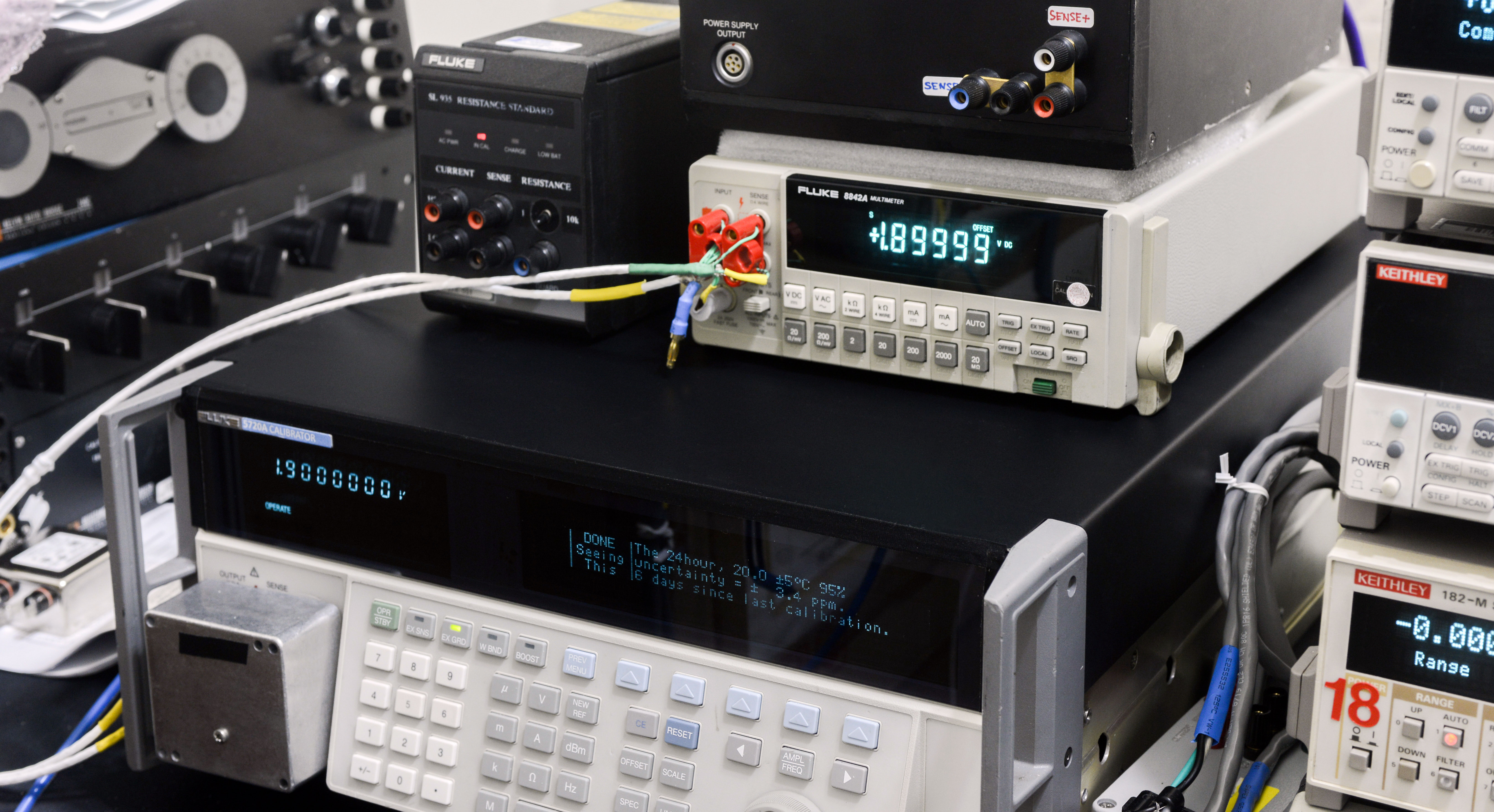
Image 44: Calibration setup used for 8842A verification and adjustment. Keysight 3458A not shown in photo.
Calibrator was artifact calibrated to reference standards just a 5 days ago, but at accuracy levels of 8842A, that is completely unnecessary. Even annual specifications of Fluke 5720A provide good TUR to meet 24 hour specifications of Fluke 8842A, so the calibrator tested just to provide good confidence in results. Ambient temperature was kept at +23 °C ±1 °C.
Calibration adjustment is straight-formward, using instruction manual procedures with slight modifications. Meter asks desired signal, we present it at the input, press STORE and magic happens.

Image 45: Calibration for 19 mV DC. 5720A output 1.9V into Keithley 262 divider, than provide 19.0000 mV for 8842A
DC Voltage test results
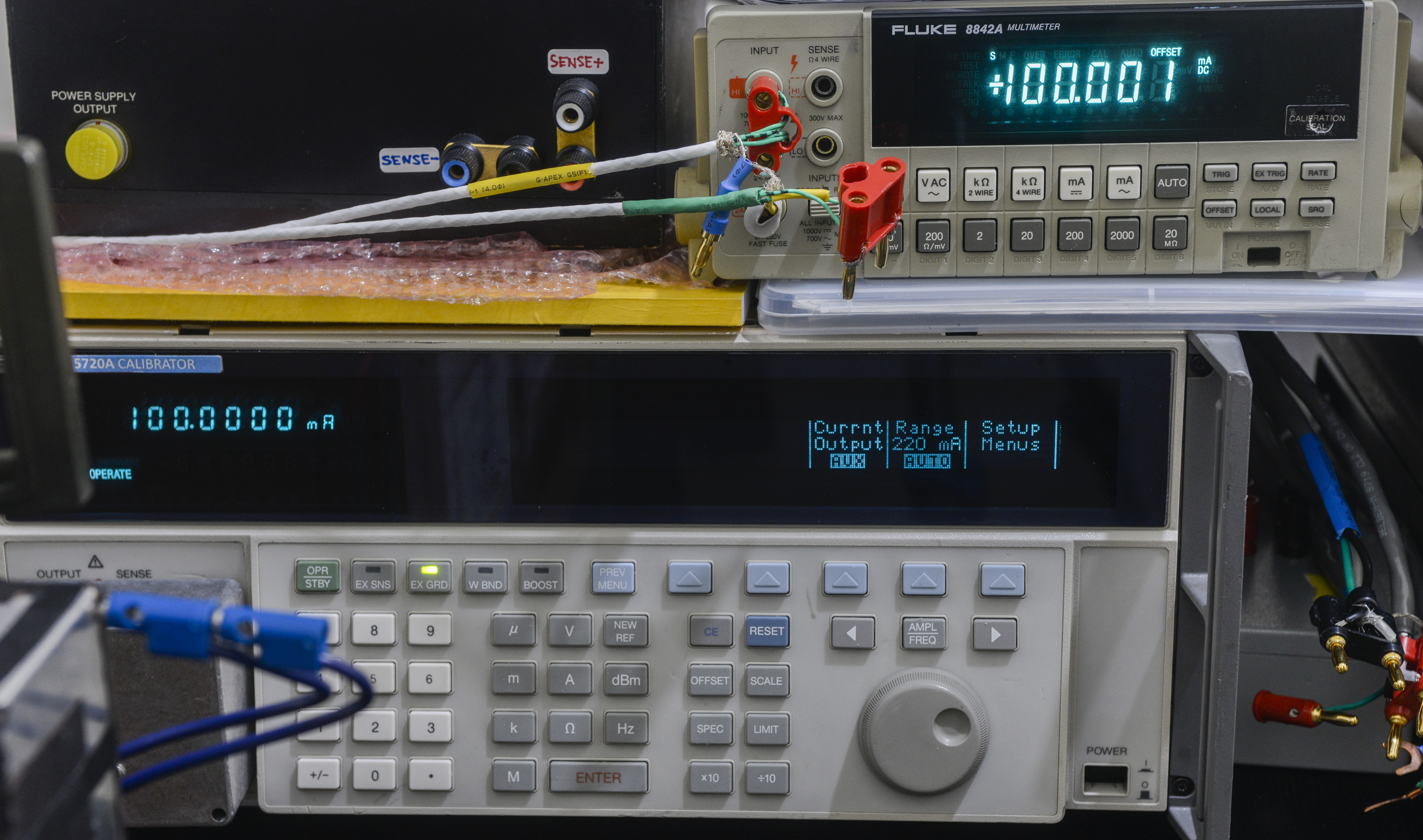
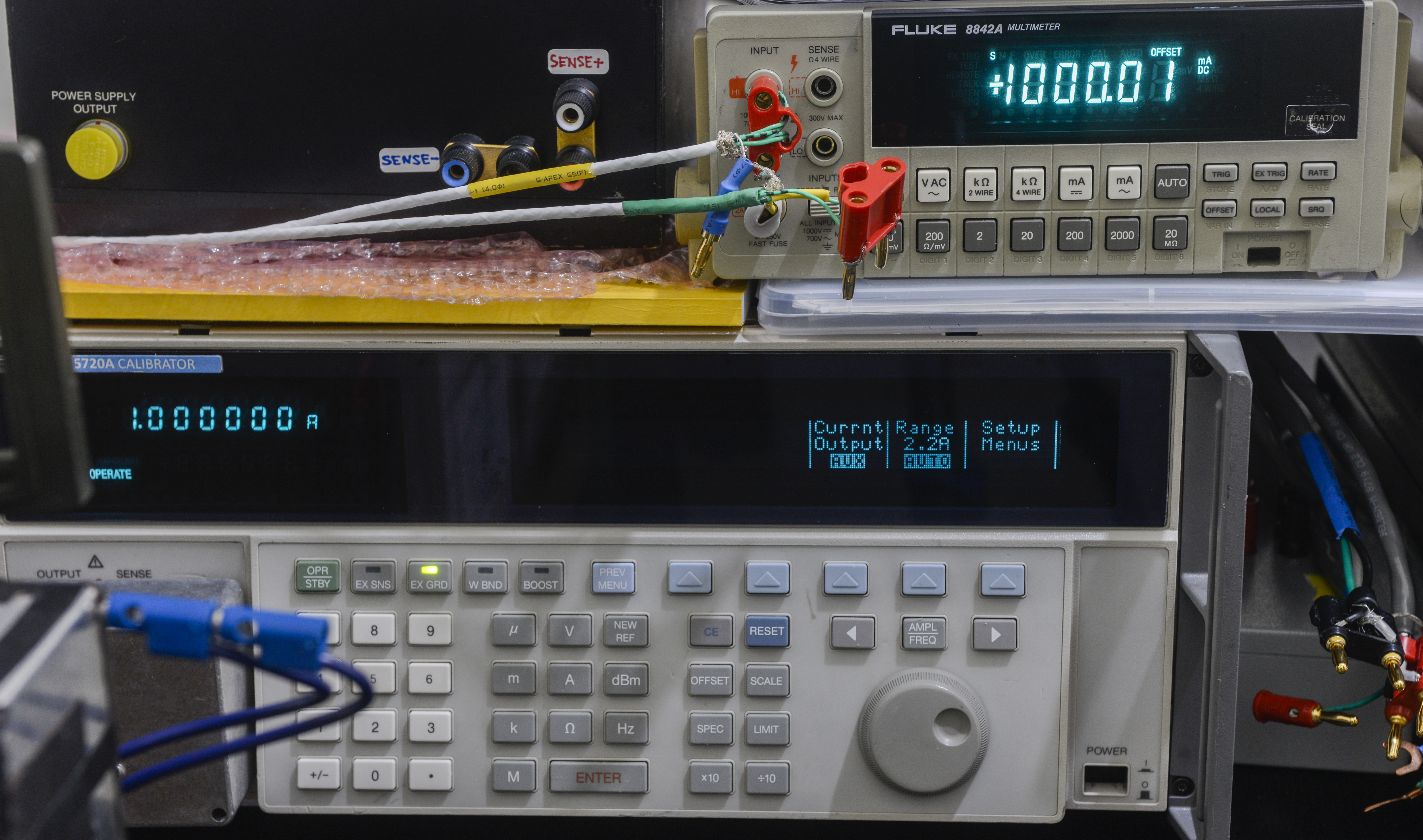

Image 46-48: Current calibration tests
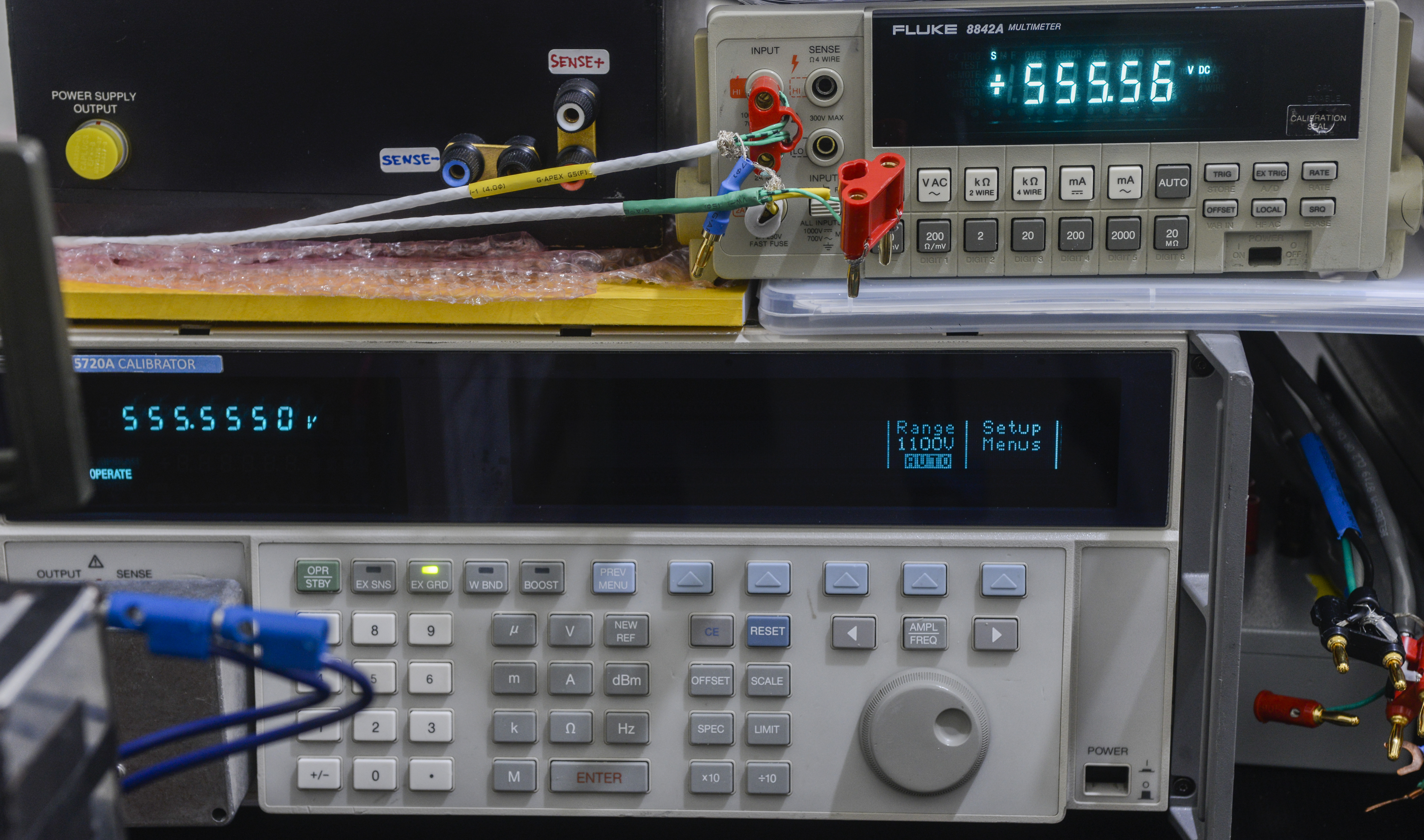


Image 49-51: High voltage DC calibration tests
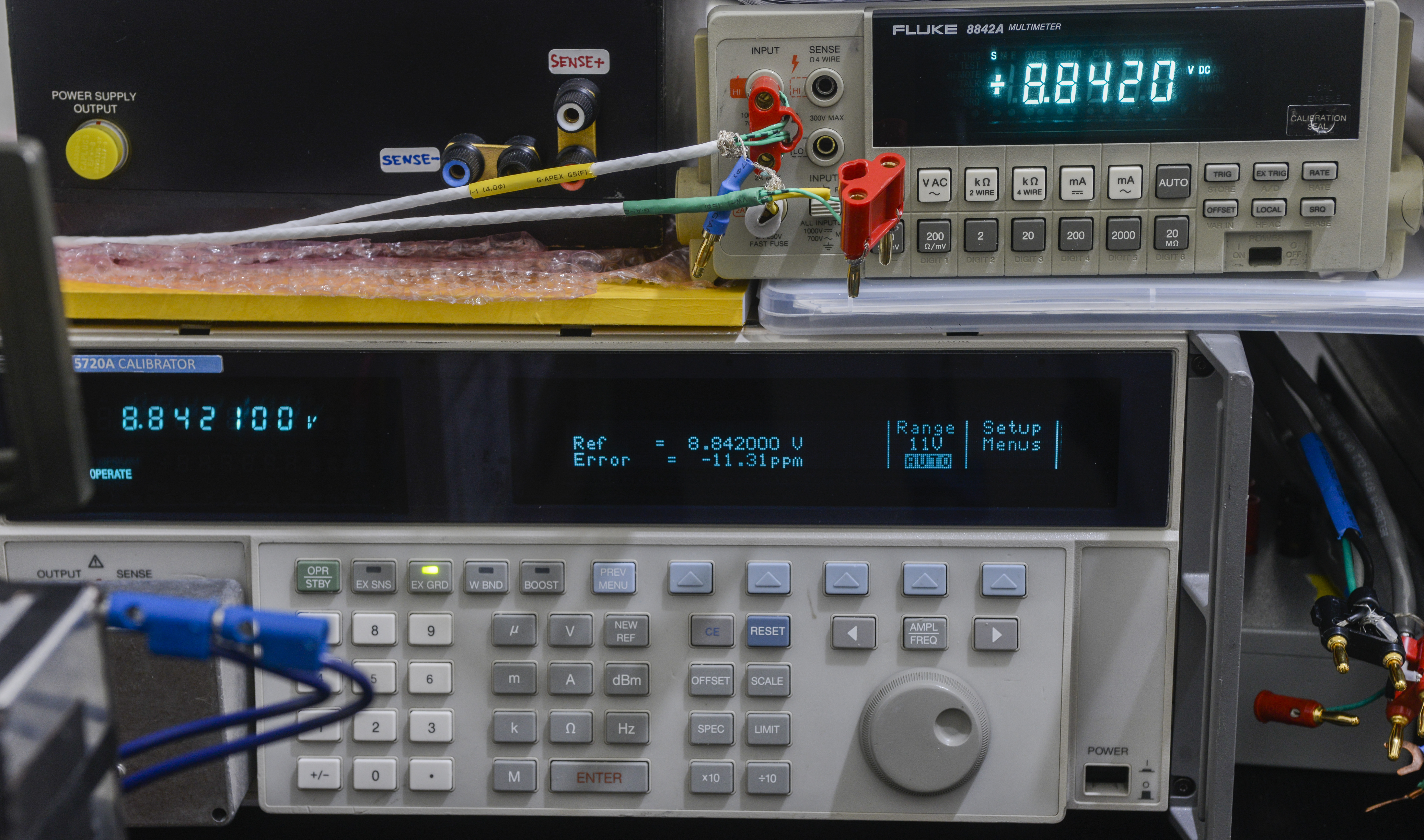
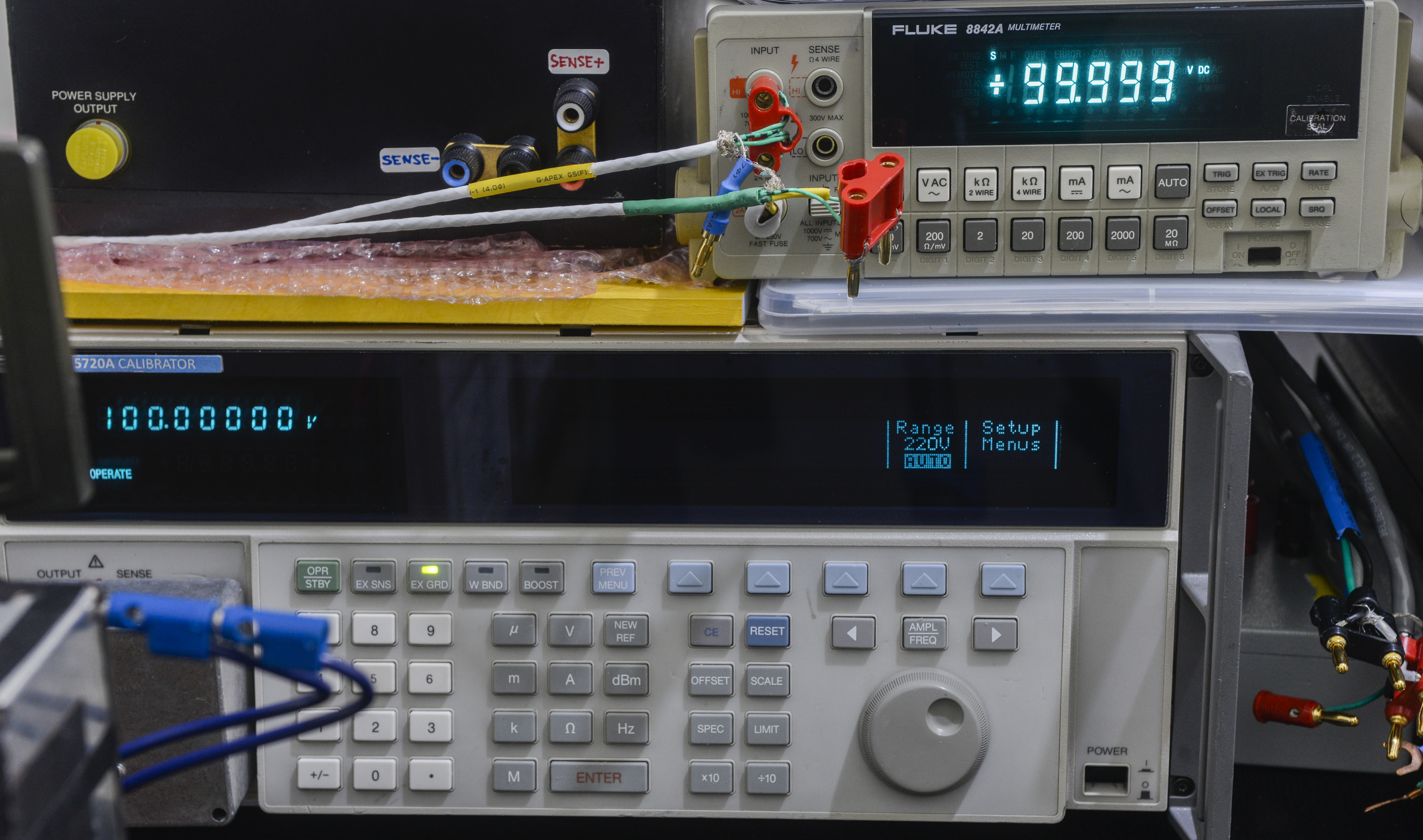
Image 52-53: More DC voltage tests
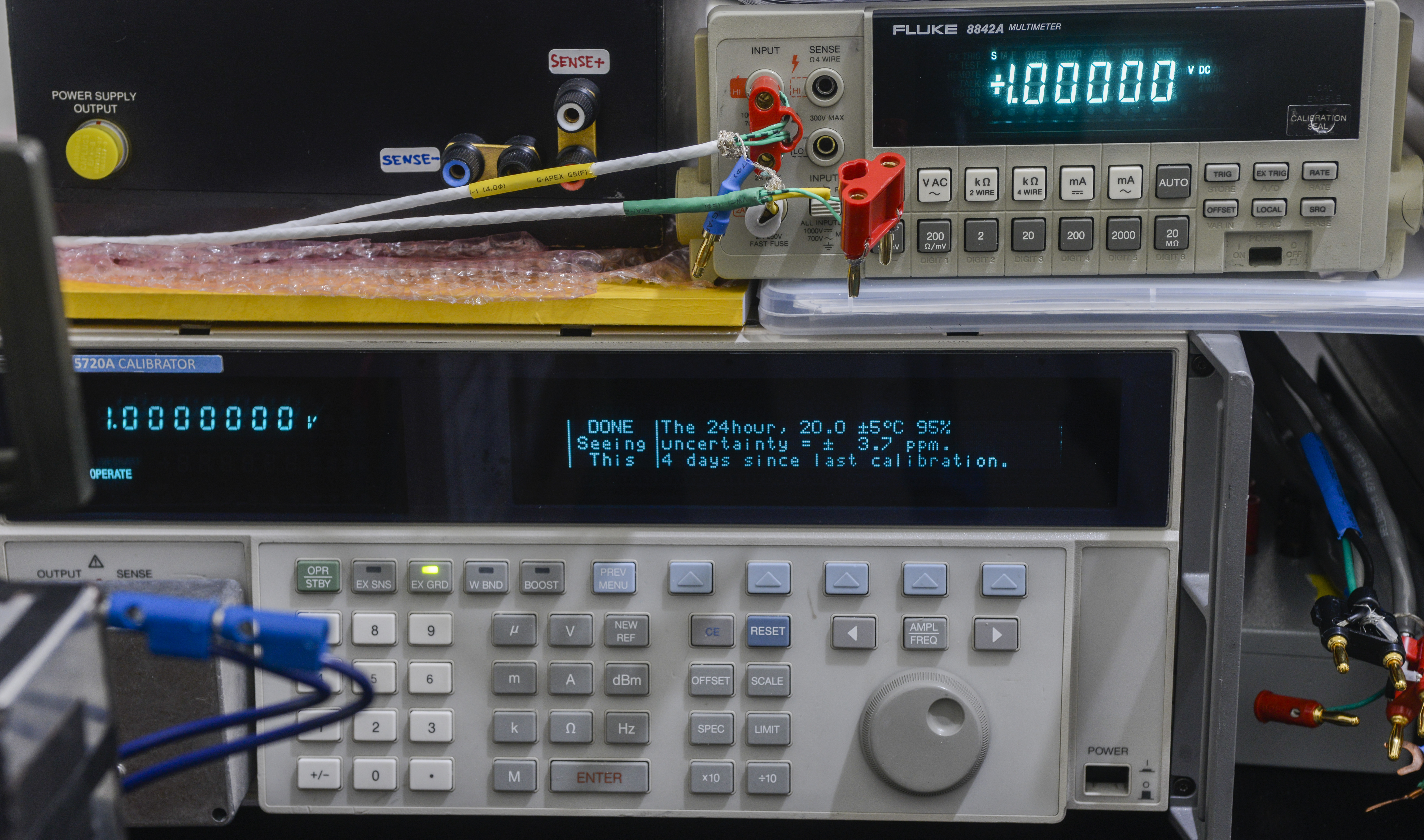
Image 54: +1.0000000 VDC calibration test
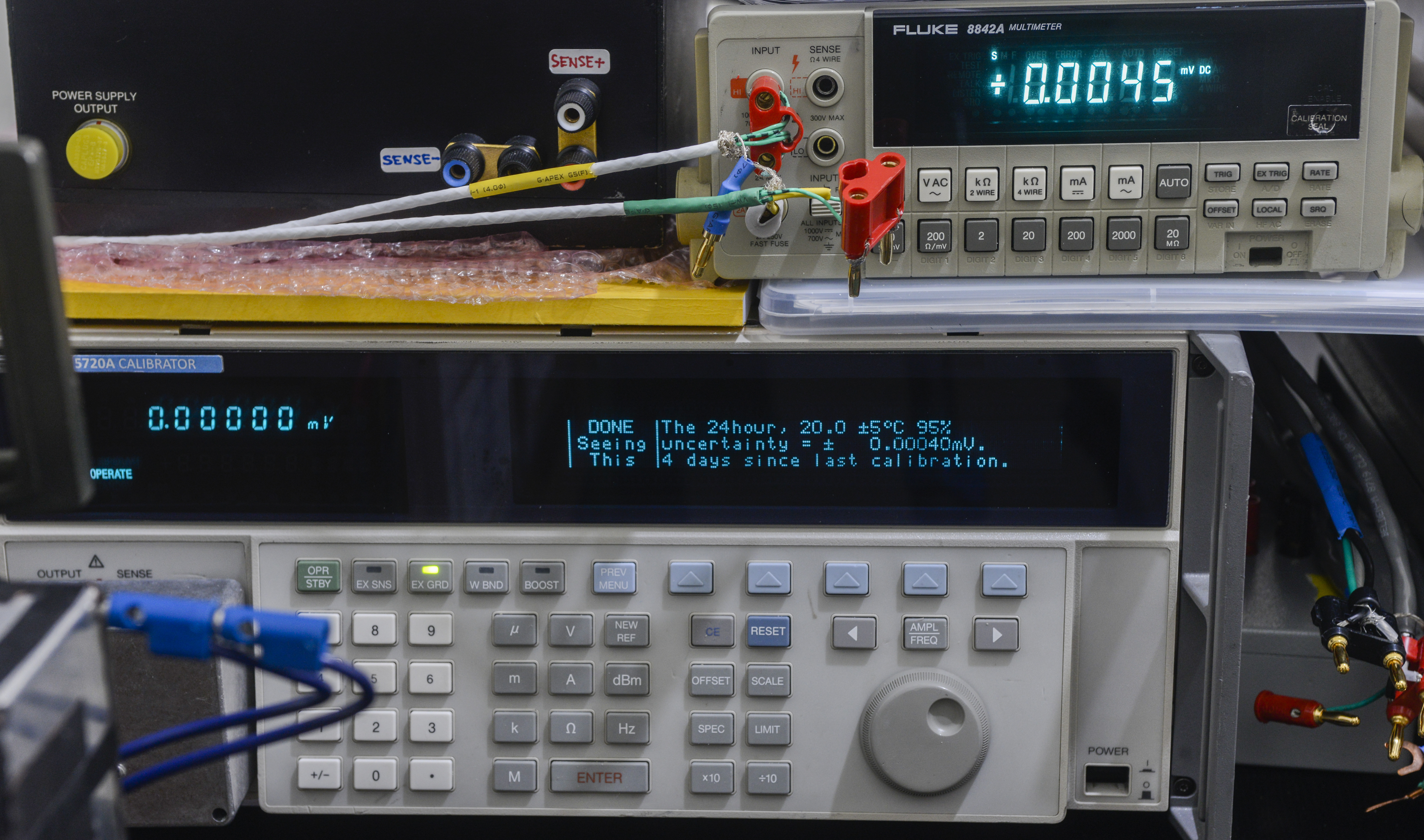
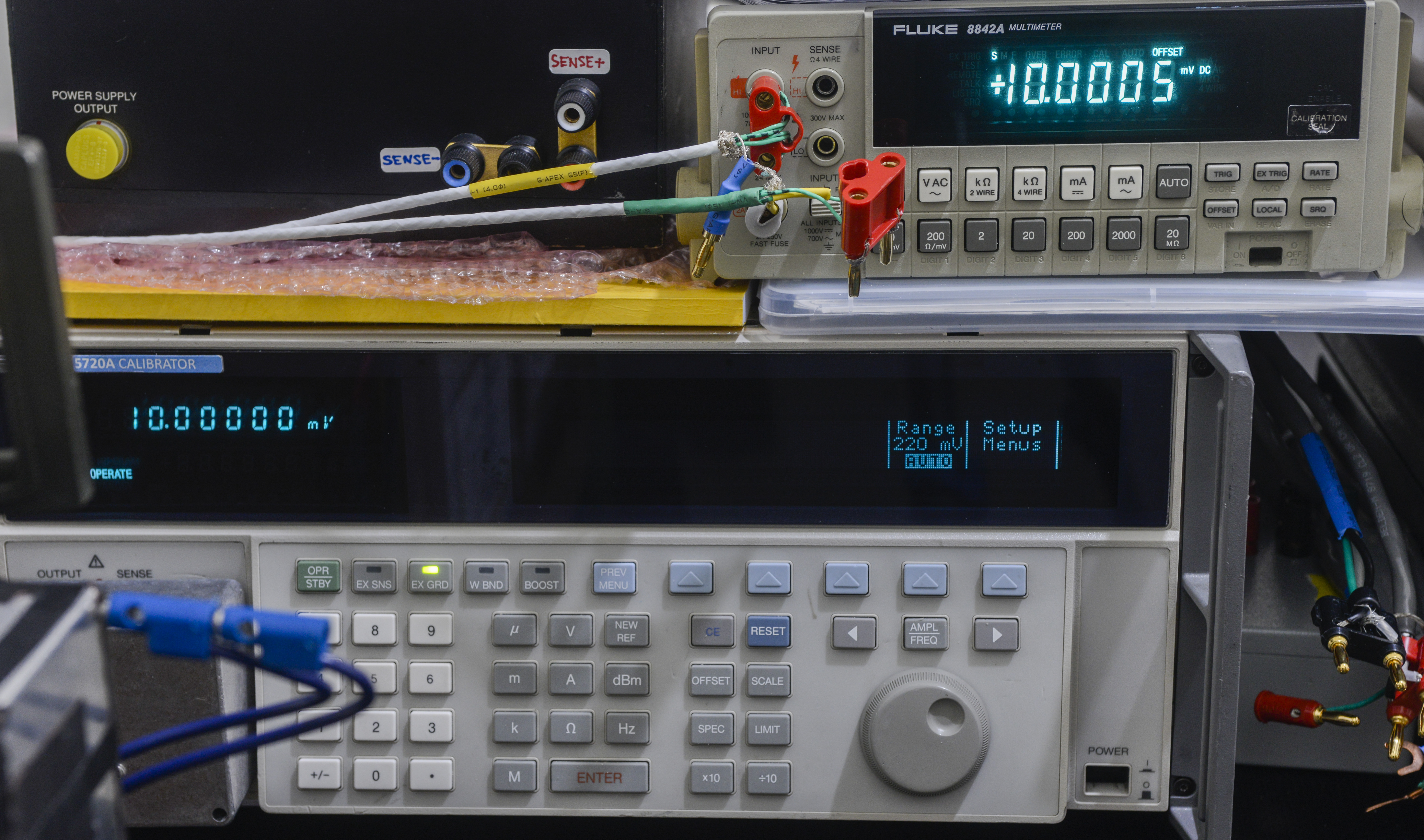

Image 55-57: 20 mVDC range tests


Image 58-59: 20 VDC range tests
TBD..
AC Voltage test results
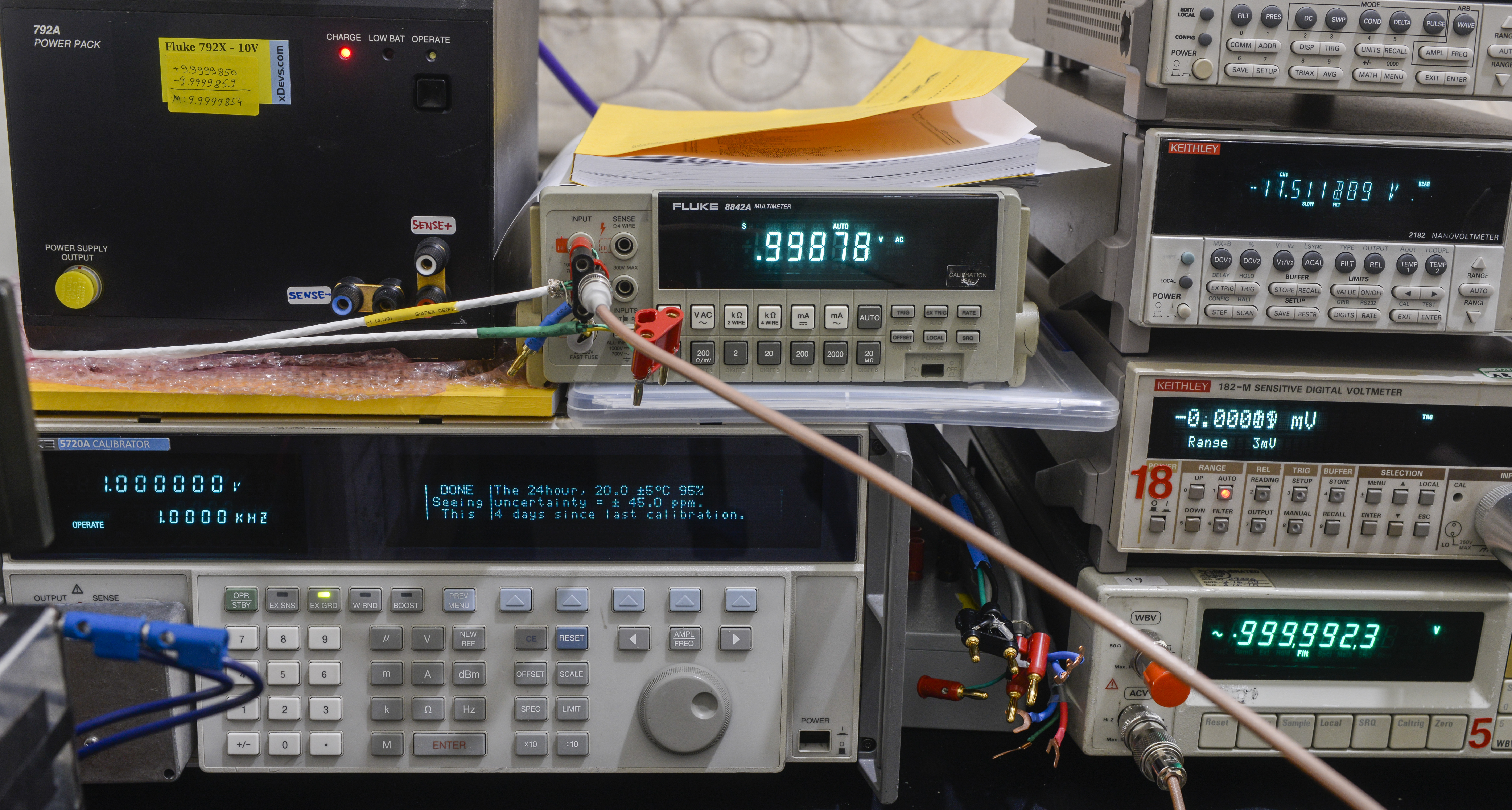
Image 60: 1 VAC, 1 kHz AC voltage calibration tests
TBD..
Resistance test results
| 5720A Output | Measured value | Source uncertainty, ppm | DUT spec, 24 hour | Deviation | Result, %/spec | TUR |
|---|---|---|---|---|---|---|
| 0.999814 | 0.9999 | 32 | 3071 | 86 ppm | 2.8% | 96 |
| 1.899895 | 1.9004 | 25 | 1649 | 266 ppm | 16.1% | 66.0 |
| 10.000356 | 10.0005 | 5 | 370 | 14 ppm | 3.9% | 74 |
| 19.000031 | 19.0001 | 4 | 228 | 4 ppm | 1.6% | 57 |
| 100.00350 | 100.000 | 1.7 | 70 | -35 ppm | -50.0% | 41.2 |
| 189.99846 | 189.997 | 1.7 | 56 | -8 ppm | -13.8% | 32.8 |
| 1000.0124 | 999.99 | 1.7 | 45 | -22 ppm | -49.8% | 26.5 |
| 1900.0270 | 1900.02 | 1.7 | 36 | -4 ppm | -10.4% | 20.9 |
| 9999.803 | 9999.7 | 1.6 | 45 | -10 ppm | -22.9% | 28.1 |
| 18999.415 | 18999.3 | 1.7 | 36 | -6 ppm | -17.0% | 20.9 |
| 99994.87 | 99994 | 2 | 45 | -9 ppm | -19.3% | 22.5 |
| 189989.39 | 189990 | 2 | 36 | 3 ppm | 9.0% | 17.8 |
| 999983.2 | 999850 | 2.5 | 53 | -133 ppm | -251.3% | 21.2 |
| 1899971.8 | 1899970 | 3 | 39 | -1 ppm | -2.4% | 12.9 |
| 9999049 | 9999300 | 10 | 53 | 25 ppm | 47.4% | 5.3 |
| 18998511 | 18998300 | 20 | 39 | -11 ppm | -28.6% | 1.9 |
DC current test results
TBD..
AC current test results
TBD..
Summary
Project cost:
| Item | Cost | Shipping | Supplier |
|---|---|---|---|
| Donor 8842A for parts | $66.6 | $58 | eBay |
| LF356 DIP8 and OP07 opamps | $6.77 | $0 | Digikey |
Table 6: Replacement parts orders
Total restoration cost for this meter: $131 USD.
| Date | Activity | Time spent |
|---|---|---|
| 09/09/2018 | Initial troubleshooting, replacement of parts, debug | 14 hours |
| 09/10/2018 | Calibration, documentation, photos, research manuals | 4 hours |
| 09/12/2018 | Documentation, photos | 5 hours |
Table 7: Timelog summary
Hopefully this repair reveals some light on performance and troubleshooting methods on precision multimeter, like the Fluke 8842A. While it is 28 years old, that still does not mean that it cannot keep up with modern equipment. Use of stable LTFLU-1 reference, hermetic resistor networks, well matched JFETs and high-impedance 20V range provide real performance beyond specified 5½-digits resolution over long period of time. We would have more confidence in old but calibrated 8842A, than in some modern entry-level 6½-digit meters.
Also no BGA-packaged FPGAs or Linux computers inside this meter, so it is relatively easy to repair, given that custom Fluke resistors and unobtanium JFET/Fluke ASICs are okay. Even broken meters, these can be bought for under $100 USD, making it nice addition to the electronics hobbyist bench. If one is lucky to get IEEE-488 GPIB option card, then with help of linux-gpib and Raspberry Pi + python scripts this meter can also have all advanced math functions, graph plotting and statistic analysis features like fancy expensive Keithley DMM7510 or Keysight 34470A at 1/100th of the cost :)
Discussion about this article and related stuff is welcome in comment section or at our own IRC chat server: irc.xdevs.com (standard port 6667, channel: #xDevs.com). Web-interface for access mirrored on this page.
Projects like this are born from passion and a desire to share how things work. Education is the foundation of a healthy society - especially important in today's volatile world. xDevs began as a personal project notepad in Kherson, Ukraine back in 2008 and has grown with support of passionate readers just like you. There are no (and never will be) any ads, sponsors or shareholders behind xDevs.com, just a commitment to inspire and help learning. If you are in a position to help others like us, please consider supporting xDevs.com’s home-country Ukraine in its defense of freedom to speak, freedom to live in peace and freedom to choose their way. You can use official site to support Ukraine – United24 or Help99. Every cent counts.
Modified: Oct. 28, 2024, 7:47 p.m.