Contents
- Intro
- Disclaimer
- Manuals
- xDevs service methodology for old equipment
- What is the Ref-Amp?
- Refurbishment of S/N 3675006 732A unit
- Parts replacements
- 732A Chassis
- Reassembly and first power on smoke test
- Performance tests
- Design and construction for some other Fluke 732A
- Design and construction for Fluke 732B
- Design and construction for Fluke 732C
- Modifications for Model 732A
- Temperature coefficient performance
- Temperature coefficient results with oven
- Comparisons and long-term drift data
- Summary & Conclusion
![]()
![]()
![]()
![]()
![]()
![]()
![]()
![]()
![]()
![]()
![]()
![]()
![]()
![]()
![]()
![]()
![]()
![]()
![]()
![]()
![]()
![]()
![]()
![]()
![]()
![]()
![]()
![]()
![]()
![]()
![]()
![]()
![]()
![]()
![]()
Intro
In this article we will look into series of voltage standards from Fluke, under model names 732A, 732B and latest 732C. Old and legacy but still very good Fluke 732A DC Voltage standard will be serviced and tested. We have multiple units so inter-comparisons will be performed to obtain relative drift rate and performance across multiple units.
xDevs zener voltage array already using two of such Fluke 732A standards to maintain the “lab volt” along with other LTZ1000A-based standards. These are often well aged and capable to provide stability better than 0.5 µV/V per year, especially when constantly powered and permanently fixed in the laboratory without any additional disturbances.
There is also exclusive online teardown of latest generation Fluke 732C with detailed photos of internal hardware including ovenized refamp module.
Disclaimer
Redistribution and use of this article or any images or files referenced in it, in source and binary forms, with or without modification, are permitted provided that the following conditions are met:
- Redistributions of article must retain the above copyright notice, this list of conditions, link to this page (https://xdevs.com/fix/f732a/) and the following disclaimer.
- Redistributions of files in binary form must reproduce the above copyright notice, this list of conditions, link to this page (https://xdevs.com/fix/f732a/), and the following disclaimer in the documentation and/or other materials provided with the distribution, for example Readme file.
All information posted here is hosted just for education purposes and provided AS IS. In no event shall the author, xDevs.com site, or Fluke or any other 3rd party be liable for any special, direct, indirect, or consequential damages or any damages whatsoever resulting from loss of use, data or profits, whether in an action of contract, negligence or other tortuous action, arising out of or in connection with the use or performance of information published here.
If you willing to contribute or have interesting documentation to share regarding pressure measurements or metrology and electronics in general, you can do so by following these simple instructions.
Manuals and service information
Fluke 732A DC voltage standard system instruction manual
Fluke 732B/734A DC voltage standard instruction manual
Fluke 732A errata Issue 3 1985 for modifications and changes
Understanding DC standard specifications
Operator manual for Fluke 732C/734C, August 2018
Fluke 732C/734C specifications
Fluke 732C/734C safety information
732C/734C battary safety datasheet, MSDS
Fluke 7001 series DC voltage standard system instruction manual
Comparison for known specifications of production voltage standards:
| Specification | Fluke 732A | Fluke 732B | Fluke 732C | Fluke 734A or 734C | Datron 4910 | Fluke 5730A calibrator |
|---|---|---|---|---|---|---|
| Output voltage, DC | 1V, 1.018V, 10V | 1.018V, 10V | 0.1V, 1V, 10V | 4 × 732B or 732C | 4 × 1.018V, 10V | up to 1100V |
| Stability (1y, 10V) | ±6 ppm | ±2 ppm | <±2 ppm | ±1 ppm | ±2 ppm | |
| Stability (30 day, 10V) | ±0.5 ppm | ±0.3 ppm | <±0.3 ppm | ±1 ppm | ±2 ppm | |
| Temperature coefficient, ppm | ±0.05 ppm/°C | ±0.04 ppm | ±0.04 ppm | <±0.1 ppm/°C | ±3 ppm max (18-28°C) | |
| Adjustment range | 50µV, <0.05ppm | None | Programmable 7½-digits | |||
| Reference design solution | Motorola SZA263 | LTFLU-1 | up to 4 x Linear LTZ1000ACH | 2 x LTFLU-1 | ||
| Max load current | 12 mA | 200 mA | 10 mA | 418 mA | ||
| Output noise | <1 µVRMS, 0.1-10Hz | <0.6 µVRMS, 0.1-10Hz | 3.5 µVRMS, 0.1-10Hz | |||
| Construction type | Rugged half-rack module | Rugged ¼-rack module | Full-width 19” rack frame | Rugged half-rack module | Full-size rackmount | |
| Active thermal compensation | Yes, +45° C oven assembly | LTZ1000 internal oven | Yes, multiple ovens | |||
| Temperature sensor for monitoring | Yes | No | ||||
| Operation range, ambient | +0…+40 °C | 0…+50 °C | ||||
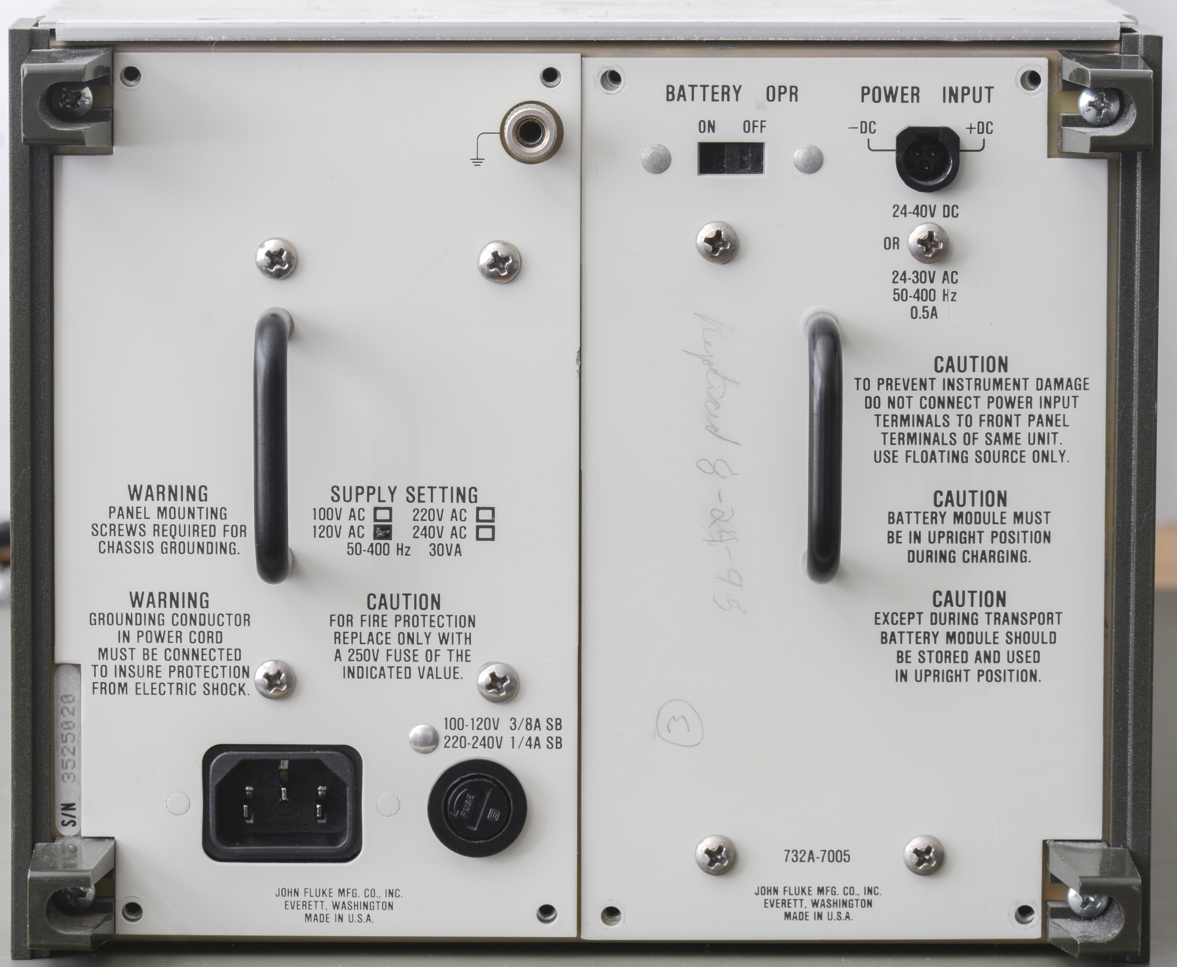
| Power requirements | 100,120,220,240VAC or 24-40VDC | 100,120,220,240VAC or 12VDC | 250W mains powered | |||
| Backup/offline power supply | Internal ±12V Battery bank, 12 hours life | Internal ±12V Battery bank, 72 hours life | None | |||
| Dimensions, weight | 191 × 221 × 603 mm, 12.3kg | 254 × 206 × 311 mm, 4.8kg | 86 × 105 × 127 mm, 730g | |||
| MSRP | ~$2k USD [EOL] | $9k USD [EOL] | $15k USD | $60k+ USD | $10k+ USD [EOL] | $90k+ USD |
Fluke also provided special order service to replace 1.018 VDC output to 1.000 VDC on their 732B units.
Service methodology for old equipment
As typical for most of the test equipment older than 20 years strategy is to replace aged parts with modern fresh stuff and address any prone to failure components. I consider old tantalum and electrolytic capacitors as consumable parts and replace them outright without testing or measurements of their condition.
This blind replacement process need to be done even if they “look good” and not oozing electrolyte all over yet (like in old 30 year Keithley 2001 or HP 4263B). I often read online that replacing perfectly good parts is pointless and waste but real life proved this idea faulty many times, even recently with tantalum cap catching fire. Great way to risk expensive lab burning down, since many of such equipment is left unattended for days, weeks and months. In worst case even if one replaced truly good cap all we lost is spending some gold and time on caps and gained a peace of mind.
Another common component type that is replaced outright – carbon composite resistors. This type resistors age badly over the years and not uncommon to drift 20%-40% or even more out of their initial factory tolerance. Many circuits might still work with such gross deviation but others would not, so why take the chances? Fluke 732A has plenty of CC resistors and all of them we will be replacing too.
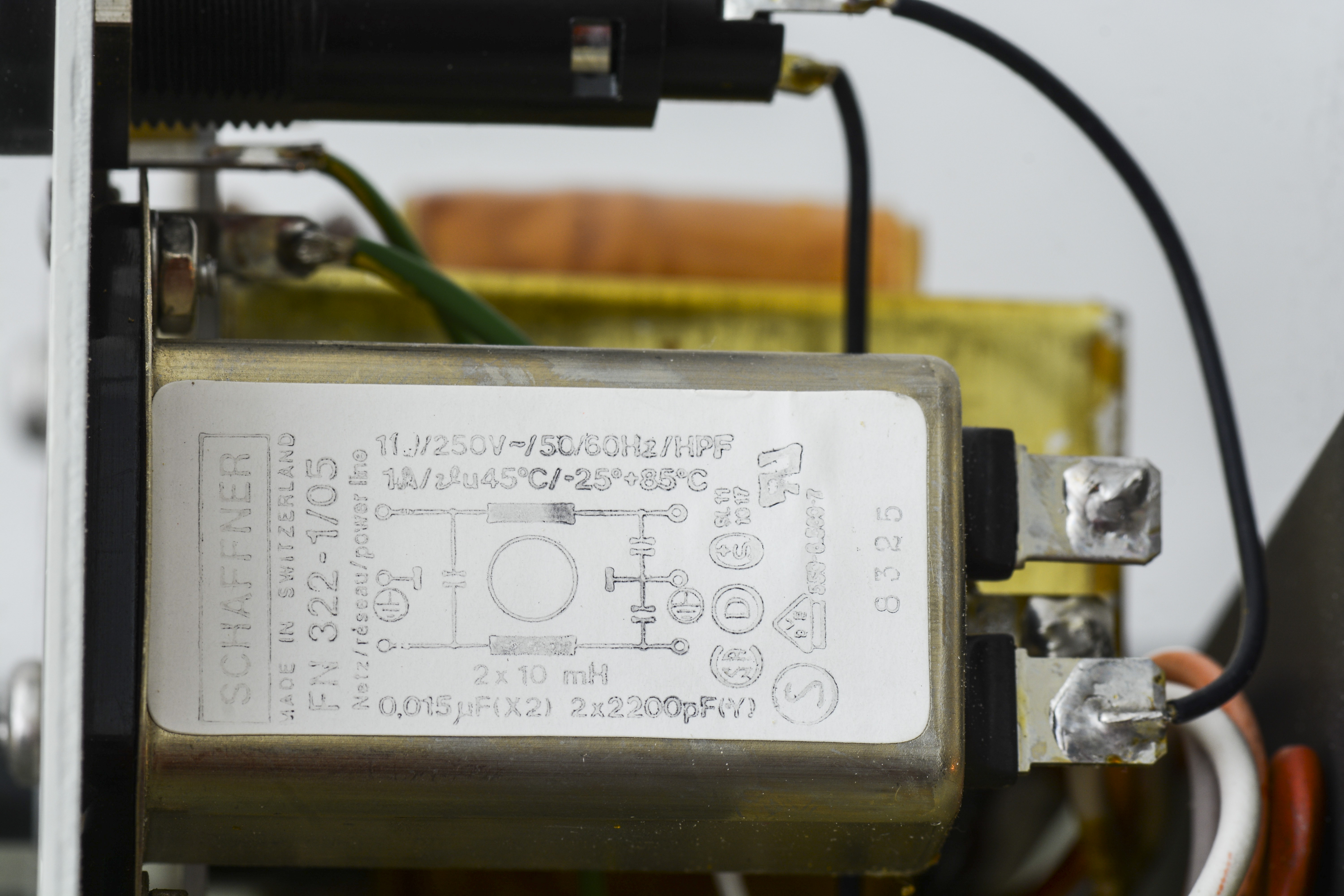
Mains filter is also common failure point, especially for countries with proper 230-240 V mains line voltage. There were many HP3458A and HP3245A and other instruments with RIFA caps that blew up and filled labs with nasty smell of burning electronics for days, so why take chances for $20 part?
With these ideas in mind we can open up today 732A and start swapping parts. In case of 732A I also like to replace power transistors with modern replacement stuff, which runs bit cooler. :)
Not the best idea to start replacing parts randomly in test equipment and knowledge of circuit operation is important here. We have years of experience fixing and working with metrology-grade instruments and know that it’s safe to do swaps for Fluke 732A as described above.
Highly sensitive instruments and circuits however might not be as robust and learn the instrument first before doing blind parts replacements. Using proper soldering equipment and tools is also paramount to avoid adding damage or zapping unobtanium JFETs with electrostatic discharges. Many times in the past xDevs acquired equipment ruined by previous “repair” attempts, delaminated overheated circuit boards and bad components installed instead of proven good part.
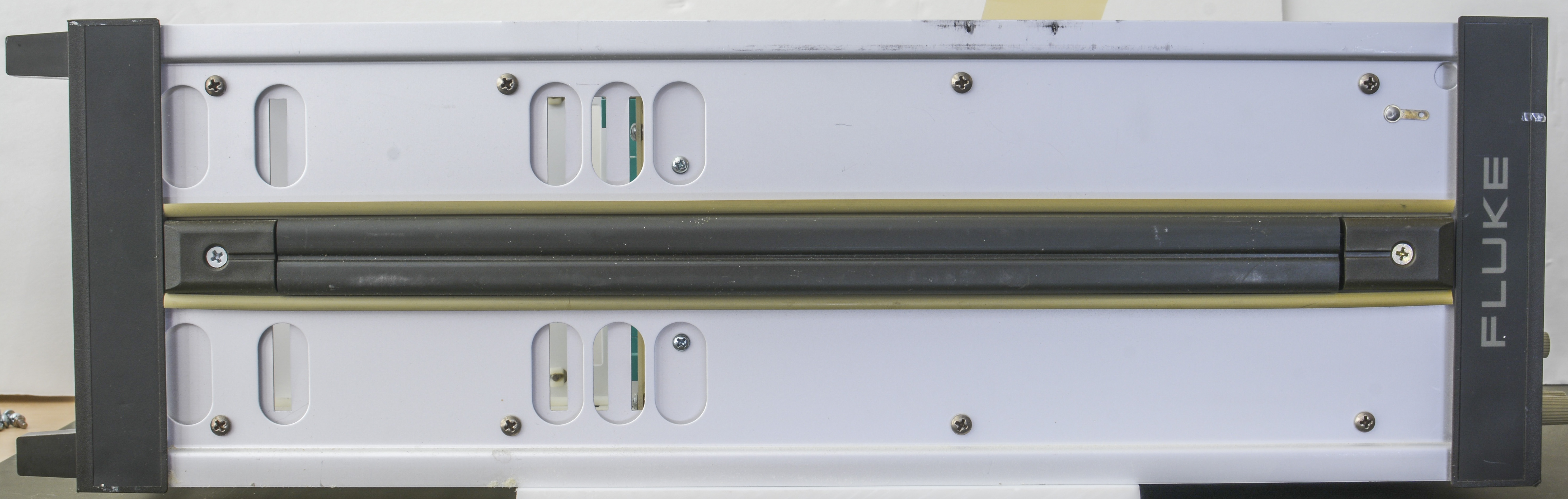
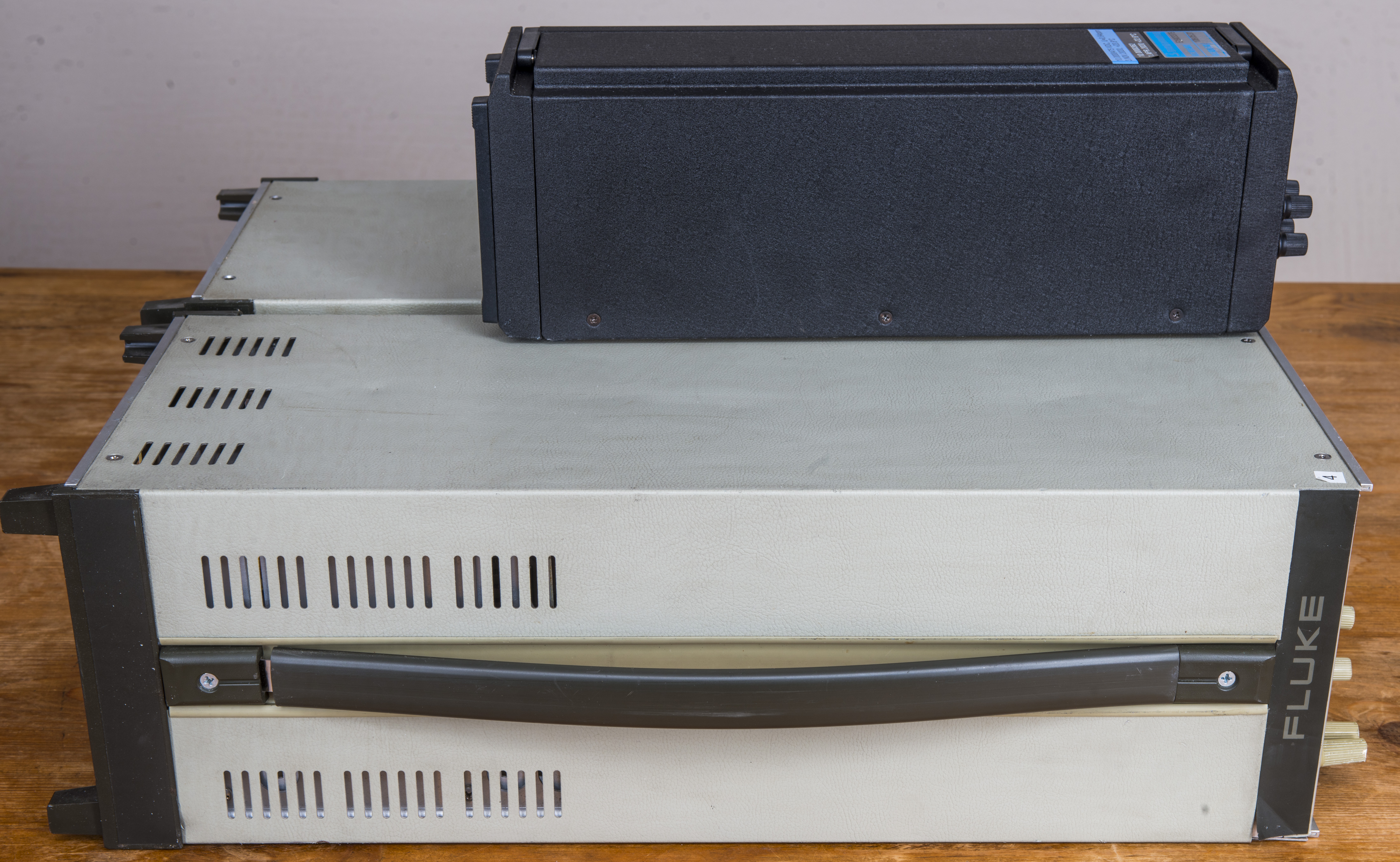
Model 732A is rather bulky beast that demands deep bench or rackmount installation. All 732 zener standards based around REFAMP zener core.
What is the Ref-Amp?
Ref-Amp consists of an NPN transistor in series with a zener diode. When biased properly, the combination has a extremely low temperature coefficient. The reference voltage that the can vary from +6.5 VDC to +7 VDC, depends on actual production bath. Also since both zener and transistor are located on same substrate and enclosed in hermetic package, they are tightly thermally coupled and protected from ambient humidity. This allows to improve stability over long time spans.
There are two well-known examples of this device family, Ref-Amps used by Fluke in high-end instrumentation equipment. These are Motorola SZA263 and Linear LTFLU-1H/LTFLU-1AH.
The Motorola SZA263 is a “Ref-Amp” that was made by Motorola, and later discontinued after getting out of high-volume semiconductor business. This forced Fluke to find a partner to design a replacement for the obsolete SZA263, as Motorola would not sell the design files and masks of original design. Linear Technology was happy to help big customer like Fluke with the design, and that’s how LTFLU-1AH Ref-Amp emerged. It’s pin-2-pin and function compatible with the original SZA263, but the LTFLU-1AH use bit aluminum alloy for the interconnects, which is not the same one Motorola used. This rendered in different long-term stability, visible by positive drift over time on SZA263, but negative in LTFLU-1AH (same as LTZ1000/LTZ1000A and the LMx99 ICs).
If you have a bank of 4 × 732A’s and a bank 4 x recent 732B’s that you get calibrated once a year, you will clearly see these drift patterns. Care need to be taken though, as early batches of Fluke 732B were still using left-over SZA263’s, but later all production 732B were updated to LTFLU-1AH.
Main differences summary between the SZA263/LTFLU-1AH IC and the market-available Linear LTZ1000 are:
- Different package. LTFLU-1AH is 4-pin hermetic can, the LTZ1000 in an 8-pin TO-99. They are far from drop-in compatible.
- SZA263/LTFLU-1AH has the transistor for temperature compensation in series with the zener, not parallel as LTZ1000 design.
- Due to different manufacturing process, Motorola SZA263 have positive long-term drift, while Linear LTFLU-1AH has negative long-term drift.
- Opposite to LTZ1000A, there is no on-die heater in SZA263/LTFLU-1AH
- SZA263/LTFLU-1AH require much more time (vs LTZ1000 design) and care for support resistor matching and tempco testing
Last item is due to different tempco compensation transistor arrangement in SZA263/LTFLU-1AH circuit, which needs more attention for temperature and current compensation than LTZ1000 circuits. LTZ1000 design is fine even with standard datasheet reference schematics, without any analog black magic or voodoo.
All this above of course less a problem than zero availability of LTFLU-1AH, as Fluke have exclusive rights for this design and chip, and Linear is not allowed to sell Ref-Amp on open market. So Motorola SZA263/Linear LTFLU-1AH are less friendly solution to implement a stable DC reference, as even if you get LTFLU-1AH chip, lot of time and money for resistor matching and temperature testing is required.
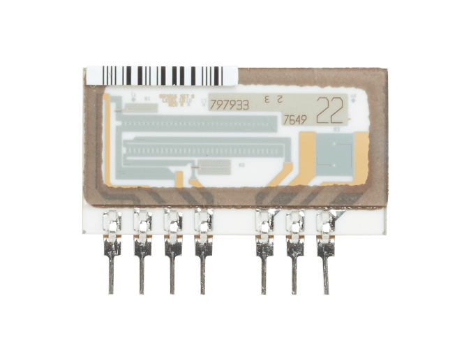
LTFLU-1CH die photo. Courtesy branadic (Dipl.-Ing. A. Bülau) from the EEVBlog
On the die photo we can see much more complex design than just diode and transistor.
Instruments list using Ref-Amp
Known instruments to implement SZA263/LTFLU-1AH as primary DC reference:
- Fluke 341A DC Voltage Calibrator
- Fluke 343A DC Voltage Calibrator
- Fluke 515 Portable calibrator
- Philips PM2530 7½-digit DMM
- Fluke 8840A DMM
- Fluke 8842A DMM
- Fluke 8508A DMM
- Fluke 8588 and 8558A DMM
- Fluke 731B DC Voltage Standard
- Fluke 732A DC Voltage Standard
- Fluke 732B DC Voltage Standard
- Fluke 732C DC Voltage Standard
- Fluke 5440B DC calibrator
- “Fluke 5500A Multi-function calibrator”
- “Fluke 5502A Multi-function calibrator”
- “Fluke 5520A Multi-function calibrator”
- Fluke 5522A Multi-function calibrator
- Fluke 57LFC System Calibrator
- Fluke 5700A Multi-function calibrator
- Fluke 5720A Multi-function calibrator
- Fluke 5730A Multi-function calibrator
- Fluke 5790A AC Measurement standard
- Fluke 5790B AC Measurement standard
- Keithley DMM7510 7½-digit multimeter
There is also great thread here on EEVBlog created by lymex, revealing guts of various DC voltage standards.
Refurbishment of S/N 3675006 732A unit
In this section of the article I’ll demonstrate the exact steps required to refresh and test old but still very much capable Fluke 732A DC Voltage standard S/N 3675006.
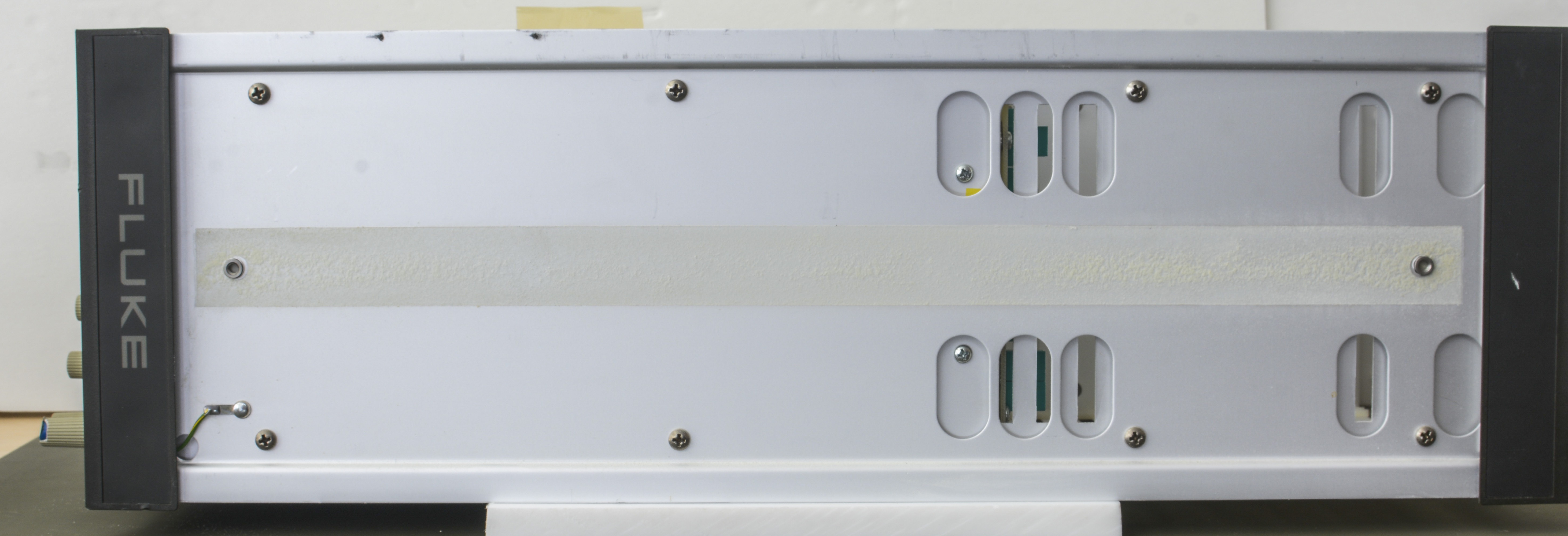
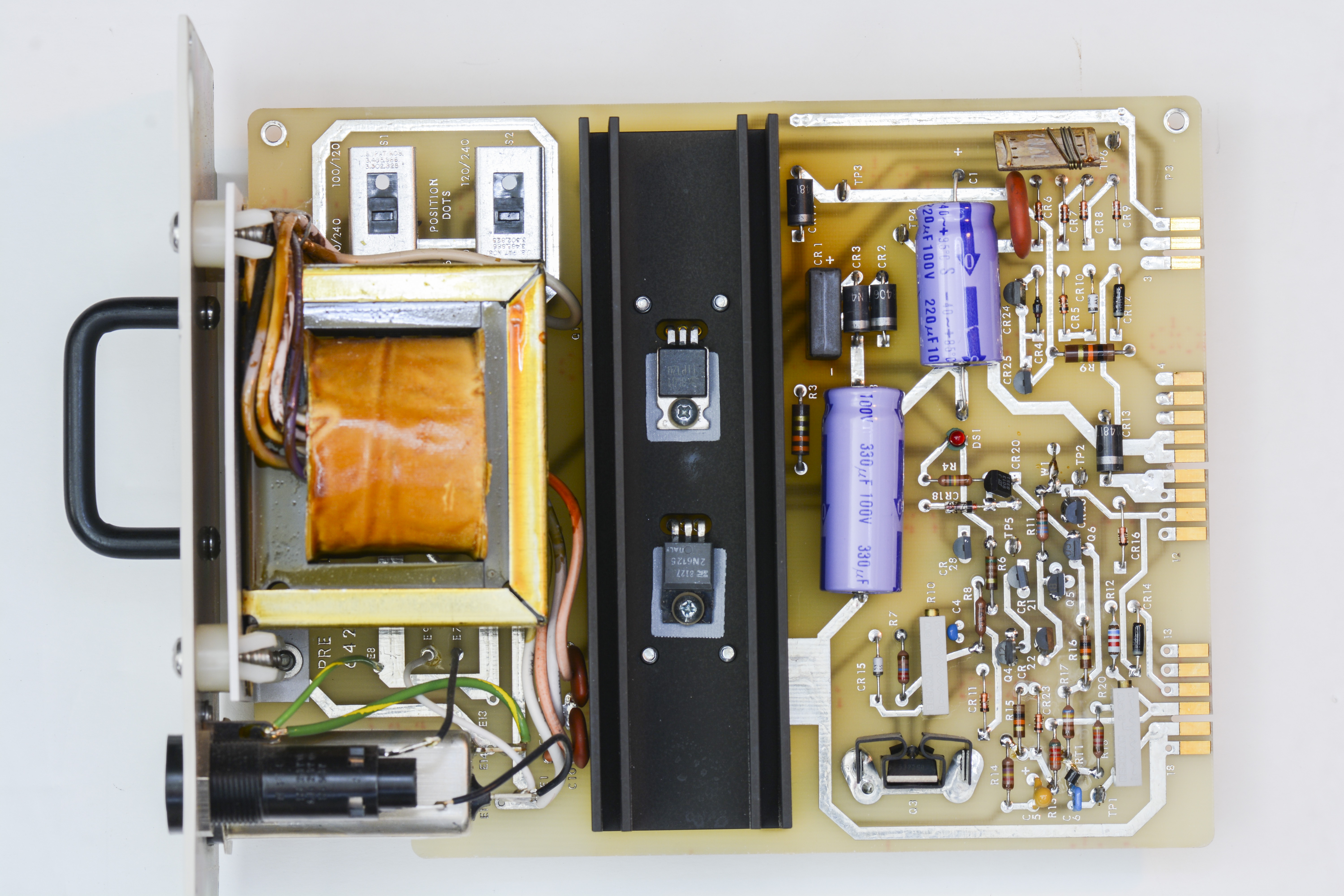
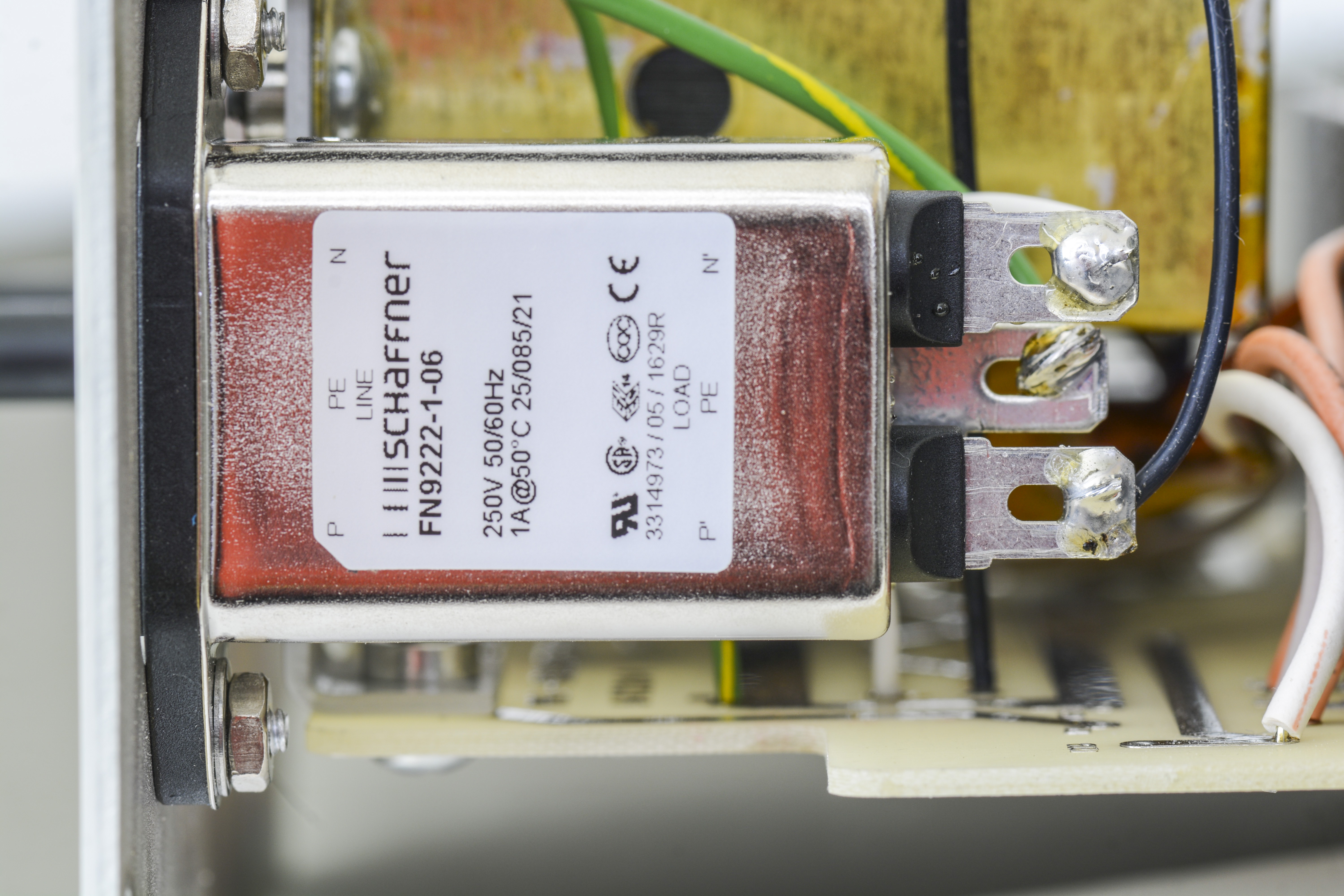
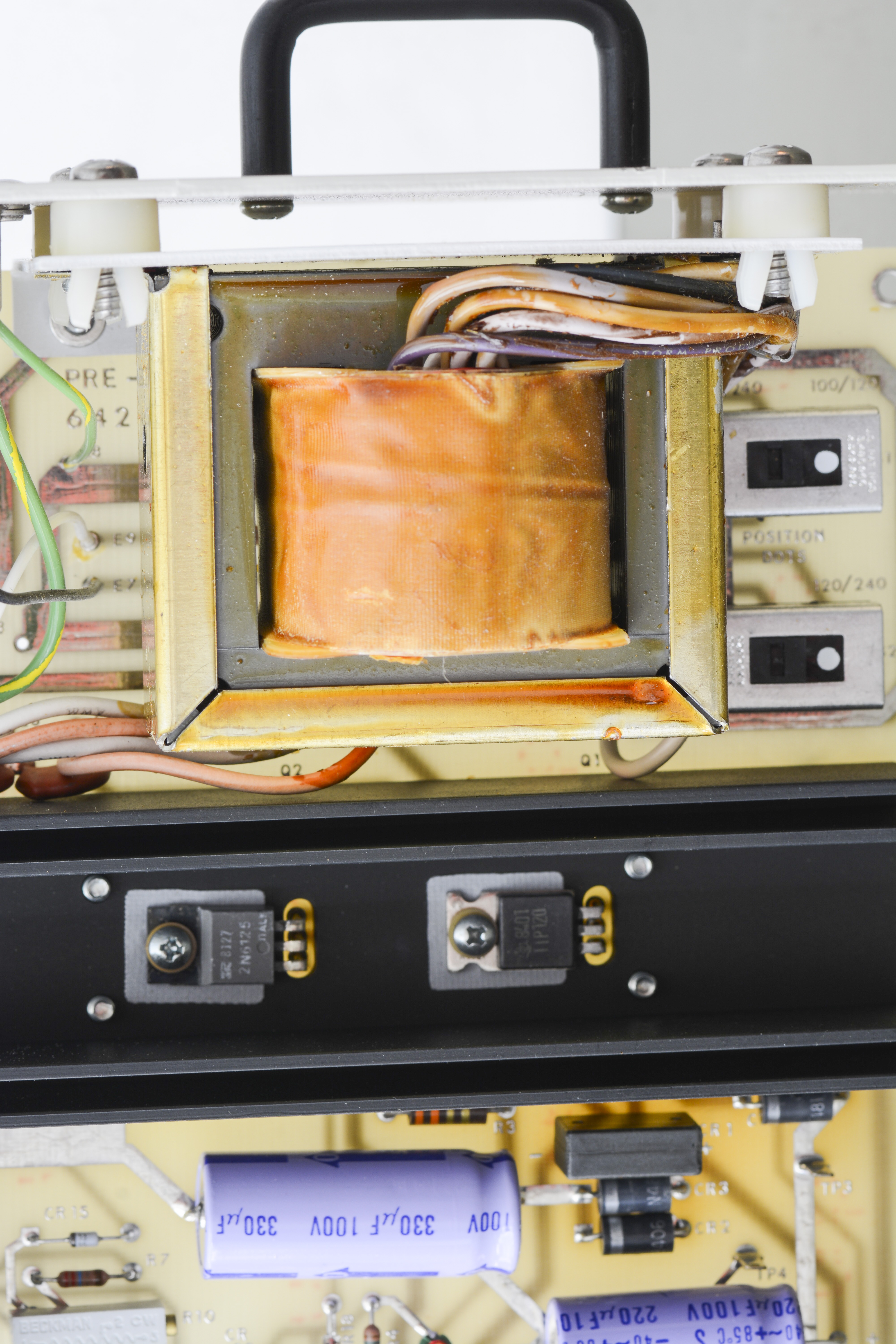
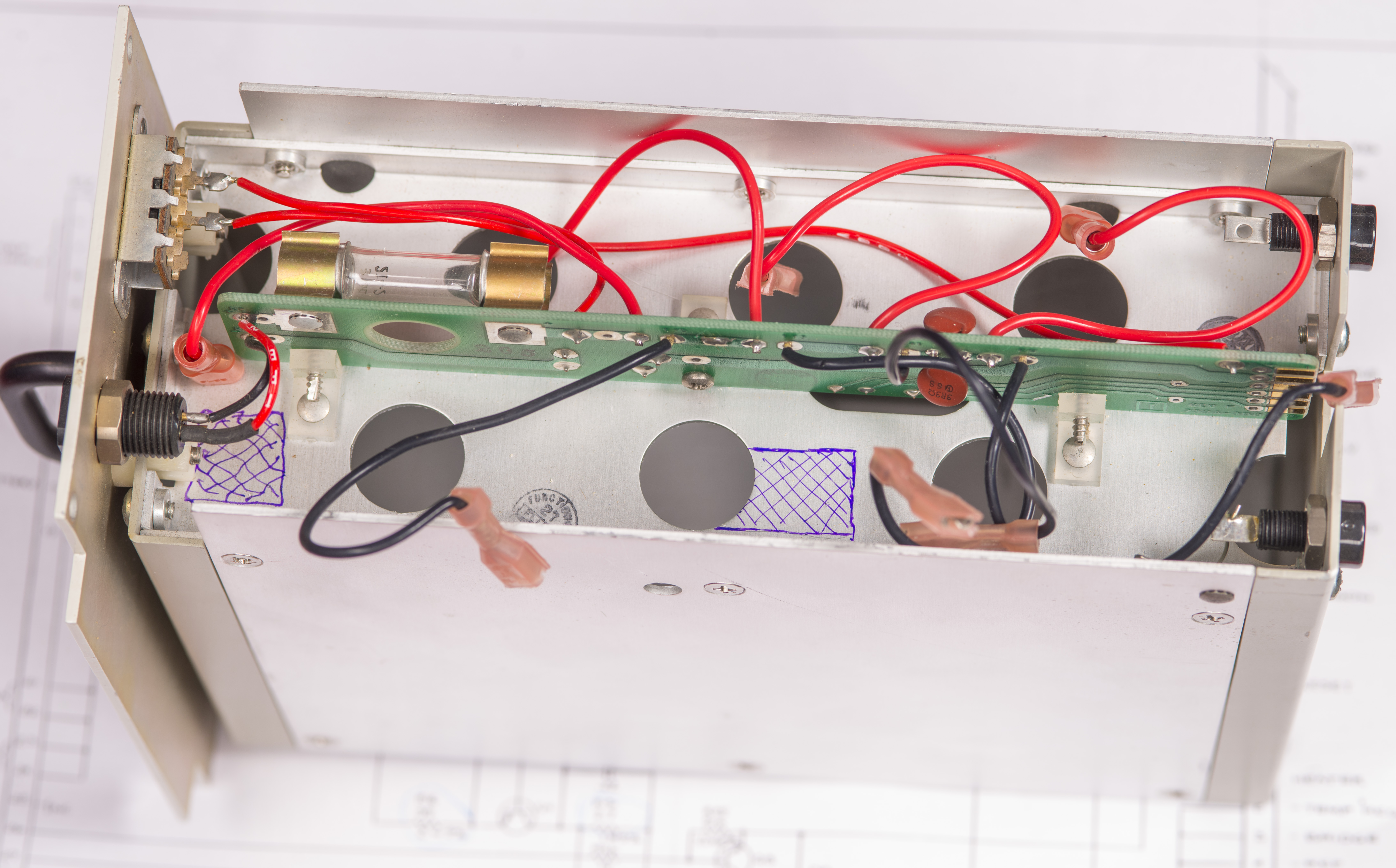
A3 Pre-regulator and mains entry PCBA
Image 2: A3 pre-regulator assembly, top side as received
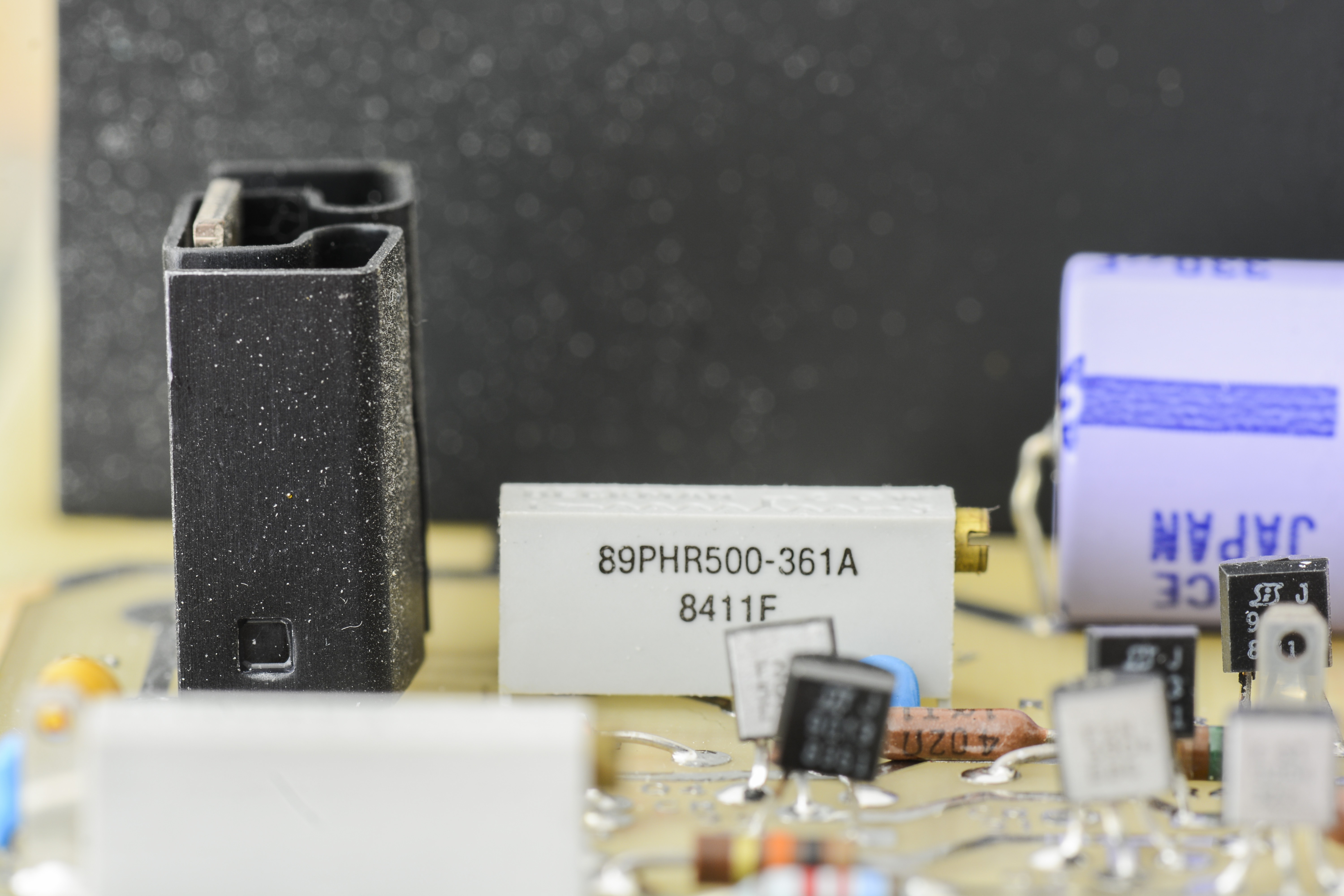
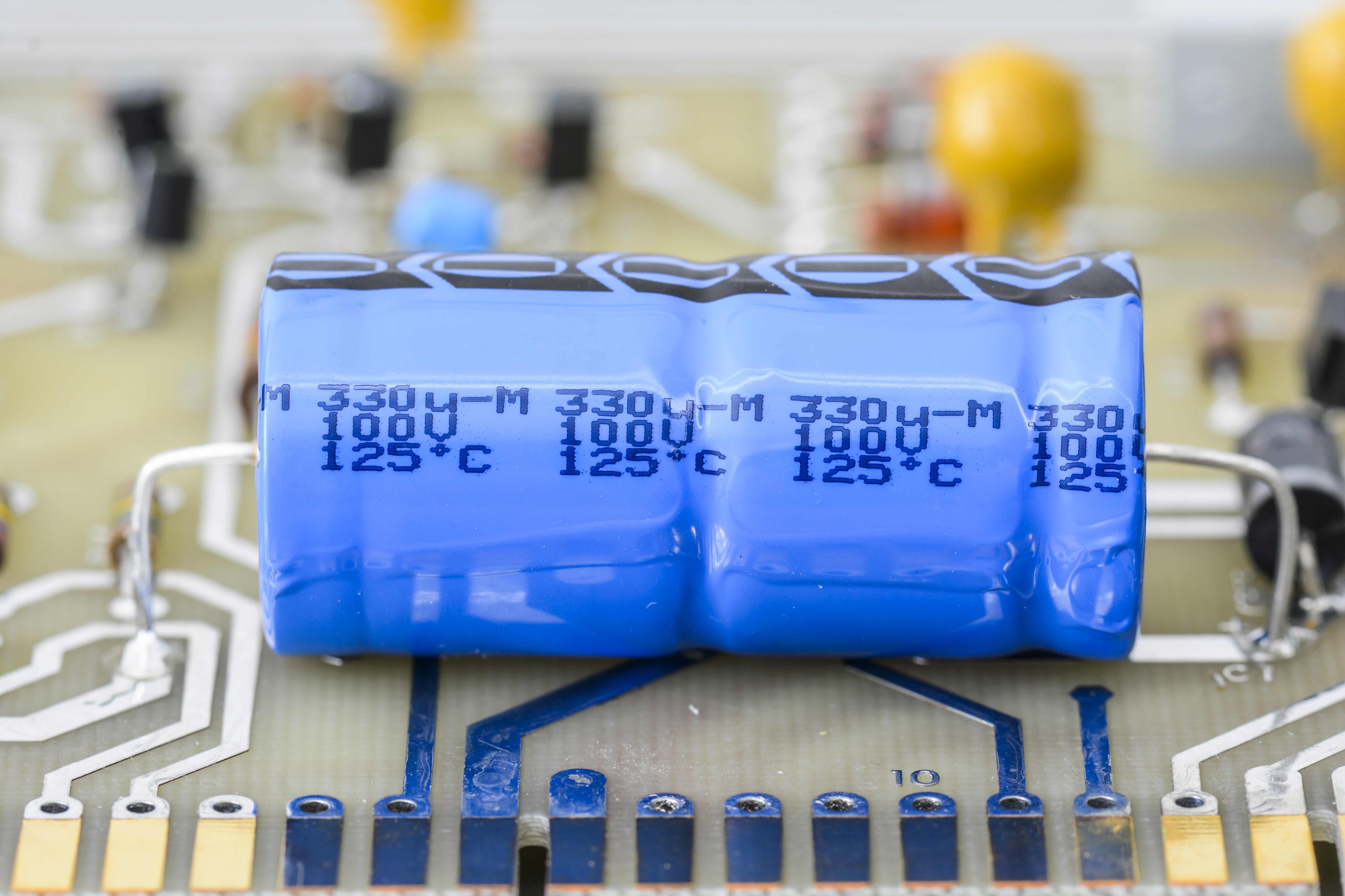
On this board we get two large axial electrolytes, 330 µF and 220 µF, both rated for 100 V, one tiny 1 µF 35 V tantalum capacitor, some carbon composition resistors (3.3 Ω, 510 Ω and two 10 kΩ) as well as mains filter with C14 receptacle.
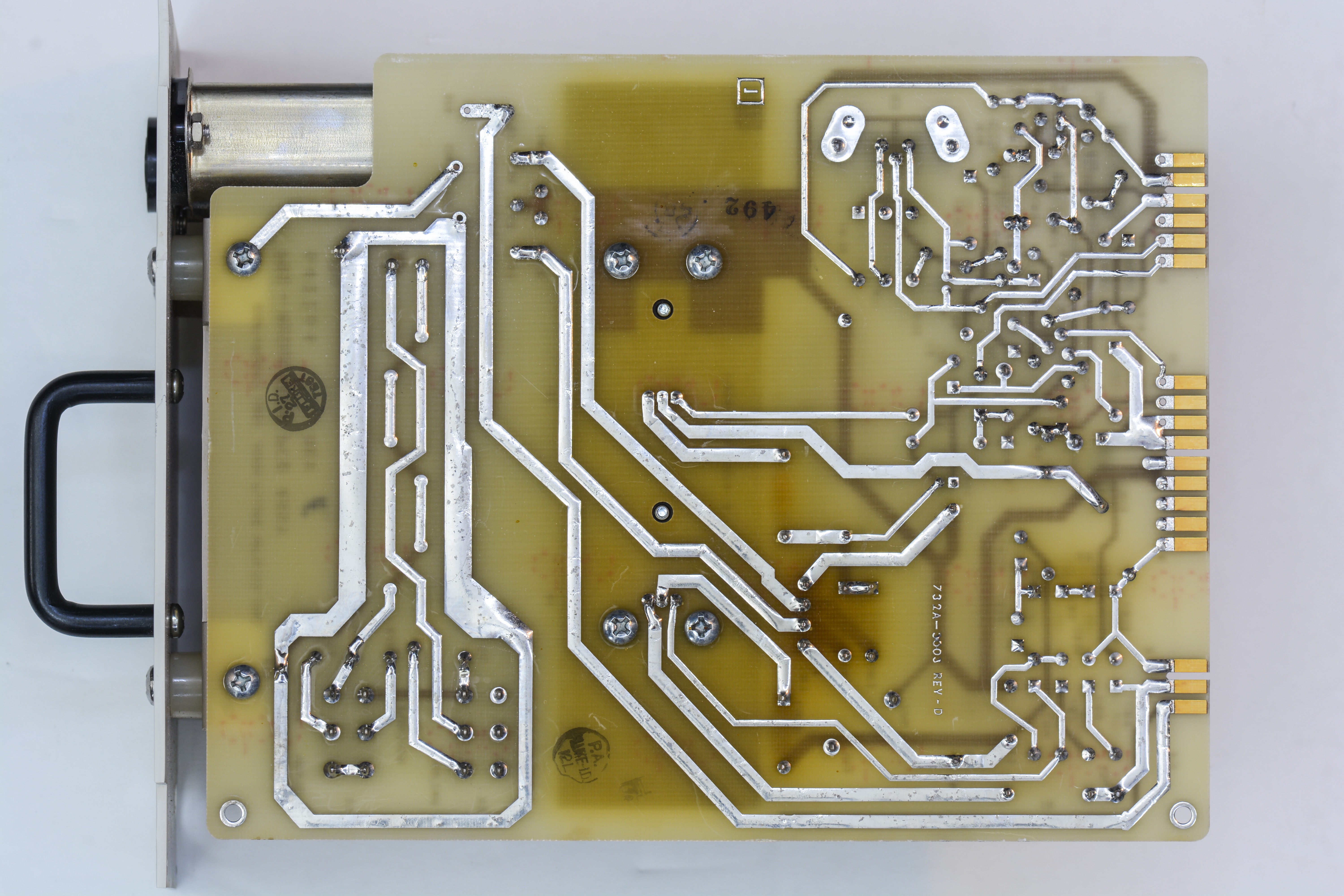
Image 3: A3 pre-regulator assembly, bottom side
This is a newer revision of the board without the RT1 thermistor. Ensure you use the correct schematics and service manual when working on this module. Additionally, I have replaced the old, cracked insulator washers for the TO-220-3 transistors on the heatsink with modern PPS washers. After replacing these parts, insulation between the metal heatsink and the transistor bodies was verified to ensure proper isolation.
Image 4: A3 pre-regulator with cut capacitor
As we can see in “as received” photo some capacitor already snipped off to make our job easier :)
Image 5: Overview on A3 assembly module
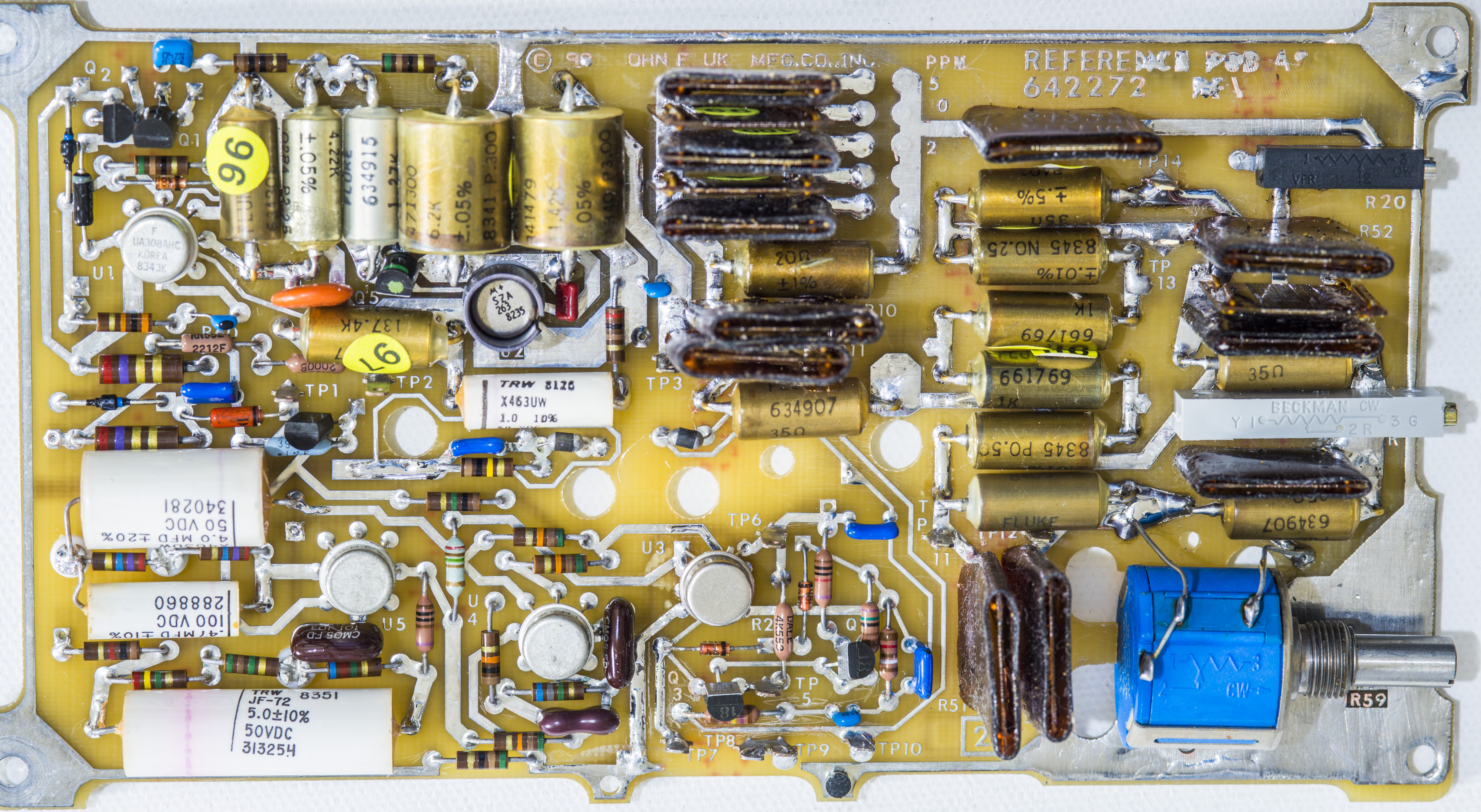
A4 Regulator PCBA
This PCB used to control and manage battery charging/level and power to the oven/zener assembly.
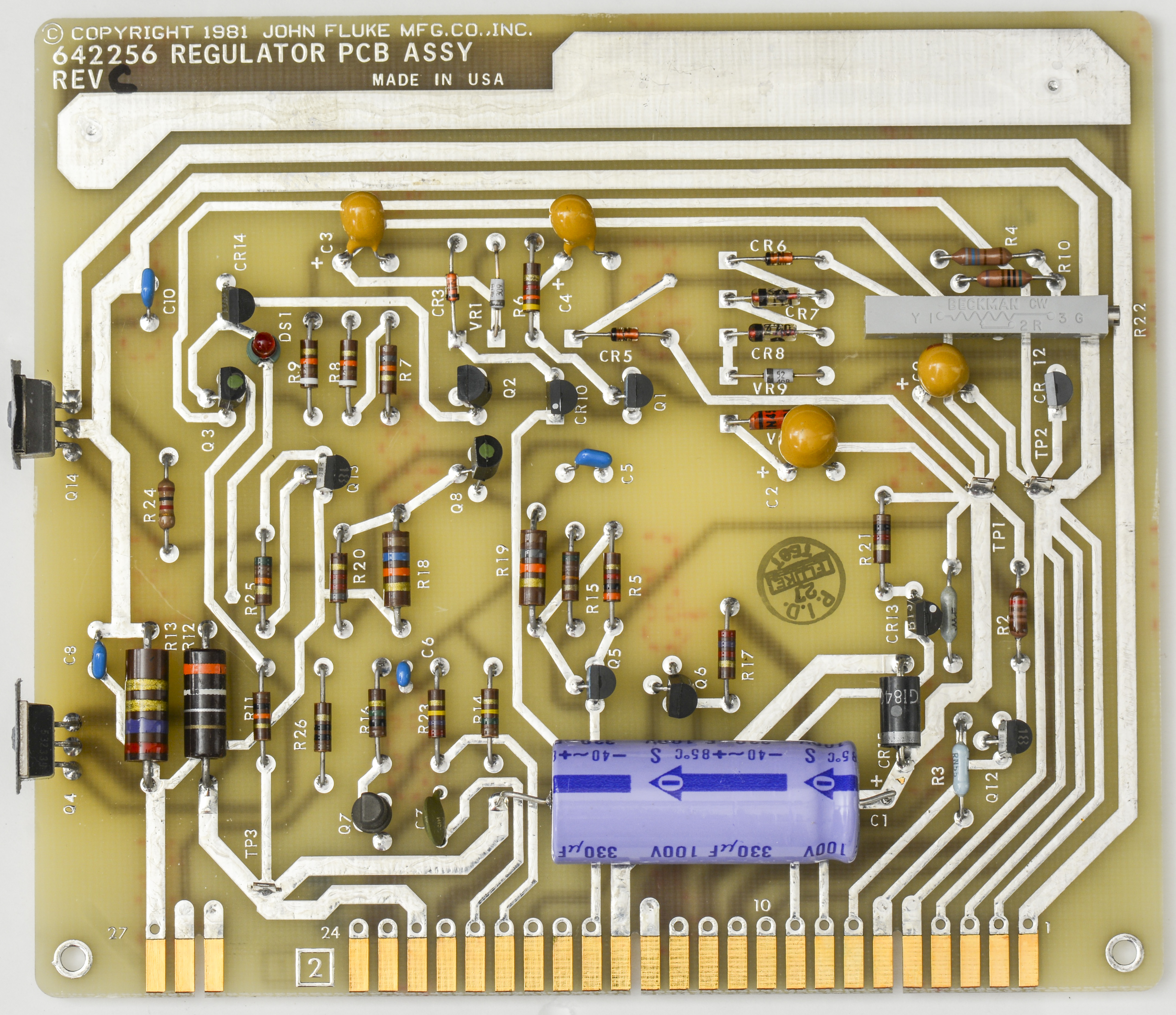
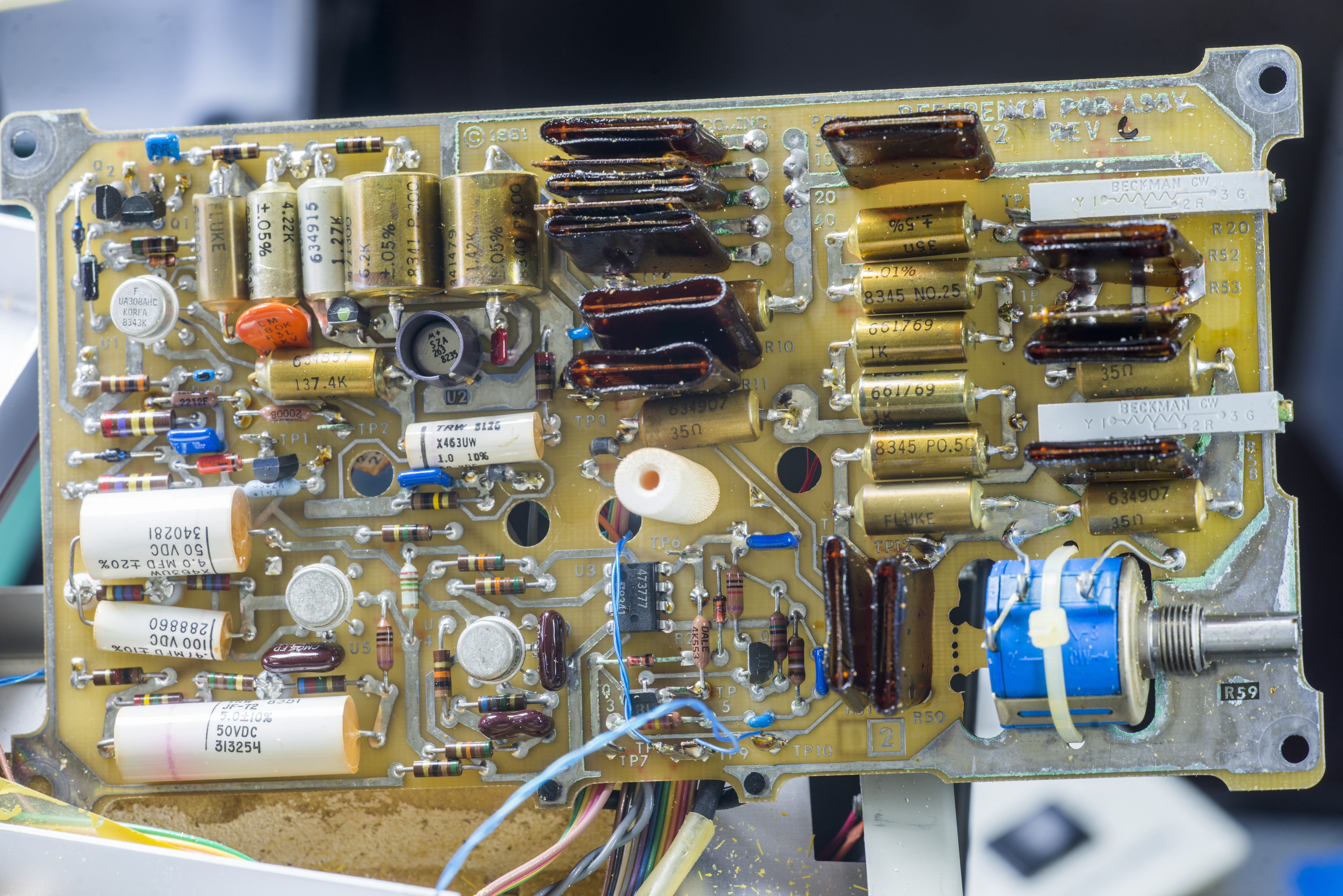
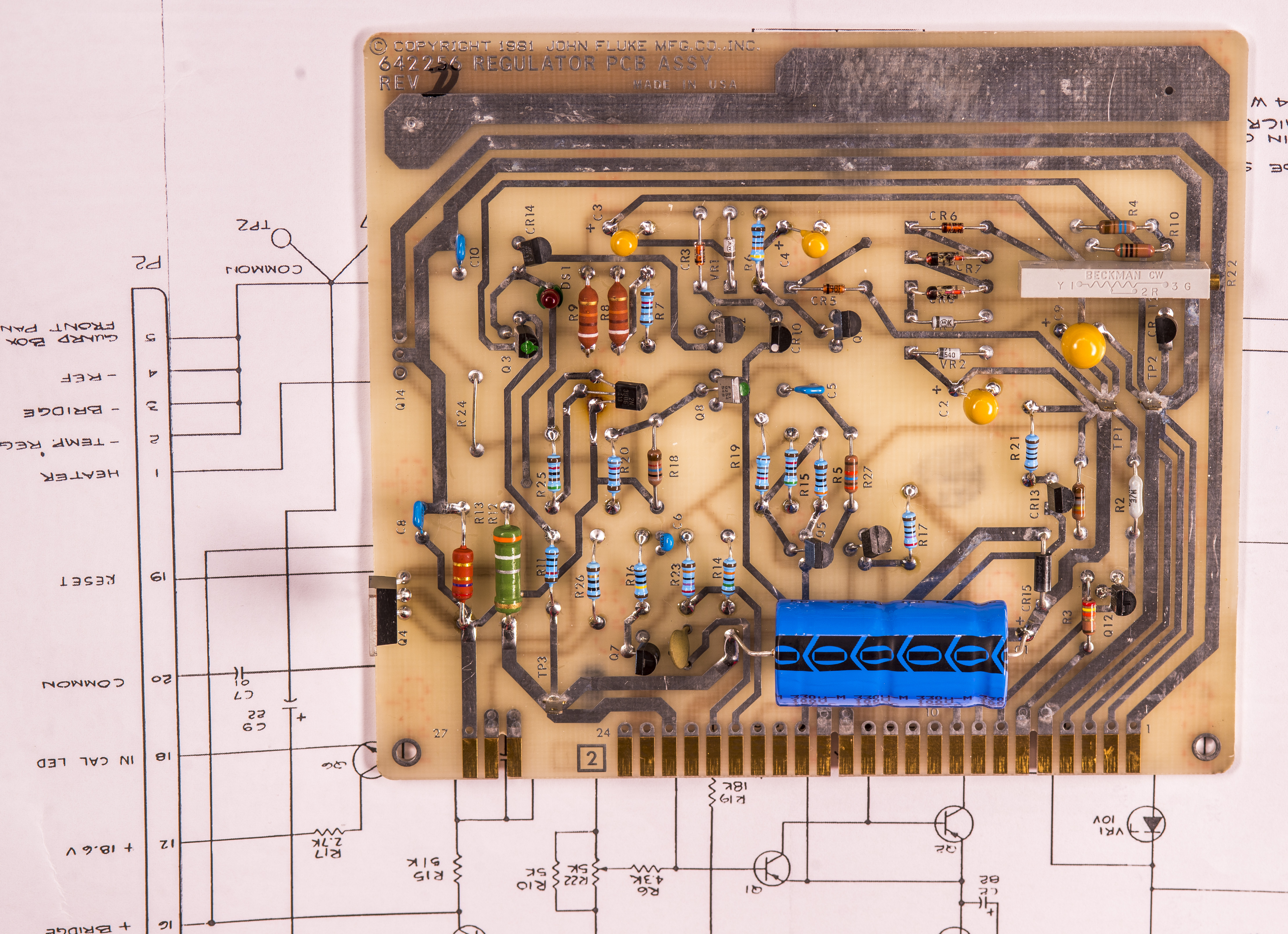
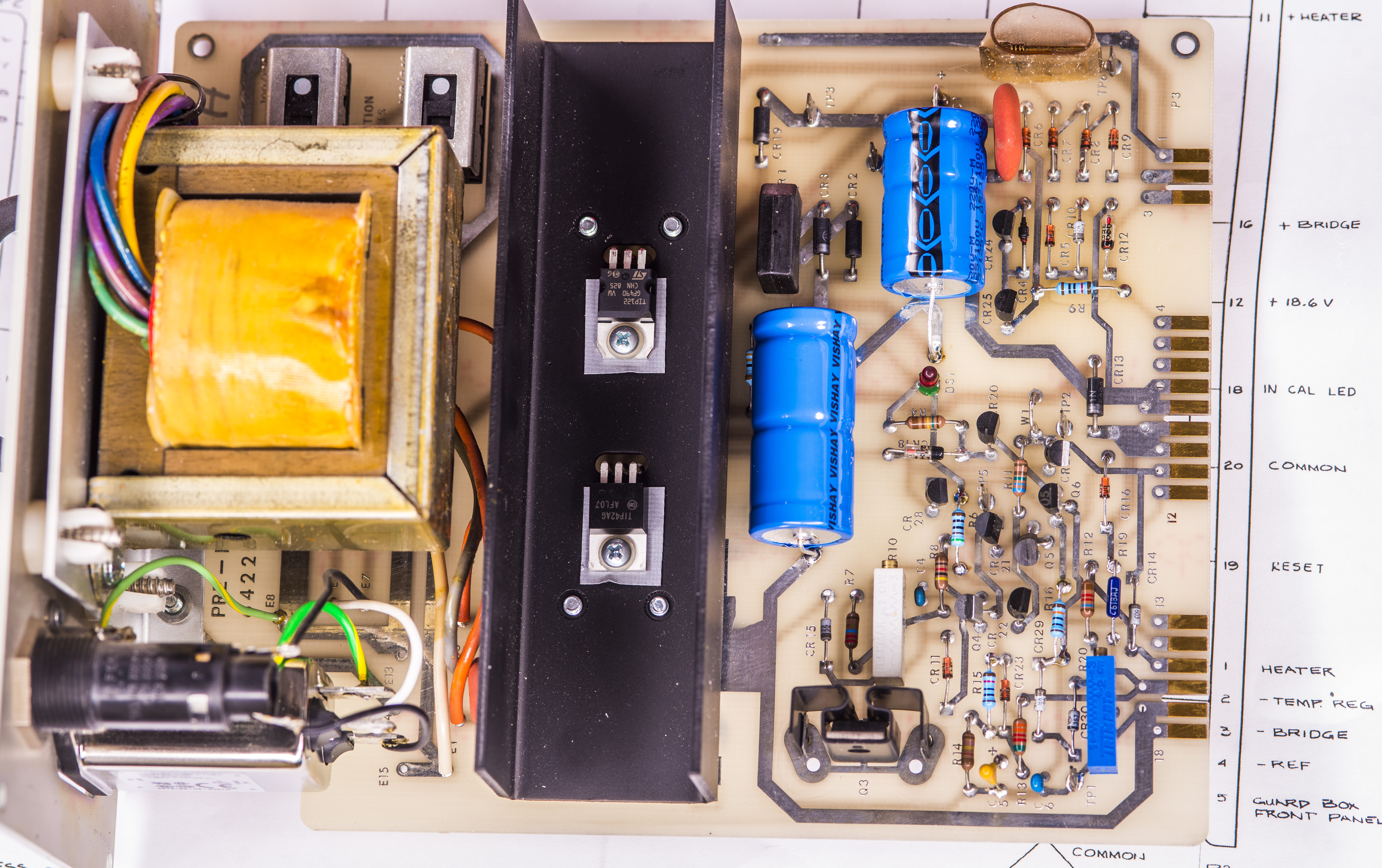
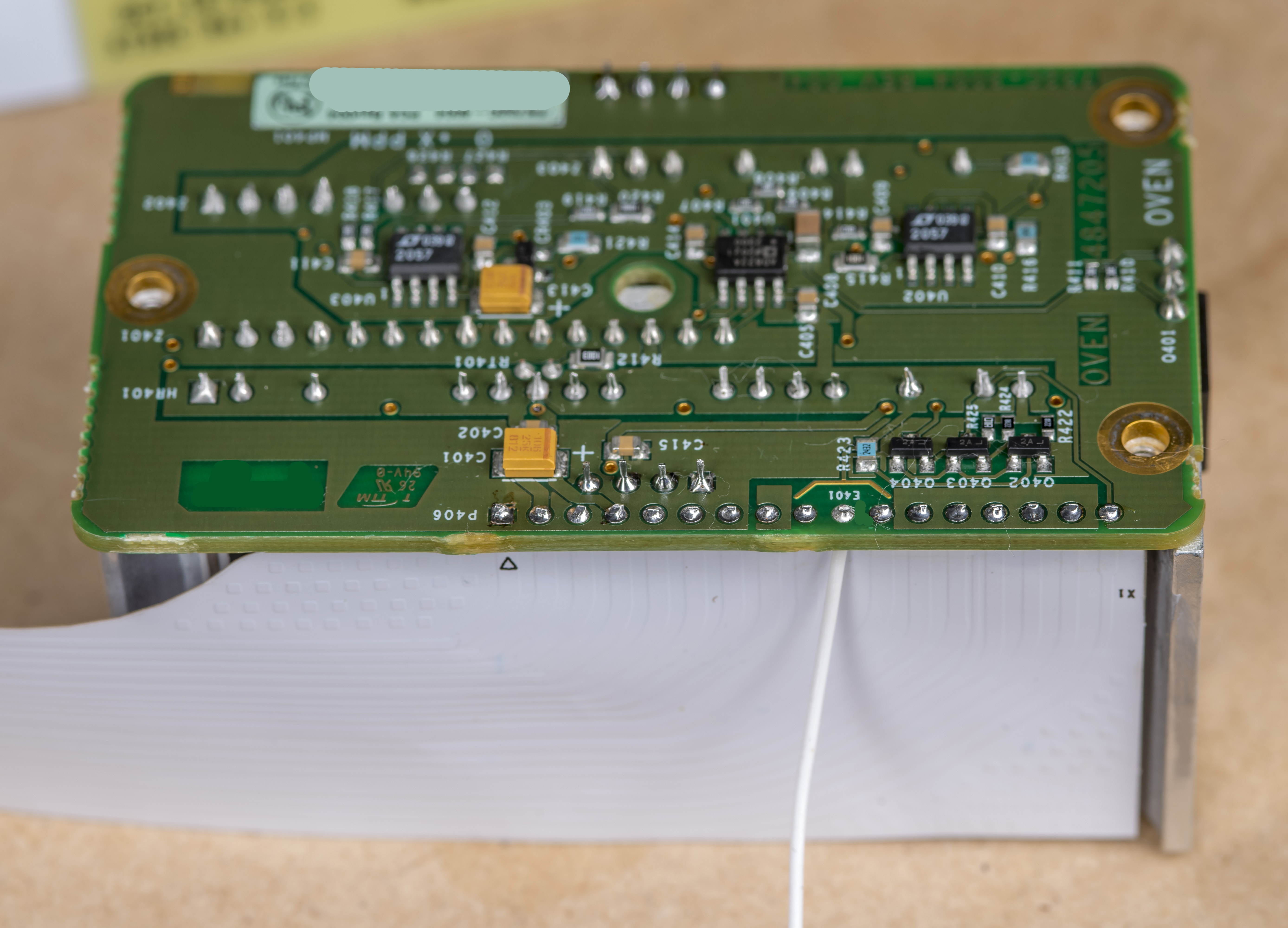
Image 6: Regulator PCBA as received, top side
Based on the datecode markings this 732A was assembled around 39 week 1984, good fourty (!) years ago.
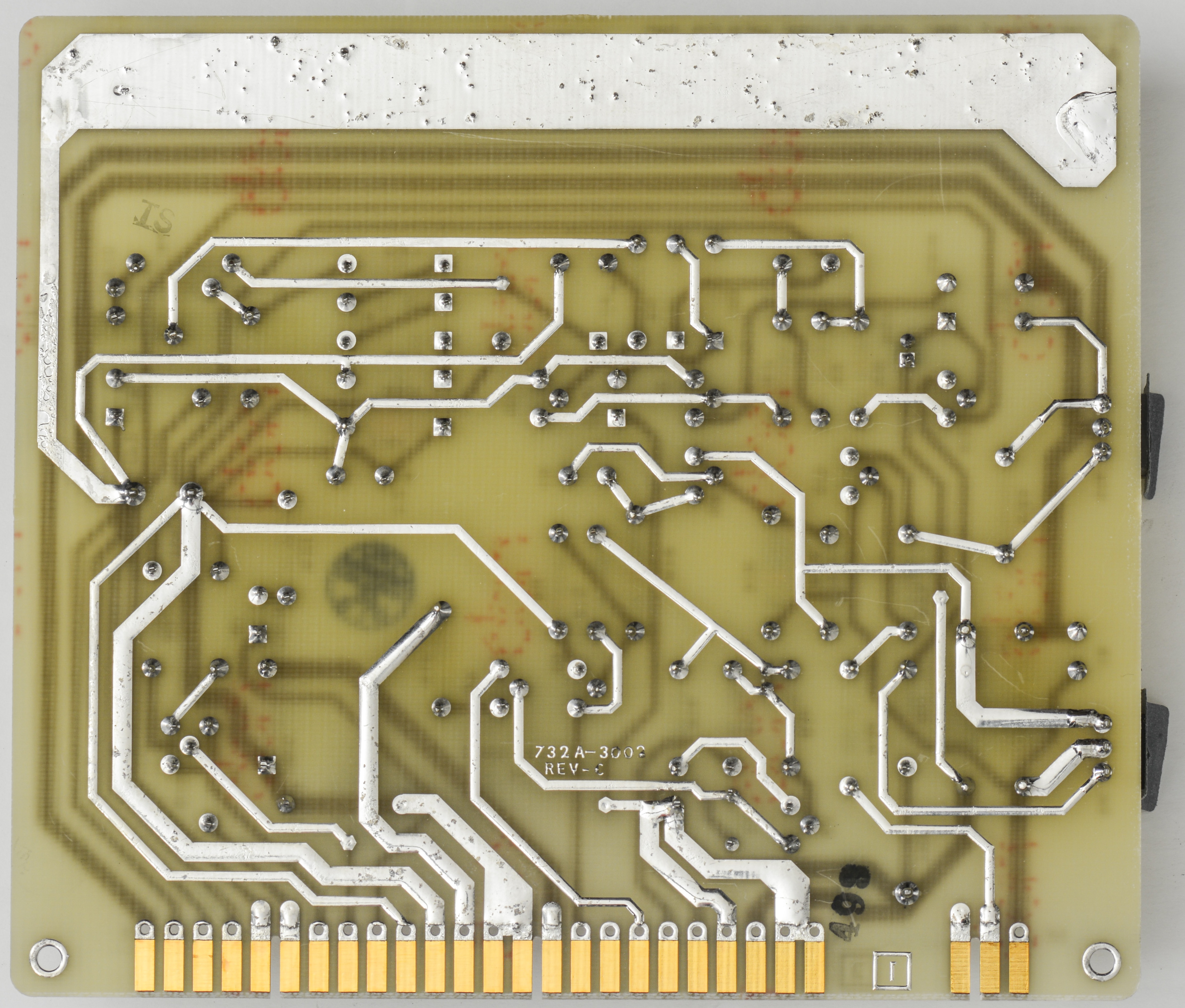
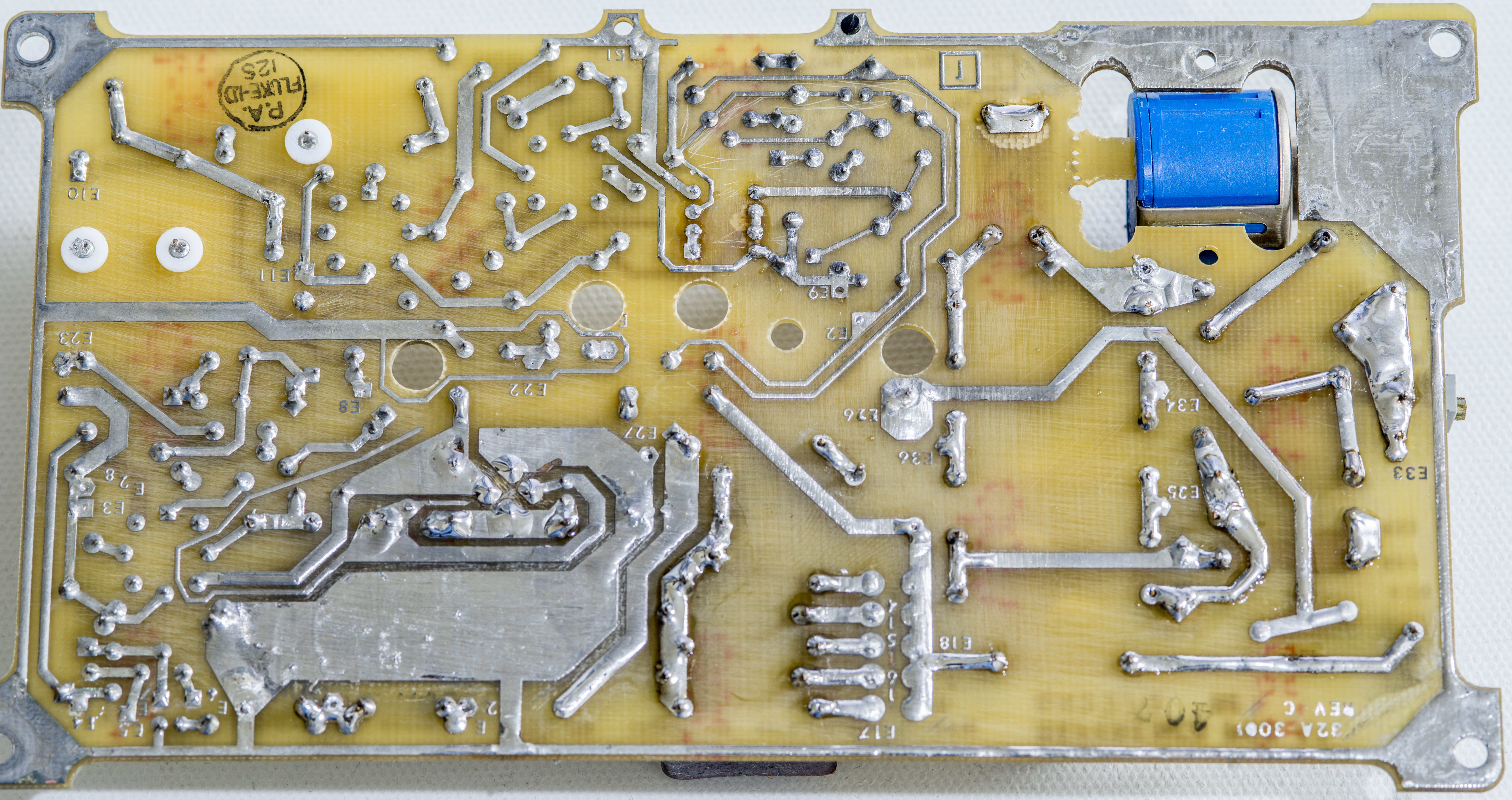
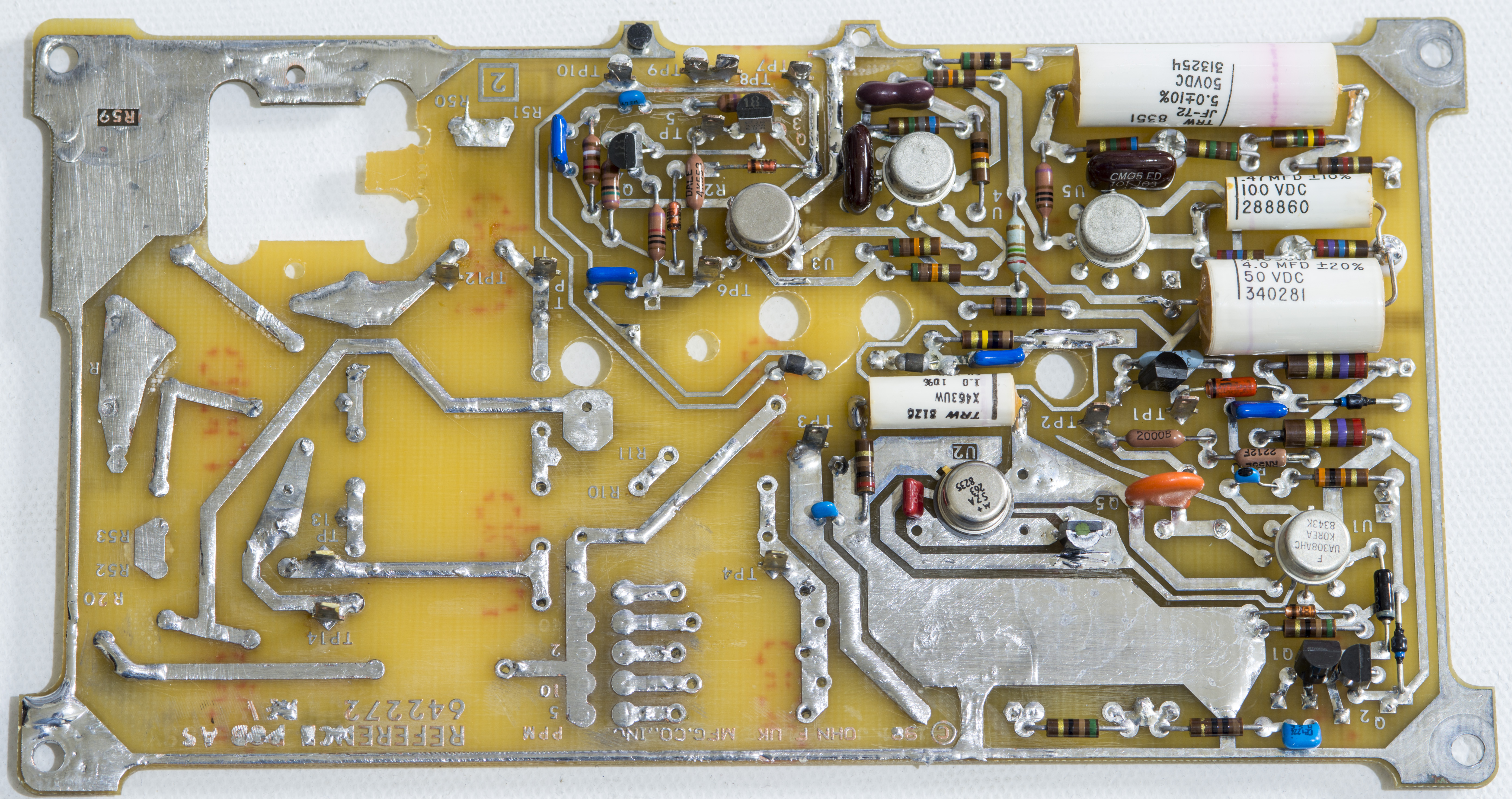
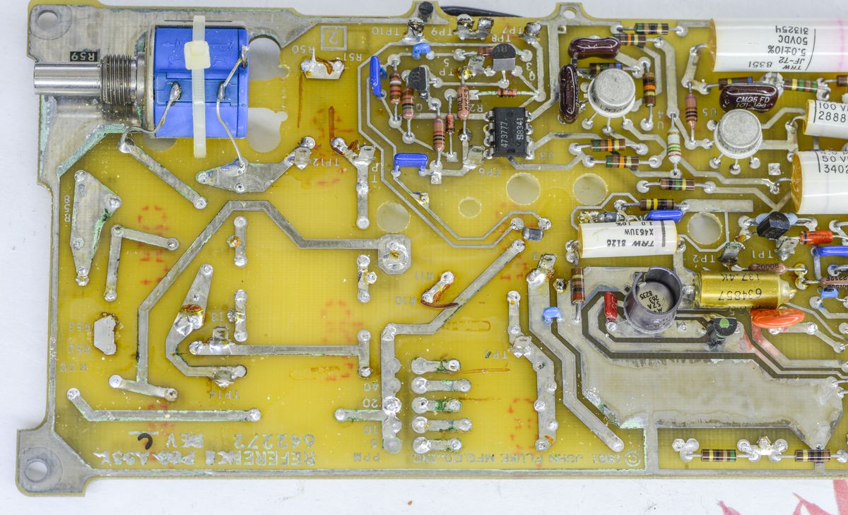
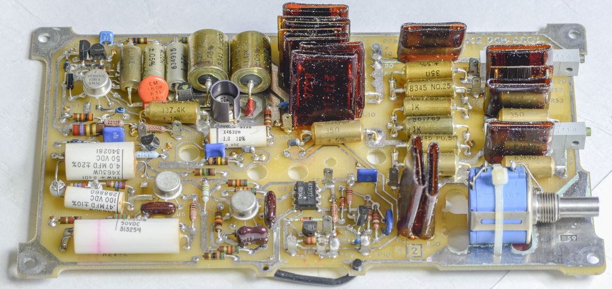
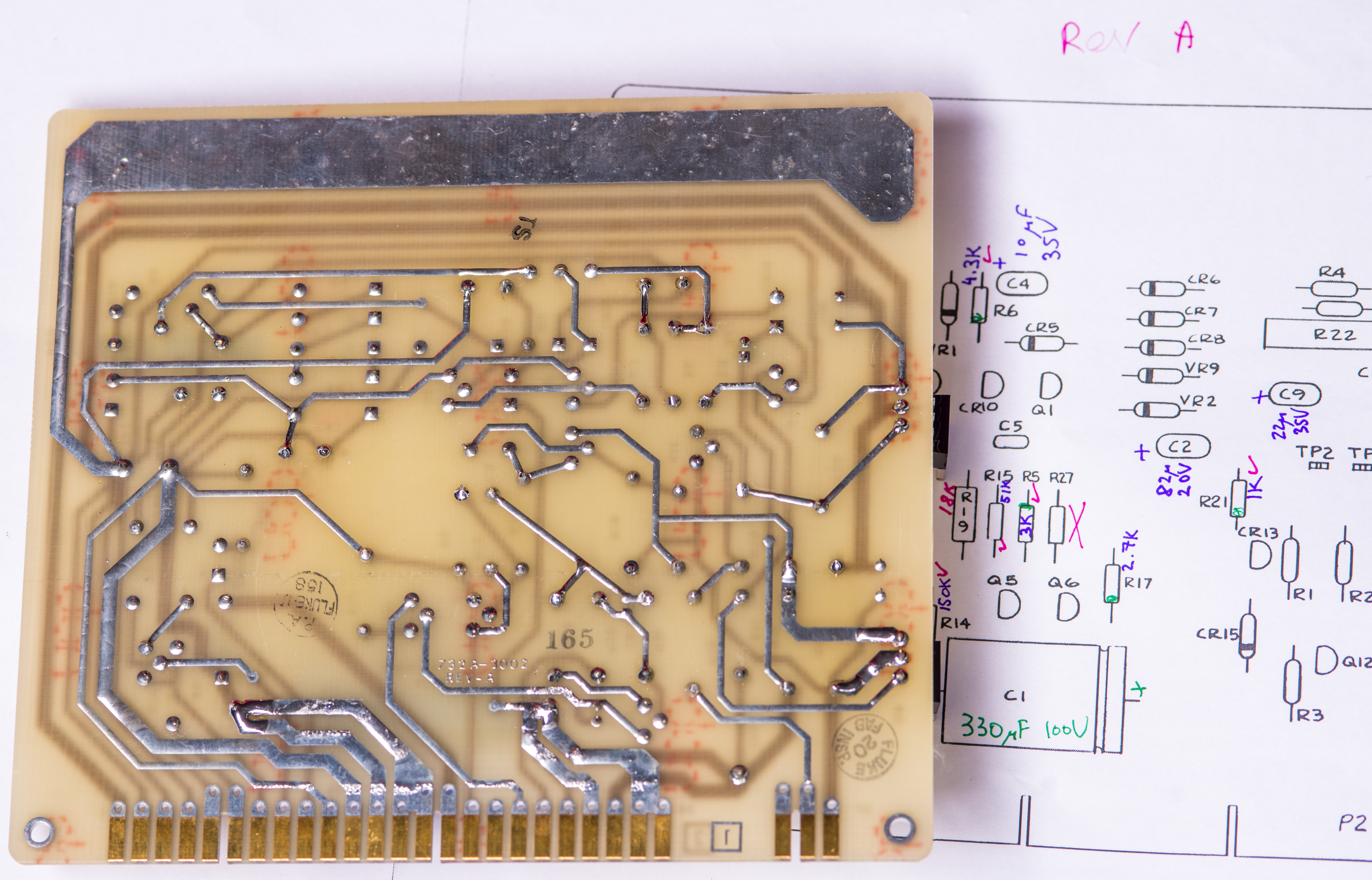
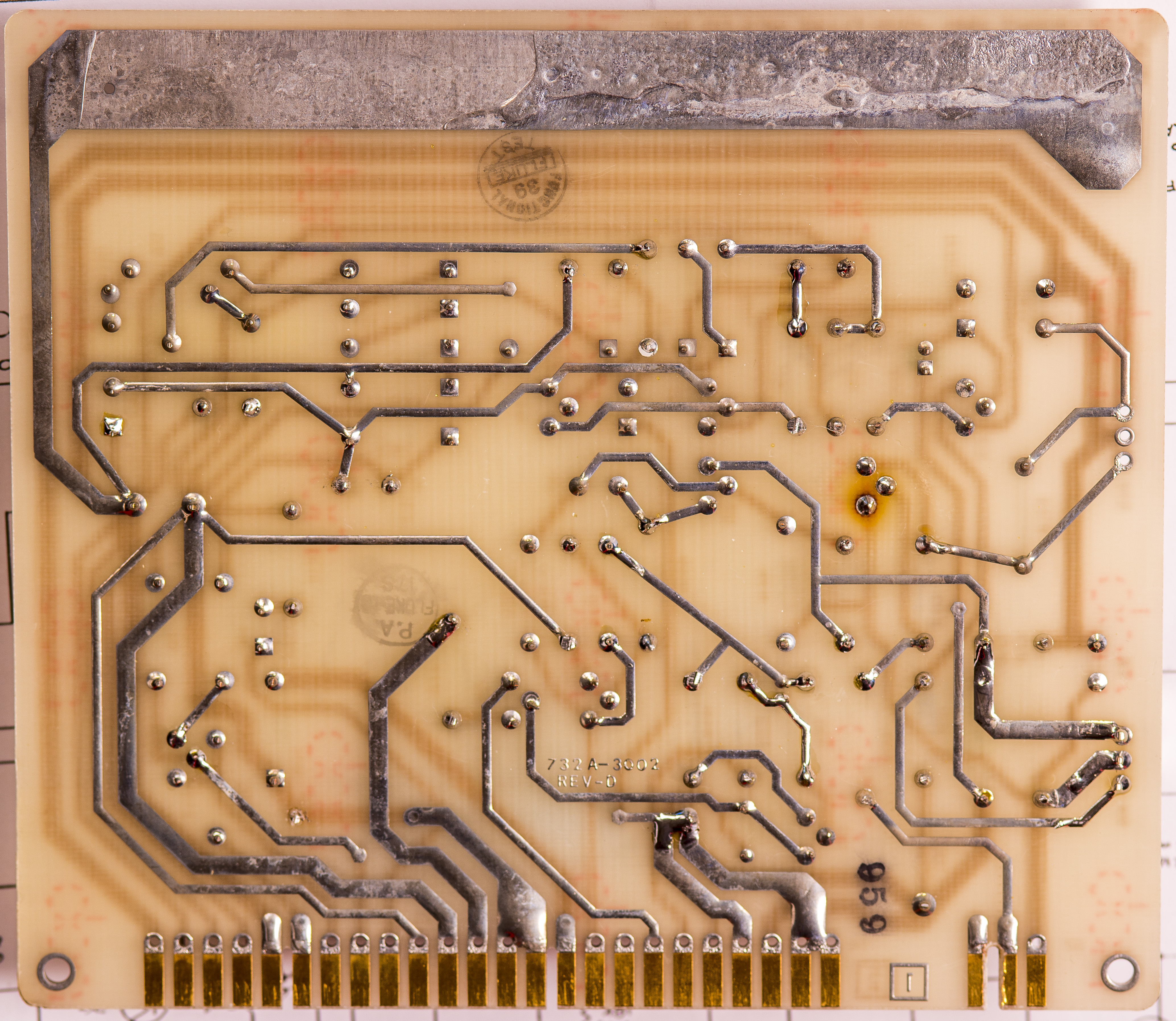
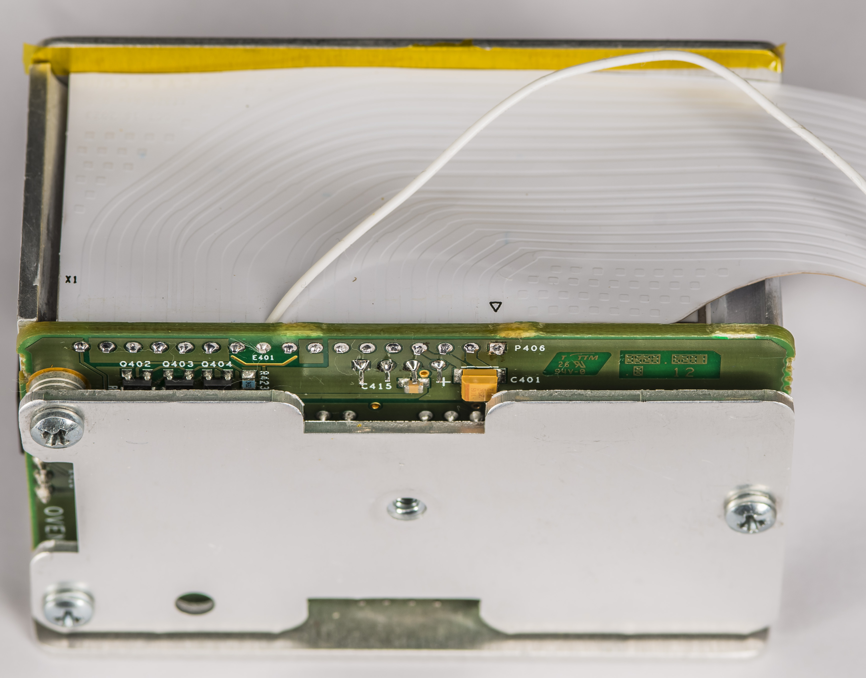
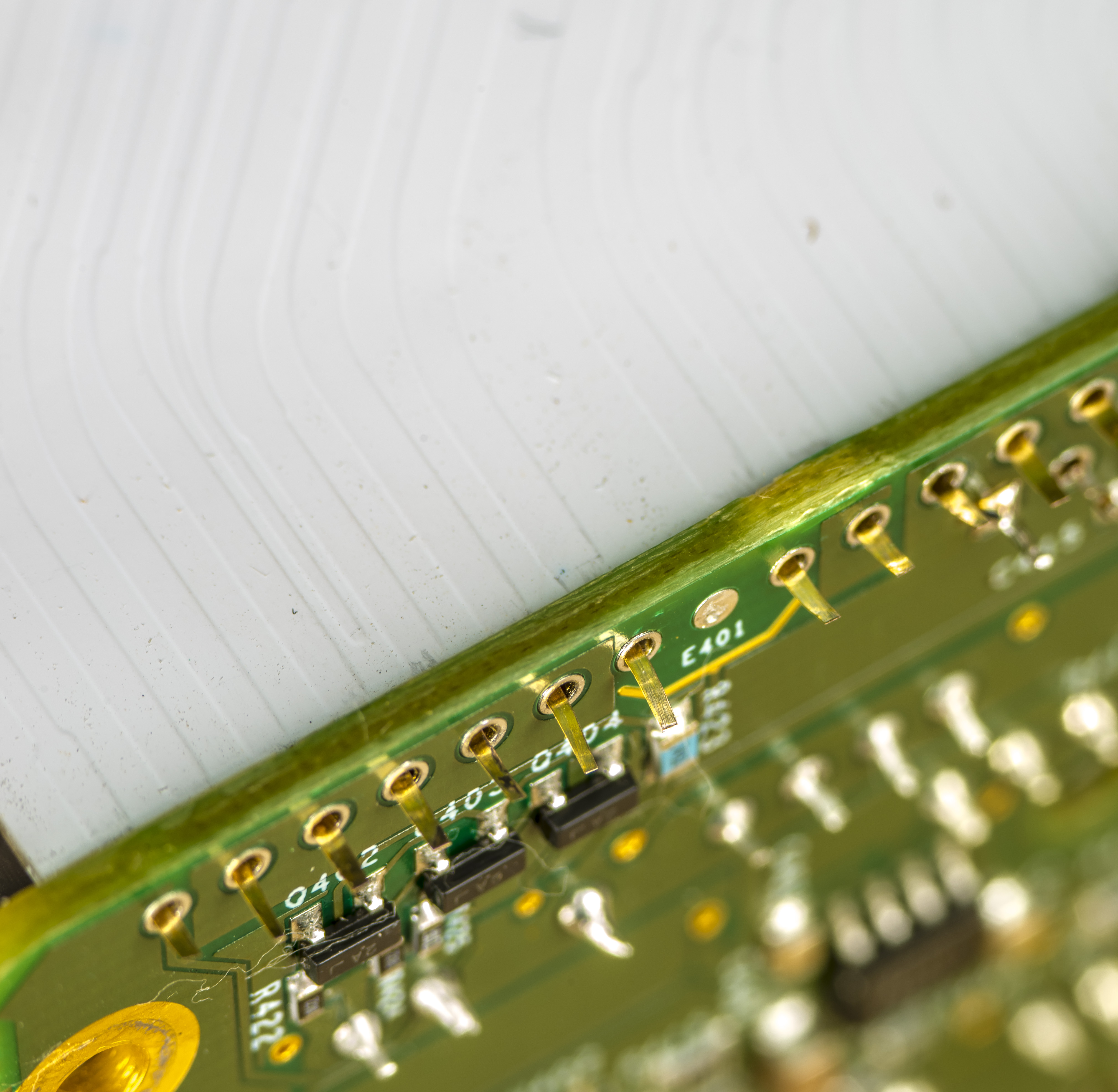
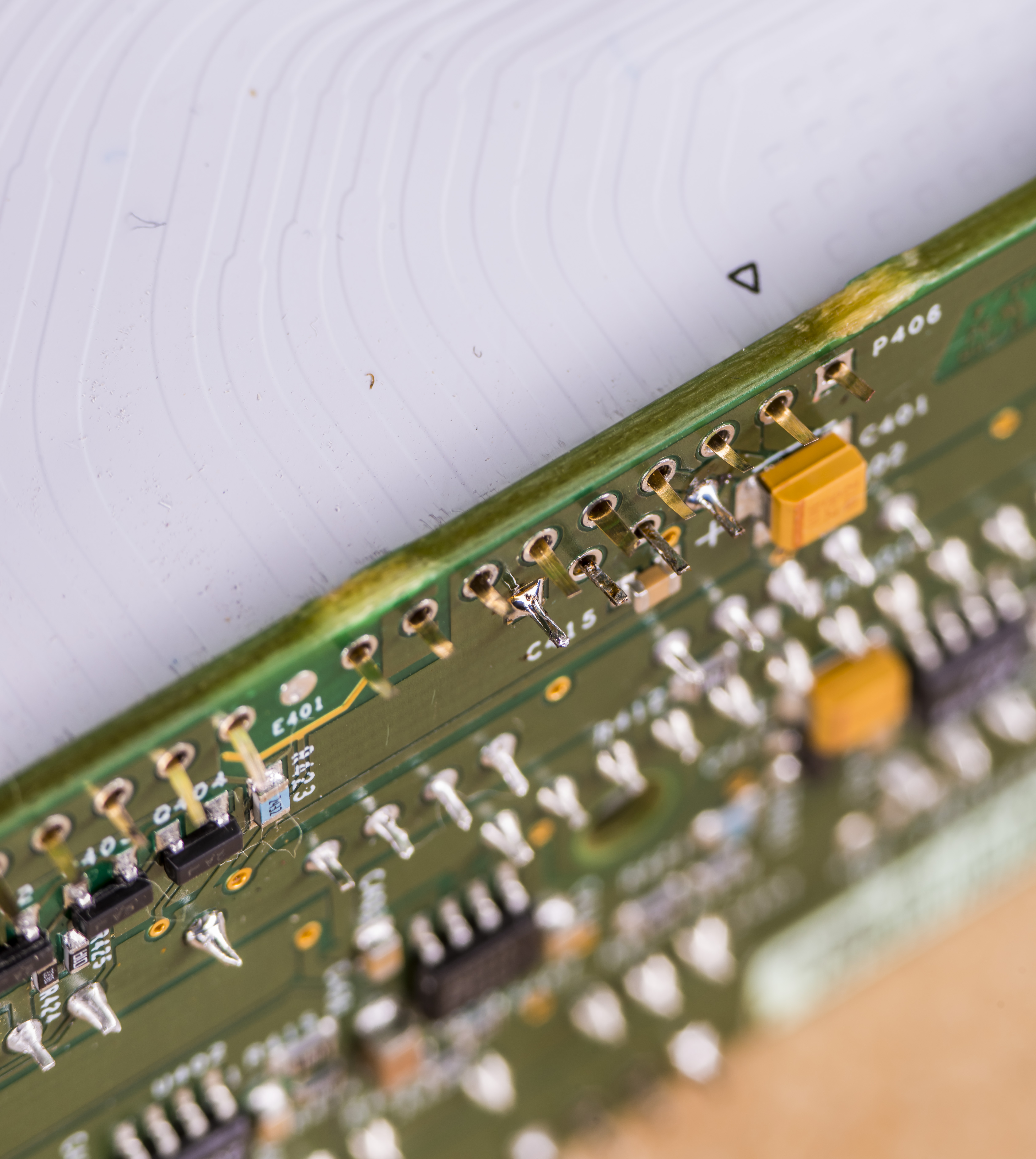
Image 7: Regulator PCBA as received, bottom side
There are four yellow smoke-containing tantalum capacitors on this assembly.
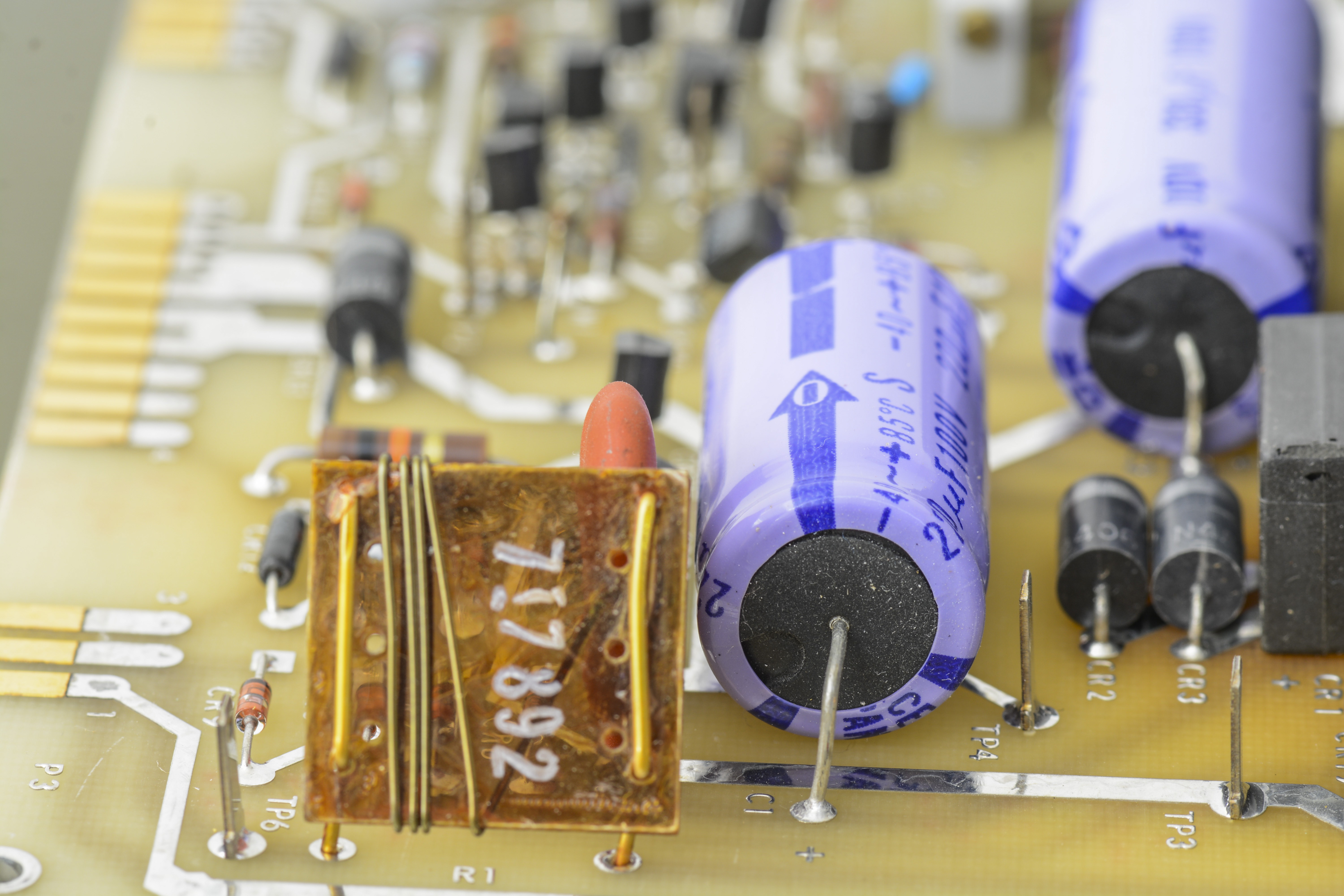
Image 8: Tantalum capacitors on the A4 PCBA
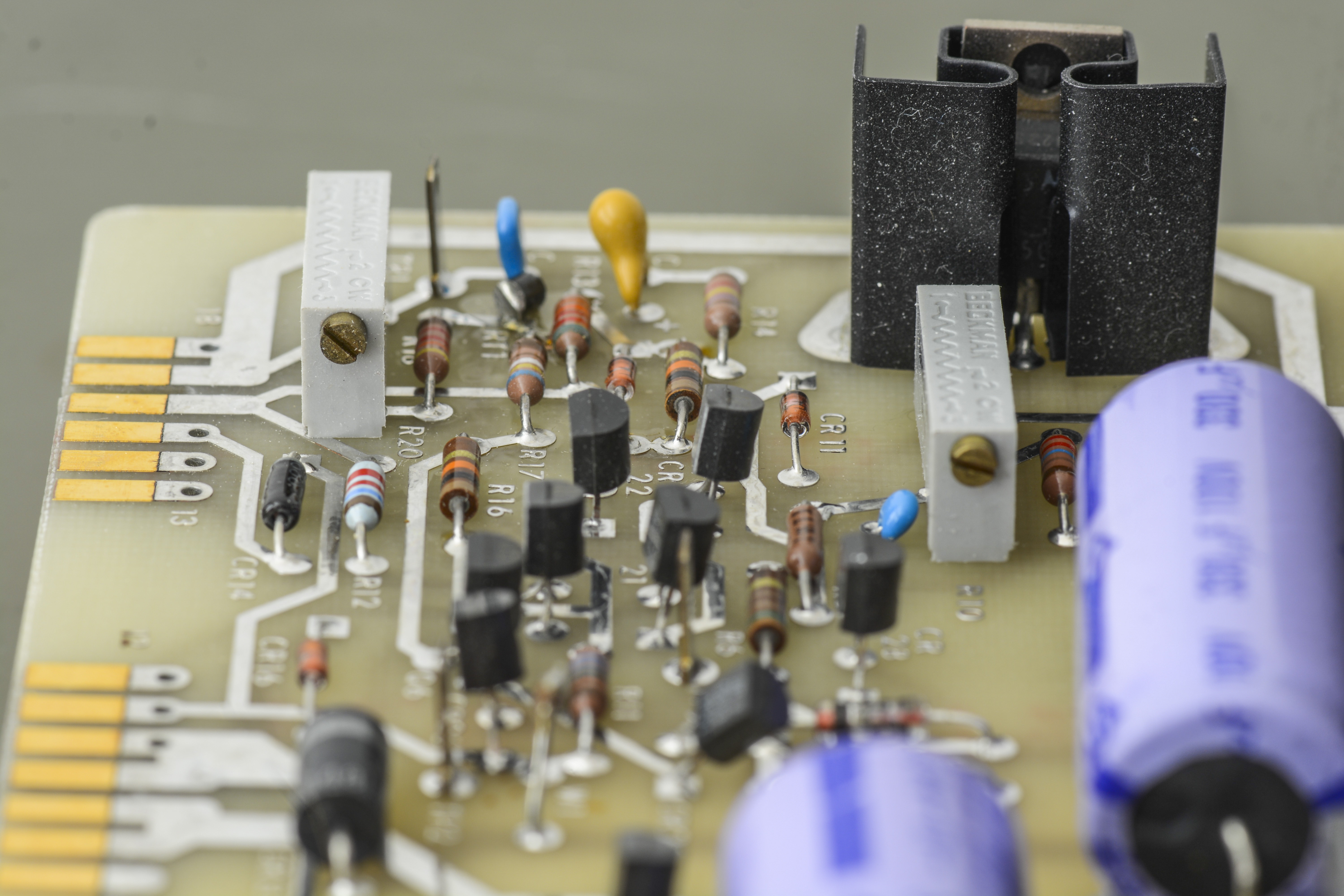
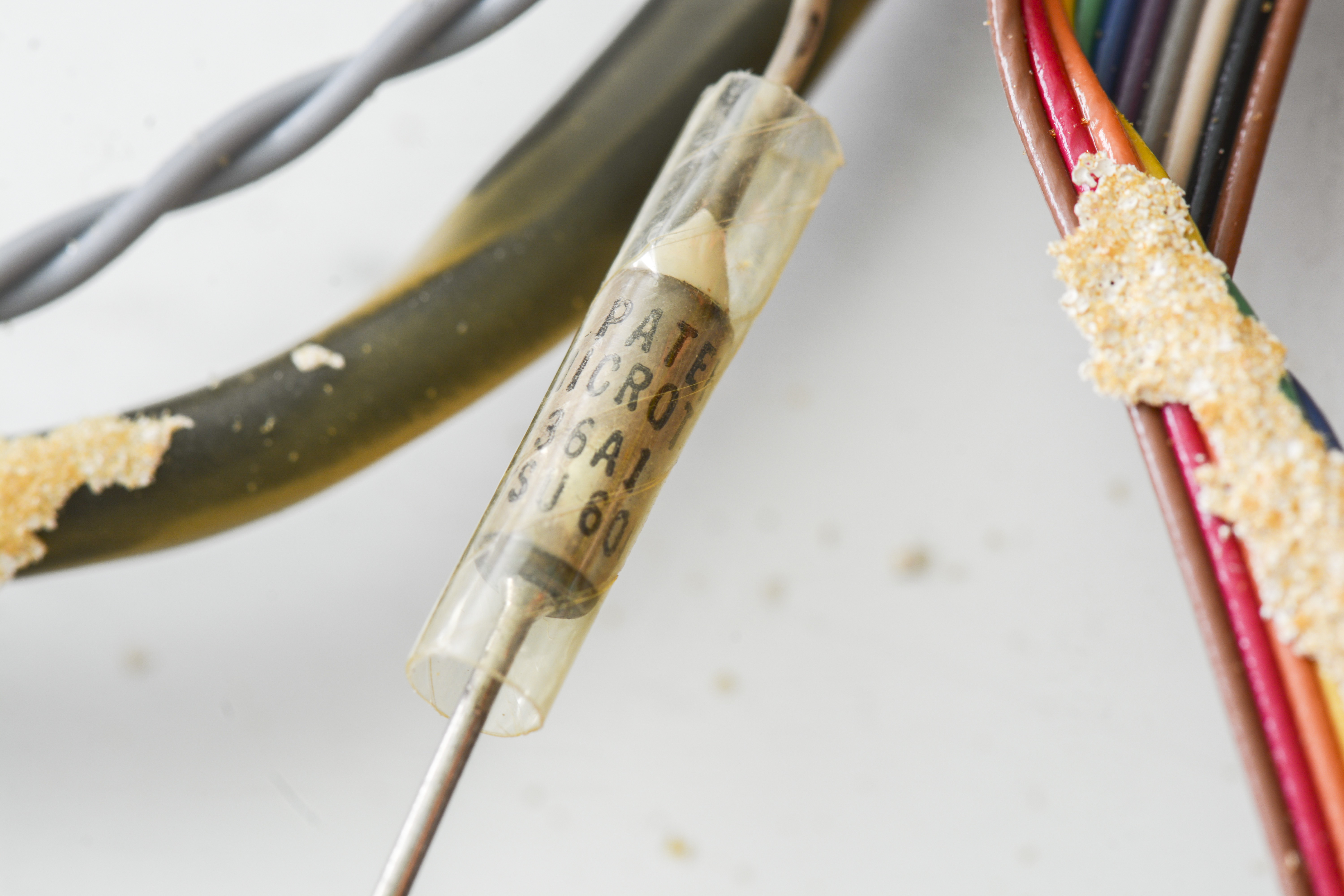
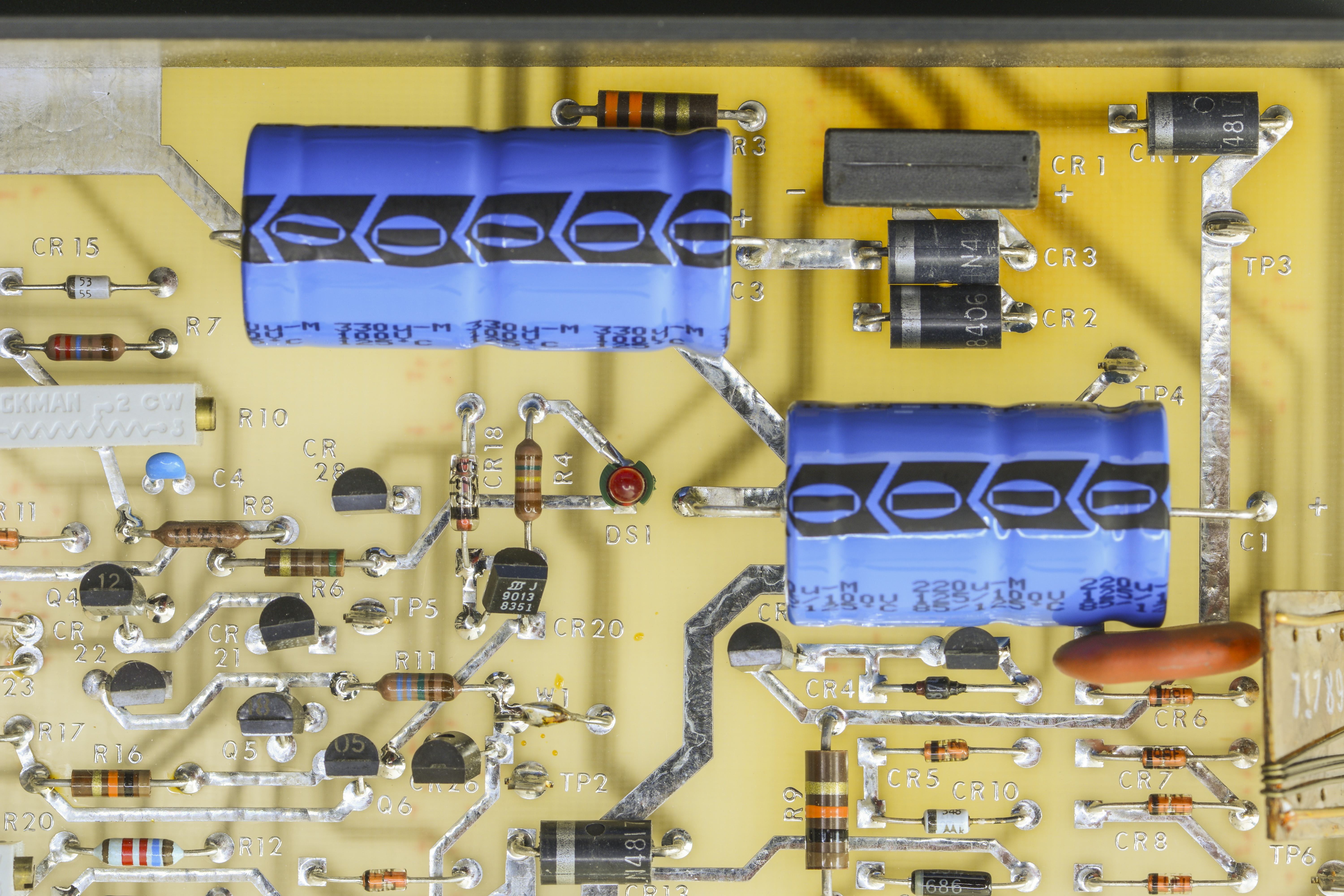
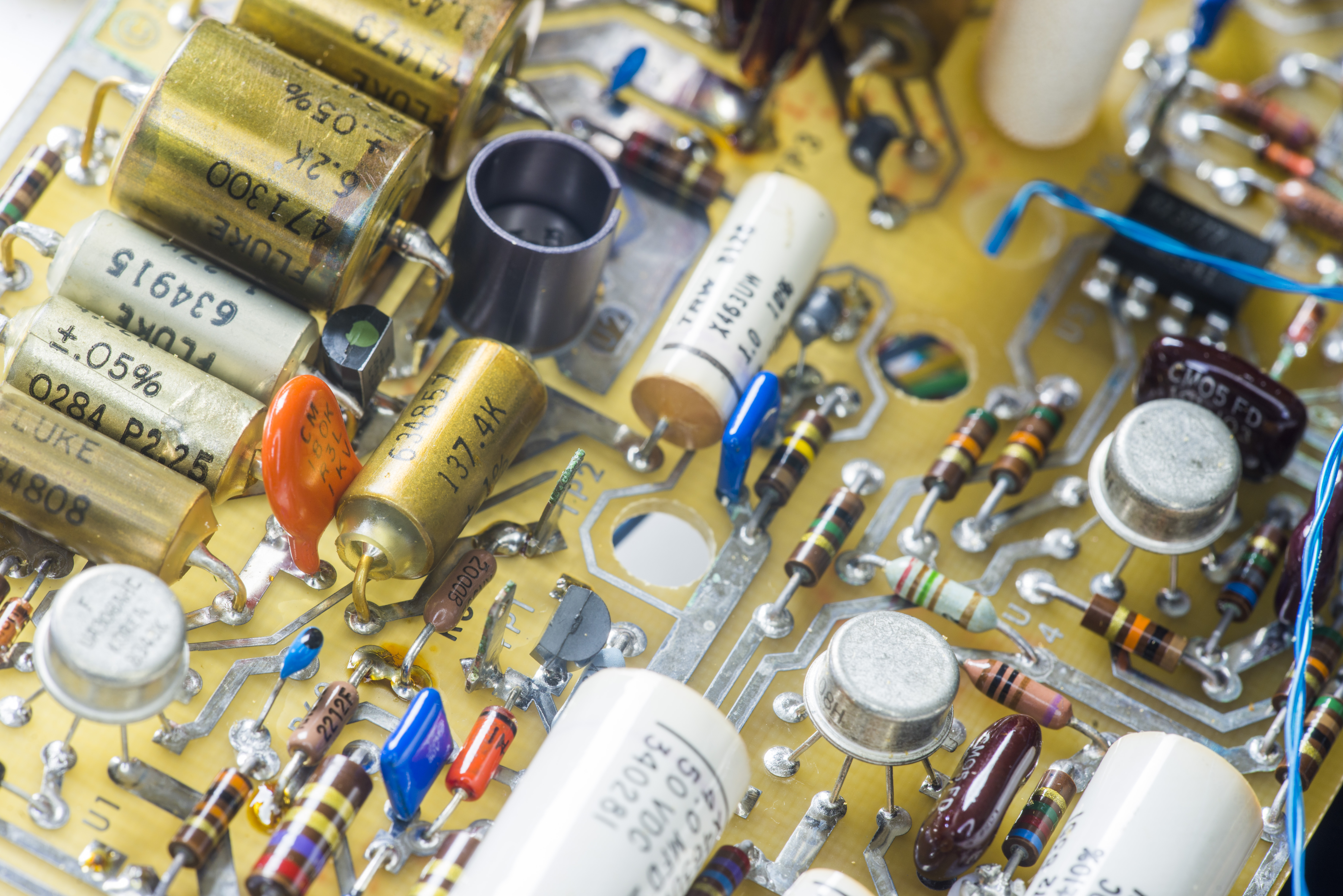
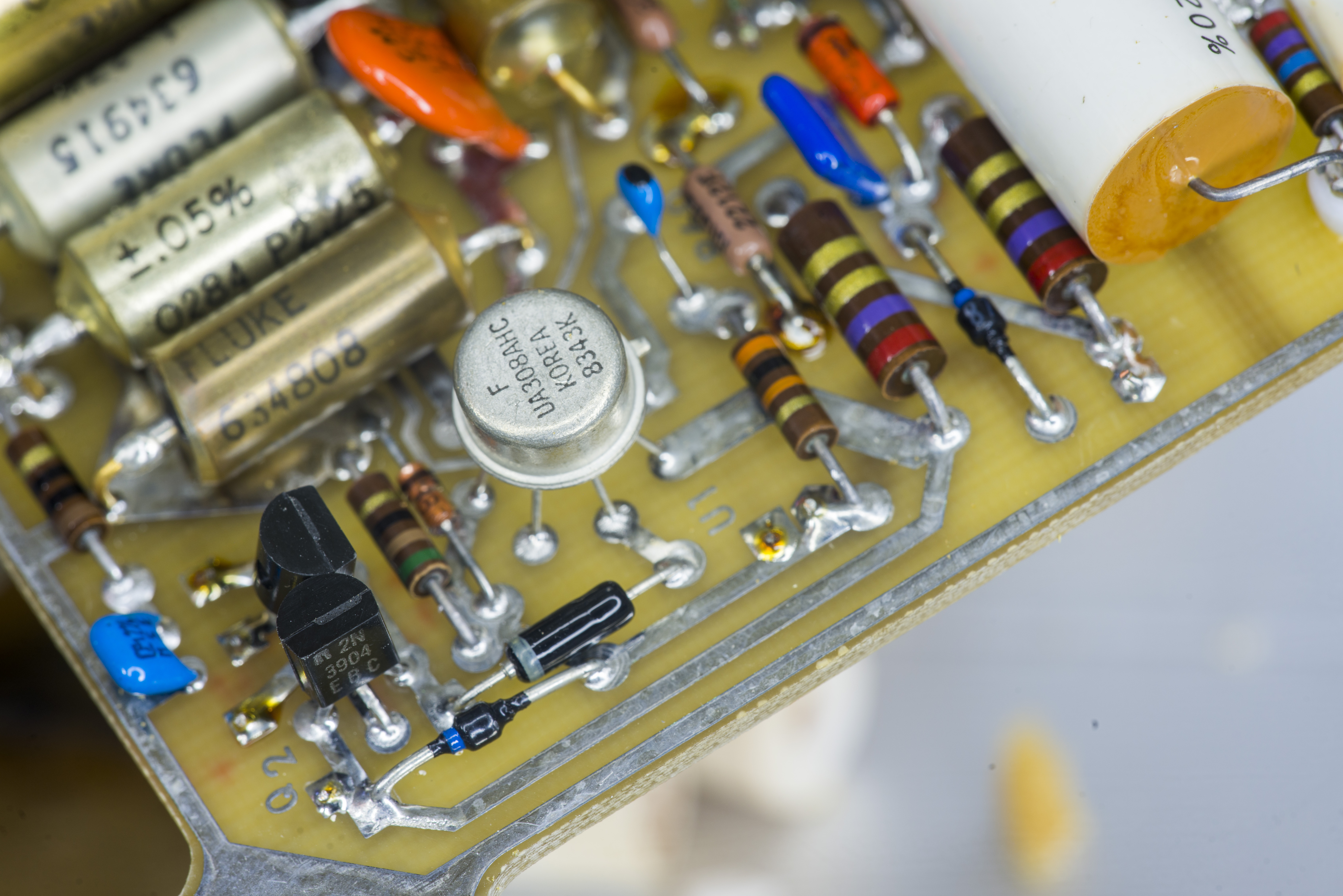
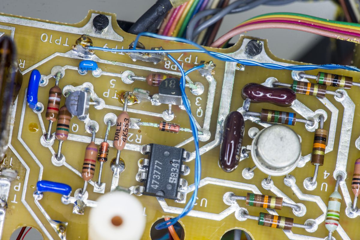
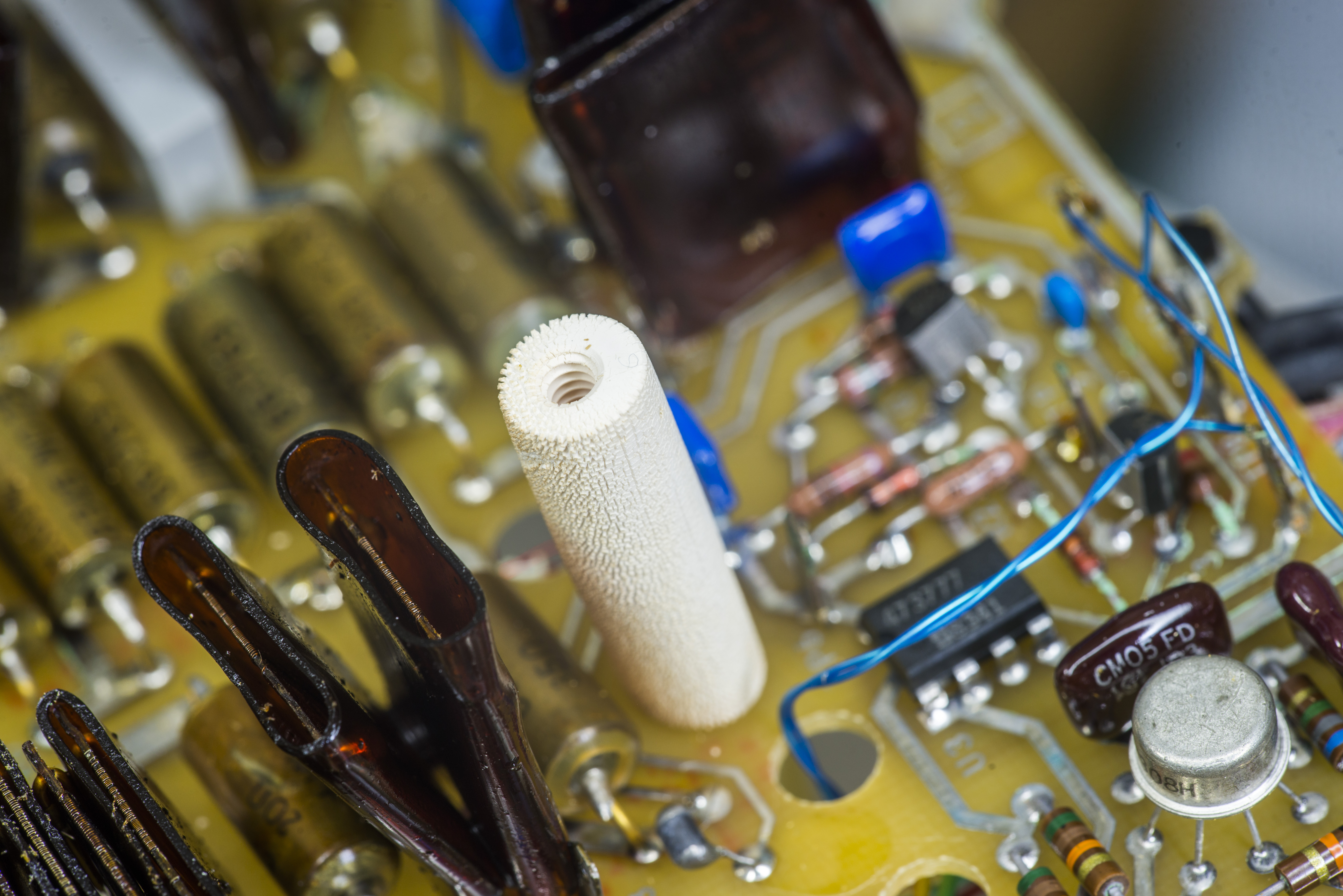
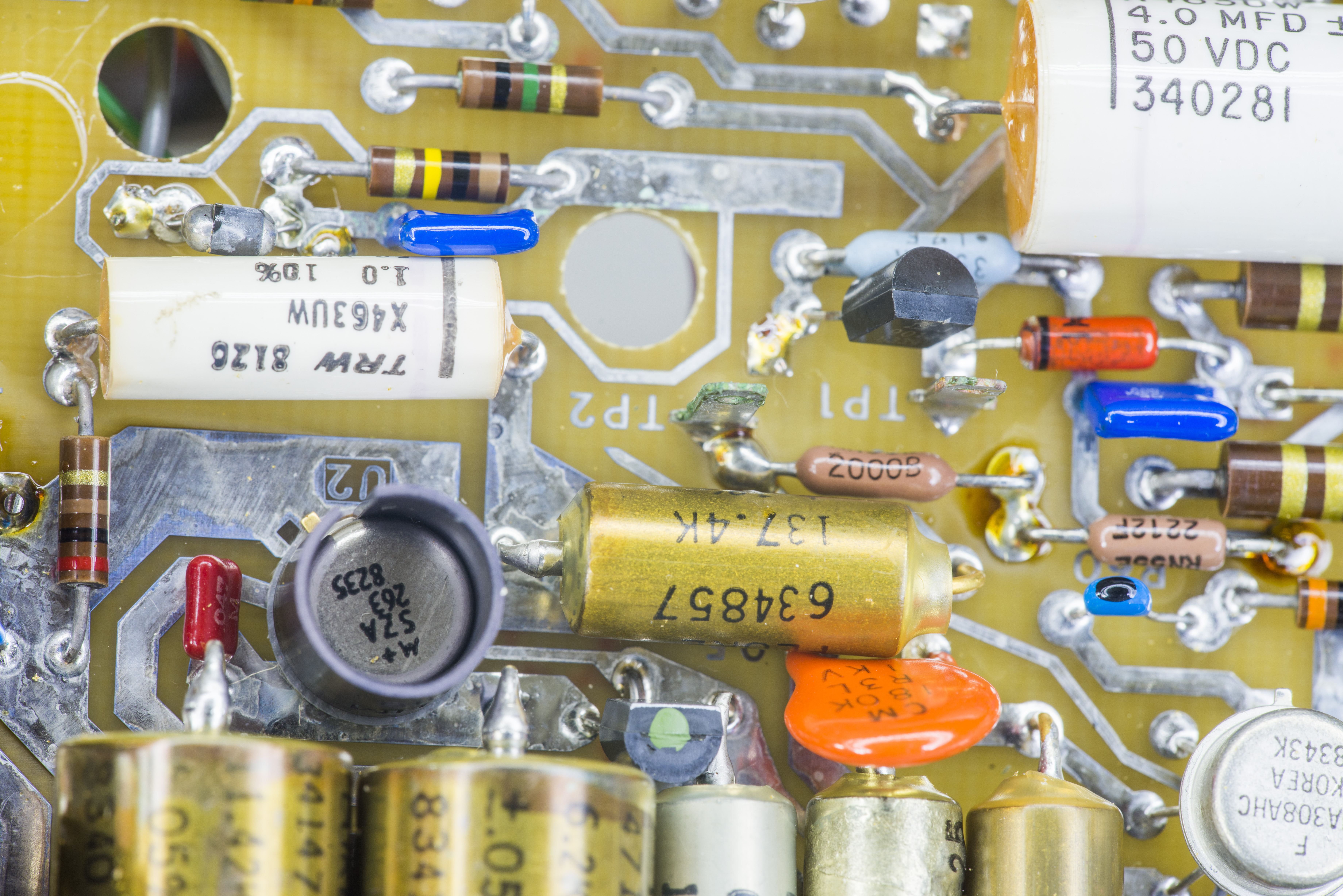
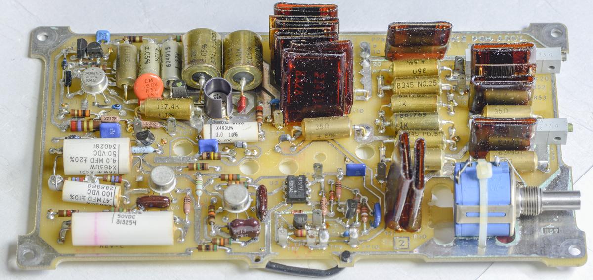
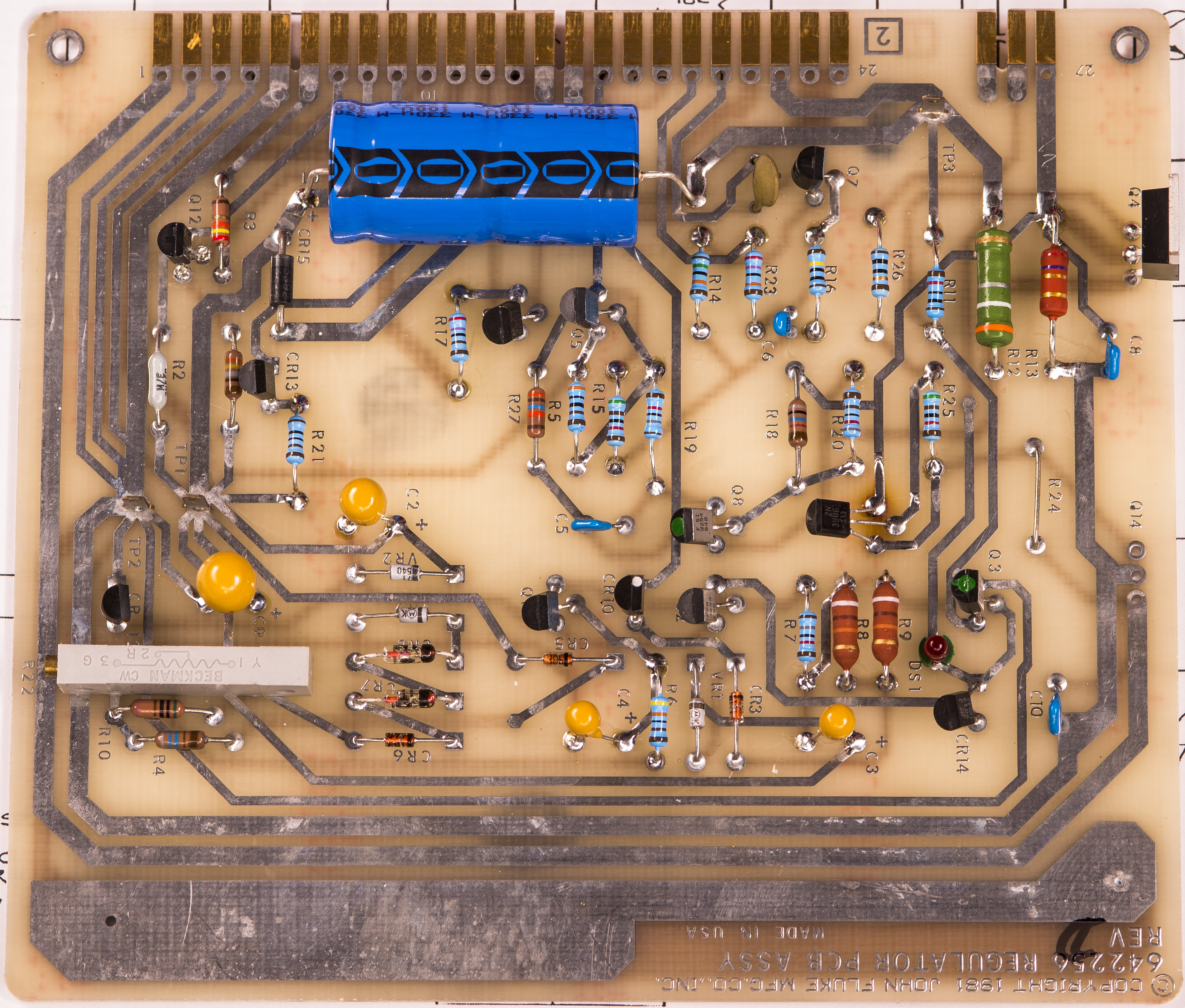
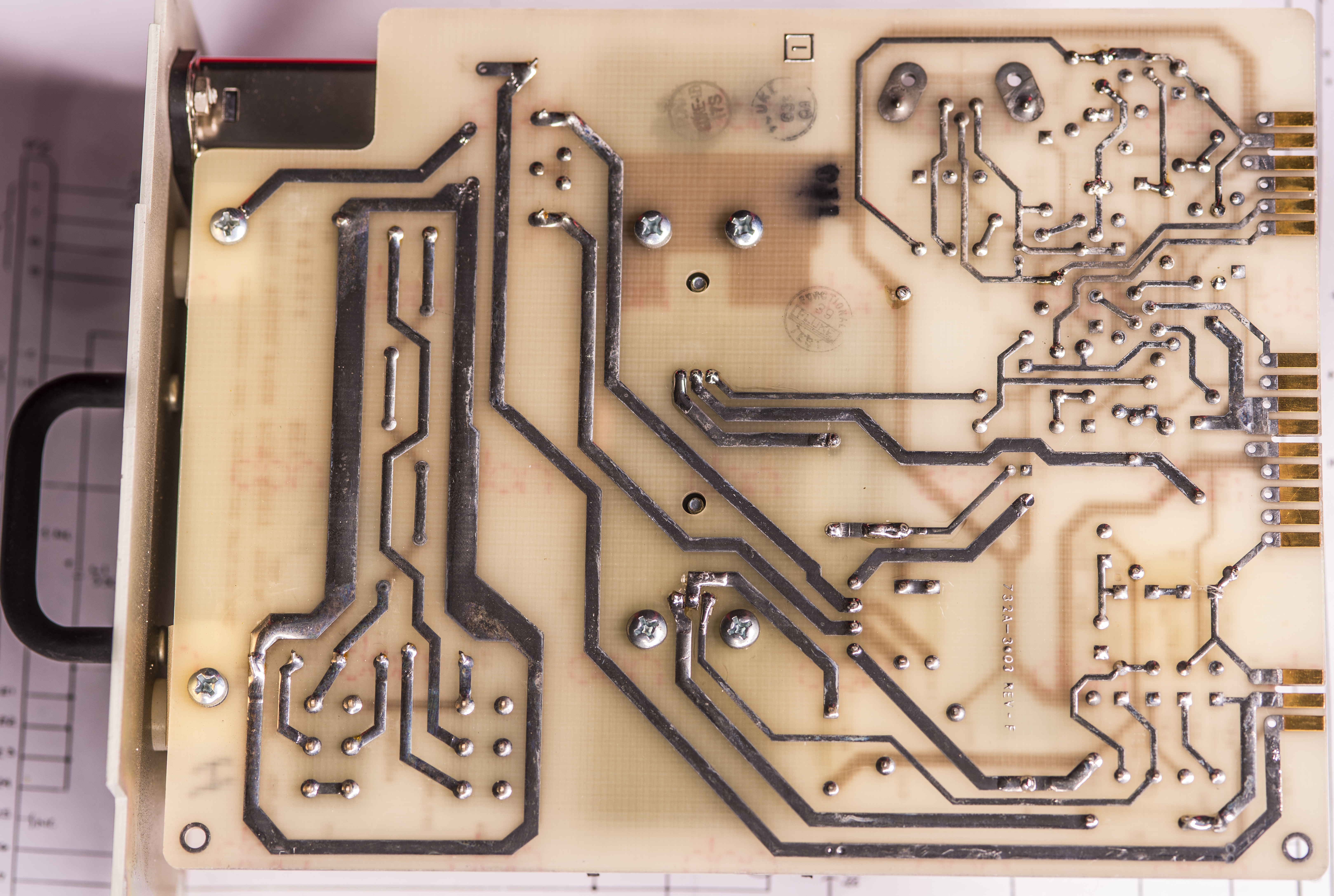
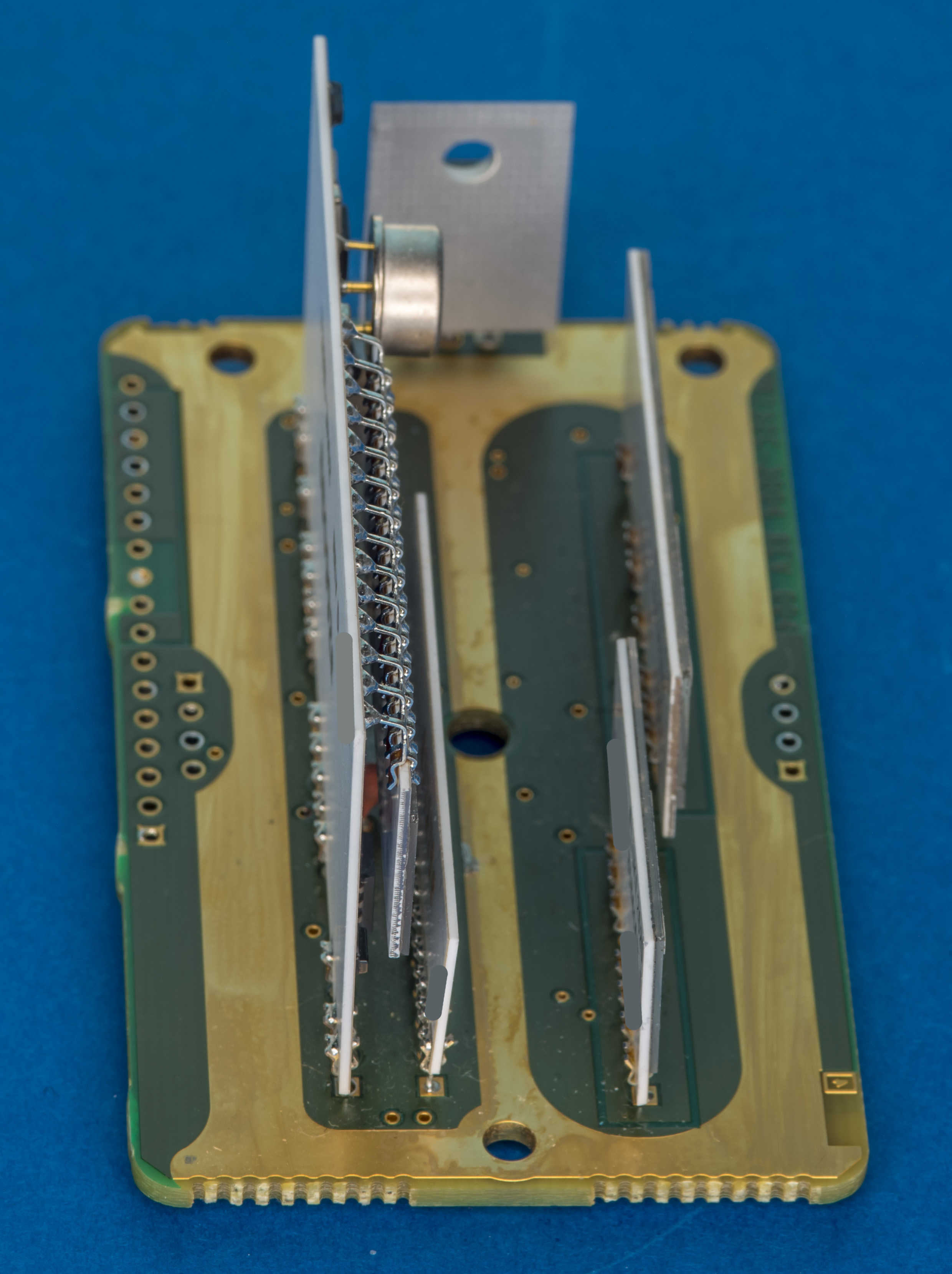
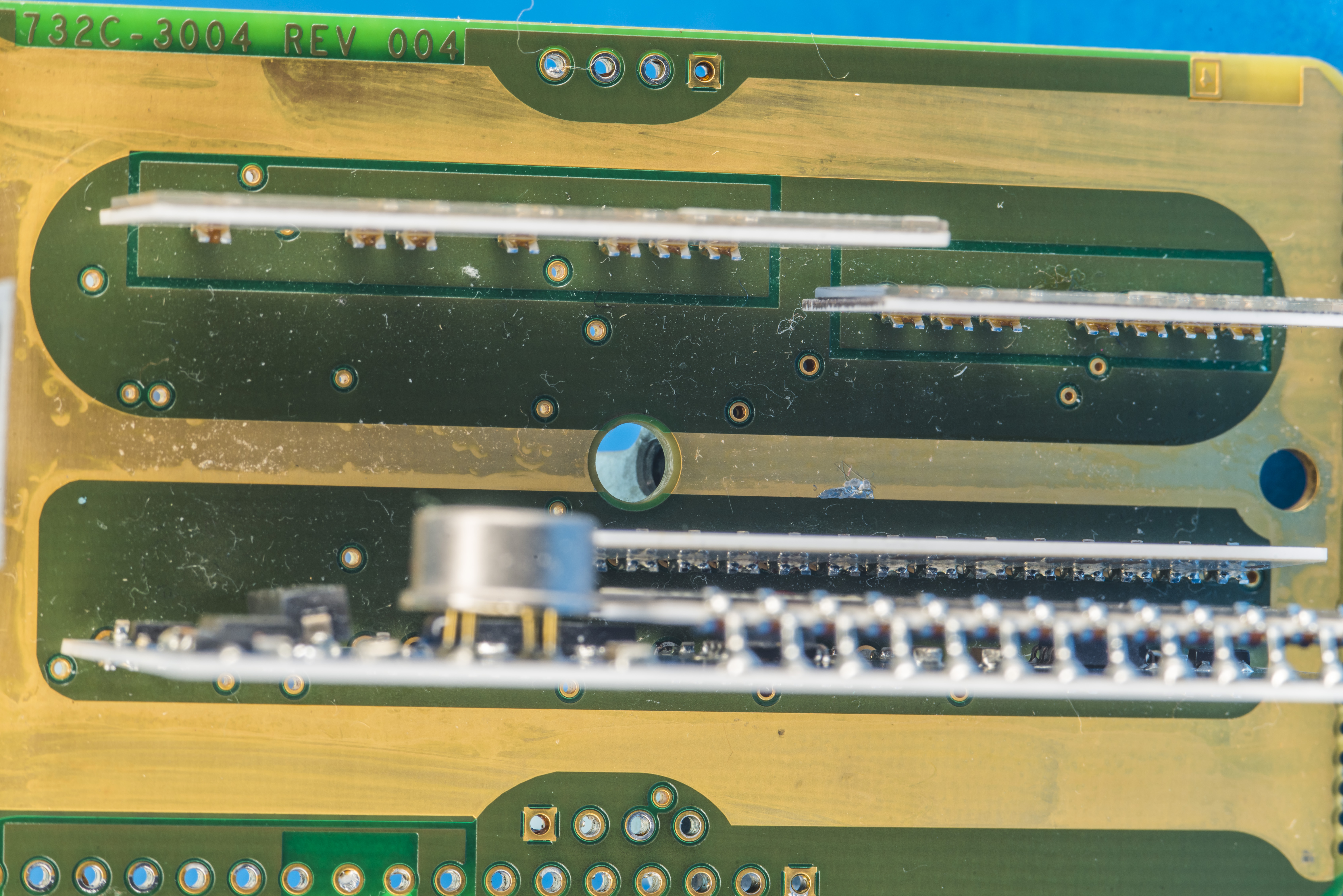
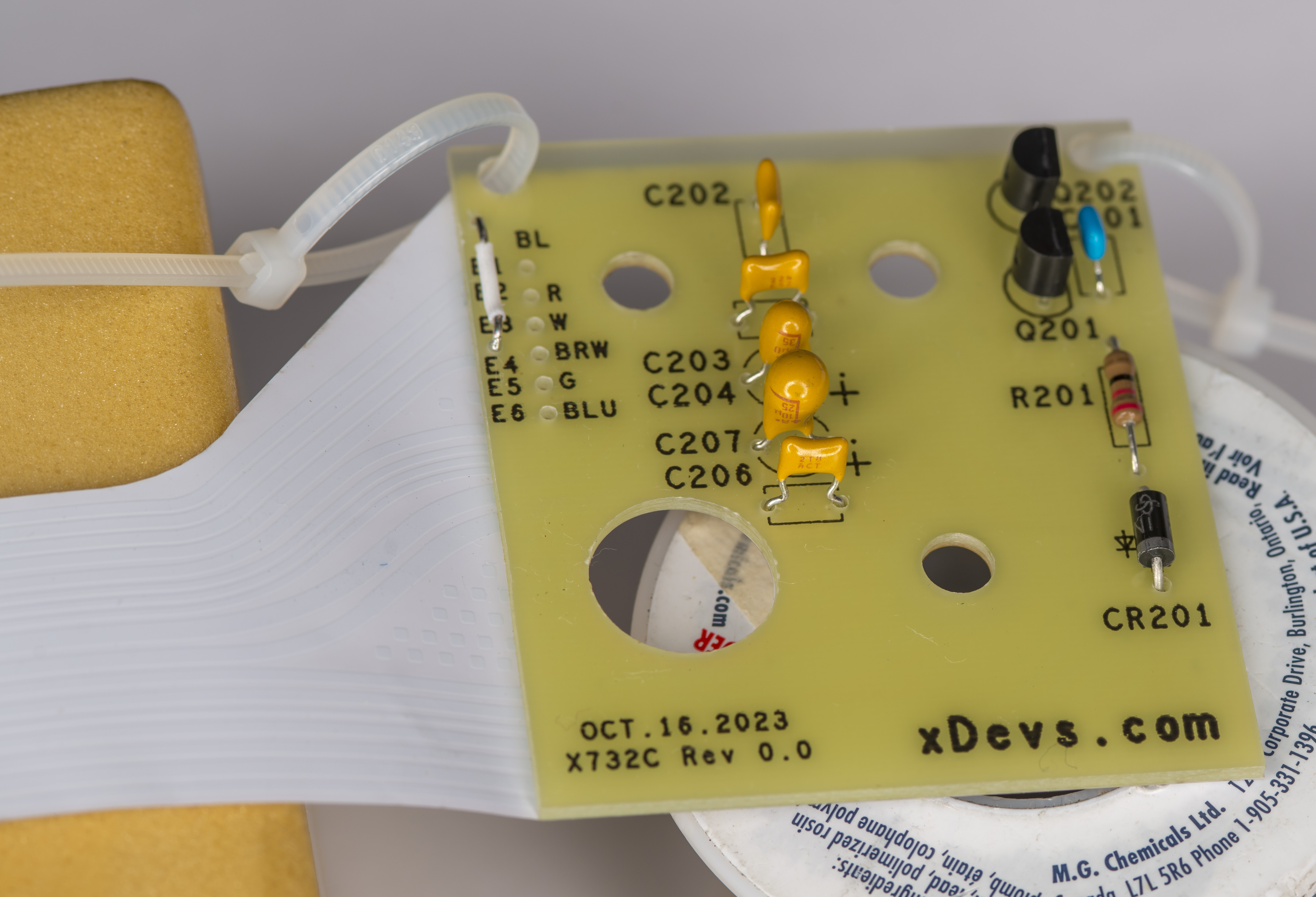
I have also captured some see-through images of the A4 PCBA to confirm the resistor construction.
Image 9: Transparent image of the components and A4 PCBA, top section
Can clearly see different design in thin-film or metal film resistors and carbon composite ones on these images.
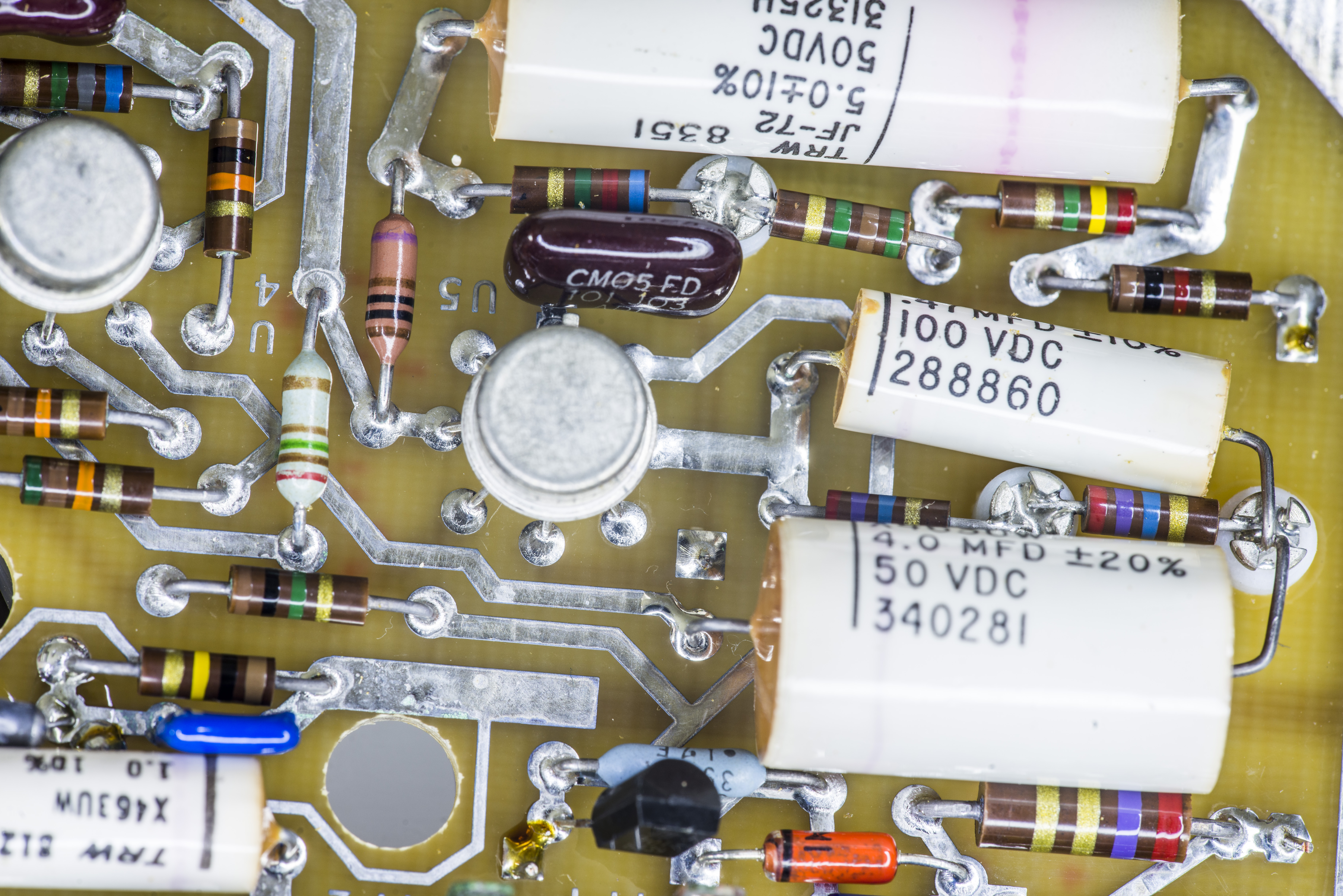
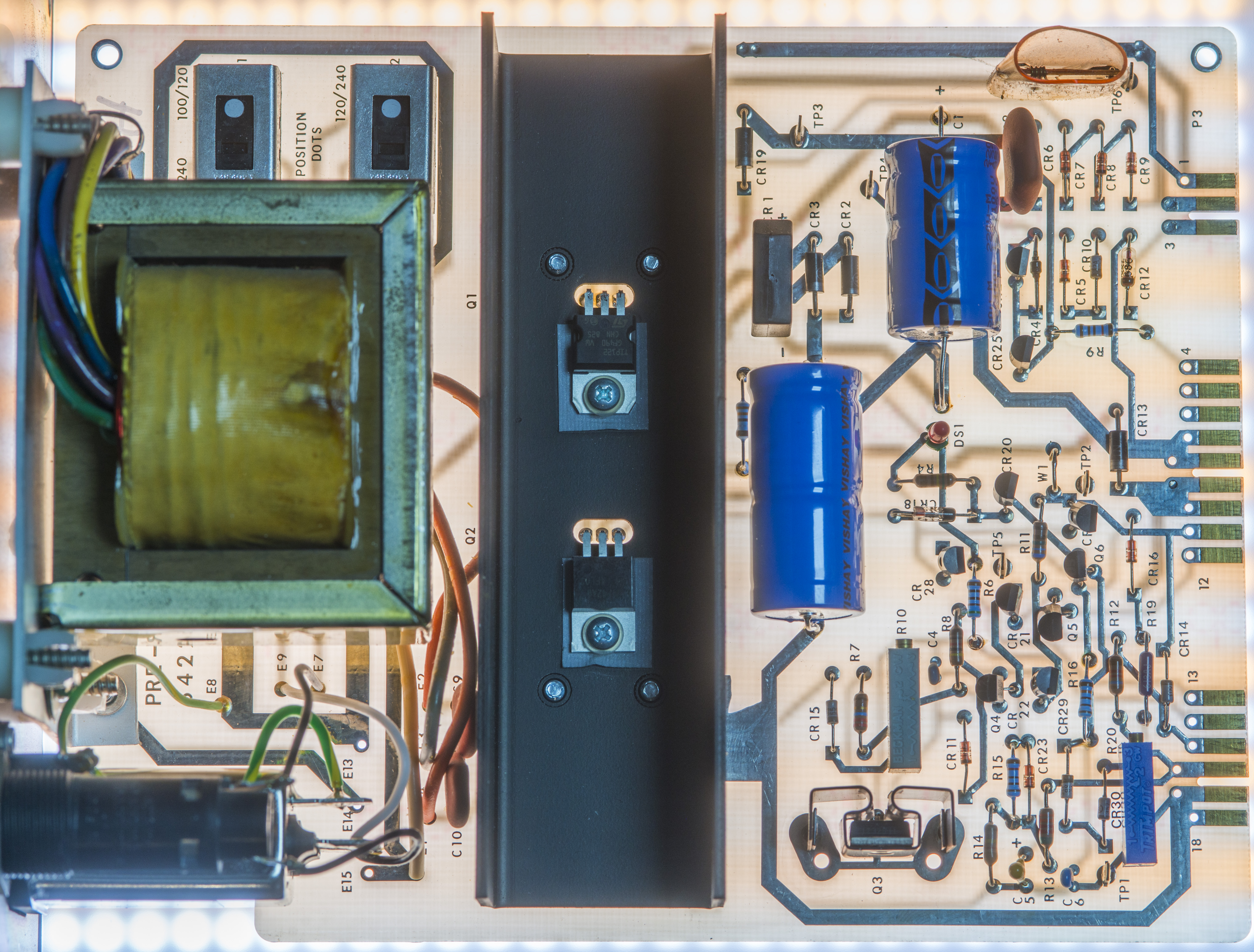
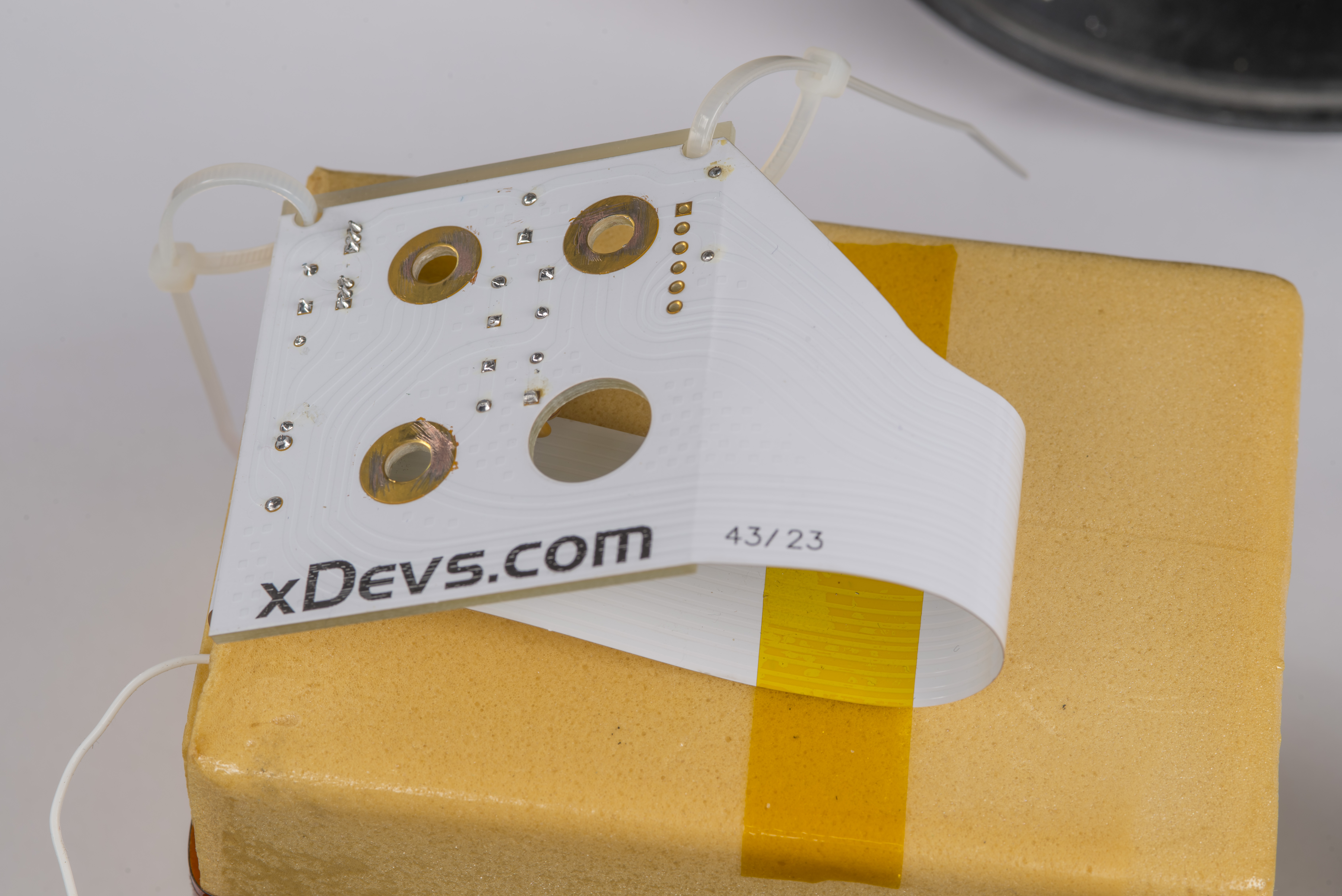
Image 10: Transparent image of the components and A4 PCBA, bottom section
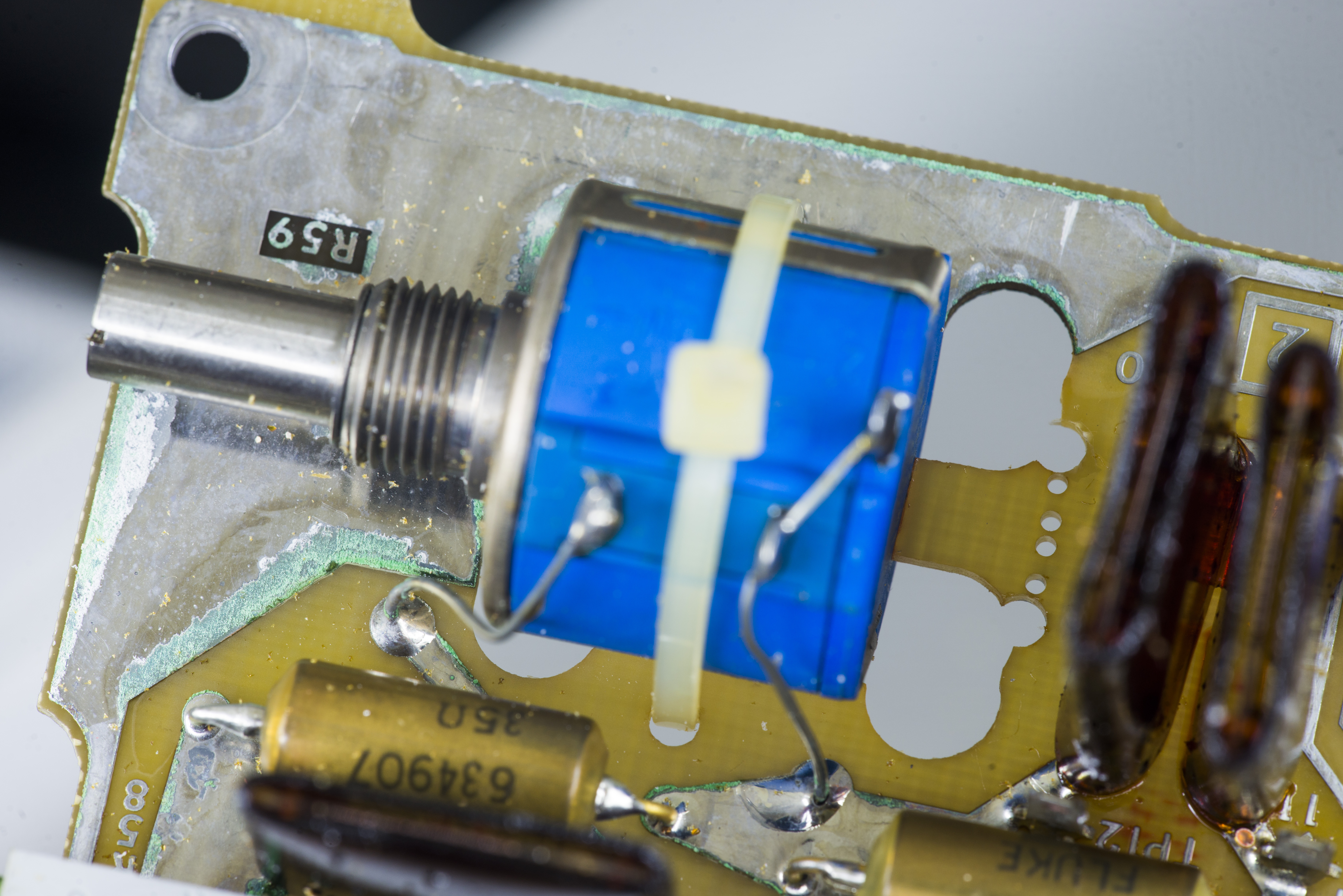
One of the larger resistors that looks outside like a typical carbon composite actually a low-ohm wire-wound. There is no need to replace that one :)
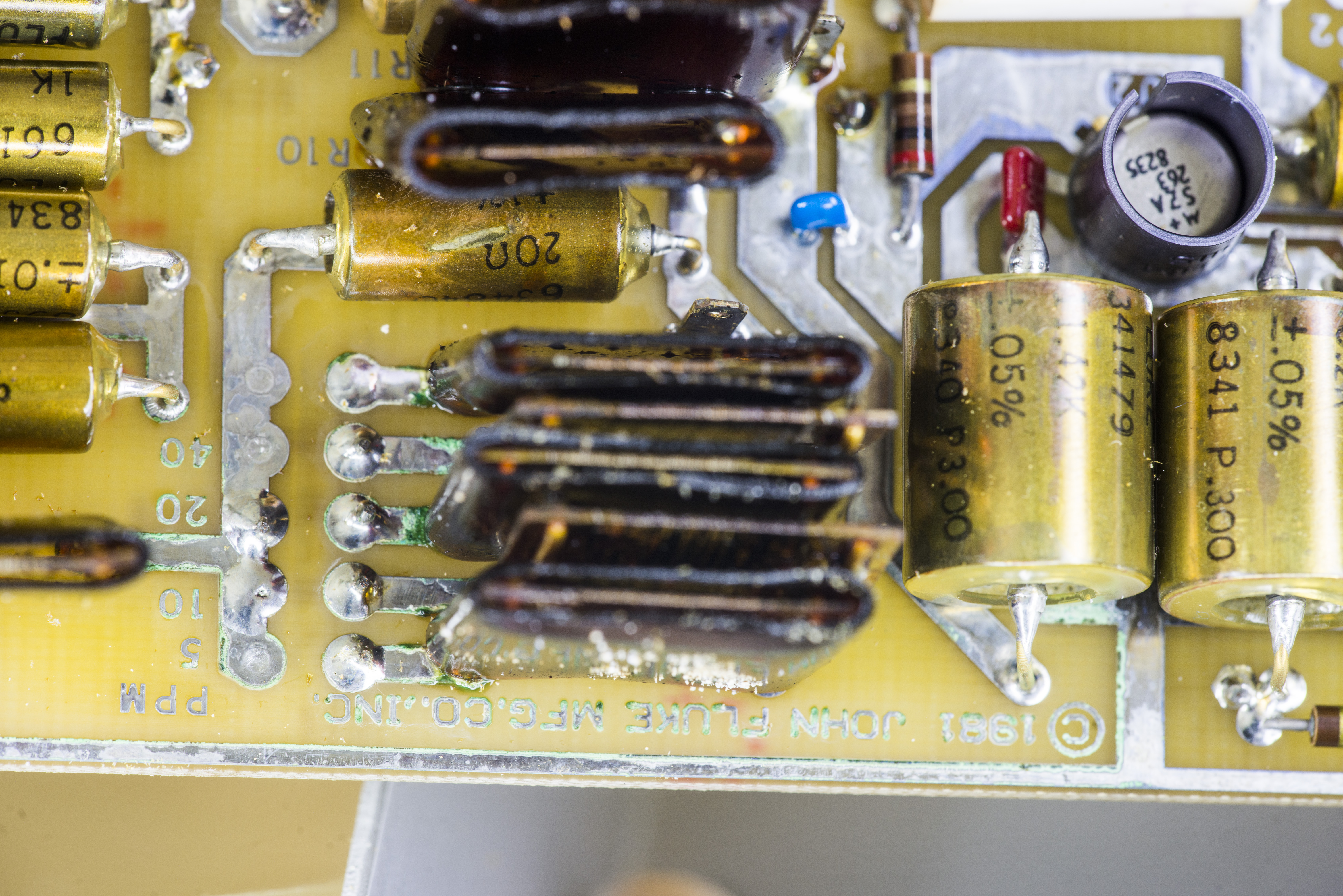
Image 11: Dimensional transparent image of the A4 transistor and resistors
Easy to spot different terminal contact methods for different resistors.
Parts replacements
A quick photograph during the replacement process. Most of the parts I already had in stock at xDevs lab from previous 732A repairs, but few I had to order again. I like to use Digikey for common parts since they have nice GUI and powerful search. This is especially useful since number of parts in 732A are already obsoleted such as 2N6125 PNP power transistor. I’ve replaced these with TIP42 which has comparable specifications.
Image 12: Parts replacement progress, first few hours
After mains filter, caps and resistors replacement done here are the updated photos of A3 board:
Image 13: A3 with new parts
Back of the PCB was cleaned up with 99% isopropyl alcohol after reworks.
Image 14: A3 with new parts, bottom side
Small tantalum 1 µF capacitor was replaced with SMT version as I didn’t buy a leaded version. It would work just fine in this application.
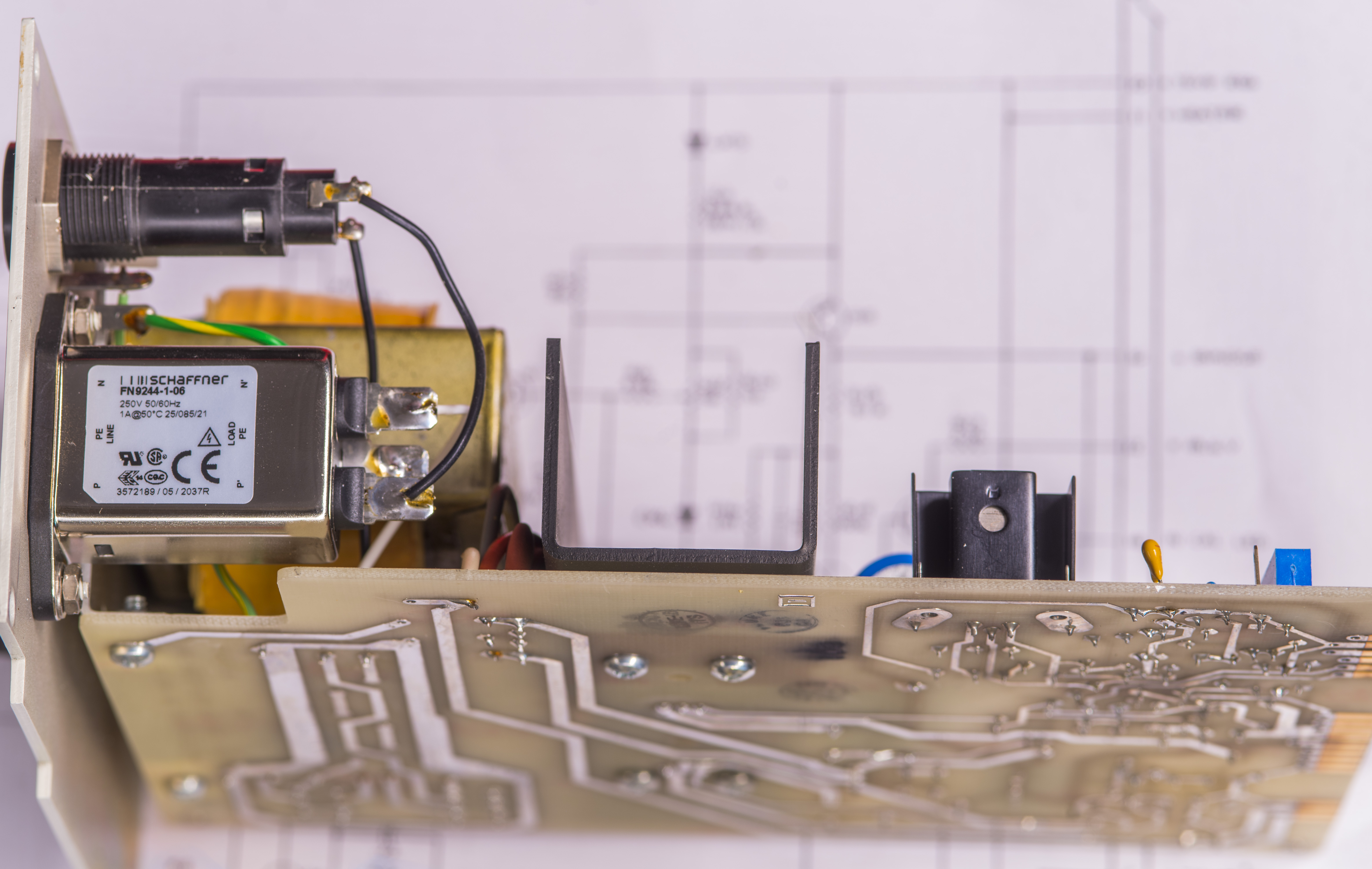
Image 15: Replaced mains entry filter

Image 16: Top view on A3 pre-regulator PCBA
And A4 board images below with had much more carbon composite resistors swapped out.
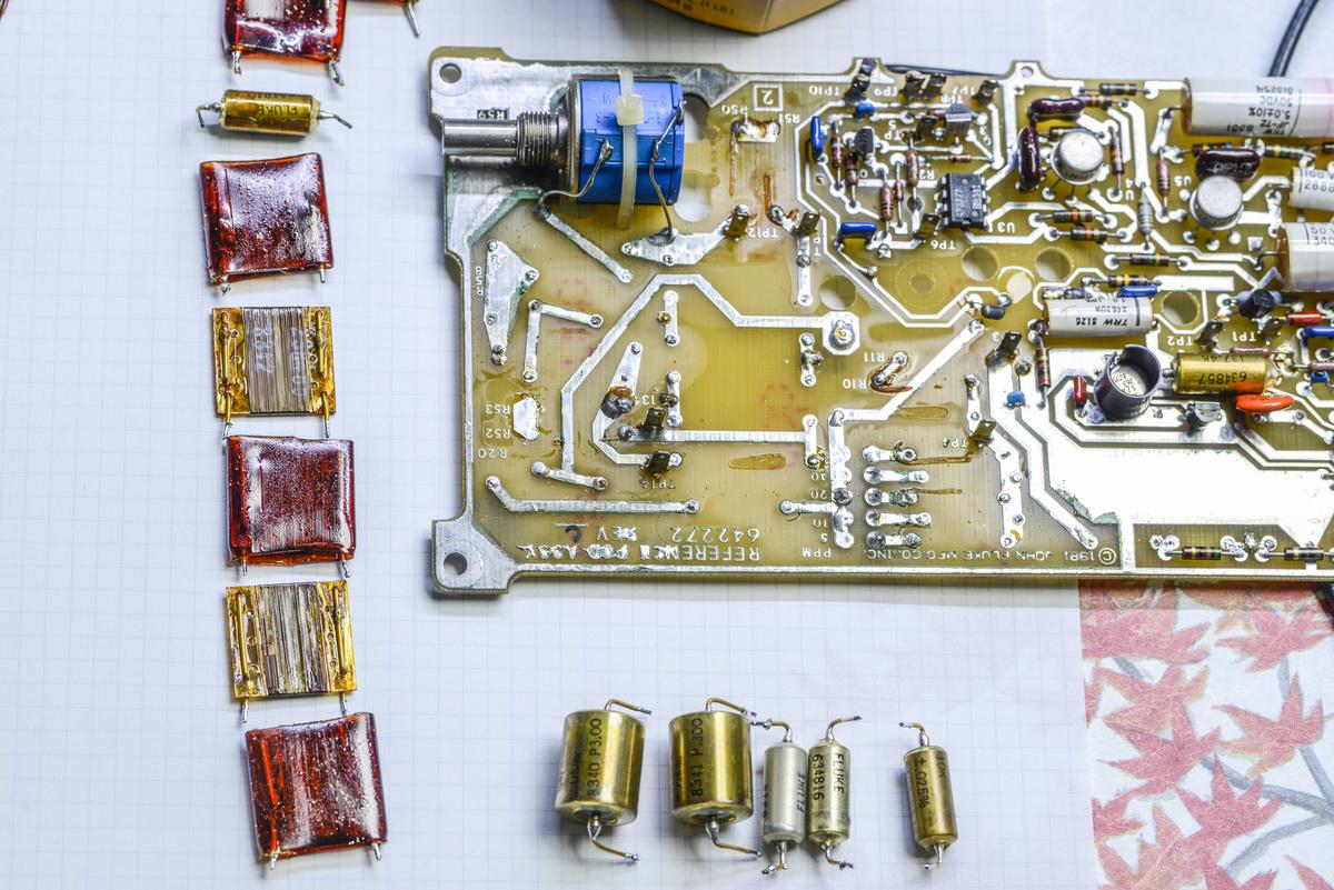
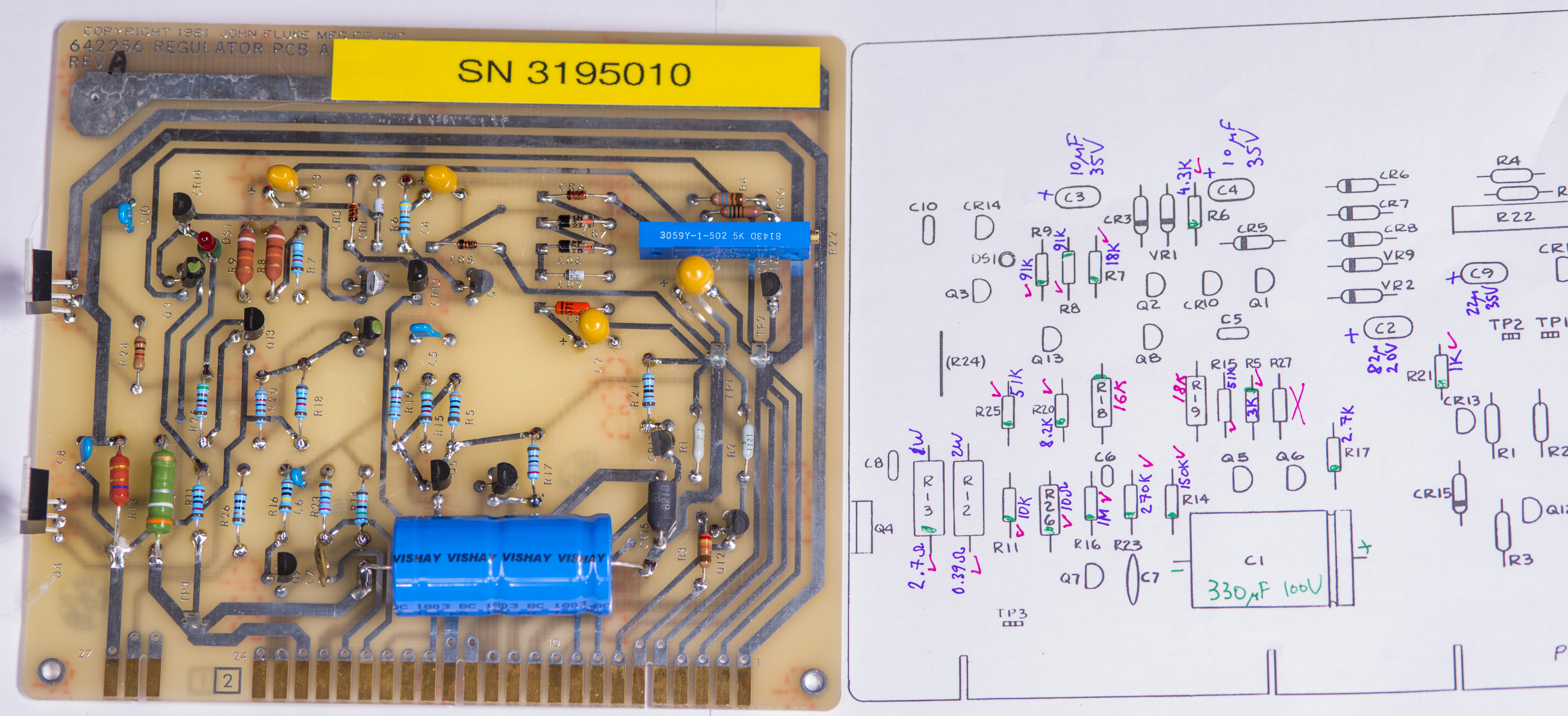
Image 17: Frontal image of the board, serviced
I’ve consulted with the latest instruction manual to double check the resistor values as well.
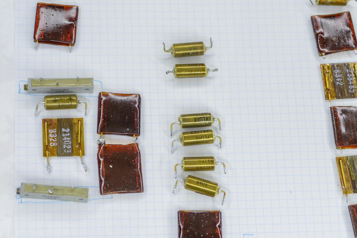
Image 18: Capacitors and parts
Spot measurements on few of the resistors revealed that they were +30% higher than nominal.
Image 19: Tantalum caps together
Tantalum capacitors were double checked to make sure the polarity and pin orientation is correct. Otherwise overheating, fire and damage to PCB is highly possible.
Image 20: Lone resistor on the back, kept original
Battery pack information
Battery pack was already reassembled by the owner of the unit and here just documented result. Batteries have date code from year 2022. Elements used in this pack were EnerSys Genesis NP5-6. These are 6 V 5 Ah VRLAs and have sweet spot stand-by voltage at 6.83 V or 27.3 V total in series array. They are rated for four years of float service life until capacity drops below 60%, typical numbers for VRLA battery pack.
BOM list of parts used in this 732A repair
Here’s the complete BOM list of components used in servicing this 40 year old Fluke 732A standard. I like to get some extra parts when they are cheap to stockpile for future in case I’ll need to repeat the project later. This approach saved me multiple times when part got obsoleted and not available to buy anymore but I still had some new old stock. Especially some classes like axial capacitors or old high-speed transistors are getting hard to acquire these days. Plus we often can get a price break for getting more parts.
| Quantity | Component description | Vendor and partnumber | Digikey SKU | Price, USD (October 2024) |
|---|---|---|---|---|
| 4 | Battery AGM, 6V 5Ah 70 × 47 × 105 mm | EnerSys Genesis NP Series NP5-6 | Not digikey part | 105 |
| 1 | Power Entry Connector Receptacle, Male Blades IEC 320-C14 Panel Mount, Flange | SCHURTER Inc. 5110.0133.1 | 486-1038-ND | 17.92 |
| 5 | Shoulder Washer 0.040” (1.02mm) Thick Polyphenylene Sulfide, Glass Filled | Boyd Laconia, LLC 7721-8PPSG | 7721-8PPSG-ND | 4.48 |
| 1 | Bipolar (BJT) Transistor NPN 120 V 8 A 30MHz 50 W Through Hole TO-220 | onsemi MJE15028G | MJE15028GOS-ND | 1.65 |
| 2 | Bipolar (BJT) Transistor PNP 60 V 6 A 3MHz 2 W Through Hole TO-220 | onsemi TIP42AG | TIP42AGOS | 2.58 |
| 10 | Bipolar (BJT) Transistor NPN – Darlington 60 V 5 A 2 W Through Hole TO-220 | onsemi TIP120G | TIP120GOS-ND | 8.70 |
| 10 | 330 µF 100 V Aluminum Electrolytic Capacitors Axial, Can 120mOhm 8000 Hrs 125°C | Vishay MAL212019331E3 | 4538PHBK-ND | 63.14 |
| 10 | 220 µF 100 V Aluminum Electrolytic Capacitors Axial, Can 660mOhm 8000 Hrs 125°C | Vishay MAL211819221E3 | 4171PHBK-ND | 58.96 |
| 10 | 1 µF Molded Tantalum Capacitors 50 V 2312 (6032 Metric) 5.5Ohm | Kyocera AVX TAJC105M050RNJ | 478-3894-1 | 6.86 |
| 10 | CAP TANT 10 µF 10% 50V RADIAL | Kyocera AVX TAP106K050CRW | 478-TAP106K050CRWCT-ND | 12.96 |
| 10 | CAP TANT 22 µF 10% 50V RADIAL | Kyocera AVX TAP226K050CCS | 478-1879-ND | 56.88 |
| 10 | CAP TANT 100 µF 10% 20V RADIAL | Kyocera AVX TAP107K020CRW | 478-7369-1-ND | 18.75 |
| 10 | Resistor, 510 Ω ±1% 0.6W Through Hole Resistor Axial Metal Film | TE LR1F510R | 1712-LR1F510RCT-ND | 0.54 |
| 10 | Resistor, 100 kΩ ±1% 0.6W Through Hole Resistor Axial Metal Film | TE LR1F100K | A105945CT-ND | 0.54 |
| 10 | Resistor, 91 kΩ 5% 2W AXIAL | TE RR02J91KTB | A138369CT | 1.74 |
| 10 | Resistor, 18 kΩ 0.6W 1% AXIAL | Vishay MBB02070C1802FCT00 | BC3640CT-ND | 1.2 |
| 10 | Resistor, 1 MΩ 0.6W 1% AXIAL | Vishay MBB02070C1004FCT00 | BC3573CT-ND | 1.17 |
| 10 | Resistor, 16 kΩ 1% 0.6W AXIAL | Vishay MBB02070C1602FCT00 | BC4451CT-ND | 3.09 |
| 10 | Resistor, 3.3 Ω 0.6W 1% AXIAL | Vishay MBB02070C3308FCT00 | BC3750CT-ND | 1.29 |
| 10 | Resistor, 10 Ω 0.6W 1% AXIAL | Vishay MBB02070C1009FCT00 | BC3580CT | 1.2 |
| 10 | Resistor, 4.3 kΩ 1% 0.6W AXIAL | Vishay MBB02070C4301FCT00 | BC4474CT | 3.09 |
| 10 | Resistor, 3 kΩ 1% 0.6W AXIAL | Vishay MBB02070C3001FCT00 | BC4461CT-ND | 3.09 |
| 10 | Resistor, 2.7 kΩ 0.6W 1% AXIAL | Vishay MBB02070C2701FCT00 | BC3711CT | 1.2 |
| 10 | Resistor, 8.2 kΩ 0.6W 1% AXIAL | Vishay MBB02070C8201FCT00 | BC3891CT | 1.2 |
| 10 | Resistor, 270 kΩ 0.6W 1% AXIAL | Vishay MBB02070C2703FCT00 | BC3715CT | 1.19 |
| 10 | Resistor, 51 kΩ 0.6W 1% AXIAL | Vishay MBB02070C5102FC100 | BC3822CT | 3.57 |
| 10 | Resistor, 150 kΩ 0.6W 1% AXIAL | Vishay MBB02070C1503FCT00 | BC3620CT | 1.2 |
Table 1: Component list for Fluke 732A DC standard repairs
Total cost to refurbish 732A (with some extra parts left over for future projects) was approximately $400 USD including shipping. If no extra parts to be ordered this cost could probably optimize down to $250 USD or so. Parts replacement process took about 5 hours from start to finish, pretty doable in a weekend time.
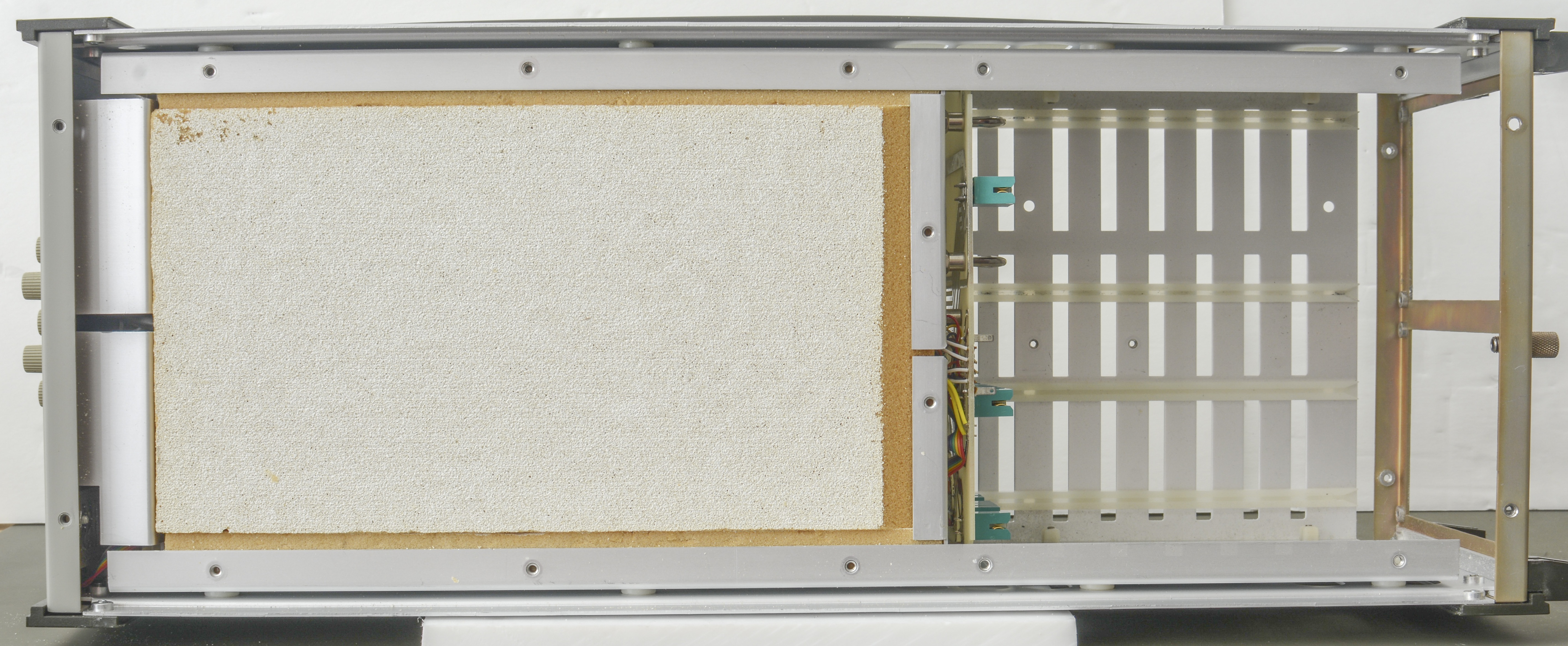
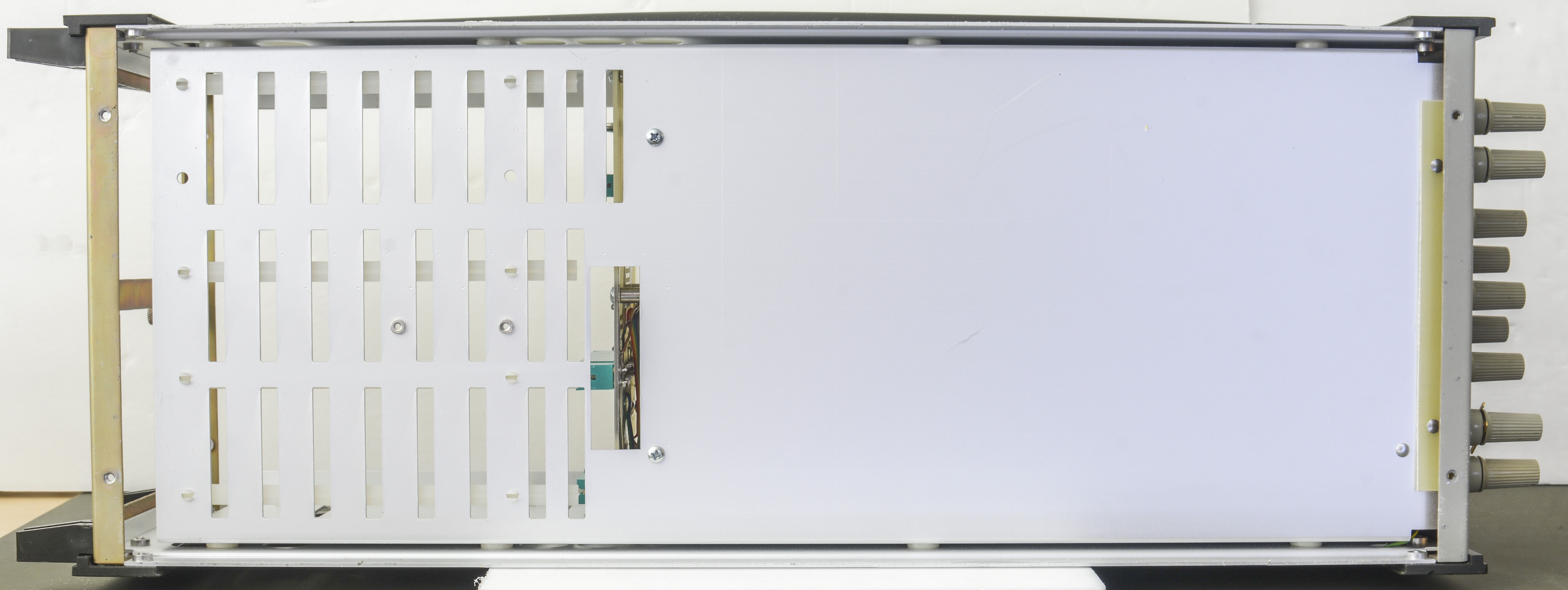
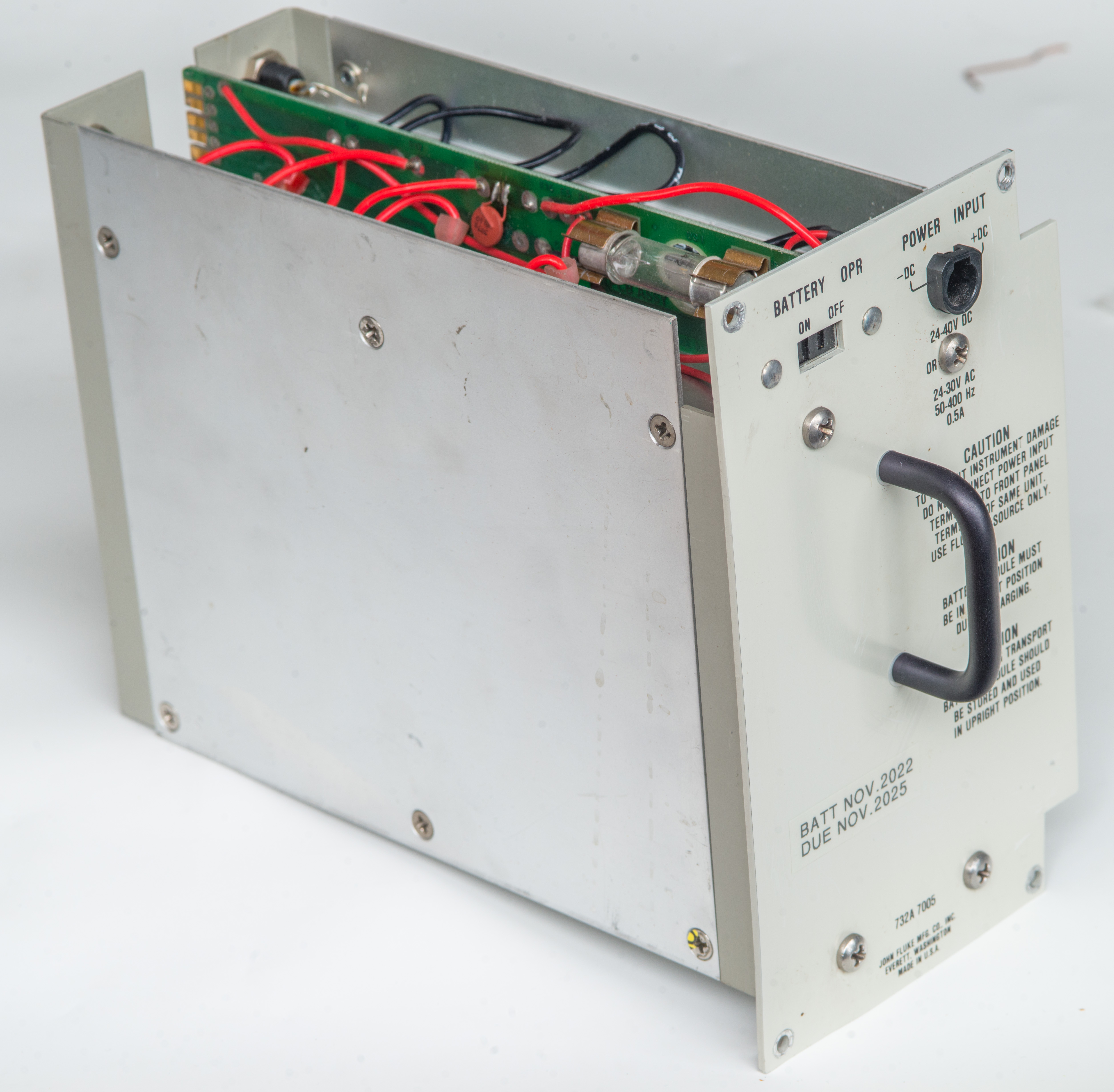
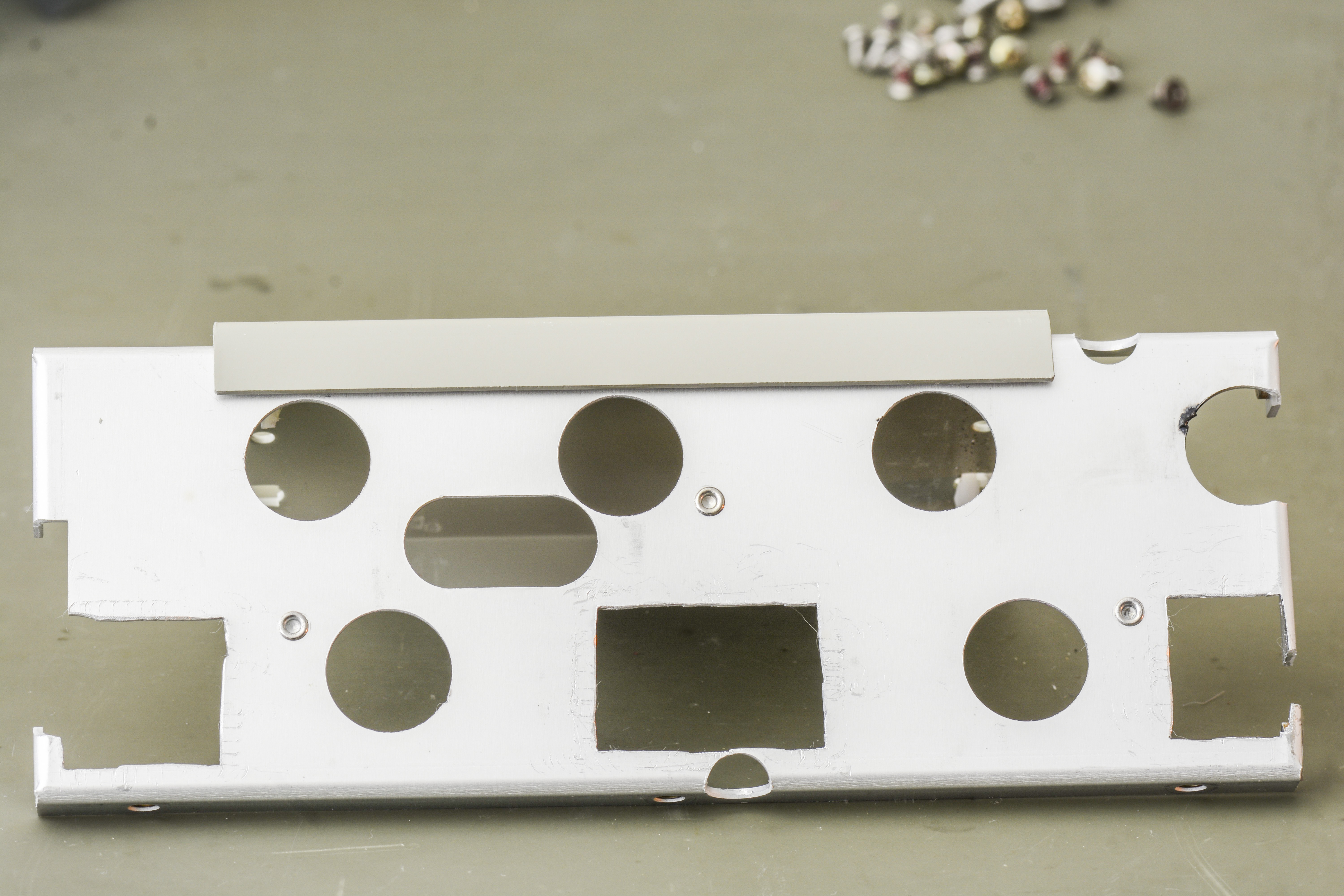
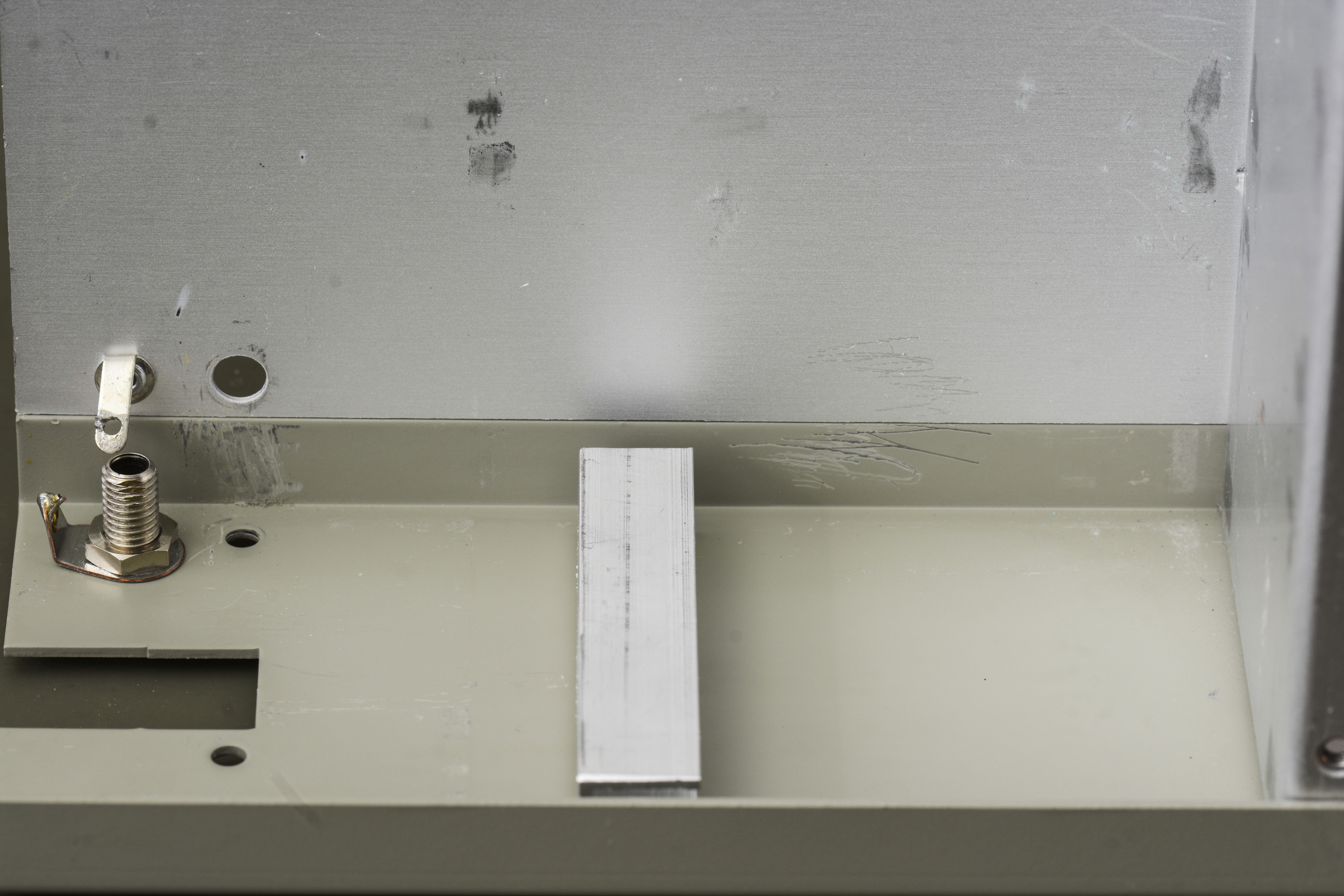
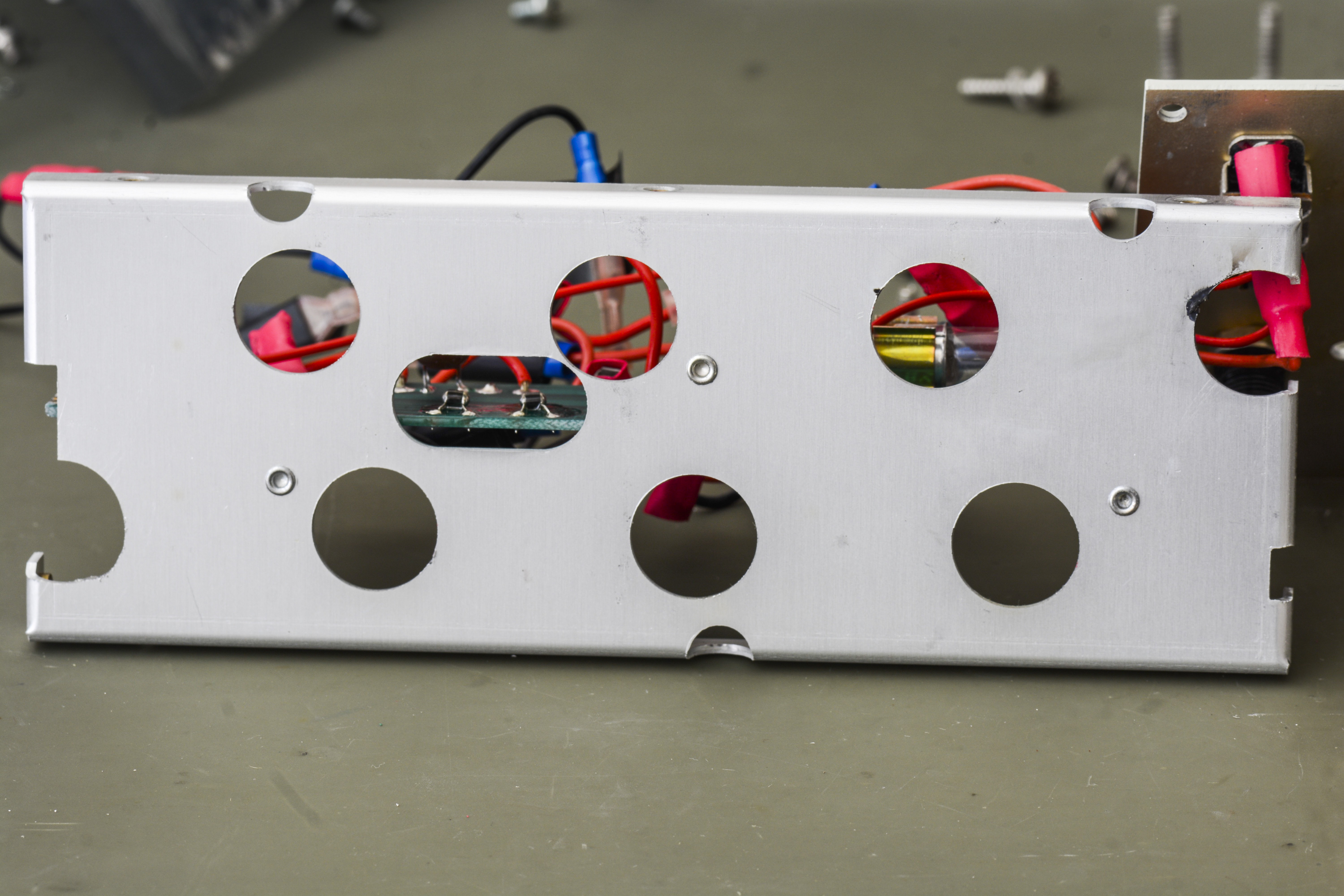
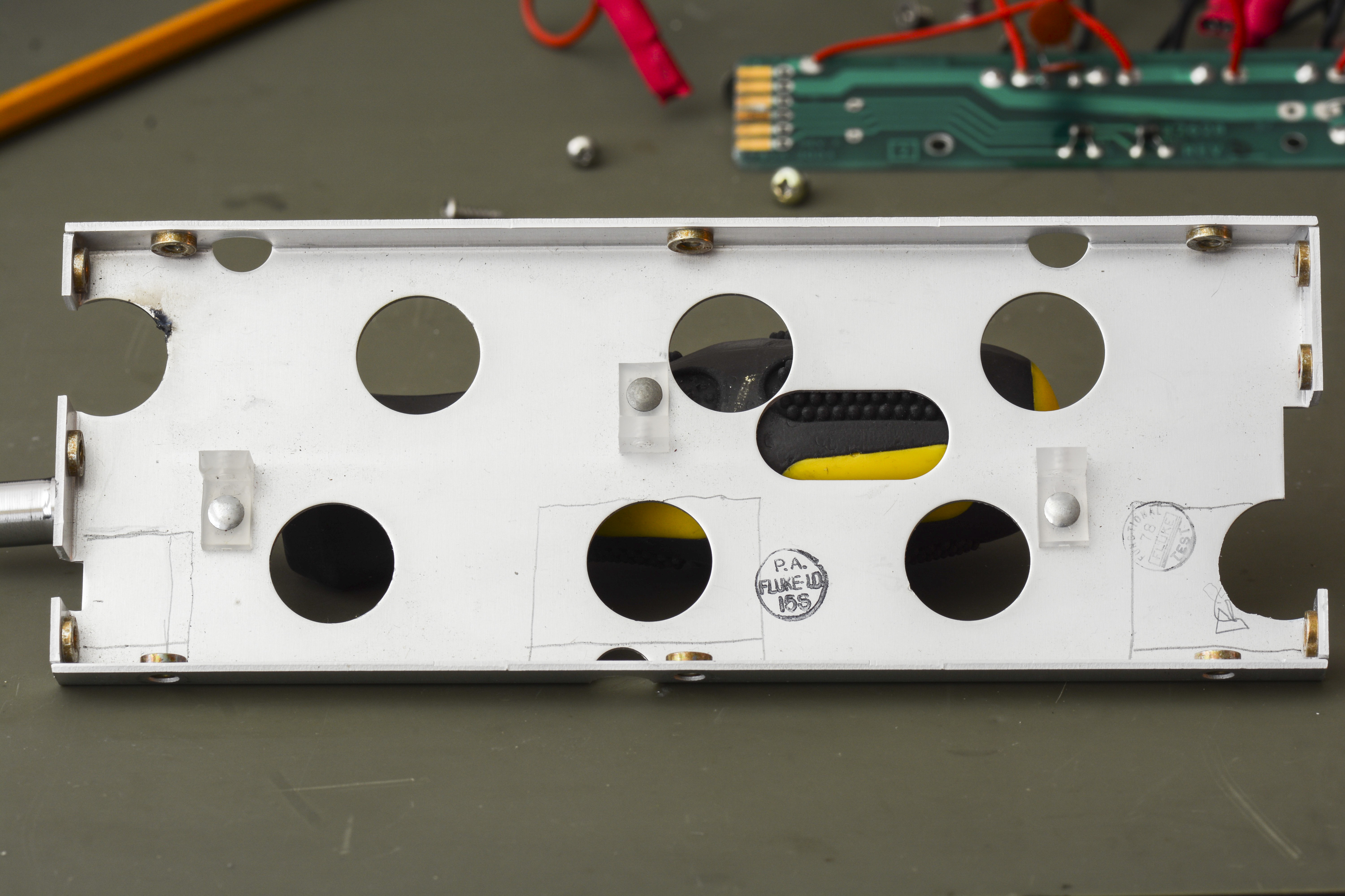
Chassis
No obvious problems found upon chassis condition check. Internal oven block was not disassembled or opened at this point.

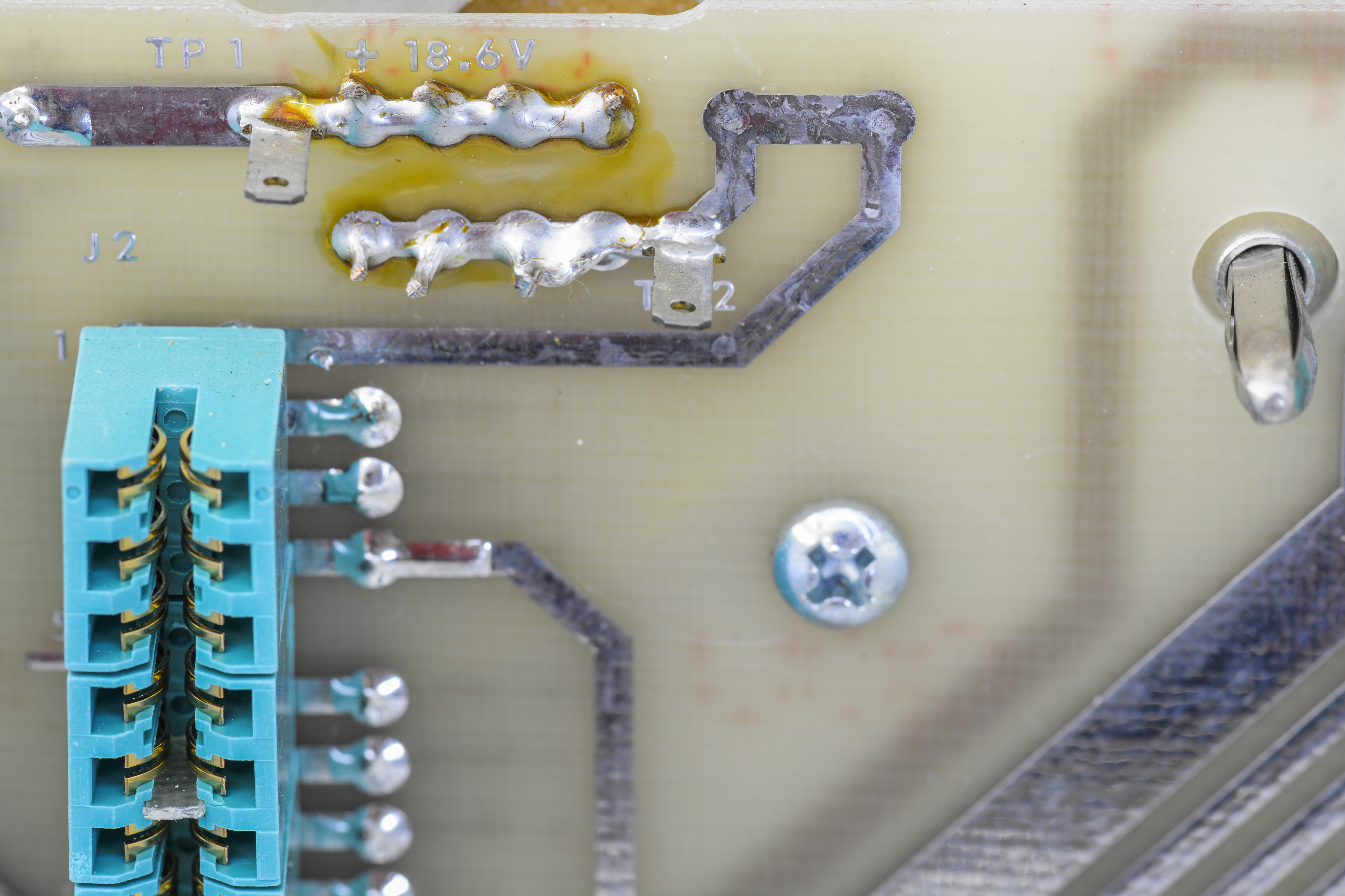
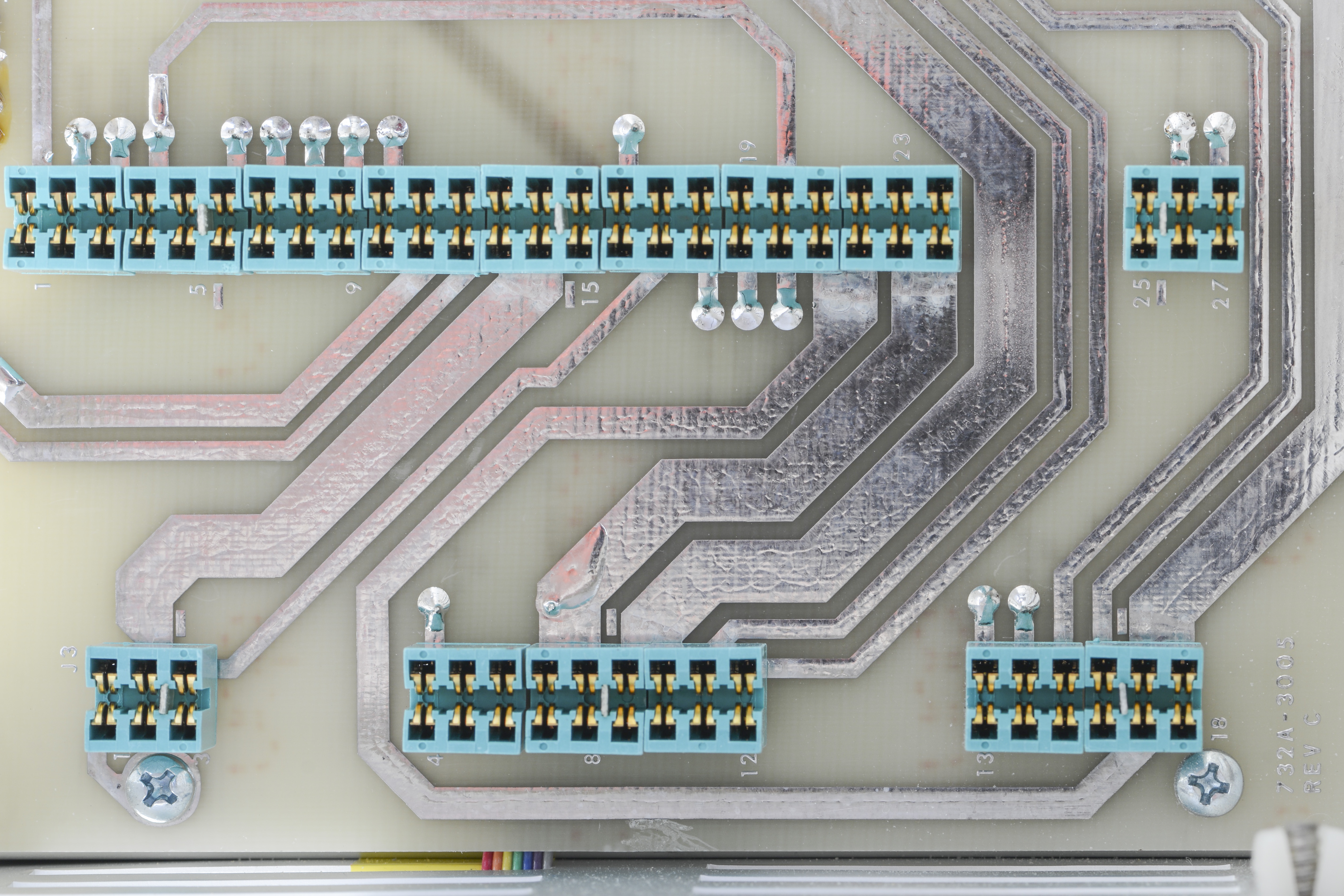
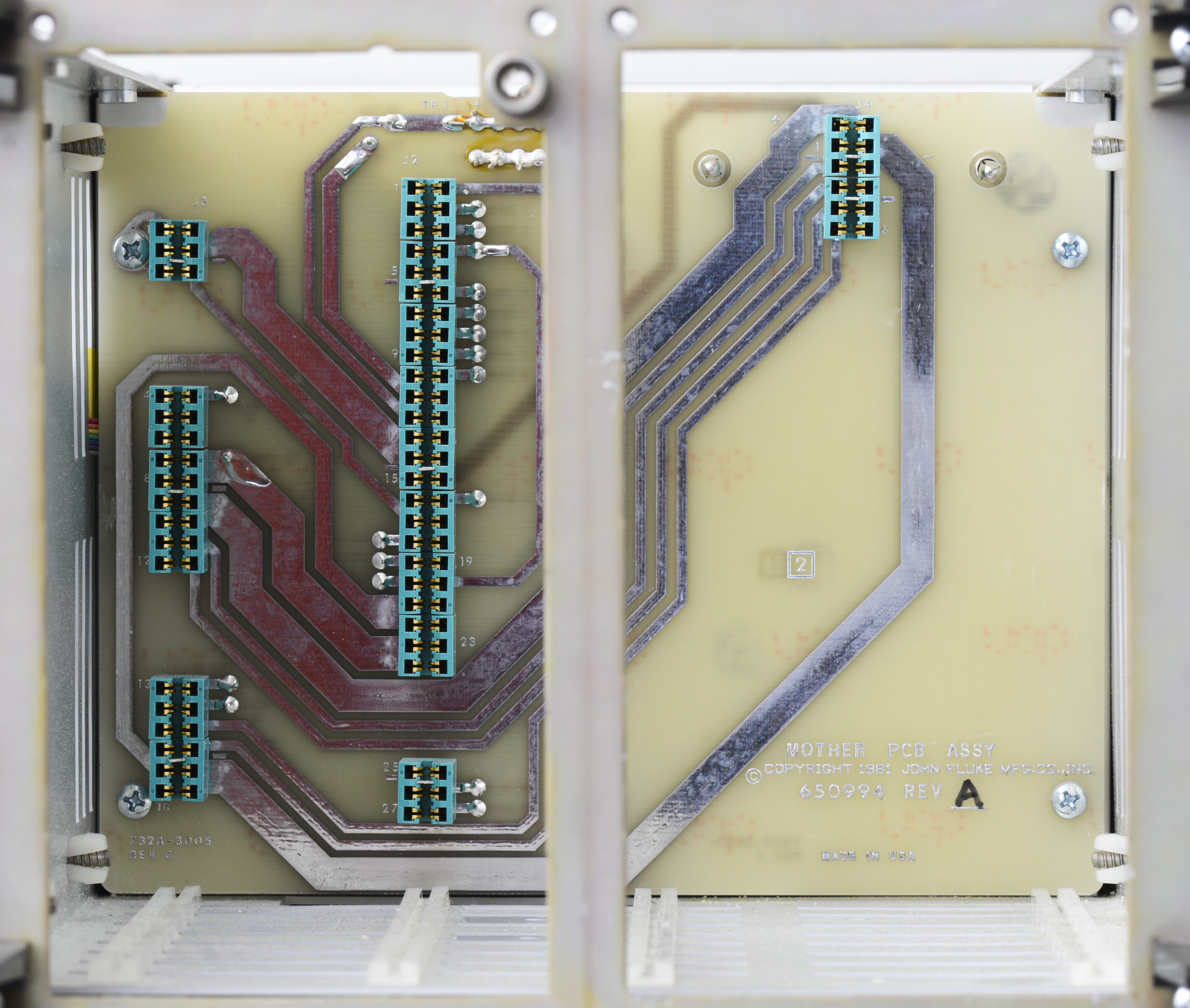
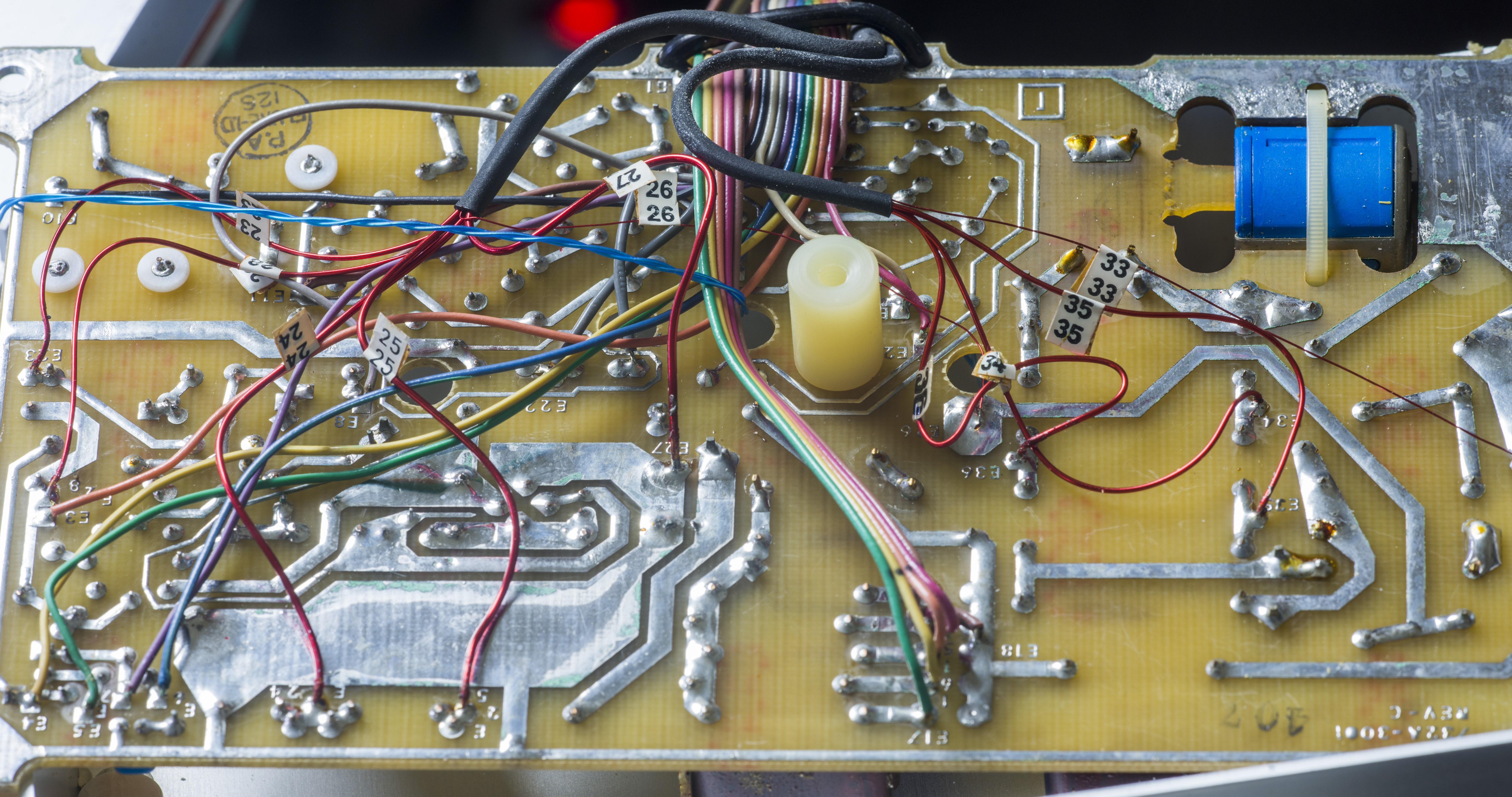
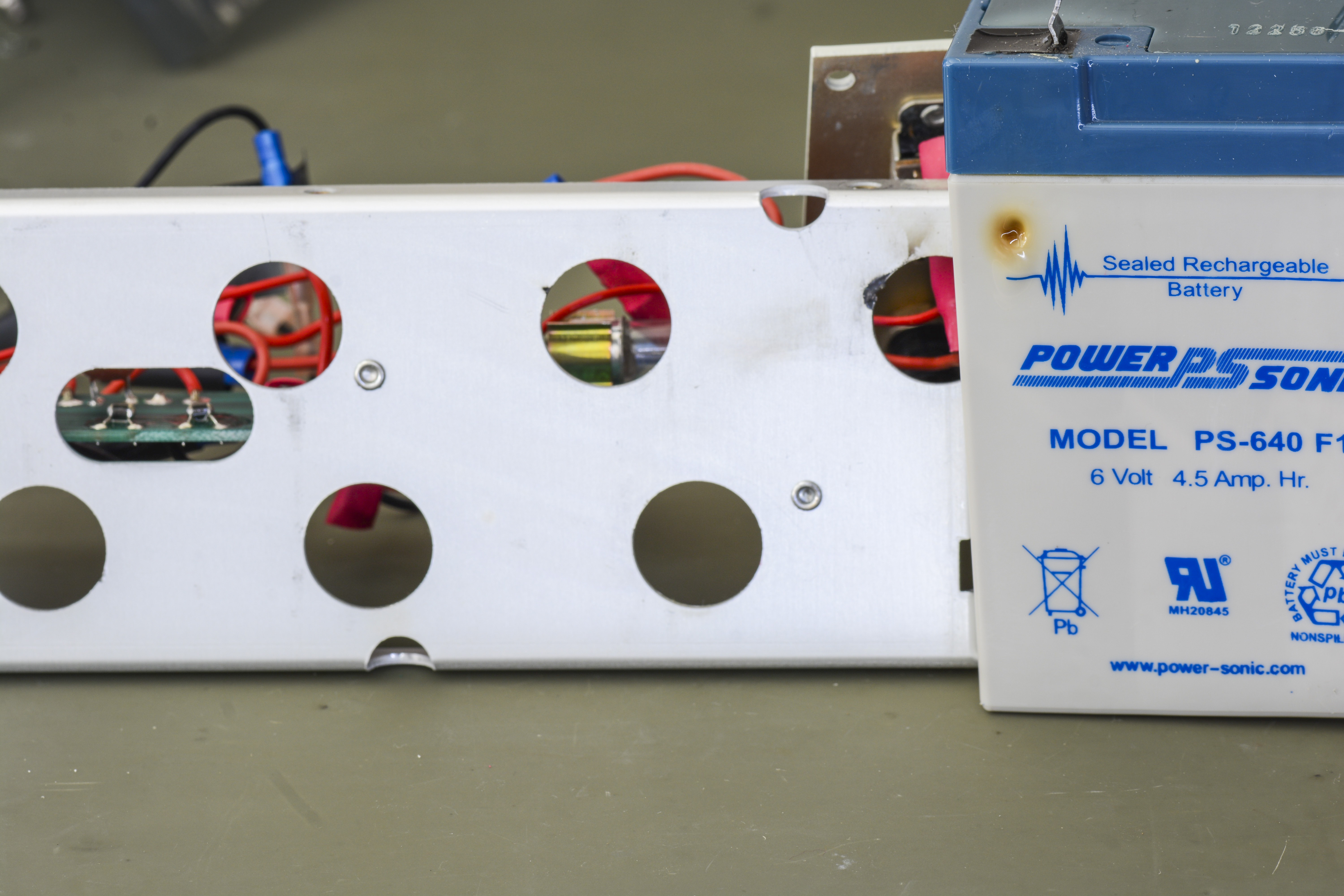
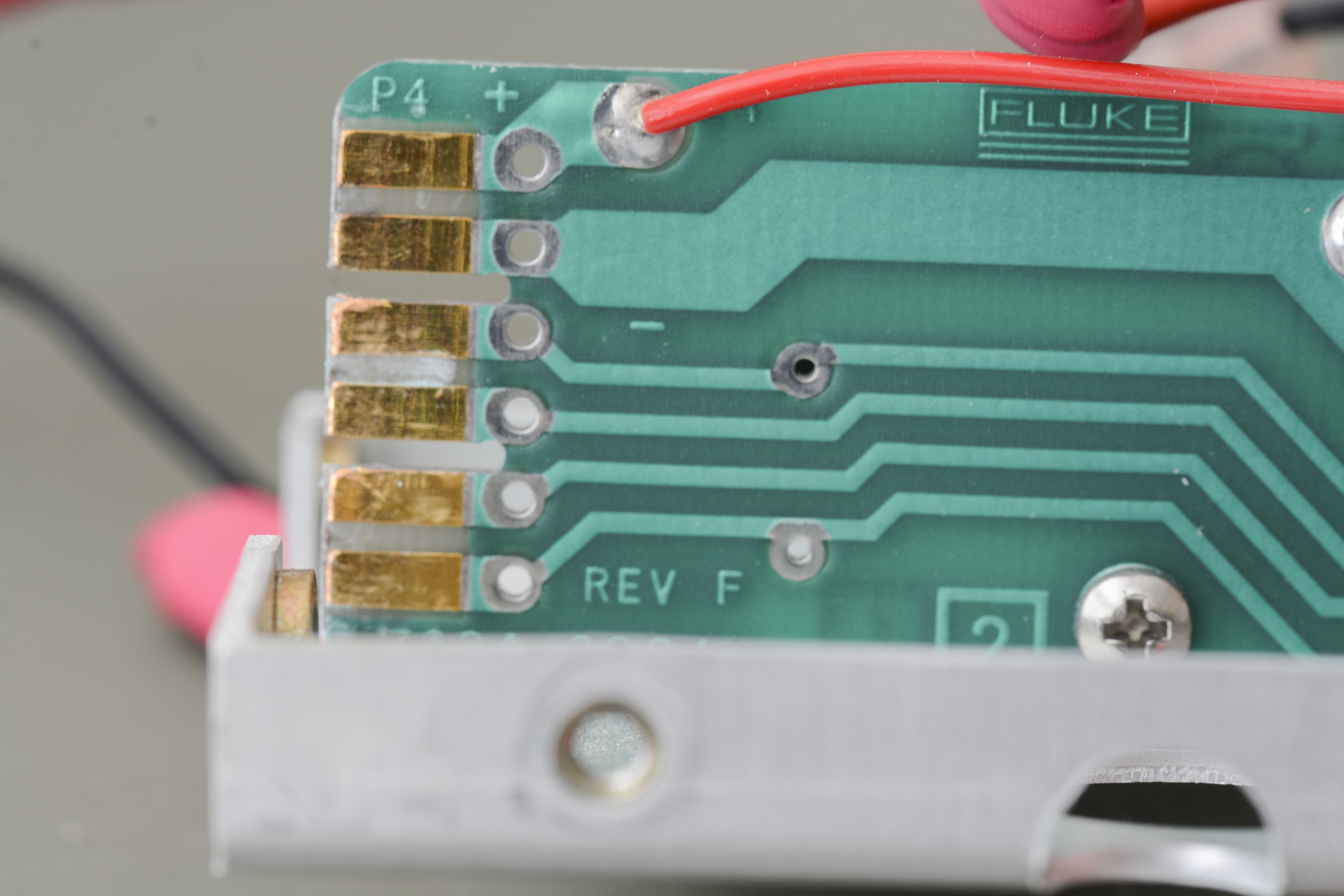
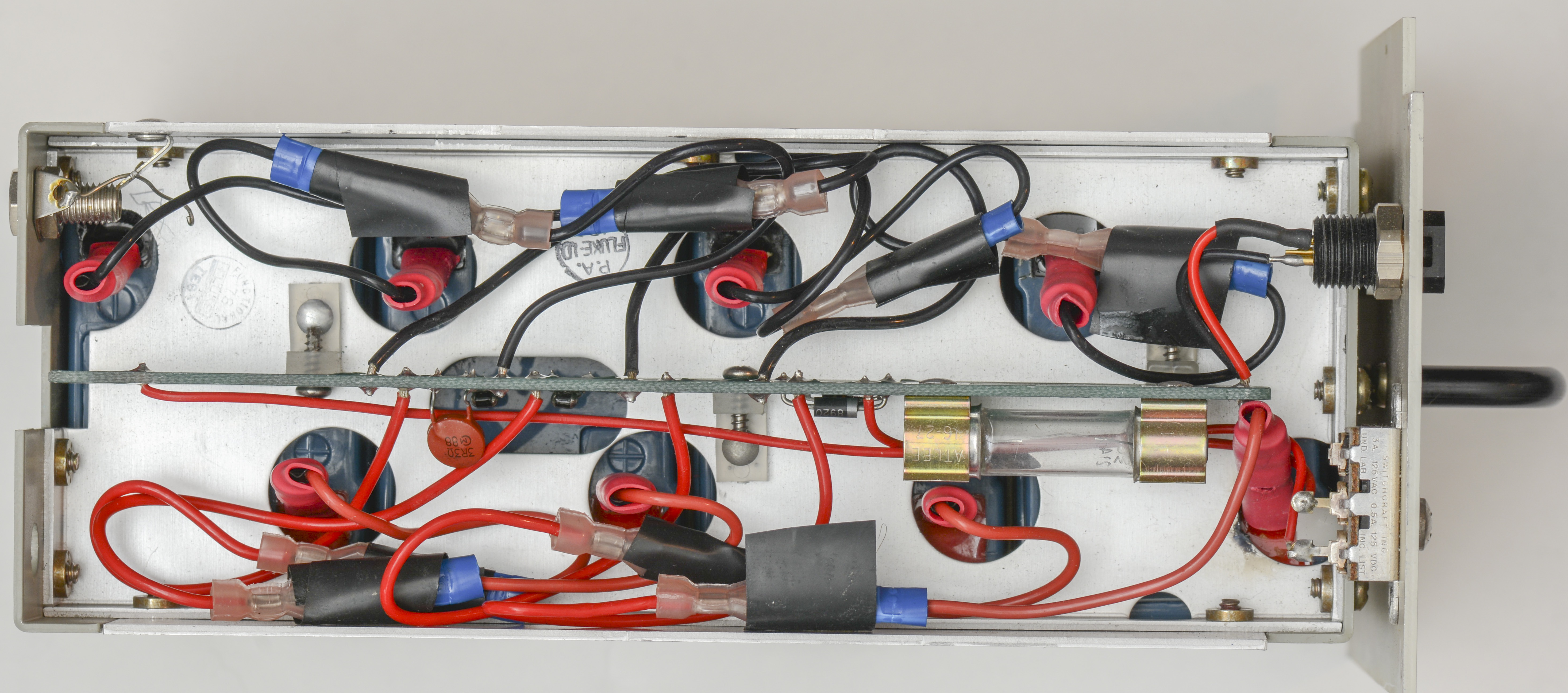
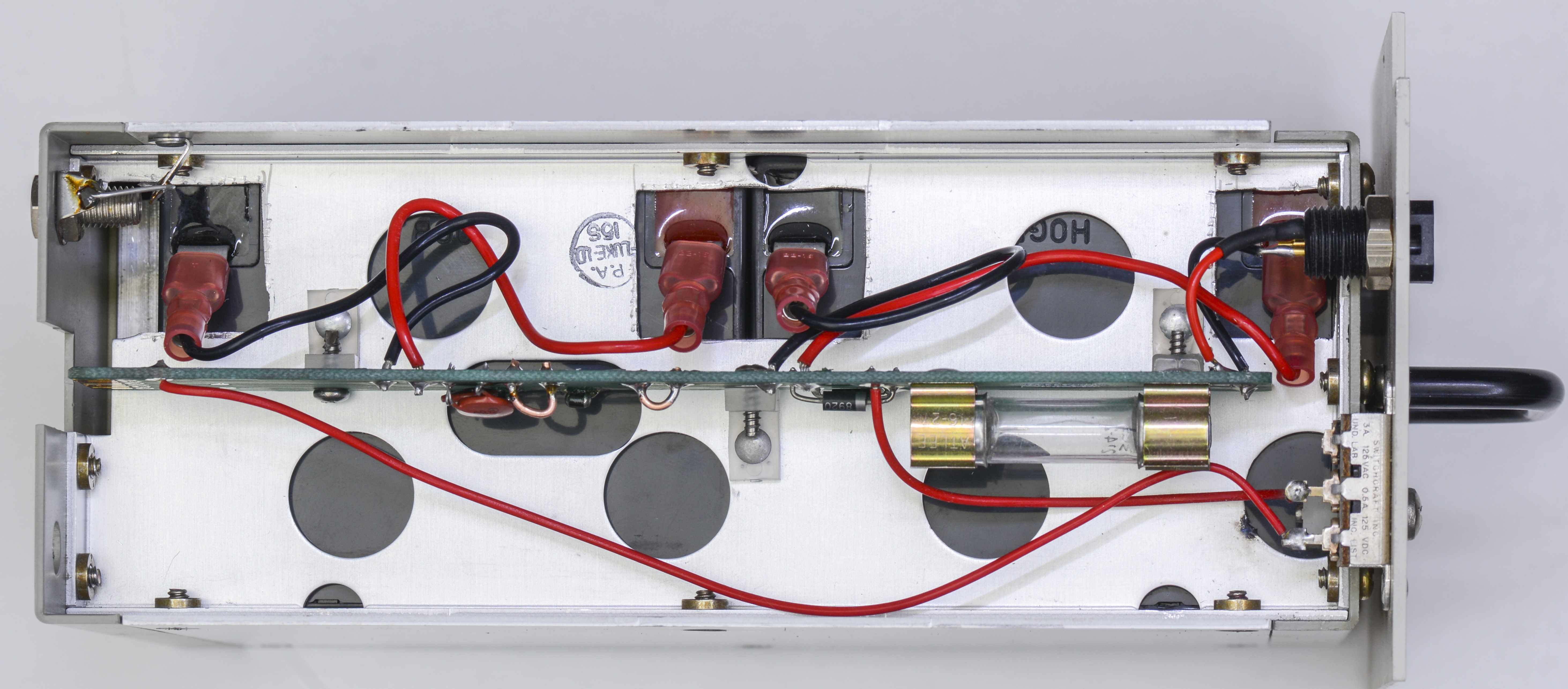
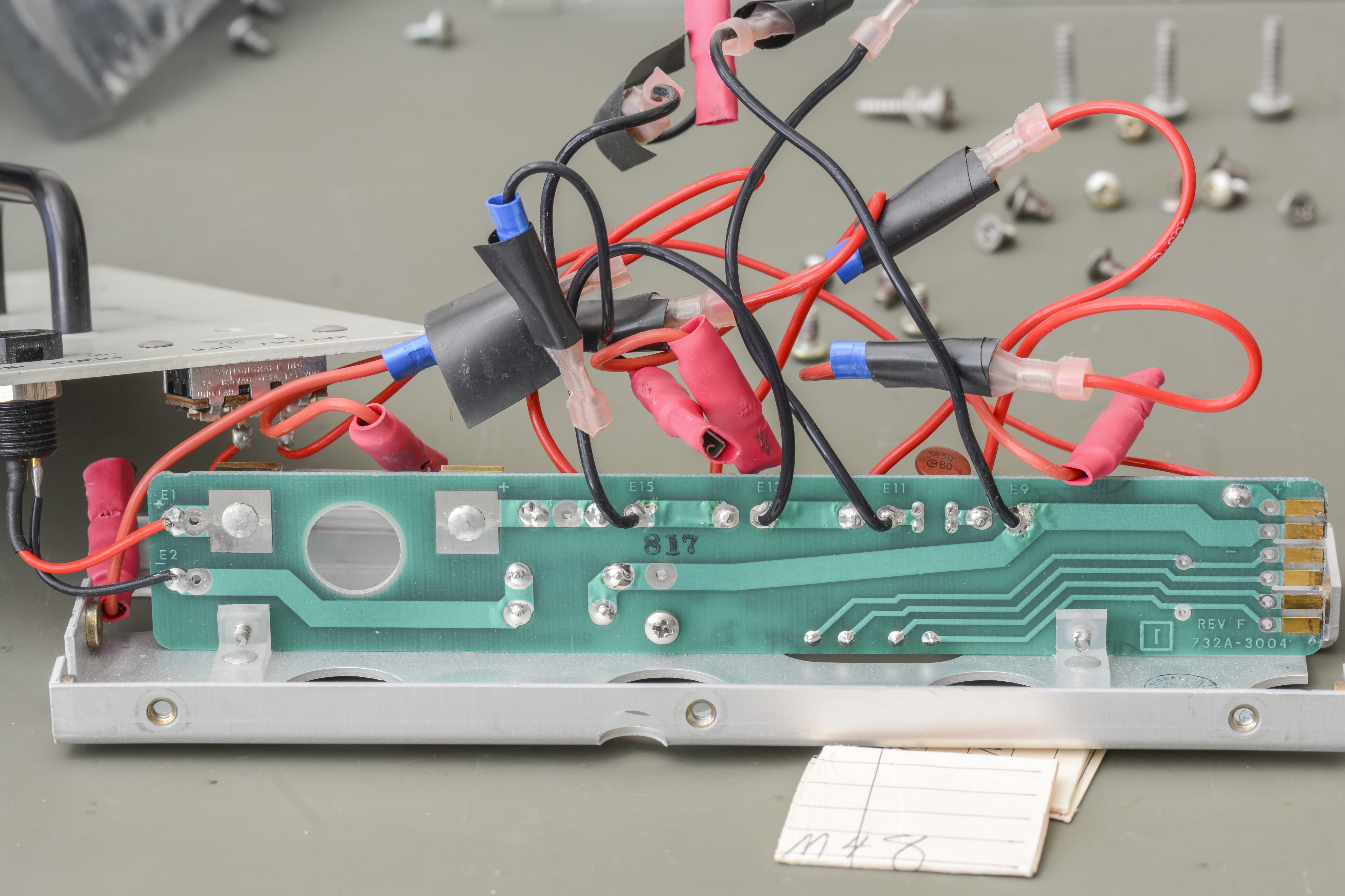
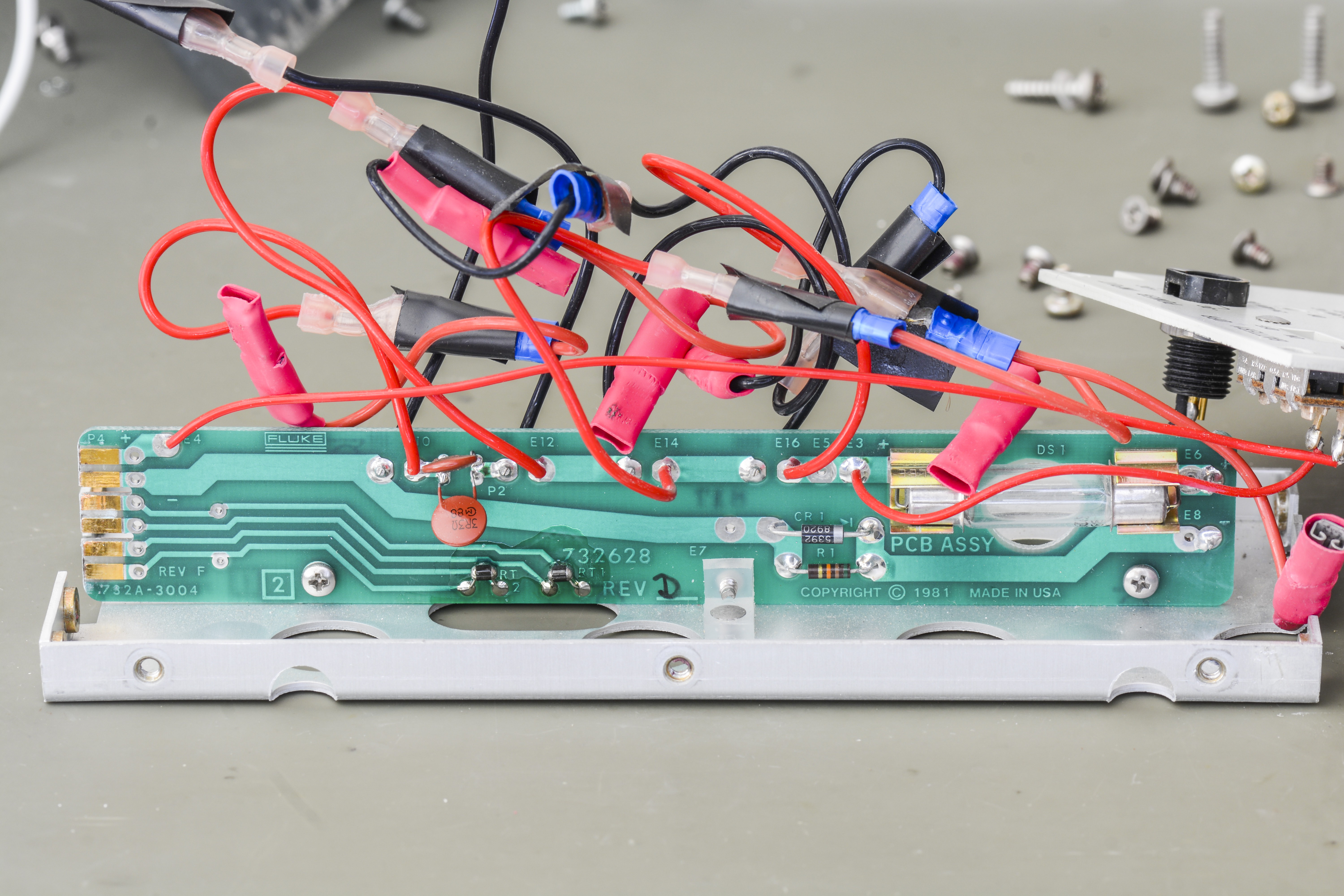
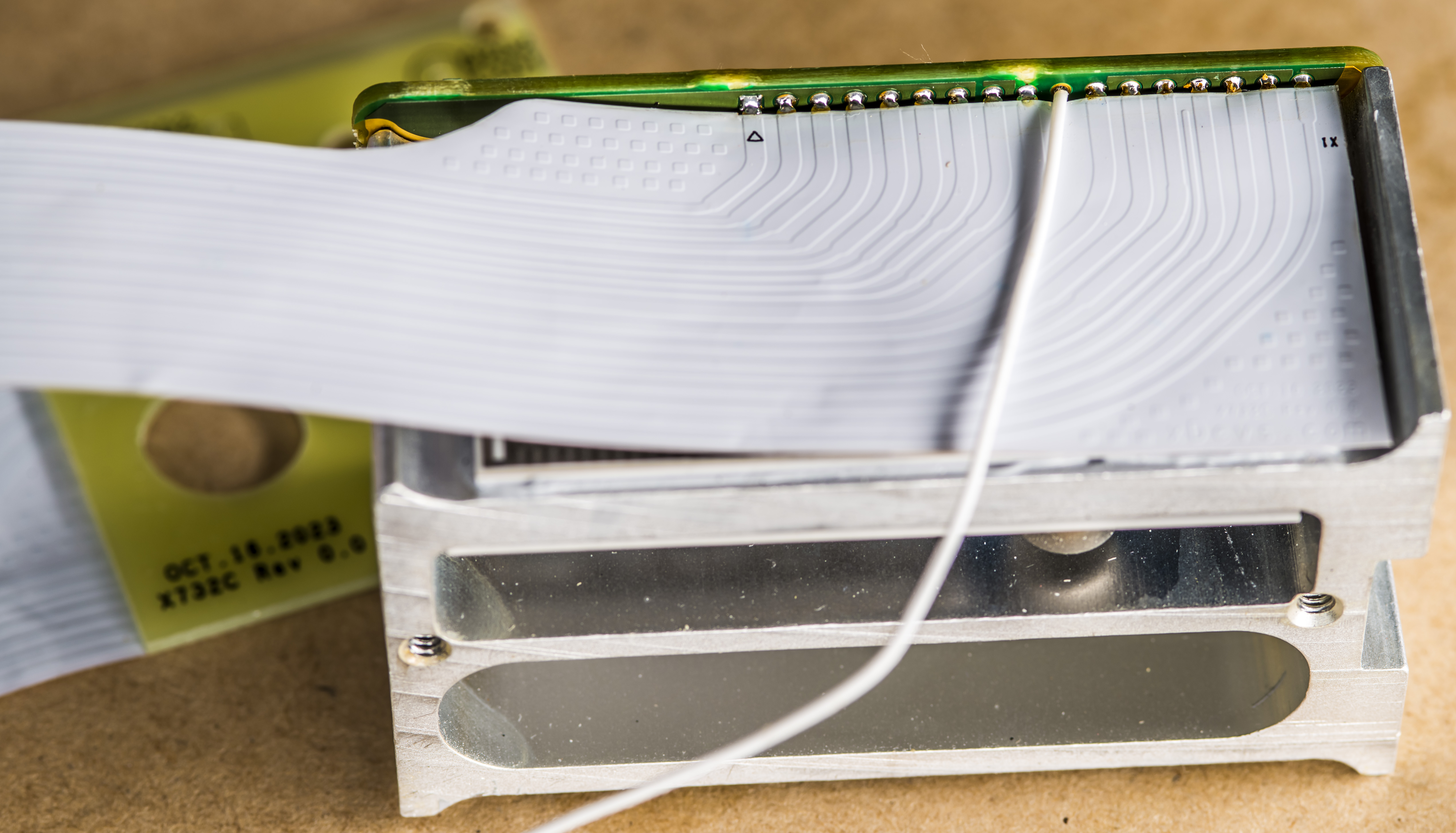
Image 21: Contact and connectors condition on the backplane board
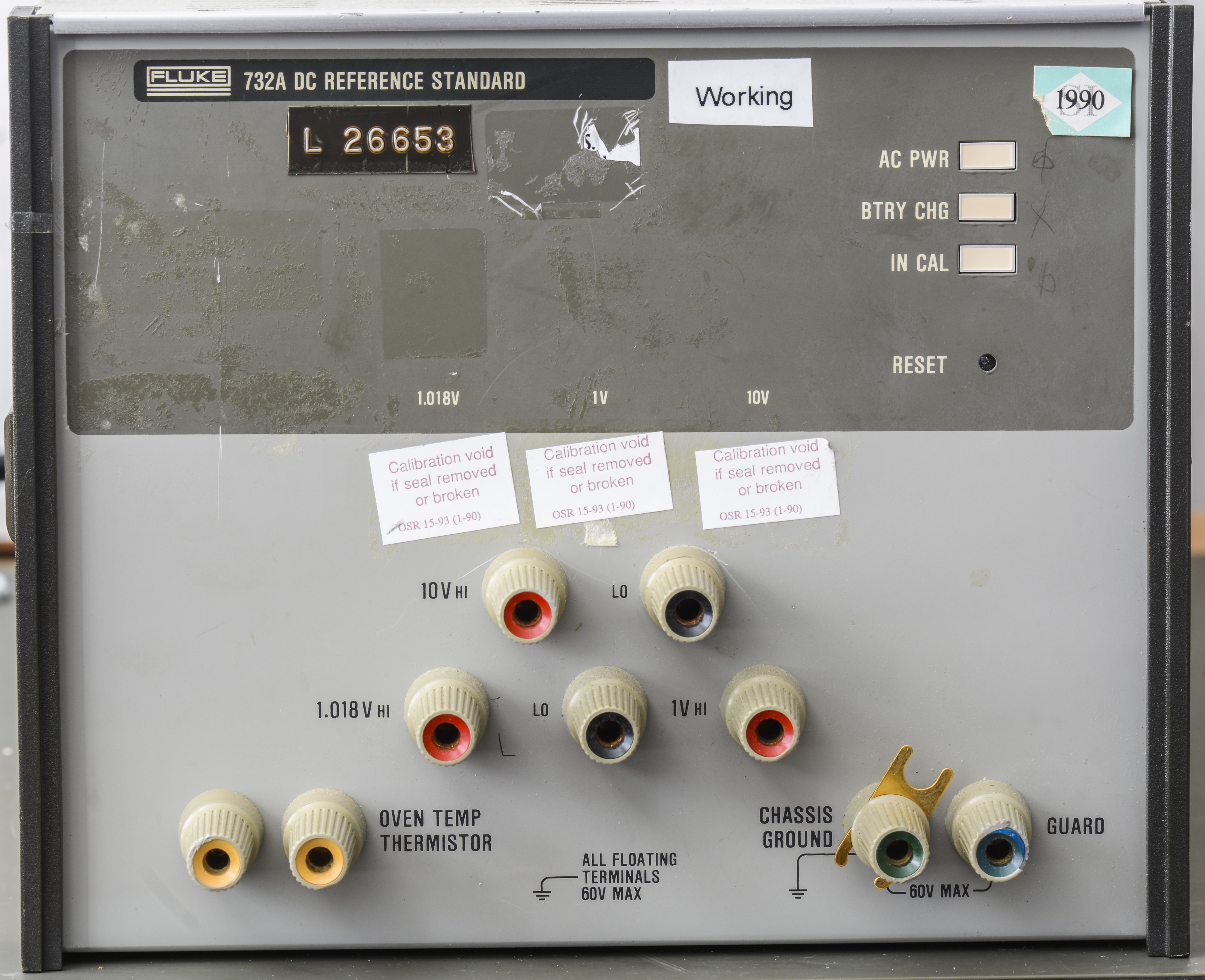
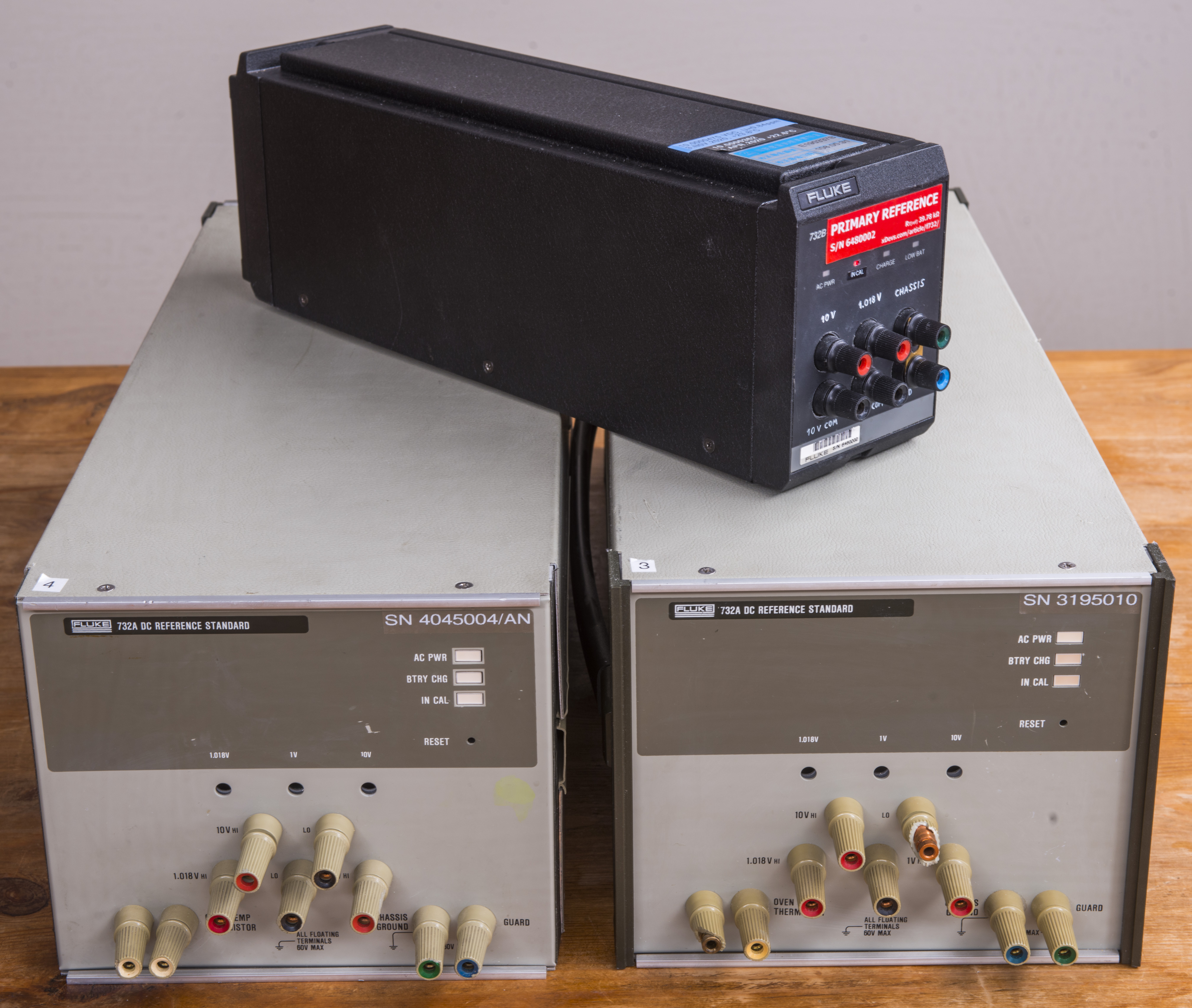
Serial number can be found on the back of the 732A as well.

Image 22: Serial number label for this Fluke 732A
Reassembly and first power on smoke test
Thermal camera is handy for first power-ups to visualize if anything heating excessively over +70 °C. This would be a better way to investigate possible problems before we get to the point of smelling magic smoke escaping the chips. Remember, once magic smoke is released, there is no way to put it back into the component to make it work again.
Battery charger adjustments and verification
It is important to check and adjust battery floating and charge peak voltages. We don’t want a charger circuit to overcharge chemical battery with high voltage as that will reduce the battery life significantly and may cause even more damage if left for extended period of time.
Without adjustment of the battery voltage to match specs of modern batteries used in old 732A charger likely would be overcharging the cells and cause loss of capacity or possible damages after just few months. Always consult the specifications for your batteries.
Initial 24-hour stability benchmark
For this test 732A was connected to the characterized and freshly calibrated HP 3458A 8½-digit DMM and measured during 24 hour period. Few additional 3458A and Keithley 2002 were used to monitor 1 V, 1.018 V and thermistor outputs at the same time so we get the overall health idea of this freshly repaired unit. AC source Chrome 61604 was configured to supply stable 120 VAC and 60 Hz.
Image 23: AC power measurement from source with 732A charging it’s batteries
With battery in trickle charge more 732A consuming about 25 W with power factor about 0.82. Battery voltage was measured by second K2002 with input connected to battery jack on the back of the 732A. Once battery fully charged power consumption from AC source dropped to about 15 W, which is reasonable for long-term operation as lab standard w/o needing a fan.
Image 24: Battery pack voltage measurement
First output was measured around +9.999964 VDC and looking like a good start after repair. DMM was calibrated a while ago in April 2023, so this is only relative measurement with degraded uncertainty.
Image 25: Output voltage initial voltage measurement
Let’s do number of tests next. 732A was powered up and warmed to proper operating temperatures to go with adjustments for battery voltage and charger levels. All the adjustments done according to Fluke 732A instruction manual for repair.
Thermal images of the A3 and A4 cards
Temperatures of all power components were checked with a fancy thermal imaging camera.
Image 26: Thermal image of the components on the circuit board A3
All temperatures were good with hottest for diode bridge on A3 at +65 °C.
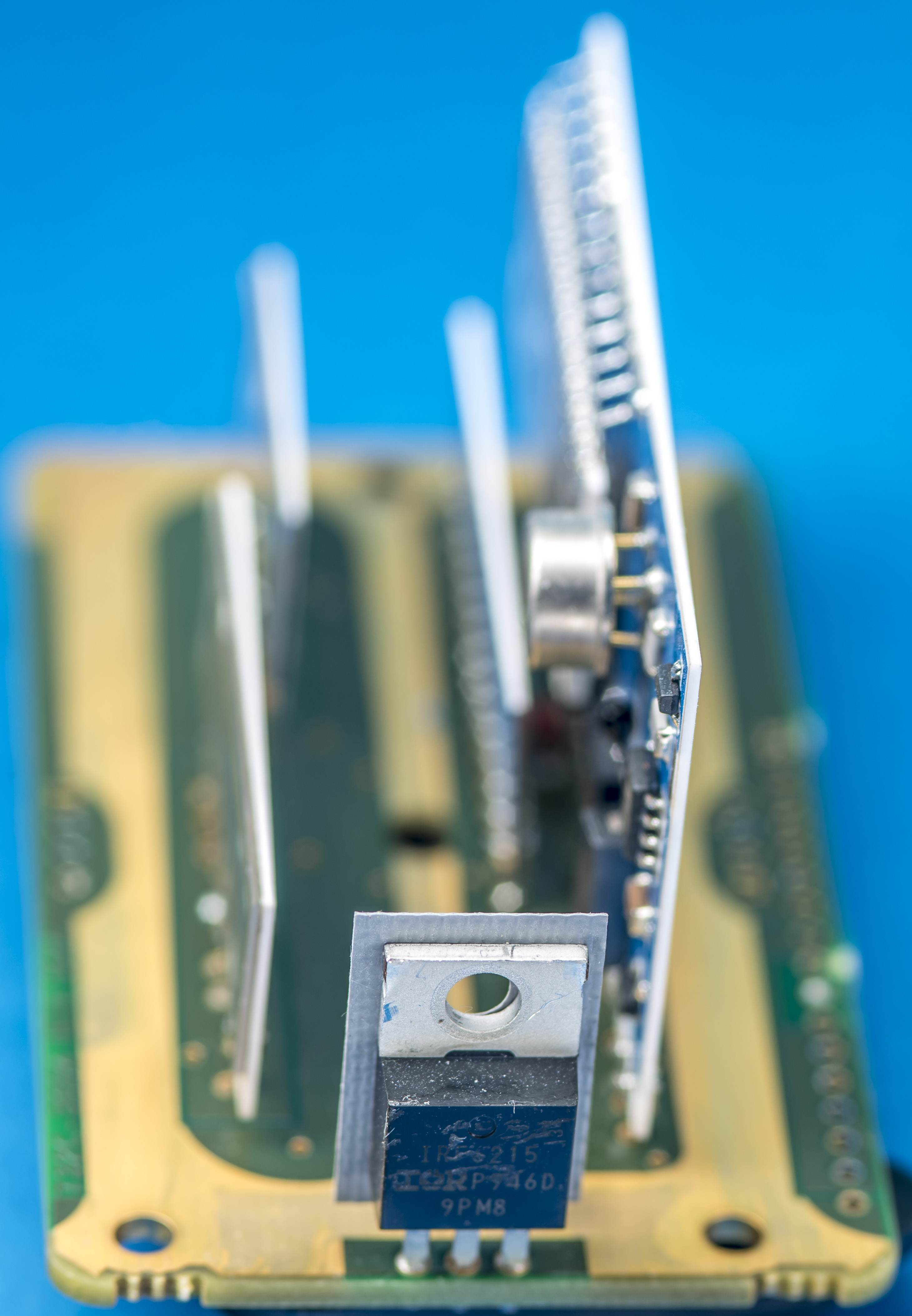
Image 27: Thermal image of the transistors from A4 board
Transistor on A4 was keeping warm at around +68 °C. Everything else was much cooler than these hottest parts.
Performance tests
Now that 732A is all back together and warmed up we can go ahead with performance verifications. DC voltage standard can be checked and verified for many aspects and performance parameters but I like to focus on three main points such as noise, battery/mains operation and output stability over longer durations.
10V output noise performance verification
Noise is another important performance parameter of a DC voltage standard. Ideally we’d want constant voltage level at the output but due to zener and active components we always end up with some small but measurable random noise at the output. For instrument like 732A typical amplitude is about 1 µV pk-pk in 0.1-10 Hz bandwidth for 10 V output. This can be tested with high gain LNA and oscilloscope. Some of such measurement process was already shown at xDevs before.
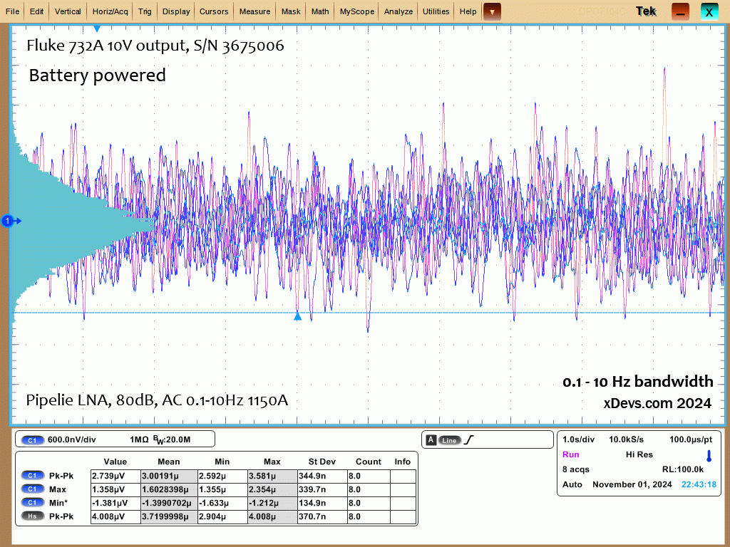
Image 28: Noise measurement in 0.1 – 10 Hz bandwidth for 10 V output, battery powered
Noise measured at the output was about 3 µV peak to peak, which is close to Fluke 732A specification limit, which is 1 µV RMS. I’d say this unit is within reasonable margins and no troubleshooting is required at this moment in time.
Battery life, AC/DC power difference test
732A specified for typical 12 hours of battery life at +23 °C lab conditions. This test is easy to do, just connect DVM such as Keithley 2002 to the output and leave the 732A running on battery power until the output goes out of the regulation. Another useful information gained from this test would be measurement of the possible output voltage change or shifts if 732A is mains AC powered or battery powered.
Usually that is a bigger problem for more compact standards, such as 732B or 7001 because heat generated inside of the instrument might slightly differ, enough to be visible in the output stability. Another possible reason of differences could be bad insulation to the earth or possible leakages, forming unwanted parasitic ground loops.
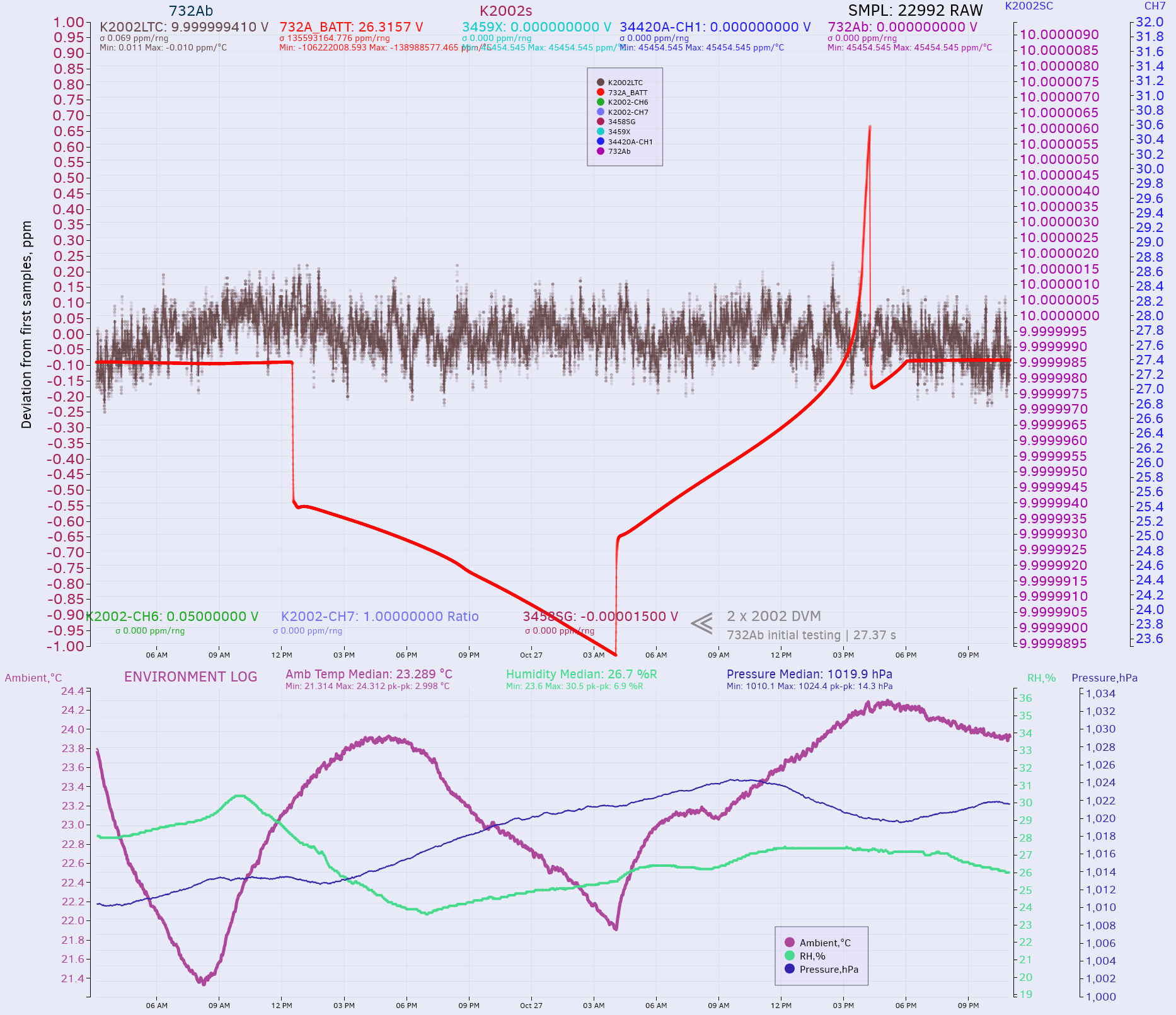
Image 29: Initial 10 V measurement with battery discharge and charge cycle
This data reveals so far that the charger was tweaked to correct voltage for stand-by operation about 27.34 V and standard was able to run 15 hours on single charge without any issues. I did not see any changes in 10 V output voltage between AC powered operation or floated battery mode either. This is a very good sign and instills confidence that no oven compartment disassembly or repairs are needed for this unit. Output voltage was pretty close to 10 V nominal value, so we don’t need to mess with trimmers either. This specific modified Keithley 2002 was calibrated on 26 April 2023.
DC Output calibration against lab standards
For final calibration 732A was connected to zener bank array of 15 other standards and measured in series opposition method with Keithley 2182A sensitive nanovoltmeter and DataProof 160A scanner. This is a best way to calibrate 10 V DC standards without expensive and elaborate involvement of the quantum voltage standard calibrations.
Greatly reduced sensitivity to gain, linearity and noise errors from the DMM are the key benefits of series opposition comparison approach. This is due to the use of most sensitive range to measure only small differential voltages between the calibrated source and unknown device under test. With capable scanner polarity of such measurement can be also reversed, furthre removing thermal emf errors at the interconnect points.
Calibration values presented in this article are not accredited certification nor legally traceable to the international metrology realization of voltage. They are unofficial best effort results valid only for educational purpose, with data valid only during this device time at xDevs lab.
Calibration data for this standard is provided in table here.
| Date and time | Voltage calibration | Ambient temperature | Humidity | Pressure | Deviation from first value |
|---|---|---|---|---|---|
| 10/28/2024 03:35:43 | 9.99999921 V ±0.2 µV/V | +22.89 °C | 32.0 % | 1021.6 hPa | Reference |
| 10/28/2024 04:32:54 | 9.99999956 V ±0.2 µV/V | +22.7 °C | 31.8 % | 1021.6 hPa | 0.035 µV/V |
| 10/28/2024 05:30:02 | 9.99999984 V ±0.2 µV/V | +22.57 °C | 31.6 % | 1021.9 hPa | 0.063 µV/V |
| 10/28/2024 06:27:10 | 9.99999931 V ±0.2 µV/V | +22.48 °C | 31.5 % | 1022.5 hPa | 0.010 µV/V |
| 10/28/2024 07:24:17 | 9.99999945 V ±0.2 µV/V | +22.35 °C | 31.5 % | 1023 hPa | 0.024 µV/V |
| 10/28/2024 08:21:24 | 9.99999937 V ±0.2 µV/V | +22.25 °C | 31.5 % | 1023.5 hPa | 0.016 µV/V |
| 10/28/2024 09:18:34 | 9.99999933 V ±0.2 µV/V | +22.2 °C | 31.5 % | 1024 hPa | 0.012 µV/V |
| 10/28/2024 10:15:43 | 9.99999884 V ±0.2 µV/V | +22.33 °C | 31.7 % | 1024.5 hPa | -0.037 µV/V |
| 10/28/2024 11:12:52 | 9.99999901 V ±0.2 µV/V | +22.49 °C | 31.9 % | 1024.6 hPa | -0.020 µV/V |
| 10/28/2024 12:09:59 | 9.99999880 V ±0.2 µV/V | +22.57 °C | 32.3 % | 1024.5 hPa | -0.041 µV/V |
| 10/28/2024 13:07:01 | 9.99999884 V ±0.2 µV/V | +22.66 °C | 32.6 % | 1024.2 hPa | -0.038 µV/V |
| 10/28/2024 14:04:01 | 9.99999953 V ±0.2 µV/V | +22.78 °C | 32.6 % | 1023.5 hPa | 0.032 µV/V |
| 10/28/2024 15:01:03 | 9.99999927 V ±0.2 µV/V | +22.94 °C | 32.9 % | 1023 hPa | 0.006 µV/V |
| 10/28/2024 15:58:10 | 10.0000002 V ±0.2 µV/V | +23.09 °C | 32.9 % | 1022.6 hPa | 0.096 µV/V |
| 10/28/2024 16:55:21 | 9.99999871 V ±0.2 µV/V | +23.2°C | 32.9 % | 1022.4 hPa | -0.050 µV/V |
| 10/28/2024 17:52:33 | 9.99999940 V ±0.2 µV/V | +22.94 °C | 33% | 1022.4 hPa | 0.019 µV/V |
| 10/28/2024 18:49:44 | 9.99999930 V ±0.2 µV/V | +22.71 °C | 32.7 % | 1022.8 hPa | 0.009 µV/V |
| 10/28/2024 19:46:51 | 9.99999902 V ±0.2 µV/V | +23.17 °C | 33.3 % | 1023.4 hPa | -0.019 µV/V |
| 10/28/2024 20:44:03 | 9.99999912 V ±0.2 µV/V | +23.24 °C | 33.7 % | 1023.9 hPa | -0.009 µV/V |
| 10/28/2024 21:41:16 | 10.0000005 V ±0.2 µV/V | +23.18 °C | 33.8 % | 1024.3 hPa | 0.126 µV/V |
| 10/28/2024 22:38:25 | 9.99999920 V ±0.2 µV/V | +23.16 °C | 33.8 % | 1024.6 hPa | -0.002 µV/V |
| 10/28/2024 23:35:36 | 9.99999916 V ±0.2 µV/V | +23.16 °C | 33.9 % | 1024.8 hPa | -0.005 µV/V |
| 10/29/2024 00:32:48 | 9.99999864 V ±0.2 µV/V | +23.17 °C | 33.9 % | 1024.9 hPa | -0.057 µV/V |
| 10/29/2024 01:29:58 | 9.99999868 V ±0.2 µV/V | +23.09 °C | 33.7 % | 1025 hPa | -0.053 µV/V |
| 10/29/2024 02:27:09 | 9.99999940 V ±0.2 µV/V | +22.97 °C | 33.5 % | 1024.9 hPa | 0.019 µV/V |
| 10/29/2024 03:24:19 | 9.99999911 V ±0.2 µV/V | +22.89 °C | 33.7 % | 1025 hPa | -0.010 µV/V |
| 10/29/2024 04:21:26 | 9.99999924 V ±0.2 µV/V | +22.79 °C | 33.6 % | 1024.7 hPa | 0.003 µV/V |
| 10/29/2024 05:18:35 | 9.99999927 V ±0.2 µV/V | +22.69 °C | 33.3 % | 1024.9 hPa | 0.006 µV/V |
| 10/29/2024 06:15:47 | 9.99999903 V ±0.2 µV/V | +22.56 °C | 33% | 1025 hPa | -0.018 µV/V |
| 10/29/2024 07:12:54 | 9.99999934 V ±0.2 µV/V | +22.45 °C | 32.9 % | 1025.1 hPa | 0.013 µV/V |
| 10/29/2024 08:10:01 | 9.99999836 V ±0.2 µV/V | +22.33 °C | 32.7 % | 1025 hPa | -0.085 µV/V |
| 10/29/2024 09:07:08 | 9.99999946 V ±0.2 µV/V | +22.35 °C | 32.7 % | 1025.3 hPa | 0.025 µV/V |
| 10/29/2024 10:04:16 | 9.99999871 V ±0.2 µV/V | +22.45 °C | 33.2 % | 1025.4 hPa | -0.050 µV/V |
| 10/29/2024 11:01:23 | 9.99999834 V ±0.2 µV/V | +22.58 °C | 33.6 % | 1025.4 hPa | -0.087 µV/V |
| 10/29/2024 11:58:31 | 9.99999837 V ±0.2 µV/V | +22.68 °C | 34% | 1025 hPa | -0.084 µV/V |
| 10/29/2024 12:55:37 | 9.99999850 V ±0.2 µV/V | +22.82 °C | 34.3 % | 1024.4 hPa | -0.071 µV/V |
| 10/29/2024 13:52:43 | 9.99999852 V ±0.2 µV/V | +22.98 °C | 34.7 % | 1023.4 hPa | -0.069 µV/V |
| 10/29/2024 14:49:53 | 9.99999932 V ±0.2 µV/V | +23.12 °C | 35% | 1022.5 hPa | 0.011 µV/V |
| 10/29/2024 15:47:02 | 9.99999932 V ±0.2 µV/V | +23.3°C | 35.4 % | 1022.1 hPa | 0.011 µV/V |
| 10/29/2024 16:44:16 | 9.99999985 V ±0.2 µV/V | +23.44 °C | 35.7 % | 1022 hPa | 0.075 µV/V |
| 10/29/2024 17:41:28 | 9.99999854 V ±0.2 µV/V | +23.57 °C | 36.1 % | 1021.8 hPa | -0.067 µV/V |
| 10/29/2024 18:38:40 | 9.99999866 V ±0.2 µV/V | +23.67 °C | 36.8 % | 1022 hPa | -0.056 µV/V |
| 10/29/2024 19:35:55 | 9.99999893 V ±0.2 µV/V | +23.79 °C | 37.2 % | 1022.2 hPa | -0.028 µV/V |
| 10/29/2024 20:33:10 | 9.99999916 V ±0.2 µV/V | +23.85 °C | 38.7 % | 1022 hPa | -0.005 µV/V |
| 10/29/2024 21:30:27 | 9.99999904 V ±0.2 µV/V | +23.95 °C | 39.7 % | 1021.9 hPa | -0.017 µV/V |
| 10/29/2024 22:27:42 | 9.99999906 V ±0.2 µV/V | +24.02 °C | 39.8 % | 1021.9 hPa | -0.016 µV/V |
| 10/29/2024 23:25:00 | 9.99999849 V ±0.2 µV/V | +24.04 °C | 40.3 % | 1021.8 hPa | -0.072 µV/V |
| 10/30/2024 00:22:16 | 9.99999929 V ±0.2 µV/V | +24.1 °C | 40.4 % | 1021.6 hPa | 0.008 µV/V |
| 10/30/2024 01:19:36 | 9.99999902 V ±0.2 µV/V | +24.21 °C | 40.7 % | 1021.6 hPa | -0.019 µV/V |
| 10/30/2024 02:16:57 | 9.99999883 V ±0.2 µV/V | +24.26 °C | 40.8 % | 1021.6 hPa | -0.038 µV/V |
| 10/30/2024 03:14:16 | 9.99999892 V ±0.2 µV/V | +24.29 °C | 40.8 % | 1021.3 hPa | -0.029 µV/V |
| 10/30/2024 04:11:35 | 9.99999896 V ±0.2 µV/V | +24.31 °C | 40.7 % | 1021.1 hPa | -0.026 µV/V |
| 10/30/2024 05:08:52 | 9.99999908 V ±0.2 µV/V | +24.29 °C | 40.8 % | 1021.1 hPa | -0.013 µV/V |
| 10/30/2024 06:06:17 | 9.99999883 V ±0.2 µV/V | +24.2 °C | 41.1 % | 1021.1 hPa | -0.038 µV/V |
| 10/30/2024 07:03:39 | 9.99999898 V ±0.2 µV/V | +24.08 °C | 41.5 % | 1021.2 hPa | -0.023 µV/V |
| 10/30/2024 08:01:03 | 9.99999838 V ±0.2 µV/V | +24.02 °C | 41.6 % | 1021.1 hPa | -0.084 µV/V |
| 10/30/2024 08:58:30 | 9.99999869 V ±0.2 µV/V | +23.96 °C | 41.8 % | 1021 hPa | -0.052 µV/V |
| 10/30/2024 09:55:53 | 9.99999845 V ±0.2 µV/V | +24.01 °C | 42 % | 1021 hPa | -0.076 µV/V |
| 10/30/2024 10:53:15 | 9.99999909 V ±0.2 µV/V | +24.21 °C | 41.8 % | 1020.8 hPa | -0.012 µV/V |
| 10/30/2024 11:50:40 | 9.99999870 V ±0.2 µV/V | +24.35 °C | 42.1 % | 1020.2 hPa | -0.052 µV/V |
| 10/30/2024 12:48:00 | 9.99999827 V ±0.2 µV/V | +24.55 °C | 42.2 % | 1019.3 hPa | -0.094 µV/V |
| 10/30/2024 13:45:24 | 9.99999798 V ±0.2 µV/V | +24.7 °C | 42 % | 1018.2 hPa | -0.124 µV/V |
| 10/30/2024 14:42:50 | 9.99999830 V ±0.2 µV/V | +24.88 °C | 41.8 % | 1017.3 hPa | -0.092 µV/V |
| 10/30/2024 15:40:19 | 9.99999812 V ±0.2 µV/V | +25.07 °C | 41.8 % | 1016.8 hPa | -0.109 µV/V |
| 10/30/2024 16:37:55 | 9.99999835 V ±0.2 µV/V | +25.26 °C | 42 % | 1016.6 hPa | -0.087 µV/V |
| 10/30/2024 17:35:25 | 9.99999874 V ±0.2 µV/V | +25.44 °C | 42.2 % | 1016.3 hPa | -0.047 µV/V |
| 10/30/2024 18:32:57 | 9.99999888 V ±0.2 µV/V | +25.56 °C | 42.4 % | 1016.2 hPa | -0.033 µV/V |
| 10/30/2024 19:30:26 | 9.99999919 V ±0.2 µV/V | +25.5 °C | 42.9 % | 1016.4 hPa | -0.002 µV/V |
| 10/30/2024 20:28:01 | 9.99999890 V ±0.2 µV/V | +25.38 °C | 43.7 % | 1016.2 hPa | -0.032 µV/V |
| 10/30/2024 21:25:38 | 9.99999935 V ±0.2 µV/V | +25.13 °C | 44.3 % | 1016.1 hPa | 0.014 µV/V |
| 10/30/2024 22:23:08 | 9.99999888 V ±0.2 µV/V | +25.27 °C | 43.5 % | 1016.1 hPa | -0.033 µV/V |
| 10/30/2024 23:20:46 | 9.99999891 V ±0.2 µV/V | +25.21 °C | 43.3 % | 1016.1 hPa | -0.030 µV/V |
| 10/31/2024 00:18:25 | 9.99999951 V ±0.2 µV/V | +25.06 °C | 42.9 % | 1015.8 hPa | 0.029 µV/V |
| 10/31/2024 01:15:58 | 9.99999903 V ±0.2 µV/V | +24.97 °C | 42.4 % | 1015.5 hPa | -0.019 µV/V |
| 10/31/2024 02:13:19 | 9.99999918 V ±0.2 µV/V | +25.04 °C | 41 % | 1015 hPa | -0.004 µV/V |
| 10/31/2024 03:10:34 | 9.99999949 V ±0.2 µV/V | +24.91 °C | 40 % | 1014.8 hPa | 0.027 µV/V |
| 10/31/2024 04:07:44 | 9.99999861 V ±0.2 µV/V | +24.74 °C | 39.6 % | 1014.5 hPa | -0.061 µV/V |
| 10/31/2024 05:04:56 | 9.99999904 V ±0.2 µV/V | +24.55 °C | 39 % | 1014.6 hPa | -0.017 µV/V |
| 10/31/2024 06:02:04 | 9.99999912 V ±0.2 µV/V | +24.36 °C | 38.6 % | 1014.7 hPa | -0.009 µV/V |
| 10/31/2024 06:59:16 | 9.99999872 V ±0.2 µV/V | +24.15 °C | 38.2 % | 1014.6 hPa | -0.049 µV/V |
| 10/31/2024 07:56:24 | 9.99999890 V ±0.2 µV/V | +23.98 °C | 37.9 % | 1014.5 hPa | -0.032 µV/V |
| 10/31/2024 08:53:31 | 9.99999899 V ±0.2 µV/V | +23.87 °C | 38.1 % | 1014.8 hPa | -0.023 µV/V |
| 10/31/2024 09:50:45 | 9.99999911 V ±0.2 µV/V | +23.9 °C | 40 % | 1014.8 hPa | -0.010 µV/V |
| 10/31/2024 10:48:08 | 9.99999873 V ±0.2 µV/V | +23.99 °C | 41.7 % | 1014.5 hPa | -0.049 µV/V |
| 10/31/2024 11:45:26 | 9.99999919 V ±0.2 µV/V | +24.39 °C | 41.7 % | 1013.9 hPa | -0.002 µV/V |
| 10/31/2024 12:42:51 | 9.99999887 V ±0.2 µV/V | +24.76 °C | 41.7 % | 1013.3 hPa | -0.034 µV/V |
| 10/31/2024 13:40:17 | 9.99999914 V ±0.2 µV/V | +25.03 °C | 42.1 % | 1012.3 hPa | -0.007 µV/V |
| 10/31/2024 14:37:49 | 9.99999874 V ±0.2 µV/V | +25.26 °C | 42.7 % | 1011.3 hPa | -0.047 µV/V |
| 10/31/2024 15:35:30 | 9.99999884 V ±0.2 µV/V | +25.46 °C | 42.9 % | 1010.5 hPa | -0.037 µV/V |
| 10/31/2024 16:33:12 | 9.99999857 V ±0.2 µV/V | +25.64 °C | 43.2 % | 1010 hPa | -0.063 µV/V |
| 10/31/2024 17:30:54 | 9.99999815 V ±0.2 µV/V | +25.79 °C | 43.4 % | 1009.7 hPa | -0.106 µV/V |
| 10/31/2024 18:28:35 | 9.99999833 V ±0.2 µV/V | +25.95 °C | 44 % | 1009.6 hPa | -0.087 µV/V |
| 10/31/2024 19:26:21 | 9.99999820 V ±0.2 µV/V | +25.97 °C | 44.1 % | 1009.7 hPa | -0.101 µV/V |
| 10/31/2024 20:24:03 | 9.99999805 V ±0.2 µV/V | +25.92 °C | 44.5 % | 1009.5 hPa | -0.115 µV/V |
| 10/31/2024 21:21:45 | 9.99999807 V ±0.2 µV/V | +26 °C | 44.8 % | 1009.3 hPa | -0.114 µV/V |
| 10/31/2024 22:19:19 | 9.99999828 V ±0.2 µV/V | +26.14 °C | 44.9 % | 1009 hPa | -0.093 µV/V |
| 10/31/2024 23:16:59 | 9.99999810 V ±0.2 µV/V | +26.3 °C | 45.2 % | 1008.8 hPa | -0.111 µV/V |
| 11/01/2024 00:14:54 | 9.99999802 V ±0.2 µV/V | +26.45 °C | 45.5 % | 1008.2 hPa | -0.118 µV/V |
| 11/01/2024 01:12:50 | 9.99999791 V ±0.2 µV/V | +26.48 °C | 45.6 % | 1007.5 hPa | -0.130 µV/V |
| 11/01/2024 02:10:44 | 9.99999887 V ±0.2 µV/V | +26.4 °C | 45.4 % | 1007.2 hPa | -0.034 µV/V |
| 11/01/2024 03:08:29 | 9.99999836 V ±0.2 µV/V | +26.36 °C | 45.4 % | 1007 hPa | -0.085 µV/V |
| 11/01/2024 04:06:03 | 9.99999831 V ±0.2 µV/V | +26.29 °C | 45.4 % | 1006.5 hPa | -0.089 µV/V |
| 11/01/2024 05:03:11 | 9.99999813 V ±0.2 µV/V | +26.1 °C | 45.5 % | 1006.2 hPa | -0.107 µV/V |
| 11/01/2024 06:00:21 | 9.99999824 V ±0.2 µV/V | +25.99 °C | 45.8 % | 1006.3 hPa | -0.097 µV/V |
| 11/01/2024 06:57:49 | 9.99999825 V ±0.2 µV/V | +25.9 °C | 46 % | 1006.4 hPa | -0.096 µV/V |
| 11/01/2024 07:55:33 | 9.99999869 V ±0.2 µV/V | +25.87 °C | 46.3 % | 1006.8 hPa | -0.052 µV/V |
| 11/01/2024 08:53:22 | 9.99999851 V ±0.2 µV/V | +25.9 °C | 46.5 % | 1007.4 hPa | -0.070 µV/V |
| 11/01/2024 09:51:17 | 9.99999840 V ±0.2 µV/V | +25.95 °C | 46.4 % | 1007.6 hPa | -0.081 µV/V |
| 11/01/2024 10:49:03 | 9.99999841 V ±0.2 µV/V | +26.01 °C | 46.2 % | 1007.8 hPa | -0.080 µV/V |
| 11/01/2024 11:46:51 | 9.99999851 V ±0.2 µV/V | +26.19 °C | 46.3 % | 1007.5 hPa | -0.070 µV/V |
| 11/01/2024 12:44:43 | 9.99999862 V ±0.2 µV/V | +26.37 °C | 45.4 % | 1007.2 hPa | -0.059 µV/V |
| 11/01/2024 13:42:35 | 9.99999794 V ±0.2 µV/V | +26.53 °C | 43.2 % | 1006.6 hPa | -0.127 µV/V |
| 11/01/2024 14:40:25 | 9.99999870 V ±0.2 µV/V | +26.63 °C | 40.4 % | 1006.4 hPa | -0.050 µV/V |
| 11/01/2024 15:38:18 | 9.99999862 V ±0.2 µV/V | +26.66 °C | 37.5 % | 1006.5 hPa | -0.059 µV/V |
| 11/01/2024 16:36:06 | 9.99999893 V ±0.2 µV/V | +26.65 °C | 37.2 % | 1006.8 hPa | -0.027 µV/V |
| 11/01/2024 17:33:58 | 9.99999848 V ±0.2 µV/V | +26.61 °C | 35.8 % | 1007.4 hPa | -0.073 µV/V |
| 11/01/2024 18:31:46 | 9.99999882 V ±0.2 µV/V | +26.15 °C | 30.2 % | 1008.4 hPa | -0.039 µV/V |
| 11/01/2024 19:29:28 | 9.99999891 V ±0.2 µV/V | +25.85 °C | 28 % | 1009.6 hPa | -0.030 µV/V |
| 11/01/2024 20:27:08 | 9.99999912 V ±0.2 µV/V | +25.32 °C | 30.8 % | 1011 hPa | -0.009 µV/V |
| 11/01/2024 21:24:35 | 9.99999866 V ±0.2 µV/V | +24.4 °C | 31 % | 1012.1 hPa | -0.055 µV/V |
| 11/01/2024 22:22:00 | 9.99999908 V ±0.2 µV/V | +24.22 °C | 31.1 % | 1013 hPa | -0.013 µV/V |
| 11/01/2024 23:19:32 | 9.99999861 V ±0.2 µV/V | +25 °C | 32.7 % | 1013.7 hPa | -0.060 µV/V |
| 11/02/2024 00:17:02 | 9.99999908 V ±0.2 µV/V | +25.11 °C | 32 % | 1014.3 hPa | -0.013 µV/V |
| 11/02/2024 01:14:27 | 9.99999878 V ±0.2 µV/V | +25.11 °C | 31.8 % | 1014.8 hPa | -0.042 µV/V |
Table 2: Final calibration results for Fluke 732A DC standard, S/N 3675006
Based on these measurement results assigned output value on 28 October, 2024 for this 732A is 9.99999887 V with expanded uncertainty 0.4 µV/V. Extended standard deviation equals to ±0.092 µV/V which is within the noise limits of zener standards like Fluke 732A. Ambient conditions variations from Bosch BME280 sensor during this week of measurements were:
- Ambient temperature : Δ 4.46 °C from median +24.3 °C
- Ambient humidity : Δ 18.5 RH% from median 39.8 RH%
- Ambient pressure : Δ 19.2 hPa from median 1017.8 hPa
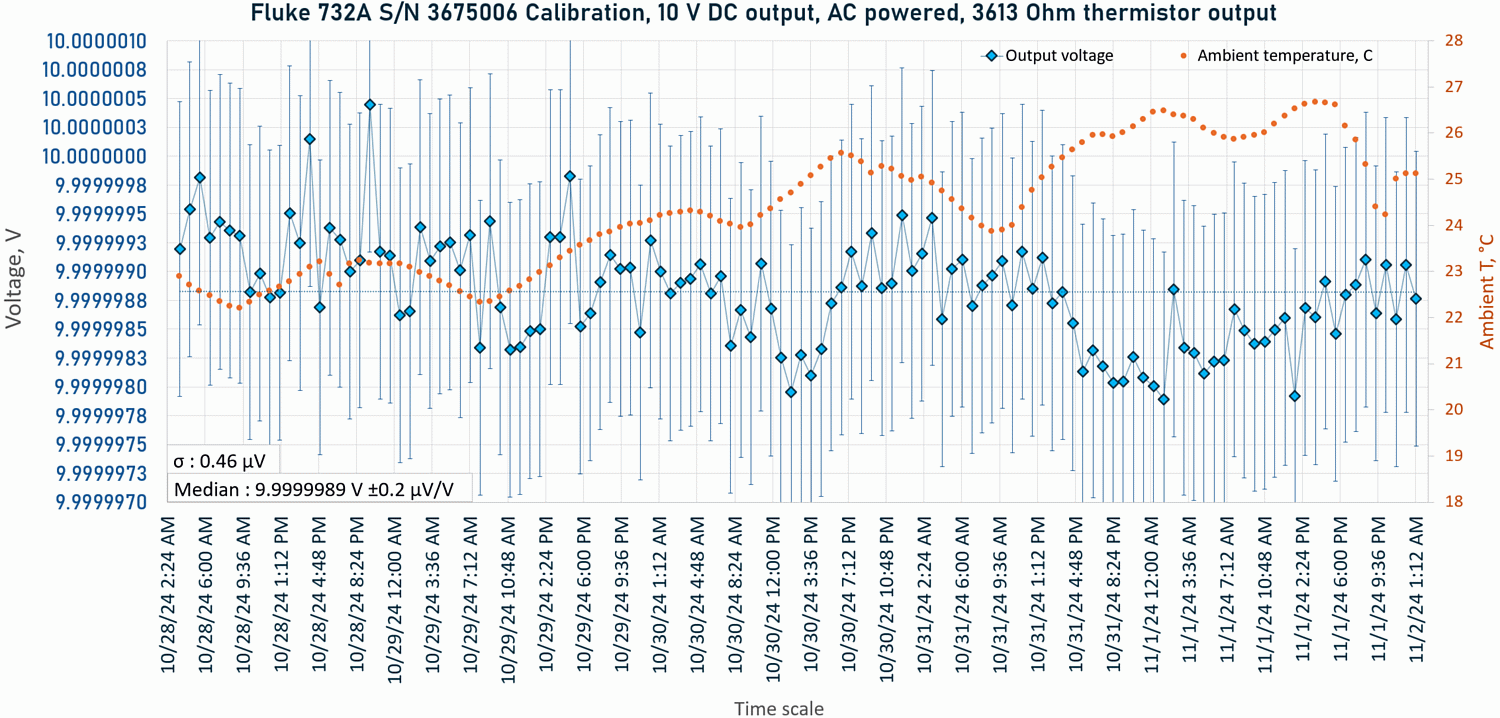
Image 30: Chart with all 10 V calibration points and uncertainties
Lab was a little bit warm lately as air-conditioning was turned off completely for the season. Lower divided 1 V and 1.018 V outputs were measured with freshly calibrated Keysight 3458A DMM using 15 minutes transfer spec. 1 V output was adjusted to nominal within uncertainty of the DMM. Final values for these outputs as listed in table 3 below.
| Date and time | Voltage calibration | Ambient temperature | Humidity | Pressure | Deviation from nominal | Specification limits |
|---|---|---|---|---|---|---|
| 10/28/2024 – 11/02/2024 | 9.9999989 V ±0.2 µV/V | +24.3 °C | 39.8 % | 1017.8 hPa | -0.11 µV/V | ± 50 µV |
| 11/02/2024 02:30:21 | 1.0000000 V ±0.6 µV/V | +25.14 °C | 32.6 % | 1014.2 hPa | Adjusted | ± 5 µV |
| 11/02/2024 02:32:36 | 1.0179801 V ±0.6 µV/V | +25.1 °C | 33.7 % | 1014.6 hPa | -19.5 µV/V | ± 50 µV |
Table 3: Final calibration results for Fluke 732A DC standard, S/N 3675006
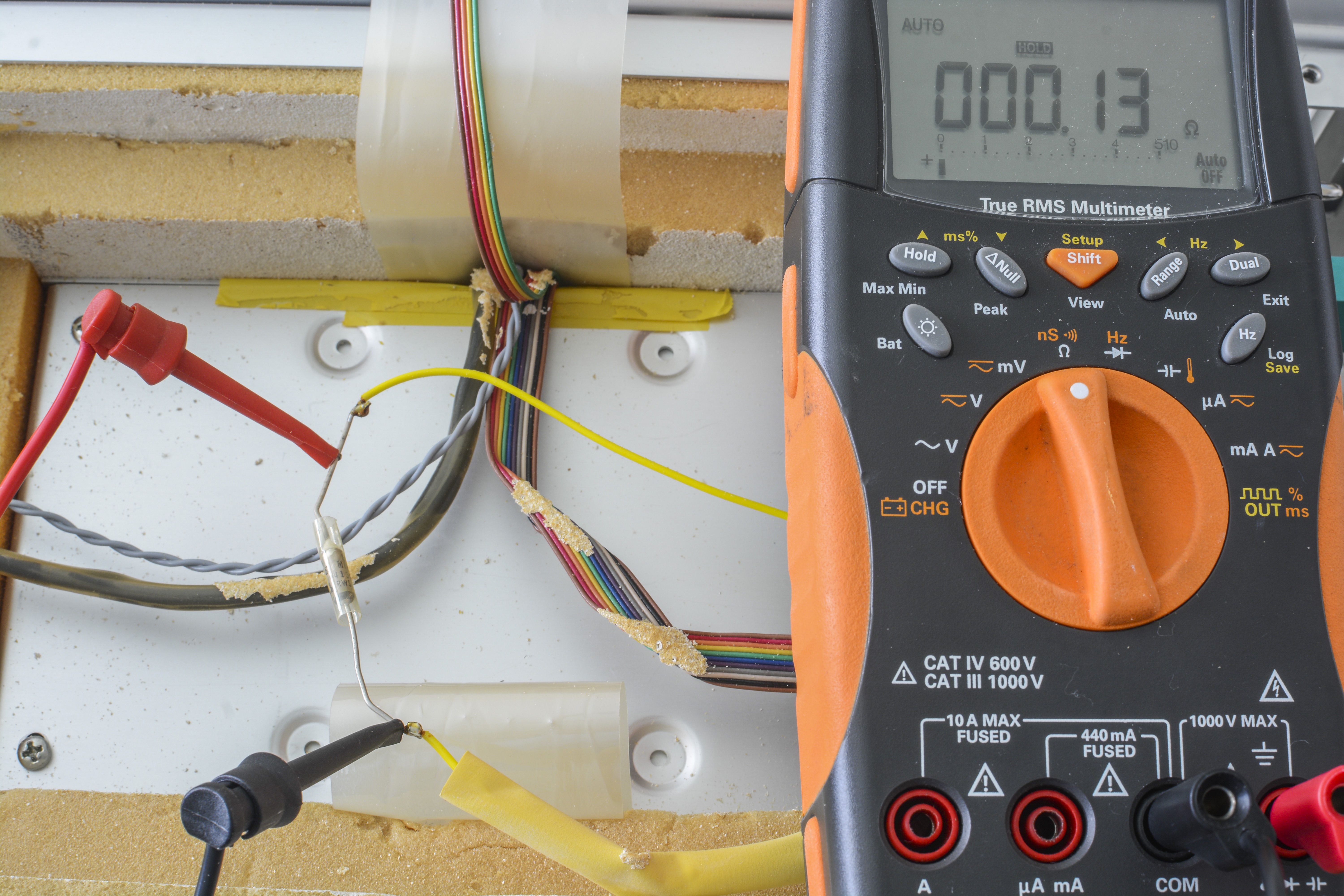
Thermistor output from the Fluke 732A front panel was reading on average around 3613.75 Ω with uncertainty of measurement ±6 µΩ/Ω.
This is quite impressive result for a repaired instrument that is more than 40 years old. Perhaps just another positive testament to the quality and stability of such old standard design. Granted, I don’t have any past knowledge if this 732A was adjusted by previous guardians or not.
Fluke 732A Design and construction


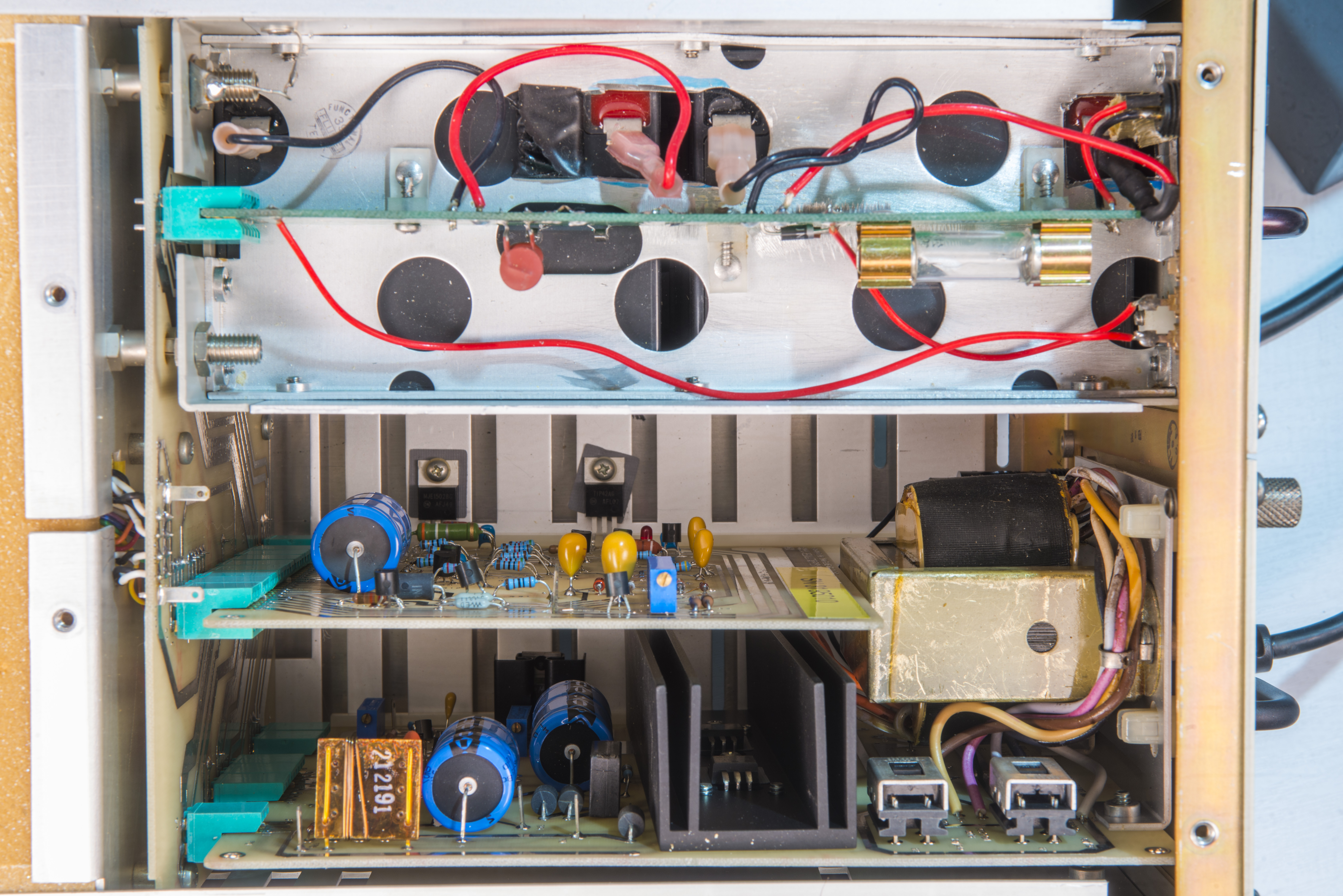
Disassembly and rest of the bits inside 732A


Reference oven PCB repairs and teardown


Fluke 732A using famous Motorola SZA263 Ref-amp hermetic zener-based reference core, while newer 732B and 732C use redesigned and refined version of ref-amp, designed and manufactured to this day specifically for Fluke instruments by Linear Technologies under part number LTFLU-1.
Repairs and refurbishment for the 732A
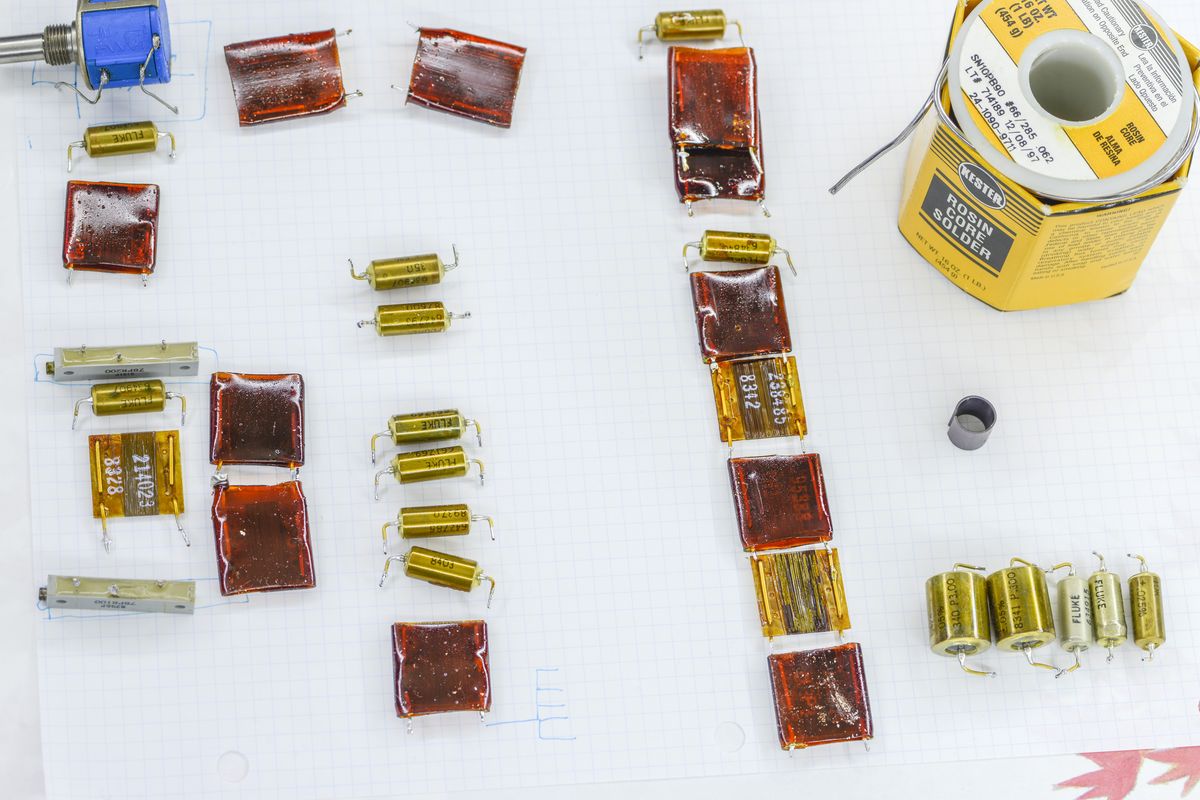
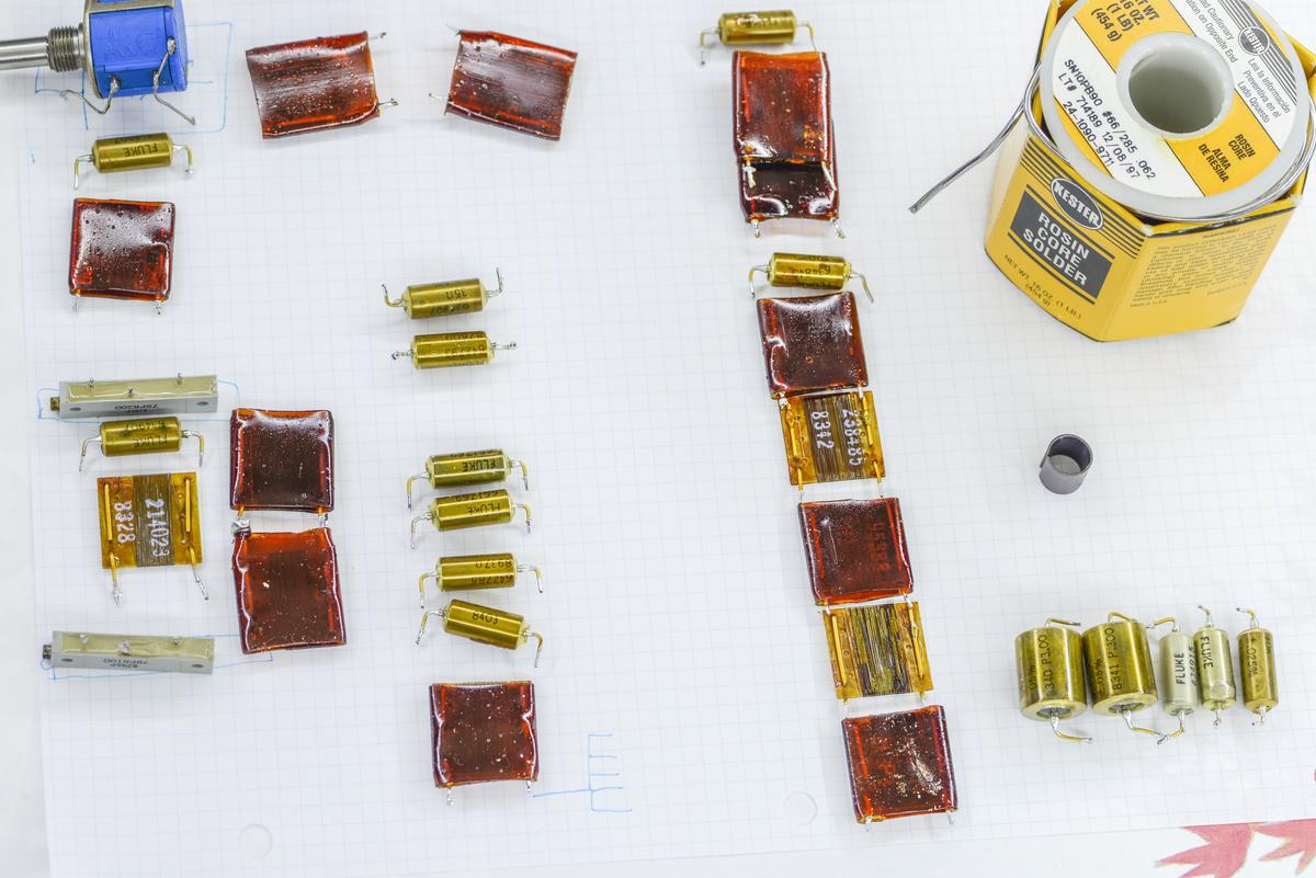
One of TIP transistors on power supply regulator card was cooking over +130 °C due to fault and wrong value resistors. It was obvious even without fancy thermal imaging from strong burn smell and heat radiated by massive heatsink.
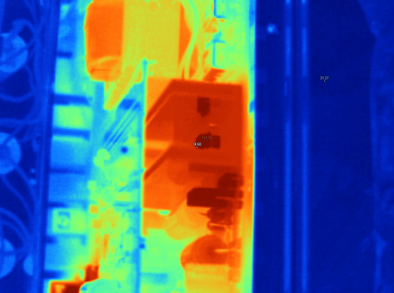
This issue was resolved by replacing offending transistor and all cabron composite resistors and electrolytic capacitors on both boards.
And collection of all replaced and bad parts from both 732As:
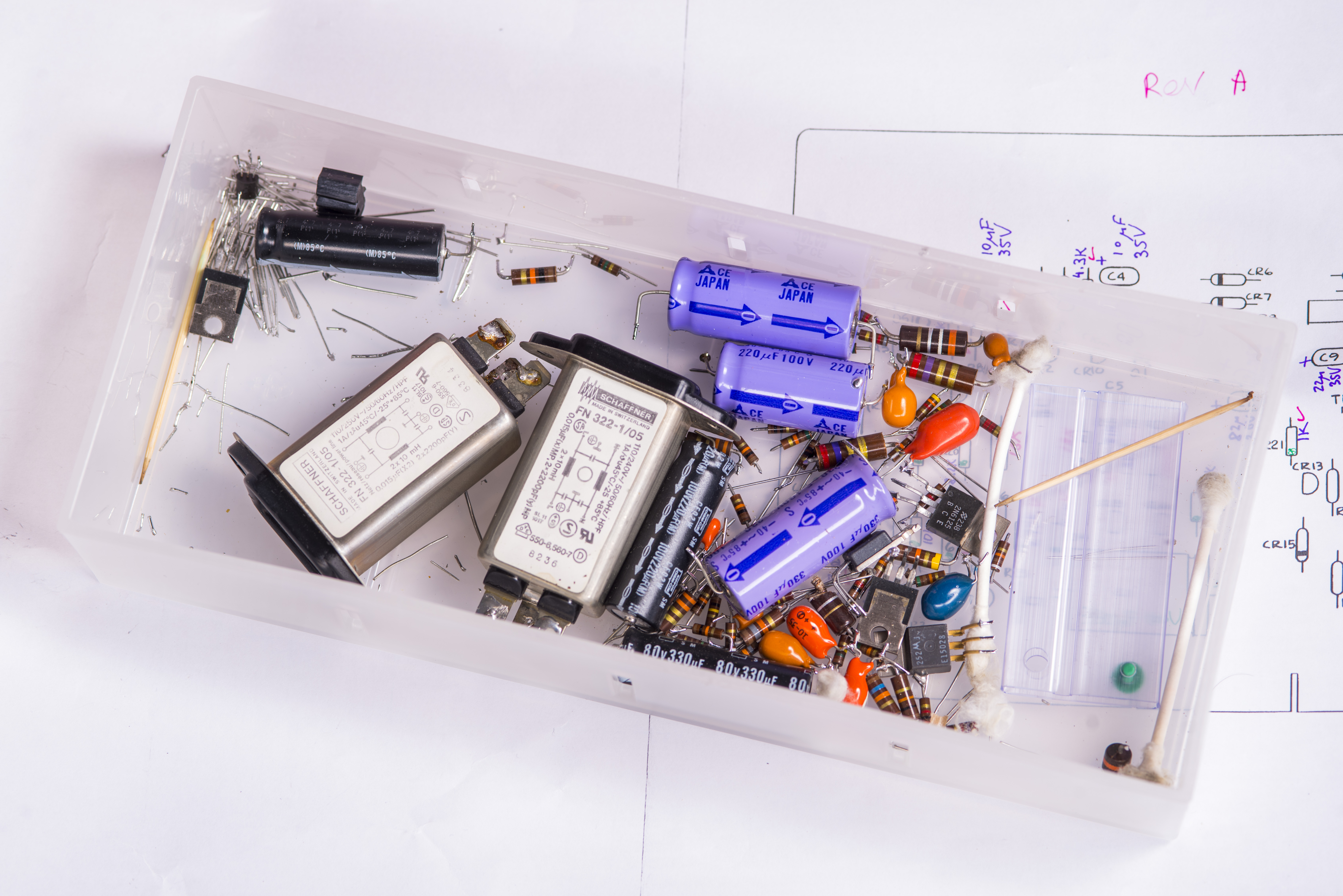
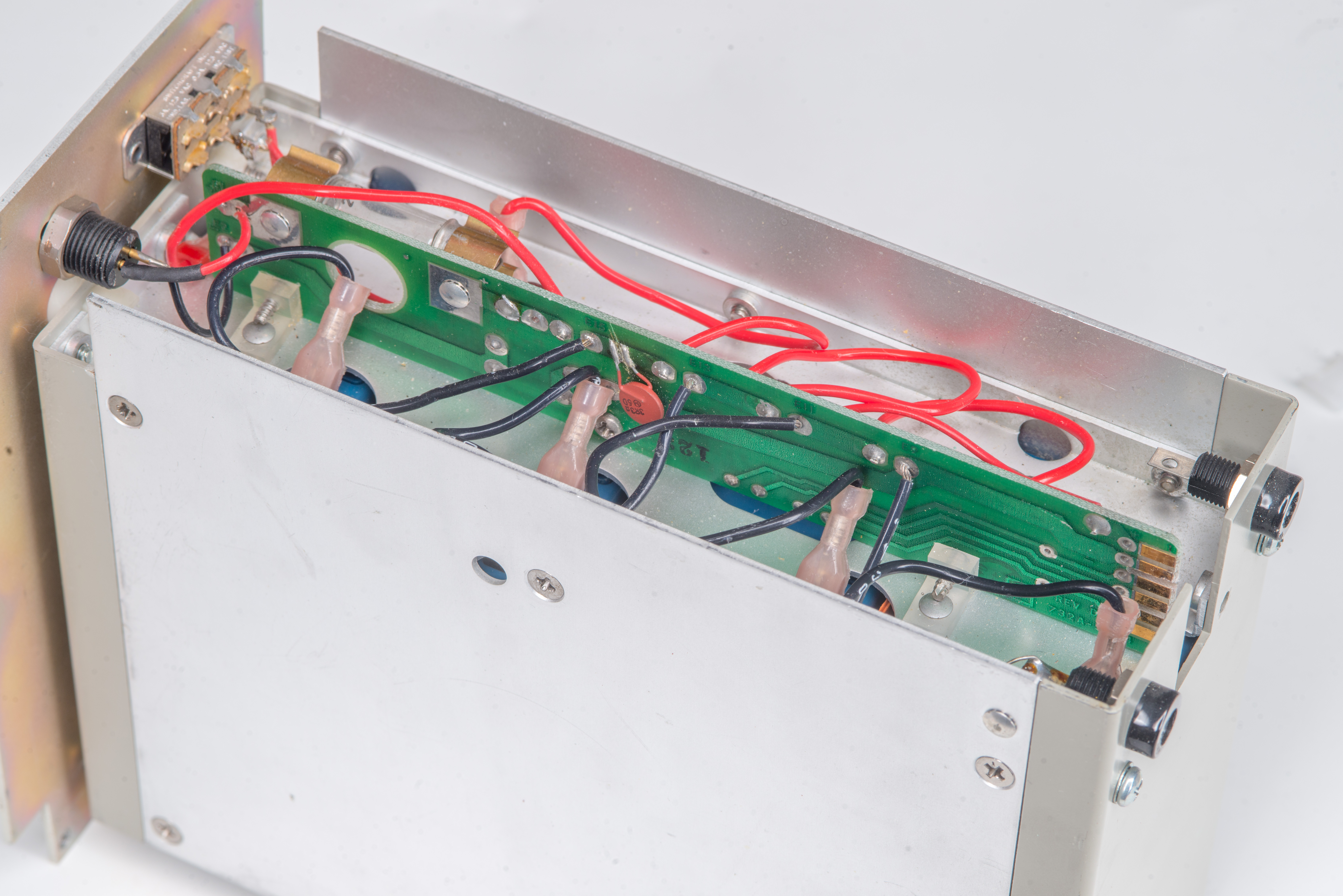
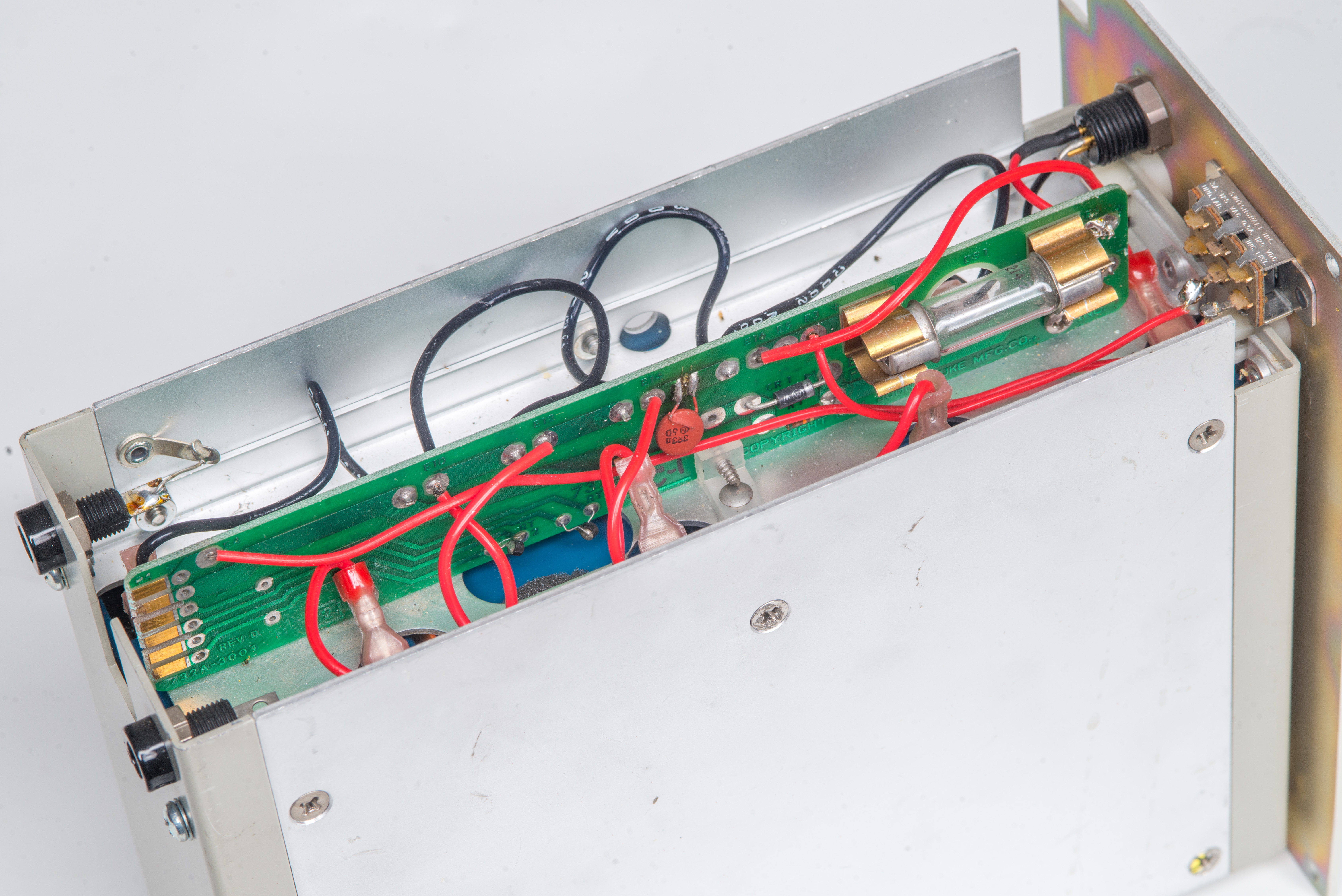
Replacement for front terminals on 732A
Poor standards had some rough handling by previous owners, as they were aquired from second-hand market.
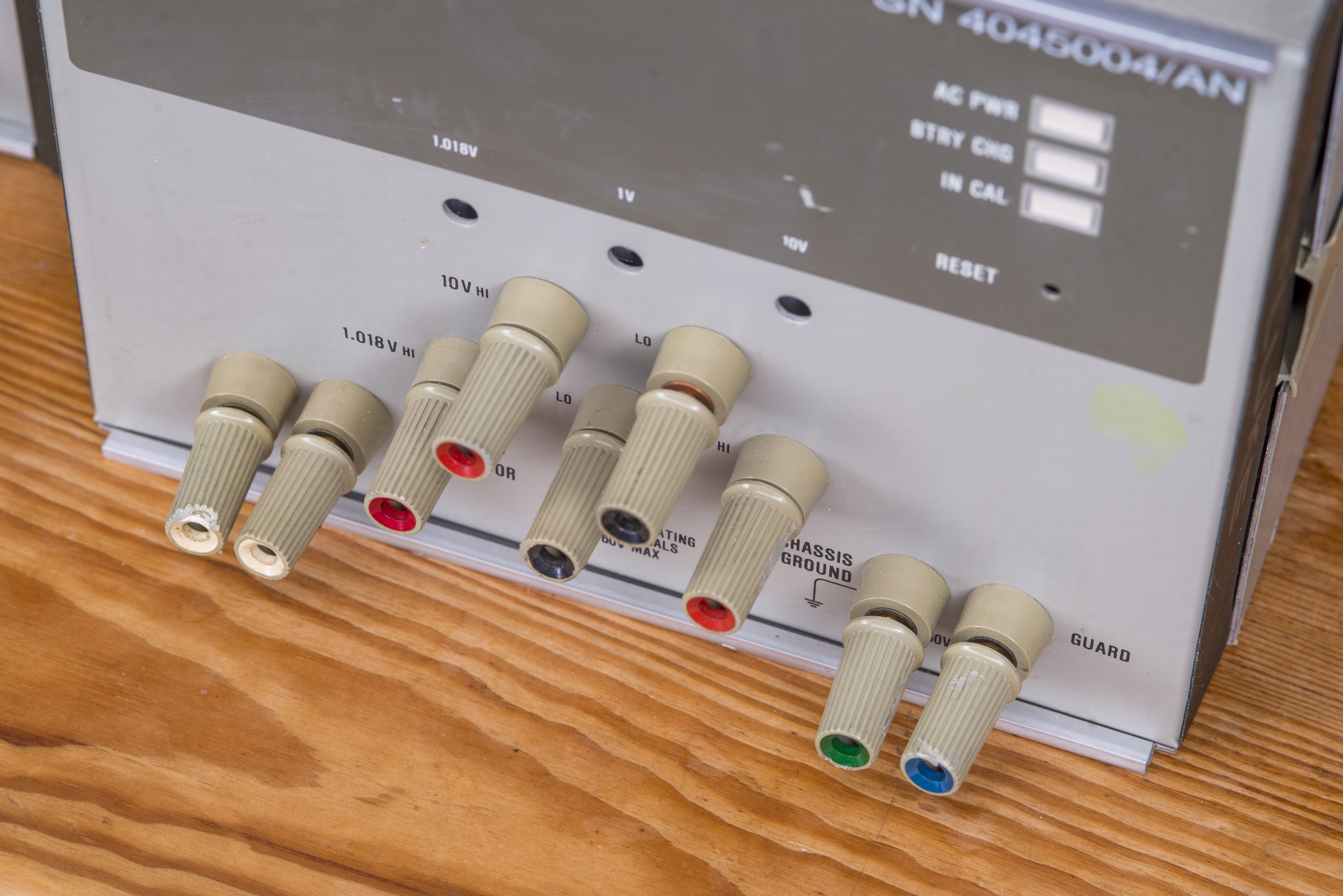
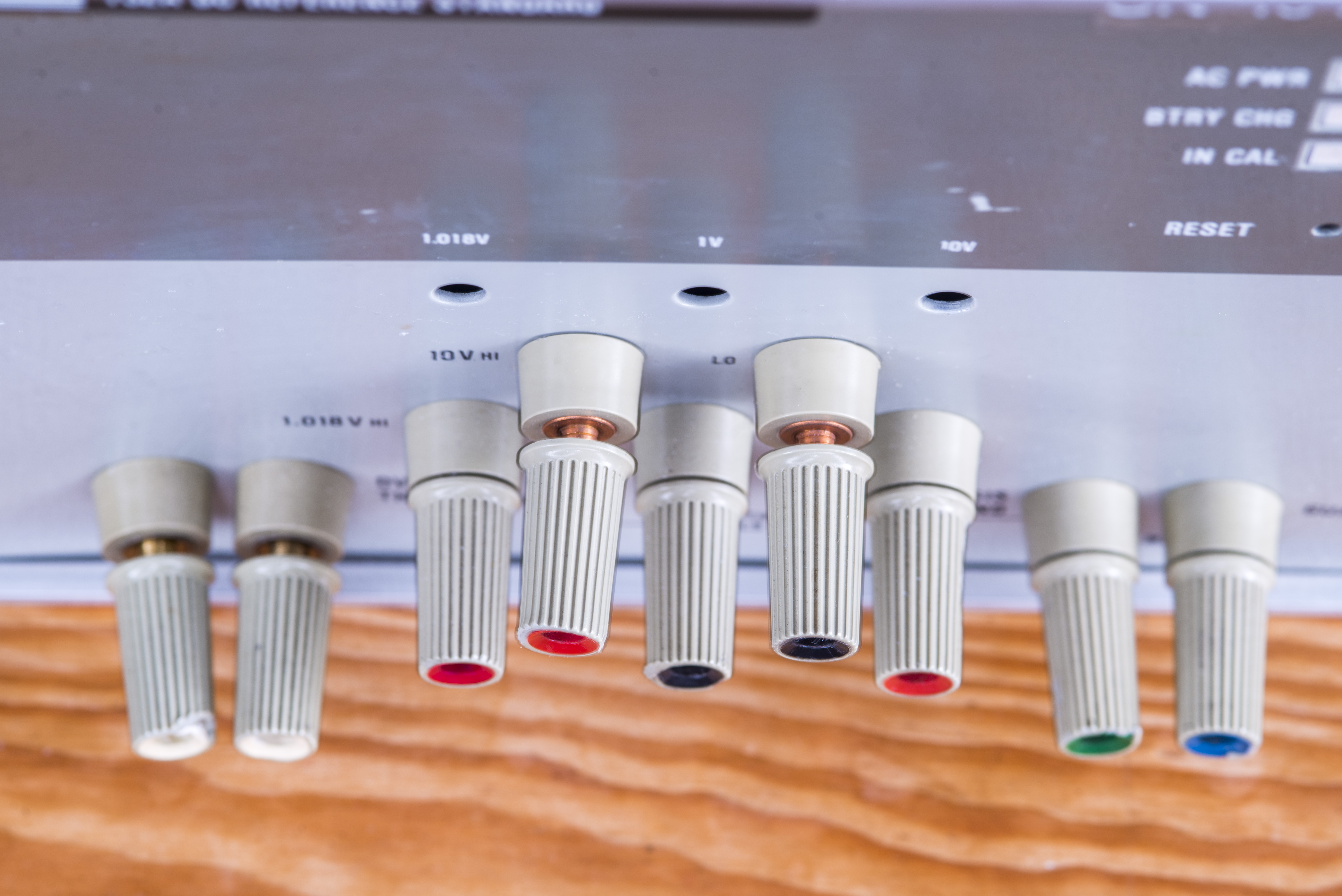
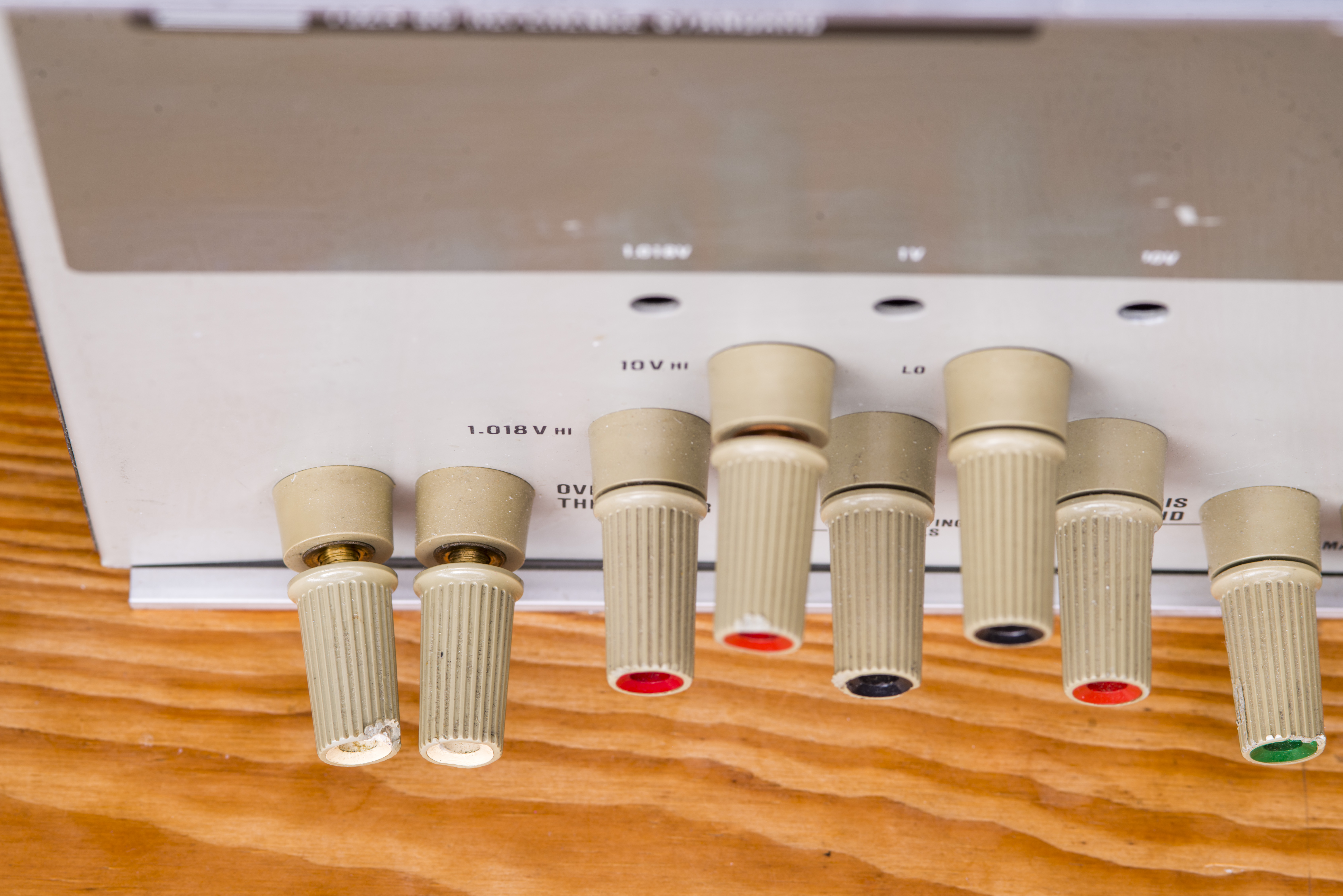
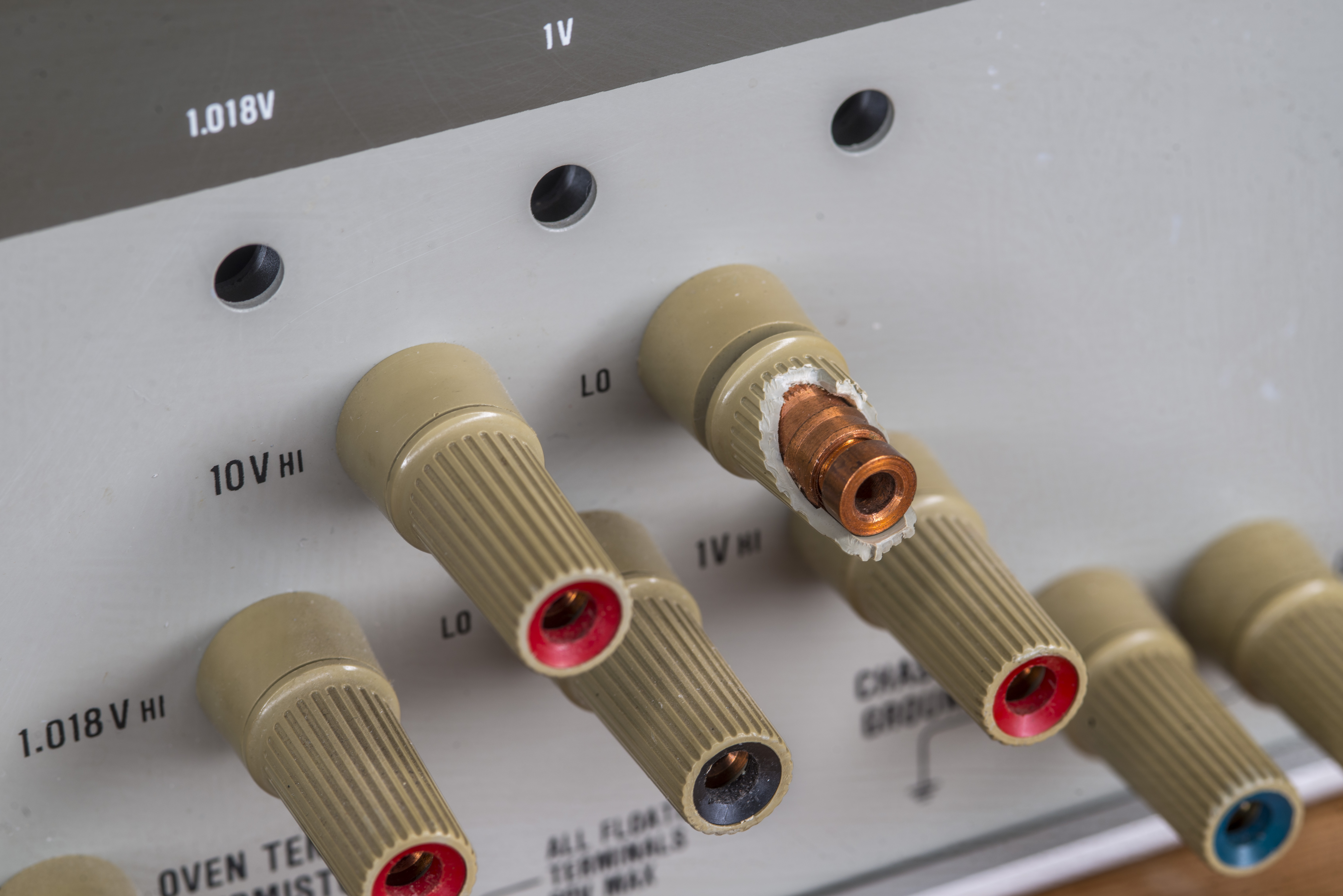
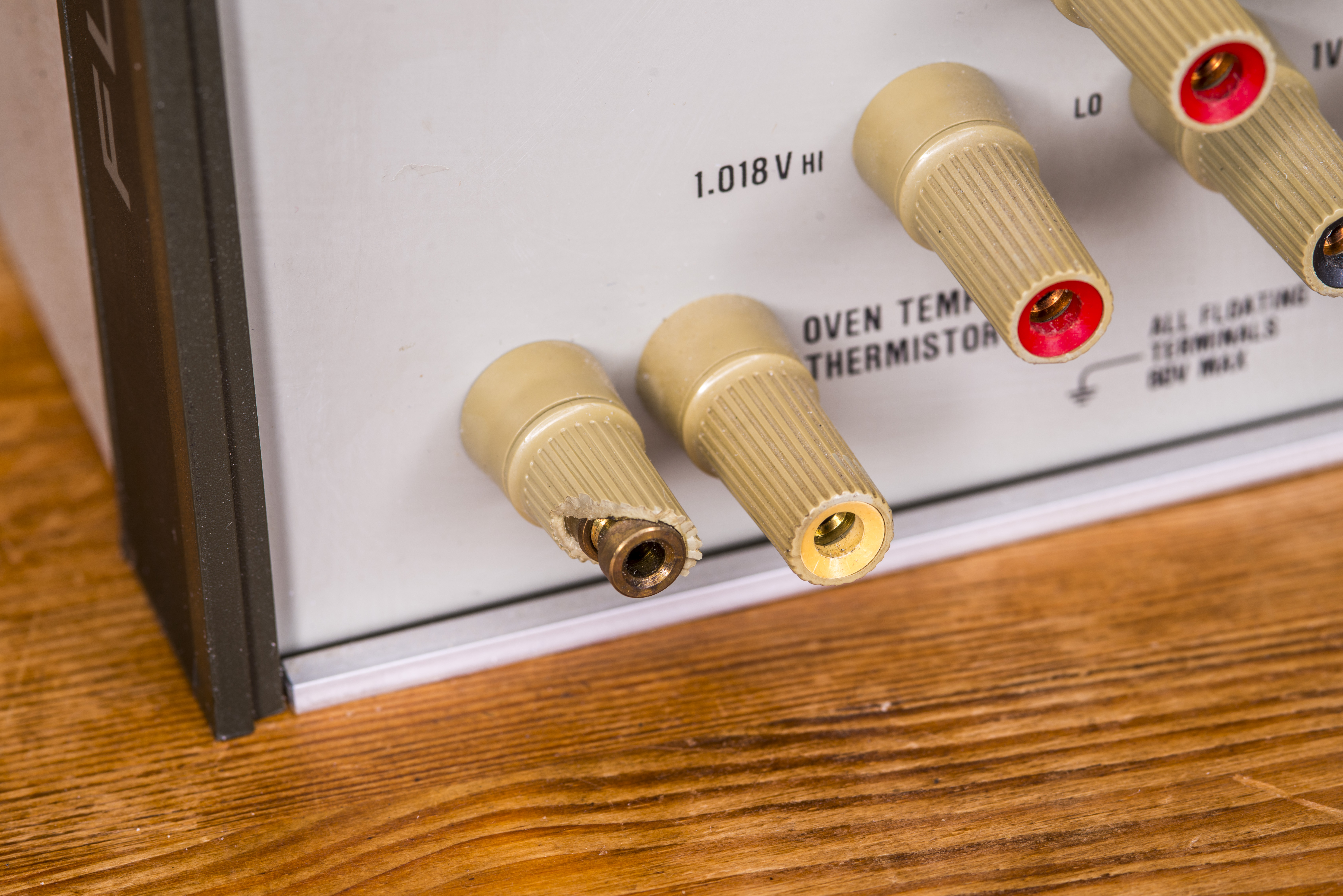
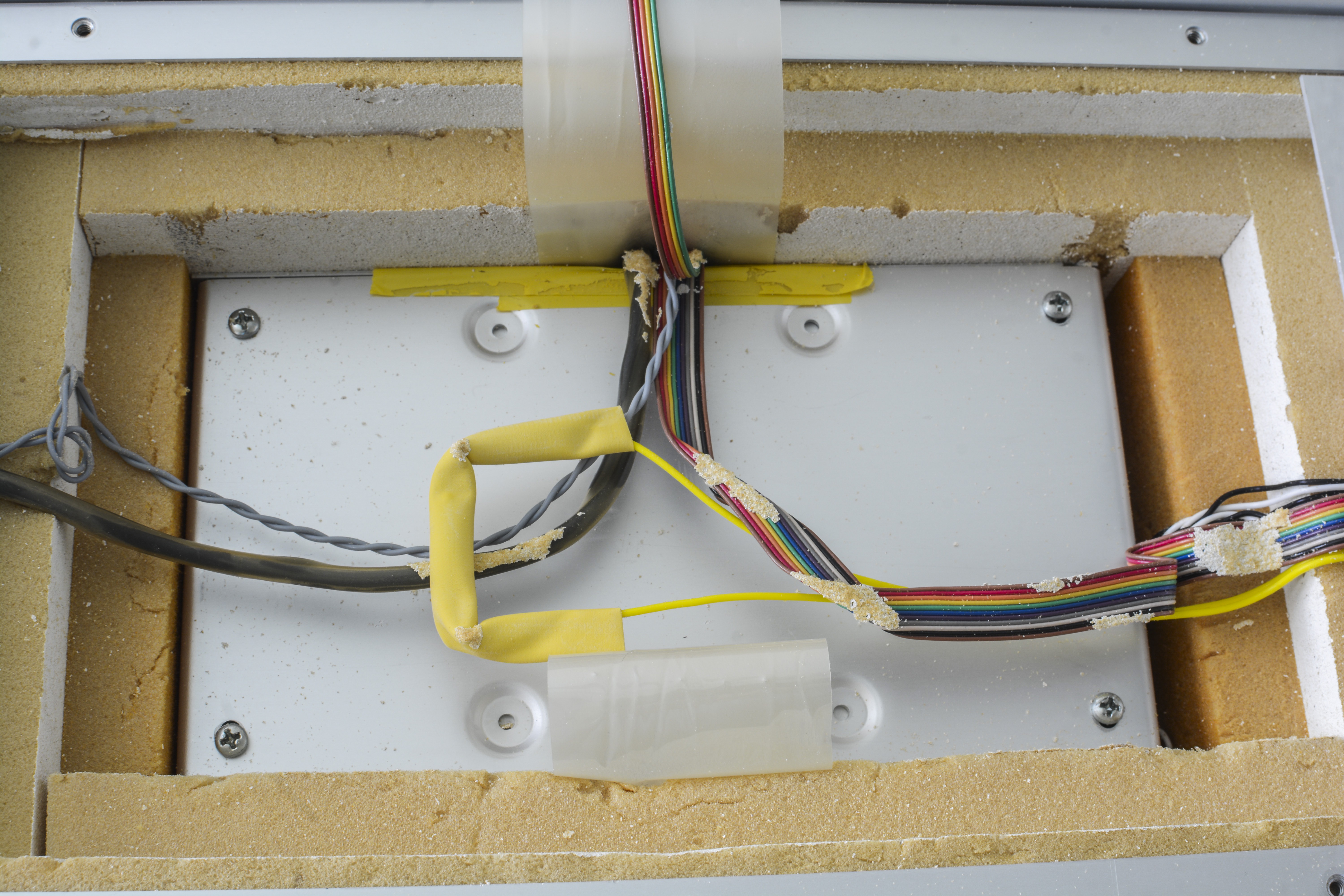
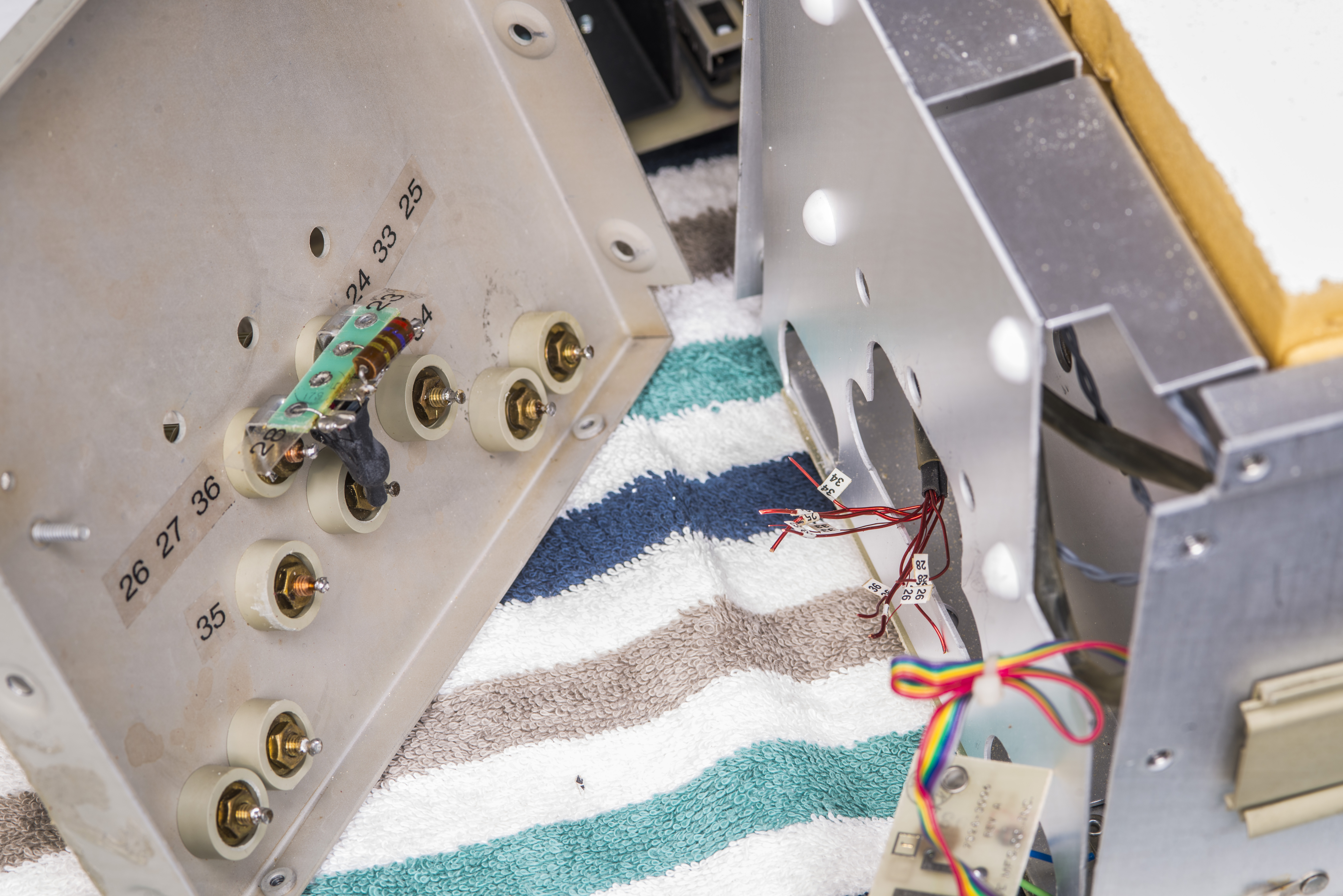
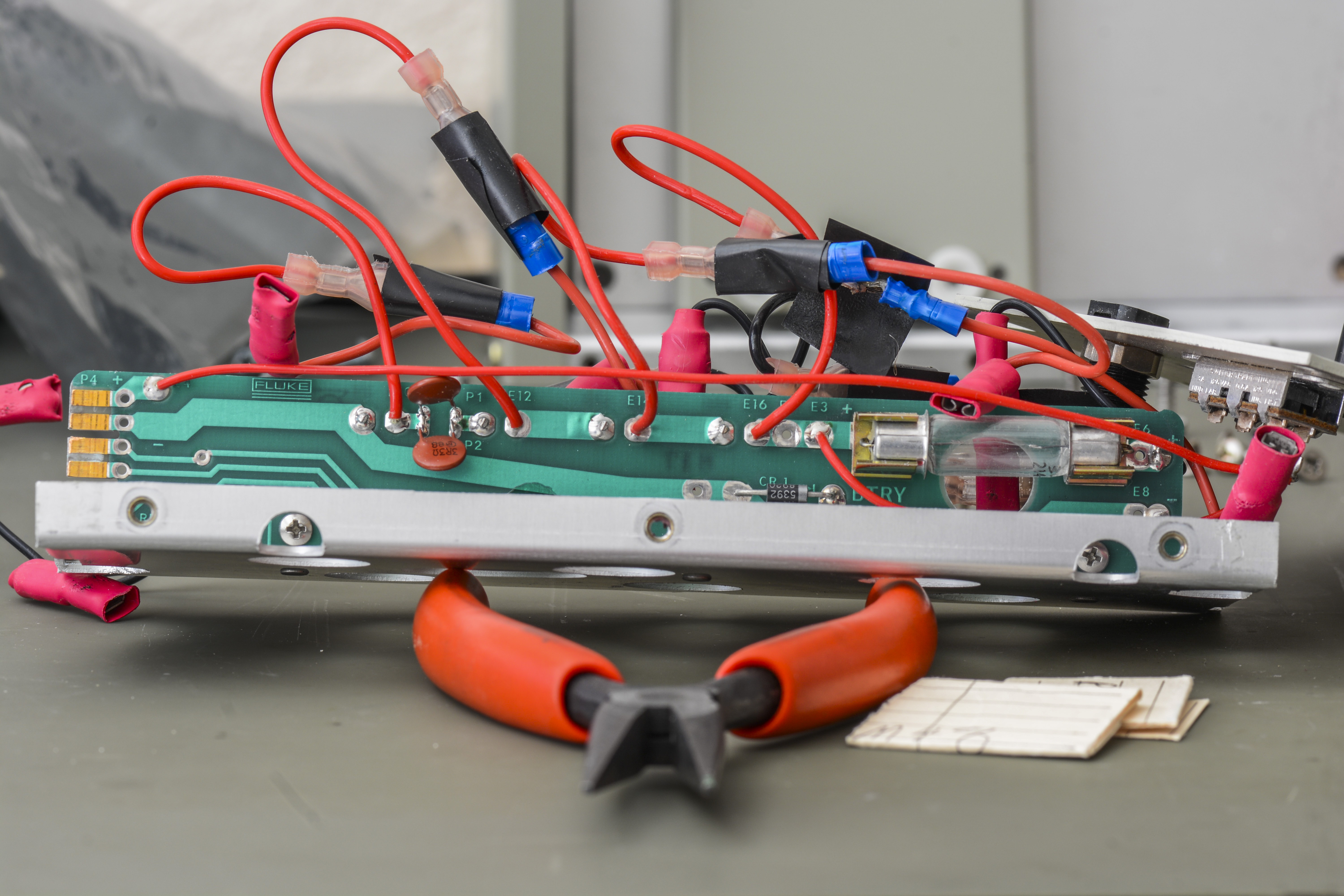
Replacing posts in theory is quite simple, but in practical implementation is a bit tedious because there are number of rigid copper solid core wires coming out of oven assembly and the length of this interface is just long enough to tilt front panel out. Each wire is carefully marked with identification label, but it is still little messy because there are number of sense wires, especially to 10V output terminals.
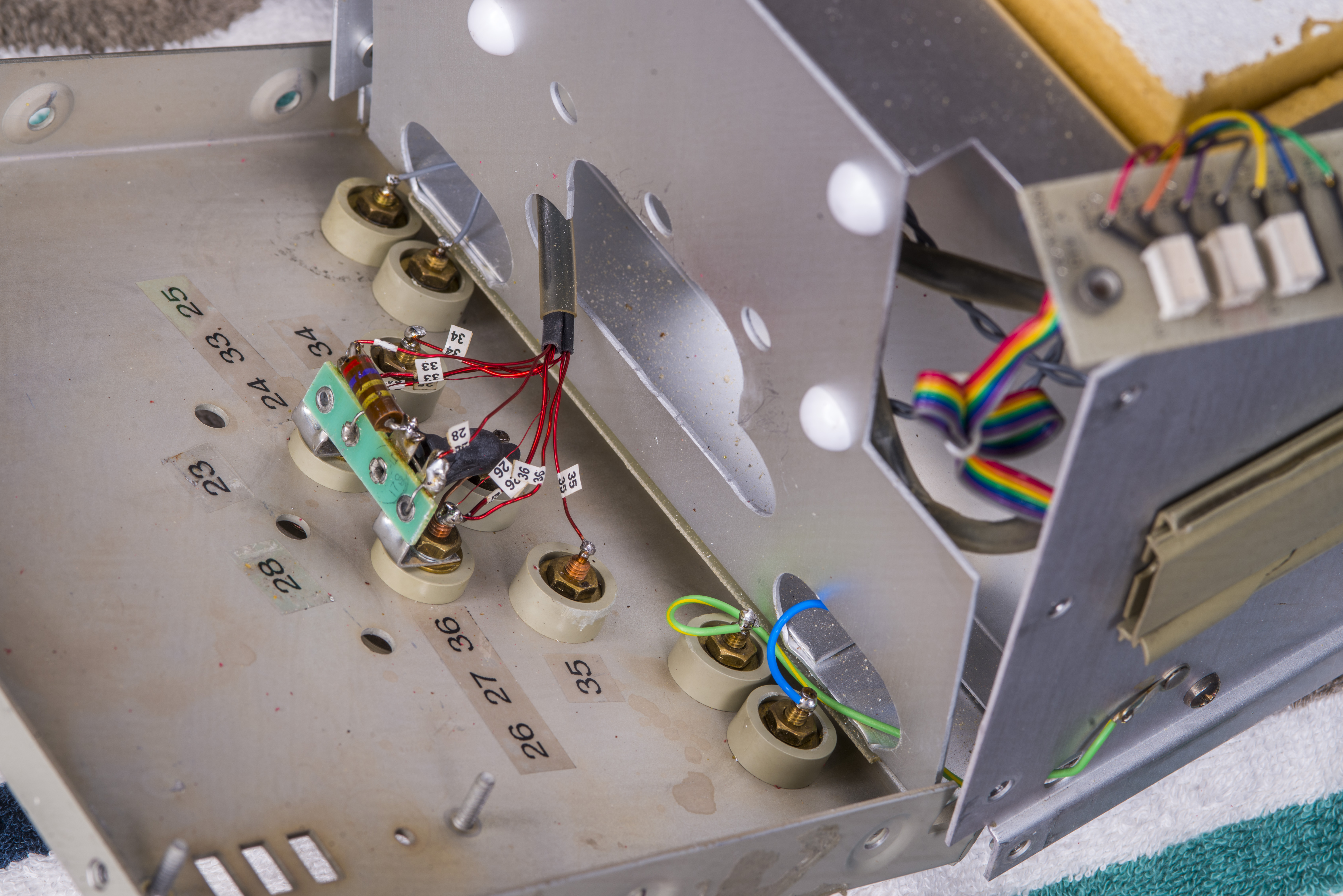
To replace post one would need to desolder the wire from copper post, replace the terminal, resolder stuff back in, hopefully not melting binding post plastic insulator in process. Using soldering iron with wide tip and plenty of power (80+ watts) is best in this case, to save on heating time applied to the terminal.
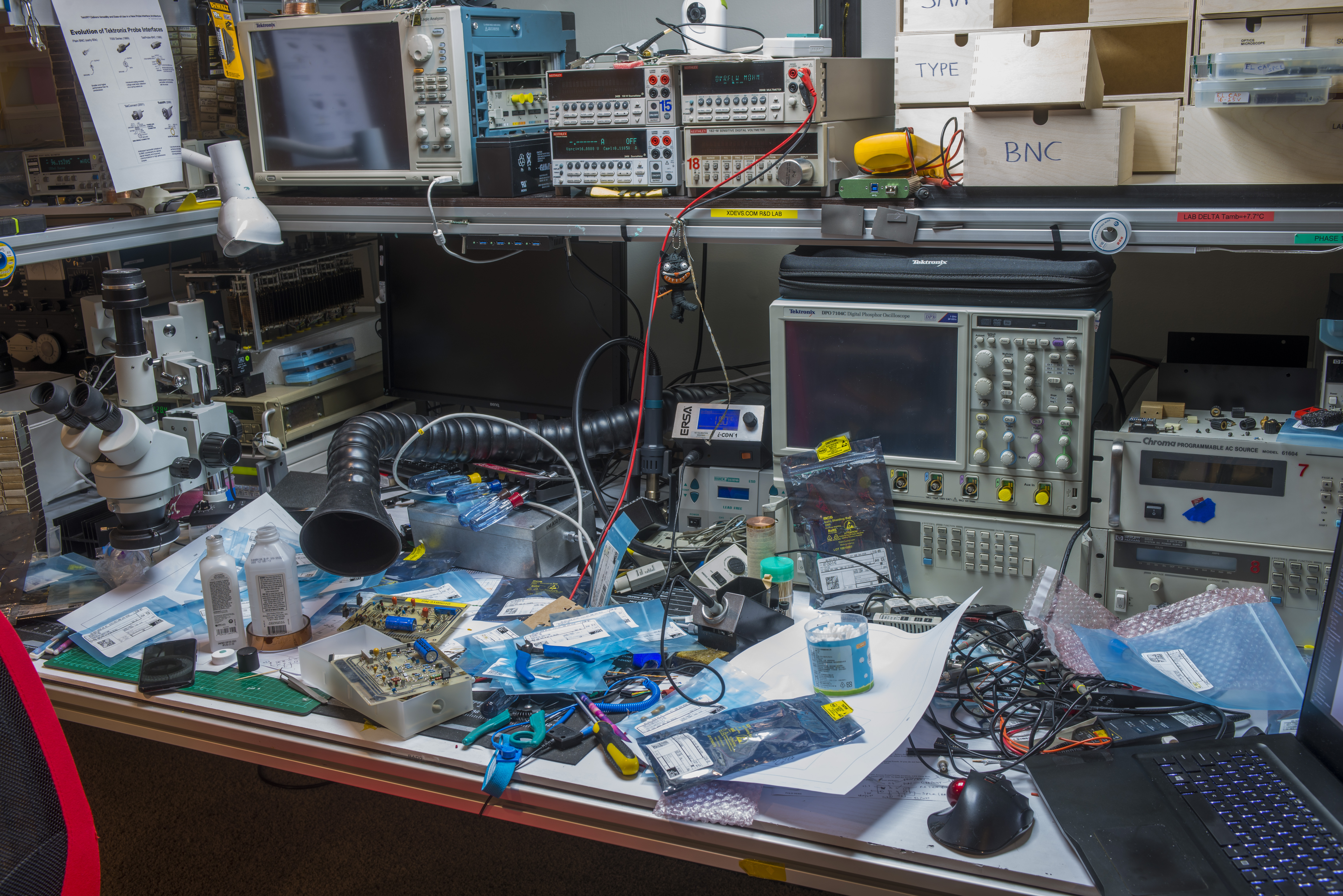
After reassembly and testing that all electronics in 732A work both units were intercompared and verified against other DC voltage standards.
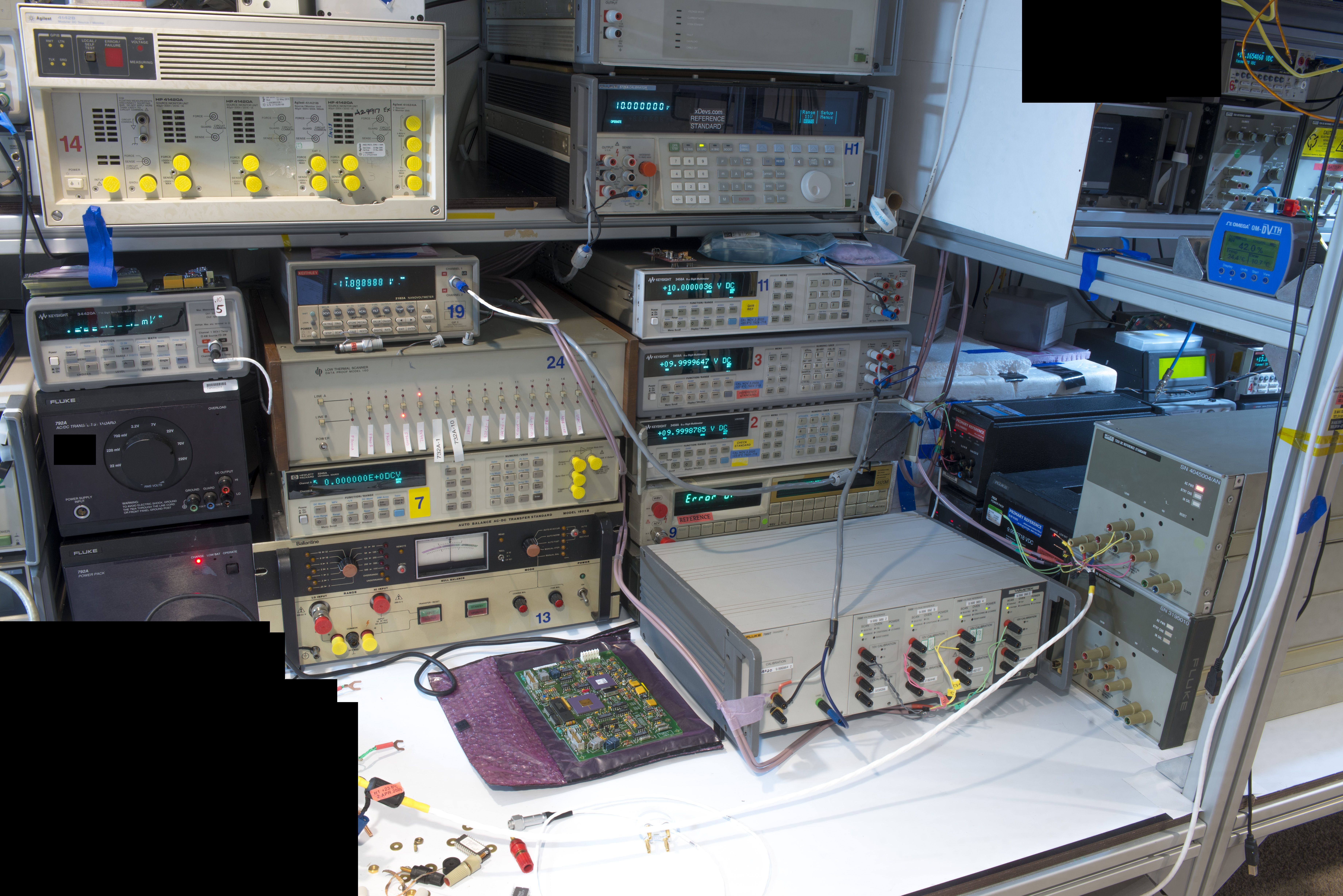
In photo above one such intercomparison is shown with 7 different zener 10V standards (Fluke 7004T, 732A, 732B and xDevs.com’s 792X) using Data Proof 160A nanovolt scanner and Keithley 2182A nanovoltmeter as differential detector with sub-ppm sensitivity.
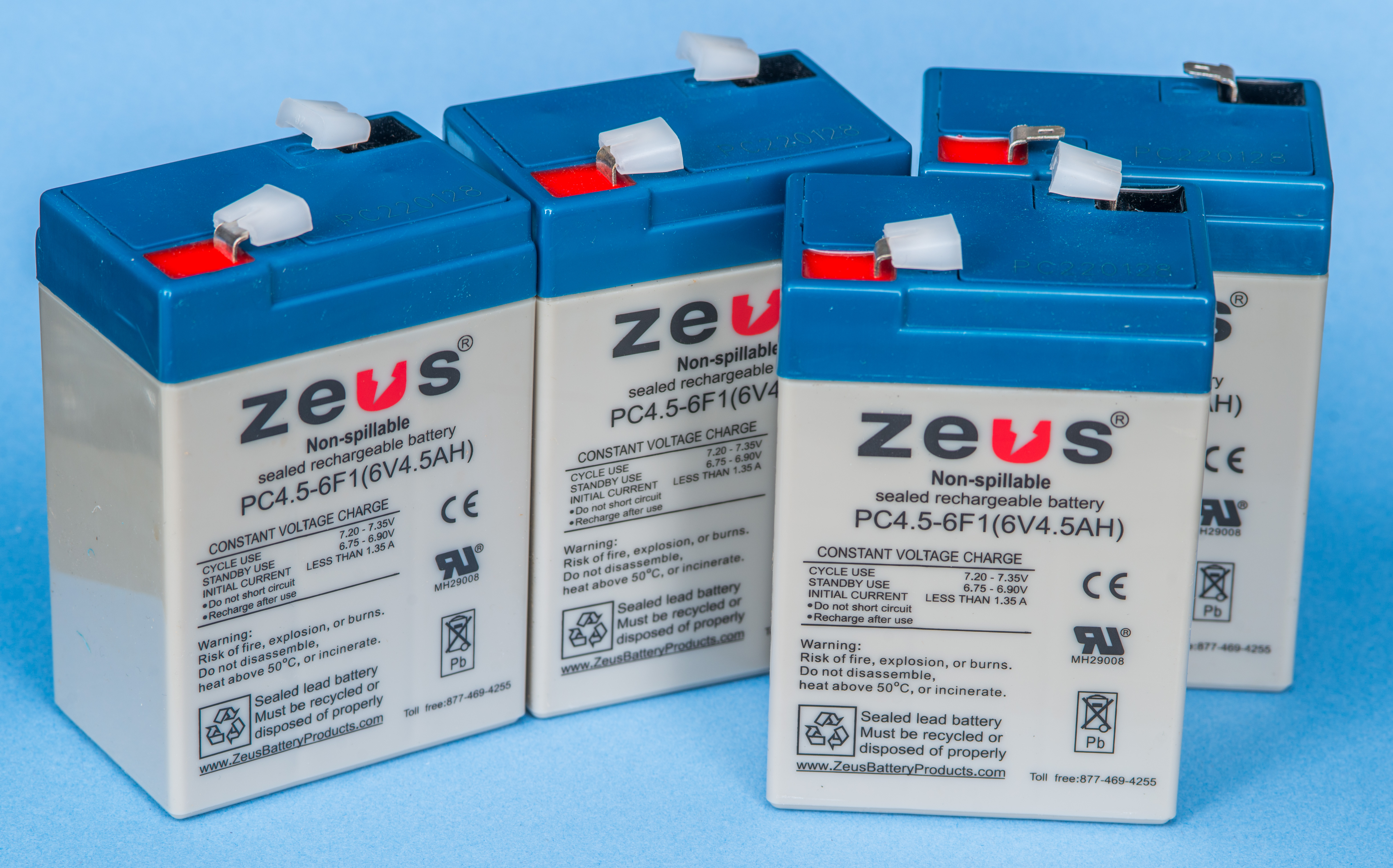
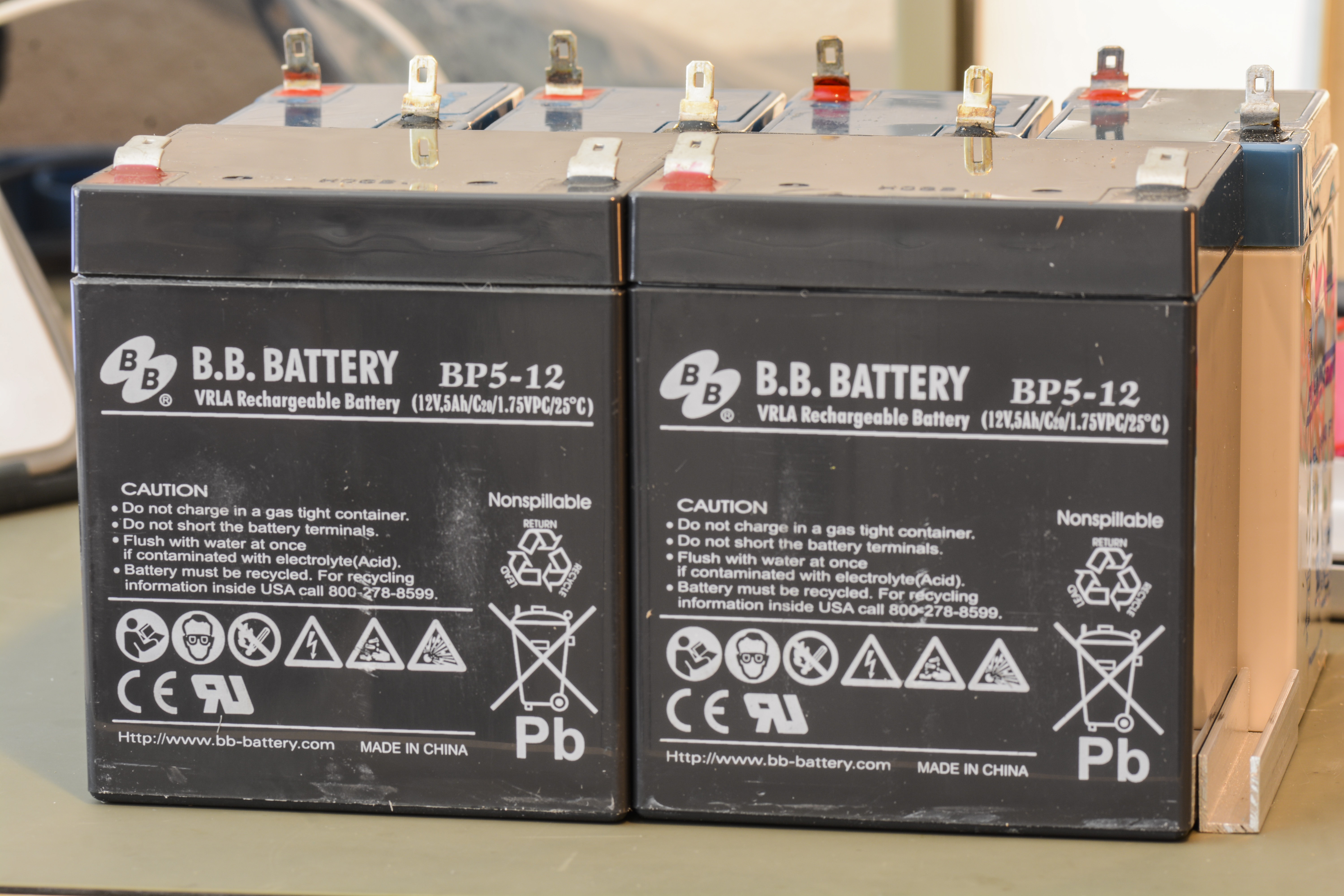
Battery replacement using 4 × 6V 4.5Ah VRLA for 732A
Simplest way to replace old dead batteries in Fluke 732A is to source four suitable 4.5Ah 6VDC lead-acid batteries. One of such examples is these from DigiKey for $15.76 USD/pcs. They are rated for floated voltage at +6.90V, which is lower than old original 732A batteries.
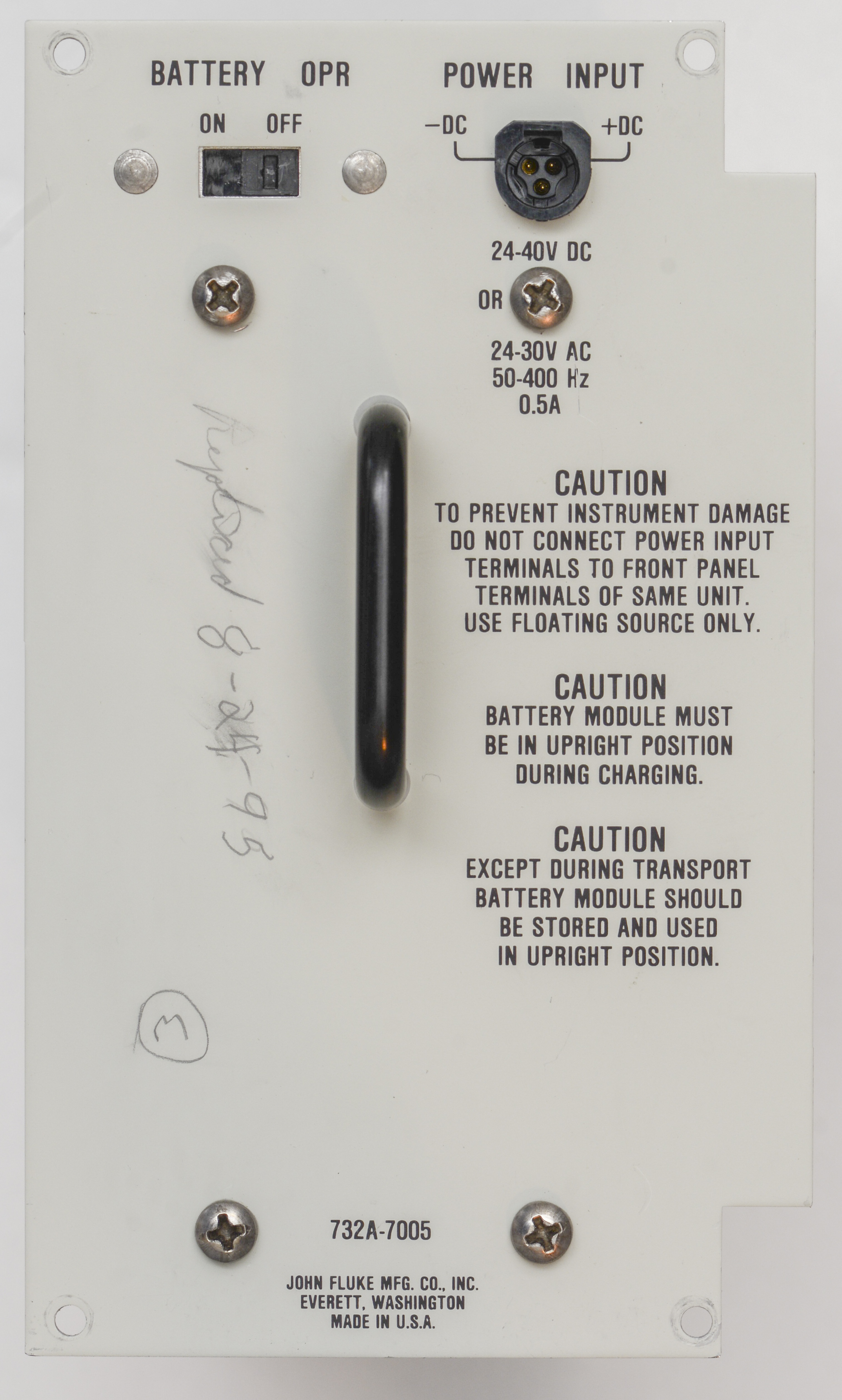
Charge floating voltage level in 732A can be adjusted by R20 potentiometer on A4 PCBA (one with transformer and pre-regulator circuitry). Without this adjustment 732A will cook new batteries pretty fast, destroying new pack in a year or so.
Installation takes about 10 minutes. Disassemble frame, remove old batteries, and install new ones on plate. Bend battery terminals to about 60° angle for easier cable connections. Then carefully drop top metal frame with holes for terminals, without shorting any terminals to metal plate.
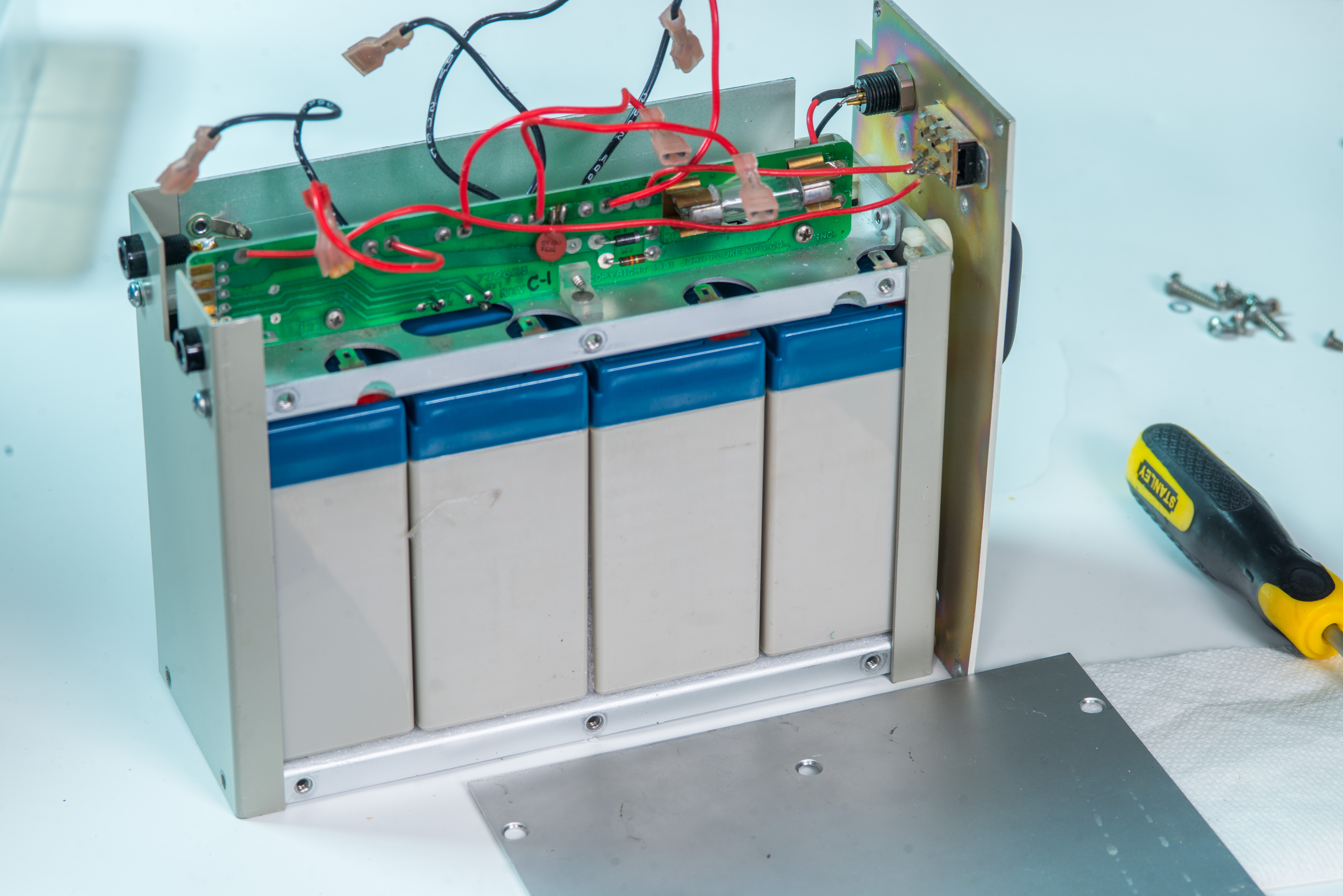
Connect all red wires to positive terminals on battery pack and black wires to negative. Keep order like original. Output voltage at positive and negative pad of interconnecting PCB should be around +26 VDC for new batteries with good charge.
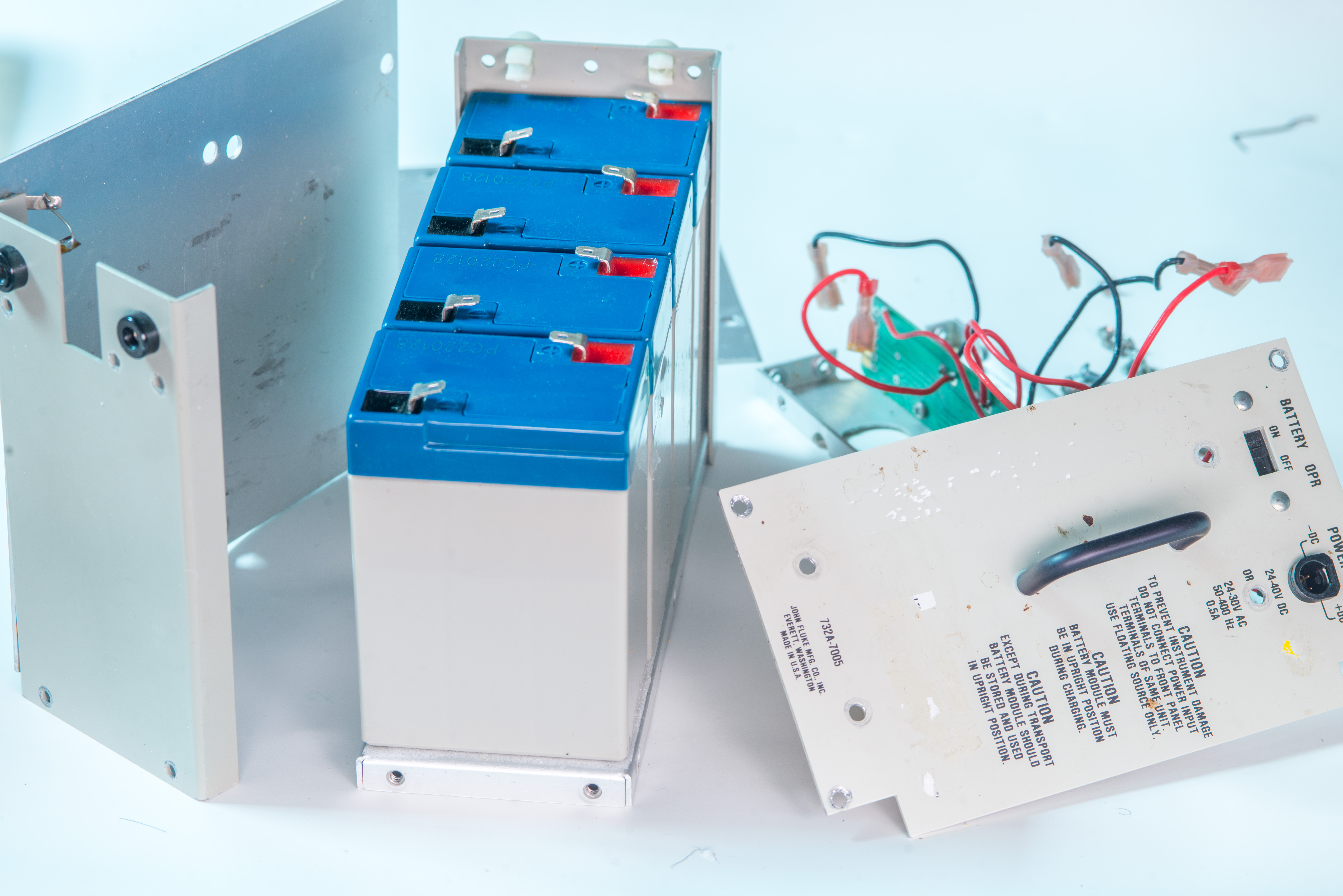
Now pack is ready to install in the unit.
Should be good for 3-5 years of lifetime in normal metrology lab conditions.
Battery replacement using 2 × 12V 4.5Ah VRLA for 732A
Another alternative for battery pack rebuild is to install two larger 12V rated lead-acid batteries. This require some additional cutouts for the top metal work to allow safe terminal exposure and wiring.


Fluke 732B Design and construction
xDevs and friendly labs also have number of more modern and much smaller Fluke 732B DC Voltage standards. They are smaller and more refined version of large and deep 732A but provide essentially same functionality and performance.
Compared to 732A thermistor output and earth chassis 5-way binding post terminals are no longer available on front panel. Instead thermistor is routed to DB9 port on the back of 732B and earth chassis connections provided by screw near mains receptacle input.
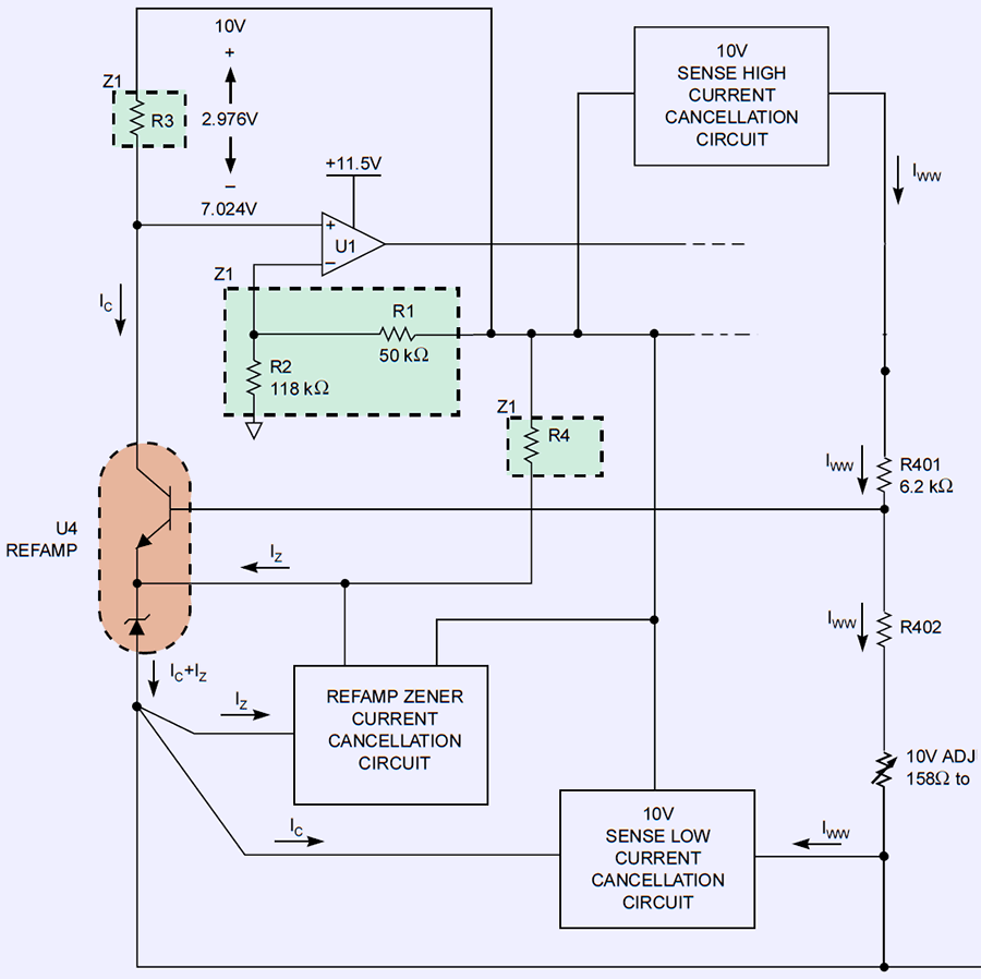
Overall reference schematics is rather simple:
732B units repairs and teardown
Let’s dig deeper, towards the zener reference oven core.
Fluke 732C Design and construction
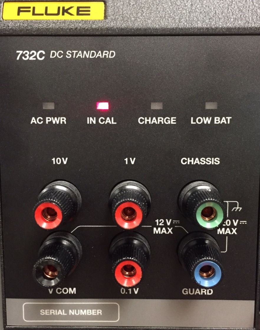
Fluke launched refresh DC standards line and released new 732C on June 26, 2018 These new units under model 732C are the latest reincarnation of Fluke 732 standard series. It replaces 1.018 VDC output with 1.000 VDC output and instead of second return 0 V post adds divided 0.1 V output. Both 1 V and 0.1 V outputs are provided from resistance passive voltage divider and support only high impedance loading.
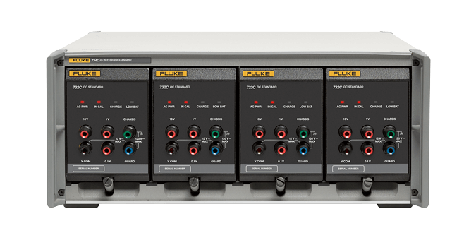
Four-standard enclosure mainframe is also refreshed to new Model 734C but it has no physical design changes, other than now cheaper yellow Fluke label on front. 732C’s can be installed and work in old 734A enclosure just fine.
There are few more internal changes in 732C design compared to predecessor 732B but all specifications and operation procedures are otherwise identical between these two units. Core of the 732C is still based on good old Linear Technologies LTFLU-1ACH refamp zener core. Performance specifications and procedures to calibrate are identical to older 732B units.
Here are some exclusive additional photos of Fluke 732C DC Voltage standard unit, showcasing key elements in it’s updated design. This particular 732C was received by xDevs for a repair service for a friend. So I can use this opportunity to take apart the instrument and document it’s internal construction for all of you. Let’s start with a power supply/charger assembly. Charger PCBA has some small changes compared to 732B design.
There is additional internal switch SW503 located near REF01 reference IC, implemented to disable voltage regulator for the reference core. This feature added to save some battery power when this PCB is installed in charger power pack 732C-7001 module, which does not have zener reference core.
Interesting to note that PCB design have date code 2016. So it took Fluke about two years from design win to actual product release, which is pretty quick for a demanding product like 1ppm/year capable DC voltage reference.
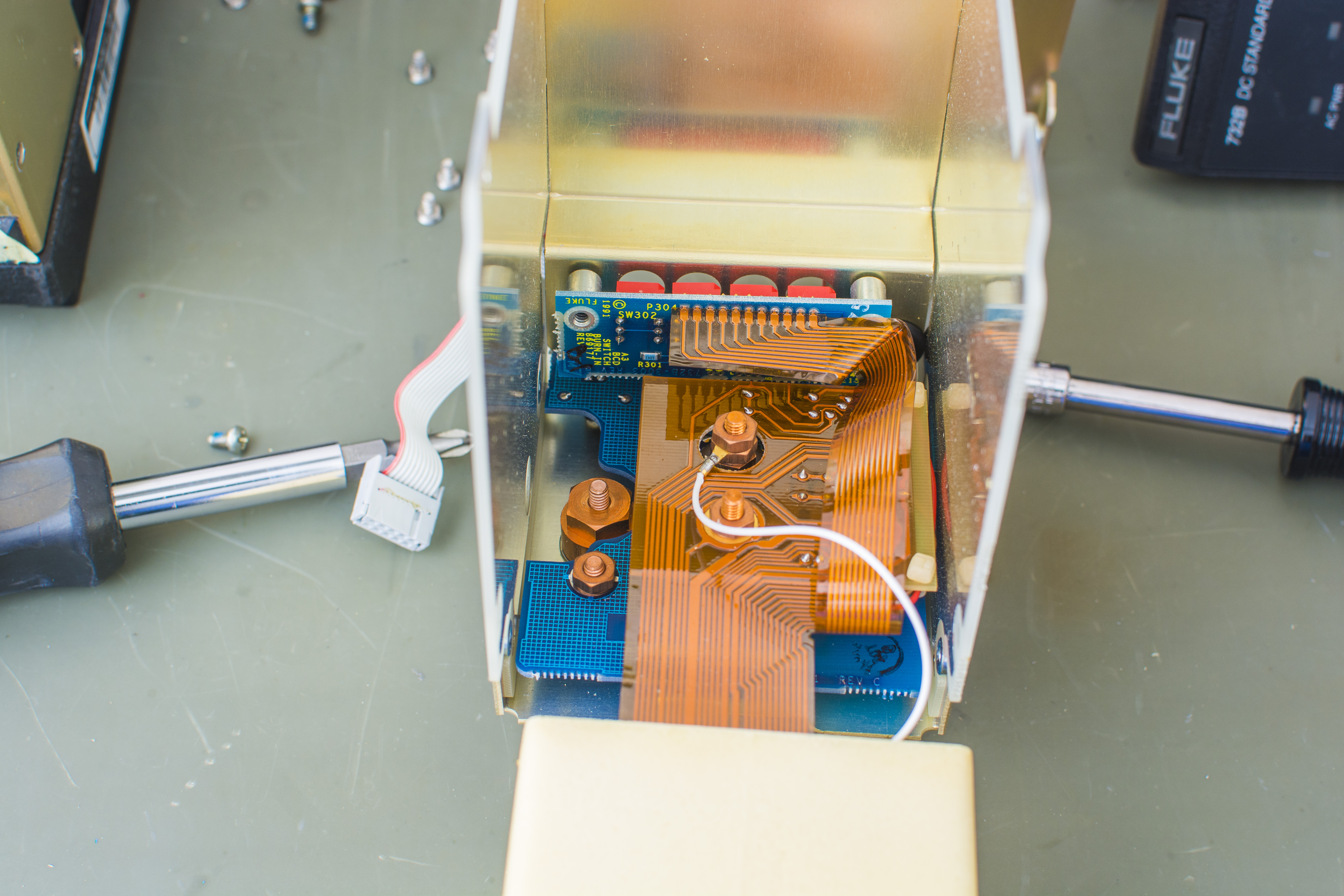
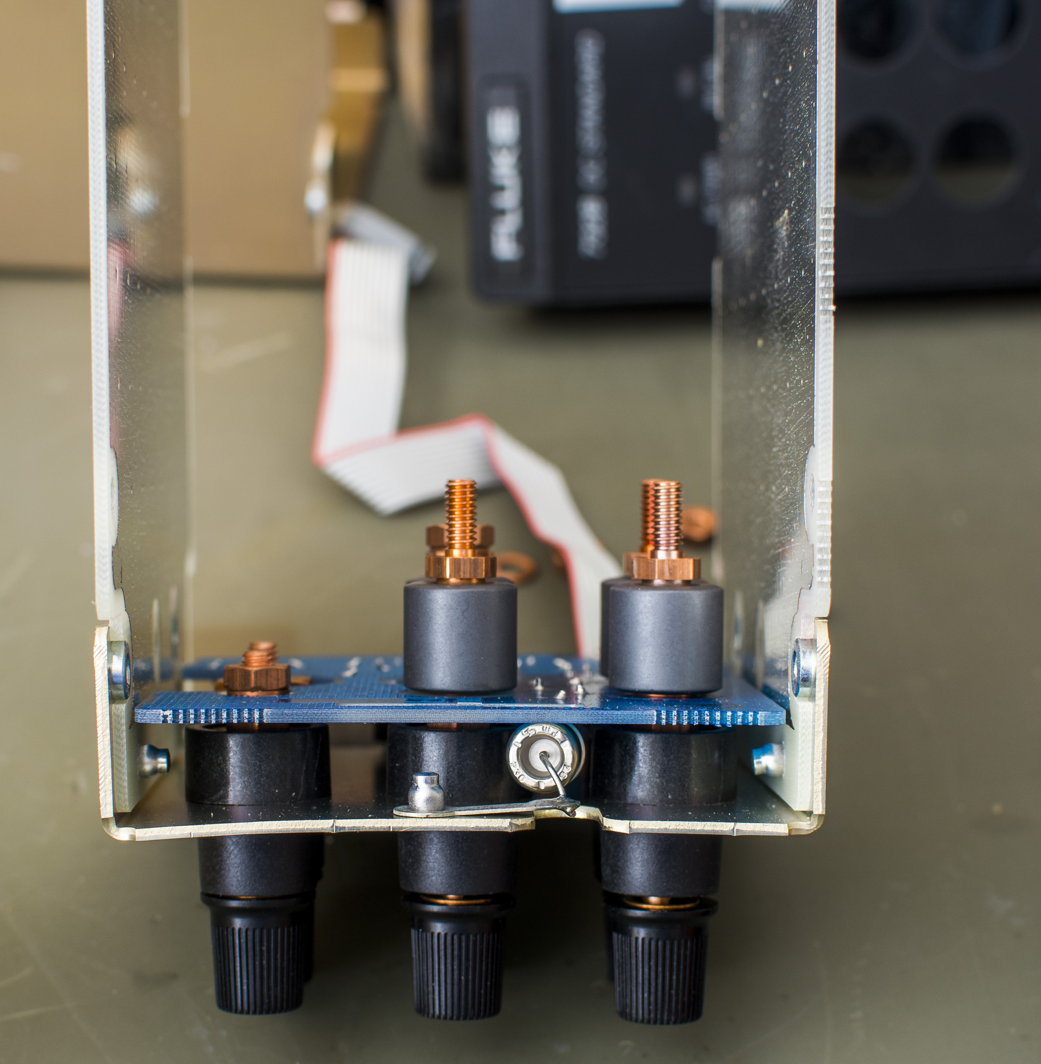
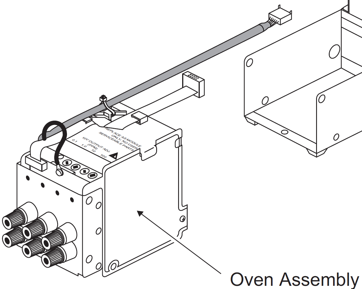
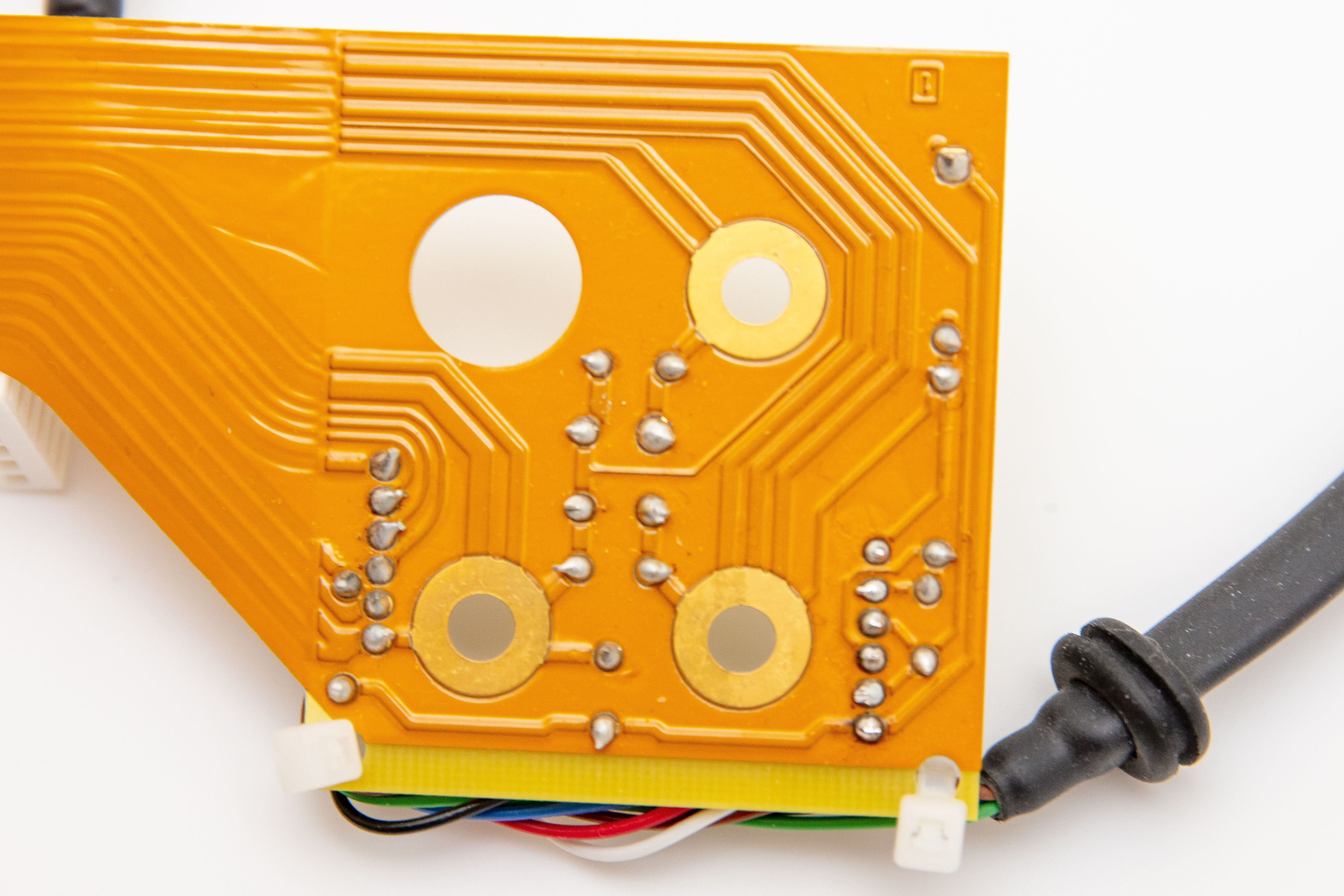
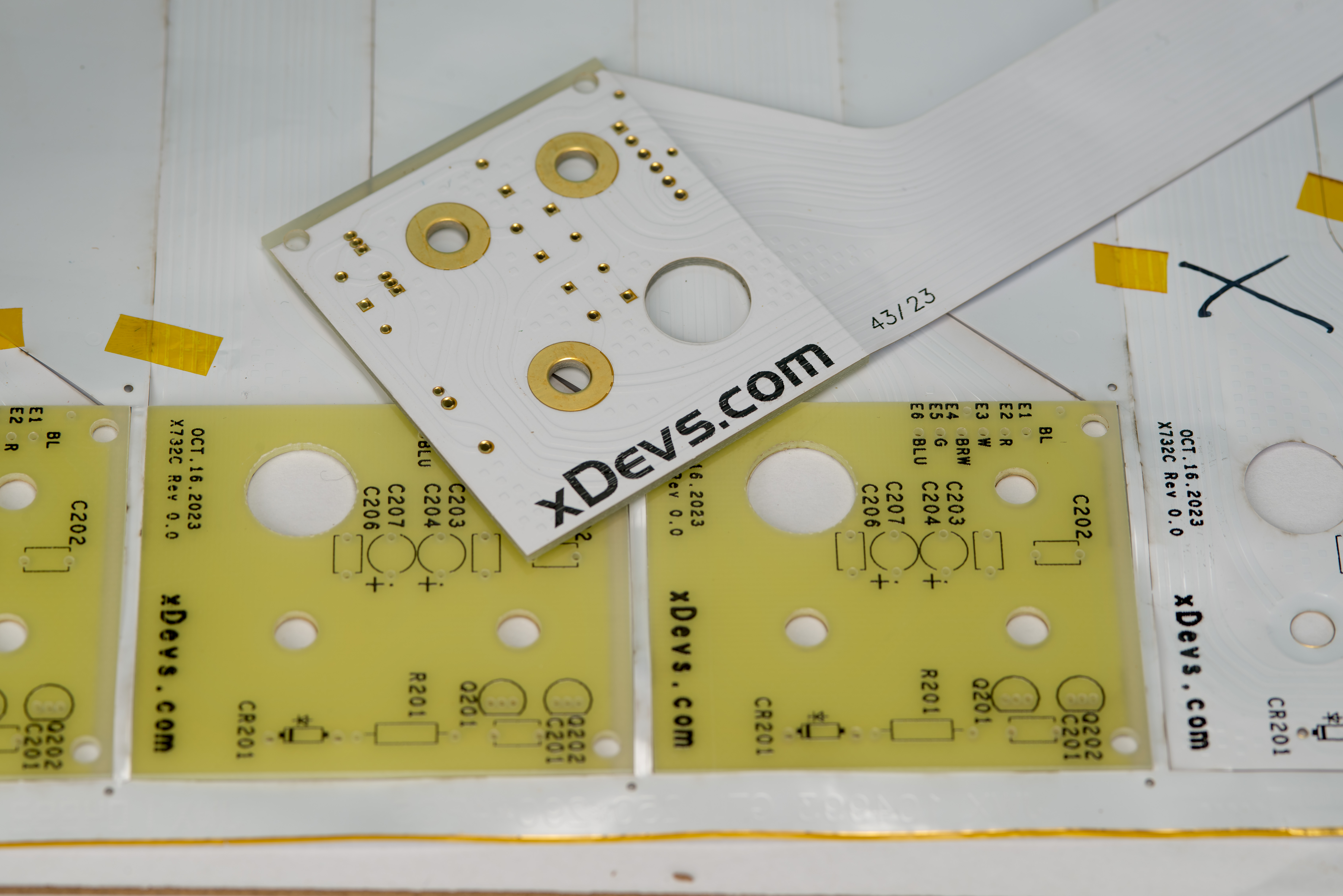
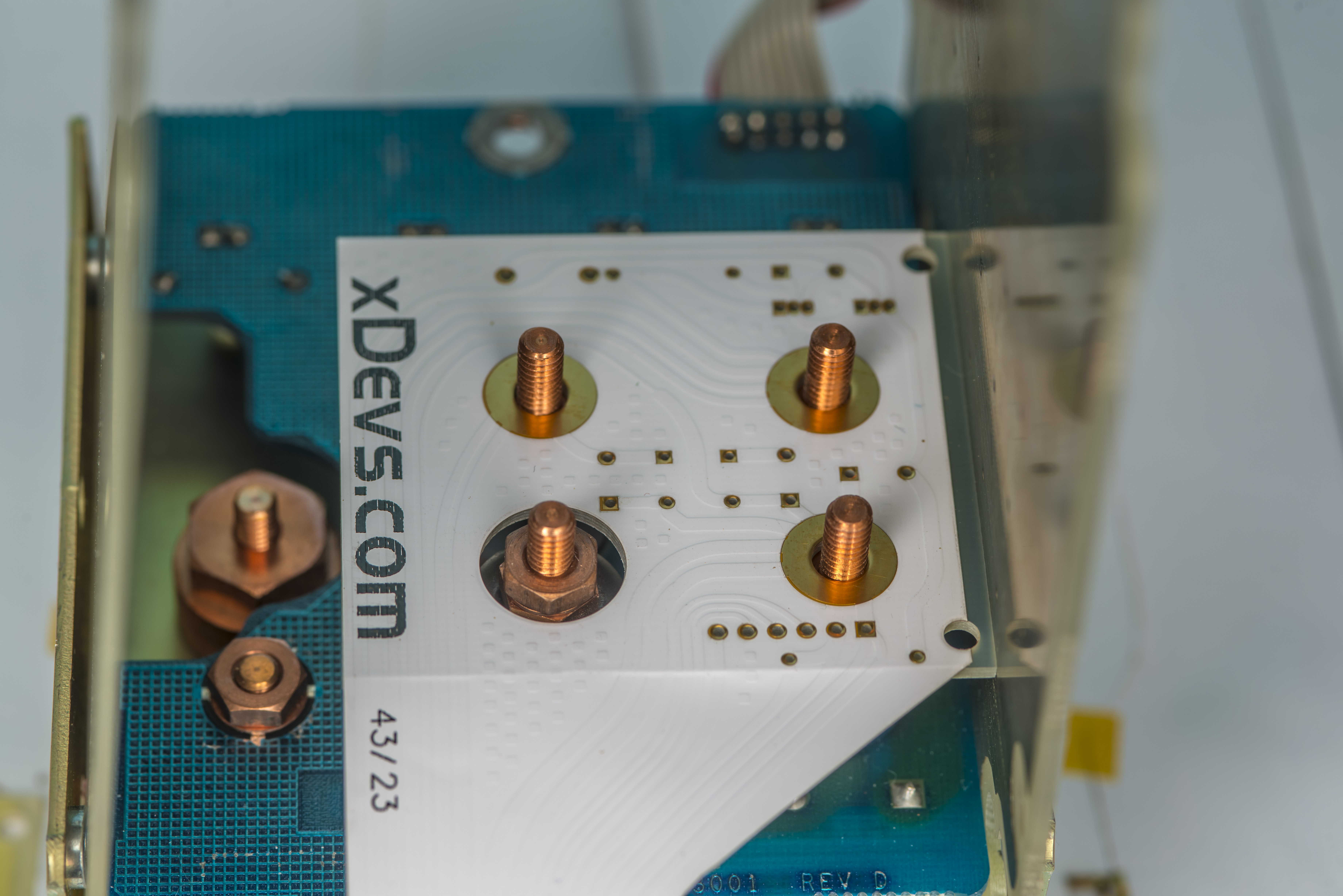
Zener core is connected to front panel copper low-thermal posts same way as with older 732B. Flex PCB with all signal routing is now simplified and bit smaller.
Unlike 732B, Fluke removed adjustable switches to trim the 10 V output on new 732C. So user cannot adjust the 10 V output voltage of the standard, for example to match JVS-referenced calibration to have exact short-term 10.000000 V output. Keep this in mind if you replacing 732B in your lab to new 732C.
732C manual still shows rendering picture with adjustment switch ports marking and locations, but it’s incorrect and all that was removed in actual 732C units.
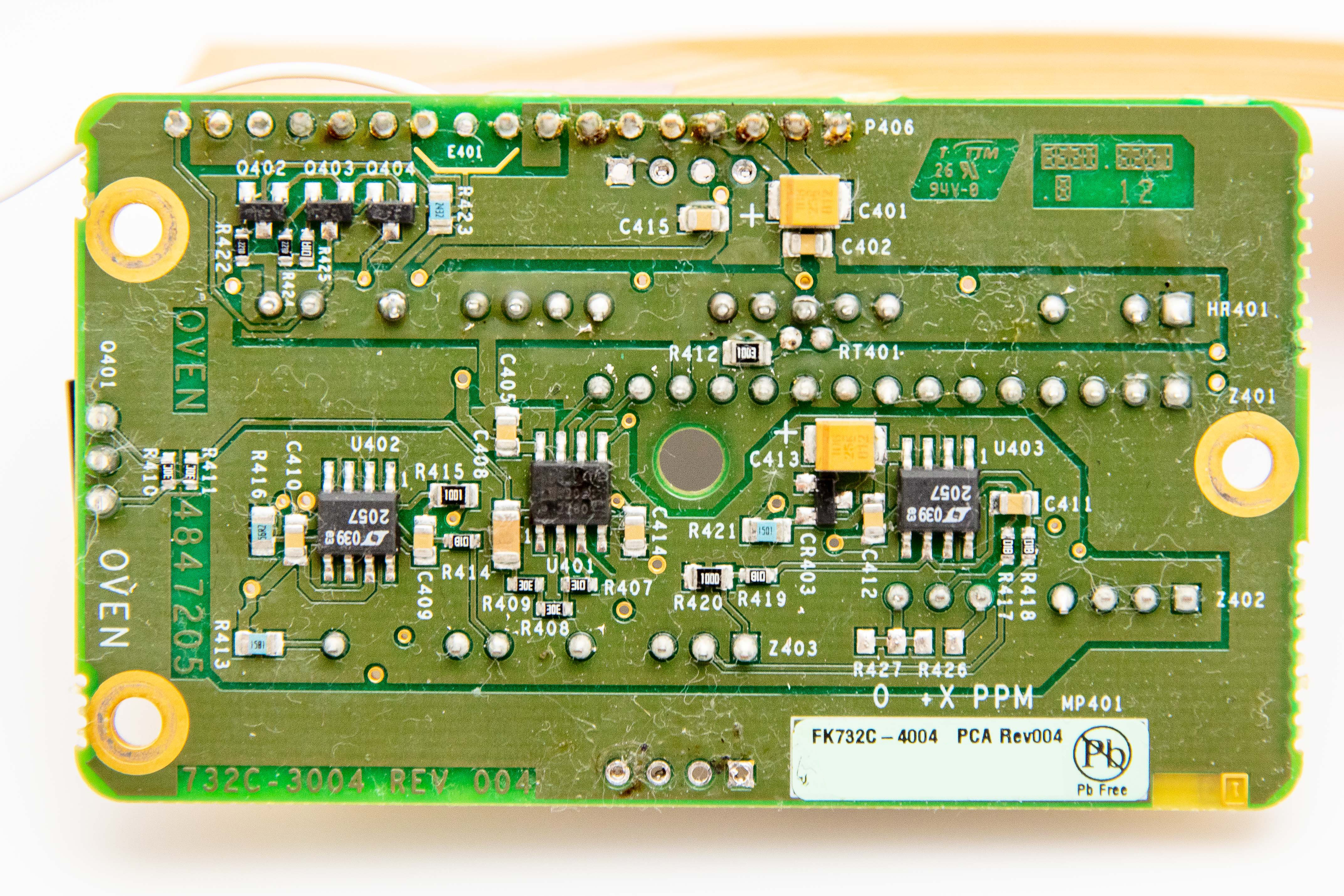
Now back to components photographs:
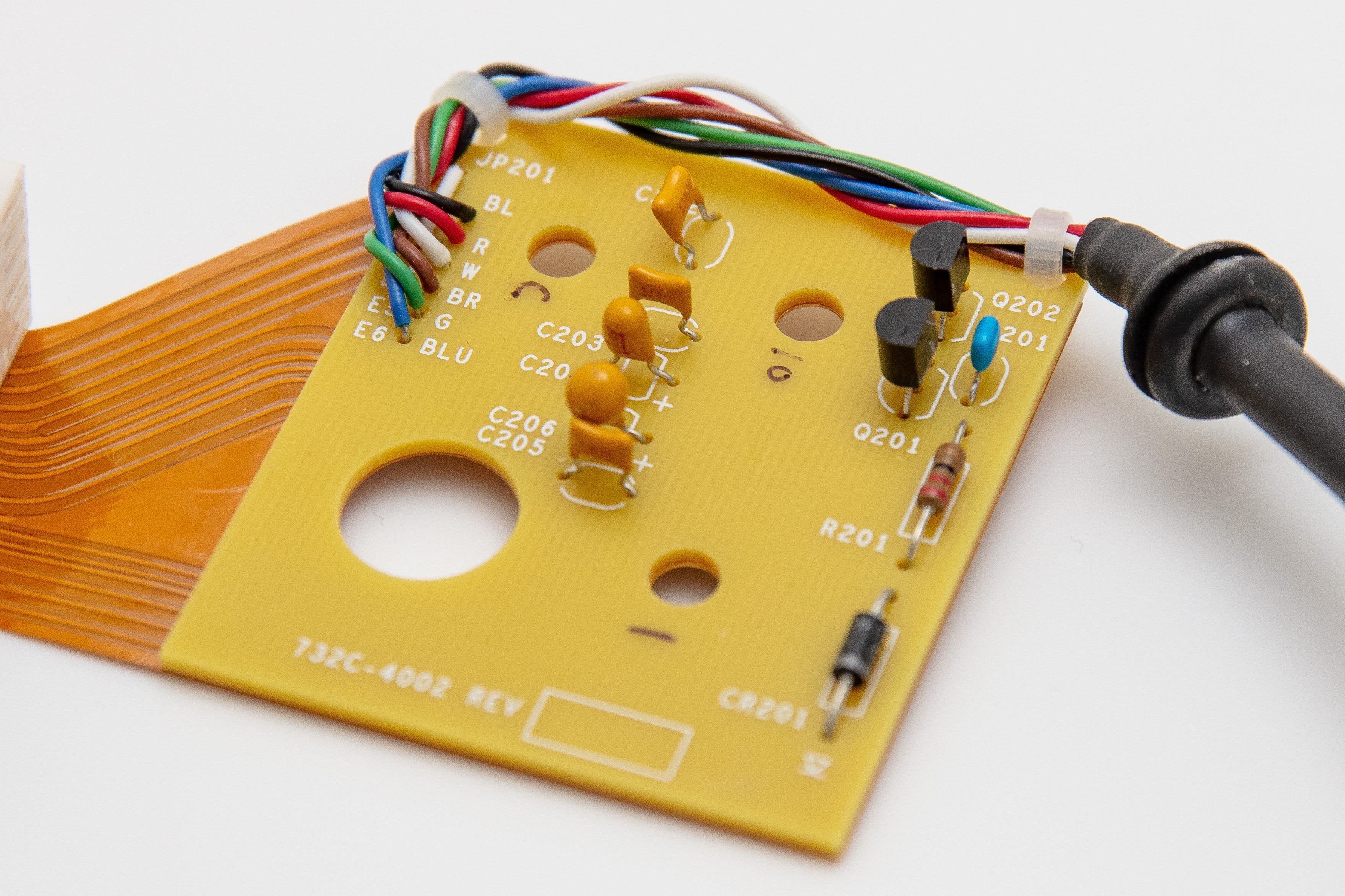
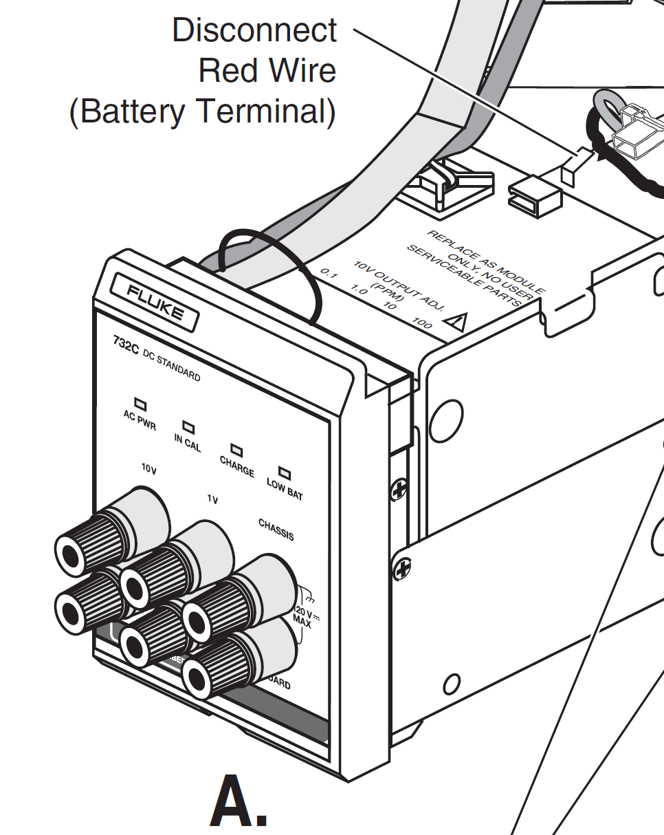
Capacitor combinations of MLCC and tantalum sit across output 10V and 1V voltage terminals to give some edge filtering.
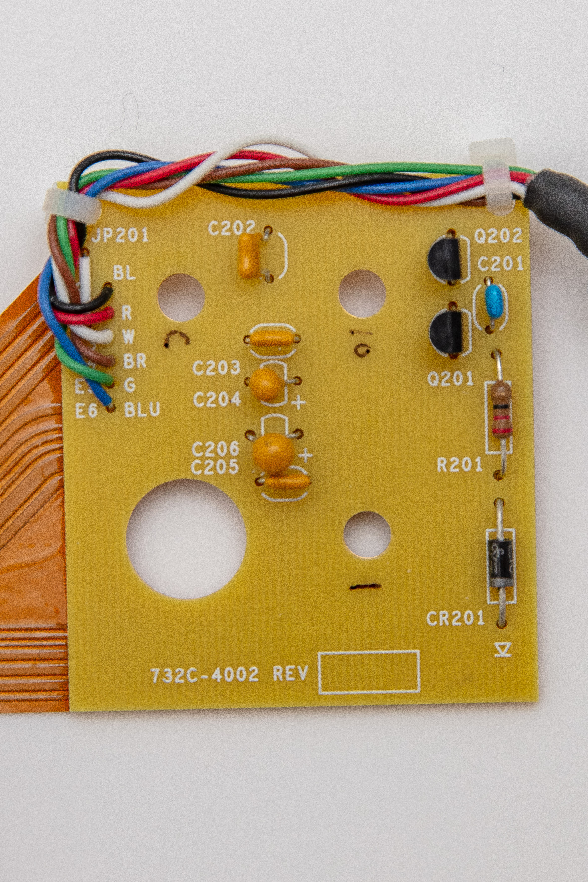
Q202 and Q201 provide drive current for the loads connected at the output.
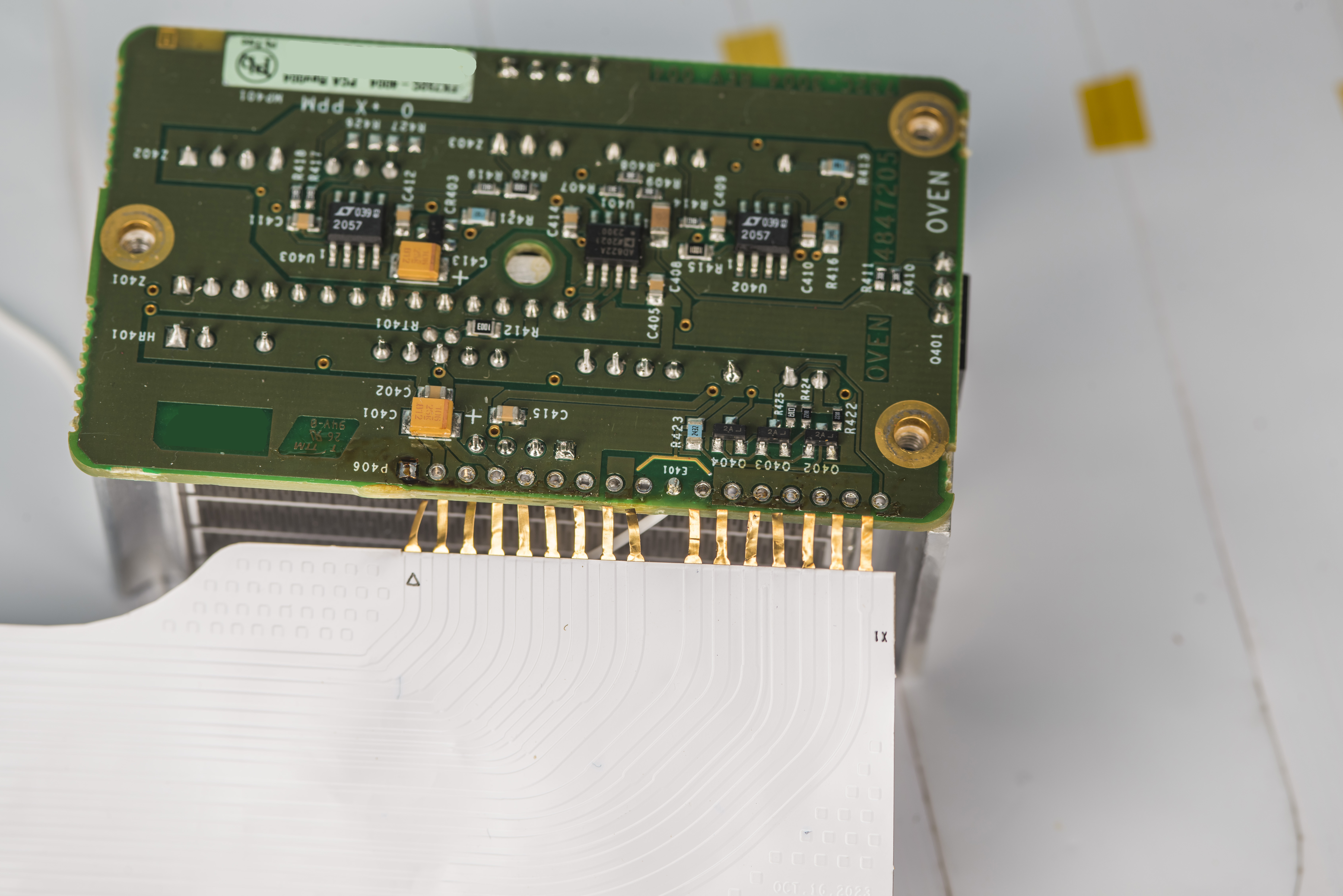
Oven block has own controller PCB with heater regulator, few opamps, some passives and interconnects for hybrids with ceramic substrate.
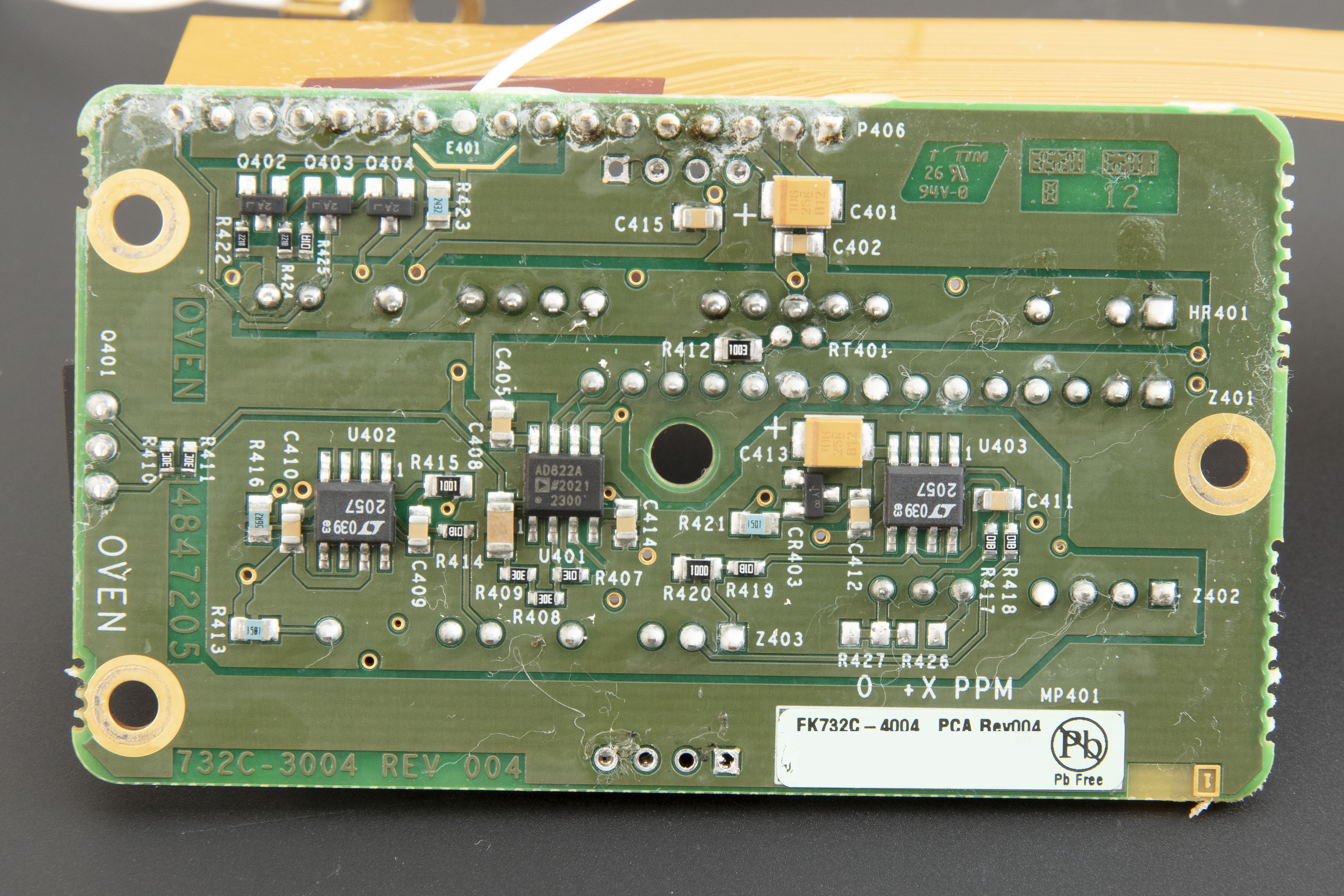
Here we can spot few active components, especially two chopper amplifiers LTC2057 and low-bias current AD822A dual opamp.
Pair of 200 Ω heaters on the side are same as older model reference. They are epoxied to massive aluminum box to get slower thermal response and more uniform oven operation. Heaters attached with hard thermal epoxy.
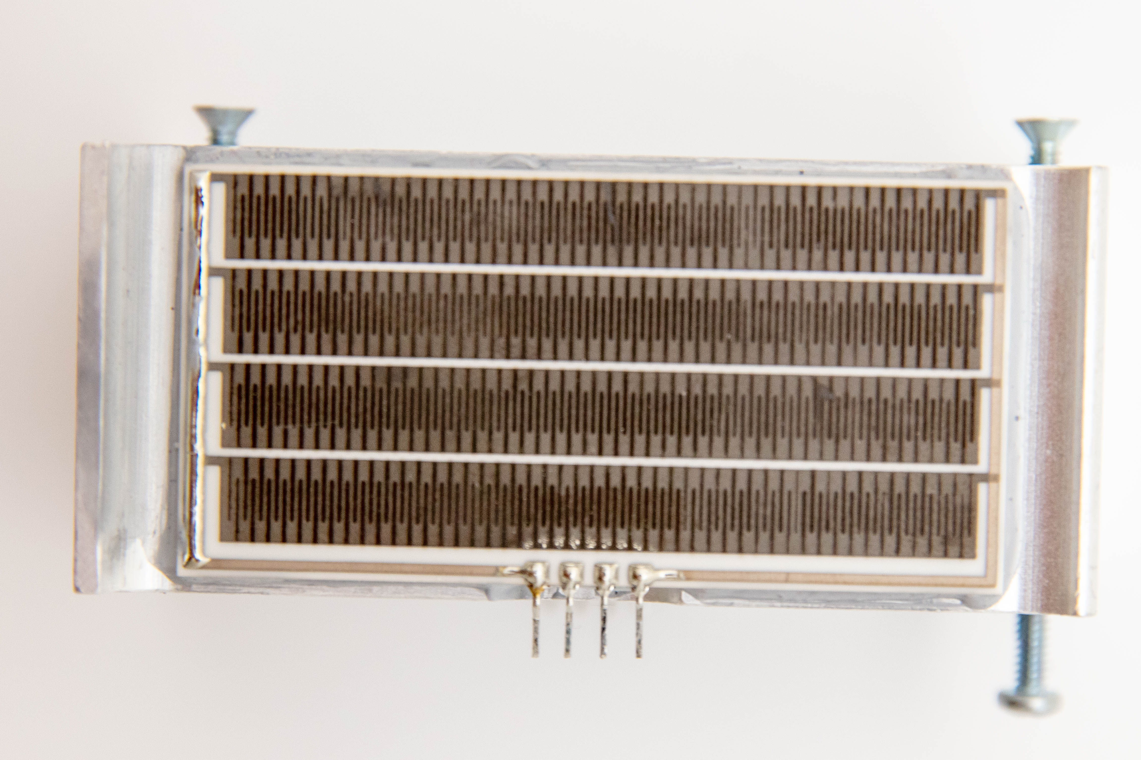
Power transistor is mounted on the short side of the aluminum frame.
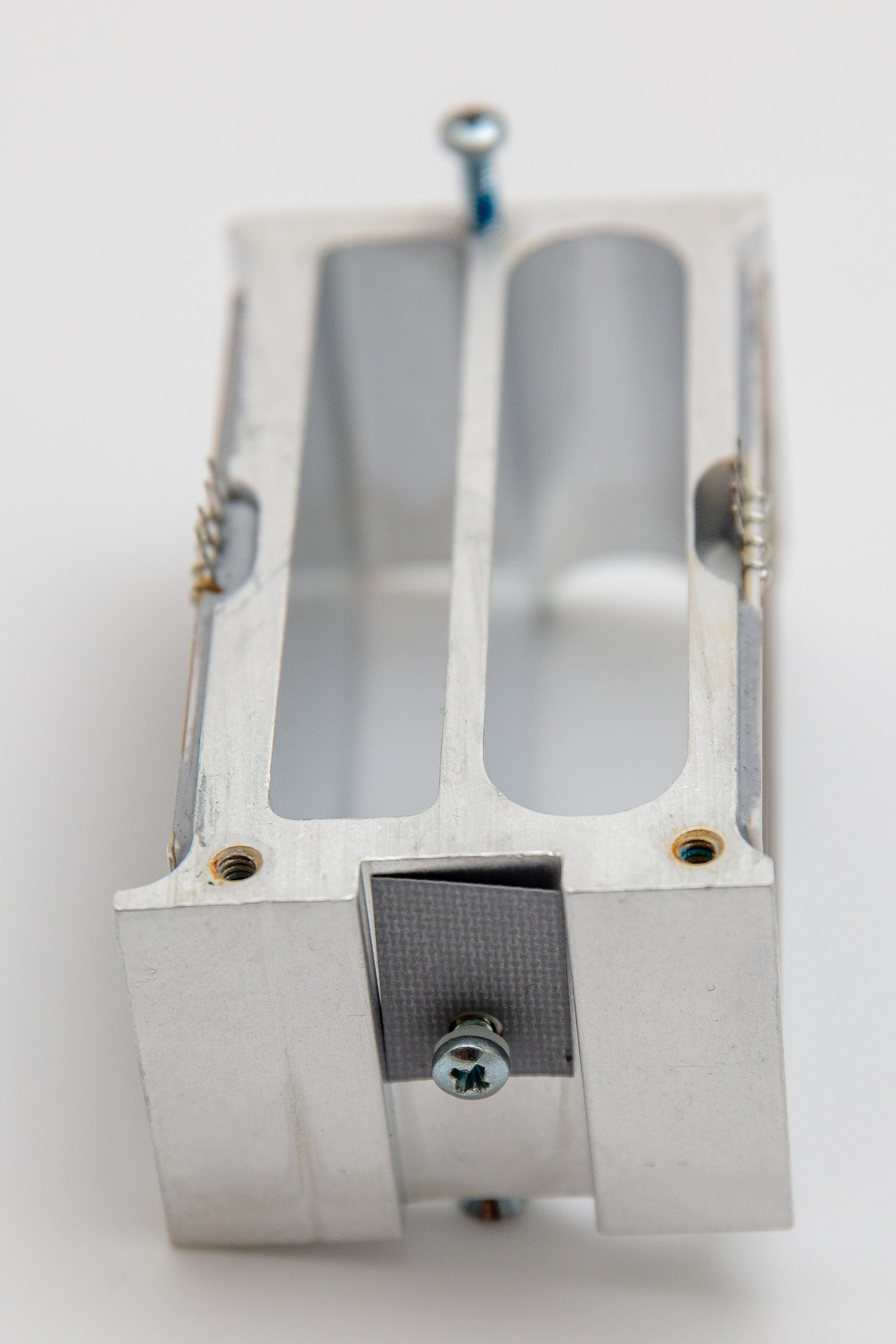
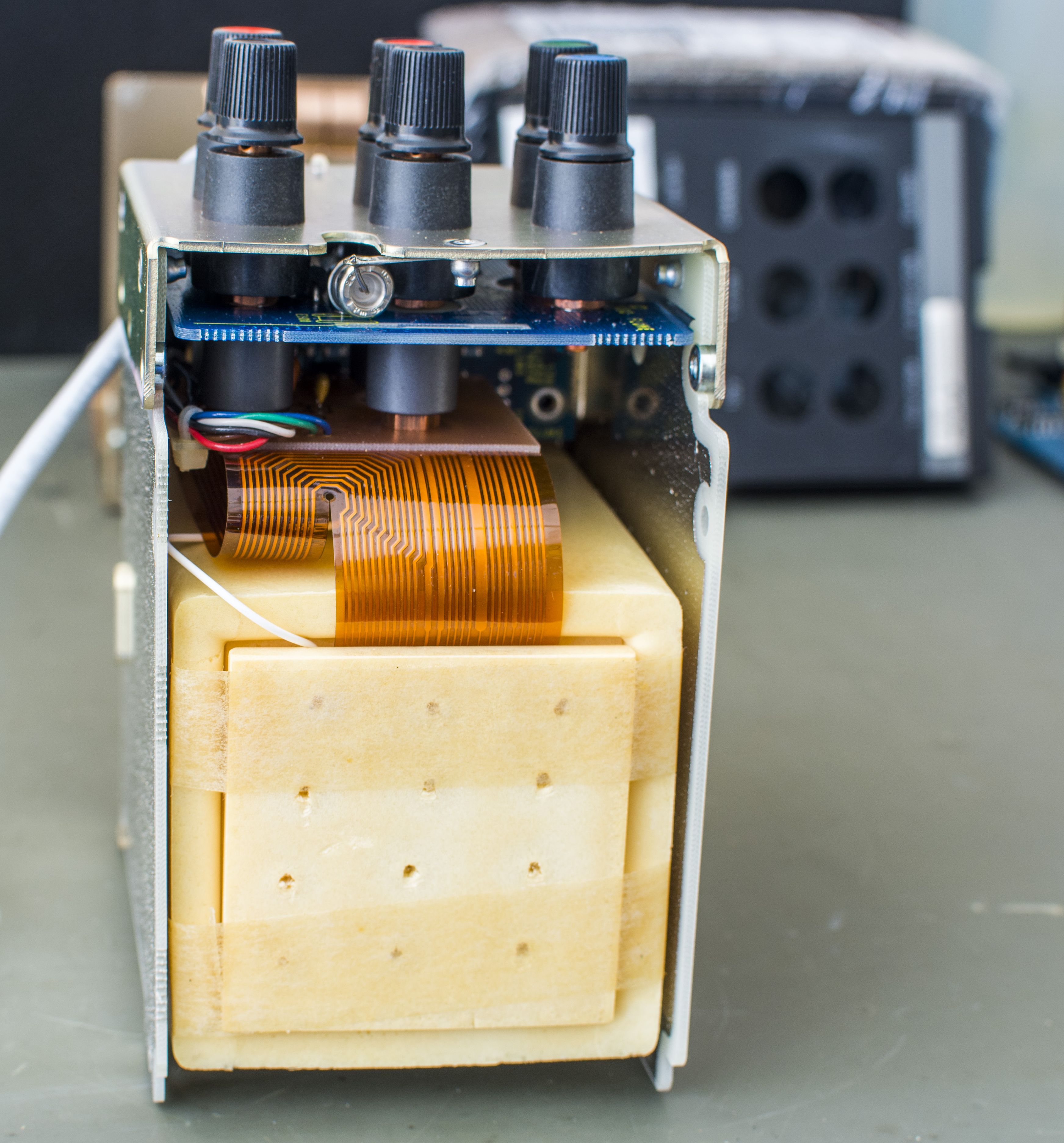
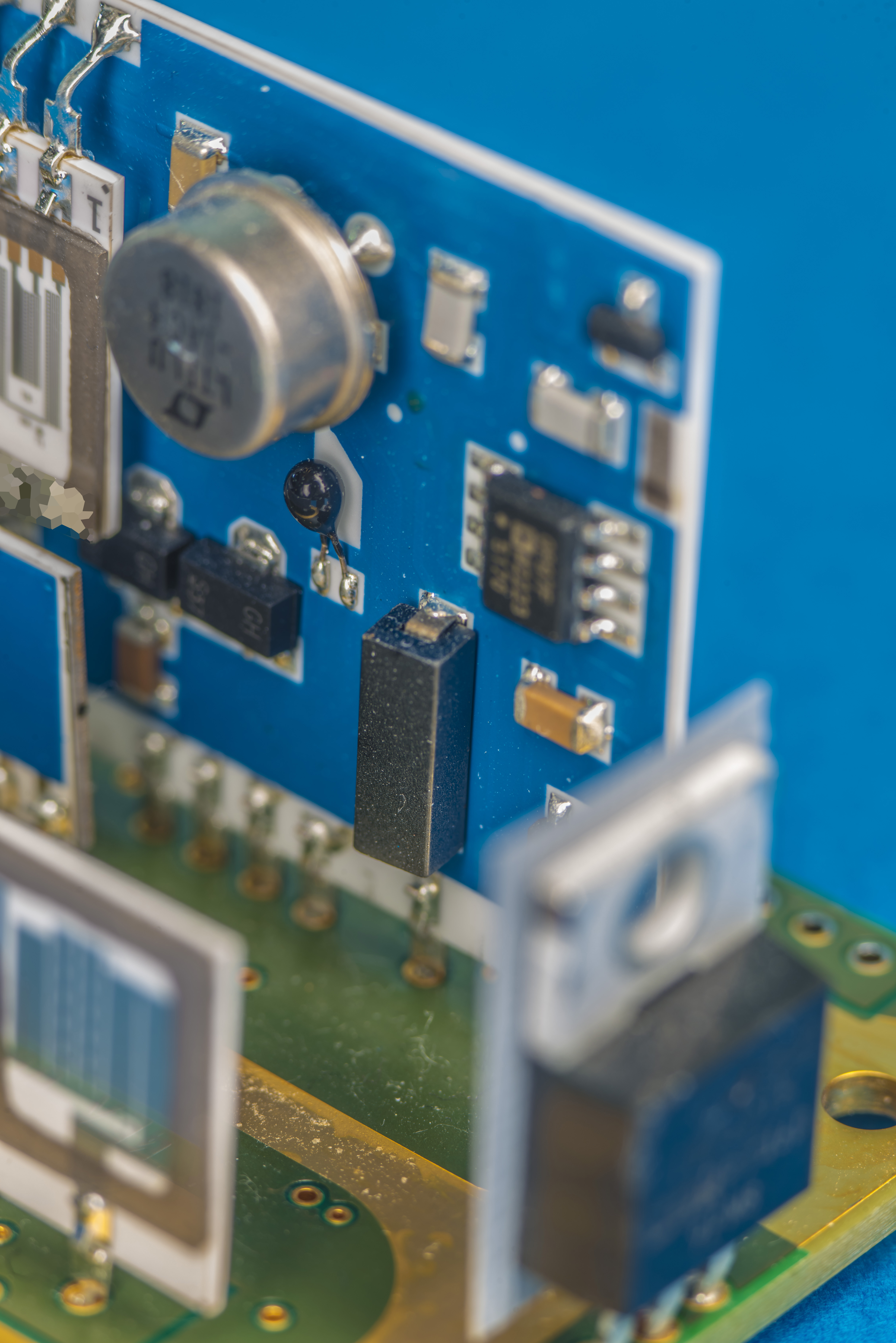
And star of the show, actual zener reference with all precision hermetically sealed thin-film NiCr resistance networks:
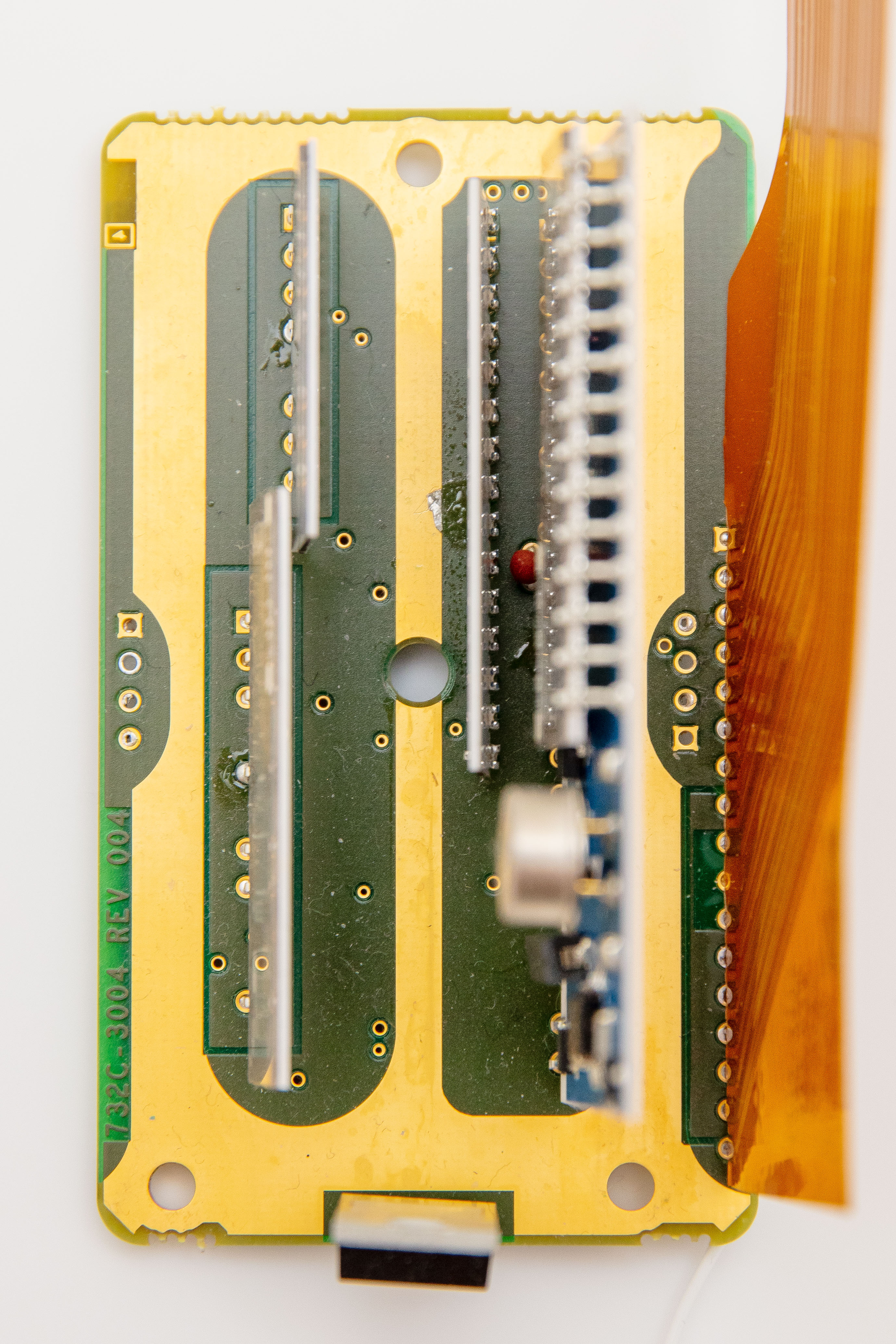
Precision wirewounds in round hermetically sealed brass enclosures are now gone and replaced by cheaper laser-trimmed thin-film NiCr networks.
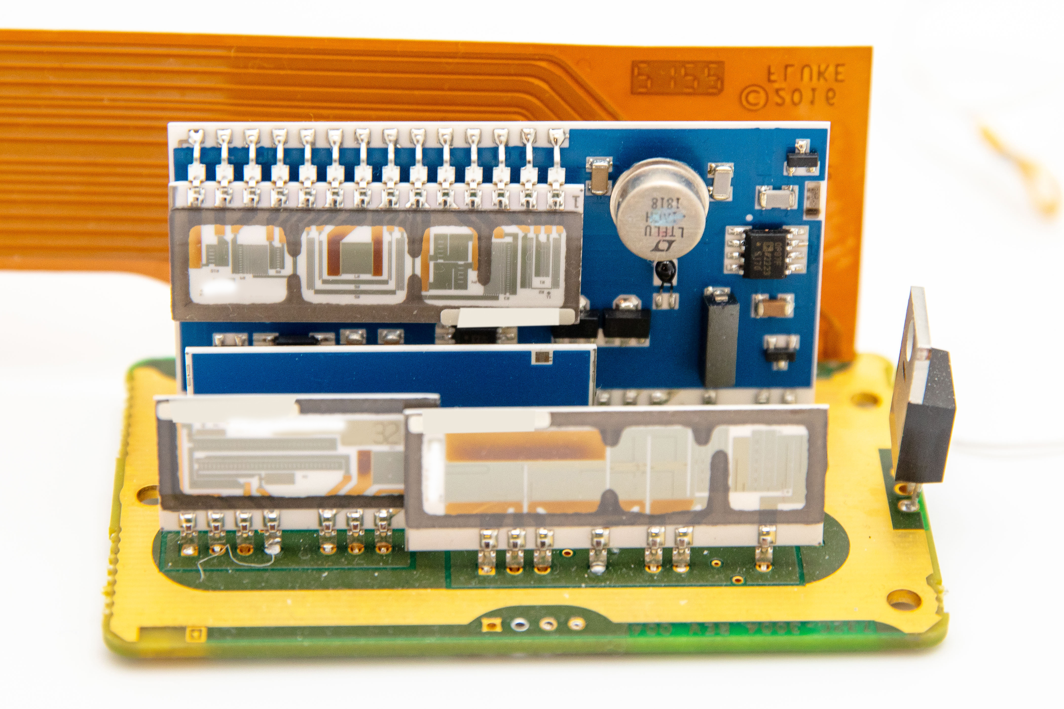
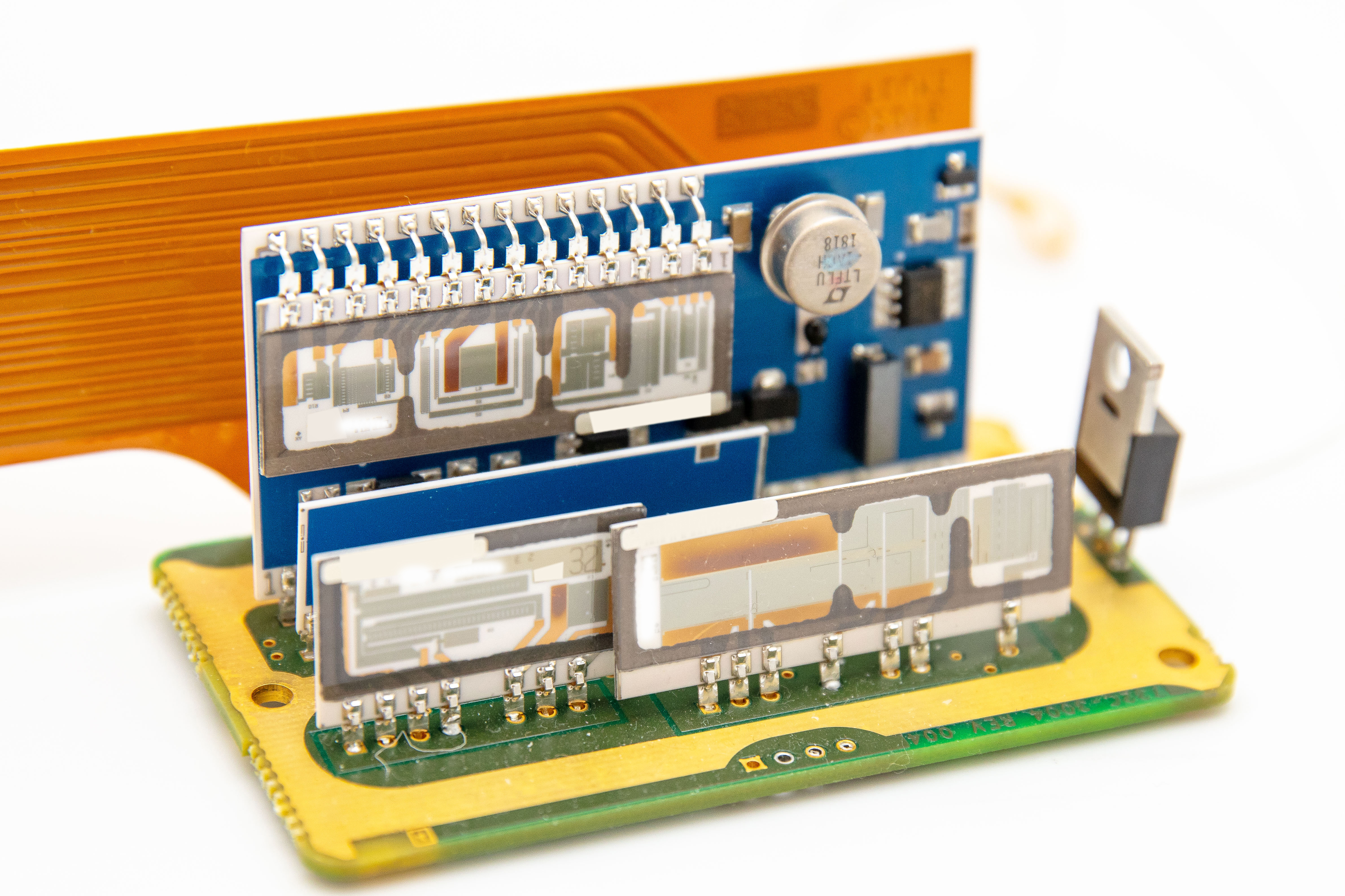
LTFLU-1ACH Ref-Amp in this particular 732C was manufactured around week 18, year 2018. There is OP97F nearby, thermistor bead and same thin-film network as on 732B. Higher resolution photographs are also presented below.
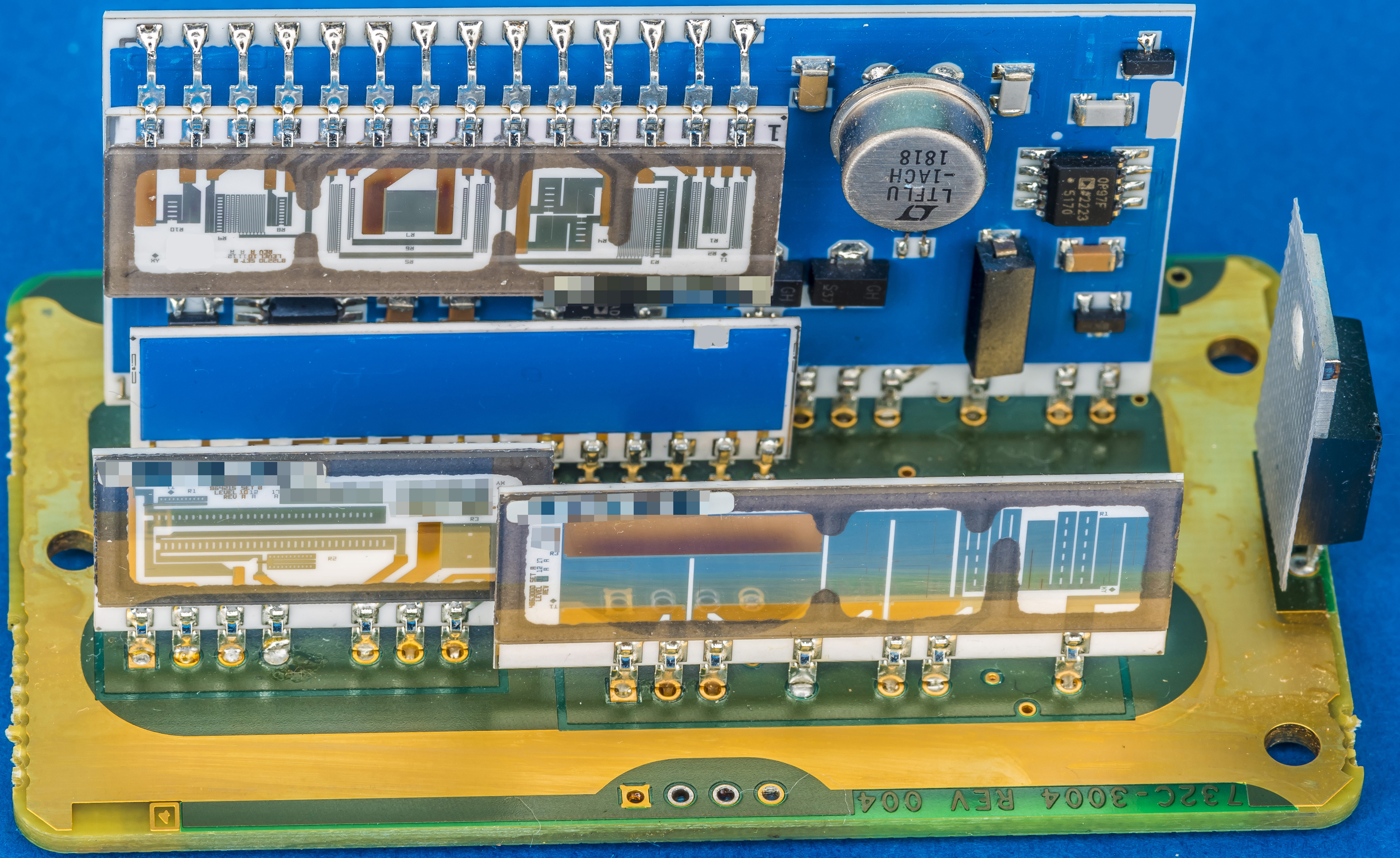
With higher resolution we can enjoy the beautiful laser trimmed thin film networks, responsible for the good stability of the instrument. All photographs are clickable for maximum resolution.
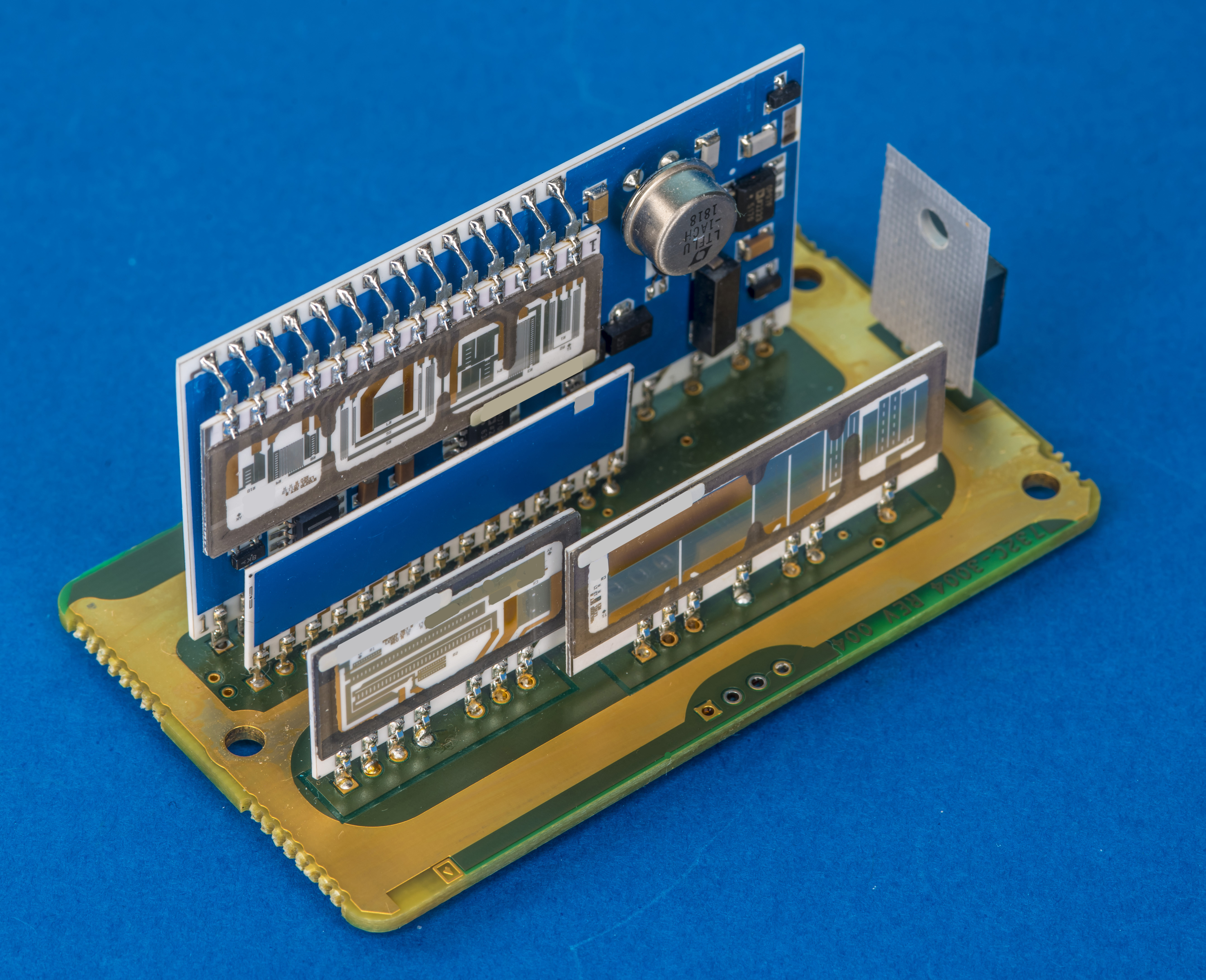
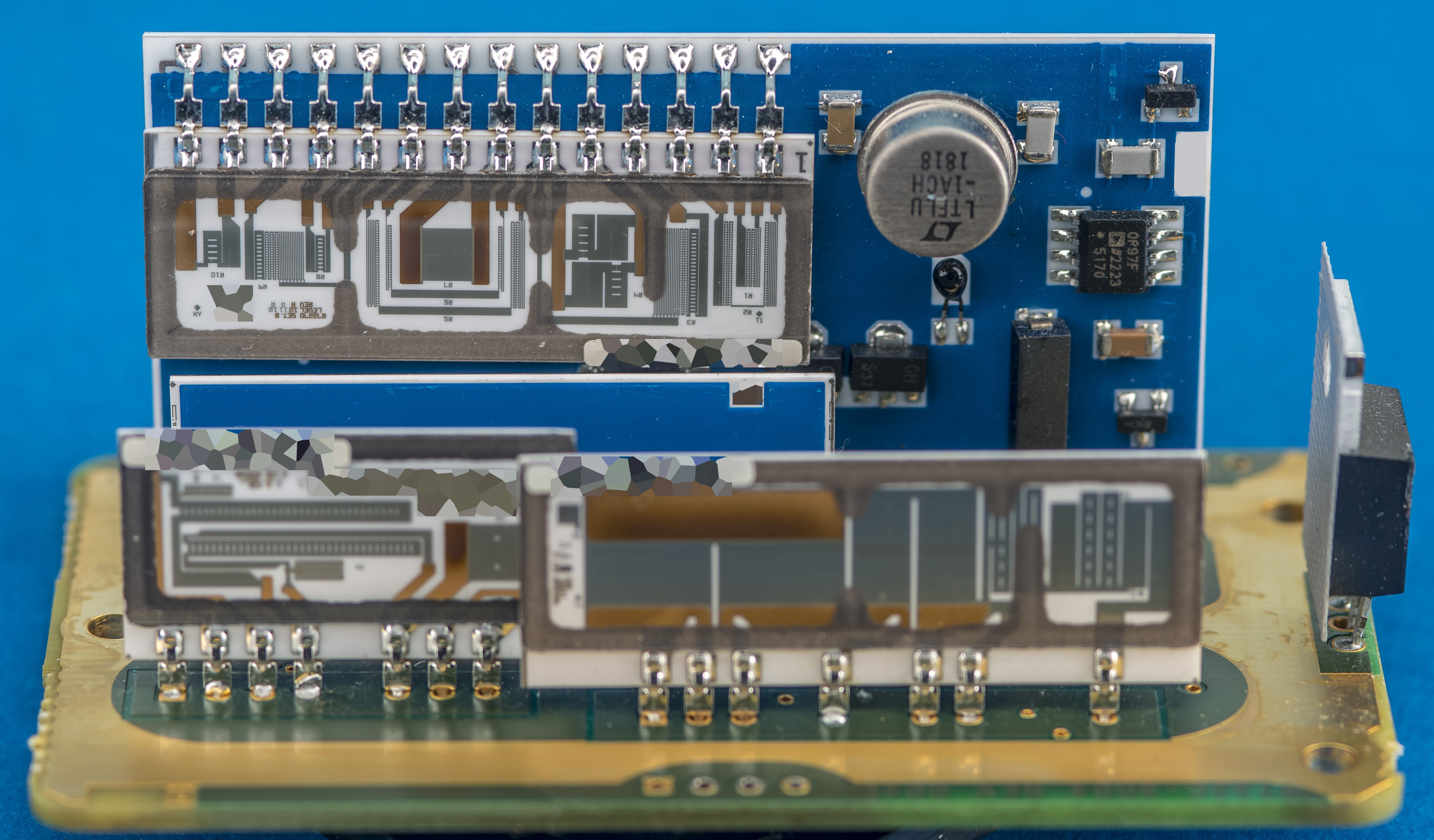
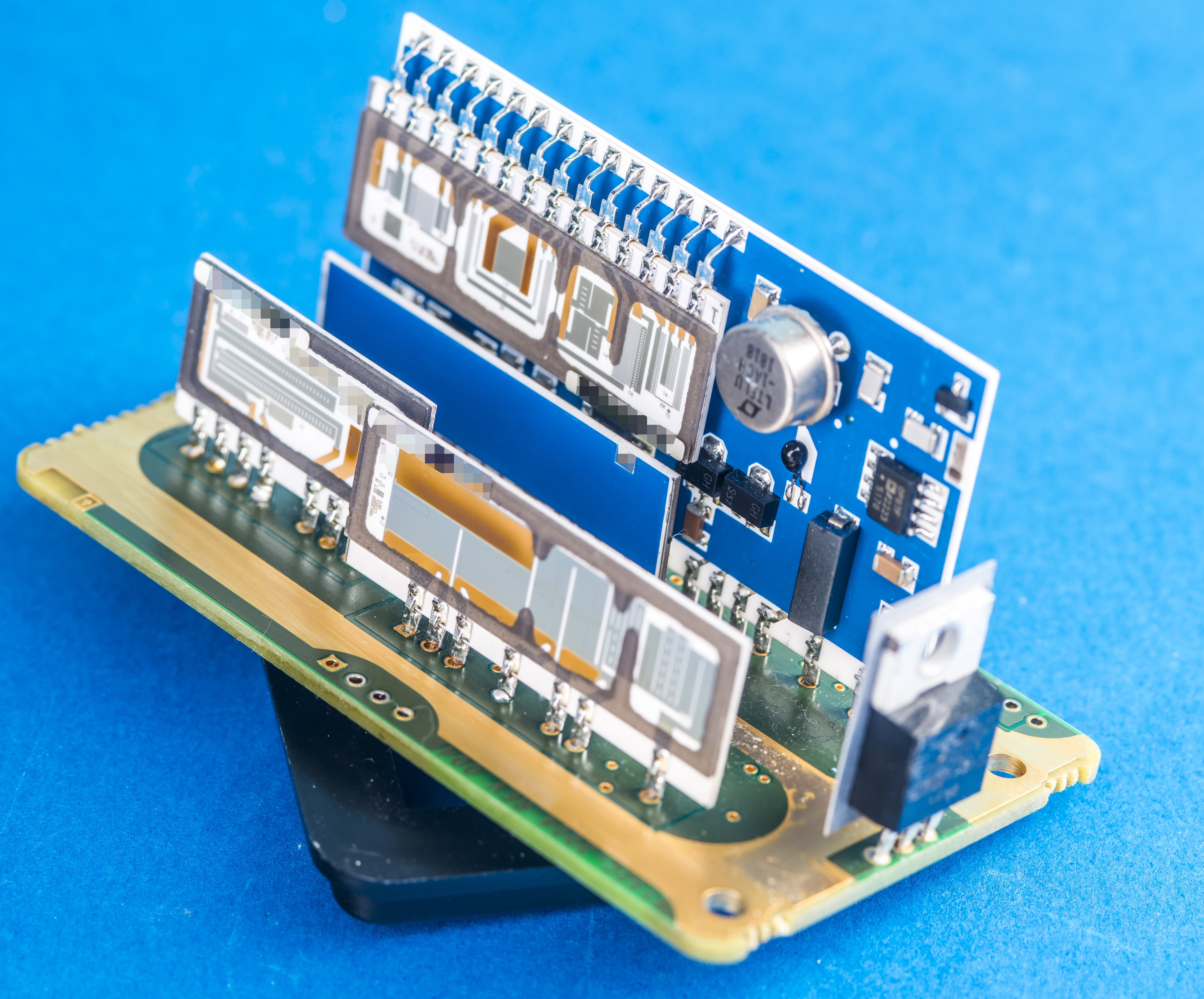
Previous 732B model used precision wirewound for 1.018 V output, but here they were replaced with two thin-film networks with addition of 0.1V output.
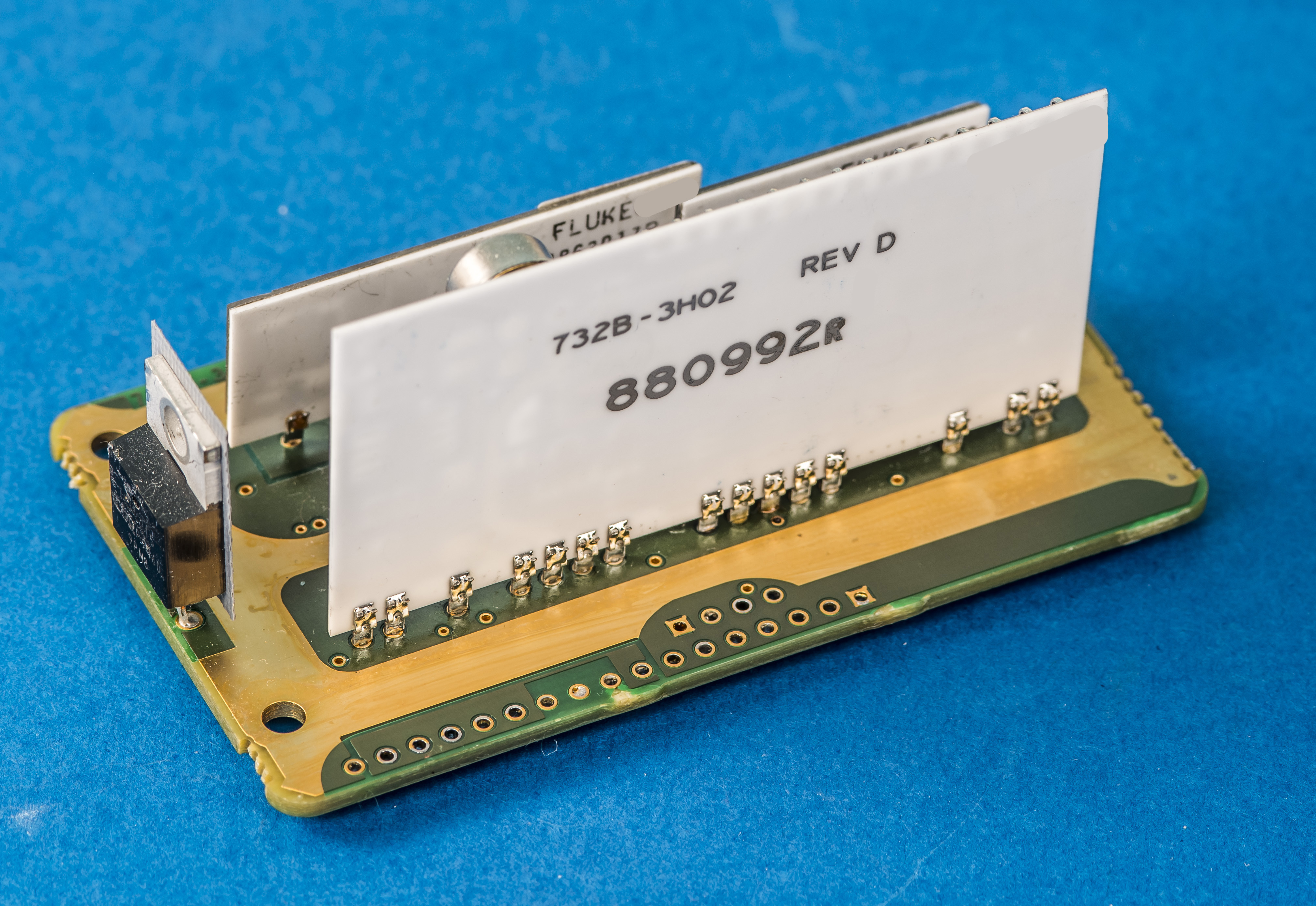
As label on REFAMP core hybrid hints it is unchanged from 732B and marked with 732B-3H02 Rev.D part number. Internal Fluke P/N is 880992R.
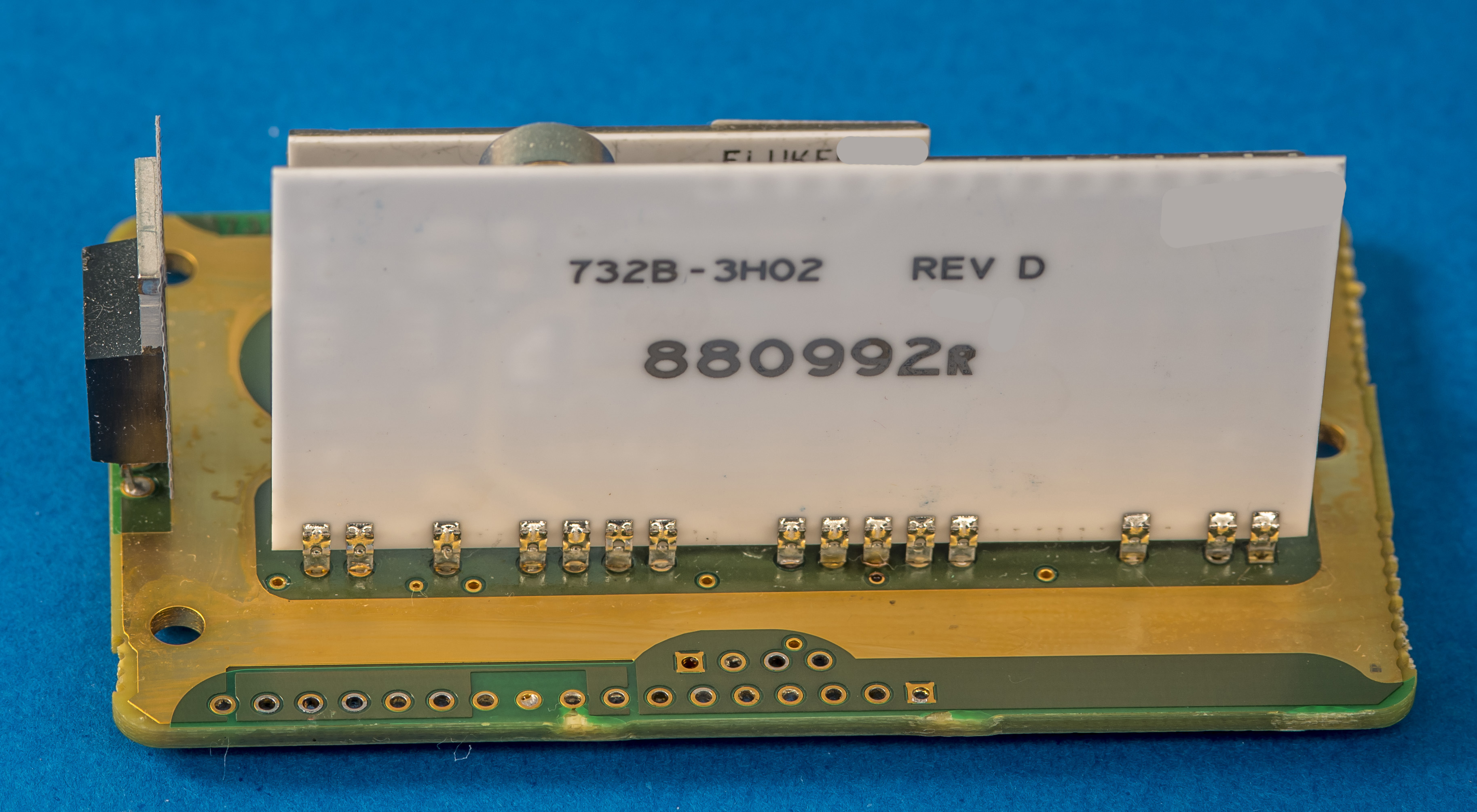
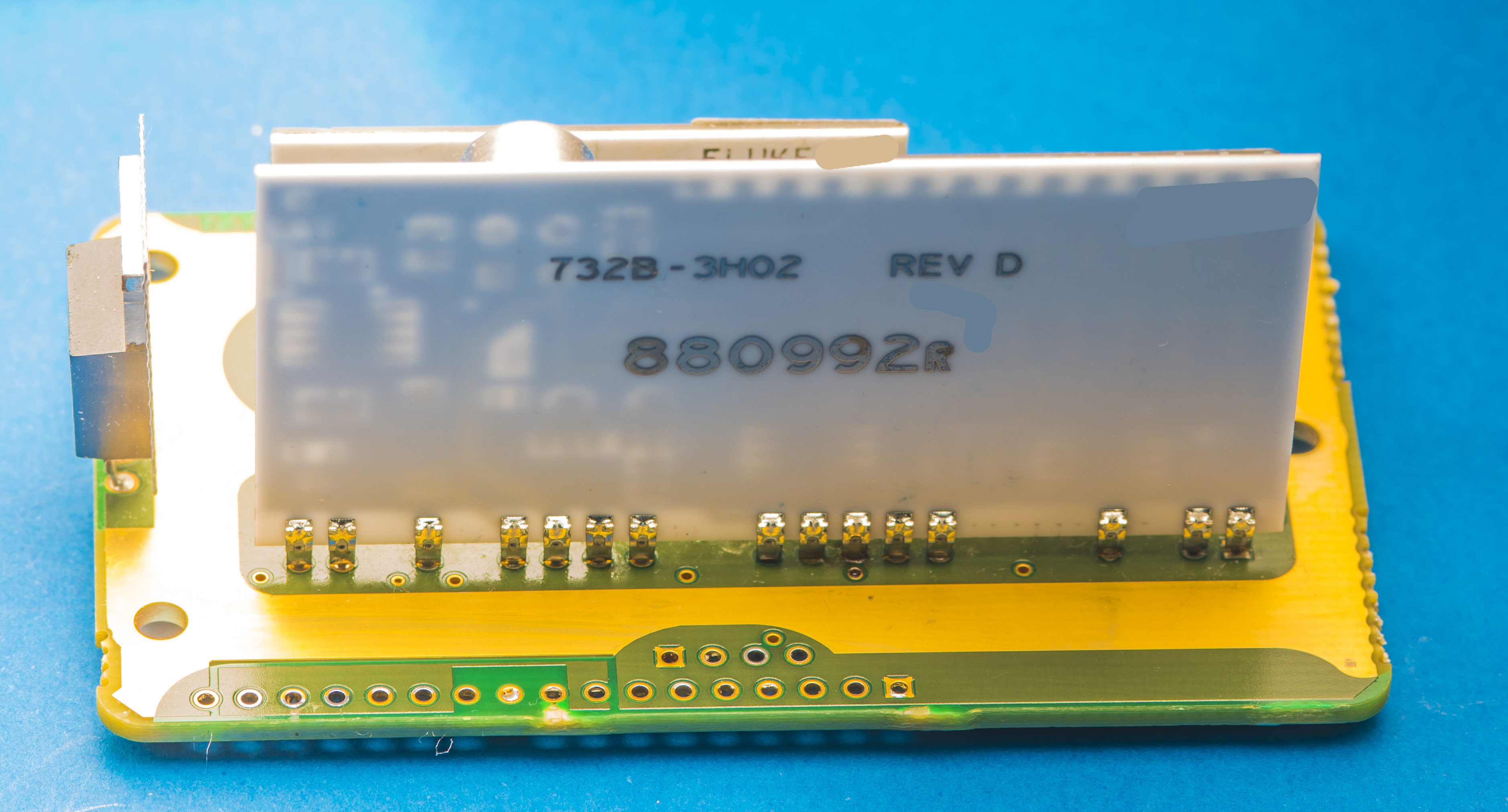
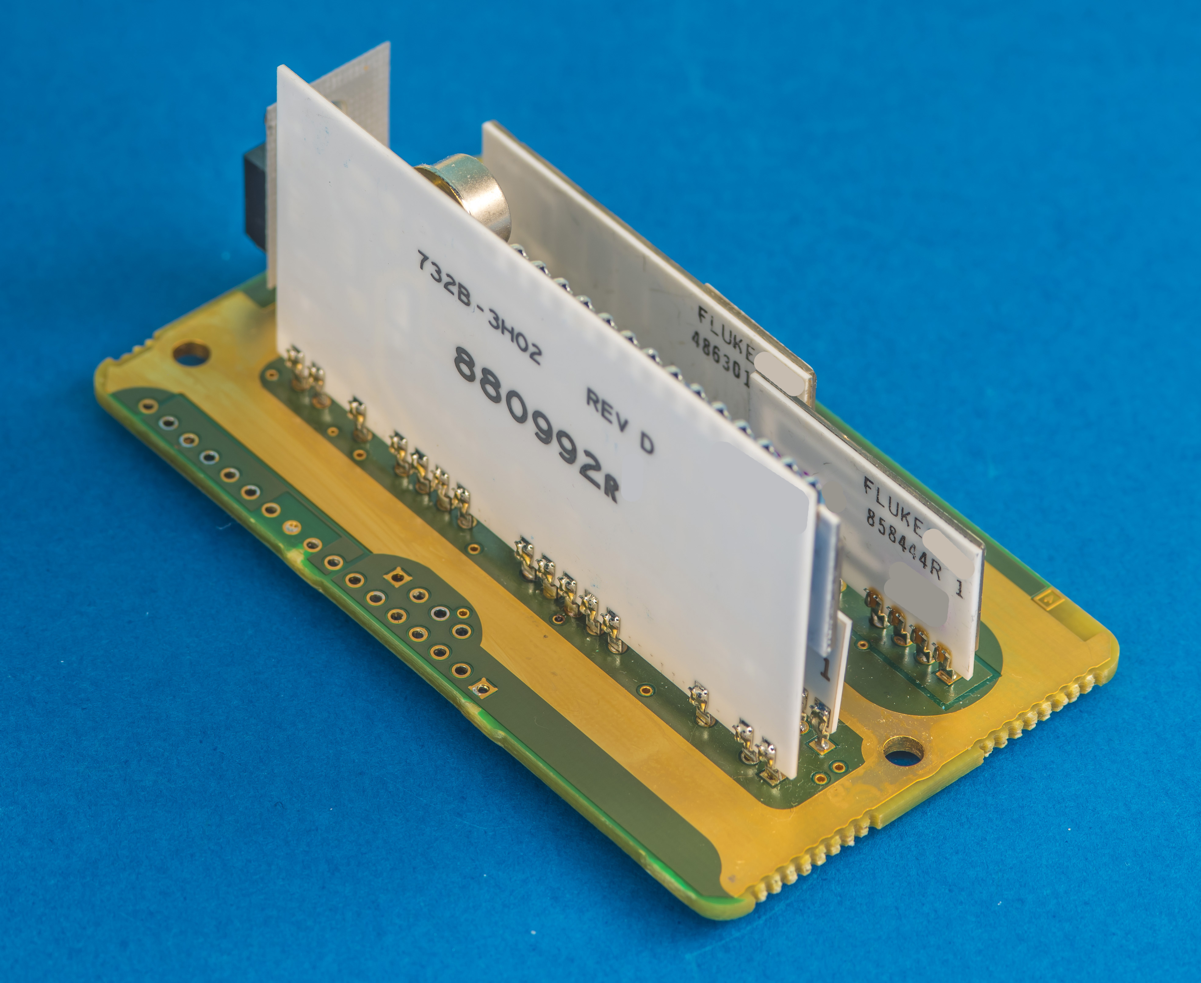
All metal traces and passive film resistors are embedded on the component surface and protected by thick blue masking paint/compound.
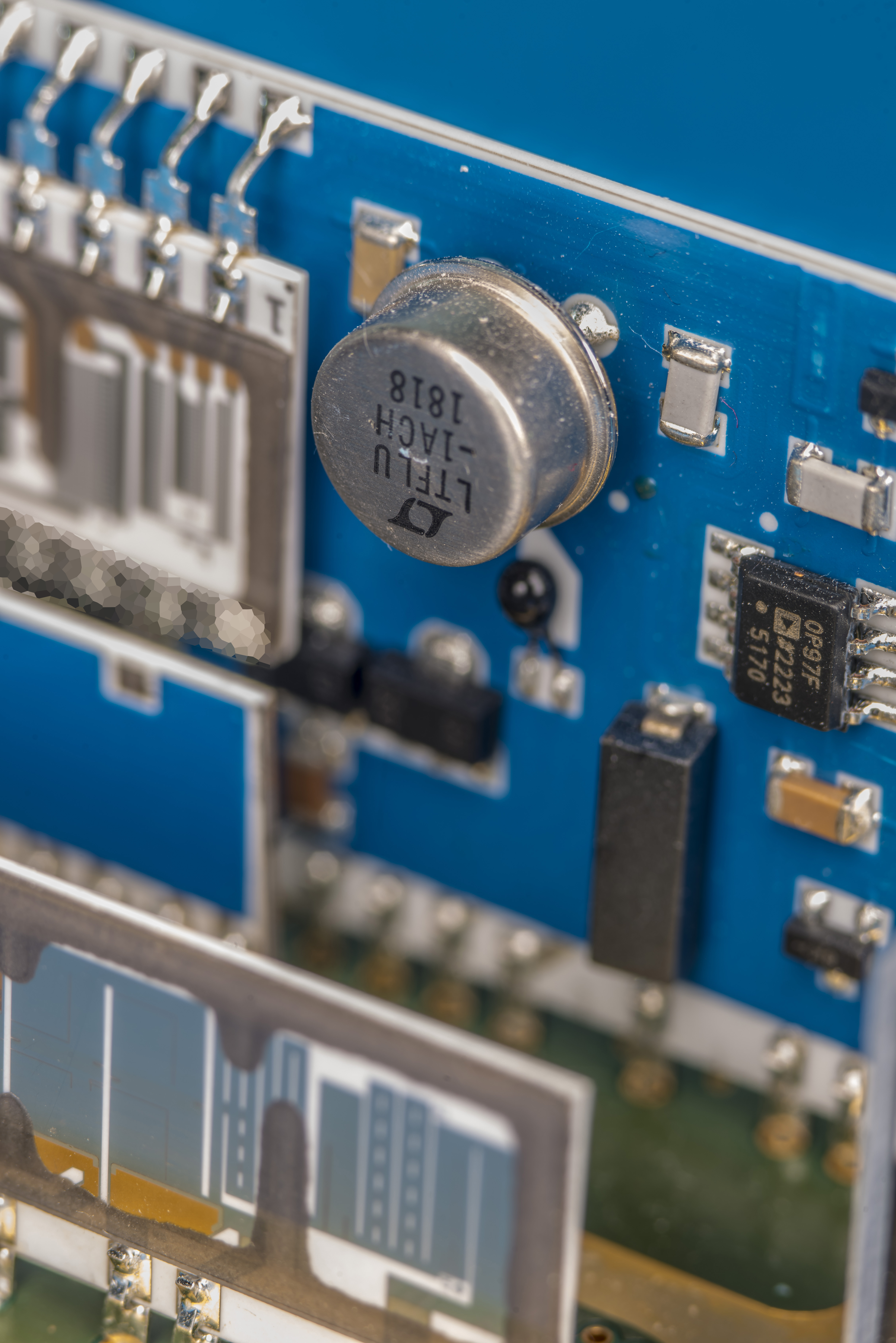
Bead 100 kΩ thermistor is placed right next to LTFLU chip. It is one used for temperature control of the oven assembly.
Resistor network P/N 872270 on REFAMP core hybrid is also same as Model 732B standard.
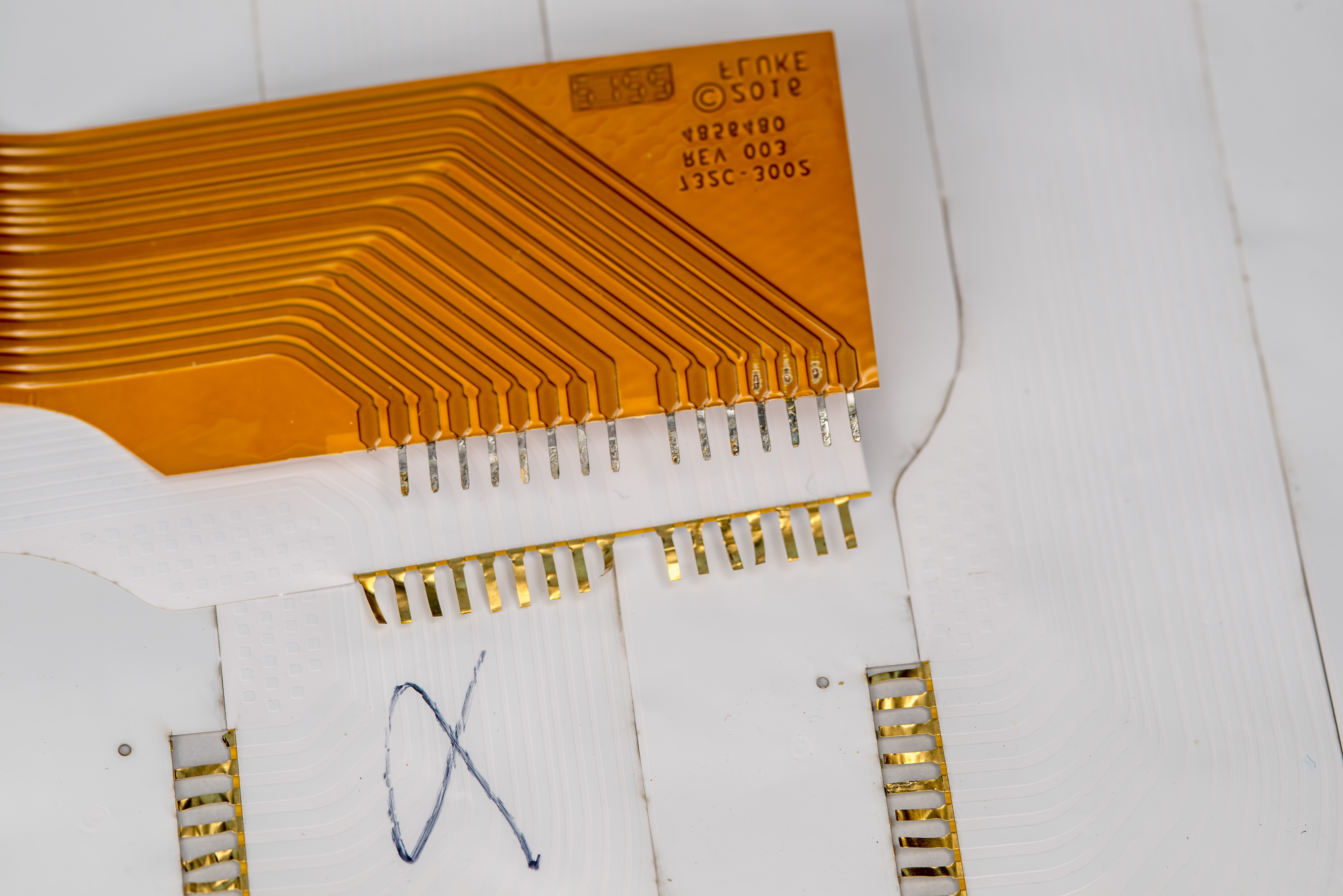
Repairs of 732C with a new flex circuit design
This unit required flex PCB replacement. I’ve had it rebuilt per internal xDevs design to provide correct operation. So here we can see the 732C core with replacement flex PCB.
Single white wire dangling off the PCBA is used to route 100mV output to the front panel binding post. Perhaps wire is designed this way to reduce leakage on this sensitive node from the flex circuit board.
In 732C 100mV is generated from passive resistive divider so it cannot accept any load if best uncertainty is required.
These flex PCB were pretty reasonably priced and did not use any advanced technology. As result experimental free air copper pins got quite mangled up and required some careful unbending to get into position on the PCB.
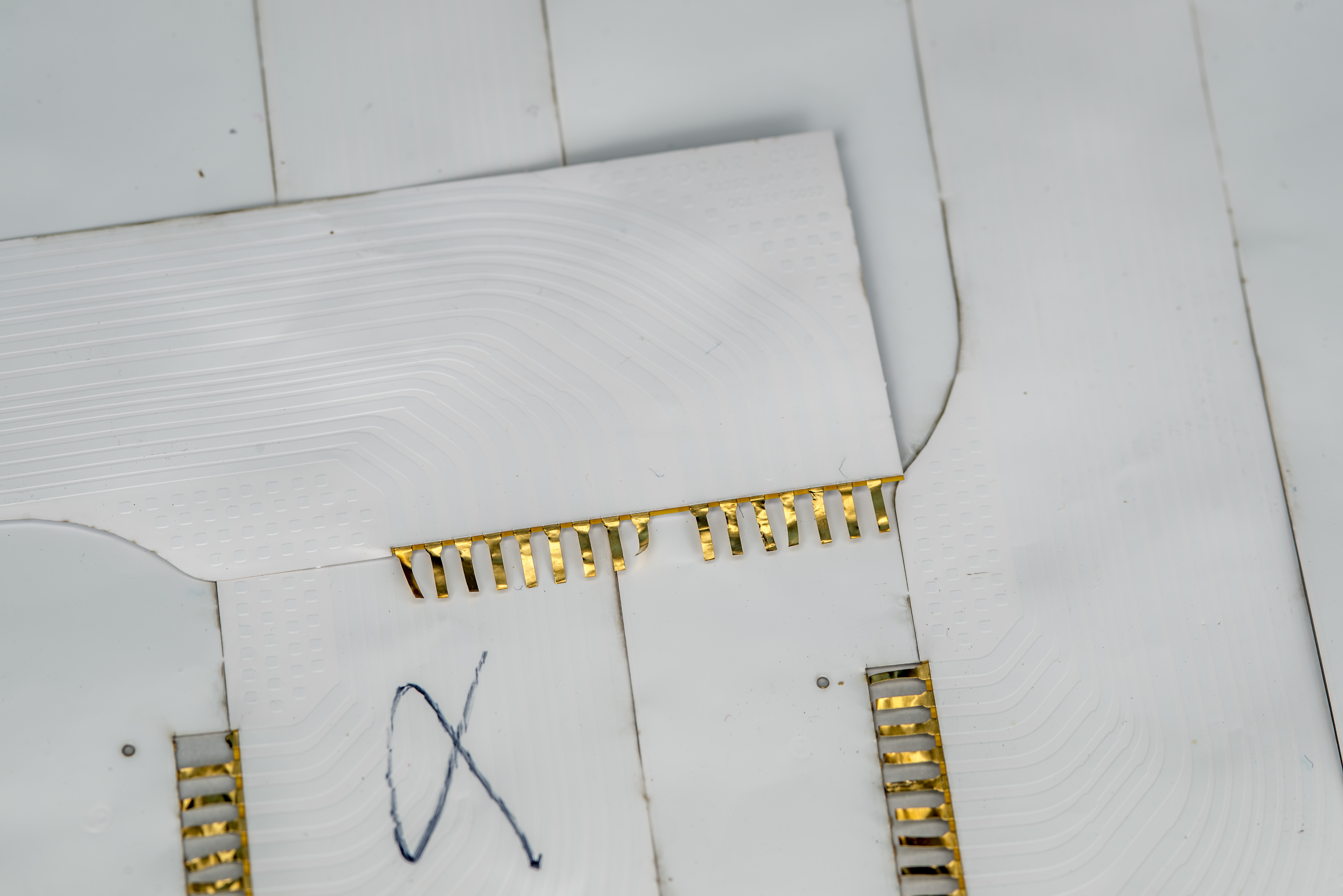
Compared to original Fluke flex PCB which used much more thicker copper layer it is significant difference.
After moving components to the stiffener section that mounts to binding posts whole instrument was reassembled for tests.
Everything aligned well and provided no troubles after oven core was installed into box.
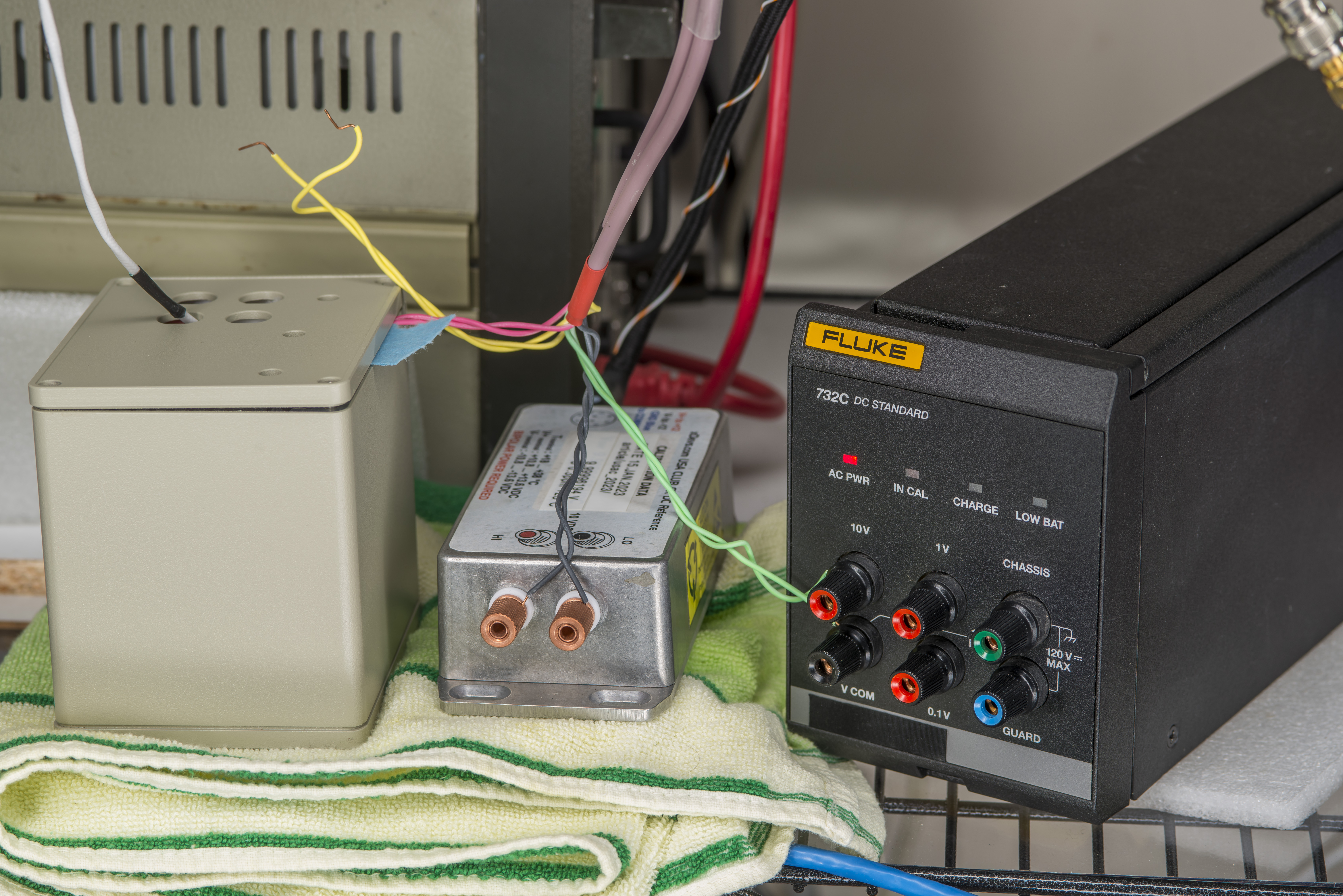
And finally Fluke 732C in natural habitat with zener array scanner system, together with ADR-based custom reference module and USA Cal Club FX LTZ1000A-based reference.
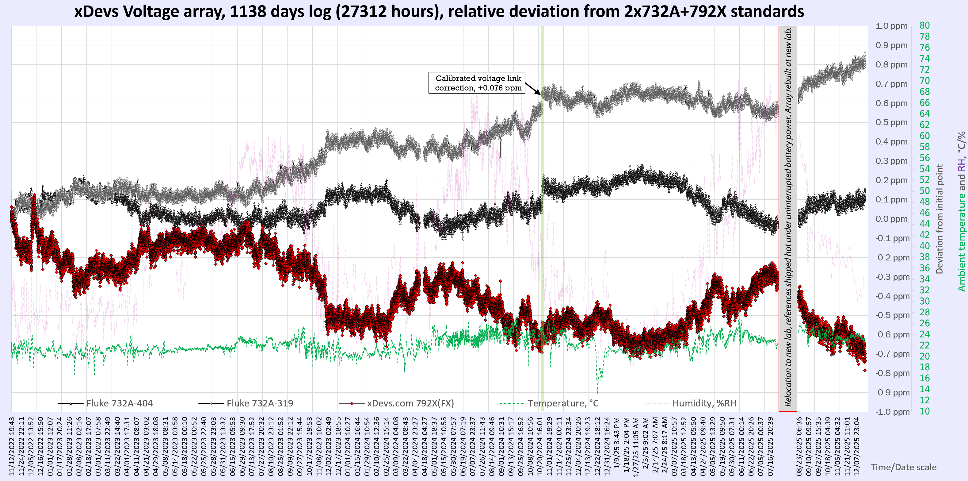
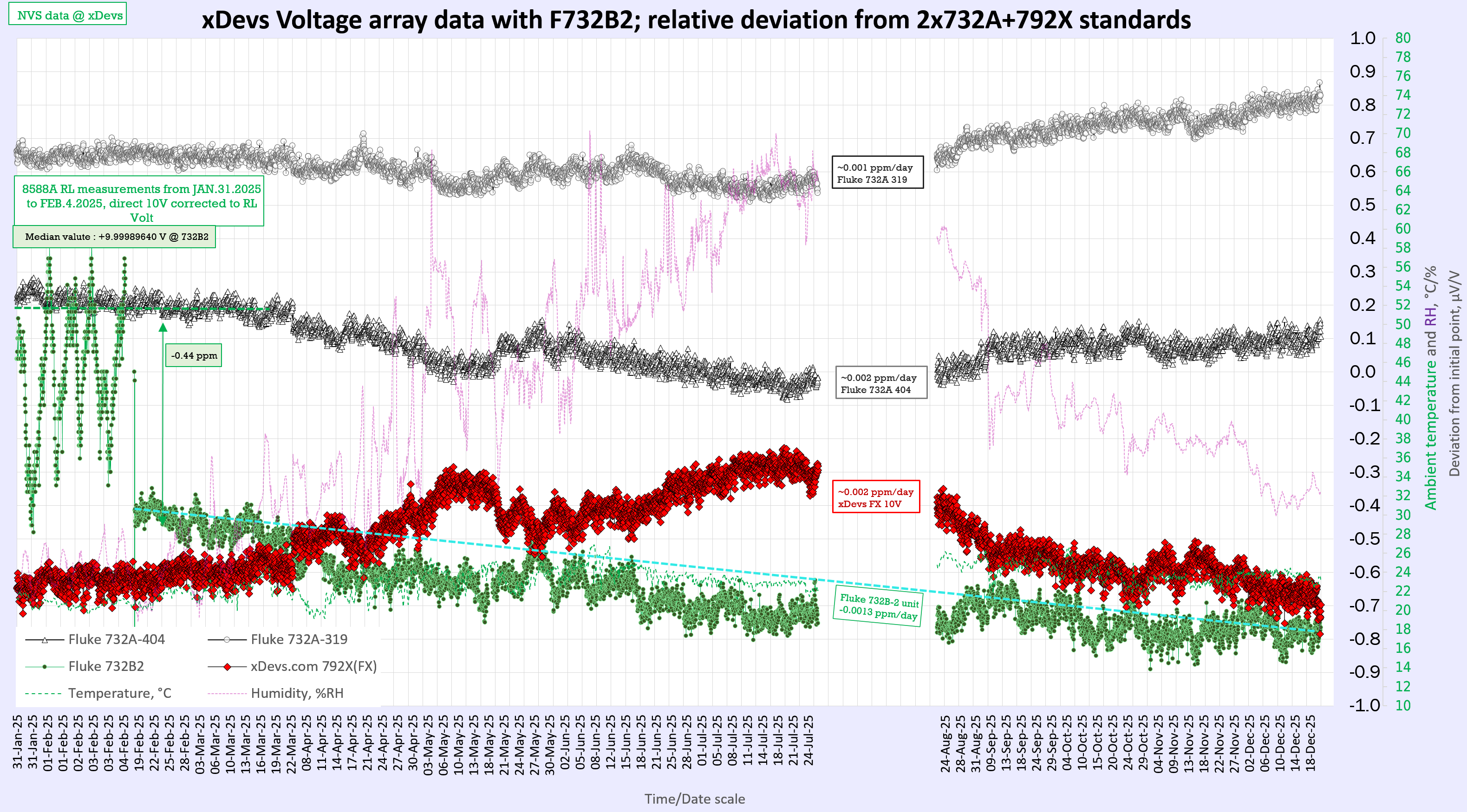
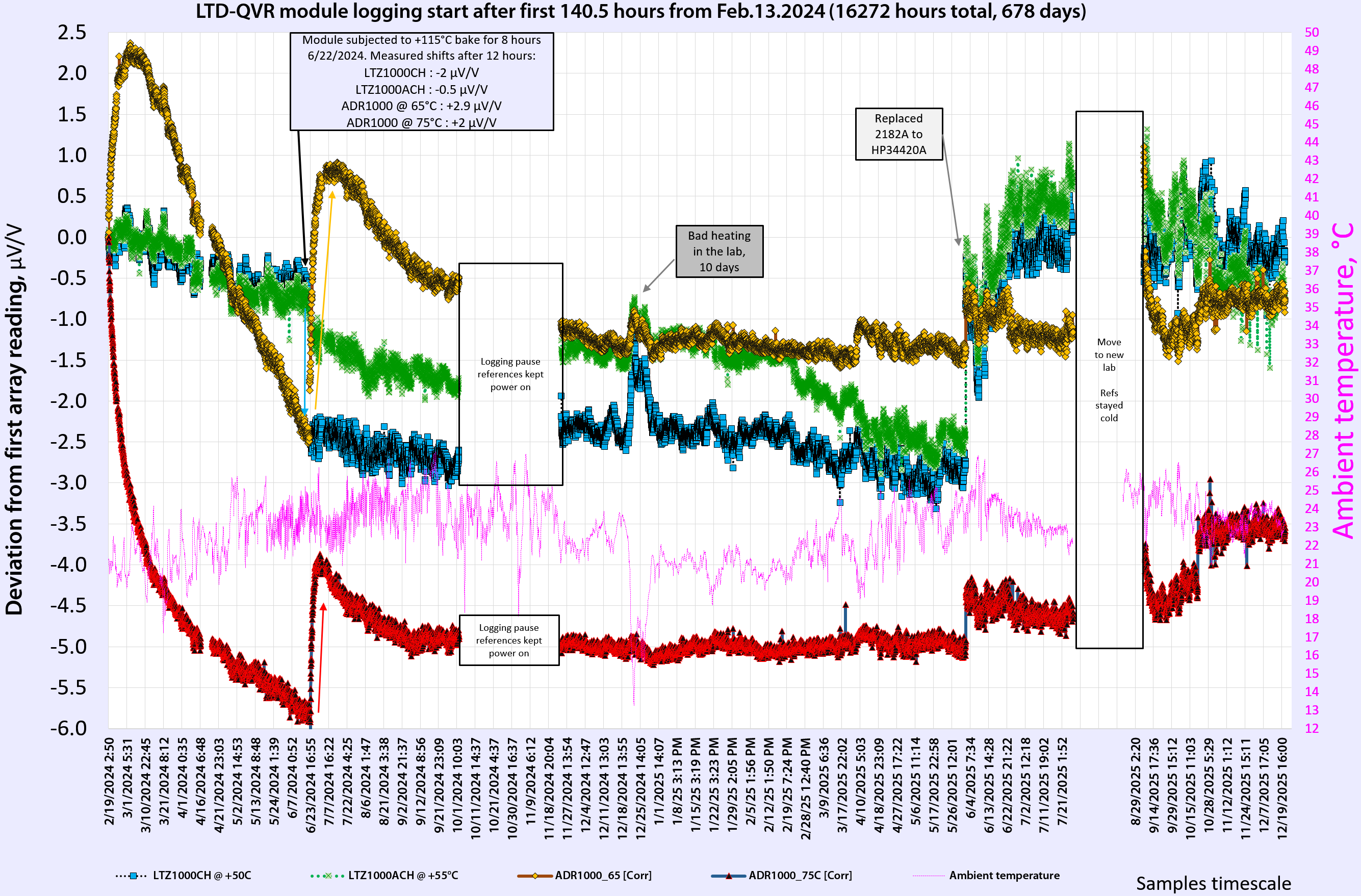
Comparisons and long-term drift data
Let’s take a look on top three zeners that are used as anchor standards and good known “keepers” of the voltage in my lab. Results of 10.5 million samples to make 29012 data points with nanovoltmeter since 12 November 2022 until 25 December 2025 can be rendered on the following charts.

Summary and conclusion
Many younger engineers and graduates today may neglect and disregard old era instruments, such as 40-year old Fluke 732A as antique boat anchor boxes. But thinking that modern shiny replacement is better in world of metrology often a deception.
Well cared Fluke 732A is still as capable as newest and fanciest Model 732C and actually capable offering something than NO new standard from factory can do. This capability is proven history of operation with decades of predictable and stable drift. All variants of 732 standards are still in wide use at calibration laboratories, used as DC voltage transport standards for transfers of the Volt between states and industry customers. Quantum standards are still quite expensive and specialized capital investment to appeal wider customer base. Hopefully in next decade or so this would change, but until then many of us can still rely on glorious Fluke 732A/B/C boxes.
Special thanks goes to long-term xDevs.com supporters Todd M., Igor O. and many more for participation in interlab comparisons for resistance and voltage metrology. What are your results with 732 type standards? How do you keep track of DC voltage stability in lab? Do you have history and data to share about your 732? With these and any other related questions – feel free to reach out to us at our own IRC chat server: xdevs.com (port 4808, channel: #xDevs.com) or via email
Projects like this are born from passion and a desire to share how things work. Education is the foundation of a healthy society - especially important in today's volatile world. xDevs began as a personal project notepad in Kherson, Ukraine back in 2008 and has grown with support of passionate readers just like you. There are no (and never will be) any ads, sponsors or shareholders behind xDevs.com, just a commitment to inspire and help learning. If you are in a position to help others like us, please consider supporting xDevs.com’s home-country Ukraine in its defense of freedom to speak, freedom to live in peace and freedom to choose their way. You can use official site to support Ukraine – United24 or Help99. Every cent counts.
Modified: Feb. 22, 2026, 8:44 p.m.