- Introduction
- Disclaimer
- Manuals and documents
- Repair for unit 1, Model 2400, S/N 1033544
- Repair for unit 2, Model 2400, S/N 14XXXXX, Firmware C32
- Repair for unit 3, Model 2400, S/N 724757, Firmware C14
- Repair for unit 4, Model 2400, S/N 978886, Firmware C26
- Repair for unit 5, Model 2420, S/N 821175, Firmware C21
- Repair for unit 6, Model 2425, S/N 816992, Firmware C33
- Repair for unit 7, Model 2425, S/N 1104387, Firmware C30
- A look inside destroyed Model 2400LV
- Bonus photos, Keithley 6430 sub-femtoamp remote SMU
- Performance benchmarks after repairs
- Conclusion and summary
Intro
A decade ago I was dreaming to own a SourceMeter in the lab for experiments, repairs and circuit development. That dream came to life a decade ago with the acquisition of a broken Keithley 2400 with shattered vacuum fluorescent display. After trivial repair with glass replacement from donor Keithley 7001 that SMU was calibrated by Tektronix, Taiwan and used by the xDevs.com lab many years since.
As lab capabilities evolved we now can adjust and calibrate this same Keithley 2400 in-house with a help of mighty HP 3458A 8½-digit DMM. In this article I’ll repair some more Keithley 2400 series SMUs as a recognition to their excellence and usefullness in any EE lab. I’ve decided to group information about each instrument into a dedicated chapter with focus on each instrument. I’ve also included calibration updates on my own now modified 2400 (with LM399 reference mod) and 2425.
Model 2400 series SMUs are still manufactured and sold new by the Keithley’s parent company, Tektronix. They are installed in hundreds of laboratories for both manual and automated operation. Tektronix is happy to encourage customers towards new feature-rich Model 2450 with bit smaller price tag. Maybe someday I’ll come across reasonably priced broken Model 2450 to investigate it’s redesigned internals and attempt a repair. But already I think that might be tricky with a use of dense FPGA, 32-bit heavily integrated microcontroller and complex layout. If you have broken 2450 series SMU, feel free to reach out for possibility of some collaboration for repair attempt.
But lot of industry labs still rely on old, yet still perfectly capable and running Model 2400’s. I hope this article can be useful for people who own these great ageing instruments and need information to keep them still working good. Number of the SourceMeters shown here are not mine but temporary visiting my lab for repairs, to help out my fellow hobby friends. I’ve learned a lot from repairing Keithley instruments and reading about them online in last 15 years and it is only fair to give some knowledge back to engineering community.
Disclaimer
Redistribution and use of this article, any parts of it or any images or files referenced in it, in source and binary forms, with or without modification, are permitted provided that the following conditions are met:
- Redistribution of this article must retain the above copyright notice, this list of conditions, link to this page (https://xdevs.com/fix/kei2400pp/) and the following disclaimer.
- Redistribution of files in binary form must reproduce the above copyright notice, this list of conditions, link to this page (https://xdevs.com/fix/kei2400pp/), and the following disclaimer in the documentation and/or other materials provided with the distribution, for example Readme file.
All information posted here is hosted just for education purposes and provided AS IS. In no event shall the author, xDevs.com site, or any other 3rd party, including Keithley/Tektronix be liable for any special, direct, indirect, or consequential damages or any damages whatsoever resulting from loss of use, data or profits, whether in an action of contract, negligence or other tortuous action, arising out of or in connection with the use or performance of information published here.
If you willing to contribute or add your experience regarding instrument repairs or provide extra information, you can do so following these simple instructions
Manuals
Sadly there is no detailed service information about 24xx series SMUs available. Even diagnostic self-test is hidden behind the manufacturing mode , perhaps due to safety reasons as Model 2400 can source over 200V which can be very dangerous for the user. We still can learn quite a bit from other manuals about functions and operation of 2400, and use that knowledge to troubleshoot the SMU. Plus I still have my old original trusted Keithley 2400 in the lab for reference. xDevs lab also has repaired Keithley 2425 which is higher current flavour of 2400 SMU series.
Model 2400 series User’s manual, Rev.K, September 2011
Model 2400 series Service Manual, Rev.D, November 2000, no schematics
Model 2400 series Quick Results Guide, Rev.C, 2002
Model 2410 Service Manual, Rev B, July 1998, no schematics
Model 2410 and 2410-C Specifications sheet, Rev.D, 2003
Keithley 2425 100W Service manual
Repair for unit 1, Model 2400, S/N 1033544
First unit, from year of manufacture around year 2006. It was aquired by my good friend David on eBay and sent to my lab for troubleshooting and calibration.
This instrument was repaired quickly more than a year ago in January 2024 and shipped out long time ago as well. I don’t have much photos of it, since it was quick 30 minute repair with single faulty component replacement.
Meter was failing bunch of 40x series self-tests and was repaired by one bad relay fix. I have stolen the component from parts donor Keithley 2001 7½-digit DMM which has the very same part-number relays.
Original reed relay had still good coil but the contacts probably were damaged or worn out and not making a contact anymore.
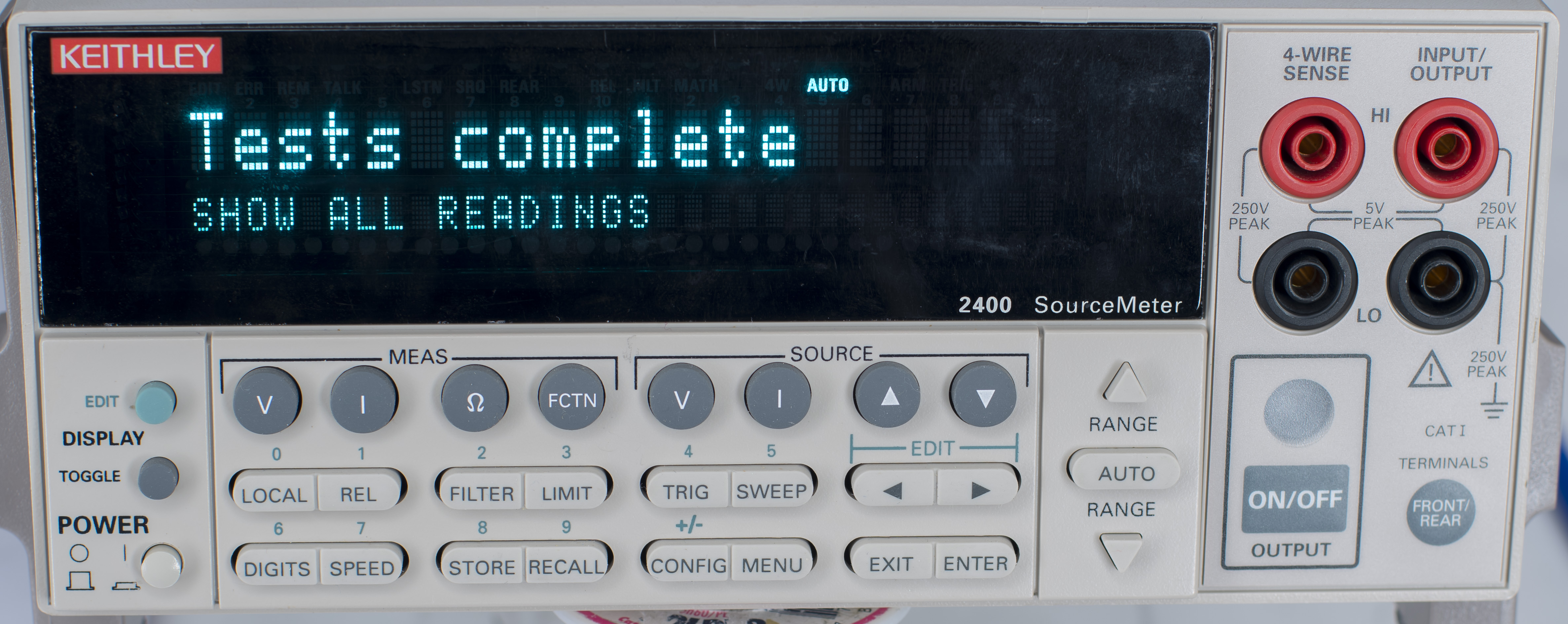
VFD display is nice and bright, with plenty of life left in it. After relay replacement unit fully returned to function and was recalibrated with 3458A.
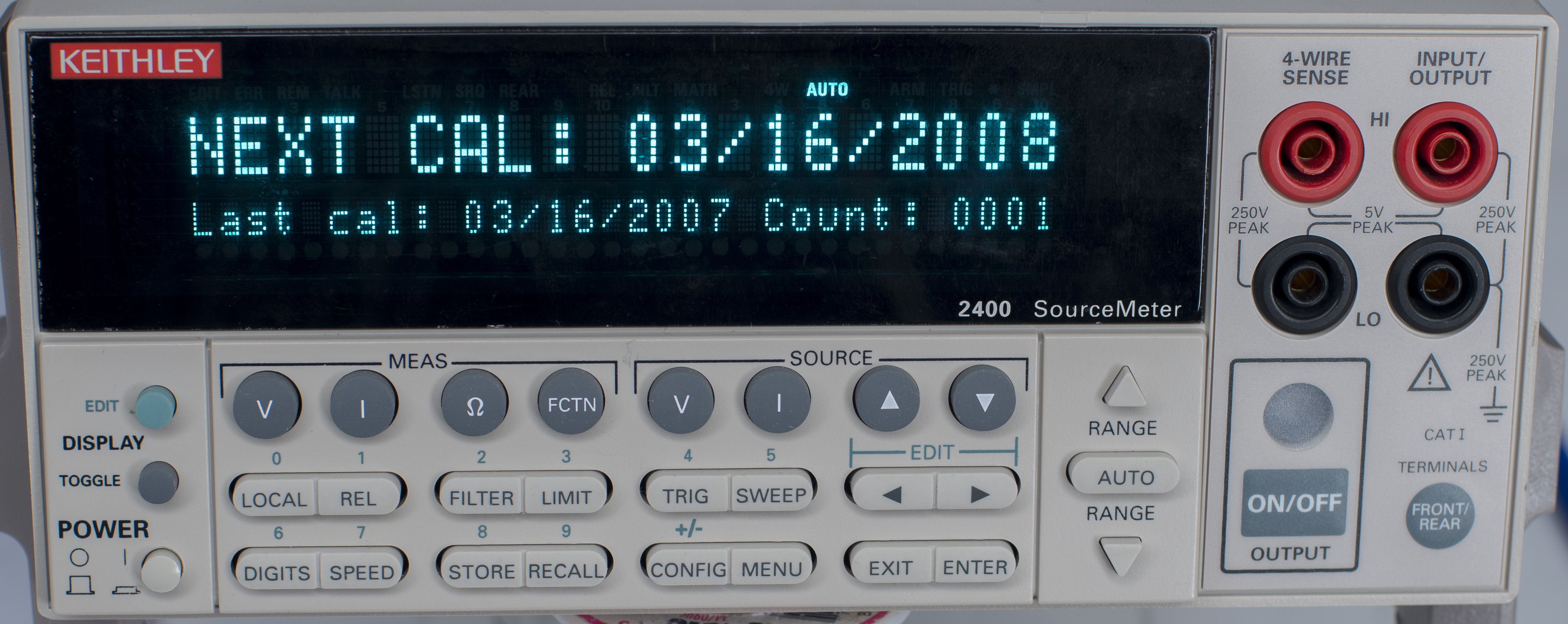
Original calibration was done in March 16, 2007.
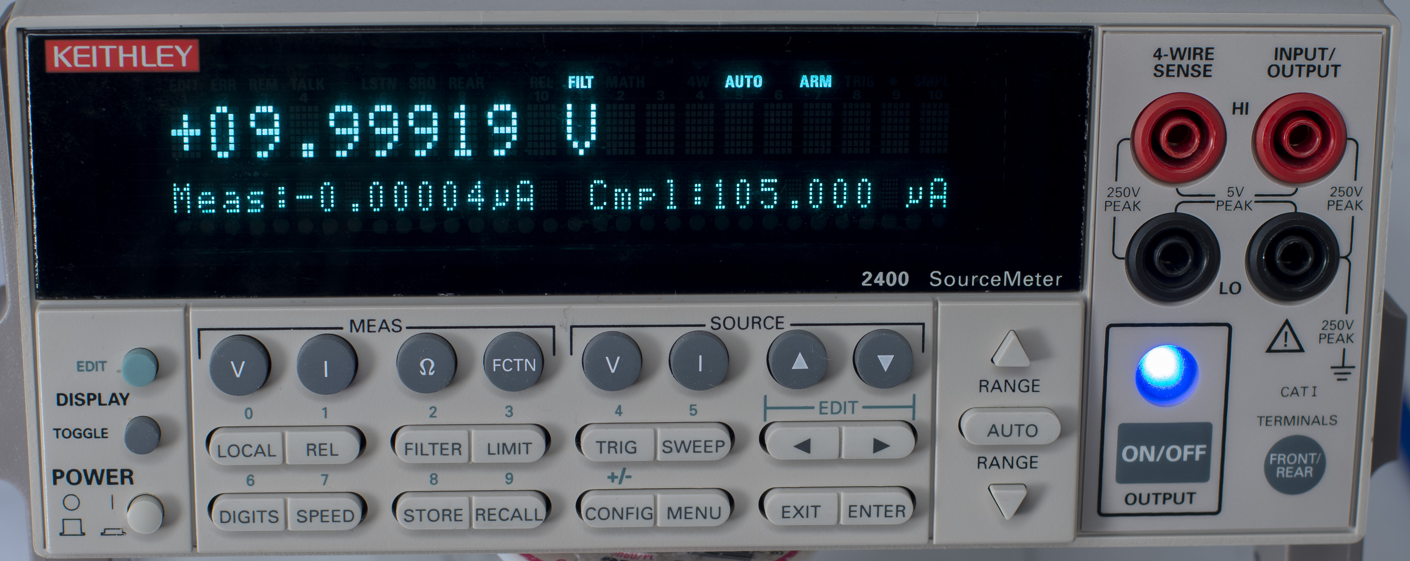
Mandatory +10 V source/measure level test:
Now this instrument is happy working we can test it with automated calibration script, determining if adjustment is required after the completed repair. Model 2400 SMU can be verified with a reference DMM for calibration and adjustment, in which case I will use the golden HP 3458A 8½-digit DMM. In calibration procedure SMU sourcing full-scale negative and positive voltages and zero in both polarity on each range, as well as full-scale positive/negative currents. DMM measures output voltage or current and reading is fed back to SMU as reference. No other external equipment is necessary for this process except pair of leads to interconnect DMM and SMU.
There are 16 steps for DCV calibration and 28 steps for DCI calibration, with 4 steps for each function range. It’s easy to make mistake and time consuming calibration with manual front-panel operation, so I wrote a simple calibration helper program in Python to automate this process. If you need to know details of calibration procedure steps, you can reference to Keithley Model 2400 Service Manual
Prerequisites for automated script:
- Reference HP 3458A (GPIB address 3)
- Keithley Model 2400 as DUT (GPIB address 24)
- GPIB cable to connect both and GPIB USB dongle (in my case it was NI USB-GPIB-HS)
- Raspberry Pi (I used 1 Model B, rev.2) running Jessie linux
- linux-gpib configured and working (ibtest tool can connect to instruments properly)
Python script used for this SMU calibration
Important note about use of proper metrology terminology. In user manuals many manufacturers are using misleading terms for important operations such as calibration. Per international standards calibration is only a comparison of unknown measurand to known reference standard, with a goal to determine degree of agreement within the uncertainty between the two. Contrary to wording used in many manuals, calibration never involves any adjustments to alter the measurand from the device under test.
If you take a known reference standard, such as resistor with assigned value, connect it to DMM, document the reading from this DMM – now you got a calibrated DMM with accuracy traceable to your reference standard. This is a very important difference to understand, and when you send instrument for calibration, you should expect only verification procedures to be done one it. If you specifically need adjustments, for example to bring instrument closer to factory specifications, be sure to specifically state that adjustment is required. This would also double the amount of work that laboratory would need to perform, since instead of single calibration run they now would need to perform three operations – calibration before adjustments, adjustment operations, calibration after adjustments. Good calibration laboratory would provide you with not one but TWO certificates in case of adjustments done, one showing data before and one after. This commonly referred as “AS RECEIVED” and “AS RETURNED” condition.
In Keithley’s own Model 2400 service manual actual calibration procedures are called “Performance verification”, while adjustment procedure is incorrectly called “Calibration”. Keep this meaning discrepancy in termins in mind when reading the manual. Using proper terms is needed to better communicate, to properly compare information among different people and to keep correct interpretation of measurement in time and across nations/languages. Official terminology is outlined and detailed in publications by BIPM JCGM with key document being JCGM 200:2012 International Vocabulary of Metrology – Basic and general concepts and associated terms
Script has some configuration parameters for user settings in the beginning of .py file. Main functionality is split into three main operations:
- Calibration in “as received” condition, before any adjustments procedures
- Optional adjustment procedure, performed in sequence outlined in Keithley official service manual
- If adjustment is performed, additional calibration in “as adjusted” condition, in case of success.
All internal calibration value constants for each range are also dumped into log for future reference purposes. Additionally record of current timestamp, instrument serial number, firmware version and boards revision are stored for traceability record.
-i- Script started 30/01/2024-21:37:17;
Keithley Model 2400 - detected, S/N 1033544, Version: C27   Feb  4 2004 14:58:04/A02  /K/H
Keithley Model 2400 - last date calibrated 2007,03,16
Keithley Model 2400 - last due calibrated 2008,03,16
==== K2400 Calibration constants data
0.2 DCV Range, SENS:DATA? = -1.248670E+00,-1.867115E-05,-1.248691E+00,+0.000000E+00
0.2 DCV Range, SOUR:DATA? = +3.045006E+05,+8.995742E+02,-3.045085E+05,+1.015680E+03
2.0 DCV Range, SENS:DATA? = -1.248637E+00,-1.621246E-05,-1.248729E+00,+0.000000E+00
2.0 DCV Range, SOUR:DATA? = +3.042015E+04,+2.058906E+02,-3.042095E+04,+2.176250E+02
20.0 DCV Range, SENS:DATA? = -1.248636E+01,+1.409531E-03,-1.248719E+01,+0.000000E+00
20.0 DCV Range, SOUR:DATA? = +3.042055E+03,+2.010469E+02,-3.042167E+03,+2.222109E+02
200.0 DCV Range, SENS:DATA? = -1.248568E+02,+1.502991E-02,-1.248666E+02,+0.000000E+00
200.0 DCV Range, SOUR:DATA? = +3.042269E+02,+2.007500E+02,-3.042345E+02,+2.225078E+02
1.0e-06 DCI Range, SENS:DATA? = -6.235608E-07,-1.244871E-10,-6.236069E-07,+0.000000E+00
1.0e-06 DCI Range, SOUR:DATA? = +6.091232E+10,+2.194141E+02,-6.090831E+10,+2.137148E+02
1.0e-05 DCI Range, SENS:DATA? = -6.265383E-06,-1.018634E-09,-6.265730E-06,+0.000000E+00
1.0e-05 DCI Range, SOUR:DATA? = +6.062278E+09,+2.180742E+02,-6.061941E+09,+2.156914E+02
1.0e-04 DCI Range, SENS:DATA? = -6.243317E-05,-9.196810E-09,-6.243762E-05,+0.000000E+00
1.0e-04 DCI Range, SOUR:DATA? = +6.083709E+08,+2.174922E+02,-6.083315E+08,+2.158594E+02
1.0e-03 DCI Range, SENS:DATA? = -6.228008E-04,-8.835923E-08,-6.228409E-04,+0.000000E+00
1.0e-03 DCI Range, SOUR:DATA? = +6.098662E+07,+2.173047E+02,-6.098333E+07,+2.158242E+02
1.0e-02 DCI Range, SENS:DATA? = -6.242862E-03,-9.089708E-07,-6.243302E-03,+0.000000E+00
1.0e-02 DCI Range, SOUR:DATA? = +6.084151E+06,+2.174336E+02,-6.083803E+06,+2.155039E+02
1.0e-01 DCI Range, SENS:DATA? = -6.242391E-02,-8.843839E-06,-6.242901E-02,+0.000000E+00
1.0e-01 DCI Range, SOUR:DATA? = +6.084607E+05,+2.172617E+02,-6.084174E+05,+2.159453E+02
1.0e+00 DCI Range, SENS:DATA? = -6.250051E+00,-9.227991E-04,-6.250074E+00,+0.000000E+00
1.0e+00 DCI Range, SOUR:DATA? = +6.083479E+04,+9.730195E+02,-6.083634E+04,+9.550938E+02
Now let’s look at the results of calibration test for “as received” state after repair. Reference 3458A is never powered off, there was no need to wait for warm-up time. DUT Keithley 2400 was running for a day to get everything nice and stable. I’ve kept original firmware version C27 in this instrument to save some time. Hardware board revisions were K and H. Calibration was performed on January 30, 2024.
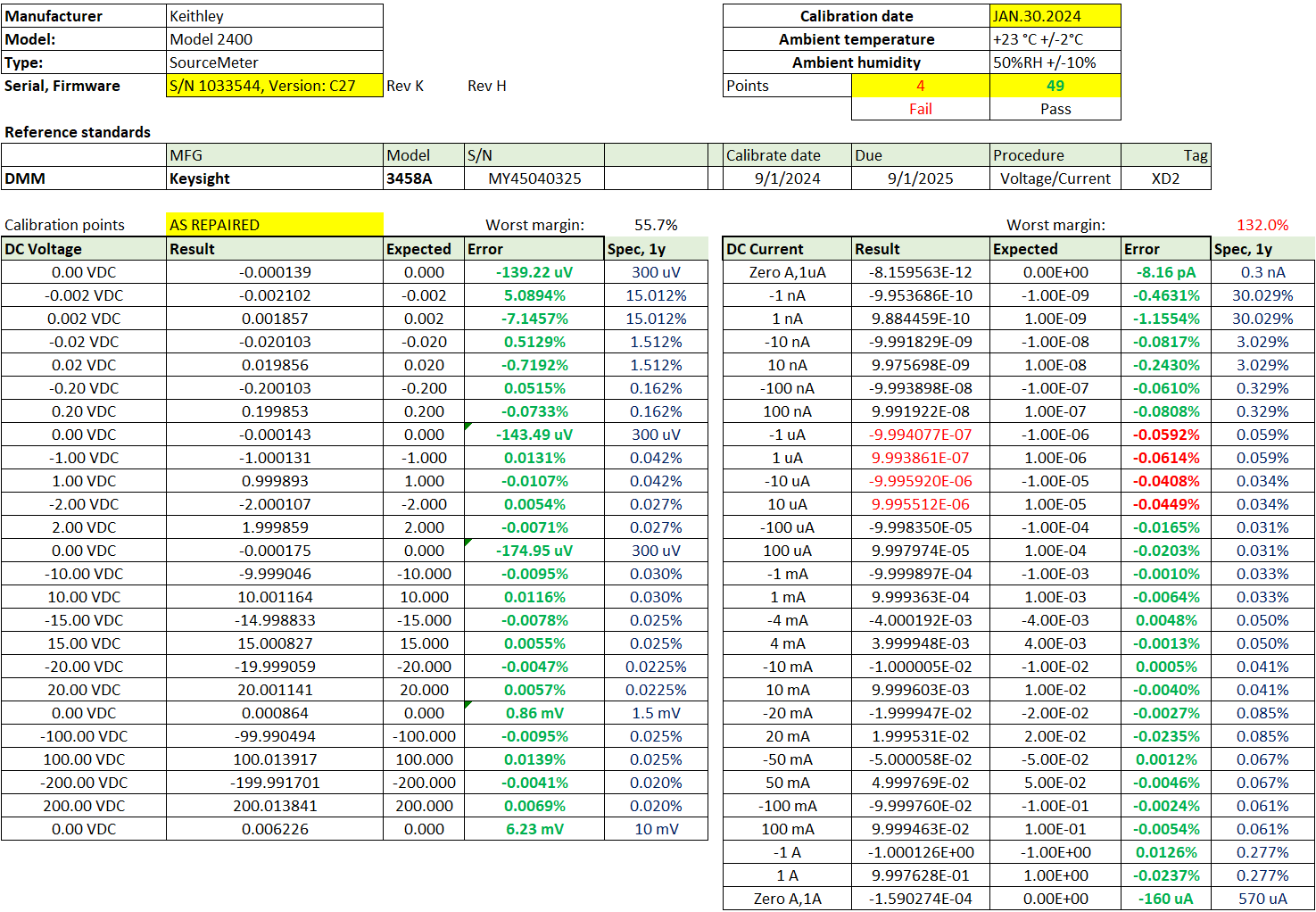
Based on these results we can see that SourceMeter still working mostly good and most of the ranges were able to meet annual specifications published by Keithley documentation. All voltage ranges were within expected annual specification limits. Most sensitive current ranges at 1 µA and 10 µA levels failed to meet the specifications. Worst error was 132% for positive 1 µA point. Since there was no metrology history for this SMU, I’ve obtained consent from the owner of this instrument to perform adjustment.
After performing adjustment as outlined in Keithley’s service manual with the same HP 3458A 8½-digit DMM we got following set of new constants, automatically calculated and stored by SMU’s firmware. These constants are stored in I2C EEPROM on digital board of the Model 2400. This EEPROM memory is non-volatile and does not go bad with dead coin 3V battery.
New calibration “as returned” was completed shortly after adjustment, so in a working 2400 we should have zero issues meeting all the specifications with a good margin.
Keithley Model 2400 - last date calibrated 2024,01,30
Keithley Model 2400 - last due calibrated 2025,01,30
==== K2400 Calibration constants data
0.2 DCV Range, SENS:DATA? = -1.248682E+00,-1.365095E-04,-1.248672E+00,+0.000000E+00
0.2 DCV Range, SOUR:DATA? = +3.045046E+05,+9.434570E+02,-3.045222E+05,+9.811953E+02
2.0 DCV Range, SENS:DATA? = -1.248650E+00,-1.366138E-04,-1.248739E+00,+0.000000E+00
2.0 DCV Range, SOUR:DATA? = +3.041981E+04,+2.102656E+02,-3.042063E+04,+2.140508E+02
20.0 DCV Range, SENS:DATA? = -1.248646E+01,+2.590179E-03,-1.248740E+01,+0.000000E+00
20.0 DCV Range, SOUR:DATA? = +3.041995E+03,+1.982656E+02,-3.042066E+03,+2.261133E+02
200.0 DCV Range, SENS:DATA? = -1.248584E+02,+2.630615E-02,-1.248677E+02,+0.000000E+00
200.0 DCV Range, SOUR:DATA? = +3.042169E+02,+1.980273E+02,-3.042234E+02,+2.262734E+02
1.0e-06 DCI Range, SENS:DATA? = -6.231806E-07,-1.227818E-10,-6.232244E-07,+0.000000E+00
1.0e-06 DCI Range, SOUR:DATA? = +6.094934E+10,+2.194570E+02,-6.094564E+10,+2.120234E+02
1.0e-05 DCI Range, SENS:DATA? = -6.262581E-06,-9.667929E-10,-6.263017E-06,+0.000000E+00
1.0e-05 DCI Range, SOUR:DATA? = +6.064997E+09,+2.177305E+02,-6.064620E+09,+2.136172E+02
1.0e-04 DCI Range, SENS:DATA? = -6.242076E-05,-8.978532E-09,-6.242549E-05,+0.000000E+00
1.0e-04 DCI Range, SOUR:DATA? = +6.084886E+08,+2.176680E+02,-6.084502E+08,+2.140352E+02
1.0e-03 DCI Range, SENS:DATA? = -6.227710E-04,-9.289943E-08,-6.228118E-04,+0.000000E+00
1.0e-03 DCI Range, SOUR:DATA? = +6.098946E+07,+2.176133E+02,-6.098598E+07,+2.138359E+02
1.0e-02 DCI Range, SENS:DATA? = -6.242706E-03,-9.387732E-07,-6.243160E-03,+0.000000E+00
1.0e-02 DCI Range, SOUR:DATA? = +6.084285E+06,+2.177539E+02,-6.083902E+06,+2.138008E+02
1.0e-01 DCI Range, SENS:DATA? = -6.242106E-02,-9.454787E-06,-6.242564E-02,+0.000000E+00
1.0e-01 DCI Range, SOUR:DATA? = +6.084862E+05,+2.178359E+02,-6.084487E+05,+2.137109E+02
1.0e+00 DCI Range, SENS:DATA? = -6.249713E+00,-9.647608E-04,-6.249489E+00,+0.000000E+00
1.0e+00 DCI Range, SOUR:DATA? = +6.083812E+04,+9.784180E+02,-6.084372E+04,+9.354141E+02
And finally to results of each measured point, with margin checks data. Previosly failing 1 µA and 10 µA are now almost perfect with just 8 µA/A deviation from nominal.
Everything now met annual specifications with very good margins, as expected. This instrument was packed up and sent to my friend David for his hobby lab use and enjoyment. Hopefully this Model 2400 will be serving him well for years to come.
Repair for unit 2, Model 2400, S/N 14XXXXX, Firmware C32
This instrument is much newer and sports new dark-grey Tektronix colors for outer cover and plastic parts. After acquisition by Tektronix Keithley instruments were refreshed to new grey colors instead of traditional light-beige industrial design. Perhaps this styling change was done for a better blend with other vendors test equipment on the bench, so I don’t have to fiddle with white color balance in photograph editing as much :).
Somebody put some nasty stickers and labels on top cover of the SMU. It took me a while to get everything cleaned with IPA 99% solution. I don’t like dealing with large stickers with strong adhesives.
On the rear this insturment is nice and clean. Everything design-wise is exactly identical to original Keithley boxes, no surprises from the outside.
Reason for this instrument to be in this repair article is the obvious one: “No Comm Link” error message on display after some noticeable power-on delay.
This suggests lack of communication between front panel microcontroller and main processor brains of the instrument on digital bottom board. Front panel board has it’s own small controller that runs the display and if serial datalink to main processor timeout for any reason, it prints this simple static error message on the screen. I’ve checked front panel separately by connecting it to another working SourceMeter box and it greeted me with proper boot-up messages. This confirms good health of front panel board and points us to the faulty digital motherboard assembly in this Model 2400.
Perhaps a power supply or firmware issue? I could think of one possible reason for this fault – power/user failure during firmware update procedure, which might cause corruption of the firmware. This reminds me of the fault I had with Keithley 2510 TEC SMU. It will take a little bit of work to get down to digital/power supply board in K2400. Analog board is on top and comes out first in these instruments. It’s rather simple disassembly with just two bolts at the heatsink side and two bolts near front/rear cabling side. Don’t remove any other bolts on PCB as they hold the guard shield plate under the board.
Now it’s quite interesting that this much newer unit has LM399 as main reference. This is quite a difference compared to older 2400 which had just selected 1N829 zener diode. Perhaps at some point Keithley ran out of the good pile of old zeners and decided to move for proper ovenized LM399 reference? I can see a footprint near it for TO-92 device as well, so perhaps there was some other options too. It would be interesting to compare noise performance of this 2400 with factory-built LM399 version to our old 2400 that I modified to LM399 myself and to stock old 2400 with 1N829 zener.
ADC itself is also cost-optimized Keithley custom ASIC in small TQFP package. This is essentially Keithley 2000 6½-digit multislope solution that Keithley reused in many many instruments. We still can see the footprint for much larger but functionally equivalent legacy implementation with ALTERA MAX EPM7160 CPLD logic device, like on old Model 2400.
Front-end and analog circuitry is mostly identical to old SMU as well, with some parts updated to modern replacements, few added GDT near output cables for protection and some resistor networks replaced to SOIC type networks. Few opamps in DIP8 package got also updated to SOIC SMT alternatives. Obsoleted LT1124 and LT1097 got replaced with Analog Devices AD8672A. AD795J also got replaced with TI OPA124U for U262 position. According to chips datecodes this analog board was manufactured around week 17 of 2012.
Power regulator for output stage at the analog board corner is unchanged as well. Digital multiplexers for signal routing remained the same, mostly DG444 and DG408 in SOIC16 packages, as these parts are still in production even today.
Switchmode mains power supply has same manufacturer and model. This SMPS provides +5 and +12 VDC to outguard earth-referenced logic use, as well as DC/DC block to generate isolated +5, +15 and -15 power rails for in-guard. These rails are regulated with linear National Semiconductor LM2940CT and LM2990CT chips in TO-220 mounted on small aluminum heatsinks. This all is done around switching transformer TR-302B1 driven by pair of IRFIZ34G transistors nearby on digital board.
Overall digital board is nice and clean, with couple updated parts here and there. There are personality label on silkscreen and couple of jumper-links to configure board as Model 2400, Model 2401 (low cost model) or Model 2410 (1kV SMU version). PCB was manufactured in China by China Circuit Technology (SHANTOU) Corp in workweek 19 of year 2012. Part-number for this exact digital motherboard is 2400-142K, meaning Revision K. Most of the components have datecodes around 2010-2011.
Digital board also had minor changes, such as replacement of old DS1236S RTC chip to modern Maxim MAX6365PKA46* in SOT23-8 package with marking AAAN. Memory chips are now soldered down SST 39SF020A Flash in PLCC32 instead of socketed positions like in the old K2400. Main processor is still same Motorola/Freescale MC68332 in TQFP134 package.
Checking Flash memory contents revealed good firmware data, matching factory labels for version C32. I’ve read both chips multiple times and binary readout matched expected data perfectly. So whatever problem is with this processor board not booting is not a corrupt firmware in Flash ROMs. Probing around with oscilloscope confirmed good 32768 Hz from Y1 oscillator. Because firmware PLCC32 Flash firmware chips were desoldered, I’ve decided to put back sockets to make firmware changes/upgrades easier later on.
But replacing firmware chips didn’t help, instrument still refused to boot. Checking U13 and GPIB buffers has not offered any progress either. Only bits left at this point were SRAM chips or main processor. Processor is still available on Digikey for a lot of money but SRAM chips are cheap. I can also steal them from another broken parts donor Model 2400 that was left over from another repair project.
Replacing SRAMs did the trick and SMU started booting procedure with a happy buzzer beep and all segments lit on VFD screen. I’ve connected analog board assembly with metalwork frame back into the chassis and ran BIST mulitple times in continous mode without a single fault. This is now yet another revived SourceMeter.
BIST procedure require four-wire short attached to either front or rear terminals for proper operation. At this point I’ve reassembled everything back together, cleaned all the covers and panels and sealed the box. Dead parts are left as a bonus to the insturment’s owner or a reminder that even non-obvious things like memory chips can fail.
During repair I love to use my programmable Chroma 61604 AC power source. It’s very handy for testing power supplies and checking if equipment operate in all various international voltage levels, like higher 220 V in Ukraine or 100 V in Japan.
Chroma 61604 also reports power analysis stats, which is useful to check if there are any hidden sneaky issues with input SMPS or just to check efficiency. Model 2400 configured for +10 V output with nothing connected consumes about 19.2 W of power since it’s mostly linear device with lot of analog circuitry around the complex output power stage. Extra bonus for people who can rec
Calibration and performance test results
Python script used for this SMU calibration, Rev 9
Script output log, as received data
Script output log, adjustment steps and as returned data data
Calibration report results for this 2400, June 5, 2025
Just like before all internal calibration value constants for each range are also dumped into log for future reference purposes. Additionally record of current timestamp, instrument serial number, firmware version and boards revision are stored for traceability record.
-i- Script settings : 16 samples, 20 DMM NPLC, 0 ACAL run, skip_precal 0, skip_postcal 0
-i- Script started 05/06/2025-22:00:54;
Keithley Model 2400 - detected, S/N 14XXXXX, Version: C34 Sep 21 2016 15:30:00/A02  /S/K
Keithley Model 2400 - last date calibrated 2012,08,02
Keithley Model 2400 - last due calibrated 2013,08,02
==== K2400 Calibration constants data
0.2 DCV Range, SENS:DATA? = -1.402909E+00,+3.454089E-04,-1.402933E+00,+0.000000E+00
0.2 DCV Range, SOUR:DATA? = +2.928878E+05,+9.065977E+02,-2.928659E+05,+9.485234E+02
2.0 DCV Range, SENS:DATA? = -1.402849E+00,+3.454685E-04,-1.402986E+00,+0.000000E+00
2.0 DCV Range, SOUR:DATA? = +2.927118E+04,+2.069062E+02,-2.926885E+04,+2.111992E+02
20.0 DCV Range, SENS:DATA? = -1.402886E+01,-1.407623E-03,-1.403024E+01,+0.000000E+00
20.0 DCV Range, SOUR:DATA? = +2.927041E+03,+2.212422E+02,-2.926813E+03,+1.968281E+02
200.0 DCV Range, SENS:DATA? = -1.402827E+02,-1.713562E-02,-1.402961E+02,+0.000000E+00
200.0 DCV Range, SOUR:DATA? = +2.927190E+02,+2.221133E+02,-2.926956E+02,+1.960000E+02
1.0e-06 DCI Range, SENS:DATA? = -7.012431E-07,-2.273737E-12,-7.013025E-07,+0.000000E+00
1.0e-06 DCI Range, SOUR:DATA? = +5.855583E+10,+2.142031E+02,-5.855737E+10,+1.929570E+02
1.0e-05 DCI Range, SENS:DATA? = -7.039309E-06,+2.091838E-11,-7.039976E-06,+0.000000E+00
1.0e-05 DCI Range, SOUR:DATA? = +5.833228E+09,+2.139687E+02,-5.833386E+09,+1.926289E+02
1.0e-04 DCI Range, SENS:DATA? = -7.010822E-05,+3.201421E-10,-7.011496E-05,+0.000000E+00
1.0e-04 DCI Range, SOUR:DATA? = +5.856935E+08,+2.139141E+02,-5.857071E+08,+1.927852E+02
1.0e-03 DCI Range, SENS:DATA? = -7.001236E-04,+3.259629E-09,-7.001953E-04,+0.000000E+00
1.0e-03 DCI Range, SOUR:DATA? = +5.864945E+07,+2.139180E+02,-5.865042E+07,+1.928711E+02
1.0e-02 DCI Range, SENS:DATA? = -7.020132E-03,-5.587935E-09,-7.020791E-03,+0.000000E+00
1.0e-02 DCI Range, SOUR:DATA? = +5.849151E+06,+2.141563E+02,-5.849297E+06,+1.925938E+02
1.0e-01 DCI Range, SENS:DATA? = -7.019130E-02,+2.831221E-07,-7.019818E-02,+0.000000E+00
1.0e-01 DCI Range, SOUR:DATA? = +5.849993E+05,+2.139102E+02,-5.850133E+05,+1.926953E+02
1.0e+00 DCI Range, SENS:DATA? = -7.000141E+00,+1.430511E-06,-7.000188E+00,+0.000000E+00
1.0e+00 DCI Range, SOUR:DATA? = +5.871059E+04,+9.839102E+02,-5.871486E+04,+7.688242E+02
Benchmarking this instrument against my HP3458A shows that everything works as expected with every range.
Keithley Model 2400 - last date calibrated 2025,06,05
Keithley Model 2400 - last due calibrated 2026,06,05
==== K2400 Calibration constants data
0.2 DCV Range, SENS:DATA? = -1.402901E+00,+2.862215E-04,-1.402928E+00,+0.000000E+00
0.2 DCV Range, SOUR:DATA? = +2.928988E+05,+9.259180E+02,-2.928767E+05,+9.219297E+02
2.0 DCV Range, SENS:DATA? = -1.402843E+00,+2.844334E-04,-1.402970E+00,+0.000000E+00
2.0 DCV Range, SOUR:DATA? = +2.927178E+04,+2.089297E+02,-2.926957E+04,+2.086562E+02
20.0 DCV Range, SENS:DATA? = -1.402878E+01,-1.930237E-03,-1.403005E+01,+0.000000E+00
20.0 DCV Range, SOUR:DATA? = +2.927101E+03,+2.229609E+02,-2.926885E+03,+1.946680E+02
200.0 DCV Range, SENS:DATA? = -1.402805E+02,-2.189636E-02,-1.402934E+02,+0.000000E+00
200.0 DCV Range, SOUR:DATA? = +2.927282E+02,+2.236602E+02,-2.927054E+02,+1.939414E+02
1.0e-06 DCI Range, SENS:DATA? = -7.011257E-07,+2.160050E-11,-7.011869E-07,+0.000000E+00
1.0e-06 DCI Range, SOUR:DATA? = +5.856658E+10,+2.115703E+02,-5.856846E+10,+1.942773E+02
1.0e-05 DCI Range, SENS:DATA? = -7.037669E-06,-3.819878E-11,-7.038331E-06,+0.000000E+00
1.0e-05 DCI Range, SOUR:DATA? = +5.834703E+09,+2.130234E+02,-5.834842E+09,+1.928008E+02
1.0e-04 DCI Range, SENS:DATA? = -7.008993E-05,-6.475602E-10,-7.009650E-05,+0.000000E+00
1.0e-04 DCI Range, SOUR:DATA? = +5.858545E+08,+2.132578E+02,-5.858692E+08,+1.926250E+02
1.0e-03 DCI Range, SENS:DATA? = -6.999815E-04,-7.450581E-09,-7.000478E-04,+0.000000E+00
1.0e-03 DCI Range, SOUR:DATA? = +5.866216E+07,+2.133555E+02,-5.866361E+07,+1.925508E+02
1.0e-02 DCI Range, SENS:DATA? = -7.018247E-03,-9.778887E-08,-7.018890E-03,+0.000000E+00
1.0e-02 DCI Range, SOUR:DATA? = +5.850821E+06,+2.134883E+02,-5.850973E+06,+1.924531E+02
1.0e-01 DCI Range, SENS:DATA? = -7.017455E-02,-1.110137E-06,-7.018088E-02,+0.000000E+00
1.0e-01 DCI Range, SOUR:DATA? = +5.851490E+05,+2.135937E+02,-5.851664E+05,+1.923594E+02
1.0e+00 DCI Range, SENS:DATA? = -6.999813E+00,-1.304150E-04,-7.000062E+00,+0.000000E+00
1.0e+00 DCI Range, SOUR:DATA? = +5.871448E+04,+9.790508E+02,-5.871804E+04,+7.629648E+02
Results as adjusted improved quite a bit, with worst margin on current ranges going from 90.3% of the factory spec down to comfortable 26.2%.
One more happy SourceMeter Model 2400 can now return to the fleet and serve the owner well.
I have also performed additional tests for linearity on main 10 V range, as I was curious to see if there are any difference relative to better LM399 reference in this device. I love running linearity tests as they showcase much better approach to understand the performance of the instrument across the whole tested range, with better confidence in results compared to few very specific “nominal” full-scale test points like typical calibration report provides. These tests require much more time and can be tedious to do properly for high performance gear, but it can be also fun to explore the limits of equipment. Again automation comes in and saves a day for performance benchmarks like this.
Python script for capturing random INL datapoints for DUT K2400 and three HP3458A DMM
Non-linearity tests are explained and covered in decent detail in this dedicated article. Matplot,numpy and scipy libraries are required for this Python3 script.
Plotter for INL analytics, for this K2400 test sweep
Configuration of the program, input filename, plotting parameters and chart scales are defined in separate configuration file linkit_11_2400.conf. Make sure it is placed in same folder to linearity_plot.py program.
Configuration file for K2400 INL plotter
And finally the meat of the experiment, dataset with every captured point, standard deviation of readings and environmental data during each point measurement. Total 1640 points were captured between June 5, 2025 23:28:16 and June 6, 2025 11:42:49. Also there was no need to use whole tandem of three different 3458A’s for this test since DC voltage performance of even one 3458A is two magnitudes better than Sourcemeter’s output.
DSV-file with all INL datapoints, relative to three HP3458A
All this stuff generates following pretty chart. Top plot shows measured non-linearity error relative to linear best fit, middle plot displays standard deviation for ±1 σ and bottom plot displays ambient environment temperature during the test point capture from digital THP Bosch BME280 sensor.
Overall Model 2400 has a bit of triangular non-linearity across the points from -11 to +11 V. SourceMeter is not a high stability calibrator, but more of a power source device so we shouldn’t expect single µV/V stability in here. Overall data shows no significant outlier on any point with typical noise standard deviation less than a microvolt. Every single random voltage was inside of ±100 µV/V limit which is 0.01%. To remind you, factory specification from Keithley for 10 V sourced using main 21 V range is 0.03%, so we are already 3 times better than spec in this dataresult.
Exterior for unit 3
This unit is similar to unit 1. Has couple of stickers from Keysight and CSA inspection label. Based on serial number and past experience with 2400 series it is manufactured prior to year 2000.
Diagnostics and repair for unit 1
After enabling secret diagnosis mode and running a self test instrument reported whole row of faults, starting with test 300.2. Due to safety reasons self-diagnostic procedures and functional self-tests are hidden and must be accessed in unlocked secret mode. This was shown before here but for clarity will duplicate information here as well. On 2400 series SMUs entering secret mode is done by two buttons:
1. Ensure unit is powered off.
2. Press and hold gray button "^" and button "SWEEP" and power on unit
3. Secret menu available now in MENU/GENERAL/SECRET
4. After power down unit enters normal operation mode as usual.
Here are hidden menu items on Model 2400 with firmware C32:
| Menu item | Detail | Default | Note |
| MODEL# | Override model ID | Allow to force ID to 2400/2410/2420/2430/2426/xxxx. Warning! Calibration will be LOST! | |
| FB-BURN-IN | Burn-in all VFD pixels | ||
| DIGITAL-REV | Write digital board revision ID into ROM | Stores digital board revision in calibration ROM | |
| ANALOG-REV | Write analog board revision ID into ROM | Stores digital board revision in calibration ROM | |
| CONTACT | Enable contact option 24xx-C(need hw) | Allow to enable CONTACT option hardware |
Of course, changing MODEL ID will not make SMU working with other ranges, since analog boards on different models within 24xx series are physically different.
This function is in firmware to allow developers test and use same digital board and same firmware, while connected to different analog boards.
Do not change Model# if you don’t have calibration-grade DMM, standards and calibration knowledge available! Instrument calibration data will be permamently erased and lost!
Back to our patient. All the following tests for 40x series checks also failed. With Fluke 87V DMM connected to the output of SMU no signal was detected out of Source HI terminal as well. It was like cable between posts and meter was open.
Model 2400 was reporting own measure of voltage signal correctly, so at least it was confirmed that ADC, voltage sourcing circuitry and feedback was still working normally. But something was preventing signal to reach the actual terminal jacks on the front panel. Behavior was identical for both front and rear terminals.
Suspect reed relay was desoldered and replaced with same type COTO 8400-0031 relay taken from donor Keithley 2001 analog board. After reassembly 2400 was powered up and output now was present and correct at the output terminal. Running full self-test sequence generated no detected errors. Quick post-mortem check on relay revealed that it’s coil pins were reading high resistance, essentially indicated open circuit. So coil was blown by the fault or manufacturing defect.
Diagnostics and repair for unit 3
Initial checks on unit 3 revealed spicy output, even when it is disabled. This 2400 stuck at generating -241 VDC potential at the output, no matter what. This again highlights importance of careful safety checks WITHOUT touching any exposed metal terminals prior to testing for safety! Opening unit we can see older style parts and circuitry:
Digital board is similar to unit 1, with socketed flash ROM chips and older style parts. Digital board is fully healthy and working in this box, so we can use it as a reference for troubleshooting unit 2 perhaps. Connecting analog board assembly from unit 2 brings this combo to operation, with reasonable voltages at the output, but way out of tolerance. Perhaps that’s due to calibration constants mismatch or using newer analog board with very old C14 firmware in this digital 2400 board.
I’ll look at the output stage components first to further troubleshoot this instrument analog board. At least nothing is smoking and no charred parts visible. Focus-stacked analog board output stage with all power transistors exposed:
Diagnostics and repair for unit 4, Model 2400, S/N 978886, Firmware C26
This 2400 built around January 2004 suffered main SMPS failure, clearly visible by PCB discoloration from heat around L4, L1 and R1 power components on the primary side. This power supply is same in all Keithley 2400 units, made by taiwanese company Skynet, Model KTH-7063. Power supply is universal input for 115 or 230 VAC and has two DC output rails, +5V rated for 1A and +12V rated for 2.9A. Power supply is built around somewhat obscure FA5322 SMPS controller in DIP8 package.
Root cause of fault in this one is a bad bulk DC capacitor C7 that is severely bulging already. Capacitor is Nippon Chemicon KMH series with nominal capacitance 150 µF rated at 400 V. This is a decent +105 °C cap and failed mostly due to old age. While at it, I’ll replace it and output bulk capacitors just as well, so we don’t have to worry about them in future. BOM for caps is available in table below, with total replacement cost 13.2 USD excluding shipping.
| Replacements for KTH-7063 | Type | Qty | New part | Cost |
|---|---|---|---|---|
| C7 | 150 µF 400 V KMH | 1 | 400VXH150MEFCSN25×25 | 4.30 USD |
| C15,C17 | 1200 µF 16 V LXY | 2 | UHW1E122MPD | 3.32 USD |
| C16 | 2200 µF 16 V LXY | 1 | EKZH250ELL222MK30S | 2.26 USD |
| C14 | 2200 µF 10 V LXY | 1 | EKZH250ELL222MK30S | 2.26 USD |
| C18,C6 | 56 µF 35 V LXY | 2 | EKZN500ELL560MF11D | 0.70 USD |
| C10 | 4.7 µF 50 V KMG | 1 | EEU-FR1H4R7 | 0.34 USD |
I consider electrolytic capacitors like these as consumables for the repair project and don’t waste time testing or checking them. Rather spend precious hours into documenting and photographing repair projects for you all rather than fiddle about $3 capacitors and LCR meter, to be fair. I also try to find a better capacitor for a replacement when possible, e.g. higher voltage rating and temperature/reliability. Lower ESR options also useful for most of power delivery applications.
After capacitor replacements meter booted right up and greeted me with somewhat dim but readable display. Self-test diagnositcs was completed without any errors, which is great start. After initial warm-up I ran xDevs calibration/adjustment script to see if all functions and ranges are good and in spec. Here is the initial output with original constants:
╔═══════════════════════════════════════════════════════════════════════════════════╗
║ xDevs.com calibration and adjustment tool for Keithley 2400 SourceMeters (C) 2024 ║
╠═══════════════════════════════════════════════════════════════════════════════════╣
║        Using VXI LAN-GPIB adapter and HP 3458A DMM      as reference              ║
║  SMU GPIB address : 24     DMM GPIB address : 01   VXI IP:         192.168.50.55  ║
║ Calibration: verification by DMM, NO adjustment. Adjustment: Deviation correction ║
║ ! For additional details reach us at https://xdevs.com/contact/           REV 0.8 ║
╚═══════════════════════════════════════════════════════════════════════════════════╝

Keithley Model 2400 - last date calibrated 2006,11,13
Keithley Model 2400 - last due calibrated 2008,11,13

==== K2400 Calibration constants data

0.2 DCV Range, SENS:DATA? = -1.257395E+00,-2.096593E-04,-1.257370E+00,+0.000000E+00
0.2 DCV Range, SOUR:DATA? = +3.028546E+05,+9.824141E+02,-3.028572E+05,+8.705156E+02
2.0 DCV Range, SENS:DATA? = -1.257357E+00,-2.139807E-04,-1.257422E+00,+0.000000E+00
2.0 DCV Range, SOUR:DATA? = +3.020764E+04,+2.211602E+02,-3.020686E+04,+2.099102E+02
20.0 DCV Range, SENS:DATA? = -1.257389E+01,+2.367020E-03,-1.257464E+01,+0.000000E+00
20.0 DCV Range, SOUR:DATA? = +3.020689E+03,+2.075703E+02,-3.020593E+03,+2.234453E+02
200.0 DCV Range, SENS:DATA? = -1.256995E+02,+3.747559E-02,-1.257236E+02,+0.000000E+00
200.0 DCV Range, SOUR:DATA? = +3.021650E+02,+2.050000E+02,-3.021400E+02,+2.230000E+02
1.0e-06 DCI Range, SENS:DATA? = -6.287755E-07,-5.275069E-11,-6.288104E-07,+0.000000E+00
1.0e-06 DCI Range, SOUR:DATA? = +6.040828E+10,+2.108945E+02,-6.040640E+10,+2.127813E+02
1.0e-05 DCI Range, SENS:DATA? = -6.314124E-06,+8.367351E-11,-6.314437E-06,+0.000000E+00
1.0e-05 DCI Range, SOUR:DATA? = +6.015604E+09,+2.071758E+02,-6.015542E+09,+2.155703E+02
1.0e-04 DCI Range, SENS:DATA? = -6.275957E-05,+4.263711E-09,-6.276425E-05,+0.000000E+00
1.0e-04 DCI Range, SOUR:DATA? = +6.052200E+08,+2.040000E+02,-6.052200E+08,+2.160000E+02
1.0e-03 DCI Range, SENS:DATA? = -6.273758E-04,+2.898742E-08,-6.274118E-04,+0.000000E+00
1.0e-03 DCI Range, SOUR:DATA? = +6.054307E+07,+2.059180E+02,-6.054166E+07,+2.171445E+02
1.0e-02 DCI Range, SENS:DATA? = -6.286261E-03,+2.793968E-07,-6.286660E-03,+0.000000E+00
1.0e-02 DCI Range, SOUR:DATA? = +6.042264E+06,+2.059766E+02,-6.042105E+06,+2.168672E+02
1.0e-01 DCI Range, SENS:DATA? = -6.287397E-02,+2.510846E-06,-6.287720E-02,+0.000000E+00
1.0e-01 DCI Range, SOUR:DATA? = +6.041166E+05,+2.061445E+02,-6.041106E+05,+2.164883E+02
1.0e+00 DCI Range, SENS:DATA? = -6.290407E+00,+2.686977E-04,-6.290558E+00,+0.000000E+00
1.0e+00 DCI Range, SOUR:DATA? = +6.052431E+04,+9.302227E+02,-6.052496E+04,+1.035383E+03
This instrument was last adjusted in the end of 2006, good 19 years ago. It’s time to adjust it once more and see what results we can achieve.
Keithley Model 2400 - last date calibrated 2025,05,30
Keithley Model 2400 - last due calibrated 2026,06,01

==== K2400 Calibration constants data

0.2 DCV Range, SENS:DATA? = -1.257392E+00,-4.012883E-05,-1.257360E+00,+0.000000E+00
0.2 DCV Range, SOUR:DATA? = +3.029050E+05,+9.405039E+02,-3.028974E+05,+9.160430E+02
2.0 DCV Range, SENS:DATA? = -1.257347E+00,-3.910065E-05,-1.257413E+00,+0.000000E+00
2.0 DCV Range, SOUR:DATA? = +3.020875E+04,+2.153789E+02,-3.020795E+04,+2.130195E+02
20.0 DCV Range, SENS:DATA? = -1.257389E+01,+2.906799E-03,-1.257464E+01,+0.000000E+00
20.0 DCV Range, SOUR:DATA? = +3.020770E+03,+2.055703E+02,-3.020677E+03,+2.228672E+02
200.0 DCV Range, SENS:DATA? = -1.257355E+02,+3.036499E-02,-1.257429E+02,+0.000000E+00
200.0 DCV Range, SOUR:DATA? = +3.020871E+02,+2.054180E+02,-3.020773E+02,+2.230898E+02
1.0e-06 DCI Range, SENS:DATA? = -6.279702E-07,+4.695266E-11,-6.280161E-07,+0.000000E+00
1.0e-06 DCI Range, SOUR:DATA? = +6.048742E+10,+2.085000E+02,-6.048526E+10,+2.213320E+02
1.0e-05 DCI Range, SENS:DATA? = -6.310573E-06,+5.657057E-10,-6.310950E-06,+0.000000E+00
1.0e-05 DCI Range, SOUR:DATA? = +6.019135E+09,+2.080234E+02,-6.019009E+09,+2.218281E+02
1.0e-04 DCI Range, SENS:DATA? = -6.273668E-05,+5.959009E-09,-6.274168E-05,+0.000000E+00
1.0e-04 DCI Range, SOUR:DATA? = +6.054543E+08,+2.078945E+02,-6.054317E+08,+2.219961E+02
1.0e-03 DCI Range, SENS:DATA? = -6.271882E-04,+5.727634E-08,-6.272235E-04,+0.000000E+00
1.0e-03 DCI Range, SOUR:DATA? = +6.056279E+07,+2.079180E+02,-6.056186E+07,+2.218281E+02
1.0e-02 DCI Range, SENS:DATA? = -6.284039E-03,+5.597249E-07,-6.284393E-03,+0.000000E+00
1.0e-02 DCI Range, SOUR:DATA? = +6.044549E+06,+2.081250E+02,-6.044459E+06,+2.217891E+02
1.0e-01 DCI Range, SENS:DATA? = -6.284720E-02,+5.692244E-06,-6.285106E-02,+0.000000E+00
1.0e-01 DCI Range, SOUR:DATA? = +6.043886E+05,+2.081055E+02,-6.043764E+05,+2.218711E+02
1.0e+00 DCI Range, SENS:DATA? = -6.290060E+00,+5.465746E-04,-6.290861E+00,+0.000000E+00
1.0e+00 DCI Range, SOUR:DATA? = +6.053561E+04,+9.247539E+02,-6.053161E+04,+1.059656E+03
New constants didn’t change much which is a positive sign, indicating that long-term drift was not significant to cause any big problems. Keithley 2400 adjustment is pretty simple and automated with a help of HP3458A 8½-digit DMM. User only need change terminal connections at DMM few times between current and voltage inputs for specific test blocks.
| Test point | Sourced signal from SMU | Measured median 16 values | Statistics |
|---|---|---|---|
| DCV Verification step | 0.0000E+00V | 1.26659391E-05 VDC median | sdev = 0.328 µV |
| DCV Verification step | -2.0000 mV | -1.99038494E-03 VDC median | deviation -4807.532 ppm, sdev = 0.553 µV |
| DCV Verification step | 2.0000 mV | 2.01334624E-03 VDC median | deviation 6673.121 ppm, sdev = 0.351 µV |
| DCV Verification step | -20.0000 mV | -1.99940373E-02 VDC median | deviation -298.133 ppm, sdev = 0.127 µV |
| DCV Verification step | 20.0000 mV | 2.00153247E-02 VDC median | deviation 766.236 ppm, sdev = 0.456 µV |
| DCV Verification step | -200.00 mV | -1.99999253E-01 VDC median | deviation -3.734 ppm, sdev = 0.743 µV |
| DCV Verification step | 200.00 mV | 2.00016368E-01 VDC median | deviation 81.842 ppm, sdev = 0.375 µV |
| DCV Verification step | 0.0000 | 9.53511853E-06 VDC median | sdev = 0.380 µV |
| DCV Verification step | -1.0000 | -1.00012005E+00 VDC median | deviation 120.051 ppm, sdev = 0.116 µV |
| DCV Verification step | 1.0000 | 1.00015807E+00 VDC median | deviation 158.072 ppm, sdev = 0.241 µV |
| DCV Verification step | -2.0000 V | -2.00002712E+00 VDC median | deviation 13.562 ppm, sdev = 0.507 µV |
| DCV Verification step | 2.0000 V | 2.00003641E+00 VDC median | deviation 18.204 ppm, sdev = 0.883 µV |
| DCV Verification step | 0.0000 V | -5.22922913E-06 VDC median | sdev = 0.171 µV |
| DCV Verification step | -10.0000 V | -1.00012592E+01 VDC median | deviation 125.921 ppm, sdev = 4.173 µV |
| DCV Verification step | 10.0000 V | 1.00014683E+01 VDC median | deviation 146.832 ppm, sdev = 4.820 µV |
| DCV Verification step | -15.000 V | -1.50014686E+01 VDC median | deviation 97.910 ppm, sdev = 11.598 µV |
| DCV Verification step | 15.000 V | 1.50014725E+01 VDC median | deviation 98.167 ppm, sdev = 16.356 µV |
| DCV Verification step | -20.000 V | -2.00003604E+01 VDC median | deviation 18.020 ppm, sdev = 12.293 µV |
| DCV Verification step | 20.000 V | 2.00002132E+01 VDC median | deviation 10.658 ppm, sdev = 3.442 µV |
| DCV Verification step | 0 V | -1.23044814E-04 VDC median | sdev = 4.355 µV |
| DCV Verification step | -100.00 V | -1.00011051E+02 VDC median | deviation 110.514 ppm, sdev = 45.458 µV |
| DCV Verification step | 100.00 V | 1.00014929E+02 VDC median | deviation 149.292 ppm, sdev = 19.828 µV |
| DCV Verification step | -200.00 V | -2.00001910E+02 VDC median | deviation 9.550 ppm, sdev = 66.211 µV |
| DCV Verification step | 200.00 V | 2.00000711E+02 VDC median | deviation 3.557 ppm, sdev = 27.926 µV |
| DCV Verification step | 0.0000E+00V | -1.34248168E-03 VDC median, sdev = 77.358 µV | |
| DCI Verification step | Zero A, 1 µA range | -1.195749633E-11 ADC median zero | sdev = 0.0000 µA |
| DCI Verification step | -1 nA | -9.837892374E-10 ADC median | deviation -16210.664 ppm, sdev = 0.0000 µA |
| DCI Verification step | 1 nA | 9.777328935E-10 ADC median | deviation -22267.204 ppm, sdev = 0.0000 µA |
| DCI Verification step | -10 nA | -9.996137151E-09 ADC median | deviation -386.275 ppm, sdev = 0.0000 µA |
| DCI Verification step | 10 nA | 9.984874136E-09 ADC median | deviation -1512.596 ppm, sdev = 0.0000 µA |
| DCI Verification step | -100 nA | -9.999097814E-08 ADC median | deviation -90.218 ppm, sdev = 0.0000 µA |
| DCI Verification step | 100 nA | 1.000089221E-07 ADC median | deviation 89.220 ppm, sdev = 0.0000 µA |
| DCI Verification step | -1 µA | -1.000011727E-06 ADC median | deviation 11.727 ppm, sdev = 0.0000 µA |
| DCI Verification step | 1 µA | 1.000011195E-06 ADC median | deviation 11.195 ppm, sdev = 0.0000 µA |
| DCI Verification step | -10 µA | -9.999974430E-06 ADC median | deviation -2.557 ppm, sdev = 0.0000 µA |
| DCI Verification step | 10 µA | 9.999999611E-06 ADC median | deviation -0.039 ppm, sdev = 0.0000 µA |
| DCI Verification step | -100 µA | -1.000005712E-04 ADC median | deviation 5.712 ppm, sdev = 0.0001 µA |
| DCI Verification step | 100 µA | 9.999988413E-05 ADC median | deviation -1.159 ppm, sdev = 0.0001 µA |
| DCI Verification step | -1 mA | -9.999984363E-04 ADC median | deviation -1.564 ppm, sdev = 0.0015 µA |
| DCI Verification step | 1 mA | 9.999963876E-04 ADC median | deviation -3.612 ppm, sdev = 0.0005 µA |
| DCI Verification step | -4 mA | -4.000469322E-03 ADC median | deviation 117.331 ppm, sdev = 0.0085 µA |
| DCI Verification step | 4 mA | 4.000500826E-03 ADC median | deviation 125.206 ppm, sdev = 0.0106 µA |
| DCI Verification step | -10 mA | -1.000011558E-02 ADC median | deviation 11.558 ppm, sdev = 0.0070 µA |
| DCI Verification step | 10 mA | 1.000003051E-02 ADC median | deviation 3.051 ppm, sdev = 0.0051 µA |
| DCI Verification step | -20 mA | -2.000068084E-02 ADC median | deviation 34.042 ppm, sdev = 0.1061 µA |
| DCI Verification step | 20 mA | 1.999984993E-02 ADC median | deviation -7.504 ppm, sdev = 0.1018 µA |
| DCI Verification step | -100 mA | -5.000437220E-02 ADC median | deviation 87.444 ppm, sdev = 0.0519 µA |
| DCI Verification step | 100 mA | 5.000478765E-02 ADC median | deviation 95.753 ppm, sdev = 0.0613 µA |
| DCI Verification step | -200 mA | -1.000009770E-01 ADC median | deviation 9.770 ppm, sdev = 0.0857 µA |
| DCI Verification step | 200 mA | 1.000000726E-01 ADC median | deviation 0.726 ppm, sdev = 0.0921 µA |
| DCI Verification step | -1 A | -9.999374470E-01 ADC median | deviation -62.553 ppm, sdev = 5.4493 µA |
| DCI Verification step | 1 A | 9.998970594E-01 ADC median | deviation -102.941 ppm, sdev = 2.0284 µA |
| DCI Verification step | Zero A, 1A range | -8.377424708E-05 ADC median zero | sdev = 1.3433 µA |
Diagnostics and repair for unit 6, Model 2425, S/N 1104387, Firmware C30
Model 2425 is SourceMeter in the 2400 line but with modified power envelope to cover a bit higher currents, up to 3 A. Since it is quite similar, I’ve decided to include repair and testing of two 2425 into this article for completeness.
This unit had number of faults, starting with bad bottom digital/power PCBA. Investigation revealed issue with 49F002 flash ROM chips. Once those were replaced with new chips with C34 firmware, meter booted up.
However front-panel display was not working. I’ve checked the typical suspect – vacuum fluorescent display glass but it still had good vacuum, clearly indicated by metal shine of gas adsorber getter in the corner.
Upon further investigation the issue narrowed to a bad transformer-based DC-DC for high voltage screen drive. Measuring high voltage capacitor near anode glass drivers revealed few volts instead of expected ~57 VDC in a normally working front panel assembly. One of the transistors was also getting very hot and fast.
To resolve this little problem, I’ve desoldered every single component for this high voltage converter DC-DC circuit, except the custom transformer. Keithley 2400LV that we will look at later in this article had a broken front panel with cracked glass display, but with most likely working DC-DC circuit. It was quicker and more efficient just to transplant those parts into our patient PCBA with good glass, rather than testing each suspect transistor and component. The whole ordeal took about 10 minutes of my time.
And as expected, display came to life, greeting me with happy messages and dim but clearly visible pixels. Packaging PCBA back into front panel and bit of burn-in check shows that some segments aged differently and you could see faint ghosting of most static display information which is “+xx.xxxx mA OFF”, as typical for SourceMeter.
Perhaps Keithley could implement some kind of customizable screensaver function that would blank the display or turn off VFD power after some duration of user inactivity. Such function is available in some later versions of calibrators such as Fluke 5720A for their dot-matrix VFD screens. But probably typical customer of SourceMeter don’t care enough about getting good life of their unit in decades long time spans? After all, I imagine most of 24XX SMUs are sitting in racks running automated test suits and sending data over GPIB network, so saving a display would serve no purpose there.
As digital board and display now working well, next were are on discovery of the failures on the main analog board. Initially board had major failure, with +100 or +144 V present at the output even when it was turned OFF.
This is another reminder that faulty equipment may generate lethal voltages at the output, even when it presented from controls as safe. Do not assume that output terminals are safe to touch when you see 0V at the front panel display!
- 200.1 – AVM DAC 0, reading wrong value, while good 2425 reports this as -11.6650, matching voltage on TP200 vs TP500 FCOM
- 200.2 – AVM DAC 1, reading wrong value, while good 2425 reports this as -7.9938, matching voltage on TP200 vs TP500 FCOM
- 200.3 – AVM DAC 2, reading wrong value, while good 2425 reports this as -5.9922, matching voltage on TP200 vs TP500 FCOM
- 200.4 – AVM DAC 3, reading wrong value, while good 2425 reports this as -4.9980, matching voltage on TP200 vs TP500 FCOM
- 200.5 – AVM DAC 4, reading wrong value, while good 2425 reports this as -3.9992, matching voltage on TP200 vs TP500 FCOM
- 200.6 – AVM DAC 5, reading wrong value, while good 2425 reports this as -3.0004, matching voltage on TP200 vs TP500 FCOM
- 200.7 – AVM DAC 6, reading wrong value, while good 2425 reports this as -2.0042, matching voltage on TP200 vs TP500 FCOM
- 200.8 – AVM DAC 7, reading wrong value, while good 2425 reports this as -1.0052, matching voltage on TP200 vs TP500 FCOM
Repair for unit 5, Model 2420, S/N 821175, Firmware C21
This 3A SMU Model 2420 is mostly working, all currents and voltages are sourced and measured correctly.
Instrument pretty clean and in decent shape. Previous adjustment was completed on February 10, 2019 and was third in a row after factory.
However running BIST detects and reports three faults:


- 300.2 – Front/Rear 2w/4w fault – 4W rear.
- 303.1 – 20 V Range Fault – +20 V Verification
- 600.1 – AFB Signal Fault – +20 V AFB
Not sure what these are about exactly, so I’ve decided to open unit up and see if anything obvious is bad. 3V coin battery still good on it, and firmware rom chips contain version C21 good image. Perhaps bad relay for rear four-wire sense, but I don’t have suitable relay to replace and rear input is rarely used in our lab. This SourceMeter has analog board revision F and digital board revision H.
Analog board is clean and nice. Unlike Keithley 2425 this model does not have additional capacitor bank PCBA on top of analog motherboard. So it is closer to standard Model 2400 but with bigger shunts and limited to +60 V voltage output stage. Power envelope of 2420 is also smaller.
ADC core is still same multislope as other SMUs, reused mostly from Keithley 2000 design. Power delivery to analog board done via separate cable plug in the corner above power switch.
Most of parts used here are identical to 2425.
I’ve dumped this firmware for backup purposes and reflashed ROM chips to latest 2400 C34. SMU booted ok, and running BIST again “fixed” +20 V range errors, while 300.2 – Front/Rear 2w/4w fault – 4W rear remained.
As this SourceMeter still seem to be fine and mostly used with front ports, I’ve decided to perform calibration and adjustment anyway, which is NOT a recommended process for unhappy instrumentation. Calibration adjustment should not be used as a procedure to “fix” errors in the instruments, as it could lead to bigger problems later, such as getting unit into state when no further readjustments/repairs would be possible.
Python script used for this SMU calibration, Rev 5
Script output log, as received and adjusted data, DCI post-adjustment not ran
Calibration report results for this 2400, June 5, 2025
Keithley Model 2420 - detected, S/N 0821175, Version: C34 Sep 21 2016 15:30:00/A02  /F/H
Keithley Model 2420 - last date calibrated 2019,02,10
Keithley Model 2420 - last due calibrated 2020,02,10

==== K2420 Calibration constants data

0.2 DCV Range, SENS:DATA? = -1.240395E+00,-1.589805E-04,-1.240451E+00,+0.000000E+00
0.2 DCV Range, SOUR:DATA? = +3.063131E+05,+1.019410E+03,-3.063075E+05,+9.541992E+02
2.0 DCV Range, SENS:DATA? = -1.240365E+00,-1.564026E-04,-1.240498E+00,+0.000000E+00
2.0 DCV Range, SOUR:DATA? = +3.062076E+04,+2.236133E+02,-3.062019E+04,+2.171953E+02
20.0 DCV Range, SENS:DATA? = -1.239704E+01,-2.212524E-04,-1.239829E+01,+0.000000E+00
20.0 DCV Range, SOUR:DATA? = +3.063713E+03,+2.194609E+02,-3.063674E+03,+2.212852E+02
60.0 DCV Range, SENS:DATA? = -3.719585E+01,-3.890991E-04,-3.719963E+01,+0.000000E+00
60.0 DCV Range, SOUR:DATA? = +1.021113E+03,+2.191016E+02,-1.021095E+03,+2.216133E+02
1.0e-05 DCI Range, SENS:DATA? = -6.248512E-06,-5.084075E-10,-6.249146E-06,+0.000000E+00
1.0e-05 DCI Range, SOUR:DATA? = +6.078378E+09,+2.233984E+02,-6.078225E+09,+2.174609E+02
1.0e-04 DCI Range, SENS:DATA? = -6.266954E-05,-1.564331E-09,-6.268065E-05,+0.000000E+00
1.0e-04 DCI Range, SOUR:DATA? = +6.060497E+08,+2.212422E+02,-6.060099E+08,+2.175195E+02
1.0e-03 DCI Range, SENS:DATA? = -6.229276E-04,-5.343463E-08,-6.229893E-04,+0.000000E+00
1.0e-03 DCI Range, SOUR:DATA? = +6.097146E+07,+2.235234E+02,-6.096996E+07,+2.175234E+02
1.0e-02 DCI Range, SENS:DATA? = -6.260354E-03,-5.718321E-07,-6.260988E-03,+0.000000E+00
1.0e-02 DCI Range, SOUR:DATA? = +6.066890E+06,+2.237578E+02,-6.066729E+06,+2.172148E+02
1.0e-01 DCI Range, SENS:DATA? = -6.255369E-02,-5.684793E-06,-6.256007E-02,+0.000000E+00
1.0e-01 DCI Range, SOUR:DATA? = +6.071741E+05,+2.236992E+02,-6.071562E+05,+2.172109E+02
1.0e+00 DCI Range, SENS:DATA? = -6.234076E+00,-5.608797E-04,-6.235061E+00,+0.000000E+00
1.0e+00 DCI Range, SOUR:DATA? = +6.087114E+04,+1.016309E+03,-6.087039E+04,+9.552187E+02
3.0e+00 DCI Range, SENS:DATA? = -1.923568E+01,-1.744509E-03,-1.924037E+01,+0.000000E+00
3.0e+00 DCI Range, SOUR:DATA? = +1.972757E+04,+1.017062E+03,-1.972555E+04,+9.556016E+02
This instrument was last adjusted in the February 2019, good 6 years ago. It’s time to adjust it once more and see what results we can achieve. Following results were obtained during adjustment procedure:
| Step during adjustment procedure | Measured deviation |
|---|---|
| DCV Adjustment step -0.2 V | 3458A : -1.999504197E-01 VDC, deviation -247.9 µV/V |
| DCV Adjustment step 0.2 V | 3458A : 1.999950831E-01 VDC, deviation -24.5 µV/V |
| DCV Adjustment step -2 V | 3458A : -1.999623574E+00 VDC, deviation -188.2 µV/V |
| DCV Adjustment step 2 V | 3458A : 1.999677413E+00 VDC, deviation -161.2 µV/V |
| DCV Adjustment step -20 V | 3458A : -1.999625576E+01 VDC, deviation -187.2 µV/V |
| DCV Adjustment step 20 V | 3458A : 1.999591681E+01 VDC, deviation -204.1 µV/V |
| DCV Adjustment step -60 V | 3458A : -5.998873447E+01 VDC, deviation -187.7 µV/V |
| DCV Adjustment step +60 V | 3458A : 5.998709802E+01 VDC, deviation -215.0 µV/V |
| DCI Adjustment step -10 uA | 3458A : 9.997582E-06 ADC, deviation -241.8 µA/A |
| DCI Adjustment step 10 uA | 3458A : -9.997822E-06 ADC, deviation -217.8 µA/A |
| DCI Adjustment step -100 uA | 3458A : 9.998984E-05 ADC, deviation -101.6 µA/A |
| DCI Adjustment step 100 uA | 3458A : -9.999227E-05 ADC, deviation -77.3 µA/A |
| DCI Adjustment step -1 mA | 3458A : 9.999087E-04 ADC, deviation -91.3 µA/A |
| DCI Adjustment step 1 mA | 3458A : -9.999459E-04 ADC, deviation -54.1 µA/A |
| DCI Adjustment step -10 mA | 3458A : 9.998512E-03 ADC, deviation -148.8 µA/A |
| DCI Adjustment step 10 mA | 3458A : -9.998781E-03 ADC, deviation -121.9 µA/A |
| DCI Adjustment step -100 mA | 3458A : 9.997954E-02 ADC, deviation -204.6 µA/A |
| DCI Adjustment step 100 mA | 3458A : -9.998111E-02 ADC, deviation -188.9 µA/A |
| DCI Adjustment step -1000 mA | 3458A : 9.998419E-01 ADC, deviation -158.1 µA/A |
| DCI Adjustment step 1000 mA | 3458A : -1.000222E+00 ADC, deviation 221.8 µA/A |
| DCI Adjustment step -3 A | 3458A : 3.000201E+00 ADC, deviation 66.9 µA/A |
| DCI Adjustment step -3 A | 3458A : -3.001620E+00 ADC, deviation 540.0 µA/A |
Keithley Model 2420 - last date calibrated 2025,06,12
Keithley Model 2420 - last due calibrated 2026,06,12

Post-cal K2420 Calibration data
0.2 DCV Range, SENS:DATA? = -1.923943E+01,-2.089500E-03,-1.924720E+01,+0.000000E+00
0.2 DCV Range, SOUR:DATA? = +1.972323E+04,+1.025344E+03,-1.971761E+04,+9.472266E+02
2.0 DCV Range, SENS:DATA? = -1.923943E+01,-2.089500E-03,-1.924720E+01,+0.000000E+00
2.0 DCV Range, SOUR:DATA? = +1.972323E+04,+1.025344E+03,-1.971761E+04,+9.472266E+02
20.0 DCV Range, SENS:DATA? = -1.923943E+01,-2.089500E-03,-1.924720E+01,+0.000000E+00
20.0 DCV Range, SOUR:DATA? = +1.972323E+04,+1.025344E+03,-1.971761E+04,+9.472266E+02
60.0 DCV Range, SENS:DATA? = -1.923943E+01,-2.089500E-03,-1.924720E+01,+0.000000E+00
60.0 DCV Range, SOUR:DATA? = +1.972323E+04,+1.025344E+03,-1.971761E+04,+9.472266E+02
1.0e-05 DCI Range, SENS:DATA? = -6.247141E-06,-6.766641E-10,-6.247709E-06,+0.000000E+00
1.0e-05 DCI Range, SOUR:DATA? = +6.079712E+09,+2.245781E+02,-6.079597E+09,+2.162734E+02
1.0e-04 DCI Range, SENS:DATA? = -6.266673E-05,-6.584742E-09,-6.267263E-05,+0.000000E+00
1.0e-04 DCI Range, SOUR:DATA? = +6.060769E+08,+2.244727E+02,-6.060632E+08,+2.163633E+02
1.0e-03 DCI Range, SENS:DATA? = -6.228902E-04,-6.589107E-08,-6.229474E-04,+0.000000E+00
1.0e-03 DCI Range, SOUR:DATA? = +6.097508E+07,+2.244883E+02,-6.097399E+07,+2.163086E+02
1.0e-02 DCI Range, SENS:DATA? = -6.259579E-03,-6.835908E-07,-6.260151E-03,+0.000000E+00
1.0e-02 DCI Range, SOUR:DATA? = +6.067642E+06,+2.246055E+02,-6.067525E+06,+2.161445E+02
1.0e-01 DCI Range, SENS:DATA? = -6.254174E-02,-6.929040E-06,-6.254771E-02,+0.000000E+00
1.0e-01 DCI Range, SOUR:DATA? = +6.072881E+05,+2.246172E+02,-6.072741E+05,+2.160625E+02
1.0e+00 DCI Range, SENS:DATA? = -6.234205E+00,-6.927252E-04,-6.235080E+00,+0.000000E+00
1.0e+00 DCI Range, SOUR:DATA? = +6.086804E+04,+1.028582E+03,-6.086702E+04,+9.444688E+02
3.0e+00 DCI Range, SENS:DATA? = -1.923943E+01,-2.089500E-03,-1.924720E+01,+0.000000E+00
3.0e+00 DCI Range, SOUR:DATA? = +1.972323E+04,+1.025344E+03,-1.971761E+04,+9.472266E+02
Diagnostics and repair for unit 5, Model 2425, S/N 816992, Firmware C33
In this unit whole analog deck with main analog board and capacitor high current board was replaced from another donor box. Rebuilt instrument booted successfully and BIST reported lot of errors. When SMU configured to source voltage and output enabled I could see -11.5V or -57x reading on various ranges, that did not change to anything else, regardless on output programming setting. Probing of VFB (Voltage Feedback) the analog board confirmed hardware fault, as this node was stuck at -5.87 VDC and didn’t move, no matter of settings/modes on the front panel.
If you are troubleshooting 2425 and probing around analog board, make sure you follow safety precautions as top capacitor board and many parts around are live with voltages over ±140 volts at all times, even when SMU configured to 0 V and output is turned off!
This problem with stuck voltage feedback was narrowed down to a faulty amplifier U221, which is Analog Devices AMP03. After replacement voltage sourcing and readings started to work properly and no more unexpected dangerous output voltage at the output issues. Retesting the instrument with short revealed just four remaining errors.
- 405.2 – 1A Range Fault at +0 A level, measured reading is 0.045878
- 405.4 – 1A Range Fault at -0 A level, measured reading is -0.045232
- 406.3 – 10A Range Fault at +0 A level, measured reading is 0.046263
- 406.5 – 10A Range Fault at -0 A level, measured reading is -0.044995
Output current was also incorrect, reporting 4.9 times larger measured feedback value compared to programmed and sourced setting. These could be caused due to mismatched calibration that does not match replaced analog boards anymore, but because different is so huge it could not be calibrated away. Interesting enough this 2425 had non-factory calibration password. After clearing calibration constants and trying to run thru adjustments procedures results were still bad. Rerunning BIST show more errors now on high ranges:
- 405.1 – 1A Range Fault at +1 A level, measured reading is -5.282742
- 405.2 – 1A Range Fault at +0 A level, measured reading is 0.046774
- 405.3 – 1A Range Fault at -1 A level, measured reading is 5.284183
- 405.4 – 1A Range Fault at -0 A level, measured reading is -0.044144
- 406.2 – 10A Range Fault at +10 A level, measured reading is -0.480475
- 406.4 – 10A Range Fault at -10 A level, measured reading is -0.481801
- 406.5 – 10A Range Fault at -0 A level, measured reading is -0.044123
Also few other 200.x/201.x errors were detected, but that was due to missing shields/guard plate under analog board, when I was testing board with easier access to components. Those errors went away after all the metalwork and guard plate installed back to analog board. Keep in mind that if you see early 20X self-test errors, perhaps there is sensitivty to ground/shielding. As I had all the boards out on the bench, I’ve managed to capture some nice light thru images of the hardware. Hopefully these images could be helpful for some other repairs in future.
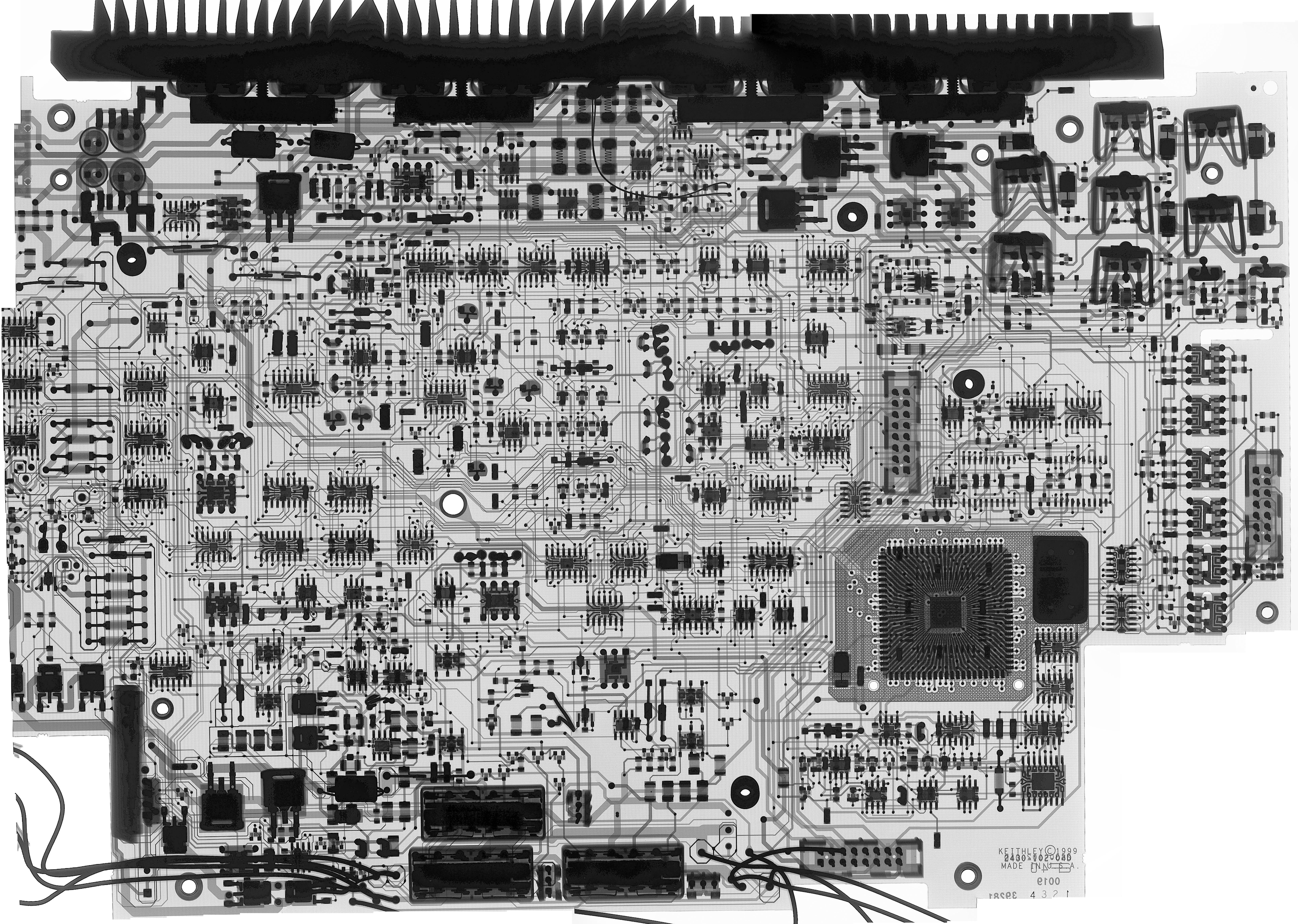
Image : 2425 Analog board, Rev.D, transparent view
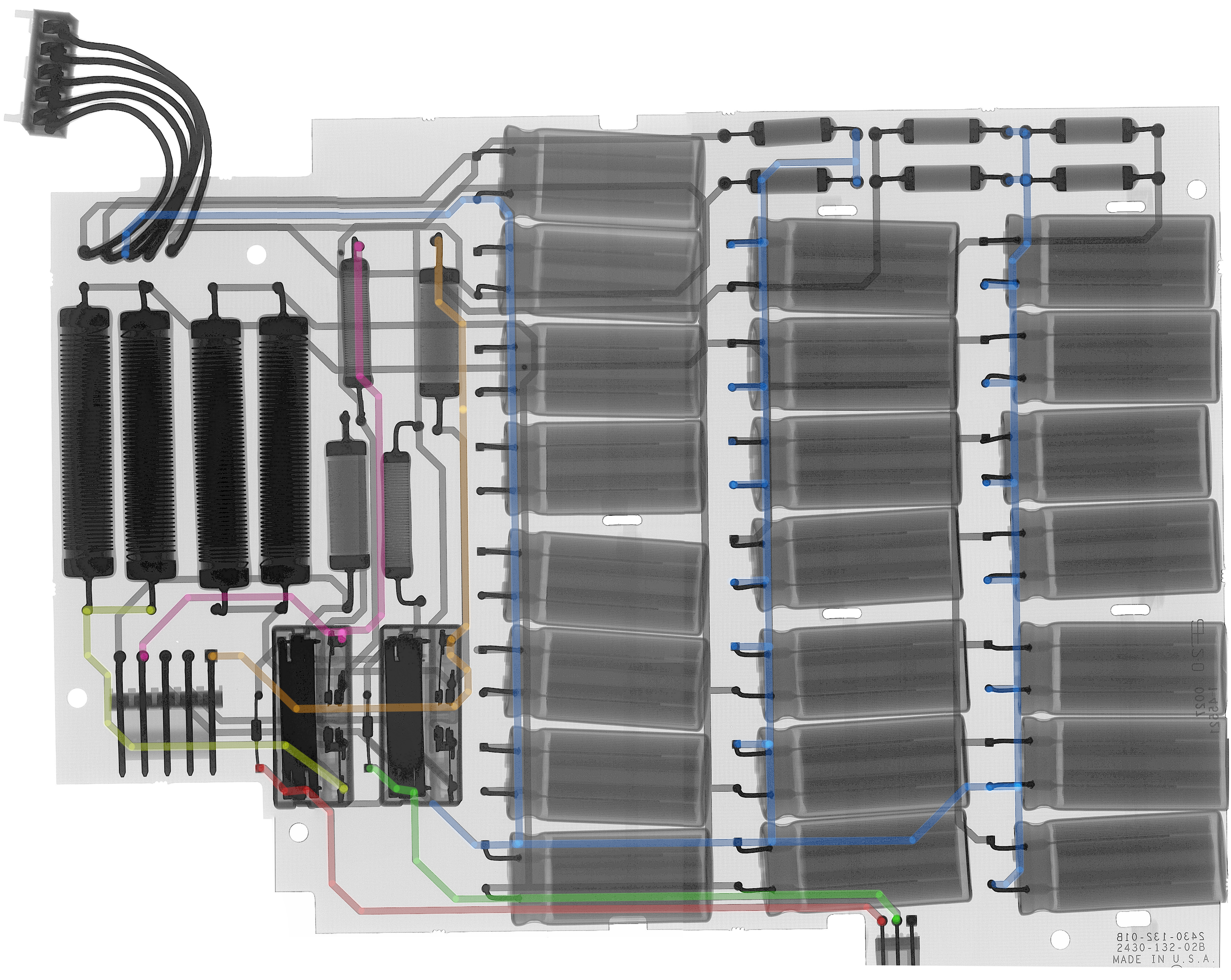
Image : 2425 Capcitor analog power board, Rev.B, transparent view
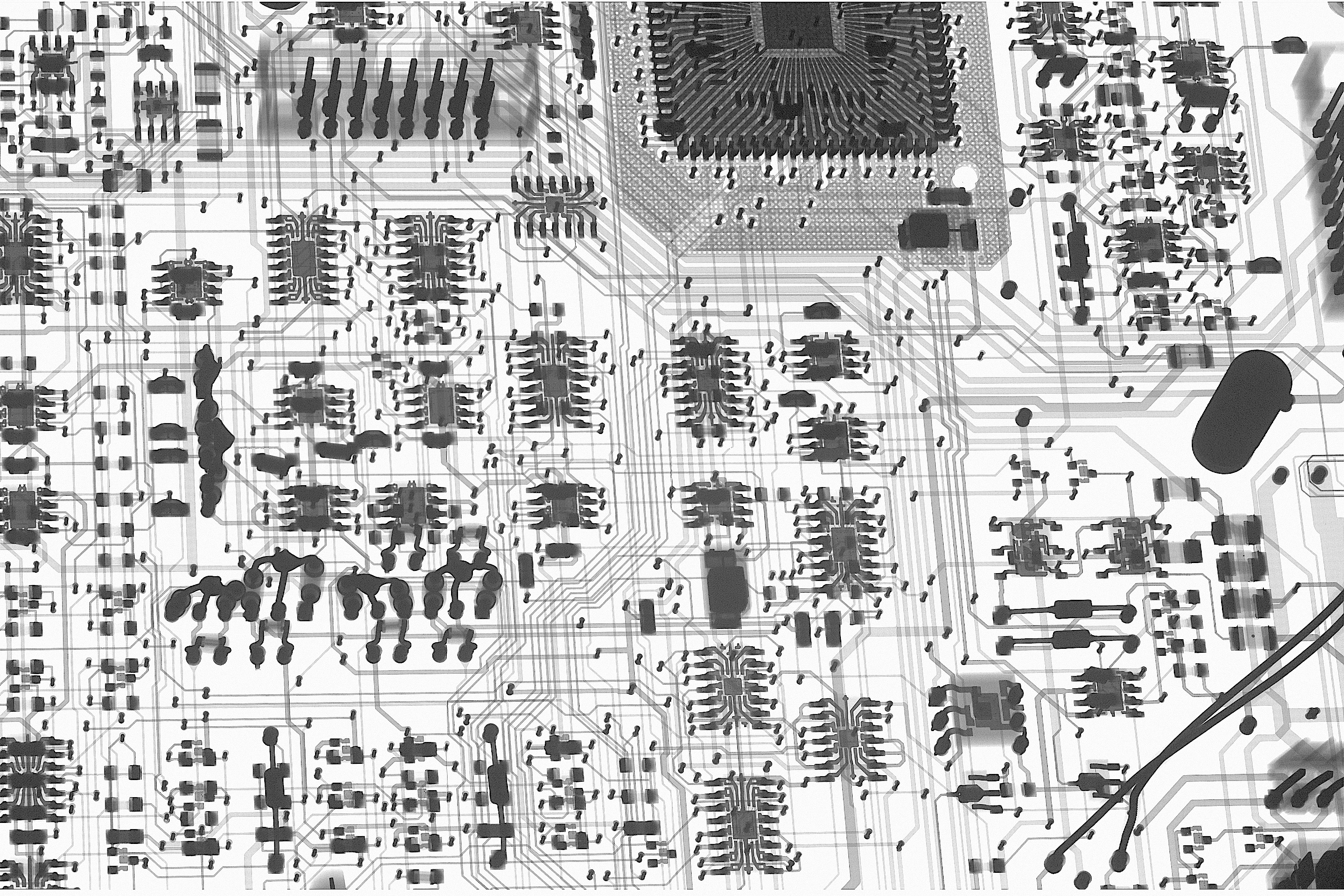
Image : 2425 Analog board, Rev.D, DAC core section angled, transparent view
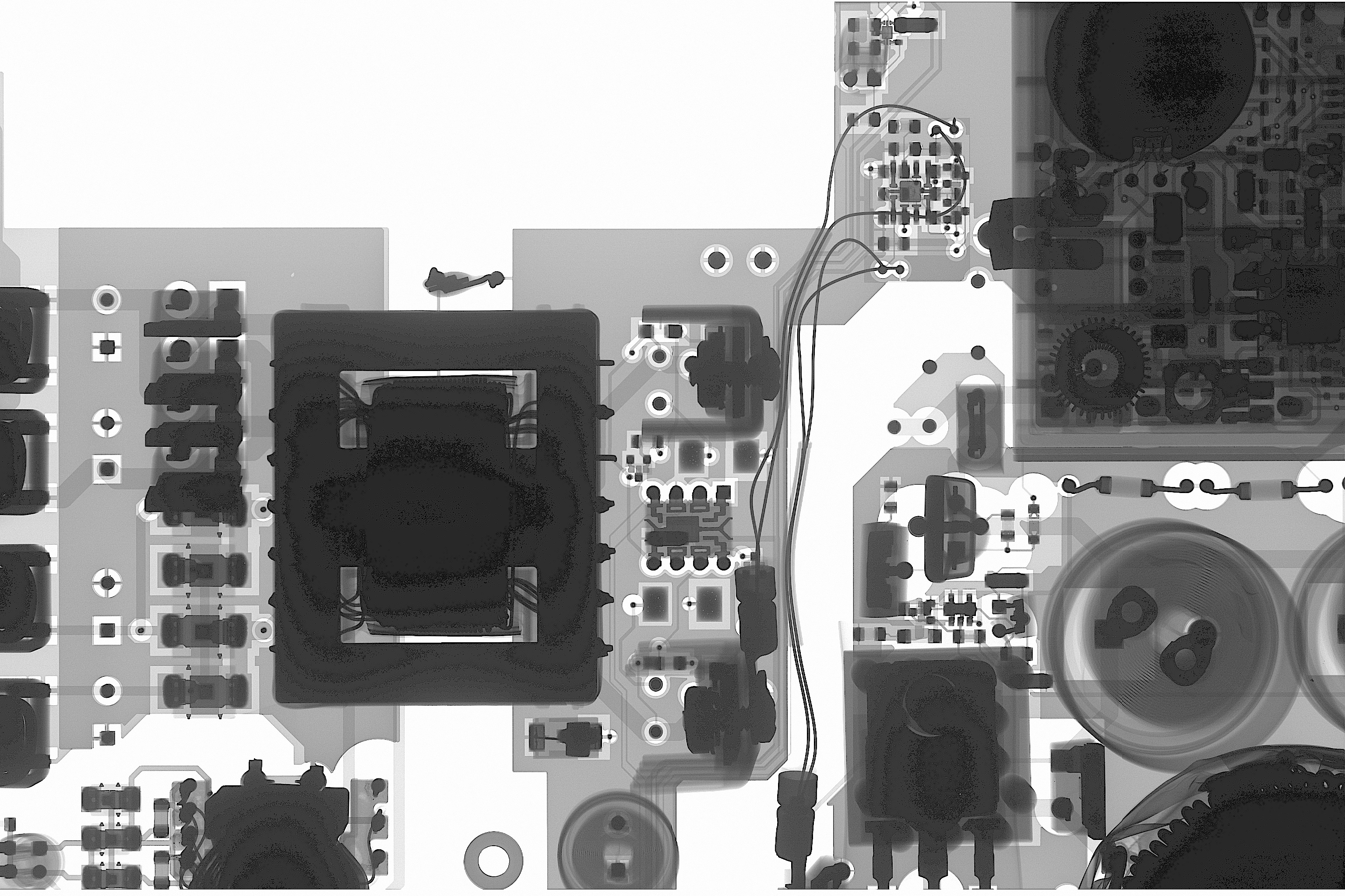
Image : 2425 Digital board, Rev.F, DC-DC section
Issue with wrong current reporting/constants found a solution on a firmware level. I’ve updated firmware to build C33 on this instrument and after writing down correct board revisions to match the actual hardware (Rev. D for Analog board and Rev. F for Digital board) SMU operated as expected and passed full self-test in many continous loops. Now since original calibration constants are gone, we need to perform full adjustment and calibration, on every range and function.
For adjustment and calibration we need HP/Agilent/Keysight 3458A 8½-digit DMM and 1 Ω high-power shunt capable to operate at current 3 A. I’ve automated testing and adjustment with Python script:
Calibration/adjustment application for Model 2425 w/Raspberry Pi
Constants readout from this SMU before running a script (with 100mA, 1A, 3A current ranges adjusted manually during tests):
0.2 DCV Range, SENS:DATA? = -1.240000E+00,+0.000000E+00,-1.240000E+00,+0.000000E+00
0.2 DCV Range, SOUR:DATA? = +2.978864E+05,+5.000000E+02,-2.978864E+05,+5.000000E+02
2.0 DCV Range, SENS:DATA? = -1.240000E+00,+0.000000E+00,-1.240000E+00,+0.000000E+00
2.0 DCV Range, SOUR:DATA? = +2.978864E+04,+5.000000E+02,-2.978864E+04,+5.000000E+02
20.0 DCV Range, SENS:DATA? = -1.240000E+01,+0.000000E+00,-1.240000E+01,+0.000000E+00
20.0 DCV Range, SOUR:DATA? = +2.978864E+03,+5.000000E+02,-2.978864E+03,+5.000000E+02
100.0 DCV Range, SENS:DATA? = -6.200000E+01,+0.000000E+00,-6.200000E+01,+0.000000E+00
100.0 DCV Range, SOUR:DATA? = +5.957727E+02,+5.000000E+02,-5.957727E+02,+5.000000E+02
1.0e-05 DCI Range, SENS:DATA? = -6.200000E-06,+0.000000E+00,-6.200000E-06,+0.000000E+00
1.0e-05 DCI Range, SOUR:DATA? = +5.957727E+09,+5.000000E+02,-5.957727E+09,+5.000000E+02
1.0e-04 DCI Range, SENS:DATA? = -6.200000E-05,+0.000000E+00,-6.200000E-05,+0.000000E+00
1.0e-04 DCI Range, SOUR:DATA? = +5.957727E+08,+5.000000E+02,-5.957727E+08,+5.000000E+02
1.0e-03 DCI Range, SENS:DATA? = -6.200000E-04,+0.000000E+00,-6.200000E-04,+0.000000E+00
1.0e-03 DCI Range, SOUR:DATA? = +5.957727E+07,+5.000000E+02,-5.957727E+07,+5.000000E+02
1.0e-02 DCI Range, SENS:DATA? = -6.200000E-03,+0.000000E+00,-6.200000E-03,+0.000000E+00
1.0e-02 DCI Range, SOUR:DATA? = +5.957727E+06,+5.000000E+02,-5.957727E+06,+5.000000E+02
1.0e-01 DCI Range, SENS:DATA? = -6.262036E-02,-2.072752E-05,-6.263909E-02,+0.000000E+00
1.0e-01 DCI Range, SOUR:DATA? = +6.067707E+05,+2.311992E+02,-6.062150E+05,+2.072031E+02
1.0e+00 DCI Range, SENS:DATA? = -1.252005E+00,-7.553697E-04,-1.253959E+00,+0.000000E+00
1.0e+00 DCI Range, SOUR:DATA? = +6.084252E+04,+6.946953E+02,-6.071851E+04,+6.032227E+02
3.0e+00 DCI Range, SENS:DATA? = -1.272221E+01,-1.325130E-03,-1.252129E+01,+0.000000E+00
3.0e+00 DCI Range, SOUR:DATA? = +5.984797E+03,+6.568027E+02,-6.076977E+03,+6.537480E+02
This adjustment/calibration script runs about 30 minutes and requires few cable swaps by operator, according to prompts on a screen. It was tested to run on Python 3.9.x environment in both Windows and Linux systems, with Keysight E5810A GPIB gateway for interfacing instruments.
For testing 3 A range on Keithley 2425 I’ve built a transfer high-power shunt using VPG VHP-4 1 Ω resistor element in 4-wire TO-3 package, mounted on a large 130 × 130 mm heatsink and actively cooled with large 120×120×38 mm DC fan (Delta AFB1224HE), powered from separate E3644A power supply. This shunt was calibrated with Measurements International 6010B 9½-digit DCC resistance bridge relative to my primary resistance references. Keithley calls out for characterization ±300 µΩ/Ω for this shunt, so it was not hard to achieve with proper testing. Testing at a nominal current of 3 A was done in polarity reversal delta mode with Fluke calibrator and 3458A as digitizer. This is common way of testing higher current shunts. Alternative way could be using DMM with high current 10/20A range such as Fluke 8508A/8558A/8588A, but I didn’t have one available during this worklog.
Adjustment procedure was completed on June 4, 2025 and post-adjustment calibration returned excellent agreement to stable and known good HP 3458A, last calibrated June 12, 2024. Calibration constants and calibration performance test results for this Model 2425 are summarized in a table below.
Post-cal K2425 Calibration data
0.2 DCV Range, SENS:DATA? = -1.252659E+00,-1.549423E-04,-1.252674E+00,+0.000000E+00
0.2 DCV Range, SOUR:DATA? = +3.034225E+05,+1.036145E+03,-3.032788E+05,+8.975977E+02
2.0 DCV Range, SENS:DATA? = -1.252612E+00,-1.587868E-04,-1.252734E+00,+0.000000E+00
2.0 DCV Range, SOUR:DATA? = +3.031176E+04,+2.210703E+02,-3.029739E+04,+2.070859E+02
20.0 DCV Range, SENS:DATA? = -1.253286E+01,-7.762909E-04,-1.253408E+01,+0.000000E+00
20.0 DCV Range, SOUR:DATA? = +3.029551E+03,+2.186289E+02,-3.028112E+03,+2.095273E+02
100.0 DCV Range, SENS:DATA? = -6.261010E+01,-3.509521E-03,-6.261620E+01,+0.000000E+00
100.0 DCV Range, SOUR:DATA? = +6.064352E+02,+2.183477E+02,-6.061489E+02,+2.097578E+02
1.0e-05 DCI Range, SENS:DATA? = -6.249068E-06,-2.538400E-09,-6.249725E-06,+0.000000E+00
1.0e-05 DCI Range, SOUR:DATA? = +6.080274E+09,+2.338906E+02,-6.075722E+09,+1.990547E+02
1.0e-04 DCI Range, SENS:DATA? = -6.267643E-05,-2.513116E-08,-6.268286E-05,+0.000000E+00
1.0e-04 DCI Range, SOUR:DATA? = +6.062262E+08,+2.337148E+02,-6.057722E+08,+1.992461E+02
1.0e-03 DCI Range, SENS:DATA? = -6.233596E-04,-2.491288E-07,-6.234226E-04,+0.000000E+00
1.0e-03 DCI Range, SOUR:DATA? = +6.095372E+07,+2.336953E+02,-6.090821E+07,+1.992383E+02
1.0e-02 DCI Range, SENS:DATA? = -6.265942E-03,-2.541579E-06,-6.266550E-03,+0.000000E+00
1.0e-02 DCI Range, SOUR:DATA? = +6.063908E+06,+2.339375E+02,-6.059386E+06,+1.990859E+02
1.0e-01 DCI Range, SENS:DATA? = -6.260510E-02,-2.541393E-05,-6.261136E-02,+0.000000E+00
1.0e-01 DCI Range, SOUR:DATA? = +6.069139E+05,+2.340625E+02,-6.064566E+05,+1.992422E+02
1.0e+00 DCI Range, SENS:DATA? = -1.252485E+00,-4.993677E-04,-1.252552E+00,+0.000000E+00
1.0e+00 DCI Range, SOUR:DATA? = +6.082573E+04,+6.775781E+02,-6.077809E+04,+6.093750E+02
3.0e+00 DCI Range, SENS:DATA? = -1.259972E+01,-5.086899E-03,-1.260149E+01,+0.000000E+00
3.0e+00 DCI Range, SOUR:DATA? = +6.046173E+03,+6.778574E+02,-6.040767E+03,+6.087285E+02
Calibration verification results all well within Keithley 2425 specifications, even at a fraction of the lowest range for both voltage and current functions.
| Test point | Sourced signal from SMU | Measured median 16 values | Statistics |
|---|---|---|---|
| DCV Verification step 00 | 0 V | 5.02 µVDC | |
| DCV Verification step 01 | -0.002 V | -0.0019942051 VDC | deviation -2897.4 ppm |
| DCV Verification step 02 | 0.002 V | 0.00199972102 VDC | deviation -139.5 ppm |
| DCV Verification step 03 | -0.02 V | -0.019997525 VDC | deviation -123.8 ppm |
| DCV Verification step 04 | 0.02 V | 0.0200036341 VDC | deviation 181.7 ppm |
| DCV Verification step 05 | -0.2 V | -0.199991042 VDC | deviation -44.8 ppm |
| DCV Verification step 06 | 0.2 V | 0.200000981 VDC | deviation 4.9 ppm |
| DCV Verification step 07 | 0 V | 4.09 µVDC | |
| DCV Verification step 08 | -1 V | -1.00001764 VDC | deviation 17.6 ppm |
| DCV Verification step 09 | 1 V | 1.00002502 VDC | deviation 25.0 ppm |
| DCV Verification step 10 | -2 V | -1.99991314 VDC | deviation -43.4 ppm |
| DCV Verification step 11 | 2 V | 1.9999451 VDC | deviation -27.5 ppm |
| DCV Verification step 12 | 0 V | 9.11 µVDC | |
| DCV Verification step 13 | -10 V | -9.99998327 VDC | deviation -1.7 ppm |
| DCV Verification step 14 | 10 V | 10.0005399 VDC | deviation 54.0 ppm |
| DCV Verification step 15 | -15 V | -14.9996973 VDC | deviation -20.2 ppm |
| DCV Verification step 16 | 15 V | 14.9999041 VDC | deviation -6.4 ppm |
| DCV Verification step 17 | -20 V | -19.9989751 VDC | deviation -51.2 ppm |
| DCV Verification step 18 | 20 V | 19.9994093 VDC | deviation -29.5 ppm |
| DCV Verification step 19 | 0 V | -25.95 µVDC | |
| DCV Verification step 20 | -100V | -99.9950336 VDC | deviation -49.7 ppm |
| DCV Verification step 21 | 100 V | 99.9964022 VDC | deviation -36.0 ppm |
| DCV Verification step 22 | 0 V | 89.41 µVDC | |
| DCI Verification step | -1 uA | -9.9990187e-07 ADC | deviation -98.1 ppm |
| DCI Verification step | 1 uA | 1.00002302e-06 ADC | deviation 23.0 ppm |
| DCI Verification step | -10 uA | -9.99992982e-06 ADC | deviation -7.0 ppm |
| DCI Verification step | 10 uA | 9.9999164e-06 ADC | deviation -8.4 ppm |
| DCI Verification step | -100 uA | -9.99991845e-05 ADC | deviation -8.2 ppm |
| DCI Verification step | 100 uA | 9.99997854e-05 ADC | deviation -2.1 ppm |
| DCI Verification step | -1 mA | -0.00100000139 ADC | deviation 1.4 ppm |
| DCI Verification step | 1 mA | 0.00100000758 ADC | deviation 7.6 ppm |
| DCI Verification step | -4 mA | -0.0039999414 ADC | deviation -14.7 ppm |
| DCI Verification step | 4 mA | 0.00399990685 ADC | deviation -23.3 ppm |
| DCI Verification step | -10 mA | -0.00999990951 ADC | deviation -9.0 ppm |
| DCI Verification step | 10 mA | 0.00999999454 ADC | deviation -0.5 ppm |
| DCI Verification step | -20 mA | -0.0200020688 ADC | deviation 103.4 ppm |
| DCI Verification step | 20 mA | 0.0200023629 ADC | deviation 118.1 ppm |
| DCI Verification step | -100 mA | -0.050002907 ADC | deviation 58.1 ppm |
| DCI Verification step | 100 mA | 0.0500014299 ADC | deviation 28.6 ppm |
| DCI Verification step | -200 mA | -0.0999986263 ADC | deviation -13.7 ppm |
| DCI Verification step | 200 mA | 0.0999985369 ADC | deviation -14.6 ppm |
| DCI Verification step | -1 A | -0.999984517 ADC | deviation -15.5 ppm |
| DCI Verification step | 1 A | 1.00002653 ADC | deviation 26.5 ppm |
| DCI Verification step | Zero 1 A | -13.343 µADC | |
| DCI Verification step | -3 A | -2.99980468 ADC | deviation -65.1 ppm |
| DCI Verification step | 3 A | 2.99998876 ADC | deviation -3.7 ppm |
| DCI Verification step | Zero 3 A | -296.99 µADC |
These data points are taken directly from output log by script. With this repair of this instrument is considered successful and complete.
A look inside destroyed Model 2400LV
Sadly even with decades of repair experience some instruments are just not economical to repair. One of these come across my bench this time as well, Model 2400LV. LV means low voltage version of standard 2400. This was achieved by defeaturing top 200 V range. Perhaps it was a solution for specific customer or for marketing purposes to promote lower cost SourceMeter instrument. These 2400LV are otherwise identical to normal 2400 both in specifications and functionality. I was curious to see internal design of 2400LV, to determine if all the hardware same as normal box or if 2400LV really has cheaper/changed circuitry as well.
Same board with some light behind it to reveal some inner layout and routing.
Here’s standard Model 2400 with analog board of same Rev F type.
On the back we can see lot of surface mount capacitors and resistors, supporting all the active components in this instrument.
Same photograph with a light behind.
I don’t know the full story behind this unfortunate SourceMeter ‘repair,’ but it’s not hard to guess what might have happened. Perhaps a previous owner of this 2400LV followed one of those popular online tips for reviving electronics – the infamous reflow trick. Just grab a hot air station, crank it up to 700 freedom units, drown the board in flux, and blast heat over the delicate Keithley 2400LV chips until something starts to sizzle. That should reflow all the pins… right?”
Now that approach may sometimes work on heavy copper computer motherboard or power supply repair where parasitic leakage currents and sensitive parts are not a common occurrence. But this is a very low copper mass 30 year old four layer PCB that is very easy to overheat. In these photos, we can clearly see the telltale signs of thermal damage: scorched areas, flux residue, and accumulated grime from repairman handyworks.
If that was not enough to cook the board once, same was done many times to different areas of this poor PCBA. Truly, leave no stone untouched. Sadly this board isn’t very useful even as donor for components and chips, as they are extremely dirty and probably would open infinite pandora boxes if used anywhere in a good instrumentm
But back to our main topic, the difference between 2400LV and 2400? To be honest I don’t see any physical hardware discrepancy between the two. This 200V range deactivation must be done on a firmware level, unless there is some sneaky SMT resistor to strap the brains of the instrument about voltage limit. Below you can find glorious hundred megapixel photographs of both digital and analog board sides if you are willing to compare each part and areas?
Today Tektronix/Keithley has a different name for such lower cost SourceMeter product, Model 2401 and I believe these old 2400LV are long obsoleted today.
Bonus photos, Keithley 6430 sub-femtoamp remote SMU
Since we are at all things SourceMeter, it would be a shame to skip a step on king of SourceMeter, Model 6430. This special instrument is a versatile and powerful instrument for very low currents, at picoampere levels and below. Model 6430 is a modified 2400 with added support of a small external Preamp module. When 6430 operated without preamp attached it’s ranges and functions are almost identical to standard Keithley 2400 with only rear output available. Only difference in this case would be missing 1 A current range. But it would be a waste to use 6430 as simple 2400, and when a matching 6430 preamp is attached current ranges below 1 µA become available. This also involves compliance limits and such combination of mainframe+preamp turns the setup into a full-featured SourceMeter with lowest full-scale current range at 1.0 pA (10-12) with 6½-digits of measurement resolution.
I’ve updated my Keithley 6430 original firmware C18 into a newer firmware C30. Latest builds of standard 2400 firmware don’t have 6430 support anymore.

And here’s a photograph of analog board used in my 6430 mainframe.

I have taken apart 6430 preamp head and compared to very similar Keithley 4200 SCS head in older article here. These preamp modules are packed with fA-grade amplifiers, high value film resistor networks, proper triaxial connectors and PCB slotted and milled with isolation gaps like a swiss cheese.
Firmware images and dumps
Here are some firmware dumps for Keithley 2400 series SMUs.
Supported instruments:
- Keithley Model 2400
- Keithley Model 2410
- Keithley Model 2420
- Keithley Model 2425
- Keithley Model 2426 (special version of 2425 with 60V limit instead of 100V)
- Keithley Model 2430
- Keithley Model 2440
- Keithley Model 2400-C
- Keithley Model 2410-C
- Keithley Model 2420-C
- Keithley Model 2425-C
- Keithley Model 2430-C
- Keithley Model 2440-C
| Firmware version | Combined binary | ODD ROM | EVEN ROM | Original SREC + Release notes |
|---|---|---|---|---|
| Model 24XX C06 Version 51.1, Dec 16 14:52:35 EST 1996 | 24XX Full binary | SREC | ||
| Model 24XX C10 Version 62.1, Jun 4 13:53:13 EDT 1997 | 24XX Full binary | 2400-803-C10 ODD ROM | 2400-804-C10 EVEN ROM | |
| Model 24XX C30 Version 192.1, Mar 17 09:28:23 EST 2006 | 24XX Full binary | SREC ZIP | ||
| Model 24XX C32 Version 199.1, Oct 4 14:19:20 EDT 2010 | 24XX Full binary | 2400-803-C32 ODD ROM | 2400-804-C32 EVEN ROM | SREC ZIP |
| Model 24XX C33 Version 201.1, Mar 31 09:31:47 EST 2015 | 24XX Full binary | 2400-803-C33 ODD ROM | 2400-804-C33 EVEN ROM | SREC ZIP |
| Model 24XX C34 Version 199.1, Oct 4 14:19:20 EDT 2010 | 24XX Full binary | 2400-803-C34 ODD ROM | 2400-804-C34 EVEN ROM | SREC ZIP |
Keithley distributes firmware upgrades in original Motorola S-Record format, so you might want to use SREC2BIN tool if you’d like to get a binary. S-Record website also have other handy tools like BIN2SREC and BINSPLIT to cut one binary into 16/32 bit wide uses for multiple chips programming.
Version C33 fixes the issue of powering up with a low line-voltage (90 volts in Japan) for models 2420, 2425, 2430, 2440. Upgrading to this version of firmware will add a 5-second delay to power-up for all models running it. Version C34 adds a fix for some special cases guarding issues.
Keep in mind that newer firmware builds with “B” or “D” index in build version are NOT compatible with old instrument running “C**” firmware. There is also limited 2401 SMU that has own B-tagged firmware and not compatible with traditional 24XX series.
Also here’s Python app to generate EVEN+ODD ROMs from full little-endian binary file, just in case someone need it.
# xDevs.com Firmware combine tool
# https://xdevs.com/fix/kei2400

import os

with open('2400c32.bin','rb') as a:
    with open('2400-804-C32.bin','wb') as bf, open('2400-803-C32.bin','wb') as cf:
            for cnt in range(0, 262144):
                bf.write ("%s" % a.read(1) )
                cf.write ("%s" % a.read(1) )
It takes input binary and prints it into two files output. Opposite application to combine split files into single little-endian binary available as well.
Performance benchmarks after repairs
Automation software for calibration/adjustment purposes
Python calibration application to download
Calibration/adjustment application for Model 2400 w/Raspberry Pi
Calibration/adjustment application for Model 2410 w/Raspberry Pi (Python) for vxi11 inteface library
Helper script to setup Python environment on RPi for 2410 script
Download this Python app into folder on your Pi, for example using wget:
wget https://xdevs.com/doc/Keithley/2400/calsw/cal2400.py
Now make sure both instruments connected to GPIB and USB-GPIB dongle is properly working.
Noise measurements comparison
Non-linearity measurement comparison
Python script for INL sweeping
Conclusion and summary
With this article I am happy to report that more of these very capable instruments from Tektronix/Keithley are now saved from filling up hazmat dumpsters and returned to full service duty in the lab. I’d like to also recognize Tektronix’s decision of keeping original Keithley 2400 line of SMUs in current production, as many customers may not need the latest and shiniest gear to get the job done. It is good to know that products like these could actually be maintained and supported even 30 years after their initial release. There are not many modern instruments that can demonstrate such track record and somehow I feel that latest software-based gear may not be able to stay alive by year 2055.
Projects like this are born from passion and a desire to share how things work. Education is the foundation of a healthy society - especially important in today's volatile world. xDevs began as a personal project notepad in Kherson, Ukraine back in 2008 and has grown with support of passionate readers just like you. There are no (and never will be) any ads, sponsors or shareholders behind xDevs.com, just a commitment to inspire and help learning. If you are in a position to help others like us, please consider supporting xDevs.com’s home-country Ukraine in its defense of freedom to speak, freedom to live in peace and freedom to choose their way. You can use official site to support Ukraine – United24 or Help99. Every cent counts.
Modified: March 19, 2026, 9:44 p.m.