- Introduction
- Disclaimer
- Few words about the ‘as received’ condition, exterior
- Manuals and datasheets
- Teardown, cleaning and repairs
- Performance tests for 34420A
- Modifications and experiments
- Summary and conclusion
Introduction and motivation for this article
This is work in progress project, updates will be posted frequently.
xDevs.com finally aquired own borked HP 34420A nanovoltmeter. Previous article about HP34420A touched up a little bit about repair for our friend Steve. Now it’s time we dig deeper with our very own 34420A.
Thanks to my friend David, I already had nanovoltmeter from Keithley – Model 2182A, that is in use with DC voltage zener bank in series-opposition measurements and 10V zener standards calibrations. But since that 2182A is permanently tied in the bank I wanted another nanovoltmeter for sensitive measurements and various lab projects. This is the gap that this HP34420A will be taking. Also this means no limitations for the experiments or dangerous ideas this time.
Image 1: HP 34420A 7½-digit nanovolt/microohm-meter
Model 34420A is also quite useful tool to calibrate conventional voltage standards such as solid-state zener-based 10 V sources such as Fluke 732 or Datron 4910. Overall HP 34420A is quite interesting instrument. It is essentially a refined HP 34401A but with good low-noise front end amplifier providing additional 1 mV, 10 mV and 100 mV DC ranges. These front-end improvements together with refined ADC operation were utilized to push resolution of 34420A to 7½ digits.
Typical shrouded banana jack input connectors on 34420A are replaced instead with more serious (and expensive) LEMO EVP.1S.304 sealed bare-copper connector to provide four contacts for dual channel operation. 34420A is a current product and still being manufactured at MY and SG sites pretty much unchanged by the Keysight Technologies. Brand new nanovoltmeter would set you back at least for $7760 USD. Standard calibration for 34420A is about $1730 USD. Only alternative instrument in this class is Tektronix/Keithley 2182A nanovoltmeter for similar price at $6160 USD and without resistance measurement functionality. These instruments are quite popular and go for few k$ even used on secondary market, especially if calibration is available.
| Range | 2-minute RMS noise | 2-minute peak-peak noise | 24-hour peak-peak noise |
|---|---|---|---|
| 1 mV | 1.3 nVrms | 8 nVpp | 12 nVpp |
| 10 mV | 1.5 nVrms | 10 nVpp | 14 nVpp |
| 100 mV | 10 nVrms | 65 nVpp | 80 nVpp |
| 1 V | 100 nVrms | 650 nVpp | 800 nVpp |
| 10 V | 450 nVrms | 3 μVpp | 3.7 μVpp |
| 100 V | 11 μVrms | 75 μVpp | 90 μVpp |
Table 1. 34420A Observational period DC voltage noise
| Source resistance | Noise | Analog filter | Digital filter |
|---|---|---|---|
| 0 Ω | 1.3 nVrms | Off | Med |
| 100 Ω | 1.7 nVrms | Off | Med |
| 1 kΩ | 4 nVrms | Off | Med |
| 10 kΩ | 13 nVrms | Off | Med |
| 100 kΩ | 41 nVrms | On | Med |
| 1 MΩ | 90 nVrms | On | Slow |
Table 2. 34420A DC voltage noise vs source resistance relationship
A/D for this nanovoltmeter is specified at 0.8 ppm of the reading + 0.5 ppm of the range. 34420A does not have AC voltage or DC/AC current measurement funtions but keeps resistance measurement functionality using all four input terminals. This resistance function is a significant feature that enables use of 34420A in applications such as automated leakage measurements for quantum voltage metrology in PJVS systems like NIST SRI 6000. Leakage measurements and evaluation is very important in this application as parasitic currents would essentially propagate into output voltage error at the PJVS terminals. 34420A also has pretty good thermometry functionality, supporting various SPRT, thermistors and thermocouples.
Even common accessory for 34420A such as calibration short for zero verification and four-wire low thermal cable are easily over $400 if you buy original new. Original Keysight Technologies part-numbers for the interconnect and shorting plug are listed in the Table 3 below. Instrument like 34420A is a rather niche tool for the applications that normal DMM wouldn’t be a good fit.
| Keysight P/N | Description | Pricing (October 2024) |
|---|---|---|
| 34102A | Low-thermal LEMO input cable 4-wire with bare copper spade lugs | $317 USD |
| 34103A | Low-thermal LEMO shorting cable | $253 USD |
| 34104A | Low-thermal LEMO input connector (FVN.1S.902.CLY) | $193 USD |
| 34131A | Transit case for half-width 2U instruments | $554 USD |
| 34161A | Accessory pouch | $58 USD |
| 34190A | Rackmount kit for single instrument in the rack | $89 USD |
| 34191A | Rackmount kit for dual flange kit mount (2 instruments) | $84 USD |
| 34194A | Rackmount link for mounting two instruments together | $162 USD |
Table 3: Optional accessories for nanovoltmeter
Disclaimer
Redistribution and use of this article or any images or files referenced in it, in source and binary forms, with or without modification, are permitted provided that the following conditions are met:
- Redistribution of article must retain the above copyright notice, this list of conditions, link to this page (https://xdevs.com/fix/hp34420a_u2/) and the following disclaimer.
- Redistribution of files in binary form must reproduce the above copyright notice, this list of conditions, link to this page (https://xdevs.com/fix/hp34420a_u2/), and the following disclaimer in the documentation and/or other materials provided with the distribution, for example Readme file.
All information posted here is hosted just for education purposes and provided AS IS. In no event shall the author, xDevs.com site, or any other 3rd party be liable for any special, direct, indirect, or consequential damages or any damages whatsoever resulting from loss of use, data or profits, whether in an action of contract, negligence or other tortuous action, arising out of or in connection with the use or performance of information published here.
If you willing to contribute or have interesting documentation to share regarding pressure measurements or metrology and electronics in general, you can do so by following these simple instructions.
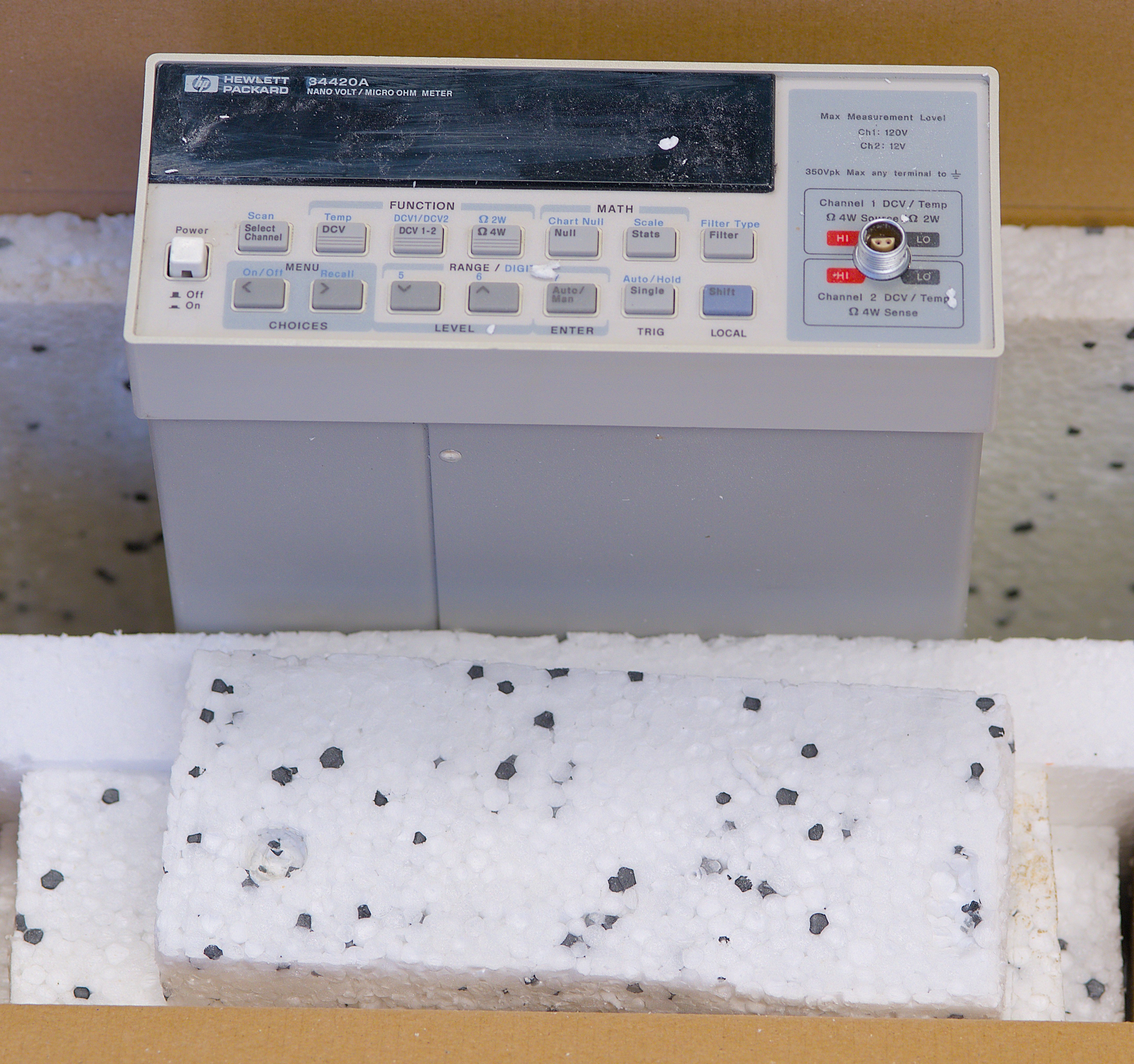
Few words about the “as received” condition, exterior
Instrument was acquired from a closing down lab in Netherlands, sold as parts & repair. Seller feedback was that CH1 was not working, while CH2 input was reading good voltages. It’s little bit unusual since often with nanovoltmeters like HP 34420A or Keithley 2182/2182A it is the second channel that gets blown-up as secondary channel does not have higher 100 V range like the primary. TheSignalPath also made a nice episode about HP 34420A few months ago and his instrument had also broken CH1.
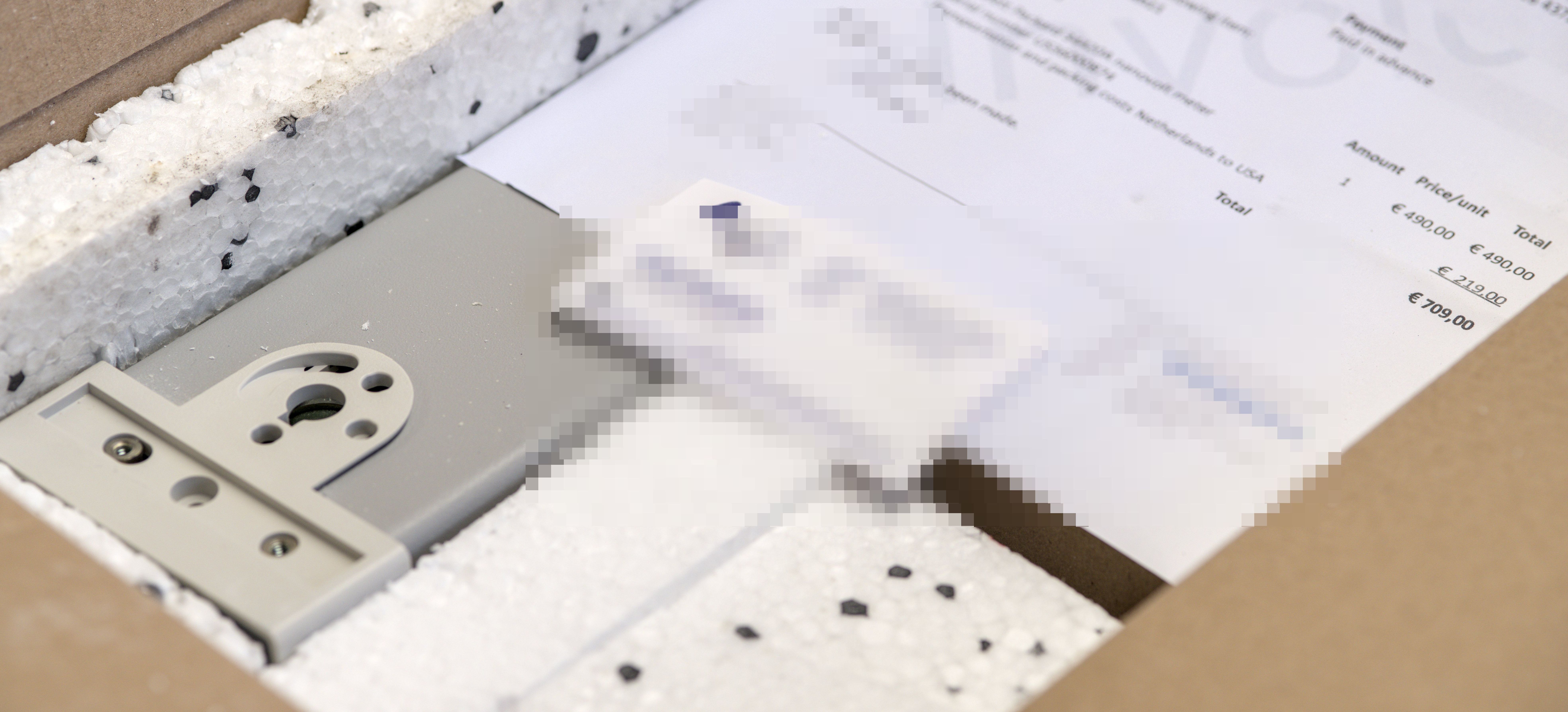
After some time meter arrived in a rough condition slightly rounded box.
With opening we can reveal the second inner box, spaced around with styrofoam pads around. Idea here was to provide some bumper action and isolation of inner box from the shipping handling impacts.
I guess A goes for effort here, which was appreciated at this point. We don’t want to have broken instrument to become more broken mechanically by various transit damages.
Total paid for this 34420A was 490 EUR + pretty expensive 219 EUR for shipping via FedEx. Brings back memories of years living in Taiwan, where shipping anything was relatively pricey. Also it’s funny EUR currency, so I’ve ended up with 820 or so USD total cost, delivered. Let’s see what is inside?
One thing that I prefer to do when shipping sensitive electronics and instruments is to bag them and pad every corner with bubble-wrap. This protects often ESD-sensitive external connectors both mechanically and electrically plus provides some insulation from the outer elements, in case box getting wet. None of that happening here, sadly. Meter just jammed right to the Styrofoam sheets, with zero insulation around it.
That rendered fine Styrofoam dust and particles all over the whole meter. It was deposited everywhere, poor expensive LEMO 1S input connector was jammed right into the styrofoam sheet. You can see the crated connector made in that sheet. Styrofoam is also acting as a nice ESD generator here.
In addition to the fine dust all over we also get a bonus damage – pin 2 (CH1 LO) on the LEMO connector is bent down significantly. I do not think that was caused by the poor packing/shipping or actually previously suffered damage from the previous owner. It is not uncommon to see damage on expensive LEMO ports when inexperienced users try to “test” the meter jamming foreign objects into the fine pins and sockets of this precision machined connector.
Cost of replacing this EVP.1S.304 connector would be about $80 USD plus a need of full re-calibration and adjustment.
Connectors used with nanovoltmeters
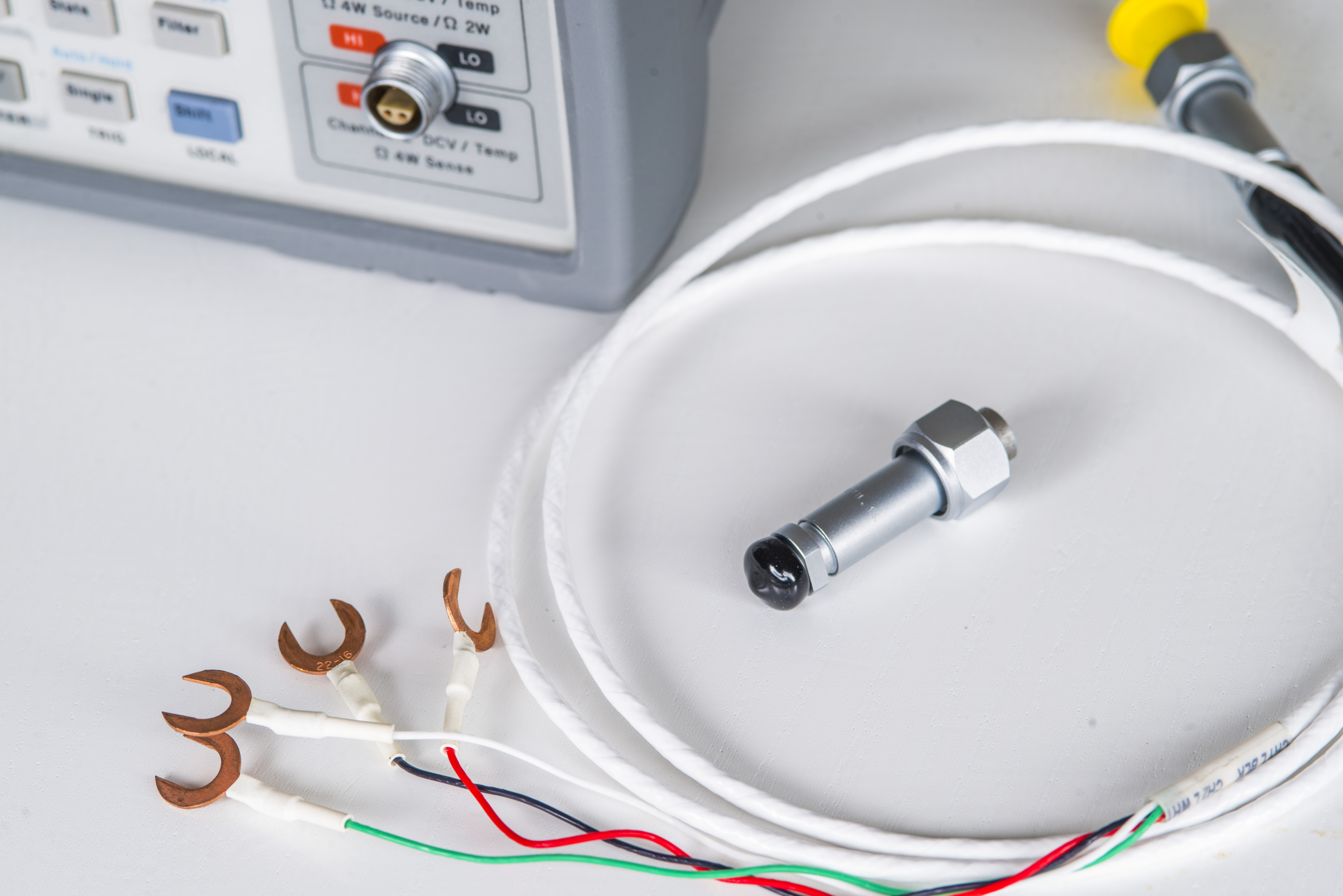
Image 2: Low-thermal cable and short for nanovoltmeter. Same are compatible with Keithley 2182A NVM
Connectors are special version of LEMO 1S.304 with removed gold plating. No plating is important for the lowest possible parasitic thermal EMF. Dissimilar metals, in contact with each other with thermal gradient present produce a small offset voltage. This voltage value depends on junction temperature and is therefore called a thermal EMF. The rate of change of this thermal EMF voltage with temperature is a function of the metals used in combination. The sense of the voltage produced is either positive or negative, depending on which side of the combination is being considered the input. Most, if not all electronic components, even simple resistors, capacitors, diodes have internal intermetallic combinations, and eventually connected to PCB/wire copper conductors as a final junction. Hence, copper is the typical reference metal in thermal EMF figures and analysis. Here are some examples of typical thermoelectric coefficients (also known as Seebeck coefficients) of bi-metal connections with copper.
| Material | Thermoelectric Potential (EMF) | Error magnitude on 1VDC with 5°C ΔT |
|---|---|---|
| Copper-Copper | < 0.2 µV/°C | <1 ppm |
| Copper-Silver | -0.3..+0.03 µV/°C | -1 ppm |
| Copper-Gold | +0.01..+0.2 µV/°C | +1 ppm |
| Copper-Cadmium/Tin | 0.3 µV/°C | 1.5 ppm |
| Copper-Lead/Tin | 1…3 µV/°C | 15 ppm |
| Copper-Zeranin | -1.3 µV/°C | -6.5 ppm |
| Copper-Brass | -1.6 µV/°C | -6.5 ppm |
| Copper-Evanohm | +2.0 µV/°C | +10 ppm |
| Copper-Manganin | -1.7..-3.0 µV/°C | -15 ppm |
| Copper-Aluminum | -4.0 µV/°C | -20 ppm |
| Copper-Nickel | -10..-22.0 µV/°C | -55..-110 ppm |
| Copper-Constantan | +39.7 µV/°C | -195 ppm |
| Copper-Kovar | 40 µV/°C | 200 ppm (0.02%) |
| Copper-Cupron | -45.0 µV/°C | -225 ppm |
| Copper-Silicon | 400 µV/°C | 0.2% |
| Copper-Copper Oxide | 1000 µV/°C | 0.5% |
Table 4: Typical thermal EMF figures with different metal junctions
To minimize thermal offsets use only fresh clean copper wires and spade lugs. Do not solder connections to avoid dissimilar metals on contact area. Soldered connection can make parasitic offsets 1-3µV/°C, which is significant source of error for precision measurements. Make sure surfaces of copper contacts shiny, as copper oxide have very large thermal EMF. If copper oxidized, use soft abrasive pad to clean connections and attach wire immediately. Proper copper-copper connection have typical offset of 0.2 µV/°C or less, while oxidized/tinned connection can be more than 1000 µV/°C.
Instrument like 34420A is sensitive enough to detect such small voltages which would translate to longer settling times and increased measurement uncertainty for small signals. You can indeed buy these connectors and parts directly from LEMO as I did back in 2018 for experiments at xDevs.com. Connector plug for cable side had part-number LEMO FVN.1S.304.CLYC52Z, but now is available as part of LEMO Thermocouple connectors with new part-number FVN.1S.902.CLYC42Z. These connectors sell for about $110 USD per piece. Standard gold-plated version sometimes in stock at Digikey and similar distributors but for low-thermal version be sure to contact LEMO directly.

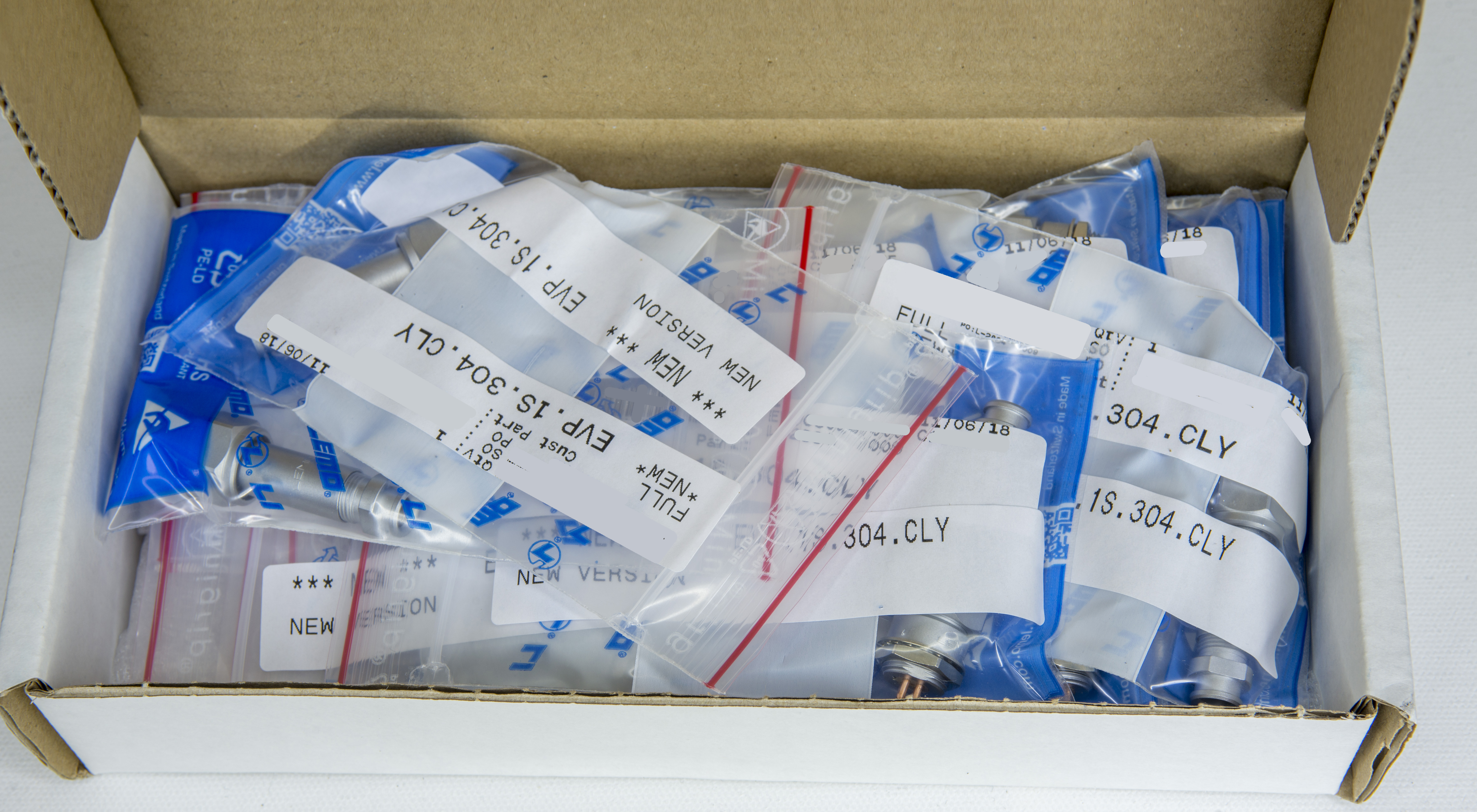
The receptacle (part that is mounted inside of the 34420A itself, or can be used for custom panel interfaces) has part-number EVP.1S.304.CLY. Assembled pair looks like this:

Keep in mind that plastic strain relief is not supplied with the FVN plug and need to be purchased separately from LEMO. Part number for relief is GMA.1B.045.DN for black or GMA.1B.045.DG for grey. Some other colors such as yellow, blue, red, orange, green might also be available for $5 to $7 USD per piece.
It is also important to keep these connectors clean at all times as copper oxide is a terrible conductor and intruduce huge thermal EMF errors.
Do not jam foreign objects, probes or wires into the connector. Copper pins are quite fragile and soft, making them quite easy to bend or damage.
Mayhem with Styrofoam does not end just with the front panel dust. 34420A does not use fan and does not have vent holes, so hopefully at least insides would be clean?
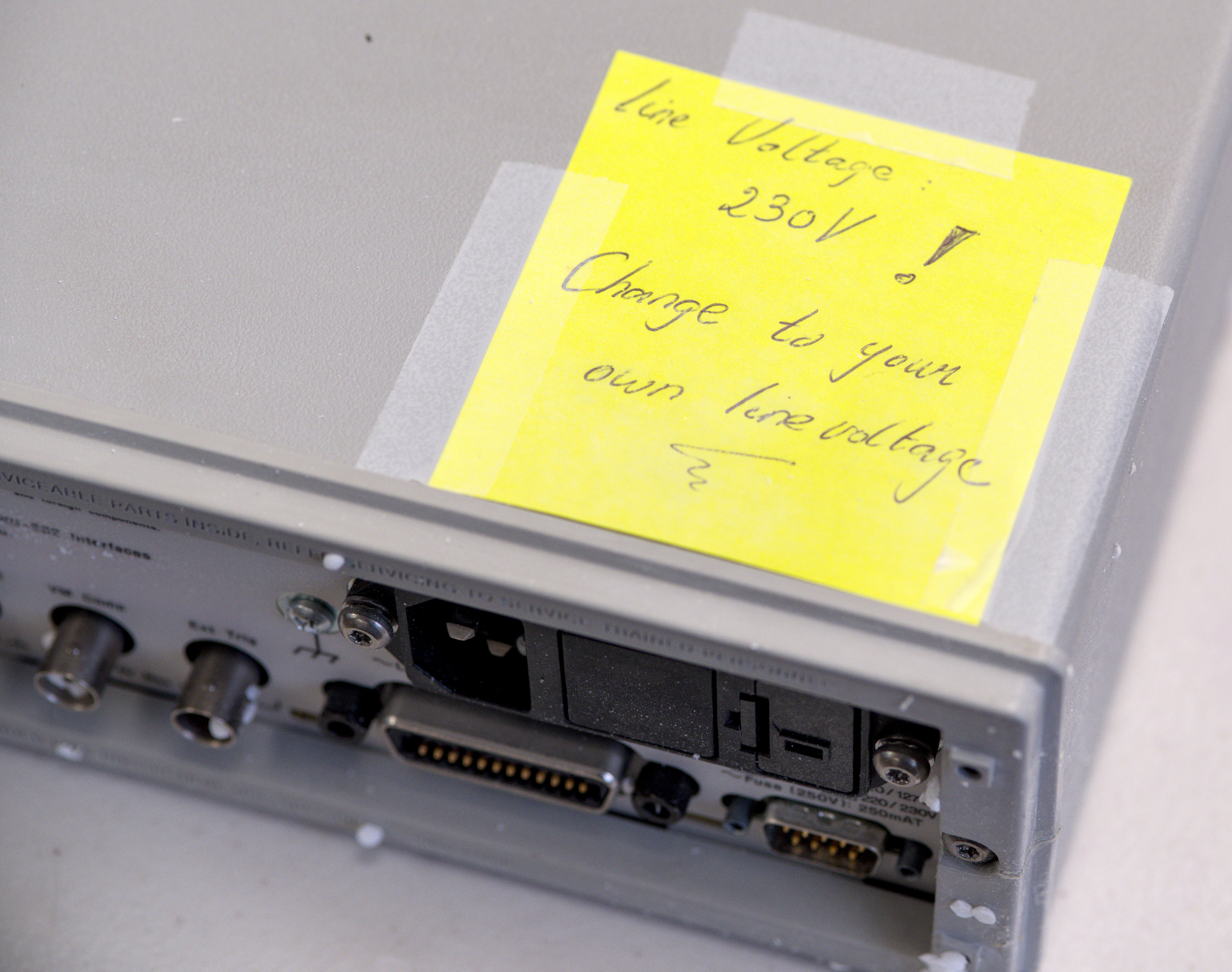
Looking at the back we can “enjoy” the particles jammed in every tight space inside connectors, sockets and receptacles.

But we get a nice warning label about mains voltage level set to 230 V as a bonus. Thanks for that, useful reminder when shipping test equipment internationally. Usually the other way around is the dangerous one, sourcing 120V-preset equipment to the country with 230 V mains voltage.
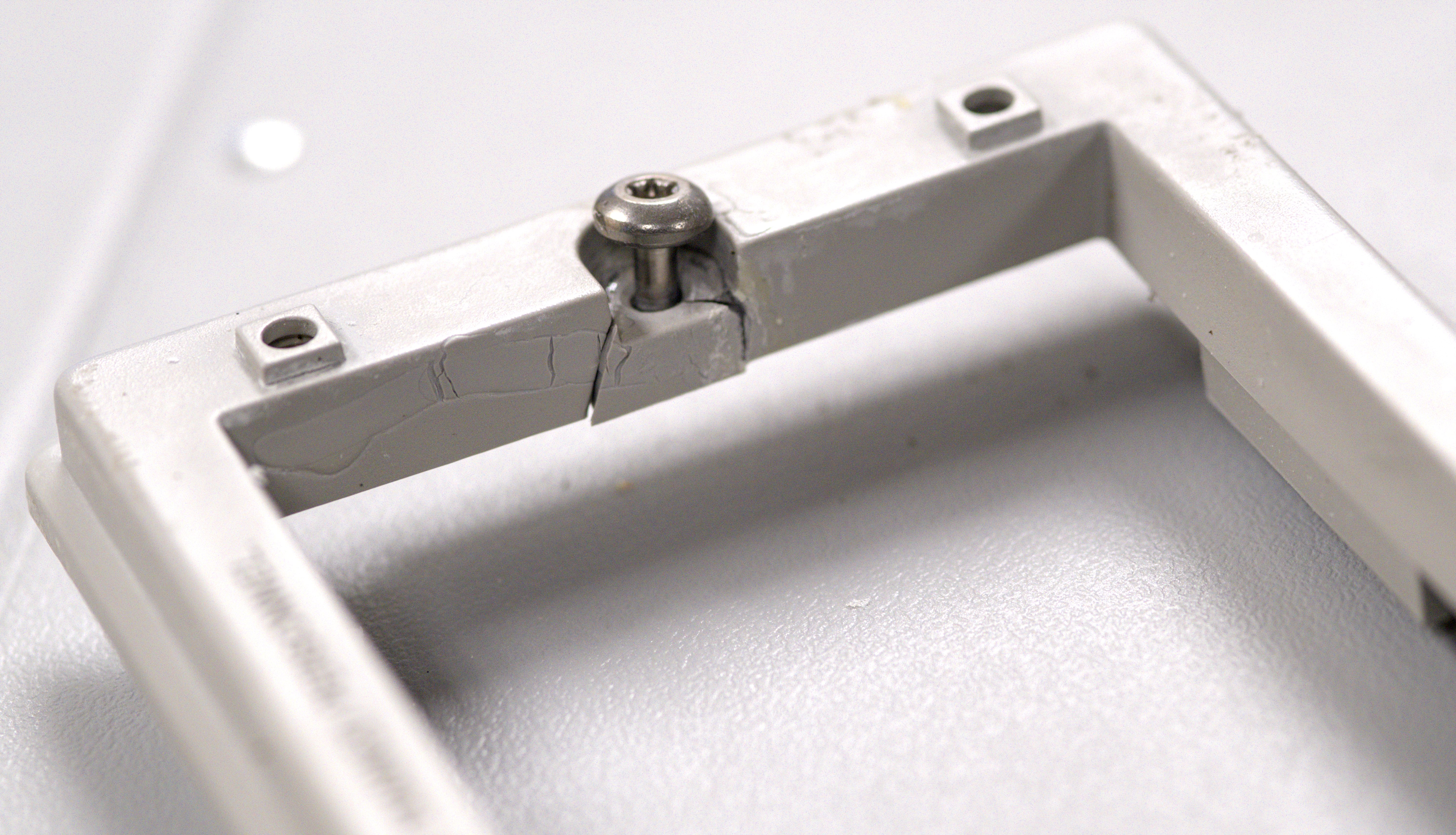
Rear bezel is all smashed up and damaged, but it was agreed and disclosed issue I was expecting to see. No compains or problems regarding damaged bezel.
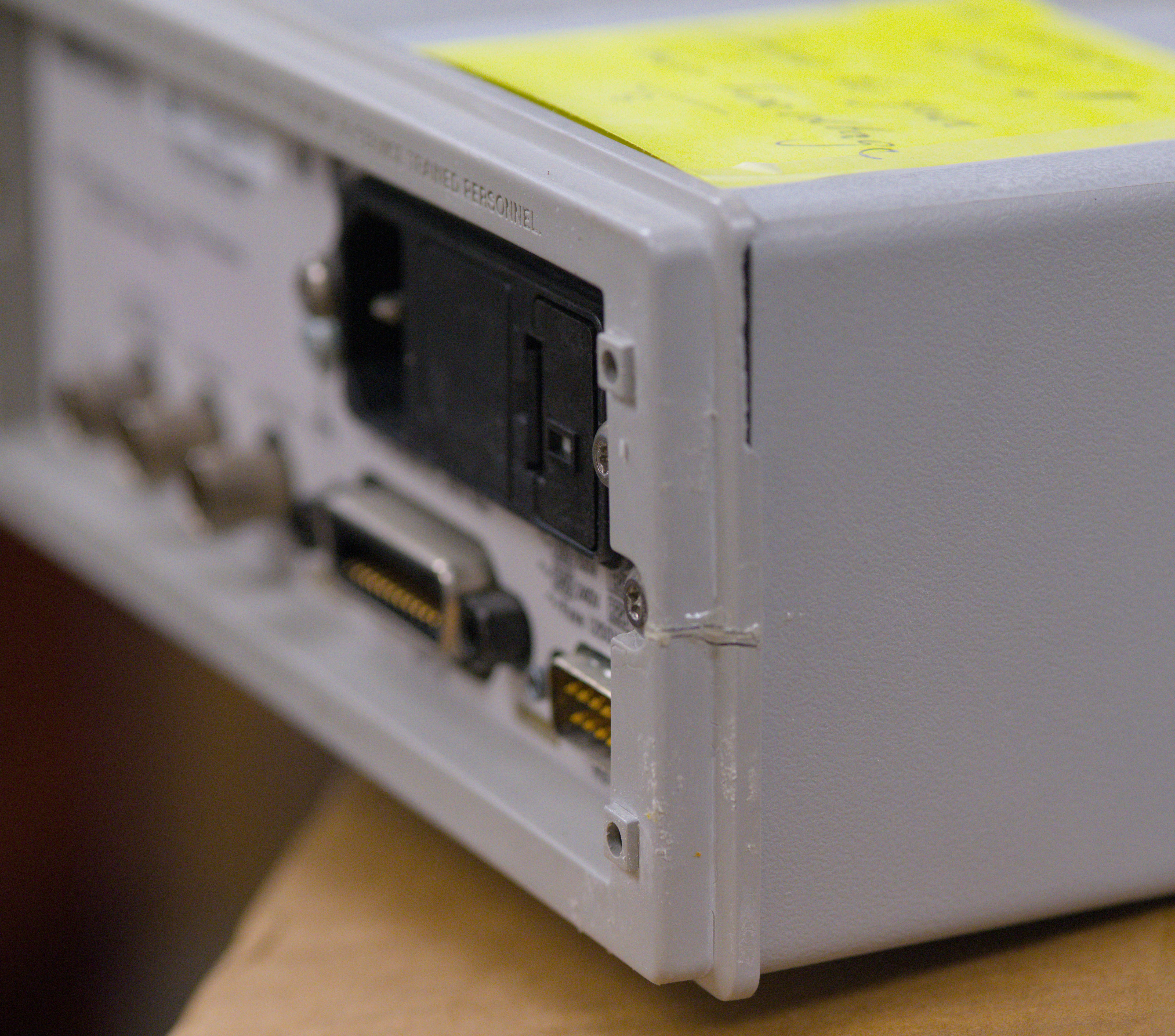
It’s not only cracked in half and epoxied together in repair attempt at the mount bolt point but also have busted up edges around. Many of the HP, Agilent and even newer Keysight instruments in half rack form-factor are using same rear bezels and they are not expensive to aquire as a replacement part. We’ll replace this bezel after instrument is restored to functional state.
One last image of the plastic damages and bits:
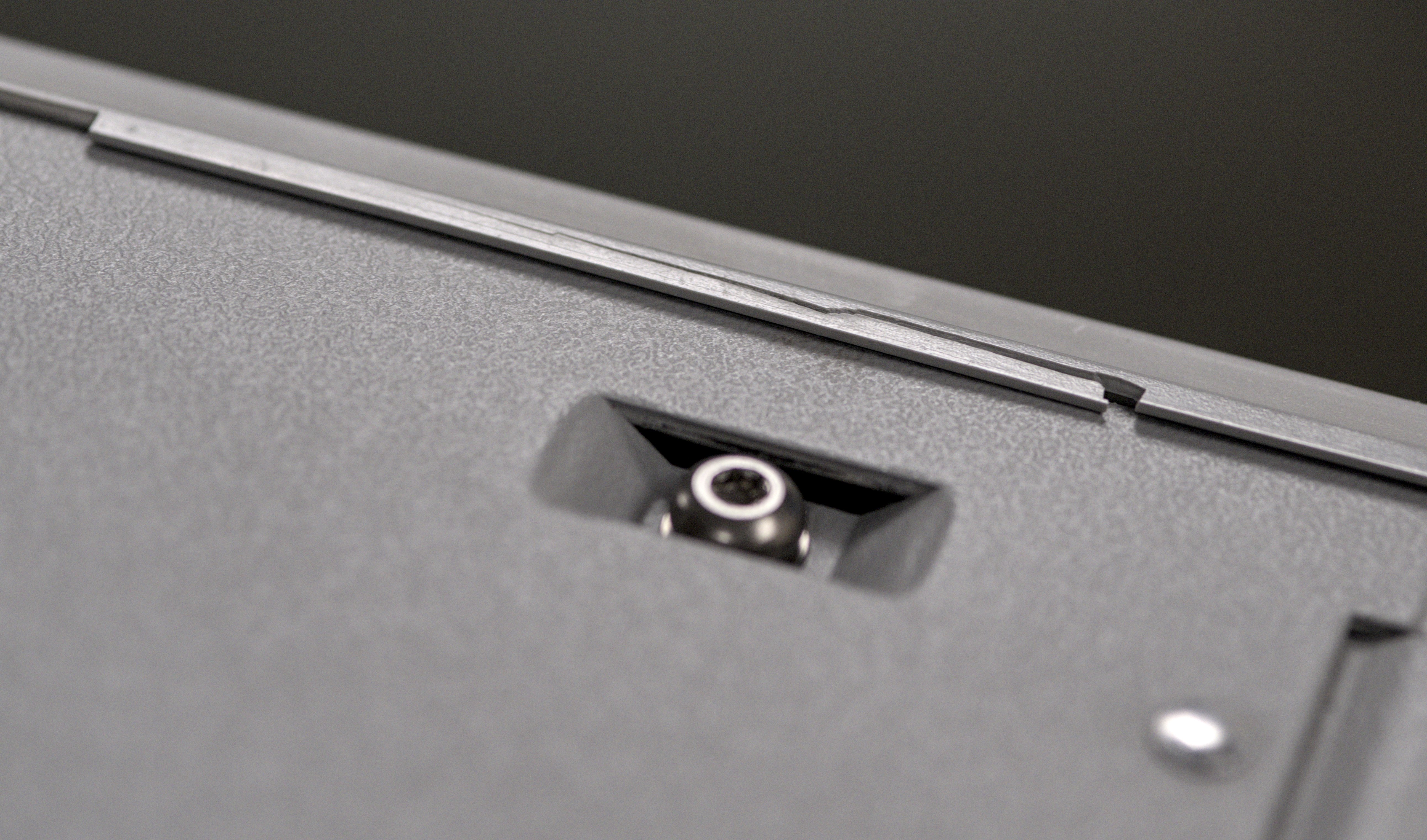
Removing bezel fastened with a pair of Torx T15 bolts and one grounding bolt of same size at the cover reveals the inner volume of the instrument. To my despair all the inside surfaces are also covered with fine styrofoam dust layer.

I could easily draw unhappy frowning faces on the cover inner surface. Whole instrument will require deep and careful cleaning to get rid of this, especially around sensitive nanovolt-type high impedance circuitry on PCBA.

Every surface is affected, no corner was spared. Normally black plastic air baffle cover looks like it had a sparkle paint job by styrofoam bits.
Front panel vertical surfaces show same condition.
Closer up on plastic shield cover:
“Snow” is covering all the custom chips and electronic bits on the mainboard as well. Getting it out between all the pins and tight spots could be tough and annoying.
Back side PCB is just as dirty.
But at least we got no visual damages or burned charred parts on the board visible yet.
34420A board is relatively simple and thanks to old Hewlett-Packard excellent documentation efforts we get full schematics, BOM list and nice detailed manual for 34420A. Keysight sadly actively spend time and resources to remove the schematics and BOM from the latest version of the manual. The question “why” remains to be asked.
One last image of the dusty cover:

Closer look at the input connector reveals first obvious issue. Can you see it yet on the photo below?
Yep, the red wire going to CH1 HI is broken right off. Maybe that’s all it takes to repair this instrument? Wouldn’t that be nice?
Manuals and datasheets
HP/Agilent/Keysight 34420A datasheet with specifications
HP 34420A User’s manual, Edition 1
Agilent 34420A User’s manual, Edition 2
Keysight 34420A User’s manual, Edition 3
Keysight 34420A User’s manual, Edition 7, May 2023
Agilent 34420A Service manual, Edition 1, December 1994, good schematics
Keysight 34420A Service manual, Edition 3, September 2018, with poor quality schematics
Keysight 34420A Service manual, Edition 4, July 2021, with schematics/BOM removed completely
HP/Agilent/Keysight 34420A scanned schematic pages
HPAK 34420A Safety/Regulatory Addendum
Making Low Resistance Measurements using the B2961A and 34420A
Precise Low Resistance Measurements Using the B2961A and 34420A
Fluke/HP 34420/SPRT and 34420/PRT NanoVolt/Micro-Ohm Meter Instruction sheet
Service Note 34420A-01: RS-232 communication error transmitted, affected XX-03-XX and XX-04-XX FW
Service Note 34420A-02A: RS-232 not working due to bad programmable IC for S/N US36000800-US36000921
Service Note 34420A-03: Infrequent GPIB Hang-ups, affects FW 3.0-XX-XX, S/N up to US36001171
Service Note 34420A-04: Inaccurate temperature readings, require rebuild, S/N up to US360001171
With every revision service manual getting worse and worse, loosing quality and removing vital bits of information for repair and maintenance. Latest Edition 4 of service manual removed replaceable parts table and all the schematics and parts location drawings. Why? To be the on par is just as poorly documented service manual for the only competitor to 34420A – Tektronix/Keithley 2182A? Well even that is not true since Keithley 2182A latest service manual from July 2022 has actual assembly drawings of their instrument in good details.
I can only express the appreciation to the contributors such as David who actually spent time scanning and digitizing their obsolete but very helpful manuals. This seem to be the only way for independent researches to preserve the information about servicing ageing but still very good test equipment, like 34420A.
Teardown, cleaning and repairs
After hours of cleaning I’ve finally got the instrument to decent shape and it’s time to look closer as the internal design. Each photo is traditionally available on xDevs in full 100 Megapixel resolution on click so be sure to check any details you’d like. 34420A contains all the key electronics on single mainboard with nice and elegant design. Architecture on the first glance is pretty traditional for a benchtop multimeter, except that we missing AC functions, high voltage dividers and rear input options.

Mains referenced circuitry, I/O connectors and mains entry filter are all at the back of the instrument. This meter does not have any fans or vent holes since power consumption with 120V 60Hz input is just 9.5 W.
Then we get floating digital section with main processor, gate-array logic chip, some SRAM and EEPROM firmware ROM (sadly soldered on).
Shileded transformer plugs into white 8-pin receptacle next to the front-panel ribbon cable connector. There are three linear regulators nearby with generous amount of copper polygon to act as a heatsink for thermal dissipation. All the analog magic happening on the top right side of the board with good old HP-branded LM399 ovenized buried zener reference.
Custom HP 1NB4-5035 logic chip with JFETs and switches for multislope as well as 1SK6-0001 gate array are the core of the A/D converter here. These custom ASICs are identical to parts used in HP34401A 6½-digit multimeter so in case someone needs them to fix 34420A sacrificing much cheaper 34401A might be a viable option there.
Precision resistors used for ADC current references are hidden in ceramic hermetic foil-resistor network RP1 from Alpha Electronics, marked DQP010 with specified TC ±5 µΩ/Ω/K. Per date code marking this 34420A was assembled and built around 36th week 1997 year, good 27 years ago. This means that all tantalum and electrolytic capacitors are due to replacement. After recent fireworks in Fluke 732B charger we are not taking any more chances with old caps.

Back side of the PCB does not have any components.

It is interesting to see lack of thermal baffle or cover on the bottom side. Perhaps HP decided that it’s not much need to have back sides covered for meeting the specifications of 34420A. Perhaps obvious experiment to try in our modification ideas?
ADC area and LM399 also does not have any covers but has some additional copper pour perhaps to equalize thermals better. This PCB is just two layers so no massive copper planes internally. PCB was also manufactured in 36 week 1997.

Glorious focus-stacked images with 100 MP resolution each of the front-end and ADC section are also available below.

Interesting to note LS4392 JFETs from Linear Systems used by HP as signalpath switches for various signals in the front-end.

For high gain stage used in 1 mV and 10 mV ranges HP designers used ultra-low noise JFET matched pair in hermetic TO-78 package from InterFET, IF3602. This N-type JFETs are based around monster large 2×2 mm geometry die N3600L and can sport voltage noise level of just 0.5 nV/√Hz. Next best device of such class is Linear System’s LSK389 and LSK489 with 1.8 nV/√Hz voltage noise specification. This low noise levels come at a price of huge capacitance. Enough to say, this device is also not cheap, at $64 USD retail price per piece and lead time at least 28 weeks. There are also single JFET versions of with this low-noise device, such as IF3601.
Let’s investigate the front end switching and routing of the signals from input LEMO connector. I’ve colorized important signalpaths on schematic diagram from the service manual. Red color indicate CH1 HI path, light blue CH1 LO, green is CH2 HI and darker blue is CH2 LO. Optorelay switches U120, U122, U124, U125 are marked in orange boxes, while traditional latching relays K101 and K102 are in lighter yellow boxes. Violet is CC line which is multiplexed voltage input line, as well as navy blue marking for LO reference. LEDs in optoswitches are driven with currents about 0.7 mA to limit their self-heating and themal EMF errors.
Section of the U126 contains high-voltage divider attenuator with 9.9 MΩ and 100 kΩ resistor elements for 100 V range. As we can clearly see this attenuator can be connected only to CH1 HI line by relay K102. Output of this attenuator is routed measurement circuitry from the LTC1050CS8 buffer U126. Set of MMBF5461 JFETs provide low-leakage signal level clamping and protection mechanism for multiplexed signals (Q121,Q122,Q128,Q129,Q132,Q133). There are also LS4392 switches Q125,Q126,Q130,Q134 as for isolation purposes to disconnect each signal from the input amplifier, likely used during auto-zero and precharge steps.
This instrument had faulty channel 1, did not measure any input signals since the input wire was broken off the connector. But restoring the connection did not improve the situation and CH1 was still reading random noise of the high input impedance voltage channel. Tracing signal from the input connector to front-end quickly revealed a culprit, which was bad solid-state switch. Original switches are HP HSSR-8400 which are unobtanium these days. After ordering replacement LH1510AAB SSR relay from Digikey (P/N LH1510AAB-ND) we can proceed to the repairs.
I’ll have to replace the damaged LEMO EVP connector bit later on after the repair is completely finished. After replacing both CH1 HSSR-8400 optorelays U120 and U125 with LH1510AABs instrument was reassembled for testing.
As expected this made the CH1 functional again. Now we can proceed with the more detailed calibration and performance testing.
Cleaning up front and rear panel also got this HP34420A looking much better. Rear side with replaced bezel and dust caps on BNC connectors looks almost like new now. Rear bezel in original HP meters had part-number 03478-88304 but current instruments replaced it with P/N 33220-88304. Newer black (dark-silver phantom grey Keysight colors) bezel is 33220-88314 is a bit cheaper.
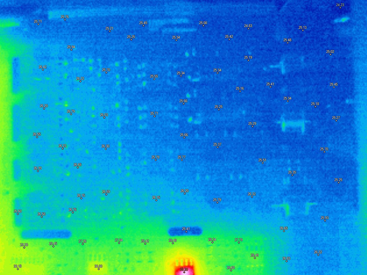
Thermal images of the 34420A mainboard
We got some of the thermal images and thermal gradients visualized with my friend Igor help and his 640×480 infrared imager. First let’s look at the LM399 zener reference area:
Hmm, lots of hot stuff nearby. Actually two small SOT23-3 parts nearby getting much hotter than LM399 itself. These are 3.3V zener diodes CR401 and CR402 that HP put in series to +18 and -18 V supplies. With zener diode voltage rails are dropped to ±15 V as result. U420 on the north section is quite warm at +53 °C is A/D converter’s opamp OP27GS. AD711 U402 is at much cooler +47.5 °C. Both of these opamps are powered from ±15 V rails.
Zooming out we can take a thermal image of the digital section of the board as well:
Two main regulators are at comfortable +52 °C, processor and digital ICs are barely registering over the ambient temperature with just few degrees of extra heat. Area around analog power linear regulators is around average +47 °C. Not a concern for any of the analog domain circuits.
Capturing similar image for overall analog section of the PCB shows few other hotspots. Slotted section with very front-end and JFET switches is stone cold with no visible gradients, as expected. Table below shows summary of the hot spots.
| Component | Recorded temperature | Function |
|---|---|---|
| CR401 3.3V Zener in SOT23-3 | +63 – 65 °C | Drop-down voltage rail from +18 to +15 V |
| CR402 3.3V Zener in SOT23-3 | +58 – 62 °C | Drop-down voltage rail from -18 to -15 V |
| U420 OP27GS opamp in SOIC8 | +58 – 62 °C | Slew-rate amplifier in A/D converter |
| U402 AD711JR opamp in SOIC8 | +58 – 62 °C | Output amplifier in A/D converter |
| U307 LT1124CS8 in SOIC8 | +60 – 61 °C | LNA Gain amplifier driver |
| U306 MC34081BD/SM in SOIC8 | +58 – 62 °C | LNA output amplifier |
| U314 AD712JR/SM in SOIC8 | +58 – 62 °C | LNA input bootstrap/driver |
| CR303 15V Zener in SOT23-3 | +49 °C | 15V zener |
| Q308 MMBT6429 NPN in SOT23-3 | +41 °C | Biasing BJT for LNA stage |
| Q305 MMBT6429 NPN in SOT23-3 | +42 °C | Biasing BJT for LNA stage |
Selected LM399AH with plastic heatshield armor heats up to temperatures around +60 – +65 °C. I’m little bit concerned about socket used to connect LM399A to the PCB and probably will later replace that with permanent fixed connection.
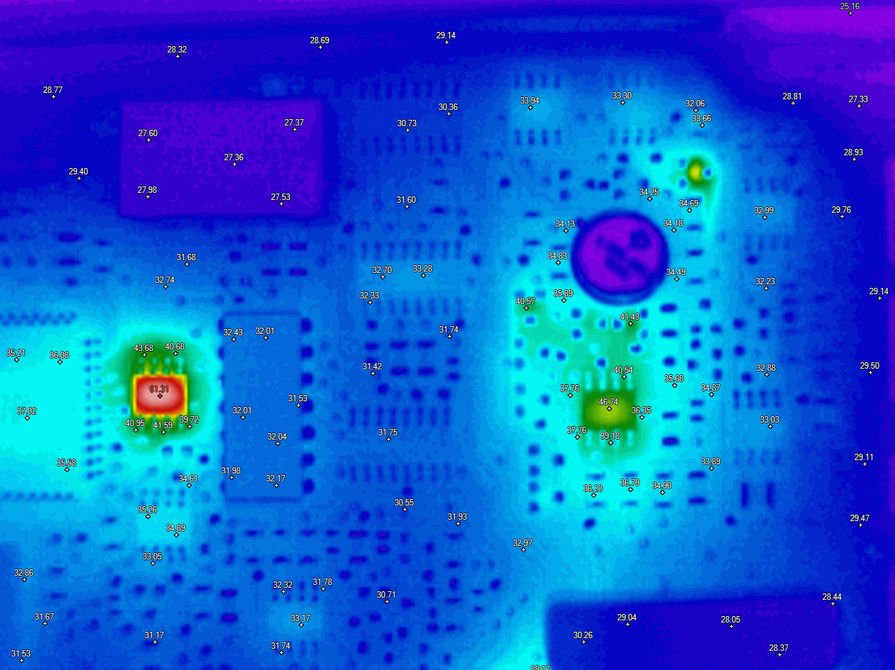
Channel and signal switching front end is stone cold with just thermal reflections and noise visible. This is good example of isothermal design, without any heat generating components in the area. Effective use of slot perforation is also obvious here.
Only warm +40 °C part in the relatively near area is MC34071D U203 which is a buffer driver for voltage reference input at U204 AD7524JR DAC.
Repair BOM and parts used during this project
| Manufacturer Part Number | Description | Quantity | Unit Price | Extended Price |
|---|---|---|---|---|
| LH1510AABTR | SSR RELAY SPST-NO 200MA 0-200V | 2 | $3.04 | $6.08 |
| G3VM-101ER1 | SSR RELAY SPST-NO 3.5A 0-100V | 2 | $11.15 | $22.30 |
| TLP3546A (TP1,F) | SSR RELAY SPST-NO 3.5A 0-100V | 2 | $4.00 | $8.00 |
| PVA3324NPBF | SSR RELAY SPST-NO 150MA 0-300V | 2 | $10.80 | $21.60 |
| PVA3054NPBF | SSR RELAY SPST-NO 50MA 0-300V | 2 | $7.57 | $15.14 |
| 34420-49321 | Window/front lens | 1 | $13.25 | $13.25 |
| 33220-88304 | Bezel rear | 1 | $27.00 | $27.00 |
| 5041-5288 | Black bumper kit | 1 | $31.91 | $31.91 |
Firmware revisions and dumps
Our contributors reported that various 34420A have different firmware revisions. Because firmware EEPROM chip in PLCC U502 is soldered directly on the PCB there is no easy way to read-back and backup the image. Firmware version string from these instruments consists of three numbers. First number is a main program version, stored by U502 near the main processor. Second is the mask ROM version of the small microcontroller on the outguard earth-referenced section of the board. And third last number is version of the firmware in the microcontroller on the VFD front-panel board.
| Meter, year | Serial number | Firmware reported | Binary file dump from EEPROM |
|---|---|---|---|
| xDevs.com HP 34420A, 36 week 1997 | US36000874 | 3.0-5.0-2.0 | N/A |
| HighVoltage Agilent 34420A, unknown age | MY42004??? | 10.0-5.0-2.0 | N/A |
| HighVoltage Keysight 34420A, unknown age | SG42000??? | 10.0-5.0-3.0 | N/A |
| chekhov 34420A, unknown age | ? | 5.0-5.0-5.0? | N/A |
| Steve’s 34420A, 27 week 1996 | US36000164 | 3.0-5.0-2.0 | N/A |
To our knowledge there is no detailed public change-list of firmware versions and no visible functional or performance differences between the versions. Per Service Note 03 our meter might be affected by the GPIB hang-up if the input overloaded in DCV function and TRIG Source set to external. To workaround service note suggests to disable VFD output with “DISPlay OFF”.
HP 34420A main firmware, 34420-????? REV 3.0
Keysight 34420A main firmware, 34420-88872 REV 10.0, thanks to Selena
Performance tests for 34420A
Now that instrument is working we can connect it to the voltage source, such as Fluke 5720A 7½-digit calibrator and capture some datalogs. As a reference instrument for higher voltage ranges I’ve attached calibrated and characterized tandem of HP3458A 8½-digit DMMs in parallel to DUT 34420A. They will be useful as linearity reference as well as calibration source instead of own Fluke 5720A specifications. One more modified HP 3459X was added as additional DUT for some comparisons as well.
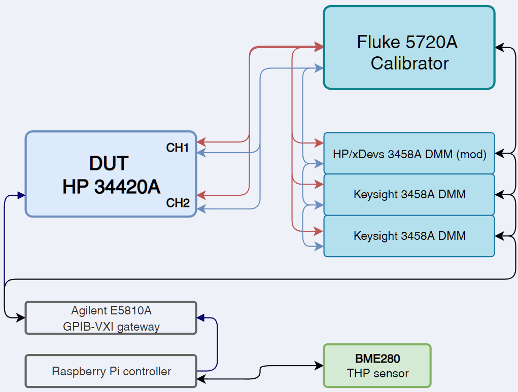
As usual we prefer automation to any kind of manual operator-intensive processes. Raspberry Pi with Python scripts were utilized to interface all of the instruments and store the data into DSV datafile for further analysis. Environment was monitored and logged from Bosch BME280 temperature/humidity/pressure sensor connected to I2C bus on the RPi SBC.
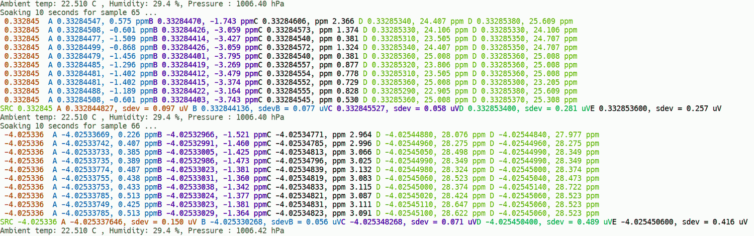
DCV random points data collection script, Python 2.7
This script talks via Keysight E5810A VXI11 LAN to GPIB converter to calibrator, three DMMs and DUT 34420A. It configures calibrator to locked 11 V range, configures all meters and NULLs the 3458As. Then it performs ACAL DCV for 3458As and start collection of the random voltage data points with all meters for 2048 points. Sequence to collect each point listed in following process:
- STEP 1: Configure calibrator output to random value in range from -10.9999 to +10.9999 V.
- STEP 2: Wait for 10 seconds to settle the voltage output
- STEP 3: Trigger start of the measurement for all meters, select CH1 for 34420A and trigger it too after 2 seconds
- STEP 4: Record reading from each 3458A and 34420A CH1 into variables
- STEP 5: Switch CH2 for 34420A and after 2 seconds trigger measurement on it
- STEP 6: Record reading from 34420A CH2 into variable
- STEP 7: Add all results into vectors, one per instrument
- STEP 8: Repeat the sequence from STEP 1 to 7 for nine times. Each sample is recorded for additional debug DSV log-file.
- STEP 9: Calculate standard deviation and median from each vector using Numpy library
- STEP 10: Record the standard deviation and median values into clean data DSV datafile with timestamps and environment data
This script does not perform any analysis or calculations on the resulted data, for that I’ve used separate script with Matplotlib graphing and filters. Each DVM is configured for NPLC 50 and same range. Script runs for some number of hours to collect enough statistics for further data analytics.
Script was written with obsolete Python 2.7 syntax and would need some modifications to operate in modern Python 3.x environment. Our approach is to keep the old tools that are working fine, instead of updating for the sake of updating to try keeping up with non-stop complications.
INL performance and condition as repaired
INL for 10 V range
Using script listed above we can process the datafiles and make some charts to take a look on initial performance figures from 34420A. First test was performed only on channel 1 to see if we are getting ballpark good values. Script above with small mods to change range I’ve acquired two datasets:
DSV datafile with all points for CH1 10 V analysis
DSV datafile with all points for CH1 1 V analysis
To perform the INL plots we need first to sort the datapoints according to voltage amplitude, not the timestamp. This is done automatically by the plotter script using simple sort function in dataframe. These scripts are newer and written to comply with Python 3.7.5 environment. Scripts require installed Matplotlib, Numpy and Scipy libraries. Plot scripts require one more external config file, available to download below as well.
Python 3.7 INL plotter/analysis script
Configuration file with parameters for quick INL data tests
Later data was captured with both 34420A channels and needed slightly modified script and config file:
Python 3.7 INL plotter/analysis script for 2 channel data
Configuration file with parameters for 2 channel data
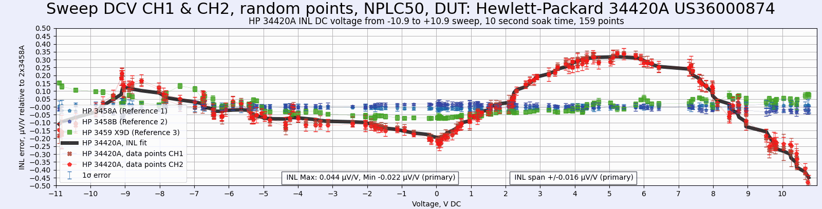
Now let’s take a look on the charts output. Just from this test we can extract quite a bit of useful information about the initial performance of this specific HP34420A nanovoltmeter. First, I like to check the most important basic DC voltage range, which is 10 V +20% overrange on this 34420A, just the same as 3458A.

Three charts display the following aspects:
- Top chart represents INL error against the HP3458A meters, in voltage points from -11 to +11 V in random points.
- Middle chart represents standard deviation (1 σ error) of each point from each instrument.
- Bottom chart shows temperature in the lab recorded during the point sampling. Points outside ±0.5 °C are filtered out from analysis.
Channel 1 shows somewhat squiggly INL within -0.45 to +0.4 µV/V of the range. Not great, not terrible and what one might expect from typical benchtop 6½-digit DMM. 1 σ error of the 34420A is about ±0.08 µV/V. Factory specification for the Keysight 34420A at full scale in 10 V range is ±0.65 µV/V so this specific instrument is meeting this limit without problems.
INL for 1 V range
Let’s switch to 1 V range and check performance there as well.

Here INL is slightly worse, sometimes going a tad outside of ±1 µV/V of the range. HP3458A also show slightly degraded INL but still far superior to the 34420A, which would be as expected from 8½-digit DMM with excellent INL history.
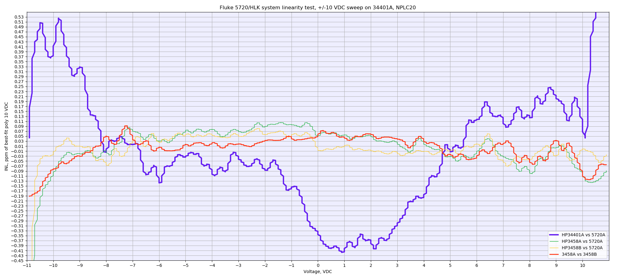
Looking back in the old HP 34401A repair article we can observe somewhat similar in 10 V amplitude INL from that 6½-digit DMM, which looks like typical INL from this shared ADC design.
Now we can dig a little deeper into 34420A sweeps. Unlike the 34401A here we got two channels and after repair channel 1 switched with LH1510AA optorelay while channel 2 still has factory original HP HSSR-8400 chips. Is there any difference? Also since we have all the RAW data points we can estimate gain calibration error of the 34420A after repair, before any adjustments.
DSV datafile with all points for CH1 10 V analysis
Running the data analysis script but with both CH1 and CH2 connected to same 5720A output we can again capture 10 V INL chart. There is no visible difference between either of the channels on this INL sweep. Which is a good news if you are using 34420A with channels substituion method.
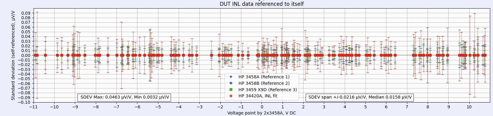
Standard deviation chart also shows same data points. There is some variation between the points but everything stays pretty low under ±0.1 µV/V which is the important aspect in this dataset.
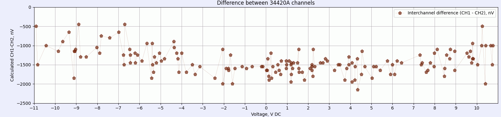
For next analysis let’s zoom really close to the actual difference measured between two channels. I’ve applied simple subtraction math and stored result as ΔV = (CH1 – CH2) * 109 vector to get readings in nanovolt scale. Now we can see some clearly visible difference. MATH NULL was not used prior to test start.
Zero value would mean that readings from both channels was exactly the same. But in this instrument I can observe offset between channels around -1.5 µV. This offset is reduced a little for voltages above 6 – 7 V.
Now we can also calculate the absolute gain error of each 34420A channel relative to reference tandem of HP 3458A DMMs:
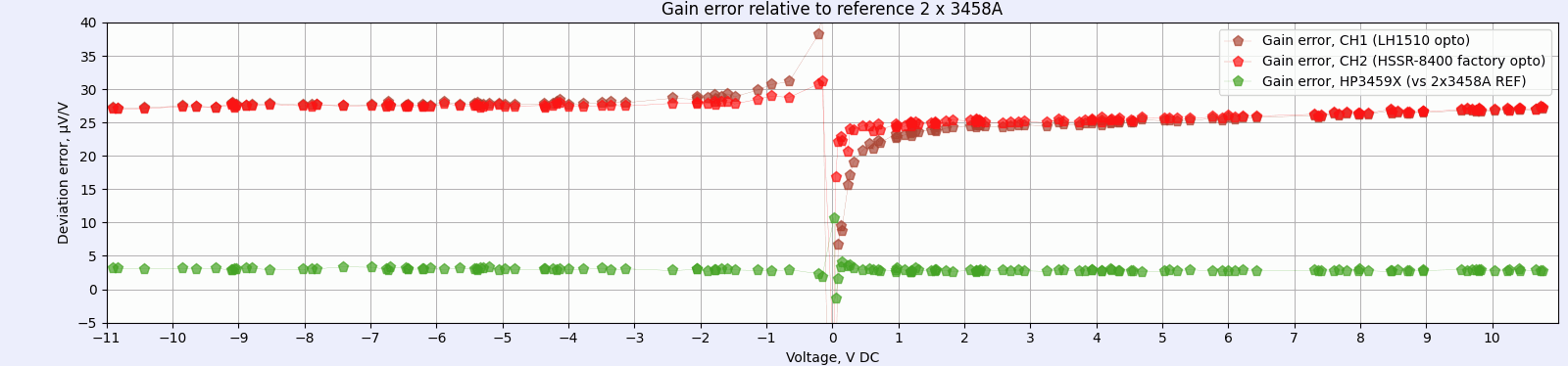
First of all, there is clearly visible gain error about 28 µV/V for negative DC voltage signals and about 25 µV/V for positive DC voltage signals. Experimental HP3459X with dual ADR1000 reference mod has flat gain error about 4.8 µV/V.
There is also slightly visible difference between CH1 and CH2 data points on this chart close to zero volt crossing signal. CH2 equipped with HSSR-8400 relays has visibly less gain error in this test.
And all the charts together in one combined graph:

Time delay for switching between channels in tests above was set to 2 seconds. Perhaps that is too short for switches to stabilize? Let’s increase it to 5 seconds and repeat the test?
DSV datafile with both channels INL sweep and increased 5 second delay after switching

Hmm, this test indeed looks a little bit better. Offset difference between channels is almost gone with just noise variation around -100 nV mark approximately. Gain error slope near zero point is also much smaller now on the last chart. This dataset is a shorter than the previous run, but it would be worthy experiment to investigate the timing required settling after 34420A channel is changed, to determine the setting that provides best measurement uncertainty and stability.
Before making any qualifying conclusions it is important to check factory specifications from manufacturer for the DUT.
| Function specification | Range | 24 hour, +23 °C ±1 °C | 90 day, +23 °C ±5 °C | 1 year, +23 °C ±5 °C | TC, +28 °C to +55 °C |
|---|---|---|---|---|---|
| DC Voltage, either channel | 0.001 V | 25 µV/V/reading + 20 µV/V/range | 40 µV/V/reading + 20 µV/V/range | 50 µV/V/reading + 20 µV/V/range | 4 µV/V/reading + 1 µV/V/range |
| DC Voltage, either channel | 0.01 V | 25 µV/V/reading + 20 µV/V/range | 40 µV/V/reading + 2 µV/V/range | 50 µV/V/reading + 3 µV/V/range | 4 µV/V/reading + 1 µV/V/range |
| DC Voltage, either channel | 0.1 V | 15 µV/V/reading + 3 µV/V/range | 30 µV/V/reading + 4 µV/V/range | 40 µV/V/reading + 4 µV/V/range | 4 µV/V/reading + 0.6 µV/V/range |
| DC Voltage, either channel | 1 V | 10 µV/V/reading + 3 µV/V/range | 25 µV/V/reading + 4 µV/V/range | 35 µV/V/reading + 4 µV/V/range | 4 µV/V/reading + 0.4 µV/V/range |
| DC Voltage, either channel | 10 V | 2 µV/V/reading + 1 µV/V/range | 20 µV/V/reading + 4 µV/V/range | 30 µV/V/reading + 4 µV/V/range | 1 µV/V/reading + 0.2 µV/V/range |
| DC Voltage, only CH1 | 100 V | 10 µV/V/reading + 4 µV/V/range | 25 µV/V/reading + 5 µV/V/range | 35 µV/V/reading + 5 µV/V/range | 4 µV/V/reading + 0.5 µV/V/range |
Total gain error about +25 µV/V relative to reference 3458A is still within 1 year specifications for Keysight 34420A even without adjustment and after repair! Pretty happy with this result so far. It is unknown when this specific 34420A was last time adjusted since there is no mechanism to store the date of last adjustment in these instruments.
Next steps would be to evaluate lower voltage ranges. For this I’ll need some more hardware and better temperature stability of the environment.
TBD.
Calibration adjustment and verification
INL was checked after adjustment (per service manual) and confirmed good for main 10V range. Setup and methodology was same as earlier, so I’ll not repeat the description here.

Temperature coefficient testing
+10 V point test, both channels
For testing HP34420A stability across different ambient temperatures instrument was placed in the TEC air-bath with programmable temperature sweep from +18°C to +35 °C. Both reference 3458As (outside of the chamber) and DUT (inside) were connected to same constant DC voltage source, Fluke 5720A calibrator. TC test took 78 hours to complete and both CH1 and CH2 were monitored. All meters were configured to use NPLC 100.
Temperature sweep with 34420A across temperatures, fixed +10 V point, NPLC100
Initial sweep on 10V range stability revealed rather noticeable positive temperature dependency about +0.96 ppm/°C. Both channels show nearly identical performance. Reference 3458A were used to monitor stability of the used source confirmed good confidence in data.
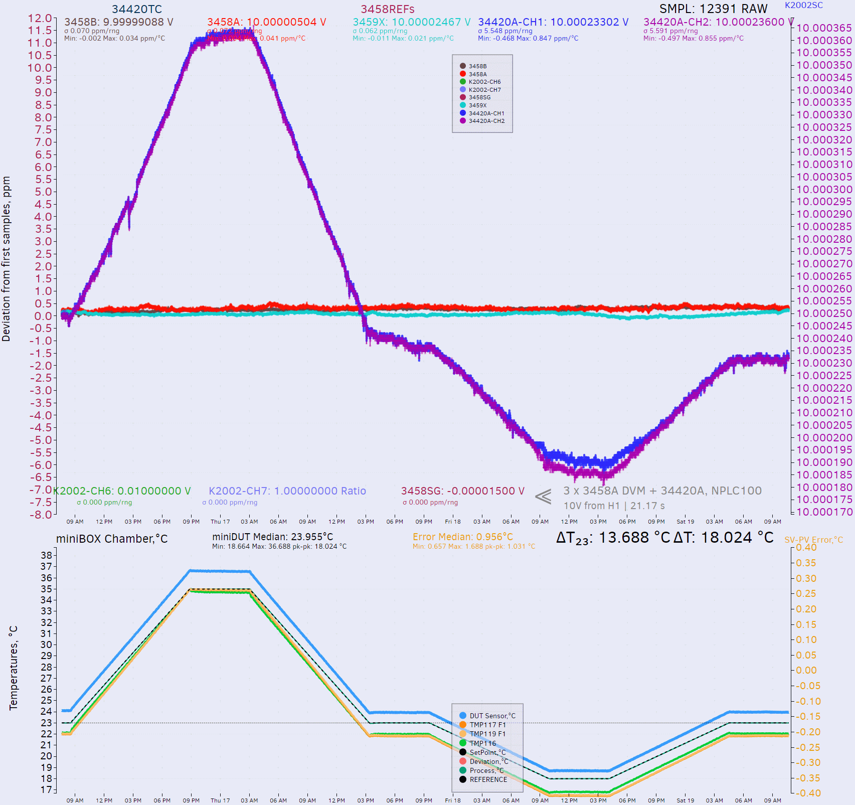
There was some small shift of the measurement value after the +35 °C cycle about -1.4 µV/V, perhaps due to humidity conditions change in the meter. Cooler sweep to +18 °C and back to +23 °C shifted value once again to additional -0.5 µV/V. CH2 demonstrated marginally worse TC on the colder temperatures cycle.
Additionally during this test another unwelcome effect of popcorn noise jumps observed in data. Most likely this is a result of LM399 jumps. Yet another reason to replace the onboard zener reference with something better.
+1 V point test, both channels
Same test was repeated across temperature range +18 °C to +35 °C for the lower 1 V range using fixed positive full-scale point, sourced from same Fluke 5720A calibrator and measured by three HP3458A DVMs in parallel. 34420A was not removed between tests.
Temperature sweep with 34420A across temperatures, fixed +1 V point, NPLC100
Performance for hotter temperatures span is pretty much same as +10 V range, but cooling sweep below +23 °C show a bit smaller deviation.
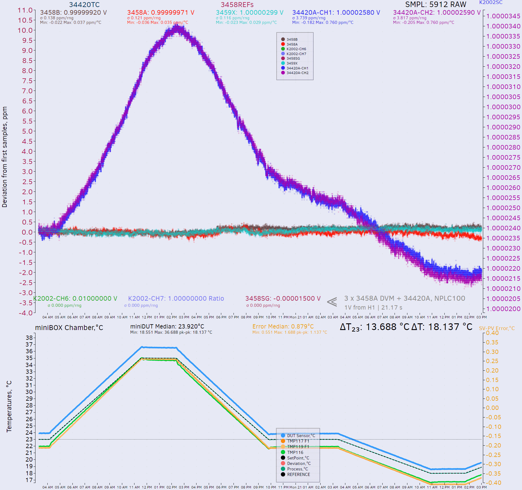
Gain error using 1 V range full-scale is pretty similar to 10 V from INL sweep test, about -24.5 µV/V relative to calibrated recently HP 3458A DVM. This is also inside of the tolerances for 1 year limit specification from Keysight. Based on these two ranges meter is working reasonably good even prior to adjustments. I’ve decided to abort this test before complete cycle back to standard +23 °C air-bath temperature and continue ahead with lower range TC sweep next.
+100 mV point test, both channels
First test would be to use same setup with directly connected Fluke 5720A calibrator and tandem of HP3458A DMMs configured for same 100 mV range. This is the easiest setup and can be replicated by any calibration laboratory. 100 mV direct connection TC sweep cycle configured for 68 hours time span with ramp speed defined by 12 hours duration slopes.
Temperature sweep with 34420A across temperatures, fixed +0.1 V point, NPLC100

+10 mV point test, both channels
For this lower voltage point new configuration utilize more complicated setup with addition of a voltage low-thermal EMF divider from Keithley, Model 262. Calibrator output was configured with remote sense active and sense terminals at 5720A connected to sense posts at the divider using copper spade lug forks. Divided output connected to meters input with low-thermal adapter, placed in the thermal isolating box together with divider itself. Calibrator output value was set to 1 V according with divider configured for 1:100 (102) ratio to obtain correct full scale 10 mV signal. Divider is set to fixed positive polarity output. Meters were NOT nulled to the zero, since in TC sweep test we only worry about relative change and offsets are not as important here.
Short test 34420A vs 3458A, direct 5720A fixed +0.01 V point, NPLC100
Quick check on the noise reveals that calibrator output for 10mV signal is noisier than 34420A and more elaborate setup with use of divider is a worthy improvement. Full TC sweep with K262 divider connected as described:

+1 mV point test, both channels
For this lower voltage point new configuration utilize more complicated setup with addition of two resistance standards to form a low voltage low-thermal EMF divider. This is done with help of Fluke 742A-10k and Fluke 742A-1 resistance standards with good calibration and known value. These resistance standards were connected in series using current terminals to form a voltage divider and 10 V full scale voltage applied to the divider input. Calibrator output was configured with remote sense active and sense terminals at 5720A connected to the resistor binding posts using copper spade lug forks. Sense output terminals from the bottom 1 Ω resistance standard were connected then to HP 34420A input to obtain 1 mV signal. Calibrator output value was adjusted according to calculated value of the resistance ratio to obtain correct full scale 1 mV signal. Most sensitive 1 mV DC range in 34420A inherits same uncertainty specifications from the manual so I’d expect similar performance in this test as well.
Temperature sweep with 34420A across temperatures, fixed +0.001 V point, NPLC100

Testing different SSR for channel switching
To test the difference between different optoswitches I’ve acquired number of the variants from Digikey. Let’s have a brief look on some key electrical characteristics:
| Part | Maximum rating | Output off state current | On state resistance | Isolation resistance | Turn-on time | Output capacitance | Voffset |
|---|---|---|---|---|---|---|---|
| Original HSSR-8400 | ± 400 V, 150 mA | 0.1 nA, 60V at +25 °C | 10 Ω | 100 GΩ 500VISO, 45%RH | 1.8 ms | 72 pF at 1 MHz | 1 µV at IF 5 mA, Iout = 0 |
| LH1510AABTR | ± 200 V, 200 mA | 0.5 nA, 100V at +25 °C | 12 Ω | 1000 GΩ 500VISO, 60%RH | 2 ms | 39 pF at 1 MHz | ? |
| G3VM-101ER1 | ± 100 V, 3.5 A | 10 nA, 100V at +25 °C | 0.05 Ω | 1 GΩ 500VISO, 60%RH | 5 ms | 450 pF at 1 MHz | ? |
| TLP3546A (TP1,F) | ± 100 V, 3.5 A | 10 nA, 100V at +25 °C | 0.08 Ω | 50 GΩ 500VISO, 60%RH | 5 ms | 450 pF at 1 MHz | ? |
| PVA3054NPBF | ± 300 V, 50 mA | 0.5 nA, 5V at +25 °C | 160 Ω | 100 GΩ 500VISO, 60%RH | 0.06 ms | 2.2 pF at 1 MHz | 0.2 µV at IF 5 mA, Iout = 0 |
| PVA3324NPBF | ± 300 V, 150 mA | ? | 24 Ω | 100 GΩ 90VISO, 60%RH | 0.11 ms | 6 pF at 1 MHz | 0.2 µV at IF 5 mA, Iout = 0 |
Noise performance in factory condition with original zener reference
TBD
Modifications and experiments
Modification with ADR1399 zener and noise/INL tests
TBD
Modification with ADR1001 zener module and noise/INL tests
TBD
Summary and conclusion
TBD
Total time spent repairing, documenting and calibrating this 34420A is provided in summary table below
| Timelog | Hours | Description |
|---|---|---|
| October 2024 | 5 | Initial article draft compose, discussion with xDevs IRC members |
| October 2024 | 7 | Cleaning, repair and recording video |
| October 2024 | 6 | Video part 1 editing |
| October 2024 | 18 | INL sweep as repaired, 10V |
| October 2024 | 8 | INL sweep as repaired, 1V |
| October 2024 | 24 | INL sweep against 3458A, 10V both channels |
| October 2024 | 80 | TC sweep for 10 V point, as repaired, not adjusted/modified |
| October 2024 | 50 | TC sweep for 1 V point, as repaired, not adjusted/modified |
| October 2024 | 80 | TC sweep for 100 mV point, as repaired, not adjusted/modified |
The author would like to express our appreciation to everyone contributed to this project, especially Martin, Todd and David. Discussion is very welcome thru comment section or at our own IRC chat server: irc.xdevs.com (standard port 6010, channel: #xDevs.com). If you have information and interesting ideas on 34420A hardware modifications not mentioned or listed in this article, feel free to provide them and xDevs will test and add them with next article update.
Projects like this are born from passion and a desire to share how things work. Education is the foundation of a healthy society - especially important in today's volatile world. xDevs began as a personal project notepad in Kherson, Ukraine back in 2008 and has grown with support of passionate readers just like you. There are no (and never will be) any ads, sponsors or shareholders behind xDevs.com, just a commitment to inspire and help learning. If you are in a position to help others like us, please consider supporting xDevs.com’s home-country Ukraine in its defense of freedom to speak, freedom to live in peace and freedom to choose their way. You can use official site to support Ukraine – United24 or Help99. Every cent counts.
Modified: Oct. 26, 2025, 12:07 a.m.
References
- Previous teardown and repair of 34420A
- Keysight 34420A page
- TheSignalPath : HP 34420A repair video
- Tektronix/Keithley 2182/2182A repair notes
- HP 34401A repair article
- IanJ's video about HP 34401A repair.
- Various experiments and hacks for old 34401A DMMs
- Blog about using 34420A for sampling
- xDevs.com TECKit : TEC controller/datalogger application
- xDevs.com TCkit : TC analytics plotting application