- Intro and motivation
- Disclaimer
- Manuals references
- History of prototype EP74 HP3458A, in memory of George Hnatiuk
- Rebuild workflow
- Bad PCBAs repairs
- August 2023 update on A3 stability
- Benchmarks and tests of restored DMM before any experiments
- Special option for additional outguard shields
- Lower noise A9 voltage reference PCBA with new ADR1000 6.62V zener chip
- Benchmarks and tests on mk1 “P3459” DMM
- Little fun mod – painting the rest of the covers black too
- Conclusion and summary
Intro and motivation
This is work in progress project, updates will be posted frequently.
It’s been a long while since we looked at famous 8½-digit DMM HP 3458A last time. Good eight (yes, 8!) years passed since xDevs.com acquired and repaired first broken HP 3458A. All that was documented and shared in first online 3458A repair article back in 2015. That 3458A is still going strong with non-stop 24/7 operation every day, delivering DCV measurements and handling metrology experiments daily at xDevs.com. Since 2015 xDevs helped and repaired more than 10 different HP and Agilent era 3458As and have three healthy units in constant use all year long with periodic performance verification and stability checks.
Links below are useful to refresh reader’s memory to some of the past HP3458A units publications:
- First xDevs.com HP 3458A restoration
- Second xDevs.com HP 3458A restoration
- HP 3458A repair for a friend
- HP 3458A repair and FRAM upgrade by TEKTRON
- Experiments with HP 3458A shunts
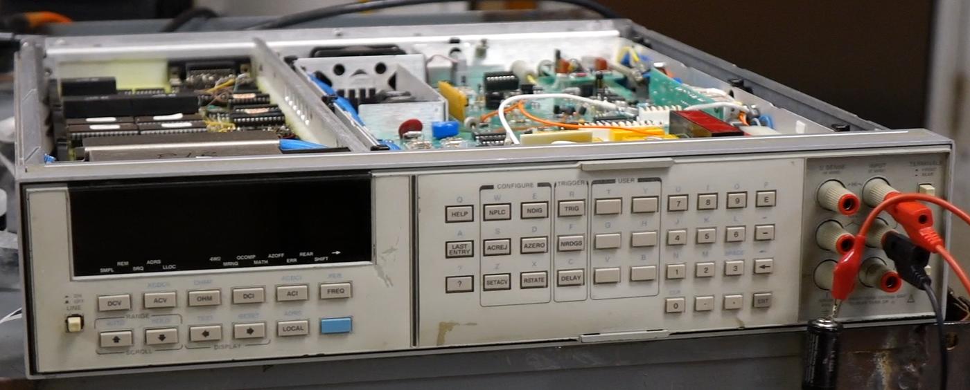
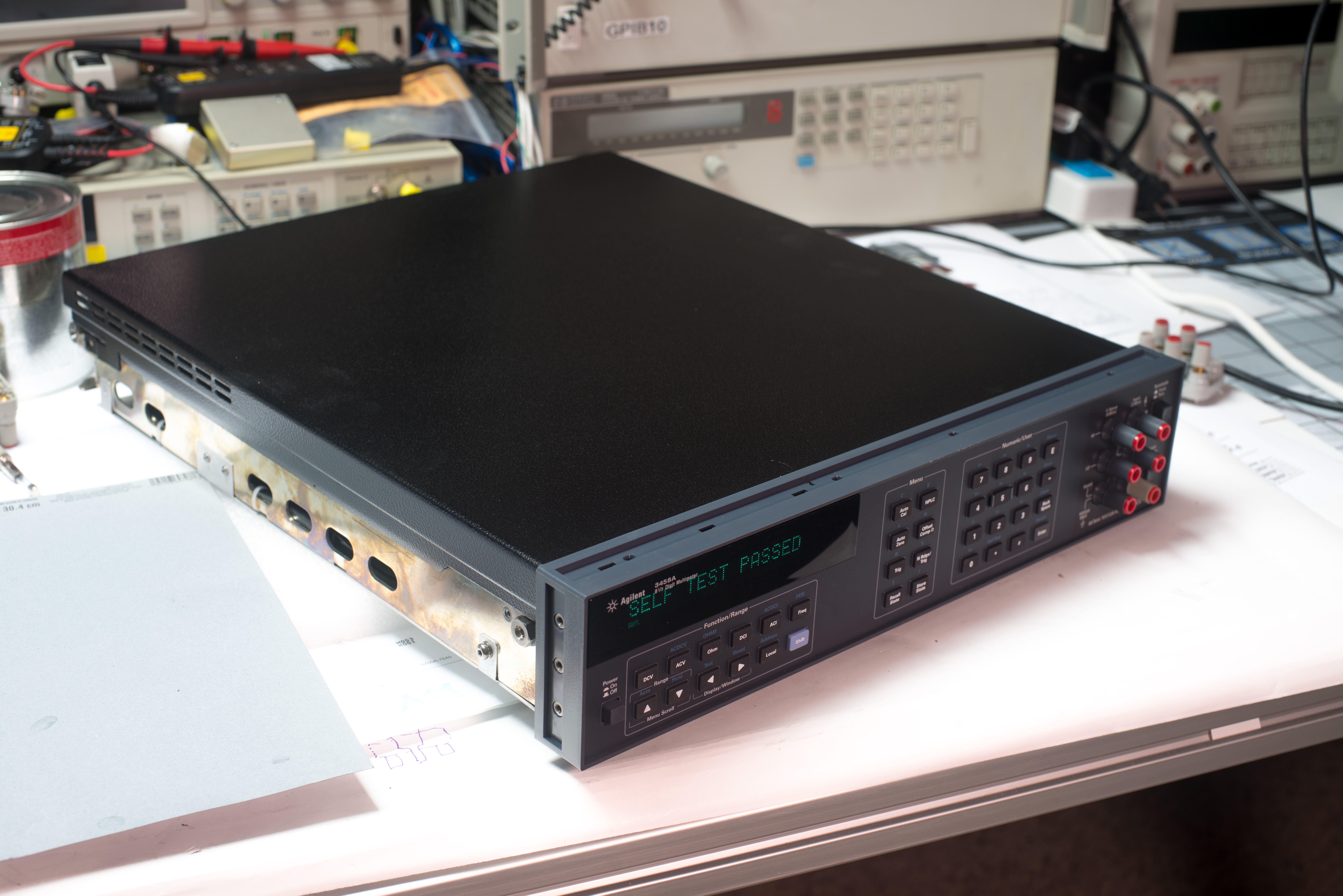
Article here is aimed to show us HP3458A glory some more. This time is not about some easy epay-special HP 3458A repair with board and Elantec comparator swaps. This time we will raise the bar and try to rebuild one fully working 3458A out of destroyed scrap donor and reject boards and parts from past 3458A repairs. This is also truly a community project, as number of people donated their busted components and bits to make it happen.
Please note, that instrument built from bad parts and showcased in this article will never leave the xDevs lab or be shipped to commercial laboratory for any formal calibration. This gives some freedom in modifications and doing otherwise questionable modifications to it. This is important to explain this fact before any readers get angry thinking we ruined valuable and desired good instrument for a sake of the article.
It will be a very interesting build and will give us a chance to dig into HP3458A operation like never before. Key motivator for this new project, codenamed P3459 is NOT just repair or rebuilding yet another boring 8½-digit HP3458A DMM but actually test some of the insane ideas on 3458A hardware. Few of these ideas are listed below for a teaser:
- Replacement of the LTZ1000A reference on A9 Voltage Reference to lower noise ADR1000 zener chip
- Testing different lower-noise modern opamps on A3 A/D converter board instead of original LT1001
- Removing input protection on DCV ranges to test noise limitations of input front-end
- Testing different lower noise preamps for DCV path on A1 DC board
- Trying battery powered operation of 3458A, eliminating transformer and front panel display
- Testing temperature coefficients of various circuits and functions
- Testing better voltage divider for 100 and 1000 VAC/VDC ranges
- Test operation without fan, air draft covers and other voltnut-approved paraphernalia
- Testing Ohm current source noise and stabililty, trying to improve it for better resistance transfers.
- Testing electronic front/rear inputs switching with relays to automate comparisons, like in Datron 1281/Fluke 8508A/etc.
All of these silly ideas require quite intrusive modifications of original circuitry and lot of high-risk experiments. It would be heart-breaking to waste a good fully-working HP3458A DMM to answer these questions. However with P3459 project rebuilt from scrap parts such experiments would be justified. In worst case we just made bad rejected parts … well, just still bad. No loss of good 3458A would be involved.
But before we may begin, main job is to bring all this random assembly of stuff to a working condition so it could function as normal HP3458A DMM.
As always on xDevs.com, all photos in this article are clickable for high-definition version.
People are still wondering with question “Is it worth to buy broken dead 3458A for XXXX$?. Well, simple answer is – No, it’s a big risk. If you asking yourself about this, then you are not ready for it. Buying broken or used 3458A for “good price” and fixing it might not be an easy way of getting good 8½ DMM, when multiple hidden costs considered. If unit stated as “untested/unknown/don’t know how to test” and not to have shown self-test result, it could have hardware failures. Paid cost for such a unit WITH proper repair can easily exceed cost of buying a fully tested unit. If unit’s photo shows it as powered up but you can see “ERR” on display, it also means there is fault detected. Keysight have standard 3458A repair + recalibration cost at [$2660, 2015 price] now $3.4k USD. Calibration alone of fully functional unit is likely to be over $1000 USD. Also old units manufactured earlier than 2005, would have Dallas NVRAM batteries already near end of life, with risk of losing calibration data any day. So even if you buy meter for “cheap” 1000$, you can be easily be held back by 2000-3000$ more to fix it and get calibrated.
Damaged parts (and current status as of April 2024):
- A1 board damaged, untested TBD
Second A1 board bad%FixedA2 board missingReplaced with bad board that was repairedA3 board not working, U180 damaged TBDA3 board replaced, U180 is drifting slowly {color:#880000}- -A3 board is replaced with 3rd board, so far stable good <0.012 ppm/day Checking drift
A4 inguard PSU boardGoodA5 Processor boardRepairedA6 board is broken, No power to CPU A5 boardFixedMissing fuse holder on A6 donor boardReplacedMissing fiber optic cables.ReplacedDamaged plastic front panelReplaced- Front panel has parasite pixels and weak VFD Fixed pixels, VFD brightness deemed acceptable
Mains power transformer.GoodNo legsReplacedOld electrolytic capacitors on A6,A4 PCBsReplaced- Prone to explosions Schaffner FN 323-3/05 EMI/mains filter TBD
Disclaimer
Redistribution and use of this article or any images or files referenced in it, in source and binary forms, with or without modification, are permitted provided that the following conditions are met:
- Redistribution of article must retain the above copyright notice, this list of conditions, link to this page (/fix/p3459/) and the following disclaimer.
- Redistribution of files in binary form must reproduce the above copyright notice, this list of conditions, link to this page (/fix/p3459/), and the following disclaimer in the documentation and/or other materials provided with the distribution, for example Readme file.
All information posted here is hosted just for education purposes and provided AS IS. In no event shall the author, xDevs.com site, or any other 3rd party, including HP/Agilent/Keysight be liable for any special, direct, indirect, or consequential damages or any damages whatsoever resulting from loss of use, data or profits, whether in an action of contract, negligence or other tortuous action, arising out of or in connection with the use or performance of information published here.
If you willing to contribute or add your experience regarding HP/Agilent/Keysight instruments repairs or provide extra information, you can do so following these simple instructions
Manuals references
A User’s Guide to Keysight 3458A Front Panel Operation
3458A Multimeter User’s Guide, Edition 7
Keysight 3458A Multimeter datasheet
Agilent 3458A : Quick Reference Guide, Edition 2, Dec 2000
3458A Multimeter Calibration Manual, Edition 7
3458A Multimeter Calibration Manual, Edition 6
We would also highly recommend book Sampling with 3458A, ISBN 978-961-94476-0-4 written by recognized metrology expert Rado Lapuh. Book showcases performance of 3458A functions and practical programming and application examples for high precision AC and DC sampling with HP3458A DMM.
Service notes
There is also number of service notes/engineering changes were published during years of 3458A’s lifecycle. If your unit is old, worth to check if any of them required to do.
Service note 3458-01C : A/D Linearity Improvement
Service note 3458-04A : Apparent failure at turn-on or when given a “RESET” command
Service note 3458-07B : Modification to Fix Intermittent Error “Multislope Rundown Conversion”
Service note 3458-08A : Incorrectly Labeled Line Voltage Switches May Cause Switch Setting Confusion
Service note 3458-10A : 3458A Documentation Available As “On-Line” Files
Service note 3458-12B : Outguard Firmware Upgrade: Enhancements, Fixes, & Changes
Service note 3458-12C : Outguard Firmware Upgrade: Enhancements, Fixes, & Changes
Service note 3458-13A : GPIB Communication Failures Using the 3458A
Service note 3458-14B : Calibration Error After Power “On” or After an “ACAL”
Service note 3458-17 : Errors May Occur if ACAL AC is Initiated From the 4-Wire Ohms Function
Service note 3458-20 : Bad SRAM causing Cal Ram batteries to fail prematurely
Rebuild workflow
Before starting any repair, good idea to read thru repair manuals, to get idea of board functions and purpose. HP has both assembly and component level repair manuals, which include full schematics and board assembly drawings. AFAIK it’s the only 8½ DMM which have complete schematics. I still remember repair efforts and countless hours without schematics, deciphering circuitry in Keithley 2001 DMM.
3458A Multimeter Assembly Level Repair Manual, Edition 2
3458A Multimeter Component Level Repair Manual
HP3458A Prototype #74 unit history, in memory of George Hnatiuk
Before we go deep into hardware and measurements I’d like to dedicate this project in memory of George Hnatiuk whom we lost on September 12, 2022. George was one of the key Hewlett-Packard engineers on 3458A project back in 1980s responsible of A1 DC board design. Thanks to his and team expertise at HP we today have still unrivaled DC performance of 8½-digit 3458A DMM, even 40 years later today.
I’ve had privilege to discuss metrology, DMM projects and engineering in general with George in 2021 and 2022. He was very supportive to test equipment community, helped countless number of people online and offline with their HP3456A, HP3457A and other HP-era equipment. So I hope a little insight into his prototype HP3458A engineering unit #74 can be helpful to inspire today’s young generation to pursue career, sharing and transferring knowledge and passion in test equipment instrumentation and measurements industry.
George kindly shared some photos and videos of his early engineering prototype meter. It was unit that George used for development and testing various ideas back in 1983-1985 year during the development. This unit had engineering prototype number #74 and is very different to production 3458A hardware we are all familiar with.
His prototype unit was based around HP 3457A chassis with customized 3457A-style front panel. Overall design is somewhat close to modern 3458A units, but the circuit boards are far from being same. This meter was early enough not to have ACAL functionality just yet, but otherwise it was still working and functional at the time in 2021.
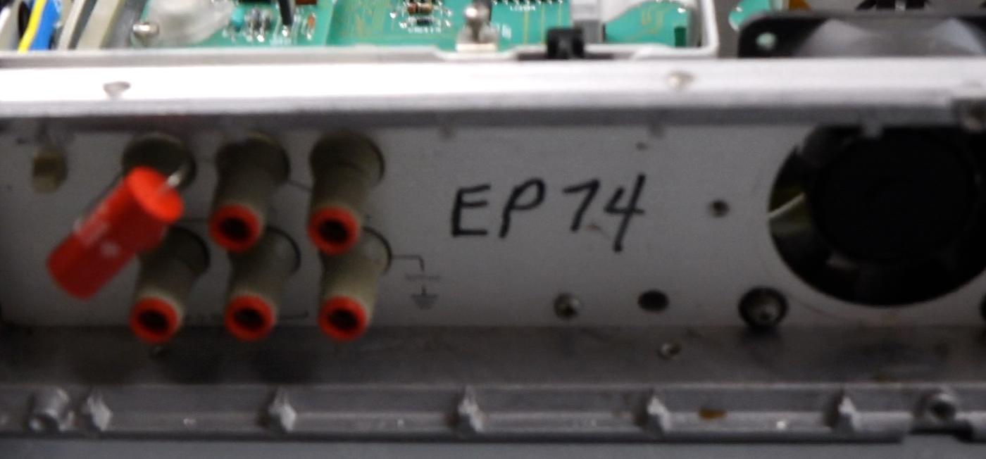
VFD glass is almost same as current HP3458A but extra status annunciations are also marked on the display lens. Buttons are following old 3457A style with plastic caps instead of modern rounded larger rubber pads. At power on EP74 3458A does not do self-test but gives a message “READY FOR ACTION” briefly.
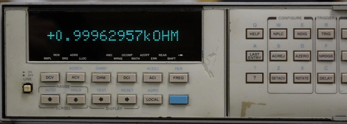
Interesting to note that in resistance mode instrument had ability to show full 8½-digit resolution readout. Modern 3458A firmware truncate value to smaller resolution on display, even though have full 9½-digit measurement performed internally and provided over GPIB bus.
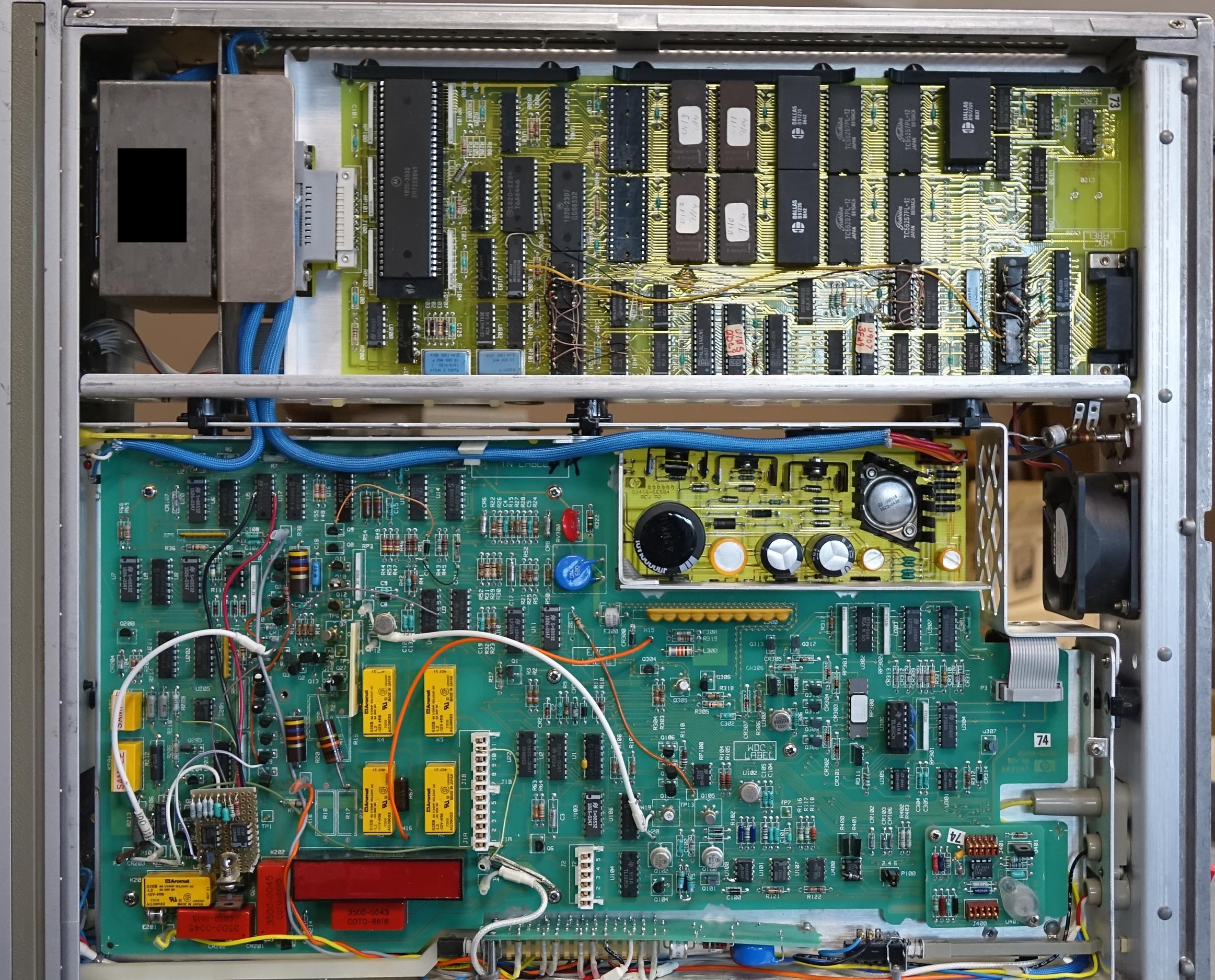
Main processor A5 board is somewhat close to initial production 3458A DIP-chip boards, but have main processor in ZIF-socket, two oscillators and number of dead-bugged logic chips. Interconnect to A6 board has special blade connector, unlike standard 2.54mm pitch pin header we have on current PCBAs. Just like with production processor boards this prototype used same pair of Dallas DS1235 and DS1220 NVRAMs for RAM and calibration ROM data storage.
A4 inguard circuit board use large TO-3 packaged regulator mounted on heatsink and had some additional capacitors. This board is simple enough with just few LDO regulators, so not much other interesting stuff happening here.

Even relays used for current range switching on A1 are marked with “Sample” stickers, hinting for customized or special order relay parts in this prototype. Relays used in production DMMs are DS2E-SL2 type, but perhaps they were just starting to manufacture them back in 1985, as ones on prototype boards don’t even have any labels or part-number marking.
Instead of custom four COTO 0490-1658 reed relays found here we can find more traditional armature high power rated S2EB-L2-12V latching type. However large high-voltage relay COTO 5000-0124 and three low-thermal COTO 3500-0043 are still here. In modern A1 boards same HV reed relay has custom COTO part-number 0490-1657 designated for HPAK. Low thermal relays are marked COTO 0490-1748 on modern A1 PCBA. RoHS 03458-26511 Rev005 PCBA also have same COTO 0490-1748 K1, K3 and COTO 3500-0044 for K4.
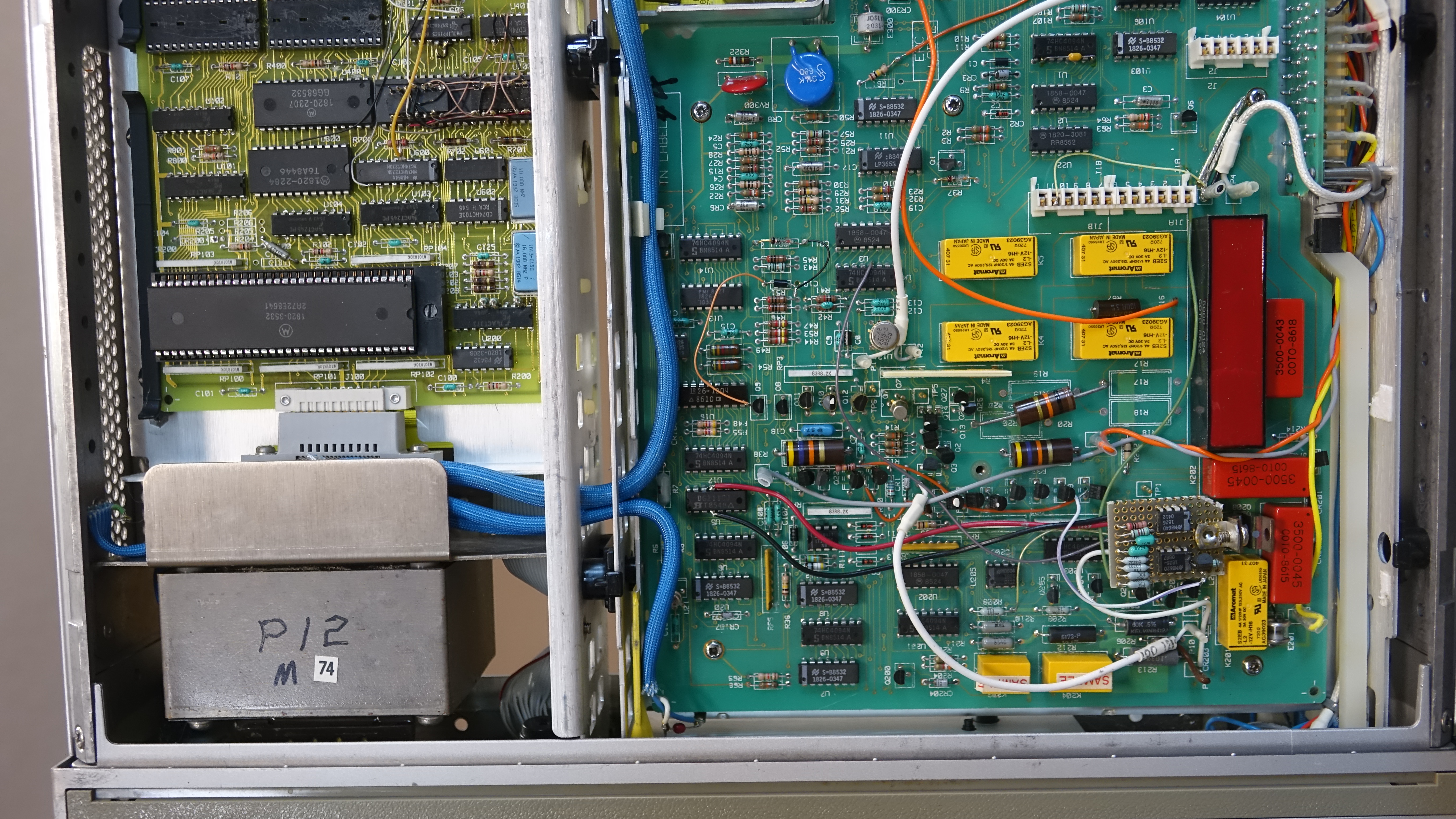
A9 reference module is quite different to modern revision and used cheap 1% film resistors instead of Vishay S102 resistors. Otherwise it’s still original LTZ1000A closely repeating typical datasheet circut design from Linear Technologies.

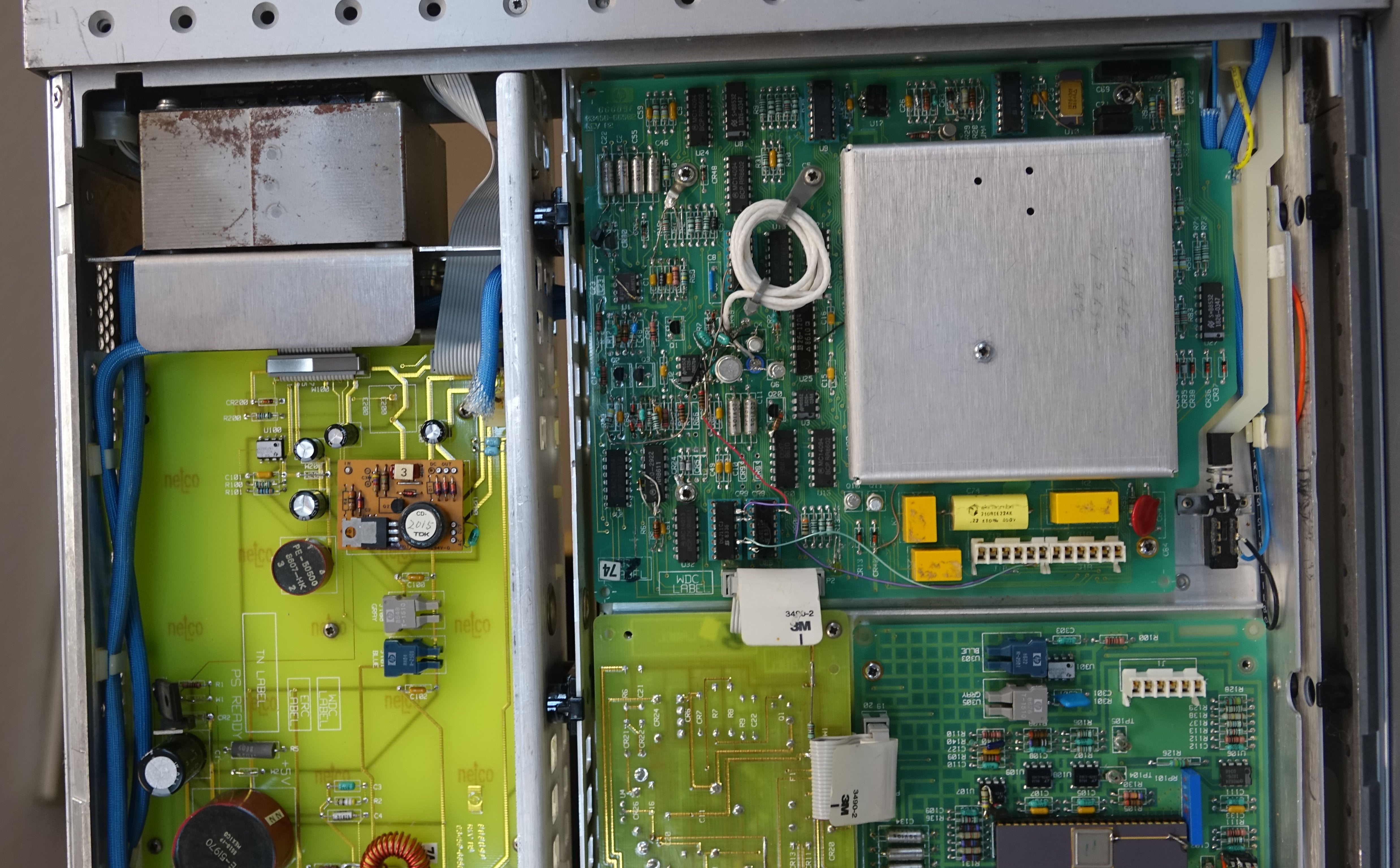
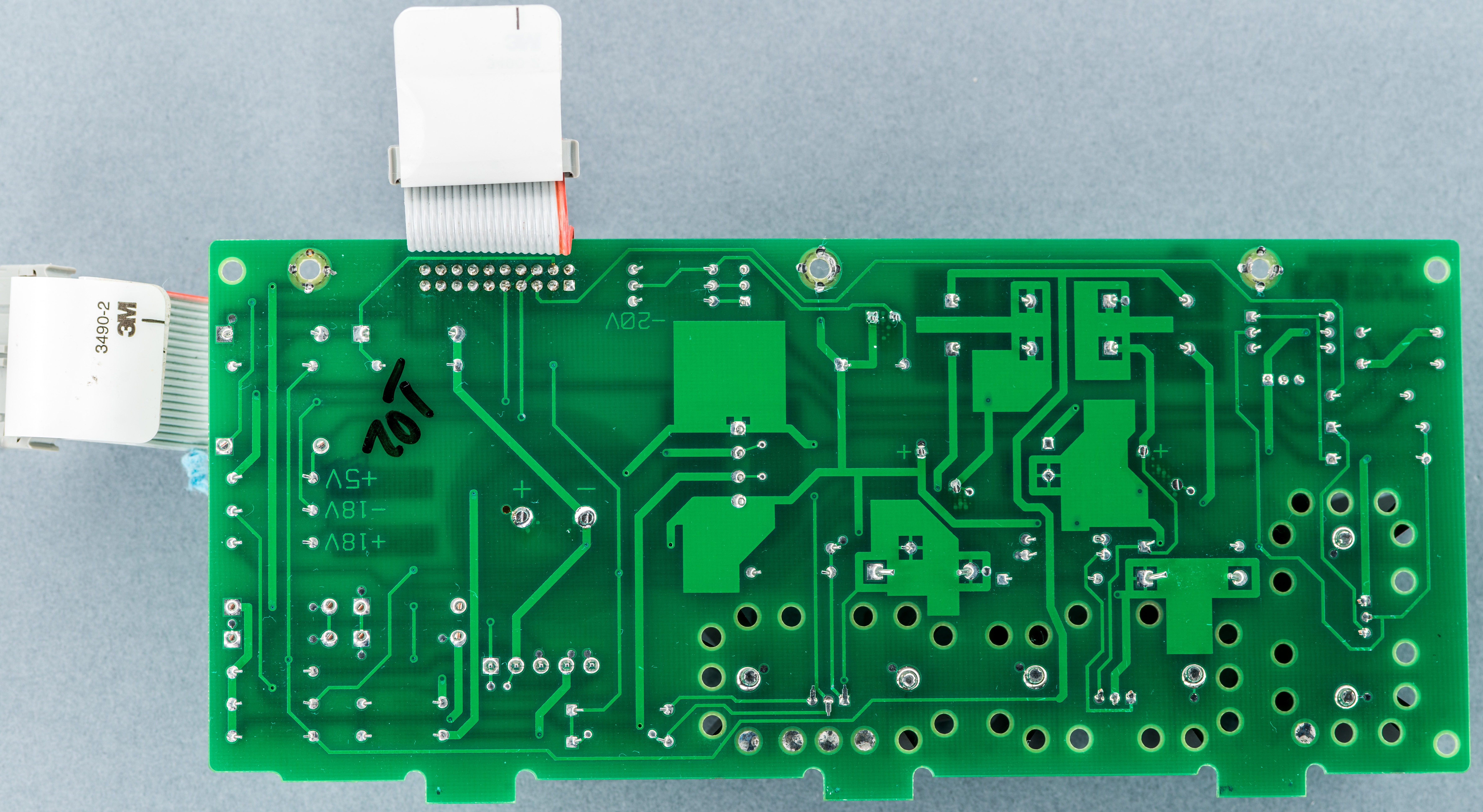
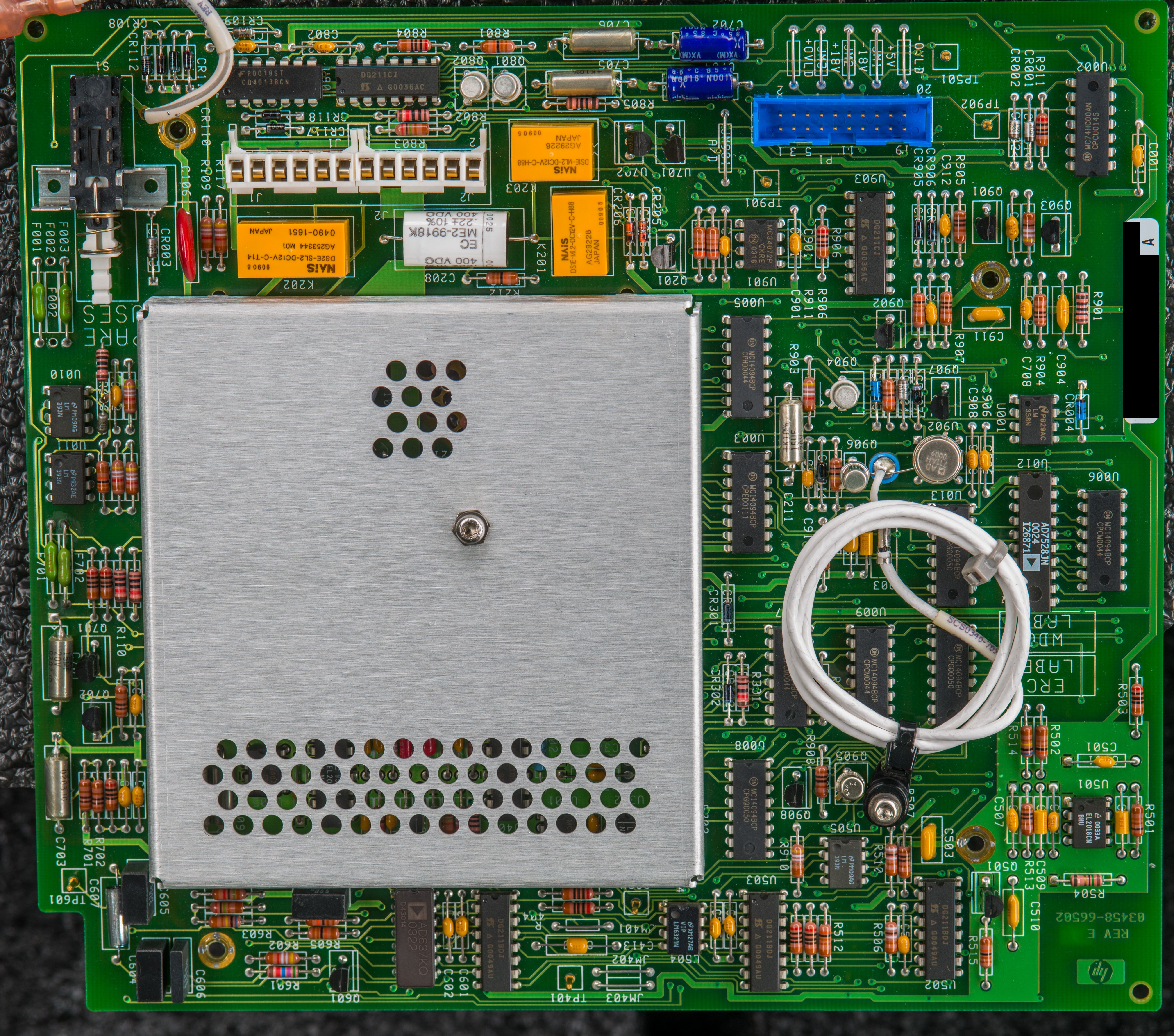
On the bottom side of the instrument we can see most of the difference to modern 3458A hardware. Transformer is different with multiple wires going to all electronic assemblies. A6 outguard power supply board with Revision A5 datecoded with 1986 week 4 and has some parts hanging on the wires. DC +5V regulator have just metal braid instead of modern metal heatsink/bracket mount to chassis. Large bulk capacitor with smaller 6800 µF x 35VDC rating is radial type around the board center. Location of IEC mains input power filter and 110/230VAC switches is different too. Front panel electronics is placed on front panel board, and not on A6 in this prototype unit. DC/AC module to supply VFD with filament and high voltage is same as production units.

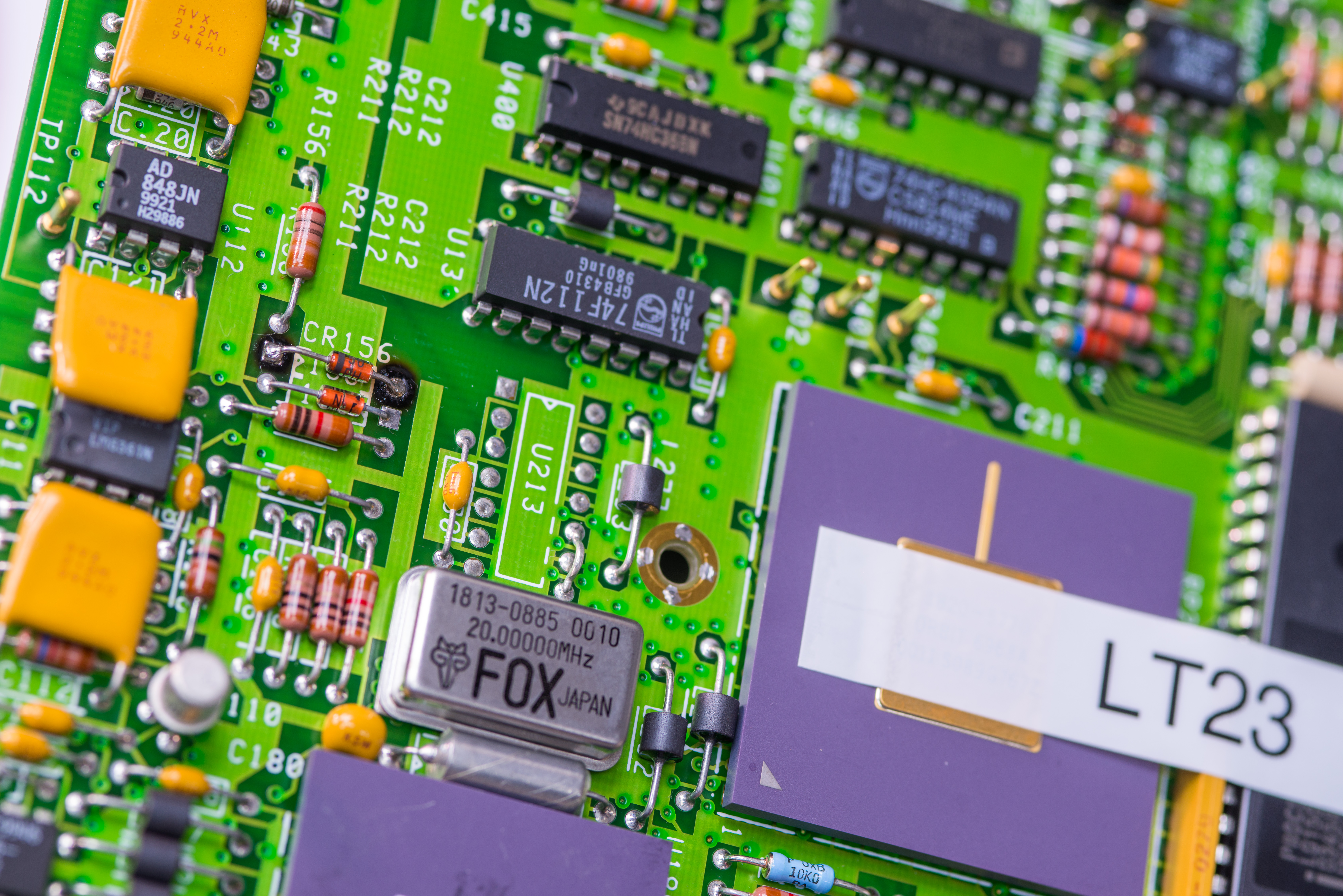
Famous A3 A/D board from 1986 week 44 have very different U180 hybrid chip in ceramic CDIP48 package, installed in socket. It is actually even has different part designator U111. This was due to use of much smaller less stable resistance elements together with active FET-switch die. Later this hybrid chip design was improved and changed into U180 we know today with larger separate chip resistor network placed in much larger ceramic square PGA package.

Analog A/D reference voltages +12, -12 and +5V on this old A3 board were generated same way with external LT1001 opamps U108, U109 and U107. There are some bodges with resistors and JFETs soldered onto the parts here and there, showing it was work in progress. Key integrating capacitor C102 is much larger film type in blue epoxy package. In modern boards integrating capacitor is just small ceramic MLCC type. Also instead of Elantec EL2016 comparator here we can find LT1016 with designator U110 instead in the board corner.

Gate array chip on prototype board by japanese manufacturer Fujitsu has P/N MB651305 and placed on a blue socket. It’s cool to see ES mark on the gate array PGA package, meaning it is still “Engineering Sample” grade part. Clock source for A3 operation is 20 MHz RASCO 1 oscillator manufactured by Motorola in week 14, year 1986. In-guard microcontroller manufactured by Intel P/N L8360206 also in pretty CERDIP40 package with transparent glass window to allow UV-erase for firmware updates. There is also dead-bugged DIP14 chip with some wires next to MCU, perhaps just some glue logic to handle digital control signals.
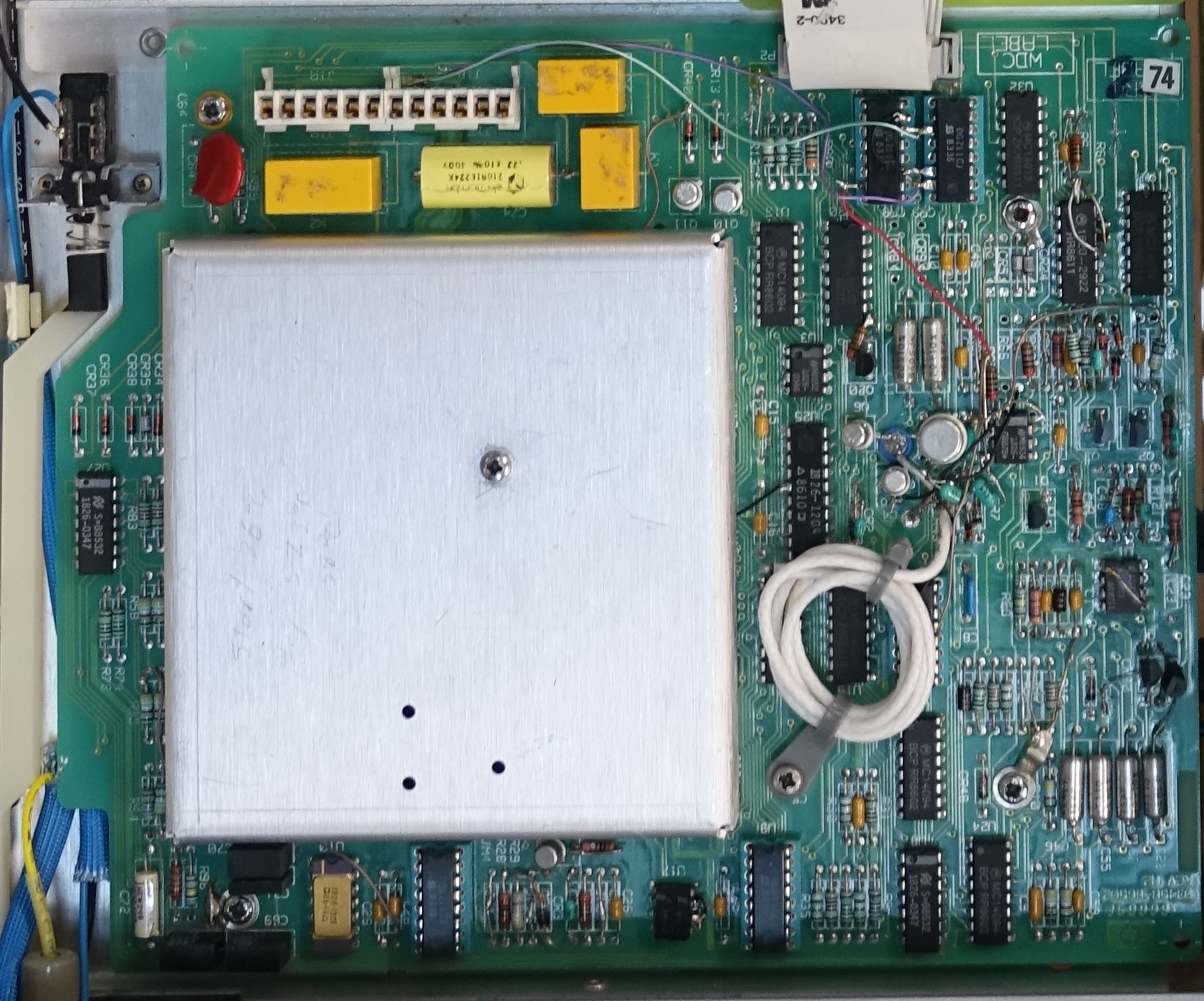
AC board also have number of test jump-wires and circuit patches, unmarked DS2E-type relays. Guard switch is mounted to chassis instead of PCB. Voltage regulators for this board was generated on elsewhere instead of local like its done now in production 3458A. That perhaps explains additional LDO on A4.
Notable capacitor build from piece of PTFE-insulated coax wire is already in place on prototype board here. Overall this old A2 board looks less busy than modern production, perhaps with smaller AC voltage functionality set in EP74 3458A unit.
Sourcing missing components
TBD
Bad PCBAs repairs
TBD
A6 PCBA Out-guard power supply
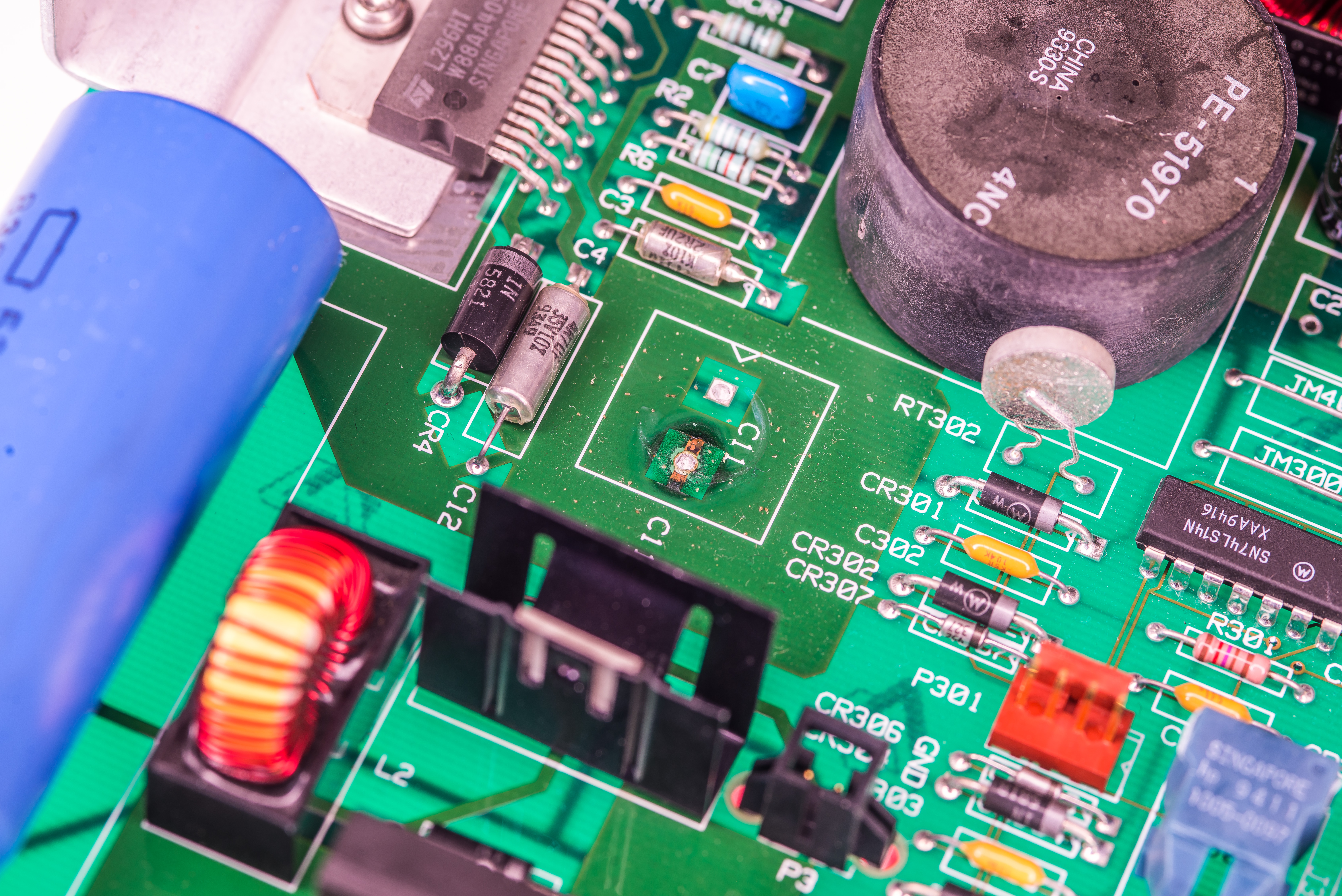
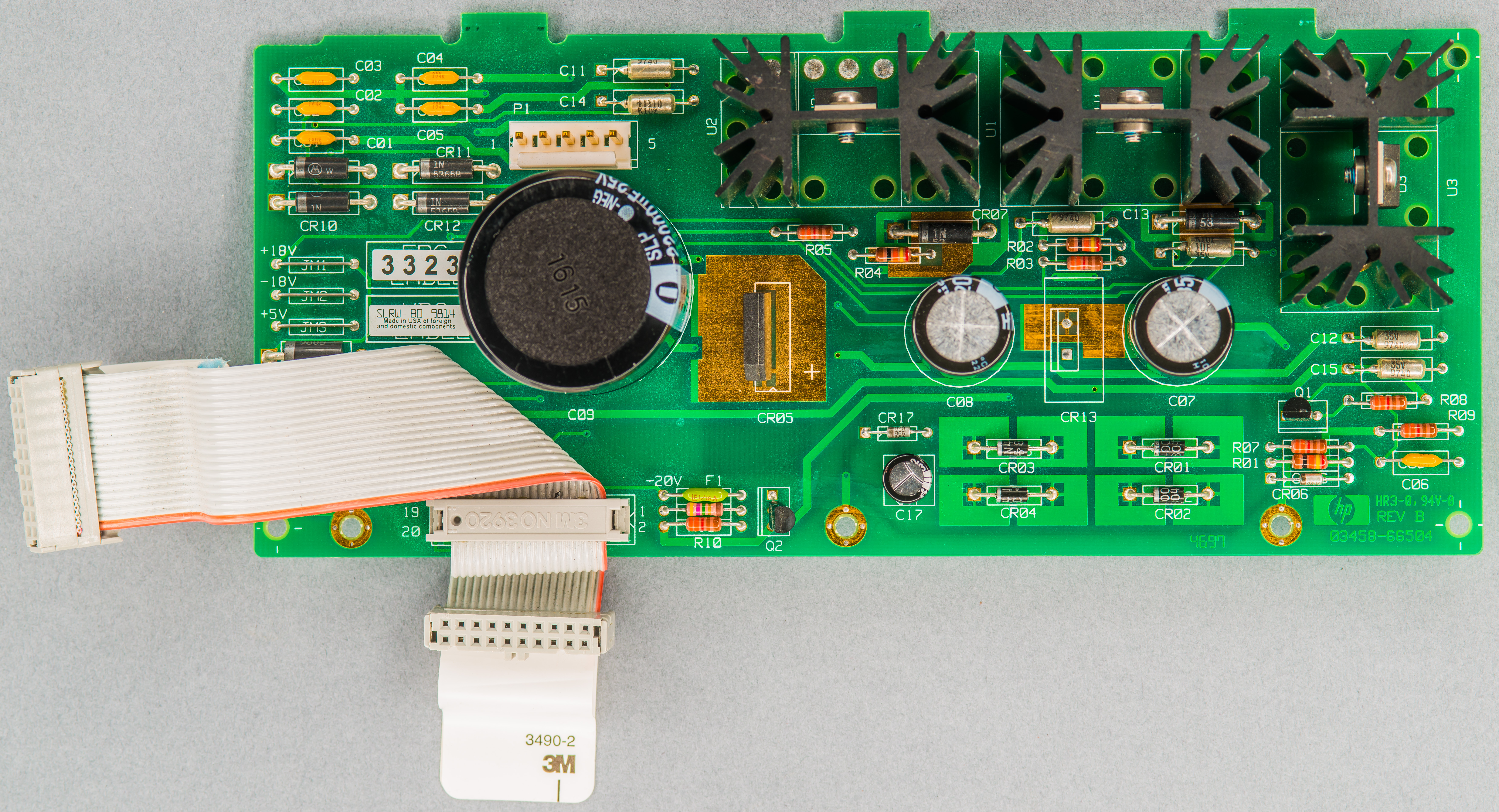
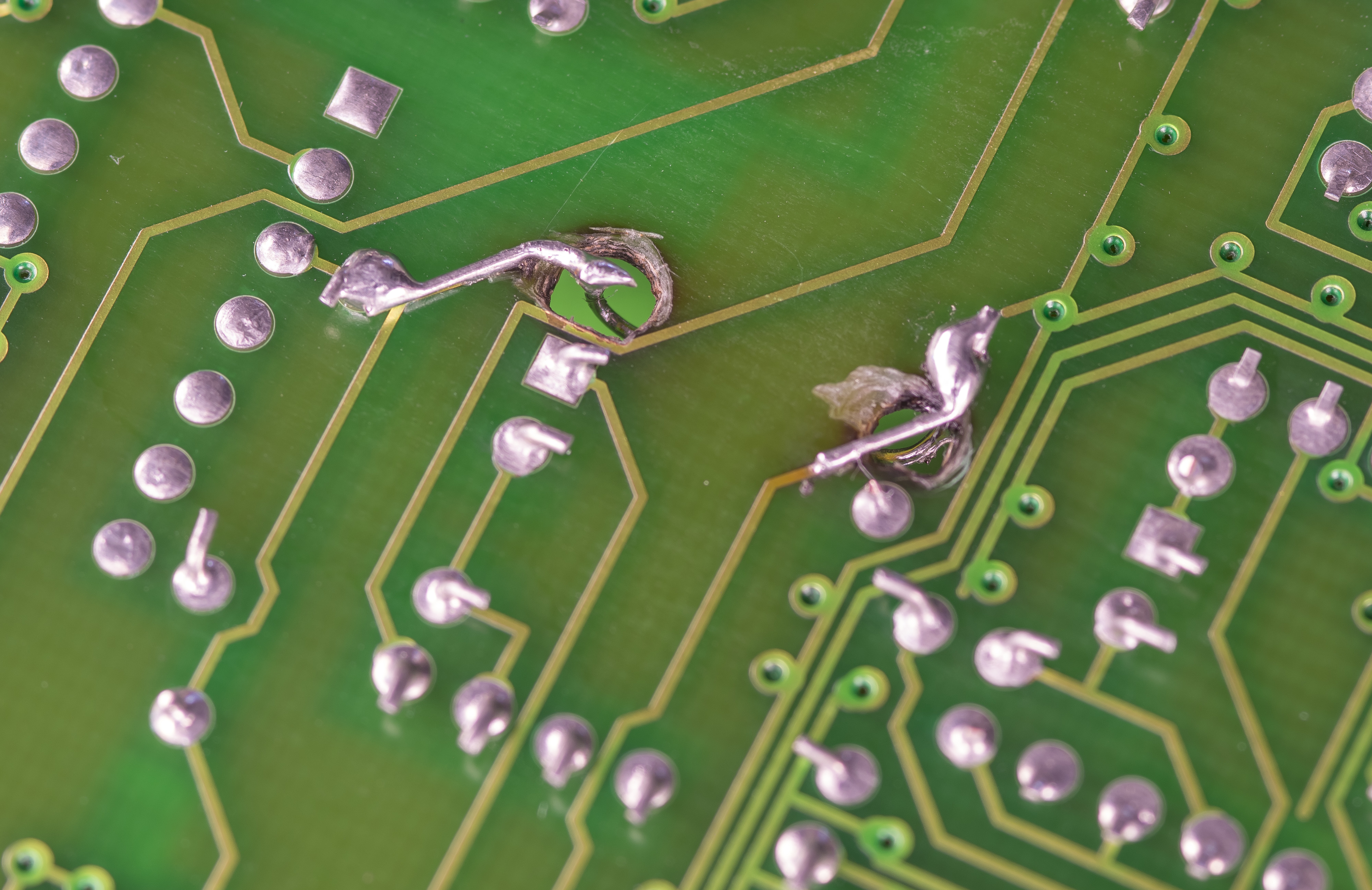
With A6 installed and connected to transformer I got no power to CPU board or display. After sniff tests and poking around the culprit was quickly discovered. L2 filter inductor next to large blue axial capacitor had broken pin and no contact to actual PCB.
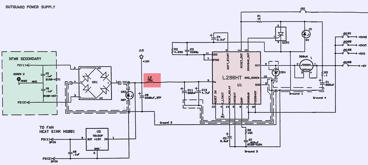
And since this inductor was at the input of main +5VDC regulator, nothing else on A6 board was getting power.
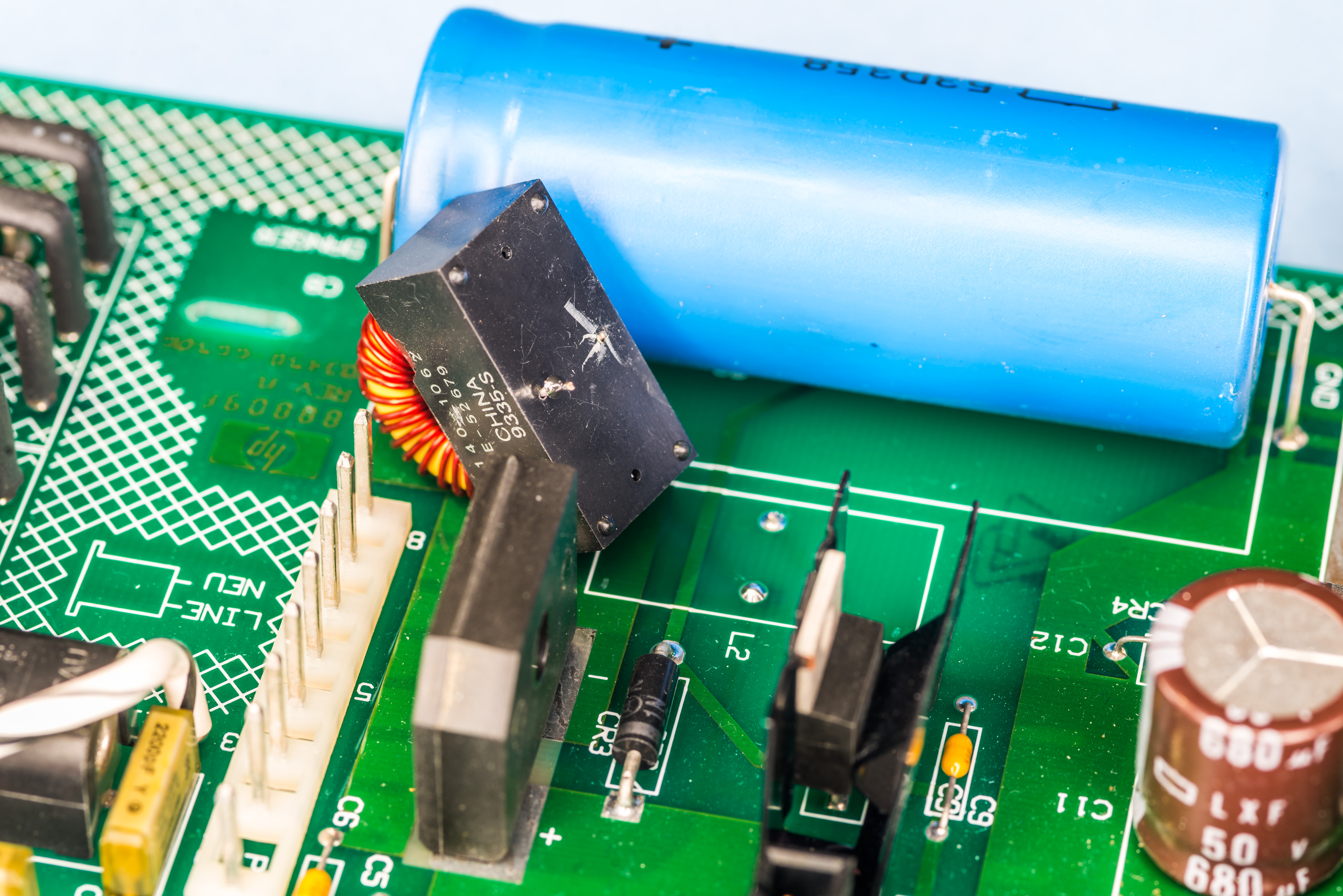
Fixing was simple removing some of the plastic to get access to pin remains, soldering extension pin and populating this contraption on the PCB. In future I’ll replace the whole inductor with a new one, but for now this will work.
And since we are at it, let’s replace old electrolytic caps on A6 PCBA as well.
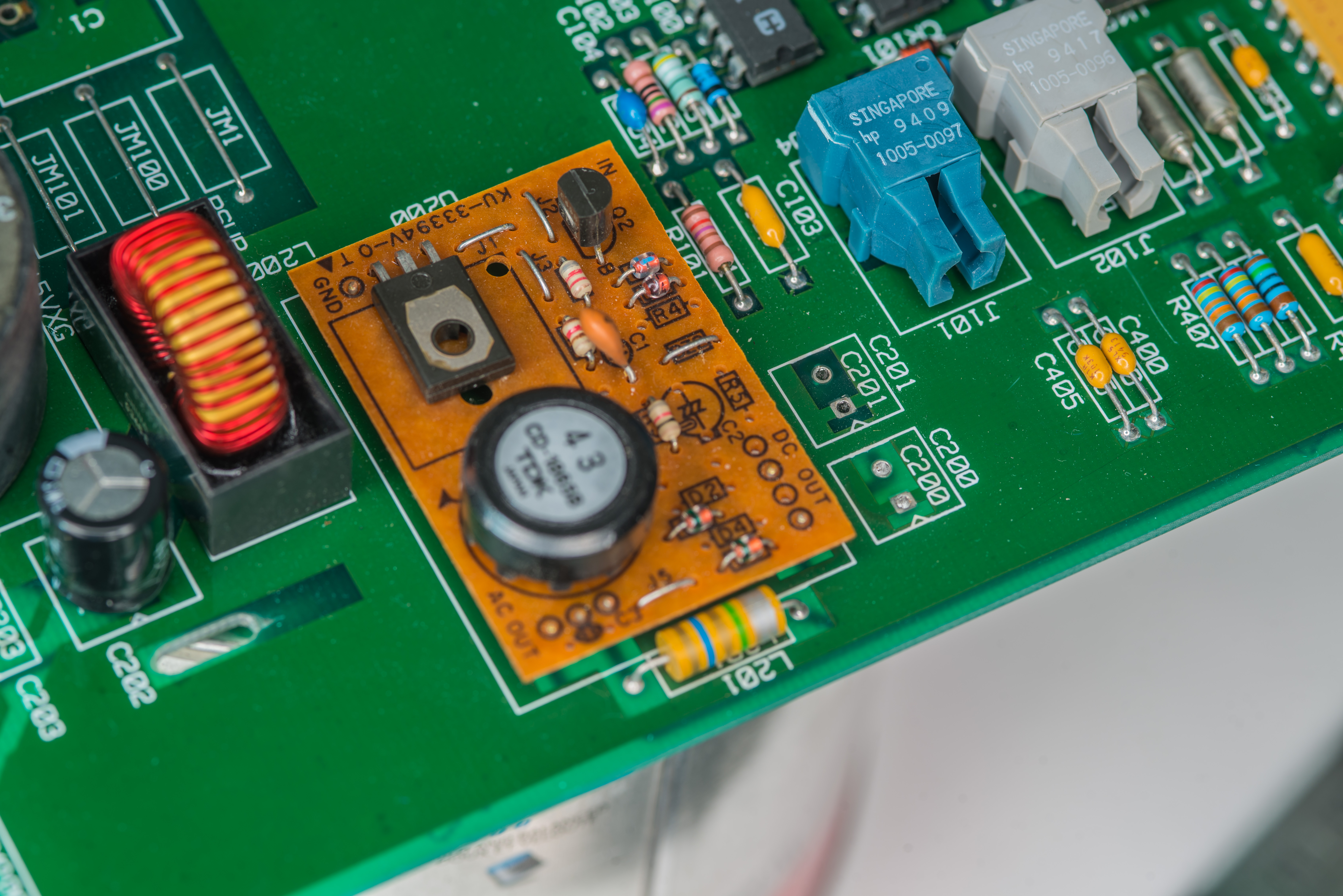
A quick look and on DC-AC module to generate power to vacuum fluorescent display on front panel. There are two 47 µF 63VDC rated caps and two 220 and 330 µF; capacitors at the input.
Two larger 680 µF 50V capacitors C1 and C11 already started their dirty business with leaking electrolyte. PCB solder mask started to flake near one of the pins. It’s good idea to replace old caps and clean up damaged PCB on old HP instruments, even when externally everything still looks fine and instrument working properly. Don’t delay, replace your capacitors today. :)

Negative pin on C11 position suffered more noticeable damage, perhaps because it was closer to warm regulator nearby.
I didn’t have good replacement in stock at the moment, so for now installed 1100 µF 50V and 820 µF 50V capacitors in C1 and C11 place. Later we can install better sized capacitors here.

Board is now ready for tests and should be working fine.
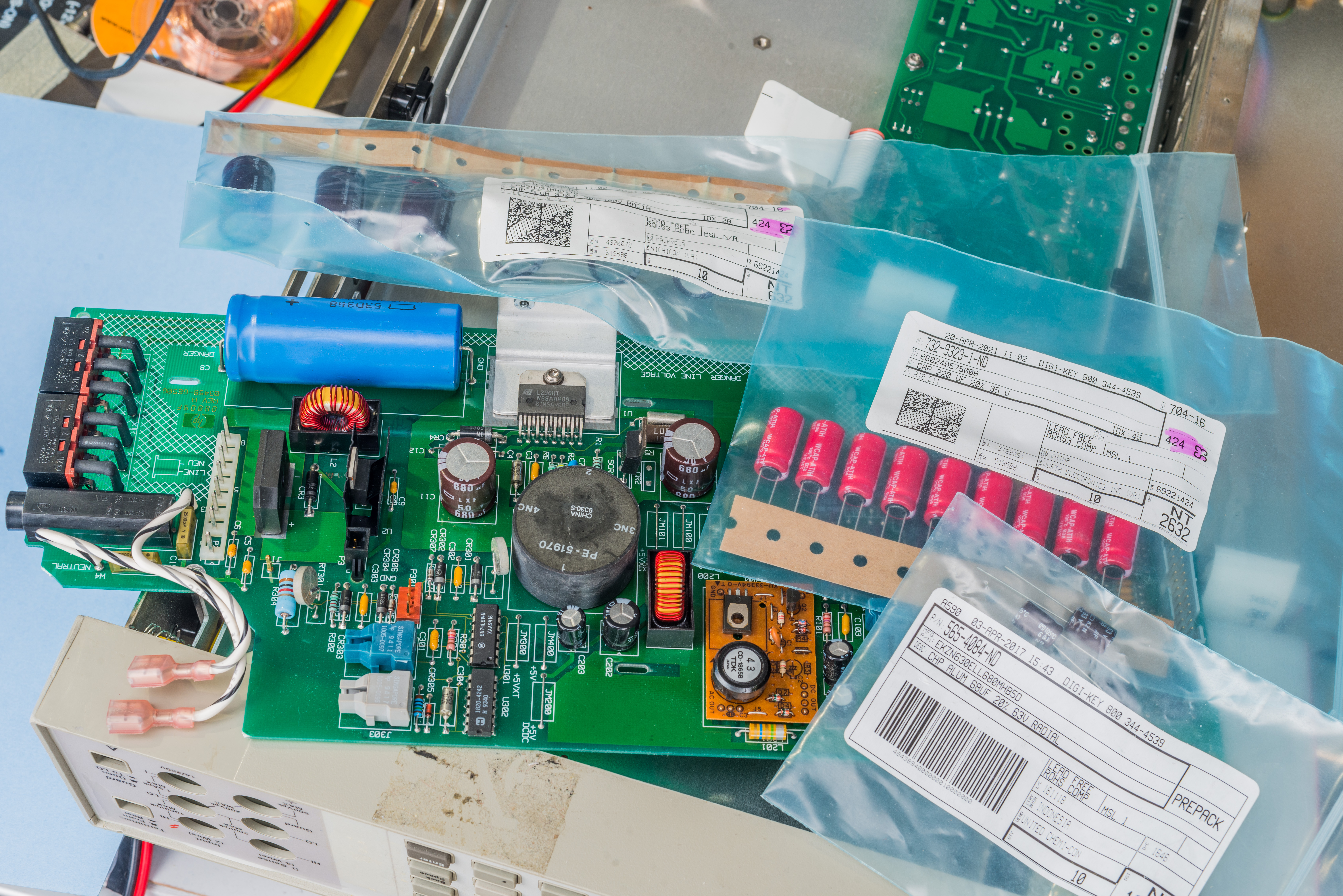
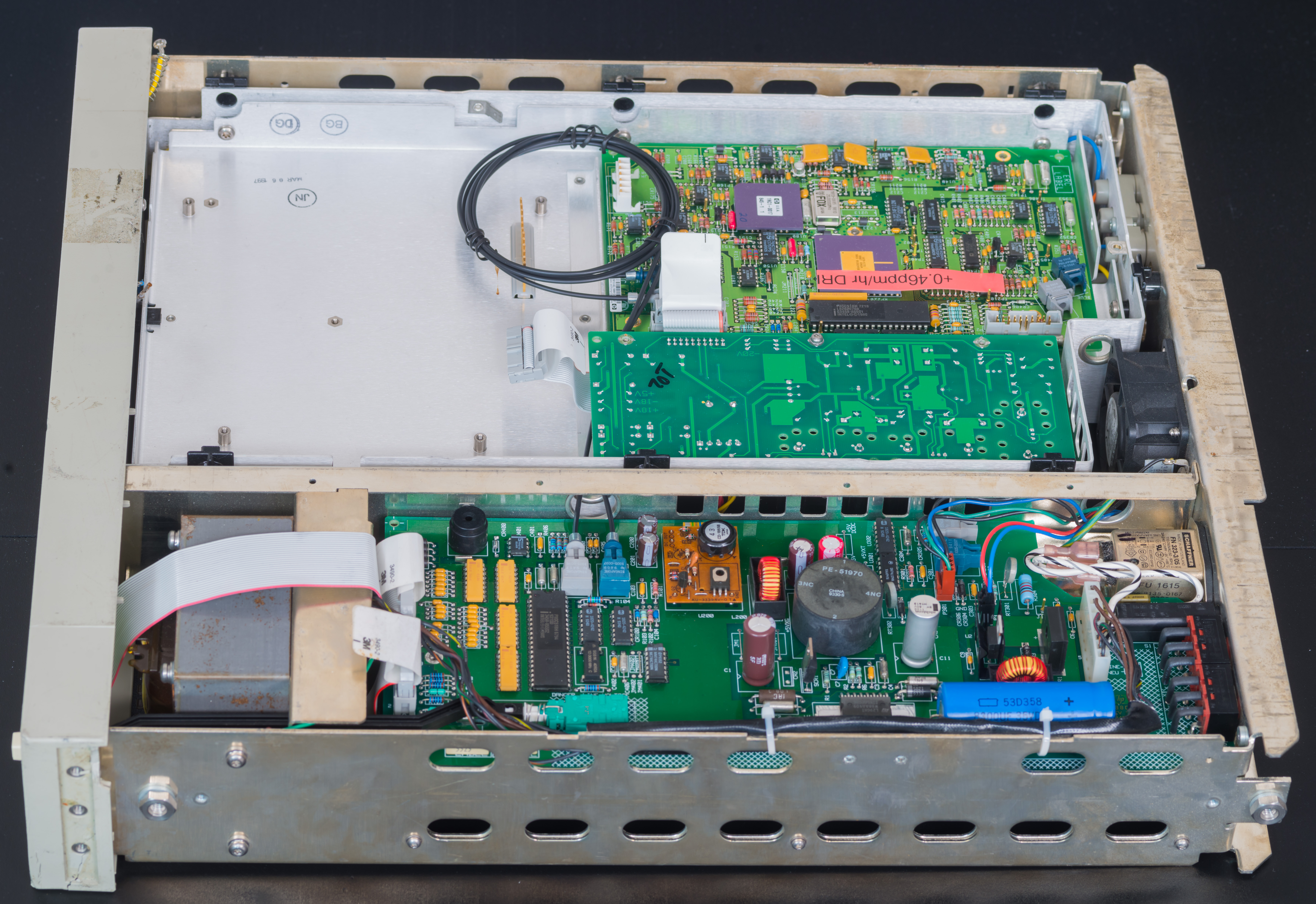
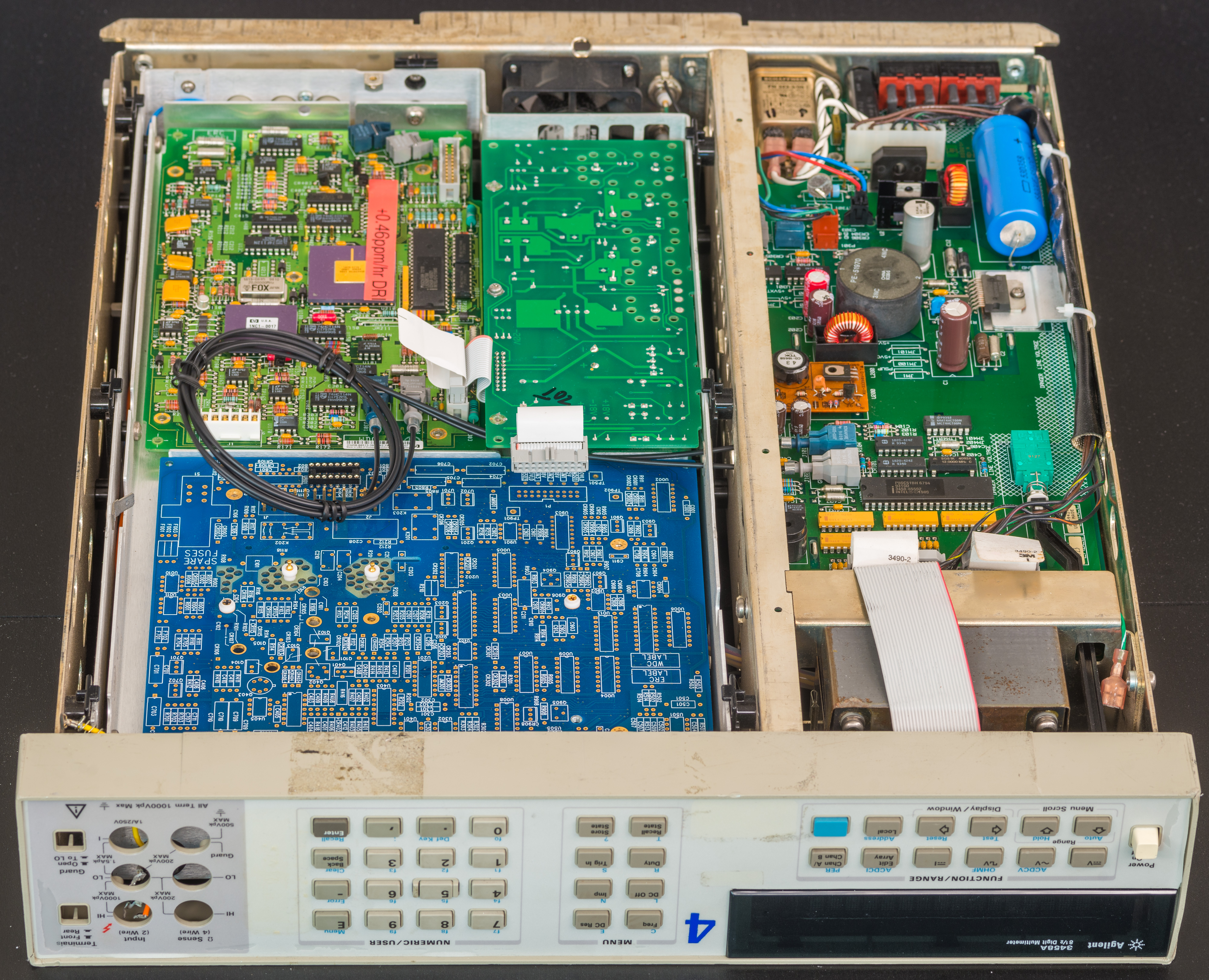
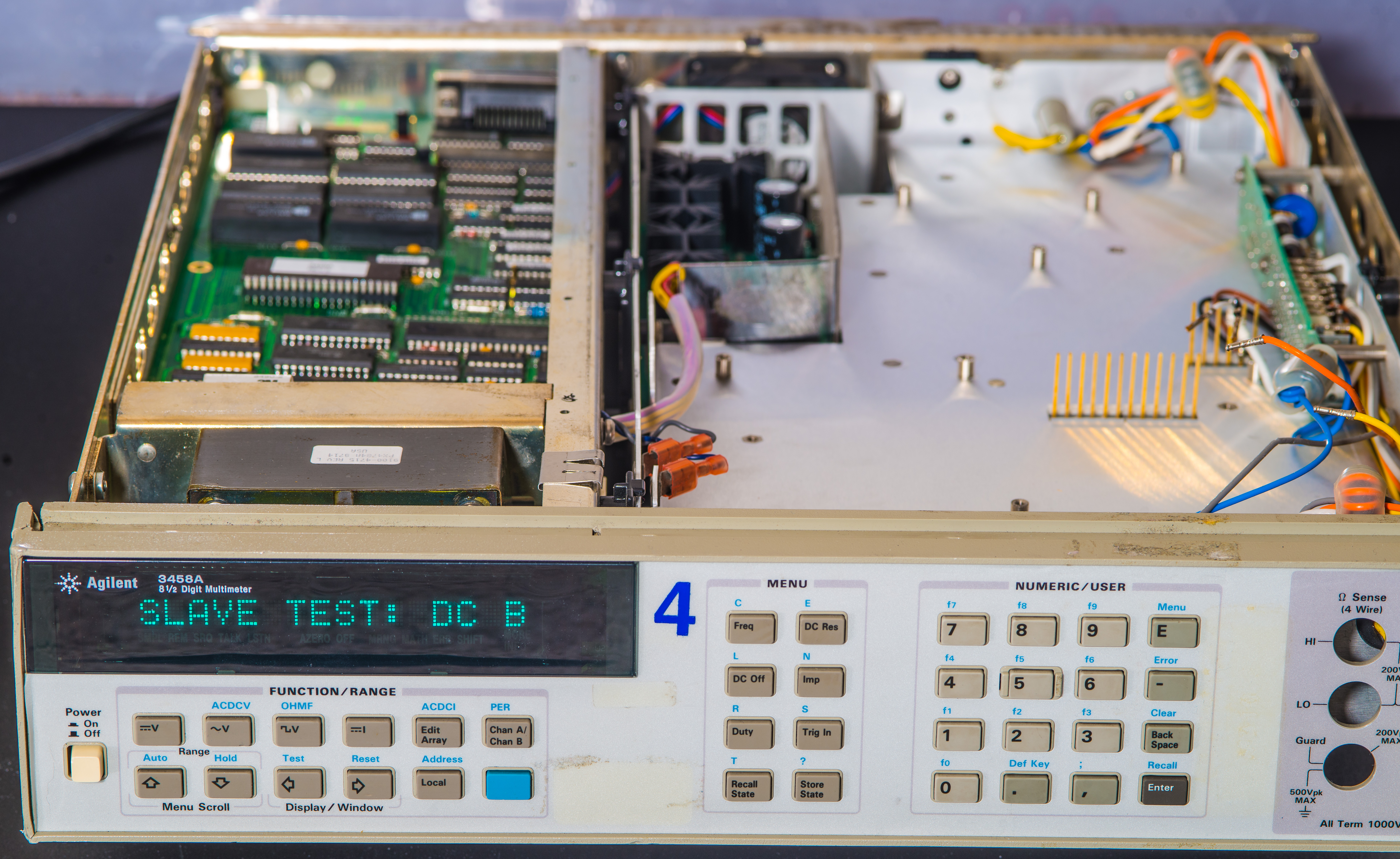
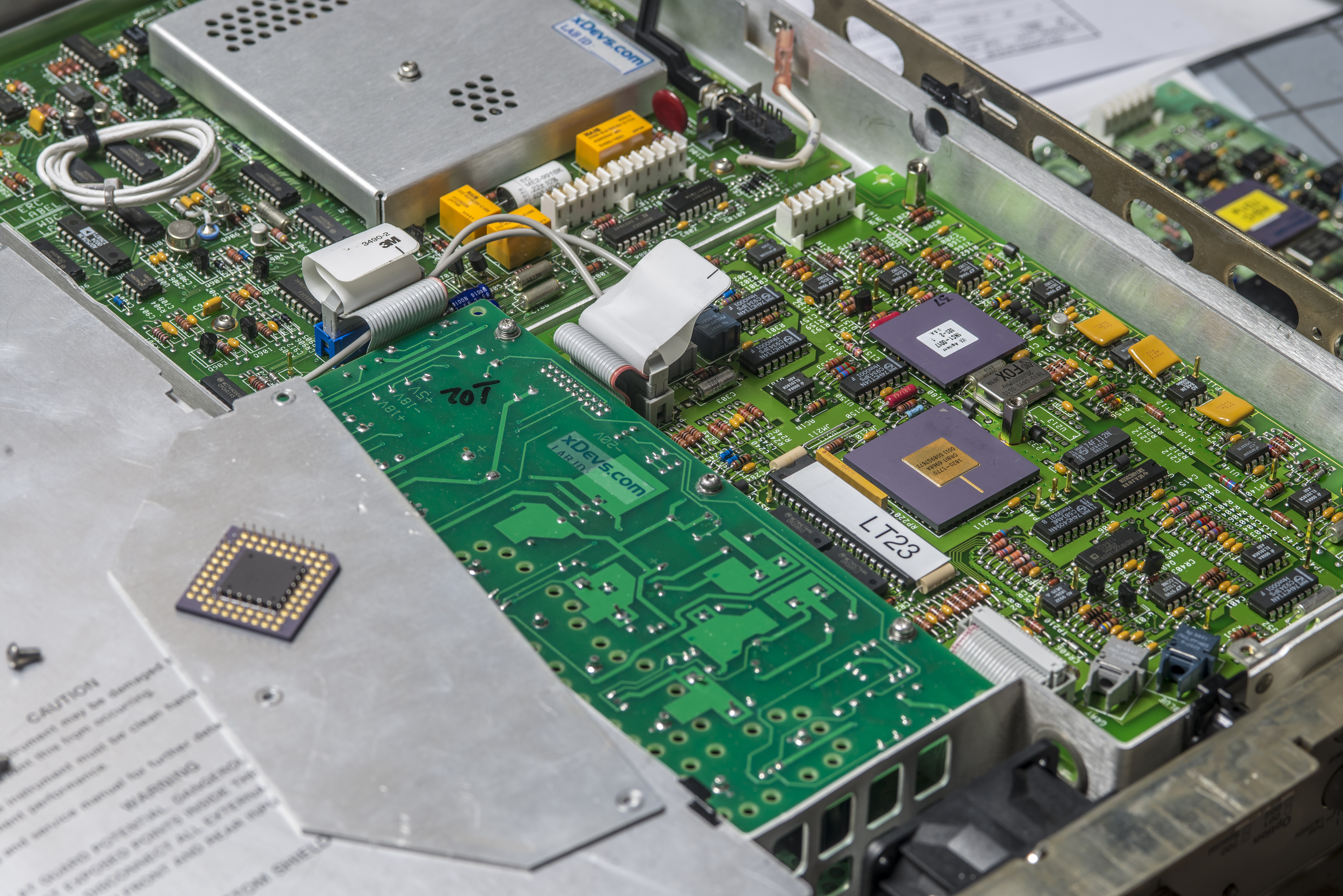
First power-on with A4, A5, A6, front panel and bad A3 board installed in chassis.
After quick check 3458A powered up and CPU board greeted us with first messages on display. Obviously we’ll get ISOLATOR FAILURE without any inguard electronics. So A4 and broken (drifty U180 hybrid) A3 were installed to poke around some more.

A4 inguard power supply board was tested and confirmed working, with good +5 VDC, -20V, +18V and -18VDC outputs. I don’t have original HP fiber, so here everything connected with aftermarket much longer fiber cable between A3 A/D converter board and A6 outguard power supply/guard crossing interface board.
Don’t have A2 board yet, so it is still part to source later on. 3458A would NOT operate even in DCV-only function if the A2 AC board is missing. There are some communication and signals going between A1 DC board, A2 AC board and A3 A/D converter, so all of these need to be working to allow even simplest DCV measurement from the instrument. Otherwise firmware is upset and will not give you any readings.
It is possible to build DIY-version A2 PCBA, populating whole A2 assembly with parts on aftermarket copy of original PCB layout. But I’d expect many of the original spec components be obsoleted and expensive to acquire today, so perhaps we keep that idea for Plan B, when it comes to that.
Without A1 board installed meter boots up and after quick RAM/ROM TEST goes to major fault 202, HARDWARE FAILURE: DC BOARD. So next step is getting A1 into the instrument.
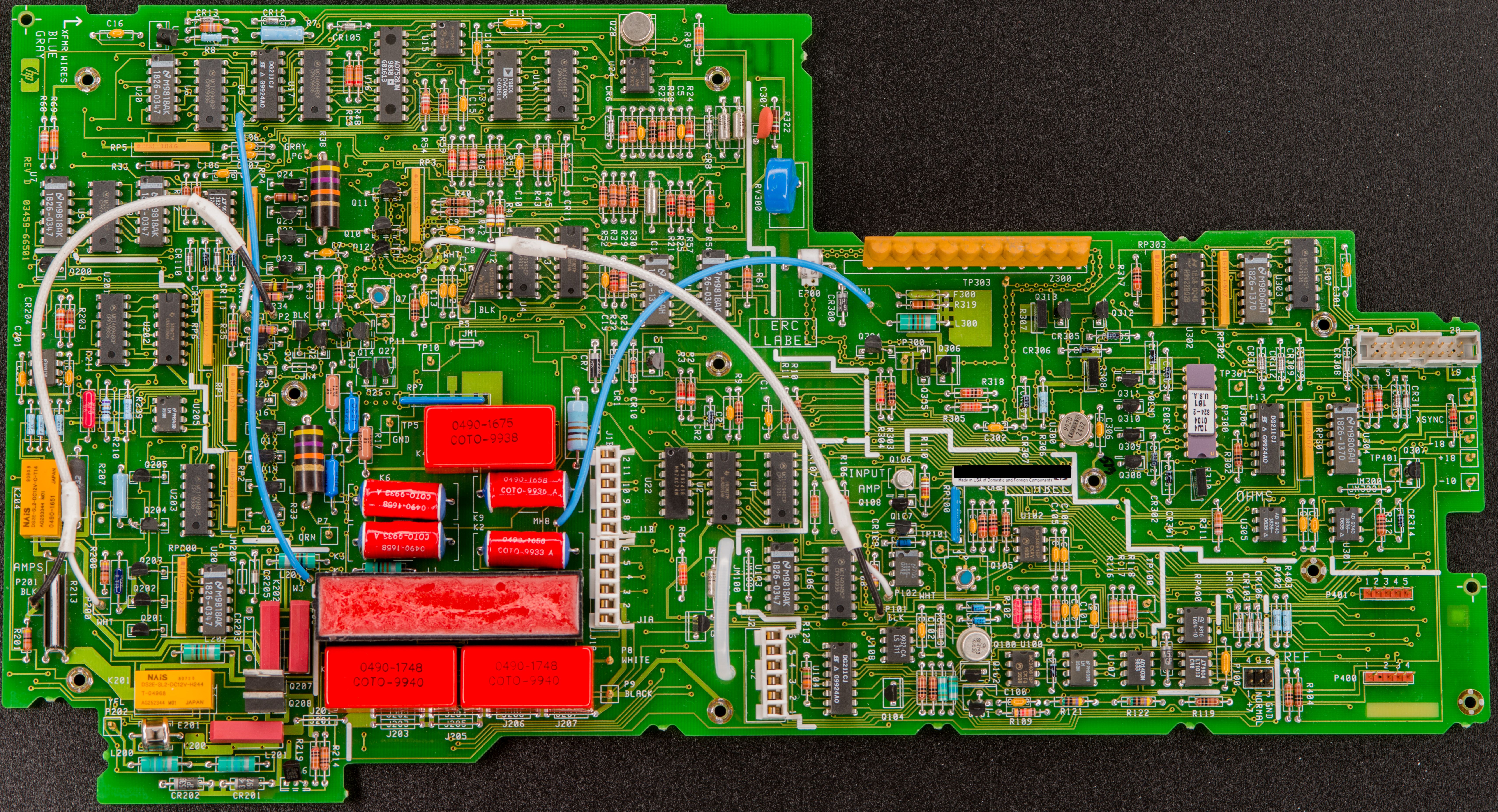
03458-66501 Rev.D A1 DC analog board repairs and tests
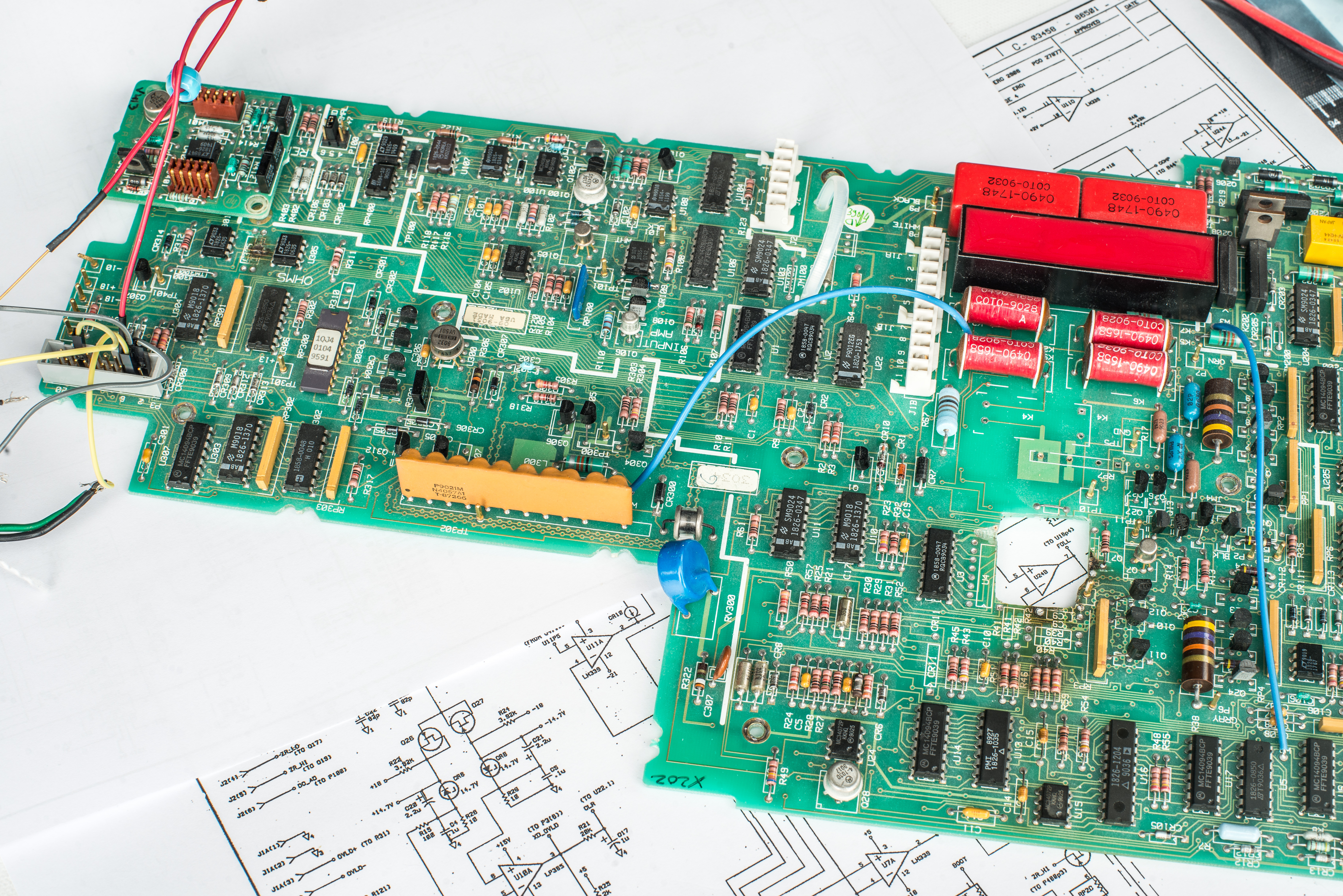
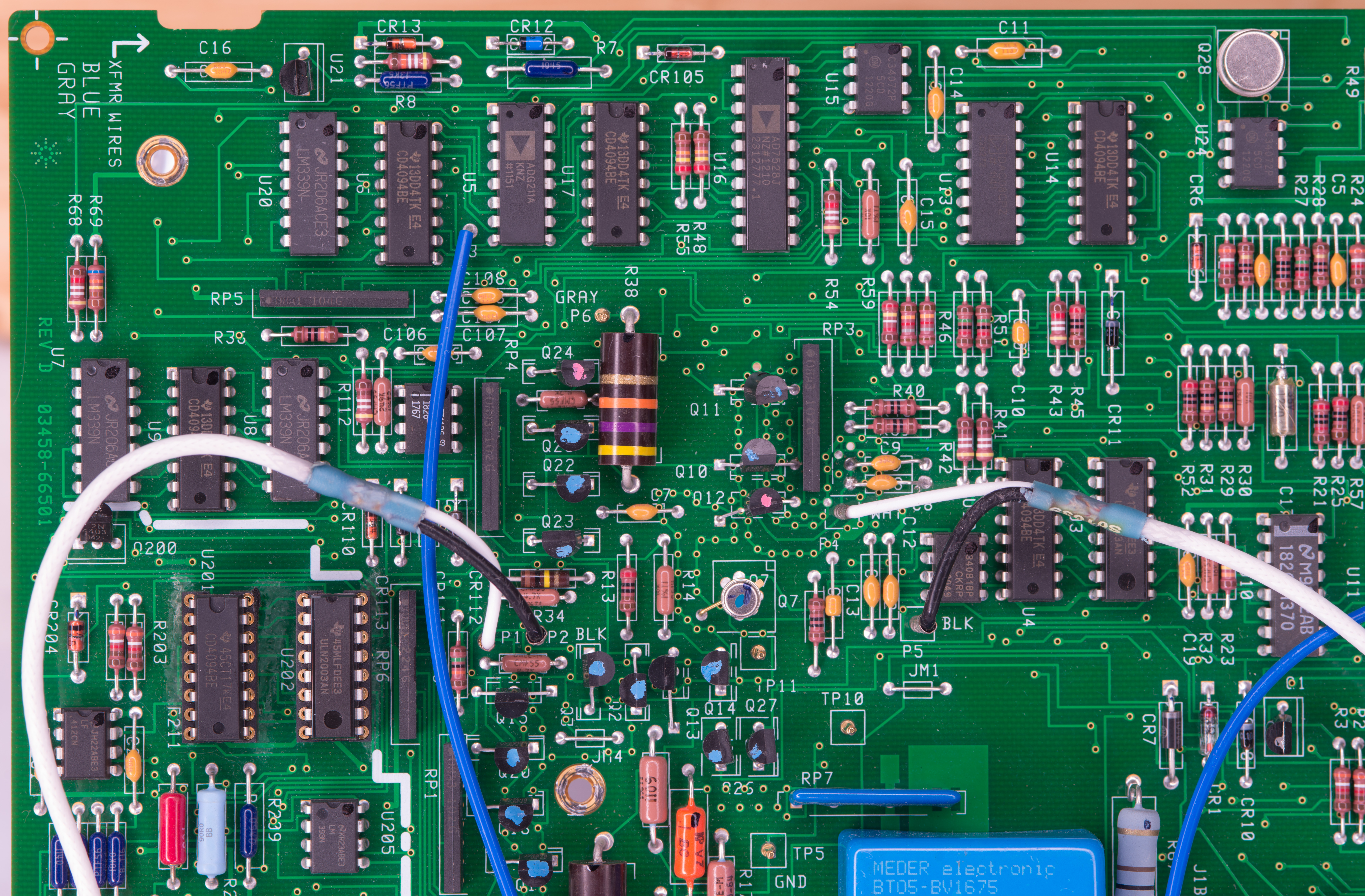
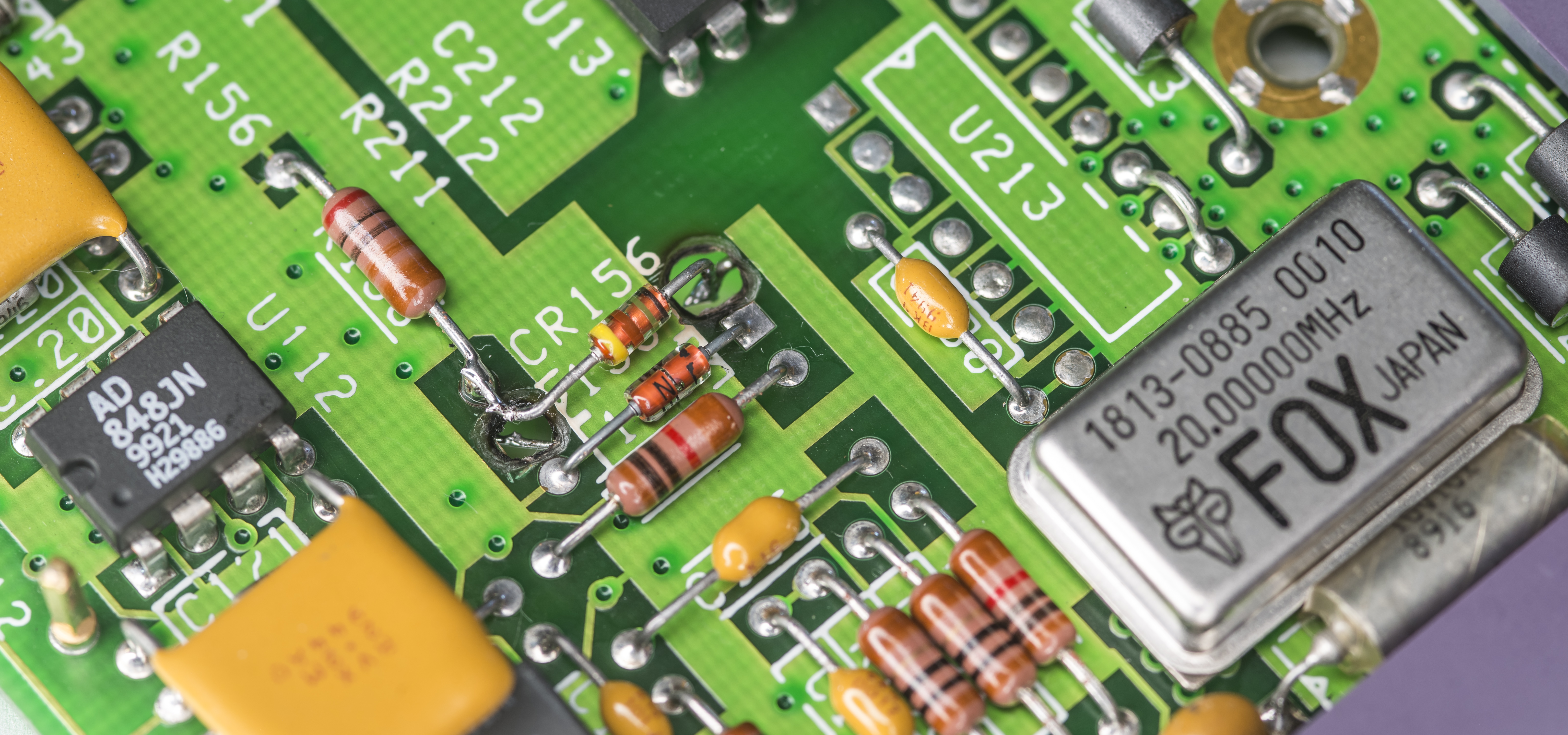
How that we are done with easy stuff and power supplies are working, time to get to real difficulties in the repairs. I have here one poorly handled A1 DC PCB, donated by long-time supported of xDevs.com project Todd. It had blown chip right in the middle, which I’ve cut out years ago with dremel. Also board is missing some of special components like shunts, high voltage resistor divider network and other minor parts used in other projects. We’ll need to put missing parts back in to make it fully function. And fix everything wrong with this board otherwise, so it might be a deep rabbit-hole here with this one.
This A1 PCBA had few MLCC decoupling caps catch fire, so perhaps suffered major overvoltage on power rails. Hole in board can be repaired with specially designed patch PCB that would restore missing connections and parts back in place.
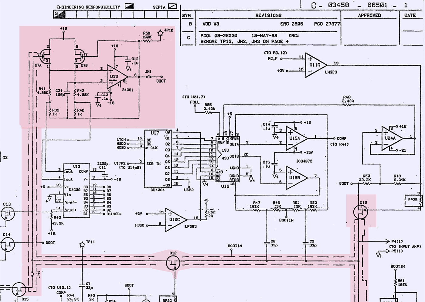
Estimated dead parts are bootstrap amplifier/driver U12, related Q7 dual JFET transistor array and bunch of passives around the affected area. I’d think JFETs connected to sensitive node at Q7 input likely destroyed too, despite visually undamaged condition.
U3 and U4 are also were in the blast zone, so these will need to be repaired as well.
Perhaps before I connect this board to actual meter power supplies it would be better idea to power it from laboratory power supply and see if anything heats/cooks abnormally. If there are any parts that shorting power rails, we’d see it right away from excessive power draw and heat. This way there is no risk to kill good power supplies and transformer in 3458A we repairing.
To test this I’ll use quad-output HP 6629A power supply together with Keithley 2400 and Keithley 2425 Keithley SourceMeasure units. A1 board needs +5 VDC, +18 VDC, -18 VDC and -21 VDC power rails to operate.
First power up with lab power supply to A1 PCBA
Laboratory power supply connected to A1’s P3 input with provided +18, -18 and +5 VDC rails. This will allow to check if anything horribly wrong with board, before installing it into actual 3458 frame.
Connections are temporary, so just hacked the temporary adapter wiring from Agilent 6629A to 2.54mm pitch pin header. Red wire cable comes from Keithley 2400 to supply -21 VDC rail.
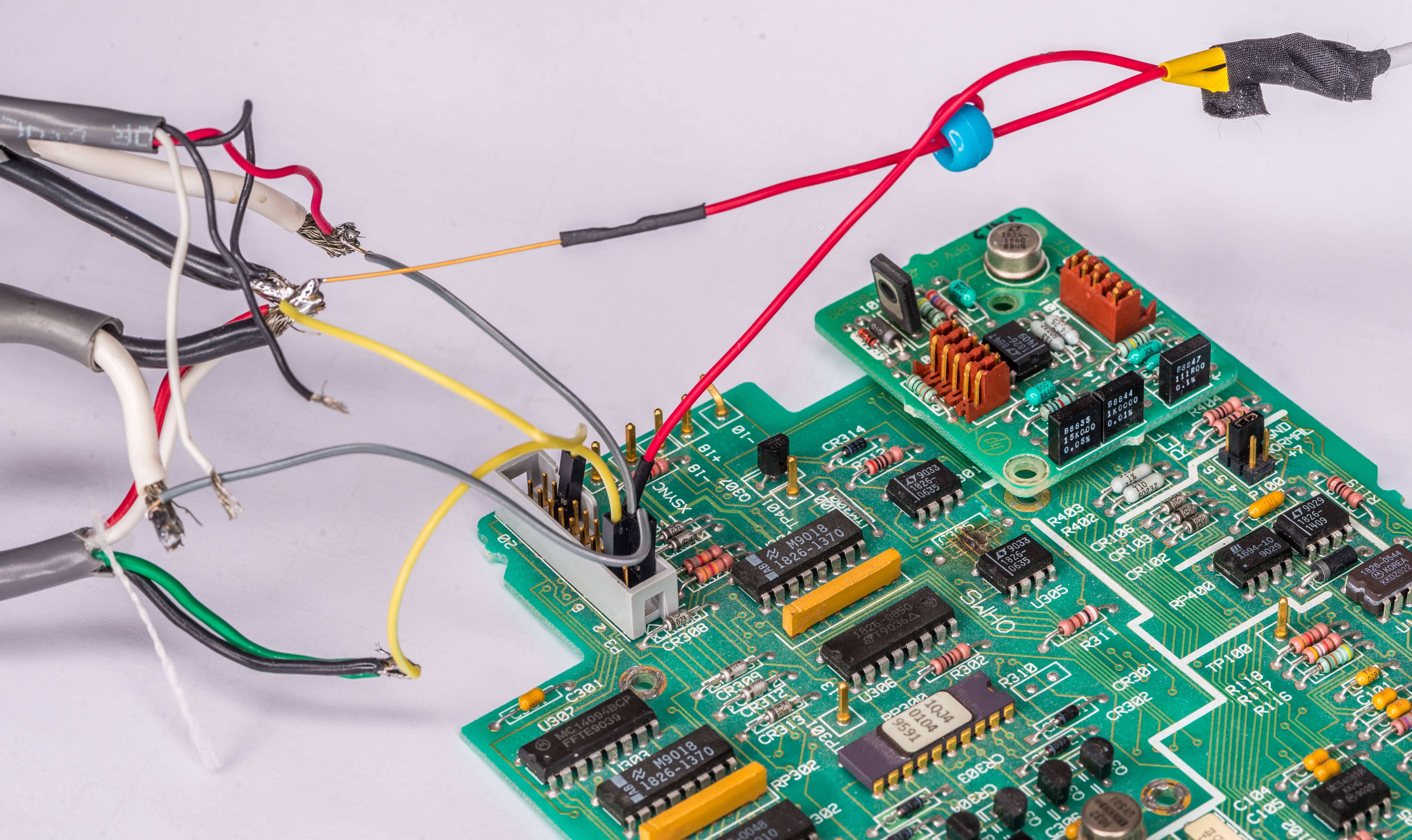
First attempt caused reed relay to click and shows power draw as outlined in table below.
| Power rail | Voltage from PSU | Draw |
|---|---|---|
| +5 VDC | +5.20 VDC | 0.29 A |
| +18 VDC | +18.20 VDC | 0.09 A |
| -18 VDC | +18.20 VDC | 0.05 A |
| -21 VDC | +21.00 VDC | 0.01 A |
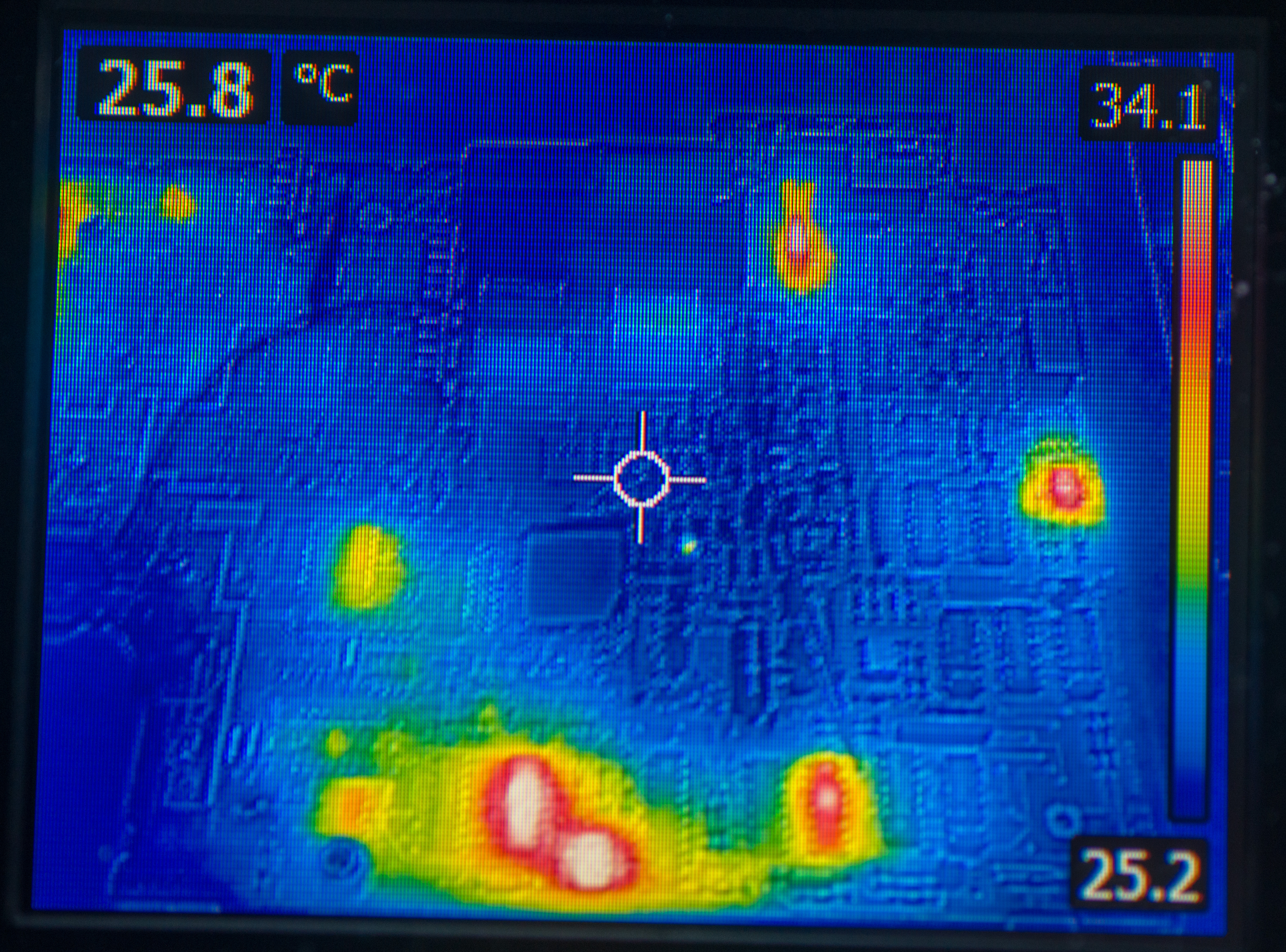
Current compliance limit was set at 0.5 A on each rail, except -21V which was limited to 0.1 A. Nothing heated out of normal and no smokes were observed. Now I’ve installed random A9 DC Voltage reference board to see if we have good zener voltage output for A3.

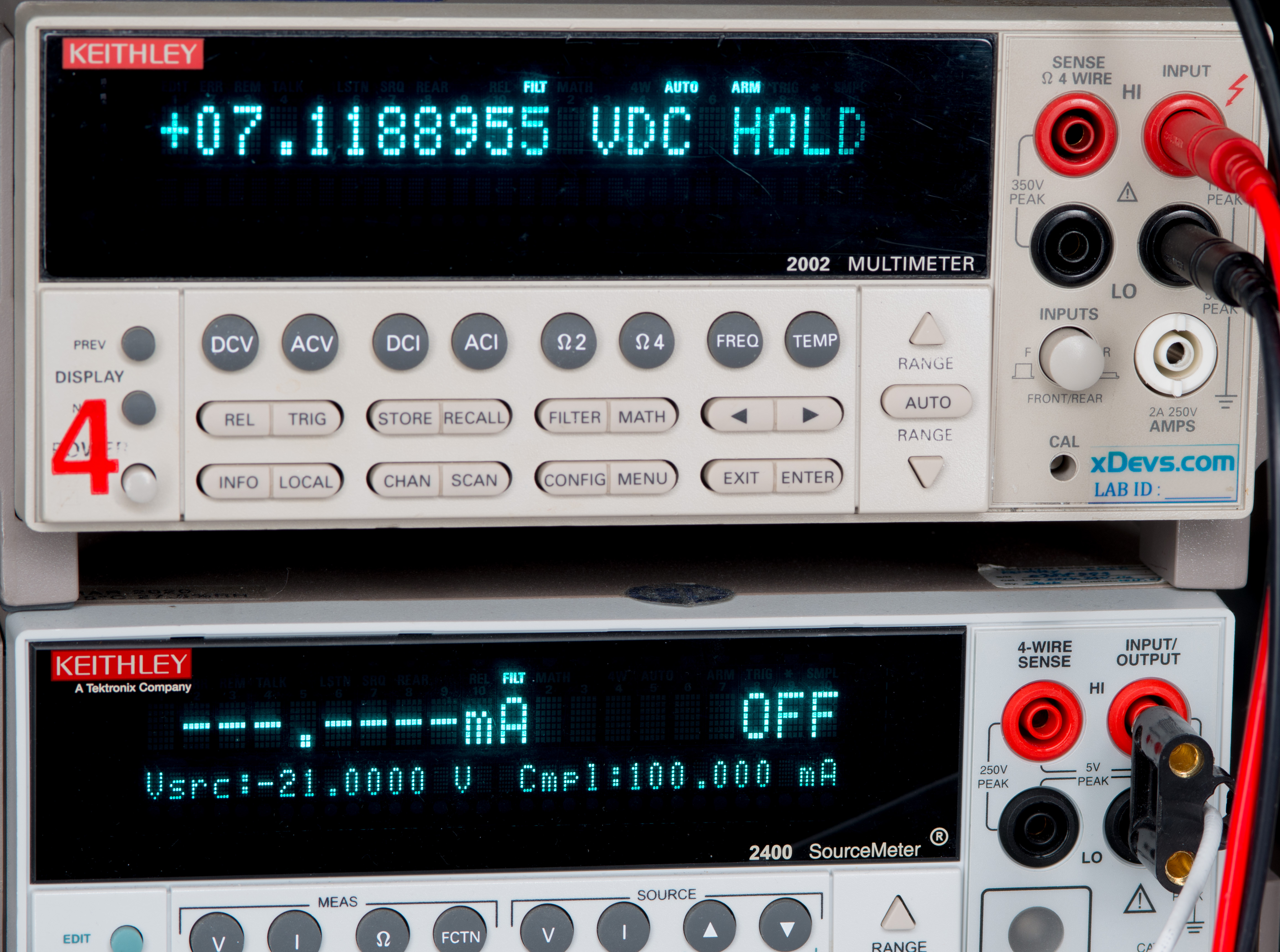
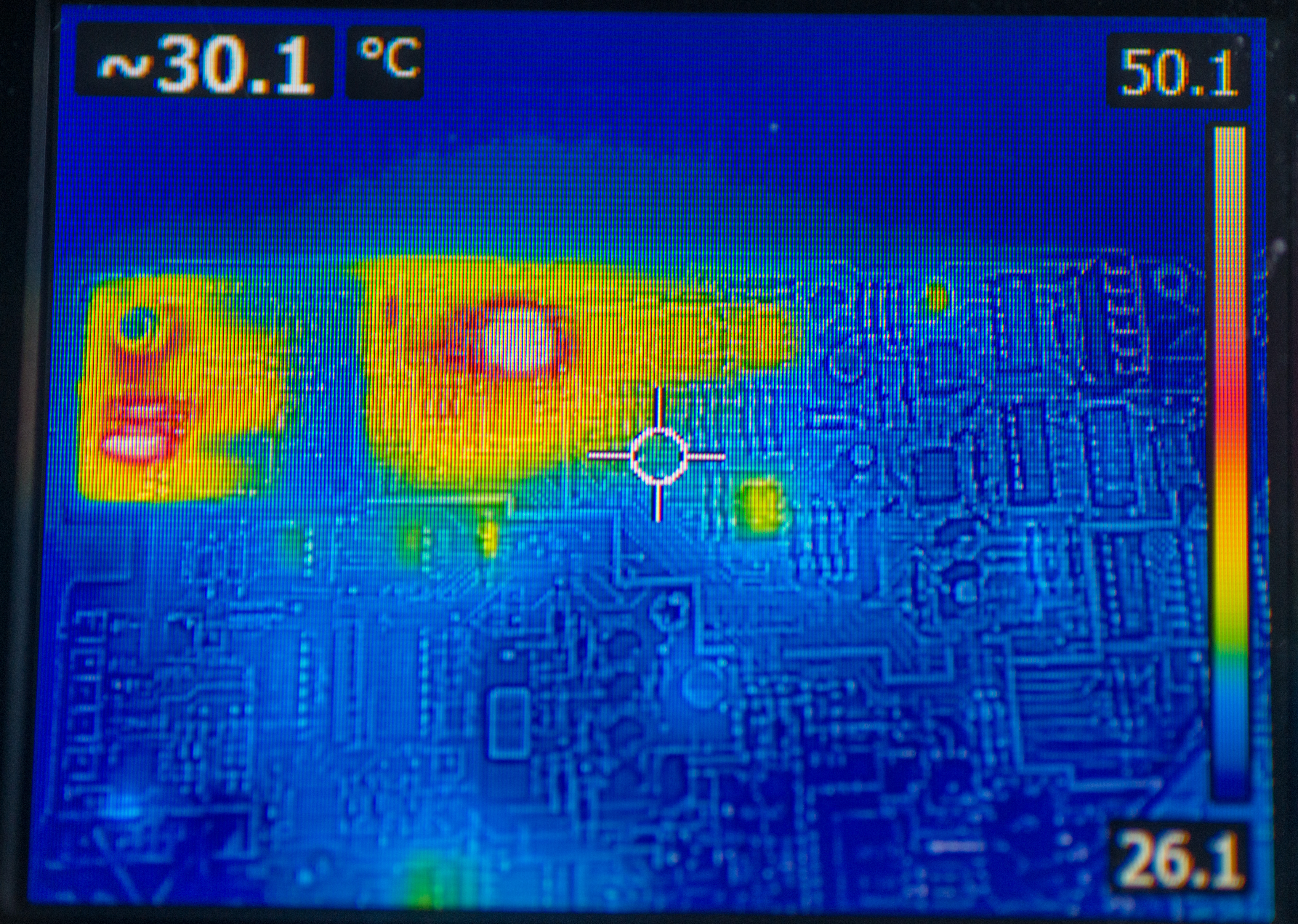
And indeed we have good +7.1-ish VDC output at A9 output. Quick cheap with Flir E4 also shows reasonable temperatures around few chips on A1 board.
Next step would be to obtain some missing parts stolen from this A1 PCBA and install it into P3459 mainframe so we can have more stuff interconnected for further troubleshooting.
Replacing missing parts on A1
Below is list of all components missing or removed from this assembly.
| Component | HP part number | Part description | Part number [new part] | Cost for replacement | Purpose |
|---|---|---|---|---|---|
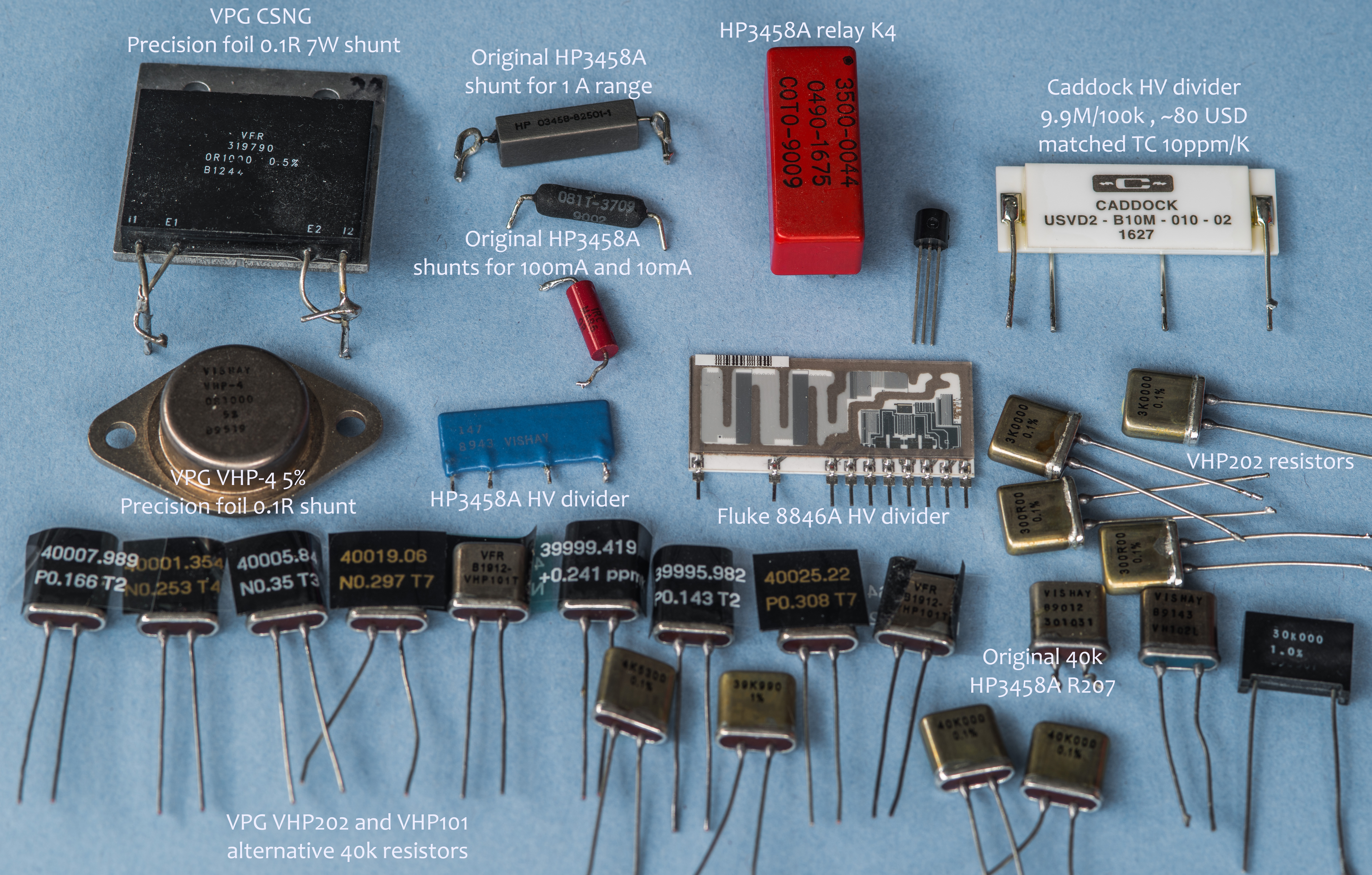
| R207 | 0699-1125 | Resistor 40 kΩ 0.1% 0.6W TC 0+-1.3 ppm/K | VHP101 | $50 | Reference resistor, 1µA range shunt |
| R211 | 0699-1627 | Resistor 9 Ω 0.1% 0.125W TC ±10 ppm/K | ? | ? | 10 mA range shunt |
| R212 | 0811-3709 | Resistor 1 Ω 1% 3W precision wirewound TC ±50 ppm/K | ? | ? | 100 mA range shunt |
| R213 | 03458-82501 | Resistor 0.1 Ω 10% TC ±5 ppm/K, 4-wire | ? | ? | 1 A range shunt |
| RP7 | 1810-1170 | Network resistor, 9.9 MΩ | 100 kΩ, 9 SIP | ? | High-voltage divider |
| K4 | 0490-1675 | Relay, 5µV Low TEMF, Reed | COTO 3500-0044 | ? | Low thermal relay for divider HV input |
| R307 | 0699-2427 | Resistor 300 Ω 0.5% 0.3W TC ±1.3 ppm/K | ? | ? | Range resistor for OHMF current source 10mA range |
| R310 | 0699-2425 | Resistor 10000 Ω 0.5% 0.3W TC ±1.3 ppm/K | ? | ? | Range resistor for OHMF current source compliance |
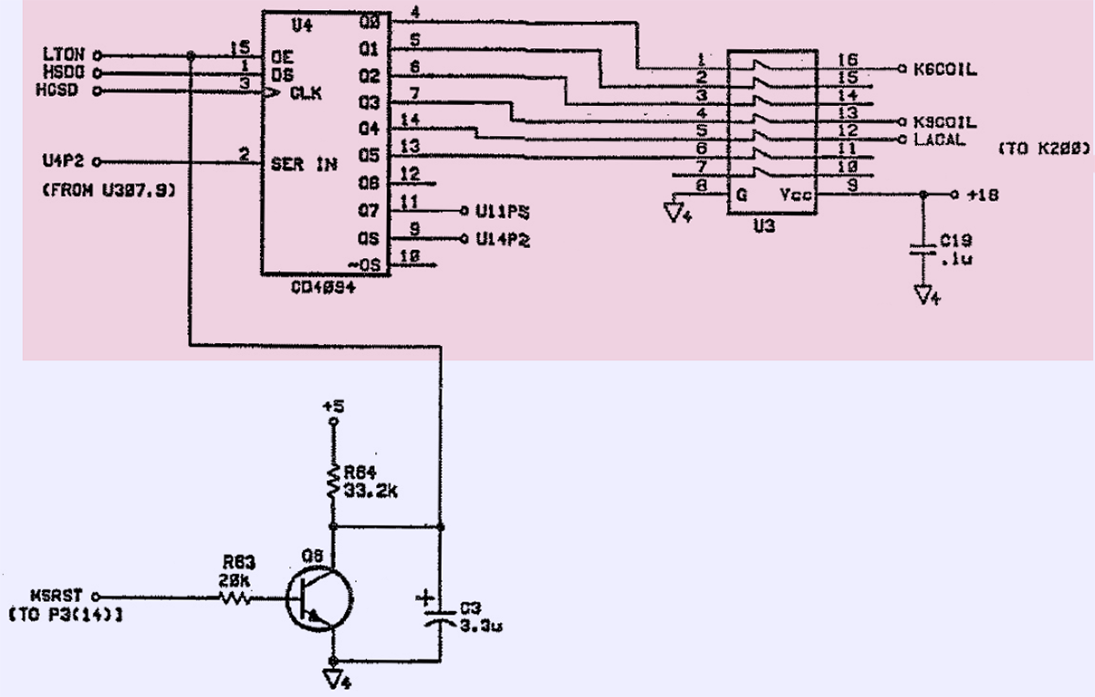
| Q6 | 1854-1024 | NPN Silicon transistor, Pd 350 mW, FT 300 MHz | 2N3904 | ? | Register control switch for U4 |
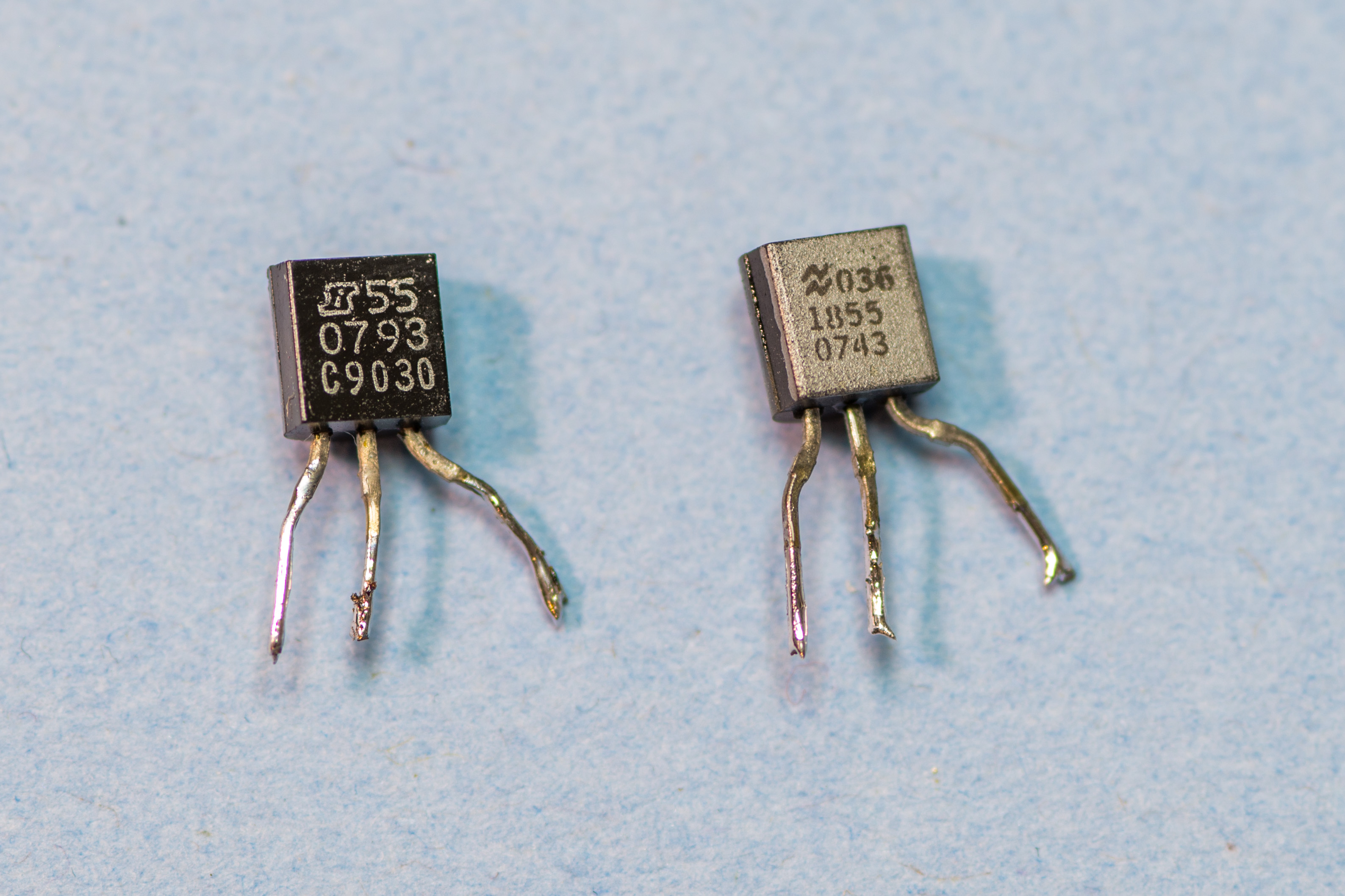
| Q15 | 1855-0743 | Transistor JFET N-channel depletion TO-92 Si | NSID5092/F50188A | ? | Switch for auxilary signals to DC analog bus |
| Q16 | 1855-0793 | Transistor JFET N-channel depletion TO-92 Si | Siliconix J2472 [LIS PF5301] | ? | Switch for auxilary signals to DC analog bus |
| CR11 | 1901-0527 | Diode-current regulator 75V DO-7 | ? | ? | Current bias for bootstrap precharge control |
| R39 | 0757-0280 | Resistor 1000 Ω 1% 0.125W ±100 ppm/K | CT4-1/8-TO-1001-F | ? | Bias for Q7 JFET input amplifier at U12 |
| R40 | 0757-0280 | Resistor 1000 Ω 1% 0.125W ±100 ppm/K | CT4-1/8-TO-1001-F | ? | Bias for Q7 JFET input amplifier at U12 |
| R41 | 0698-3279 | Resistor 4990 Ω 1% 0.125W ±100 ppm/K | CT4-1/8-TO-4991-F | ? | Bias for Q7 JFET input amplifier at U12 |
| R42 | 0698-3279 | Resistor 4990 Ω 1% 0.125W ±100 ppm/K | CT4-1/8-TO-4991-F | ? | Bias for Q7 JFET input amplifier at U12 |
| C8 | 0160-4807 | Capacitor 33pF 5% 100V Ceramic, ±30 ppm/K | SA102A330JAAH | ? | Bootstrap precharge RC network |
| C9 | 0160-4807 | Capacitor 33pF 5% 100V Ceramic, ±30 ppm/K | SA102A330JAAH | ? | Bootstrap precharge RC network |
| C12 | 0160-4571 | Capacitor 100nF +80/-20% 50V Ceramic | SA105E104ZAAH | ? | +18 power decoupling |
| C13 | 0160-4571 | Capacitor 100nF +80/-20% 50V Ceramic | SA105E104ZAAH | ? | -18 power decoupling |
| C24 | 0160-4801 | Capacitor 100pF 5% 100V Ceramic | SA102E101JAAH | ? | AC compensation for U12 network |
| C304 | 0160-4571 | Capacitor 100nF +80/-20% 50V Ceramic | SA105E104ZAAH | ? | +18 power decoupling |
| C305 | 0160-4571 | Capacitor 100nF +80/-20% 50V Ceramic | SA105E104ZAAH | ? | +18 power decoupling |
| U4 | 1820-1662 | Shift-register IC, CMOS, serial in, parallel-out, 8 bit | MC14094BCP | ? | Control decoder |
| U12 | 1826-1544 | IC Opamp High slew rate, 8DIP | MC34081P | ? | Bootstrap amplifier for internal guard circuitry |
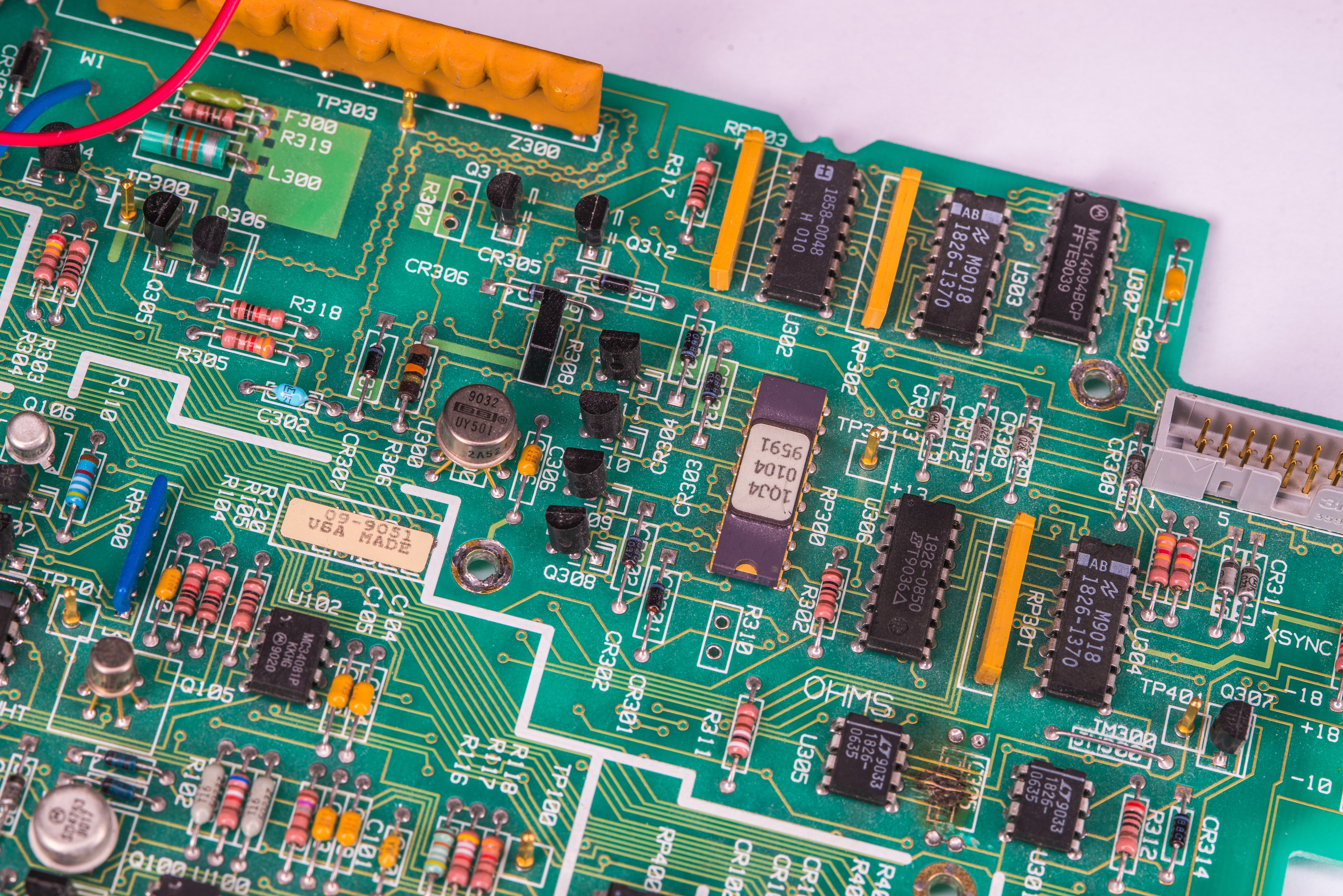
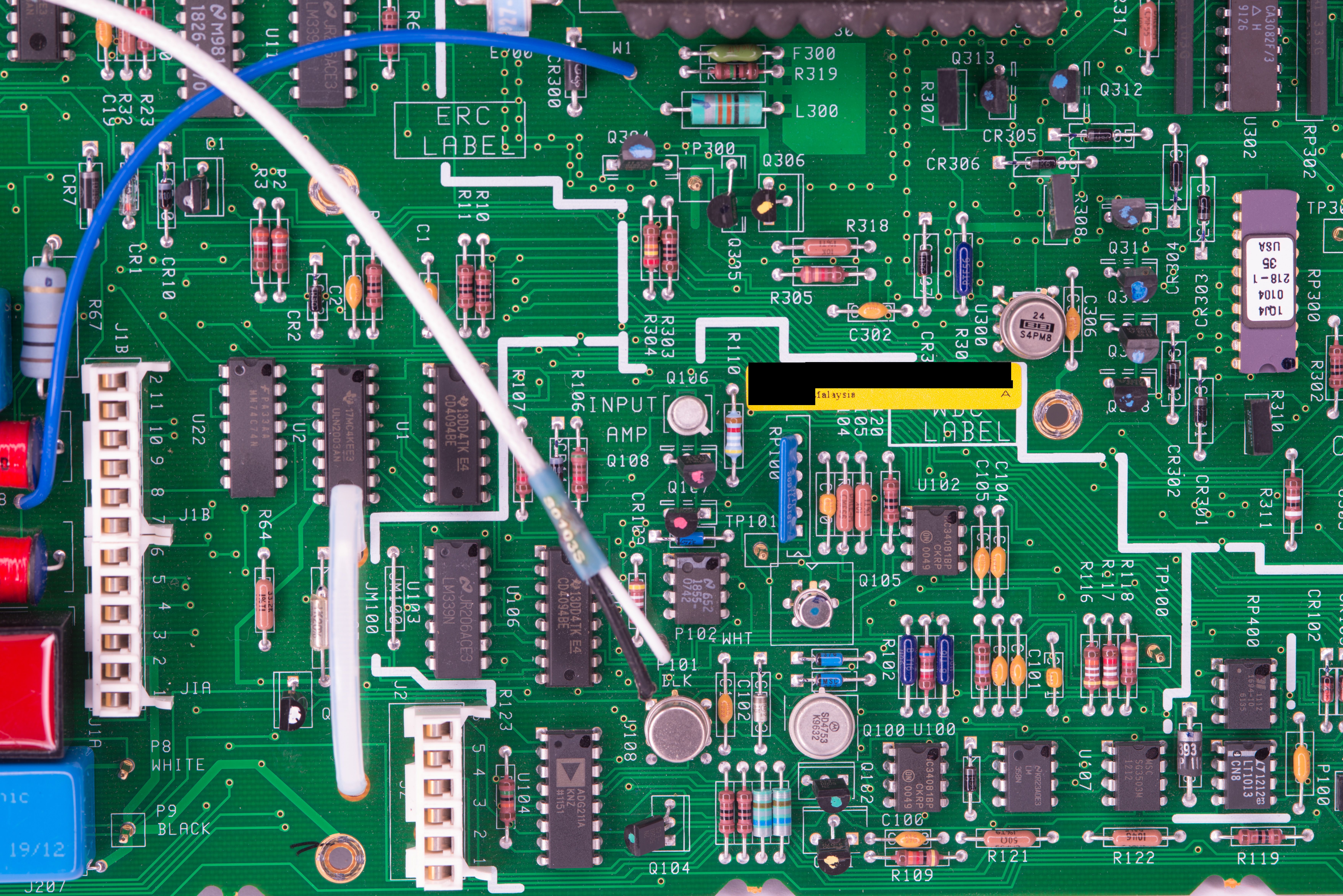
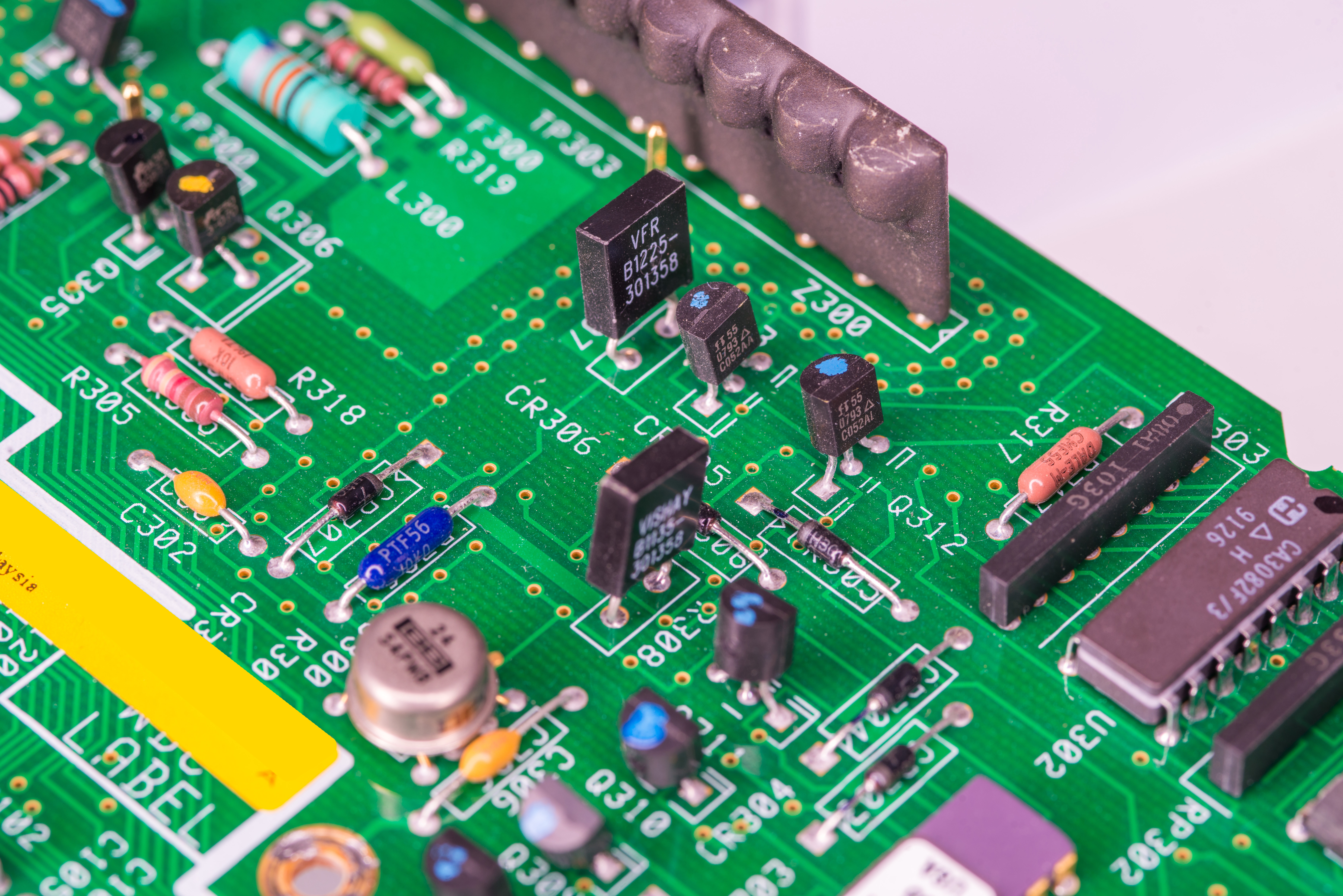
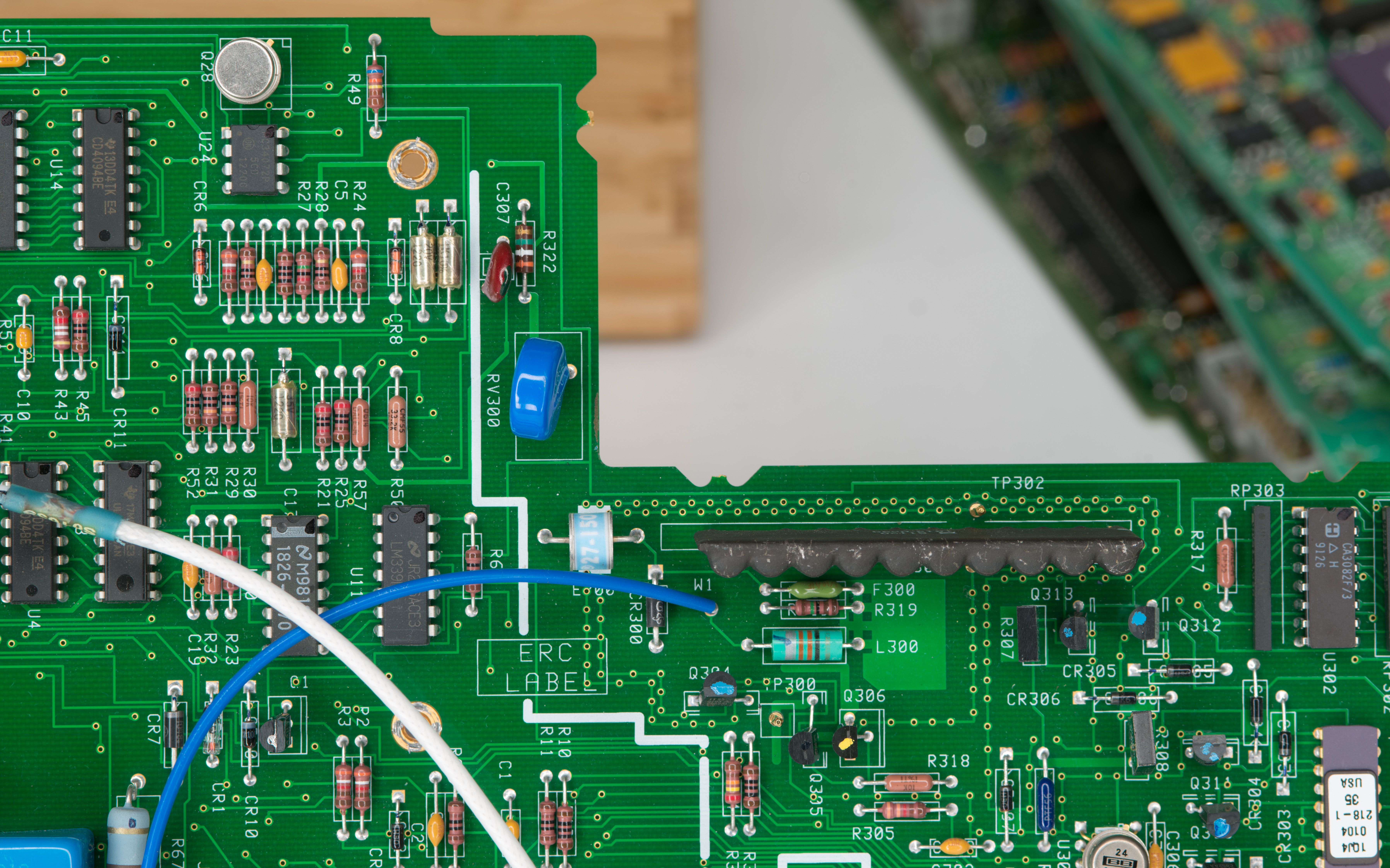
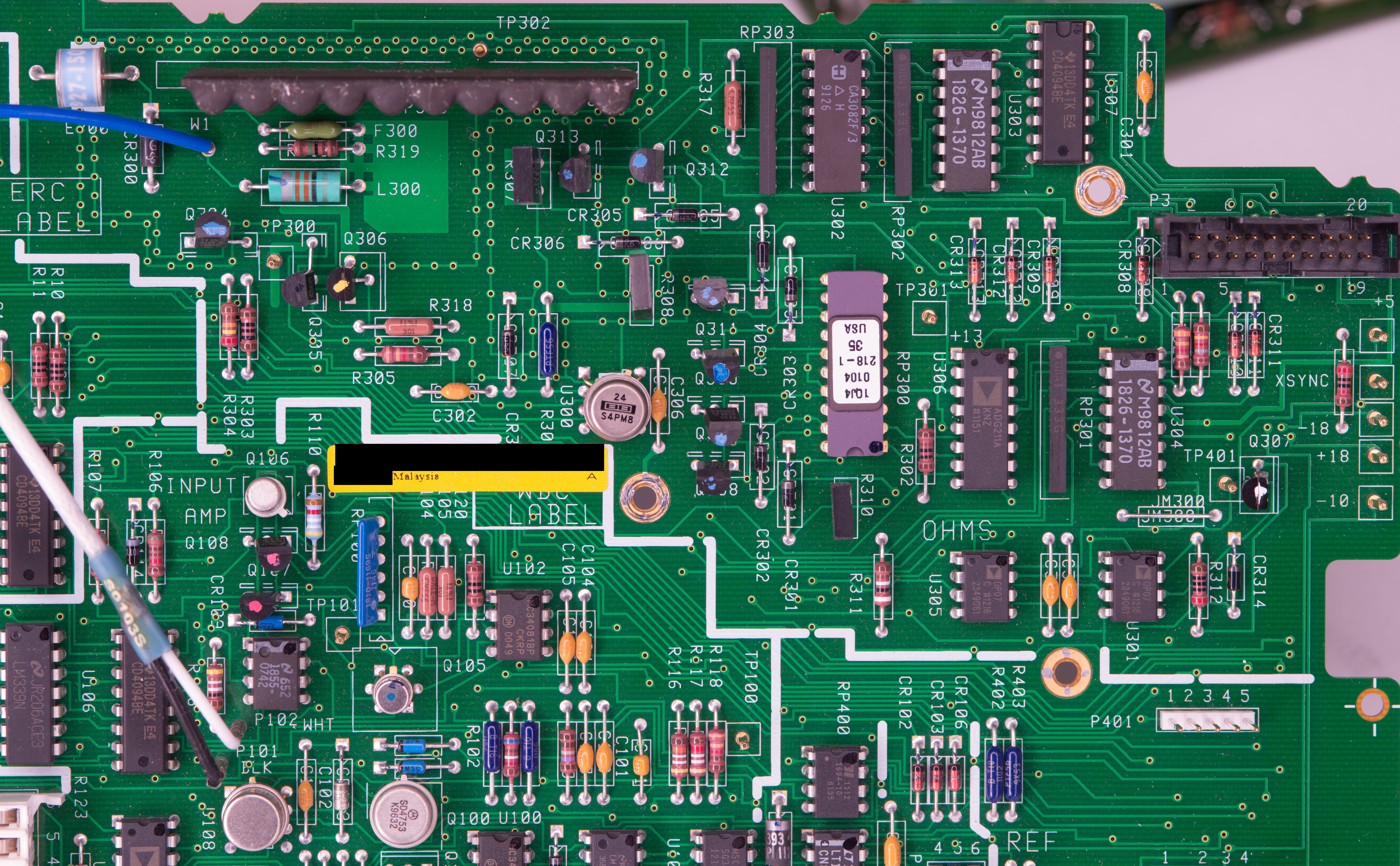
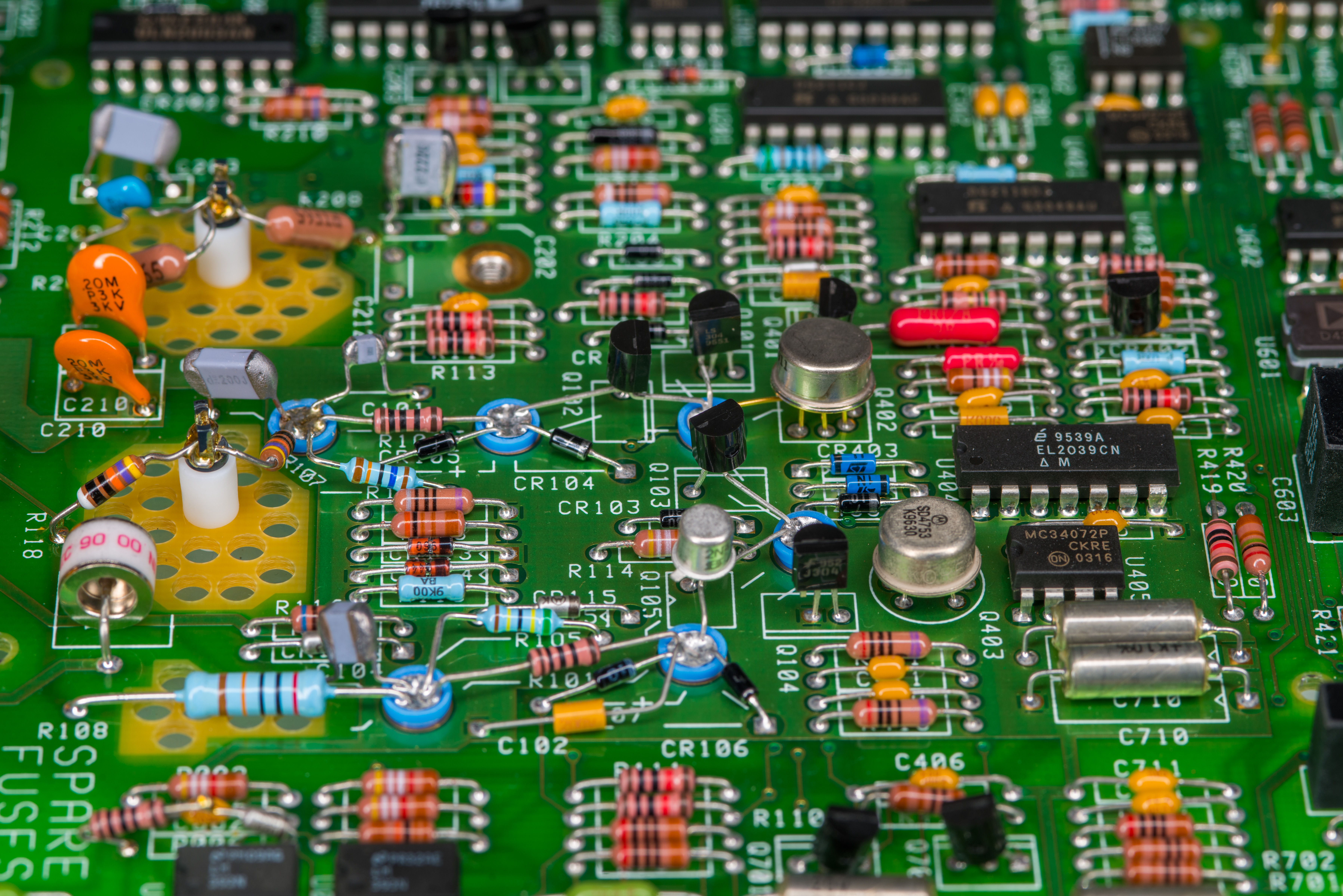
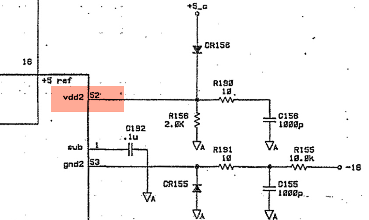
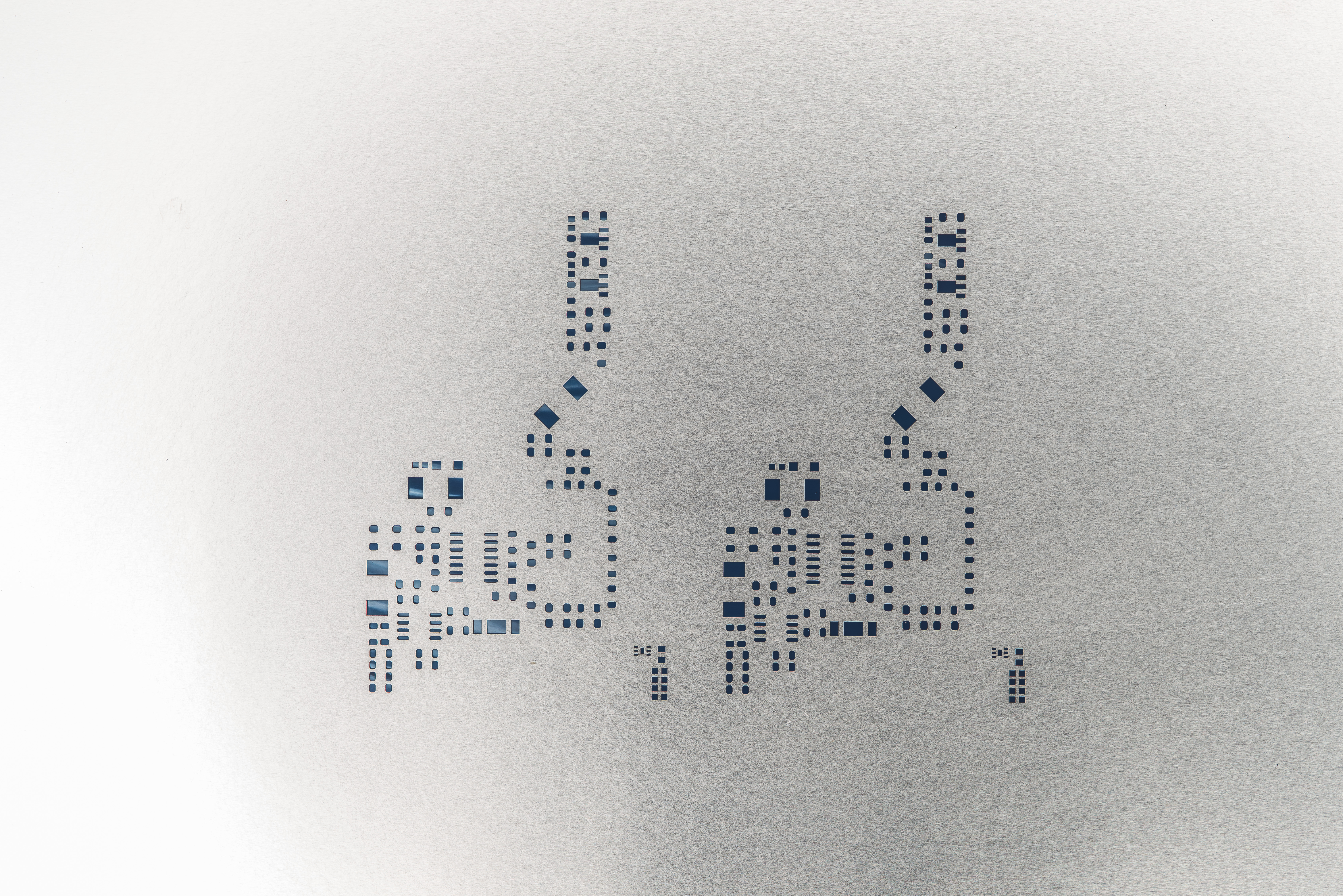
Here is visual layout overview of missing hardware:
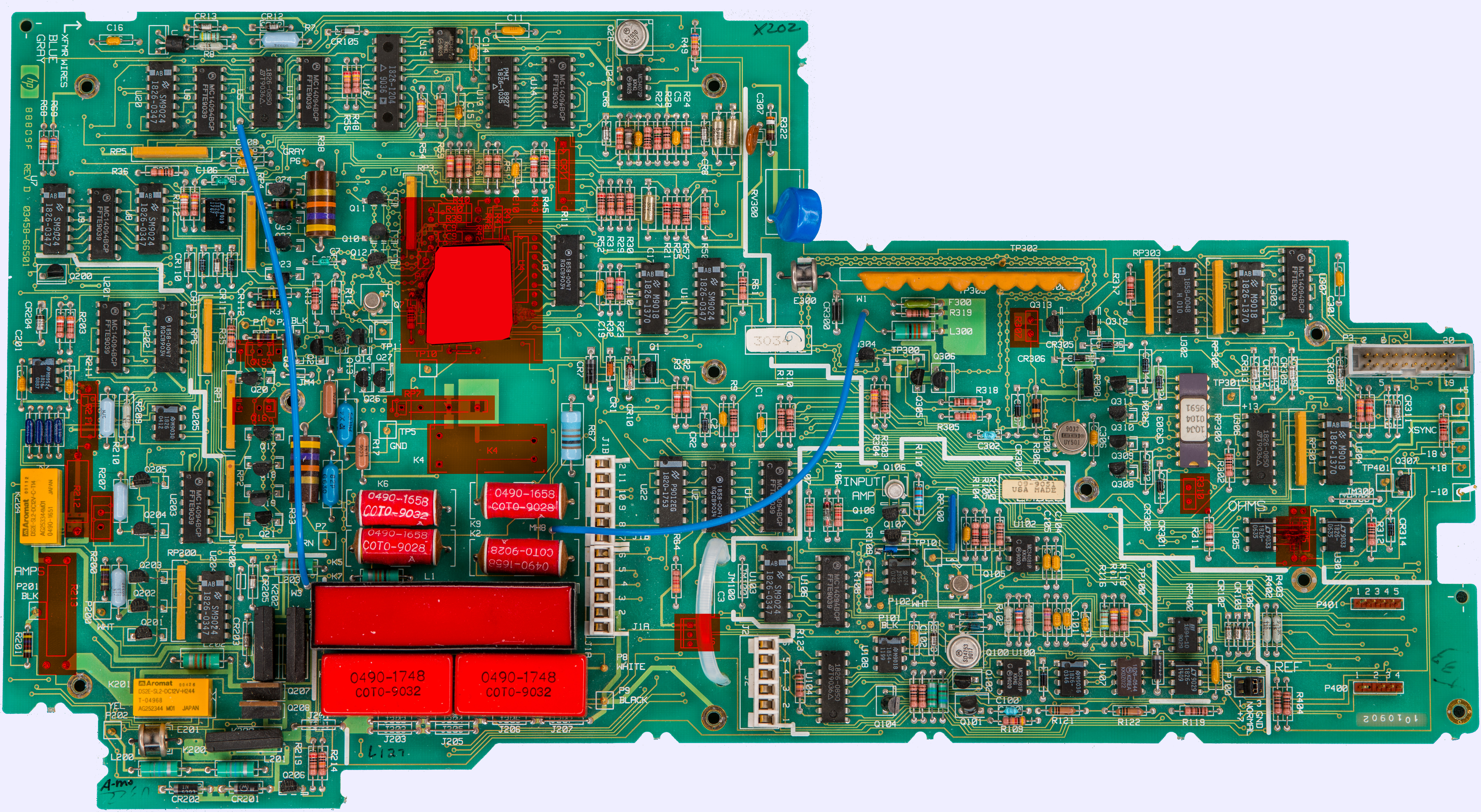
Some of the parts I still have so it is trivial to reinstall them back to the board.
Number of critical components we can replace in future with different more expensive parts, to investigate effect of the change on performance of the instrument. However, at this moment we just want to restore original functionality of the instrument, for which original HP components will be installed where possible.
Shunts are reinstalled, short of 9 Ω which I’ll put back later after some checks. Low thermal COTO 3500 relay and blue Vishay high voltage divider with 9.9 MΩ and 100 kΩ is also reinstalled back.

Current source is missing some of epoxy metal foil resistors, but I might just put fancy VHP ones instead there.
I don’t have CR11 anymore, so to find a suitable modern replacement need to test same current regulator installed on CR10 position. For this trusty Keithley 2400 is used, sourcing voltage with current compliance set to 10mA-ish.
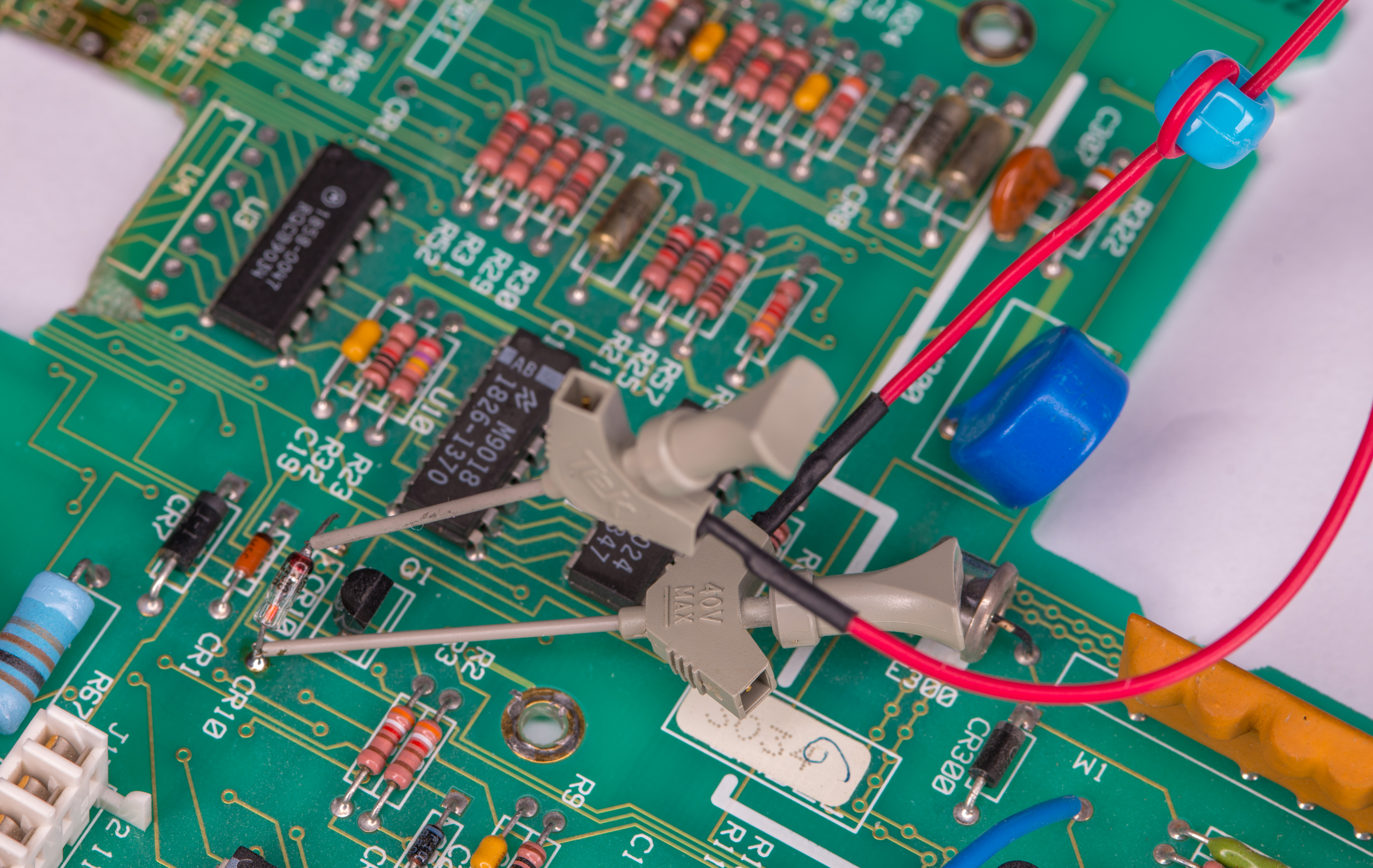
One leg of CR10 was lifted off the PCB so we can get isolated measurement without risking anything else on PCB.
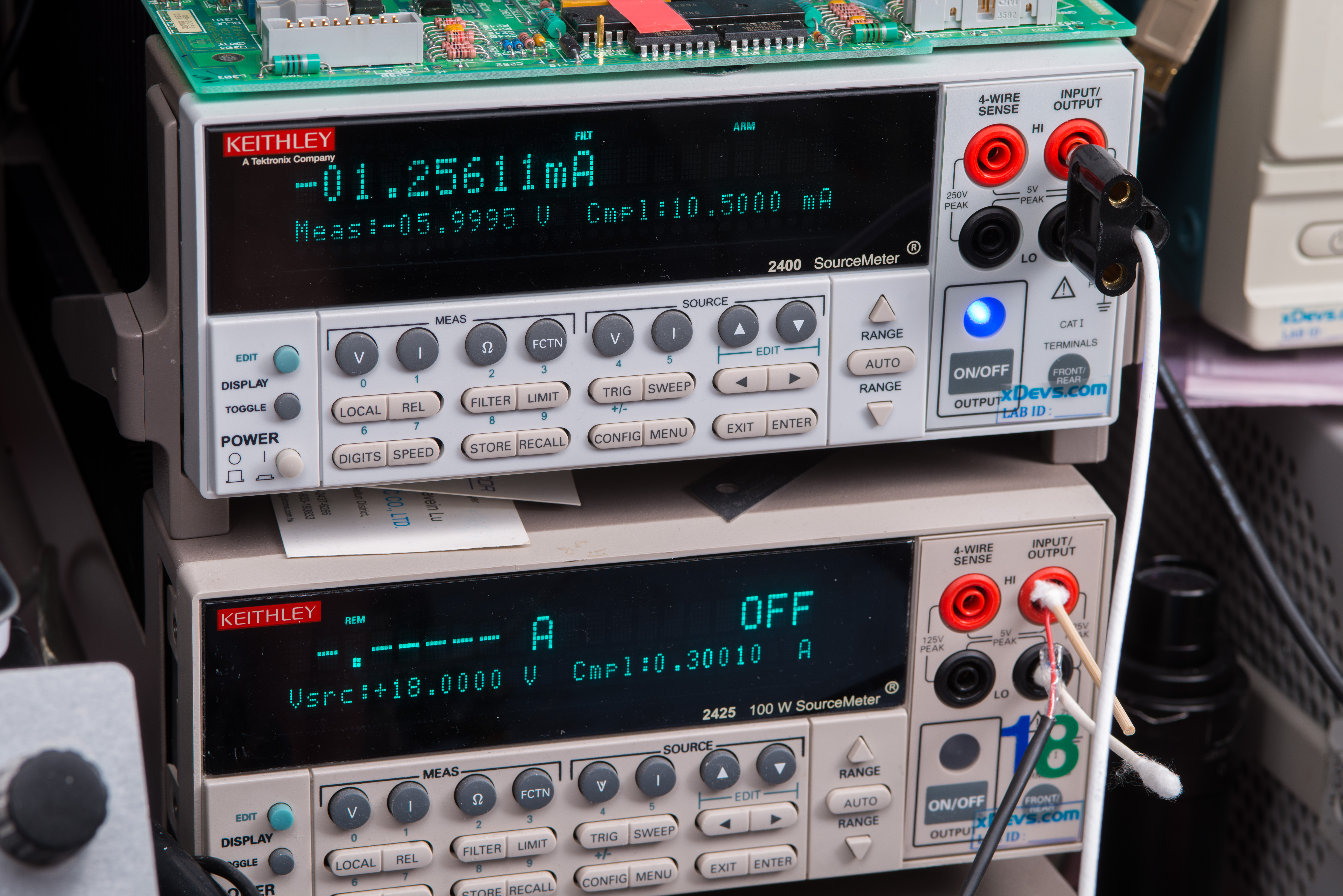
Measurement revealed that CR10 forward current is 1.25mA. Suitable replacement would be something like 1N5299 or LIS J506.
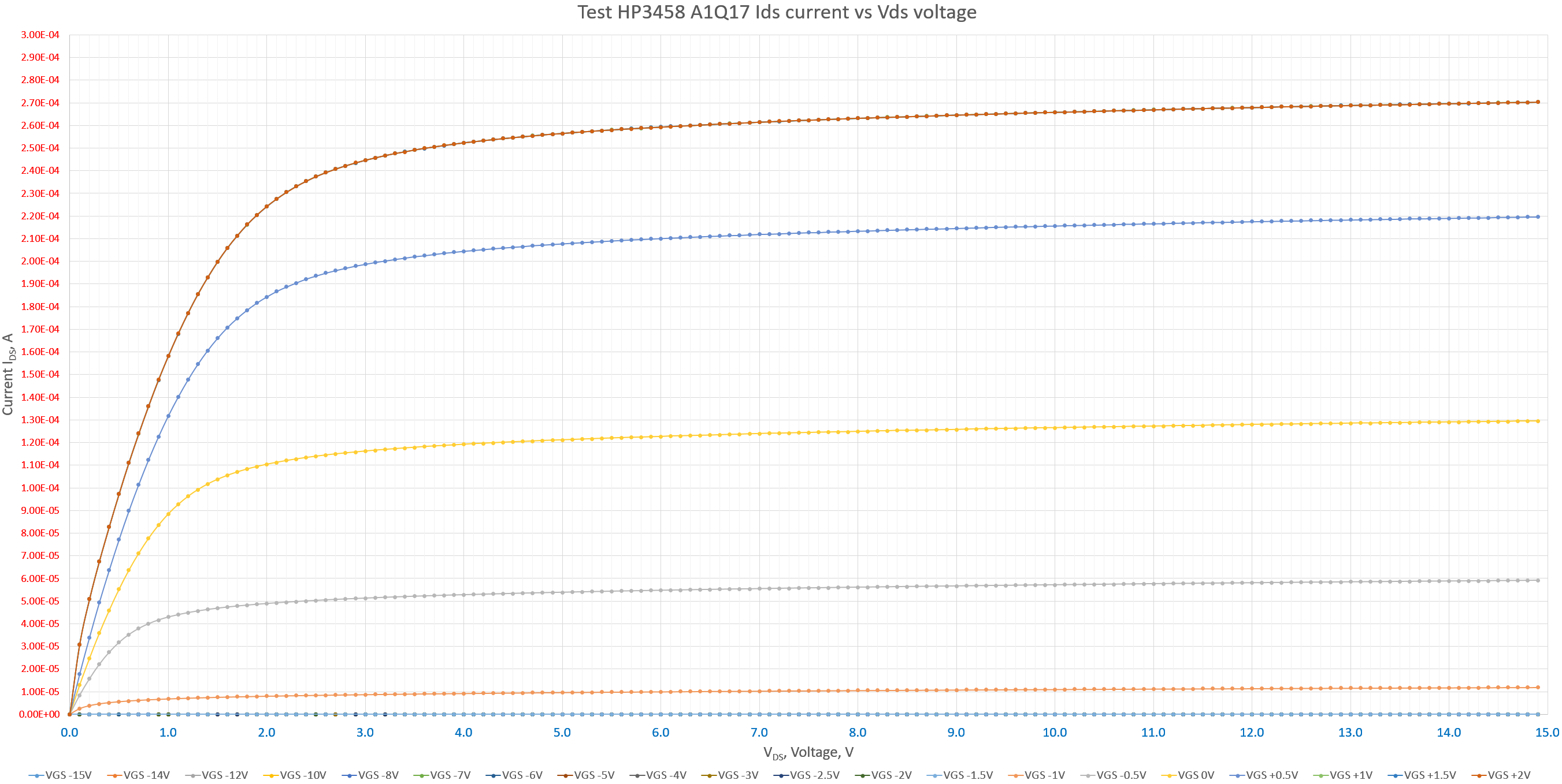
Missing Q15 is custom-made NSID5092/F50188A which is N-channel JFETs, specific to HP 3458A. Modern RoHS-version Keysight 3458AR also using custom part in this position from Linear Systems, P/N LS304. There are no datasheets available online to either old or new part. Best option would be to salvage such transistor from another 3458A, but in absence of such our second best path is to de-solder same component from A1 and test it on parametric analyzer to find out required parameters.
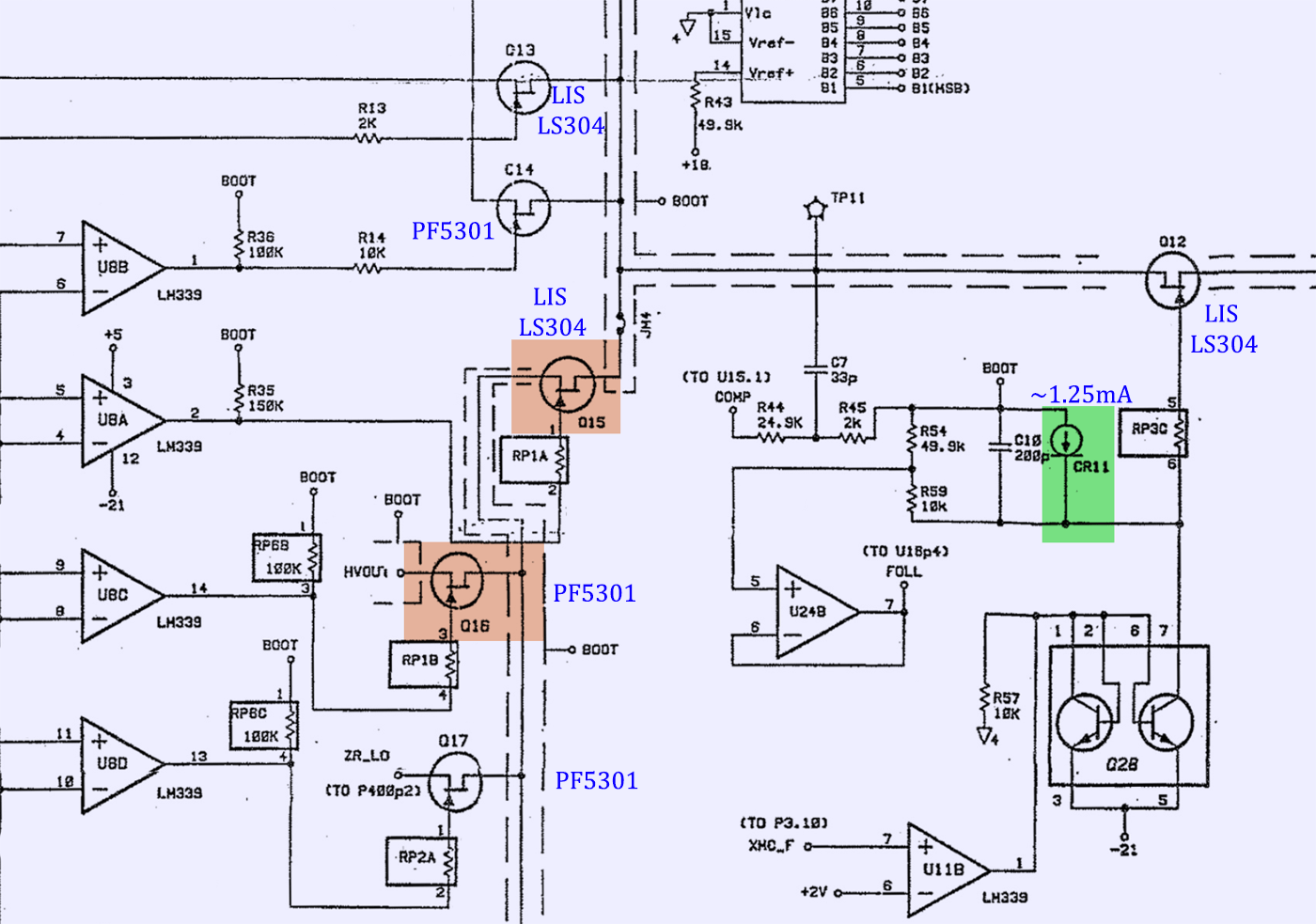
I have better luck with missing Q16 for which original HP board used Siliconix J2472.
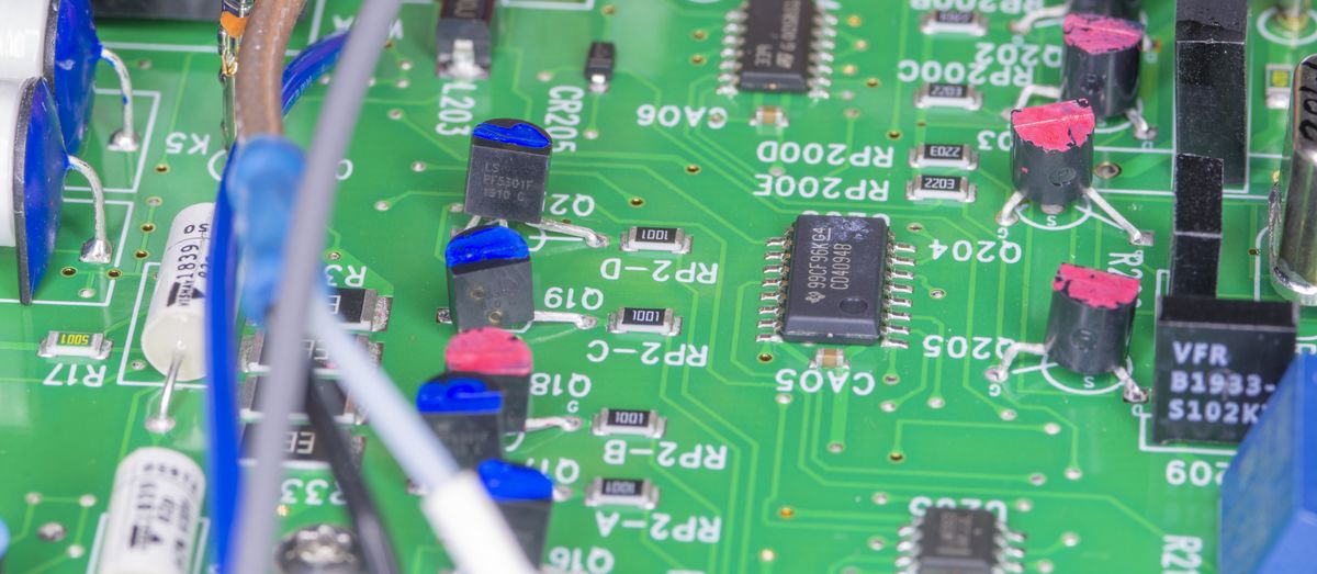
Image : Linear Systems PF5301 on newer RoHS 3458AR A1 DC board
It is unobtainable today as well, but 3458AR replaced it with still active production LIS PF5301 high-impedance JFET.
With help of international community and friends this project was rescued once again. I’ve managed to secure some broken boards, including three A1 DC boards and even A2 AC board. Now this build jumped on the fast track lane, since it is saving a lot of development and patch-work on blown up A1 DC board you seen above.
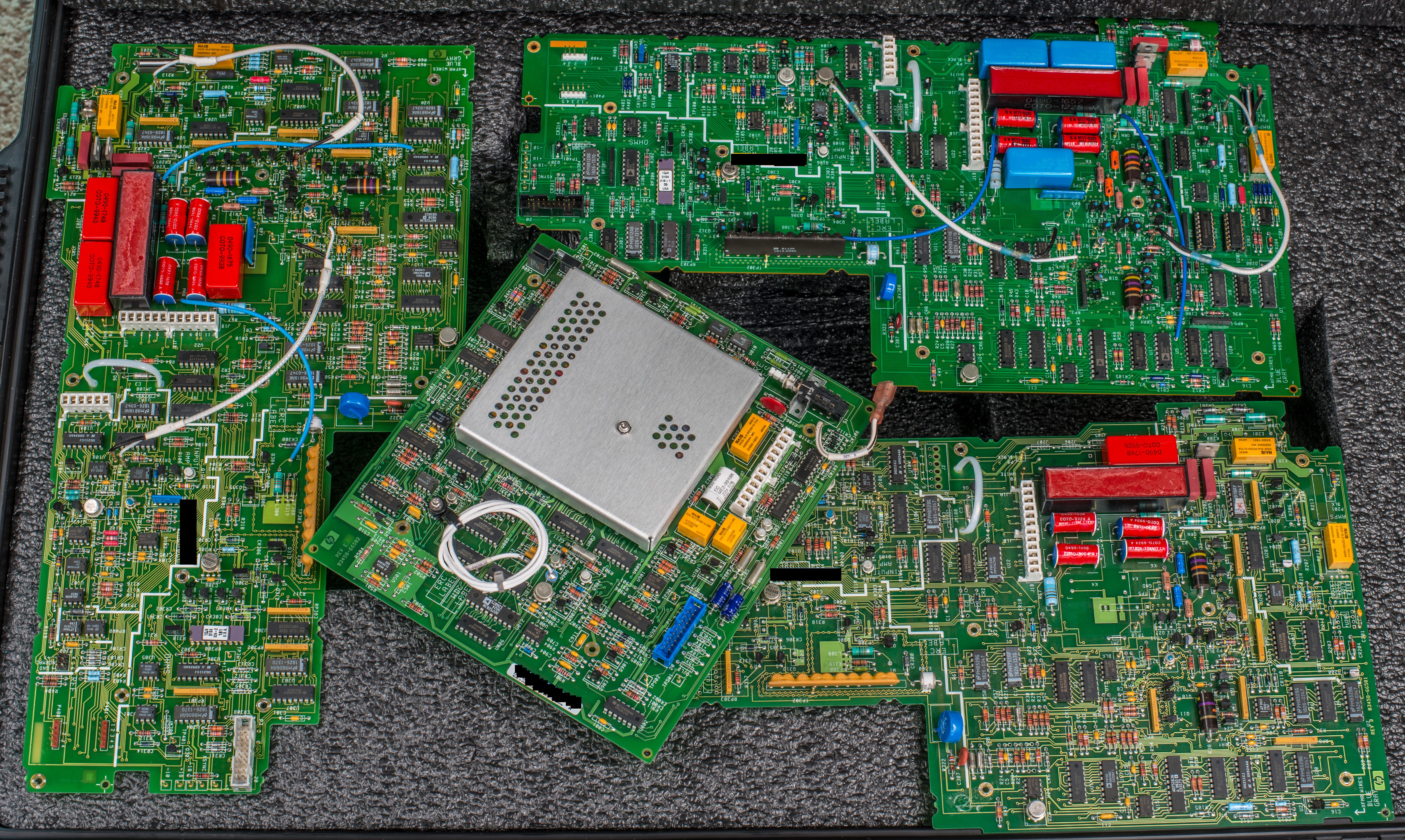
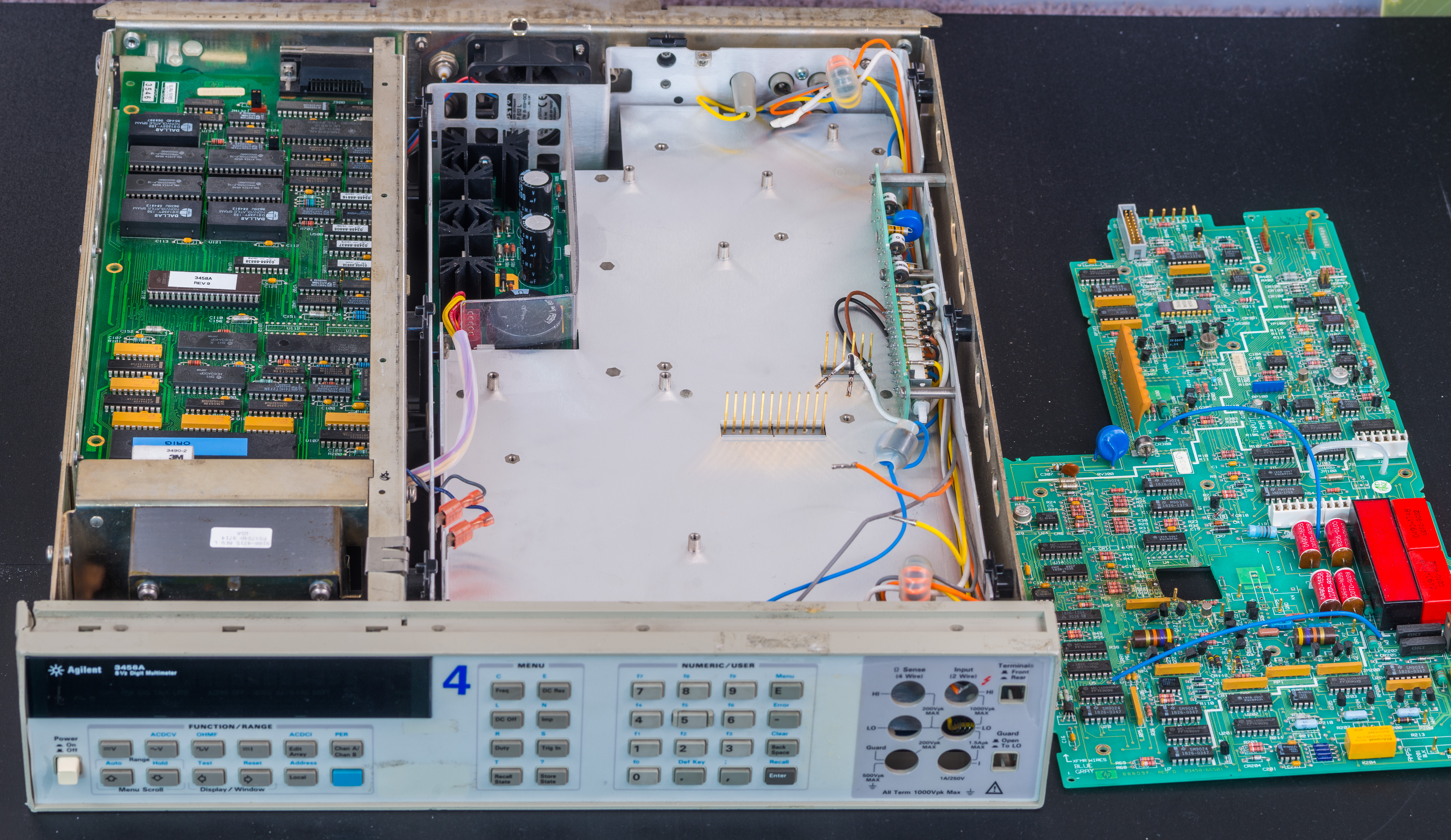
Full high-resolution photos of the acquired hardware presented below. All photos are clickable as usual. Agilent A1 DC board from year 2012.
Older A1 DC board 1. Pretty much complete, from HP era with date codes around year 36 week 1999.
Older A1 DC board 2. This board was used as parts mule and have lot of missing parts.
Below is list of all components missing or removed from this assembly.
| Component | HP part number | Part description | Part number [new part] | Cost for replacement | Purpose |
|---|---|---|---|---|---|
| R207 | 0699-1125 | Resistor 40 kΩ 0.1% 0.6W TC 0+-1.3 ppm/K | VHP101 | $50 | Reference resistor, 1µA range shunt |
| R211 | 0699-1627 | Resistor 9 Ω 0.1% 0.125W TC ±10 ppm/K | ? | ? | 10 mA range shunt |
| R212 | 0811-3709 | Resistor 1 Ω 1% 3W precision wirewound TC ±50 ppm/K | ? | ? | 100 mA range shunt |
| R213 | 03458-82501 | Resistor 0.1 Ω 10% TC ±5 ppm/K, 4-wire | ? | ? | 1 A range shunt |
| RP7 | 1810-1170 | Network resistor, 9.9 MΩ | 100 kΩ, 9 SIP | ? | High-voltage divider |
| K4 | 0490-1675 | Relay, 5µV Low TEMF, Reed | COTO 3500-0044 | ? | Low thermal relay for divider HV input |
| K1 | x0490-1675 | Relay, 5µV Low TEMF, Reed | COTO 3500-0044 | ? | Low thermal relay for divider HV input |
| K200 | x0490-1675 | Relay, 5µV Low TEMF, Reed | COTO 3500-0044 | ? | Low thermal relay for divider HV input |
| E201 | x0490-1675 | Relay, 5µV Low TEMF, Reed | COTO 3500-0044 | ? | Low thermal relay for divider HV input |
| Q208 | x0490-1675 | Relay, 5µV Low TEMF, Reed | COTO 3500-0044 | ? | Low thermal relay for divider HV input |
| R215 | 0699-2427 | Resistor 300 Ω 0.5% 0.3W TC ±1.3 ppm/K | ? | ? | Range resistor for OHMF current source 10mA range |
| R216 | 0699-2427 | Resistor 300 Ω 0.5% 0.3W TC ±1.3 ppm/K | ? | ? | Range resistor for OHMF current source 10mA range |
| R217 | 0699-2427 | Resistor 300 Ω 0.5% 0.3W TC ±1.3 ppm/K | ? | ? | Range resistor for OHMF current source 10mA range |
| R218 | 0699-2427 | Resistor 300 Ω 0.5% 0.3W TC ±1.3 ppm/K | ? | ? | Range resistor for OHMF current source 10mA range |
| R307 | 0699-2427 | Resistor 300 Ω 0.5% 0.3W TC ±1.3 ppm/K | ? | ? | Range resistor for OHMF current source 10mA range |
| R310 | 0699-2425 | Resistor 10000 Ω 0.5% 0.3W TC ±1.3 ppm/K | ? | ? | Range resistor for OHMF current source compliance |
| R26 | x0757-0280 | Resistor 10 Ω 1% 0.125W ±100 ppm/K | CT4-1/8-TO-1001-F | ? | Bias for Q7 JFET input amplifier at U12 |
| R28 | x0757-0280 | Resistor 10 Ω 1% 0.125W ±100 ppm/K | CT4-1/8-TO-1001-F | ? | Bias for Q7 JFET input amplifier at U12 |
| R306 | x0757-0280 | Resistor 10 Ω 1% 0.125W ±100 ppm/K | CT4-1/8-TO-1001-F | ? | Bias for Q7 JFET input amplifier at U12 |
| R312 | x0757-0280 | Resistor 10 Ω 1% 0.125W ±100 ppm/K | CT4-1/8-TO-1001-F | ? | Bias for Q7 JFET input amplifier at U12 |
| C24 | 0160-4801 | Capacitor 100pF 5% 100V Ceramic | SA102E101JAAH | ? | AC compensation for U12 network |
| C2 | 0160-4571 | Capacitor 100nF +80/-20% 50V Ceramic | SA105E104ZAAH | ? | +18 power decoupling |
| U302 | x1820-1662 | Shift-register IC, CMOS, serial in, parallel-out, 8 bit | MC14094BCP | ? | Control decoder |
| U205 | x1826-1544 | IC Opamp High slew rate, 8DIP | MC34081P | ? | Bootstrap amplifier for internal guard circuitry |
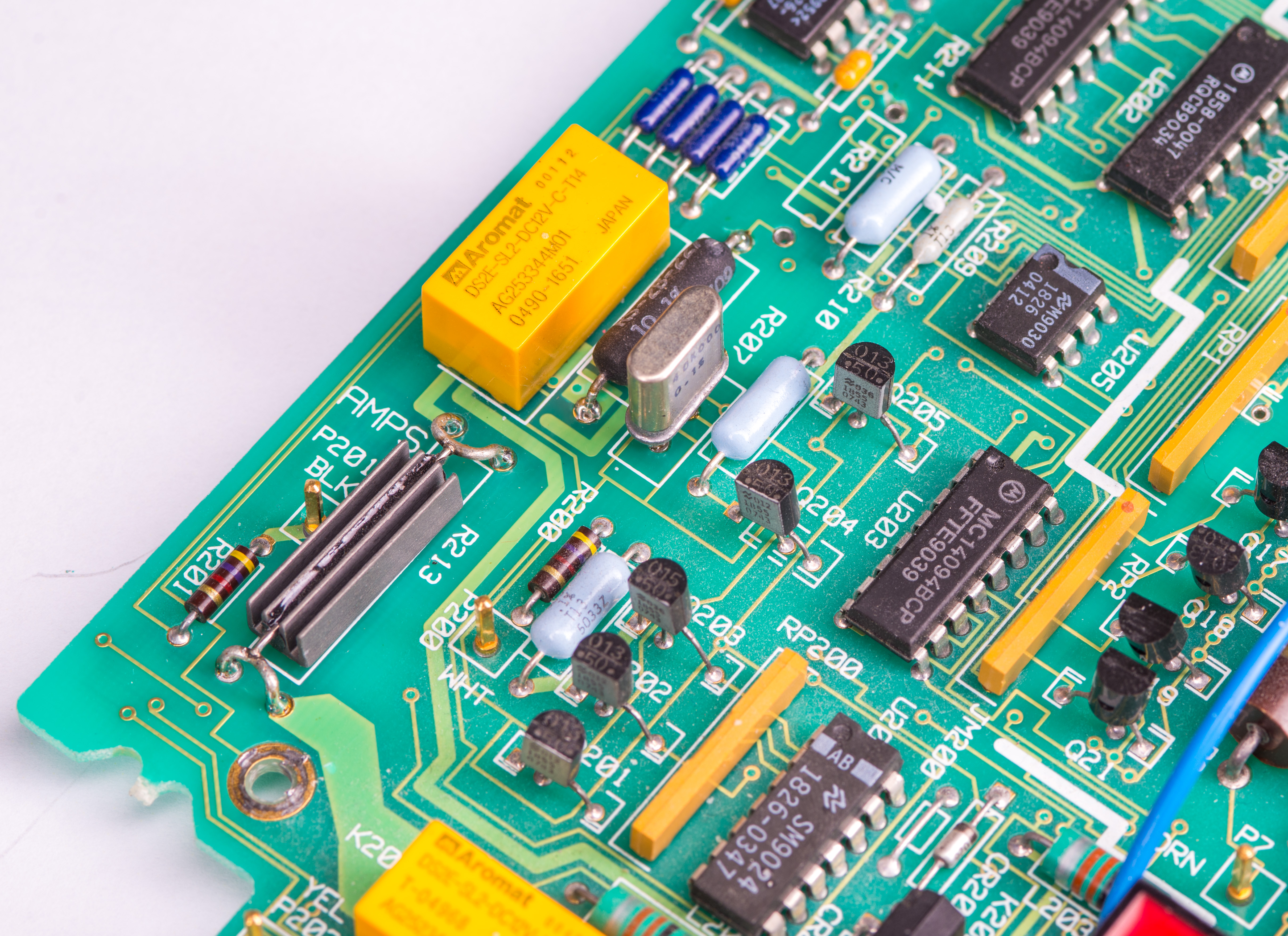
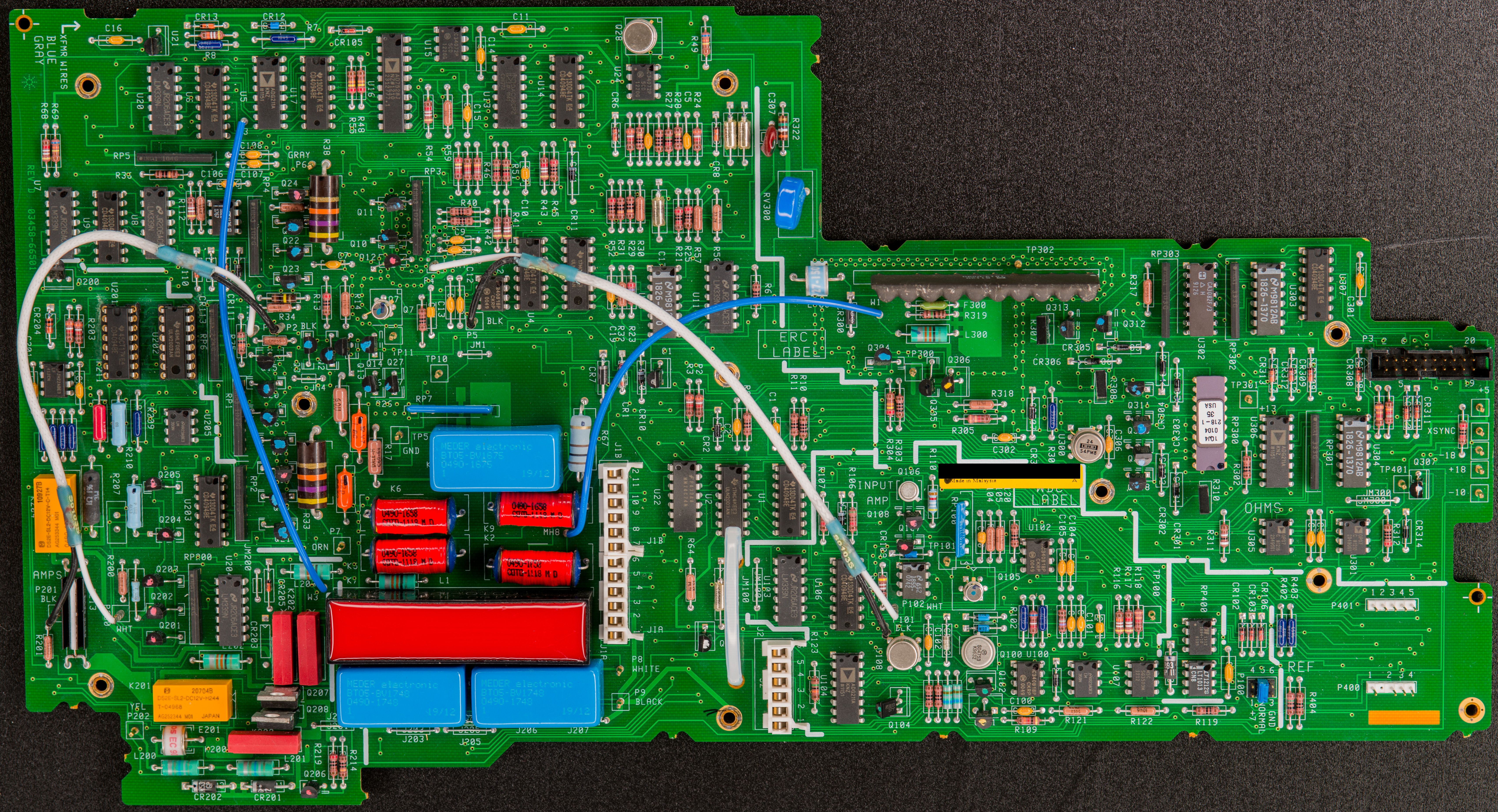
To repair the unit I’ll start with newer PCBA. VHP101 40 kΩ reference resistance is missing on the circuit board.
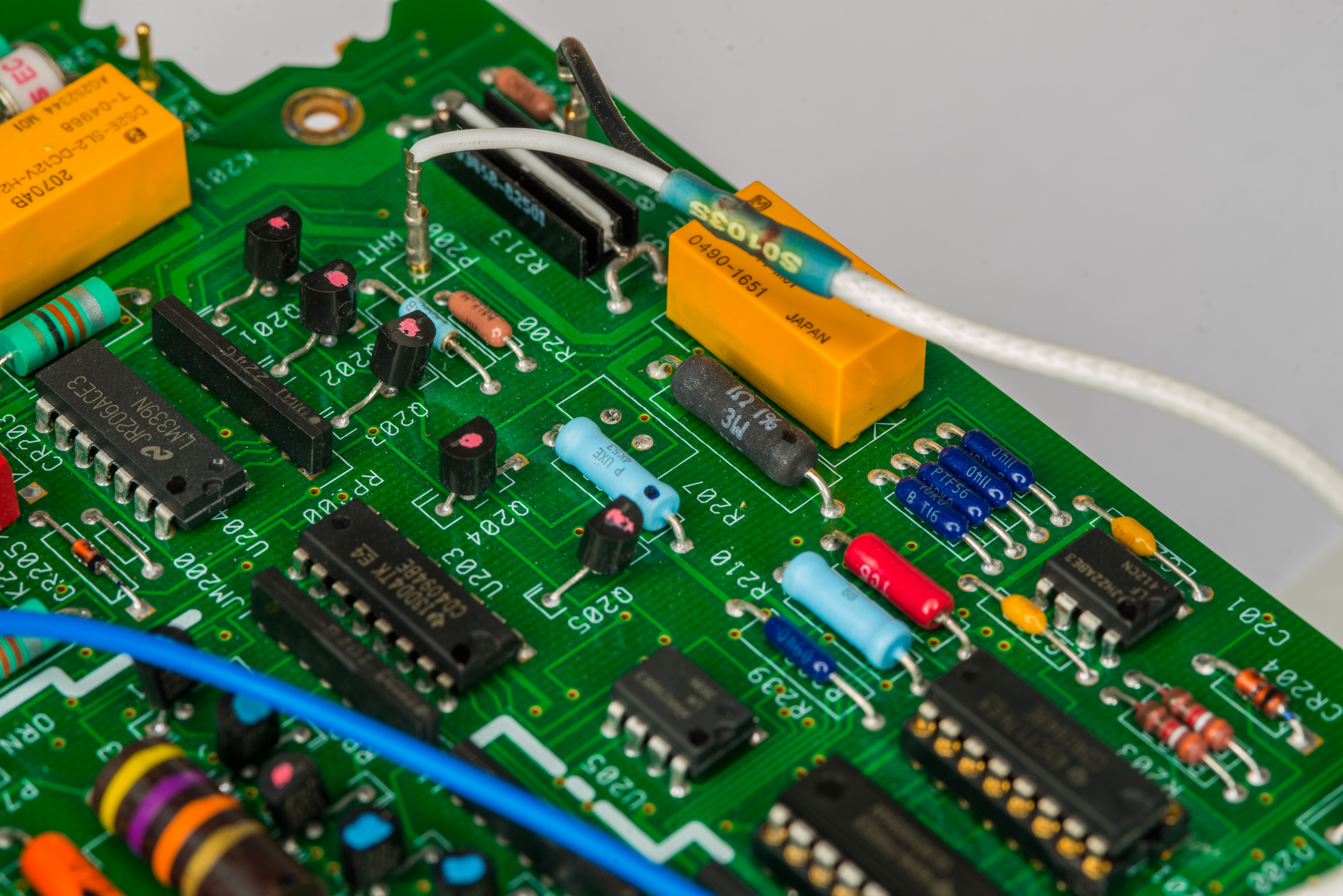
First I’d put brand new VHP101T 40 kΩ resistance standard on missing position R207. Previous owner has these salvaged for some other purpose, but other than long lead time it is not difficult to source new VHP101T resistor for A1 repair.
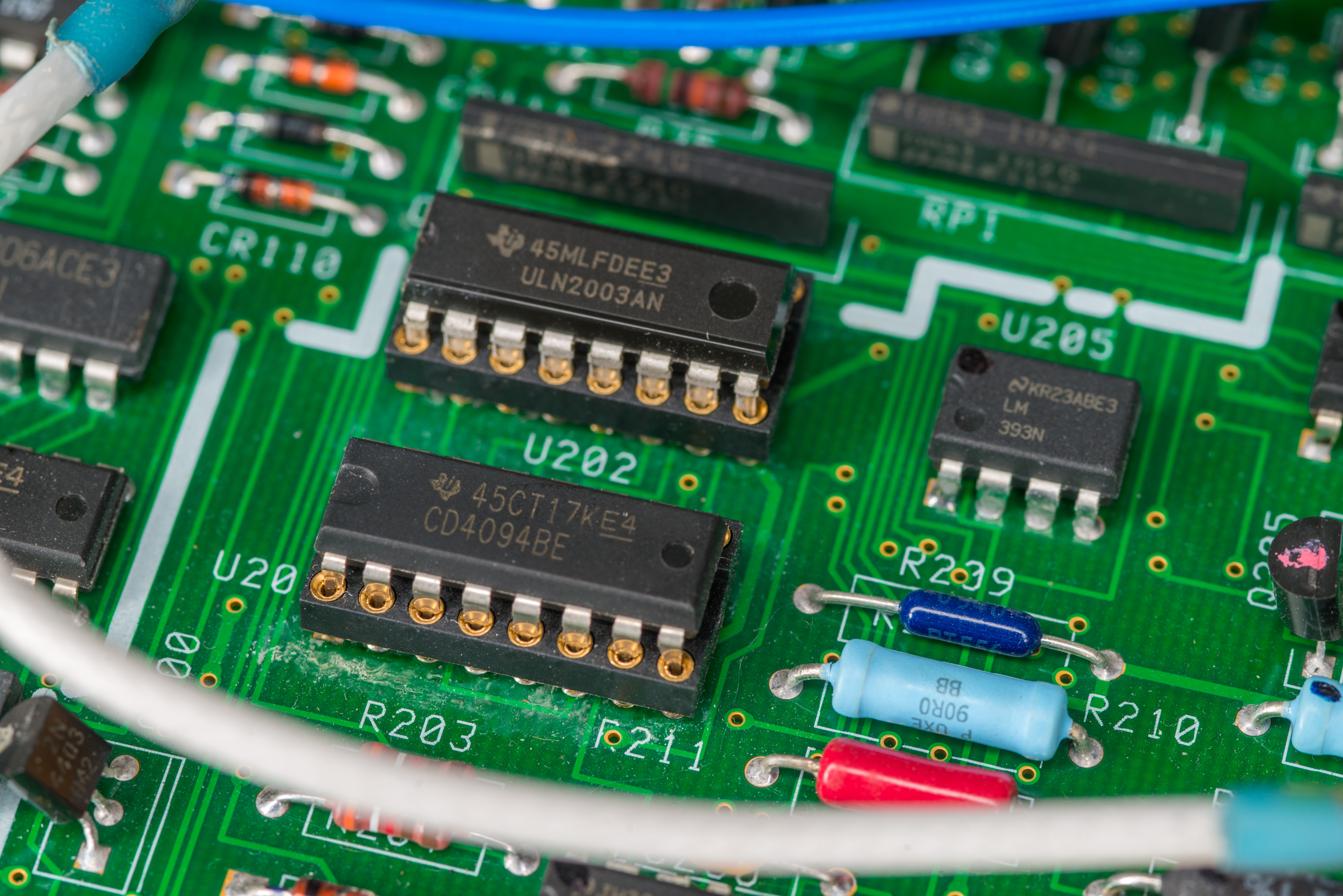
Next I see that two of the chips on positions U200 and U202 are populated in sockets. Due to flux residue on the board I can conclude that sockets were not the original design choice from factory, so somebody else put sockets and new chips in. Perhaps worth to keep this in mind in later troubleshooting.
In future once instrument is restored and tested I might remove the sockets and populated chips directly on PCB, like it supposed to be. CD4094 and ULN2003AN are not sensitive for leakage or contact resistance, so should be ok for now.
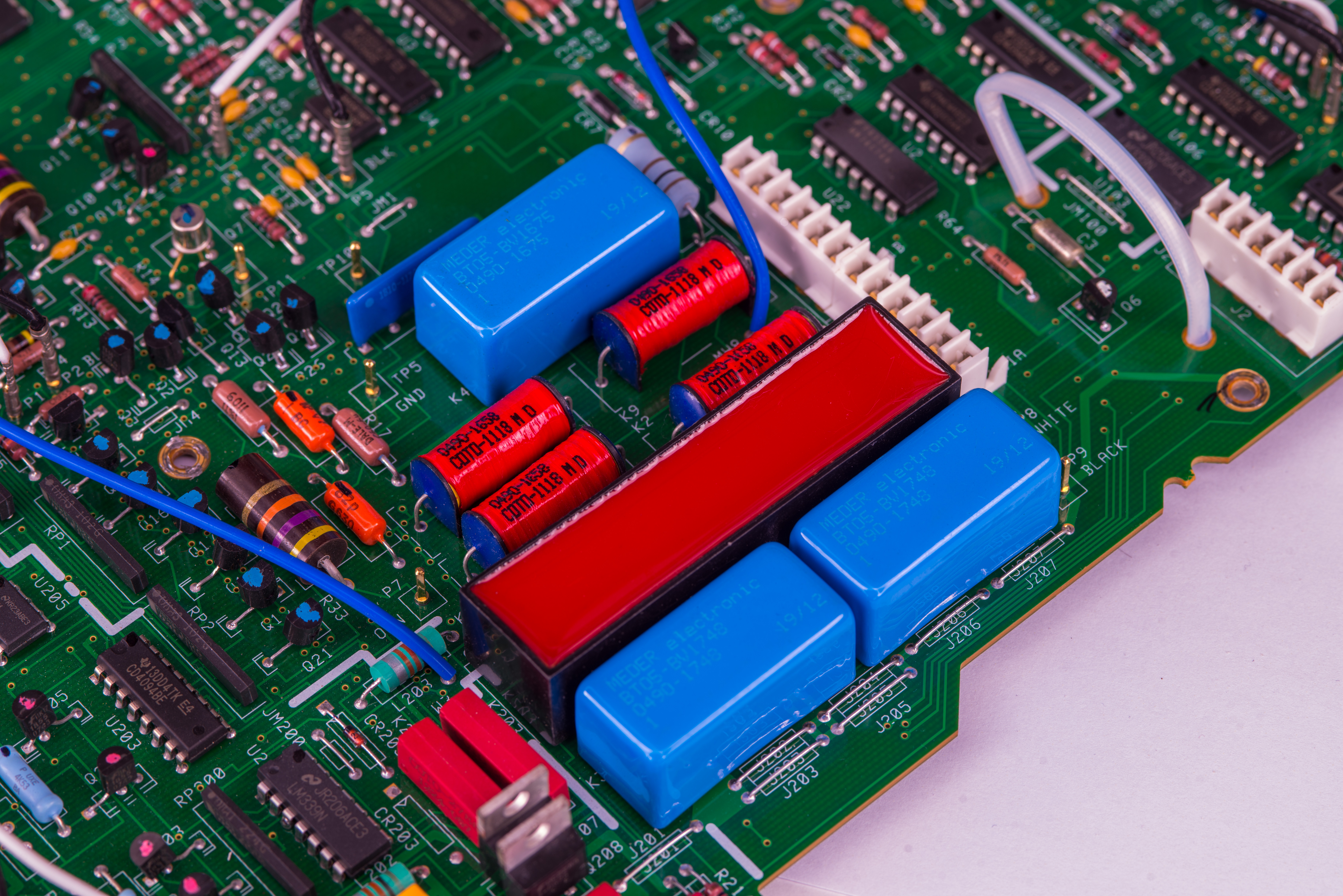
Next interesting difference on this Agilent board are glazed shiny blue Meder reed relays. Just like original COTO 0490-1675 and two COTO 0490-1748 these new blue Meder are no less custom with part-number BT05-BV1675 and BT05-BV1748. BT series relays are specified as low thermal voltage relay, high insulation resistance and high voltage. Index “05” stands for 5V nominal coil voltage and BV code is custom order specification for Agilent.
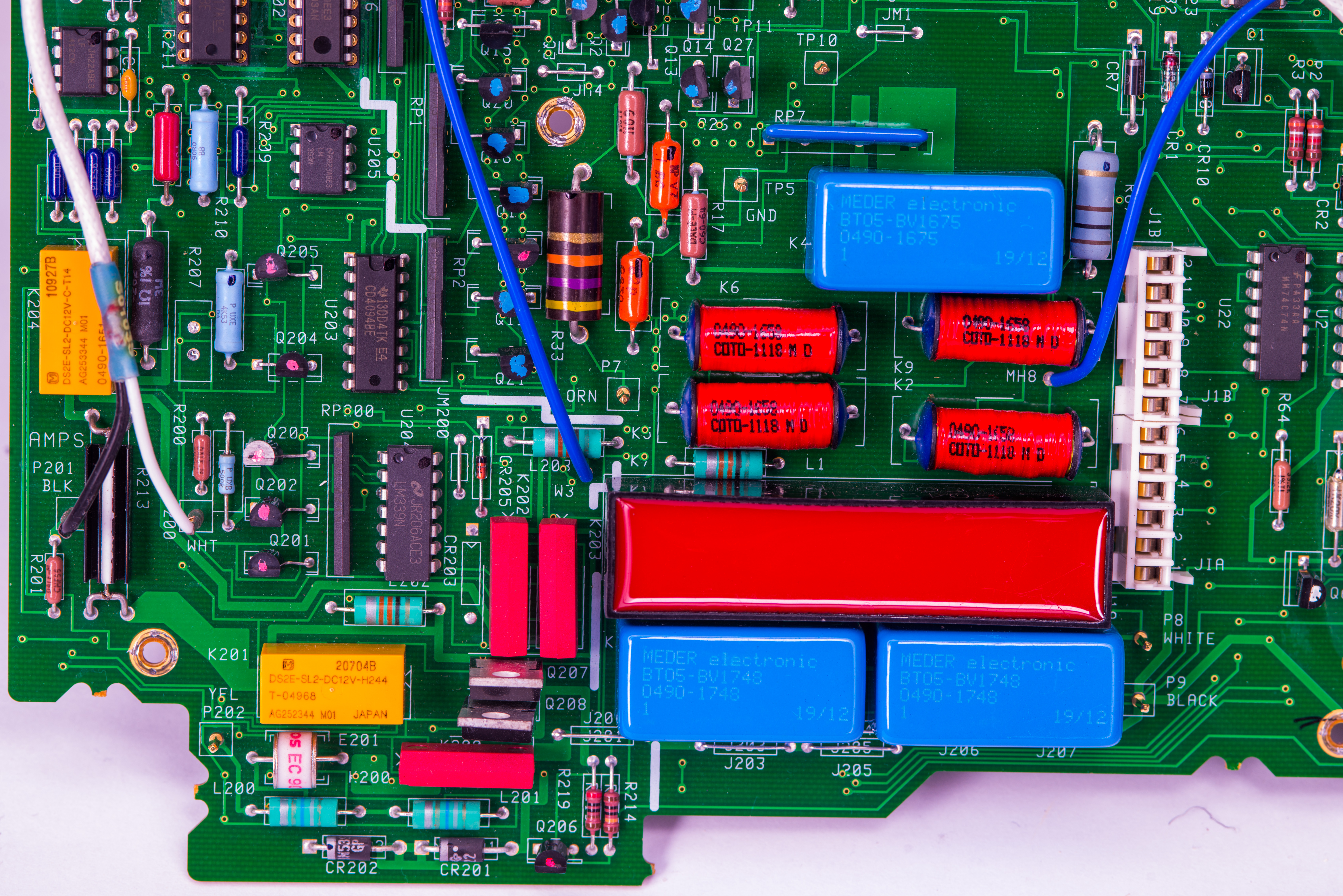
Typical price for similar BT05 relay on retail stores is around $40-50 USD a piece, so not a generic cheap relay. These relays are not latching, making careful contact design even more important due to small but detectable self-heating from the energized coil.
There is also interesting jump-wire, also present on those older HP boards. Now that I believe is a factory modification, together with removed CR203 zener. It was engineering change implemented around year 1993 by HP, when they replaced three black OKI reed relay to red COTO relays.
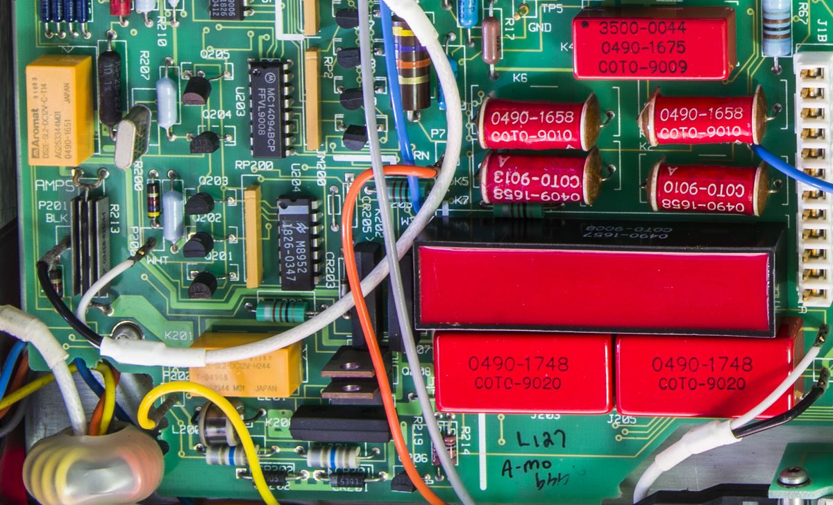
New relays operate at lower coil voltage and to implement drive voltage change coils were connected to digital +5V power node by wire, instead of +13V step down from CR203 zener and +18V rail.
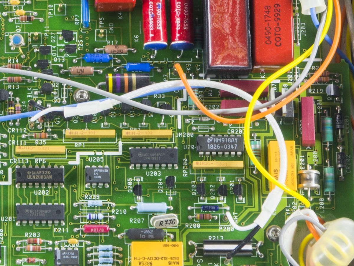
I talk more about that in YouTube video here. It would be interesting to take one of the old HP A1 boards and replace the relays to newer COTO variant, with reduction of drive voltage, while measuring performance of the instrument to compare. These relays are used for DCI/ACI current measurement function where thermal EMF error introduced by switching and multiplexing is particularly important.

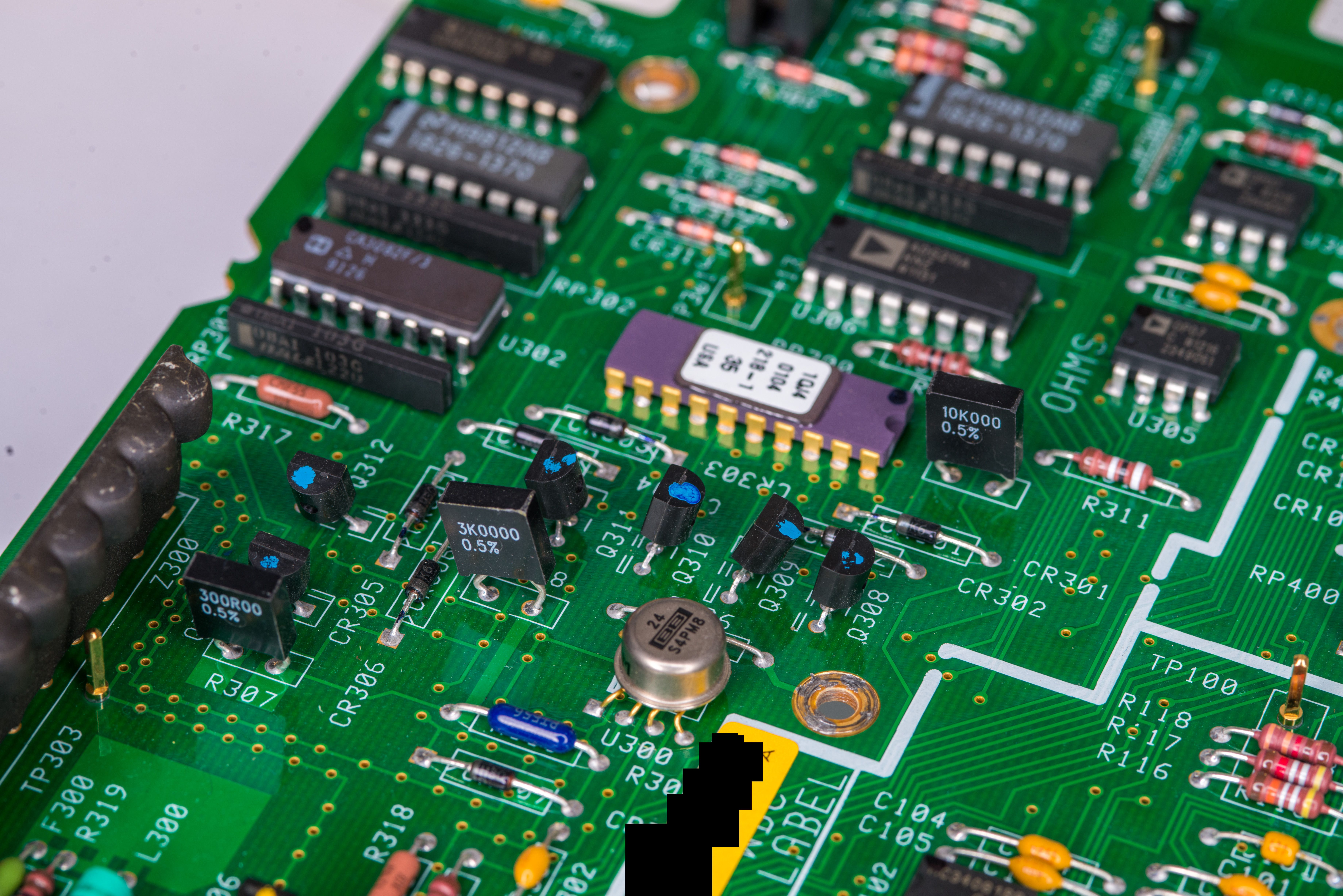
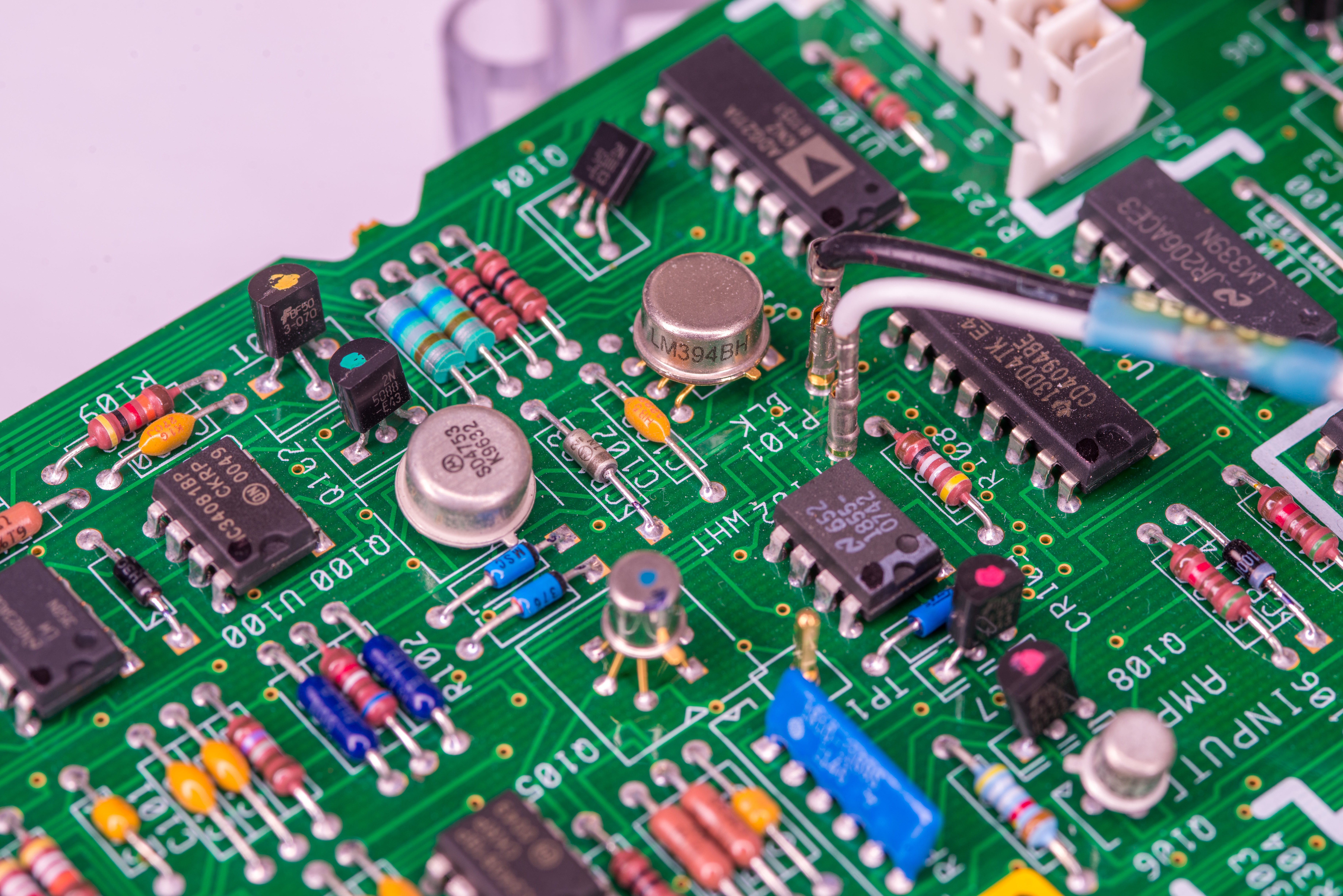
Another noticeable change – mounting method of epoxy foil resistors around resistance function current source. These three resistors now standing up on pre-formed legs, instead of being mounted flush to the PCB like we can see on the old HP A1 DC assemblies.

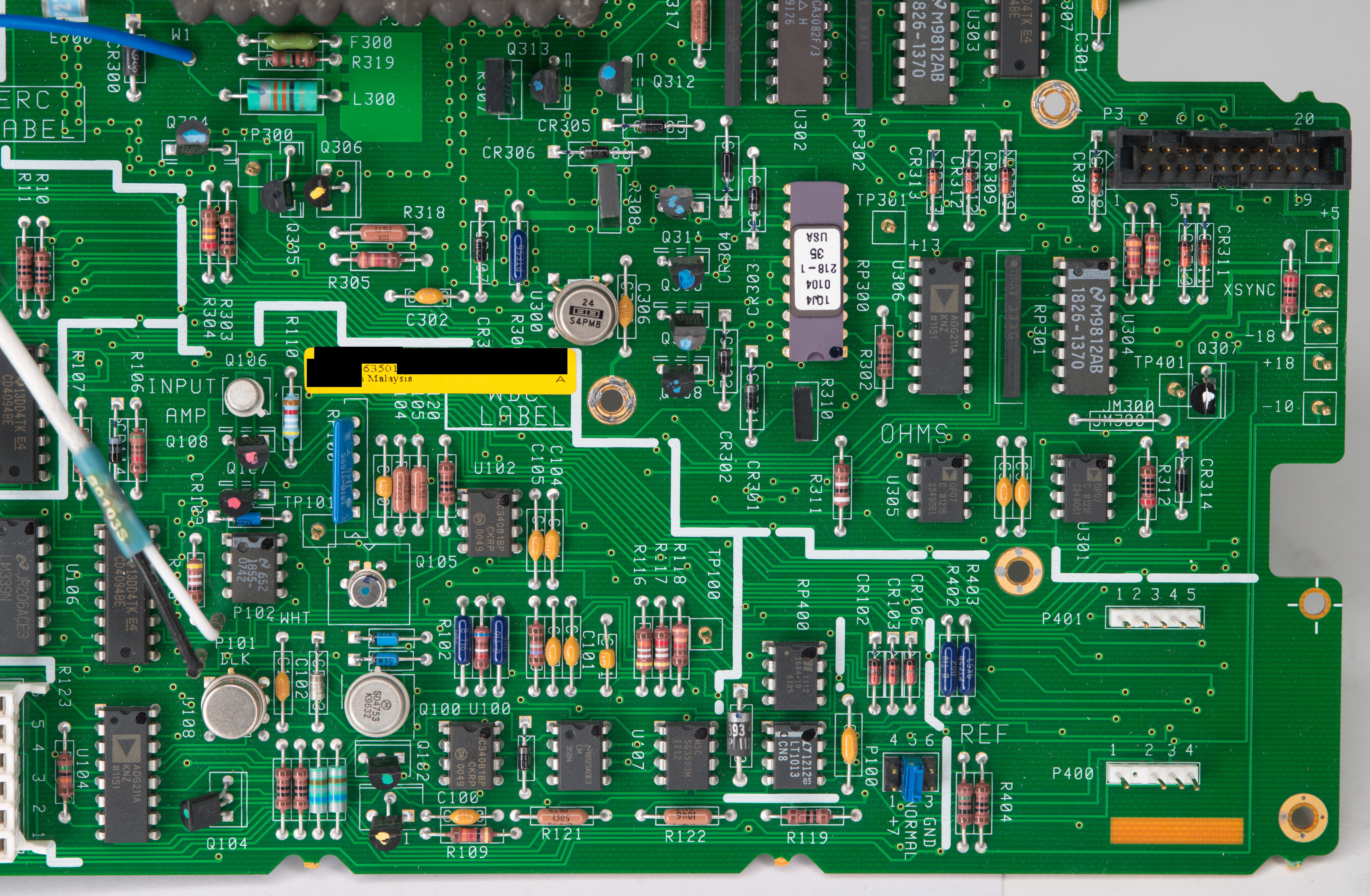


After installing this Agilent A1 board into the instrument first checks reveal clear need of repair. No meaningful readings were obtained from the unit on any of the voltage or resistance ranges. Self-test also failed pretty quickly with “TEST VALUE OUT OF RANGE: 108” error. Similar error with 108 constant also failed during ACAL DCV. Interesting enough that current and 100V, 1kV ranges seem to be working.
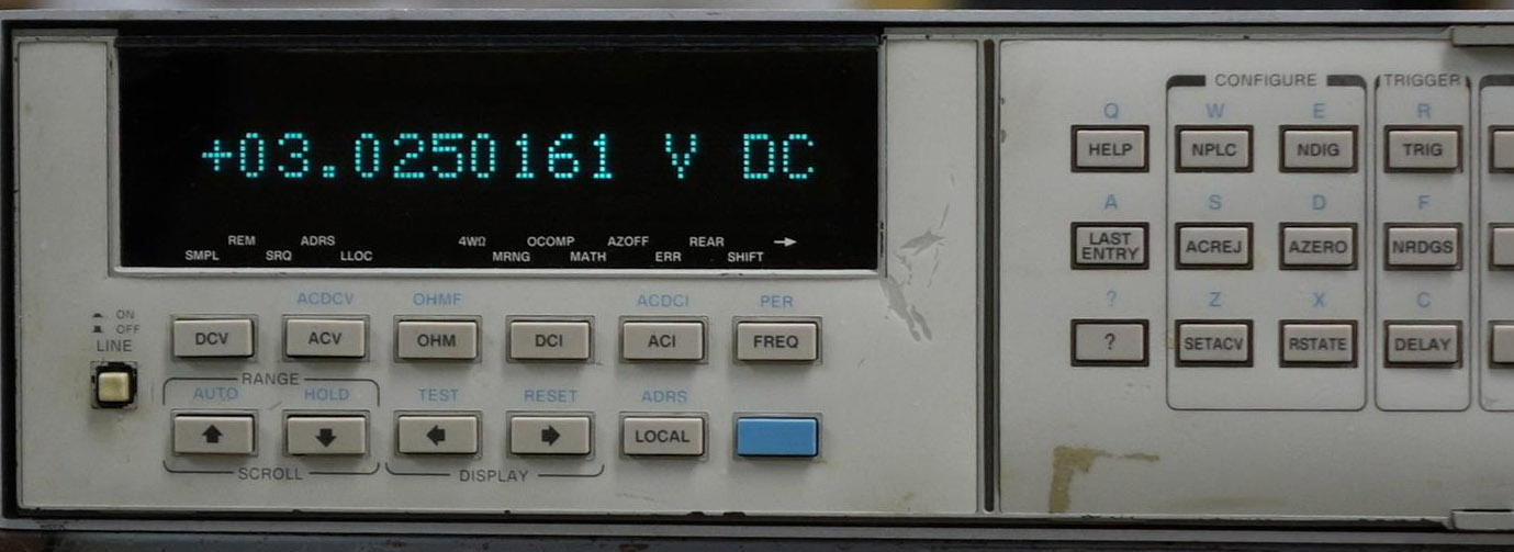
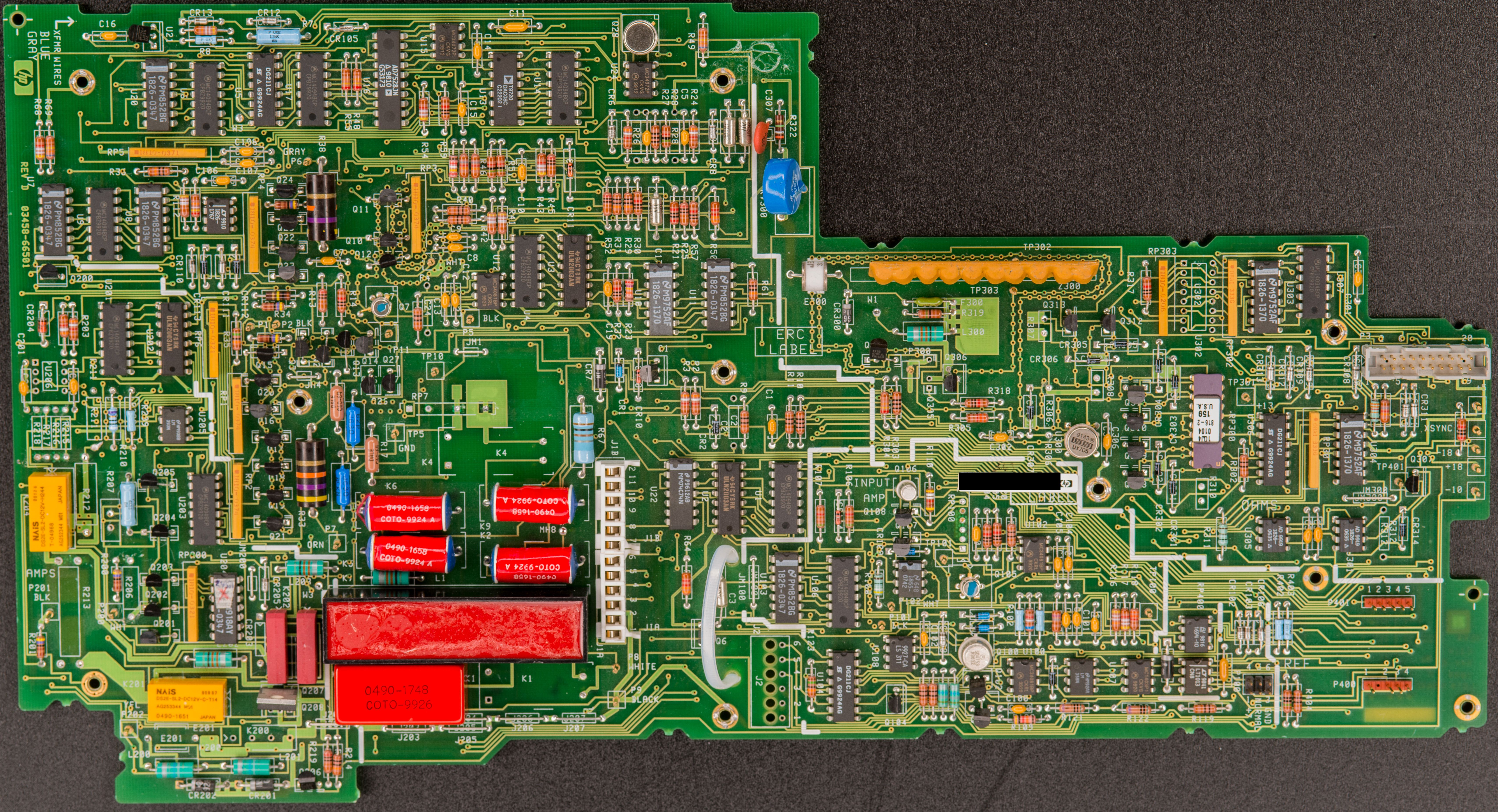
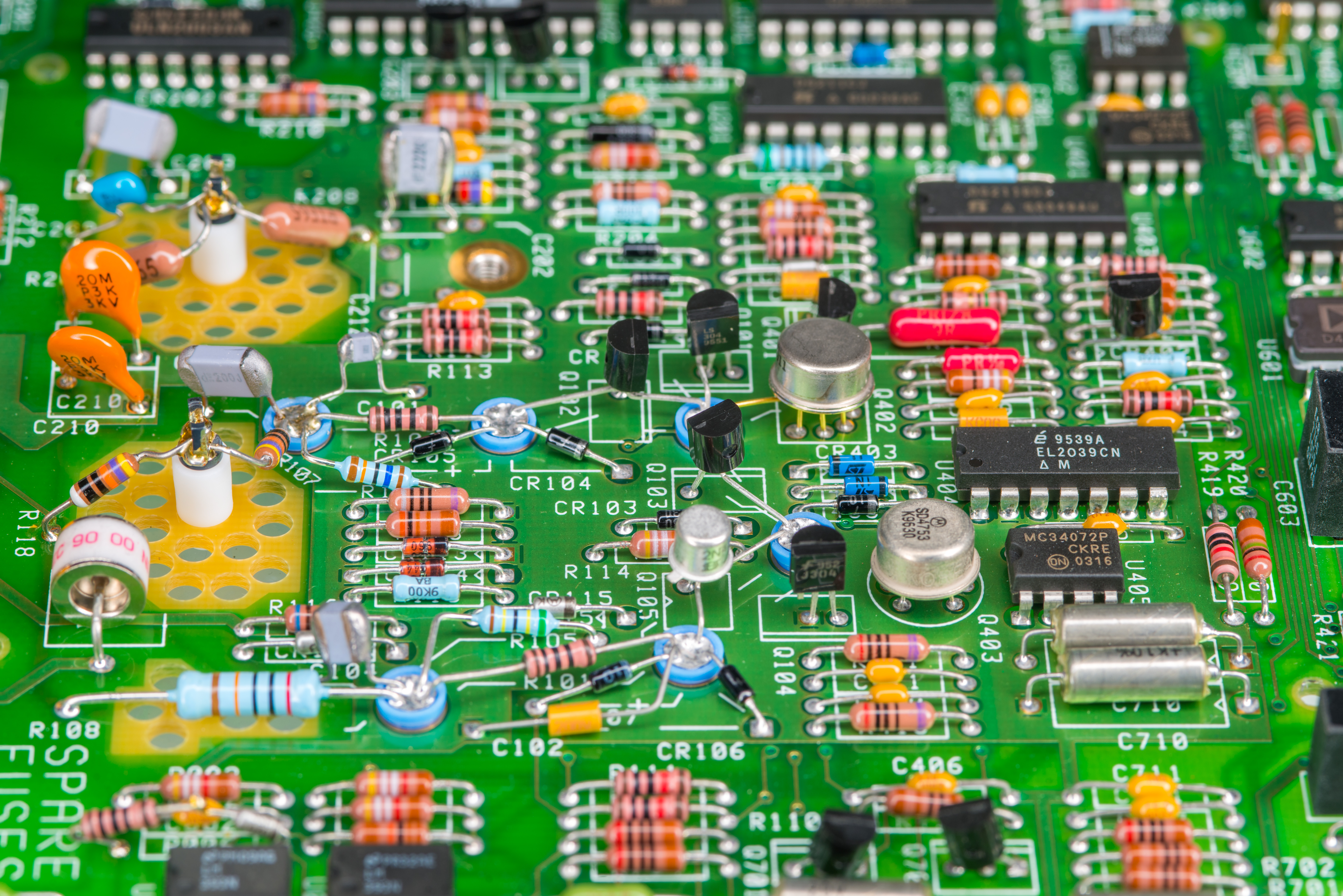
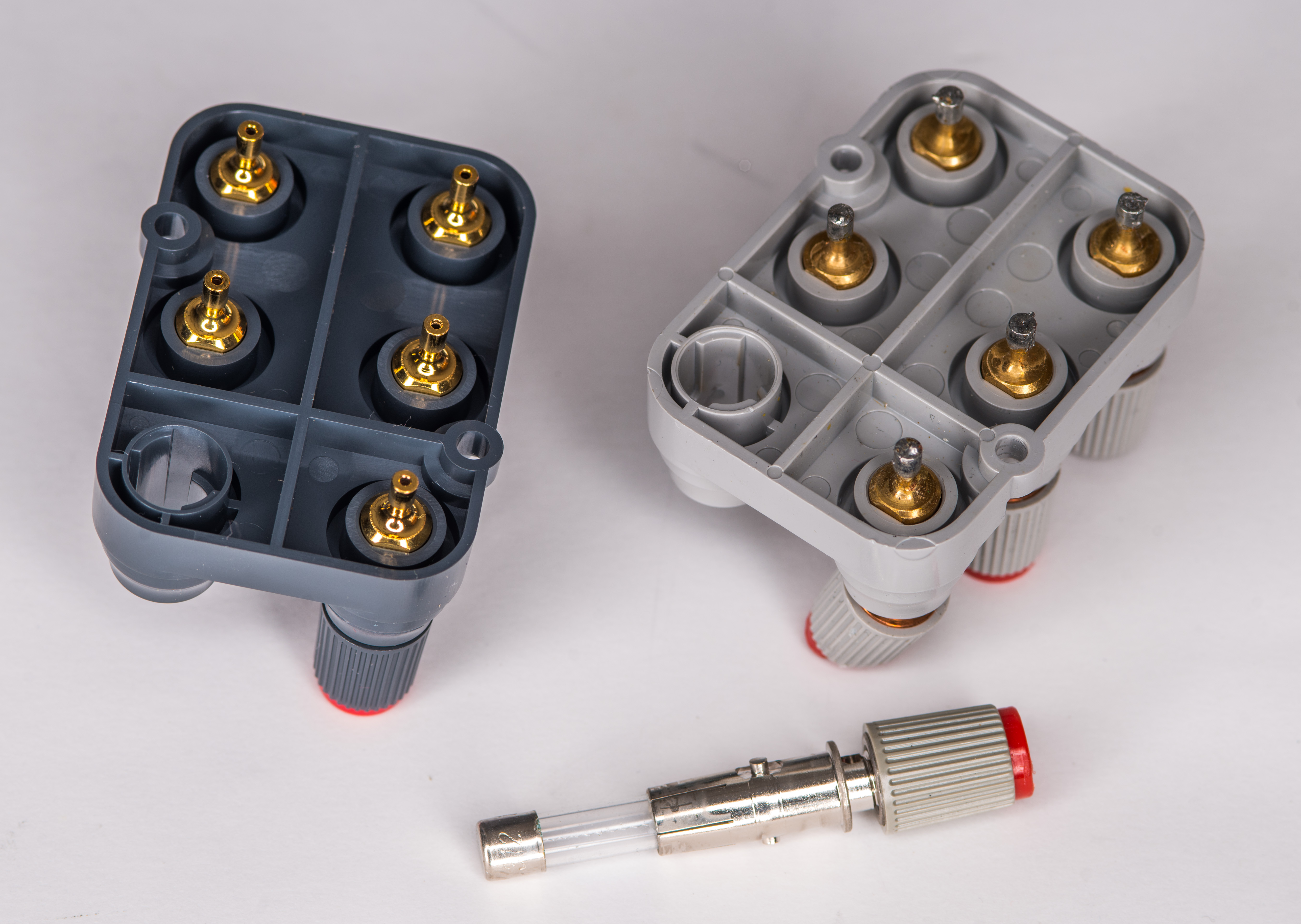
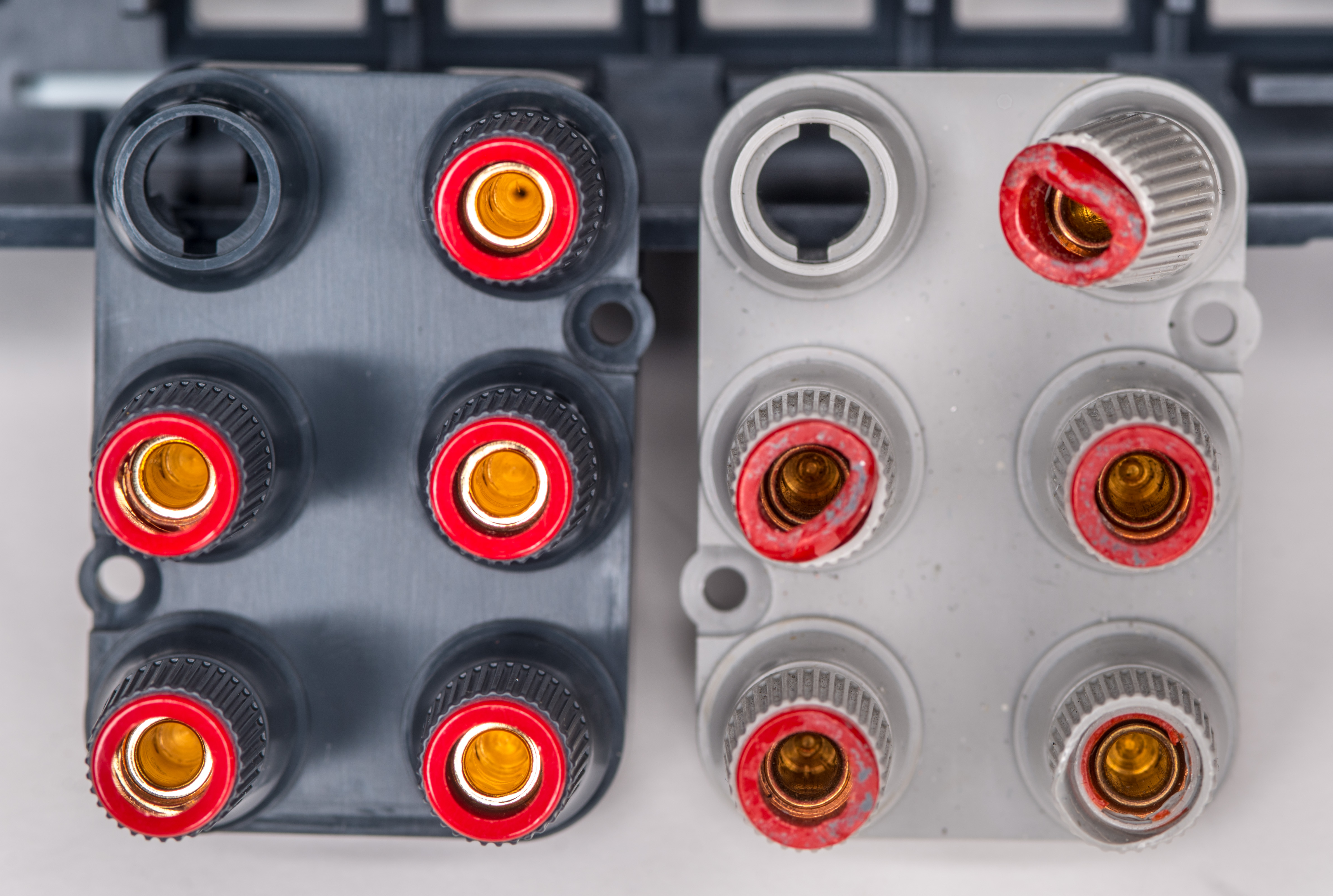
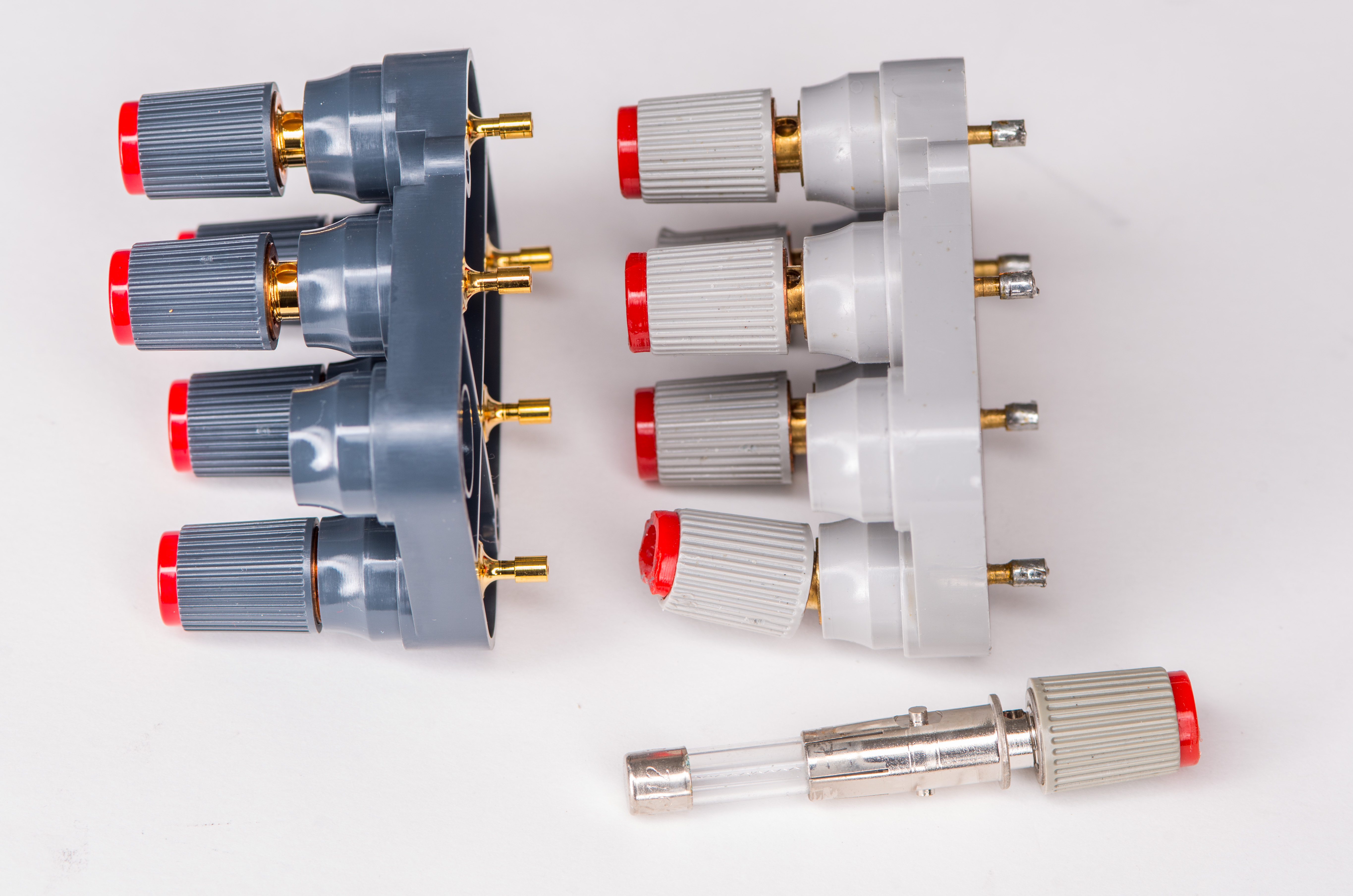
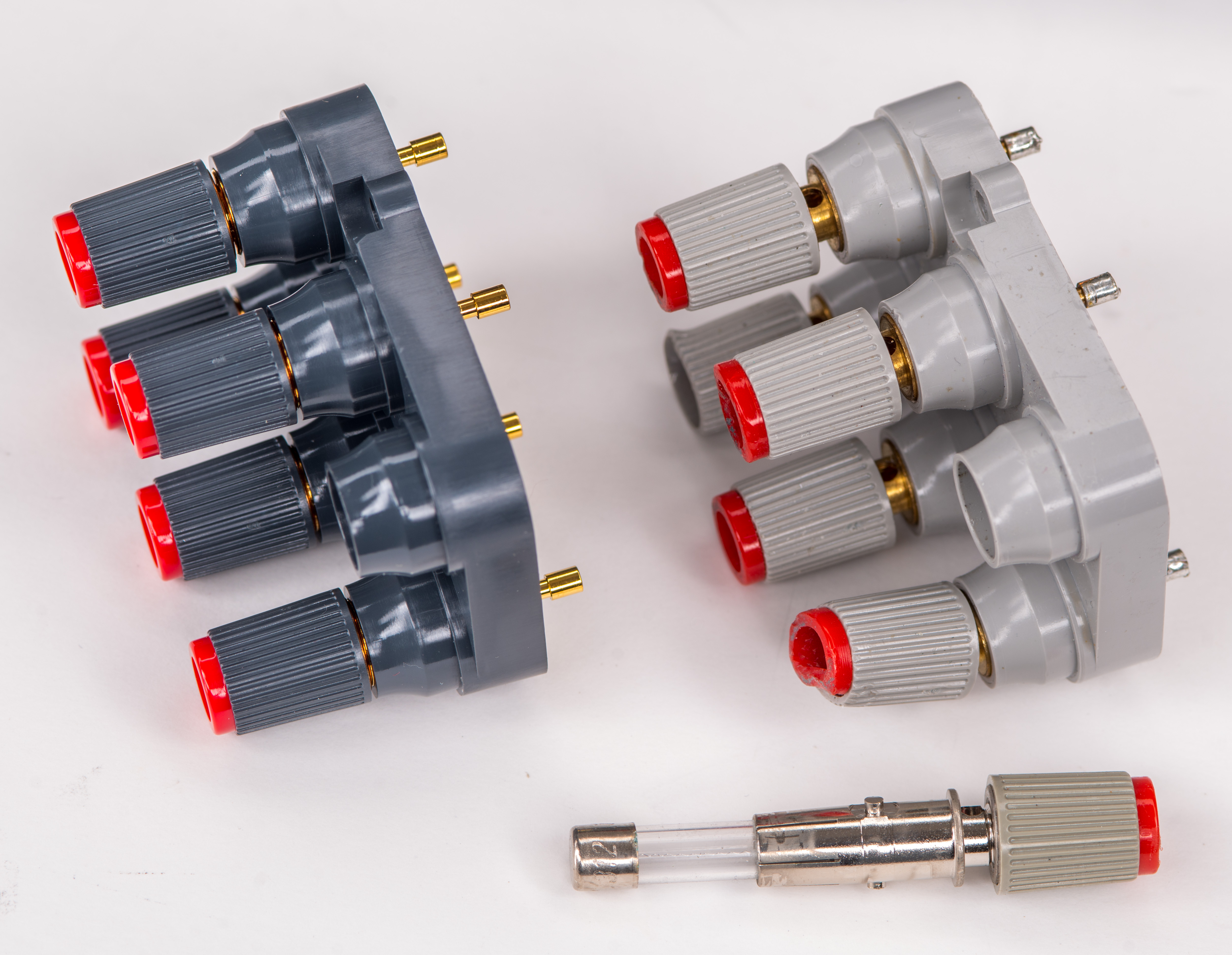
To troubleshoot this fault I’ve connected stable DC voltage source (Keithley 2400 programmed to output +2.0000 VDC”) to the input terminals of 3458A and started probing around A1 with my trusted Keithley 2002 starting from input terminals cable. This method revealed the faulty part in less then 10 minutes, pointing at protection resistor R17.
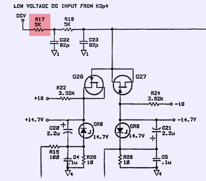
This resistor with nominal value 5000 Ω is installed in series with R19 and two 82 pF capacitors C22,C23 in the main DC path. With faulty R17 reading open (resistance over 1 gigaohm) it is no wonder than none of the base functionality worked. Replacement of R17 with same type and model part from donor A1 board fixed the issue and this A1 able to complete full self-test and ACAL ALL procedures.

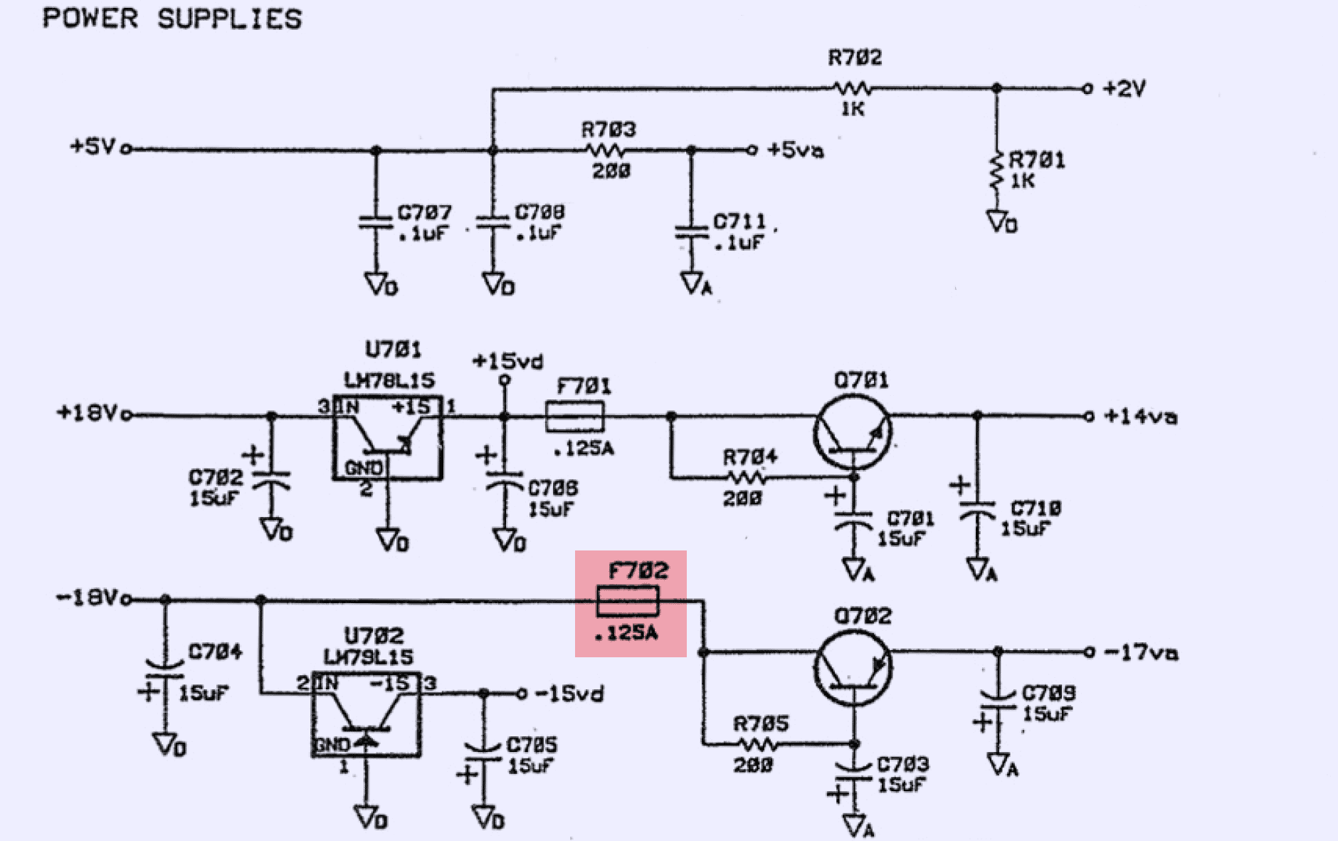
A4 In-guard power supply board
A4 is providing power to all isolated analog circuits and boards in 3458A. It is powered from separate windings of the power transformer and has linear regulators to provide +5, +18 and -18VDC. Also loosely regulated -21 VDC rail generated for use within auxiliary circuits on A1 PCBA. This rail protected by 65mA fuse F1.
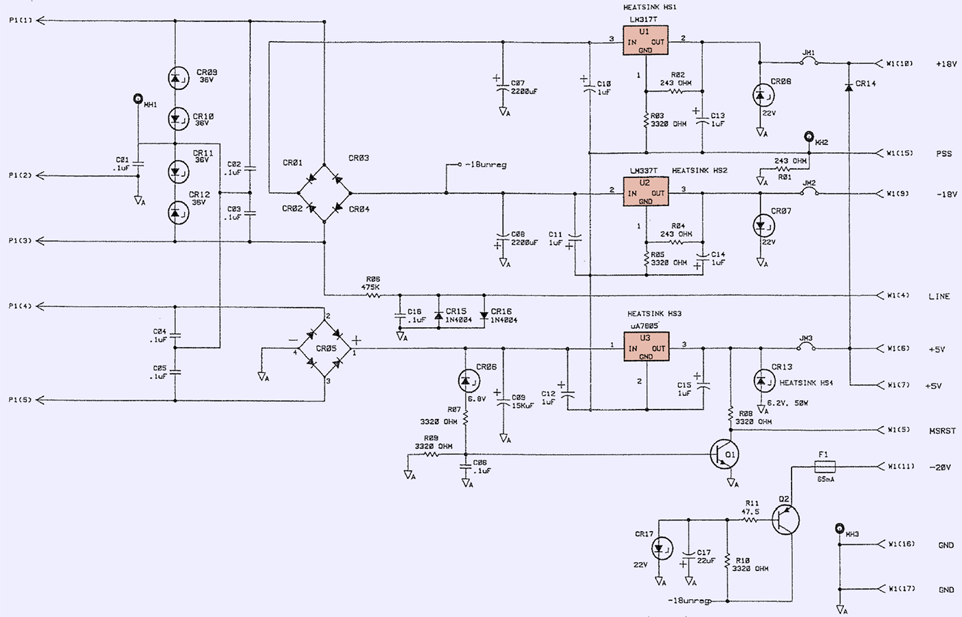
Circuit board is designed with 2-layer FR4 PCB and generate some heat since it is 100% linear. This board is placed right in front of chassis fan to provide good thermal management in the instrument.
This module is actually only PCB that did not any repairs. This is because it was a spare board from one of the previous 3458A units.
Electrolytic capacitors in this PCBA were replaced with new modern components, just to make it slightly more interesting. I don’t expect any performance impact from this, but hopefully bit more reliability since new caps are +105 °C rated instead of +85 °C.

Capacitors that were replaced are located in position C07, C08, C09 and C17.
A2 AC board repairs

Next step is to repair nasty A3 drift.
A5 CPU controller board repairs
A5 board designated to be used in this instrument has a “blinking cursor” issue and missing ROM/RAM chips in addition to stolen oscillators. This section is documented on video below.
A3 A/D converter repairs
No doubt A3 assembly is the heart of the 3458A performance. To try something new I’ve took one of bad drifting boards and baked to real well done condition. It was decided that in worst case I’d still have broken board and not loose anything except time. In best case we could obtain some interesting data if baking humidity out of the board change anything in behavior.
Obviously all plastic components like connectors, fiber transmitter/receiver need to be removed before whole board is heated up. Video showing reinstalling all parts and swapping damaged tantalum axial capacitors shown here:
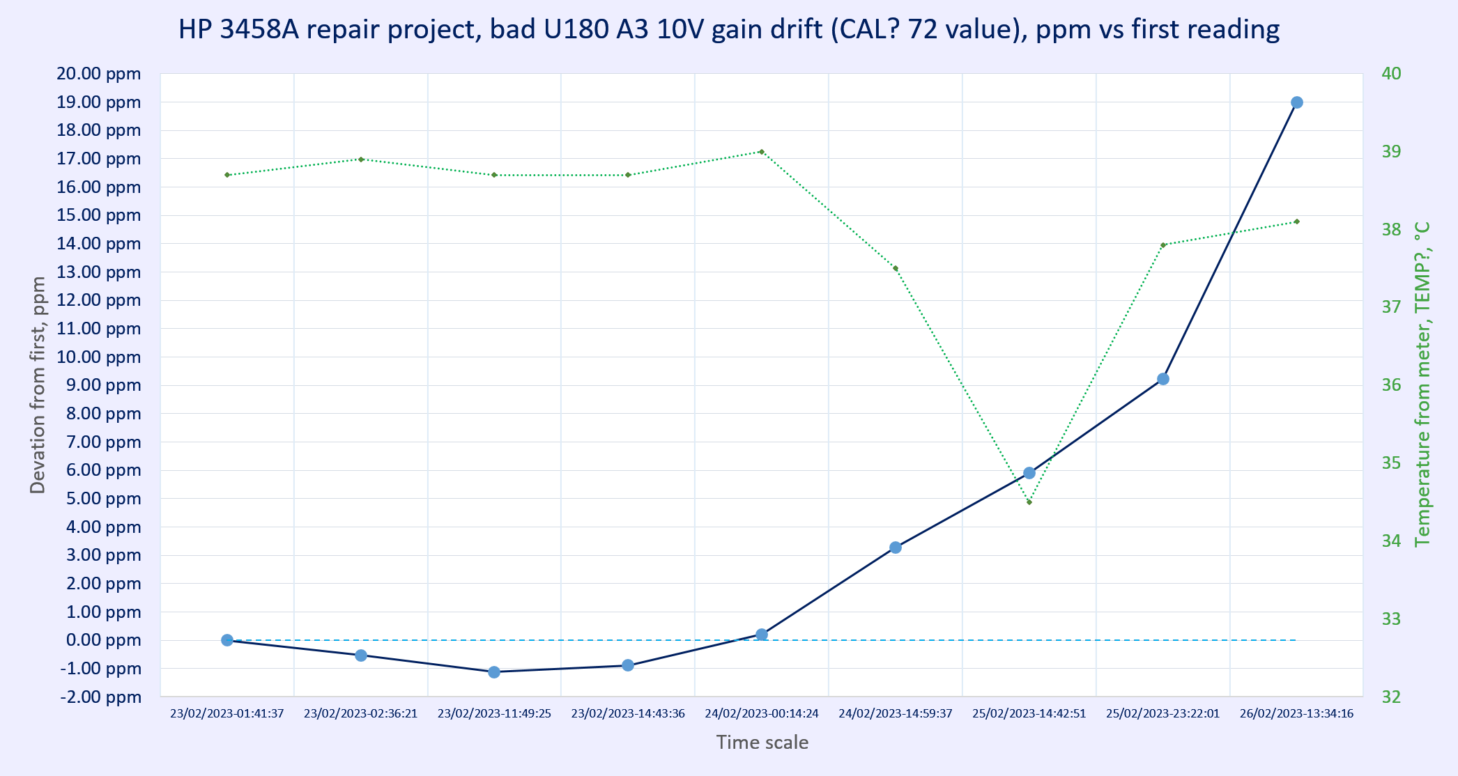
August 2023 update on A3 stability
After logging previous A3 A/D assembly board performance significant drift down was observed:
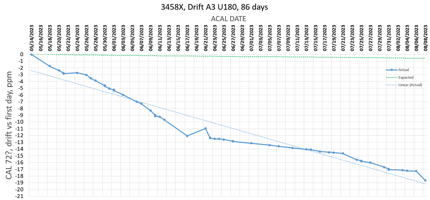
Observation span was 86 days, and CAL? 72 constant (10V gain) drift kept going steady down, with large -0.22 ppm/day slope, which is unacceptable for good performance of 3458A DMM. Expected good A3 assembly would have drift less than ±0.01ppm/day. So this A3 board is rejected and I decided to repair yet another A3 drifter, one with interesting failure mode.
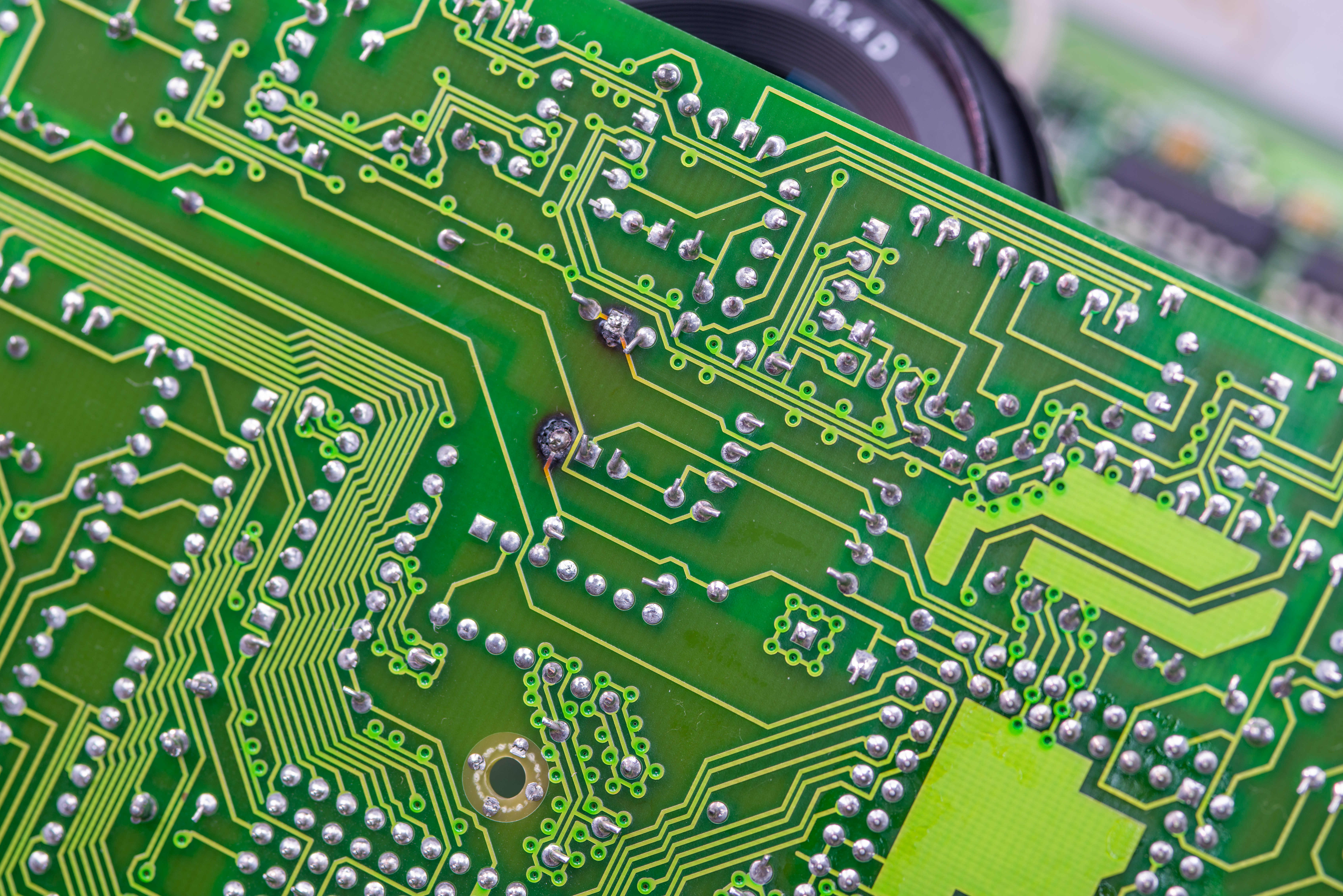
A3 in question had pin 52 of U180 (+4.5V power rail for logic chip) shorted to ground with <0.02 Ω resistance. This voltage is provided by small power zener and resistor at A3, which immediately cooked themself upon test power up before.
So other that bad U180 I’ve also needed to repair burnt damage around zener pins and replace original zener. Few hours later and photos of progress after repairs available below.
Charred FR4 material was milled out with dremel and end-mill tool and damaged connections were replaced with jump-wires.
I was also curious if U180 die is visible damaged so applied some power of Thor to get it crack open.
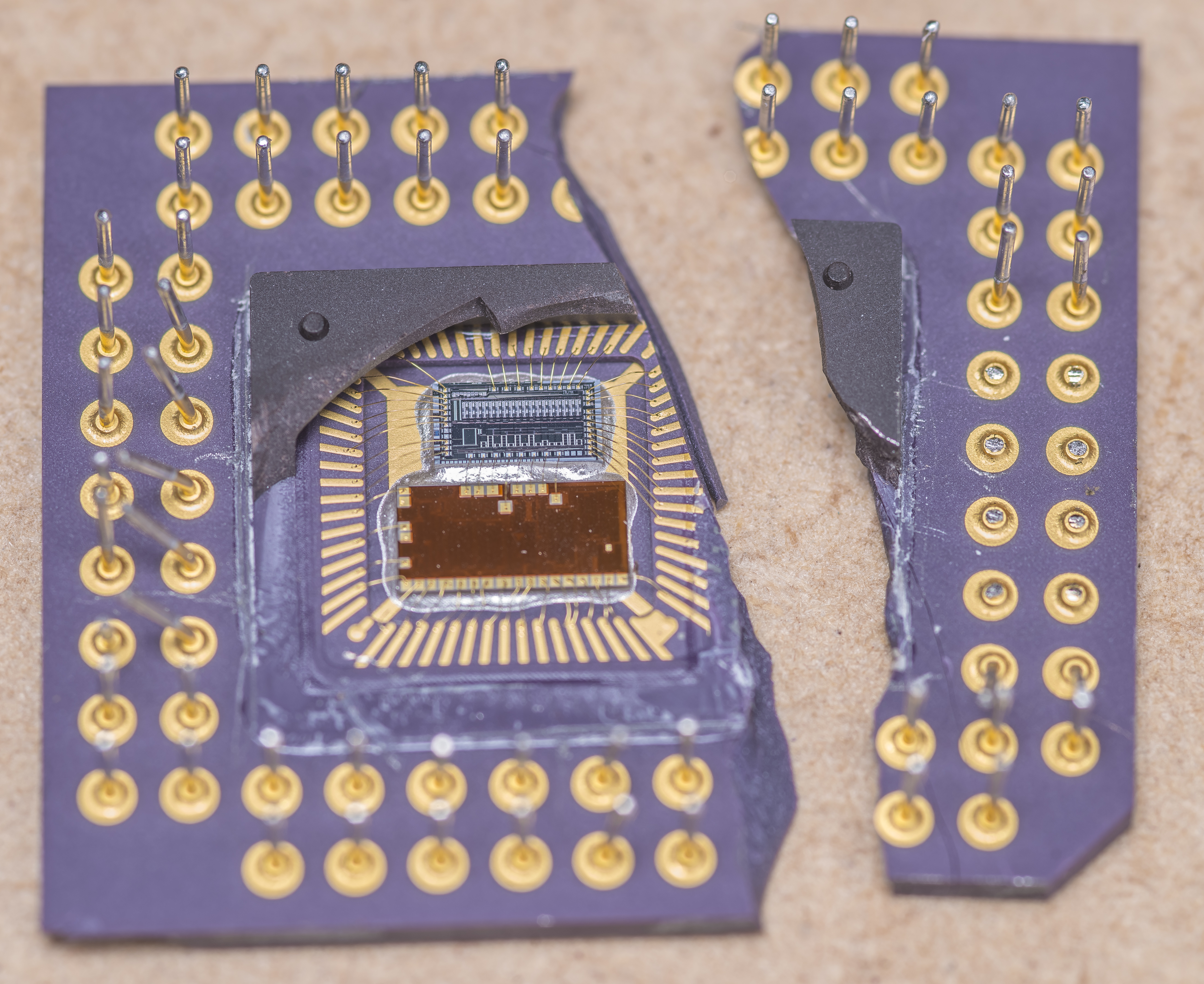
Dies and all but one wirebonds are still intact so we can take closer look under microscope later on.
Benchmarks and tests of restored DMM before any experiments
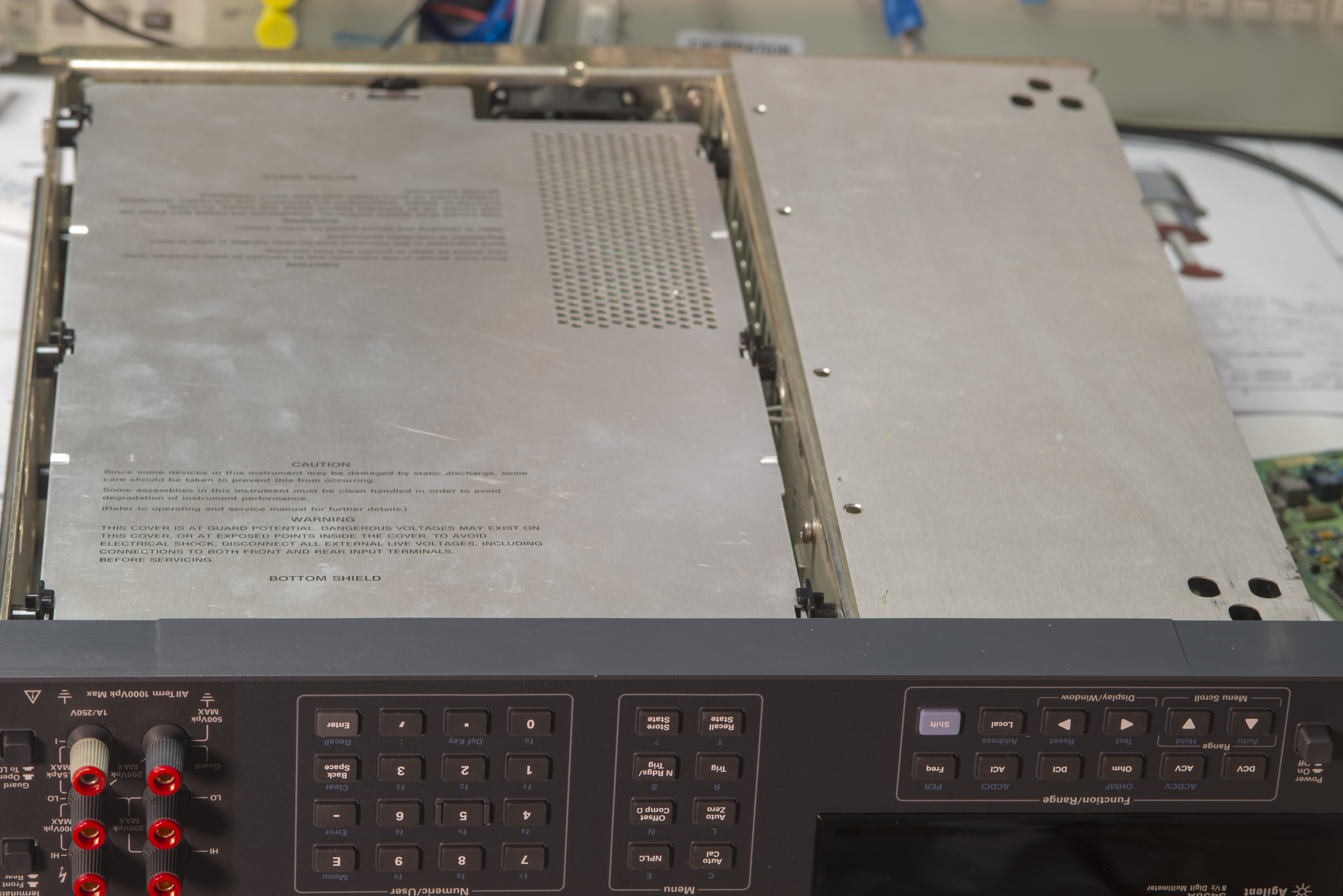
Special option for additional outguard shields
There was special US Navy option available from HP/Agilent/Keysight to have additional aluminum shields installed over the outguard boards, to help instrument pass military EMI/RFI standards. I have acquired set of these shields for some experimentation some years back. They are rather thin aluminum sheet metal with mount points to the steel chassis frame holes on both sides.
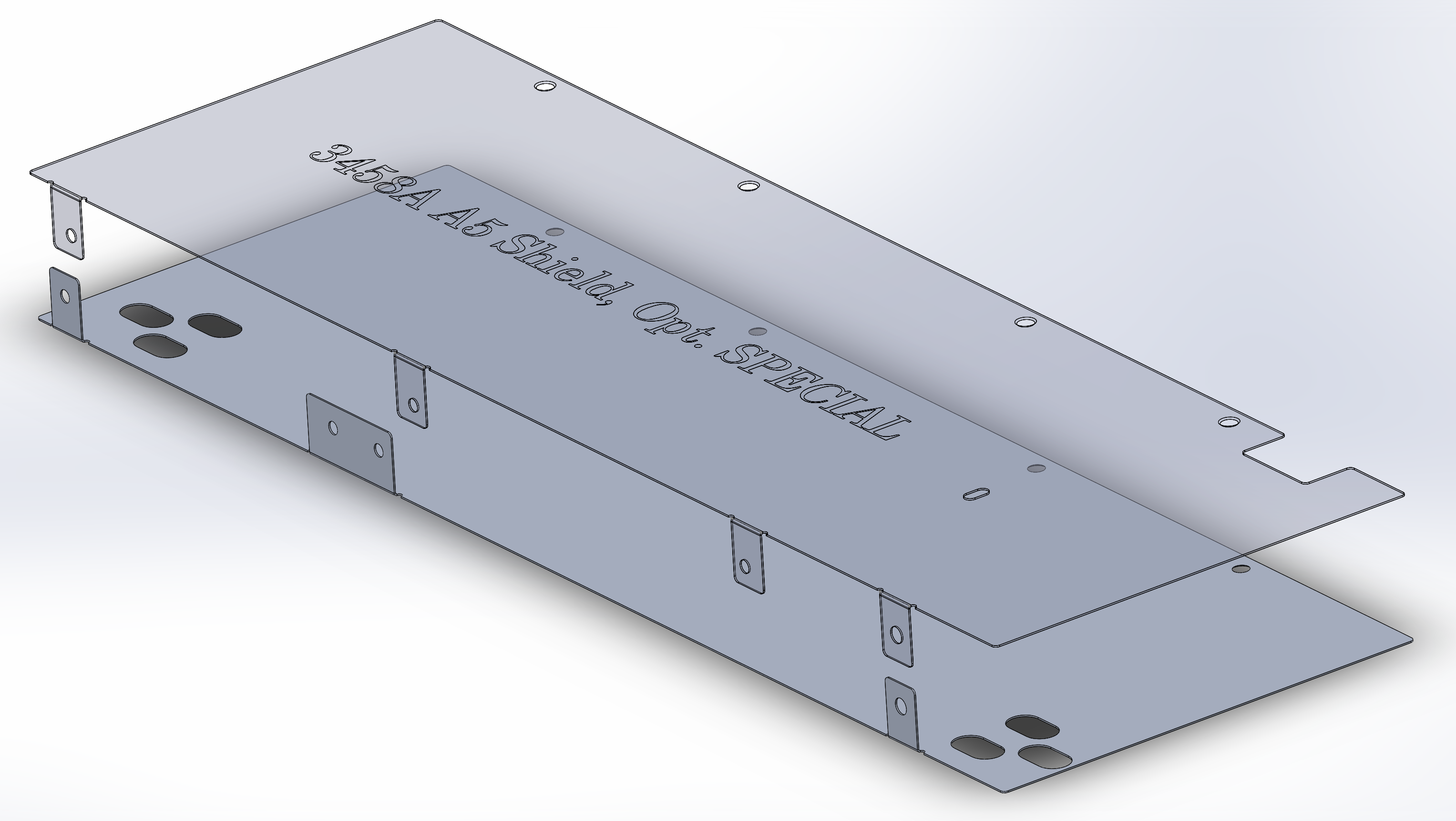
Image 59: Render of two option “SPECIAL” shields for US Navy 3458A
Below are photos of how these shields look like on one of my older 3458A units for reference.
p=.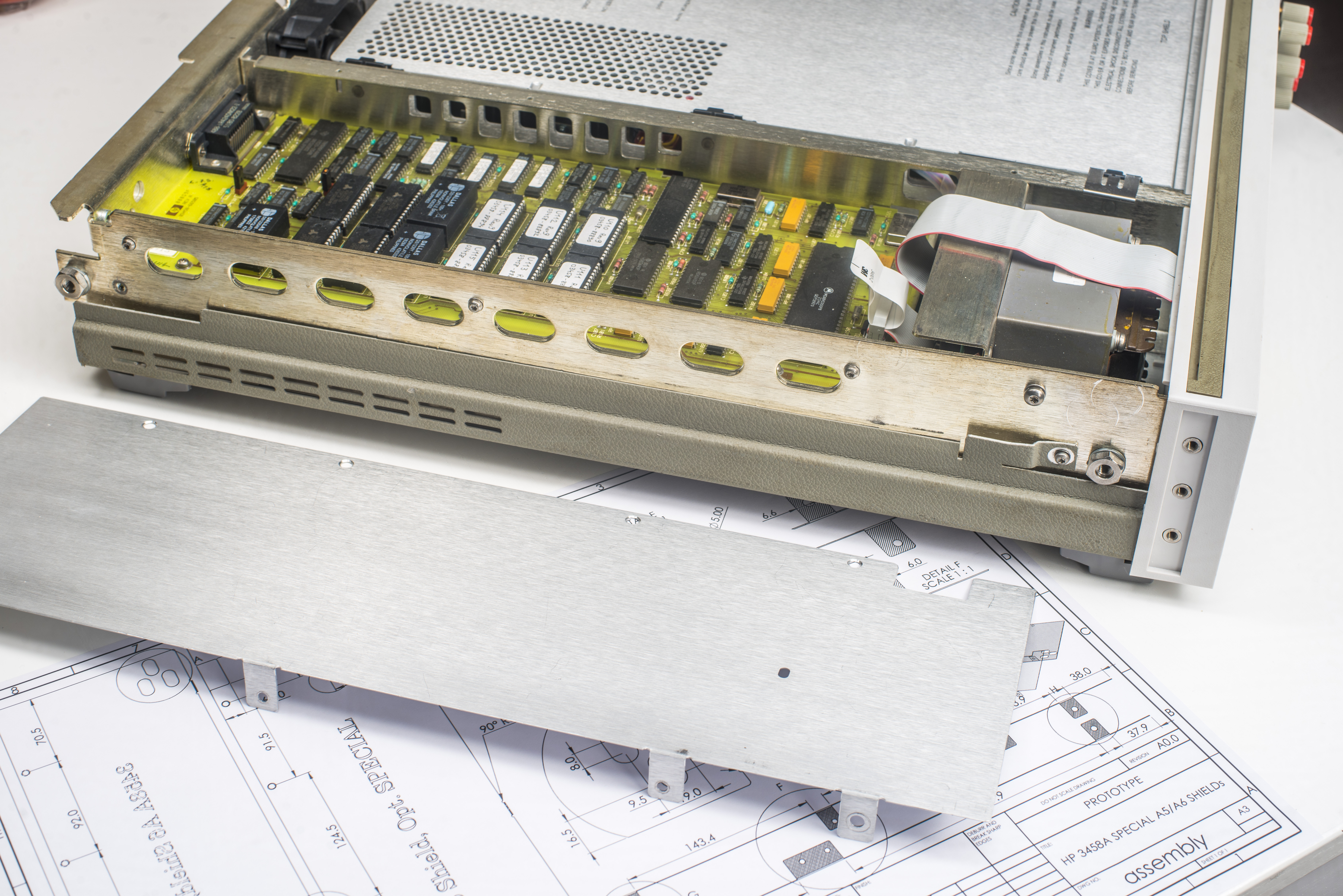
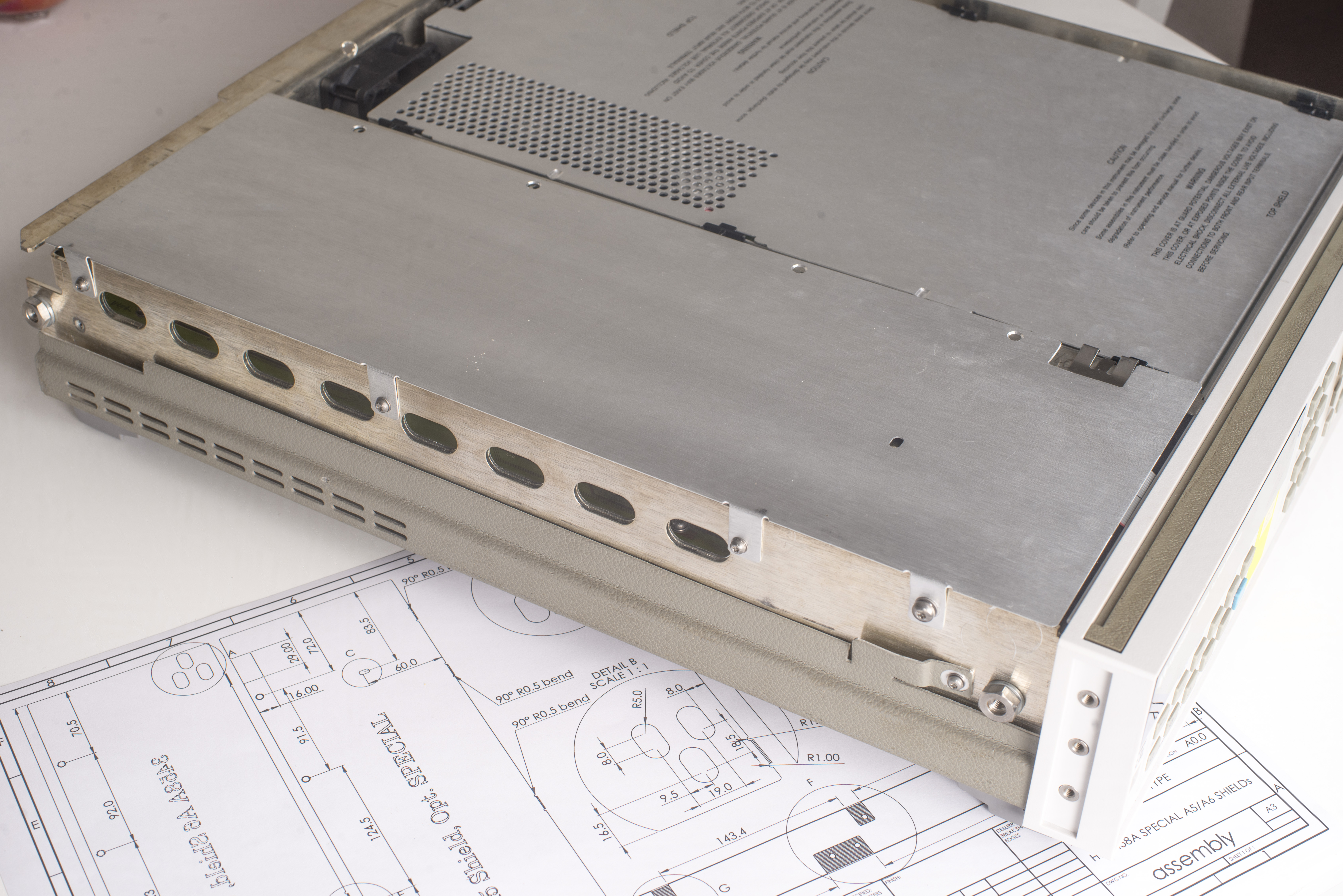
Image 55-55: Top side special shield installed in older 3458A unit
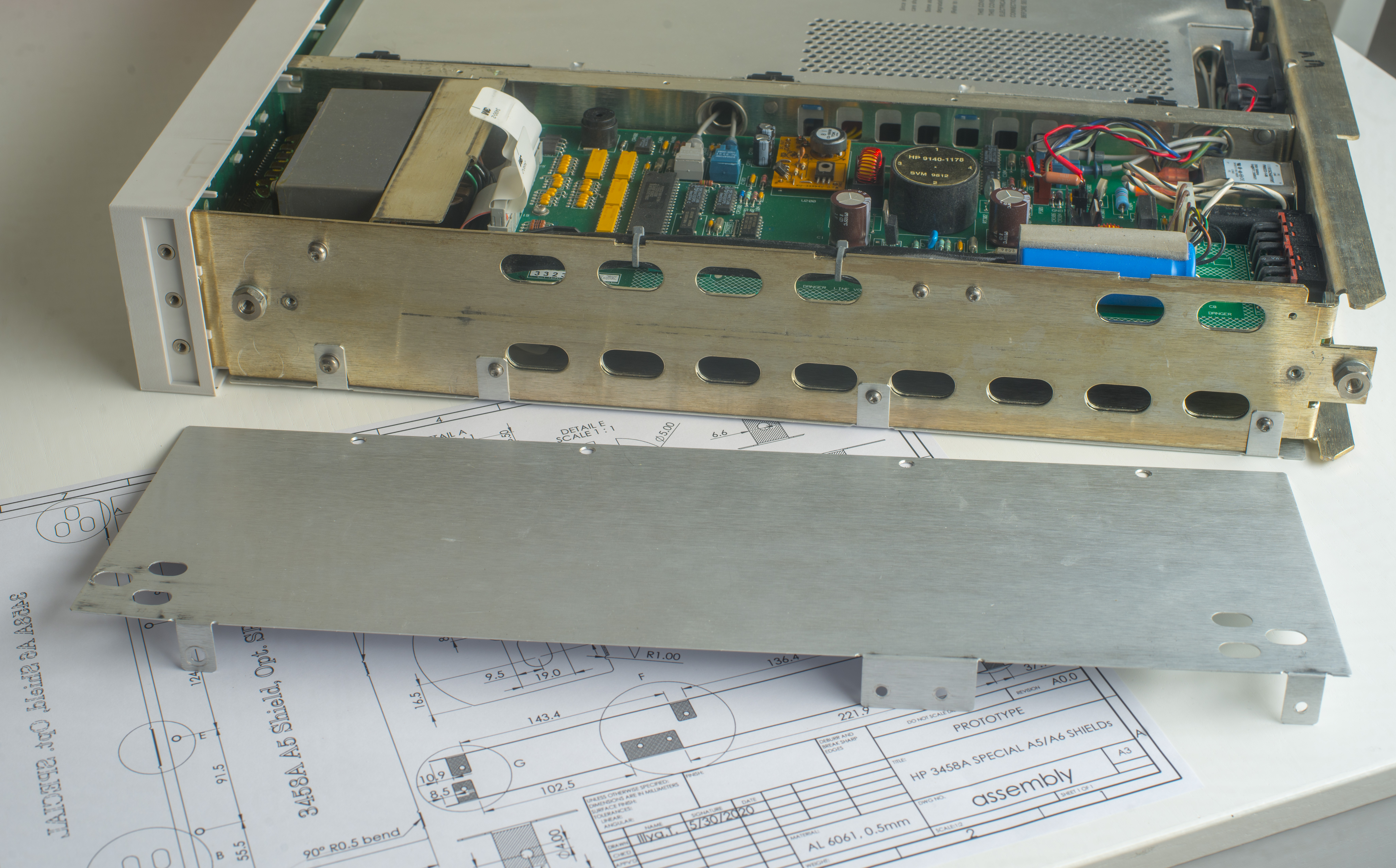
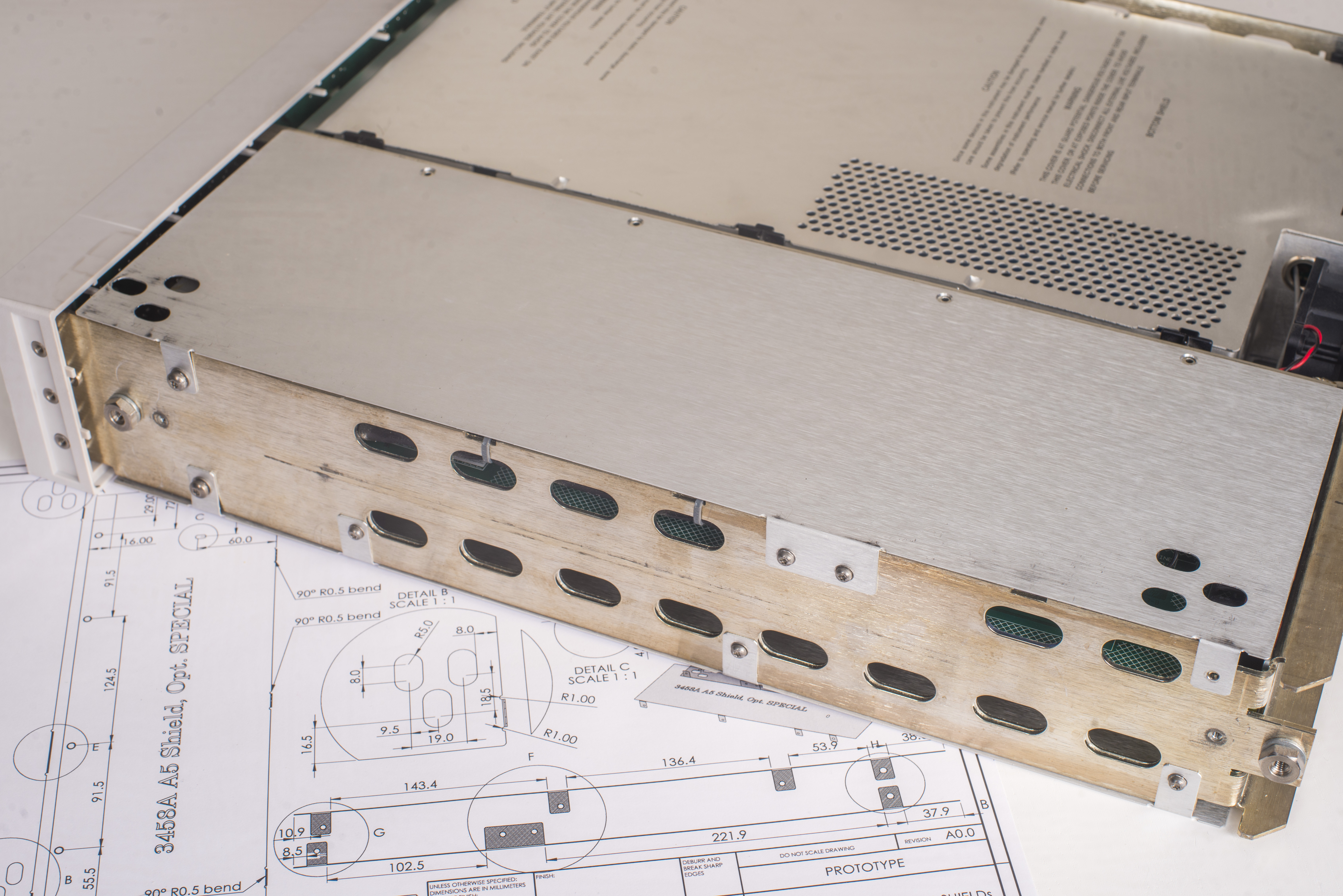
Image 59-55: Bottom side special shield installed in older 3458A unit
These shields are not necessary to meet standard published 3458A specifications, hence none of the standard units have them installed. You also cannot buy these shields from the Keysight separately as a part. It will be interesting to see if these shields actually matter for any sensitive measurements in future.
Lower noise A9 voltage reference PCBA with new ADR1000 6.62V zener chip
This is a combined modification of both hardware and firmware of the 3458A. Hardware part is easy enough, just take original HP A9 PCBA, replace LTZ1000A with Analog Devices ADR1000, replace resistors to match the new ADR1000 requirements and reinstall the modified module back onto A1 PCBA. Hardware part at this step is finished.
However to make the meter fully functional with much lower voltage zener reference chip we need to allow lowest limits for acceptable reference voltage from 7.1V down below 6.6V. Without this step meter will not be able to complete ACAL and unable to self-adjust all the ranges and functions.
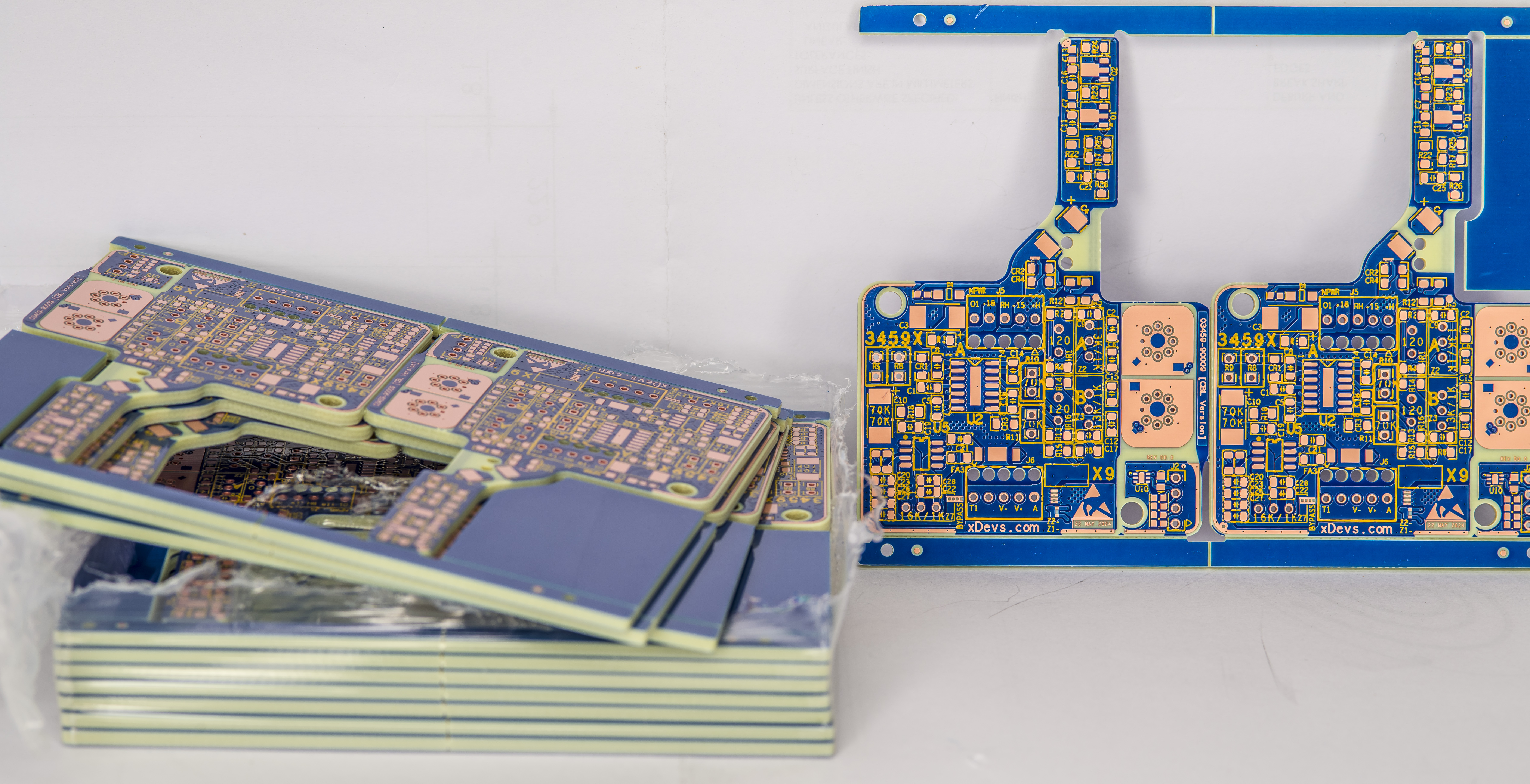
Original HP-designed A9 PCB module is not the best choice to push for lower noise zener implementation, so I’ve decided instead to build own custom zener core module as a plug in replacement. This way we can easily swap different reference modules and maintain capability to revert the instrument to original LTZ1000A A9 at any time in future. This is especially handy for newer ADR1000 chips which exhibit a lot of initial drift in first few years , compared to the older yet still undefeated LTZ1000A product (in terms of long-term stability).
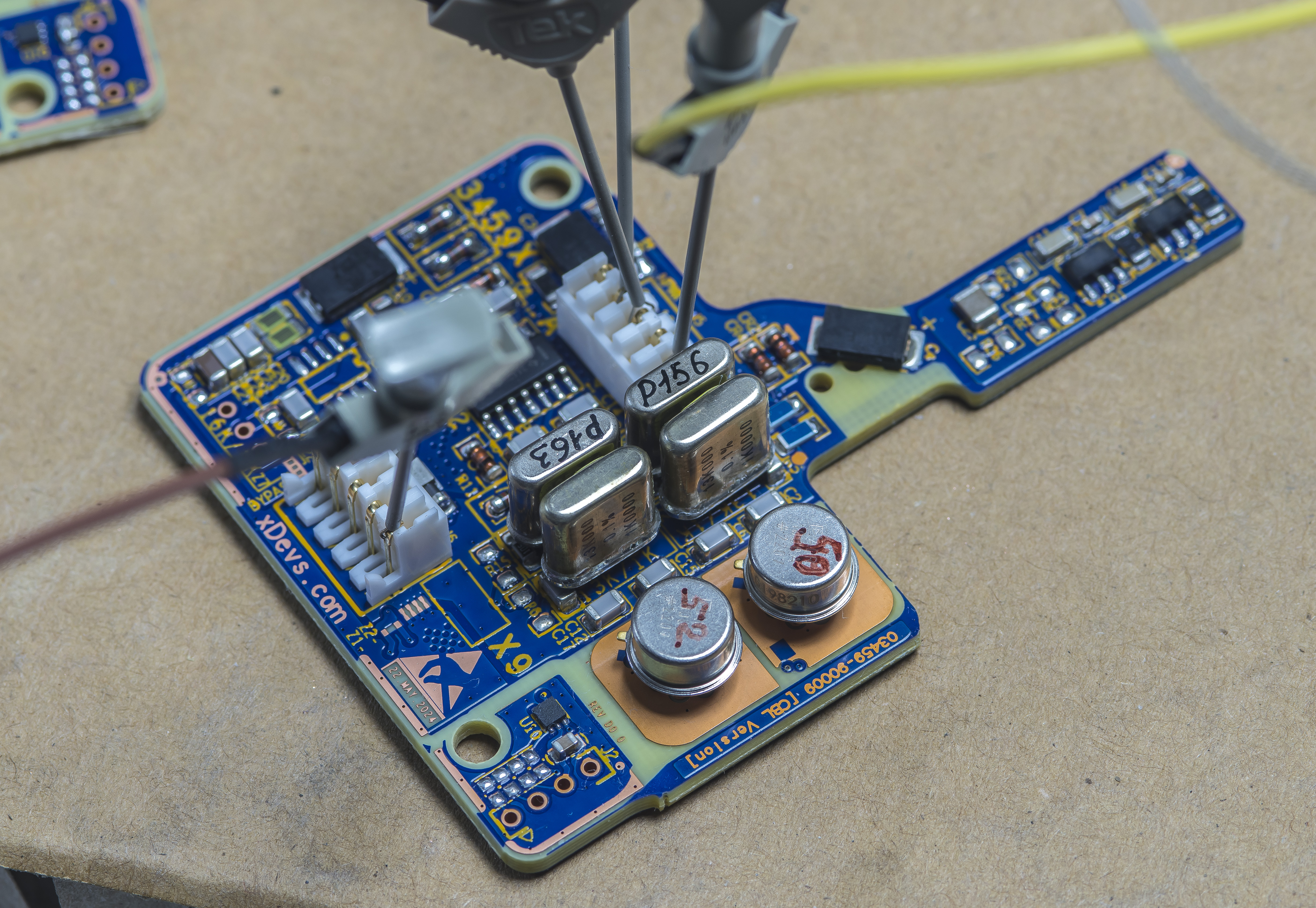
And to push zener noise even further new custom X9-D module implements not just one but two independent ADR1000-based cores on the same 4-layer substrate. Outputs are averaged and combined with passive RC network and optionally amplified to little higher 7.1V level to make this module compatible with standard Rev 9 HP3458A firmware.
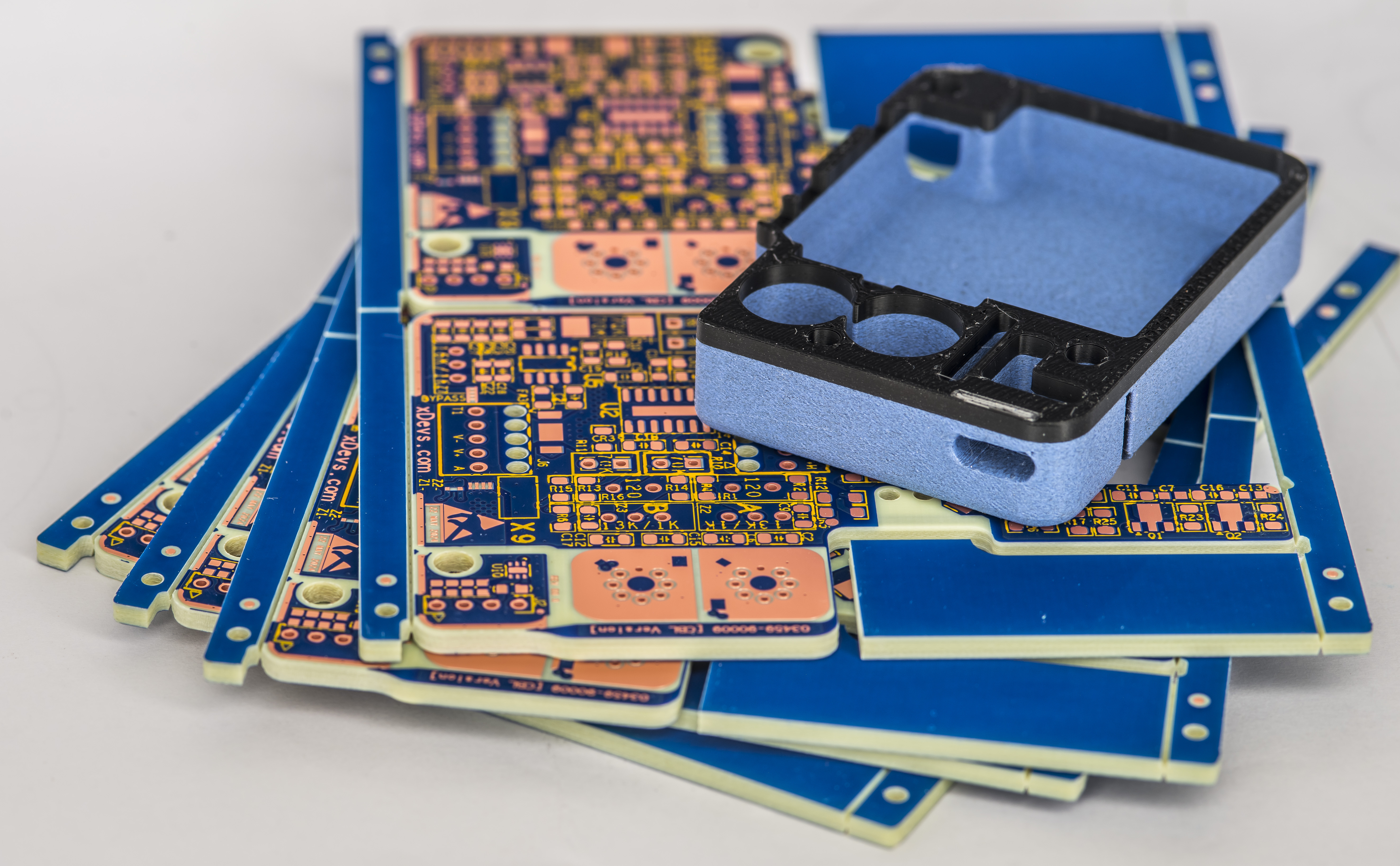
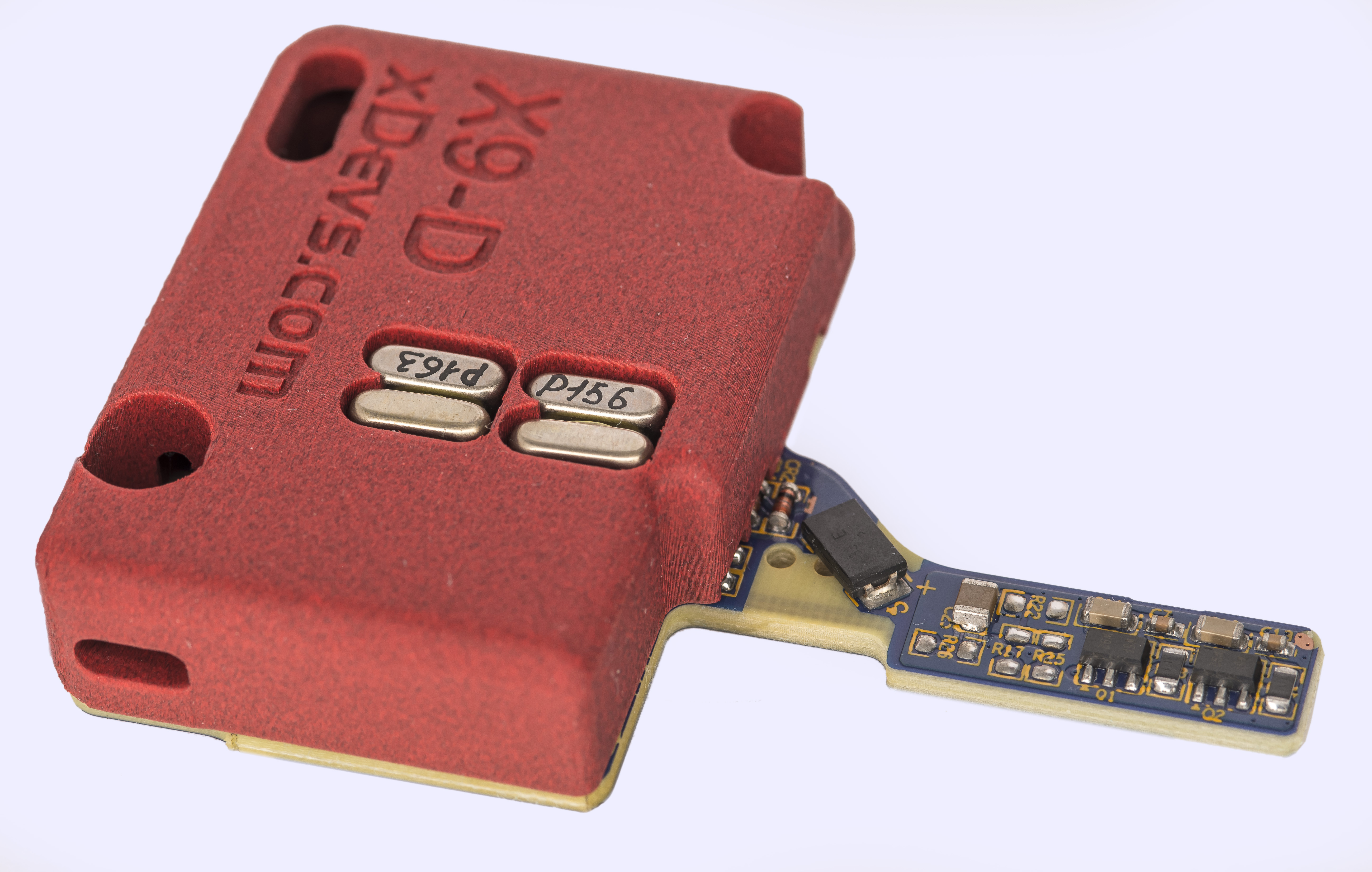
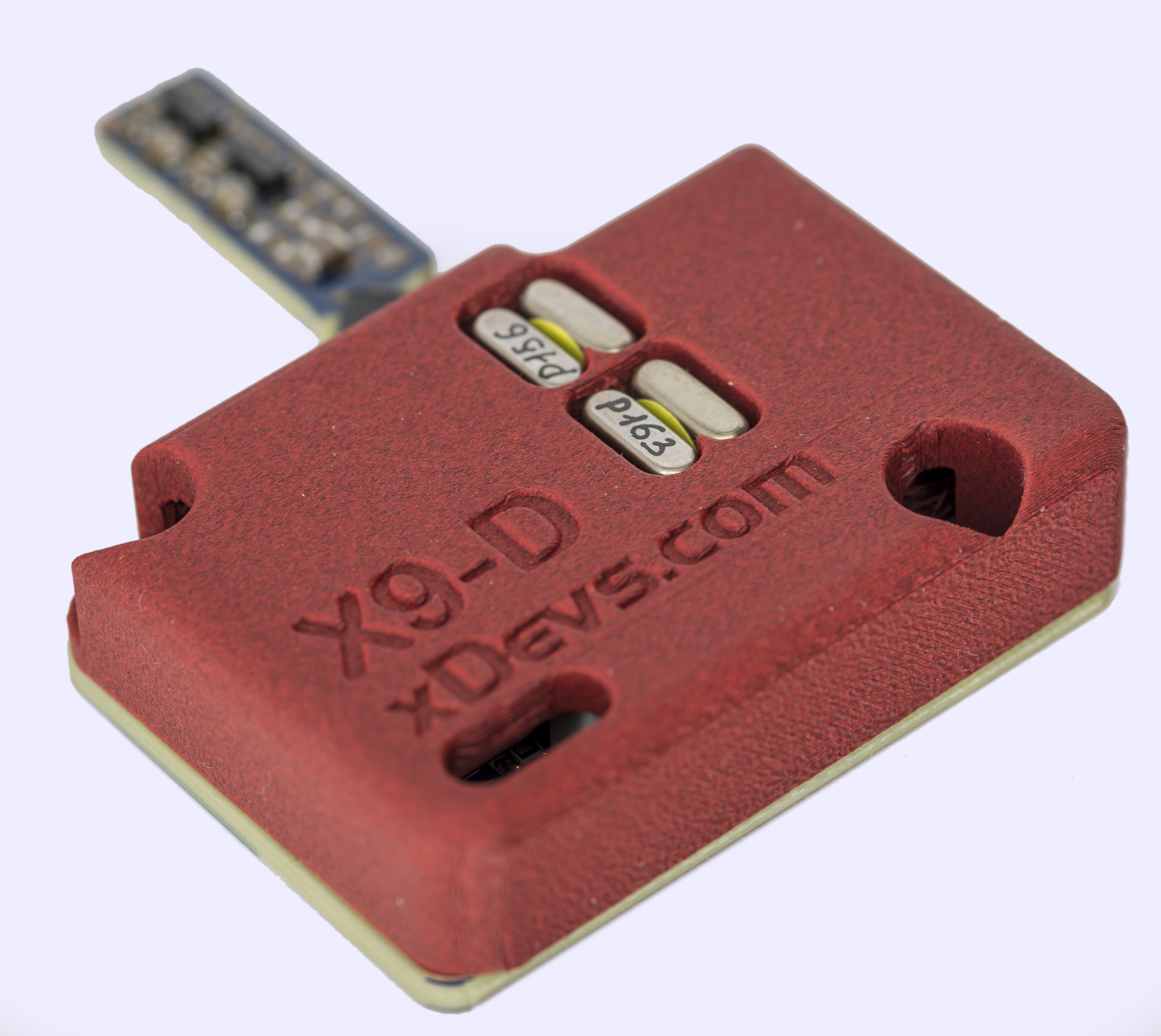
To protect the sensitive reference module from airflow draft and further reduce heat loss module is fully enclosed with 3D-printed plastic cover from both top and bottom sides. Total power consumption of the 6.622V output voltage, with typical dual ADR1000 is about 1 W – 1.3W. PLA-CF material was used with FDM printer to make covers.
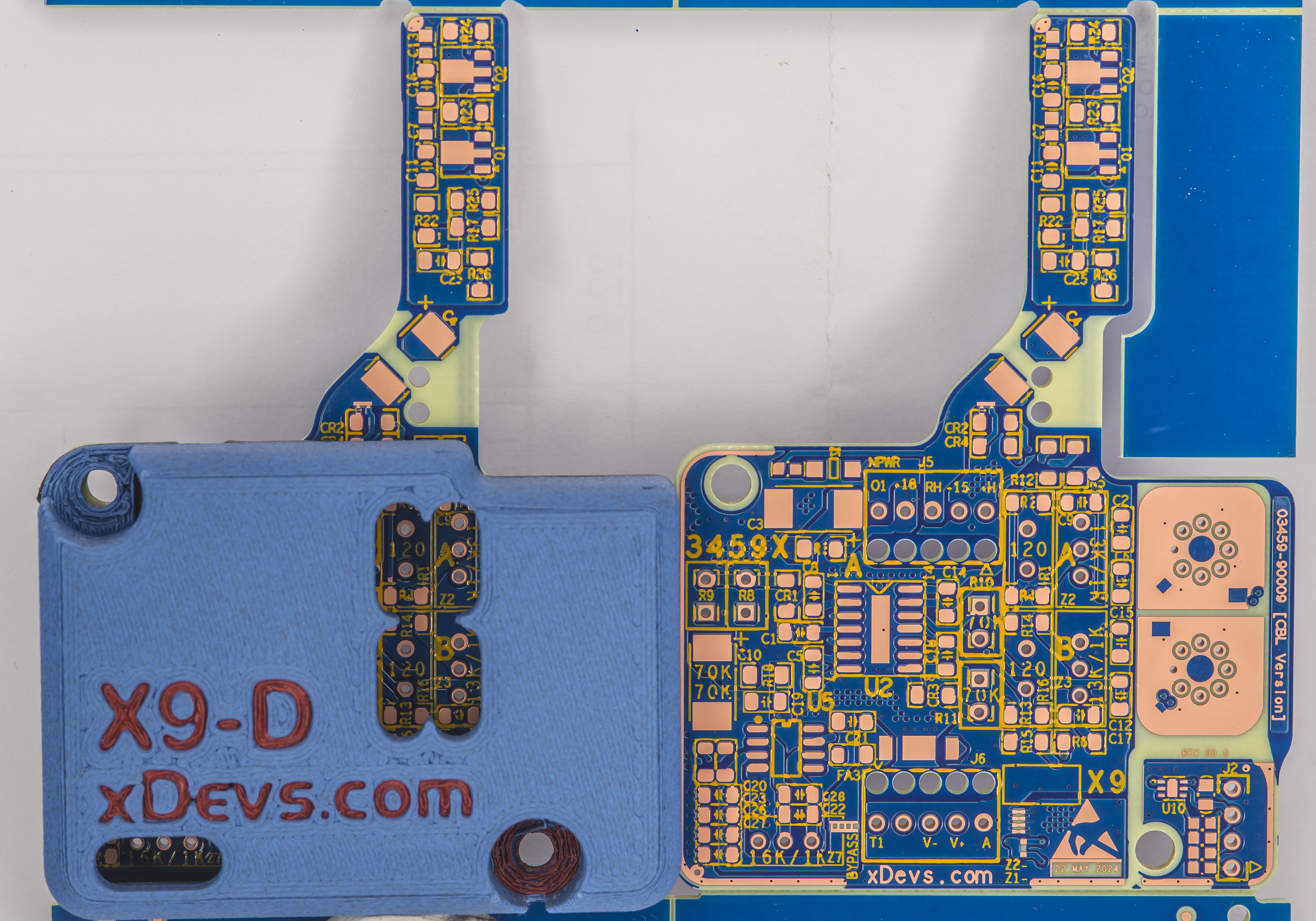
There is also additional fully isolated digital temperature sensor onboard, based on Texas Instruments TMP117 chip in DFN6 package. Hot parts such as power transistors for heater drives and ground current compensation resistors are placed far away from sensitive reference circuits on the non-covered “finger”.
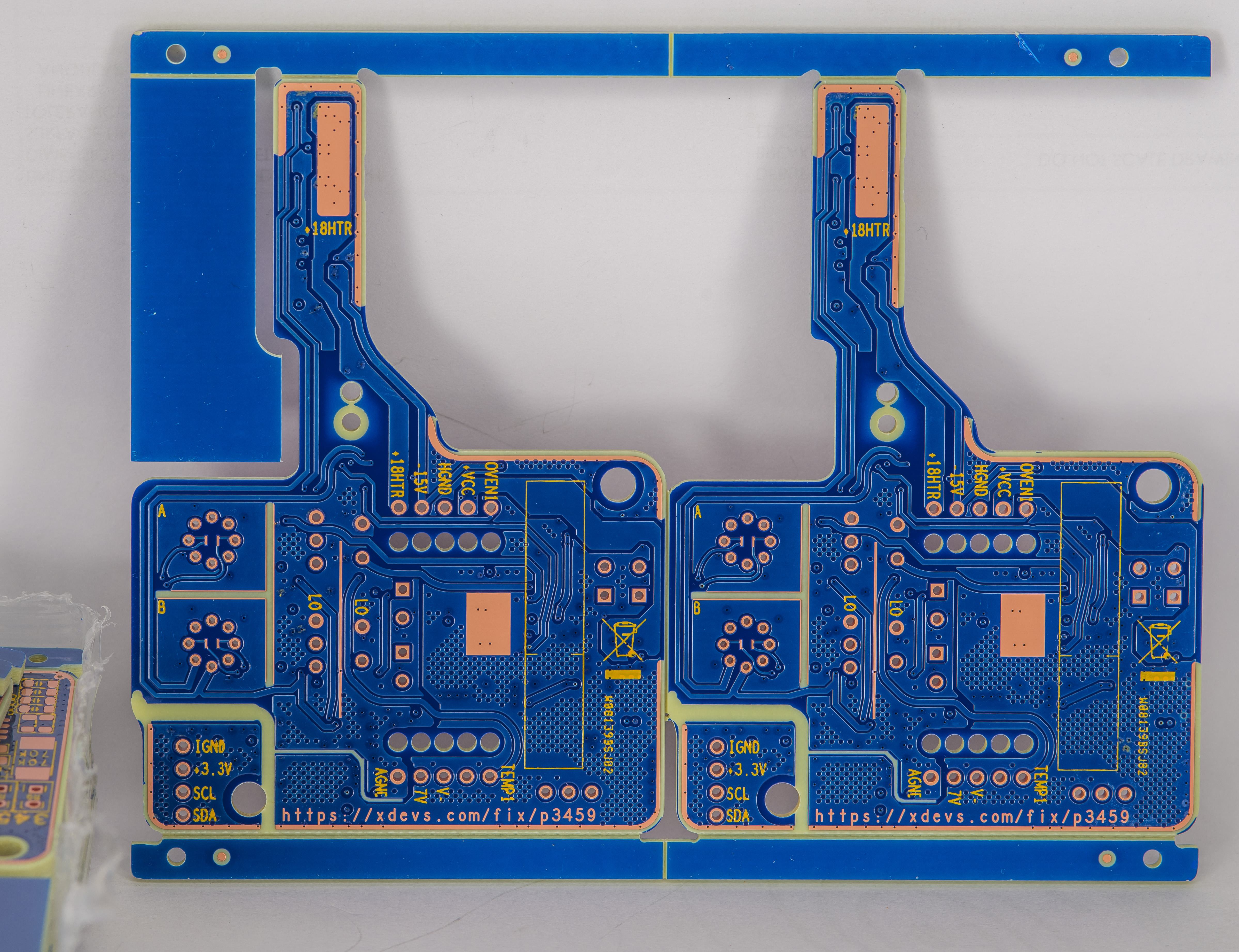
This finger extended across non-critical A1 components closer to the cooling fan, which should help a little with heat dissipation. PCB in X9-D module utilize four copper layers with heavy copper utilization to reduce hotspot gradients across the board. Board is also using thicker dielectric with total stackup height 2.0 mm to further separate sensitive signals from the power and high-current nodes internally. There are no voodoo slots or cutouts, since the module is quite small and does not have rigid mount to the instrument enclosure.
In essence this X9-D design is evolution of our internal quad-zener 6-layer module QVR but at half of the price, half the power and quarter of the physical footprint area.
All the components are mounted only on the top side, this way single side stencil can be used for SMT assembly. Key important resistors are BMF type such as Vishay Precision Group VHP202 and VHD200 to ensure low tempco and good long-term stability of zener temperature setpoint and current. Board plugs into 3458A’s A1 board the same way as original. XDA is a bit wider but there is still room left to clear the area for the cables from instrument’s rear terminal posts.
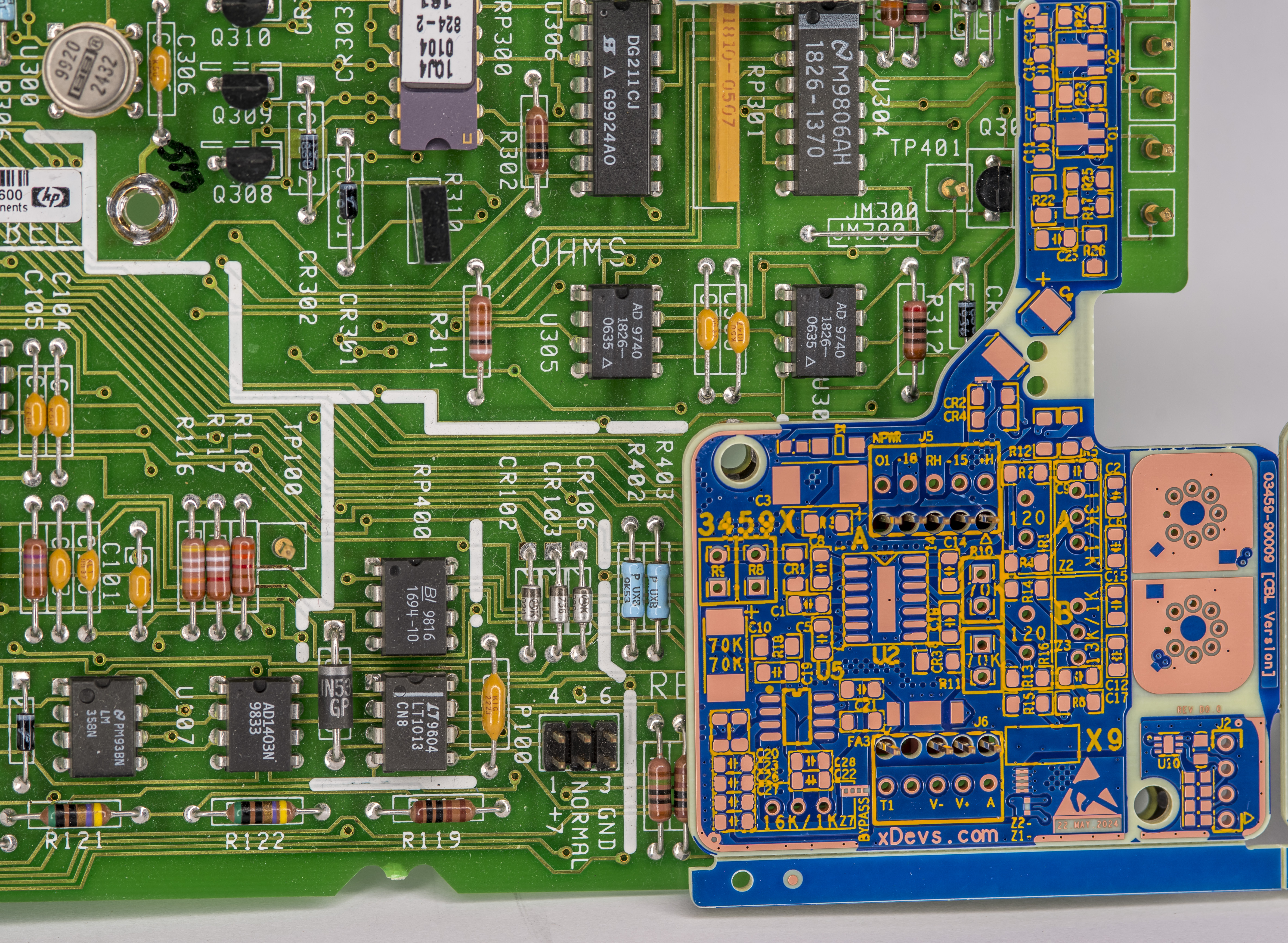
Finger on X9-D module just clears test probe points on A1 and Q30 TO-92 transistor. There are just few digital control components in the area on A1 board, so added heat should not be much of a problem here. But this will be tested later on as well to confirm good resistance function operation.
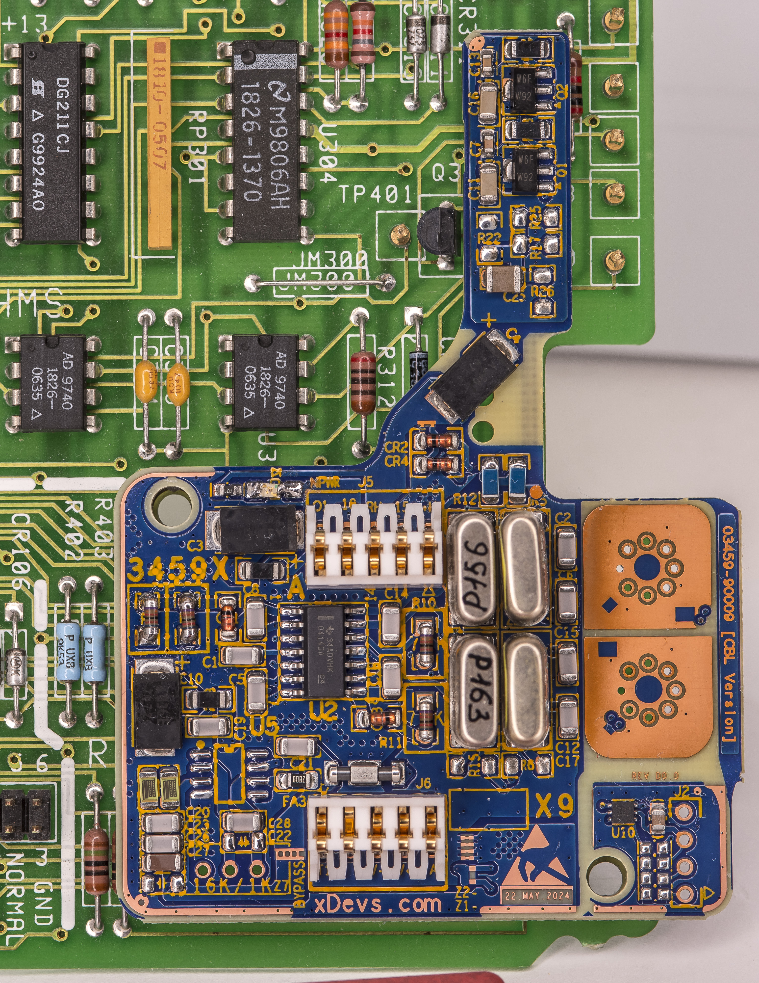
For first prototype I’ve chosen 13 kΩ | 1 kΩ resistor network in as well as 80 Ω current setting resistor. Both are metal foil type in the hermetic packaging to maintain good temperature and long-term stability. At least we wouldn’t have to worry about these resistors in design.
First module was assembled 14 June 2024. It featured two ADR1000 chips and does not have optional boost stage. Initial output voltage was measured at +6.6227 VDC ±2 µV/V. ADR chips were not aged or treated prior to assembly.
Initial 6.622V output noise measurement with standalone X9-D module and paired ADR1000 using 0.1 Hz – 10 Hz 80 dB LNA revealed very promising performance. X9-D was powered from the Fluke 792A power battery pack to ensure quiet power and avoid any chance of the ground loops that might affect sensitive measurement.
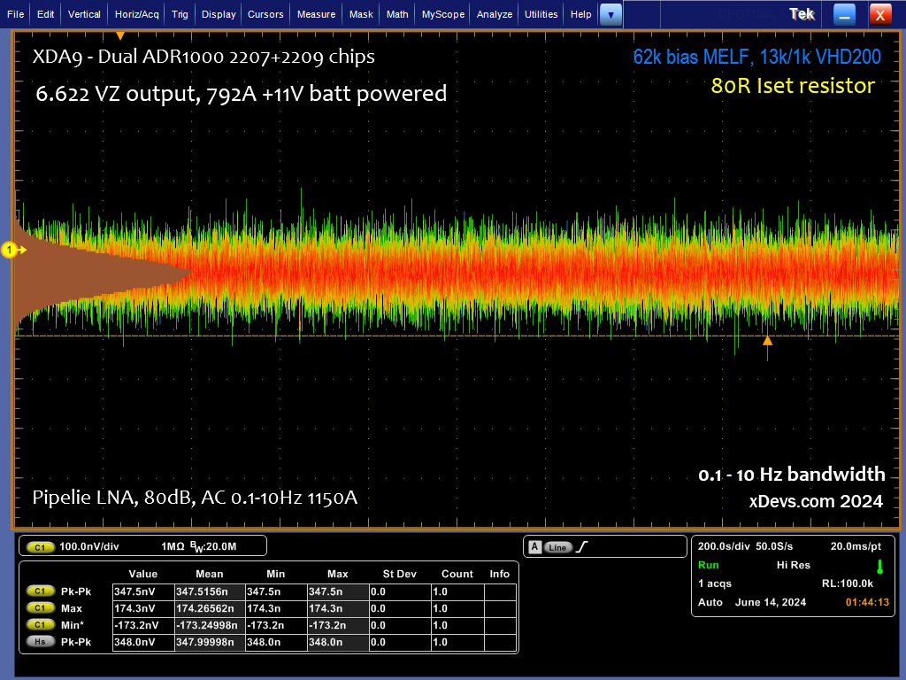
This noise level at ~347 nV peak to peak is well in line with theoretical expectation which was: ~500 nV noise from single ADR1000 / SQRT of two (zeners) = 353 nV peak-peak. Zener current for both chips was set to be around 5.5 mA so there is still some more room to reduce noise by increasing current.
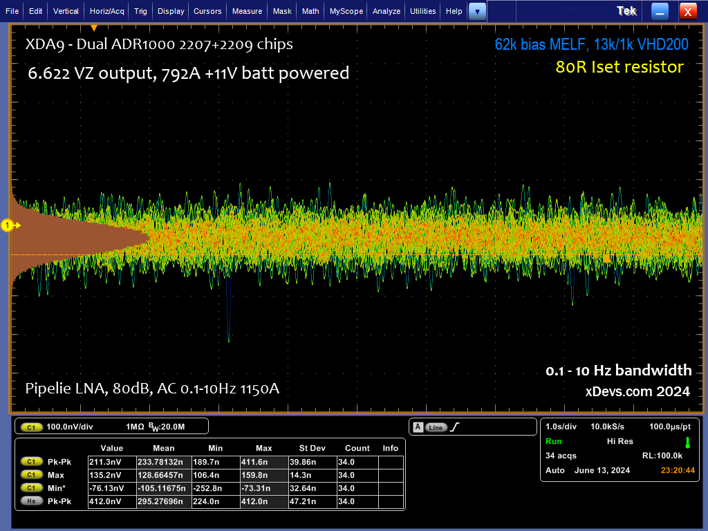
On the shorted time span noise is even lower, around 234 nV peak to peak across 34 captures in 0.1 Hz- 10 Hz bandwidth. This is more than 4 times quieter than factory original 03458-66509 LTZ1000A-based module and should unlock the possibility to test other modifications to this meter with the aim of improving short-term performance for the DC voltage measurement function.
Benchmarks and tests on final modified “P3459” DMM
TBD 2025
Noise and resolution verification
TBD
Voltage coefficient verification
TBD
Temperature coefficient verification
TBD
Stability over longer time periods
“
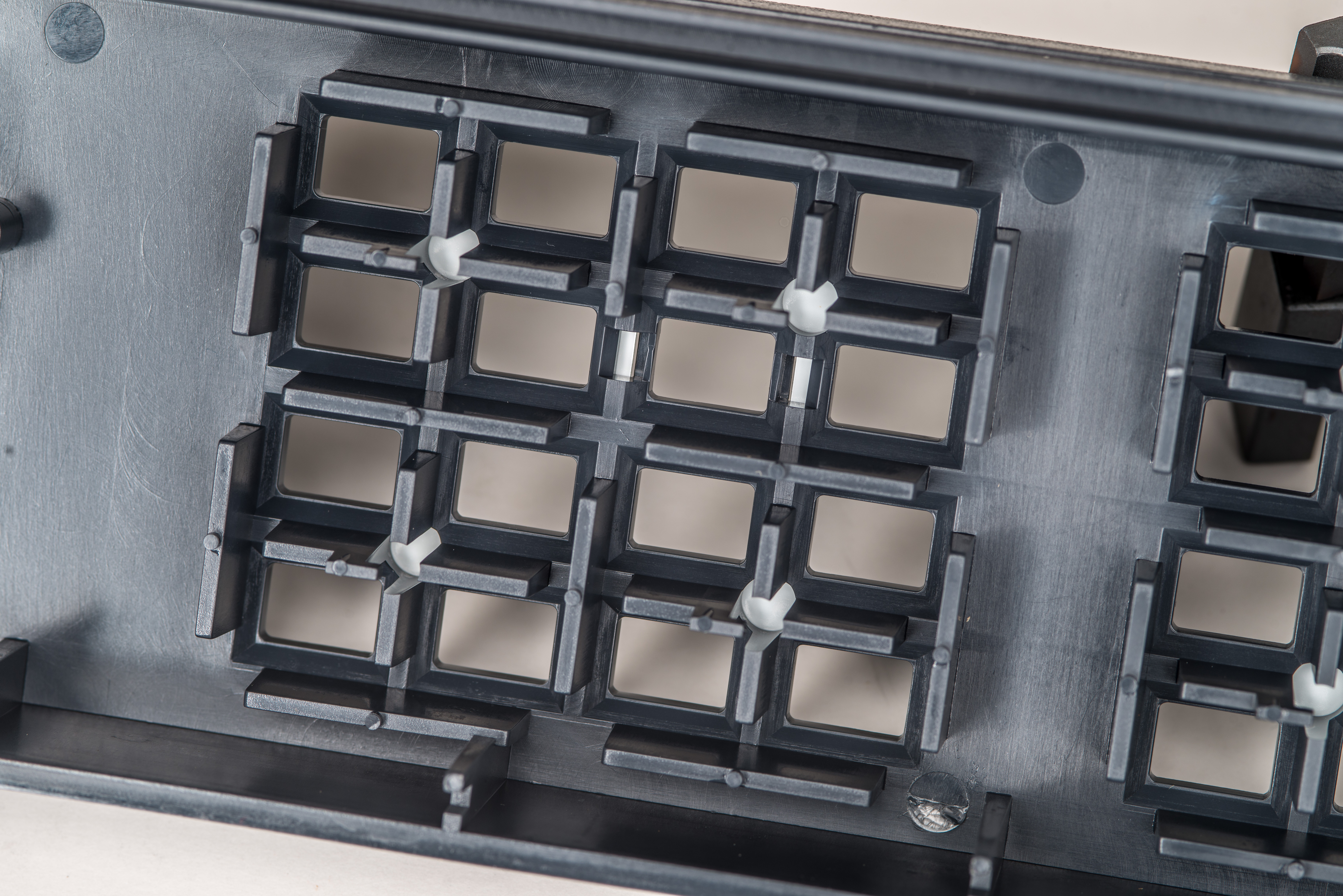
Little fun mod – painting the rest of the covers black too
Welcome to the dark side. Glorious test meter in this article also get a refreshed parts without physical damages.
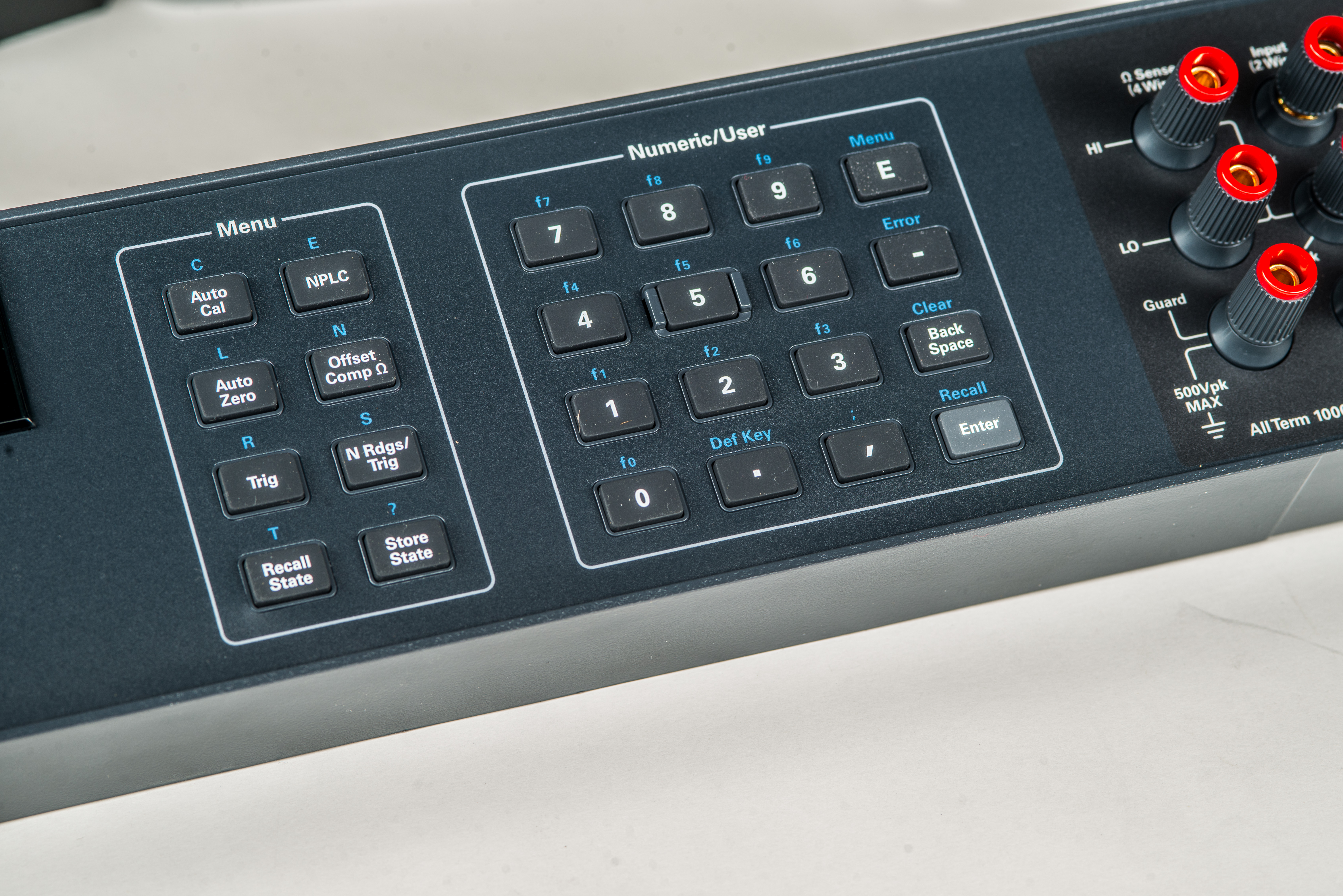
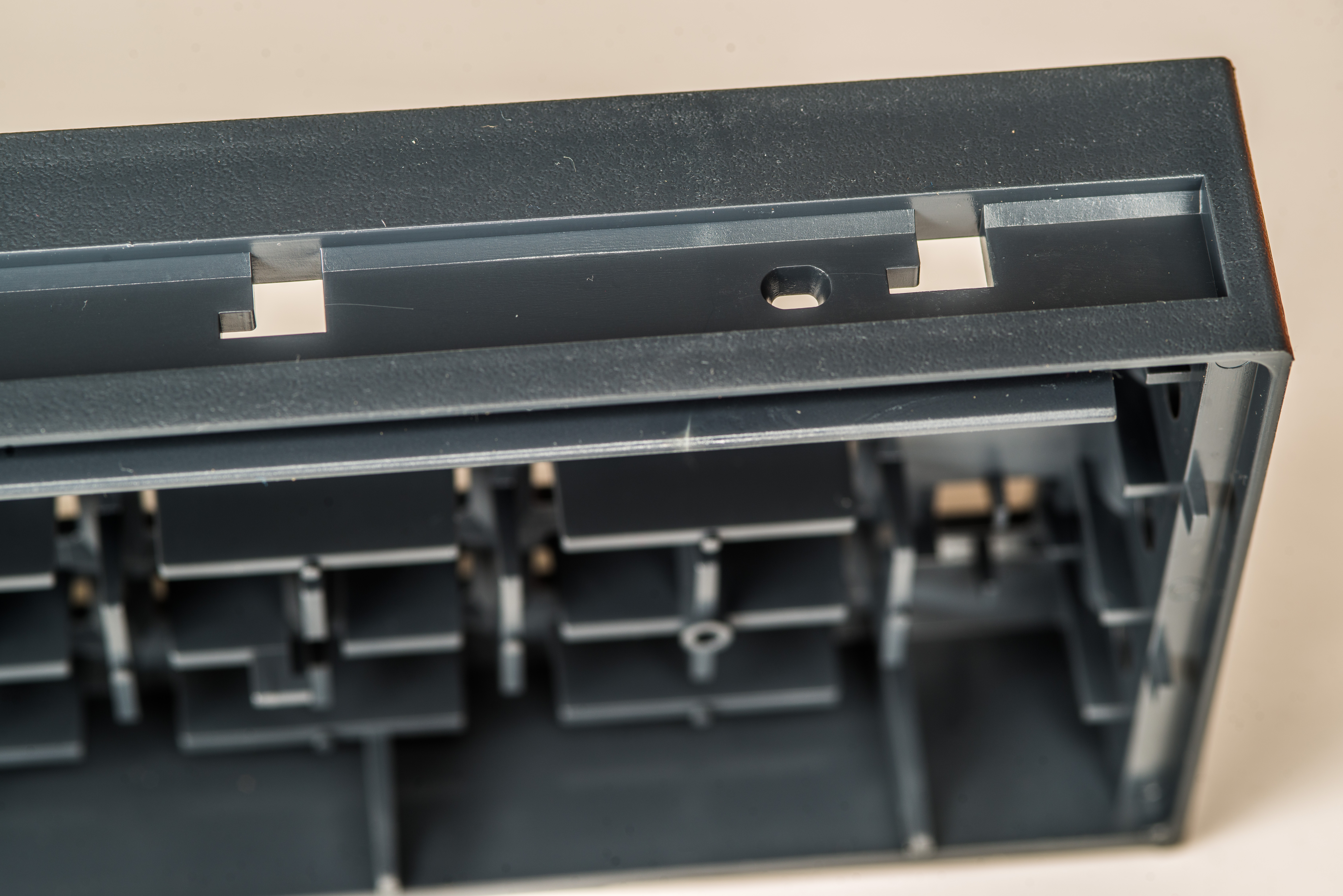
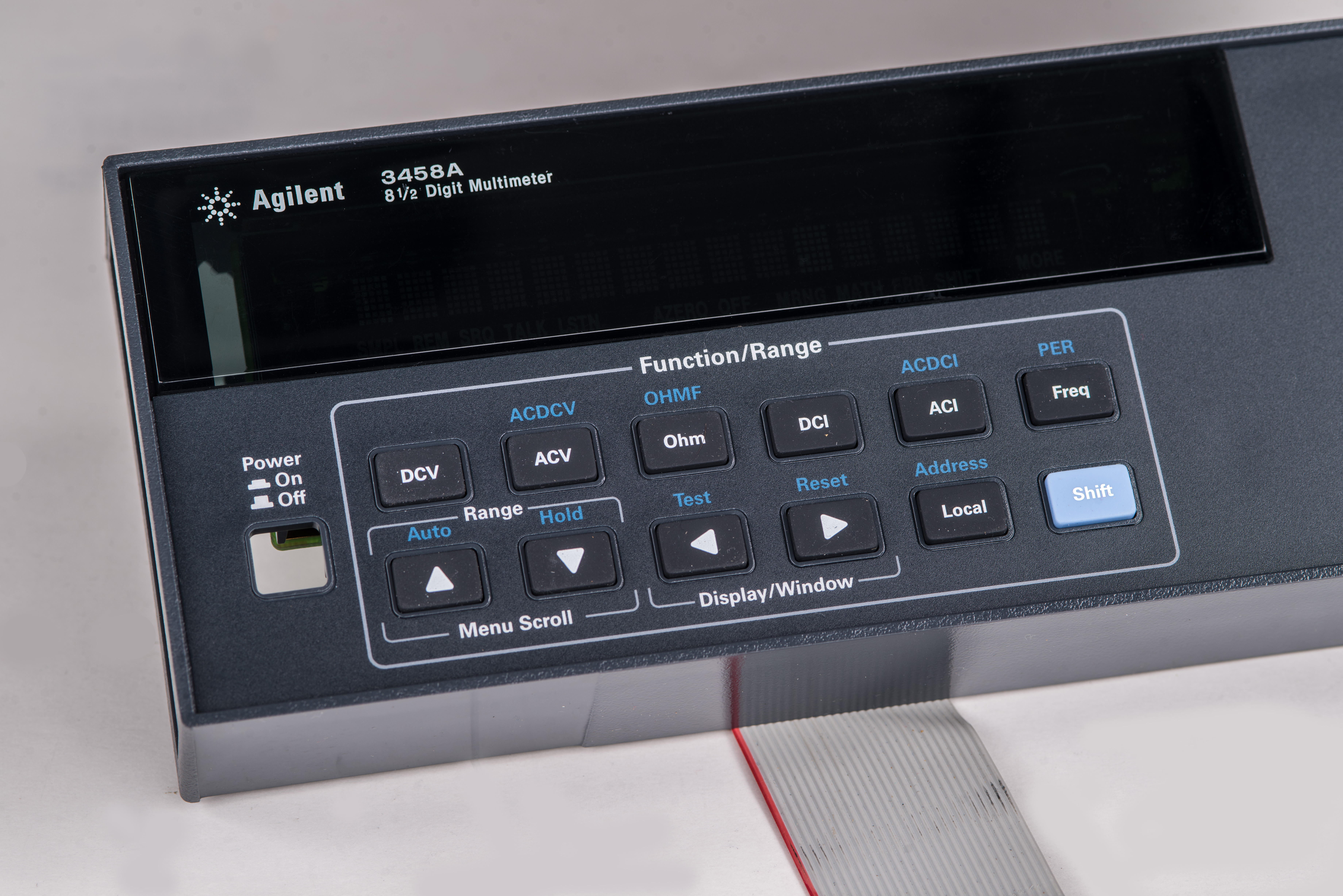
Can’t call the meter black if its just the front panel that is black. Got to have it all same.
Time to get creative and take the case into own hands, with the aid of usual can of black paint from nearest Home Depot home improvement store.
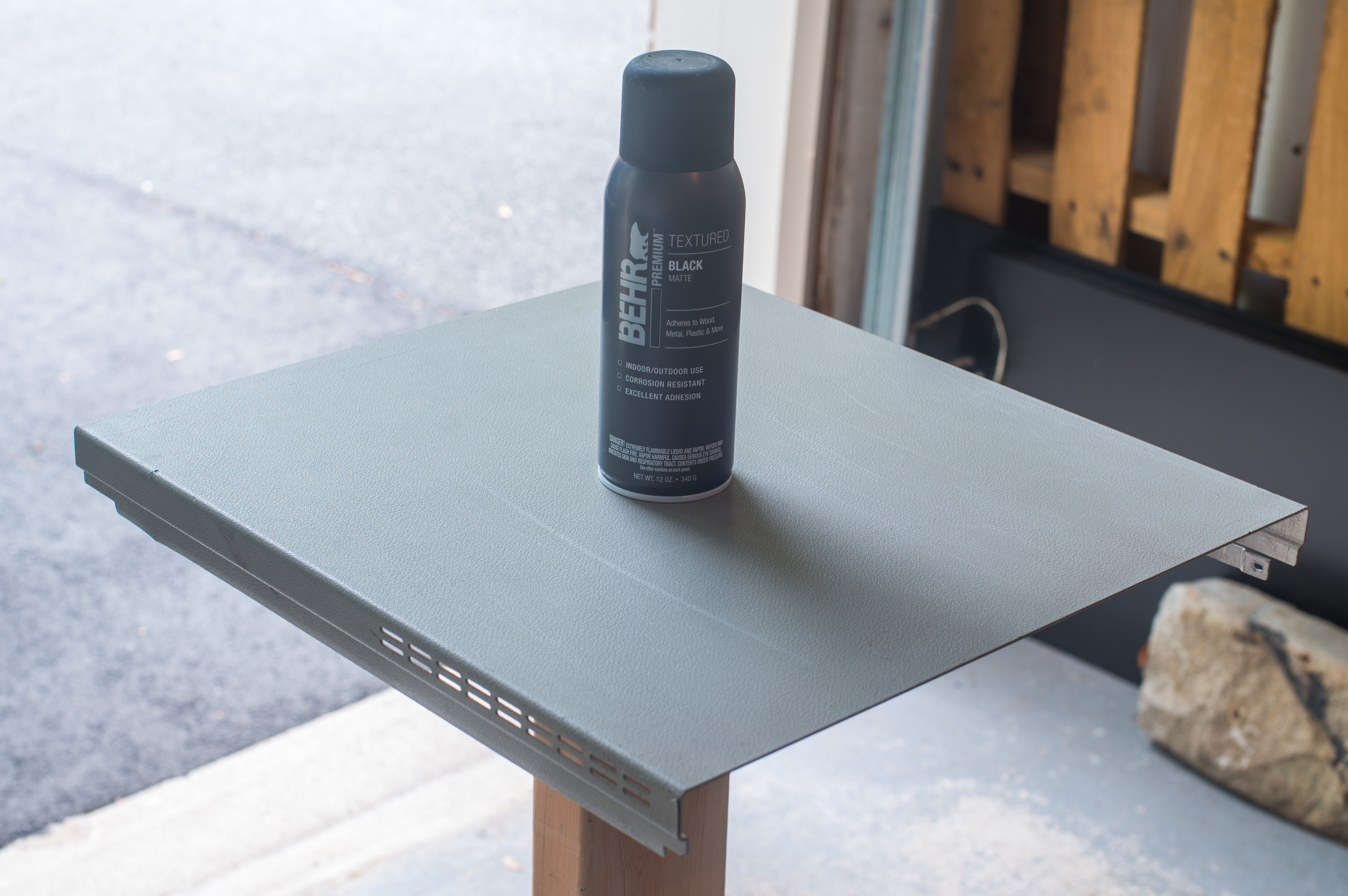
Panels were carefully cleaned with brush and 99% IPA to get rid of contaminants and finger grease and let to dry a bit in garage. Next few layers of paint were applied on the surface and let to dry for a bit.
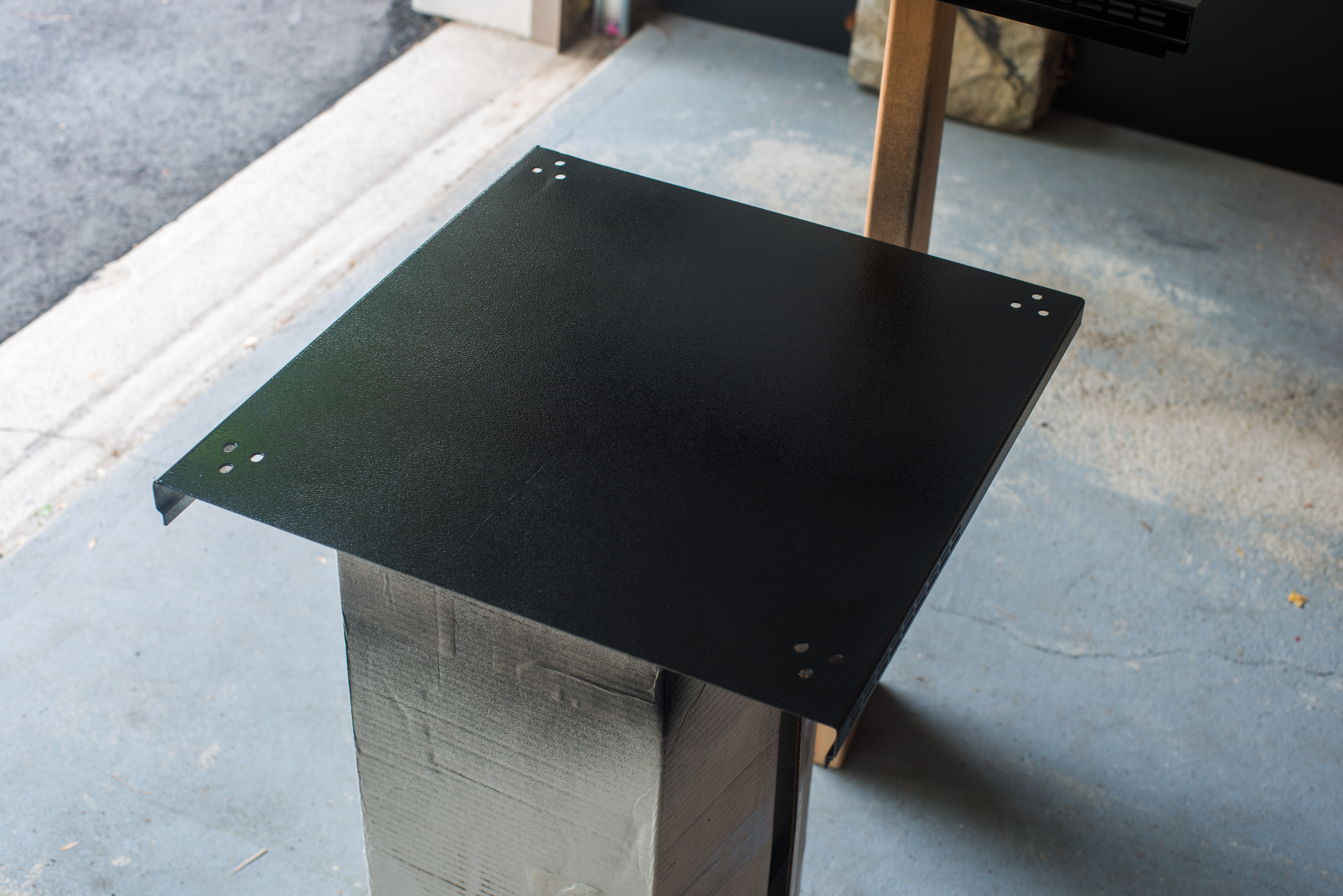
Next day covers were taken to match with meter for test fit.
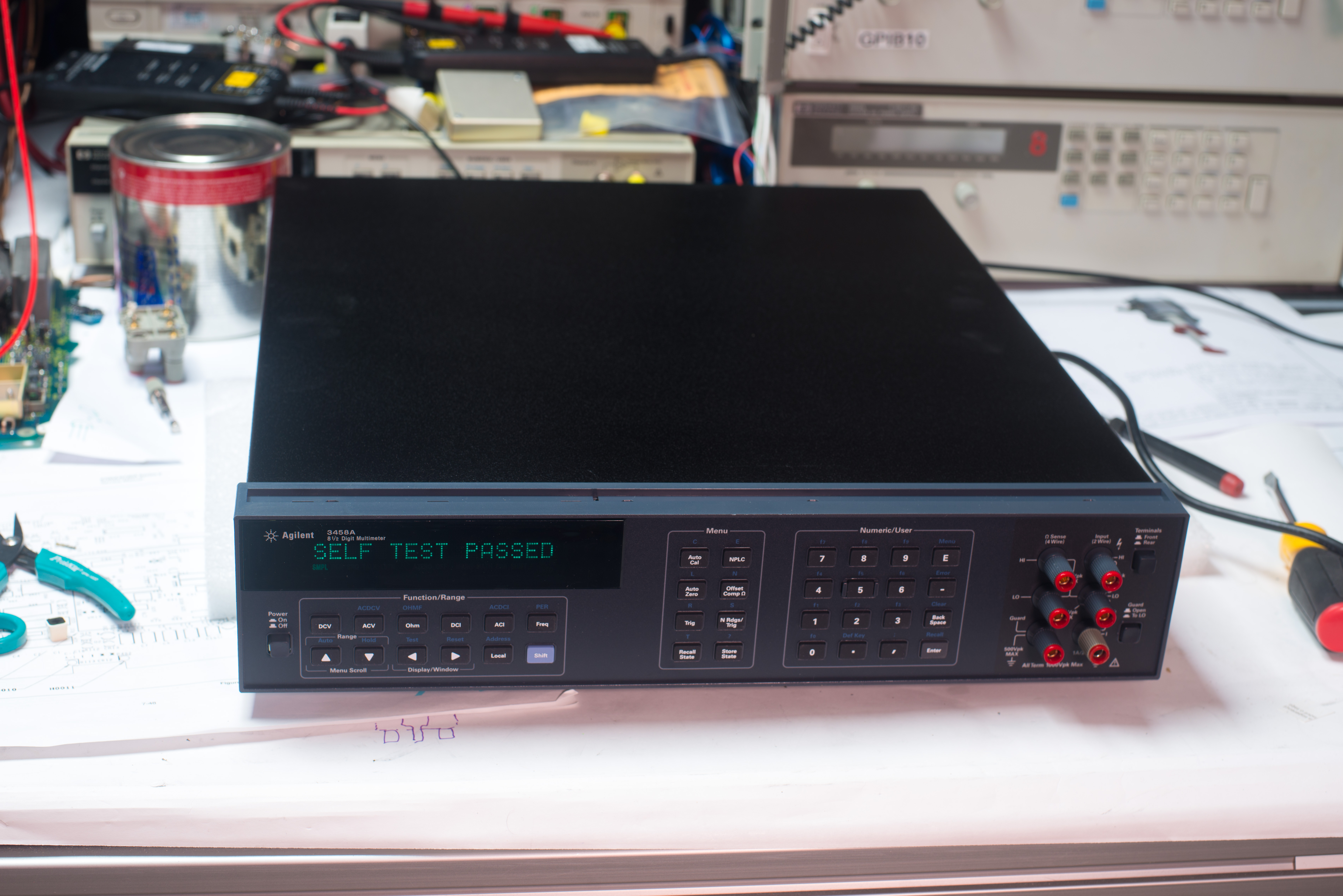
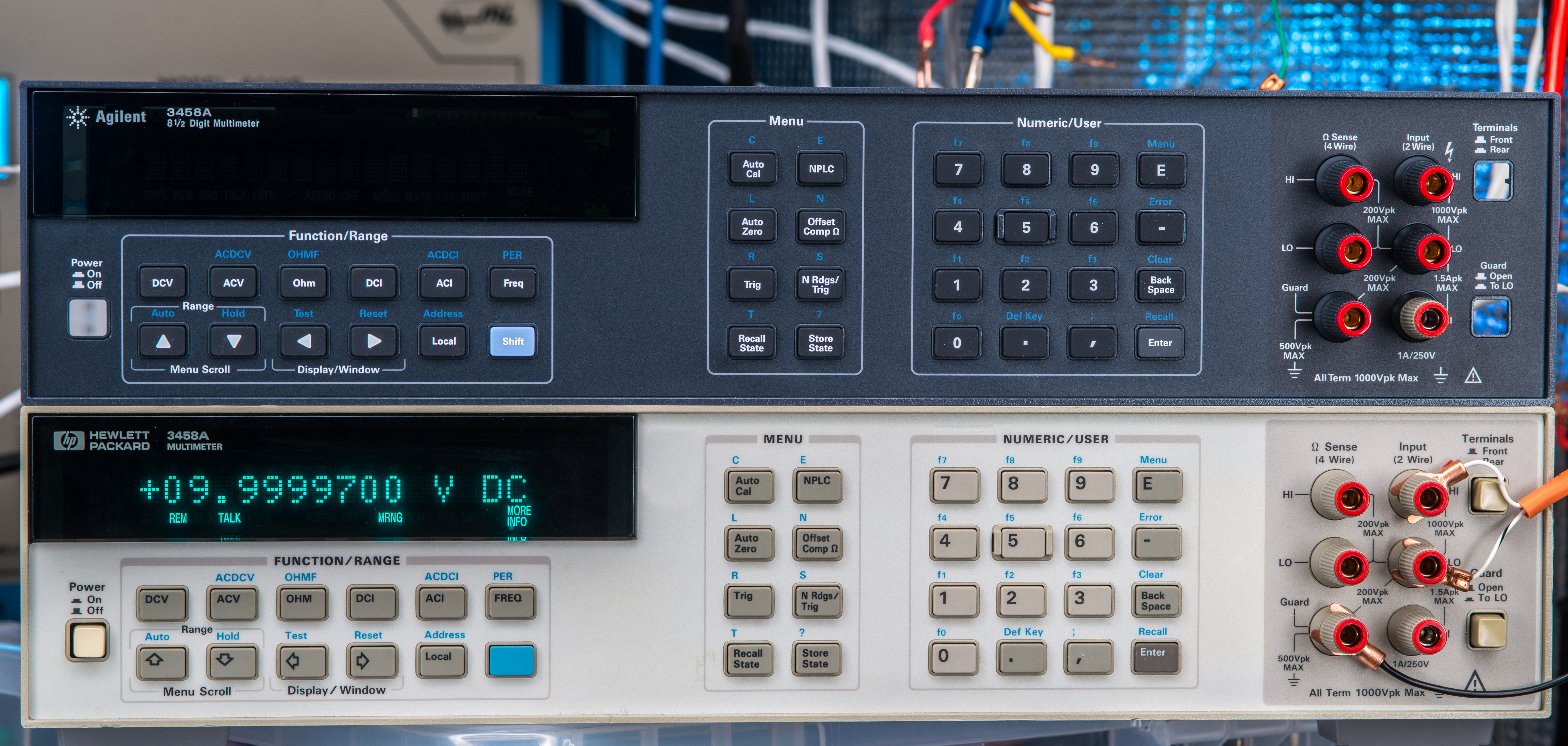
Pretty cool to see much darker black shine compared to original Keysight silvery-flaked exterior covers color.
For a little comparison here’s how actual current Keysight 3458A RoHS meter looks in same perspective:
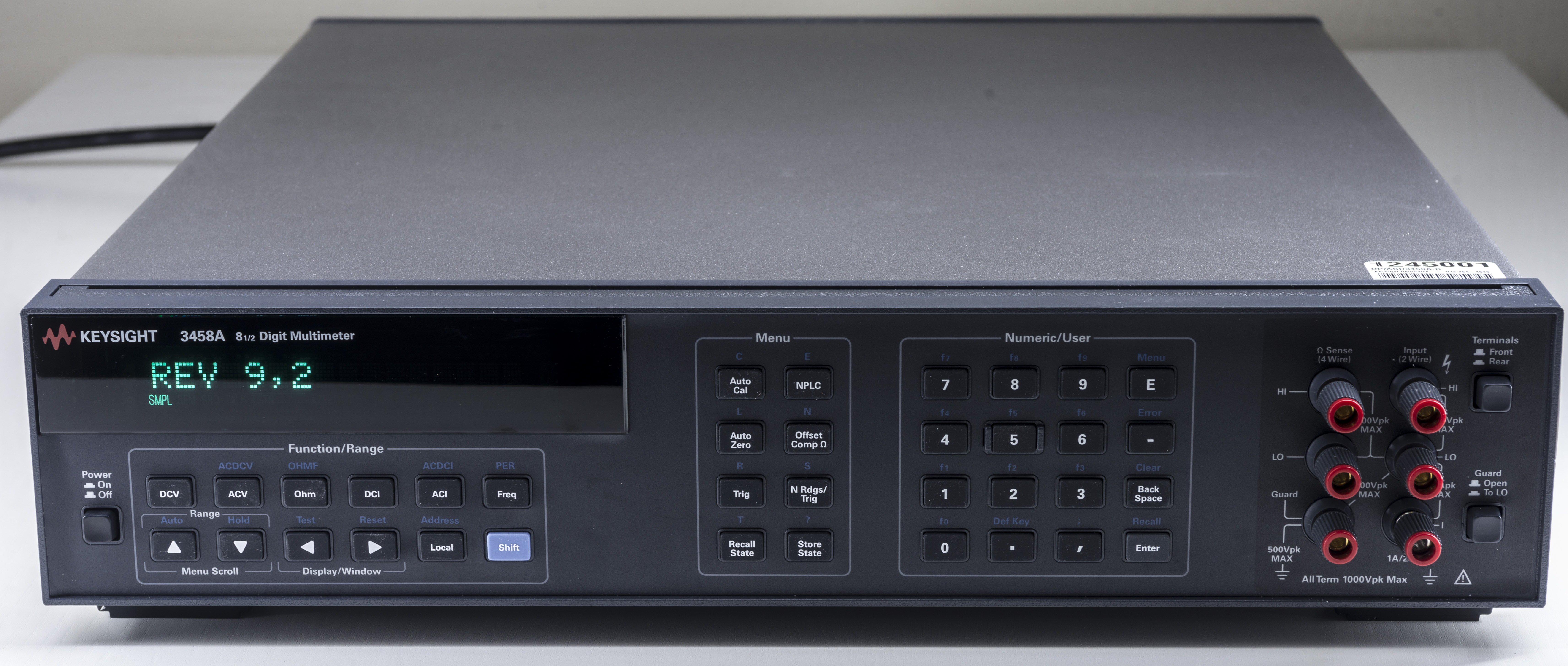
Image : Keysight 3458A RoHS refreshed 8½-digit multimeter
Please note, that instrument is built only for the internal testing with various modifications and circuit ideas and will NOT leave our lab or be shipped to commercial laboratory for any formal calibration. This is important to explain this fact before any possible incorrect conclusions on goals of this build.
Conclusion and summary
Time log of efforts dedicated to this project. This is a general timeframe to summarize the efforts.
| Activity | Time log | Dates |
|---|---|---|
| Source parts | 20 hours | 2020-2022 |
| A6 outguard PSU repairs and tests | 1 hours | 31.DEC.2022 |
| A4 inguard PSU tests | 1 hours | 31.DEC.2022 |
| A3 reassembly for test, front terminals reinstall | 5 hours | 30.JAN.2023 |
| Good A3 performance validation | 100 days | Q1 2024 |
| Dual X9 reference module assembly | 8 hours | 16.JUN.2024 |
Table X: Time summary on P3459 project
| Components | Post | Shipping |
|---|---|---|
| 03458-61603 – 2 pcs | $20 USD | $6 USD |
| Transformer | $150 USD | Included |
| Chassis | $220 USD | Included |
| X9-D reference module design and prototypes | $900 USD | Various |
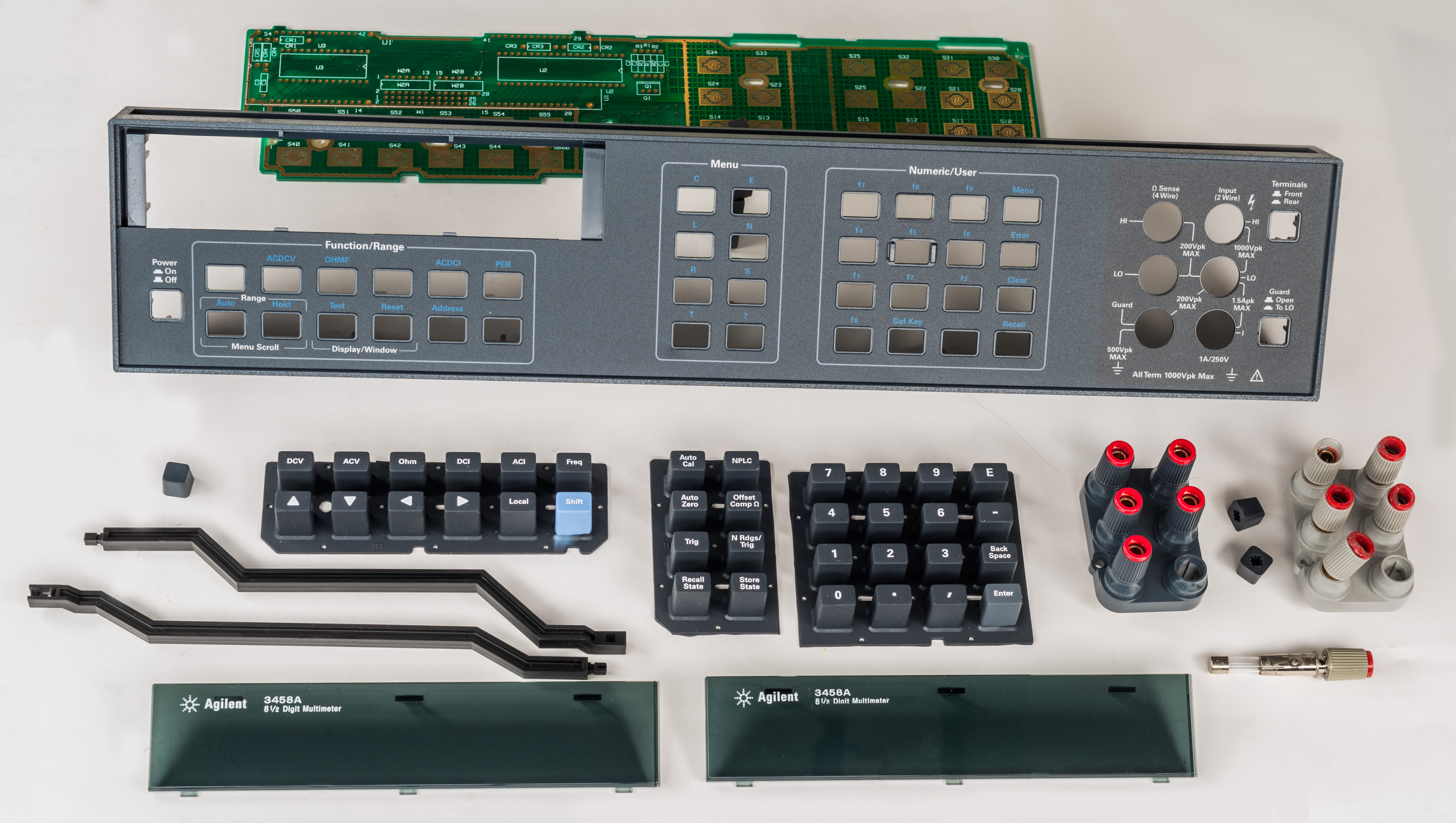
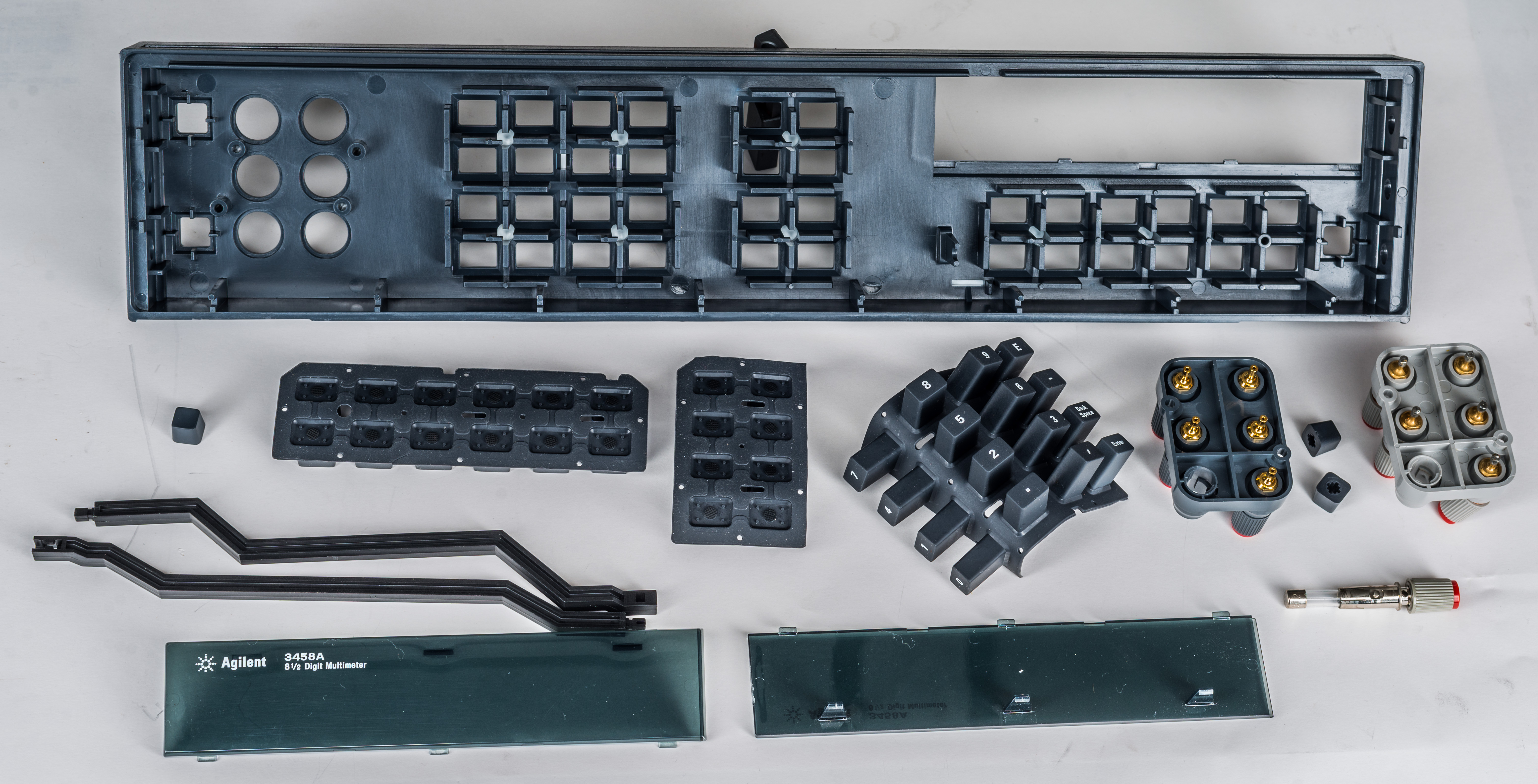
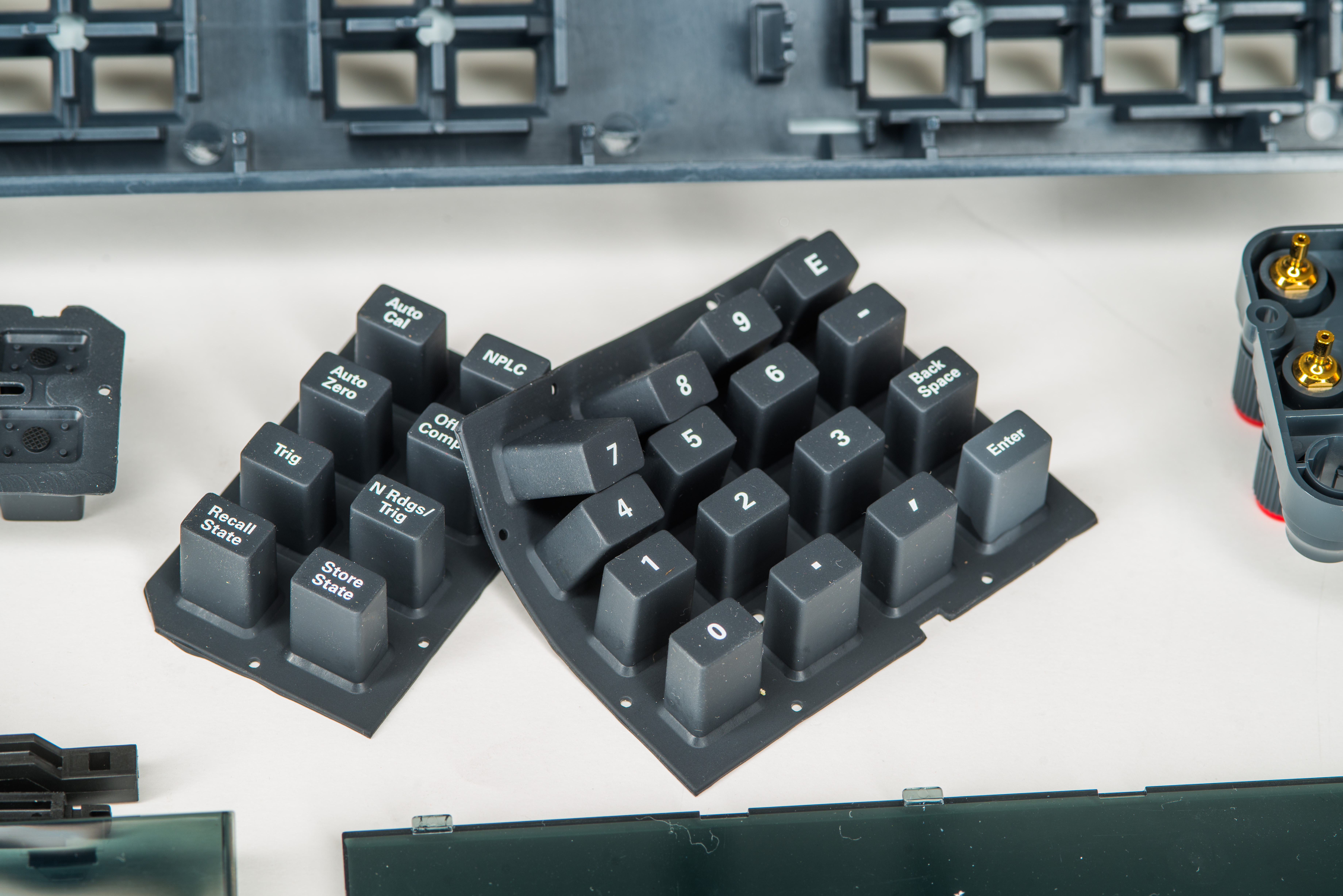
| 03458-40224 × 2 – keycap, carbon black | 17.74 | |
| 03458-40225 × 1 – keycap, phantom gray | 4.11 | |
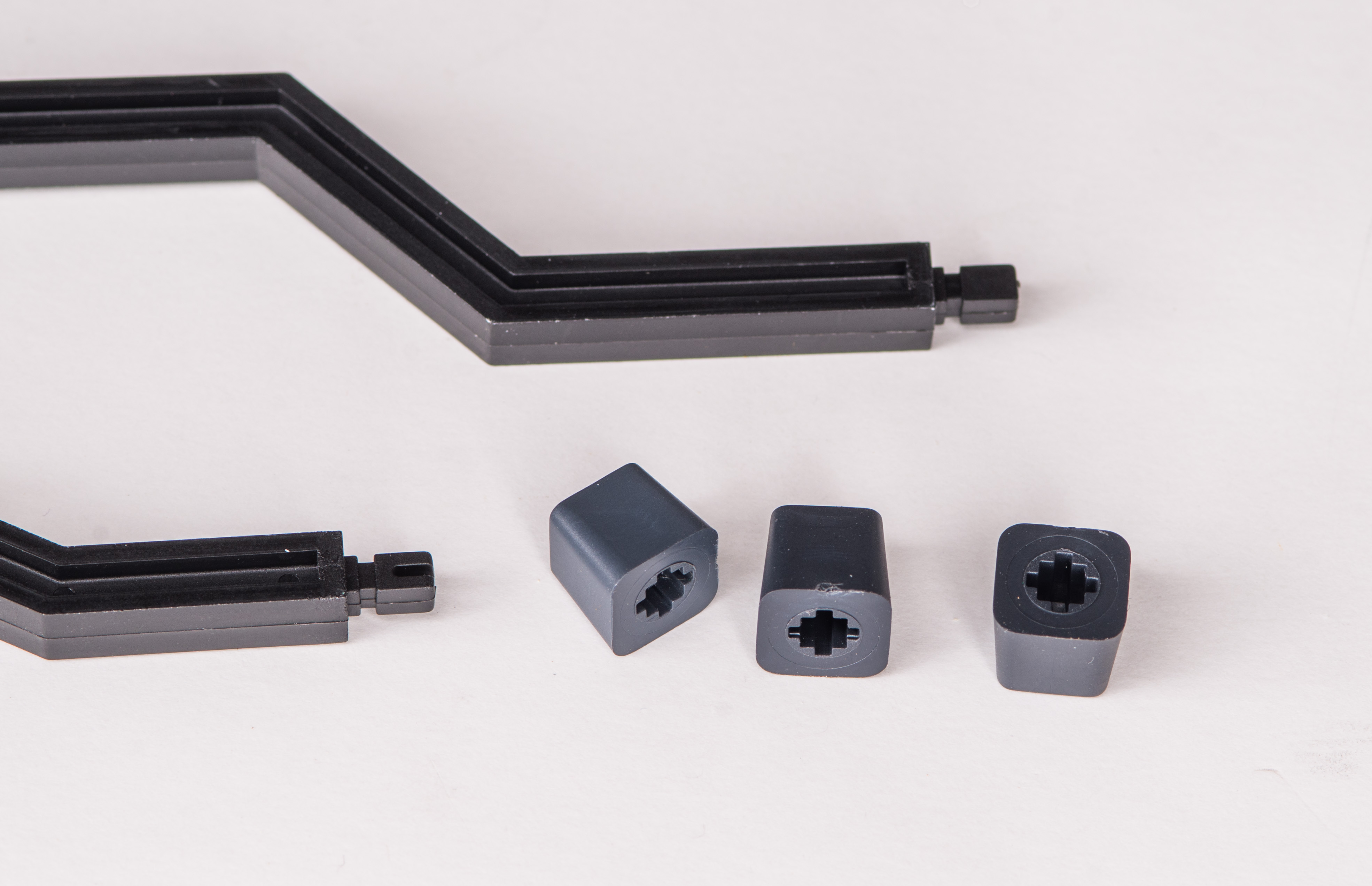
| 03458-43702 × 1 – pushrod guard | 13.69 | |
| 03458-43701 × 1 – pushrod front/rear | 10.82 | |
| 03458-40222 × 1 – front panel | 210.00 | |
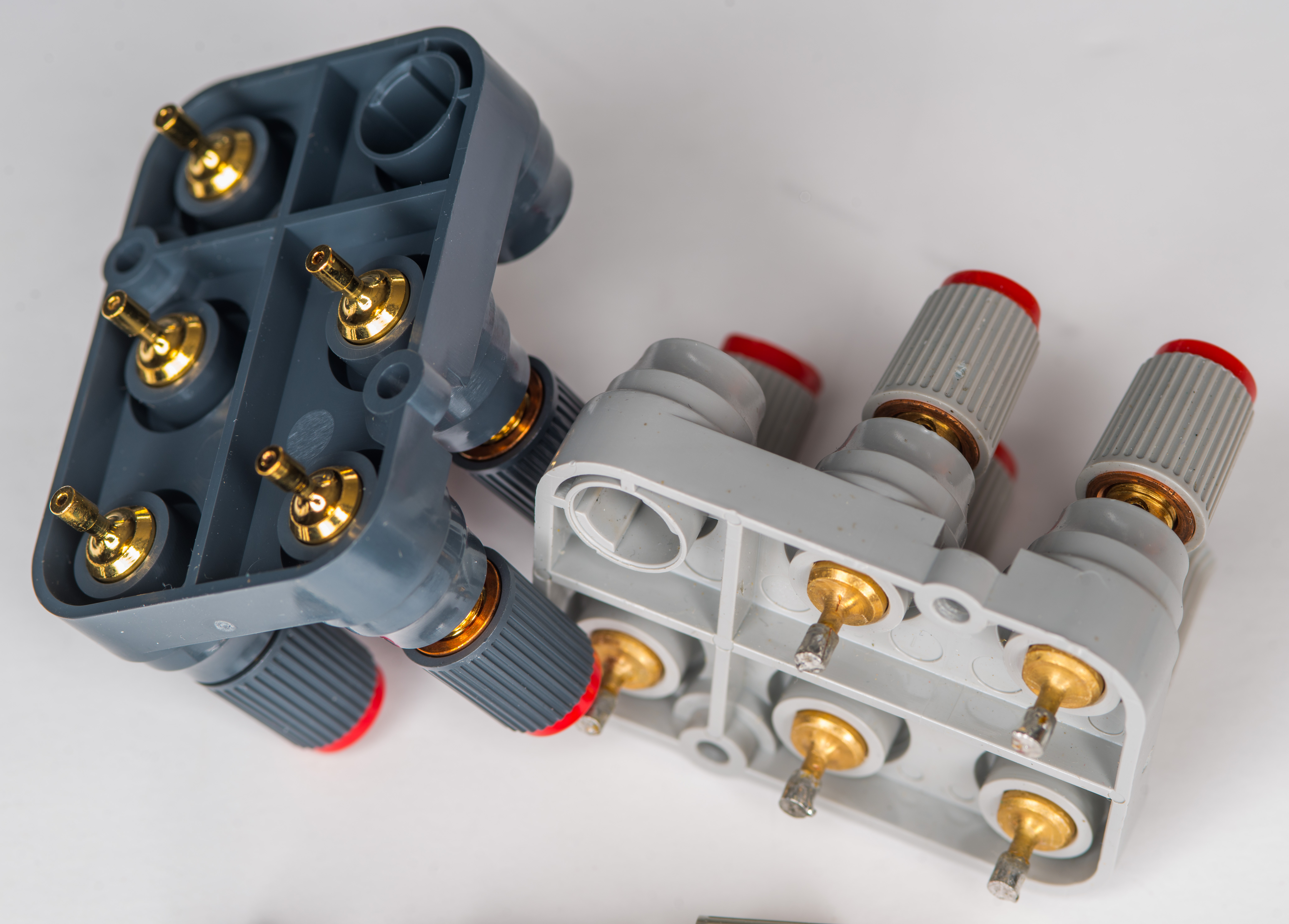
| 03458-62121 × 1 – terminal block | 189.00 | |
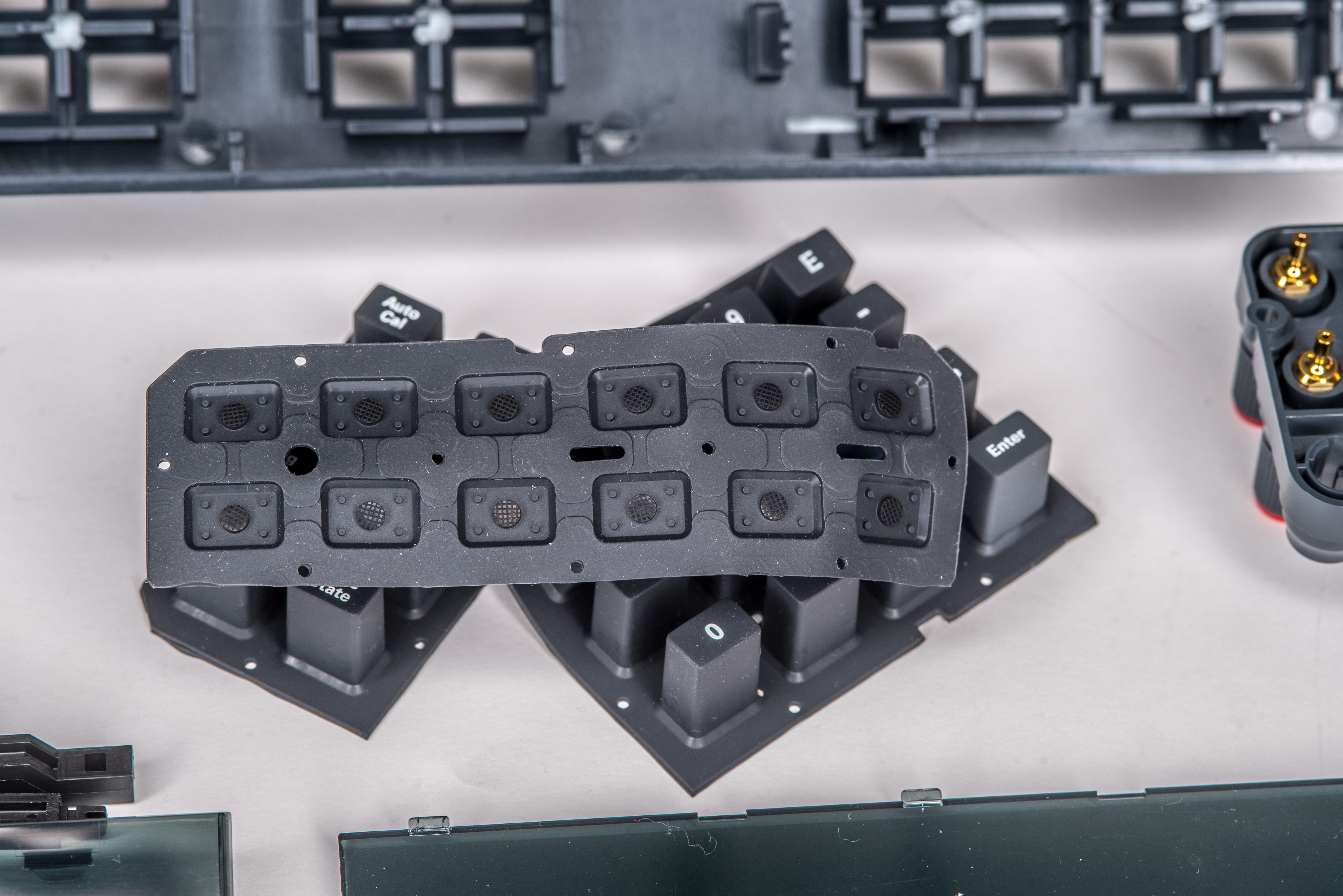
| 03458-81922 × 1 – keypad | 22.83 | |
| 03458-67922 × 1 – black terminal fuse | 20.96 | |
| 5042-8425 × 2 – side trim strip | 13.94 | |
| 5042-8439 × 1 – trim strip top | 8.87 |
Table X: Cost summary on P3459 project
The author would like to express our appreciation to everyone contributed to this project, especially Tom, Martin, Todd and David. Discussion is very welcome thru comment section or at our own IRC chat server: irc.xdevs.com (standard port 6010, channel: #xDevs.com). If you have information and interesting ideas on 3458A hardware modifications not mentioned or listed in this article, feel free to provide them and xDevs will test and add them with next article update.
Projects like this are born from passion and a desire to share how things work. Education is the foundation of a healthy society - especially important in today's volatile world. xDevs began as a personal project notepad in Kherson, Ukraine back in 2008 and has grown with support of passionate readers just like you. There are no (and never will be) any ads, sponsors or shareholders behind xDevs.com, just a commitment to inspire and help learning. If you are in a position to help others like us, please consider supporting xDevs.com’s home-country Ukraine in its defense of freedom to speak, freedom to live in peace and freedom to choose their way. You can use official site to support Ukraine – United24 or Help99. Every cent counts.
Modified: March 25, 2025, 9:19 p.m.